EBG Resistors Product Catalog - Dralmi
80
EBG Resistors Product Catalog Issue 2018
Transcript of EBG Resistors Product Catalog - Dralmi
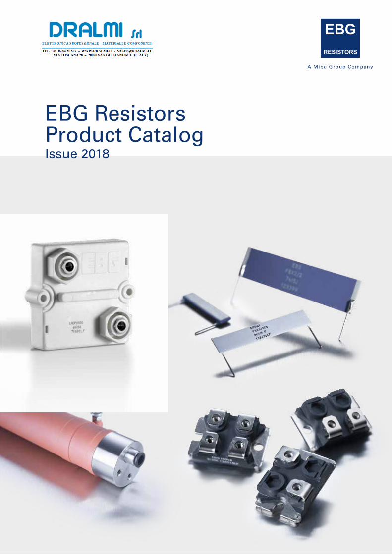
EBG Resistors Product CatalogIssue 2018

EBG Elektronische Bauelemente GmbHKirchbach 3848082 Kirchbach-ZerlachAUSTRIAT + 43 3116 2625 0F + 43 3116 [email protected]
North American Sales - Distribution EBG Resistors, LLC460 Spruce StreetMiddletown, PA 17057USAT +1 717 737 9877F +1 717 737 [email protected]
Contact details:
www.ebg-resistors.com
[email protected] · [email protected]
Introduction
Content
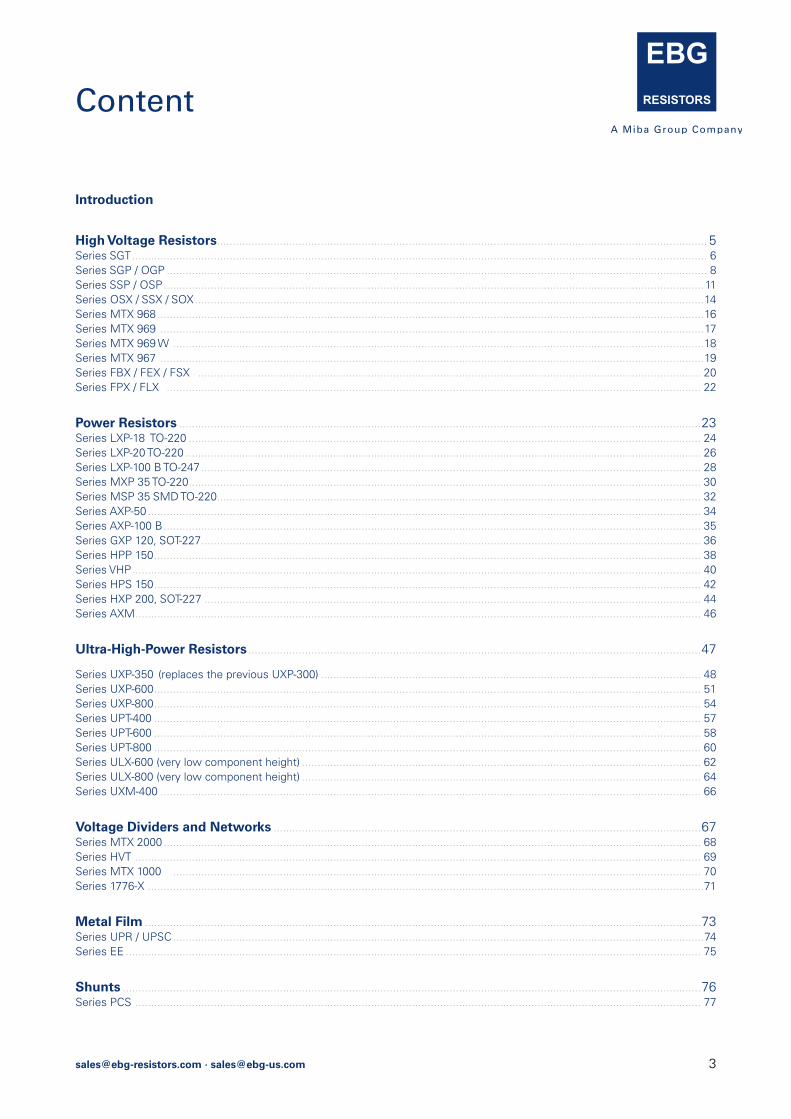
High Voltage Resistors ............................................................................................................................................................ 5Series SGT ....................................................................................................................................................................................... 6Series SGP / OGP ............................................................................................................................................................................ 8Series SSP / OSP ............................................................................................................................................................................11Series OSX / SSX / SOX ..................................................................................................................................................................14Series MTX 968 ..............................................................................................................................................................................16Series MTX 969 .............................................................................................................................................................................17Series MTX 969 W .........................................................................................................................................................................18Series MTX 967 .............................................................................................................................................................................19Series FBX / FEX / FSX ................................................................................................................................................................ 20Series FPX / FLX .......................................................................................................................................................................... 22
Power Resistors ......................................................................................................................................................................23Series LXP-18 TO-220 ................................................................................................................................................................... 24Series LXP-20 TO-220 .................................................................................................................................................................... 26Series LXP-100 B TO-247 ............................................................................................................................................................... 28Series MXP 35 TO-220 ................................................................................................................................................................... 30Series MSP 35 SMD TO-220 .......................................................................................................................................................... 32Series AXP-50 ................................................................................................................................................................................ 34Series AXP-100 B ........................................................................................................................................................................... 35Series GXP 120, SOT-227 ............................................................................................................................................................... 36Series HPP 150 .............................................................................................................................................................................. 38Series VHP ..................................................................................................................................................................................... 40Series HPS 150 .............................................................................................................................................................................. 42Series HXP 200, SOT-227 .............................................................................................................................................................. 44Series AXM .................................................................................................................................................................................... 46
Ultra-High-Power Resistors ................................................................................................................................................47
Series UXP-350 (replaces the previous UXP-300) ......................................................................................................................... 48Series UXP-600 .............................................................................................................................................................................. 51Series UXP-800 .............................................................................................................................................................................. 54Series UPT-400 .............................................................................................................................................................................. 57Series UPT-600 .............................................................................................................................................................................. 58Series UPT-800 .............................................................................................................................................................................. 60Series ULX-600 (very low component height) ............................................................................................................................... 62Series ULX-800 (very low component height) ............................................................................................................................... 64Series UXM-400 ............................................................................................................................................................................ 66
Voltage Dividers and Networks ........................................................................................................................................67Series MTX 2000 ........................................................................................................................................................................... 68Series HVT .................................................................................................................................................................................... 69Series MTX 1000 ........................................................................................................................................................................ 70Series 1776-X .................................................................................................................................................................................71
Metal Film .................................................................................................................................................................................73Series UPR / UPSC .........................................................................................................................................................................74Series EE ....................................................................................................................................................................................... 75
Shunts ........................................................................................................................................................................................76Series PCS .................................................................................................................................................................................... 77

4 [email protected] · [email protected]
EBG ResistorsAbout our Company
EBG Resistors is an international electronics components manufacturer concentrating on more efficient generation, transmission and utilization of electrical energy.EBG´s corporate headquarters is located in Austria. In addition, we have facilities in the USA and East Asia.
EBG Resistors product line consists of an extensive variety of metal oxide products made with our exclusive METOXFILM formulation. We offer different style options such as flat, cylindrical, dividers and networks.
We encourage you to contact our technical and sales staff to help assist you in the development / design of your individual needs.
Tolerances and TCR shortcuts:
TCR EBG MTX
±250 ppm/°C - B7 - P
±200 ppm/°C - B8 - L
±150 ppm/°C - B9 - M
±100 ppm/°C - C1 - S
±50 ppm/°C - C2 - F
±25 ppm/°C - C3 - E
±15 ppm/°C - C5 - A
±10 ppm/°C - C6 - T
±5 ppm/°C - C7 - U
Tolerances
±20 % -M
±10 % -K
±5 % -J
±1 % -F
±0.5 % -D
±0.25 % -C
±0.1 % -B
±0.05 % -A5
±0.02 % -A2
EBG Resistors is ISO 9001:2015 and ISO 14001:2015 certified
Contact details:
EBG Resistors LLC USA
T +1 717 737 9877
F +1 717 737 9664
EBG Resistors AUSTRIA
T +43 3116 2625 0
F +43 3116 2076
Visit our website www.ebg-resistors.com
[email protected] · [email protected]
The above spec. sheet features our standard products. For further options please contact our local EBG representative or contact us directly.
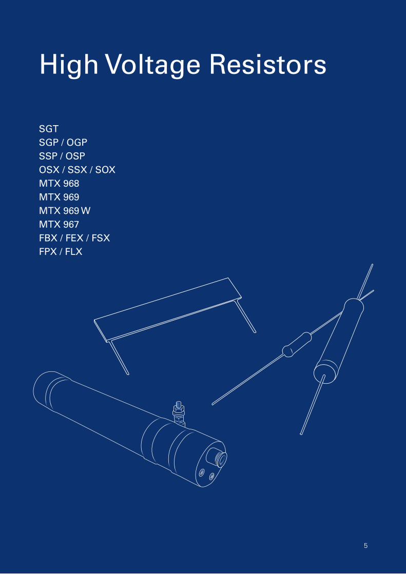
High Voltage Resistors
SGTSGP / OGPSSP / OSPOSX / SSX / SOXMTX 968MTX 969 MTX 969 WMTX 967FBX / FEX / FSXFPX / FLX
5
6 [email protected] · [email protected]
The above spec. sheet features our standard products. For further options please contact our local EBG representative or contact us directly.
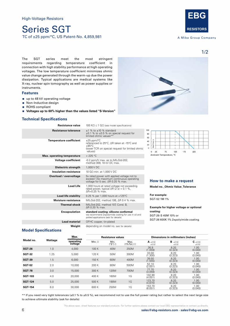
Features up to 48 kV operating voltage Non-Inductive design ROHS compliant Voltages up to 60% higher than the values listed "S-Version“
The SGT series meet the most stringent requirements regarding temperature coefficient in connection with high stability performance at high operating voltages. The low temperature coefficient minimizes ohmic value change generated through the warm-up due the power dissipation. Typical applications are medical systems like X-ray, nuclear spin tomography as well as power supplies or instruments.
How to make a request Model no._Ohmic Value_Tolerance
For example:
SGT-52 1M 1%
Example for higher voltage or optional
coating:
SGT-26-S 45M 10% or
SGT-26 600K 1% 2xpolyimide coating
Resistance value 100 KΩ ≤ 1 GΩ (see model specifications)
Resistance tolerance ±1 % to ±10 % standard ±0.1 % to ±0.5 % on special request forlimited ohmic values**
Temperature coefficient ±25 ppm/°C referenced to 25°C, ΔR taken at -15°C and+85°C (lower TCR on special request for limited ohmic values)
Max. operating temperature + 225 °C
Voltage coefficient -0.2 ppm/V max. as to MIL-Std-202, method 309, 10 kV DC max.
Dielectric strength 1,000 V DC
Insulation resistance 10 GΩ min. at 1,000 V DC
Overload / overvoltage 5x rated power with applied voltage not toexceed 1.5x maximum continuous operating voltage for 5 sec. ΔR 0.20 % max.
Load Life 1,000 hours at rated voltage not exceeding rated power, typical ΔR (2 s) = 0.1 %, ΔR=0.25 % max.
Load life stability 0.25 % per 1,000 hours at +125°C
Moisture resistance MIL-Std-202, method 106, ΔR 0.4 % max.
Thermal shock MIL-Std-202, method 107, Cond. B, ΔR 0.20 % max.
Encapsulation standard coating: silicone conformal we recommend 2xpolyimide coating for use in oil andpotted applications (ask for details)
Lead material OFHC copper, tin-plated
Weight depending on model no. (ask for details)
Technical Specifications
Model no. WattageMax.
continuous operating voltage
Resistance values Dimensions in millimeters (inches)
Min. Ω Min.("S") Ω
Max.(1% Tol.) Ω
A ±0.50 ±0.02
B ±0.50 ±0.02
C ±0.500 ±0.02
SGT-26 1.0 4,000 100 K 40M 250M 26.9(1.059)
8.20(0.323)
1.00(0.040)
SGT-32 1.25 5,000 120 K 50M 300M 33.00(1.300)
8.20(0.323)
1.00(0.040)
SGT-39 1.5 6,000 150 K 60M 400M 39.50(1.555)
8.20(0.323)
1.00(0.040)
SGT-52 2.0 10,000 200 K 80M 500M 52.10(2.051)
8.20(0.323)
1.00(0.040)
SGT-78 3.0 15,000 300 K 120M 700M 77.70(3.059)
8.20(0.323)
1.00(0.040)
SGT-103 4.0 20,000 400 K 160M 1G 102.90(4.051)
8.20(0.323)
1.00(0.040)
SGT-124 5.0 25,000 500 K 190M 1G 123.70(4.870)
8.20(0.323)
1.00(0.040)
SGT-154 6.0 30,000 600 K 250M 1G 153.70(6.051)
8.20(0.323)
1.00(0.040)
Model Specifications
** If you need very tight tolerances (±0.1 % to ±0.5 %), we recommend not to use the full power rating but rather to select the next large size
to achieve ultimate stability (ask for details)
Series SGTTC of ±25 ppm/°C, US Patent-No. 4,859,981
High-Voltage Resistors
1/2
[email protected] · [email protected]
The above spec. sheet features our standard products. For further options please contact our local EBG representative or contact us directly.
SGT 124
EBGSGT 154
SGT 103
SGT 78
SGT 52
SGT 39
SGT 26
EBG
EBG
EBG
EBG
EBG
EBG
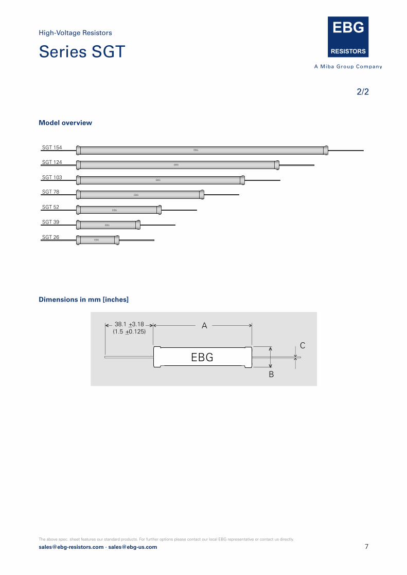
Model overview
Dimensions in mm [inches]
EBGC
B
A 38.1 +3.18 (1.5 +0.125)
2/2
Series SGTHigh-Voltage Resistors

8 [email protected] · [email protected]
The above spec. sheet features our standard products. For further options please contact our local EBG representative or contact us directly.
Series SGP / OGPTC of ±80 ppm/°C combined with precision tolerances, wide ohmic range / U.S. Patent-No. 4,859,981
High-Voltage Resistors
Features up to 48 kV operating voltage Non-Inductive design ROHS compliant Voltages up to 60% higher than the values listed –
“S“-Version
The series employs our special METOXFILM, which demons-trates excellent stability and a wide resistance range.Power and voltage ratings are for continuous operation and have all been pretested for steady-state performance as wellas momentary overload conditions.
Technical Specifications
Resistance value 100 Ω ≤ 10 GΩ (see model specifications page 2)
Resistance tolerance ±1 % to ±10 % standard down to ±0.1 % on special request for limitedohmic values
Temperature coefficient ±80 ppm/°C (at +85°C ref. to +25°C)down to ±25 ppm/°C or lower on special requestfor limited ohmic values and model no.
Max. operating temperature + 225 °C
Voltage coefficient (typical) see diagram page 3
Dielectric strength 1,000 V DC max. (25°C, 75 % relative humidity)
Insulation resistance 10 GΩ min. at 1,000 V DC
Overload / overvoltage 5x rated power at 125°C (referenced to specified power at +125°C) with applied voltage not to exceed 1.5x maximum continuous operating voltage for 5 sec. ΔR 0.5 % max.
Load life 1,000 hours at 125°C and rated power,components with 1 % tol. ΔR 0.2 % max.,extended range (“S”) ΔR = 0.5 % max.
Load life stability typical ±0.02 % per 1,000 hours
Moisture resistance MIL-Std-202, method 106, ΔR 0.4 % max.
Thermal shock MIL-Std-202, method 107, Cond. C,ΔR 0.25 % max.
Encapsulation standard: silicone coatingother coating options (like 2xpolyimide, glass) available on request
Other terminals avaiblabe screw end caps (6/32", M4, custom), golden leads with diameter 0,8 mm availabe for SGP series (ask for details)
Lead material OFHC copper, tin-plated
Weight depending on model no. (ask for details)
EBG´s Non-Inductive design offers
an outstanding advantage over other
techniques. The design incorporates a
unique method of DIGITAL TRIMMING
to value. Other less desirable methods
include an “analog“ method of abrading
and removing the resistive material, which
frequently results in a weak seation. EBG´s
patented process avoids this potential
problem.
100 80
0
60
20 40
0 25 75 125 175 225 27 5
Rat
ed P
ower
, %
120140160
all other types
SGP-154
standard wattage
Ambient Temperature, °C
How to make a request Model.no_Ohmic value_Tolerance
For example:
SGP-103 10M 1% or OGP-20 10M 5%
Example for high voltage:
SGP-154-S 300M 2% or OGP-39-S 100M 1%EBG
C
B
A 38.1 +3.18 (1.5 +0.125)
Dimensions in mm [inches]
1/3
[email protected] · [email protected]
The above spec. sheet features our standard products. For further options please contact our local EBG representative or contact us directly.
2/3
OGP series overview
SGP 148 EBG
M4
EBGSGP 20
EBGSGP 26
EBGSGP 32
EBGSGP 39
EBGSGP 52
EBGSGP 78
EBGSGP 103
EBGSGP 124
EBGSGP 154
EBGOGP 20
EBGOGP 26
EBGOGP 30
EBGOGP 39
EBGOGP 52
OGP 13EBG
All SGP and SGT types (except 148) are also available with M4 or 6/32 screw end caps.
No coating on end areas!
SGP 148 EBG
M4
EBGSGP 20
EBGSGP 26
EBGSGP 32
EBGSGP 39
EBGSGP 52
EBGSGP 78
EBGSGP 103
EBGSGP 124
EBGSGP 154
EBGOGP 20
EBGOGP 26
EBGOGP 30
EBGOGP 39
EBGOGP 52
OGP 13EBG
All SGP and SGT types (except 148) are also available with M4 or 6/32 screw end caps.
No coating on end areas!
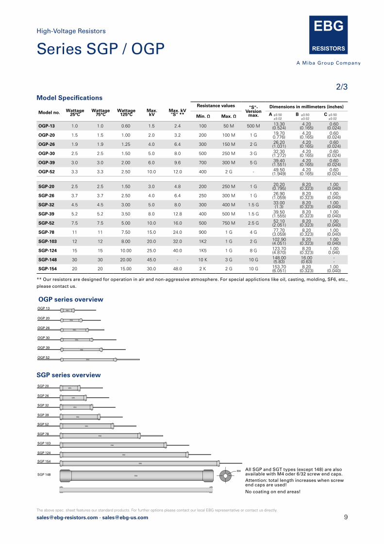
SGP series overview
Model Specifications
Model no. Wattage25°C
Wattage75°C
Wattage125°C
Max.kV
Max. kV"S" **
Resistance values "S"-Version
max.
Dimensions in millimeters (inches)
Min. Ω Max. Ω A ±0.50 ±0.02
B ±0.50 ±0.02
C ±0.50 ±0.02
OGP-13 1.0 1.0 0.60 1.5 2.4 100 50 M 500 M 13.30(0.524)
4.20(0.165)
0.60(0.024)
OGP-20 1.5 1.5 1.00 2.0 3.2 200 100 M 1 G 19.700.776)
4.20(0.165)
0.60(0.024)
OGP-26 1.9 1.9 1.25 4.0 6.4 300 150 M 2 G 26.20(1.031)
4.20(0.165)
0.60(0.024)
OGP-30 2.5 2.5 1.50 5.0 8.0 500 250 M 3 G 32.30(1.272)
4.20(0.165)
0.60(0.024)
OGP-39 3.0 3.0 2.00 6.0 9.6 700 300 M 5 G 39.40(1.551)
4.20(0.165)
0.60(0.024)
OGP-52 3.3 3.3 2.50 10.0 12.0 400 2 G - 49.50(1.949)
4.20(0.165)
0.60(0.024)
SGP-20 2.5 2.5 1.50 3.0 4.8 200 250 M 1 G 20.20(0.795)
8.20(0.323)
1.00(0.040)
SGP-26 3.7 3.7 2.50 4.0 6.4 250 300 M 1 G 26.90(1.059)
8.20(0.323)
1.00(0.040)
SGP-32 4.5 4.5 3.00 5.0 8.0 300 400 M 1.5 G 33.00(1.3)
8.20(0.323)
1.00(0.040)
SGP-39 5.2 5.2 3.50 8.0 12.8 400 500 M 1.5 G 39.50(1.555)
8.20(0.323)
1.00(0.040)
SGP-52 7.5 7.5 5.00 10.0 16.0 500 750 M 2.5 G 52.10(2.051)
8.20(0.323)
1.00(0.040)
SGP-78 11 11 7.50 15.0 24.0 900 1 G 4 G 77.70(3.059)
8.20(0.323)
1.00(0.040)
SGP-103 12 12 8.00 20.0 32.0 1K2 1 G 2 G 102.90(4.051)
8.20(0.323)
1.00(0.040)
SGP-124 15 15 10.00 25.0 40.0 1K5 1 G 8 G 123.70(4.870)
8.20(0.323)
1.000.040
SGP-148 30 30 20.00 45.0 - 10 K 3 G 10 G 148.00(5.83)
16.00(0.63)
--
SGP-154 20 20 15.00 30.0 48.0 2 K 2 G 10 G 153.70(6.051)
8.20(0.323)
1.00(0.040)
** Our resistors are designed for operation in air and non-aggressive atmosphere. For special applictions like oil, casting, molding, SF6, etc.,
please contact us.
All SGP and SGT types (except 148) are also available with M4 oder 6/32 screw end caps.Attention: total length increases when screw end caps are used!
SGP 148 EBG
M4
EBGSGP 20
EBGSGP 26
EBGSGP 32
EBGSGP 39
EBGSGP 52
EBGSGP 78
EBGSGP 103
EBGSGP 124
EBGSGP 154
EBGOGP 20
EBGOGP 26
EBGOGP 30
EBGOGP 39
EBGOGP 52
OGP 13EBG
All SGP and SGT types (except 148) are also available with M4 or 6/32 screw end caps.
No coating on end areas!
Series SGP / OGPHigh-Voltage Resistors
No coating on end areas!

10 [email protected] · [email protected]
The above spec. sheet features our standard products. For further options please contact our local EBG representative or contact us directly.
3/3 Typical Voltage Coefficient for SGP series (in ppm per volt)
Example:
SGP-154 with 100 MΩ has a typical voltage coefficient of -0,03 ppm/V.
Series SGP / OGPHigh-Voltage Resistors
[email protected] · [email protected]
The above spec. sheet features our standard products. For further options please contact our local EBG representative or contact us directly.
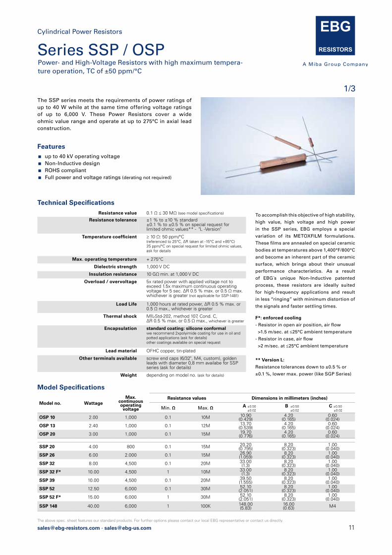
Features up to 40 kV operating voltage Non-Inductive design ROHS compliant Full power and voltage ratings (derating not required)
The SSP series meets the requirements of power ratings of up to 40 W while at the same time offering voltage ratings of up to 6,000 V. These Power Resistors cover a wide ohmic value range and operate at up to 275°C in axial lead construction.
Resistance value 0.1 Ω ≤ 30 MΩ (see model specifications)
Resistance tolerance ±1 % to ±10 % standard ±0.1 % to ±0.5 % on special request forlimited ohmic values** - "L -Version"
Temperature coefficient ≥ 10 Ω: 50 ppm/°C (referenced to 25°C, ΔR taken at -15°C and +85°C) 25 ppm/°C on special request for limited ohmic values,ask for details
Max. operating temperature + 275°C
Dielectric strength 1,000 V DC
Insulation resistance 10 GΩ min. at 1,000 V DC
Overload / overvoltage 5x rated power with applied voltage not to exceed 1.5x maximum continuous operating voltage for 5 sec. ΔR 0.5 % max. or 0.5 Ω max. whichever is greater (not applicable for SSP-148!)
Load Life 1,000 hours at rated power, ΔR 0.5 % max. or 0.5 Ω max., whichever is greater
Thermal shock MIL-Std-202, method 107, Cond. C, ΔR 0.5 % max. or 0.5 Ω max., whichever is greater
Encapsulation standard coating: silicone conformal we recommend 2xpolyimide coating for use in oil andpotted applications (ask for details)other coatings available on special request
Lead material OFHC copper, tin-plated
Other terminals available screw end caps (6/32", M4, custom), golden leads with diameter 0,8 mm availabe for SSP series (ask for details)
Weight depending on model no. (ask for details)
Technical Specifications
F*: enforced cooling
- Resistor in open air position, air flow
>1.5 m/sec. at ≤25°C ambient temperature
- Resistor in case, air flow
>2 m/sec. at ≤25°C ambient temperature
** Version L:
Resistance tolerances down to ±0.5 % or
±0.1 %, lower max. power (like SGP Series)
To accomplish this objective of high stability,
high value, high voltage and high power
in the SSP series, EBG employs a special
variation of its METOXFILM formulations.
These films are annealed on special ceramic
bodies at temperatures above 1,400°F/800°C
and become an inherent part of the ceramic
surface, which brings about their unusual
performance characteristics. As a result
of EBG´s unique Non-Inductive patented
process, these resistors are ideally suited
for high-frequency applications and result
in less “ringing” with minimum distortion of
the signals and faster settling times.
Model no. WattageMax.
continuous operating voltage
Resistance values Dimensions in millimeters (inches)
Min. Ω Max. Ω A ±0.50 ±0.02
B ±0.50 ±0.02
C ±0.500 ±0.02
OSP 10 2.00 1,000 0.1 10M 10.90(0.429)
4.20(0.165)
0.60(0.024)
OSP 13 2.40 1,000 0.1 12M 13.70(0.539)
4.20(0.165)
0.60(0.024)
OSP 20 3.00 1,000 0.1 15M 19.70(0.776)
4.20(0.165)
0.60(0.024)
SSP 20 4.00 800 0.1 15M 20.20(0.795)
8.20(0.323)
1.00(0.040)
SSP 26 6.00 2.000 0.1 15M 26.90(1.059)
8.20(0.323)
1.00(0.040)
SSP 32 8.00 4,500 0.1 20M 33.00(1.3)
8.20(0.323)
1.00(0.040)
SSP 32 F* 10.00 4,500 1 10M 33.00(1.3)
8.20(0.323)
1.00(0.040)
SSP 39 10.00 4,500 0.1 20M 39.50(1.555)
8.20(0.323)
1.00(0.040)
SSP 52 12.50 6,000 0.1 30M 52.10(2.051)
8.20(0.323)
1.00(0.040)
SSP 52 F* 15.00 6,000 1 30M 52.10(2.051)
8.20(0.323)
1.00(0.040)
SSP 148 40.00 6,000 1 100K 148.00(5.83)
16.00(0.63) M4
Model Specifications
Series SSP / OSPPower- and High-Voltage Resistors with high maximum tempera-ture operation, TC of ±50 ppm/°C
Cylindrical Power Resistors
1/3

12 [email protected] · [email protected]
The above spec. sheet features our standard products. For further options please contact our local EBG representative or contact us directly.
How to make a request Model no._Ohmic Value_Tolerance
For example:
SSP-52 68R 5% or OSP-10 150K 10%
Example for low tolerance
SSP-32-L 10R04 0.1%
OSP series overview
SSP series overview
EBGC
B
A 38.1 +3.18 (1.5 +0.125)
Dimensions in mm [inches]
Cylindrical Power Resistor Series SSP/OSP Power- and High-Voltage Resistors with high maximum temperature operation, TC of 50 ppm/°C
The above spec. sheet features our standard products. For further options please contact our local EBG representative or contact us directly.
2017.1 [email protected] · [email protected] · [email protected] Page 2 of 3
How to make a request Model no._Ohmic Value_Tolerance
For example:
SSP-52 68R 5% or OSP-10 150K 10%
Example for low tolerance
SSP-32-L 10R04 0.1%
OSP series overview
EBGSSP 52F
EBGSSP 52
EBGSSP 39
EBGSSP 32F
EBGSSP 32
EBGSSP 26
EBGSSP 20
EBGOSP 13
EBGOSP 10
EBGOSP 20
SSP 148EBG
M4
others on request
EBGSSP 52F
EBGSSP 52
EBGSSP 39
EBGSSP 32F
EBGSSP 32
EBGSSP 26
EBGSSP 20
EBGOSP 13
EBGOSP 10
EBGOSP 20
SSP 148EBG
M4
others on request
SSP series overview
EBGC
B
A 38.1 +3.18 (1.5 +0.125)
Dimensions in mm [inches]
2/3
Series SSP / OSPCylindrical Power Resistors
[email protected] · [email protected]
The above spec. sheet features our standard products. For further options please contact our local EBG representative or contact us directly.
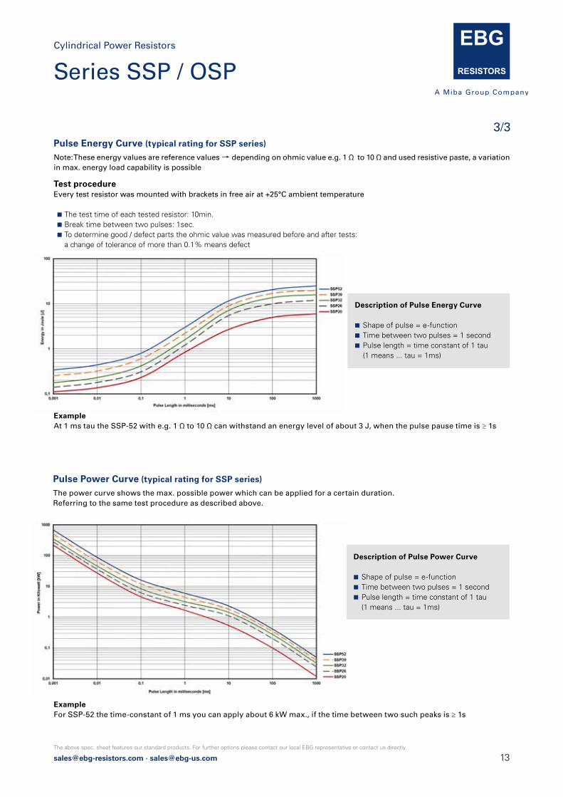
Pulse Energy Curve (typical rating for SSP series)
Note: These energy values are reference values → depending on ohmic value e.g. 1 Ω to 10 Ω and used resistive paste, a variationin max. energy load capability is possible
Pulse Power Curve (typical rating for SSP series)
The power curve shows the max. possible power which can be applied for a certain duration.Referring to the same test procedure as described above.
Test procedureEvery test resistor was mounted with brackets in free air at +25°C ambient temperature
The test time of each tested resistor: 10min. Break time between two pulses: 1sec. To determine good / defect parts the ohmic value was measured before and after tests: a change of tolerance of more than 0.1% means defect
ExampleAt 1 ms tau the SSP-52 with e.g. 1 Ω to 10 Ω can withstand an energy level of about 3 J, when the pulse pause time is ≥ 1s
ExampleFor SSP-52 the time-constant of 1 ms you can apply about 6 kW max., if the time between two such peaks is ≥ 1s
Description of Pulse Energy Curve
Shape of pulse = e-function Time between two pulses = 1 second Pulse length = time constant of 1 tau (1 means ... tau = 1ms)
Description of Pulse Power Curve
Shape of pulse = e-function Time between two pulses = 1 second Pulse length = time constant of 1 tau (1 means ... tau = 1ms)
3/3
Series SSP / OSPCylindrical Power Resistors

14 [email protected] · [email protected]
The above spec. sheet features our standard products. For further options please contact our local EBG representative or contact us directly.
Features up to 60 kV operating voltage Non-Inductive design ROHS compliant Full encapsulation over the entire resistor length All SSX types are available with M4 or 6/32 screw end caps
The OSX/SSX/SOX series meets a general set of require-ments. The products are available with a silicone or epoxy coating and feature a wide range of tolerances and tempe-rature coefficients.
Resistance value 100 Ω ≤ 50 GΩ (see model specifications page 2)higher values on special request
Resistance tolerance ±1 % to ±10 % standard±0.1 % to ±0.5 % on special request for limited ohmic values*
Temperature coefficient 100 ppm/°C standard (+85°C ref. to +25°C)down to ±5 ppm/°C on special request for limited ohmic values and tolerances
Max. working voltage see model specifications page 2
Power Rating up to 19.40 W (see model specifications page 2)
Dielectric strength ≤ 10 kV DC based on the coating
Load life stability 1,000 hours at rated power at 70°C,Δ R 0.20 % max.
Moisture resistance MIL-Std-202, method 106, Δ R 0.4 % max.
Thermal shock MIL-Std-202, method 107, Cond. A, ΔR 0.20 % max.
Encapsulation silicone or epoxy coating standard coatings: silicone or epoxy coating we recommend 2xpolyimide coating for use in oil andpotted applications (ask for details)
Other terminals avaiblabe screw end caps (6/32", M4, custom), golden leads with diameter 0,8 mm availabe for SSX / SOX series (ask for details)
Lead material OFHC copper, tin-plated
Weight depending on model no. (ask for details)
Technical SpecificationsDifferent coatings available:
- Silicone coating for ambient temperatures
up to 225°C.
- Epoxy coating for excellent humidity
protection available under the model no.
SOX.
- Polyimide for excellent protection for use in
oil and potted applications but with reduced
dielectric strength.
EBGC
B
A 38.1 +3.18 (1.5 +0.125)
How to make a request Model no._Ohmic Value_Tolerance
For example:
OSX-39 100M 0.5% or SOX-52 220M 1%
Example for higher working voltage:
SSX-39-S 20M 1%
Dimensions in mm [inches]
* In case of very tight tolerances (±0.1 % to ±0.5 %) we suggest not to use the full power rating,
but rather the next larger size to achieve ultimate stability (contact us for details)
Series OSX / SSX / SOXPower- and Precision High-Voltage Resistors TC of ±100 ppm/°C and wide ohmic range
1/2
Precision High-Voltage Resistors
[email protected] · [email protected]
The above spec. sheet features our standard products. For further options please contact our local EBG representative or contact us directly.
SOX series overview
EBGSSX 20
EBGSSX 26
EBGSSX 39
EBGSSX 52
EBGSSX 78
EBGSSX 103
EBGSSX 124
EBGSSX 154
EBGSOX 20
EBGSOX 26
EBGSOX 30
EBGSOX 39
EBGSSX 20
EBGSSX 26
EBGSSX 39
EBGSSX 52
EBGSSX 78
EBGSSX 103
EBGSSX 124
EBGSSX 154
EBGSOX 20
EBGSOX 26
EBGSOX 30
EBGSOX 39
SSX series overview
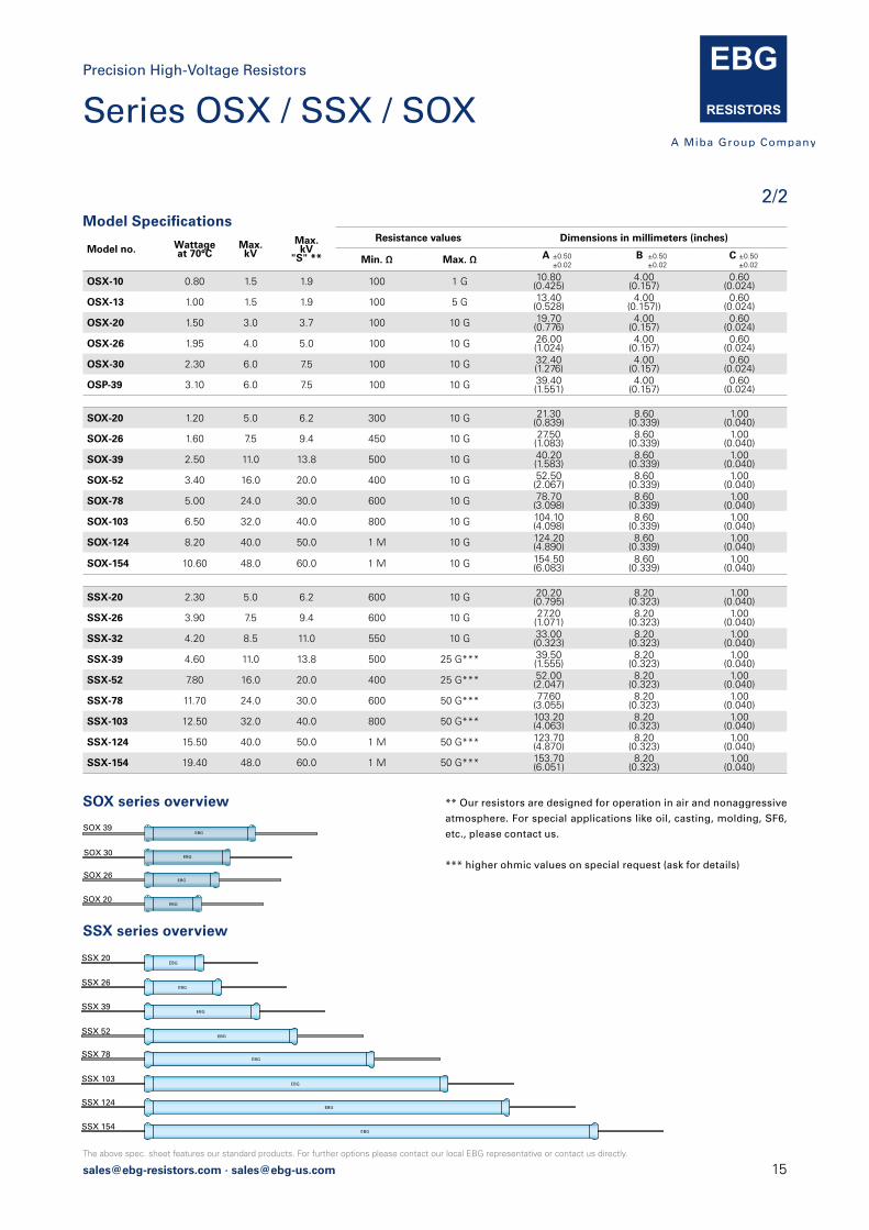
Model no. Wattageat 70°C
Max. kV
Max. kV
"S" **
Resistance values Dimensions in millimeters (inches)
Min. Ω Max. Ω A ±0.50 ±0.02
B ±0.50 ±0.02
C ±0.50 ±0.02
OSX-10 0.80 1.5 1.9 100 1 G 10.80(0.425)
4.00(0.157)
0.60(0.024)
OSX-13 1.00 1.5 1.9 100 5 G 13.40(0.528)
4.00(0.157))
0.60(0.024)
OSX-20 1.50 3.0 3.7 100 10 G 19.70(0.776)
4.00(0.157)
0.60(0.024)
OSX-26 1.95 4.0 5.0 100 10 G 26.00(1.024)
4.00(0.157)
0.60(0.024)
OSX-30 2.30 6.0 7.5 100 10 G 32.40(1.276)
4.00(0.157)
0.60(0.024)
OSP-39 3.10 6.0 7.5 100 10 G 39.40(1.551)
4.00(0.157)
0.60(0.024)
SOX-20 1.20 5.0 6.2 300 10 G 21.30(0.839)
8.60(0.339)
1.00(0.040)
SOX-26 1.60 7.5 9.4 450 10 G 27.50(1.083)
8.60(0.339)
1.00(0.040)
SOX-39 2.50 11.0 13.8 500 10 G 40.20(1.583)
8.60(0.339)
1.00(0.040)
SOX-52 3.40 16.0 20.0 400 10 G 52.50(2.067)
8.60(0.339)
1.00(0.040)
SOX-78 5.00 24.0 30.0 600 10 G 78.70(3.098)
8.60(0.339)
1.00(0.040)
SOX-103 6.50 32.0 40.0 800 10 G 104.10(4.098)
8.60(0.339)
1.00(0.040)
SOX-124 8.20 40.0 50.0 1 M 10 G 124.20(4.890)
8.60(0.339)
1.00(0.040)
SOX-154 10.60 48.0 60.0 1 M 10 G 154.50(6.083)
8.60(0.339)
1.00(0.040)
SSX-20 2.30 5.0 6.2 600 10 G 20.20(0.795)
8.20(0.323)
1.00(0.040)
SSX-26 3.90 7.5 9.4 600 10 G 27.20(1.071)
8.20(0.323)
1.00(0.040)
SSX-32 4.20 8.5 11.0 550 10 G 33.00(0.323)
8.20(0.323)
1.00(0.040)
SSX-39 4.60 11.0 13.8 500 25 G*** 39.50(1.555)
8.20(0.323)
1.00(0.040)
SSX-52 7.80 16.0 20.0 400 25 G*** 52.00(2.047)
8.20(0.323)
1.00(0.040)
SSX-78 11.70 24.0 30.0 600 50 G*** 77.60(3.055)
8.20(0.323)
1.00(0.040)
SSX-103 12.50 32.0 40.0 800 50 G*** 103.20(4.063)
8.20(0.323)
1.00(0.040)
SSX-124 15.50 40.0 50.0 1 M 50 G*** 123.70(4.870)
8.20(0.323)
1.00(0.040)
SSX-154 19.40 48.0 60.0 1 M 50 G*** 153.70(6.051)
8.20(0.323)
1.00(0.040)
Model Specifications
** Our resistors are designed for operation in air and nonaggressive
atmosphere. For special applications like oil, casting, molding, SF6,
etc., please contact us.
*** higher ohmic values on special request (ask for details)
2/2
Precision High-Voltage Resistors
Series OSX / SSX / SOX
16 [email protected] · [email protected]
The above spec. sheet features our standard products. For further options please contact our local EBG representative or contact us directly.
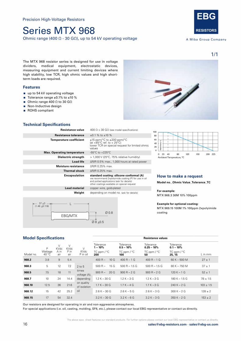
Series MTX 968Ohmic range (400 Ω - 30 GΩ), up to 54 kV operating voltage
1/1
Precision High-Voltage Resistors
Technical Specifications
How to make a request Model no._Ohmic Value_Tolerance_TC
For example:
MTX 968.3 36M 10% 100ppm
Example for optional coating:
MTX 969.15 100M 1% 100ppm 2xpolyimide
coating
Features up to 54 kV operating voltage Tolerance range ±0.1% to ±10 % Ohmic range 400 Ω to 30 GΩ Non-Inductive design ROHS compliant
The MTX 968 resistor series is designed for use in voltage dividers, medical equipment, electrostatic devices, measuring equipment and current limiting devices where high stability, low TCR, high ohmic values and high short-term loads are required.
EBG/MTXØ 0.8
Ø 8 +0.5
L 37 +3(1.46 +0.118)
Model Specifications
Resistance value 400 Ω ≤ 30 GΩ (see model specifications)
Resistance tolerance ±0.1 % to ±10 %
Temperature coefficient ±15 ppm/°C to ±200 ppm/°C (at +85°C ref. to + 25°C) lower TCR on special request for limited ohmic values
Max. Operating temperature -55°C to +225°C
Dielectric strength > 1,000 V (25°C, 75% relative humidity)
Load life ΔR/R 0.5% max., 1,000 hours at rated power
Moisture resistance ΔR/R 0.25% max.
Thermal shock ΔR/R 0.25% max.
Encapsulation standard coating: silicone conformal (A)we recommend 2xpolyimide coating (P) for use in oiland potted applications (ask for details)other coatings available on special request
Lead material copper wire, gold-plated
Weight depending on model no. (ask for details)
Our resistors are designed for operating in air and non-aggressive atmospheres.
For special applications (i.e. oil, casting, molding, SF6, etc.), please contact our local EBG representative or contact us directly.
Model no.
PWattage
40 °C
VKVdcA in air
VKVdcP in air
VKVdc
P in oil
Resistance values
Tolerance1 – 10%
TC ppm / °C200
Tolerance0.5 – 10%
TC ppm / °C100
Tolerance0.25 – 10%
TC ppm / °C50
Tolerance0.1 – 10%
TC ppm / °C25, 15 L in mm
968.2 3.8 9 5.4
2 to 5 times voltage (A), depending on quality of isolation oil
400 R – 10 G 400 R – 1 G 400 R – 1 G 60 K – 500 M 27 ± 1
968.3 5 12 7.2 500 R – 15 G 500 R – 1.5 G 500 R – 1.5 G 80 K – 750 M 37 ± 1
968.5 7.5 18 11 900 R – 20 G 900 R – 2 G 900 R – 2 G 120 K – 1 G 52 ± 1
968.7 10 24 14.4 1.2 K – 30 G 1.2 K – 3 G 1.2 K – 3 G 180 K – 1.5 G 78 ± 1.5
968.10 12.5 36 21.6 1.7 K – 30 G 1.7 K – 4 G 1.7 K – 3 G 240 K – 2 G 103 ± 1.5
968.12 15 42 25.2 2.6 K – 30 G 2.6 K – 5 G 2.6 K – 3 G 300 K – 2 G 128 ± 2
968.15 17 54 32.4 3.2 K – 30 G 3.2 K – 6 G 3.2 K – 3 G 350 K – 2 G 153 ± 2

[email protected] · [email protected]
The above spec. sheet features our standard products. For further options please contact our local EBG representative or contact us directly.
Series MTX 969 Up to 96 kV and 105 W
1/1
Precision High-Voltage / High Power Resistors
Technical Specifications
Model Specifications
B
Ø
GLD
Dimensions in mm
How to make a request Model no._Ohmic Value_Tolerance_TC
For example:
MTX 969.105 12M 10% 100ppm
Example for optional coating
MTX 969.71 100M 0.1% 100ppm
2xpolyimide coating
Resistance value 2 Ω ≤ 25 GΩ (see model specifications)
Resistance tolerance ±0.1 % to ±10 %
Temperature coefficient ±10 ppm/°C to ±200 ppm/°C (at +85°C ref. to + 25°C) lower TCR on special request for limited ohmic values
Max. Operating temperature -55°C to +225°C
Dielectric strength > 1,000 V (25°C, 75% relative humidity)
Load life ΔR/R 0.5% max., 1,000 hours at rated power
Moisture resistance ΔR/R 0.25% max.
Thermal shock ΔR/R 0.25% max.
Encapsulation standard coating: silicone conformal we recommend 2xpolyimide coating for use in oiland potted applications (ask for details)other coatings available on special request
Lead material caps, nickel-plated
Torque 1.8 Nm to 2 Nm for M4, 3.8 Nm to 4 Nm for M8
Weight depending on model no. (ask for details)
Features up to 96 kV operating voltage Tolerance range ±0.1% to ±10 % Ohmic range 2 Ω to 25 GΩ Non-Inductive design ROHS compliant
The MTX 969 resistor series is designed for use in voltage dividers, medical equipment, electrostatic devices, measuring equipment and current limiting devices where high stability, low TCR, high ohmic values and high short-term loads are required.
Model no.
PWattage
40 °C
VVoltage kV DC
Resistance values
Tolerance2 % – 10%
TC ppm / °C150, 200
Tolerance0.5 – 10%
TC ppm / °C50, 100
Tolerance0.1 – 10%
TC ppm / °C15, 25
969.11 11 24 500 R – 5 G 500 R – 1 G 50 K – 500 M
969.23 23 48 700 R – 10 G 700 R – 10 G 100 K – 1 G
969.54 54 48 2 R – 10 G 2 R – 1 G 100 K – 1 G
969.71 71 64 20 R – 15 G 20 R – 1.5 G 100 K – 1.5 G
969.105 105 96 80 R – 25 G 80 R – 2 G 100 K – 2 G
Model no. L B Ø D G
969.11 81 ± 1 14.5 ± 0.2 13.5 ± 0.5 10 ± 0.2 M4
969.23 156 ± 2 14.5 ± 0.2 13.5 ± 0.5 10 ± 0.2 M4
969.54 160 ± 2 31.5 ± 0.2 30.5 ± 0.5 18 ± 0.2 M8
969.71 210 ± 2.5 31.5 ± 0.2 30.5 ± 0.5 18 ± 0.2 M8
969.105 308 ± 3.5 31.5 ± 0.2 30.5 ± 0.5 18 ± 0.2 M8
18 [email protected] · [email protected]
The above spec. sheet features our standard products. For further options please contact our local EBG representative or contact us directly.
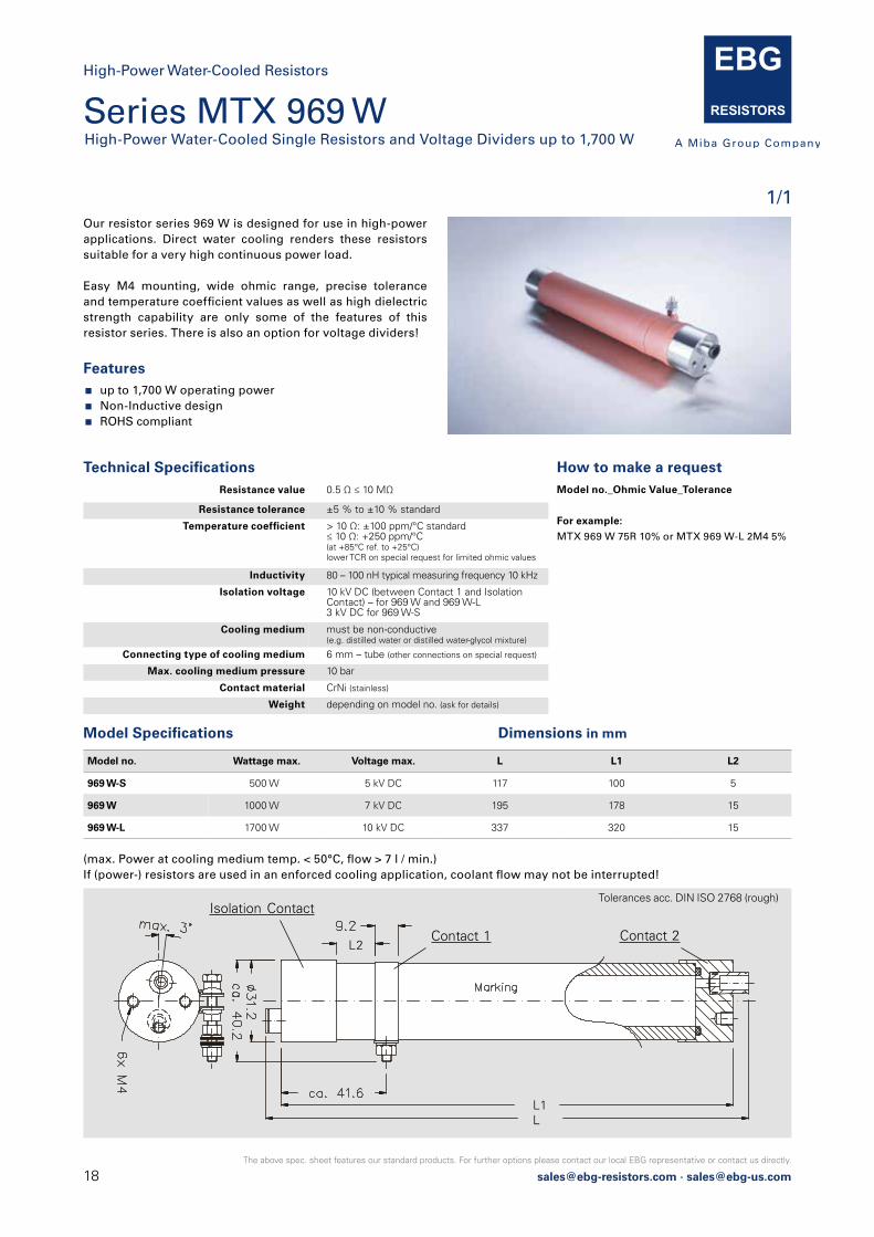
Features up to 1,700 W operating power Non-Inductive design ROHS compliant
Our resistor series 969 W is designed for use in high-power applications. Direct water cooling renders these resistors suitable for a very high continuous power load.
Easy M4 mounting, wide ohmic range, precise tolerance and temperature coefficient values as well as high dielectric strength capability are only some of the features of this resistor series. There is also an option for voltage dividers!
Model no. Wattage max. Voltage max. L L1 L2
969 W-S 500 W 5 kV DC 117 100 5
969 W 1000 W 7 kV DC 195 178 15
969 W-L 1700 W 10 kV DC 337 320 15
(max. Power at cooling medium temp. < 50°C, flow > 7 l / min.)If (power-) resistors are used in an enforced cooling application, coolant flow may not be interrupted!
How to make a request Model no._Ohmic Value_Tolerance
For example:
MTX 969 W 75R 10% or MTX 969 W-L 2M4 5%
Model Specifications Dimensions in mm
Resistance value 0.5 Ω ≤ 10 MΩ
Resistance tolerance ±5 % to ±10 % standard
Temperature coefficient > 10 Ω: ±100 ppm/°C standard≤ 10 Ω: +250 ppm/°C(at +85°C ref. to +25°C)lower TCR on special request for limited ohmic values
Inductivity 80 – 100 nH typical measuring frequency 10 kHz
Isolation voltage 10 kV DC (between Contact 1 and Isolation Contact) – for 969 W and 969 W-L3 kV DC for 969 W-S
Cooling medium must be non-conductive(e.g. distilled water or distilled water-glycol mixture)
Connecting type of cooling medium 6 mm – tube (other connections on special request)
Max. cooling medium pressure 10 bar
Contact material CrNi (stainless)
Weight depending on model no. (ask for details)
Technical Specifications
Tolerances acc. DIN ISO 2768 (rough)
LL1
Contact 1
Isolation Contact
Contact 2L2
Series MTX 969 W High-Power Water-Cooled Single Resistors and Voltage Dividers up to 1,700 W
1/1
High-Power Water-Cooled Resistors
[email protected] · [email protected]
The above spec. sheet features our standard products. For further options please contact our local EBG representative or contact us directly.
Technical Specifications
Model Specifications Dimensions in mm
100
80
0
60
20
40
0 20 40 80 120 160 175 225
Rat
ed P
ower
, %
Ambient Temperature, °C
Radial = R
A
B
C
Ø 0.8(0.031)
2.5(0.098)
Axial = A
A 36 +3(1.42 +0.118)
Ø 0.8(0.031)
30 +5(1.18 +0.197)
2.5(0.098)
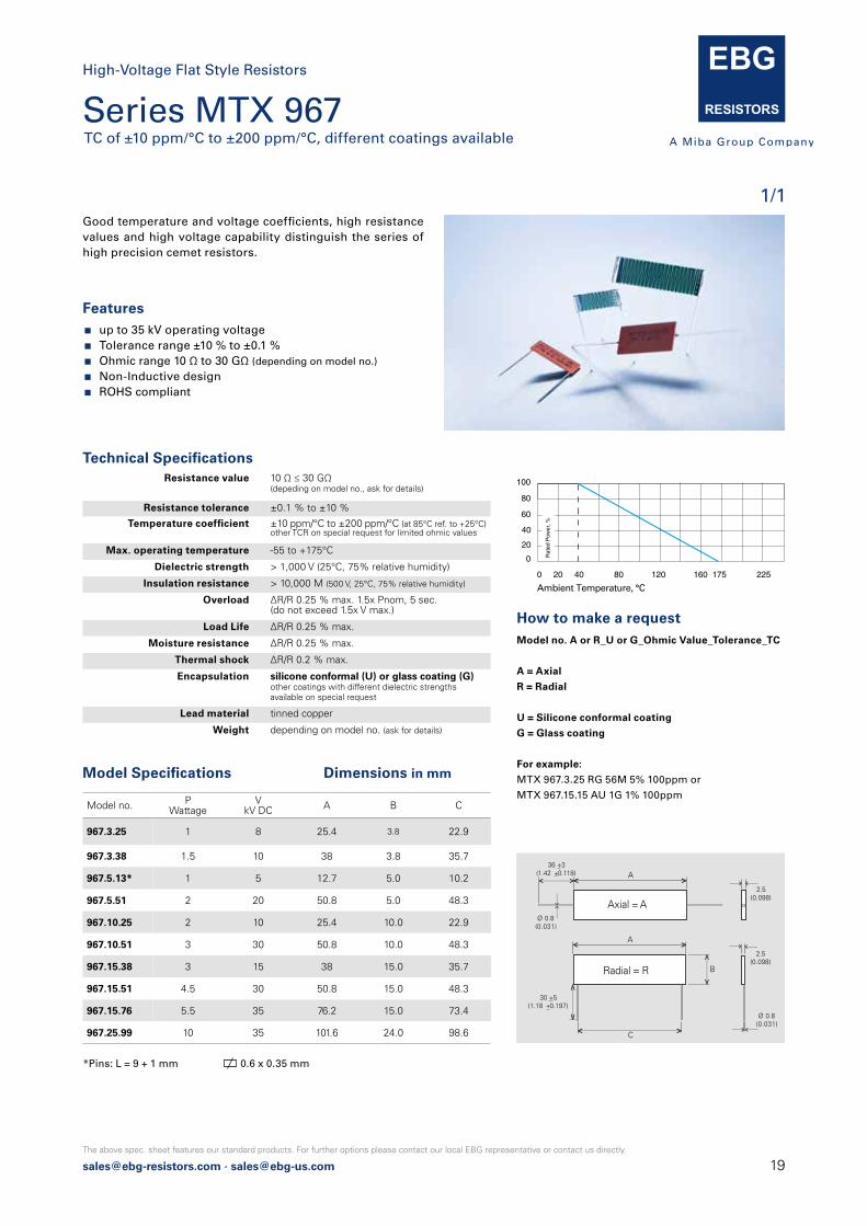
Series MTX 967 TC of ±10 ppm/°C to ±200 ppm/°C, different coatings available
1/1
High-Voltage Flat Style Resistors
Features up to 35 kV operating voltage Tolerance range ±10 % to ±0.1 % Ohmic range 10 Ω to 30 GΩ (depending on model no.)
Non-Inductive design ROHS compliant
Good temperature and voltage coefficients, high resistance values and high voltage capability distinguish the series of high precision cemet resistors.
How to make a request Model no. A or R_U or G_Ohmic Value_Tolerance_TC
A = Axial
R = Radial
U = Silicone conformal coating
G = Glass coating
For example:
MTX 967.3.25 RG 56M 5% 100ppm or
MTX 967.15.15 AU 1G 1% 100ppm
Resistance value 10 Ω ≤ 30 GΩ (depeding on model no., ask for details)
Resistance tolerance ±0.1 % to ±10 %
Temperature coefficient ±10 ppm/°C to ±200 ppm/°C (at 85°C ref. to +25°C) other TCR on special request for limited ohmic values
Max. operating temperature -55 to +175°C
Dielectric strength > 1,000 V (25°C, 75% relative humidity)
Insulation resistance > 10,000 M (500 V, 25°C, 75% relative humidity)
Overload ΔR/R 0.25 % max. 1.5x Pnom, 5 sec.(do not exceed 1.5x V max.)
Load Life ΔR/R 0.25 % max.
Moisture resistance ΔR/R 0.25 % max.
Thermal shock ΔR/R 0.2 % max.
Encapsulation silicone conformal (U) or glass coating (G) other coatings with different dielectric strengths available on special request
Lead material tinned copper
Weight depending on model no. (ask for details)
Model no. PWattage
VkV DC A B C
967.3.25 1 8 25.4 3.8 22.9
967.3.38 1.5 10 38 3.8 35.7
967.5.13* 1 5 12.7 5.0 10.2
967.5.51 2 20 50.8 5.0 48.3
967.10.25 2 10 25.4 10.0 22.9
967.10.51 3 30 50.8 10.0 48.3
967.15.38 3 15 38 15.0 35.7
967.15.51 4.5 30 50.8 15.0 48.3
967.15.76 5.5 35 76.2 15.0 73.4
967.25.99 10 35 101.6 24.0 98.6
*Pins: L = 9 + 1 mm 0.6 x 0.35 mm
20 [email protected] · [email protected]
The above spec. sheet features our standard products. For further options please contact our local EBG representative or contact us directly.
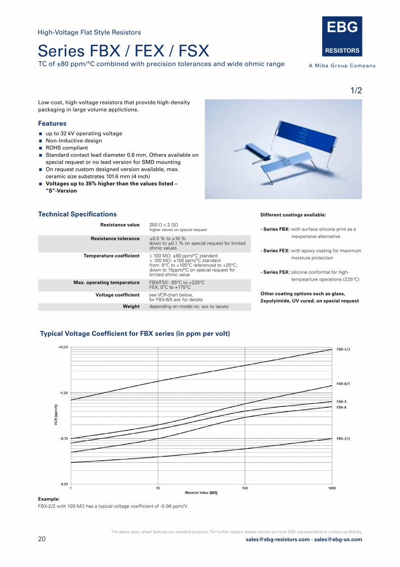
Features up to 32 kV operating voltage Non-Inductive design ROHS compliant Standard contact lead diameter 0.6 mm. Others available on
special request or no lead version for SMD mounting On request custom designed version available, max.
ceramic size substrates 101.6 mm (4 inch) Voltages up to 35% higher than the values listed –
“S“-Version
Low-cost, high-voltage resistors that provide high-densitypackaging in large volume applictions.
Resistance value 200 Ω ≤ 2 GΩ higher values on special request
Resistance tolerance ±0.5 % to ±10 % down to ±0.1 % on special request for limitedohmic values
Temperature coefficient ≤ 100 MΩ: ±80 ppm/°C standard > 100 MΩ: ±150 ppm/°C standardfrom -5°C to +105°C referenced to +25°C; down to 15ppm/°C on special request for limited ohmic value
Max. operating temperature FBX/FSX: -55°C to +225°CFEX: 0°C to +175°C
Voltage coefficient see VCR-chart below, for FBX-6/5 ask for details
Weight depending on model no. (ask for details)
Technical Specifications Different coatings available:
- Series FBX: with surface silicone print as a
inexpensive alternative
- Series FEX: with epoxy coating for maximum
moisture protection
- Series FSX: silicone conformal for high-
tempearture operations (225°C)
Other coating options such as glass,
2xpolyimide, UV cured, on special request
Typical Voltage Coefficient for FBX series (in ppm per volt)
Example:
FBX-2/2 with 100 MΩ has a typical voltage coefficient of -0.06 ppm/V.
Series FBX / FEX / FSX TC of ±80 ppm/°C combined with precision tolerances and wide ohmic range
1/2
High-Voltage Flat Style Resistors
[email protected] · [email protected]
The above spec. sheet features our standard products. For further options please contact our local EBG representative or contact us directly.
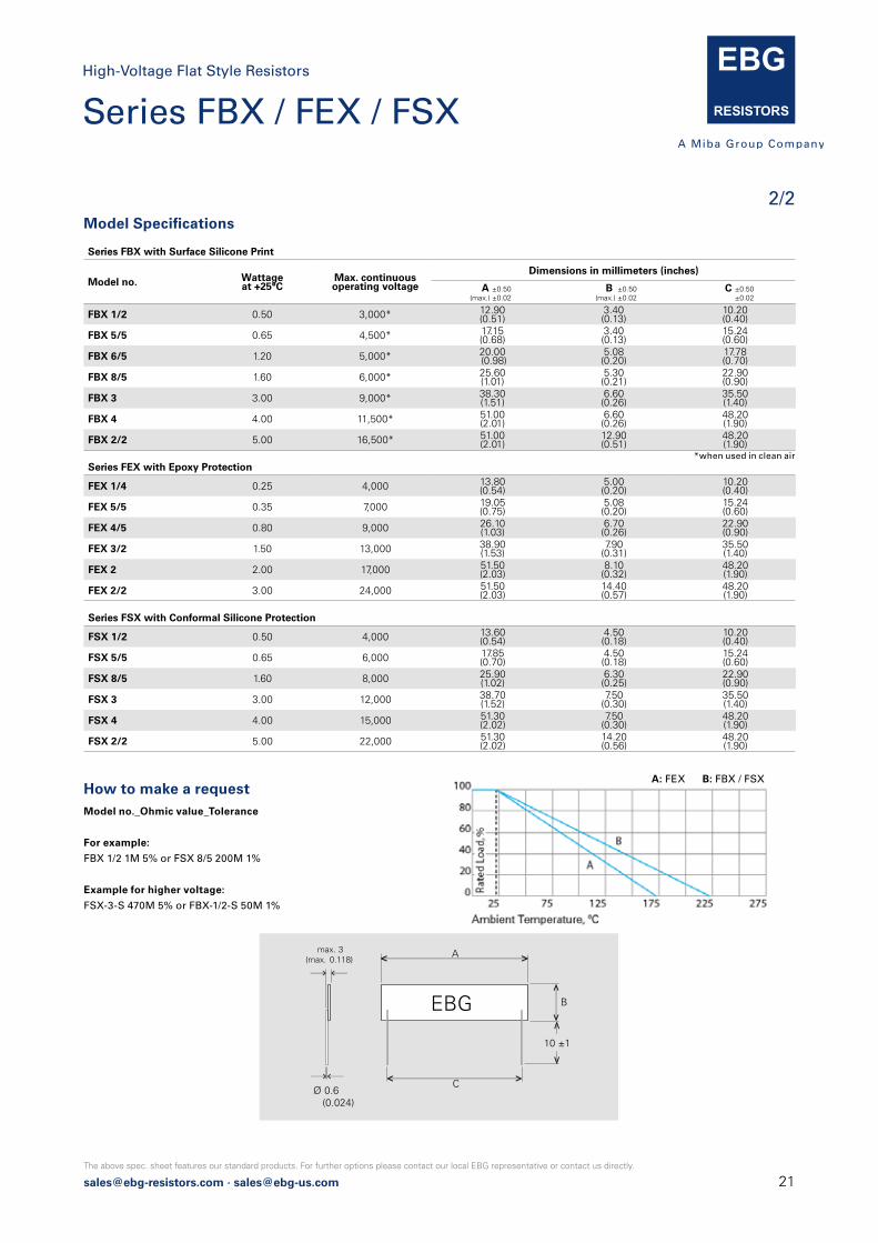
Series FBX with Surface Silicone Print
Model no. Wattageat +25°C
Max. continuous operating voltage
Dimensions in millimeters (inches)
A ±0.50 (max.) ±0.02
B ±0.50 (max.) ±0.02
C ±0.50 ±0.02
FBX 1/2 0.50 3,000* 12.90(0.51)
3.40(0.13)
10.20(0.40)
FBX 5/5 0.65 4,500* 17.15(0.68)
3.40(0.13)
15.24(0.60)
FBX 6/5 1.20 5,000* 20.00 (0.98)
5.08 (0.20)
17.78 (0.70)
FBX 8/5 1.60 6,000* 25.60(1.01)
5.30(0.21)
22.90(0.90)
FBX 3 3.00 9,000* 38.30(1.51)
6.60(0.26)
35.50(1.40)
FBX 4 4.00 11,500* 51.00(2.01)
6.60(0.26)
48.20(1.90)
FBX 2/2 5.00 16,500* 51.00(2.01)
12.90(0.51)
48.20(1.90)
Series FEX with Epoxy Protection
FEX 1/4 0.25 4,000 13.80(0.54)
5.00(0.20)
10.20(0.40)
FEX 5/5 0.35 7,000 19.05(0.75)
5.08(0.20)
15.24(0.60)
FEX 4/5 0.80 9,000 26.10(1.03)
6.70(0.26)
22.90(0.90)
FEX 3/2 1.50 13,000 38.90(1.53)
7.90(0.31)
35.50(1.40)
FEX 2 2.00 17,000 51.50(2.03)
8.10(0.32)
48.20(1.90)
FEX 2/2 3.00 24,000 51.50(2.03)
14.40(0.57)
48.20(1.90)
Series FSX with Conformal Silicone Protection
FSX 1/2 0.50 4,000 13.60(0.54)
4.50(0.18)
10.20(0.40)
FSX 5/5 0.65 6,000 17.85(0.70)
4.50(0.18)
15.24(0.60)
FSX 8/5 1.60 8,000 25.90(1.02)
6.30(0.25)
22.90(0.90)
FSX 3 3.00 12,000 38.70(1.52)
7.50(0.30)
35.50(1.40)
FSX 4 4.00 15,000 51.30(2.02)
7.50(0.30)
48.20(1.90)
FSX 2/2 5.00 22,000 51.30(2.02)
14.20(0.56)
48.20(1.90)
Model Specifications
*when used in clean air
How to make a request Model no._Ohmic value_Tolerance
For example:
FBX 1/2 1M 5% or FSX 8/5 200M 1%
Example for higher voltage:
FSX-3-S 470M 5% or FBX-1/2-S 50M 1%
EBG
A
B
max. 3(max. 0.118)
Ø 0.6 (0.024)
C
10 ±1
Series FBX / FEX / FSX
2/2
High-Voltage Flat Style Resistors
A: FEX B: FBX / FSX

22 [email protected] · [email protected]
The above spec. sheet features our standard products. For further options please contact our local EBG representative or contact us directly.
Series FPX / FLX TC of ±100 ppm/°C combined with precision tolerance and wide ohmic range
1/1
High-Voltage Flat Style Resistors
Features up to 22 kV operating voltage Series FPX / FLX printed silicone surface protection
or conformal silicone coating for high-temperature operation (225°C)
Thickness max. 3 mm (0.118 inch) for high-density packaging
Non-Inductive design ROHS compliant Voltages up to 35% higher than listed = "S"-Version
Low-cost power resistors that provide high-density packaging in large volume applications.
How to make a request Model no._Ohmic Value_Tolerance
For example:
FPX 1/2 200R 5%
Resistance value FPX: 200 Ω ≤ 2 GΩFLX: 10 Ω ≤ 1 GΩ
Resistance tolerance FPX: ±1 % to ±10 %FLX: ±0.5 % to ±10 %
Temperature coefficient ±100 ppm/°C, measured from +25°C to 85°C on special request down to ±15 ppm for specific sizes & ohmic value
Max. operating temperature -55°C to +225°C
Voltage coefficient (typically) Resistance range - ppm/V200 R – 1 M: 0.1 - 1.01 M – 100 M: 0.2 - 3.0100 M – 2.000 M: 0.5 - 10.0
Weight depending on model no. (ask for details)
Technical Specifications
Series FPX with Surface Silicone Print
Model no. Wattage
Max. continuous operating voltage
Dimensions in millimeters (inches)
A (max.)±0.50 ±0.02
B (max.) ±0.50 ±0.02
C ±0.50 ±0.02
FPX 1/2 1.50 3,000* 12.90(0.51)
3.40(0.13)
10.20(0.40)
FPX 8/5 2.50 6,000* 25.60(1.01)
5.30(0.21)
22.90(0.90)
FPX 3 4.00 9,000* 38.30(1.51)
6.60(0.26)
35.50(1.40)
FPX 4 5.00 11,500* 51.00(2.01)
6.60(0.26)
48.20(1.90)
FPX 2/2 7.50 16,500* 51.00(2.01)
12.90(0.51)
48.20(1.90)
Series FLX with Conformal Silicone Protection
FLX 1/2 1.50 300 12.90(0.51)
3.40(0.13)
10.20(0.40)
FLX 8/5 2.50 500 25.60(1.01)
5.30(0.21)
22.90(0.90)
FLX 3 4.00 800 38.30(1.51)
6.60(0.26)
35.50(1.40)
FLX 4 5.00 1,000 51.00(2.01)
6.60(0.26)
48.20(1.90)
FLX 2/2 7.50 1,000 51.00(2.01)
12.90(0.51)
48.20(1.90)
Model Specifications
*when used in clean air
EBG
A
B
max. 3(max. 0.118)
Ø 0.6 (0.024)
C
10 ±1
[email protected] · [email protected]
The above spec. sheet features our standard products. For further options please contact our local EBG representative or contact us directly.
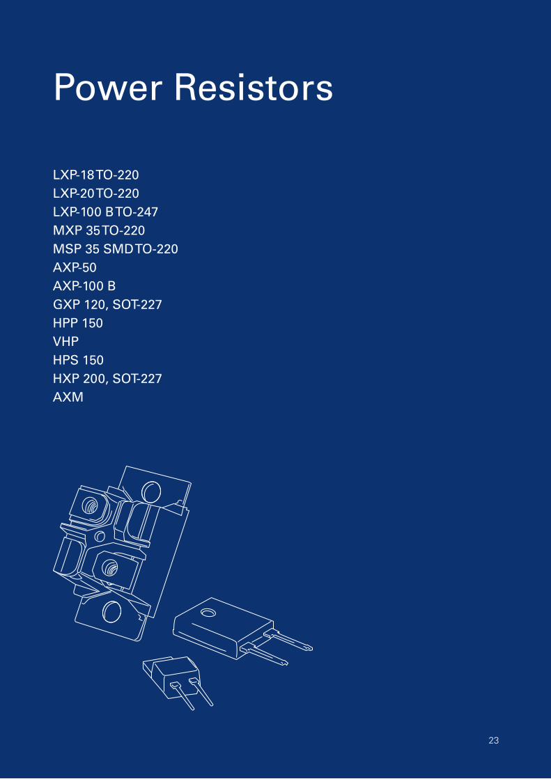
Power Resistors
LXP-18 TO-220LXP-20 TO-220LXP-100 B TO-247MXP 35 TO-220MSP 35 SMD TO-220AXP-50AXP-100 BGXP 120, SOT-227HPP 150VHPHPS 150HXP 200, SOT-227AXM
23

24 [email protected] · [email protected]
The above spec. sheet features our standard products. For further options please contact our local EBG representative or contact us directly.
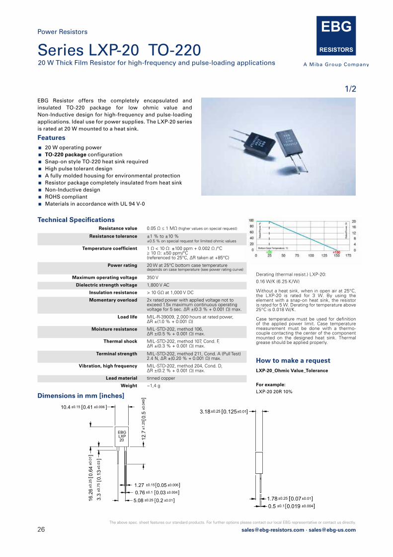
Series LXP-18 TO-22018 W Thick Film Resistor for high-frequency and pulse-loading applications
1/2
Power Resistors
Features 18 W operating power TO-220 package configuration Single-screw mounting simplifies attachment to heat sink A fully molded housing for environmental protection Resistor package completely insulated from heat sink Non-Inductive design ROHS compliant Materials in accordance with UL 94 V-0
How to make a request LXP-18_Ohmic Value_Tolerance
For example:
LXP-18 20R 10%
Technical Specifications
Dimensions in mm [inches]
Resistance value 0.05 Ω ≤ 1 MΩ (higher values on special request)
Resistance tolerance ±1 % to ±10 %±0.5 % on special request for limited ohmic values
Temperature coefficient 1 Ω < 10 Ω: ±100 ppm + 0.002 Ω/°C≥ 10 Ω: ±50 ppm/°C (referenced to 25 °C, ΔR taken at +85°C)
Power rating 18 W at 25°C bottom case temperaturedepends on case temperature (see power rating curve)
Maximum operating voltage 350 V
Dielectric strength voltage 1,800 V AC
Insulation resistance > 10 GΩ at 1,000 V DC
Momentary overload 2x rated power with applied voltage not to exceed 1.5x maximum continuous operating voltage for 5 sec. ΔR ±(0.3 % + 0.001 Ω) max.
Load life MIL -R-39009, 2,000 hours at rated power, ΔR ±(1.0 % + 0.001 Ω) max.
Moisture resistance MIL -STD-202, method 106ΔR ±(0.5 % + 0.001 Ω) max.
Thermal shock MIL -STD-202, method 107, Cond. F, ΔR ±(0.3 % + 0.001 Ω) max.
Terminal strength MIL -STD-202, method 211, Cond. A (Pull Test) 2.4 N, ΔR ±(0.2 % + 0.001 Ω) max.
Vibration, high frequency MIL -STD-202, method 204, Cond. D, ΔR ±(0.2 % + 0.001 Ω) max.
Lead material tinned copper
Mounting - torque 0.7 Nm to 0.9 Nm using a screw and a compression washer mounting technique
Weight ~1,3 g
Derating (thermal resist.) LXP-18:
0.144 W/K (6.94 K/W)
Without a heat sink, when in open air at 25°C, the LXP-18 is rated for 2.25 W. Derating for temperature above 25°C is 0.018 W/K.
Case temperature must be used for definition of the applied power limit. Case temperature measurement must be done with a thermo-couple contacting the center of the component mounted on the designed heat sink. Thermal grease should be applied properly.
3.18±0.25 0.125±0.01]
0.5 ±0.1 0.019 ±0.004]1.78 ±0.25 0.07±0.01]
10.4 ±0.15 0.41 ±0.006 ]
16.2
6±0
.25
0.64
]
3.3
±0.7
50.
13±0
.03]
12.7
±1.2
50.
5±0
.049
]
1.27 ±0.15 0.05 ±0.006]0.76 ±0.1 0.03 ±0.004]
5.08 ±0.25 0.2 ±0.01]
±0.0
1
Ø3.18 ±0.1 0.125 ±0.004 ]
3.18
±0.2
50.
125
±0.0
1] EBG
LXP18
EBG Resistor offers the completely encapsulated and insulated TO-220 package for low ohmic value and Non-Inductive design for high-frequency and pulse-loading applications. Ideal use for power supplies. The LXP-18 series is rated at 18 W mounted to a heat sink.
[email protected] · [email protected]
The above spec. sheet features our standard products. For further options please contact our local EBG representative or contact us directly.
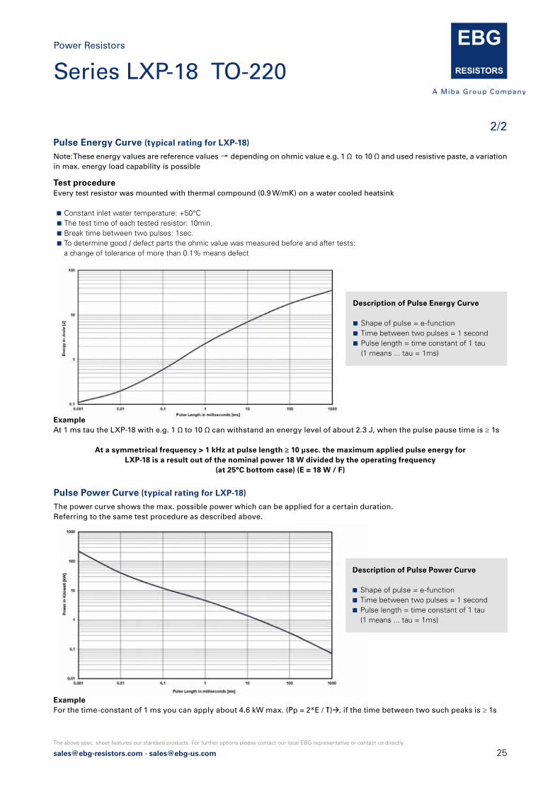
Pulse Energy Curve (typical rating for LXP-18)
Note: These energy values are reference values → depending on ohmic value e.g. 1 Ω to 10 Ω and used resistive paste, a variationin max. energy load capability is possible
Pulse Power Curve (typical rating for LXP-18)
The power curve shows the max. possible power which can be applied for a certain duration.Referring to the same test procedure as described above.
Test procedureEvery test resistor was mounted with thermal compound (0.9 W/mK) on a water cooled heatsink
Constant inlet water temperature: +50°C The test time of each tested resistor: 10min. Break time between two pulses: 1sec. To determine good / defect parts the ohmic value was measured before and after tests: a change of tolerance of more than 0.1% means defect
ExampleAt 1 ms tau the LXP-18 with e.g. 1 Ω to 10 Ω can withstand an energy level of about 2.3 J, when the pulse pause time is ≥ 1s
At a symmetrical frequency > 1 kHz at pulse length ≥ 10 μsec. the maximum applied pulse energy forLXP-18 is a result out of the nominal power 18 W divided by the operating frequency
(at 25°C bottom case) (E = 18 W / F)
ExampleFor the time-constant of 1 ms you can apply about 4.6 kW max. (Pp = 2*E / τ)à, if the time between two such peaks is ≥ 1s
Description of Pulse Energy Curve
Shape of pulse = e-function Time between two pulses = 1 second Pulse length = time constant of 1 tau (1 means ... tau = 1ms)
Description of Pulse Power Curve
Shape of pulse = e-function Time between two pulses = 1 second Pulse length = time constant of 1 tau (1 means ... tau = 1ms)
2/2
Series LXP-18 TO-220Power Resistors
26 [email protected] · [email protected]
The above spec. sheet features our standard products. For further options please contact our local EBG representative or contact us directly.
Series LXP-20 TO-22020 W Thick Film Resistor for high-frequency and pulse-loading applications
1/2
Power Resistors
Features 20 W operating power TO-220 package configuration Snap-on style TO-220 heat sink required High pulse tolerant design A fully molded housing for environmental protection Resistor package completely insulated from heat sink Non-Inductive design ROHS compliant Materials in accordance with UL 94 V-0
How to make a request LXP-20_Ohmic Value_Tolerance
For example:
LXP-20 20R 10%Dimensions in mm [inches]
EBG Resistor offers the completely encapsulated and insulated TO-220 package for low ohmic value and Non-Inductive design for high-frequency and pulse-loading applications. Ideal use for power supplies. The LXP-20 seriesis rated at 20 W mounted to a heat sink.
10.4 ±0.15 0.41 ±0.006 ]
16.2
6±0
.25
0.64
]
3.3
±0.7
50.
13±0
.03]
12.7
±1.2
50.
5±0
.049
]
1.27 ±0.15 0.05 ±0.006]0.76 ±0.1 0.03 ±0.004]
5.08 ±0.25 0.2 ±0.01]
±0.0
1
EBGLXP20
3.18±0.25 0.125±0.01]
0.5 ±0.1 0.019 ±0.004]1.78 ±0.25 0.07±0.01]
Resistance value 0.05 Ω ≤ 1 MΩ (higher values on special request)
Resistance tolerance ±1 % to ±10 %±0.5 % on special request for limited ohmic values
Temperature coefficient 1 Ω < 10 Ω: ±100 ppm + 0.002 Ω /°C≥ 10 Ω: ±50 ppm/°C (referenced to 25°C, ΔR taken at +85°C)
Power rating 20 W at 25°C bottom case temperature depends on case temperature (see power rating curve)
Maximum operating voltage 350 V
Dielectric strength voltage 1,800 V AC
Insulation resistance > 10 GΩ at 1,000 V DC
Momentary overload 2x rated power with applied voltage not to exceed 1.5x maximum continuous operatingvoltage for 5 sec. ΔR ±(0.3 % + 0.001 Ω) max.
Load life MIL -R-39009, 2,000 hours at rated power,ΔR ±(1.0 % + 0.001 Ω)
Moisture resistance MIL -STD-202, method 106, ΔR ±(0.5 % + 0.001 Ω) max.
Thermal shock MIL -STD-202, method 107, Cond. F, ΔR ±(0.3 % + 0.001 Ω) max.
Terminal strength MIL -STD-202, method 211, Cond. A (Pull Test) 2.4 N, ΔR ±(0.20 % + 0.001 Ω) max.
Vibration, high frequency MIL -STD-202, method 204, Cond. D, ΔR ±(0.2 % + 0.001 Ω) max.
Lead material tinned copper
Weight ~1,4 g
Technical Specifications
Derating (thermal resist.) LXP-20:
0.16 W/K (6.25 K/W)
Without a heat sink, when in open air at 25°C, the LXP-20 is rated for 3 W. By using the element with a snap-on heat sink, the resistor is rated for 5 W. Derating for temperature above 25°C is 0.018 W/K.
Case temperature must be used for definition of the applied power limit. Case temperature measurement must be done with a thermo-couple contacting the center of the component mounted on the designed heat sink. Thermal grease should be applied properly.

[email protected] · [email protected]
The above spec. sheet features our standard products. For further options please contact our local EBG representative or contact us directly.
2/2Pulse Energy Curve (typical rating for LXP-20)
Note: These energy values are reference values → depending on ohmic value e.g. 1 Ω to 10 Ω and used resistive paste, a variationin max. energy load capability is possible
Pulse Power Curve (typical rating for LXP-20)
The power curve shows the max. possible power which can be applied for a certain duration.Referring to the same test procedure as described above.
Test procedureEvery test resistor was mounted with thermal compound (0.9 W/mK) on a water cooled heatsink
Constant inlet water temperature: +50°C The test time of each tested resistor: 10min. Break time between two pulses: 1sec. To determine good / defect parts the ohmic value was measured before and after tests: a change of tolerance of more than 0.1% means defect
ExampleAt 1 ms tau the LXP-20 with e.g. 1 Ω to 10 Ω can withstand an energy level of about 3 J, when the pulse pause time is ≥ 1s
At a symmetrical frequency > 1 kHz at pulse length ≥ 10 μsec. the maximum applied pulse energy forLXP-20 is a result out of the nominal power 20 W divided by the operating frequency
(at 25°C bottom case) (E = 20 W / F)
ExampleFor the time-constant of 1 ms you can apply about 6 kW max. (Pp = 2*E / τ)à, if the time between two such peaks is ≥ 1s
Description of Pulse Energy Curve
Shape of pulse = e-function Time between two pulses = 1 second Pulse length = time constant of 1 tau (1 means ... tau = 1ms)
Description of Pulse Power Curve
Shape of pulse = e-function Time between two pulses = 1 second Pulse length = time constant of 1 tau (1 means ... tau = 1ms)
Series LXP-20 TO-220Power Resistors

28 [email protected] · [email protected]
The above spec. sheet features our standard products. For further options please contact our local EBG representative or contact us directly.
How to make a request LXP-100 B_Ohmic Value_Tolerance
For example:
LXP-100 B 20R 10%
Derating (thermal resist.) LXP-100 B:
0.66 W/K (1.5 K/W)
Without a heat sink, when in open air at 25°C,
the LXP-100 B is rated for 3 W. Derating for
temperature above 25°C is 0.023 W/K.
Case temperature must be used for definition
of the applied power limit. Case temperature
measurement must be done with a thermo-
couple contacting the center of the component
mounted on the designed heat sink. Thermal
grease should be applied properly.
This value is only applicable when using thermal
conduction to heat sink Rth-cs <0.025 K/W.
This value can be attained by using a thermal
transfer compound with a heat conductivity
of 1 W/mK. The flatness of the cooling plate
must be bettern than 0.05 mm overall. Surface
roughness should not exceed 6.4 µm.
EBG Resistor offers the completely encapsulated and insulated TO-247 package for low ohmic value and Non-Inductive design for high-frequency and pulse-loading applications. Ideal use for power supplies. The LXP-100 B series is rated at 100 W mounted to a heat sink.
100 W operating power TO-247 package configuration Single-screw mounting simplifies attachment to heat sink A fully molded housing for environmental protection Resistor package completely insulated from heat sink Tube packing available (packing unit: 35 pcs. / tube) For perfect heat dissipation, the use of mounting clamps
is suggested (ask for details)
Non-Inductive design ROHS compliant Materials in accordance with UL 94 V-0
Features
Resistance value 0.05 Ω ≤ 1 MΩ (higher values on special request)
Resistance tolerance ±10 % to ±1 %
Temperature coefficient > 10 Ω: ±50 ppm/°C referenced to 25°C, ΔR taken at +105°C(other TCR on special request for limited ohmic values)
Power rating 100 W at 25°C bottom case temperaturederated to 0 W at 175°C
Short time overload 1.5x rated power with applied voltage not to exceed 1.5x V max. for 5 seconds,ΔR < ±(0.50 % + 0.0005 Ω)
Maximum operating voltage 350 V, max. 500 V on special request
Insulation resistance > 10 GΩ at 1,000 V DC
Dielectric strength voltage 1,800 V AC
Dieletric strength MIL -STD-202, method 301 (1,800 V AC, 60 sec.)ΔR < ±(0.15 % + 0.0005 Ω)
Load life MIL -R-39009D 4.8.13, 2,000 hours at rated power, ΔR < ±(1.0 % + 0.0005 Ω)
Moisture resistance -10°C to +65°C, RH > 90 % cycle 240 h,ΔR < ±(0.50 % + 0.0005 Ω)
Thermal shock MIL -STD-202, method 107, Cond. F, ΔR < ±(0.50 % + 0.0005 Ω)
Terminal strength MIL -STD-202, method 211, Cond. A (Pull Test) 2.4 N ΔR < ±(0.20 % + 0.0005 Ω)
Vibration, high frequency MIL -STD-202, method 204, Cond. D, ΔR < ±(0.40 % + 0.0005 Ω)
Inductance (serial) typical 20 nH
Lead material tinned copper
Mounting - torque 0.7 Nm to 0.9 Nm M4 using a M3 screw and a compression wahser mounting technique
Weight ~4 g
Technical Specifications
Series LXP-100 B TO-247100 W Thick Film Resistor for high-frequency and pulse-loading applicationsVersion B for enforced mechanical stability
1/2
Power Resistors
[email protected] · [email protected]
The above spec. sheet features our standard products. For further options please contact our local EBG representative or contact us directly.
Dimensions in mm [inches]
4.95 ±0.26 0.195 ±0.01]
0.8 ±0.25 0.031 ±0.01]2.41 ±0.25 0.095 ±0.01]
Ø3.63 ±0.1 0.143±0.004]15.75 ±0.25 0.62 ±0.01]
5.33
±0.2
50.
21±0
.01]
20.7
±0.2
50.
815
]
2.8
±0.7
50.
11±0
.03]
14.5
±1.2
50.
57±0
.049
]
3.63 ±0.2 0.143 ±0.008]1.52 ±0.15 0.06 ±0.006]
10.16 ±0.25 0.4 ±0.01]
±0.0
1
EBGLXP100
0,01
0,1
1
10
100
1000
0,001 0,01 0,1 1 10 100 1000
En
erg
y in
Jo
ule
[J]
Pulse Length in milliseconds [ms]
*
* longer contacts availabe (ask for details)
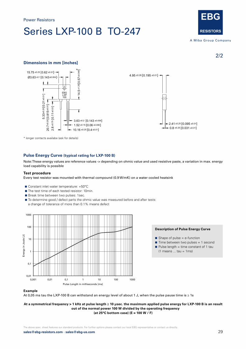
Description of Pulse Energy Curve
Shape of pulse = e-function Time between two pulses = 1 second Pulse length = time constant of 1 tau (1 means ... tau = 1ms)
Pulse Energy Curve (typical rating for LXP-100 B)
Note: These energy values are reference values -> depending on ohmic value and used resistive paste, a variation in max. energy load capability is possible
Test procedureEvery test resistor was mounted with thermal compound (0.9 W/mK) on a water cooled heatsink
Constant inlet water temperature: +50°C The test time of each tested resistor: 10min. Break time between two pulses: 1sec. To determine good / defect parts the ohmic value was measured before and after tests: a change of tolerance of more than 0.1% means defect
ExampleAt 0,05 ms tau the LXP-100 B can withstand an energy level of about 1 J, when the pulse pause time is ≥ 1s
At a symmetrical frequency > 1 kHz at pulse length ≥ 10 µsec. the maximum applied pulse energy for LXP-100 B is an result out of the normal power 100 W divided by the operating frequency
(at 25°C bottom case) (E = 100 W / F)
2/2
Power Resistors
Series LXP-100 B TO-247
30 [email protected] · [email protected]
The above spec. sheet features our standard products. For further options please contact our local EBG representative or contact us directly.
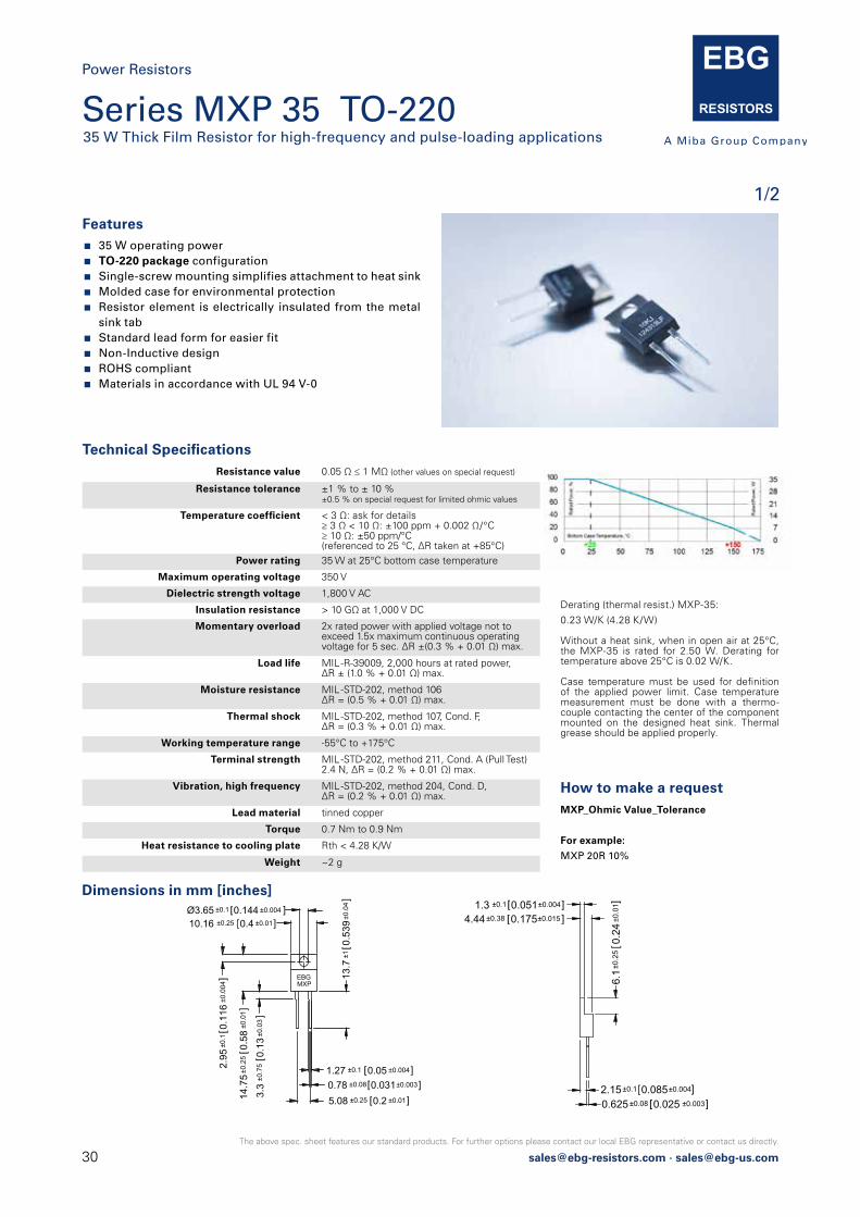
Series MXP 35 TO-22035 W Thick Film Resistor for high-frequency and pulse-loading applications
1/2
Power Resistors
Features 35 W operating power TO-220 package configuration Single-screw mounting simplifies attachment to heat sink Molded case for environmental protection Resistor element is electrically insulated from the metal
sink tab Standard lead form for easier fit Non-Inductive design ROHS compliant Materials in accordance with UL 94 V-0
How to make a request MXP_Ohmic Value_Tolerance
For example:
MXP 20R 10%
Dimensions in mm [inches]
Technical Specifications Resistance value 0.05 Ω ≤ 1 MΩ (other values on special request)
Resistance tolerance ±1 % to ± 10 %±0.5 % on special request for limited ohmic values
Temperature coefficient < 3 Ω: ask for details≥ 3 Ω < 10 Ω: ±100 ppm + 0.002 Ω/°C≥ 10 Ω: ±50 ppm/°C (referenced to 25 °C, ΔR taken at +85°C)
Power rating 35 W at 25°C bottom case temperature
Maximum operating voltage 350 V
Dielectric strength voltage 1,800 V AC
Insulation resistance > 10 GΩ at 1,000 V DC
Momentary overload 2x rated power with applied voltage not to exceed 1.5x maximum continuous operating voltage for 5 sec. ΔR ±(0.3 % + 0.01 Ω) max.
Load life MIL -R-39009, 2,000 hours at rated power, ΔR ± (1.0 % + 0.01 Ω) max.
Moisture resistance MIL -STD-202, method 106ΔR = (0.5 % + 0.01 Ω) max.
Thermal shock MIL -STD-202, method 107, Cond. F, ΔR = (0.3 % + 0.01 Ω) max.
Working temperature range -55°C to +175°C
Terminal strength MIL -STD-202, method 211, Cond. A (Pull Test) 2.4 N, ΔR = (0.2 % + 0.01 Ω) max.
Vibration, high frequency MIL -STD-202, method 204, Cond. D, ΔR = (0.2 % + 0.01 Ω) max.
Lead material tinned copper
Torque 0.7 Nm to 0.9 Nm
Heat resistance to cooling plate Rth < 4.28 K/W
Weight ~2 g
Derating (thermal resist.) MXP-35:
0.23 W/K (4.28 K/W)
Without a heat sink, when in open air at 25°C, the MXP-35 is rated for 2.50 W. Derating for temperature above 25°C is 0.02 W/K.
Case temperature must be used for definition of the applied power limit. Case temperature measurement must be done with a thermo-couple contacting the center of the component mounted on the designed heat sink. Thermal grease should be applied properly.
4.44±0.38 0.175±0.015 ]
0.625 ±0.08 0.025 ±0.003]2.15±0.1 0.085±0.004]
1.3 ±0.1 0.051±0.004]
6.1±
0.25
0.24
±0.0
1 ]
10.16 ±0.25 0.4 ±0.01]
14.7
5±0
.25
0.58
]
3.3
±0.7
50.
13±0
.03]
13.7
±10.
539±
0.04
]
1.27 ±0.1 0.05 ±0.004]0.78 ±0.08 0.031±0.003]5.08 ±0.25 0.2 ±0.01]
±0.0
1
Ø3.65 ±0.1 0.144 ±0.004 ]
2.95
±0.1
0.11
6±0
.004
] EBGMXP

[email protected] · [email protected]
The above spec. sheet features our standard products. For further options please contact our local EBG representative or contact us directly.
Pulse Energy Curve (typical rating for MXP 35)
Note: These energy values are reference values → depending on ohmic value e.g. 1 Ω to 10 Ω and used resistive paste, a variationin max. energy load capability is possible
Pulse Power Curve (typical rating for MXP 35)
The power curve shows the max. possible power which can be applied for a certain duration.Referring to the same test procedure as described above.
Test procedureEvery test resistor was mounted with thermal compound (0.9 W/mK) on a water cooled heatsink
Constant inlet water temperature: +50°C The test time of each tested resistor: 10min. Break time between two pulses: 1sec. To determine good / defect parts the ohmic value was measured before and after tests: a change of tolerance of more than 0.1% means defect
ExampleAt 1 ms tau the MXP 35 with e.g. 1 Ω to 10 Ω can withstand an energy level of about 0.9 J, when the pulse pause time is ≥ 1s
At a symmetrical frequency > 1 kHz at pulse length ≥ 10 μsec. the maximum applied pulse energy forMXP 35 is a result out of the nominal power 35 W divided by the operating frequency
(at 25°C bottom case) (E = 35 W / F)
ExampleFor the time-constant of 1 ms you can apply about 1.8 kW max. (Pp = 2*E / τ)à, if the time between two such peaks is ≥ 1s
Description of Pulse Energy Curve
Shape of pulse = e-function Time between two pulses = 1 second Pulse length = time constant of 1 tau (1 means ... tau = 1ms)
Description of Pulse Power Curve
Shape of pulse = e-function Time between two pulses = 1 second Pulse length = time constant of 1 tau (1 means ... tau = 1ms)
2/2
Power Resistors
Series MXP 35 TO-220

32 [email protected] · [email protected]
The above spec. sheet features our standard products. For further options please contact our local EBG representative or contact us directly.
Power Resistors
Features 35 W operating power SMD TO-220 package configuration Molded case for environmental protection Resistor element is electrically insulated from the metal
sink tab Non-Inductive design ROHS compliant Materials in accordance with UL 94 V-0 High soldering version available
Dimensions in mm
Technical Specifications Resistance value 0.1 Ω ≤ 1 MΩ (other values on special request)
Resistance tolerance ±1 % to ± 10 % ±0.5 % on special request for limited ohmic values
Temperature coefficient < 3 Ω: ask for details≥ 3 Ω < 10 Ω: ±100 ppm + 0.002 Ω/°C≥ 10 Ω: ±50 ppm/°C (referenced to 25 °C, ΔR taken at +85°C)
Power rating 35 W at 25°C bottom case temperature
Maximum operating voltage 350 V
Dielectric strength voltage 1,800 V AC
Insulation resistance > 10 GΩ at 1,000 V DC
Momentary overload 2x rated power with applied voltage not to exceed 1.5x maximum continuous operating voltage for 5 sec. ΔR ±(0.3 % + 0.01 Ω) max.
Load life MIL -R-39009, 2,000 hours at rated power, ΔR ±(1.0 % + 0.01 Ω) max.
Moisture resistance MIL -STD-202, method 106ΔR = (0.5 % + 0.01 Ω) max.
Thermal shock MIL -STD-202, method 107, Cond. F, ΔR = (0.3 % + 0.01 Ω) max.
Working temperature range -55°C to +175°C
Terminal strength MIL -STD-202, method 211, Cond. A (Pull Test) 2.4 N, ΔR = (0.2 % + 0.01 Ω) max.
Vibration, high frequency MIL -STD-202, method 204, Cond. D, ΔR = (0.2 % + 0.01 Ω) max.
Lead material nickel-plated copper, dip-tinned
Ground plate material german silver; alternative material on request
Heat resistance to cooling plate Rth < 4.28 K/W
Weight ~1,4 g
Derating (thermal resist.) MSP-35:
0.23 W/K (4.28 K/W)
Case temperature must be used for definition of the applied power limit. Case temperature measurement must be done with a thermo-couple contacting the center of the component mounted on the designed heat sink. Thermal grease should be applied properly.
35 W Film Power Resistor for surface mount including metal tab.
Soldering Template
Tolerances ±0.2 unless otherwise noted!TO-220 style power package for SMD applcations 35 W power rating at 25°C case temerature.
Flatness of ground plate to contacts <0.1mm
How to make a request MSP_Ohmic Value_Tolerance
For example:
MSP 39R 5%
Example for higher solder profile:
MHP 560R 1%
Series MSP 35 SMD TO-220(MHP 35 for high temperature soldering)35 W Thick Film Resistor for surface mount including Metal Tab
1/2
Soldering Note:During surface mount soldering, the soldering temp. profile must not cause the metal tab of this device to exceed 215°C. For solder profile temp. above 215°C up to max. 260°C, please use our alternative type MHP 35 SMD TO-220.

[email protected] · [email protected]
The above spec. sheet features our standard products. For further options please contact our local EBG representative or contact us directly.
Pulse Energy Curve (typical rating for MSP 35)
Note: These energy values are reference values → depending on ohmic value e.g. 1 Ω to 10 Ω and used resistive paste, a variationin max. energy load capability is possible
Pulse Power Curve (typical rating for MSP 35)
The power curve shows the max. possible power which can be applied for a certain duration.Referring to the same test procedure as described above.
Test procedureEvery test resistor was mounted with thermal compound (0.9 W/mK) on a water cooled heatsink
Constant inlet water temperature: +50°C The test time of each tested resistor: 10min. Break time between two pulses: 1sec. To determine good / defect parts the ohmic value was measured before and after tests: a change of tolerance of more than 0.1% means defect
ExampleAt 1 ms tau the MSP 35 with e.g. 1 Ω to 10 Ω can withstand an energy level of about 0.9 J, when the pulse pause time is ≥ 1s
At a symmetrical frequency > 1 kHz at pulse length ≥ 10 μsec. the maximum applied pulse energy forMSP 35 is a result out of the nominal power 35 W divided by the operating frequency
(at 25°C bottom case) (E = 35 W / F)
ExampleFor the time-constant of 1 ms you can apply about 1.8 kW max. (Pp = 2*E / τ)à, if the time between two such peaks is ≥ 1s
Description of Pulse Energy Curve
Shape of pulse = e-function Time between two pulses = 1 second Pulse length = time constant of 1 tau (1 means ... tau = 1ms)
Description of Pulse Power Curve
Shape of pulse = e-function Time between two pulses = 1 second Pulse length = time constant of 1 tau (1 means ... tau = 1ms)
2/2
Power Resistors
Series MSP 35 SMD TO-220

34 [email protected] · [email protected]
The above spec. sheet features our standard products. For further options please contact our local EBG representative or contact us directly.
The new design with its non-inductive thick film Metal OxideTechnology prevents potential problems with clearance and creeping distance from terminal to base plate by means of flexible connecting leads.
Technical Specifications Resistance value 1 Ω ≤ 1 MΩ
Resistance tolerance ±1 % to ±10 %
Temperature coefficient ±50 ppm/°C to ±250 ppm/°C (at +85°C ref. to + 25°C)
Power rating up to 50 W at 85°C bottom case temperature (see configurations)
Maximum working voltage 500 V (up to 1,000 V DC on special request = "S"-version)
Electric strength voltage 5 kV DC (3 kV AC, higher values on special request)between terminal and case
Internal electric strength between R1 & R2 5 kV DC
Isolation voltage between R1 & R2 500 V (higher on special request)
Working temperatur range -55°C to +155°C
Mounting - torque 1.0 Nm to 1.2 Nm
Standard cable length 100 mm (other lengths on special request)
Standard cable type 4GKW, 0,5 mm2, black
Weight ~22 g
Derating (thermal resist.) AXP-50:
0.995 W/K (1.005 K/W) (for conf. 1, 2 and 3)
Best results can be reached by using a thermal transfer compound with a heat conductivity of at least 1 W/mK. The flatness of the cooling plate must be better than 0.05 mm overall. Surface roughness should not exceed 6.4 μm.
Features 1x 50 W / 2x 20 W / 3x 10 W operating power Non-Inductive design ROHS compliant Materials in accordance with UL 94 V-0
This unique design allows you to use this elements in the following areas: variable speed drives, power supplies, control devices, telecommunications, robotics, motor controls and other switching devices.
Suggested Mounting Procedure:
1.) Position component and press down by hand
2.) Fix both mounting screws (M3) with 0.1 to 0.2 Nm torque
3.) Apply final torque to mounting screws of 1.0 to 1.2 Nm
How to make a request AXP-50-Configuration_Ohmic Value_
Tolerance
For example:
AXP-50-1 1K 10% or AXP-50-4 2x50R 5%
Exampe for higher working voltage:
AXP-50-1-S 55K 5%
7.4±0.5 0.291±0.02 ]
25 ±0.2 0.984 ±0.008]
10.4
±0.5
0.40
9±0
.02]
18.5±0.2 0.728±0.008]
6.5
±0.2
0.25
6±0
.008
]
102.5±2.5 4.035±0.1]
10.25±0.25 0.403±0.01]
6 ±0.2 0.236±0.008]4 ±0.2 0.157±0.008]
Version 5: ohmic value between contact 2 and 4 = 3mΩ
Configurations (P / package)
50W
21
1
50W41
2
50W1 2
3 43
2 x 20W
R2
R1
3
1
4
2
4
2 x 20W
R2
R1
3 4
1 2
5
3 x 10W
R3
R2
3 4
6
R11 2
Dimensions in mm [inches]
Power Resistors
Series AXP-5050 W Power Resistor with four wire terminals
1/1
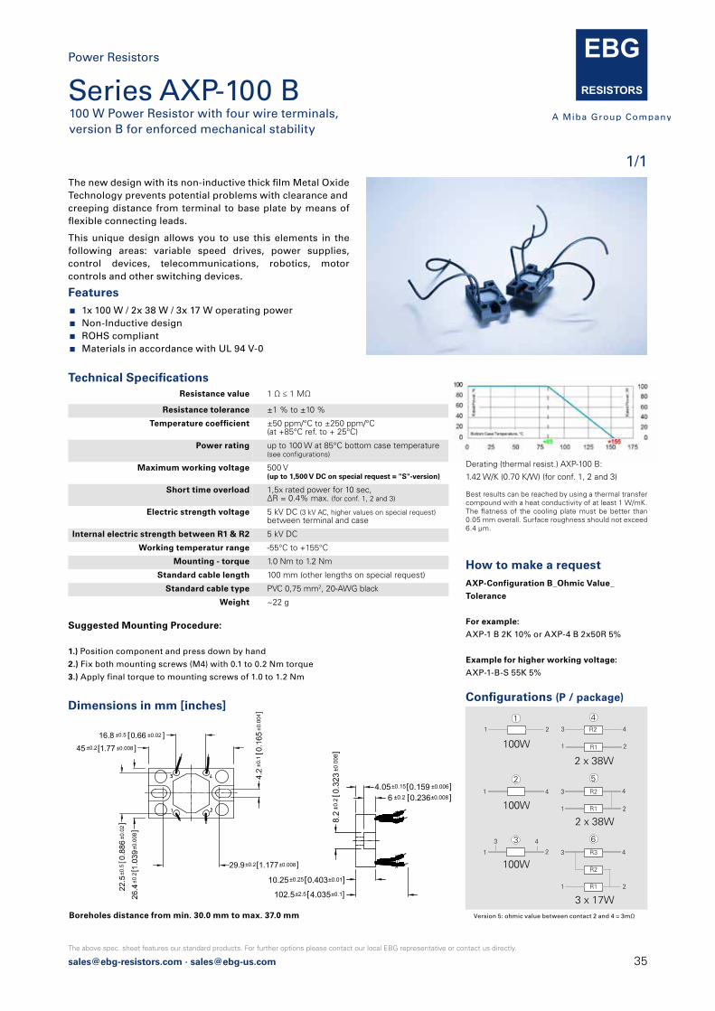
[email protected] · [email protected]
The above spec. sheet features our standard products. For further options please contact our local EBG representative or contact us directly.
The new design with its non-inductive thick film Metal OxideTechnology prevents potential problems with clearance andcreeping distance from terminal to base plate by means of flexible connecting leads.
Technical Specifications Resistance value 1 Ω ≤ 1 MΩ
Resistance tolerance ±1 % to ±10 %
Temperature coefficient ±50 ppm/°C to ±250 ppm/°C (at +85°C ref. to + 25°C)
Power rating up to 100 W at 85°C bottom case temperature (see configurations)
Maximum working voltage 500 V(up to 1,500 V DC on special request = "S"-version)
Short time overload 1,5x rated power for 10 sec, ΔR = 0.4% max. (for conf. 1, 2 and 3)
Electric strength voltage 5 kV DC (3 kV AC, higher values on special request)between terminal and case
Internal electric strength between R1 & R2 5 kV DC
Working temperatur range -55°C to +155°C
Mounting - torque 1.0 Nm to 1.2 Nm
Standard cable length 100 mm (other lengths on special request)
Standard cable type PVC 0,75 mm2, 20-AWG black
Weight ~22 g
Derating (thermal resist.) AXP-100 B:
1.42 W/K (0.70 K/W) (for conf. 1, 2 and 3)
Best results can be reached by using a thermal transfer compound with a heat conductivity of at least 1 W/mK. The flatness of the cooling plate must be better than 0.05 mm overall. Surface roughness should not exceed 6.4 μm.
Features 1x 100 W / 2x 38 W / 3x 17 W operating power Non-Inductive design ROHS compliant Materials in accordance with UL 94 V-0
This unique design allows you to use this elements in the following areas: variable speed drives, power supplies, control devices, telecommunications, robotics, motor controls and other switching devices.
Suggested Mounting Procedure:
1.) Position component and press down by hand
2.) Fix both mounting screws (M4) with 0.1 to 0.2 Nm torque
3.) Apply final torque to mounting screws of 1.0 to 1.2 Nm
How to make a request AXP-Configuration B_Ohmic Value_
Tolerance
For example:
AXP-1 B 2K 10% or AXP-4 B 2x50R 5%
Example for higher working voltage:
AXP-1-B-S 55K 5%
16.8 ±0.5 0.66 ±0.02 ]
45 ±0.2 1.77 ±0.008 ]
22.5
±0.5
0.88
6±0
.02]
29.9±0.2 1.177±0.008]
102.5±2.5 4.035±0.1]
10.25±0.25 0.403±0.01]
6 ±0.2 0.236±0.008]4.05±0.15 0.159 ±0.006]
Configurations (P / package)
Version 5: ohmic value between contact 2 and 4 = 3mΩ
100W
21
1
100W41
2
100W1 2
3 43
2 x 38W
R2
R1
3
1
4
2
4
2 x 38W
R2
R1
3 4
1 2
5
3 x 17W
R3
R2
3 4
6
R11 2
Dimensions in mm [inches]
Power Resistors
Series AXP-100 B100 W Power Resistor with four wire terminals, version B for enforced mechanical stability
1/1
Boreholes distance from min. 30.0 mm to max. 37.0 mm

36 [email protected] · [email protected]
The above spec. sheet features our standard products. For further options please contact our local EBG representative or contact us directly.
Due to our Non-Inductive design, the GXP series is ideallysuited for high-frequency and pulse-loading applications.Through direct mounting on a heat sink, significant costadvantage can be realized. Main applications are: variable speed drives, power supplies, control devices, telecommuni-cations, robotics, motor controls and other switching devices.
Features multiple resistors in 1 package Non-Inductive design ROHS compliant Materials in accordance with UL 94 V-0
How to make a request GXP-Configuration_Ohmic Value_Tolerance
For example:
GXP-1 1R 10% or GXP-4 2x50K 5%
Example for higher working voltage or CTI
GXP-4-S 2x40R 10% or GXPH-2 40K 10%
Dimensions in mm [inches]
Technical Specifications Resistance value 0.1 Ω ≤ 1 MΩ
Resistance tolerance ±1 % to ± 10 %
Temperature coefficient > 1R: ±250 ppm/°C (at +85°C ref. to +25°C)lower TCR on special request for limited ohmic values
Power rating up to 120 W at 85°C bottom case temperature (see configurations)
Short time overload 1.5x rated power at 85°C bottom casetemperature for 10 sec., ΔR = 0.4% max.(for conf. 1, 2 and 3)
Maximum working voltage 500 V(up to 1,000 V on special request = "S"-version)
Partial discharge up to 2,000 Vrms / 80pCTests only on special request
Voltage proof dielectric strength up to 4,000 V DC againstground
Insulation resistance 10 GΩ min. at 1 kV DC
Isolation voltage betweeen R1 & R2 500 V (1,000 V on special request)
Protection class acc. to IEC 950/CSA22.2 950/M-89 and EN 60950.88:2
Comparative Tracking Index (CTI) standard > 200 V(> 500 V on special request = "H"-version)
Heat resistance to cooling plate Rth < 0.45 K/W
Capacitance/mass 45 pF (typical), measuring frequency 10 kHz
Serial inductivity GXP-1 typical 40 nH, measuring frequency 10 kHz
Working temperature range -55°C to +155°C
Mounting - torque for base plate (static) 1.3 Nm to 1.5 Nm M4 screws
Mounting - torque for contacts (static) 1.1 Nm to 1.3 Nm M4 screws, screw-in depth max. 5 mm
Weight ~26 g
Derating (thermal resist.) GXP-120:
2.22 W/K (0.45 K/W) (for conf. 1, 2 and 3)
Best results can be reached by using a thermal transfer compound with a heat conductivity of at least 1 W/mK. The flatness of the cooling plate must be better than 0.05 mm overall. Surface roughness should not exceed 6.4 μm.
2 ±0.05 0.078 ±0.002]9 ±0.1 0.354±0.004]
12±0.2 0.472±0.008]
5.3[0.209]min.0.8 ±0.05 0.031±0.002]
M4
24.9
±0.5
0.98
±0.2
]
Version 5: ohmic value between contact 2 and 4 = 3mΩ
120W
21
1
120W41
2
120W1 2
3 43
2 x 50W
R2
R1
3
1
4
2
4
2 x 50W
R2
R1
3 4
1 2
5
3 x 30W
R3
R2
3 4
6
R11 2
Configurations (P / package)
Power Resistors
Series GXP 120, SOT-227120 W Power Resistor in the "ISOTOP" power device
1/2
8 ±0.2 0.315±0.008]
31.5 ±0.5 1.24 ±0.02 ]
38±0.3 1.496±0.012]
30.2 ±0.1 1.189 ±0.004]
15 ±0.2 0.59±0.008]
4.2
±0.1
0.16
5±0.
004 ]
12.7
±0.5
0.5
±0.0
2]
4[0.157]min
Ø4.2 ±0.1 0.165 ±0.004]
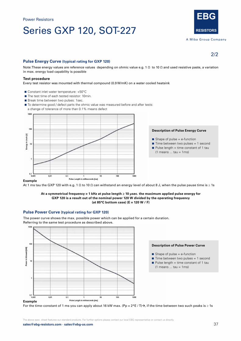
[email protected] · [email protected]
The above spec. sheet features our standard products. For further options please contact our local EBG representative or contact us directly.
Power Resistors
2/2Pulse Energy Curve (typical rating for GXP 120)
Note: These energy values are reference values depending on ohmic value e.g. 1 Ω to 10 Ω and used resistive paste, a variationin max. energy load capability is possible
Pulse Power Curve (typical rating for GXP 120)
The power curve shows the max. possible power which can be applied for a certain duration.Referring to the same test procedure as described above.
Test procedureEvery test resistor was mounted with thermal compound (0.9 W/mK) on a water cooled heatsink
Constant inlet water temperature: +50°C The test time of each tested resistor: 10min. Break time between two pulses: 1sec. To determine good / defect parts the ohmic value was measured before and after tests: a change of tolerance of more than 0.1% means defect
ExampleAt 1 ms tau the GXP 120 with e.g. 1 Ω to 10 Ω can withstand an energy level of about 8 J, when the pulse pause time is ≥ 1s
At a symmetrical frequency > 1 kHz at pulse length ≥ 10 μsec. the maximum applied pulse energy forGXP 120 is a result out of the nominal power 120 W divided by the operating frequency
(at 85°C bottom case) (E = 120 W / F)
ExampleFor the time-constant of 1 ms you can apply about 16 kW max. (Pp = 2*E / τ)à, if the time between two such peaks is ≥ 1s
Description of Pulse Energy Curve
Shape of pulse = e-function Time between two pulses = 1 second Pulse length = time constant of 1 tau (1 means ... tau = 1ms)
Description of Pulse Power Curve
Shape of pulse = e-function Time between two pulses = 1 second Pulse length = time constant of 1 tau (1 means ... tau = 1ms)
Series GXP 120, SOT-227

38 [email protected] · [email protected]
The above spec. sheet features our standard products. For further options please contact our local EBG representative or contact us directly.
Derating (thermal resist.) HPP-150:
2.14 W/K (0.47 K/W) (for conf. 3)
Best results can be reached by using a thermal transfer compound with a heat conductivity of at least 1 W/mK. The flatness of the cooling plate must be better than 0.05 mm overall. Surface roughness should not exceed 6.4 μm.
Resistance value 1 Ω ≤ 1 MΩ (other values on special request)
Resistance tolerance ±1 % to ±10 %
Temperature coefficient ±250 ppm/°C (at +85°C ref. to + 25°C)lower TCR on special request for limited ohmic values
Power rating up to 150 W at 85°C bottom case temperature(see configurations)
Maximum working voltage 500 V(up to 1,000 V DC on special request = "S"-version)
Voltage proof 5,000 V DC, 3,000 V AC
Insulations resistance 10 GΩ min. at 1 kV DC
Insolation voltage between R1 & R2 500 V (1,000 V on special request)
Comparative Tracking Index (CTI) standard > 200 V(> 500 V on special request = "H"-version)
Heat resistance to cooling plate Rth < 0.47 K/W
Capacitance/mass 45 pF (typical), measuring frequency 10 kHz
Working temperatur range -55°C to +155°C
Mounting - torque for base plate (static) 1.3 Nm to 1.5 Nm M5 screws
Weight ~38 g
Technical Specifications
Features multiple resistors in 1 package Easy mounting using already existing infrastructure Non-Inductive design ROHS compliant Materials in accordance with UL 94 V-0 and VDE 0160
EBG Resistors´s HPP series is rated at 150 W mounted to a heat sink. The increased height of the package makes the resistor ideal in applications where creeping distance must meet the VDE 0160 and UL 94 V-0 standards.
Dimensions in mm [inches]
How to make a request HPP-Configuration_Ohmic Value_Tolerance
For example:
HPP-5 2x2R 10% or HPP-6 3x8K 5%
Example for higher working voltage:
HPP-4-S 2x10R 5%
Air distance contact to contact:
Contacts 1 and 2 resp. 3 and 4 - without fast-on-Plug: 9.2 mm - with fast-on-Plug: 8.2 mm
Contacts 1 and 4 resp. 2 and 3 - without fast-on-Plug: 21.9 mm - with fast-on-Plug: 20.9 mm
Contacts 2 resp. 3 and M5 - mounting screw with washer - without fast-on-Plug: 16.3 mm - with fast-on-Plug: 15.9 mm
Contacts 1 resp. 4 and M5 - mounting screw with washer - without fast-on-Plug: 15.5 mm - with fast-on-Plug: 15.0 mm
Contacts 1 and 2 resp. 3 and 4 - without fast-on-Plug: 20.2 mm - with fast-on-Plug: 19.0 mm
Contacts 1 and 4 resp. 2 and 3 - without fast-on-Plug: 27.4 mm - with fast-on-Plug: 25.8 mm
Contacts 2 resp. 3 to base plate - without fast-on-Plug: 20.2 mm - with fast-on-Plug: 19.8 mm
Contacts 1 resp. 4 to base plate - without fast-on-Plug: 19.5 mm - with fast-on-Plug: 18.9 mm
Creeping distance:
Configurations (P / package)
Version 5: ohmic value between contact 2 and 3 = 3mΩ
21
343
R2
R1
3
1
4
2
4
R2
R1
34
1 2
5
R3
R2
34
6
R11 2
150 W
2x60 W
2x60 W
3x33 W
Power Resistors
Series HPP 150150 W Power Resistor according to VDE 0160 und UL 94 V-0
1/2

[email protected] · [email protected]
The above spec. sheet features our standard products. For further options please contact our local EBG representative or contact us directly.
Power Resistors
2/2Pulse Energy Curve (typical rating for HPP 150)
Note: These energy values are reference values → depending on ohmic value e.g. 1 Ω to 10 Ω and used resistive paste, a variationin max. energy load capability is possible
Pulse Power Curve (typical rating for HPP 150)
The power curve shows the max. possible power which can be applied for a certain duration.Referring to the same test procedure as described above.
Test procedureEvery test resistor was mounted with thermal compound (0.9 W/mK) on a water cooled heatsink
Constant inlet water temperature: +50°C The test time of each tested resistor: 10min. Break time between two pulses: 1sec. To determine good / defect parts the ohmic value was measured before and after tests: a change of tolerance of more than 0.1% means defect
ExampleAt 1 ms tau the HPP 150 with e.g. 1 Ω to 10 Ω can withstand an energy level of about 10 J, when the pulse pause time is ≥ 1s
At a symmetrical frequency > 1 kHz at pulse length ≥ 10 μsec. the maximum applied pulse energy forHPP 150 is a result out of the nominal power 150 W divided by the operating frequency
(at 85°C bottom case) (E = 150 W / F)
ExampleFor the time-constant of 1 ms you can apply about 20 kW max. (Pp = 2*E / τ)à, if the time between two such peaks is ≥ 1s
Description of Pulse Energy Curve
Shape of pulse = e-function Time between two pulses = 1 second Pulse length = time constant of 1 tau (1 means ... tau = 1ms)
Description of Pulse Power Curve
Shape of pulse = e-function Time between two pulses = 1 second Pulse length = time constant of 1 tau (1 means ... tau = 1ms)
Series HPP 150
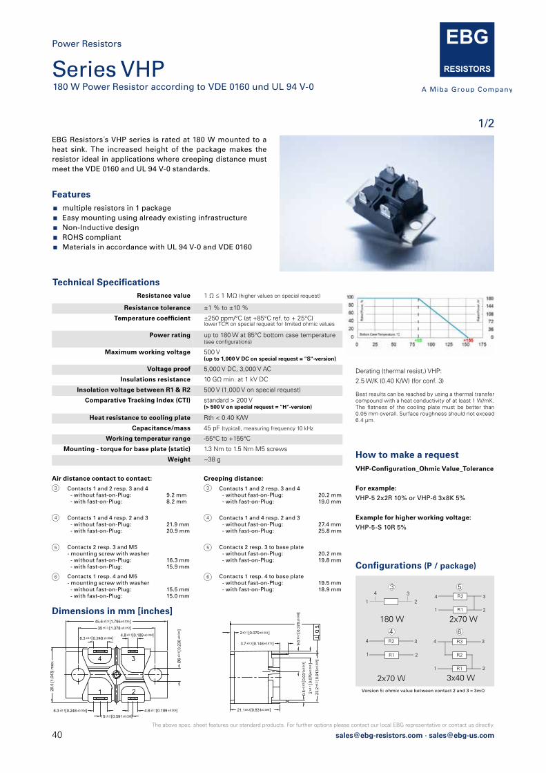
40 [email protected] · [email protected]
The above spec. sheet features our standard products. For further options please contact our local EBG representative or contact us directly.
Power Resistors
Series VHP180 W Power Resistor according to VDE 0160 und UL 94 V-0
1/2EBG Resistors´s VHP series is rated at 180 W mounted to a heat sink. The increased height of the package makes the resistor ideal in applications where creeping distance must meet the VDE 0160 and UL 94 V-0 standards.
Technical Specifications Resistance value 1 Ω ≤ 1 MΩ (higher values on special request)
Resistance tolerance ±1 % to ±10 %
Temperature coefficient ±250 ppm/°C (at +85°C ref. to + 25°C)lower TCR on special request for limited ohmic values
Power rating up to 180 W at 85°C bottom case temperature(see configurations)
Maximum working voltage 500 V(up to 1,000 V DC on special request = "S"-version)
Voltage proof 5,000 V DC, 3,000 V AC
Insulations resistance 10 GΩ min. at 1 kV DC
Insolation voltage between R1 & R2 500 V (1,000 V on special request)
Comparative Tracking Index (CTI) standard > 200 V(> 500 V on special request = "H"-version)
Heat resistance to cooling plate Rth < 0.40 K/W
Capacitance/mass 45 pF (typical), measuring frequency 10 kHz
Working temperatur range -55°C to +155°C
Mounting - torque for base plate (static) 1.3 Nm to 1.5 Nm M5 screws
Weight ~38 g
Dimensions in mm [inches]
Derating (thermal resist.) VHP:
2.5 W/K (0.40 K/W) (for conf. 3)
Best results can be reached by using a thermal transfer compound with a heat conductivity of at least 1 W/mK. The flatness of the cooling plate must be better than 0.05 mm overall. Surface roughness should not exceed 6.4 μm.
Features multiple resistors in 1 package Easy mounting using already existing infrastructure Non-Inductive design ROHS compliant Materials in accordance with UL 94 V-0 and VDE 0160
How to make a request VHP-Configuration_Ohmic Value_Tolerance
For example:
VHP-5 2x2R 10% or VHP-6 3x8K 5%
Example for higher working voltage:
VHP-5-S 10R 5%
Air distance contact to contact:
Contacts 1 and 2 resp. 3 and 4 - without fast-on-Plug: 9.2 mm - with fast-on-Plug: 8.2 mm
Contacts 1 and 4 resp. 2 and 3 - without fast-on-Plug: 21.9 mm - with fast-on-Plug: 20.9 mm
Contacts 2 resp. 3 and M5 - mounting screw with washer - without fast-on-Plug: 16.3 mm - with fast-on-Plug: 15.9 mm
Contacts 1 resp. 4 and M5 - mounting screw with washer - without fast-on-Plug: 15.5 mm - with fast-on-Plug: 15.0 mm
Contacts 1 and 2 resp. 3 and 4 - without fast-on-Plug: 20.2 mm - with fast-on-Plug: 19.0 mm
Contacts 1 and 4 resp. 2 and 3 - without fast-on-Plug: 27.4 mm - with fast-on-Plug: 25.8 mm
Contacts 2 resp. 3 to base plate - without fast-on-Plug: 20.2 mm - with fast-on-Plug: 19.8 mm
Contacts 1 resp. 4 to base plate - without fast-on-Plug: 19.5 mm - with fast-on-Plug: 18.9 mm
Creeping distance:
Configurations (P / package)
Version 5: ohmic value between contact 2 and 3 = 3mΩ
21
343
R2
R1
3
1
4
2
4
R2
R1
34
1 2
5
R3
R2
34
6
R11 2
180 W
2x70 W
2x70 W
3x40 W
3
4
5
6
3
4
5
6
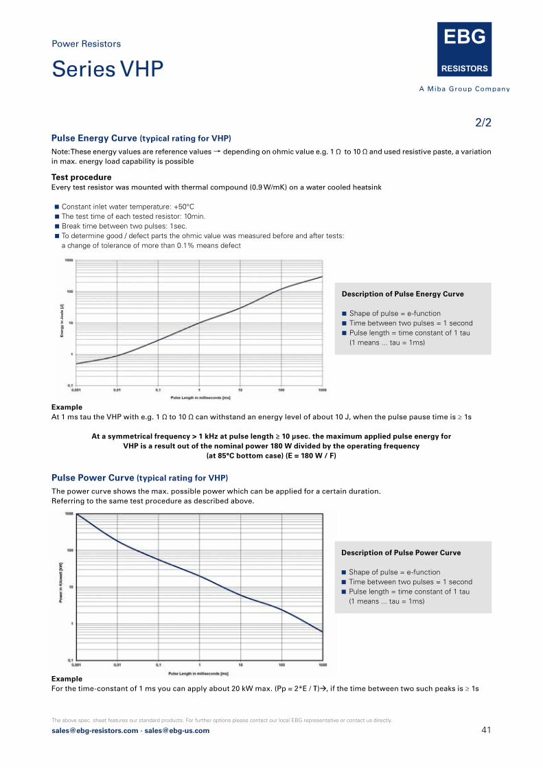
[email protected] · [email protected]
The above spec. sheet features our standard products. For further options please contact our local EBG representative or contact us directly.
Pulse Energy Curve (typical rating for VHP)
Note: These energy values are reference values → depending on ohmic value e.g. 1 Ω to 10 Ω and used resistive paste, a variationin max. energy load capability is possible
Pulse Power Curve (typical rating for VHP)
The power curve shows the max. possible power which can be applied for a certain duration.Referring to the same test procedure as described above.
Test procedureEvery test resistor was mounted with thermal compound (0.9 W/mK) on a water cooled heatsink
Constant inlet water temperature: +50°C The test time of each tested resistor: 10min. Break time between two pulses: 1sec. To determine good / defect parts the ohmic value was measured before and after tests: a change of tolerance of more than 0.1% means defect
ExampleAt 1 ms tau the VHP with e.g. 1 Ω to 10 Ω can withstand an energy level of about 10 J, when the pulse pause time is ≥ 1s
At a symmetrical frequency > 1 kHz at pulse length ≥ 10 μsec. the maximum applied pulse energy forVHP is a result out of the nominal power 180 W divided by the operating frequency
(at 85°C bottom case) (E = 180 W / F)
Description of Pulse Energy Curve
Shape of pulse = e-function Time between two pulses = 1 second Pulse length = time constant of 1 tau (1 means ... tau = 1ms)
Description of Pulse Power Curve
Shape of pulse = e-function Time between two pulses = 1 second Pulse length = time constant of 1 tau (1 means ... tau = 1ms)
ExampleFor the time-constant of 1 ms you can apply about 20 kW max. (Pp = 2*E / τ)à, if the time between two such peaks is ≥ 1s
Power Resistors
2/2
Series VHP
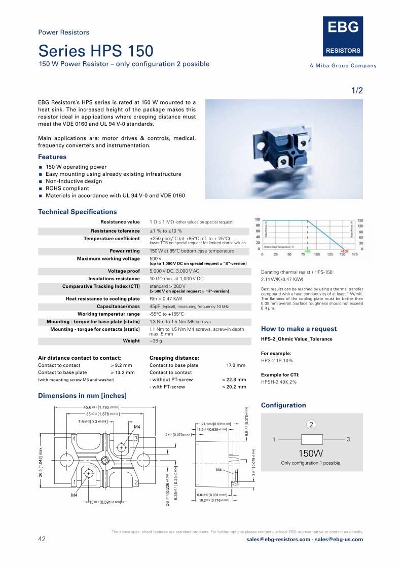
42 [email protected] · [email protected]
The above spec. sheet features our standard products. For further options please contact our local EBG representative or contact us directly.
Power Resistors
Series HPS 150150 W Power Resistor – only configuration 2 possible
1/2EBG Resistors´s HPS series is rated at 150 W mounted to a heat sink. The increased height of the package makes this resistor ideal in applications where creeping distance must meet the VDE 0160 and UL 94 V-0 standards.
Main applications are: motor drives & controls, medical, frequency converters and instrumentation.
Technical Specifications Resistance value 1 Ω ≤ 1 MΩ (other values on special request)
Resistance tolerance ±1 % to ±10 %
Temperature coefficient ±250 ppm/°C (at +85°C ref. to + 25°C)lower TCR on special request for limited ohmic values
Power rating 150 W at 85°C bottom case temperature
Maximum working voltage 500 V(up to 1,000 V DC on special request = "S"-version)
Voltage proof 5,000 V DC, 3,000 V AC
Insulations resistance 10 GΩ min. at 1,000 V DC
Comparative Tracking Index (CTI) standard > 200 V (> 500 V on special request = "H"-version)
Heat resistance to cooling plate Rth < 0.47 K/W
Capacitance/mass 45pF (typical), measuring frequency 10 kHz
Working temperatur range -55°C to +155°C
Mounting - torque for base plate (static) 1.3 Nm to 1.5 Nm M5 screws
Mounting - torque for contacts (static) 1.1 Nm to 1.5 Nm M4 screws, screw-in depth max. 5 mm
Weight ~38 g
Dimensions in mm [inches]
Derating (thermal resist.) HPS-150:
2.14 W/K (0.47 K/W)
Best results can be reached by using a thermal transfer compound with a heat conductivity of at least 1 W/mK. The flatness of the cooling plate must be better than 0.05 mm overall. Surface roughness should not exceed 6.4 μm.
Features 150 W operating power Easy mounting using already existing infrastructure Non-Inductive design ROHS compliant Materials in accordance with UL 94 V-0 and VDE 0160
Air distance contact to contact:Contact to contact > 9.2 mm
Contact to base plate > 13.2 mm
(with mounting screw M5 and washer)
How to make a request HPS-2_Ohmic Value_Tolerance
For example:
HPS-2 1R 10%
Example for CTI:
HPSH-2 40K 2%
26.5
[1.0
43] m
ax.
Ø6
±0.1
0.23
6±0
.004
]
15±0.2 0.591±0.008]
35 ±0.3 1.378 ±0.012]
M4
±0.9 1.795 ±0.035]
M4
7.6 ±0.2 0.3 ±0.008]
45.6
6.35
±0.1
0.25
±0.0
04]
2±0.1 0.079 ±0.004]
21.1±0.2 0.831±0.008]
3±0
.10.
079
±0.0
04]
M4
16.2±0.2 0.638 ±0.008]
0.8±0.03 0.031±0.001]18.2±0.2 0.716±0.008]
Creeping distance: Contact to base plate 17.0 mm
Contact to contact
- without PT-screw > 22.8 mm
- with PT-screw > 20.2 mm
Configuration
150W
31
2
Only conguration 1 possible
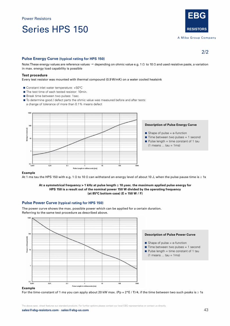
[email protected] · [email protected]
The above spec. sheet features our standard products. For further options please contact our local EBG representative or contact us directly.
Pulse Energy Curve (typical rating for HPS 150)
Note: These energy values are reference values → depending on ohmic value e.g. 1 Ω to 10 Ω and used resistive paste, a variationin max. energy load capability is possible
Pulse Power Curve (typical rating for HPS 150)
The power curve shows the max. possible power which can be applied for a certain duration.Referring to the same test procedure as described above.
Test procedureEvery test resistor was mounted with thermal compound (0.9 W/mK) on a water cooled heatsink
Constant inlet water temperature: +50°C The test time of each tested resistor: 10min. Break time between two pulses: 1sec. To determine good / defect parts the ohmic value was measured before and after tests: a change of tolerance of more than 0.1% means defect
ExampleAt 1 ms tau the HPS 150 with e.g. 1 Ω to 10 Ω can withstand an energy level of about 10 J, when the pulse pause time is ≥ 1s
At a symmetrical frequency > 1 kHz at pulse length ≥ 10 μsec. the maximum applied pulse energy forHPS 150 is a result out of the nominal power 150 W divided by the operating frequency
(at 85°C bottom case) (E = 150 W / F)
Description of Pulse Energy Curve
Shape of pulse = e-function Time between two pulses = 1 second Pulse length = time constant of 1 tau (1 means ... tau = 1ms)
Description of Pulse Power Curve
Shape of pulse = e-function Time between two pulses = 1 second Pulse length = time constant of 1 tau (1 means ... tau = 1ms)
ExampleFor the time-constant of 1 ms you can apply about 20 kW max. (Pp = 2*E / τ)à, if the time between two such peaks is ≥ 1s
2/2
Power Resistors
Series HPS 150
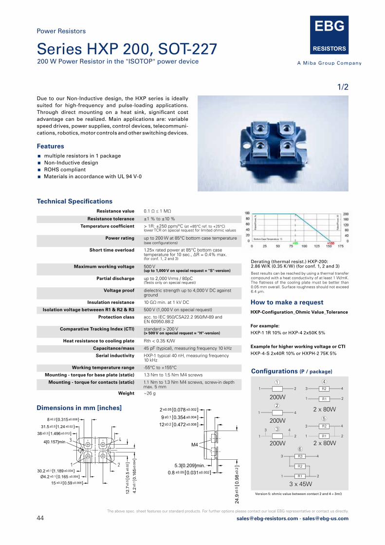
44 [email protected] · [email protected]
The above spec. sheet features our standard products. For further options please contact our local EBG representative or contact us directly.
Due to our Non-Inductive design, the HXP series is ideallysuited for high-frequency and pulse-loading applications.Through direct mounting on a heat sink, significant costadvantage can be realized. Main applications are: variable speed drives, power supplies, control devices, telecommuni-cations, robotics, motor controls and other switching devices.
Features multiple resistors in 1 package Non-Inductive design ROHS compliant Materials in accordance with UL 94 V-0
How to make a request HXP-Configuration_Ohmic Value_Tolerance
For example:
HXP-1 1R 10% or HXP-4 2x50K 5%
Example for higher working voltage or CTI
HXP-4-S 2x40R 10% or HXPH-2 75K 5%
Dimensions in mm [inches]
Technical Specifications Resistance value 0.1 Ω ≤ 1 MΩ
Resistance tolerance ±1 % to ±10 %
Temperature coefficient > 1R: ±250 ppm/°C (at +85°C ref. to +25°C)lower TCR on special request for limited ohmic values
Power rating up to 200 W at 85°C bottom case temperature (see configurations)
Short time overload 1.25x rated power at 85°C bottom casetemperature for 10 sec., ΔR = 0.4% max.(for conf. 1, 2 and 3)
Maximum working voltage 500 V(up to 1,000 V on special request = "S"-version)
Partial discharge up to 2,000 Vrms / 80pC(Tests only on special request)
Voltage proof dielectric strength up to 4,000 V DC againstground
Insulation resistance 10 GΩ min. at 1 kV DC
Isolation voltage betweeen R1 & R2 & R3 500 V (1,000 V on special request)
Protection class acc. to IEC 950/CSA22.2 950/M-89 and EN 60950.88:2
Comparative Tracking Index (CTI) standard > 200 V (> 500 V on special request = "H"-version)
Heat resistance to cooling plate Rth < 0.35 K/W
Capacitance/mass 45 pF (typical), measuring frequency 10 kHz
Serial inductivity HXP-1 typical 40 nH, measuring frequency 10 kHz
Working temperature range -55°C to +155°C
Mounting - torque for base plate (static) 1.3 Nm to 1.5 Nm M4 screws
Mounting - torque for contacts (static) 1.1 Nm to 1.3 Nm M4 screws, screw-in depth max. 5 mm
Weight ~26 g
Derating (thermal resist.) HXP-200:2.86 W/K (0.35 K/W) (for conf. 1, 2 and 3)
Best results can be reached by using a thermal transfer compound with a heat conductivity of at least 1 W/mK. The flatness of the cooling plate must be better than 0.05 mm overall. Surface roughness should not exceed 6.4 μm.
2 ±0.05 0.078 ±0.002]9 ±0.1 0.354±0.004]
12±0.2 0.472±0.008]
5.3[0.209]min.0.8 ±0.05 0.031±0.002]
M4
24.9
±0.5
0.98
±0.2
]
Configurations (P / package)
Version 5: ohmic value between contact 2 and 4 = 3mΩ
200W
200W
200W
2 x 80W
2 x 80W
21
1
4
2
R2
R1
R2
R1
1
3 43 4
1 2
3
1
4
2
1
2
3
4
5
R3
R2
43
6
R11 2
3 x 45W
Power Resistors
Series HXP 200, SOT-227200 W Power Resistor in the "ISOTOP" power device
1/2
8 ±0.2 0.315±0.008]
31.5 ±0.5 1.24 ±0.02 ]
38±0.3 1.496±0.012]
30.2 ±0.1 1.189 ±0.004]
15 ±0.2 0.59±0.008]
4.2
±0.1
0.16
5±0.
004 ]
12.7
±0.5
0.5
±0.0
2]
4[0.157]min
Ø4.2 ±0.1 0.165 ±0.004]

[email protected] · [email protected]
The above spec. sheet features our standard products. For further options please contact our local EBG representative or contact us directly.
2/2
Power Resistors
Pulse Energy Curve (typical rating for HXP 200)
Note: These energy values are reference values → depending on ohmic value e.g. 1 Ω to 10 Ω and used resistive paste, a variationin max. energy load capability is possible
Pulse Power Curve (typical rating for HXP 200)
The power curve shows the max. possible power which can be applied for a certain duration.Referring to the same test procedure as described above.
Test procedureEvery test resistor was mounted with thermal compound (0.9 W/mK) on a water cooled heatsink
Constant inlet water temperature: +50°C The test time of each tested resistor: 10min. Break time between two pulses: 1sec. To determine good / defect parts the ohmic value was measured before and after tests: a change of tolerance of more than 0.1% means defect
ExampleAt 1 ms tau the HXP 200 with e.g. 1 Ω to 10 Ω can withstand an energy level of about 10 J, when the pulse pause time is ≥ 1s
At a symmetrical frequency > 1 kHz at pulse length ≥ 10 μsec. the maximum applied pulse energy forHXP 200 is a result out of the nominal power 200 W divided by the operating frequency
(at 85°C bottom case) (E = 200 W / F)
ExampleFor the time-constant of 1 ms you can apply about 20 kW max. (Pp = 2*E / τ)à, if the time between two such peaks is ≥ 1s
Description of Pulse Energy Curve
Shape of pulse = e-function Time between two pulses = 1 second Pulse length = time constant of 1 tau (1 means ... tau = 1ms)
Description of Pulse Power Curve
Shape of pulse = e-function Time between two pulses = 1 second Pulse length = time constant of 1 tau (1 means ... tau = 1ms)
Series HXP 200, SOT-227

46 [email protected] · [email protected]
The above spec. sheet features our standard products. For further options please contact our local EBG representative or contact us directly.
Power Resistors
Series AXM100 W Low Ohm Pulse Power Resistor - only configuration 1 possible
1/1
How to make a request AXM-1 B_Ohmic Value_Tolerance
For example:
AXM-1 B 0R1 10%
This model is designed for high pulse withstanding capabilities. The AXM series is usually used in areas where stringent pulse withstanding requirements are common such as welding equipment, variable speed drives and motor control and other switching devices.
Technical Specifications Resistance value 0.05 Ω ≤ 0.5 Ω
Resistance tolerance ±10 % standard± 5 % on special request f. limited ohmic values
Temperature coefficient typical ±500 ppm/°C (at +85°C ref. to + 25°C)
Power rating 100 W at 85°C bottom case temperature
Maximum working voltage up to 500 V (depending on pulse load scenario)
Electric strength voltage 3 kV DC (1.5 kV AC, higher values on special request)between terminal and case
Working temperatur range -55°C to +155°C
Standard wire length L = 10 mm(other lengths available on special request)
Mounting - torque 1.0 Nm to 1.2 Nm
Weight ~18 g
Dimensions in mm [inches]
Best results can be reached by using a thermal transfer compound with a heat conductivity of at least 1 W/mK. The flatness of the cooling plate must be better than 0.05 mm overall. Surface roughness should not exceed 6.4 μm.
Features 100 W operating power Non-Inductive design ROHS compliant Materials in accordance with UL 94V-0
Please let us know your exact pulse parameters to offer you the best option / design details.
Suggested Mounting Procedure:
1.) Position component and press down by hand
2.) Fix both mounting screws (M4) with 0.1 to 0.2 Nm torque
3.) Apply final torque to mounting screws of 1.0 to 1.2 Nm
16.8 ±0.5 0.66 ±0.02 ]
45 ±0.2 1.77 ±0.008 ]
22.5
±0.5
0.88
6±0
.02]
29.9±0.2 1.177±0.008]
20±1 0.787±0.04]
10.25±0.25 0.403±0.01]
6 ±0.2 0.236±0.008]4.05±0.15 0.159 ±0.006]
Configuration
100W
21
1
Only conguration 1 possible
Boreholes distance from min. 30.0 mm to max. 37.0 mm
[email protected] · [email protected]
The above spec. sheet features our standard products. For further options please contact our local EBG representative or contact us directly.
Ultra-High-Power ResistorsUXP-350UXP-600UXP-800UPT-400UPT-600UPT-800ULX-600ULX-800UXM-400
47
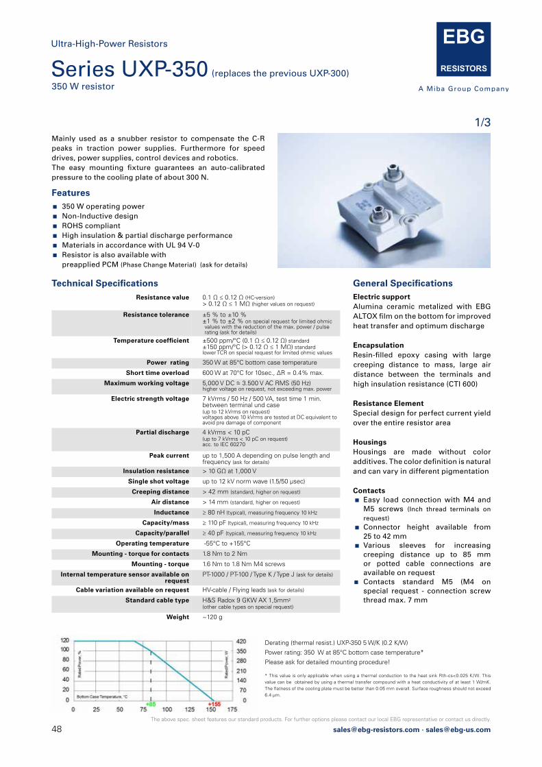
48 [email protected] · [email protected]
The above spec. sheet features our standard products. For further options please contact our local EBG representative or contact us directly.
Series UXP-350 (replaces the previous UXP-300)350 W resistor
1/3Mainly used as a snubber resistor to compensate the C-R peaks in traction power supplies. Furthermore for speed drives, power supplies, control devices and robotics.The easy mounting fixture guarantees an auto-calibrated pressure to the cooling plate of about 300 N.
Features 350 W operating power Non-Inductive design ROHS compliant High insulation & partial discharge performance Materials in accordance with UL 94 V-0 Resistor is also available with
preapplied PCM (Phase Change Material) (ask for details)
Resistance value 0.1 Ω ≤ 0.12 Ω (HC-version)> 0.12 Ω ≤ 1 MΩ (higher values on request)
Resistance tolerance ±5 % to ±10 %±1 % to ±2 % on special request for limited ohmic values with the reduction of the max. power / pulse rating (ask for details)
Temperature coefficient ±500 ppm/°C (0.1 Ω ≤ 0.12 Ω) standard±150 ppm/°C (> 0.12 Ω ≤ 1 MΩ) standardlower TCR on special request for limited ohmic values
Power rating 350 W at 85°C bottom case temperature
Short time overload 600 W at 70°C for 10sec., ΔR = 0.4% max.
Maximum working voltage 5,000 V DC = 3.500 V AC RMS (50 Hz)higher voltage on request, not exceeding max. power
Electric strength voltage 7 kVrms / 50 Hz / 500 VA, test time 1 min.between terminal und case(up to 12 kVrms on request)voltages above 10 kVrms are tested at DC equivalent to avoid pre damage of component
Partial discharge 4 kVrms < 10 pC(up to 7 kVrms < 10 pC on request)acc. to IEC 60270
Peak current up to 1,500 A depending on pulse length andfrequency (ask for details)
Insulation resistance > 10 GΩ at 1,000 V
Single shot voltage up to 12 kV norm wave (1.5/50 μsec)
Creeping distance > 42 mm (standard, higher on request)
Air distance > 14 mm (standard, higher on request)
Inductance ≥ 80 nH (typical), measuring frequency 10 kHz
Capacity/mass ≥ 110 pF (typical), measuring frequency 10 kHz
Capacity/parallel ≥ 40 pF (typical), measuring frequency 10 kHz
Operating temperature -55°C to +155°C
Mounting - torque for contacts 1.8 Nm to 2 Nm
Mounting - torque 1.6 Nm to 1.8 Nm M4 screws
Internal temperature sensor available on request
PT-1000 / PT-100 / Type K / Type J (ask for details)
Cable variation available on request HV-cable / Flying leads (ask for details)
Standard cable type H&S Radox 9 GKW AX 1,5mm2(other cable types on special request)
Weight ~120 g
Technical Specifications General Specifications Electric supportAlumina ceramic metalized with EBG ALTOX film on the bottom for improved heat transfer and optimum discharge
EncapsulationResin-filled epoxy casing with large creeping distance to mass, large air distance between the terminals and high insulation resistance (CTI 600)
Resistance ElementSpecial design for perfect current yield over the entire resistor area
Housings Housings are made without color additives. The color definition is natural and can vary in different pigmentation
Contacts Easy load connection with M4 and
M5 screws (Inch thread terminals on request)
Connector height available from 25 to 42 mm
Various sleeves for increasing creeping distance up to 85 mm or potted cable connections are available on request
Contacts standard M5 (M4 on special request - connection screw thread max. 7 mm
Derating (thermal resist.) UXP-350 5 W/K (0.2 K/W)
Power rating: 350 W at 85°C bottom case temperature*
Please ask for detailed mounting procedure!
* This value is only applicable when using a thermal conduction to the heat sink Rth-cs<0.025 K/W. This value can be obtained by using a thermal transfer compound with a heat conductivity of at least 1 W/mK. The flatness of the cooling plate must be better than 0.05 mm overall. Surface roughness should not exceed 6.4 μm.
Ultra-High-Power Resistors
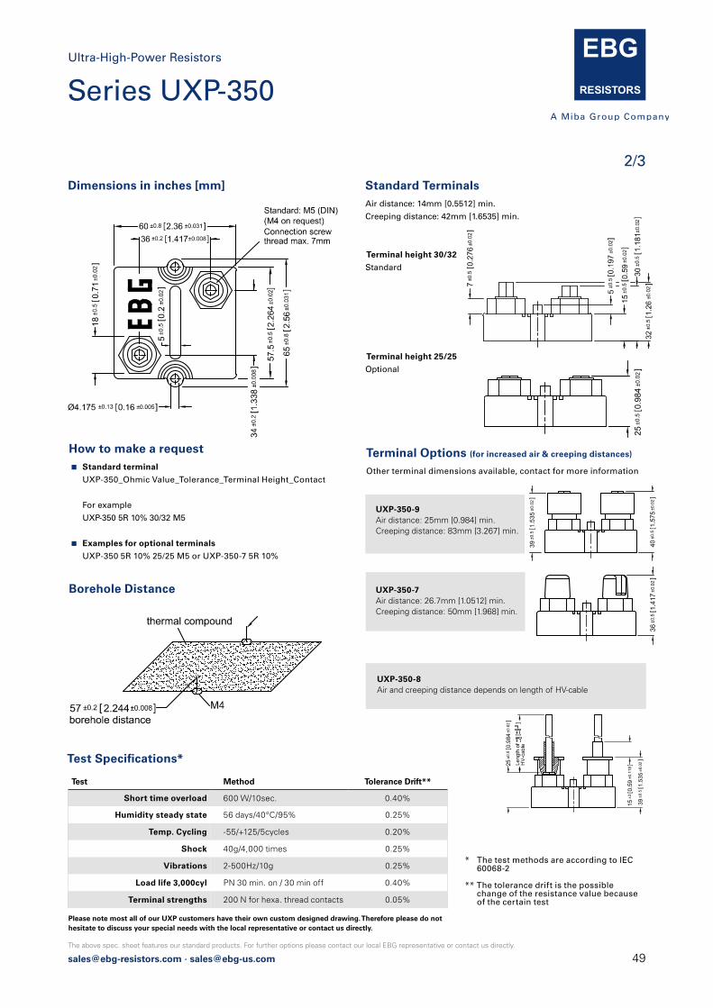
[email protected] · [email protected]
The above spec. sheet features our standard products. For further options please contact our local EBG representative or contact us directly.
2/3
Dimensions in inches [mm] Standard TerminalsAir distance: 14mm [0.5512] min.
Creeping distance: 42mm [1.6535] min.
Terminal height 30/32
Standard
Terminal height 25/25
Optional
* The test methods are according to IEC 60068-2
** The tolerance drift is the possible change of the resistance value because
of the certain test
25±0
.50.
984
±0.02]
How to make a request Standard terminal
UXP-350_Ohmic Value_Tolerance_Terminal Height_Contact
For example
UXP-350 5R 10% 30/32 M5
Examples for optional terminals
UXP-350 5R 10% 25/25 M5 or UXP-350-7 5R 10%
39±0
.51.
535
±0.02]
39±0
.51.
535
±0.02]
Terminal Options (for increased air & creeping distances)
Other terminal dimensions available, contact for more information
UXP-350-9Air distance: 25mm [0.984] min.Creeping distance: 83mm [3.267] min.
UXP-350-7Air distance: 26.7mm [1.0512] min.Creeping distance: 50mm [1.968] min.
UXP-350-8Air and creeping distance depends on length of HV-cable
39±0
.51.
535
±0.02]
Test Method Tolerance Drift**
Short time overload 600 W/10sec. 0.40%
Humidity steady state 56 days/40°C/95% 0.25%
Temp. Cycling -55/+125/5cycles 0.20%
Shock 40g/4,000 times 0.25%
Vibrations 2-500Hz/10g 0.25%
Load life 3,000cyl PN 30 min. on / 30 min off 0.40%
Terminal strengths 200 N for hexa. thread contacts 0.05%
Test Specifications*
Borehole Distance
Ultra-High-Power Resistors
Series UXP-350
Please note most all of our UXP customers have their own custom designed drawing. Therefore please do not hesitate to discuss your special needs with the local representative or contact us directly.
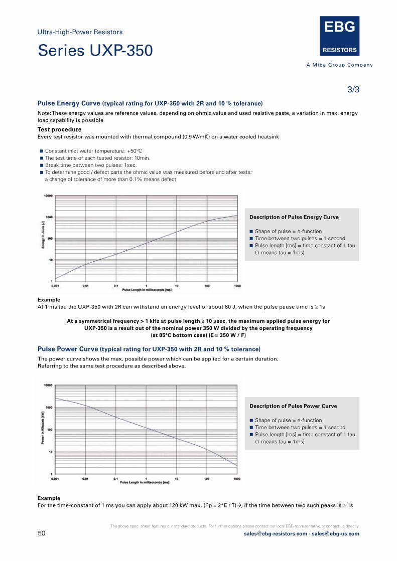
50 [email protected] · [email protected]
The above spec. sheet features our standard products. For further options please contact our local EBG representative or contact us directly.
3/3
Pulse Energy Curve (typical rating for UXP-350 with 2R and 10 % tolerance)
Note: These energy values are reference values, depending on ohmic value and used resistive paste, a variation in max. energyload capability is possible
Pulse Power Curve (typical rating for UXP-350 with 2R and 10 % tolerance)
The power curve shows the max. possible power which can be applied for a certain duration.Referring to the same test procedure as described above.
Test procedureEvery test resistor was mounted with thermal compound (0.9 W/mK) on a water cooled heatsink
Constant inlet water temperature: +50°C The test time of each tested resistor: 10min. Break time between two pulses: 1sec. To determine good / defect parts the ohmic value was measured before and after tests: a change of tolerance of more than 0.1% means defect
ExampleAt 1 ms tau the UXP-350 with 2R can withstand an energy level of about 60 J, when the pulse pause time is ≥ 1s
At a symmetrical frequency > 1 kHz at pulse length ≥ 10 μsec. the maximum applied pulse energy forUXP-350 is a result out of the nominal power 350 W divided by the operating frequency
(at 85°C bottom case) (E = 350 W / F)
ExampleFor the time-constant of 1 ms you can apply about 120 kW max. (Pp = 2*E / τ)à, if the time between two such peaks is ≥ 1s
Description of Pulse Energy Curve
Shape of pulse = e-function Time between two pulses = 1 second Pulse length [ms] = time constant of 1 tau (1 means tau = 1ms)
Description of Pulse Power Curve
Shape of pulse = e-function Time between two pulses = 1 second Pulse length [ms] = time constant of 1 tau (1 means tau = 1ms)
Ultra-High-Power Resistors
Series UXP-350
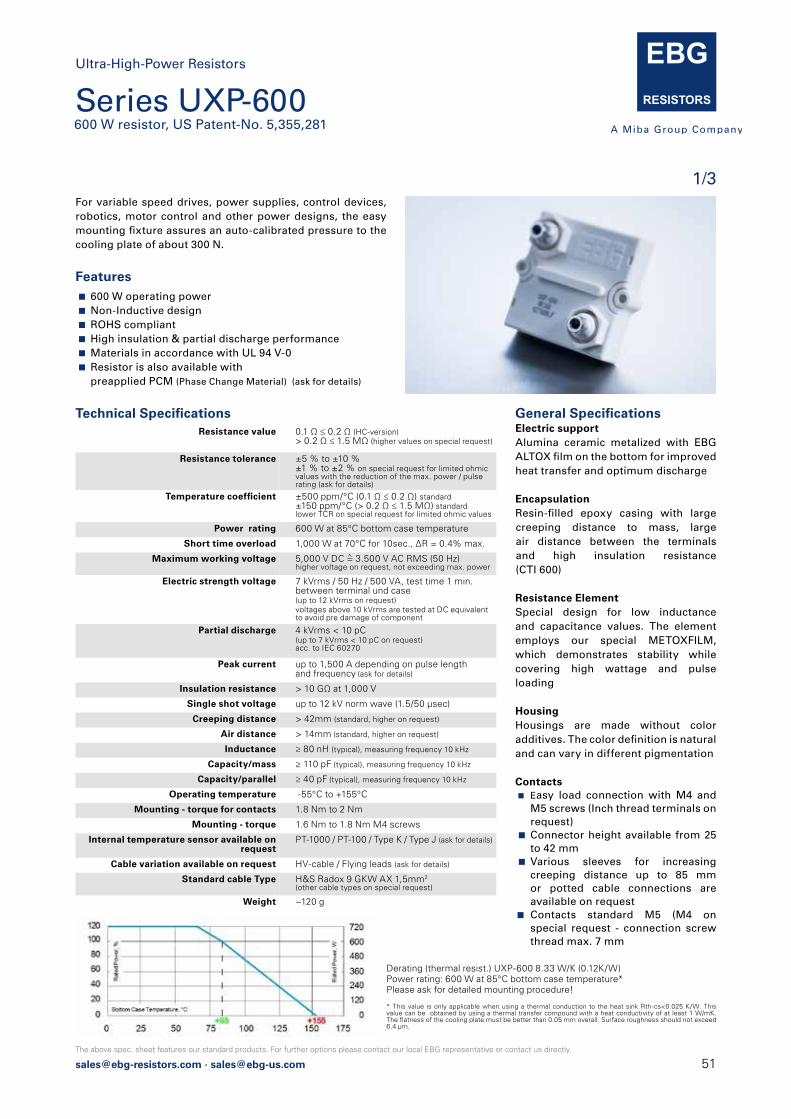
[email protected] · [email protected]
The above spec. sheet features our standard products. For further options please contact our local EBG representative or contact us directly.
1/3
Series UXP-600600 W resistor, US Patent-No. 5,355,281
Derating (thermal resist.) UXP-600 8.33 W/K (0.12K/W)Power rating: 600 W at 85°C bottom case temperature*Please ask for detailed mounting procedure!
* This value is only applicable when using a thermal conduction to the heat sink Rth-cs<0.025 K/W. This value can be obtained by using a thermal transfer compound with a heat conductivity of at least 1 W/mK. The flatness of the cooling plate must be better than 0.05 mm overall. Surface roughness should not exceed 6.4 μm.
For variable speed drives, power supplies, control devices, robotics, motor control and other power designs, the easy mounting fixture assures an auto-calibrated pressure to the cooling plate of about 300 N.
General Specifications Electric supportAlumina ceramic metalized with EBG ALTOX film on the bottom for improved heat transfer and optimum discharge
EncapsulationResin-filled epoxy casing with large creeping distance to mass, large air distance between the terminals and high insulation resistance (CTI 600)
Resistance ElementSpecial design for low inductance and capacitance values. The element employs our special METOXFILM, which demonstrates stability while covering high wattage and pulse loading
HousingHousings are made without color additives. The color definition is natural and can vary in different pigmentation
Contacts Easy load connection with M4 and
M5 screws (Inch thread terminals on request)
Connector height available from 25 to 42 mm
Various sleeves for increasing creeping distance up to 85 mm or potted cable connections are available on request
Contacts standard M5 (M4 on special request - connection screw thread max. 7 mm
Technical Specifications Resistance value 0.1 Ω ≤ 0.2 Ω (HC-version)
> 0.2 Ω ≤ 1.5 MΩ (higher values on special request)
Resistance tolerance ±5 % to ±10 %±1 % to ±2 % on special request for limited ohmic values with the reduction of the max. power / pulse rating (ask for details)
Temperature coefficient ±500 ppm/°C (0.1 Ω ≤ 0.2 Ω) standard±150 ppm/°C (> 0.2 Ω ≤ 1.5 MΩ) standardlower TCR on special request for limited ohmic values
Power rating 600 W at 85°C bottom case temperature
Short time overload 1,000 W at 70°C for 10sec., ΔR = 0.4% max.
Maximum working voltage 5,000 V DC = 3.500 V AC RMS (50 Hz)higher voltage on request, not exceeding max. power
Electric strength voltage 7 kVrms / 50 Hz / 500 VA, test time 1 min. between terminal und case (up to 12 kVrms on request)voltages above 10 kVrms are tested at DC equivalent to avoid pre damage of component
Partial discharge 4 kVrms < 10 pC(up to 7 kVrms < 10 pC on request)acc. to IEC 60270
Peak current up to 1,500 A depending on pulse lengthand frequency (ask for details)
Insulation resistance > 10 GΩ at 1,000 V
Single shot voltage up to 12 kV norm wave (1.5/50 μsec)
Creeping distance > 42mm (standard, higher on request)
Air distance > 14mm (standard, higher on request)
Inductance ≥ 80 nH (typical), measuring frequency 10 kHz
Capacity/mass ≥ 110 pF (typical), measuring frequency 10 kHz
Capacity/parallel ≥ 40 pF (typical), measuring frequency 10 kHz
Operating temperature -55°C to +155°C
Mounting - torque for contacts 1.8 Nm to 2 Nm
Mounting - torque 1.6 Nm to 1.8 Nm M4 screws
Internal temperature sensor available on request
PT-1000 / PT-100 / Type K / Type J (ask for details)
Cable variation available on request HV-cable / Flying leads (ask for details)
Standard cable Type H&S Radox 9 GKW AX 1,5mm2 (other cable types on special request)
Weight ~120 g
Features 600 W operating power Non-Inductive design ROHS compliant High insulation & partial discharge performance Materials in accordance with UL 94 V-0 Resistor is also available with
preapplied PCM (Phase Change Material) (ask for details)
Ultra-High-Power Resistors

52 [email protected] · [email protected]
The above spec. sheet features our standard products. For further options please contact our local EBG representative or contact us directly.
2/3
Dimensions in mm [inches] Standard TerminalsAir distance: 14mm [0.5512] min.
Creeping distance: 42mm [1.6535] min.
Terminal height 30/32Standard
Terminal height 25/25Optional
Test Method Tolerance Drift**
Short time overload 1,000 W/10sec. 0.40%
Humidity steady state 56 days/40°C/95% 0.25%
Temp. Cycling -55/+125/5cycles 0.20%
Shock 40g/4,000 times 0.25%
Vibrations 2-500Hz/10g 0.25%
Load life 3,000cyl PN 30 min. on / 30 min off 0.40%
Terminal strengths 200 N for hexa. thread contacts 0.05%
Test Specifications*
Borehole Distance
How to make a request Standard terminal
UXP-600_Ohmic Value_Tolerance_Terminal Height_Contact
For example
UXP-600 5R 10% 30/32 M5
Examples for optional terminals UXP-600 5R 10% 25/25 M5 or UXP-600-7 5R 10%
25±0
.50.
984±
0.02
]
Terminal Options (for increased air & creeping distances)
Other terminal dimensions available, contact for more information
UXP-600-9Air distance: 25mm [0.984] min.Creeping distance: 83mm [3.267] min.
UXP-600-7Air distance: 26.7mm [1.0512] min.Creeping distance: 50mm [1.968] min.
UXP-600-8Air and creeping distance depends on length of HV-cable
39±0
.51.
535
±0.02]
39±0
.51.
535
±0.02]
* The test methods are according to IEC 60068-2
** The tolerance drift is the possible change of the resistance value because
of the certain test
39±0
.51.
535
±0.0
2]
39±0
.51.
535
±0.0
2]
39±0
.51.
535
±0.0
2]
Ultra-High-Power Resistors
Please note most all of our UXP customers have their own custom designed drawing. Therefore please do not hesitate to discuss your special needs with the local representative or contact us directly.
Series UXP-600

[email protected] · [email protected]
The above spec. sheet features our standard products. For further options please contact our local EBG representative or contact us directly.
3/3Pulse Energy Curve (typical rating for UXP-600 with 10R and 10 % tolerance)
Note: These energy values are reference values, depending on ohmic value and used resistive paste, a variation in max. energy load capability is possible
Pulse Power Curve (typical rating for UXP-600 with 10R and 10 % tolerance)
The power curve shows the max. possible power which can be applied for a certain duration.Referring to the same test procedure as described above.
Test procedureEvery test resistor was mounted with thermal compound (0.9 W/mK) on a water cooled heatsink
Constant inlet water temperature: +50°C The test time of each tested resistor: 10min. Break time between two pulses: 1sec. To determine good / defect parts the ohmic value was measured before and after tests: a change of tolerance of more than 0.1% means defect
Description of Pulse Energy Curve
Shape of pulse = e-function Time between two pulses = 1 second Pulse length [ms] = time constant of 1 tau (1 means tau = 1ms)
Description of Pulse Power Curve
Shape of pulse = e-function Time between two pulses = 1 second Pulse length [ms] = time constant of 1 tau (1 means tau = 1ms)
1
10
100
1000
10000
0,001 0,01 0,1 1 10 100
Ener
gy in
Jou
le [J
]
Pulse Length in milliseconds [ms] 1000
1
10
100
1000
10000
0,001 0,01 0,1 1 10 100
Pow
er in
Kilo
wat
t [kW
]
Pulse Length in milliseconds [ms] 1000
ExampleAt 1 ms tau the UXP-600 with 10R can withstand an energy level of about 60 J, when the pulse pause time is ≥ 1s
At a symmetrical frequency > 1 kHz at pulse length ≥ 10 μsec. the maximum applied pulse energy forUXP-600 is a result out of the nominal power 600 W divided by the operating frequency
(at 85°C bottom case) (E = 600 W / F)
ExampleFor the time-constant of 1 ms you can apply about 120 kW max. (Pp = 2*E / τ)à, if the time between two such peaks is ≥ 1s
Ultra-High-Power Resistors
Series UXP-600
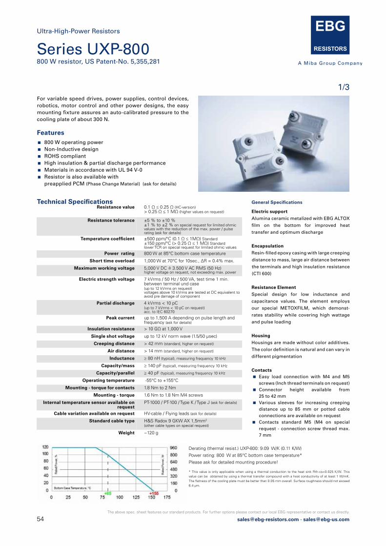
54 [email protected] · [email protected]
The above spec. sheet features our standard products. For further options please contact our local EBG representative or contact us directly.
Series UXP-800800 W resistor, US Patent-No. 5,355,281
1/3For variable speed drives, power supplies, control devices, robotics, motor control and other power designs, the easy mounting fixture assures an auto-calibrated pressure to the cooling plate of about 300 N.
Features 800 W operating power Non-Inductive design ROHS compliant High insulation & partial discharge performance Materials in accordance with UL 94 V-0 Resistor is also available with
preapplied PCM (Phase Change Material) (ask for details)
Technical Specifications Resistance value 0.1 Ω ≤ 0.25 Ω (HC-version)
> 0.25 Ω ≤ 1 MΩ (higher values on request)
Resistance tolerance ±5 % to ±10 %±1 % to ±2 % on special request for limited ohmicvalues with the reduction of the max. power / pulse rating (ask for details)
Temperature coefficient ±500 ppm/°C (0.1 Ω ≤ 1MΩ) Standard±150 ppm/°C (> 0.25 Ω ≤ 1 MΩ) Standardlower TCR on special request for limited ohmic values
Power rating 800 W at 85°C bottom case temperature
Short time overload 1,000 W at 70°C for 10sec., ΔR = 0.4% max.
Maximum working voltage 5,000 V DC = 3.500 V AC RMS (50 Hz)higher voltage on request, not exceeding max. power
Electric strength voltage 7 kVrms / 50 Hz / 500 VA, test time 1 min.between terminal und case (up to 12 kVrms on request)voltages above 10 kVrms are tested at DC equivalent to avoid pre damage of component
Partial discharge 4 kVrms < 10 pC(up to 7 kVrms < 10 pC on request)acc. to IEC 60270
Peak current up to 1,500 A depending on pulse length andfrequency (ask for details)
Insulation resistance > 10 GΩ at 1,000 V
Single shot voltage up to 12 kV norm wave (1.5/50 μsec)
Creeping distance > 42 mm (standard, higher on request)
Air distance > 14 mm (standard, higher on request)
Inductance ≥ 80 nH (typical), measuring frequency 10 kHz
Capacity/mass ≥ 140 pF (typical), measuring frequency 10 kHz
Capacity/parallel ≥ 40 pF (typical), measuring frequency 10 kHz
Operating temperature -55°C to +155°C
Mounting - torque for contacts 1.8 Nm to 2 Nm
Mounting - torque 1.6 Nm to 1.8 Nm M4 screws
Internal temperature sensor available on request
PT-1000 / PT-100 / Type K / Type J (ask for details)
Cable variation available on request HV-cable / Flying leads (ask for details)
Standard cable type H&S Radox 9 GKW AX 1,5mm2
(other cable types on special request)
Weight ~120 g
General Specifications
Electric support
Alumina ceramic metalized with EBG ALTOX
film on the bottom for improved heat
transfer and optimum discharge
Encapsulation
Resin-filled epoxy casing with large creeping
distance to mass, large air distance between
the terminals and high insulation resistance
(CTI 600)
Resistance Element
Special design for low inductance and
capacitance values. The element employs
our special METOXFILM, which demonst-
rates stability while covering high wattage
and pulse loading
Housing
Housings are made without color additives.
The color definition is natural and can vary in
different pigmentation
Contacts Easy load connection with M4 and M5
screws (Inch thread terminals on request) Connector height available from
25 to 42 mm Various sleeves for increasing creeping
distance up to 85 mm or potted cable connections are available on request
Contacts standard M5 (M4 on special request - connection screw thread max. 7 mm
Derating (thermal resist.) UXP-800: 9.09 W/K (0.11 K/W)
Power rating: 800 W at 85°C bottom case temperature*
Please ask for detailed mounting procedure!
* This value is only applicable when using a thermal conduction to the heat sink Rth-cs<0.025 K/W. This value can be obtained by using a thermal transfer compound with a heat conductivity of at least 1 W/mK. The flatness of the cooling plate must be better than 0.05 mm overall. Surface roughness should not exceed 6.4 μm.
Ultra-High-Power Resistors
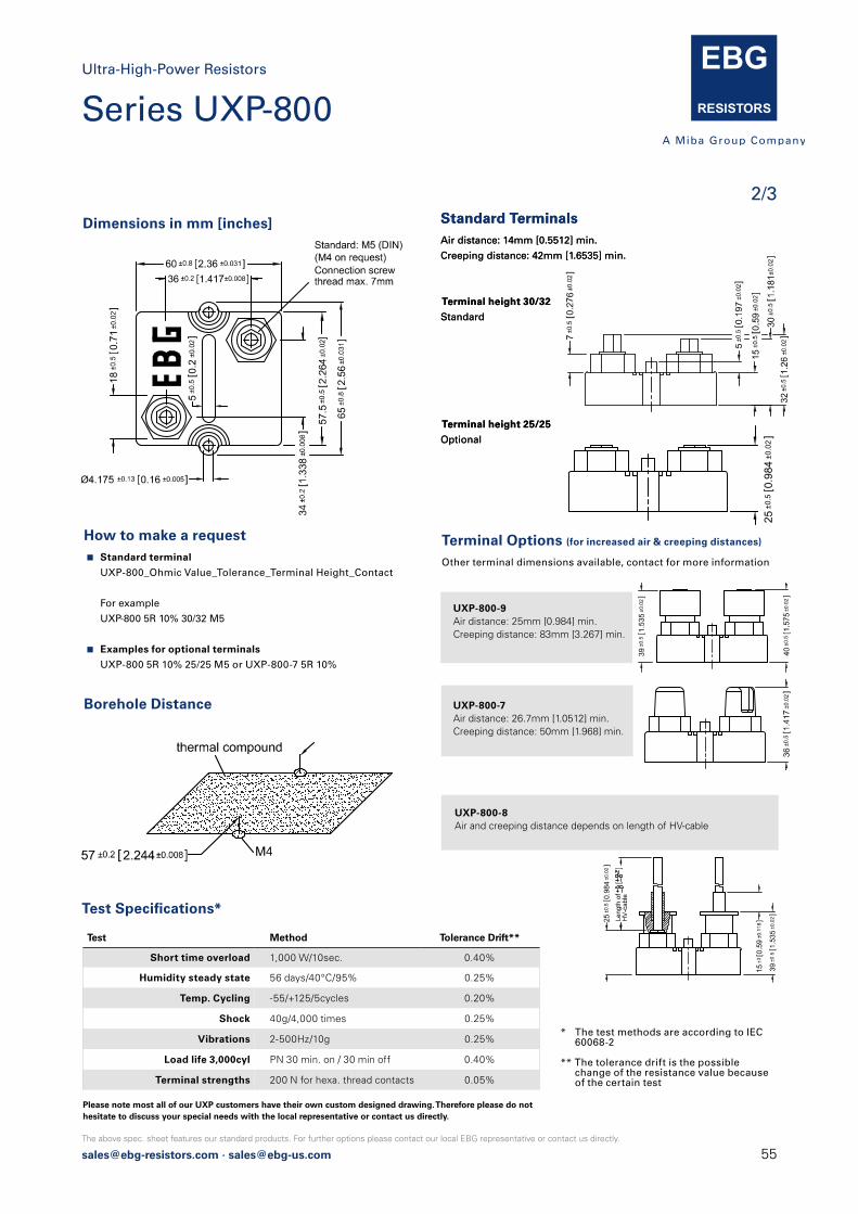
[email protected] · [email protected]
The above spec. sheet features our standard products. For further options please contact our local EBG representative or contact us directly.
2/3
Dimensions in mm [inches] Standard TerminalsAir distance: 14mm [0.5512] min.
Creeping distance: 42mm [1.6535] min.
Terminal height 30/32
Standard
Terminal height 25/25
Optional
How to make a request Standard terminal
UXP-800_Ohmic Value_Tolerance_Terminal Height_Contact
For example
UXP-800 5R 10% 30/32 M5
Examples for optional terminals
UXP-800 5R 10% 25/25 M5 or UXP-800-7 5R 10%
Test Method Tolerance Drift**
Short time overload 1,000 W/10sec. 0.40%
Humidity steady state 56 days/40°C/95% 0.25%
Temp. Cycling -55/+125/5cycles 0.20%
Shock 40g/4,000 times 0.25%
Vibrations 2-500Hz/10g 0.25%
Load life 3,000cyl PN 30 min. on / 30 min off 0.40%
Terminal strengths 200 N for hexa. thread contacts 0.05%
Test Specifications*
Standard TerminalsAir distance: 14mm [0.5512] min.
Creeping distance: 42mm [1.6535] min.
Terminal height 30/32
Standard
Terminal height 25/25
Optional
* The test methods are according to IEC 60068-2
** The tolerance drift is the possible change of the resistance value because
of the certain test
Borehole Distance
Terminal Options (for increased air & creeping distances)
Other terminal dimensions available, contact for more information
UXP-800-9Air distance: 25mm [0.984] min.Creeping distance: 83mm [3.267] min.
UXP-800-7Air distance: 26.7mm [1.0512] min.Creeping distance: 50mm [1.968] min.
UXP-800-8Air and creeping distance depends on length of HV-cable
25±0
.50.
984
±0.02]
39±0
.51.
535
±0.02]
39±0
.51.
535
±0.0
2]
39±0
.51.
535
±0.0
2]
Ultra-High-Power Resistors
Series UXP-800
Please note most all of our UXP customers have their own custom designed drawing. Therefore please do not hesitate to discuss your special needs with the local representative or contact us directly.
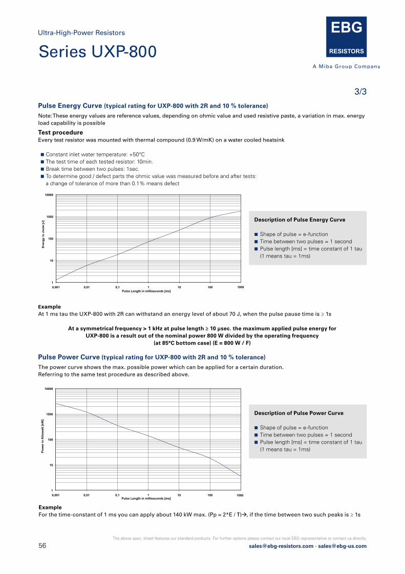
56 [email protected] · [email protected]
The above spec. sheet features our standard products. For further options please contact our local EBG representative or contact us directly.
3/3
Pulse Energy Curve (typical rating for UXP-800 with 2R and 10 % tolerance)
Note: These energy values are reference values, depending on ohmic value and used resistive paste, a variation in max. energyload capability is possible
Pulse Power Curve (typical rating for UXP-800 with 2R and 10 % tolerance)
The power curve shows the max. possible power which can be applied for a certain duration.Referring to the same test procedure as described above.
Test procedureEvery test resistor was mounted with thermal compound (0.9 W/mK) on a water cooled heatsink
Constant inlet water temperature: +50°C The test time of each tested resistor: 10min. Break time between two pulses: 1sec. To determine good / defect parts the ohmic value was measured before and after tests: a change of tolerance of more than 0.1% means defect
ExampleAt 1 ms tau the UXP-800 with 2R can withstand an energy level of about 70 J, when the pulse pause time is ≥ 1s
At a symmetrical frequency > 1 kHz at pulse length ≥ 10 μsec. the maximum applied pulse energy forUXP-800 is a result out of the nominal power 800 W divided by the operating frequency
(at 85°C bottom case) (E = 800 W / F)
ExampleFor the time-constant of 1 ms you can apply about 140 kW max. (Pp = 2*E / τ)à, if the time between two such peaks is ≥ 1s
Description of Pulse Energy Curve
Shape of pulse = e-function Time between two pulses = 1 second Pulse length [ms] = time constant of 1 tau (1 means tau = 1ms)
Description of Pulse Power Curve
Shape of pulse = e-function Time between two pulses = 1 second Pulse length [ms] = time constant of 1 tau (1 means tau = 1ms)
1
10
100
1000
10000
0,001 0,01 0,1 1 10 100
Ener
gy in
Jou
le [J
]
Pulse Length in milliseconds [ms] 1000
1
10
100
1000
10000
0,001 0,01 0,1 1 10 100
Pow
er in
Kilo
wat
t [kW
]
Pulse Length in milliseconds [ms] 1000
Ultra-High-Power Resistors
Series UXP-800
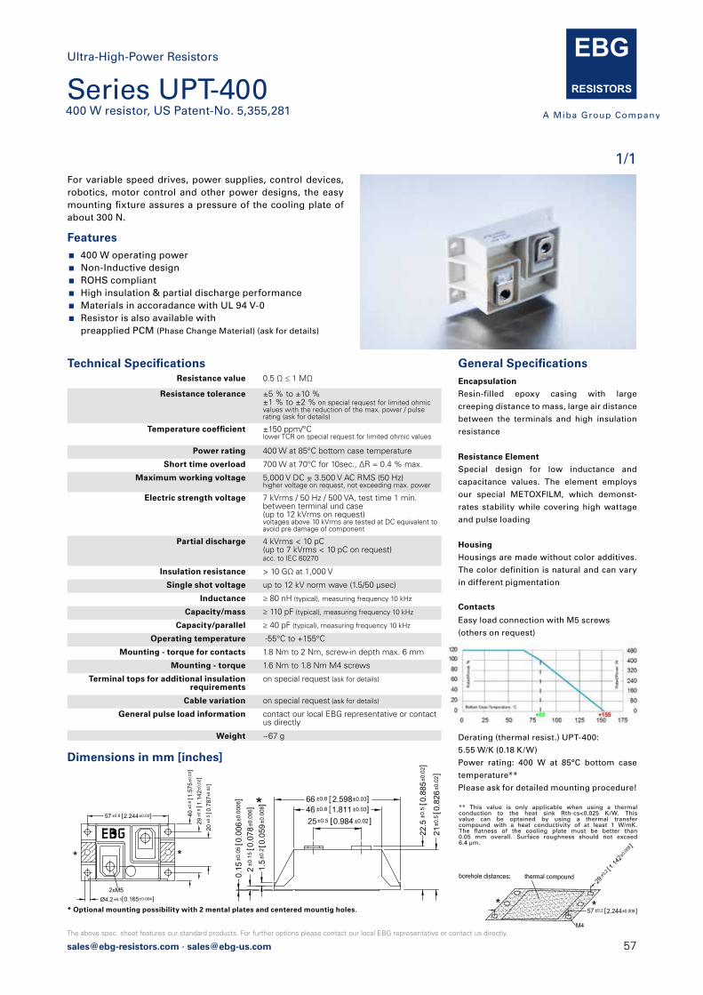
[email protected] · [email protected]
The above spec. sheet features our standard products. For further options please contact our local EBG representative or contact us directly.2017.3 [email protected] · [email protected] · [email protected] Page 1 of 1The above spec. sheet features our standard products. For further options please contact our local EBG representative or contact us directly.
Ultra-High-Power ResistorsSeries UPT-400400 W resistor, US Patent-No. 5,355,281
For variable speed drives, power supplies, control devices, robotics, motor control and other power designs, the easy
cooling plate of about 120 to 160 N.
Features 400 W operating power Non-Inductive design ROHS compliant High insulation & partial discharge performance Materials in accoradance with UL 94 V-0 Resistor is also available with preapplied PCM (Phase Change Material) (ask for details)
EncapsulationResin-lled epoxy casing with large creeping distance to mass, large air distance between the terminals and high insulation resistance
Resistance ElementSpecial design for low inductance and capacitance values. The element employs our special METOXFILM, which demonstrates stability while covering high wattage and pulse loading
Contacts
Easy load connection with M5 screws(others on request)
Dimensions in mm [inches]
Derating (thermal resist.) UPT-400:
5.55 W/K (0.18 K/W)
Power rating: 400 W at 85°C bottom case
temperature**
Please ask for detailed mounting procedure!
Resistance value 0.5 Ω ≤ 1 MΩ
Resistance tolerance ±10 % to ±5 % ±2 % to ±1 % on special request for limited ohmicvalues with the reduction of the max. power / pulse rating (ask for details)
±150 ppm/°Clower TCR on special request for limited ohmic values
Power rating 400 W at 85°C bottom case temperature
Short time overload 700 W at 70°C for 10sec., ∆R = 0.4 % max.
Maximum working voltage 5,000 V DC = 3.500 V AC RMS (50 Hz)higher voltage on request, not exceeding max. power
Electric strength voltage 7 kVrms / 50 Hz / 500 VA, test time 1 min.(up to 12 kVrms on request)voltages above 10 kVrms are tested at DC equivalent to avoid pre damage of componentterminal and case
Partial discharge 4 kVrms < 10 pC(up to 7 kVrms < 10 pC on request)acc. to IEC 60270
Insulation resistance > 10 GΩ at 1,000 V
Single shot voltage up to 12 kV norm wave (1.5/50 μsec)
Inductance ≥ 80 nH (typical), measuring frequency 10 kHz
Capacity/mass ≥ 110 pF (typical), measuring frequency 10 kHz
Capacity/parallel ≥ 40 pF (typical), measuring frequency 10 kHz
Operating temperature -55°C to +155°C
Mounting - max. torque for contacts 2 Nm
Mounting - max. torque 1.8 Nm M4 screws
Terminal tops for additional insulation requirements
on special request (ask for details)
Cable variation on special request (ask for details)
Standard cable type H&S Radox 9 GKW AX 1,5mm2
(other cable types on special request)
General pulse load information contact our local EBG representative or contactus directly
Weight ~120 g
** This value is only applicable when using a thermal conduction to the heat sink Rth-cs<0.025 K/W. This value can be optained by using a thermal transfer compound with a heat conductivity of at least 1 W/mK.
0.05 mm overall. Surface roughness should not exceed 6.4 μm.
Power Rating
46 ±0.8 1.811 ±0.03]66 ±0.8 2.598±0.03]
2±0
.15
0.07
8±0.
006 ]
1.5±
0.2
0.05
9±0.
008 ]
0.15
±0.0
50.
006±
0.00
06]
21±0
.50.
826±
0.02
]22
.50.
885±
0.02
]±0
.5
* Optional mounting possibility with 2 mental plates and centered mountig holes.M4
57 ±0.2 2.244±0.008]
Ø4.2
20±0
.50.
787±
0.02
]29
±0.5
1.14
2±0.
02]
40±0
.81.
575±
0.03
]
57 ±0.8 2.244±0.03]
1/1
Series UPT-400400 W resistor, US Patent-No. 5,355,281
For variable speed drives, power supplies, control devices, robotics, motor control and other power designs, the easy mounting fixture assures a pressure of the cooling plate of about 300 N.
Features 400 W operating power Non-Inductive design ROHS compliant High insulation & partial discharge performance Materials in accoradance with UL 94 V-0 Resistor is also available with
preapplied PCM (Phase Change Material) (ask for details)
General Specifications Encapsulation
Resin-filled epoxy casing with large
creeping distance to mass, large air distance
between the terminals and high insulation
resistance
Resistance Element
Special design for low inductance and
capacitance values. The element employs
our special METOXFILM, which demonst-
rates stability while covering high wattage
and pulse loading
Housing
Housings are made without color additives.
The color definition is natural and can vary
in different pigmentation
Contacts
Easy load connection with M5 screws
(others on request)
Dimensions in mm [inches]
Derating (thermal resist.) UPT-400:
5.55 W/K (0.18 K/W)
Power rating: 400 W at 85°C bottom case
temperature**
Please ask for detailed mounting procedure!
Technical Specifications Resistance value 0.5 Ω ≤ 1 MΩ
Resistance tolerance ±5 % to ±10 % ±1 % to ±2 % on special request for limited ohmicvalues with the reduction of the max. power / pulse rating (ask for details)
Temperature coefficient ±150 ppm/°Clower TCR on special request for limited ohmic values
Power rating 400 W at 85°C bottom case temperature
Short time overload 700 W at 70°C for 10sec., ΔR = 0.4 % max.
Maximum working voltage 5,000 V DC = 3.500 V AC RMS (50 Hz)higher voltage on request, not exceeding max. power
Electric strength voltage 7 kVrms / 50 Hz / 500 VA, test time 1 min. between terminal und case (up to 12 kVrms on request)voltages above 10 kVrms are tested at DC equivalent to avoid pre damage of component
Partial discharge 4 kVrms < 10 pC(up to 7 kVrms < 10 pC on request)acc. to IEC 60270
Insulation resistance > 10 GΩ at 1,000 V
Single shot voltage up to 12 kV norm wave (1.5/50 μsec)
Inductance ≥ 80 nH (typical), measuring frequency 10 kHz
Capacity/mass ≥ 110 pF (typical), measuring frequency 10 kHz
Capacity/parallel ≥ 40 pF (typical), measuring frequency 10 kHz
Operating temperature -55°C to +155°C
Mounting - torque for contacts 1.8 Nm to 2 Nm, screw-in depth max. 6 mm
Mounting - torque 1.6 Nm to 1.8 Nm M4 screws
Terminal tops for additional insulation requirements
on special request (ask for details)
Cable variation on special request (ask for details)
General pulse load information contact our local EBG representative or contactus directly
Weight ~67 g
** This value is only applicable when using a thermal conduction to the heat sink Rth-cs<0.025 K/W. This value can be optained by using a thermal transfer compound with a heat conductivity of at least 1 W/mK. The flatness of the cooling plate must be better than 0.05 mm overall. Surface roughness should not exceed 6.4 μm.
* Optional mounting possibility with 2 mental plates and centered mountig holes.
2017.3 [email protected] · [email protected] · [email protected] Page 1 of 1The above spec. sheet features our standard products. For further options please contact our local EBG representative or contact us directly.
Ultra-High-Power ResistorsSeries UPT-400400 W resistor, US Patent-No. 5,355,281
For variable speed drives, power supplies, control devices, robotics, motor control and other power designs, the easy
cooling plate of about 120 to 160 N.
Features 400 W operating power Non-Inductive design ROHS compliant High insulation & partial discharge performance Materials in accoradance with UL 94 V-0 Resistor is also available with preapplied PCM (Phase Change Material) (ask for details)
EncapsulationResin-lled epoxy casing with large creeping distance to mass, large air distance between the terminals and high insulation resistance
Resistance ElementSpecial design for low inductance and capacitance values. The element employs our special METOXFILM, which demonstrates stability while covering high wattage and pulse loading
Contacts
Easy load connection with M5 screws(others on request)
Dimensions in mm [inches]
Derating (thermal resist.) UPT-400:
5.55 W/K (0.18 K/W)
Power rating: 400 W at 85°C bottom case
temperature**
Please ask for detailed mounting procedure!
Resistance value 0.5 Ω ≤ 1 MΩ
Resistance tolerance ±10 % to ±5 % ±2 % to ±1 % on special request for limited ohmicvalues with the reduction of the max. power / pulse rating (ask for details)
±150 ppm/°Clower TCR on special request for limited ohmic values
Power rating 400 W at 85°C bottom case temperature
Short time overload 700 W at 70°C for 10sec., ∆R = 0.4 % max.
Maximum working voltage 5,000 V DC = 3.500 V AC RMS (50 Hz)higher voltage on request, not exceeding max. power
Electric strength voltage 7 kVrms / 50 Hz / 500 VA, test time 1 min.(up to 12 kVrms on request)voltages above 10 kVrms are tested at DC equivalent to avoid pre damage of componentterminal and case
Partial discharge 4 kVrms < 10 pC(up to 7 kVrms < 10 pC on request)acc. to IEC 60270
Insulation resistance > 10 GΩ at 1,000 V
Single shot voltage up to 12 kV norm wave (1.5/50 μsec)
Inductance ≥ 80 nH (typical), measuring frequency 10 kHz
Capacity/mass ≥ 110 pF (typical), measuring frequency 10 kHz
Capacity/parallel ≥ 40 pF (typical), measuring frequency 10 kHz
Operating temperature -55°C to +155°C
Mounting - max. torque for contacts 2 Nm
Mounting - max. torque 1.8 Nm M4 screws
Terminal tops for additional insulation requirements
on special request (ask for details)
Cable variation on special request (ask for details)
Standard cable type H&S Radox 9 GKW AX 1,5mm2
(other cable types on special request)
General pulse load information contact our local EBG representative or contactus directly
Weight ~120 g
** This value is only applicable when using a thermal conduction to the heat sink Rth-cs<0.025 K/W. This value can be optained by using a thermal transfer compound with a heat conductivity of at least 1 W/mK.
0.05 mm overall. Surface roughness should not exceed 6.4 μm.
Power Rating
46 ±0.8 1.811 ±0.03]66 ±0.8 2.598±0.03]
2±0
.15
0.07
8±0.
006 ]
1.5±
0.2
0.05
9±0.
008 ]
0.15
±0.0
50.
006±
0.00
06]
21±0
.50.
826±
0.02
]22
.50.
885±
0.02
]±0
.5
* Optional mounting possibility with 2 mental plates and centered mountig holes.M4
57 ±0.2 2.244±0.008]
Ø4.2
20±0
.50.
787±
0.02
]29
±0.5
1.14
2±0.
02]
40±0
.81.
575±
0.03
]
57 ±0.8 2.244±0.03]
Ultra-High-Power Resistors
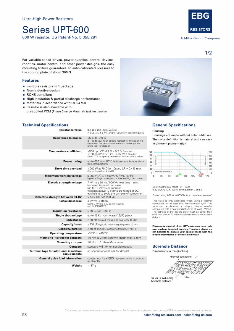
58 [email protected] · [email protected]
The above spec. sheet features our standard products. For further options please contact our local EBG representative or contact us directly.
Series UPT-600600 W resistor, US Patent-No. 5,355,281
1/2For variable speed drives, power supplies, control devices, robotics, motor control and other power designs, the easy mounting fixture guarantees an auto-calibrated pressure to the cooling plate of about 300 N.
Features multiple resistors in 1 package Non-Inductive design ROHS compliant High insulation & partial discharge performance Materials in accordance with UL 94 V-0 Resistor is also available with
preapplied PCM (Phase Change Material) (ask for details)
Technical Specifications Resistance value 0.1 Ω ≤ 0.2 Ω (HC-version)
> 0.2 Ω ≤ 1.5 MΩ (higher values on special request)
Resistance tolerance ±5 % to ±10 %±1 % to ±2 % on special request for limited ohmic value with the reduction of the max. power / pulserating (ask for details)
Temperature coefficient ±500 ppm/°C (0.1 Ω ≤ 0.2 Ω) Standard±150 ppm/°C (> 0.2 Ω ≤ 1.5 MΩ) Standardlower TCR on special request for limited ohmic values
Power rating up to 600 W at 85°C bottom case temperature (see configurations)
Short time overload 1,000 W at 70°C for 10sec., ΔR = 0.4% max.(for configuration 2 and 3)
Maximum working voltage 5,000 V DC = 3.500 V AC RMS (50 Hz)higher voltage on request, not exceeding max. power
Electric strength voltage 7 kVrms / 50 Hz / 500 VA, test time 1 min.between terminal und case (up to 12 kVrms on request)voltages above 10 kVrms are tested at DC equivalent to avoid pre damage of component
Dielectric strength between R1-R2 > 5 kV DC (for conf. 4)Partial discharge 4 kVrms < 10 pC
(up to 7 kVrms < 10 pC on request)acc. to IEC 60270
Insulation resistance > 10 GΩ at 1,000 V
Single shot voltage up to 12 kV norm wave (1.5/50 μsec)
Inductance ≥ 80 nH (typical), measuring frequency 10 kHz
Capacity/mass ≥ 110 pF (typical), measuring frequency 10 kHz
Capacity/parallel ≥ 40 pF (typical), measuring frequency 10 kHz
Operating temperature -55°C to +155°C
Mounting - torque for contacts 1.8 Nm to 2 Nm, screw-in depth max. 6 mm
Mounting - torque 1.6 Nm to 1.8 Nm M4 screws
Contacts standard M5 (M4 on special request)
Terminal tops for additional insulation requirements
on special request (ask for details)
General pulse load information contact our local EBG representative or contactus directly
Weight ~137 g
Derating (thermal resist.) UPT-600:8.33 W/K (0.12 K/W) for configuration 2 and 3
Power rating: 600 W at 85°C bottom case temperature*
This value is only applicable when using a thermal conduction to the heat sink Rth-cs<0.025 K/W. This value can be obtained by using a thermal transfer compound with a heat conductivity of at least 1 W/mK. The flatness of the cooling plate must be better than 0.05 mm overall. Surface roughness should not exceed 6.4 μm.
Please note most all of our UPT customers have their own custom designed drawing. Therefore please do not hesitate to discuss your special needs with the local representative or contact us directly.
Borehole Distance
Ultra-High-Power Resistors
General Specifications Housing
Housings are made without color additives.
The color definition is natural and can vary
in different pigmentation
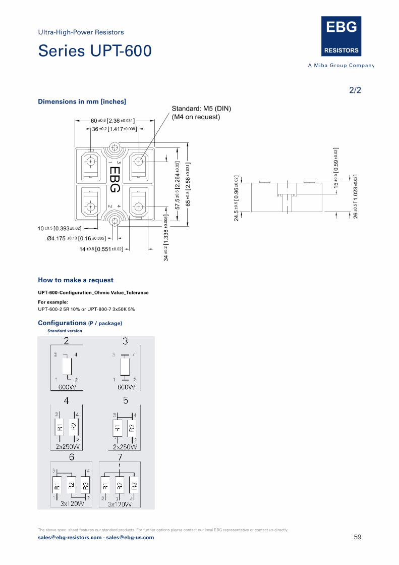
[email protected] · [email protected]
The above spec. sheet features our standard products. For further options please contact our local EBG representative or contact us directly.
How to make a request
UPT-600-Configuration_Ohmic Value_Tolerance
For example:
UPT-600-2 5R 10% or UPT-800-7 3x50K 5%
Dimensions in mm [inches]
(P / package)Standard version
Ultra-High-Power ResistorsSeries UPT-600600 W resistor, US Patent-No. 5,355,281
The above spec. sheet features our standard products. For further options please contact our local EBG representative or contact us directly.
2017.3 [email protected] · [email protected] · [email protected] Page 1 of 2
How to make a request
UPT-600-Configuration_Ohmic Value_Tolerance
For example:
UPT-600-2 5R 10% or UPT-800-7 3x50K 5%
Dimensions in mm [inches]
Configurations (P / package)Standard version
2/2
Ultra-High-Power Resistors
Series UPT-600
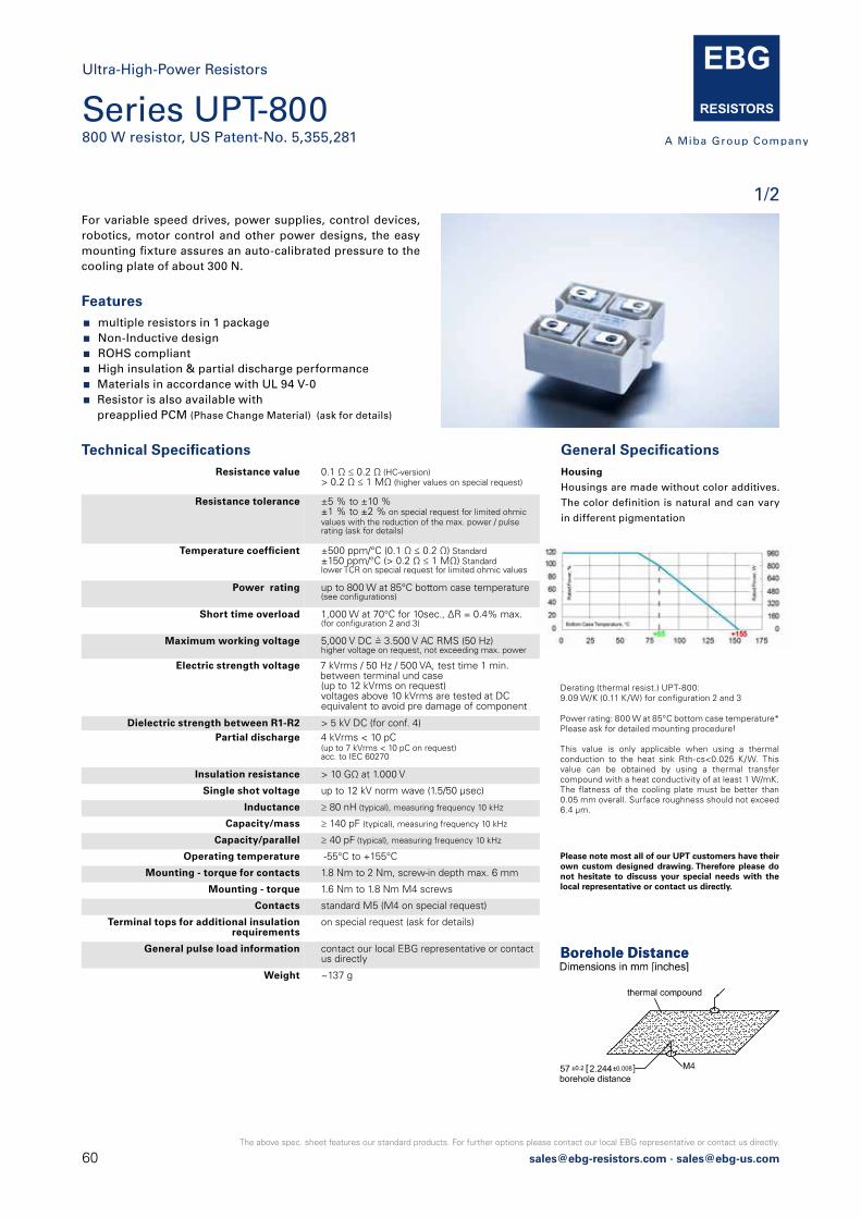
60 [email protected] · [email protected]
The above spec. sheet features our standard products. For further options please contact our local EBG representative or contact us directly.
This value is only applicable when using a thermal conduction to the heat sink Rth-cs<0.025 K/W. This value can be obtained by using a thermal transfer compound with a heat conductivity of at least 1 W/mK. The flatness of the cooling plate must be better than 0.05 mm overall. Surface roughness should not exceed 6.4 μm.
Please note most all of our UPT customers have their own custom designed drawing. Therefore please do not hesitate to discuss your special needs with the local representative or contact us directly.
For variable speed drives, power supplies, control devices, robotics, motor control and other power designs, the easy mounting fixture assures an auto-calibrated pressure to the cooling plate of about 300 N.
Features multiple resistors in 1 package Non-Inductive design ROHS compliant High insulation & partial discharge performance Materials in accordance with UL 94 V-0 Resistor is also available with
preapplied PCM (Phase Change Material) (ask for details)
Derating (thermal resist.) UPT-800:9.09 W/K (0.11 K/W) for configuration 2 and 3
Power rating: 800 W at 85°C bottom case temperature*Please ask for detailed mounting procedure!
Technical Specifications Resistance value 0.1 Ω ≤ 0.2 Ω (HC-version)
> 0.2 Ω ≤ 1 MΩ (higher values on special request)
Resistance tolerance ±5 % to ±10 %±1 % to ±2 % on special request for limited ohmic values with the reduction of the max. power / pulserating (ask for details)
Temperature coefficient ±500 ppm/°C (0.1 Ω ≤ 0.2 Ω) Standard±150 ppm/°C (> 0.2 Ω ≤ 1 MΩ) Standardlower TCR on special request for limited ohmic values
Power rating up to 800 W at 85°C bottom case temperature (see configurations)
Short time overload 1,000 W at 70°C for 10sec., ΔR = 0.4% max.(for configuration 2 and 3)
Maximum working voltage 5,000 V DC = 3.500 V AC RMS (50 Hz)higher voltage on request, not exceeding max. power
Electric strength voltage 7 kVrms / 50 Hz / 500 VA, test time 1 min. between terminal und case(up to 12 kVrms on request)voltages above 10 kVrms are tested at DC equivalent to avoid pre damage of component
Dielectric strength between R1-R2 > 5 kV DC (for conf. 4)Partial discharge 4 kVrms < 10 pC
(up to 7 kVrms < 10 pC on request)acc. to IEC 60270
Insulation resistance > 10 GΩ at 1.000 V
Single shot voltage up to 12 kV norm wave (1.5/50 μsec)
Inductance ≥ 80 nH (typical), measuring frequency 10 kHz
Capacity/mass ≥ 140 pF (typical), measuring frequency 10 kHz
Capacity/parallel ≥ 40 pF (typical), measuring frequency 10 kHz
Operating temperature -55°C to +155°C
Mounting - torque for contacts 1.8 Nm to 2 Nm, screw-in depth max. 6 mm
Mounting - torque 1.6 Nm to 1.8 Nm M4 screws
Contacts standard M5 (M4 on special request)
Terminal tops for additional insulation requirements
on special request (ask for details)
General pulse load information contact our local EBG representative or contactus directly
Weight ~137 g
Borehole Distance
Series UPT-800800 W resistor, US Patent-No. 5,355,281
1/2
* This value is only applicable when using a thermal conduction to the heat sink Rth-cs<0.025 K/W. This value can be obtained by using a thermal transfer compound with a heat conductivity of at least 1 W/mK. The flatness of the cooling plate must be better than 0.05 mm overall. Surface roughness should not exceed 6.4 μm.
Please note most all of our UPT customers have their own custom designed drawing. Therefore please do not hesitate to discuss your special needs with the local representative or contact us directly.
Ultra-High-Power ResistorsSeries UPT-800800 W resistor, US Patent-No. 5,355,281
For variable speed drives, power supplies, control devices, robotics, motor control and other power designs, the easy mounting fixture assures an auto-calibrated pressure to the cooling plate of about 120 to 160 N.
Features 1x 800 W / 2x 300 W / 3x 150 W operating power Non-Inductive design ROHS compliant High insulation & partial discharge performance Materials in accordance with UL 94 V-0 Resistor is also available with preapplied PCM (Phase Change Material) (ask for details)
Derating (thermal resist.) UPT-800:9.09 W/K (0.11 K/W) for configuration 2 and 3
Power rating: 800 W at 85°C bottom case temperature*Please ask for detailed mounting procedure!
Power RatingTechnical Specifications Resistance value 0.1 Ω ≤ 0.2 Ω (HC-version)
> 0.2 Ω ≤ 1 MΩ (higher values on special request)
Resistance tolerance ±10 % to ±5 % ±2 % to ±1 % on special request for limited ohmic values with the reduction of the max. power / pulserating (ask for details)
Temperature coefficient ±500 ppm/°C (0.1 Ω ≤ 0.2 Ω) Standard±150 ppm/°C (> 0.2 Ω ≤ 1 MΩ) Standardlower TCR on special request for limited ohmic values
Power rating up to 800 W at 85°C bottom case temperature (see configurations)
Short time overload 1,000 W at 70°C for 10sec., ΔR = 0.4% max.(for configuration 2 and 3)
Maximum working voltage 5,000 V DC = 3.500 V AC RMS (50 Hz)higher voltage on request, not exceeding max. power
Electric strength voltage 7 kVrms / 50 Hz / 500 VA, test time 1 min.(up to 12 kVrms on request)voltages above 10 kVrms are tested at DC equivalent to avoid pre damage of componentterminal and case
Dielectric strength between R1-R2 > 5 kV DCPartial discharge 4 kVrms < 10 pC
(up to 7 kVrms < 10 pC on request)acc. to IEC 60270
Insulation resistance > 10 GΩ at 1.000 V
Single shot voltage up to 12 kV norm wave (1.5/50 μsec)
Inductance ≥ 80 nH (typical), measuring frequency 10 kHz
Capacity/mass ≥ 140 pF (typical), measuring frequency 10 kHz
Capacity/parallel ≥ 40 pF (typical), measuring frequency 10 kHz
Operating temperature -55°C to +155°C
Mounting - max. torque for contacts 2 Nm
Mounting - max. torque 1.8 Nm M4 screws
Contacts standard M5 (M4 on special request)
Terminal tops for additional insulation requirements & cable variation
on special request (ask for details)
Cable variation on special request (ask for details)
Standard cable type H&S Radox 9 GKW AX 1,5mm² (other cable types on special request)
General pulse load information contact our local EBG representative or contactus directly
Weight ~137 g
The above spec. sheet features our standard products. For further options please contact our local EBG representative or contact us directly.
2017.3 [email protected] · [email protected] · [email protected] Page 1 of 2
Borehole Distance
Ultra-High-Power Resistors
General Specifications Housing
Housings are made without color additives.
The color definition is natural and can vary
in different pigmentation
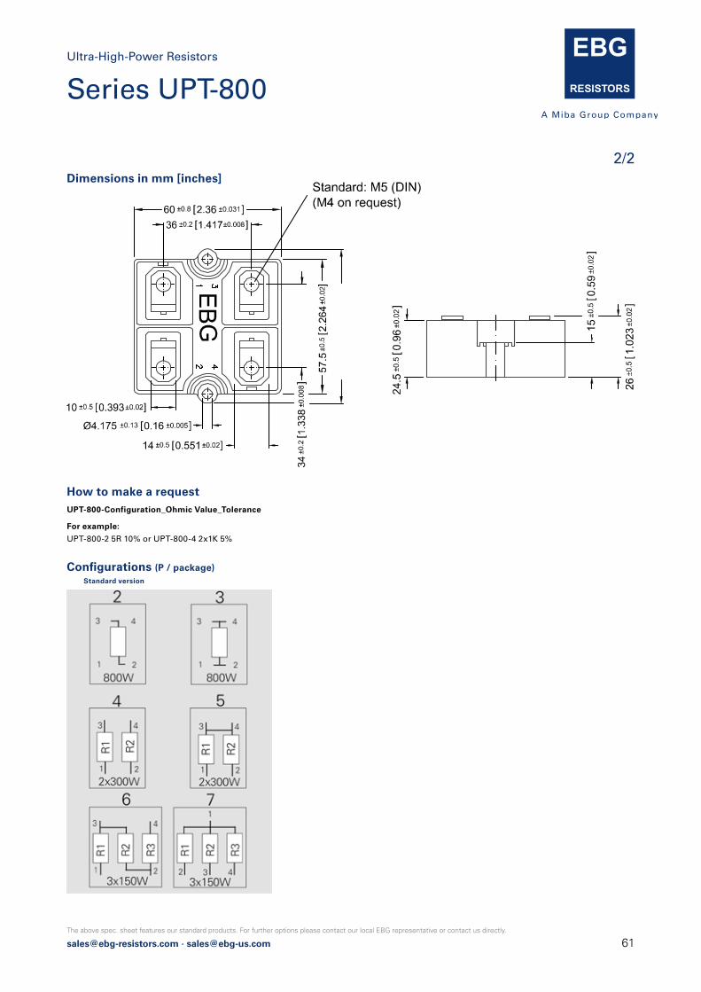
[email protected] · [email protected]
The above spec. sheet features our standard products. For further options please contact our local EBG representative or contact us directly.
Dimensions in mm [inches]
Configurations (P / package)Standard version
How to make a request UPT-800-Configuration_Ohmic Value_Tolerance
For example:
UPT-800-2 5R 10% or UPT-800-4 2x1K 5%
2/2
Ultra-High-Power Resistors
Series UPT-800

62 [email protected] · [email protected]
The above spec. sheet features our standard products. For further options please contact our local EBG representative or contact us directly.
1/2
Series ULX-600 (very low component height)600 W resistor, US Patent-No. 5,355,281
For variable speed drives, power supplies, control devices,robotics, motor control and other power designs.
General Specifications Electric supportHigh-purity ceramic metalized with EBG
ALTOX film on the bottom for better heat
transfer and optimum discharge
EncapsulationResin-filled epoxy casing. High insulation
resistance (CTI 600), high dielectric strength
and partial discharge capability
Resistance ElementSpecial design for low inductance and
capacitance values. The element employs
our special METOXFILM, which demonst-
rates stability while covering high wattage
and pulse loading
Housing
Housings are made without color additives.
The color definition is natural and can vary
in different pigmentation
Technical Specifications Resistance value 0.1 Ω ≤ 0.2 Ω (HC-version)
> 0.2 Ω ≤ 1.5 MΩ (higher values on special request)
Resistance tolerance ±5 % to ±10 %±1 % to ±2 % on special request for limited ohmic values with the reduction of the max. power / pulse rating (ask for details)
Temperature coefficient ±500 ppm/°C (0.1 Ω ≤ 0.2 Ω) standard±150 ppm/°C (> 0.2 Ω ≤ 1.5 MΩ) standardlower TCR on special request for limited ohmic values
Power rating up to 600 W at 85°C bottom case temperature (see configurations)
Short time overload 1,000 W at 70°C for 10sec., ΔR = 0.4 % max.(for configuration 2 and 3)
Maximum working voltage 5,000 V DC = 3.500 V AC RMS (50 Hz)higher voltage on request, not exceeding max. power
Electric strength voltage 7 kVrms / 50 Hz / 500 VA, test time 1 minbetween terminal und case (up to 12 kVrms on request)voltages above 10 kVrms are tested at DC equivalent to avoid pre damage of component
Partial discharge 4 kVrms < 10 pC(up to 7 kVrms < 10 pC on request)acc. to IEC 60270
Peak current up to 1,500 A depending on pulse length and frequency (ask for details)
Insulation resistance > 10 G at 1,000 V
Single shot voltage up to 12 kV norm wave (1.5/50 μsec)
Inductance ≥ 80 nH (typical), measuring frequency 10 kHz
Capacity/mass ≥ 110 pF (typical), measuring frequency 10 kHz
Capacity/parallel ≥ 40 pF (typical), measuring frequency 10 kHz
Operating temperature res. body: -55°C to +155°Cstd. cables: -40°C to +120°C(other cables upon request)
Mounting - torque 1.6 Nm to 1.8 Nm M4 screws
Standard cable length 250 mm (other cable lengths on special request)
Standard cable type H&S Radox 9 GKW AX 1,5 mm2(other cable types on special request)
General Pulse Load information contact our local EBG representative or contactus directly
Weight ~92 g depending on cable
Borehole Distance
thermal compound
M4
57 ±0.2 2.244±0.008]
Derating (thermal resist.) ULX-600 8.33 W/K (0.12K/W)
Power rating: 600 W at 85°C bottom case temperature*
Please ask for detailed mounting procedure!
* This value is only applicable when using a thermal conduction to the heat sink Rth-cs<0.025 K/W. This value can be obtained by using a thermal transfer compound with a heat conductivity of at least 1 W/mK. The flatness of the cooling plate must be better than 0.05 mm overall. Surface roughness should not exceed 6.4 μm.
Features multiple resistors in 1 package Non-Inductive design ROHS compliant High insulation & partial discharge performance Materials in accordance with UL 94 V-0
* This value is only applicable when using a thermal conduction to the heat sink Rth-cs<0.025 K/W. This value can be obtained by using a thermal transfer compound with a heat conductivity of at least 1 W/mK. The flatness of the cooling plate must be better than 0.05 mm overall. Surface roughness should not exceed 6.4 μm.
Please note most all of our UPT customers have their own custom designed drawing. Therefore please do not hesitate to discuss your special needs with the local representative or contact us directly.
Ultra-High-Power ResistorsSeries UPT-800800 W resistor, US Patent-No. 5,355,281
For variable speed drives, power supplies, control devices, robotics, motor control and other power designs, the easy mounting fixture assures an auto-calibrated pressure to the cooling plate of about 120 to 160 N.
Features 1x 800 W / 2x 300 W / 3x 150 W operating power Non-Inductive design ROHS compliant High insulation & partial discharge performance Materials in accordance with UL 94 V-0 Resistor is also available with preapplied PCM (Phase Change Material) (ask for details)
Derating (thermal resist.) UPT-800:9.09 W/K (0.11 K/W) for configuration 2 and 3
Power rating: 800 W at 85°C bottom case temperature*Please ask for detailed mounting procedure!
Power RatingTechnical Specifications Resistance value 0.1 Ω ≤ 0.2 Ω (HC-version)
> 0.2 Ω ≤ 1 MΩ (higher values on special request)
Resistance tolerance ±10 % to ±5 % ±2 % to ±1 % on special request for limited ohmic values with the reduction of the max. power / pulserating (ask for details)
Temperature coefficient ±500 ppm/°C (0.1 Ω ≤ 0.2 Ω) Standard±150 ppm/°C (> 0.2 Ω ≤ 1 MΩ) Standardlower TCR on special request for limited ohmic values
Power rating up to 800 W at 85°C bottom case temperature (see configurations)
Short time overload 1,000 W at 70°C for 10sec., ΔR = 0.4% max.(for configuration 2 and 3)
Maximum working voltage 5,000 V DC = 3.500 V AC RMS (50 Hz)higher voltage on request, not exceeding max. power
Electric strength voltage 7 kVrms / 50 Hz / 500 VA, test time 1 min.(up to 12 kVrms on request)voltages above 10 kVrms are tested at DC equivalent to avoid pre damage of componentterminal and case
Dielectric strength between R1-R2 > 5 kV DCPartial discharge 4 kVrms < 10 pC
(up to 7 kVrms < 10 pC on request)acc. to IEC 60270
Insulation resistance > 10 GΩ at 1.000 V
Single shot voltage up to 12 kV norm wave (1.5/50 μsec)
Inductance ≥ 80 nH (typical), measuring frequency 10 kHz
Capacity/mass ≥ 140 pF (typical), measuring frequency 10 kHz
Capacity/parallel ≥ 40 pF (typical), measuring frequency 10 kHz
Operating temperature -55°C to +155°C
Mounting - max. torque for contacts 2 Nm
Mounting - max. torque 1.8 Nm M4 screws
Contacts standard M5 (M4 on special request)
Terminal tops for additional insulation requirements & cable variation
on special request (ask for details)
Cable variation on special request (ask for details)
Standard cable type H&S Radox 9 GKW AX 1,5mm² (other cable types on special request)
General pulse load information contact our local EBG representative or contactus directly
Weight ~137 g
The above spec. sheet features our standard products. For further options please contact our local EBG representative or contact us directly.
2017.3 [email protected] · [email protected] · [email protected] Page 1 of 2
Borehole Distance
Ultra-High-Power Resistors

[email protected] · [email protected]
The above spec. sheet features our standard products. For further options please contact our local EBG representative or contact us directly.
2/2
Ab 3.2012 ULX statt NXP als Typenbezeichnung
26 1.023 ]±0.5 ±0.02
20 0.787 ]±0.5 ±0.02
M4
Ab 3.2012 ULX statt NXP als Typenbezeichnung
51.5 2.027 ]
57 2.244 ]66.45 ±0.25 2.616±0.01]
±0.5
±0.0
2
±0.5 ±0.02
±0.5 ±0.02
Test Specifications*
Test Method Tolerance Drift**
Short time overload 1,000 W/10sec. 0.40%
Humidity steady state 56 days/40°C/95% 0.25%
Temp. Cycling -55/+125/5cycles 0.20%
Shock 40g/4,000 times 0.25%
Vibrations 2-500Hz/10g 0.25%
Load life 3,000cyl PN 30 min. on / 30 min off 0.40%
* The test methods are according to IEC 60068-2** The tolerance drift is the possible change of the resistance value because of the certain test
Dimensions in mm [inches]
How to make a request ULX-600-Configuration_Ohmic Value_Tolerance
For example:
ULX-600-2 620R 10% or ULX-600-4 2x15K 5%
Configurations
Ultra-High-Power Resistors
Series ULX-600
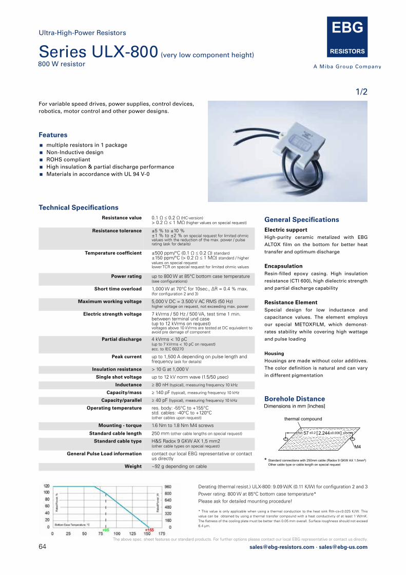
64 [email protected] · [email protected]
The above spec. sheet features our standard products. For further options please contact our local EBG representative or contact us directly.
1/2
Series ULX-800 (very low component height)800 W resistor
Ultra-High-Power Resistors
For variable speed drives, power supplies, control devices,robotics, motor control and other power designs.
Features multiple resistors in 1 package Non-Inductive design ROHS compliant High insulation & partial discharge performance Materials in accordance with UL 94 V-0
Technical Specifications Resistance value 0.1 Ω ≤ 0.2 Ω (HC-version)
> 0.2 Ω ≤ 1 MΩ (higher values on special request)
Resistance tolerance ±5 % to ±10 %±1 % to ±2 % on special request for limited ohmic values with the reduction of the max. power / pulse rating (ask for details)
Temperature coefficient ±500 ppm/°C (0.1 Ω ≤ 0.2 Ω) standard±150 ppm/°C (> 0.2 Ω ≤ 1 MΩ) standard / higher values on special requestlower TCR on special request for limited ohmic values
Power rating up to 800 W at 85°C bottom case temperature (see configurations)
Short time overload 1,000 W at 70°C for 10sec., ΔR = 0.4 % max.(for configuration 2 and 3)
Maximum working voltage 5,000 V DC = 3.500 V AC RMS (50 Hz)higher voltage on request, not exceeding max. power
Electric strength voltage 7 kVrms / 50 Hz / 500 VA, test time 1 min.between terminal und case(up to 12 kVrms on request)voltages above 10 kVrms are tested at DC equivalent to avoid pre damage of component
Partial discharge 4 kVrms < 10 pC(up to 7 kVrms < 10 pC on request)acc. to IEC 60270
Peak current up to 1,500 A depending on pulse length and frequency (ask for details)
Insulation resistance > 10 G at 1,000 V
Single shot voltage up to 12 kV norm wave (1.5/50 μsec)
Inductance ≥ 80 nH (typical), measuring frequency 10 kHz
Capacity/mass ≥ 140 pF (typical), measuring frequency 10 kHz
Capacity/parallel ≥ 40 pF (typical), measuring frequency 10 kHz
Operating temperature res. body: -55°C to +155°Cstd. cables: -40°C to +120°C(other cables upon request)
Mounting - torque 1.6 Nm to 1.8 Nm M4 screws
Standard cable length 250 mm (other cable lengths on special request)
Standard cable type H&S Radox 9 GKW AX 1,5 mm2(other cable types on special request)
General Pulse Load information contact our local EBG representative or contactus directly
Weight ~92 g depending on cable
General Specifications Electric supportHigh-purity ceramic metalized with EBG
ALTOX film on the bottom for better heat
transfer and optimum discharge
EncapsulationResin-filled epoxy casing. High insulation
resistance (CTI 600), high dielectric strength
and partial discharge capability
Resistance ElementSpecial design for low inductance and
capacitance values. The element employs
our special METOXFILM, which demonst-
rates stability while covering high wattage
and pulse loading
Housing
Housings are made without color additives.
The color definition is natural and can vary
in different pigmentation
Borehole Distance
Derating (thermal resist.) ULX-800: 9.09 W/K (0.11 K/W) for configuration 2 and 3
Power rating: 800 W at 85°C bottom case temperature*
Please ask for detailed mounting procedure!
* This value is only applicable when using a thermal conduction to the heat sink Rth-cs<0.025 K/W. This value can be obtained by using a thermal transfer compound with a heat conductivity of at least 1 W/mK. The flatness of the cooling plate must be better than 0.05 mm overall. Surface roughness should not exceed 6.4 μm.
* This value is only applicable when using a thermal conduction to the heat sink Rth-cs<0.025 K/W. This value can be obtained by using a thermal transfer compound with a heat conductivity of at least 1 W/mK. The flatness of the cooling plate must be better than 0.05 mm overall. Surface roughness should not exceed 6.4 μm.
Please note most all of our UPT customers have their own custom designed drawing. Therefore please do not hesitate to discuss your special needs with the local representative or contact us directly.
Ultra-High-Power ResistorsSeries UPT-800800 W resistor, US Patent-No. 5,355,281
For variable speed drives, power supplies, control devices, robotics, motor control and other power designs, the easy mounting fixture assures an auto-calibrated pressure to the cooling plate of about 120 to 160 N.
Features 1x 800 W / 2x 300 W / 3x 150 W operating power Non-Inductive design ROHS compliant High insulation & partial discharge performance Materials in accordance with UL 94 V-0 Resistor is also available with preapplied PCM (Phase Change Material) (ask for details)
Derating (thermal resist.) UPT-800:9.09 W/K (0.11 K/W) for configuration 2 and 3
Power rating: 800 W at 85°C bottom case temperature*Please ask for detailed mounting procedure!
Power RatingTechnical Specifications Resistance value 0.1 Ω ≤ 0.2 Ω (HC-version)
> 0.2 Ω ≤ 1 MΩ (higher values on special request)
Resistance tolerance ±10 % to ±5 % ±2 % to ±1 % on special request for limited ohmic values with the reduction of the max. power / pulserating (ask for details)
Temperature coefficient ±500 ppm/°C (0.1 Ω ≤ 0.2 Ω) Standard±150 ppm/°C (> 0.2 Ω ≤ 1 MΩ) Standardlower TCR on special request for limited ohmic values
Power rating up to 800 W at 85°C bottom case temperature (see configurations)
Short time overload 1,000 W at 70°C for 10sec., ΔR = 0.4% max.(for configuration 2 and 3)
Maximum working voltage 5,000 V DC = 3.500 V AC RMS (50 Hz)higher voltage on request, not exceeding max. power
Electric strength voltage 7 kVrms / 50 Hz / 500 VA, test time 1 min.(up to 12 kVrms on request)voltages above 10 kVrms are tested at DC equivalent to avoid pre damage of componentterminal and case
Dielectric strength between R1-R2 > 5 kV DCPartial discharge 4 kVrms < 10 pC
(up to 7 kVrms < 10 pC on request)acc. to IEC 60270
Insulation resistance > 10 GΩ at 1.000 V
Single shot voltage up to 12 kV norm wave (1.5/50 μsec)
Inductance ≥ 80 nH (typical), measuring frequency 10 kHz
Capacity/mass ≥ 140 pF (typical), measuring frequency 10 kHz
Capacity/parallel ≥ 40 pF (typical), measuring frequency 10 kHz
Operating temperature -55°C to +155°C
Mounting - max. torque for contacts 2 Nm
Mounting - max. torque 1.8 Nm M4 screws
Contacts standard M5 (M4 on special request)
Terminal tops for additional insulation requirements & cable variation
on special request (ask for details)
Cable variation on special request (ask for details)
Standard cable type H&S Radox 9 GKW AX 1,5mm² (other cable types on special request)
General pulse load information contact our local EBG representative or contactus directly
Weight ~137 g
The above spec. sheet features our standard products. For further options please contact our local EBG representative or contact us directly.
2017.3 [email protected] · [email protected] · [email protected] Page 1 of 2
Borehole Distance
2017.1 [email protected] · [email protected] · [email protected] Page 1 of 2
Ultra-High-Power ResistorsSeries ULX-800 (very low component height)800 W resistor
For variable speed drives, power supplies, control devices,robotics, motor control and other power designs.
Electric supportHigh-purity ceramic metalized with EBG
ALTOX film on the bottom for better heat
transfer and optimum discharge
EncapsulationResin-filled epoxy casing. High insulation
resistance (CTI 600), high dielectric strength
and partial discharge capability
Resistance ElementSpecial design for low inductance and
capacitance values. The element employs
our special METOXFILM, which demonst-
rates stability while covering high wattage
and pulse loading
The above spec. sheet features our standard products. For further options please contact our local EBG representative or contact us directly.
Resistance value 0.1 Ω ≤ 0.2 Ω (HC-version)> 0.2 Ω ≤ 1 MΩ (higher values on special request)
Resistance tolerance ±10 % to ±5 %±2 % to ±1 % on special request for limited ohmic values with the reduction of the max. power / pulse rating (ask for details)
±500 ppm/°C (0.1 Ω ≤ 0.2 Ω) standard±150 ppm/°C (> 0.2 Ω ≤ 1 MΩ) standard / higher values on special requestlower TCR on special request for limited ohmic values
Power rating up to 800 W at 85°C bottom case temperature
Short time overload 1,000 W at 70°C for 10sec., ∆R = 0.4 % max.
Maximum working voltage 5,000 V DC = 3.500 V AC RMS (50 Hz)higher voltage on request, not exceeding max. power
Electric strength voltage 7 kVrms / 50 Hz / 500 VA, test time 1 min.(up to 12 kVrms on request)voltages above 10 kVrms are tested at DC equivalent to avoid pre damage of componentterminal and case
Partial discharge 4 kVrms < 10 pC(up to 7 kVrms < 10 pC on request)acc. to IEC 60270
Peak current up to 1,500 A depending on pulse length and frequency (ask for details)
Insulation resistance > 10 G at 1,000 V
Single shot voltage up to 12 kV norm wave (1.5/50 μsec)
Inductance ≥ 80 nH (typical), measuring frequency 10 kHz
Capacity/mass ≥ 140 pF (typical), measuring frequency 10 kHz
Capacity/parallel ≥ 40 pF (typical), measuring frequency 10 kHz
Operating temperature res. body: -55°C to +155°Cstd. cables: -40°C to +120°C(other cables upon request)
Mounting - max. torque 1.8 Nm M4 screws
Standard cable length 250 mm (other cable lengths on special request)
Standard cable type H&S Radox 9 GKW AX 1,5 mm2(other cable types on special request)
General Pulse Load information contact our local EBG representative or contactus directly
Weight ~92 g
Borehole Distance
thermal compound
M4
57 ±0.2 2.244±0.008]
Power Rating
Power rating: 800 W at 85°C bottom case temperature*
Please ask for detailed mounting procedure!
* This value is only applicable when using a thermal conduction to the heat sink Rth-cs<0.025 K/W. This value can be obtained by using a thermal transfer compound with a heat conductivity of at least 1 W/mK.
6.4 μm.
Features 1x 800 W / 2x 300 W / 3x 150 W operation power Non-Inductive design ROHS compliant High insulation & partial discharge performance Materials in accordance with UL 94 V-0 Resistor is also available with preapplied PCM
(Phase Change Material) (ask for details)
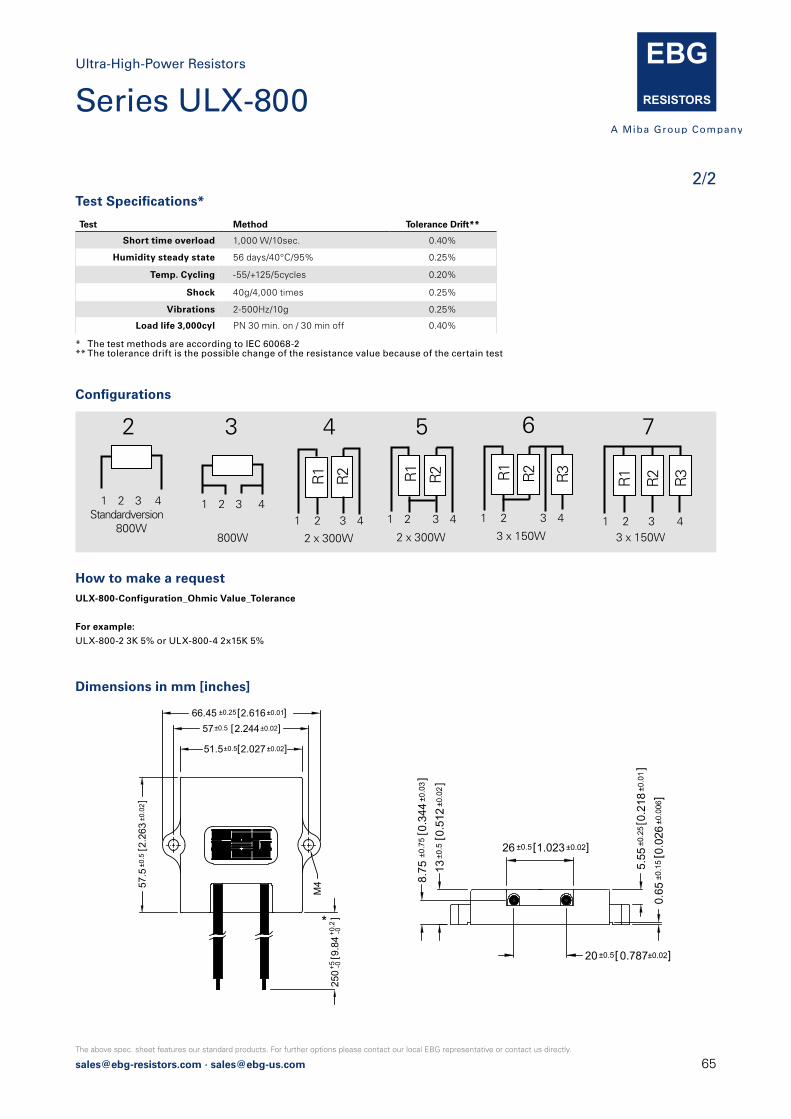
[email protected] · [email protected]
The above spec. sheet features our standard products. For further options please contact our local EBG representative or contact us directly.
2/2
Ultra-High-Power Resistors
Test Specifications*
Test Method Tolerance Drift**
Short time overload 1,000 W/10sec. 0.40%
Humidity steady state 56 days/40°C/95% 0.25%
Temp. Cycling -55/+125/5cycles 0.20%
Shock 40g/4,000 times 0.25%
Vibrations 2-500Hz/10g 0.25%
Load life 3,000cyl PN 30 min. on / 30 min off 0.40%
* The test methods are according to IEC 60068-2** The tolerance drift is the possible change of the resistance value because of the certain test
Dimensions in mm [inches]
How to make a request ULX-800-Configuration_Ohmic Value_Tolerance
For example:
ULX-800-2 3K 5% or ULX-800-4 2x15K 5%
Configurations
1 2 3 4Standardversion
800W
2
R1
R2
1 2 3 4
4
2 x 300W
R1
R2
1 2 3 4
R3
6
3 x 150W
R1
R2
1 2 3 4
5
2 x 300W
1 2 3 4
3
800W
R1
R2 R3
1 2 3 4
7
3 x 150W
Ab 3.2012 ULX statt NXP als Typenbezeichnung
26 1.023 ]±0.5 ±0.02
20 0.787 ]±0.5 ±0.02
M4
Ab 3.2012 ULX statt NXP als Typenbezeichnung
51.5 2.027 ]
57 2.244 ]66.45 ±0.25 2.616±0.01]
±0.5
±0.0
2
±0.5 ±0.02
±0.5 ±0.02
Series ULX-800
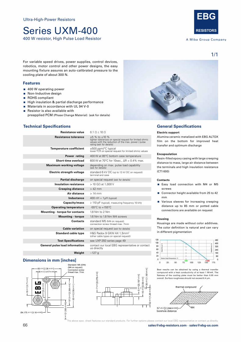
66 [email protected] · [email protected]
The above spec. sheet features our standard products. For further options please contact our local EBG representative or contact us directly.
Series UXM-400400 W resistor, High Pulse Load Resistor
1/1For variable speed drives, power supplies, control devices, robotics, motor control and other power designs, the easy mounting fixture assures an auto-calibrated pressure to the cooling plate of about 300 N.
General Specifications Electric support
Alumina ceramic metalized with EBG ALTOX
film on the bottom for improved heat
transfer and optimum discharge
Encapsulation
Resin-filled epoxy casing with large creeping
distance to mass, large air distance between
the terminals and high insulation resistance
(CTI 600)
Contacts
Easy load connection with M4 or M5
screws
Connector height available from 25 to 42
mm
Various sleeves for increasing creeping
distance up to 85 mm or potted cable
connections are available on request
Housing
Housings are made without color additives.
The color definition is natural and can vary
in different pigmentation
Best results can be obtained by using a thermal transfer compound with a heat conductivity of at least 1 W/mK. The flatness of the cooling plate must be better than 0.05 mm overall. Surface roughness should not exceed 6.4 μm.
Technical Specifications Resistance value 0.1 Ω ≤ 10 Ω
Resistance tolerance ±5 % to ±10 %tighter tolerances on special request for limited ohmicvalues with the reduction of the max. power / pulserating (ask for details)
Temperature coefficient ±500 ppm/°C typical lower TCR on special request for limited ohmic values
Power rating 400 W at 85°C bottom case temperature
Short time overload 600 W at 70°C for 10sec., ΔR = 0.4% max.
Maximum working voltage depending on max. pulse load capability (ask for details)
Electric strength voltage standard 6 kV DC (up to 12 kV DC on request)terminal and case
Partial discharge on special request (ask for details)
Insulation resistance > 10 GΩ at 1,000 V
Creeping distance > 42 mm
Air distance > 14 mm
Inductance 400 nH ÷ 1μH (typical)
Capacity/mass ≥ 110 pF (typical), measuring frequency 10 kHz
Operating temperature -55°C to +155°C
Mounting - torque for contacts 1.8 Nm to 2 Nm
Mounting - torque 1.6 Nm to 1.8 Nm M4 screws
Contacts standard M5 (M4 on request)connection screw thread max. 7mm
Cable variation on special request (ask for details)
Standard cable type H&S Radox 9 GKW AX 1,5mm2
(other cable types on special request)
Test Specifications see UXP-350 series page 49
General pulse load information contact our local EBG representative or contactus directly
Weight ~127 g
Features 400 W operating power Non-Inductive design ROHS compliant High insulation & partial discharge performance Materials in accordance with UL 94 V-0 Resistor is also available with
preapplied PCM (Phase Change Material) (ask for details)
Dimensions in mm [inches]
Ultra-High-Power Resistors
[email protected] · [email protected]
The above spec. sheet features our standard products. For further options please contact our local EBG representative or contact us directly.
Voltage Dividers and NetworksMTX 2000HVTMTX 10001776-X
67

68 [email protected] · [email protected]
The above spec. sheet features our standard products. For further options please contact our local EBG representative or contact us directly.
1/1
Series MTX 2000up to 50 W and up to 80 kV
Precision High-Voltage Divider
Features up to 80 kV operating voltage up to 50 W operating power Non-Inductive design ROHS compliant
The MTX 2000 series consists of high-quality, high-precision,high-power, high-voltage dividers for use in sophisticated resistor networks. These custom designs support a wide range of resistance value, tight voltage ratios, close tolerances and low TCRs.
B
Ø
G
Wire(tinned copper with nickel barrier)
I N
LDEF
Standard version: (no wire connection)
Wire connection available on special request:
Resistance value see model specifications below
Resistance tolerance see model specifications below
Temperature coefficient see model specifications below
Max. operating temperature -55°C to +125°C
Dielectric strength > 1,000 V (25°C, 75 % relative humidity)
Load life ΔR/R 0.15 % max., 1,000 hours at rated power
Moisture resistance ΔR/R 0.25 % max.
Thermal shock ΔR/R 0.2 % max.
Encapsulation standard coating: silicone conformalwe recommend 2xpolyimide coating for use in oil and potted applications (ask for details)
Lead material caps, nickel-plated
Torque 1.8 Nm to 2 Nm for M4, 3.8 Nm to 4 Nm for M8
Connection standard version having no wire tap connection. Pre soldered wire connection available on special request
Weight depending on model no. (ask for details)
Technical Specifications
Model no. L B Ø D E F G I N
2000.23 156 ± 2 14.5 ± 0.2 13.5 ± 0.5 10 ± 0.2 8.5 ± 0.2 5 ± 0.5 M4 1.0 ± 0.1 30.0 ± 1
2000.105 308 ± 2.5 31.8 ± 0.3 30.5 ± 0.5 18 ± 0.2 40 ± 2 7 ± 0.5 M8 1.0 ± 0.1 30.0 ± 1
Dimensions in mm
TCR absolute 50 ppm/°C 25 ppm/°C 15 ppm/°C
Tolerance absolute 0.25 % - 1 % 0.1 % - 1 % 0.1 % - 1%
Model no.P
Wattage 40°C
VVoltage kV DC
TCR ratio 25 ppm/°C 15 ppm/°C 15 / 10 ppm /°C
Tolerance ratio 0.5 % - 0.25% 0.5 % - 0.1% 0.5 % - 0.1 %
2000.23 10 40 R1 + R2 Ratio 2 MΩ – 2 GΩ1:1000 – 1:20 000
20 MΩ – 1 GΩ1:1000 – 1:20 000
20 MΩ – 500 MΩ1:1000 – 1:10 000
2000.105 50 80 R1 + R2 Ratio 20 MΩ – 3 GΩ1:1000 – 1:20 000
20 MΩ – 2 GΩ1:1000 – 1:20 000
20 MΩ – 1 GΩ1:1000 – 1:10 000
Model Specifications
How to make a request Model no._Ohmic Value_abs. & ratio Tolerance_ abs. & ratio TCR_ratio
For example:
MTX 2000.105 500M abs. tol. 2% abs. TCR 25ppm, ratio tol. 1%, ratio TCR 15ppm, 10.000:1
Ratio =R1+R2
R2R1 R2
1 2 3
Lorem ipsum

[email protected] · [email protected]
The above spec. sheet features our standard products. For further options please contact our local EBG representative or contact us directly.
1/1
Series HVT up to 20 kV operating voltage
Precision High-Voltage Divider
Features up to 20 kV operating voltage fully customized values and ratios on request custom designed version available;
maximum ceramic substrate size 4 inch (101.6 mm) Non-Inductive design ROHS compliant
The HVT series of high-voltage dividers is available in six different sizes from 5 kV to 20 kV voltage rating. In these highly reliable components, EBG combines its state-of-the-art high-voltage technology with the unique METOXFILM stability.The HVT series provide tight ratio tolerance, TCR tracking and custom-designed values.
Resistance value 100 M and 200 M standard (other values available on special request)
Resistance tolerance absolute tolerance: ±1 % for all resistors ratio tolerance: down to +/-0.1 %
Temperature coefficient absolute TCR: ±100 ppm/°C (at +85°C ref. to +25°C)lower absolute TCR´s available on request ratio TCR: ±25 ppm/°C (10 ppm/°C on request)
Max. operating temperature -55°C to +155°C
Voltage coefficient typical -0,4 ppm/V
Ratios 1,000:1 or 100:1 (custom ratios available)
Overload 1.5 times rated voltage for 5 sec.ΔR ratio 0.5 % max.
Load Life ratio ΔR with rated voltage applied for 1,000 hours 0.4 % max.
Moisture resistance MIL-STD-202, method 106, ratio ΔR 0.5 % max.
Thermal shock MIL-STD-202, method 107, Cond. C,ratio ΔR 0.25 % max.
Encapsulation HVT-11, -16, -21: silicone conformal with dielectric withstanding voltage of 1,000 V HVT-5, -7, -12: printed silicone coating
Lead material OFHC copper, tin-plated, 0.60 mm
Weight depending on model no. (ask for details)
Technical Specifications
Model no. Voltage Resistance value
PWattage
max.
Dimensions in mm ±0.4 (inches ±0.016)
A B C D
HVT-5 5 kV 100 MΩ 0.3 25.40(1.00)
18.00(0.71)
7.62(0.30)
5.08(0.20)
HVT-7 7 kV 100 MΩ 0.5 25.40(1.00)
18.00(0.71)
12.70(0.50)
5.08(0.20)
HVT-11 10 kV 100 MΩ 1.0 38.10(1.50)
28.00(1.10)
26.40(1.04)
5.08(0.20)
HVT-12 12 kV 200 MΩ 1.0 52.00(2.05)
33.00(1.30)
12.70(0.50)
15.24(0.60)
HVT-16 15 kV 200 MΩ 1.5 52.00(2.05)
42.00(1.65)
18.00(0.71)
5.08(0.20)
HVT-21 20 kV 200 MΩ 2.0 52.00(2.05)
42.00(1.65)
25.40(1.00)
5.08(0.20)
Model Specifications
How to make a request Model no._Ohmic Value_abs. & ratio Tolerance_abs. & ratio TCR_ratio
For example:
HVT-7 100M abs. tol. 1%, abs. TCR 100ppm, ratio tol. 1%, ratio TCR 25ppm 100:1
A
BD
C
10±1
EBGHVT 12

70 [email protected] · [email protected]
The above spec. sheet features our standard products. For further options please contact our local EBG representative or contact us directly.
1/1
Series MTX 1000 up to 32 kV operating voltage
Precision High-Voltage Divider
Features up to 32 kV operating voltage Absolute / ratio tolerance range ±0.1 % to ±1 % Ohmic value and ratios per customer requirements Non-Inductive design ROHS compliant
The MTX 1000 series is used for advanced resistor networkswhere high precision is demanded. Custom designed precision voltage dividers support a wide range of resistance value, voltage ratio, close tolerances, low temperature coefficients and voltage ratings as well as liberty for mechanical dimensions.
Technical SpecificationsResistance value customer specified
Resistance tolerance absolute tolerance: ±0.1 % to ±1 %ratio tolerance: ±0.1 % to ±1 %depending on ohmic value
Temperature coefficient absolute TCR: ±50 ppm/°C to ±15 ppm/°Cratio TCR: ±15 ppm/°C to ±5 ppm/°Cdepending on ohmic value
Ratios standard ratios: 100:1, 1000:1, 10000:1 (others on special request)
Max. operating temperature -55°C to +125°C
Dielectric strength > 1,000 V (25°C, 75 % relative humidity)
Insulation resistance > 10,000 MΩ (500 V, 25°C, 75 % relative humidity)
Overload ΔR/R 0.25 % max. 1.5x Pnom, 5 sec.(do not exceed 1.5x V max.)
Load life ΔR/R 0.15 % max., 1,000 hours at rated power
Moisture resistance ΔR/R 0.25 % max.
Thermal shock ΔR/R 0.2 % max.
Encapsulation standard silicone conformal (U) or glass coating (G)we recommend 2xpolyimide coating for use in oil and potted applications (ask for details)
Lead material tinned copper
Weight depending on model no. (ask for details)
How to make a request Model no._Ohmic Value_abs. & ratio Tolerance_ abs. & ratio TCR_ratio _coating
For example:
MTX 1000.2 20M abs. Tol 0.25%, abs. TCR 25ppm, ratio Tol. 0.1%, ratio TCR 15ppm, 1000:1 U
PWattage
VVoltage kV DC
Dimensions in mm
Model no. L B C D E
1000.2 0.5 8* 26 8 9.1 22.9 5.08
1000.3 1.2 15* 38.5 13 14.2 35.6 7.62
1000.4 1.8 24* 51.5 15.5 16.6 48.3 10.16
1000.5 2.4 32* 77.5 15.5 16.6 73.4 10.16
Model Specifications
* for glass coating and 2xpolyimide coating, when used in open air, please use max. voltage x 0.6 (standard ratings valid when parts used in clean air)
B
E
30 +5
L
max. 3(max. 0.118)
Ø 0.8 (0.032)
D
MTX 1000 C
R2R1
1 2 3
Ratio =R1+R2
R2
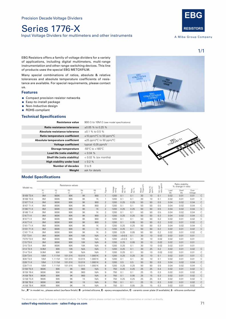
[email protected] · [email protected]
The above spec. sheet features our standard products. For further options please contact our local EBG representative or contact us directly.
Features Compact precision resistor networks Easy-to-install package Non-Inductive design ROHS compliant
EBG Resistors offers a family of voltage dividers for a variety of applications, including digital multimeters, multi-range instrumentation and other range-switching devices. This line of products uses the special EBG METOXFILM.
Resistance value 900 Ω to 10M Ω (see model specifications)
Ratio resistance tolerance ±0.05 % to 0.25 %
Absolute resistance tolerance ±0.1 % to 0.5 %
Ratio temperature coefficient ±10 ppm/°C to 50 ppm/°C
Absolute temperature coefficient ±25 ppm/°C to 50 ppm/°C
Voltage coefficient typical -0,05 ppm/V
Storage temperature -55°C to +165°C
Load life (ratio stability) < 0.04 %
Shelf life (ratio stability) < 0.02 % (six months)
High stability under load < 0.2 %
Number of decades 3 to 6
Weight ask for details
Technical Specifications
for „X“ in model no., please select (surface finish): B - printed silicone, E - epoxy encapsulation, C - ceramic cover plate (if available), S - silicone conformal
Model Specifications
Model no.Resistance values
Figu
re
Volta
ge
ratin
g
Abs
olut
e to
l. %
Rat
io
tol.
%
Abs
ol.
TCpp
m/°
C
Rat
io T
Cpp
m/°
C
Vol.
coef
.ra
tio p
pm/V Ratio stability
% change in ratio
R1Ω
R2Ω
R3Ω
R4Ω
R5Ω
Load life
Shelf life
Over-Voltage
B169 T3-X 9M 900K 90K 9K 900 1 1200 0.1 0.1 30 10 0.1 0.02 0.01 0.01 CB168 T3-X 9M 900K 90K 9K 1K 1 1200 0.1 0.1 30 10 0.1 0.02 0.01 0.01 CE167 T1-X 9M 900K 90K 9K 900 2 1200 0.25 0.25 50 50 0.5 0.04 0.02 0.04 CB167 T1-X 9M 900K 90K 9K 900 2 1200 0.1 0.1 50 50 0.5 0.04 0.02 0.04 CE166 T1-X 9M 900K 90K 9K 1K 2 1200 0.25 0.25 50 50 0.5 0.04 0.02 0.04 CB166 T1-X 9M 900K 90K 9K 1K 2 1200 0.1 0.1 50 50 0.5 0.04 0.02 0.04 CE16 T1-X 9M 900K 90K 9K 900 3 1200 0.25 0.25 50 50 0.3 0.04 0.02 0.04 CB16 T1-X 9M 900K 90K 9K 900 3 1200 0.1 0.1 50 50 0.2 0.02 0.01 0.02 CA16 T1-X 9M 900K 90K 9K 900 3 1200 0.1 0.05 50 50 0.2 0.02 0.01 0.02 CE161 T1-X 9M 900K 90K 9K 1K 3 1200 0.25 0.25 50 50 0.3 0.04 0.02 0.04 CD161 T1-X 9M 900K 90K 9K 1K 3 1200 0.25 0.1 50 50 0.2 0.02 0.01 0.02 CC161 T1-X 9M 900K 90K 9K 1K 3 1200 0.25 0.05 50 50 0.2 0.02 0.01 0.02 CF37 T3-X 9M 900K 90K 10K N/A 4 1200 +0-0.5 0.1 30 10 0.02 0.02 0.01 0.01F379 T3-X 9M 900K 90K 10K N/A 5 1200 +0-0.5 0.1 30 10 0.02 0.02 0.01 0.01C15 T3-X 9M 900K 90K 10K N/A 6 1200 0.25 0.05 30 10 0.02 0.02 0.01 0.01D15 T3-X 9M 900K 90K 10K N/A 6 1200 0.25 0.1 30 10 0.02 0.02 0.01 0.01D14 T2-X 9.9M 90K 10K N/A N/A 7 1200 0.25 0.1 30 25 0.2 0.02 0.01 0.02 CD14 T3-X 9.9M 90K 10K N/A N/A 7 1200 0.25 0.1 30 10 0.02 0.02 0.01 0.01 CE39 T3-X 10M 1.111M 101.01K 10.01K 1.0001K 8 1200 0.25 0.25 30 10 0.1 0.02 0.01 0.01 CB39 T3-X 10M 1.111M 101.01K 10.01K 1.0001K 8 1200 0.1 0.1 30 10 0.1 0.02 0.01 0.01 CG39 T1-X 10M 1.111M 101.01K 10.01K 1.0001K 8 1200 0.5 0.5 50 50 0.5 0.04 0.02 0.04 CE39 T1-X 10M 1.111M 101.01K 10.01K 1.0001K 8 1200 0.25 0.25 50 50 0.5 0.04 0.02 0.04 CE159 T5-X 900K 90K 9K 900 N/A 9 750 0.25 0.25 25 25 0.4 0.02 0.01 0.02 CB159 T6-X 900K 90K 9K 900 N/A 9 750 0.1 0.1 25 15 0.3 0.02 0.01 0.02 CA159 T6-X 900K 90K 9K 900 N/A 9 750 0.1 0.05 25 15 0.3 0.02 0.01 0.02 CG158 T5-X 900K 90K 9K 1K N/A 9 750 0.25 0.25 25 25 0.4 0.02 0.01 0.02 CB158 T6-X 900K 90K 9K 1K N/A 9 750 0.1 0.1 25 15 0.3 0.02 0.01 0.02 CA158 T6-X 900K 90K 9K 1K N/A 9 750 0.1 0.05 25 15 0.3 0.02 0.01 0.02 C
Many special combinations of ratios, absolute & relative tolerances and absolute temperature coefficients of resis-tance are available. For special requirements, please contact us.
1/1
Series 1776-X Input Voltage Dividers for multimeters and other instruments
Precision Decade Voltage Dividers
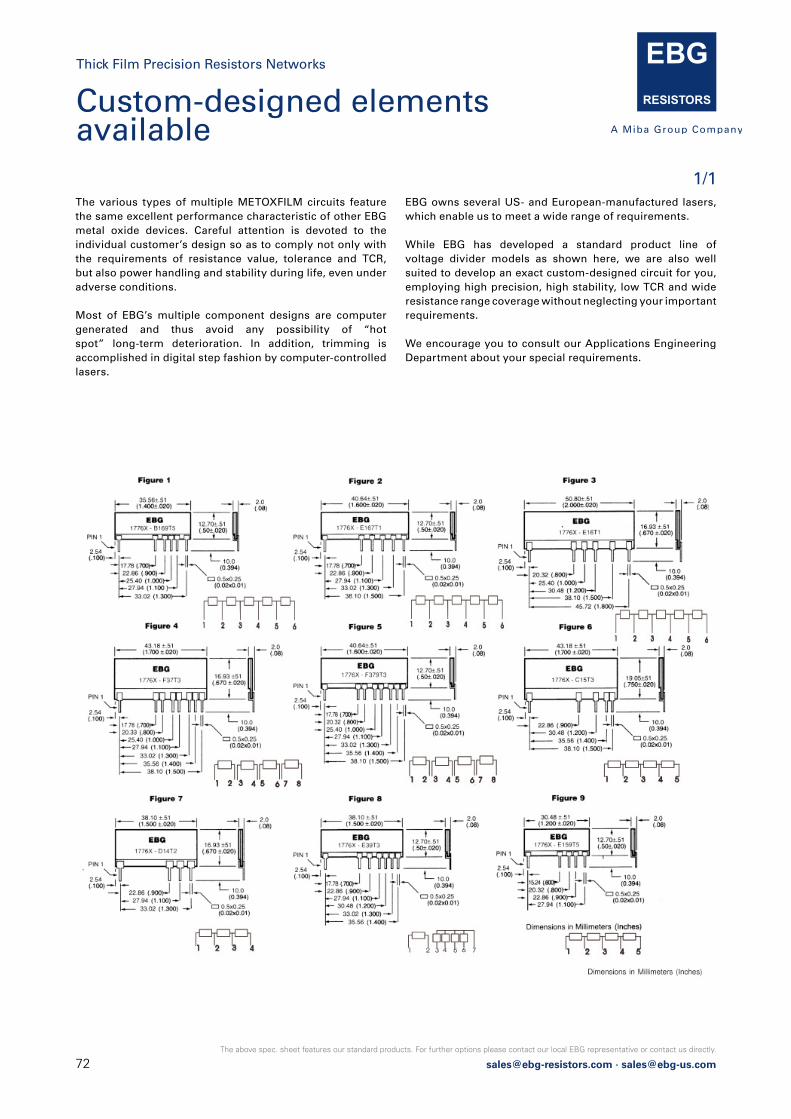
72 [email protected] · [email protected]
The above spec. sheet features our standard products. For further options please contact our local EBG representative or contact us directly.
The various types of multiple METOXFILM circuits feature the same excellent performance characteristic of other EBG metal oxide devices. Careful attention is devoted to the individual customer’s design so as to comply not only with the requirements of resistance value, tolerance and TCR, but also power handling and stability during life, even under adverse conditions.
Most of EBG’s multiple component designs are computer generated and thus avoid any possibility of “hot spot” long-term deterioration. In addition, trimming is accomplished in digital step fashion by computer-controlled lasers.
EBG owns several US- and European-manufactured lasers, which enable us to meet a wide range of requirements.
While EBG has developed a standard product line of voltage divider models as shown here, we are also well suited to develop an exact custom-designed circuit for you, employing high precision, high stability, low TCR and wide resistance range coverage without neglecting your important requirements.
We encourage you to consult our Applications Engineering Department about your special requirements.
1/1
Custom-designed elements available
Thick Film Precision Resistors Networks

[email protected] · [email protected]
The above spec. sheet features our standard products. For further options please contact our local EBG representative or contact us directly.
Metal Film
UPR / UPSCEE / NE
73
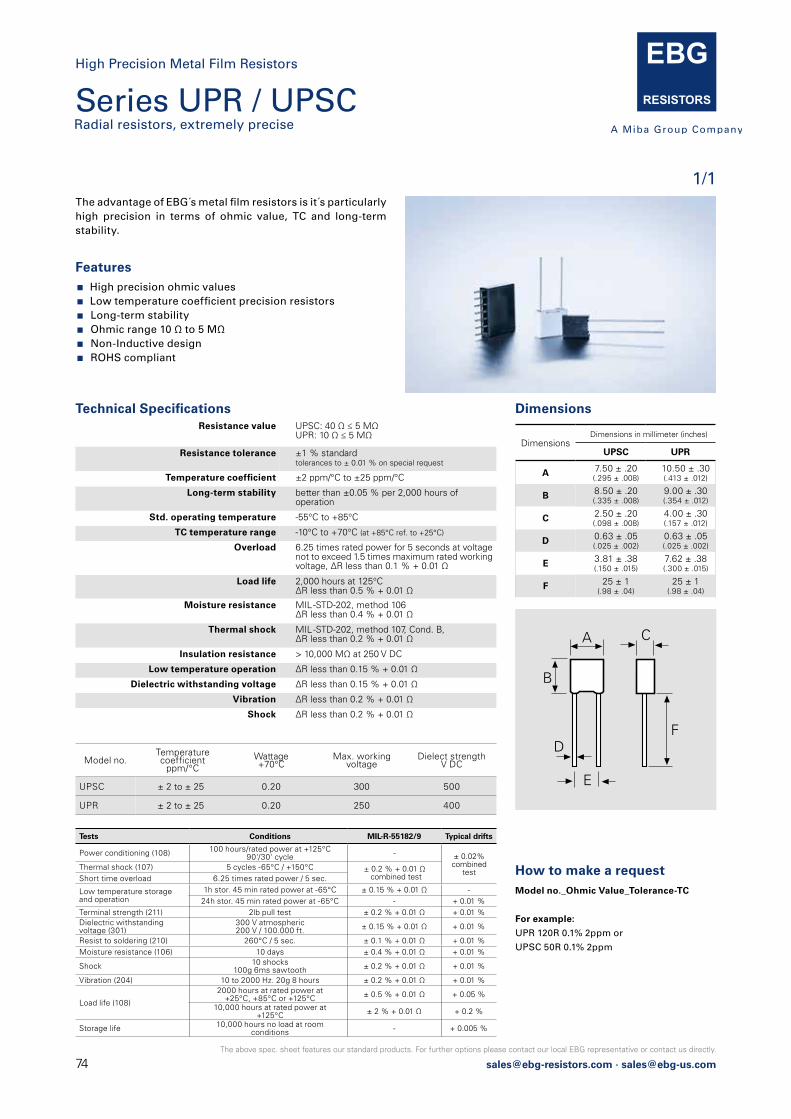
74 [email protected] · [email protected]
The above spec. sheet features our standard products. For further options please contact our local EBG representative or contact us directly.
1/1
Series UPR / UPSCRadial resistors, extremely precise
High Precision Metal Film Resistors
Features High precision ohmic values Low temperature coefficient precision resistors Long-term stability Ohmic range 10 Ω to 5 MΩ Non-Inductive design ROHS compliant
The advantage of EBG´s metal film resistors is it´s particularly high precision in terms of ohmic value, TC and long-term stability.
DimensionsTechnical Specifications
DimensionsDimensions in millimeter (inches)
UPSC UPR
A 7.50 ± .20 (.295 ± .008)
10.50 ± .30 (.413 ± .012)
B 8.50 ± .20 (.335 ± .008)
9.00 ± .30 (.354 ± .012)
C 2.50 ± .20 (.098 ± .008)
4.00 ± .30 (.157 ± .012)
D 0.63 ± .05 (.025 ± .002)
0.63 ± .05 (.025 ± .002)
E 3.81 ± .38 (.150 ± .015)
7.62 ± .38 (.300 ± .015)
F 25 ± 1 (.98 ± .04)
25 ± 1 (.98 ± .04)
How to make a request Model no._Ohmic Value_Tolerance-TC
For example:
UPR 120R 0.1% 2ppm or
UPSC 50R 0.1% 2ppm
Resistance value UPSC: 40 Ω ≤ 5 MΩUPR: 10 Ω ≤ 5 MΩ
Resistance tolerance ±1 % standardtolerances to ± 0.01 % on special request
Temperature coefficient ±2 ppm/°C to ±25 ppm/°C
Long-term stability better than ±0.05 % per 2,000 hours of operation
Std. operating temperature -55°C to +85°C
TC temperature range -10°C to +70°C (at +85°C ref. to +25°C)
Overload 6.25 times rated power for 5 seconds at voltage not to exceed 1.5 times maximum rated working voltage, ΔR less than 0.1 % + 0.01 Ω
Load life 2,000 hours at 125°CΔR less than 0.5 % + 0.01 Ω
Moisture resistance MIL -STD-202, method 106 ΔR less than 0.4 % + 0.01 Ω
Thermal shock MIL -STD-202, method 107, Cond. B, ΔR less than 0.2 % + 0.01 Ω
Insulation resistance > 10,000 MΩ at 250 V DC
Low temperature operation ΔR less than 0.15 % + 0.01 Ω
Dielectric withstanding voltage ΔR less than 0.15 % + 0.01 Ω
Vibration ΔR less than 0.2 % + 0.01 Ω
Shock ΔR less than 0.2 % + 0.01 Ω
Tests Conditions MIL-R-55182/9 Typical drifts
Power conditioning (108) 100 hours/rated power at +125°C 90'/30' cycle - ± 0.02%
combinedtest
Thermal shock (107) 5 cycles -65°C / +150°C ± 0.2 % + 0.01 Ω combined testShort time overload 6.25 times rated power / 5 sec.
Low temperature storageand operation
1h stor. 45 min rated power at -65°C ± 0.15 % + 0.01 Ω -24h stor. 45 min rated power at -65°C - + 0.01 %
Terminal strength (211) 2lb pull test ± 0.2 % + 0.01 Ω + 0.01 %Dielectric withstandingvoltage (301)
300 V atmospheric200 V / 100.000 ft. ± 0.15 % + 0.01 Ω + 0.01 %
Resist to soldering (210) 260°C / 5 sec. ± 0.1 % + 0.01 Ω + 0.01 %Moisture resistance (106) 10 days ± 0.4 % + 0.01 Ω + 0.01 %
Shock 10 shocks100g 6ms sawtooth ± 0.2 % + 0.01 Ω + 0.01 %
Vibration (204) 10 to 2000 Hz. 20g 8 hours ± 0.2 % + 0.01 Ω + 0.01 %
Load life (108)
2000 hours at rated power at+25°C, +85°C or +125°C ± 0.5 % + 0.01 Ω + 0.05 %
10,000 hours at rated power at+125°C ± 2 % + 0.01 Ω + 0.2 %
Storage life 10,000 hours no load at roomconditions - + 0.005 %
Model no.Temperature coefficient
ppm/°CWattage +70°C
Max. working voltage
Dielect strength V DC
UPSC ± 2 to ± 25 0.20 300 500
UPR ± 2 to ± 25 0.20 250 400
A C
B
D
E
F

[email protected] · [email protected]
The above spec. sheet features our standard products. For further options please contact our local EBG representative or contact us directly.
EBG Resistor´s EE series conform dimensionally to the RN series of MIL-R-10509 and the RNR series of MIL-R-55182. All of EBG`s Metal Film Resistor series offer performances that exceed the requirements of both of these specifications. EE series can be used for automatic insertion and/or encapsulation.
Resistance value 10 Ω ≤ 10 MΩ (other values on special request)
Resistance tolerance ±0.02 % to ±1 %
Temperature coefficient ±5 ppm/°C to ±50 ppm/°CTCR referenced to 25°C, ΔR taken at +25°C and +85°C (other TCR on special request)
elements are produced and tested in accordance with MIL-R-150509, MIL-R-55182, MIL-STD-202
Special feature series UAR (ask for details)
Technical Specifications
Model no. Wattage 70°C
Max. continuous oper. Volt.
Resistance values Dimensions in millimeters (inches)
Min. Max. L D A
EE 1/20 0.125 200 10 Ω 2 MΩ 4.30 ± .30 (.169 ± .01)
1.90 ± .30 (.075 ± .01)
.40 ± .05 (.016 ± .002)
EE 1/10 0.250 200 10 Ω 10 MΩ 6.80 ± .30 (.268 ± .01)
2.50 ± .30 (.169 ± .01)
.60 ± .05 (.024 ± .002)
EE 1/8 0.500 250 10 Ω 10 MΩ 10.20 ± .30 (.402 ± .01)
3.80 ± .30 (.149 ± .01)
.60 ± .05 (.024 ± .002)
EE 1/4 0.750 300 10 Ω 10 MΩ 15.10 ± .30 (.594 ± .01)
5.20 ± .30 (.205 ± .01)
.60 ± .05 (.024 ± .002)
EE 1/2 1.000 350 10 Ω 10 MΩ 18.40 ± .30 (.724 ± .01)
6.50 ± .30 (.256 ± .01)
.80 ± .05 (.031 ± .002)
TypeMIL-R-10509
EE 1/20RN55
EE 1/10RN55
EE 1/8RN60
EE 1/4RN65
EE 1/2RN70
Power rating (W at 125°C) .05 .10 .125 .25 .50
Max. working voltage (V) 200 200 250 300 350
EBG Resistor´s NE series features extremely low ranges. As a result of a special proprietary filming method, a nickel film is employed with controlled amounts of other metals, which results in fracturial resistance value availa-bility, but with low temperature coefficient of resistance and high stability.
Model no. Wattage Resistance values Dimensions in millimeters (inches)
Min. Max. L D A
NE 1/10 0.25 0.05 Ω 10 Ω 6.80 ± .30 (.268 ± .01)
2.50 ± .30 (0.98 ± .01)
.60 ± .05 (.024 ± .002)
NE 1/8 0.50 0.05 Ω 10 Ω 10.20 ± .30 (.402 ± .01)
3.80 ± .30 (.149 ± .01)
.60 ± .05 (.024 ± .002)
NE 1/4 1.00 0.05 Ω 10 Ω 15.10 ± .30 (.594 ± .01)
5.20 ± .30 (.205 ± .01)
.60 ± .05 (.024 ± .002)
NE 1/2 1.50 0.05 Ω 10 Ω 18.40 ± .30 (.724 ± .01)
6.50 ± .30 (.256 ± .01)
.80 ± .05 (.031 ± .002)
On special request, EBG Resistor will conduct a
“burn-in“ of these elements for ultimate stability.
Please refer to the UAR (Ultra Accurate Resistor)
series and ask for a detailed datasheet!
Min. 35.0(Min. 1.38)
DIMENSIONS IN MILLIMETERS (INCHES)
DA
EBG
L
10.10.01
50
100
Ohmvalue10 Ohm
Minimum T.C.T.C.ppm/°C
Resistance value 0.05 Ω ≤ 10 Ω (other values on special request)
Resistance tolerance ±0.05 % to ±5 %
Temperature coefficient according to drawing
Operating temperature -55°C to +155°C
Insulation resistance 104 MΩ at 500 V DC
Noise less than 0.05 μV/V
Technical Specifications
How to make a request Model no._Ohmic value_Tolerance_TC
For example:
EE 1/2 10M 0.1% 5ppm or NE 1/8 10R 1% 5%
1/1
Series EEMolded style
High Precision Metal Film Resistors
Series NEMolded style

76 [email protected] · [email protected]
The above spec. sheet features our standard products. For further options please contact our local EBG representative or contact us directly.
Shunts
PCS
76
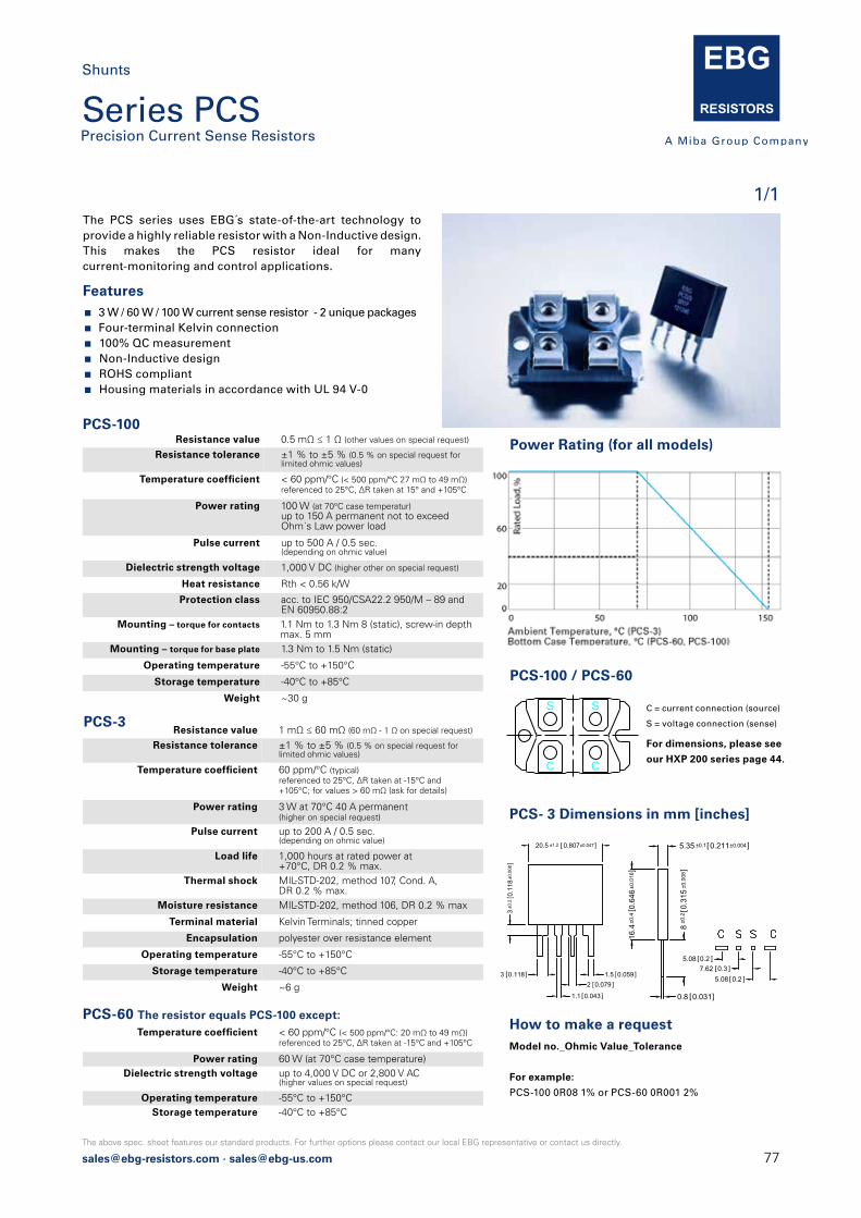
[email protected] · [email protected]
The above spec. sheet features our standard products. For further options please contact our local EBG representative or contact us directly.
PCS-100Resistance value 0.5 mΩ ≤ 1 Ω (other values on special request)
Resistance tolerance ±1 % to ±5 % (0.5 % on special request for limited ohmic values)
Temperature coefficient < 60 ppm/°C (< 500 ppm/°C 27 mΩ to 49 mΩ)referenced to 25°C, ΔR taken at 15° and +105°C
Power rating 100 W (at 70°C case temperatur) up to 150 A permanent not to exceed Ohm´s Law power load
Pulse current up to 500 A / 0.5 sec.(depending on ohmic value)
Dielectric strength voltage 1,000 V DC (higher other on special request)
Heat resistance Rth < 0.56 k/W
Protection class acc. to IEC 950/CSA22.2 950/M – 89 andEN 60950.88:2
Mounting – torque for contacts 1.1 Nm to 1.3 Nm 8 (static), screw-in depth max. 5 mm
Mounting – torque for base plate 1.3 Nm to 1.5 Nm (static)
Operating temperature -55°C to +150°C
Storage temperature -40°C to +85°C
Weight ~30 g
Features 3 W / 60 W / 100 W current sense resistor - 2 unique packages Four-terminal Kelvin connection 100% QC measurement Non-Inductive design ROHS compliant Housing materials in accordance with UL 94 V-0
PCS-3
The PCS series uses EBG´s state-of-the-art technology to provide a highly reliable resistor with a Non-Inductive design.This makes the PCS resistor ideal for many current-monitoring and control applications.
How to make a request Model no._Ohmic Value_Tolerance
For example:
PCS-100 0R08 1% or PCS-60 0R001 2%
Power Rating (for all models)
Resistance value 1 mΩ ≤ 60 mΩ (60 mΩ - 1 Ω on special request) Resistance tolerance ±1 % to ±5 % (0.5 % on special request for
limited ohmic values)
Temperature coefficient 60 ppm/°C (typical)referenced to 25°C, ΔR taken at -15°C and+105°C; for values > 60 mΩ (ask for details)
Power rating 3 W at 70°C 40 A permanent(higher on special request)
Pulse current up to 200 A / 0.5 sec.(depending on ohmic value)
Load life 1,000 hours at rated power at+70°C, DR 0.2 % max.
Thermal shock MIL-STD-202, method 107, Cond. A,DR 0.2 % max.
Moisture resistance MIL-STD-202, method 106, DR 0.2 % max
Terminal material Kelvin Terminals; tinned copper
Encapsulation polyester over resistance element
Operating temperature -55°C to +150°C
Storage temperature -40°C to +85°C
Weight ~6 g
PCS-60 The resistor equals PCS-100 except: Temperature coefficient < 60 ppm/°C (< 500 ppm/°C: 20 mΩ to 49 mΩ)
referenced to 25°C, ΔR taken at -15°C and +105°C
Power rating 60 W (at 70°C case temperature) Dielectric strength voltage up to 4,000 V DC or 2,800 V AC
(higher values on special request)
Operating temperature -55°C to +150°C Storage temperature -40°C to +85°C
PCS-100 / PCS-60
S S
C C
C = current connection (source)
S = voltage connection (sense)
20.5 ±1.2 0.807±0.047]
3 0.118]
3±0
.2 0
.118
±0.0
08]
1.5 0.059 ]
1.1 0.043]
2 0.079]
5.08 0.2 ]7.62 0.3 ]
5.08 0.2 ]
PCS- 3 Dimensions in mm [inches]
For dimensions, please see
our HXP 200 series page 44.
1/1
Series PCS Precision Current Sense Resistors
Shunts
5.35 ±0.1 0.211±0.004]
16.4
±0.4
0.64
6±0
.016
]
0.8 0.031]
8±0
.20.
315
±0.0
08]
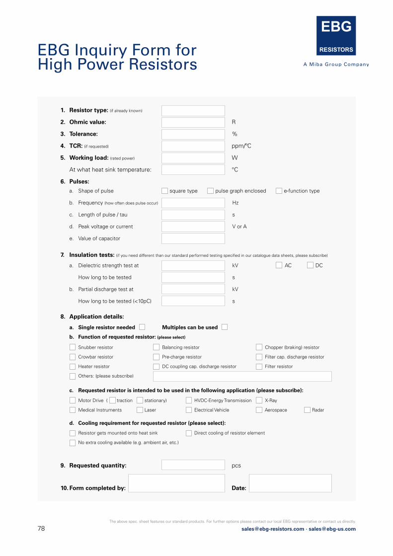
78 [email protected] · [email protected]
The above spec. sheet features our standard products. For further options please contact our local EBG representative or contact us directly.
1. Resistor type: (if already known)
2. Ohmic value: R
3. Tolerance: %
4. TCR: (if requested) ppm/ºC
5. Working load: (rated power) W
At what heat sink temperature: °C
6. Pulses:
9. Requested quantity: pcs
10. Form completed by: Date:
7. Insulation tests: (if you need different than our standard performed testing specifi ed in our catalogue data sheets, please subscribe)
8. Application details:
a. Shape of pulse square type pulse graph enclosed e-function type
b. Frequency (how often does pulse occur) Hz
c. Length of pulse / tau s
d. Peak voltage or current V or A
e. Value of capacitor
a. Dielectric strength test at kV
How long to be tested s
b. Partial discharge test at kV
How long to be tested (<10pC) s
AC DC
a. Single resistor needed Multiples can be used
b. Function of requested resistor: (please select)
c. Requested resistor is intended to be used in the following application (please subscribe):
d. Cooling requirement for requested resistor (please select):
Snubber resistor Balancing resistor Chopper (braking) resistor
Crowbar resistor Pre-charge resistor Filter cap. discharge resistor
Heater resistor DC coupling cap. discharge resistor Filter resistor
Others: (please subscribe)
Motor Drive ( traction stationary) HVDC-Energy Transmission X-Ray
Medical Instruments Laser Electrical Vehicle Aerospace Radar
Resistor gets mounted onto heat sink Direct cooling of resistor element
No extra cooling available (e.g. ambient air, etc.)
EBG Inquiry Form for High Power Resistors

[email protected] · [email protected]
The above spec. sheet features our standard products. For further options please contact our local EBG representative or contact us directly.
1. Resistor type: (if already known)
2. Ohmic value: R
3. Tolerance: %
4. TCR: (if requested) ppm/ºC
Over which temperature range: °C up to °C
5. VCR: (if requested) - ppm/V
6. Operating voltage: V
7. Impuls voltage / Peaks V
8. Continuous load: W
Over which temperature range: °C up to °C
9. Where do you use the requested resistor / ambient condition (please select):
10. Special type of coating requested:
11. Currently used part numbers (also other than EBG):
13. Requested quantity: pcs
14. Form completed by: Date:
12. Application details:
a. Shape of pulse square type pulse graph enclosed e-function type
b. Frequency (how often does pulse occur) Hz
c. Length of pulse / tau s
(Conformal Silicone, High Temperature Silicone, Printed Silicone (U2), Epoxy, Printed Epoxy (U3), Polyimide, Glass)
a. Single resistor needed or can multiple be used: (please describe)
b. Function of requested resistor: (please select)
c. Requested resistor is intended to be used in the following application (please subscribe):
Snubber resistor Balancing resistor Measuring resistor
Pre-charge resistor Filter cap. discharge resistor HV-Divider
Heater resistor DC coupling cap. discharge resistor Filter resistor
Others: (please subscribe)
Motor Drive ( traction stationary) HVDC-Energy Transmission X-Ray
Medical Instruments Laser Electrical Vehicle Aerospace Mining
Electrostatic Ionization Other (please subscribe):
air oil potting other:
EBG Inquiry Form for High Voltage Resistors
EBG Elektronische Bauelemente GmbHKirchbach 3848082 Kirchbach-ZerlachAUSTRIAT + 43 3116 2625 0F + 43 3116 [email protected]
North American Sales - Distribution EBG Resistors, LLC460 Spruce StreetMiddletown, PA 17057USAT +1 717 737 9877F +1 717 737 [email protected]
Contact details:
www.ebg-resistors.com