EASYMAT Variable speed cold water booster sets with ... Series all stainless steel, horizontal,...
11
EASYMAT Variable speed cold water booster sets with Easymat control One, Two and Three Pump Variable Speed Cold Water Booster Sets with MXH Series Pumps and ‘Easymat’ Variable Speed Control
Transcript of EASYMAT Variable speed cold water booster sets with ... Series all stainless steel, horizontal,...

EASYMAT Variable speed cold water booster sets with Easymat control
One, Two and Three Pump Variable Speed Cold Water Booster Sets with MXH Series Pumps and ‘Easymat’ Variable Speed Control

INTRODUCTION
A range of economically priced variable speed cold water booster sets with one, two and three pump options. The sets feature the ‘Easymat’ variable speed controller and ‘MXH’ series, all stainless steel, horizontal, multi-stage centrifugal pumps. Pumps: MXH Series all stainless steel, horizontal, multi-stage centrifugal pumps. Motors: Aluminium 2-Pole (2900 rpm) induction motors, three phase, 230/400/3/50, class F insulation, IP54 enclosure. System: One piece stainless steel manifolds and pipe-work, brass fittings and valves, electro-galvanised base plate, GWS PressureWave© accumulator. Fully wired and tested. Operating Conditions: Fluid: Clean Cold Water. Control: Easymat variable speed controller via pressure transducer. Fluid Temp: >25 Deg.C. Max Press: >10 bar Air Amb: >40 Deg.C Rated: Continuous Service
FEATURES
WRAS Approved Stainless Steel Pumps
Easymat Variable Speed Control. Air Cooled and Independent of
pumped fluid
Stainless Pipe-Work
Stainless Manifolds
Separate Control Box with Overloads and Remote Terminals
Stainless Fittings & Brass Valves
IEC Aluminium Motors fully EU Compliant

Control Panel
The Easymat is equipped with a control panel for simple system programming and parameter monitoring.
The 2 scroll buttons are used to scroll through the different operating parameters the Easymat can display.
At the same time you can use the 2 scroll buttons to move around the set up menu and to change the various options.
The custom LCD display gives a clear overview of the system condition and operating parameters. The icons above and below the display confirm the mode in which the Easymat is working and highlight any problems.
The 4 set-up buttons allow the operator to move between the set-up menus and to start and stop the pump/s. The symbols are designed to make the various function of each button clear. With these 4 buttons and the two scroll buttons you can manage all the set-up and operating parameters without the use of an external controller or computer.
LCD Display
The integrated LCD custom display gives you an easy overview of the system condition and operating parameters.
Display Area. The display area shows the status of the parameters of the pump/s
The Operating Icons show in which mode the system is operating.
Constant pressure mode. The system keeps the pressure constant as the demand for water changes. The user can choose the operating pressure as required.
Fixed speed mode. The system works at a fixed speed which can be determined by the user as required.
The System Icons show in which way the system is operating.
Auto mode. The icon shows that the system is operating in auto mode (constant pressure). The constant pressure icon will be shown on the lower section of the display.
Manual mode. The icon shows that the system is operating in manual mode (fixed speed). With the navigation buttons the user can change the speed. The fixed speed icon will be shown on the lower section of the display.
Set-up mode. The icon shows that the set-up menu is activated, in this mode it is possible to change all the operating parameters of the Easymat . Using the navigation buttons it is possible to scroll through the parameters and change them as required.
Sensor state. This indicates the state of the pressure transducer connected to the Easymat. When lit it indicates that the transducer is working correctly, if flashing it indicates a transducer fault or incorrect connection.
Alarm. This indicates that there is a fault on the system. A corresponding error number will be shown on the display.
Cascade mode. This indicates that the multi-pump mode (max 2 pumps) is operating. The upper icon displays if the pump connected with the inverter is running or is in stand-by. The lower icon when lit indicates if the pump is the master unit or slave unit when flashing.
EASYMAT CONTROL

DIMENSIONS Single pump variable speed booster sets with MXH pump
Model Number DN1 DN2 mm
Kg H W L1 h1 h2 L
1MXH202E-EMT-8
G1-1/4”
G1”
800 160 240 127 535 850
1MXH203E-EMT-8 800 160 240 127 535 850
1MXH204/A-EMT-8 800 160 265 127 535 910
1MXH205/A-EMT-8 800 160 290 127 535 830
1MXH206/B-EMT-8 800 160 315 127 535 1020
1MXH402E-EMT-8 800 160 240 127 535 850
1MXH403/A-EMT-8 800 160 240 127 535 875
1MXH404/A-EMT-8 800 160 265 127 535 910
1MXH405/B-EMT-8 800 160 290 127 535 995
1MXH406-EMT-8 800 160 315 127 535 1020
1MXH802/A-EMT-8
G1-1/2”
800 160 280 127 535 895
1MXH803-EMT-8 800 160 280 127 535 965
1MXH804-EMT-8 800 160 310 127 535 995
1MXH805/A-EMT-8 800 160 340 127 535 1065
1MXH1602-EMT-8 G2” G1-1/2”
865 190 310 117 605 915
1MXH1603/A-EMT-8 865 190 310 117 605 955

DIMENSIONS Twin pump variable speed booster sets with MXH pumps
Model Number DN1 DN2 mm
Kg H W L L1 h1 h2
2MXH202E-EMT-24
G2” G1-1/2
1425 625 565 305 160 785
2MXH203E-EMT-24 1425 625 565 305 160 785
2MXH204/A-EMT-24 1425 625 615 330 160 785
2MXH205/A-EMT-24 1425 625 640 355 160 785
2MXH206/B-EMT-24 1425 625 735 380 160 785
2MXH402E-EMT-24 1425 625 556 305 160 785
2MXH403/A-EMT-24 1425 625 590 305 160 785
2MXH404/A-EMT-24 1425 625 615 330 160 785
2MXH405/B-EMT-24 1425 625 710 355 160 785
2MXH406-EMT-24 1425 625 735 370 160 785
2MXH802/A-EMT-24
G2-1/2”
1430 625 620 340 160 785
G2” 2MXH803-EMT-24 1430 625 690 370 160 785
2MXH804-EMT-24 1430 625 720 400 160 785
2MXH805/A-EMT-24 1430 625 790 430 160 785
2MXH1602-EMT-24 G3” G2-1/2”
1525 625 790 395 150 880
2MXH1603/A-EMT-24 1525 625 830 395 150 880

DIMENSIONS Three pump variable speed booster sets with MXH pumps
Model Number DN1 DN2 mm
Kg H W L L1 h1 h2
3MXH202E-EMT-24
G2-1/2” G2”
1440 1000 580 300 180 800
3MXH203E-EMT-24 1440 1000 580 300 180 800
3MXH204/A-EMT-24 1440 1000 630 325 180 800
3MXH205/A-EMT-24 1440 1000 655 350 180 800
3MXH206/B-EMT-24 1440 1000 725 375 180 800
3MXH402E-EMT-24 1440 1000 580 300 180 800
3MXH403/A-EMT-24 1440 1000 605 300 180 800
3MXH404/A-EMT-24 1440 1000 630 325 180 800
3MXH405/B-EMT-24 1440 1000 725 350 180 800
3MXH406-EMT-24 1440 1000 750 375 180 800
3MXH802/A-EMT-24
G3”
1490 1000 685 380 180 835
G2-1/2” 3MXH803-EMT-24 1490 1000 755 380 180 835
3MXH804-EMT-24 1490 1000 785 410 180 835
3MXH805/A-EMT-24 1490 1000 855 440 180 835
3MXH1602-EMT-24 DN100 DN80
1580 1000 790 380 180 895
3MXH1603/A-EMT-24 1580 1000 830 380 180 895

GENERAL ARANGEMENT One pump variable speed booster sets with MXH pumps
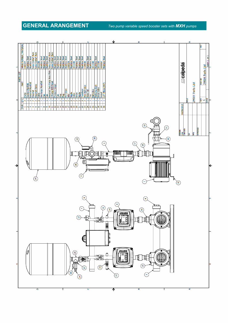
GENERAL ARANGEMENT Two pump variable speed booster sets with MXH pumps
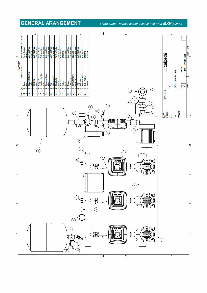
GENERAL ARANGEMENT Three pump variable speed booster sets with MXH pumps

NOTES

Calpeda Limited
Head Office
Unit 6-8, Wedgwood Road Industrial Estate, Bicester, Oxfordshire. OX26 4UL T: 01869 241441 F: 01869 240681 E: [email protected] W: www.calpeda.co.uk
UK Technical and Training Centre
Grove House, Friarwood Lane, Pontefract, West Yorkshire. WF8 1DY T: 01869 241441 F: 01977 709485
E: [email protected] W: www.calpeda.co.uk