committee.tta.or.kr Web viewADSLAsymmetric Digital Subscriber Line (note that the xDSL MEs include...
918
T T A S t a n d a r d 정정정정정정정정(정정정정) TTAE.IT-G.984.4/R1 정정정: 2014정 xx정 xx 정 정정정정 정정 정정정정(GPON): ONT 정정 정 정정 정정정정정 정정 Gigabit-capable Passive Optical Networks (GPON): ONT management and control interface specification TTAE.IT.G.984.4/R1 I
Transcript of committee.tta.or.kr Web viewADSLAsymmetric Digital Subscriber Line (note that the xDSL MEs include...

T T A S t a n d a r d
정보통신단체표준(영문표준)
TTAE.IT-G.984.4/R1 개정일: 2014 년 xx 월 xx 일
기가비트 수동 광통신망(GPON):
ONT 관리 및 제어 인터페이스 규격
Gigabit-capable Passive Optical
Networks (GPON): ONT
management and control interface
specification
TTAE.IT.G.984.4/R1I

정보통신단체표준(영문표준)
TTAE.IT-G.984.4/R1 제정일: 2014 년 xx 월 xx 일
기가비트 수동 광통신망(GPON):ONT 관리 및 제어 인터페이스 규격
Gigabit-capable Passive Optical Networks (GPON):
ONT management and control interface specification
본 문서에 대한 저작권은 TTA 에 있으며, TTA 와 사전 협의 없이 이 문서의 전체 또는 일부를
상업적 목적으로 복제 또는 배포해서는 안 됩니다.
Copyright Telecommunications Technology Association 2014. All Rights Reserved.ⓒ
TTAE.IT.G.984.4/R1II

서 문
1. 표준의 목적
본 표준은 ‘ITU-T G.984.4 Amendment 2 와 Amendment 3’ 표준을 원문 그대로 준용한
것으로, 본 표준의 목적은 여러 장비 업체의 OLT 와 ONT 간 상호 호환 운용 관리를 위해
GPON 시스템에 적용되는 ONT 관리 및 제어 인터페이스 규격(OMCI)을 규정한다. OMCI 는
ONT 의 형상 관리, 장애 관리, 그리고 여러 서비스와 GPON 시스템 운용을 위한 성능 관리에
대한 내용을 정의한다.
2. 주요 내용 요약
본 표준은 GPON 시스템의 ONT 관리 및 제어 인터페이스(OMCI) 규격을 제공한다. OLT 와
ONT 사이의 정보 교환의 모델이 되는 프로토콜 비 종속 MIB(Management Information Base)의 관리 객체(entity)를 규정하고, 부가적으로 OMCC(ONT management and control channel), 프로토콜, 그리고 상세 메시지를 다룬다.
3. 표준 적용 산업 분야 및 산업에 미치는 영향
본 표준은 시간분할다중화 방식의 수동 광통신망 중의 하나인 GPON 기술의 표준을 통해
국내 기가비트 수동광통신망 구축의 토대를 마련한다.
4. 참조 표준(권고)
4.1 국외 표준(권고)
- ITU-T G.984.4, ‘Gigabit-capable passive Optical Networks (GPON): ONT management and control interface specification’, 2008.03.
- ITU-T G.984.4 Amendment 1, ‘Gigabit-capable passive Optical Networks (GPON): ONT management and control interface specification’, 2009.06.
TTAE.IT.G.984.4/R1III

- ITU-T G.984.4 Amendment 2, ‘Gigabit-capable passive Optical Networks (GPON): ONT management and control interface specification’, 2009.11.
- ITU-T G.984.4 Amendment 3, ‘Gigabit-capable passive Optical Networks (GPON): ONT management and control interface specification’, 2010.07.
4.2 국내 표준
- TTAE.IT-G.984.4, ‘기가비트 수동 광통신망(GPON): ONT 관리 및 제어 인터페이스
규격’, 2009.12.
5. 참조 표준(권고)과의 비교
5.1 참조 표준(권고)과의 관련성
본 표준은 Amendment 2 (11/2009)와 Amendment 3 (07/2010) 표준 원문이 그대로
준용되었다.
5.2 참조한 표준(권고)과 본 표준의 비교표
TTAE.IT-G984.4 TTAE.IT-G984.4/R1 비고
1. 범위 1. 범위 수정
2. 참고 2. 참고 수정
3. 정의 3. 정의 동일
4. 약어 4. 약어 동일
5. 개념 5. 개념 동일
6. 기준 모델과 상호관계 6. 기준 모델과 상호관계 동일
7. 관리 인터페이스 규격 요구조건 7. 관리 인터페이스 규격 요구조건 수정
8. OMCI 용 프로토콜 비 종속 MIB 8. OMCI 용 프로토콜 비 종속 MIB 수정
9. MIB 설명 9. MIB 설명 수정
10. ONT 관리 및 제어채널
(OMCC)10. ONT 관리 및 제어채널
(OMCC) 동일
11. ONT 관리 및 제어 프로토콜 11. ONT 관리 및 제어 프로토콜 수정
TTAE.IT.G.984.4/R1IV

부록 I. OMCI 공통 메커니즘과
서비스
부록 I. OMCI 공통 메커니즘과
서비스수정
부록 II. OMCI 메시지 모음 부록 II. OMCI 메시지 모음 수정
부록 III. 트래픽 관리 옵션 부록 III. 트래픽 관리 옵션 수정
부록 IV. 비디오 회귀 경로 부록 IV. 비디오 회귀 경로 동일
6. 지적재산권 관련사항
본 표준의 '지적재산권 확약서‘ 제출 현황은 TTA 웹사이트에서 확인할 수 있다.※본 표준을 이용하는 자는 이용함에 있어 지적재산권이 포함되어 있을 수 있으므로, 확인
후 이용한다.※본 표준과 관련하여 접수된 확약서 이외에도 지적재산권이 존재할 수 있다.
7. 시험인증 관련사항
7.1 시험인증 대상 여부
해당사항 없음.
7.2 시험표준 제정 현황
해당사항 없음.
8. 표준의 이력 정보
8.1. 표준의 이력
판수 제정․개정일 제정․개정내역
제 1 판 2009.12.22 제정
TTAE.IT.G.984.4/R1V

TTAE.IT-G.984.4
제 2 판 2014.xx.xx개정
TTAE.IT-G.984.4/R1
8.2. 주요 개정 사항
TTAE.IT-G984.4/R1 개정내용
1. 범위 요약 내용 수정됨
2. 참고 참고문헌 새롭게 추가됨
7. 관리 인터페이스 규격 요구조건 7.3, 7.4 절 수정, 7.5 절 추가됨
8. OMCI 용 프로토콜 비 종속 MIB 테이블 8-1 과 8-2 절 수정됨
9. MIB 설명 9 장이 수정 및 추가됨.
11. ONT 관리 및 제어 프로토콜 ONT 관리 및 제어 프로토콜 관련하여 개정됨.
부록 I. OMCI 공통 메커니즘과
서비스I.1 절이 개정됨
부록 II. OMCI 메시지 모음 II.1 절과 II.2 절이 개정되고 II.3 절이 추가됨
부록 III. 트래픽 관리 옵션III.2, III.3, III.4 절이 개정되고, III.5 절이
추가됨
TTAE.IT.G.984.4/R1VI

Preface
1. Purpose of Standard
This Recommendation specifies the optical network termination management and control interface (OMCI) for the G-PON to enable multi-vendor interoperability between the optical line termination (OLT) and the ONT. The OMCI specification addresses the ONT configuration management, fault management and performance management for G-PON system operation and for several services.
2. Summary of Contents
This Recommendation provides the optical network termination (ONT) management and control interface (OMCI) specification for gigabit-capable passive optical network (G-PON) systems. Firstly, it specifies the managed entities of a protocol-independent management information base (MIB) that models the exchange of information between the optical line termination (OLT) and the optical network termination (ONT). In addition, it covers the ONT management and control channel, protocol and detailed messages.
3. Applicable fields of industry and its effect
This Recommendation of GPON using Time Division Multiple access method will form the basis on constructing Gigabit-capable PON in domestic access networks.
4. Reference Standards (Recommendations)
4.1 International Standards (Recommendations)
- ITU-T G.984.4, ‘Gigabit-capable passive Optical Networks (GPON): ONT management and control interface specification’, 2008.03.
TTAE.IT.G.984.4/R1VII

- ITU-T G.984.4 Amendment 1, ‘Gigabit-capable passive Optical Networks (GPON): ONT management and control interface specification’, 2009.06.
- ITU-T G.984.4 Amendment 2, ‘Gigabit-capable passive Optical Networks (GPON): ONT management and control interface specification’, 2009.11.
- ITU-T G.984.4 Amendment 3, ‘Gigabit-capable passive Optical Networks (GPON): ONT management and control interface specification’, 2010.07.
4.2 Domestic Standards
- TTAE.IT-G.984.4, ‘Gigabit-capable Passive Optical Networks (GPON): ONT management and control interface specification’, 2009.12.
5. Relationship to Reference Standards (Recommendations)
5.1 Relationship of Reference Standards
This standard is based on ITU-T G.984.4 Amendment 2(11/2009) and Amendment 3(07/2010) recommendation.
5.2 Differences between Reference Standard (recommendation) and this standard
TTAE.IT-G984.4 ITU-T G.984.4/R1 Remarks
1. Scope 1. Scope modification
2. References 2. References modification
3. Definitions 3. Definitions equal
4. Abbreviations and acronyms 4. Abbreviations and acronyms equal
5. Conventions 5. Conventions equal
6. Reference model and terms 6. Reference model and terms equal
7. Requirements of the management interface
7. Requirements of the management interface
modification
TTAE.IT.G.984.4/R1VIII

specification specification
8. Protocol-independent MIB for the OMCI
8. Protocol-independent MIB for the OMCI
modification
9. MIB description 9. MIB description modification
10. ONT management and control channel (OMCC)
10. ONT management and control channel (OMCC) equal
11. ONT management and control protocol
11. ONT management and control protocol
modification
Appendix I – OMCI common mechanisms and services
Appendix I – OMCI common mechanisms and services
modification
Appendix II – OMCI message set Appendix II – OMCI message set modification
Appendix III – Traffic management options
Appendix III – Traffic management options
modification
Appendix IV – Video return path Appendix IV – Video return path equal
6. Statement of Intellectual Property Rights
IPRs related to the present document may have been declared to TTA. The information pertaining to these IPRs, if any, is available on the TTA Website.
No guarantee can be given as to the existence of other IPRs not referenced on the TTA website.
And, please make sure to check before applying the standard.
7. Statement of Testing and Certification
7.1. Object of Testing and Certification
None
TTAE.IT.G.984.4/R1IX

7.2. Standards of Testing and Certification
None
8. History of Standard
8.1. Change History
Edition Issued date Outline
The 1st edition 2009.12.22Established
TTAE.IT-G.984.4
The 2nd edition 2014.xx.xxEstablished
TTAE.IT-G.984.4/R1
8.2. Revisions
TTAE.IT-G984.4/R1 Revisions
1. Scope Modification to summary
2. References New reference to the list in clause 2
7. Requirements of the management interface specification
Modification to clause 7.3 and 7.4.
Add to new clause 7.5
8. Protocol-independent MIB for the OMCI Modification to clause 8.1 and 8.2.
9. MIB description
Modification and Revision to clause 9.1, 9.2, 9.3, 9.4, 9.7. 9.8, 9.9, 9.11, 9.12, 9.13 and 9.14.
Replacement of figure in clause 9.8.
11. ONT management and control protocol Revision to clause 11
Appendix I – OMCI common Revision of Appendix I (I.1, I.1.8, I.1.9 and
TTAE.IT.G.984.4/R1X

mechanisms and services I.2.7)
Appendix II – OMCI message setRevision of Appendix II (II.1, II.2)
Addition of new clause II.3 (Extended OMCI message layout)
Appendix III – Traffic management options
Revision of clause III.2, III.3 and III.4.
Addition of new clause III.5
TTAE.IT.G.984.4/R1XI

목 차
1. 범위 ...............................................................................................................1
2. 참고 ...............................................................................................................1
3. 정의 ...............................................................................................................5
4. 약어 ...............................................................................................................6
5. 개념 ...............................................................................................................12
6. 기준 모델과 상호관계...........................................................................................13
7. 관리 인터페이스 규격 요구조건.............................................................................15
8. OMCI 용 프로토콜 비종속 MIB..............................................................................17
9. MIB 설명............................................................................................................59
10. ONT 관리 및 제어 채널(OMCC)..........................................................................516
11. ONT 관리 및 제어 프로토콜................................................................................517
부록 I. OMCI 공통 메커니즘과 서비스........................................................................540
부록 II. OMCI 메시지 모음........................................................................................568
부록 III. 트래픽 관리 옵션.........................................................................................679
TTAE.IT.G.984.4/R1XII

부록 IV. 비디오 회귀 경로.........................................................................................681
참고문헌 ...............................................................................................................689
TTAE.IT.G.984.4/R1XIII

Contents
1. Scope...............................................................................................................1
2. References.......................................................................................................1
3. Definitions........................................................................................................5
4. Abbreviations and acronyms............................................................................6
5. Conventions......................................................................................................12
6. Reference model and terms.............................................................................13
7. Requirements of the management interface specification...............................15
8. Protocol-independent MIB for the OMCI............................................................17
9. MIB description.................................................................................................59
10. ONT management and control channel (OMCC).............................................516
11. ONT management and control protocol.........................................................517
Appendix I. OMCI common mechanisms and services..........................................540
Appendix II. OMCI message set............................................................................568
Appendix III. Traffic management options............................................................679
TTAE.IT.G.984.4/R1XIV

Appendix IV. Video return path............................................................................681
Bibliography.........................................................................................................689
TTAE.IT.G.984.4/R1XV

기가 비트 수동 광통신망(GPON): ONT 관리 및 제어 인터페이스 규격
Gigabit-capable passive optical networks (GPON): ONT management and control interface specification
1 Scope
The description of OMCI has been made generic in [ITU-T G.988], so that it can cover multiple access system technologies, one of which is G-PON. From January 2010, all new enhancements to the OMCI will be described in [ITU-T G.988], and so [ITU-T G.988] will be the latest and best specification.
The point of this amendment is to direct the readers of Recommendation ITU-T G.984.4 to consult [ITU-T G.988] as their primary reference. That said, Recommendation ITU-T G.984.4 remains "in-force" for those features that are not covered in [ITU-T G.988].
The most up-to-date specification for the ONT management and control interface (OMCI) now appears in [ITU-T G.988]. Readers with a continuing interest in OMCI are advised to consult [ITU-T G.988] as their primary reference. For items where Recommendation ITU-T G.984.4 (2008, as amended) and [ITU-T G.988] conflict, [ITU-T G.988] takes precedence. However, for legacy items specified by Recommendation ITU-T G.984.4, where [ITU-T G.988] remains silent, then the Recommendation ITU-T G.984.4 material remains in force. Further, all code points assigned to such legacy definitions remain reserved and are excluded from the code points assignable by [ITU-T G.988]
2 References1
The following ITU-T Recommendations and other references contain provisions which, through reference in this text, constitute provisions of this Recommendation. At the time of publication, the editions indicated were valid. All Recommendations and other references are subject to revision; users of this Recommendation are therefore encouraged to investigate the possibility of applying the most recent edition of the Recommendations and other references listed below. A list of the currently valid ITU-T Recommendations is regularly published. The reference to a document within this Recommendation does not give it, as a stand-alone document, the status of a Recommendation.[ITU-T G.707] Recommendation ITU-T G.707/Y.1322 (2007), Network node interface
for the synchronous digital hierarchy (SDH).
1 References to implementers' guides in the text of this Recommendation do not give them the status of Recommendations.
TTAE.IT.G.984.4/R11

[ITU-T G.711] Recommendation ITU-T G.711 (1988), Pulse code modulation (PCM) of voice frequencies.
[ITU-T G.722.1] Recommendation ITU-T G.722.1 (1999), Coding at 24 and 32 kbit/s for hands-free operation in systems with low frame loss.
[ITU-T G.722.2] Recommendation ITU-T G.722.2 (2003), Wideband coding of speech at around 16 kbit/s using Adaptive Multi-Rate Wideband (AMR-WB).
[ITU-T G.723.1] Recommendation ITU-T G.723.1 (2006), Dual rate speech coder for multimedia communications transmitting at 5.3 and 6.3 kbit/s.
[ITU-T G.726] Recommendation ITU-T G.726 (1990), 40, 32, 24, 16 kbit/s Adaptive Differential Pulse Code Modulation (ADPCM).
[ITU-T G.728] Recommendation ITU-T G.728 (1992), Coding of speech at 16 kbit/s using low-delay code excited linear prediction.
[ITU-T G.729] Recommendation ITU-T G.729 (2007), Coding of speech at 8 kbit/s using conjugate-structure algebraic-code-excited linear prediction (CS-ACELP).
[ITU-T G.784] Recommendation ITU-T G.784 (1999), Synchronous digital hierarchy (SDH) management.
[ITU-T G.983.2] Recommendation ITU-T G.983.2 (2005), ONT management and control interface specification for B-PON.
[ITU-T G.984.2] Recommendation ITU-T G.984.2 (2003), Gigabit-capable Passive Optical Networks (G-PON): Physical Media dependent (PMD) layer specification.
[ITU-T G.984.3] Recommendation ITU-T G.984.3 (2008), Gigabit-capable Passive Optical Networks (G-PON): Transmission convergence layer specification.
[ITU-T G.992.1] Recommendation ITU-T G.992.1 (1999), Asymmetric digital subscriber line (ADSL) transceivers.
[ITU-T G.992.3] Recommendation ITU-T G.992.3 (2005), Asymmetric digital subscriber line transceivers 2 (ADSL2).
[ITU-T G.992.4] Recommendation ITU-T G.992.4 (2002), Splitterless asymmetric digital subscriber line transceivers 2 (splitterless ADSL2).
[ITU-T G.992.5] Recommendation ITU-T G.992.5 (2005), Asymmetric digital subscriber line (ADSL) transceivers – Extended bandwidth ADSL2 (ADSL2plus).
[ITU-T G.993.1] Recommendation ITU-T G.993.1 (2004), Very high speed digital subscriber line transceivers (VDSL).
[ITU-T G.993.2] Recommendation ITU-T G.993.2 (2006), Very high speed digital subscriber line transceivers 2 (VDSL2).
[ITU-T G.994.1] Recommendation ITU-T G.994.1 (2003), Handshake procedures for digital subscriber line (DSL) transceivers.
TTAE.IT.G.984.4/R12

[ITU-T G.997.1] Recommendation ITU-T G.997.1 (2006), Physical layer management for digital subscriber line (DSL) transceivers.
[ITU-T H.248.x] Recommendation ITU-T H.248.x-series (in force), Gateway control protocol.
[ITU-T H.341] Recommendation ITU-T H.341 (1999), Multimedia management information base.
[ITU-T I.363.5] Recommendation ITU-T I.363.5 (1996), B-ISDN ATM adaptation layer specification: Type 5 AAL.
[ITU-T M.3100] Recommendation ITU-T M.3100 (2005), Generic network information model.
[ITU-T T.35] Recommendation ITU-T T.35 (2000), Procedure for the allocation of ITU-T defined codes for non-standard facilities.
[ITU-T T.38] Recommendation ITU-T T.38 (2005), Procedures for real-time Group 3 facsimile communication over IP networks.
[ATIS-0322000] ATIS-0300220.2005, Representation of the Communications Industry Manufacturers, Suppliers, and Related Service Companies for Information Exchange.http://webstore.ansi.org/RecordDetail.aspx?sku=ATIS-0322000.2005
[ANSI T1.PP.413] ANSI T1.PP.413* (2004), Network to Customer Installation Interfaces - Asymmetric Digital Subscriber Line (ADSL) Metallic Interface.http://webstore.ansi.org/RecordDetail.aspx?sku=T1.PP.413-2004
[ETSI 101 270-1] ETSI TS 101 270-1 V1.4.1 (2005), Transmission and Multiplexing (TM); Access transmission systems on metallic access cables; Very high speed Digital Subscriber Line (VDSL); Part 1: Functional requirements.http://webapp.etsi.org/workprogram/Report_WorkItem.asp?WKI_ID=19789
[ETSI 101 388] ETSI TS 101 388 V1.4.1 (2007), Access Terminals Transmission and Multiplexing (ATTM); Access transmission systems on metallic access cables; Asymmetric Digital Subscriber Line (ADSL) – European specific requirements.http://webapp.etsi.org/workprogram/Report_WorkItem.asp?WKI_ID=27082
[IEEE 802] IEEE 802-2001, IEEE Standard for local and metropolitan area networks Overview and Architecture.<http://standards.ieee.org/getieee802/download/802-2001.pdf>
[IEEE 802.1D] IEEE 802.1D-2004, IEEE Standard for local and metropolitan area networks Media access control (MAC) Bridges.http://standards.ieee.org/getieee802/download/802.1D-2004.pdf
[IEEE 802.1Q] IEEE 802.1Q-2005, IEEE Standard for local and metropolitan area networks Virtual Bridged Local Area Networks.http://standards.ieee.org/getieee802/download/802.1Q-2005.pdf
* * T1 standards are maintained since November 2003 by ATIS.TTAE.IT.G.984.4/R13

[IEEE 802.11] IEEE 802.11-2007, IEEE Standard for local and metropolitan area networks Specific requirements Part 11: Wireless LAN Medium Access Control (MAC) and Physical Layer (PHY) Specifications.http://standards.ieee.org/getieee802/802.11.html
[IETF RFC 815] IETF RFC 815 (1982), IP Datagram Reassembly Algorithms.http://www.ietf.org/rfc/rfc0815.txt
[IETF RFC 1349] IETF RFC 1349 (1992), Type of service in the Internet Protocol Suite.http://www.ietf.org/rfc/rfc1349.txt
[IETF RFC 1483] IETF RFC 1483 (1993), Multiprotocol Encapsulation over ATM Adaptation Layer 5.http://www.ietf.org/rfc/rfc1483.txt
[IETF RFC 2096] IETF RFC 2096 (1997), IP Forwarding Table MIB.http://www.ietf.org/rfc/rfc2096.txt?number=2096
[IETF RFC 2617] IETF RFC 2617 (1999), HTTP Authentication: Basic and Digest Access Authentication.http://www.ietf.org/rfc/rfc2617.txt
[IETF RFC 2833] IETF RFC 2833 (2000), RTP Payload for DTMF Digits, Telephony Tones and Telephony Signals.http://www.ietf.org/rfc/rfc2833.txt
[IETF RFC 3551] IETF RFC 3551 (2003), RTP Profile for Audio and Video Conferences with Minimal Control.http://www.ietf.org/rfc/rfc3551.txt
[IETF RFC 4733] IETF RFC 4733 (2006), RTP Payload for DTMF Digits, Telephony Tones, and Telephony Signals.http://www.ietf.org/rfc/rfc4733.txt
[IETF RFC 4734] IETF RFC 4734 (2006), Definition of Events for Modem, Fax, and Text Telephony Signals.http://www.ietf.org/rfc/rfc4734.txt
[DSLF TR-69] DSLF TR-69 (2007), CPE WAN Management Protocol.http://www.broadband-forum.org/technical/download/TR-069.pdf
[MEF8] Metro Ethernet Forum MEF8 (2004), Implementation Agreement for the Emulation of PDH Circuits over Metro Ethernet Networks.http://metroethernetforum.org/PDFs/Standards/MEF8.pdf
[SCTE 55-1] ANSI/SCTE 55-1 (2002), Digital Broadband Delivery System: Out Of Band Transport Part 1: Mode A.http://www.scte.org/documents/pdf/ANSISCTE5512002DVS178.pdf
[SCTE 55-2] ANSI/SCTE 55-2 (2002), Digital Broadband Delivery System: Out Of Band Transport Part 2: Mode B.http://www.scte.org/documents/pdf/ANSISCTE5522002DVS167.pdf
TTAE.IT.G.984.4/R14

[ITU-T G.704] Recommendation ITU-T G.704 (1998), Synchronous frame structures used at 1544, 6312, 2048, 8448 and 44 736 kbit/s hierarchical levels.
[ITU-T G.826] Recommendation ITU-T G.826 (2002), End-to-end error performance parameters and objectives for international, constant bit-rate digital paths and connections.
[ITU-T G.984.6] Recommendation ITU-T G.984.6 (2008), Gigabit-capable passive optical networks (GPON): Reach extension.
[IEEE 1588] IEEE 1588-2008, IEEE Standard for a Precision Clock Synchronization Protocol for Networked Measurement and Control Systems.
[ITU-T G.986] Recommendation ITU-T G.986 (2010), 1 Gbit/s point-to-point Ethernet-based optical access system.
[ITU-T G.988] Recommendation ITU-T G.988 (2010), ONU management and control interface (OMCI) specification.
3 Definitions
This Recommendation defines the following terms:
3.1 downstream: Downstream is a traffic flow from OLT to ONT.
3.2 optical network termination (ONT): A single subscriber device that terminates any one of the distributed (leaf) endpoints of an ODN, implements a PON protocol, and adapts PON PDUs to subscriber service interfaces. An ONT is a special case of an ONU.
3.3 optical network unit (ONU): A generic term denoting a device that terminates any one of the distributed (leaf) endpoints of an ODN, implements a PON protocol, and adapts PON PDUs to subscriber service interfaces. In some contexts, an ONU implies a multiple subscriber device.
NOTE – This Recommendation uses the term ONT to refer to either configuration unless a distinction is necessary.
3.4 upstream: The upstream is a traffic flow from ONT to OLT.
3.5 shaping and policing: A shaper causes a flow of input packets to conform to a given PIR/PBS by controlling the release rate/burst size of output packets. This typically results in queuing delay; packets may be dropped if there is a queue overflow because the input rate or burst size is too great.
A policer causes a flow of input packets to conform to a given PIR/PBS by immediately dropping packets that exceed PIR/PBS. This typically results in packet loss; packets may be further marked as drop eligible if they exceed CIR/CBS.
TTAE.IT.G.984.4/R15

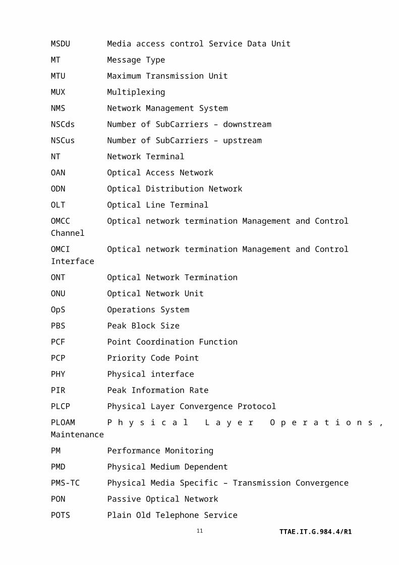
4 Abbreviations and acronyms
This Recommendation uses the following abbreviations and acronyms:
AAL Asynchronous transfer mode Adaptation Layer
ACL Access Control List
ADSL Asymmetric Digital Subscriber Line (note that the xDSL MEs include the G.992 family as well as G.993.2 VDSL2, but not G.993.1 VDSL)
AES Advanced Encryption Standard
AIS Alarm Indication Signal
AK Acknowledgement
AN Access Node
ANI Access Node Interface
AP Access Point
AR Acknowledge Request
ARC Alarm Reporting Control
ARP Address Resolution Protocol
ASCII American Standard Code for Information Interchange
ATM Asynchronous Transfer Mode
ATU-C Asymmetric digital subscriber line Transceiver Unit, Central office end
ATU-R Asymmetric digital subscriber line Transceiver Unit, Remote terminal end
AVC Attribute Value Change
BER Bit Error Rate
BES Block Errored Second
B-PON Broadband Passive Optical Network
BSS Basic Service Set
CAS Channel Associated Signalling
CBS Committed Block Size
CCA Clear Channel Assessment
CES Circuit Emulation Service
CFI Canonical Format Indicator
CFP Contention Free Period
TTAE.IT.G.984.4/R16

CID Customer/Caller Identification
CIR Committed Information Rate
CLEI Common Language Equipment Identification
CLP Cell Loss Priority
CNR Carrier-to-Noise Ratio
CPCS-SDU Common Part Convergence Sublayer Service Data Unit
CPCS-UU Common Part Convergence Sublayer User-to-User Indication
CPI Common Part Indicator
CPS Common Part Sublayer
CRC Cyclic Redundancy Check
CSS Controlled Slip Second
CTB Composite Triple Beat
CTP Connection Termination Point
CTS Clear To Send
DB Destination Bit
DBA Dynamic Bandwidth Assignment
DCF Distributed Coordination Function
DEMUX De-multiplexing
DHCP Dynamic Host Configuration Protocol
DMT Discrete Multitone
DSL Digital Subscriber Line
DSSS Direct-Sequence Spread Spectrum
DTIM Delivery Traffic Indication Message
EMF ElectroMagnetic Field
ES Errored Second
ESS Extended Service Set
FDL Facility Data Link
FEC Forward Error Correction
FHSS Frequency-Hopping Spread Spectrum
FTTB Fibre to the Building
TTAE.IT.G.984.4/R17

FTTBusiness Fibre to the Business
FTTC Fibre to the Curb
FTTCab Fibre to the Cabinet
FTTH Fibre to the Home
GAL Gigabit-capable encapsulation method Adaptation Layer
GEM Gigabit-capable Passive Optical Network Encapsulation Method
G-PON Gigabit-capable Passive Optical Network
GTC Gigabit-capable Passive Optical Network Transmission Convergence
HEC Header Error Correction
HN Home Network
HOL Head of the Line
IBSS Independent Basic Service Set
ICMP Internet Control Message Protocol
ICV Integrity Check Value
ID Identifier
IF Interface
IGMP Internet Group Management Protocol
IP Internet Protocol
IR InfraRed
ISDN Integrated Services Digital Network
IW Interworking
LAN Local Area Network
LBO Line Buildout
LCT Local Craft Terminal
LIM Line Interface Module
LME Sublayer Management Entity
LMI Layer Management Indication
LMIG Layer Management Indication Generation
LMIR Layer Management Indication Receiving
LOS Loss of Signal
TTAE.IT.G.984.4/R18

LSB Least Significant Bit
LT Line Terminal
MAC Media Access Control
MCM Multiple Carrier Modulation
ME Managed Entity
MIB Management Information Base
MLT Mechanized Loop Testing
MMPDU Media access control Management Protocol Data Unit
MoCA Multimedia over Coax Alliance
MPDU Media access control Protocol Data Unit
MSB Most Significant Bit
MSDU Media access control Service Data Unit
MT Message Type
MTU Maximum Transmission Unit
MUX Multiplexing
NMS Network Management System
NSCds Number of SubCarriers – downstream
NSCus Number of SubCarriers – upstream
NT Network Terminal
OAN Optical Access Network
ODN Optical Distribution Network
OLT Optical Line Terminal
OMCC Optical network termination Management and Control Channel
OMCI Optical network termination Management and Control Interface
ONT Optical Network Termination
ONU Optical Network Unit
OpS Operations System
PBS Peak Block Size
PCF Point Coordination Function
PCP Priority Code Point
TTAE.IT.G.984.4/R19

PHY Physical interface
PIR Peak Information Rate
PLCP Physical Layer Convergence Protocol
PLOAM Physical Layer Operations, Administration and Maintenance
PM Performance Monitoring
PMD Physical Medium Dependent
PMS-TC Physical Media Specific – Transmission Convergence
PON Passive Optical Network
POTS Plain Old Telephone Service
PPTP Physical Path Termination Point
PSD Power Spectral Density
PSN Packet Switched Network
PVC Permanent Virtual Circuit
QoS Quality of Service
R'/S' Reach extender interface to optical trunk line
RAD Rate Adaptation Downshift
RDI Remote Defect Indication
RE Reach Extender
RF Radio Frequency
RFI Radio Frequency Interference
RM Resource Management
RTCP Real-time Transport Control Protocol
RTP Real Time Protocol
RTS Request To Send
S'/R' Reach extender interface to optical distribution network
SAR Segmentation And Reassembly
SCM Single Carrier Modulation
SES Severely Errored Second
SIFS Short Interframe Space
SIP Session Initiation Protocol
TTAE.IT.G.984.4/R110
SME Station Management Entity
SN Service Node
SNI Service Node Interface
SNR Signal-to-Noise Ratio
SRA Seamless Rate Adaptation
SSCS Service Specific Convergence Sublayer
STA Station
TC Transmission Convergence
TCA Threshold Crossing Alert
TCI Tag Control Information
T-CONT Transmission Container
TCP Transmission Control Protocol
TDM Time Division Multiplex
TE Terminal Equipment
TOS Type of Service
TP Termination Point
TU Time Unit
TU Tributary Unit
UAS UnAvailable Second
UDP User Datagram Protocol
UNI User Network Interface
UPC Usage Parameter Control
VBR Variable Bit Rate
VC Virtual Circuit
VC Virtual Container (synchronous digital hierarchy)
VCC Virtual Circuit Connection
VCI Virtual Circuit Identifier
VDSL Very high speed Digital Subscriber Line (note that G.993.2 VDSL2 is managed under the xDSL family of MEs)
VID Virtual Local Area Network Identifier
TTAE.IT.G.984.4/R111

VLAN Virtual Local Area Network
VoIP Voice over Internet Protocol
VP Virtual Path
VPC Virtual Path Connection
VPI Virtual Path Identifier
VRP Video Return Path
VTU-O Very high speed Digital Subscriber Line Transceiver Unit, Optical network termination end
VTU-O Very high speed Digital Subscriber Line Transceiver Unit, Optical network termination end
WEP Wired Equivalent Privacy
WRR Weighted Round Robin
xDSL x Digital Subscriber Line
xTU-C x digital subscriber line Transceiver Unit at the Central office end (in the case of PON, the ONT), used as a generic term referring to both the ATU-C of Recommendations ITU-T G.992.x-series and the VTU-O of Recommendation ITU-T G.993.2.
xTU-R x digital subscriber line Transceiver Unit at the Remote end (subscriber premises), used as a generic term referring to both the ATU-R of Recommendations ITU-T G.992.x-series and the VTU-R of Recommendation ITU-T G.993.2.
5 Conventions
In all bit vectors indicated in this Recommendation, the rightmost bit is bit 1. This represents the least significant bit, while bit 8 represents the most significant bit within a byte. If the bit vector is made up of more than one byte, then the numbering starts from the least significant byte onwards.
In all attribute descriptions that refer to the Boolean values "true" and "false," true is coded as 0x01 in hexadecimal and false is coded as 0.
In all attribute descriptions that refer to spaces, the value 0x20 must be used for the entire size of the attribute.
"ASCII string" is a sequence of ASCII encoded characters, terminated by the NULL character (0x00). If a string occupies the entire allocated size of an attribute, the terminating null is not required.
TTAE.IT.G.984.4/R112

6 Reference model and terms
6.1 OMCI in Recommendation ITU-T G.984.1
The network architecture reference model for G-PON is described in [b-ITU-T G.984.1] and shown in Figure 6.1-1. The G-PON fits various access network architectures, e.g., FTTH, FTTB/C and FTTCab.
The OMCI specification fits into the overall [b-ITU-T G.984.1] model for an access network system as illustrated in Figure 6.1-1. The dotted line shows a path for OMCI signals between an OLT and ONT.
Figure 6.1-1 Reference model
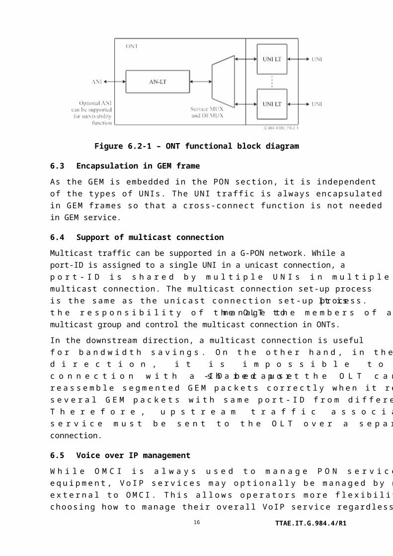
6.2 ONT functions
As shown in Figure 6.2-1, the functions of the ONT are:
a) access network line termination function (AN-LT);
b) user network interface line termination function (UNI-LT), noting that in the fibre to the business case the UNIs from one ONT may belong to different users;
c) service multiplexing and de-multiplexing function (service MUX and DEMUX).
TTAE.IT.G.984.4/R113

Figure 6.2-1 – ONT functional block diagram
6.3 Encapsulation in GEM frame
As the GEM is embedded in the PON section, it is independent of the types of UNIs. The UNI traffic is always encapsulated in GEM frames so that a cross-connect function is not needed in GEM service.
6.4 Support of multicast connection
Multicast traffic can be supported in a G-PON network. While a port-ID is assigned to a single UNI in a unicast connection, a port-ID is shared by multiple UNIs in multiple ONTs in a multicast connection. The multicast connection set-up process is the same as the unicast connection set-up process. It is the responsibility of the OLT to manage the members of a multicast group and control the multicast connection in ONTs.
In the downstream direction, a multicast connection is useful for bandwidth savings. On the other hand, in the upstream direction, it is impossible to support the multicast connection with a shared port-ID because the OLT cannot reassemble segmented GEM packets correctly when it receives several GEM packets with same port-ID from different ONTs. Therefore, upstream traffic associated with a multicast service must be sent to the OLT over a separate unicast connection.
6.5 Voice over IP management
While OMCI is always used to manage PON services and ONT equipment, VoIP services may optionally be managed by means external to OMCI. This allows operators more flexibility in choosing how to manage their overall VoIP service regardless of the access technology involved. VoIP service on an ONT may be managed via one of two paths:
1) OMCI path – OMCI has full view and control of all VoIP service attributes.
2) IP path – OMCI is only used to configure attributes that allow non-OMCI based control of VoIP service attributes.
Specifically, if the OMCI path is used to manage a VoIP service, all of the managed entities defined here may be read and/or written.
TTAE.IT.G.984.4/R1
14

If the IP path is used to manage a SIP VoIP service, only the following MEs may be read and/or written with respect to the VoIP service (all other MEs are unaffected, of course):
• IP host config data;
• IP host PM history data;
• VoIP config data;
• PPTP POTS UNI;
• Call control PM history data;
• RTP PM history data;
• SIP call initiation PM history data;
• SIP agent PM history data;
• SIP config portal;
• VoIP line status.
If the IP path is used to manage a H.248 VoIP service, only the following MEs may be read and/or written with respect to the VoIP service (all other MEs are unaffected, of course):
• IP host config data;
• IP host PM history data;
• VoIP config data;
• PPTP POTS UNI;
• Call control PM history data;
• RTP PM history data;
• MGC PM history data;
• H.248 config portal;
• VoIP line status.
7 Requirements of the management interface specification
The OMCI is used by the OLT to control an ONT. This protocol allows the OLT to:
a) establish and release connections across the ONT;
b) manage the UNIs at the ONT;
c) request configuration information and performance statistics;
d) autonomously inform the system operator of events such as link failures.
The OMCI protocol runs across a GEM connection between the OLT controller and the ONT controller that is established at ONT initialization (note that the option of using an ATM connection for OMCI is deprecated). The OMCI protocol is asymmetric: the controller in the
TTAE.IT.G.984.4/R115
OLT is the master and the one in the ONT is the slave. A single OLT controller using multiple instances of the protocol over separate control channels may control multiple ONTs.
The ONT management and control interface requirements given in this Recommendation are needed to manage the ONT in the following areas:
a) configuration management;
b) fault management;
c) performance management;
d) security management.
7.1 Configuration management
Configuration management provides functions to exercise control over, identify, collect data from and provide data to the ONT. This involves the following:
a) configuration of equipment;
b) configuration of the UNIs;
c) configuration of the GEM port network CTPs;
d) configuration of interworking termination points;
e) configuration of the OAM flows;
f) configuration of the physical ports;
g) configuration of GAL profiles;
h) configuration of service profiles;
i) configuration of traffic descriptors;
j) configuration of AAL profile, in a limited sense.
All ONTs should support GEM transport of user traffic, and the ATM transport mode is deprecated. There is only one connection model for GEM transport, which is the simple point-to-point transfer of user data via a GEM connection across the PON. GEM interworking always occurs in the OLT and the ONT, and GEM never extends beyond the PON link.
In the special case where the ONT supports an ATM UNI (ADSL is the notable example), the ATM connection from the customer must be terminated by the ONT. In this case, the OMCI also supports the required configuration methods to manage this function.
7.2 Fault management
The ONT supports limited fault management only. Most of the operations are limited to failure indication. The OMCI supports failure reporting on many managed entities that are described throughout clause 9. An alarm table is defined for each of these entities.
TTAE.IT.G.984.4/R116

To avoid erratic floods of alarm messages, it is common to filter, or soak, defects such as facility impairments before declaring them as alarms, and to soak defect clearing before retiring the alarm. The declaration soak time is typically 2.5±0.5 seconds, while the retirement soak time is typically 10.5±0.5 seconds. Which alarms are to be soaked, and what the soak intervals should be, are regarded as vendor-specific choices. Interoperability considerations, however, require that alarms be soaked at exactly one of the OLT or ONT, and this Recommendation specifies that they be soaked at the ONT.
7.3 Performance management
The ONT has only limited performance monitoring. The OMCI supports performance monitoring using a subset of managed entities that are described throughout clause 9. These managed entities can be identified by the words "performance monitoring history data" or "extended PM" in their names.
Note that all performance monitoring related managed entities are created at the request of the OLT.
All history data shall be maintained in the OLT.
7.4 Security management
[ITU-T G.984.3] specifies some mechanisms from the viewpoint of security. That includes the downstream data encryption of the ONT. The ONT2-G managed entity can select the downstream encryption algorithm from a list that presently includes only AES.
OMCI also supports a mechanism to allow mutual authentication of OLT and ONT and subsequent secure communication of encryption keys.
7.5 PON protection
This Recommendation supports the protection function. The type C protection configuration that is defined in [b-ITU-T G.984.1] is considered in this Recommendation. As the switching behaviour for PON protection will be done in the TC layer, this Recommendation defines a managed entity to specify the protection capability.
8 Protocol-independent MIB for the OMCI
The OMCI should be defined to allow vendors to offer modular, incremental capabilities to meet different levels of customer needs. This Recommendation defines a protocol necessary to support capabilities identified by [ITU-T G.984.2] and [ITU-T G.984.3]. It is important for interoperability, yet it allows for optional components and future extensions.
A protocol-independent MIB is used to describe the exchange of information across the OMCI. It forms the basis from which protocol-specific models are defined. This MIB has as much commonality as possible with the related generic MIB as defined in other
TTAE.IT.G.984.4/R117

ITU-T Recommendations. It is intended to make the OMCI relatively simple while maintaining consistency with the MIB used by the interface between the network-element manager and the OLT.
8.1 Managed entities
The protocol-independent MIB presented in this Recommendation is defined in terms of managed entities. The managed entities are abstract representations of resources and services in an ONT.
This Recommendation uses three levels for indicating the degree of compliance necessary for specific functions and managed entities associated with the OMCI specification:
• Requirement (R): Entities necessary for operational compatibility.
• Conditional requirements (CR): Entities necessary when the specified optional function is implemented.
• Option (O): Entities that may be useful and required by an operator but that are not necessary for operational compatibility.
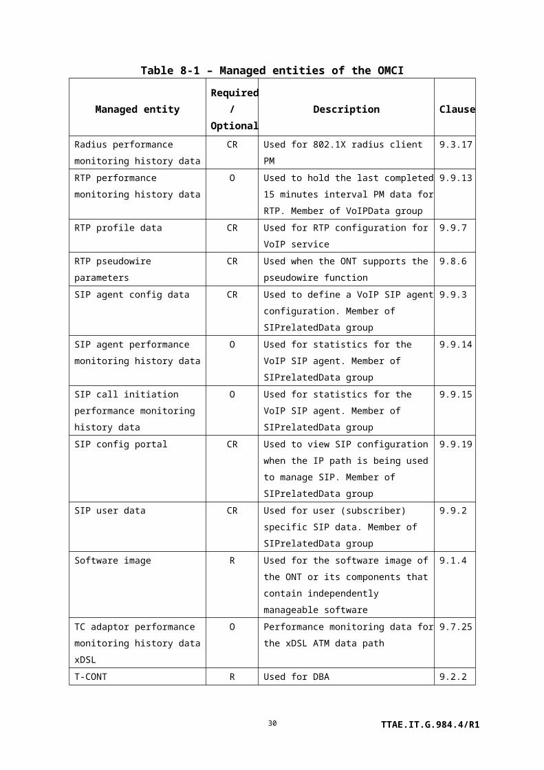
The possible managed entities are listed in Table 8-1. This table also shows the clause within this Recommendation that defines each ME.
Table 8-1 – Managed entities of the OMCI
Managed entityRequired
/Optional
Description Clause
802.11 general purpose object CR Used for 802.11 interface supported by the
ONT
9.6.4
802.11 MAC and PHY operation
and antenna data
CR Used for 802.11 interface supported by the
ONT
9.6.5
802.11 performance monitoring
history data
O Used for 802.11 interface supported by the
ONT
9.6.7
802.11 PHY FHSS DSSS IR
tables
CR Used for 802.11 interface supported by the
ONT
9.6.6
802.11 station management data 1 CR Used for 802.11 interface supported by the
ONT
9.6.2
802.11 station management data 2 CR Used for 802.11 interface supported by the
ONT
9.6.3
802.1p mapper service profile CR Used for 802.1p priority Ethernet UNI 9.3.10
AAL 5 performance monitoring
history data
CR Used for DSL ATM mode interworking 9.13.6
AAL 5 profile CR Used for DSL ATM mode interworking 9.13.5
TTAE.IT.G.984.4/R118

Table 8-1 – Managed entities of the OMCI
Managed entityRequired
/Optional
Description Clause
ANI-G R Used for ANI management 9.2.1
ARP configuration data CR Used for IP port supported by the ONT 9.4.11
ARP service profile CR Used for IP port supported by the ONT 9.4.10
Attribute CR Used when OMCI self-description is
supported
9.12.10
Authentication security method O Used for the user id/password configuration
to associate an IP session between the client
and destination server
9.12.4
Call control performance
monitoring history data
O Used for call control performance
monitoring history. Member of VoIPData
group
9.9.12
Cardholder CR Used for a circuit pack plug-in slot. Can also
represent a virtual cardholder to distinguish
types of ports in an integrated ONT
9.1.5
CES physical interface
performance monitoring history
data
O Used for CES interface performance
monitoring
9.8.4
CES service profile-G CR Used for CES services supported by the
ONT
9.8.3
Circuit pack CR Used for a plug-in circuit pack module. Can
also represent a virtual circuit pack to
distinguish types of ports in an integrated
ONT
9.1.6
Dot1 rate limiter CR Provides for limiting and policing upstream
traffic
9.3.18
Dot1ag CFM stack O Supports 802.1ag configuration fault
management
9.3.25
Dot1ag chassis-management info O Supports 802.1ag configuration fault
management
9.3.26
Dot1ag default MD level O Supports 802.1ag configuration fault
management
9.3.21
Dot1ag maintenance association O Supports 802.1ag configuration fault
management
9.3.20
TTAE.IT.G.984.4/R119

Table 8-1 – Managed entities of the OMCI
Managed entityRequired
/Optional
Description Clause
Dot1ag maintenance domain O Supports 802.1ag configuration fault
management
9.3.19
Dot1ag MEP O Supports 802.1ag configuration fault
management
9.3.22
Dot1ag MEP CCM database O Supports 802.1ag configuration fault
management
9.3.24
Dot1ag MEP status O Supports 802.1ag configuration fault
management
9.3.23
Dot1X configuration profile CR Used for 802.1X control 9.3.15
Dot1X performance monitoring
history data
CR Used for 802.1X control 9.3.16
Dot1X port extension package CR Used for 802.1X control 9.3.14
Enhanced security control CR Supports mutual authentication between
OLT and ONT
9.13.11
Equipment extension package O Used for additional attributes that may be
associated with an ONT or cardholder
9.1.9
Equipment protection profile CR Defines equipment protection groups 9.1.11
Ethernet flow termination point CR Used when the ONT supports the
pseudowire function over layer 2
9.8.9
Ethernet performance monitoring
history data
O Used for Ethernet interface performance
monitoring
9.5.2
Ethernet performance monitoring
history data 2
O Used for Ethernet performance monitoring 9.5.3
Ethernet performance monitoring
history data 3
O Used for Ethernet performance monitoring
(RMON)
9.5.4
Extended VLAN tagging
operation configuration data
CR Contains configuration parameters for
enhanced VLAN operations, including
adding, removing and changing multiple tags
9.3.13
FEC performance monitoring
history data
O Performance monitoring data for FEC on an
ANI-G
9.2.11
GAL Ethernet performance
monitoring history data
O Used when GAL Ethernet layer performance
monitoring is supported
9.2.8
GAL Ethernet profile O Used when the ONT supports GAL Ethernet 9.2.7
TTAE.IT.G.984.4/R120
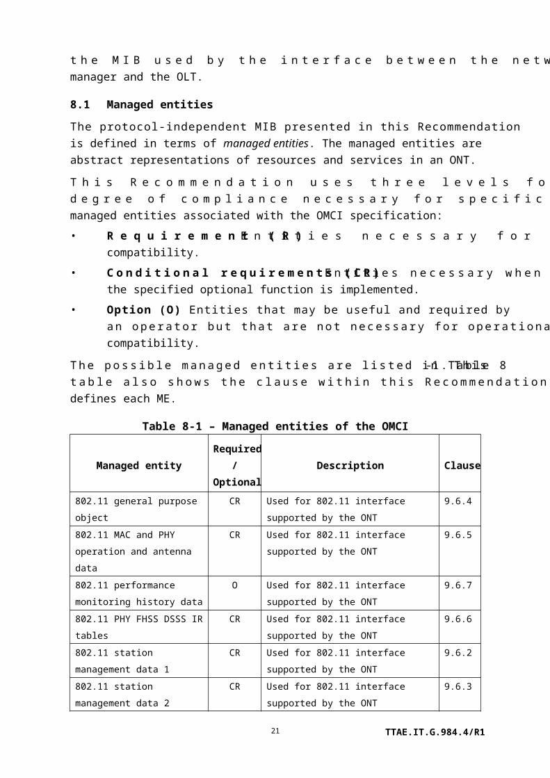
Table 8-1 – Managed entities of the OMCI
Managed entityRequired
/Optional
Description Clause
GAL TDM performance
monitoring history data
O Used when GAL TDM layer performance
monitoring is supported
9.2.10
GAL TDM profile O Used when the ONT supports GAL TDM 9.2.9
GEM interworking termination
point
CR Used for non-ATM UNIs and GEM-based
connections
9.2.4
GEM port network CTP CR Used for GEM port termination 9.2.3
GEM port performance
monitoring history data
O Used for GEM port performance monitoring 9.2.6
GEM traffic descriptor CR Used for GEM-based connections 9.11.3
General purpose buffer O Used to return large blocks of data; structure
defined with each specific application
9.12.12
ICMP performance monitoring
history data 1
O Used for ICMP performance monitoring 9.4.8
ICMP performance monitoring
history data 2
O Used for ICMP performance monitoring 9.4.9
Interworking VCC termination
point
CR Used for DSL ATM mode interworking 9.13.4
IP host config data CR Used to define the Internet protocol service
that may be used with a MAC bridge port.
Member of IPHostData group
9.4.12
IP host performance monitoring
history data
O Used to hold PM counters and alarms for the
IP host. Member of IPHostData group
9.4.13
IP port configuration data CR Used for IP port supported by the ONT 9.4.3
IP route table CR Used for IP router supported by the ONT 9.4.4
IP router configuration data CR Used for IP router supported by the ONT 9.4.2
IP router performance monitoring
history data 1
O Used for IP router performance monitoring 9.4.6
IP router performance monitoring
history data 2
O Used for IP router performance monitoring 9.4.7
IP router service profile CR Used for IP router supported by the ONT 9.4.1
IP static routes CR Used for IP router supported by the ONT 9.4.5
Large string CR Used to hold a character string larger than
25 bytes and up to 375 bytes
9.12.5
TTAE.IT.G.984.4/R121

Table 8-1 – Managed entities of the OMCI
Managed entityRequired
/Optional
Description Clause
Logical N x 64 kbit/s sub-port
connection termination point
CR Used as logical interface for structured CES 9.8.2
MAC bridge configuration data CR Used for MAC bridge supported by the ONT 9.3.2
MAC bridge performance
monitoring history data
O Used for MAC bridge performance
monitoring
9.3.3
MAC bridge port bridge table
data
CR Used for MAC bridge supported by the ONT 9.3.8
MAC bridge port configuration
data
CR Used to organize and record data associated
with a bridge port
9.3.4
MAC bridge port designation data CR Used for MAC bridge supported by the ONT 9.3.5
MAC bridge port filter preassign
table
O Used for Ethernet type filtering 9.3.7
MAC bridge port filter table data CR Used for MAC bridge supported by the ONT 9.3.6
MAC bridge port performance
monitoring history data
O Used for MAC bridge port performance
monitoring
9.3.9
MAC bridge service profile CR Used for MAC bridge supported by the ONT 9.3.1
Managed entity CR Used when OMCI self-description is
supported
9.12.9
MGC config data CR Used for configuration data associated with
an MGC client. Member of H248relatedData
group
9.9.16
MGC config portal CR Used to view H.248 configuration when the
IP path is being used to manage H.248.
Member of H248relatedData group
9.9.20
MGC performance monitoring
history data
O Used for run-time attributes and statistics
associated with an active MGC client.
Member of H248relatedData group
9.9.17
MPLS pseudowire termination
point
CR Supports TDM pseudowires over MPLS 9.8.14
MoCA Ethernet performance
monitoring history data
O Performance monitoring data for the
Ethernet layer on the MoCA interface
9.10.2
MoCA interface performance
monitoring history data
O Performance monitoring data for the
physical layer on the MoCA interface
9.10.3
TTAE.IT.G.984.4/R122

Table 8-1 – Managed entities of the OMCI
Managed entityRequired
/Optional
Description Clause
Multicast GEM interworking
termination point
CR Used to manage multicasting support for
GEM connection
9.2.5
Multicast operations profile CR Used to manage multicast at the ONT 9.3.27
Multicast subscriber config info CR Used to manage multicast at the ONT 9.3.28
Multicast subscriber monitor O Used to manage multicast at the ONT 9.3.29
Network address CR Used to bind a network address (URI, IP
address) to its associated security method.
Member of IPHostData group
9.12.3
Network dial plan table O Used to support network-defined dial plans.
Member of VoIPData group
9.9.10
Octet string O Allows for strings of up to 375 arbitrary
octet values
9.12.11
ONT-E CR Defines the top-level ONT entity for G.986
systems
9.1.13
OLT-G O Used for OLT identification for
interoperability facilitation
9.12.2
OMCI CR Used when OMCI self-description is
supported
9.12.8
ONT data R Used for OMCI MIB management 9.1.3
ONT power shedding CR Used to control the power shedding service 9.1.7
ONT remote debug CR Used to allow remote debugging of an ONT 9.1.12
ONT2-G R Used for ONT equipment management 9.1.2
ONT-G R Used for ONT equipment management 9.1.1
Physical path termination point
802.11 UNI
CR Used for 802.11 interface supported by the
ONT
9.6.1
Physical path termination point
CES UNI
CR Used for physical path termination point at
the CES UNI
9.8.1
Physical path termination point
Ethernet UNI
CR Used for physical path termination point at
the Ethernet UNI
9.5.1
Physical path termination point
ISDN UNI
O Used for ISDN port supported by the ONT 9.9.21
Physical path termination point
LCT UNI
O Used for local craft terminal port 9.13.3
TTAE.IT.G.984.4/R123

Table 8-1 – Managed entities of the OMCI
Managed entityRequired
/Optional
Description Clause
Physical path termination point
MoCA UNI
CR Used for the physical path termination point
for MoCA interfaces
9.10.1
Physical path termination point
POTS UNI
CR Used for physical path trail termination point
at the POTS UNI
9.9.1
Physical path termination point
video ANI
O Used for optical RF video input port 9.13.2
Physical path termination point
video UNI
O Used for electrical video output port 9.13.1
Physical path termination point
xDSL UNI part 1
CR Used for the physical path termination point
at an xDSL CO modem
9.7.1
Physical path termination point
xDSL UNI part 2
CR Used for the physical path termination point
at an xDSL CO modem
9.7.2
Port mapping package-G O Used to map heterogeneous ports to an
equipment entity
9.1.8
Priority queue-G CR Used for ONTs that support priority queues
to multiplex ATM or GEM traffic flows
9.11.1
Protection data CR Used for PON protection 9.1.10
Pseudowire maintenance profile CR Used when the ONT supports the
pseudowire function
9.8.7
Pseudowire performance
monitoring history data
CR Used when the ONT supports the
pseudowire function
9.8.8
Pseudowire termination point CR Used when the ONT supports the
pseudowire function
9.8.5
Radius performance monitoring
history data
CR Used for 802.1X radius client PM 9.3.17
RTP performance monitoring
history data
O Used to hold the last completed 15 minutes
interval PM data for RTP. Member of
VoIPData group
9.9.13
RTP profile data CR Used for RTP configuration for VoIP service 9.9.7
RTP pseudowire parameters CR Used when the ONT supports the
pseudowire function
9.8.6
SIP agent config data CR Used to define a VoIP SIP agent
configuration. Member of SIPrelatedData
group
9.9.3
TTAE.IT.G.984.4/R124

Table 8-1 – Managed entities of the OMCI
Managed entityRequired
/Optional
Description Clause
SIP agent performance
monitoring history data
O Used for statistics for the VoIP SIP agent.
Member of SIPrelatedData group
9.9.14
SIP call initiation performance
monitoring history data
O Used for statistics for the VoIP SIP agent.
Member of SIPrelatedData group
9.9.15
SIP config portal CR Used to view SIP configuration when the IP
path is being used to manage SIP. Member
of SIPrelatedData group
9.9.19
SIP user data CR Used for user (subscriber) specific SIP data.
Member of SIPrelatedData group
9.9.2
Software image R Used for the software image of the ONT or
its components that contain independently
manageable software
9.1.4
TC adaptor performance
monitoring history data xDSL
O Performance monitoring data for the xDSL
ATM data path
9.7.25
T-CONT R Used for DBA 9.2.2
TCP/UDP config data CR Used for the TCP or UDP configuration for a
TCP/UDP service. Member of IPHostData
group
9.4.14
Threshold data 1 CR Used for PM threshold values 9.12.6
Threshold data 2 CR Used for PM threshold values 9.12.7
Traffic descriptor CR Used to specify traffic management
parameters
9.11.3
Traffic scheduler-G CR Used for DBA 9.11.2
TU CTP CR Organizes data that describes the VC path
adaptation processing functions of the ONT
for SDH services
9.8.10
TU performance monitoring
history data
O Performance monitoring data collected as a
result of TU connection monitoring
9.8.11
UNI-G CR Used for user network interface for GEM
service
9.12.1
VDSL2 line configuration
extensions
CR Contains xDSL attributes unique to VDSL2
(G.993.2)
9.7.6
TTAE.IT.G.984.4/R125

Table 8-1 – Managed entities of the OMCI
Managed entityRequired
/Optional
Description Clause
VDSL2 line inventory and status
data part 1
CR Contains additional test and status attributes
for xDSL lines, specifically, extensions for
VDSL2
9.7.16
VDSL2 line inventory and status
data part 2
CR Contains additional test and status attributes
for xDSL lines, specifically, extensions for
VDSL2
9.7.17
VDSL2 line inventory and status
data part 3
CR Contains additional test and status attributes
for xDSL lines, specifically, extensions for
VDSL2
9.7.18
Video return path performance
monitoring history data
CR Used for video return path management 9.13.8
Video return path service profile CR Used for video return path management 9.13.7
Virtual Ethernet interface point CR Defines a data plane handoff to other
management domains such as TR-69 or
SNMP
9.5.5
VLAN tagging filter data O Used for VLAN tagging 9.3.11
VLAN tagging operation
configuration data
O Used for VLAN tagging 9.3.12
Voice service profile CR Used for voice 9.9.6
VoIP application service profile O Used for VoIP calling feature services.
Member of VoIPData group
9.9.8
VoIP config data CR Used to discover VoIP signalling protocols
supported and select a VoIP signalling to
use. Also used to select a VoIP configuration
method. Member of VoIPData group
9.9.18
VoIP feature access codes O Used to define feature access codes for a
POTS port. Member of VoIPData group
9.9.9
VoIP line status O Used for VoIP line status that relates to a
POTS port. Member of VoIPData group
9.9.11
VoIP media profile CR Used to define codec and other media
selection criteria. Member of VoIPData
group
9.9.5
VoIP voice CTP CR Used for VoIP voice channel termination
point. Member of VoIPData group
9.9.4
TTAE.IT.G.984.4/R126

Table 8-1 – Managed entities of the OMCI
Managed entityRequired
/Optional
Description Clause
VP network CTP-G CR Used for DSL ATM mode interworking 9.13.9
VP performance monitoring
history data
CR Used for DSL ATM mode interworking 9.13.10
xDSL channel configuration
profile
CR Contains configuration for an xDSL channel 9.7.7
xDSL channel downstream status
data
CR Contains status on a downstream xDSL
channel
9.7.19
xDSL channel upstream status
data
CR Contains status on an upstream xDSL
channel
9.7.20
xDSL downstream RFI bands
profile
CR Contains information on the downstream
RFI bands
9.7.11
xDSL line configuration profile
part 1
CR Contains line parameters for an xDSL line 9.7.3
xDSL line configuration profile
part 2
CR Contains line parameters for an xDSL line 9.7.4
xDSL line configuration profile
part 3
CR Contains line parameters for an xDSL line 9.7.5
xDSL line inventory and status
data part 1
CR Contains inventory and status information on
an xDSL line
9.7.12
xDSL line inventory and status
data part 2
CR Contains inventory and status information on
an xDSL line
9.7.13
xDSL line inventory and status
data part 3
CR Contains additional test and status attributes
for xDSL lines
9.7.14
xDSL line inventory and status
data part 4
CR Contains additional test and status attributes
for xDSL lines
9.7.15
xDSL PSD mask profile CR Contains PSD masking information 9.7.10
xDSL subcarrier masking
downstream profile
CR Contains masking information for the
downstream subcarriers
9.7.8
xDSL subcarrier masking
upstream profile
CR Contains masking information for the
upstream subcarriers
9.7.9
xDSL xTU-C channel
performance monitoring history
data
O Performance monitoring data for an xDSL
xTU-C channel
9.7.23
TTAE.IT.G.984.4/R127

Table 8-1 – Managed entities of the OMCI
Managed entityRequired
/Optional
Description Clause
xDSL xTU-C performance
monitoring history data
O Performance monitoring data for an xDSL
xTU-C modem path
9.7.21
xDSL xTU-R channel
performance monitoring history
data
O Performance monitoring data for an xDSL
xTU-R channel
9.7.24
xDSL xTU-R performance
monitoring history data
O Performance monitoring data for an xDSL
xTU-R modem path
9.7.22
RE ANI-G CR Used for mid-span PON reach extender
ANI
9.14.1
Physical path termination point
RE UNI
CR Used for mid-span PON reach extender
UNI
9.14.2
RE upstream amplifier CR Used for mid-span PON reach extender
upstream optical amplifier
9.14.3
RE downstream amplifier CR Used for mid-span PON reach extender
downstream optical amplifier
9.14.4
RE config portal CR Used for non-OMCI configuration
method on mid-span PON reach
extenders
9.14.5
RE common amplifier
parameters
CR Used for monitoring and maintenance of
PON reach extender optical amplifiers
9.14.6
File transfer controller O Used to control out-of-band file transfers 9.12.13
CES physical interface
performance monitoring
history data 2
O Used for PM of DS1, E1 and similar
CESs
9.8.12
CES physical interface
performance monitoring
history data 3
O Used for PM of DS1, E1 and similar
CESs
9.8.13
Ethernet frame performance
monitoring history data
upstream
O Used for PM of upstream Ethernet flows
on a bridge port
9.3.30
TTAE.IT.G.984.4/R128

Table 8-1 – Managed entities of the OMCI
Managed entityRequired
/Optional
Description Clause
Ethernet frame performance
monitoring history data
downstream
O Used for PM of downstream Ethernet
flows on a bridge port
9.3.31
VDSL2 line configuration
extensions 2
O Used to configure additional VDSL2
parameters
9.7.26
xDSL impulse noise monitor
performance monitoring
history data
O Used for impulse noise monitoring PM 9.7.27
xDSL line inventory and status
data part 5
CR Additional xDSL test parameters for
G.992.3, G.992.5 Annex C
9.7.28
xDSL line inventory and status
data part 6
CR Additional xDSL test parameters for
G.992.3, G.992.5 Annex C
9.7.29
xDSL line inventory and status
data part 7
CR Additional xDSL test parameters for
G.992.3, G.992.5 Annex C
9.7.30
8.2 Managed entity relation diagrams
This clause shows the relationships between managed entities. Figure 8.2-1 gives the legend of symbols used in these diagrams. The name of the managed entity, sometimes abbreviated for ease of documentation, appears in each box, with the clause in which it is defined shown in the lower right corner.
TTAE.IT.G.984.4/R129
Entity created by ONU
Entity created by OLT
Entity A has explicit pointer to entity B
Entity A has implicit ID relationship to entity B (ME IDs are equal)
1
0..X
1
1
There can be 0..X instances of A related to B
There is a 1 to 1 relationship of A to B
OR Only one of the options is active for any one instance
A performance monitoring (PM) entity, always created by the OLT, optionallyassociated with an instance of thresholddata 1 and 2
Managed entity A
9.xx.xx
Managed entity A
9.xx.xx
Managed entity B
9.xx.xx
Managed entity B
9.xx.xx
xx PM history data
9.xx.xx
xx PM history data
9.xx.xx
Managed entity B
9.xx.xx
Managed entity B
9.xx.xx
Managed entity B
9.xx.xx
Managed entity B
9.xx.xx
Managed entity B
9.xx.xx
Managed entity B
9.xx.xx
Managed entity B
9.xx.xx
Managed entity B
9.xx.xx
Managed entity A
9.xx.xx
Managed entity A
9.xx.xx
Managed entity A
9.xx.xx
Managed entity A
9.xx.xx
Managed entity A
9.xx.xx
Managed entity A
9.xx.xx
Managed entity A
9.xx.xx
Managed entity A
9.xx.xx
1
Figure 8.2-1 Legend for managed entity relation diagrams
TTAE.IT.G.984.4/R130

8.2.1 ONT common functions
1
1
1
1..255
1
0..1
1 1..127 1..127 1
11
0..256
1
1
2
0,2
1
0..256
10..n
0..1
1
0..n OR10..n
1
0..256
0..256
OR
0..n
0..n0..n
1
1
11
1
0..1
0..n0..1
1
10..1
0..1
ONT-G
9.1.1
ONT-G
9.1.1
ONT2-G
9.1.2
ONT2-G
9.1.2
ONT data
9.1.3
ONT data
9.1.3
Software image
9.1.4
Software image
9.1.4
CardholderCardholder
Circuit packCircuit pack
ANIANI
Cardholder
9.1.5
Cardholder
9.1.5
Port mapping package-G
9.1.8
Port mapping package-G
9.1.8
Traffic scheduler-G
9.11.2
Traffic scheduler-G
9.11.2
Traffic descriptor
Traffic descriptor
Circuit pack
9.1.6
Circuit pack
9.1.6
Equipment extension package 9.1.9
Equipment extension package 9.1.9
Priority queue-G (up)
9.11.1
Priority queue-G (up)
9.11.1
Priority queue-G (down) 9.11.1
Priority queue-G (down) 9.11.1
PPTPxx
UNI
UNI-G
9.12.1
UNI-G
9.12.1
GEM port netwk CTP
9.2.3
GEM port netwk CTP
9.2.3
T-CONT
9.2.2
T-CONT
9.2.2
GEM port PM history GEM port PM history
1
Figure 8.2.1-1 ONT core
TTAE.IT.G.984.4/R131

1
0..256
OR1
0..256
0..256
1
0..256
OR
0..n
1
0..256
0..2560..1
OR
0..n
0..n
1
0..n
1
1..255
1
1..255
Working side Protecting side
When protection is activated,
pointers to T-CONTs and
schedulers are mapped from
working side to protecting side
Protectedtraffic
Traffic scheduler-G
9.11.2
Traffic scheduler-G
9.11.2
Traffic scheduler-G
9.11.2
Traffic scheduler-G
9.11.2
T-CONT
9.2.2
T-CONT
9.2.2
T-CONT
9.2.2
T-CONT
9.2.2
Circuit pack
9.1.6
Circuit pack
9.1.6
GEM port netwk CTP
9.2.3
GEM port netwk CTP
9.2.3
Priority queue-G (up)
9.11.1
Priority queue-G (up)
9.11.1
ANI-G
9.2.1
ANI-G
9.2.1
ANI-G
9.2.1
ANI-G
9.2.1
Protection data
9.1.10
Protection data
9.1.10
Circuit pack
9.1.6
Circuit pack
9.1.6
Figure 8.2.1-2 1+1 PON protection
TTAE.IT.G.984.4/R132

0..1
OR
0..n
1
0..n
Extratraffic
0..n
1
0..256
OR
0..n
1
0..256
0..2560..1
OR
0..n
0..n
1
0..n
1
1..255
Working side
When protection is activated,
pointers to T-CONTs and
schedulers are mapped from
working side to protecting side
Protectedtraffic
Traffic scheduler-G
9.11.2
Traffic scheduler-G
9.11.2
T-CONT
9.2.2
T-CONT
9.2.2
Circuit pack
9.1.6
Circuit pack
9.1.6
GEM port netwk CTP
9.2.3
GEM port netwk CTP
9.2.3
Priority queue-G (up)
9.11.1
Priority queue-G (up)
9.11.1
ANI-G
9.2.1
ANI-G
9.2.1
Protection data
9.1.10
Protection data
9.1.10
1
0..256
OR1
0..256
0..256
1
1..255
Protecting side
Traffic scheduler-G
9.11.2
Traffic scheduler-G
9.11.2
T-CONT
9.2.2
T-CONT
9.2.2
ANI-G
9.2.1
ANI-G
9.2.1
Priority queue-G (up)
9.11.1
Priority queue-G (up)
9.11.1
GEM port netwk CTP
9.2.3
GEM port netwk CTP
9.2.3
Circuit pack
9.1.6
Circuit pack
9.1.6
Figure 8.2.1-3 1:1 PON protection
8.2.2 Layer 2 functions
OMCI supports two major layer 2 traffic mapping models: MAC bridging and "802.1p mapping." MAC bridging is described in [IEEE 802.1D] and [IEEE 802.1Q]. The bridge described in Figure 8.2.2-1 below has many features, and can be used to direct traffic based on MAC address (that is, true bridging) or on VLAN characteristics (using the VLAN filter feature). The mapping function describes the steering of traffic from one UNI-side entity to 1-8 ANI-side Port-IDs, as shown in Figure 8.2.2-2 below. The mapper is equivalent to a MAC bridge with VLAN filters that only operate on the priority bits of the VLAN tags.
TTAE.IT.G.984.4/R133

0..p1
11
0..1
1
1
1
1
0..11
1
0..n
0..1
1
11
0..1
0..w
0..m
1
0..1 1
0..1 1
11
Any ME to which VLAN tagging can be assigned
0..11
1
UNI-G
9.12.1
UNI-G
9.12.1
PPTP xx UNIPPTP
xx UNI
MAC bridge config data
9.3.2
MAC bridge config data
9.3.2
MB port filter preassign table 9.3.7
MB port filter preassign table 9.3.7
MAC bridge port filter table 9.3.6
MAC bridge port filter table 9.3.6
MAC bridge port bridge table 9.3.8
MAC bridge port bridge table 9.3.8
MB port designation data 9.3.5
MB port designation data 9.3.5
Extended VLAN tag op 9.3.13
Extended VLAN tag op 9.3.13
VLAN tag op config data 9.3.12
VLAN tag op config data 9.3.12
GEM interworking TP 9.2.4
GEM interworking TP 9.2.4
GEM port network CTP 9.2.3
GEM port network CTP 9.2.3
GAL Ethernet profile 9.2.7
GAL Ethernet profile 9.2.7
VLAN tagging filter data 9.3.11
VLAN tagging filter data 9.3.11
MAC bridge port config data 9.3.4
MAC bridge port config data 9.3.4
MAC bridge port config data 9.3.4
MAC bridge port config data 9.3.4
MAC bridge service profile 9.3.1
MAC bridge service profile 9.3.1
MAC bridge PM
9.3.3
MAC bridge PM
9.3.3
GAL Ethernet PM 9.2.8
GAL Ethernet PM 9.2.8
11
MB port PM
9.3.9
MB port PM
9.3.9
11
Enet frame PM, up/dn
9.3.30-31
Enet frame PM, up/dn
9.3.30-31
1
1
Dot1 rate limiter
9.3.18
Dot1 rate limiter
9.3.18
1
0..1
Figure 8.2.2-1 MAC bridged LAN
NOTE 1 – A bridge port may be associated with any IEEE 802.3 UNI, such as Ethernet or xDSL, or
another 802.3 function such as an IP host config data ME.
TTAE.IT.G.984.4/R134

1
0..8
Any ME to which VLAN tagging can be assigned
1
1
0..n
0..1 1GEM interworking TP 9.2.4
GEM interworking TP 9.2.4
GEM port network CTP 9.2.3
GEM port network CTP 9.2.3
GAL Ethernet profile 9.2.7
GAL Ethernet profile 9.2.7
GAL Ethernet PM 9.2.8
GAL Ethernet PM 9.2.8
Extended VLAN tag op 9.3.13
Extended VLAN tag op 9.3.13
VLAN tag op config data 9.3.12
VLAN tag op config data 9.3.12
1 1UNI-G
9.12.1
UNI-G
9.12.1
PPTP xx
UNI
PPTP xx
UNI
802.1p mapper svc profile 9.3.10
802.1p mapper svc profile 9.3.10
0..1
8
Dot1 rate limiter
9.3.18
Dot1 rate limiter
9.3.18
10..1
Figure 8.2.2-2 802.1p mapper
NOTE 2 – A mapper service profile may be associated with any IEEE 802.3 UNI, such as Ethernet or
xDSL, or another 802.3 function such as an IP host config data ME.
The two basic layer 2 services can be used in various combinations to achieve different overall connectivities. There are three major functional styles of layer 2 connectivity, illustrated in Figures 8.2.2-3 to 8.2.2-5:
• N:1 bridging, where a bridge is used to serve multiple UNI ports from a single ANI service;
• 1:M mapping, where a mapper is used to serve a single UNI with multiple ANI connections, based on 802.1p priorities;
• 1:P filtering, where a bridge with filters is used to serve a single UNI with multiple ANI connections, based on some VLAN information other than 802.1p priorities.
Given these three basic possibilities, there are also four more complex combinations as well, illustrated in Figures 8.2.2-6 to 8.2.2-9. It is strongly encouraged that these applications be utilized before other, more exotic styles of usage.
TTAE.IT.G.984.4/R135

N
1
1
1
1 1
111
1
1
1
11
11
MAC bridge service profile 9.3.1
MAC bridge service profile 9.3.1
MAC bridge port config data 9.3.4
MAC bridge port config data 9.3.4
MAC bridge port config data 9.3.4
MAC bridge port config data 9.3.4
MAC bridge port config data 9.3.4
MAC bridge port config data 9.3.4
GEM interworking TP 9.2.4
GEM interworking TP 9.2.4
(Extended) VLAN tag op 9.3.12-13
(Extended) VLAN tag op 9.3.12-13
(Extended) VLAN tag op 9.3.12-13
(Extended) VLAN tag op 9.3.12-13
PPTPxx
UNI
PPTPxx
UNI
Dot1 rate limiter
9.3.18
Dot1 rate limiter
9.3.18
1
0..1
Figure 8.2.2-3 Illustration of N:1 bridging
TTAE.IT.G.984.4/R136

1
11
1
1
GEM port network CTP1
GEM port network CTP
1
M
1
11
1
11
GEM interworking TP 9.2.4
GEM interworking TP 9.2.4
GEM interworking TP 9.2.4
GEM interworking TP 9.2.4
(Extended) VLAN tag op 9.3.12-13
(Extended) VLAN tag op 9.3.12-13
PPTPxx
UNI
802.1p mapper svc profile 9.3.10
802.1p mapper svc profile 9.3.10
Dot1 rate limiter
9.3.18
Dot1 rate limiter
9.3.18
1
0..1
Figure 8.2.2-4 Illustration of 1:M mapping
TTAE.IT.G.984.4/R137

1
1
1
1
11
11
1
1
11
1
1
1
1
1
1
1
1
P
11
MAC bridge service profile 9.3.1
MAC bridge service profile 9.3.1
MAC bridge port config data 9.3.4
MAC bridge port config data 9.3.4
MAC bridge port config data 9.3.4
MAC bridge port config data 9.3.4
MAC bridge port config data 9.3.4
MAC bridge port config data 9.3.4
GEM interworking TP 9.2.4
GEM interworking TP 9.2.4
GEM interworking TP 9.2.4
GEM interworking TP 9.2.4
(Extended) VLAN tag op 9.3.12-13
(Extended) VLAN tag op 9.3.12-13
PPTPxx
UNI
VLAN tagging filter data 9.3.11
VLAN tagging filter data 9.3.11
VLAN tagging filter data 9.3.11
VLAN tagging filter data 9.3.11
VLAN tagging filter data 9.3.11
VLAN tagging filter data 9.3.11
Dot1 rate limiter
9.3.18
Dot1 rate limiter
9.3.181
0..1
Figure 8.2.2-5 Illustration of 1:P filtering
TTAE.IT.G.984.4/R138

N
1
1
1
1
1
1
1
1
GEM port network CTP1
GEM port network CTP
1
M
1
11
1
1
1
1
11
11
MAC bridge service profile 9.3.1
MAC bridge service profile 9.3.1
MAC bridge port config data 9.3.4
MAC bridge port config data 9.3.4
MAC bridge port config data 9.3.4
MAC bridge port config data 9.3.4
GEM interworking TP 9.2.4
GEM interworking TP 9.2.4
GEM interworking TP 9.2.4
GEM interworking TP 9.2.4
(Extended) VLAN tag op 9.3.12-13
(Extended) VLAN tag op 9.3.12-13
(Extended) VLAN tag op 9.3.12-13
(Extended) VLAN tag op 9.3.12-13
MAC bridge port config data 9.3.4
MAC bridge port config data 9.3.4
PPTPxx
UNI
PPTPxx
UNI
802.1p mapper svc profile 9.3.10
802.1p mapper svc profile 9.3.10
Dot1 rate limiter
9.3.18
Dot1 rate limiter
9.3.18
1
0..1
Figure 8.2.2-6 Illustration of N:M bridge-mapping
TTAE.IT.G.984.4/R139
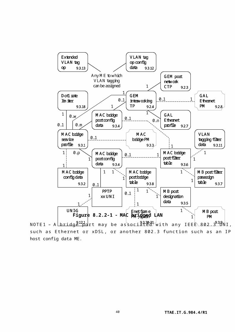
1
1
1
1
11
1
1 1
11
1
GEM port network CTP1
GEM port network CTP
1
M
1
11
1
1
1
GEM port network CTP1
GEM port network CTP
1
M
1
11
11
1 1
P
1
1
11
MAC bridge service profile 9.3.1
MAC bridge service profile 9.3.1
MAC bridge port config data 9.3.4
MAC bridge port config data 9.3.4
GEM interworking TP 9.2.4
GEM interworking TP 9.2.4
GEM interworking TP 9.2.4
GEM interworking TP 9.2.4
GEM interworking TP 9.2.4
GEM interworking TP 9.2.4
GEM interworking TP 9.2.4
GEM interworking TP 9.2.4
(Extended) VLAN tag op 9.3.12-13
(Extended) VLAN tag op 9.3.12-13
PPTPxx
UNI
VLAN tagging filter data 9.3.11
VLAN tagging filter data 9.3.11
VLAN tagging filter data 9.3.11
VLAN tagging filter data 9.3.11
VLAN tagging filter data 9.3.11
VLAN tagging filter data 9.3.11
MAC bridge port config data 9.3.4
MAC bridge port config data 9.3.4
MAC bridge port config data 9.3.4
MAC bridge port config data 9.3.4
802.1p mapper svc profile 9.3.10
802.1p mapper svc profile 9.3.10
802.1p mapper svc profile 9.3.10
802.1p mapper svc profile 9.3.10
Dot1 rate limiter
9.3.18
Dot1 rate limiter
9.3.18
10..1
Figure 8.2.2-7 Illustration of 1:MP map-filtering
TTAE.IT.G.984.4/R140

1
1
1
1
11
11
1
11
1
1
1
1
1
1
1
N
1
1
1
P
11
11
MAC bridge service profile 9.3.1
MAC bridge service profile 9.3.1
MAC bridge port config data 9.3.4
MAC bridge port config data 9.3.4
MAC bridge port config data 9.3.4
MAC bridge port config data 9.3.4
MAC bridge port config data 9.3.4
MAC bridge port config data 9.3.4
MAC bridge port config data 9.3.4
MAC bridge port config data 9.3.4
GEM interworking TP 9.2.4
GEM interworking TP 9.2.4
GEM interworking TP 9.2.4
GEM interworking TP 9.2.4
(Extended) VLAN tag op 9.3.12-13
(Extended) VLAN tag op 9.3.12-13
(Extended) VLAN tag op 9.3.12-13
(Extended) VLAN tag op 9.3.12-13
PPTPxx
UNI
PPTPxx
UNI
VLAN tagging filter data 9.3.11
VLAN tagging filter data 9.3.11
VLAN tagging filter data 9.3.11
VLAN tagging filter data 9.3.11
VLAN tagging filter data 9.3.11
VLAN tagging filter data 9.3.11
Dot1 rate limiter
9.3.18
Dot1 rate limiter
9.3.18 1 0..1
Figure 8.2.2-8 Illustration of N:P bridge-filtering
TTAE.IT.G.984.4/R141

N
1
1
1
1
1
1
1
GEM port network CTP1
GEM port network CTP
1
M
1
11
1
1
1
GEM port network CTP1
GEM port network CTP
1
M
1
11
1
1
11
1
1
1
1
1
1
11
P1
11
11
MAC bridge service profile 9.3.1
MAC bridge service profile 9.3.1
MAC bridge port config data 9.3.4
MAC bridge port config data 9.3.4
MAC bridge port config data 9.3.4
MAC bridge port config data 9.3.4
MAC bridge port config data 9.3.4
MAC bridge port config data 9.3.4
MAC bridge port config data 9.3.4
MAC bridge port config data 9.3.4
GEM interworking TP 9.2.4
GEM interworking TP 9.2.4
GEM interworking TP 9.2.4
GEM interworking TP 9.2.4
GEM interworking TP 9.2.4
GEM interworking TP 9.2.4
GEM interworking TP 9.2.4
GEM interworking TP 9.2.4
(Extended) VLAN tag op 9.3.12-13
(Extended) VLAN tag op 9.3.12-13
(Extended) VLAN tag op 9.3.12-13
(Extended) VLAN tag op 9.3.12-13
PPTPxx
UNI
PPTPxx
UNI
VLAN tagging filter data 9.3.11
VLAN tagging filter data 9.3.11
VLAN tagging filter data 9.3.11
VLAN tagging filter data 9.3.11
VLAN tagging filter data 9.3.11
VLAN tagging filter data 9.3.11
802.1p mapper svc profile 9.3.10
802.1p mapper svc profile 9.3.10
802.1p mapper svc profile 9.3.10
802.1p mapper svc profile 9.3.10
Figure 8.2.2-9 Illustration of N:MP bridge-map-filtering
Figure 8.2.2-10 illustrates the use of the multicast interworking termination point. A bridge is used to multiplex the multiple ANI-side ports into the single (in this case) UNI-side port. It is essential to have a unicast path in parallel to the multicast path, because the unicast path carries the upstream signalling that is required for control of the multicast transmissions. In most scenarios, a unicast path already exists for other user communications.
TTAE.IT.G.984.4/R142

1
1
1
1
11
11
1
1..n1
1
2
11
Ext VLAN tag op
(optional)
1
1
1
1
Note: An extended VLAN tagging operation config data may be associated with the multicast GEM interworking TP or the UNI to specify simple downstream multicast VLAN behaviour.
MAC bridge service profile 9.3.1
MAC bridge service profile 9.3.1
MAC bridge port config data 9.3.4
MAC bridge port config data 9.3.4
MAC bridge port config data 9.3.4
MAC bridge port config data 9.3.4
MAC bridge port config data 9.3.4
MAC bridge port config data 9.3.4
GEM interworking TP 9.2.4
GEM interworking TP 9.2.4
(Extended) VLAN tag op 9.3.12-13
(Extended) VLAN tag op 9.3.12-13
Ext VLAN tag op
(optional)
PPTPxx
UNI
Multicast GEM IW TP
9.2.5
Multicast GEM IW TP
9.2.5
Figure 8.2.2-10 Illustration of multicast service
TTAE.IT.G.984.4/R143
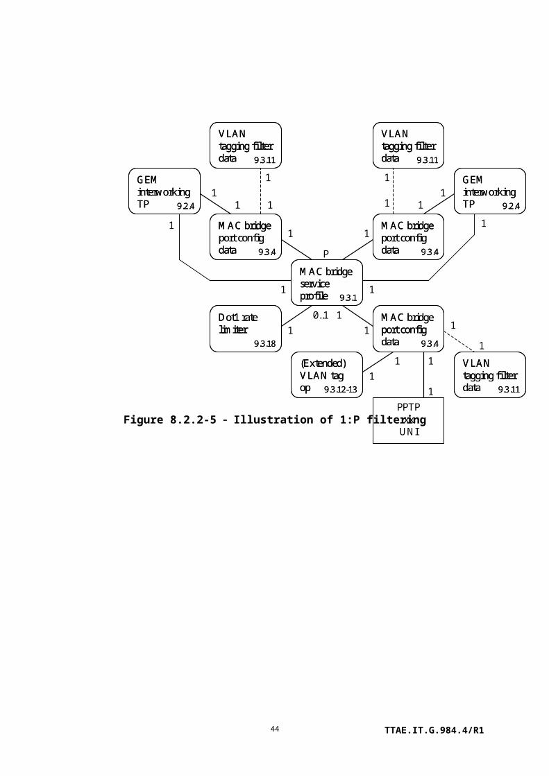
M
1 1
1
1
1
1..n
1
1
1
1
GEM port network CTP
M
Note: Interworking option set to downstream broadcast
MAC bridge service profile 9.3.1
MAC bridge service profile 9.3.1
MAC bridge service profile 9.3.1
MAC bridge service profile 9.3.1
MAC bridge port config data 9.3.4
MAC bridge port config data 9.3.4
MAC bridge port config data 9.3.4
MAC bridge port config data 9.3.4
GEM IW TP (note)
9.2.4
GEM IW TP (note)
9.2.4
VLAN tagging filter data 9.3.11
VLAN tagging filter data 9.3.11
VLAN tagging filter data 9.3.11
VLAN tagging filter data 9.3.11
Figure 8.2.2-11 Illustration of downstream broadcast configuration
Figure 8.2.2-12 Illustration of 802.1ag in MAC bridge model
TTAE.IT.G.984.4/R144

Figure 8.2.2-13 Illustration of 802.1ag in 802.1p mapper model
NOTE 3 – If a mapper is associated with ports of a bridge, the 802.1ag entities should be associated
with the bridge and its ports, rather than with the mapper.
TTAE.IT.G.984.4/R145

8.2.3 Routing
0..p1
0..w
1
0..m1
1
1
1
1 0..1
1
PPTP xx
UNI
0..1
1
1
1
0..1
0..1
1
1
1
1
GEM port network CTP
0..n
0..1 1GEM interworking TP 9.2.4
GEM interworking TP 9.2.4
GAL Ethernet PM 9.2.8
GAL Ethernet PM 9.2.8
IP router PM 1..2
9.4.6, -.7
IP router PM 1..2
9.4.6, -.7
ICMP PM history 1..2
9.4.8, -.9
ICMP PM history 1..2
9.4.8, -.9
GAL Ethernet profile 9.2.7
GAL Ethernet profile 9.2.7
ARP config data
9.4.11
ARP config data
9.4.11
ARP service profile
9.4.10
ARP service profile
9.4.10
IP port config data
9.4.3
IP port config data
9.4.3
IP router service profile 9.4.1
IP router service profile 9.4.1
IP port config data
9.4.3
IP port config data
9.4.3
IP route table
9.4.4
IP route table
9.4.4
IP static routes
9.4.5
IP static routes
9.4.5
IP router config data
9.4.2
IP router config data
9.4.2
Figure 8.2.3-1 IP routing
TTAE.IT.G.984.4/R146

8.2.4 xDSL service
1N
0..256
8 0..n
1
0..p
0..q
0..r
0..s
1..4
1
1
1
1
1
1
10..1
1
0..11..4
1
1
0..1
10..1
1
1
1
1
1
1
1
11
1
From layer 2 ME (802.1p or MAC bridge port configuration data) or VP network CTP-G
UNI-G
9.12.1
UNI-G
9.12.1
PPTP xDSL UNI 1
9.7.1
PPTP xDSL UNI 1
9.7.1
PPTP xDSL UNI 2
9.7.2
PPTP xDSL UNI 2
9.7.2
xDSL line inv & status 1..79.7.12-15, .28-30
xDSL line inv & status 1..79.7.12-15, .28-30
VDSL2 line inv & status 1..3 9.7.16-18
VDSL2 line inv & status 1..3 9.7.16-18
xDSL chan down status
9.7.19
xDSL chan down status
9.7.19
xDSL chan upstr status
9.7.20
xDSL chan upstr status
9.7.20
xDSL down RFI bands profile 9.7.11
xDSL down RFI bands profile 9.7.11
xDSL subcarrier mask dn 9.7.8
xDSL subcarrier mask dn 9.7.8
xDSL subcarrier mask up 9.7.9
xDSL subcarrier mask up 9.7.9
xDSL PSD mask
9.7.10
xDSL PSD mask
9.7.10
xDSL line config 1..3
9.7.3-5
xDSL line config 1..3
9.7.3-5
xDSL chan config profile 9.7.7
xDSL chan config profile 9.7.7
VDSL2 line config ext 1..2 9.7.6, .26
VDSL2 line config ext 1..2 9.7.6, .26
TC adaptor PM history xDSL 9.7.25
TC adaptor PM history xDSL 9.7.25
xTU-C PM history
9.7.21
xTU-C PM history
9.7.21
xTU-C channel PM 9.7.23
xTU-C channel PM 9.7.23
xTU-R PM history
9.7.22
xTU-R PM history
9.7.22
xTU-R channel PM 9.7.24
xTU-R channel PM 9.7.24
Impulse noise PM
9.7.27
Impulse noise PM
9.7.27
1
Figure 8.2.4-1 xDSL
TTAE.IT.G.984.4/R147

0..1
1
0..1
1
0..n
10..1
10..n
PPTP xDSL UNI part 1Note: individual bearer channels accessible via 2 MSBs of PPTP ME id
0..256
1
From layer 2 ME (802.1p mapper or MAC bridge port configuration data)
AAL5 PM history data
9.13.6
AAL5 PM history data
9.13.6
VP PM history data
9.13.10
VP PM history data
9.13.10
AAL5 profile
9.13.5
AAL5 profile
9.13.5
Interworking VCC TP
9.13.4
Interworking VCC TP
9.13.4
VP network CTP-G
9.13.9
VP network CTP-G
9.13.9
Figure 8.2.4-2 ATM interworking for xDSL
8.2.5 802.11 service
1
1
0..1
1
11 1
1
1
2..n20..21
0..11
From layer 2 ME (802.1p mapper or MAC bridge port configuration data)
UNI-G
9.12.1
UNI-G
9.12.1
802.11 PM history data
9.6.7
802.11 PM history data
9.6.7
PPTP802.11 UNI
9.6.1
PPTP802.11 UNI
9.6.1
802.11 station mgt data 1..2
9.6.2-3
802.11 station mgt data 1..2
9.6.2-3
802.11 PHY FHSS DSSS IR tables 9.6.6
802.11 PHY FHSS DSSS IR tables 9.6.6
802.11 MAC PHY ops & antenna 9.6.5
802.11 MAC PHY ops & antenna 9.6.5
802.11 gen purpose ME
9.6.4
802.11 gen purpose ME
9.6.4
Figure 8.2.5-1 802.11 wireless LAN
TTAE.IT.G.984.4/R148

8.2.6 MoCA service
1
1
0..1
1
0..11
0..11
From layer 2 ME (802.1p mapper or MAC bridge port configuration data)
UNI-G
9.12.1
UNI-G
9.12.1
PPTP MoCA UNI
9.10.1
PPTP MoCA UNI
9.10.1
MoCA interface PM 9.10.3
MoCA interface PM 9.10.3
MoCA Ethernet PM 9.10.2
MoCA Ethernet PM 9.10.2
Figure 8.2.6-1 Multimedia over Coax Alliance (MoCA)
8.2.7 Video return path
1
0..1
1
1
GEM port network CTP
0..n
0..1 1
0..1
1
GEM interworking TP 9.2.4
GEM interworking TP 9.2.4
GAL Ethernet PM 9.2.8
GAL Ethernet PM 9.2.8
Video ret path PM
9.13.8
Video ret path PM
9.13.8
GAL Ethernet profile 9.2.7
GAL Ethernet profile 9.2.7
Video return path service profile 9.13.7
Video return path service profile 9.13.7
PPTP video ANI
9.13.2
PPTP video ANI
9.13.2
PPTP video UNI
9.13.1
PPTP video UNI
9.13.1
Cardholder
9.1.5
Cardholder
9.1.5
11
NN
Figure 8.2.7-1 Video return path
TTAE.IT.G.984.4/R149

8.2.8 VoIP service
Note: MEs that require long character strings point to large string MEs. MEs that require a network address point to network address MEs.
0..1 0..1
111
1
0..1 0..11
1
1
11
0..1
UNI-G
9.12.1
UNI-G
9.12.1
VoIP config data
9.9.18
VoIP config data
9.9.18
SIP config portal
9.9.19
SIP config portal
9.9.19
PPTP POTS UNI
9.9.1
PPTP POTS UNI
9.9.1
VoIP line status
9.9.11
VoIP line status
9.9.11
RTP PM history data
9.9.13
RTP PM history data
9.9.13
Call ctrl PM history
9.9.12
Call ctrl PM history
9.9.12
SIP agent PM history
9.9.14
SIP agent PM history
9.9.14
SIP call initiation PM 9.9.15
SIP call initiation PM 9.9.15
Figure 8.2.8-1 IP-path managed SIP VoIP
TTAE.IT.G.984.4/R150

0..1 0..1
1
1
1
0..11
0..1
0..1
11
1
UNI-G
9.12.1
UNI-G
9.12.1
VoIP config data
9.9.18
VoIP config data
9.9.18
PPTP POTS UNI
9.9.1
PPTP POTS UNI
9.9.1
VoIP line status
9.9.11
VoIP line status
9.9.11
RTP PM history data
9.9.13
RTP PM history data
9.9.13
MGC PM history
9.9.17
MGC PM history
9.9.17
MGC config portal
9.9.20
MGC config portal
9.9.20
Call ctrl PM history
9.9.12
Call ctrl PM history
9.9.12
Note: MEs that require long character strings point to large string MEs. MEs that require a network address point to network address MEs.
Figure 8.2.8-2 IP path managed ITU-T H.248 VoIP
TTAE.IT.G.984.4/R151

0..11
1
1
0..m
0..m
1
11
0..1
10..1
1
0..m 1
0..m0..1
0..1
0..11
1
11 1
11
0..1
1
1
0..m
10..m1
1
0..1
1
UNI-G
9.12.1
UNI-G
9.12.1
SIP call initiation PM 9.9.15
SIP call initiation PM 9.9.15
SIP agent PM history data 9.9.14
SIP agent PM history data 9.9.14
RTP PM history data
9.9.13
RTP PM history data
9.9.13
PPTP POTS UNI
9.9.1
PPTP POTS UNI
9.9.1
VoIP line status
9.9.11
VoIP line status
9.9.11
VoIP config data
9.9.18
VoIP config data
9.9.18
RTP profile data
9.9.7
RTP profile data
9.9.7
VoIP media profile
9.9.5
VoIP media profile
9.9.5
VoIP voice CTP
9.9.4
VoIP voice CTP
9.9.4
Voice service profile 9.9.6
Voice service profile 9.9.6
Network dial plan table
9.9.10
Network dial plan table
9.9.10
VoIP feature access codes
9.9.9
VoIP feature access codes
9.9.9
SIP agent config data
9.9.3
SIP agent config data
9.9.3
TCP/UDP config data
9.4.14
TCP/UDP config data
9.4.14
VoIP appl service profile 9.9.8
VoIP appl service profile 9.9.8
Authentic’n security method 9.12.4
Authentic’n security method 9.12.4
SIP user data
9.9.2
SIP user data
9.9.2
Call ctrl PM history
9.9.12
Call ctrl PM history
9.9.12
Note: MEs that require long character strings point to large string MEs. MEs that require a network address point to network address MEs.
Figure 8.2.8-3 OMCI managed SIP VoIP
TTAE.IT.G.984.4/R152

1
10..1
0..1
0..11
1
1
0..m
0..m
1
11
0..1
10..1
11
1
1
1
1
0..1
UNI-G
9.12.1
UNI-G
9.12.1
VoIP voice CTP
9.9.4
VoIP voice CTP
9.9.4
VoIP line status
9.9.11
VoIP line status
9.9.11
VoIP media profile
9.9.5
VoIP media profile
9.9.5
Voice service profile 9.9.6
Voice service profile 9.9.6
RTP profile data
9.9.7
RTP profile data
9.9.7
VoIP config data
9.9.18
VoIP config data
9.9.18
RTP PM history data
9.9.13
RTP PM history data
9.9.13
Call control PM
9.9.12
Call control PM
9.9.12
PPTP POTS UNI
9.9.1
PPTP POTS UNI
9.9.1
TCP/UDP config data
9.4.14
TCP/UDP config data
9.4.14
MGC config data
9.9.16
MGC config data
9.9.16
MGC PM history data
9.9.17
MGC PM history data
9.9.17
Note: MEs that require long character strings point to large string MEs. MEs that require a network address point to network address MEs.
Figure 8.2.8-4 OMCI managed ITU-T H.248 VoIP
0..1
0..m
0..1
1
11
Any ME that requires a network address
1
11
From layer 2 ME (802.1p mapper or MAC bridge port configuration data)
Network address
9.12.3
Network address
9.12.3
Authentic’n security method 9.12.4
Authentic’n security method 9.12.4
Large string
9.12.5
Large string
9.12.5
TCP/UDP config data
9.4.14
TCP/UDP config data
9.4.14
IP host PM history data
9.4.13
IP host PM history data
9.4.13
IP host config data
9.4.12
IP host config data
9.4.12
Figure 8.2.8-5 Common IP services
TTAE.IT.G.984.4/R153

8.2.9 Circuit emulation service
OR
1
1
10..1
1
1
11..n
1..n1
1 1
Structured Unstructured
1
1
Over EthernetOver IP
1 1
0..1
1
1
From layer 2 ME (802.1p mapper or MAC bridge port configuration data)
UNI-G
9.12.1
UNI-G
9.12.1
PPTP CES UNI
9.8.1
PPTP CES UNI
9.8.1
TCP/UDP config data
9.4.14
TCP/UDP config data
9.4.14
Pseudowire PM history data 9.8.8
Pseudowire PM history data 9.8.8
Pseudowire mtce profile
9.8.7
Pseudowire mtce profile
9.8.7
Pseudowire termination point 9.8.5
Pseudowire termination point 9.8.5
RTP pseudowire parms 9.8.6
RTP pseudowire parms 9.8.6
Ethernet flow TP
9.8.9
Ethernet flow TP
9.8.9
Logical N x 64 CTP
9.8.2
Logical N x 64 CTP
9.8.2
CES phy PM 1, 2, 3
9.8.4, -.12-13
CES phy PM 1, 2, 3
9.8.4, -.12-13
MPLS PW TP
9.8.14
MPLS PW TP
9.8.14
OR
Over MPLS11
1
1
GEM port network CTP
GEM IW TP
9.2.4
GEM IW TP
9.2.4
OR1
Figure 8.2.9-1 Pseudowire TDM
TTAE.IT.G.984.4/R154
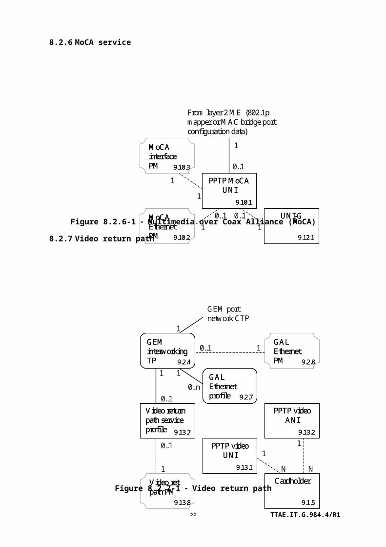
OR
1
0..1
1
11..n
1..n1
1
1 1
Structured Unstructured
11
1
GEM port network CTP
0..1 1
0..1
1
1
UNI-G
9.12.1
UNI-G
9.12.1
GEM interworking TP 9.2.4
GEM interworking TP 9.2.4
PPTP CES UNI
9.8.1
PPTP CES UNI
9.8.1
CES phy PM 1, 2, 3
9.8.4, -.12-13
CES phy PM 1, 2, 3
9.8.4, -.12-13
Logical N x 64 CTP
9.8.2
Logical N x 64 CTP
9.8.2
TU PM history data
9.8.11
TU PM history data
9.8.11
TU CTP
9.8.10
TU CTP
9.8.10
Pseudowire mtce profile
9.8.7
Pseudowire mtce profile
9.8.7
GAL TDM profile
9.2.9
GAL TDM profile
9.2.9
GAL TDM PM history
9.2.10
GAL TDM PM history
9.2.101
n
CES service profile-G
9.8.3
CES service profile-G
9.8.3
11..n
Figure 8.2.9-2 SDH over GEM
8.2.10 Mid-span PON reach extenders
The PON reach extender is modelled as an ONT (the management entity) containing cardholders and circuit packs whose functions are to extend the reach of one or more PONs. The PON reach extender's own management ONT is understood to exist as a member of one of the extended PONs.
Figure 8.2.10-1 – Mid-span PON reach extender core (repeater)
NOTE 1 – In many cases, the RE ANI-G and PPTP RE UNI are implemented on the same circuit
pack. If so, the port mapping package can be used to create the hybrid line card.
TTAE.IT.G.984.4/R155

0..2551
1
1
1
1
RE upstream amplifier
9.14.3
RE upstream amplifier
9.14.3
RE downstr amplifier
9.14.4
RE downstr amplifier
9.14.4
RE common amplifier parms 9.14.6
RE common amplifier parms 9.14.6
RE common amplifier parms 9.14.6
RE common amplifier parms 9.14.6
Figure 8.2.10-2 – Mid-span PON reach extender core (optical amplifier)
NOTE 2 – In many cases, the RE upstream amplifier and RE downstream amplifier are implemented
on the same circuit pack. If so, the port mapping package can be used to create the hybrid line card.
1
11
1
0..2551PPTP
RE UNI9.14.2
PPTP RE UNI
9.14.2
RE ANI-G
9.14.1
RE ANI-G
9.14.1
RE common amplifier parms 9.14.6
RE common amplifier parms 9.14.6
RE upstream amplifier
9.14.3
RE upstream amplifier
9.14.3
Figure 8.2.10-3 – Mid-span PON reach extender core (hybrid)
1
1
1
1
0..2551PPTP
RE UNI9.14.2
PPTP RE UNI
9.14.2
RE ANI-G
9.14.1
RE ANI-G
9.14.1
RE common amplifier parms 9.14.6
RE common amplifier parms 9.14.6
RE downstr amplifier
9.14.4
RE downstr amplifier
9.14.4
Figure 8.2.10-4 – Mid-span PON reach extender core (hybrid)
TTAE.IT.G.984.4/R156

0..m
0..1
1
1
0..1
1
To MAC bridge service per existing in-band management protocol server
RE config portal
9.14.5
RE config portal
9.14.5
IP host config data
9.4.12
IP host config data
9.4.12
MAC bridge port config data 9.3.4
MAC bridge port config data 9.3.4
TCP/UDP config data
9.4.14
TCP/UDP config data
9.4.14
Figure 8.2.10-5 – In-band management for mid-span PON reach extender
8.2.11 Point-to-point Gigabit-Ethernet-fed ONT
1 M
1
1
ONT-E
9.1.13
ONT-E
9.1.13
ONT data
9.1.3
ONT data
9.1.3
PPTP Ethernet UNI
9.5.1
PPTP Ethernet UNI
9.5.1
Figure 8.2.11-1 – P2P GbE-fed ONT
9 MIB description
This clause defines all ONT managed entities (MEs) of interest to G-PON. Code points for a number of managed entities are permanently reserved for B-PON legacy implementations; these managed entities remain available for use in G-PON if needed, but their definitions appear only in [ITU-T G.983.2], rather than below. In a few cases, managed entities that were specifically defined for G-PON have proven to be of little interest. As with B-PON MEs, their code points are permanently reserved for backward compatibility, but in the interest of brevity, their definitions have been omitted from this revision of this Recommendation.
Managed entity (ME) descriptions include:
a) The purpose of the entity.
b) The relationships that the entity supports with other managed entities.
c) The attributes of the entity.
TTAE.IT.G.984.4/R157

d) The management operations (actions) that may be performed on the entity. Actions such as create, delete, get, get next, set and get current data are generic and are merely listed in the description of a given ME. Other actions are described in more detail.
e) The notifications generated by the managed entity. These may be attribute value changes (AVCs), alarms or performance monitoring threshold crossing alerts. Tables define each of these three classes as needed for each ME type.
These clauses are organized as follows:
9.1 Equipment management
9.2 ANI management
9.3 Layer 2 data services
9.4 Layer 3 data services
9.5 Ethernet services
9.6 802.11 services
9.7 xDSL services
9.8 TDM services
9.9 Voice services
9.10 MoCA
9.11 Traffic management
9.12 General purpose MEs
9.13 Miscellaneous services
9.14 Mid-span PON reach extender
A managed entity can be instantiated by the ONT autonomously or on explicit request of the OLT via a create command. Attributes of a managed entity for which no create action exists (i.e., a managed entity that is auto-instantiated by the ONT) can be (R), (W) or (R, W).
On the other hand, attributes of a managed entity for which a create action exists (i.e., a managed entity that is instantiated on explicit request by the OLT) can be either (R), (W), (R, W), (R, Set-by-create), (W, Set-by-create) or (R, W, Set-by-create). Where appropriate, this Recommendation specifies a default value, to be assigned to the attribute on instantiation of the managed entity.
The following explains each case in more detail:
(R): On instantiation of the managed entity, either autonomously or on request of the OLT via a create action, the ONT sets the attribute to a default value or to a value that reflects a current state or measurement. The OLT can only read the value of the attribute. In case of an autonomous attribute value
TTAE.IT.G.984.4/R158

change, the ONT may send an attribute value change notification (AVC) to the OLT.
(W): On instantiation of the managed entity, either autonomously or on request of the OLT via a create action, an initial value may or may not be specified. The OLT can only write the value of the attribute. Such an attribute never triggers an AVC notification to the OLT.
(R, W): On instantiation of the managed entity, either autonomously or on request of the OLT via a create action, the ONT sets the attribute to a default value. The OLT can both read and write the value of the attribute. In case of an autonomous attribute value change, the ONT may send an AVC notification to the OLT.
(R, Set-by-create): On instantiation of the managed entity, by necessity on request of the OLT via a create action, the ONT sets the attribute to the value specified in the create command. Subsequently, the OLT cannot change the value of the attribute. This combination is used mostly for managed entity IDs, but occasionally for attributes that cannot meaningfully change after ME creation.
(W, Set-by-create): On instantiation of the managed entity, by necessity on request of the OLT via a create action, the ONT sets the attribute to the value specified in the create command. Subsequently, the OLT can only write the value of the attribute. Such an attribute never triggers an AVC notification to the OLT.
(R, W, Set-by-create): On instantiation of the managed entity, by necessity on request of the OLT via a create action, the ONT sets the attribute to the value specified in the create command. Subsequently, the OLT can both read and write the value of the attribute. In case of an autonomous attribute value change, the ONT may send an AVC notification to the OLT. In a number of cases, it is logically impossible to change (write) the value of an attribute after the ME is created. However, chicken and egg issues can arise when several such MEs point to each other. Allowing such attributes to be set after creation is intended to avoid these issues.
The notifications generated by a managed entity stem from the following events: alarms, attribute value changes (AVCs), threshold crossing alerts (TCAs) and test results.
Alarms, TCAs and failures of autonomous self tests are all reported via alarm messages. The alarm reporting message contains a field of 224 bits, which is mapped to as many as 208 specific alarms by the definition of each managed entity. The last 16 bits are reserved for vendor-specific alarms and are not to be standardized. Alarm bits are numbered from 0 upward. The general schema is illustrated in the following table, where each managed entity
TTAE.IT.G.984.4/R159

definition may specify some of the 208 reserved points for its own alarms. Different ME types can re-use the same code points because the alarm report message includes the ME type (and instance).
Generic alarm bit assignment
Number Alarm Description
0..207 Reserved
208..223 Vendor-specific alarms Not to be standardized
AVCs are reported via attribute value change messages. A managed entity can encompass not more than 16 attributes, exclusive of the ME ID, and the attribute change message contains a bit map of 16 bits that match attributes in order, starting with 1. If a managed entity can generate AVCs, its definition includes an AVC table that matches attributes with their corresponding bit numbers for easy reference. Attributes that do not trigger AVC notifications are shown as N/A, while bit positions for non-existent attributes are shown as reserved.
Test results are reported:
a) via a test result message if the test is invoked by a test command from the OLT; or
b) via an alarm message in the case of failure of an autonomous self test in the start-up phase; or
c) via an autonomous test result message if a test failure is detected autonomously by the ONT.
Details about these messages and their coding appear in Appendix II.
9.1 Equipment management
An ONT may be physically implemented as a single module (integrated ONT) or as a shelf containing plug-in field-replaceable units. The latter construction is technically called an ONU, but this Recommendation often uses the terms interchangeably to refer to either. Except for equipment-specific features, the same criteria pertain to both versions.
An ONU with physical slots automatically instantiates cardholder MEs for each of its slots. A slot can then be populated with a circuit pack. Physical slots are recommended to number from left to right, then from bottom to top.
An integrated ONT may or may not model itself with virtual cardholders and circuit packs. If not, the ONT itself is understood to exist in virtual slot 0, since a number of MEs use the slot id as part of their identifiers.
When subscriber and PON-side physical ports are grouped into real or virtual circuit packs, each of which supports only a single type of interface, the port numbering algorithm is clear. An integrated ONT may choose not to model itself with virtual cardholders, and a complex circuit pack may have ports of several types, for example a PON ANI, a video UNI and a craft
TTAE.IT.G.984.4/R160

port. The port mapping package provides a flexible way to associate port numbers with a heterogeneous assortment of ports.
9.1.1 ONT-G
This managed entity represents the ONT as equipment. The ONT automatically creates an instance of this managed entity. It assigns values to read-only attributes according to data within the ONT itself.
Relationships
All other managed entities in this Recommendation are related directly or indirectly to the ONT-G entity.
Attributes
Managed entity id: This attribute uniquely identifies each instance of this managed entity. There is only one instance, number 0. (R) (mandatory) (2 bytes)
Vendor id: This attribute identifies the vendor of the ONT. It is the same as the four most significant bytes of the ONT serial number as specified in [ITU-T G.984.3]. (R) (mandatory) (4 bytes)
Version: This attribute identifies the version of the ONT as defined by the vendor. The character value "0" indicates that version information is not available or applicable. (R) (mandatory) (14 bytes)
Serial number: The serial number is unique for each ONT. It is defined in [ITU-T G.984.3] and contains the vendor ID and version number. The first four bytes are an ASCII-encoded vendor ID four letter mnemonic. The second four bytes are a binary encoded serial number, under the control of the ONT vendor. (R) (mandatory) (8 bytes)
Traffic management option:
This attribute identifies the upstream traffic management function implemented in the ONT. There are two options:
0 Priority controlled and flexibly scheduled upstream traffic. The traffic scheduler and priority queue mechanism are used for upstream traffic.
1 Rate controlled upstream traffic. The maximum upstream traffic of each individual connection is guaranteed.
2 Priority and rate controlled. The traffic scheduler and priority queue mechanism are used for upstream traffic. The maximum upstream traffic of each individual connection is guaranteed by shaping.
VP/VC cross-connection function option:
This attribute is not used. If it is present, it should be set to 0. (R) (optional) (1 byte)
TTAE.IT.G.984.4/R161

Battery backup: This Boolean attribute specifies whether the ONT/NT supports backup battery monitoring. False disables battery alarm monitoring; true enables battery alarm monitoring. (R, W) (mandatory) (1 byte)
Administrative state:
This attribute locks (1) and unlocks (0) the functions performed by this managed entity. When the administrative state is set to lock, all user functions are blocked, and alarms, TCAs and AVCs for this managed entity and all dependent managed entities are no longer generated. Selection of a default value for this attribute is outside the scope of this Recommendation. (R, W) (mandatory) (1 byte)
Operational state: This attribute reports whether the managed entity is currently capable of performing its function. Valid values are enabled (0) and disabled (1). (R) (optional) (1 byte)
Actions
Get, set
Reboot: Reboot the ONT.
Test: Test the ONT. The test action can be used either to perform equipment diagnostics or to measure parameters such as received optical power, video output level, battery voltage, etc. Extensions to the test and test response messages are defined for these purposes; refer to Appendix II.
Synchronize time: This action synchronizes the start time of all performance monitoring managed entities of the ONT with the reference time of the OLT. All counters of all monitoring managed entities are cleared to 0 and restarted. Also, the value of the interval end time attribute of the monitoring managed entities is set to 0 and restarted. See clause I.1.9 for further discussion of PM.
ONT survival time: This attribute indicates the minimum guaranteed time in milliseconds between the loss of external power and the silence of the ONT. This does not include survival time attributable to a backup battery. The value zero implies that the actual time is not known. (R) (optional) (1 byte)
Notifications
Test result: Test results are reported via a test result message if the test is invoked by a test command from the OLT.
Attribute value change
TTAE.IT.G.984.4/R162

Number Attribute value change Description
1..7 N/A
8 Op state Operational state change
9 N/A
10..16 Reserved
Alarm
Number Alarm Description
0 Equipment alarm Functional failure on an internal interface
1 Powering alarm Loss of external power to battery backup unit. This alarm is
typically derived through an external interface to a battery
backup unit, and indicates that AC is no longer available to
maintain battery charge.
2 Battery missing Battery is provisioned but missing
3 Battery failure Battery is provisioned and present but cannot recharge
4 Battery low Battery is provisioned and present but its voltage is too low
5 Physical intrusion Applies if the ONT supports detection such as door or box
open
6 ONT self test failure ONT has failed autonomous self test
7 Dying gasp ONT is powering off imminently due to loss of power to the
ONT itself. This alarm may be sent in conjunction with the
powering alarm if a backup unit cannot supply power and the
ONT is shutting down.
8 Temperature yellow No service shutdown at present, but the circuit pack is
operating beyond its recommended range
9 Temperature red Some services have been shut down to avoid equipment
damage. The operational state of the affected PPTPs indicates
the affected services
10 Voltage yellow No service shutdown at present, but the line power voltage is
below its recommended minimum. Service restrictions may be
in effect, such as permitting no more than N lines off-hook or
ringing at one time.
11 Voltage red Some services have been shut down to avoid power collapse.
The operational state of the affected PPTPs indicates the
affected services
12 ONT manual power off The ONT is shutting down because the subscriber has turned
off its power switch.
TTAE.IT.G.984.4/R163

13..207 Reserved
208..223 Vendor-specific alarms Not to be standardized
9.1.2 ONT2-G
This managed entity contains additional attributes associated with the G-PON ONT. The ONT automatically creates an instance of this managed entity. Its attributes are populated according to the data within the ONT itself.
Relationships
This managed entity is paired with the ONT-G entity.
TTAE.IT.G.984.4/R164

Attributes
Connectivity capability:
This attribute indicates the Ethernet connectivity models that the ONU can support. The value 0 indicates that the capability is not supported; 1 signifies support. The following codepoints are defined:
Bit Model
1 (LSB) N:1 bridging, Figure 8.2.2-3
2 1:M mapping, Figure 8.2.2-4
3 1:P filtering, Figure 8.2.2-5
4 N:M bridge-mapping, Figure 8.2.2-6
5 1:MP map-filtering, Figure 8.2.2-7
6 N:P bridge-filtering, Figure 8.2.2-8
7 N:MP bridge-map-filtering, Figure 8.2.2-9
8…16 Reserved
NOTE 2 – It is not implied that an ONU may not support other
connectivity models.
(R) (optional) (2 bytes)
Current connectivity mode:
This attribute specifies the Ethernet connectivity model that the OLT wishes to use. The following code points are defined:
Bit Model
0 No selection (default)1 N:1 bridging2 1:M mapping3 1:P filtering4 N:M bridge-mapping5 1:MP map-filtering6 N:P bridge-filtering7 N:MP bridge-map-filtering
8…255 Reserved
NOTE 3 – It is not implied that an ONU supports a given connectivity model only when that model is explicitly selected by this attribute. The ONU is free to support additional models at any and all times.(R, W) (optional) (1 byte)
TTAE.IT.G.984.4/R165

Managed entity id: This attribute uniquely identifies each instance of this managed entity. There is only one instance, number 0. (R) (mandatory) (2 bytes)
Equipment id: This attribute may be used to identify the specific type of ONT. In North America, this may be the equipment CLEI code. (R) (optional) (20 bytes)
OMCC version: This attribute identifies the version of the OMCC protocol being used by the ONT. This allows the OLT to manage a network with ONTs that support different OMCC versions. Release levels of this Recommendation may be supported with the following code points:
0x80 G.984.4 (06/04).
NOTE – For historic reasons, this codepoint may also appear in ONTs that
support later versions of G.984.4.
0x81 G.984.4 Amd.1 (06/05)
0x82 G.984.4 Amd.2 (03/06)
0x83 G.984.4 Amd.3 (12/06)
0x84 G.984.4 (02/08)
0x85 G.984.4 (2008) Amd.1 (06/09)
0x86 G.984.4 (2008) Amd.2 (11/09). Baseline message set only, without the extended message set option
0x96 G.984.4 (2008) Amd.2 (11/09). Extended message set option, in addition to the baseline message set.
(R) (mandatory) (1 byte)
Vendor product code: This attribute provides a vendor-specific product code for the ONT. (R) (optional) (2 bytes)
Security capability: This attribute advertises the security capabilities of the ONT. The following codepoints are defined:
0 Reserved.
1 AES encryption of the downstream payload supported.
2..255 Reserved.
(R) (mandatory) (1 byte)
Security mode: This attribute specifies the current security mode of the ONT. All secure GEM ports in an ONT must use the same security mode at
TTAE.IT.G.984.4/R166
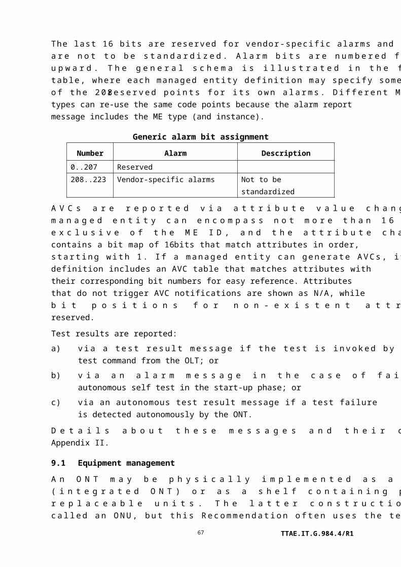
any given time. The following codepoints are defined:
0 Reserved.
1 AES algorithm used for unicast traffic.
2..255 Reserved.
Upon ME instantiation, the ONT sets this attribute to 1, AES. If new encryption modes are standardized, then AES will be the default, and the new modes will be settable via writing to this attribute. This does not mean that any channels are encrypted; that process is negotiated at the PLOAM layer. It only signifies that AES is the security mode to be used on any channels that the OLT may choose to encrypt. (R, W) (mandatory) (1 byte)
TTAE.IT.G.984.4/R167

Total priority queue number:
This attribute reports the total number of upstream priority queues that are not associated with a circuit pack, but with the ONT in its entirety. Upon ME instantiation, the ONT sets this attribute to the value that represents its capabilities. (R) (mandatory) (2 bytes)
Total traffic scheduler number:
This attribute reports the total number of traffic schedulers that are not associated with a circuit pack, but with the ONT in its entirety. The ONT supports null function, HOL scheduling and WRR from the priority control and guarantee of minimum rate control points of view, respectively. If the ONT has no traffic schedulers, this attribute is 0. (R) (mandatory) (1 byte)
Mode: This attribute identifies whether the ONT can operate in ATM-only mode (0), GEM-only mode (1), or both ATM and GEM mode (2). ATM mode is deprecated; this attribute should always be set to 1. (R) (mandatory) (1 byte)
Total GEM port-ID number:
This attribute reports the total number of GEM port-IDs supported by the ONT. The maximum value is 0x0FFF. Upon ME instantiation, the ONT sets this attribute to the value that represents its capabilities. (R) (optional) (2 bytes)
SysUpTime: This attribute counts the 10 ms intervals since the ONT was last initialized. It rolls over to 0 when full (See [b-IETF RFC 1213]). (R) (optional) (4 bytes)
QoS configuration flexibility:
This attribute reports whether various managed entities in the ONT are hard-wired or configurable. For backward compatibility, and if the ONT does not support this attribute, all such attributes are understood to be hard-wired. (R) (optional) (2 bytes)
Bit Model
1 (LSB) Priority queue ME: Related port attribute is read-write and
can point to any T-CONT or UNI port in the same slot
2 Priority queue ME: The traffic scheduler-G pointer is
permitted to refer to any traffic scheduler-G in the same slot
3 Traffic scheduler-G ME: T-CONT pointer is read-write
4 Traffic scheduler-G ME: Policy attribute is read-write
5 T-CONT ME: Policy attribute is read-write
7…16 Reserved
Discussion: To allow for the possibility that the OLT does not support flexible configuration, the ONT vendor must assure that the priority queues
TTAE.IT.G.984.4/R168

and traffic schedulers are configured in a meaningful and useful way by factory default, and that this default configuration is restored upon ONT initialization and MIB reset. The specifics of such a configuration are beyond the scope of this Recommendation.
The managed entity ID of both the T-CONT and traffic scheduler contains a slot number. Even when attributes in the above list are read-write, it is never permitted to change the slot number in a reference. That is, configuration flexibility never extends across slots. It is also not permitted to change the directionality of an upstream queue to downstream, or vice versa.
Actions
Get, set
Notifications
Attribute value change
Number Attribute value change Description
1 N/A
2 OMCC version OMCC version supported in the ONT
3..9 N/A
10..16 Reserved
9.1.3 ONT data
This managed entity models the MIB itself. Clause I.1.2 explains the use of this managed entity with respect to MIB synchronization. Clause I.1.4 explains the alarm synchronization process, in which the get alarm messages are directed to the ONT data managed entity.
The ONT automatically creates an instance of this managed entity, and updates the associated attributes according to data within the ONT itself.
Relationships
One instance of this managed entity is contained in an ONT.
TTAE.IT.G.984.4/R169

Attributes
Managed entity id: This attribute uniquely identifies each instance of this managed entity. There is only one instance, number 0. (R) (mandatory) (2 bytes)
MIB data sync: This attribute is used to check the alignment of the MIB of the ONT with the corresponding MIB in the OLT. MIB data sync relies on this attribute, which is a sequence number that can be checked by the OLT to see if the MIB snapshots for the OLT and ONT match. Refer to clause I.1.1 for a detailed description of this attribute. Upon ME instantiation, the ONT sets this attribute to 0. (R, W) (mandatory) (1 byte)
Actions
Get, set
Get all alarms: Latch a snapshot (i.e., copy) of the current alarm statuses of all managed entities and reset the alarm message counter.
Get all alarms next: Get the latched alarm status of the next managed entity within the current snapshot.
MIB reset: Reset the MIB data sync attribute to 0 and reset the MIB of the ONT to its default state. This default MIB consists of one instance of the ONT-G managed entity, one instance of the ONT data managed entity, two instances of the software image managed entity, zero or more instances of the cardholder managed entity, and zero or more instances of the priority queue-G managed entity (for the priority queues that reside in the ONT).
MIB upload: Latch a snapshot (i.e., copy) of the current MIB. Not every managed entity or every attribute is included in a MIB upload. Table attributes are excluded. Only the control block attributes of performance monitoring MEs are uploaded. Other MEs and attributes, such as the PPTP for the local craft terminal, are excluded as documented in their specific definitions.
MIB upload next: Get the latched attribute values of the managed entity within the current snapshot.
Notifications
None.
9.1.4 Software image
This managed entity models an executable software image stored in the ONT.
TTAE.IT.G.984.4/R170

The ONT automatically creates two instances of this managed entity upon the creation of each managed entity that contains independently-manageable software, either the ONT itself or an individual circuit pack. The ME attributes are populated according to data within the ONT or the circuit pack.
Some pluggable equipments may contain no software. Others may contain software that is intrinsically bound to the ONT's own software image. No software image ME need exist for such equipments, though it may be convenient for the ONT to create them to support software version audit from the OLT. In this case, the dependent MEs would support only the get action.
A slot may contain various equipments over its lifetime, and if software image MEs exist, the ONT must automatically create and delete them as the equipage changes.
When controller packs are duplicated, each can be expected to contain two software image MEs, managed through reference to the individual controller packs themselves. When this occurs, the ONT should not have a global pair of software images MEs (instance 0), since an action (download, activate, commit) directed to instance 0 would be ambiguous.
Relationships
Two instances of the software image managed entity are associated with each instance of the ONT or circuit pack whose software is independently managed.
TTAE.IT.G.984.4/R171

Attributes
Managed entity id: This attribute uniquely identifies each instance of this managed entity. The two-byte value indicates the physical location of the software image. The first byte identifies the ME instance (ONT (0) or slot (1..254)) containing the associated software image ME. The second byte distinguishes between the two software image ME instances (0..1). (R) (mandatory) (2 bytes)
Version: This attribute identifies the version of the software. (R) (mandatory) (14 bytes)
Is committed: This attribute indicates whether the associated software image is committed (1) or uncommitted (0). By definition, the committed software image is loaded and executed upon reboot of the ONT and/or circuit pack. During normal operation, one software image is always committed, while the other is uncommitted. Under no circumstances are both software images allowed to be committed at the same time. On the other hand, both software images could be uncommitted at the same time if both were invalid. Upon ME instantiation, instance 0 is initialized to committed, while instance 1 is initialized to uncommitted (that is, the ONT ships from the factory with image 0 committed). (R) (mandatory) (1 byte)
Is active: This attribute indicates whether the associated software image is active (1) or inactive (0). By definition, the active software image is one that is currently loaded and executing in the ONT or circuit pack. Under normal operation, one software image is always active while the other is inactive. Under no circumstances are both software images allowed to be active at the same time. On the other hand, both software images could be inactive at the same time if both were invalid. (R) (mandatory) (1 byte)
Is valid: This attribute indicates whether the associated software image is valid (1) or invalid (0). By definition, a software image is valid if it has been verified to be an executable code image. The verification mechanism is not subject to standardization; however, at a minimum it must include a data integrity (CRC) check of the entire code image. Upon ME instantiation, the ONT validates the associated code image and sets this attribute according to the result. (R) (mandatory) (1 byte)
Actions
Get
TTAE.IT.G.984.4/R172
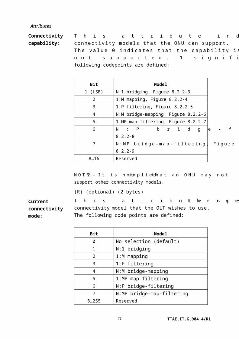
NOTE – Figure 9.1.4-1 illustrates the life cycle of software images under the following actions. State
S0 is a conceptual initialization state when neither of the software images is valid (i.e., executable).
During S0, the OMCC is not functional.
All of the following actions are mandatory for ONTs with remotely manageable software.
Start download: Initiate a software download sequence. This action is valid only for a software image that is currently inactive and uncommitted (i.e., not selected as the boot image).
Download section: Download a section of a software image. This action is valid only for a software image that is currently being downloaded (image 1 in state S2, image 0 in state S2').
End download: Signal the completion of a download sequence, providing both CRC and version information for final verification of a downloaded software image. This action is valid only for a software image that is currently being downloaded (image 1 in state S2, image 0 in state S2').
Activate image: Load/execute a valid software image. When this action is applied to a software image that is currently inactive, execution of the current code image is suspended, the associated software image is loaded from non-volatile memory, and execution of this new code image is initiated (that is, the associated entity re-boots on the previously inactive image). When this action is applied to a software image that is already active, a soft restart is performed. The software image is not reloaded from non-volatile memory; the current volatile code image is simply restarted. This action is only valid for a valid software image.
Commit image: Select a valid software image to be the default image to be loaded and executed by the boot code upon start-up (i.e., set the is committed attribute value to 1 for the associated software image ME and set the is committed attribute value to 0 for the other software image). This action is only valid for a valid software image.
Notifications
None.
TTAE.IT.G.984.4/R173

Figure 9.1.4-1 – Software image state diagram
9.1.5 Cardholder
The cardholder represents the fixed equipment slot configuration of the ONT. One or more of these entities is contained in the ONT. Each cardholder can contain 0 or 1 circuit packs; the
TTAE.IT.G.984.4/R174

circuit pack models equipment information that can change over the lifetime of the ONT, e.g., through replacement.
An instance of this managed entity exists for each physical slot in an ONT that has pluggable circuit packs. One or more instances of this managed entity may also exist in an integrated ONT, to represent virtual slots. Instances of this managed entity are created automatically by the ONT, and the status attributes are populated according to data within the ONT itself.
There is potential for conflict in the semantics of the expected plug-in unit type, the expected port count and the expected equipment id, both when the slot is not populated and when a new circuit pack is inserted. The expected plug-in unit type and the plug-in type mismatch alarm are mandatory, although plug-and-play/unknown (circuit pack type 255) may be used as a way to minimize their significance. It is recommended that an ONT deny the provisioning of inconsistent combinations of expected equipment attributes.
When a circuit pack is plugged into a cardholder, or when a cardholder is preprovisioned to expect a circuit pack of a given type, it may trigger the ONT to instantiate a number of managed entities and update the values of others, depending on the circuit pack type. The ONT may also delete a variety of other managed entities when a circuit pack is reprovisioned to expect no circuit pack or a circuit pack of a different type. These actions are described in the definitions of the various managed entities.
Expected equipment id and expected port count are alternate ways to trigger the same preprovisioning effects. These tools may be useful if an ONT is prepared to accept more than one circuit pack of a given type but with different port counts, or if a circuit pack is a hybrid that matches none of the types in Table 9.1.5-1, but whose identification (e.g., part number) is known.
Relationships
An ONT may contain one or more instances of the cardholder, each of which may contain an instance of the circuit pack managed entity. The slot id, real or virtual, is a fundamental identification mechanism for managed entities with some relationship to physical location.
Attributes
Managed entity id: This attribute uniquely identifies each instance of this managed entity. The ONT sets the first byte of this two-byte identifier to:
0 if the ONT contains pluggable equipment modules;1 if the ONT is a single integrated equipment.
The second byte of this identifier is the slot number. In integrated ONTs, this byte may be used as a virtual slot or set to 0 to indicate a universal pseudo-slot.
Slot numbering schemes differ among vendors. It is only required
TTAE.IT.G.984.4/R175

that slot numbers be unique across the ONT. Up to 254 equipment slots are supported in the range 1..254 (Note 1). The value 0 is reserved to indicate a universal pseudo-slot. The value 255 is also reserved. (R) (mandatory) (2 bytes)
NOTE 1 – Some xDSL managed entities use the two most significant bits of the slot number for other purposes. An ONT that supports these services may have slot limitations or restrictions.
TTAE.IT.G.984.4/R176

Actual plug-in unit type:
This attribute is equal to the type of the circuit pack in the cardholder or 0 if the cardholder is empty. This attribute is then redundant with the type attribute of the circuit pack managed entity. Circuit pack types are defined in Table 9.1.5-1. (R) (mandatory) (1 byte)
The three following attributes permit the OLT to specify its intentions for future equipage of a slot. Once some or all of these are set, the ONT can proceed to instantiate circuit pack and PPTP MEs, along with other predeterminable MEs, and allow the OLT to create related discretionary MEs, thereby supporting service preprovisioning.
Expected plug-in unit type:
This attribute provisions the type of circuit pack for the slot. For type coding, see Table 9.1.5-1. The value 0 means that the cardholder is not provisioned to contain a circuit pack. The value 255 means that the cardholder is configured for plug-and-play. Upon ME instantiation, the ONT sets this attribute to 0. For integrated interfaces, this attribute may be used to represent the type of interface. (R, W) (mandatory) (1 byte)
Expected port count: This attribute permits the OLT to specify the number of ports it expects in a circuit pack. Prior to provisioning by the OLT, the ONT initializes this attribute to 0. (R, W) (optional) (1 byte)
Expected equipment id:
This attribute provisions the specific type of expected circuit pack. This attribute applies only to ONTs that do not have integrated interfaces. In North America, this may be the expected equipment CLEI code. Upon ME instantiation, the ONT sets this attribute to all spaces. (R, W) (optional) (20 bytes)
Actual equipment id: This attribute identifies the specific type of circuit pack, once it is installed. This attribute applies only to ONTs that do not have integrated interfaces. In North America, this may be the equipment CLEI code. When the slot is empty or the equipment ID is not known, this attribute should be set to all spaces. (R) (optional) (20 bytes)
Protection profile pointer:
This attribute indicates an equipment protection profile that may be associated with the cardholder. Its value is the least significant byte of the managed entity ID of the equipment protection profile with which it is associated, or 0 if equipment protection is not used. (R) (optional) (1 byte)
Invoke protection The OLT may use this attribute to control equipment protection
TTAE.IT.G.984.4/R177

switch: switching. Code points have the following meaning when set by the OLT:
0 Release protection switch.1 Operate protection switch, protect cardholder unspecified.2 Operate protection switch, use first protect cardholder.3 Operate protection switch, use second protect cardholder.
The ONT should deny attempts to switch to an unequipped, defective or already active protection cardholder.
Upon the get action from the OLT, this attribute should return the current value of the actual protection configuration. Code points are as defined above, except that the value 1 is never returned.
When circuit packs that support a PON IF function are switched, the response should be returned on the same PON that received the command. However, the OLT should also be prepared to accept a response on the redundant PON. (R, W) (optional) (1 byte)
ARC: See clause I.1.8. (R, W) (optional) (1 byte)
ARC interval: See clause I.1.8. (R, W) (optional) (1 byte)
Actions
Get, set
Notifications
Attribute value change
Number Attribute value change Description
1 Actual type Actual type of circuit pack in cardholder
2..4 N/A
5 Actual equipment id Actual equipment ID of circuit pack in cardholder
6..7 N/A
8 ARC ARC timer expiration
9..16 Reserved
Alarm: If no circuit pack is configured or if the cardholder is configured for plug-and-play with no expected equipment ID, no alarms are raised. No alarms are defined for ONTs with integrated interfaces.
TTAE.IT.G.984.4/R178

Number Alarm Description
0 Plug-in LIM missing alarm Configured circuit pack is not present. If the plug-in LIM
missing alarm is active, none of the mismatch alarms are
declared.
1 Plug-in type mismatch alarm Inserted circuit pack is wrong type
2 Improper card removal Circuit pack has been removed without being de-provisioned.
This is a redundant alarm that helps the OLT distinguish
between transitions from state S2 to state S1 (Figure 9.1.5-1)
and transitions from state S4 to state S1. This alarm is sent
only when a transition occurs from state S2 to state S1.
3 Plug in equipment id
mismatch alarm
Inserted circuit pack has wrong equipment ID
4 Protection switch An autonomous equipment protection switch has occurred.
This notification is reported by the protected cardholder.
5..207 Reserved
208..223 Vendor-specific Not to be standardized
Figure 9.1.5-1 is a state diagram that describes insertion and removal of a particular circuit pack into/from a cardholder that is provisioned to a specific type or to plug-and-play.
NOTE 2 – The state diagram is not applicable for ONTs with integrated interfaces.
TTAE.IT.G.984.4/R179

Figure 9.1.5-1 – Cardholder state diagram
Some of the following circuit pack types are obsolete in G-PON applications. Their code points and definitions are reserved for backward compatibility but, in the interest of brevity, they are not listed.
TTAE.IT.G.984.4/R180

Table 9.1.5-1 – Circuit pack types
Coding Content Description
0 No LIM Default value
1..12 See [ITU-T G.983.2] Various ATM-based UNIs
13 C1.5 (DS1) 1.544 Mbit/s local (T-interface) module
14 C2.0 (E1) 2.048 Mbit/s local (T-interface) module
15 C6.3 (J2) 6.312 Mbit/s local (T-interface) module
16 C-DS1/E1 Configurable DS1/E1 module
17 C-DS1/E1/J1 Configurable DS1/E1/J1 module
18 C6.3U (J2) 6.312 Mbit/s remote (U-interface) module
19 C192k 192 kbit/s local (T-interface) module
20 C44.7 (DS3) 44.736 Mbit/s local (T-interface) module
21 C34.3 (E3) 34.368 Mbit/s local (T-interface) module
22 10BaseT 10 BaseT Ethernet LAN IF
23 100BaseT 100 BaseT Ethernet LAN IF
24 10/100BaseT 10/100 BaseTx Ethernet LAN IF (Note)
25..27 See [ITU-T G.983.2] Various non-Ethernet LAN technologies
28 C1.5 (J1) 1.544 Mbit/s local (T-interface) module
29 A150SMF SONET ATM OC-3 SMF UNI
30 A150MMF SONET ATM OC-3 MMF UNI
31 A150UTP SONET ATM OC-3 UTP UNI
32 POTS Plain old telephony service
33 ISDN-BRI ISDN basic rate interface
34 Gigabit optical Ethernet Gigabit Ethernet optical IF (Note)
35 xDSL xDSL IF
36 SHDSL SHDSL IF
37 VDSL VDSL IF ([ITU-T G.993.1])
38 Video service Video module
39 LCT Local craft terminal interface
40 802.11 [IEEE 802.11] interface
41 xDSL/POTS Combination xDSL and POTS interfaces
42 VDSL/POTS Combination VDSL ([ITU-T G.993.1]) and POTS interfaces
43 Common equipment Circuit packs such as removable power supply modules or
ONU controllers
44 Combined video UNI and
PON interface
Circuit pack that combines both functions
TTAE.IT.G.984.4/R181

Table 9.1.5-1 – Circuit pack types
Coding Content Description
45 Mixed services equipment Circuit pack with several types of ANI and/or UNI. Suggested
for use with the port mapping package-G managed entity.
46 MoCA MoCA
47 10/100/1000BaseT 10/100/1000 BaseTx Ethernet LAN IF (Note)
48.. 191 Reserved
192..223 Vendor-specific Reserved for vendor use, not to be standardized
224..242 Reserved
239 Mid-span PON reach
extender UNI
The UNI of a mid-span PON reach extender, 2488
Mbit/s downstream and 1244 Mbit/s upstream
240 Mid-span PON reach
extender ANI
The ANI of a mid-span PON reach extender, 2488
Mbit/s downstream and 1244 Mbit/s upstream
241 Mid-span PON reach
extender upstream optical
amplifier
The 1310 nm wavelength optical amplifier
242 Mid-span PON reach
extender downstream
optical amplifier
The 1490 nm wavelength optical amplifier
246 GPON2488155 G-PON interface, 2488 Mbit/s downstream and 155 Mbit/s
upstream
247 GPON2488622 G-PON interface, 2488 Mbit/s downstream and 622 Mbit/s
upstream
248 GPON24881244 G-PON interface, 2488 Mbit/s downstream and 1244 Mbit/s
upstream
249 GPON24882488 G-PON interface, 2488 Mbit/s downstream and 2488 Mbit/s
upstream
250..254 See [ITU-T G.983.2] G-PON and B-PON interfaces of diverse rates
255 Plug-and-play/unknown Plug-and-play (for the cardholder managed entity only).
Unrecognized module (for the circuit pack managed entity
only).
NOTE – Codepoints 24 and 34 were used by some implementations to represent the 10/100/1000BaseT
interface because codepoint 47 was not defined at the time. While codepoint 47 should be adopted for this
interface at the earliest opportunity, near-term interoperability may require the flexible recognition of these
other codepoints.
TTAE.IT.G.984.4/R182

9.1.6 Circuit pack
This managed entity models a circuit pack that is equipped in an ONT slot. For ONTs with integrated interfaces, this managed entity may be used to distinguish available types of interfaces (the port mapping package is another way).
For ONTs with integrated interfaces, the ONT automatically creates an instance of this managed entity for each instance of the virtual cardholder managed entity. The ONT also creates an instance of this managed entity when the OLT provisions the cardholder to expect a circuit pack (i.e., when the OLT sets the expected plug-in unit type or equipment ID of the cardholder to a circuit pack type, as defined in clause 9.1.5). The ONT also creates an instance of this managed entity when a circuit pack is installed in a cardholder whose expected plug-in unit type is 255 = plug-and-play, and whose equipment ID is not provisioned. Finally, when the cardholder is provisioned for plug-and-play, an instance of this managed entity can be created at the request of the OLT.
The ONT deletes an instance of this managed entity when the OLT de-provisions the circuit pack (i.e., when the OLT sets the expected plug-in unit type or equipment ID of the cardholder to 0 = no LIM). The ONT also deletes an instance of this managed entity on request of the OLT if the expected plug-in unit type attribute of the corresponding cardholder is equal to 255, plug-and-play, and the expected equipment ID is blank (a string of all spaces). ONTs with integrated interfaces do not delete circuit pack instances.
NOTE – Creation and deletion by the OLT is retained for backward compatibility.
Relationships
An instance of this managed entity is contained by an instance of the cardholder managed entity.
Attributes
TTAE.IT.G.984.4/R183

Managed entity id: This attribute uniquely identifies each instance of this managed entity. Its value is the same as that of the cardholder managed entity containing this circuit pack instance. (R, Set-by-create (if applicable)) (mandatory) (22 bytes)
Type: This attribute identifies the circuit pack type. This attribute is a code as defined in Table 9.1.5-1. The value 255 means unknown or undefined, i.e., the inserted circuit pack is not recognized by the ONT or is not mapped to an entry in Table 9.1.5-1. In the latter case, the equipment ID attribute may contain inventory information. Upon autonomous ME instantiation, the ONT sets this attribute to 0 or to the type of the circuit pack that is physically present. (R, Set-by-create (if applicable)) (mandatory) (1 byte)
Number of ports: This attribute is the number of access ports on the circuit pack. If the port mapping package-G is supported for this circuit pack, this attribute should be set to the total number of ports of all types. (R) (optional) (1 byte)
Serial number: The serial number is unique for each circuit pack. Note that the serial number may contain the vendor ID and/or version number. For integrated ONTs, this value is identical to the value of the serial number attribute of the ONT-G managed entity. Upon creation in the absence of a physical circuit pack, this attribute comprises all spaces. (R) (mandatory) (8 bytes)
Version: This attribute is a string that identifies the version of the circuit pack as defined by the vendor. The value 0 indicates that version information is not available or applicable. For integrated ONTs, this value is identical to the value of the version attribute of the ONT-G managed entity. Upon creation in the absence of a physical circuit pack, this attribute comprises all spaces. (R) (mandatory) (14 bytes)
Vendor id: This attribute identifies the vendor of the circuit pack. For ONTs with integrated interfaces, this value is identical to the value of the vendor ID attribute of the ONT-G managed entity. Upon creation in the absence of a physical circuit pack, this attribute comprises all spaces. (R) (optional) (4 bytes)
TTAE.IT.G.984.4/R184

Administrative state: This attribute locks (1) and unlocks (0) the functions performed by the circuit pack. When the administrative state is set to lock, all user functions of this circuit pack are blocked, and alarms, TCAs and AVCs for this managed entity and all dependent managed entities are no longer generated. Selection of a default value for this attribute is outside the scope of this Recommendation. (R, W, Set-by-create (if applicable)) (mandatory) (1 byte)
Operational state: This attribute indicates whether or not the circuit pack is capable of performing its function. Valid values are enabled (0), disabled (1) and unknown (2). Pending completion of initialization and self test on an installed circuit pack, the ONT sets this attribute to 2. (R) (optional) (1 byte)
TTAE.IT.G.984.4/R185

Bridged or IP ind: This attribute specifies whether the Ethernet interface is bridged or derived from an IP router function.
0 Bridged.1 IP router.2 Both bridged and IP router functions.
(R, W) (optional, only applicable for circuit packs with Ethernet interfaces) (1 byte)
Equipment id: This attribute may be used to identify the vendor's specific type of circuit pack. In North America, this may be the CLEI code. Upon ME instantiation, the ONT sets this attribute to all spaces or to the equipment ID of the circuit pack that is physically present. (R) (optional) (20 bytes)
Card configuration: This attribute selects the appropriate configuration on configurable circuit packs (e.g., T1/E1). Table 9.1.5-1 specifies three configurable card types: A45/34 (code 9), C-DS1/E1 (code 16), and C-DS1/E1/J1 (code 17). Values are indicated below for the allowed card types and configurations.
Card type Configuration Value
A45/34 ATM 44.736 Mbit/s 0
ATM 34.368 Mbit/s 1
C-DS1/E1 DS1 0
E1 1
C-DS1/E1/J1 DS1 0
E1 1
J1 2
Upon autonomous instantiation, this attribute is set to 0. (R, W, Set-by-create (if applicable)) (mandatory for configurable circuit packs) (1 byte)
Total T-CONT buffer number:
This attribute reports the total number of T-CONT buffers associated with the circuit pack. Upon ME instantiation, the ONT sets this attribute to 0 or to the value supported by the physical circuit pack. (R) (mandatory for circuit packs that provide a traffic scheduler function) (1 byte)
TTAE.IT.G.984.4/R186

Total priority queue number:
This value reports the total number of priority queues associated with the circuit pack. Upon ME instantiation, the ONT sets the attribute to 0 or to the value supported by the physical circuit pack. (R) (mandatory for circuit packs that provide a traffic scheduler function) (1 byte)
Total traffic scheduler number:
This value reports the total number of traffic schedulers associated with the circuit pack. The ONT supports null function, HOL (head of line) scheduling and WRR (weighted round robin) from the priority control and guarantee of minimum rate control points of view, respectively. If the circuit pack has no traffic scheduler, this attribute should be 0. Upon ME instantiation, the ONT sets the attribute to 0 or to the value supported by the physical circuit pack. (R) (mandatory for circuit packs that provide a traffic scheduler function) (1 byte)
Power shed override: This attribute allows ports to be excluded from the power shed control defined in clause 9.1.7. It is a bit mask that takes port 1 as the MSB; a bit value of 1 marks the corresponding port to override the power shed timer. For hardware that cannot shed power per port, this attribute is a slot override rather than a port override, with any non-zero port value causing the entire circuit pack to override power shedding. (R, W) (optional) (4 bytes)
Actions
Get, set
Create, delete: Optional, only when plug-and-play is supported.
Reboot: Reboot the circuit pack.
Test: Test the circuit pack (optional). The test action may be used either to perform equipment diagnostics or to measure parameters such as received optical power, video output level, battery voltage, etc. Extensions to the test and test response messages are defined for these purposes; refer to Appendix II.
Notifications
Attribute value change
Number Attribute value change Description
1..6 N/A
7 Op state Operational state change
TTAE.IT.G.984.4/R187

8..14 N/A
15..16 Reserved
Alarm
Number Alarm Description
0 Equipment alarm A failure on an internal interface or failed self test
1 Powering alarm Fuse failure or failure of DC/DC converter
2 Self test failure Failure of circuit pack autonomous self test
3 Laser end of life Failure of transmit laser imminent
4 Temperature yellow No service shutdown at present, but the circuit pack
is operating beyond its recommended range
5 Temperature red Service has been shut down to avoid equipment
damage. The operational state of the affected PPTPs
indicates the affected services
6..207 Reserved
208..223 Vendor-specific alarms Not to be standardized
9.1.7 ONT power shedding
This managed entity models the ONT's ability to shed services when the ONT goes into battery operation mode after AC power failure. Shedding classes are defined, which may span multiple circuit pack types. This feature works in conjunction with the power shed override attribute of the circuit pack managed entity, which can selectively prevent power shedding of priority ports.
An ONT that supports power shedding automatically creates an instance of this managed entity.
The following table defines the binding of shedding class and PPTP type. The coding is taken from Table 9.1.5-1. In the case of hybrid LIM types, multiple shedding classes may affect a circuit pack if the hardware is capable of partial power shedding.
An ONT may choose to model its ports with the port mapping package-G of clause 9.1.8, rather than with real or virtual circuit packs. In this case, power shedding pertains to individual PPTPs, as listed in the second column of the table.
Shedding class PPTP type Coding Content
ATM ATM PPTP 1..12 Various ATM UNIs
CES CES PPTP 13 C1.5 (DS1)
14 C2.0 (E1)
TTAE.IT.G.984.4/R188

Shedding class PPTP type Coding Content
15 C6.3 (J2)
16 C-DS1/E1
17 C-DS1/E1/J1
18 C6.3U (J2)
19 C192k
20 C44.7 (DS3)
21 C34.3 (E3)
Data Ethernet PPTP 22 10BaseT
23 100BaseT
24 10/100BaseT
Frame Unspecified 25..27 Non-Ethernet LANs
CES CES PPTP 28 C1.5 (J1)
SONET SONET 29 A150SMF SONET
30 A150MMF SONET
31 A150UTP SONET
Voice POTS PPTP 32 POTS
ISDN PPTP 33 ISDN-BRI
Data Ethernet PPTP 34 Gigabit optical Ethernet
DSL xDSL PPTP 35 xDSL
Unspecified 36 SHDSL
VDSL PPTP 37 [ITU-T G.993.1] VDSL
N/A Video UNI 38 Video service
N/A LCT PPTP 39 LCT
Data 802.11 PPTP 40 802.11
Voice (DSL may also apply) xDSL + POTS 41 xDSL/POTS
VDSL + POTS 42 [ITU-T G.993.1] VDSL/POTS
N/A Unspecified 43 Common equipment
Unspecified 44 Combined video, PON
Unspecified 45 Mixed services (power
shedding based on port type)
Data MOCA PPTP 46 MoCA
Data Ethernet PPTP 47 10/100/1000BaseT
N/A PON PPTP 243..254 G-PON and B-PON ANIs
Video overlay Video ANI PPTP
Video return Video RPD
Relationships
TTAE.IT.G.984.4/R189

One instance of this managed entity is associated with the ONT managed entity.
Attributes
Managed entity id: This attribute uniquely identifies each instance of this managed entity. There is only one instance, number 0. (R) (mandatory) (2 bytes)
Restore power timer reset interval:
The time delay, in seconds, before resetting shedding timers after full power restoration. Upon ME instantiation, the ONT sets this attribute to 0. (R, W) (mandatory) (2 bytes)
For each class of service, an interval attribute is defined below. The value 0 disables power shedding, while the value 1 enables immediate power shed, that is, as soon as AC power fails. Other values specify the time, in seconds, to keep the service active after AC failure before shutting them down and shedding power. Upon ME instantiation, the ONT sets each of the interval attributes to 0.
Data class shedding interval:
(R, W) (mandatory) (2 bytes)
Voice class shedding interval:
Note that this attribute only pertains to voice services that terminate on the ONT, not to voice services that may reside in the customer premises served by a data type port. (R, W) (mandatory) (2 bytes)
Video overlay class shedding interval:
(R, W) (mandatory) (2 bytes)
Video return class shedding interval:
(R, W) (mandatory) (2 bytes)
DSL class shedding interval:
(R, W) (mandatory) (2 bytes)
ATM class shedding interval:
(R, W) (mandatory) (2 bytes)
CES class shedding interval:
(R, W) (mandatory) (2 bytes)
Frame class shedding interval:
(R, W) (mandatory) (2 bytes)
SONET class shedding interval:
(R, W) (mandatory) (2 bytes)
TTAE.IT.G.984.4/R190
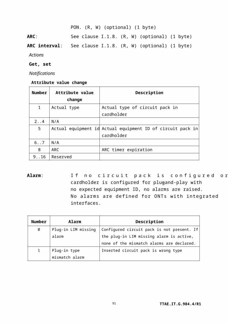
Shedding status: Boolean indication of power shedding status for each shedding class. If this two-byte field is depicted 0b ABCD EFGH IJKL MNOP, its bits are assigned:
A Data classB Voice classC Video overlay classD Video return classE DSL classF ATM classG CES classH Frame classI SONET classJ..P Reserved and set to 0
The ONT sets each bit when power shedding is active, and clears it when the service is restored. (R) (optional) (2 bytes)
Actions
Get, set
Notifications
Attribute value change
Number Attribute value change Description
1..10 N/A
11 Shedding status State change of a shedding function
12..16 Reserved
9.1.8 Port mapping package-G
This managed entity provides a way to map a heterogeneous set of physical path termination points (ports) to a parent equipment, which may be a cardholder or the ONT itself. It could be useful, for example, if a single plug-in circuit pack contained a PON ANI as port 1, a video UNI as port 2, and a craft UNI as port 3. It also provides an option for an integrated ONT to represent its ports without the use of virtual cardholders and virtual circuit packs.
If the port mapping package-G is supported for the ONT as a whole, it is automatically created by the ONT. If the port mapping package-G is supported for plug-in circuit packs, it is created and destroyed by the ONT when the corresponding circuit pack is installed or preprovisioned in a cardholder.
The port list attributes specify ports 1..64 sequentially. Each port list contains a sequence of ME types, as defined in Table 11-2. These ME type codes define what kind of PPTP or ANI
TTAE.IT.G.984.4/R191

corresponds to the specific port number. For example, for a circuit pack with 4 POTS ports, 2 VDSL ports, and 1 video port, numbered sequentially in that order, the attributes would be coded:
Max ports: 7
Port list 1: 53, 53, 53, 53, 117, 117, 82, 0
Port list 2..8: All zero
Relationships
A port mapping package-G may be contained by an ONT-G or a cardholder.
Attributes
Managed entity id: This attribute uniquely identifies each instance of this managed entity. Through an identical ID, this managed entity is implicitly linked to an instance of the ONT-G or cardholder. (R) (mandatory) (2 bytes)
Max ports: This attribute indicates the largest port number contained in the port list attributes. Ports are numbered from 1 to this maximum, possibly with embedded 0 entries, but no port may exist beyond the maximum. (R) (mandatory) (1 byte)
Each of the following attributes is a list of 8 ports, in increasing port number sequence. Each list entry is a two-byte field containing the managed entity type of the UNI or ANI corresponding to the port number. Managed entity types are defined in Table 11-2. Placeholders for unused port numbers are indicated with the value 0.
Port list 1: (R) (mandatory) (16 bytes)
Port list 2: (R) (optional) (16 bytes)
Port list 3: (R) (optional) (16 bytes)
Port list 4: (R) (optional) (16 bytes)
Port list 5: (R) (optional) (16 bytes)
Port list 6: (R) (optional) (16 bytes)
Port list 7: (R) (optional) (16 bytes)
Port list 8: (R) (optional) (16 bytes)
Actions
Get
Notifications
TTAE.IT.G.984.4/R192

None.
9.1.9 Equipment extension package
This managed entity supports optional extensions to circuit pack managed entities. If the circuit pack supports these features, the ONT creates and deletes this managed entity along with its associated real or virtual circuit pack.
Relationships
An equipment extension package may be contained by an ONT-G or cardholder.
Attributes
Managed entity id: This attribute uniquely identifies each instance of this managed entity. Through an identical ID, this managed entity is implicitly linked to an instance of the ONT-G or cardholder. (R) (mandatory) (2 bytes)
TTAE.IT.G.984.4/R193

Environmental sense: This attribute provisions an ONT that supports external sense points, for example physical security detectors at an enclosure. Each pair of bits is defined as follows:
00 Sense point disabled (default).01 Report contact closure.10 Report contact open.11 Sense point disabled (same as 00).
If the byte is represented in binary as 0B hhgg ffee ddcc bbaa, bits hh correspond to sense point 1, while bits aa correspond to sense point 8. (R, W) (optional) (2 bytes)
NOTE – Some specific sense point applications are already defined on the ONT-G managed entity. It is the vendor's choice how to configure and report sense points that appear both generically and specifically.
Contact closure output:
This attribute provisions an ONT that supports external contact closure outputs, for example sump pump or air conditioner activation at an ONT enclosure. A contact point is said to be released when it is not energized. Whether this corresponds to an open or a closed electrical circuit depends on the ONT's wiring options. Upon ONT initialization, all contact points should go to the released state.
If the byte is represented in binary as 0B hhgg ffee ddcc bbaa, bits hh correspond to contact output point 1, while bits aa correspond to contact output point 8.
On write, the bits of this attribute have the following meaning:
0x No change to contact output point state.10 Release contact output point.11 Operate contact output point.
On read, the left bit in each pair should be set to 0 at the ONT and ignored at the OLT. The right bit indicates a released output point with 0 and an operated point with 1. (R, W) (optional) (2 bytes)
Actions
Get, set
Notifications
Alarm
TTAE.IT.G.984.4/R194
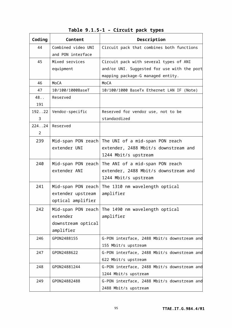
Number Alarm Description
0 Reserved
1 Sense point 1 Environmental sense point 1 active
2 Sense point 2 Environmental sense point 2 active
3 Sense point 3 Environmental sense point 3 active
4 Sense point 4 Environmental sense point 4 active
5 Sense point 5 Environmental sense point 5 active
6 Sense point 6 Environmental sense point 6 active
7 Sense point 7 Environmental sense point 7 active
8 Sense point 8 Environmental sense point 8 active
9..207 Reserved
208..223 Vendor-specific alarms Not to be standardized
9.1.10 Protection data
This managed entity models the capability and parameters of PON protection. An ONT that supports PON protection automatically creates one instance of this managed entity. A chassis-based reach extender could have the capability of protecting a number of PONs, possibly by way of circuit packs configured in arbitrary (rather than predefined) slots. Protection data managed entities in a multi-PON reach extender may therefore be auto-created or created by the OLT, depending on the reach extender's architecture, and the ANI-G pointers may be either populated by the ONT itself (read-only) or configured by the OLT (read-write, set-by-create). Likewise, the nature of protection may be set read-only by the ONT's architecture, or may be settable by the OLT.
NOTE 1 – Equipment protection is modelled with the equipment protection profile and cardholder
managed entities.
NOTE 2 – For ONTs that implement reach extender functions, this ME can be used to describe OMCI
protection, reach extender R'/S' protection, or both. For reach extender R'/S' protection, the protection
type must be 1:1 without extra traffic, because the switching is done on a link-by-link basis, and the
protection link is in cold standby mode. The instance that pertains to OMCI protection has ME ID = 0.
Relationships
One instance of this managed entity is associated with two instances of the ANI-G, RE ANI-G or RE upstream amplifier. One of the ANI managed entities represents the working side; the other represents the protection side.
Attributes
Managed entity id: This attribute uniquely identifies each instance of this managed entity. If there is more than one protection data ME, they are numbered in ascending order from 0. (R, Set-by-create (if
TTAE.IT.G.984.4/R195

applicable)) (mandatory) (2 bytes)
Working ANI-G pointer:
This attribute points to the ANI-G, RE ANI-G or RE upstream amplifier managed entity that represents the working side of a protected PON. (R, W (if applicable), Set-by-create (if applicable)) (mandatory) (2 bytes)
NOTE 3 – It is possible, and indeed likely, that an ANI-G will have the same ME ID as the RE ANI-G or even the RE upstream amplifier that supports its physical PON interface. The ANI-G represents the embedded ONT that terminates the OMCC. Since it is not expected that the protection of management communications will be implemented independently from the protection of the optical layer, the ambiguity is not expected to cause a problem.
Protection ANI-G pointer:
This attribute points to the ANI-G, RE ANI-G or RE upstream amplifier managed entity that represents the protection side of a protected PON. (R, W (if applicable), Set-by-create (if applicable)) (mandatory) (2 bytes)
Protection type: This attribute indicates the type of PON protection. Valid values are:
0 1+1 protection
1 1:1 protection without extra traffic
2 1:1 protection with ability to support extra traffic
(R, W (if applicable), Set-by-create (if applicable)) (mandatory) (1 byte)
Revertive ind: This attribute indicates whether protection is revertive (1) or non-revertive (0). (R, W (if applicable), Set-by-create (if applicable)) (mandatory) (1 byte)
Wait to restore time: This attribute specifies the time, in seconds, to wait after a fault clear before switching back to the working side. Upon ME instantiation, the ONT sets this attribute to 3 seconds. (R, W, Set-by-create (if applicable)) (mandatory) (2 bytes)
Switching guard time: This attribute specifies the time, in milliseconds, to wait after the detection of a fault before performing a protection switch. Selection of a default value for this attribute is outside the scope of this Recommendation, as it is normally handled through supplier-operator negotiations. (R, W, Set-by-create (if
TTAE.IT.G.984.4/R196

applicable)) (optional) (2 bytes)
Actions
Create, delete (if applicable)
Notifications
None.
9.1.11 Equipment protection profile
This managed entity supports equipment protection. There can be as many as two protection slots protecting as many as eight working slots. Each of the working and protect cardholder managed entities should refer to the equipment protection profile that defines its protection group. Instances of this managed entity are created and deleted by the OLT.
An ONT should deny pre-provisioning that would create impossible protection groupings because of slot or equipment incompatibilities. In the same way, the ONT should deny creation or addition to protection groups that cannot be supported by the current equipage. Even so, an inconsistent card type alarm is defined, for example to cover the case of a plug-and-play circuit pack installed in a protection group cardholder that cannot support it.
Relationships
An instance of this object points to the working and protect cardholders, which in turn point back to this managed entity.
Attributes
Managed entity id: This attribute uniquely identifies each instance of this managed entity. The first byte is 0. The second byte is assigned by the OLT, and must be unique and non-zero. (R, Set-by-create) (mandatory) (2 bytes)
Protect slot 1,protect slot 2:
This pair of attributes describes the protecting cardholder entities in an equipment protection group. There can be one or two protecting entities.
0 Undefined entry (default), a place-holder if there are fewer than two protecting entities in the protection group.
1..254 Slot number of the protecting circuit pack.
(R, W, Set-by-create) (at least one entry mandatory) (1 byte * 2 attributes)
working slot 1,working slot 2,working slot 3,
This group of attributes describes the working cardholder entities in an equipment protection group. There can be up to eight working entities.
TTAE.IT.G.984.4/R197

working slot 4,working slot 5,working slot 6,working slot 7,working slot 8
0 Undefined entry (default), a place-holder if there are fewer than eight working entities in the protection group.
1..254 Slot number of the working circuit pack.
(R, W, Set-by-create) (at least one entry mandatory) (1 byte * 8 attributes)
Protect status 1, protect status 2:
This pair of attributes indicates whether each protection cardholder is currently protecting some other cardholder and, if so, which one.
0 Not protecting any other cardholder.1..254 Slot number of the working cardholder currently being
protected by this ME.
(R) (mandatory) (1 byte * 2 attributes)
Revertive ind: This attribute specifies whether equipment protection is revertive. The default value 0 indicates revertive switching; any other value indicates non-revertive switching. (R, W, Set-by-create) (optional) (1 byte)
Wait to restore time: This attribute specifies the time, in minutes, during which a working equipment must be free of error before a revertive switch occurs. It defaults to 0. (R, W, Set-by-create) (optional) (1 byte)
Actions
Create, delete, get, set
Notifications
Alarm
Number Alarm Description
0 Inconsistent card type The expected or actual circuit pack type in a slot is
incapable of participating in the equipment protection
group, either because it is not subject to equipment
protection or because its type or equipment ID differs
from that previously defined for the other cardholders of
the group. When possible, the ONT should deny
provisioning attempts that would create incompatibilities
but, for example, in the case of plug-and-play, it may not
be possible to forestall the inconsistency.
1..207 Reserved
208..223 Vendor-specific alarms Not to be standardized
TTAE.IT.G.984.4/R198

9.1.12 ONT remote debug
This managed entity is used to send vendor-specific debug commands to the ONT and receive vendor-specific replies back for processing on the OLT. This allows for the remote debugging of an ONT that may not be accessible by any other means. The command format may have two modes, one being text and the other free format. In text format, both the command and reply are ASCII strings. In free format, the content and format of command and reply are vendor-specific.
An ONT that supports remote debugging automatically creates an instance of this managed entity. It is not reported during a MIB upload.
Relationships
One instance of this managed entity is associated with the ONT managed entity.
Attributes
Managed entity id: This attribute uniquely identifies each instance of this managed entity. There is only one instance, number 0. (R) (mandatory) (2 bytes)
Command format: This attribute defines the format of the command and reply attributes. Value 0 defines ASCII string format, while 1 specifies free format. (R) (mandatory) (1 byte)
Command: This attribute is used to send a command to the ONT. The format of the command is defined by the command format. If the format is ASCII string, the command should be null terminated unless the string is 25 bytes long. The action of setting this attribute should trigger the ONT to discard any previous command reply information and execute the current debugging command. (W) (mandatory) (25 bytes)
Reply table: This attribute is used to pass reply information back to the OLT. Its format is defined by the command format attribute. The get, get next action sequence must be used with this attribute, since its size is unspecified. (R) (mandatory) (N bytes)
Actions
Get, get next, set
Notifications
None.
TTAE.IT.G.984.4/R199

9.1.13 ONT-E
This managed entity represents a point-to-point Gigabit Ethernet-fed ONT as equipment, as defined in [ITU-T G.986]. The ONT automatically creates an instance of this managed entity. It assigns values to read-only attributes according to data within the ONT itself.
Relationships
All other managed entities in this Recommendation are related directly or indirectly to the ONT-E entity.
Attributes
Managed entity id: This attribute uniquely identifies each instance of this managed entity. There is only one instance, number 0. (R) (mandatory) (2 bytes)
Vendor id: This attribute identifies the vendor of the ONT. Both the code set for the Vendor_ID, specified in [ATIS-0300220] and the organizationally unique identifier (OUI) specified in clause 9 of [IEEE 802], could be applied for this attribute.
When the code set for the Vendor_ID, specified in [ATIS-0300220], is applied for this attribute, the 4 characters are mapped into the 4-byte field by concatenating the ASCII/ANSI character codes.
When the OUI is applied for this attribute, the 3 characters are mapped into the 4-byte field with 0xFF assigned to the first octet.
(R) (mandatory) (4 bytes)
OctetContent
Vendor_ID in [ATIS-0300220] OUI in [IEEE 802]
1 First byte of Vendor_ID 0xFF
2 Second byte of Vendor_ID First byte of OUI
3 Third byte of Vendor_ID Second byte of OUI
4 Fourth byte of Vendor_ID Third byte of OUI
Version: This attribute identifies the version of the ONT as defined by the vendor. The character value "0" indicates that version information is not available or applicable. (R) (mandatory) (14 bytes)
Serial number: The serial number is unique for each ONT. It is defined by the vendor.
TTAE.IT.G.984.4/R1100

The character value "0" indicates that serial number information is not available or applicable. (R) (mandatory) (8 bytes)
Actions
Get
Reboot: Reboot the ONT
Notifications
Alarm
Number Alarm Description
0 Equipment alarm Functional failure on an internal interface
1..207 Reserved
208..223 Vendor-specific alarms Not to be standardized
9.2 ANI management
9.2.1 ANI-G
This managed entity organizes data associated with each access network interface supported by the ONT. The ONT automatically creates one instance of this managed entity for each PON physical port.
Relationships
An instance of this managed entity is associated with each instance of a physical PON interface.
Attributes
TTAE.IT.G.984.4/R1101

Managed entity id: This attribute uniquely identifies each instance of this managed entity. Its value indicates the physical position of the PON IF. The first byte is the slot id (defined in clause 9.1.5). The second byte is the port ID. (R) (mandatory) (2 bytes)
SR indication: This Boolean attribute indicates the ONT's capability to report queue status for DBA. The value true means that status reporting is available for all T-CONTs that are associated with the ANI. (R) (mandatory) (1 byte)
Total T-CONT number:
This attribute indicates the total number of T-CONTs that can be supported on this ANI. (R) (mandatory) (2 bytes)
GEM block length: This attribute specifies the reporting block size for GEM mode, in units of bytes. The value set by the OLT is used by all T-CONTs on this ANI. Upon ME instantiation, the ONT sets this attribute to 48. (R, W) (mandatory) (2 bytes)
TTAE.IT.G.984.4/R1102

Piggyback DBA reporting:
This attribute indicates the ONT's piggyback DBA reporting format capabilities. [ITU-T G.984.3] defines two possible piggyback reporting modes. For reporting mode 0, the single field is the entire report. For reporting mode 1, the DBA report is two fields long. Mode 0 is mandatory for ONTs that utilize the piggyback DBA reporting method; mode 1 is optional. The following coding indicates the ONT's piggyback DBA reporting mode capabilities:
0 Mode 0 only
1 Modes 0 and 1
2 Deprecated
3 Deprecated
4 Piggyback DBA reporting not supported
(R) (mandatory) (1 byte)
Whole ONT DBA reporting:
This attribute is deprecated. It should be set to 0 by the ONT and ignored by the OLT. (R) (mandatory) (1 byte)
SF threshold: This attribute specifies the downstream BER threshold to detect the SFi/SF alarm. When this value is y, the BER threshold is 10–y. Valid values are 3..8. Upon ME instantiation, the ONT sets this attribute to 5. (R, W) (mandatory) (1 byte)
SD threshold: This attribute specifies the downstream BER threshold to detect the SDi/SD alarm. When this value is x, the BER threshold for SDi/SD is 10–x. Valid values are 4..10. The SD threshold must be lower than the SF threshold; that is, x > y. Upon ME instantiation, the ONT sets this attribute to 9. (R, W) (mandatory) (1 byte)
ARC: See clause I.1.8. (R, W) (optional) (1 byte)
ARC interval: See clause I.1.8. (R, W) (optional) (1 byte)
Optical signal level: This attribute reports the current measurement of total optical signal level at 1490 nm. Its value is a 2s complement integer referred to 1 mW (i.e., dBm), with 0.002 dB granularity. (R) (optional) (2 bytes)
Lower optical threshold:
This attribute specifies the optical level the ONT uses to declare the 1490 nm low received optical power alarm. Valid values are –127 dBm (coded as 254) to 0 dBm (coded as 0) in 0.5 dB increments. The default value 0xFF selects the ONT's internal policy. (R, W) (optional) (1 byte)
Upper optical This attribute specifies the optical level the ONT uses to declare the
TTAE.IT.G.984.4/R1103

threshold: 1490 nm high received optical power alarm. Valid values are –127 dBm (coded as 254) to 0 dBm (coded as 0) in 0.5 dB increments. The default value 0xFF selects the ONT's internal policy. (R, W) (optional) (1 byte)
ONT response time: This attribute indicates actual ONT response time recorded by ONT. The range of this attribute should be in the range described in [ITU-T G.984.3], which is 34..36 microseconds. The unit is nanoseconds; however, the accuracy is likely to be more coarse. Furthermore, the value may change from one ranging cycle to the next. Valid values are:
0 null, function not supported.34000 to 36000 response time in nanoseconds.
All other values reserved.
(R) (optional) (2 bytes)
Transmit optical level:
This attribute reports the current measurement of optical transmit power level. Its value is a 2s complement integer referred to 1 mW (i.e., dBm), with 0.002 dB granularity. (R) (optional) (2 bytes)
Lower transmit power threshold:
This attribute specifies the transmit power level the ONT uses to declare the low transmit optical power alarm. Its value is a 2s complement integer referred to 1 mW (i.e., dBm), with 0.5 dB granularity. The default value –63.5 (0x81) selects the ONT's internal policy. (R, W) (optional) (1 byte)
Upper transmit power threshold:
This attribute specifies the transmit power level the ONT uses to declare the high transmit optical power alarm. Its value is a 2s complement integer referred to 1 mW (i.e., dBm), with 0.5 dB granularity. The default value –63.5 (0x81) selects the ONT's internal policy. (R, W) (optional) (1 byte)
Actions
Get, set
Test: Test the ANI-G. The test action can be used to perform optical line supervision tests; refer to Appendix II.
Notifications
Attribute value change
TTAE.IT.G.984.4/R1104

Number Attribute value change Description
1..7 N/A
8 ARC Alarm reporting control cancellation
9..12 N/A
13..16 Reserved
Alarm
Number Alarm Description
0 Low received optical power Received 1490 nm optical power below threshold
1 High received optical power Received 1490 nm optical power above threshold
2 SF Bit error-based signal fail. Industry practice normally
expects the BER to improve by at least an order of
magnitude before clearing the alarm.
3 SD Bit error-based signal degrade. Industry practice
normally expects the BER to improve by at least an
order of magnitude before clearing the alarm.
4 Low transmit optical power Transmit optical power below lower threshold
5 High transmit optical power Transmit optical power above upper threshold
6 Laser bias current Laser bias current above threshold determined by
vendor; laser end of life pending
7..207 Reserved
208..223 Vendor-specific alarms Not to be standardized
Test result: The ONT may report a test result autonomously if it performs self test functions autonomously.
9.2.2 T-CONT
An instance of the traffic container managed entity T-CONT represents a logical connection group associated with a PLOAM layer alloc-id. A T-CONT can accommodate GEM packets in priority queues or traffic schedulers that exist in the GEM layer.
The ONT autonomously creates instances of this ME. The OLT can discover the number of T-CONT instances via the ANI-G ME. When the ONT's MIB is reset or created for the first time, all supported T-CONTs are created. The OLT provisions allocation-IDs to the ONT via the PLOAM channel. The OLT must then set the alloc-id attributes in the T-CONTs that it wants to activate for user traffic, to create the appropriate association between the allocation ID set in the PLOAM channel and the T-CONT in the OMCI. Once that association is created, the mode indicator attribute assumes the mode specified in the PLOAM channel.
TTAE.IT.G.984.4/R1105

Note that there should be a one-to-one relationship between allocation IDs and T-CONT MEs, and the connection of multiple T-CONTs to a single allocation ID is undefined.
Note that the first allocation ID that is granted via the PLOAM channel is defined to be the default alloc-id, and this alloc-id is the one that is used to carry the OMCC. The default alloc-id can also be used to carry user traffic, and hence can be set into one of the T-CONT MEs. However, this OMCI relationship only pertains to the user traffic, and the OMCC relationship is unaffected. It can also be true that the OMCC is not contained in any T-CONT ME construct; rather, that the OMCC remains outside of the OMCI, and the OMCI is not used to manage the OMCC in any way. The handling of the multiplexing of OMCC and user data is discussed in clause 11.4.3.
Relationships
One or more instances of this managed entity are associated with an instance of a circuit pack that supports a PON IF function, or the ONT-G itself.
Attributes
Managed entity id: This attribute uniquely identifies each instance of this managed entity. This two-byte number indicates the physical capability that realizes the T-CONT. It may be represented as 0xSSBB, where SS indicates the slot id that contains this T-CONT (0 for the ONT as a whole), and BB is the T-CONT id, numbered by the ONT itself. T-CONTs are numbered in ascending order, with range 0..255 in each slot. (R) (mandatory) (2 bytes)
Alloc-id: This attribute links the T-CONT with the alloc-id assigned by the OLT in the assign_allocID PLOAM message. Legal values range from 0 to 0x0FFF, with some values having special meaning as defined in [ITU-T G.984.3]. Prior to setting of this attribute assignment by the OLT (via the OMCI channel), this attribute has default value 0x00FF. (R, W) (mandatory) (2 bytes)
Mode indicator: This attribute indicates whether the T-CONT operates in ATM mode (0) or GEM mode (1), as set via the PLOAM channel. ATM mode is deprecated; this attribute should always have the value 1. (R) (mandatory) (1 byte)
TTAE.IT.G.984.4/R1106

Policy: This attribute indicates the T-CONT's traffic scheduling policy. Valid values:
0 Null.1 HOL – Head of line queuing.2 WRR – Weighted round robin.
(R, W) (mandatory) (1 byte)
NOTE – This attribute is read-only, unless otherwise specified by the QoS configuration flexibility attribute of the ONT2-G managed entity. If flexible configuration is not supported, the ONT should reject an attempt to set it with a parameter error result-reason code.
Actions
Get, set
Notifications
None.
9.2.3 GEM port network CTP
This managed entity represents the termination of a GEM port on an ONT. This managed entity aggregates connectivity functionality from the network view and alarms from the network element view as well as artefacts from trails.
Instances of the GEM port network CTP managed entity are created and deleted by the OLT. An instance of GEM port network CTP can be deleted only when no GEM interworking termination point or GEM port PM history data is associated with it. It is the responsibility of the OLT to make sure that the GEM port network CTP meets this condition.
When a GEM port network CTP is created, its encryption state is by default not encrypted. If the OLT wishes to configure the GEM port to use encryption, then the appropriate PLOAM message must be sent. This applies equally to new CTPs or to CTPs that are re-created after a MIB reset.
Relationships
An instance of the GEM port network CTP managed entity may be associated with an instance of the T-CONT and GEM interworking termination point managed entities.
Attributes
Managed entity id: This attribute uniquely identifies each instance of this managed entity. (R, Set-by-create) (mandatory) (2 bytes)
Port id value: This attribute is the port ID of the GEM port associated with this CTP.
TTAE.IT.G.984.4/R1107

NOTE 1 – While nothing forbids the existence of several GEM port
network CTPs with the same port id value, downstream traffic is
modelled as being delivered to all such GEM port network CTPs. Be
aware of potential difficulties associated with defining downstream flows
and aggregating PM statistics.
(R, W, Set-by-create) (mandatory) (2 bytes)
T-CONT pointer: This attribute points to a T-CONT instance. (R, W, Set-by-create) (mandatory) (2 bytes)
NOTE – In previous versions of this Recommendation, this attribute was described as pointing to a PON TC adaptor-G. However, the latter ME had no purpose, de facto, and has been omitted from this version. The instance identifier of the PON TC adaptor was always defined to be identical to that of its corresponding T-CONT, so this documentation change has no practical effect on pre-existing implementations.
Direction: This attribute specifies whether the GEM port is used for UNI-to-ANI (1), ANI-to-UNI (2), or bidirectional (3) connection. (R, W, Set-by-create) (mandatory) (1 byte)
Traffic management pointer for upstream:
If the traffic management option attribute in the ONT-G ME is 0 (priority controlled) or 2 (priority and rate controlled), this pointer specifies the priority queue-G ME serving this GEM port network CTP. If the traffic management option attribute is 1 (rate controlled), this attribute redundantly points to the T-CONT serving this GEM port network CTP. (R, W, Set-by-create) (mandatory) (2 bytes)
Traffic descriptor profile pointer:
This attribute points to the instance of the GEM traffic descriptor managed entity that contains the upstream traffic parameters used for this GEM port network CTP ME. This attribute is used when the traffic management option attribute in the ONT-G ME is 1 (rate controlled), specifying the PIR/PBS to which the upstream traffic is shaped. This attribute is also used when the traffic management option attribute in the ONT-G ME is 2 (priority and rate controlled), specifying the CIR/CBS/PIR/PBS to which the upstream traffic is policed. (R, W, Set-by-create) (optional) (2 bytes)
See also Appendix III.
TTAE.IT.G.984.4/R1108

UNI counter: This attribute reports the number of instances of UNI-G managed entity associated with this GEM port network CTP. (R) (optional) (1 byte)
Priority queue pointer for downstream:
This attribute points to the instance of the priority queue-G used for this GEM port network CTP in the downstream direction. It is the responsibility of the OLT to provision the downstream pointer in a way that is consistent with bridge and mapper connectivity. If the pointer is undefined, downstream queueing is determined by other mechanisms in the ONT. (R, W, Set-by-create) (mandatory) (2 bytes)
NOTE 3 – If the GEM port network CTP is associated with more than one UNI (downstream multicast), the downstream priority queue pointer defines a pattern (e.g., queue number 3 for a given UNI) to be replicated (i.e., to queue number 3) at the other affected UNIs.
Encryption state: This attribute indicates the current state of the GEM port network CTP's encryption. Legal values are defined to be the same as those of the security mode attribute of the ONT2-G, with the exception that attribute value 0 indicates an unencrypted GEM port. (R) (optional) (1 byte)
Traffic descriptor profile pointer for upstream:
This attribute points to the instance of the traffic descriptor managed entity that contains the upstream traffic parameters used for this GEM port network CTP ME. This attribute is used when the traffic management option attribute in the ONT-G ME is 1 (rate controlled), specifying the PIR/PBS to which the upstream traffic is shaped. This attribute is also used when the traffic management option attribute in the ONT-G ME is 2 (priority and rate controlled), specifying the CIR/CBS/PIR/PBS to which the upstream traffic is policed. (R, W, Set-by-create) (optional) (2 bytes)See also Appendix III.
Traffic descriptor profile pointer for downstream:
This attribute points to the instance of the traffic descriptor managed entity that contains the downstream traffic parameters used for this GEM port network CTP ME. This attribute is used when the traffic management option attribute in the ONT-G ME is 2 (priority and rate controlled), specifying the CIR/CBS/PIR/PBS to which the downstream traffic is policed. (R, W, Set-by-create) (optional) (2 bytes)
TTAE.IT.G.984.4/R1109

See also Appendix III.
Actions
Create, delete, get, set
Notifications
Alarm
Number Alarm Description
0..4 Reserved
5 End-to-end loss of continuity Loss of continuity can be detected when the GEM
port network CTP supports a GEM interworking
termination point (optional)
6..207 Reserved
208..223 Vendor-specific alarms Not to be standardized
9.2.4 GEM interworking termination point
An instance of this managed entity represents a point in the ONT where the interworking of a service (e.g., CES, IP) or underlying physical infrastructure (e.g., n x DS0, DS1, DS3, E3, Ethernet) to GEM layer takes place. At this point, GEM packets are generated from a bit stream (e.g., Ethernet) or a bit stream is reconstructed from GEM packets.
Instances of this managed entity are created and deleted by the OLT.
Relationships
One instance of this managed entity exists for each transformation of a data stream into GEM packets and vice versa.
Attributes
Managed entity id: This attribute uniquely identifies each instance of this managed entity.
(R, Set-by-create) (mandatory) (2 bytes).
GEM port network CTP connectivity pointer:
This attribute points to an instance of the GEM port network CTP. (R, W, Set-by-create) (mandatory) (2 bytes)
Interworking option: This attribute identifies the type of non-GEM function that is being interworked. The options are:
0 Unstructured TDM.1 MAC bridge LAN.2 Reserved for future use.3 IP data service.
TTAE.IT.G.984.4/R1110

4 Video return path.5 802.1p mapper.6 Downstream broadcast.7 MPLS data service.
(R, W, Set-by-create) (mandatory) (1 byte)
Service profile pointer:
This attribute points to an instance of a service profile, such as:
CES service profile-G if interworking option = 0MAC bridge service profile if interworking option = 1IP router service profile if interworking option = 3Video return path service profile if interworking option = 4802.1p mapper service profile if interworking option = 5Null pointer if interworking option = 6Null pointer if interworking option = 7
(R, W, Set-by-create) (mandatory) (2 bytes)
Interworking termination point pointer:
This attribute is used for circuit emulation service and 802.1p mapper service without a MAC bridge. Depending on the service provided, it points to the associated instance of the following managed entities:
• Physical path termination point CES UNI.
• Logical N × 64 kbit/s sub-port connection termination point.
• Physical path termination point Ethernet UNI.
• TU CTP.
In all other GEM services, the relationship between the related service termination point and this GEM interworking termination point is derived from other managed entity relations; this attribute is set to 0 and not used. (R, W, Set-by-create) (mandatory) (2 bytes)
PPTP counter: This value reports the number of PPTP managed entity instances associated with this GEM interworking termination point. (R) (optional) (1 byte)
Operational state: This attribute indicates whether or not the managed entity is capable of performing its function. Valid values are enabled (0) and disabled (1). (R) (optional) (1 byte)
TTAE.IT.G.984.4/R1111

GAL profile pointer: This attribute points to an instance of the GAL profile. The relationship between the interworking option and the related GAL profile is:
Interworking option GAL profile type
0 GAL TDM profile
1 GAL Ethernet profile
2 Reserved for future use
3 GAL Ethernet profile for data service
4 GAL Ethernet profile for video return path
5 GAL Ethernet profile for 802.1p mapper
6 Null pointer
7 Null pointer
GAL loopback configuration:
This attribute sets the loopback configuration when using GEM mode:
0 No loopback1 Loopback of downstream traffic after GAL
The default value of this attribute is 0. When the interworking option is 6 (downstream broadcast), this attribute is not used. (R, W) (mandatory) (1 byte)
Actions
Create, delete, get, set
Notifications
Attribute value change
Number Attribute value change Description
1..5 N/A
6 Op state Operational state change
7..8 N/A
9..16 Reserved
Alarm
Number Alarm Description
0 GFSA GEM frame starvation alarm
1..207 Reserved
TTAE.IT.G.984.4/R1112

208..223 Vendor-specific alarms Not to be standardized
9.2.5 Multicast GEM interworking termination point
An instance of this managed entity represents a point in the ONT where a multicast service interworks with the GEM layer. At this point, a multicast bit stream is reconstructed from GEM packets.
Instances of this managed entity are created and deleted by the OLT.
Multicast interworking GEM modes of operation
The default multicast operation of the PON is where all the multicast content streams are placed in one PON layer connection (GEM port). This connection is then specified in the first entry of the multicast address table. This single entry also specifies an all-inclusive IP multicast address range (e.g., 224.0.0.0 to 239.255.255.255). The ONT then filters the traffic based on either Ethernet MAC addresses or IP addresses. The GEM port network CTP ME contains the GEM port-ID that supports all multicast connections.
An optional multicast operation is where groups of one or more multicast content streams are carried over individual PON layer connections, i.e., on separate GEM ports, but terminate on a single multicast GEM interworking termination point. In this case, the OLT sets as many table entries as desired for the multicast control system. The ONT can initially filter groups based on PON layer address (GEM port). In a subsequent step, the ONT can also filter based on higher-layer addresses. In this case, the OLT need create only one instance of the GEM port network CTP ME. Though this GEM port network CTP ME cites only one GEM port-ID, the ONT should regard this ME as the representative of all multicast GEM connections served by the multicast GEM interworking TP. The traffic descriptors, priority queues, and performance management features for all multicast connections are integrated into the single GEM port network CTP ME.
Several multicast GEM interworking termination points can exist, each linked to separate bridge ports or mappers to serve different communities of interest in a complex ONU.
Discovery of multicast support
The OLT uses the multicast GEM IW TP entity as the means to discover the ONT's multicast capability. This entity is mandatory if multicasting is supported by the ONT. If the OLT attempts to create this entity on an ONT that does not support multicast, the create command fails; likewise with attempts to create a multicast address table with more than a single entry or to create multiple GEM interworking termination points.
This managed entity is defined by similarity to the unicast GEM interworking termination point, and a number of its attributes are not meaningful in a multicast context. These attributes are set to 0 and not used, as indicated below.
Relationships
TTAE.IT.G.984.4/R1113

An instance of this managed entity exists for each occurrence of transformation of GEM packets into a multicast data stream.
Attributes
Managed entity id: This attribute uniquely identifies each instance of this managed entity. The value 0xFFFF is reserved. (R, Set-by-create) (mandatory) (2 bytes)
GEM port network CTP connectivity pointer:
This attribute points to an instance of the GEM port network CTP that is associated with this multicast GEM interworking termination point. (R, W, Set-by-create) (mandatory) (2 bytes)
Interworking option: This attribute identifies the type of non-GEM function that is being interworked. The option can be:0 This value is a "no-op" or "do not care". It should be
used when the multicast GEM IW TP is associated with several functions of different types. It can optionally be used in all cases, since the necessary information is available elsewhere. The previous codepoints are retained for backward compatibility.
1 MAC bridge LAN.3 IP router.5 802.1p mapper.
(R, W, Set-by-create) (mandatory) (1 byte)
Service profile pointer: This attribute is set to 0 and not used. For backward compatibility, it may also be set to point to a MAC bridge service profile, IP router service profile or 802.1P mapper service profile. (R, W, Set-by-create) (mandatory) (2 bytes)
Interworking termination point pointer:
This attribute is set to 0 and not used. (R, W, Set-by-create) (mandatory) (2 bytes)
PPTP counter: This attribute represents the number of instances of PPTP managed entities associated with this instance of the multicast GEM interworking termination point. This attribute conveys no information that is not available elsewhere; it may be set to 0xFF and not used. (R) (optional) (1 byte)
Operational state: This attribute indicates whether or not the managed entity is capable of performing its function. Valid values are enabled (0) and disabled (1). (R) (optional) (1 byte)
GAL profile pointer: This attribute is set to 0 and not used. For backward
TTAE.IT.G.984.4/R1114

compatibility, it may also be set to point to a GAL Ethernet profile. (R, W, Set-by-create) (mandatory) (2 bytes)
GAL loopback configuration:
This attribute is set to 0 and not used. (R, W, Set-by-create) (mandatory) (1 byte)
Multicast address table: This attribute maps IP multicast addresses to PON layer addresses. Each entry contains:
• GEM port-ID 2 bytes• Secondary index 2 bytes• IP multicast address range start 4 bytes• IP multicast address range stop 4 bytes
The first four bytes of each entry are treated as the index of the list. The secondary index allows the table to contain more than a single range for a given GEM port.
A set action to a particular value overwrites any existing entry with the same first four bytes. If the last eight bytes of a set command are all zero, that entry is deleted from the list, as the all-zero IP address is not valid.
One OMCI set message can convey up to two table entries. However, OMCI does not provide robust exception handling when more than one entry is included in a set command, and multiple entries per set operation are not recommended.
(R, W) (mandatory) (12N bytes, where N is the number of entries in the list)
Actions
Create, delete, get, get next, set, Set table (optional)
Notifications
Attribute value change
Number Attribute value change Description
1..5 N/A
6 Op state Operational state change
7..9 N/A
10..16 Reserved
Alarm
TTAE.IT.G.984.4/R1115

Number Alarm Description
0 GFSA GEM frame starvation alarm
1..207 Reserved
208..223 Vendor-specific alarms Not to be standardized
9.2.6 GEM port performance monitoring history data
This managed entity collects performance monitoring data associated with a GEM port network CTP. Instances of this managed entity are created and deleted by the OLT.
For a complete discussion of generic PM architecture, refer to clause I.1.9.
Relationships
An instance of this managed entity is associated with an instance of the GEM port network CTP managed entity.
Attributes
Managed entity id: This attribute uniquely identifies each instance of this managed entity. Through an identical ID, this managed entity is implicitly linked to an instance of the GEM port network CTP. (R, Set-by-create) (mandatory) (2 bytes)
Interval end time: This attribute identifies the most recently finished 15-minute interval. (R) (mandatory) (1 byte)
TTAE.IT.G.984.4/R1116

Threshold data 1/2 id: This attribute points to an instance of the threshold data 1 managed entity that contains PM threshold values. Since no threshold value attribute number exceeds 7, a threshold data 2 ME is optional. (R, W, Set-by-create) (mandatory) (2 bytes)
Lost packets: This attribute counts downstream GEM frame loss. It does not distinguish between GEM frames lost because of header bit errors or buffer overflows; it records only loss of information. (R) (mandatory) (4 bytes)
Misinserted packets: This attribute counts GEM frames misrouted to this GEM port. (R) (mandatory) (4 bytes)
Received packets: This attribute counts downstream GEM frames that were received correctly at the monitored GEM port. (R) (mandatory) (5 bytes)
Received blocks: This attribute counts downstream GEM blocks or partial blocks that were received correctly at the monitored GEM port. (R) (mandatory) (5 bytes)
Transmitted blocks: This attribute counts upstream GEM blocks or partial blocks originated by the transmitting end point. (R) (mandatory) (5 bytes)
Impaired blocks: This severely errored data block counter is incremented whenever the number of misinserted packets reaches its threshold or the number of lost packets reaches its threshold. Threshold values are based on vendor-operator negotiation. (R) (mandatory) (4 bytes)
Actions
Create, delete, get, set
Get current data (optional)
Notifications
Threshold crossing alert
Number Threshold crossing alert Threshold value attribute # (Note)
0 Lost packets 1
1 Misinserted packets 2
2 Impaired blocks 3
NOTE – This number associates the TCA with the specified threshold value attribute of the
threshold data 1 managed entity.
TTAE.IT.G.984.4/R1117
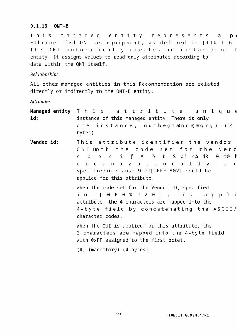
9.2.7 GAL Ethernet profile
This managed entity organizes data that describes the GTC adaptation layer processing functions of the ONT for Ethernet services. It is used with the GEM interworking termination point managed entity.
Instances of this managed entity are created and deleted on request of the OLT.
Relationships
An instance of this managed entity may be associated with zero or more instances of the GEM interworking termination point managed entity.
Attributes
Managed entity id: This attribute uniquely identifies each instance of this managed entity. (R, Set-by-create) (mandatory) (2 bytes)
Maximum GEM payload size:
This attribute defines the maximum payload size generated in the associated GEM interworking termination point managed entity. (R, W, Set-by-create) (mandatory) (2 bytes)
Actions
Create, delete, get, set
Notifications
None.
9.2.8 GAL Ethernet performance monitoring history data
This managed entity collects performance monitoring data associated with a GEM interworking termination point when the GEM layer provides Ethernet service. Instances of this managed entity are created and deleted by the OLT.
For a complete discussion of generic PM architecture, refer to clause I.1.9.
Relationships
An instance of this managed entity is associated with an instance of the GEM interworking termination point managed entity.
Attributes
Managed entity id: This attribute uniquely identifies each instance of this managed entity. Through an identical ID, this managed entity is implicitly linked to an instance of the GEM interworking TP. (R, Set-by-create) (mandatory) (2 bytes)
Interval end time: This attribute identifies the most recently finished 15-minute interval. (R) (mandatory) (1 byte)
TTAE.IT.G.984.4/R1118

Threshold data 1/2 id: This attribute points to an instance of the threshold data 1 managed entity that contains PM threshold values. Since no threshold value attribute number exceeds 7, a threshold data 2 ME is optional. (R, W, Set-by-create) (mandatory) (2 bytes)
Discarded frames: This attribute counts the number of downstream GEM frames discarded for any reason (erroneous FCS, too long, buffer overflow, etc.). (R) (mandatory) (4 bytes)
Actions
Create, delete, get, set
Get current data (optional)
Notifications
Threshold crossing alert
Number Threshold crossing alert Threshold value attribute # (Note)
0 Discarded frames 1
NOTE – This number associates the TCA with the specified threshold value attribute of the
threshold data 1 managed entity.
9.2.9 GAL TDM profile
This managed entity organizes data that describes the GTC adaptation layer processing functions of the ONT for TDM services. [ITU-T G.984.3] explains that the GEM adaptation layer generates a 125 s GEM frame that accommodates TDM traffic. The length of the TDM partition in the GEM frame depends on the TDM UNI bit rate. The clock recovery function and structured data transfer function are not necessary because the GEM is terminated in the PON section.
The receiver of the GEM adaptation layer should check for loss of GEM frame once every 125 s.
This managed entity is created and deleted on request of the OLT.
Relationships
An instance of this managed entity may be associated with zero or more instances of the GEM interworking termination point managed entity.
Attributes
TTAE.IT.G.984.4/R1119

Managed entity id: This attribute uniquely identifies each instance of this managed entity. (R, Set-by-create) (mandatory) (2 bytes)
GEM frame loss integration period:
This attribute is the GEM frame loss integration period in milliseconds. If GEM frame loss persists for this period, the GEM interworking termination point managed entity associated with this entity generates a GEM frame starvation alarm. (R, W, Set-by-create) (mandatory) (2 bytes)
Actions
Create, delete, get, set
Notifications
None
9.2.10 GAL TDM performance monitoring history data
This managed entity collects performance monitoring data from segmentation and reassembly (SAR) and convergence sublayer (CS) levels of a GEM interworking termination point that supports GAL TDM.
Instances of this managed entity are created and deleted on request of the OLT.
For a complete discussion of generic PM architecture, refer to clause I.1.9.
Relationships
One instance of this managed entity may exist for each instance of the GEM interworking termination point managed entity that represents GAL TDM functions.
Attributes
Managed entity id: This attribute uniquely identifies each instance of this managed entity. Through an identical ID, this managed entity is implicitly linked to an instance of the GEM interworking termination point ME. (R, Set-by-create) (mandatory) (2 bytes)
Interval end time: This attribute identifies the most recently finished 15-minute interval. (R) (mandatory) (1 byte)
TTAE.IT.G.984.4/R1120

Threshold data 1/2 id:
This attribute points to an instance of the threshold data 1 managed entity that contains PM threshold values. Since no threshold value attribute number exceeds 7, a threshold data 2 ME is optional. (R, W, Set-by-create) (mandatory) (2 bytes)
GEM frame loss: This attribute counts the number of lost GEM frames. It records the number of GEM frames detected as lost in the network prior to the destination interworking function GTC adaptation layer processing. (R) (mandatory) (4 bytes)
Buffer underflows: This attribute counts the number of times the reassembly buffer underflows. In the case of continuous underflow caused by a loss of GEM frame flow, a single buffer underflow should be counted. If the interworking function is implemented with multiple buffers, such as a cell level buffer and a bit level buffer, then either buffer underflow causes this count to be incremented. (R) (mandatory) (4 bytes)
Buffer overflows: This attribute counts the number of times the reassembly buffer overflows. If the interworking function is implemented with multiple buffers, such as a cell level buffer and a bit level buffer, then either buffer overflow causes this count to be incremented. (R) (mandatory) (4 bytes)
Actions
Create, delete, get, set
Get current data (optional)
Notifications
Threshold crossing alert
Number Threshold crossing alert Threshold value attribute # (Note)
0 GEM frame loss 1
1 Buffer underflows 2
2 Buffer overflows 3
NOTE – This number associates the TCA with the specified threshold value attribute of the
threshold data 1 managed entity.
9.2.11 FEC performance monitoring history data
This managed entity collects performance monitoring data associated with FEC counters. Instances of this managed entity are created and deleted by the OLT.
For a complete discussion of generic PM architecture, refer to clause I.1.9.
TTAE.IT.G.984.4/R1121

Relationships
An instance of this managed entity is associated with an instance of the ANI-G managed entity.
Attributes
Managed entity id: This attribute uniquely identifies each instance of this managed entity. Through an identical ID, this managed entity is implicitly linked to an instance of the ANI-G. (R, Set-by-create) (mandatory) (2 bytes)
Interval end time: This attribute identifies the most recently finished 15-minute interval. (R) (mandatory) (1 byte)
Threshold data 1/2 id: This attribute points to an instance of the threshold data 1 managed entity that contains PM threshold values. Since no threshold value attribute number exceeds 7, a threshold data 2 ME is optional. (R, W, Set-by-create) (mandatory) (2 bytes)
Corrected bytes: This attribute counts the number of bytes that were corrected by the FEC function. (R) (mandatory) (4 bytes)
Corrected code words: This attribute counts the code words that were corrected by the FEC function. (R) (mandatory) (4 bytes)
Uncorrectable code words: This attribute counts the code words that were not corrected by the FEC function. (R) (mandatory) (4 bytes)
Total code words: This attribute counts the total received code words. (R) (mandatory) (4 bytes)
FEC seconds: This attribute counts seconds during which there was a forward error correction anomaly. (R) (mandatory) (2 bytes)
Actions
Create, delete, get, set
Get current data (optional)
Notifications
Threshold crossing alert
Number Threshold crossing alert Threshold value attribute # (Note)
0 Corrected bytes 1
1 Corrected code words 2
2 Uncorrectable code words 3
TTAE.IT.G.984.4/R1122

3 Reserved
4 FEC seconds 4
NOTE – This number associates the TCA with the specified threshold value attribute of the
threshold data 1 managed entity.
9.3 Layer 2 data services
As outlined in Figure 9.3-1, this clause describes managed entities that support layer 2 services, independent of the exact nature of the interface (e.g., Ethernet, MoCA, xDSL). Possible interfaces are described in their own clauses.
9.3.13: Extended VLAN tagging operation config data
9.3.1: MAC bridge service profile
9.3.2: MAC bridge configuration data
9.3.3: MAC bridge PM history data
9.3.4: MAC bridge port config data
9.3.5: MAC bridge port designation data
9.3.9: MAC bridge port PM history data
9.3.10: 802.1p mapper service profile
9.3.6: MAC bridge port filter table data
9.3.11: VLAN tagging filter data
9.3.7: MAC bridge port filter preassign table
9.3.12: VLAN tagging operation config data
9.3.8: MAC bridge port bridge table data
Points to:TPOutbound TDInbound TD
Common TP
UNI, IW TP or IP
host
UNI, IW TP or IP
host
Interwork TP 0..7
Pointed to by:GEM interworking TPMulticast GEM interworking TP
Implicit links:VLAN tagging filter data
Pointed to by:Extended VLAN tagging operation config dataIP port config dataVLAN tagging operation config data
N
9.3.14: Dot1x port extension package
UNI
9.3.15: Dot1x configuration profile
9.3.16: Dot1x PM history data UNI
9.3.17: Radius PM history data
Ethernet frame PM history data
9.3.30: upstream9.3.31: downstream
Figure 9.3-1 – Managed entities that support layer 2
9.3.1 MAC bridge service profile
This managed entity models a MAC bridge in its entirety; any number of ports may then be associated with the bridge through pointers to the MAC bridge service profile managed entity. Instances of this managed entity are created and deleted by the OLT.
Relationships
Bridge ports are modelled by MAC bridge port configuration data managed entities, any number of which can point to a MAC bridge service profile. The real-time status of the bridge is available from an implicitly linked MAC bridge configuration data ME.
Attributes
TTAE.IT.G.984.4/R1123

Managed entity id: This attribute uniquely identifies each instance of this managed entity. The first byte is the slot id (defined in clause 9.1.5). If the UNI is integrated, this value is 0. The second byte is the bridge group id. (R, Set-by-create) (mandatory) (2 bytes)
Spanning tree ind: The Boolean value true specifies that the spanning tree algorithm is enabled. The value false disables spanning tree. (R, W, Set-by-create) (mandatory) (1 byte)
Learning ind: The Boolean value true specifies that bridge learning functions are enabled. The value false disables bridge learning. (R, W, Set-by-create) (mandatory) (1 byte)
Port bridging ind: The Boolean value true specifies that bridging between UNI ports is enabled. The value false disables local bridging. (R, W, Set-by-create) (mandatory) (1 byte)
Priority: This attribute specifies the bridge priority in the range 0..65535. The value of this attribute is copied to the bridge priority attribute of the associated MAC bridge configuration data managed entity. (R, W, Set-by-create) (mandatory) (2 bytes)
Max age: This attribute specifies the maximum age (in 256ths of a second) of received protocol information before its entry in the spanning tree listing is discarded. The range is 0x0600 to 0x2800 (6..40 seconds) in accordance with [IEEE 802.1D]. (R, W, Set-by-create) (mandatory) (2 bytes)
Hello time: This attribute specifies how often (in 256ths of a second) the bridge advertises its presence via hello packets while as a root or attempting to become a root. The range is 0x0100 to 0x0a00 (1..10 seconds) in accordance with [IEEE 802.1D]. (R, W, Set-by-create) (mandatory) (2 bytes)
Forward delay: This attribute specifies the forwarding delay (in 256ths of a second) when the bridge acts as the root. The range is 0x0400 to 0x1e00 (4..30 seconds) in accordance with [IEEE 802.1D]. (R, W, Set-by-create) (mandatory) (2 bytes)
Unknown MAC address discard:
The Boolean value true specifies that MAC frames with unknown destination addresses be discarded. The value false specifies that such frames be forwarded to all allowed ports. (R, W, Set-by-create) (mandatory) (1 byte)
TTAE.IT.G.984.4/R1124

MAC learning depth: This attribute specifies the maximum number of UNI MAC addresses to be learned by the bridge. The default value 0 specifies that there is no administratively-imposed limit. (R, W, Set-by-create) (optional) (1 byte)
Dynamic filtering ageing time:
This attribute specifies the age of dynamic filtering entries in the bridge database, after which unrefreshed entries are discarded. In accordance with [IEEE 802.1D] clause 7.9.2 and [IEEE 802.1Q] clause 8.8.3, the range is 10..1 000 000 seconds, with a resolution of 1 second and a default of 300 seconds. (R, W, Set-by-create) (optional) (4 bytes)
Actions
Create, delete, get, set
Notifications
None.
9.3.2 MAC bridge configuration data
This managed entity organizes status data associated with a MAC bridge. The ONT automatically creates or deletes an instance of this managed entity upon the creation or deletion of a MAC bridge service profile.
Relationships
This managed entity is associated with one instance of a MAC bridge service profile.
Attributes
Managed entity id: This attribute uniquely identifies each instance of this managed entity. Through an identical ID, this managed entity is implicitly linked to an instance of the MAC bridge service profile. (R) (mandatory) (2 bytes)
Bridge MAC address: This attribute indicates the MAC address used by the bridge. The ONT sets this attribute to the value programmed into the ONT. (R) (mandatory) (6 bytes)
Bridge priority: This attribute reports the priority of the bridge. The ONT copies this attribute from the priority attribute of the associated MAC bridge service profile. The value of this attribute changes with updates to the MAC bridge service profile priority attribute. (R) (mandatory) (2 bytes)
Designated root: This attribute identifies the bridge at the root of the spanning
TTAE.IT.G.984.4/R1125

tree. It comprises bridge priority (2 bytes) and MAC address (6 bytes). (R) (mandatory) (8 bytes)
Root path cost: This attribute reports the cost of the best path to the root as seen from the bridge. Upon ME instantiation, the ONT sets this attribute to 0. (R) (mandatory) (4 bytes)
Bridge port count: This attribute records the number of ports linked to this bridge. (R) (mandatory) (1 byte)
Root port num: This attribute contains the port number that has the lowest cost from the bridge to the root bridge. The value 0 means that this bridge is itself the root. Upon ME instantiation, the ONT sets this attribute to 0. (R) (mandatory) (2 bytes)
Hello time: This attribute is the hello time received from the designated root, the interval (in 256ths of a second) between hello packets. Its range is 0x0100 to 0x0a00 (1..10 seconds) in accordance with [IEEE 802.1D]. (R) (optional) (2 bytes)
Forward delay: This attribute is the forwarding delay time received from the designated root (in 256ths of a second). Its range is 0x0400 to 0x1e00 (4..30 seconds) in accordance with [IEEE 802.1D]. (R) (optional) (2 bytes)
Actions
Get, set
Notifications
None.
9.3.3 MAC bridge performance monitoring history data
This managed entity collects performance monitoring data associated with a MAC bridge. Instances of this managed entity are created and deleted by the OLT.
For a complete discussion of generic PM architecture, refer to clause I.1.9.
Relationships
This managed entity is associated with one instance of a MAC bridge service profile.
Attributes
Managed entity id: This attribute uniquely identifies each instance of this managed entity. Through an identical ID, this managed entity is implicitly linked to an instance of the MAC bridge service profile. (R, Set-by-create) (mandatory) (2 bytes)
TTAE.IT.G.984.4/R1126

Interval end time: This attribute identifies the most recently finished 15-minute interval. (R) (mandatory) (1 byte)
Threshold data 1/2 id: This attribute points to an instance of the threshold data 1 managed entity that contains PM threshold values. Since no threshold value attribute number exceeds 7, a threshold data 2 ME is optional. (R, W, Set-by-create) (mandatory) (2 bytes)
Bridge learning entry discard count:
This attribute counts forwarding database entries that have been or would have been learned but were discarded or replaced due to lack of space in the database table. When used with the MAC learning depth attribute of the MAC bridge service profile, the bridge learning entry discard count may be particularly useful in detecting MAC spoofing attempts. (R) (mandatory) (4 bytes)
Actions
Create, delete, get
Get current data (optional)
Notifications
Threshold crossing alert
Number Threshold crossing alert Threshold value attribute # (Note)
0 Bridge learning entry discard 1
NOTE – This number associates the TCA with the specified threshold value attribute of the
threshold data 1 managed entity.
9.3.4 MAC bridge port configuration data
This managed entity models a port on a MAC bridge. Instances of this managed entity are created and deleted by the OLT.
Relationships
An instance of this managed entity is linked to an instance of the MAC bridge service profile. Additional bridge port control capabilities are provided by implicitly linked instances of some or all of:
• MAC bridge port filter table data.
• MAC bridge port filter preassign table.
• VLAN tagging filter data.
• Extended VLAN tagging operation config data.
Real-time status of the bridge port is provided by implicitly linked instances of:
TTAE.IT.G.984.4/R1127

• MAC bridge port designation data.
• MAC bridge port bridge table data.
Attributes
Managed entity id: This attribute uniquely identifies each instance of this managed entity. (R, Set-by-create) (mandatory) (2 bytes)
Bridge id pointer: This attribute points to an instance of the MAC bridge service profile. (R, W, Set-by-create) (mandatory) (2 bytes)
Port num: This attribute is the bridge port number. It must be unique among all ports associated with a particular MAC bridge service profile. (R, W, Set-by-create) (mandatory) (1 byte)
TP type: This attribute identifies the type of termination point associated with this MAC bridge port. Valid values are:
1 Physical path termination point Ethernet UNI2 Interworking VCC termination point3 802.1p mapper service profile4 IP host config data5 GEM interworking termination point6 Multicast GEM interworking termination point7 Physical path termination point xDSL UNI part 18 Physical path termination point VDSL UNI9 Ethernet flow termination point10 Physical path termination point 802.11 UNI11 Virtual Ethernet interface point
(R, W, Set-by-create) (mandatory) (1 byte)
TP pointer: This attribute points to the termination point associated with this MAC bridge port. The TP type attribute indicates the type of the termination point; this attribute contains its instance identifier (ME ID).
NOTE – When the TP type is VDSL or xDSL, the two most significant bits may be used to indicate a bearer channel.
(R, W, Set-by-create) (mandatory) (2 bytes)
TTAE.IT.G.984.4/R1128

Port priority: This attribute denotes the priority of the port. The range is 0..255. (R, W, Set-by-create) (optional in GEM mode) (2 bytes)
Port path cost: This attribute specifies the contribution of the port to the path cost toward the spanning tree root bridge. The range is 1..65535. (R, W, Set-by-create) (mandatory) (2 bytes)
Port spanning tree ind:
The Boolean value true enables STP LAN topology change detection at this port. The value false disables topology change detection. (R, W, Set-by-create) (mandatory) (1 byte)
Encapsulation method:
This attribute is not used. If it is present, it should be set to 1. (R, W, Set-by-create) (optional) (1 byte)
LAN FCS ind: This attribute indicates whether frame check sequence bytes are forwarded (0) or discarded (1). It is not expected to be needed in G-PON applications, but is retained for backward compatibility. The setting applies in both directions of transmission, and applies regardless of encapsulation method, but it is meaningful only for ports on the ANI side of the MAC bridge. The default value of this attribute is 0. (R, W, Set-by-create) (1 byte) (optional)
Port MAC address: If the termination point associated with this port has a MAC address, this attribute specifies it. (R) (optional) (6 bytes)
Outbound TD pointer:
This attribute points to a traffic descriptor that limits the traffic rate leaving the MAC bridge. (R, W) (optional) (2 bytes)
Inbound TD pointer:
This attribute points to a traffic descriptor that limits the traffic rate entering the MAC bridge. (R, W) (optional) (2 bytes)
MAC learning depth:
This attribute specifies the maximum number of MAC addresses to be learned by this MAC bridge port. The default value 0 specifies that there is no administratively-imposed limit. (R, W, Set-by-create) (optional) (1 byte)
NOTE 1 – If this attribute is not zero, its value overrides the value set in the MAC learning depth attribute of the MAC bridge service profile.
Actions
Create, delete, get, set
Notifications
TTAE.IT.G.984.4/R1129

Alarm
Number Alarm Description
0 Port blocking This port has been blocked due to loop detection in
accordance with IEEE 802.1D
1..207 Reserved
208..223 Vendor-specific alarms Not to be standardized
NOTE 2 – To determine the state of a MAC bridge port, the OLT can read the port state attribute of
the MAC bridge port designation data.
9.3.5 MAC bridge port designation data
This managed entity records data associated with a bridge port. The ONT automatically creates or deletes an instance of this managed entity upon the creation or deletion of a MAC bridge port configuration data ME.
Relationships
An instance of this managed entity is associated with one MAC bridge port configuration data ME.
Attributes
Managed entity id: This attribute uniquely identifies each instance of this managed entity. Through an identical ID, this managed entity is implicitly linked to an instance of the MAC bridge port configuration data. (R) (mandatory) (2 bytes)
TTAE.IT.G.984.4/R1130

Designated bridge root cost port:
This attribute contains the designated root, designated cost, designated bridge and designated port, which are some of the outputs of the read port parameters operation defined in clause 14.8.2.1 of [IEEE 802.1D]:
• Identifier of the designated bridge for the port's segment (8 bytes).
• Bridge identifier of the root transmitted by the designated bridge for the segment (8 bytes).
• Port number of the designated port on the designated bridge considered to be part of this port's segment (4 bytes).
• Path cost contribution of the designated port to this port's segment (4 bytes).
Upon ME instantiation, the ONT sets this attribute to 0. (R) (mandatory) (24 bytes)
Port state: This attribute provides status information on the port. Valid values include:
0 Disabled.1 Listening.2 Learning.3 Forwarding.4 Blocking.5 Linkdown.6 Stp_off.
in accordance with [IEEE 802.1D]. (R) (mandatory) (1 byte)
NOTE – The value linkdown is introduced to denote the port status when the Ethernet link state is down. This value distinguishes the case where Ethernet is physically down from the case where Ethernet is administratively down, the latter being denoted by disabled.
The value stp_off is introduced to denote the port status where spanning tree protocol is disabled by setting the port spanning tree ind attribute of the MAC bridge port configuration data to false, and the Ethernet link state is up. This value distinguishes whether or not frame forwarding is under control of STP.
Actions
TTAE.IT.G.984.4/R1131

Get, Set table
Notifications
None.
9.3.6 MAC bridge port filter table data
This managed entity organizes data associated with a bridge port. The ONT automatically creates or deletes an instance of this managed entity upon the creation or deletion of a MAC bridge port configuration data managed entity.
NOTE – The OLT should disable learning mode in the MAC bridge service profile before writing to the MAC filter table.
Relationships
An instance of this managed entity is associated with an instance of a MAC bridge port configuration data managed entity.
Attributes
Managed entity id: This attribute uniquely identifies each instance of this managed entity. Through an identical ID, this managed entity is implicitly linked to an instance of the MAC bridge port configuration data ME. (R) (mandatory) (2 bytes)
MAC filter table: This attribute lists MAC destination addresses associated with the bridge port, each with an allow/disallow forwarding indicator for traffic flowing out of the bridge port. In this way, the upstream traffic is filtered on the ANI-side bridge ports, and the downstream traffic is filtered on the UNI-side bridge ports. Each entry contains:
• The entry number, an index into this attribute list (1 byte).
• Filter byte (1 byte).
• MAC address (6 bytes).
The bits of the filter byte are assigned as follows:
Bit Name Setting
1 (LSB) Filter/forward 0: forward1: filter
2..7 Reserved 08 Add/remove 0: remove this entry (set operation)
1: add this entry
TTAE.IT.G.984.4/R1132

Upon ME instantiation, the ONT sets this attribute to an empty table.
One OMCI set message can convey a maximum of three table entries. However, OMCI does not provide robust exception handling when more than one entry is included in a set command, and multiple entries per set operation are not recommended.
(R, W) (mandatory) (8N bytes, where N is the number of entries in the list)
Actions
Get, get next, set
Notifications
None.
9.3.7 MAC bridge port filter preassign table
This managed entity provides an alternate approach to address filtering from that supported through MAC bridge port filter table data. This alternate approach is useful when all groups of addresses are stored beforehand in the ONT, and this managed entity designates which groups are valid or invalid for filtering. On a circuit pack in which all groups of addresses are preassigned and stored locally, the ONT creates or deletes an instance of this managed entity automatically upon creation or deletion of a MAC bridge port configuration data ME.
Relationships
An instance of this managed entity is associated with an instance of a MAC bridge port configuration data managed entity.
Attributes
Managed entity id: This attribute uniquely identifies each instance of this managed entity. Through an identical ID, this managed entity is implicitly linked to an instance of the MAC bridge port configuration data ME. (R) (mandatory) (2 bytes)
The following ten attributes have similar definitions. Each permits the OLT to specify whether MAC addresses or Ethertypes of the named type are forwarded (0) or filtered (1). In each case, the initial value of the attribute is 0.
# Protocol MAC address Ethertype Standard
1 IPv4 multicast 01.00.5E.00.00.00 – – [b-IETF RFC 1700]
TTAE.IT.G.984.4/R1133

# Protocol MAC address Ethertype Standard
01.00.5E.7F.FF.FF
2 IPv6 multicast 33.33.00.00.00.00 –
33.33.FF.FF.FF.FF
– [b-IETF RFC 2464]
3 IPv4 broadcast FF.FF.FF.FF.FF.FF 0x0800 [b-IETF RFC 1700]
4 RARP FF.FF.FF.FF.FF.FF 0x8035 [b-IETF RFC 1700]
5 IPX FF.FF.FF.FF.FF.FF 0x8137 [b-IETF RFC 1700]
09.00.1B.FF.FF.FF,
09.00.4E.00.00.02
–
6 NetBEUI 03.00.00.00.00.01 –
7 AppleTalk FF.FF.FF.FF.FF.FF 0x809B,
0x80F3
[b-IETF RFC 1700]
09.00.07.00.00.00 –
09.00.07.00.00.FC,
09.00.07.FF.FF.FF
–
8 Bridge
management
information
01.80.C2.00.00.00 –
01.80.C2.00.00.FF
– [IEEE 802.1D]
9 ARP FF.FF.FF.FF.FF.FF 0x0806 [b-IETF RFC 1700]
10 PPPoE broadcast FF.FF.FF.FF.FF.FF 0x8863 [b-IETF RFC 2516]
IPv4 multicast filtering: (R, W) (mandatory) (1 byte)
IPv6 multicast filtering: (R, W) (mandatory) (1 byte)
IPv4 broadcast filtering: (R, W) (mandatory) (1 byte)
RARP filtering: (R, W) (mandatory) (1 byte)
IPX filtering: (R, W) (mandatory) (1 byte)
NetBEUI filtering: (R, W) (mandatory) (1 byte)
AppleTalk filtering: (R, W) (mandatory) (1 byte)
TTAE.IT.G.984.4/R1134

Bridge management information filtering:
(R, W) (mandatory) (1 byte)
Note that some MAC addresses should not be handled, considering the following rules of [IEEE 802.1D]:
1 Addresses from 01.80.C2.00.00.00 to 01.80.C2.00.00.0F are reserved.
2 Addresses from 01.80.C2.00.00.20 to 01.80.C2.00.02.0F are used for GARP application addresses.
ARP filtering: (R, W) (mandatory) (1 byte)
PPPoE filtering: (R, W) (mandatory) (1 byte)
Actions
Get, set
Notifications
None.
9.3.8 MAC bridge port bridge table data
This managed entity reports status data associated with a bridge port. The ONT automatically creates or deletes an instance of this managed entity upon the creation or deletion of a MAC bridge port configuration data.
Relationships
An instance of this managed entity is associated with an instance of a MAC bridge port configuration data managed entity.
Attributes
Managed entity id: This attribute uniquely identifies each instance of this managed entity. Through an identical ID, this managed entity is implicitly linked to an instance of the MAC bridge port configuration data ME. (R) (mandatory) (2 bytes)
Bridge table: This attribute lists known MAC destination addresses, whether they are learned or statically assigned, whether packets having them as destination addresses are filtered or forwarded, and their ages. Each entry contains:
• Information (2 bytes).
• MAC address (6 bytes).
TTAE.IT.G.984.4/R1135

The information bits are assigned as described below.
Bit Name Setting
1 (LSB) Filter/forward 0: forward1: filter
2 Reserved 0
3 Dynamic/static 0: this entry is statically assigned
1: this entry is dynamically learned
4 Reserved 0
16..5 Age Age in seconds (1..4095)
Upon ME instantiation, this attribute is an empty list. (R) (mandatory) (8M bytes, where M is the number of entries in the list)
Actions
Get, get next
Notifications
None.
9.3.9 MAC bridge port performance monitoring history data
This managed entity collects performance monitoring data associated with a MAC bridge port. Instances of this managed entity are created and deleted by the OLT.
For a complete discussion of generic PM architecture, refer to clause I.1.9.
Relationships
An instance of this managed entity is associated with an instance of a MAC bridge port configuration data managed entity.
Attributes
Managed entity id: This attribute uniquely identifies each instance of this managed entity. Through an identical ID, this managed entity is implicitly linked to an instance of the MAC bridge port configuration data ME. (R, Set-by-create) (mandatory) (2 bytes)
Interval end time: This attribute identifies the most recently finished 15-minute interval. (R) (mandatory) (1 byte)
TTAE.IT.G.984.4/R1136

Threshold data 1/2 id: This attribute points to an instance of the threshold data 1 managed entity that contains PM threshold values. Since no threshold value attribute number exceeds 7, a threshold data 2 ME is optional. (R, W, Set-by-create) (mandatory) (2 bytes)
Forwarded frame counter: This attribute counts frames transmitted successfully on this port. (R) (mandatory) (4 bytes)
Delay exceeded discard counter:
This attribute counts frames discarded on this port because transmission was delayed. (R) (mandatory) (4 bytes)
MTU exceeded discard counter:
This attribute counts frames discarded on this port because the MTU was exceeded. (R) (mandatory) (4 bytes)
Received frame counter: This attribute counts frames received on this port. (R) (mandatory) (4 bytes)
Received and discarded counter:
This attribute counts frames received on this port that were discarded due to errors. (R) (mandatory) (4 bytes)
Actions
Create, delete, get, set
Get current data (optional)
Notifications
Threshold crossing alert
Number Threshold crossing alert Threshold value attribute # (Note)
0 Reserved
1 Delay exceeded discard 1
2 MTU exceeded discard 2
3 Reserved
4 Received and discarded 3
NOTE – This number associates the TCA with the specified threshold value attribute of the
threshold data 1 managed entity.
9.3.10 802.1p mapper service profile
This managed entity associates the priorities of 802.1P priority tagged frames with specific connections. The operation of this managed entity affects only upstream traffic. Instances of this managed entity are created and deleted by the OLT.
Relationships
TTAE.IT.G.984.4/R1137

At its root, an instance of this ME may be associated with zero or one instance of a PPTP UNI, MAC bridge port configuration data, or any type of interworking termination point ME that carries IEEE 802 traffic. Each of its eight branches is associated with zero or one GEM interworking termination point.
Attributes
Managed entity id: This attribute uniquely identifies each instance of this managed entity. (R, Set-by-create) (mandatory) (2 bytes)
TP pointer: This attribute points to an instance of the associated termination point. The termination point type is determined by the TP type attribute:
TP type TP pointer points to…
0 Bridging mapping. Pointer should be set to 0xFFFF by OLT and ignored by ONT.
1 PPTP Ethernet UNI2 IP host config data3 Ethernet flow TP4 PPTP xDSL UNI5 PPTP 802.11 UNI6 PPTP MoCA UNI7 Virtual Ethernet interface point8 Interworking VCC termination point
Not supported: Bridging mapping if TP pointer value is 0xFFFF. TP pointer may also point to PPTP Ethernet UNI.
NOTE – When the TP type is xDSL, the two most significant bits
may be used to indicate a bearer channel.
(R, W, Set-by-create) (mandatory) (2 bytes)
TP type: This attribute identifies the type of termination point associated with the mapper.
0 Mapper used for bridging-mapping1 Mapper directly associated with a PPTP Ethernet UNI2 Mapper directly associated with an IP host service3 Mapper directly associated with an Ethernet flow
termination point4 Mapper directly associated with a PPTP xDSL UNI5 Mapper directly associated with a PPTP 802.11 UNI6 Mapper directly associated with a PPTP MoCA UNI
TTAE.IT.G.984.4/R1138

7 Mapper directly associated with a virtual Ethernet interface point8 Mapper directly associated with an interworking VCC
termination point
(R, W, Set-by-create) (optional) (1 byte)
Interwork TP pointer for P-bit priority 0:
(R, W, Set-by-create) (mandatory) (2 bytes)
Interwork TP pointer for P-bit priority 1:
(R, W, Set-by-create) (mandatory) (2 bytes)
Interwork TP pointer for P-bit priority 2:
(R, W, Set-by-create) (mandatory) (2 bytes)
Interwork TP pointer for P-bit priority 3:
(R, W, Set-by-create) (mandatory) (2 bytes)
Interwork TP pointer for P-bit priority 4:
(R, W, Set-by-create) (mandatory) (2 bytes)
Interwork TP pointer for P-bit priority 5:
(R, W, Set-by-create) (mandatory) (2 bytes)
Interwork TP pointer for P-bit priority 6:
(R, W, Set-by-create) (mandatory) (2 bytes)
Interwork TP pointer for P-bit priority 7:
(R, W, Set-by-create) (mandatory) (2 bytes)
Unmarked frame option: This attribute specifies how the ONT should handle untagged Ethernet frames received across the associated interface. Although it does not alter the frame in any way, the ONT routes the frame as if it were tagged with P bits (PCP field) according to the following code points.
0 Derive implied PCP field from DSCP bits of received frame
1 Set implied PCP field to fixed value specified by default P-bit marking attribute
(R, W, Set-by-create) (mandatory) (1 byte)
Untagged downstream frames are passed through the mapper transparently.
DSCP to P-bit mapping: This attribute is valid when the unmarked frame option attribute is set to 0. The DSCP to P-bit attribute can be considered a bit
TTAE.IT.G.984.4/R1139

string sequence of 64 3-bit groupings. The 64 sequence entries represent the possible values of the 6-bit DSCP field. Each 3-bit grouping specifies the P-bit value to which the associated DSCP value should be mapped. The unmarked frame is then directed to the GEM interworking termination point indicated by the interwork TP pointer mappings. (R, W) (mandatory) (24 bytes)
NOTE 2 – If certain bits in the DSCP field are to be ignored in the mapping process, the attribute should be provisioned such that all possible values of those bits produce the same P-bit mapping. This can be applied to the case where instead of full DSCP, the operator wishes to adopt the priority mechanism based on IP precedence, which needs only the three MSBs of the DSCP field.
Default P-bit marking: This attribute is valid when the unmarked frame option attribute is set to 1. In its least significant bits, the default P-bit marking attribute contains the default PCP field to be assumed. The unmodified frame is then directed to the GEM interworking termination point indicated by the interwork TP pointer mappings. (R, W, Set-by-create) (mandatory) (1 byte)
TP type: This attribute identifies the type of termination point associated with the mapper.0 Mapper used for bridging-mapping.1 Mapper directly associated with a PPTP Ethernet UNI.2 Mapper directly associated with an IP host service.3 Mapper directly associated with an Ethernet flow termination point.4 Mapper directly associated with a PPTP xDSL UNI.5 Mapper directly associated with a PPTP 802.11 UNI.6 Mapper directly associated with a PPTP MoCA UNI.
(R, W, Set-by-create) (optional) (1 byte)
Actions
Create, delete, get, set
Notifications
None.
TTAE.IT.G.984.4/R1140

9.3.11 VLAN tagging filter data
This managed entity organizes data associated with VLAN tagging. Instances of this managed entity are created and deleted by the OLT.
Relationships
An instance of this managed entity is associated with an instance of a MAC bridge port configuration data managed entity. By definition, tag filtering occurs closer to the MAC bridge than the tagging operation. Schematically, the ordering of the functions is:
ANI – Tag_operation – Tag_filtering – Bridging – Tag_filtering – Tag_operation – UNI
Attributes
Managed entity id: This attribute uniquely identifies each instance of this managed entity. Through an identical ID, this managed entity is implicitly linked to an instance of the MAC bridge port configuration data ME. (R, Set-by-create) (mandatory) (2 bytes)
VLAN filter list: This attribute lists provisioned TCI values for the bridge port. A TCI value (consisting of user priority, CFI and VID) is represented by 2 bytes. 12 VLAN entries are supported. The first N are valid, where N is given by the number of entries attribute. (R, W, Set-by-create) (mandatory) (24 bytes)
Forward operation: When a frame passes through the MAC bridge port, it is processed according to the operation specified by the forward operation table. Figure 9.3.11-2 illustrates the treatment of frames according to the provisioned action possibilities. Tagged and untagged frames are treated separately, but both in accordance with the figure. While all forwarding operations are plausible, only actions 0x10 and 0x12 are necessary to construct a VLAN mapper and an 802.1p mapper, respectively. (R, W, Set-by-create) (mandatory) (1 byte)
Forward operation
Type of received frame
Tagged Untagged
0x00 Bridging (a) (no investigation) Bridging (a)
0x01 Discarding (c) Bridging (a)
0x02 Bridging (a) (no investigation) Discarding (c)
0x03 Action (h) (VID investigation) Bridging (a)
TTAE.IT.G.984.4/R1141

Forward operation
Type of received frame
Tagged Untagged
0x04 Action (h) (VID investigation) Discarding (c)
0x05 Action (g) (VID investigation) Bridging (a)
0x06 Action (g) (VID investigation) Discarding (c)
0x07 Action (h) (user priority investigation) Bridging (a)
0x08 Action (h) (user priority investigation) Discarding (c)
0x09 Action (g) (user priority investigation) Bridging (a)
0x0A Action (g) (user priority investigation) Discarding (c)
0x0B Action (h) (TCI investigation) Bridging (a)
0x0C Action (h) (TCI investigation) Discarding (c)
0x0D Action (g) (TCI investigation) Bridging (a)
0x0E Action (g) (TCI investigation) Discarding (c)
0x0F Action (h) (VID investigation) Bridging (a)
0x10 Action (h) (VID investigation) Discarding (c)
0x11 Action (h) (user priority investigation) Bridging (a)
0x12 Action (h) (user priority investigation) Discarding (c)
0x13 Action (h) (TCI investigation) Bridging (a)
0x14 Action (h) (TCI investigation) Discarding (c)
0x15 Bridging (a) (no investigation) Discarding (c)
0x16 Action (j) (VID investigation) Bridging (a)
0x17 Action (j) (VID investigation) Discarding (c)
0x18 Action (j) (user priority investigation) Bridging (a)
0x19 Action (j) (user priority investigation) Discarding (c)
0x1A Action (j) (TCI investigation) Bridging (a)
0x1B Action (j) (TCI investigation) Discarding (c)
0x1C Action (k) (VID investigation) Bridging (a)
0x1D Action (k) (VID investigation) Discarding (c)
0x1E Action (k) (user priority investigation) Bridging (a)
0x1F Action (k) (user priority investigation) Discarding (c)
0x20 Action (k) (TCI investigation) Bridging (a)
TTAE.IT.G.984.4/R1142

Forward operation
Type of received frame
Tagged Untagged
0x21 Action (k) (TCI investigation) Discarding (c)
The table contains duplicate entries due to simplification of the original set of actions.
This table and the actions are discussed in detail below.
Number of entries: This attribute specifies the number of valid entries in the VLAN filter list. (R, W, Set-by-create) (mandatory) (1 byte)
Actions
Create, delete, get, set
Notifications
None.
Supplementary explanation
This clause explains the actions specified in the forward operation attribute.
The format of an Ethernet frame for VLAN services is described in [IEEE 802.1Q]:
Figure 9.3.11-1 – Format of an Ethernet frame for VLAN services
a) Basic MAC bridge operation:
All frames are accepted into the MAC bridging entity. Egress frames are forwarded from this port if either: a) the frame's MAC destination address (DA) is listed in the MAC bridge port bridge table data for this port; or b) the frame's DA does not appear in the MAC bridge port bridge table data for any port (flooding). The content of the VLAN filter list attribute is not meaningful.
TTAE.IT.G.984.4/R1143

NOTE – Action (a) on a given port may imply egress flooding of a frame from other ports of the
bridge. The possible VLAN tagging filter data MEs attached to the other ports override this action;
however, so the frame is only transmitted from some other port if it also satisfies the forward operation
attribute value established on that port.
Figure 9.3.11-2 – Basic MAC bridge operation
Other possible actions are as follows:
c) Unconditional discarding:
Frames in both directions are unconditionally discarded without investigation of TCI or MAC address. This action can be used to discard all tagged traffic or all untagged traffic at the port of attachment, depending on the code point in the table. The content of the VLAN filter list attribute is not meaningful.
g) Negative filteringby TCI:
All frames are admitted into the bridging entity. If the specified fields in the TCI of a candidate egress frame match any entry in the VLAN filter list, the frame is not forwarded by this port. Otherwise, the frame is forwarded based on destination MAC address, according to action (a).
h) Positive filtering by All frames are admitted into the bridging entity. If the specified
TTAE.IT.G.984.4/R1144
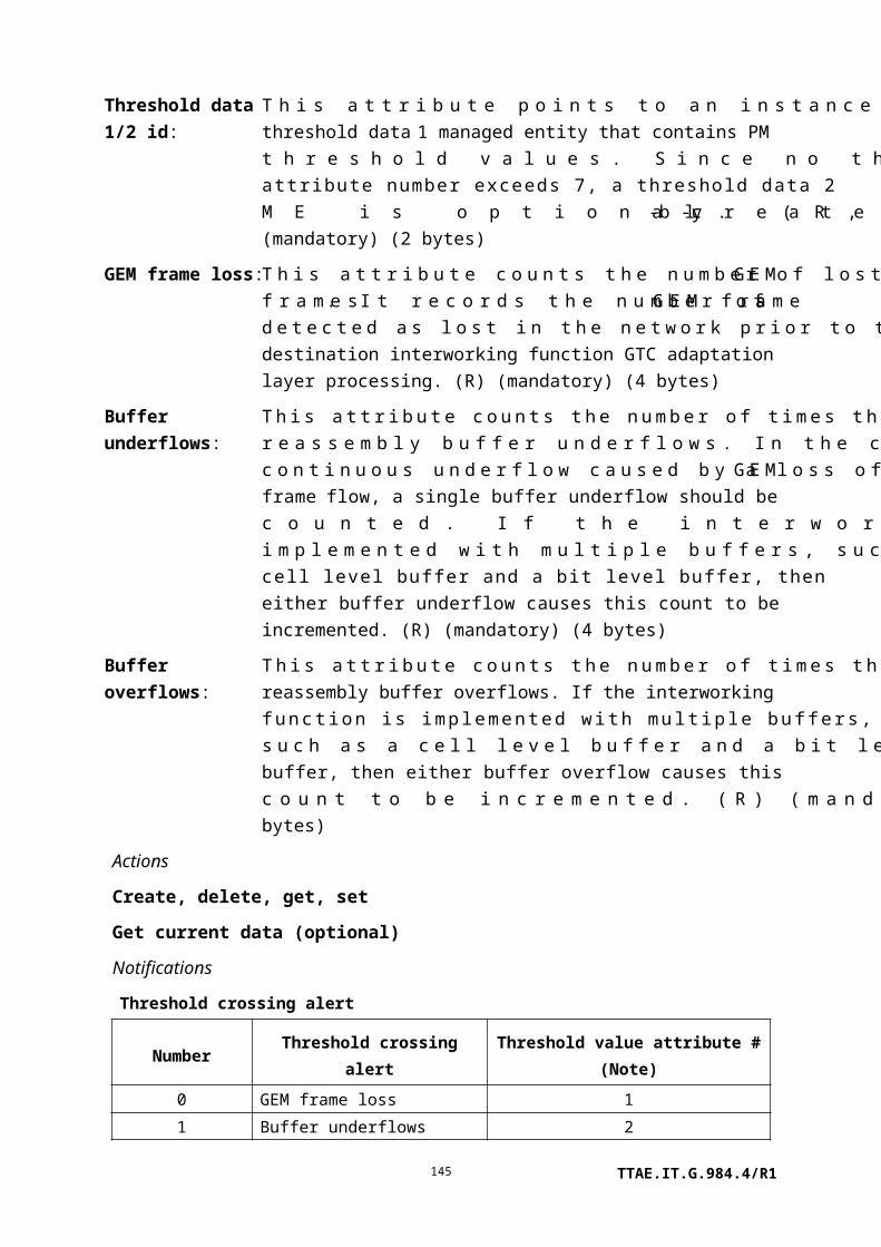
TCI and dropping for no match:
fields in the TCI of a candidate egress frame match any entry in the VLAN filter list, the frame is forwarded based on destination MAC address, according to action (a). If there is no match of the specified TCI fields, the frame is discarded.
j) Positive filtering by TCI and DA:
All frames are admitted into the bridging entity. If the specified fields in the TCI of a candidate egress frame match any entry in the VLAN filter list, the frame is forwarded based on destination MAC address. The frame is never flooded to this or other ports. If the specified TCI fields and DA do not both match, the frame is discarded.
k) Bidirectional positive filtering by TCI and dropping for no match:
Both ingress and egress frames are filtered on investigation of TCI fields. If the specified fields in the TCI of a candidate ingress/egress frames match any entry in the VLAN filter list, the frame is forwarded based on destination MAC address, according to action (a). If there is no match of the specified TCI fields, the frame is discarded.
Figure 9.3.11-3 – Positive filtering by TCI operation
NOTE – The phrase some or all refers to the parts or the entirety of the TCI field called out by the specific value provisioned into the forward operation attribute.
g) Negative filtering by TCI: If some or all of the fields in the TCI of the received frame are included in the VLAN filter list, it is not forwarded by this port. Otherwise, it is forwarded according to action a) as shown in Figure 9.3.11-4.
TTAE.IT.G.984.4/R1145

Figure 9.3.11-4 – Negative filtering by TCI operation
h) Positive filtering by TCI and dropping for no match:
If some or all of the fields in the TCI of the received frame are included in the VLAN filter list, it is forwarded according to action a) as shown in Figure 9.3.11-5. If its TCI is not accepted by any port on the bridge, the frame is discarded.
Figure 9.3.11-5 – Positive filtering by TCI operation, dropping for no match
9.3.12 VLAN tagging operation configuration data
This managed entity organizes data associated with VLAN tagging. Instances of this managed entity are created and deleted by the OLT.
Relationships
Zero or one instance of this managed entity may exist for an instance of any managed entity that can terminate or modify an Ethernet stream.
TTAE.IT.G.984.4/R1146

When this managed entity is associated with a UNI-side termination point, it performs its upstream classification and tagging operations before offering the upstream frame to other filtering, bridging or switching functions. In the downstream direction, the defined inverse operation is the last operation performed on the frame before offering it to the UNI-side termination.
When this managed entity is associated with an ANI-side termination point, it performs its upstream classification and tagging operations as the last step before queuing for transmission to the OLT, after having received the upstream frame from other filtering, bridging or switching functions. In the downstream direction, the defined inverse operation is the first operation performed on the frame before offering it to possible filter, bridge or switch functions.
Attributes
Managed entity id: This attribute uniquely identifies each instance of this managed entity. When the optional association type attribute is 0 or undefined, this attribute's value is the same as the id of the managed entity with which this VLAN tagging operation configuration data instance is associated, which may be either a PPTP Ethernet UNI or an IP host config data ME. Otherwise, the value of the ME ID is unconstrained except by the need to be unique. (R, Set-by-create) (mandatory) (2 bytes)
Upstream VLAN tagging operation mode:
This attribute controls upstream VLAN tagging. Valid values are:
0 Upstream frame is sent as is, regardless of tag.1 The upstream frame is tagged, whether or not the received
frame was tagged. The frame's TCI, consisting of VID, CFI and user priority, is attached or overwritten with the upstream VLAN tag TCI value.
2 The upstream frame is prepended with a tag, whether or not the received frame was tagged. If the received frame is tagged, a second tag (Q-in-Q) is added to the frame. If the received frame is not tagged, a tag is attached to the frame. The added tag is defined by the upstream VLAN tag TCI value attribute.
(R, W, Set-by-create) (mandatory) (1 byte)
Upstream VLAN tag TCI value:
This attribute specifies the TCI for upstream VLAN tagging. It is used when the upstream VLAN tagging operation mode is 1 or 2. (R, W, Set-by-create) (mandatory) (2 bytes)
TTAE.IT.G.984.4/R1147

Downstream VLAN tagging operation mode:
This attribute controls downstream VLAN tagging. Valid values are:
0 Downstream frame is sent as is, regardless of tag.1 If the received frame is tagged, the outer tag is stripped.
An untagged frame is forwarded unchanged.
(R, W, Set-by-create) (mandatory) (1 byte)
Association type: This attribute specifies the type of the ME that is associated with this VLAN tagging operation configuration data ME. Values are assigned in accordance with the following list:
0 (default) Physical path termination point Ethernet UNI (for backward compatibility, may also be an IP host config data ME; they must not have the same ME ID). The associated ME instance is implicit; its identifier is the same as that of this VLAN tagging operation configuration data.
1 IP host config data2 802.1p mapper service profile3 MAC bridge port configuration data4 Physical path termination point xDSL UNI5 GEM interworking termination point6 Multicast GEM interworking termination point7 Physical path termination point MoCA UNI8 Physical path termination point 802.11 UNI9 Ethernet flow termination point10 Physical path termination point Ethernet UNI11 Virtual Ethernet interface point
The associated ME instance is identified by the associated ME pointer. (R, W, Set-by-create) (optional) (1 byte)
Associated ME pointer: When the association type attribute is non-zero, this attribute points to the ME with which this VLAN tagging operation configuration data ME is associated. Otherwise, this attribute is undefined, and the association is implicit.
NOTE – When the association type is xDSL, the two most significant bits may be used to indicate a bearer channel.
(R, W, Set-by-create) (optional) (2 bytes)
Actions
TTAE.IT.G.984.4/R1148

Create, delete, get, set
Notifications
None.
9.3.13 Extended VLAN tagging operation configuration data
This managed entity organizes data associated with VLAN tagging. Regardless of its point of attachment, the specified tagging operations refer to the upstream direction. Instances of this managed entity are created and deleted by the OLT.
Relationships
Zero or one instance of this managed entity may exist for an instance of any managed entity that can terminate or modify an Ethernet stream.
When this managed entity is associated with a UNI-side termination point, it performs its upstream classification and tagging operations before offering the upstream frame to other filtering, bridging or switching functions. In the downstream direction, the defined inverse operation is the last operation performed on the frame before offering it to the UNI-side termination.
When this managed entity is associated with an ANI-side termination point, it performs its upstream classification and tagging operations as the last step before transmission to the OLT, after having received the upstream frame from other filtering, bridging or switching functions. In the downstream direction, the defined inverse operation is the first operation performed on the frame before offering it to possible filter, bridge or switch functions.
Attributes
TTAE.IT.G.984.4/R1149

Managed entity id:
This attribute provides a unique number for each instance of this managed entity. (R, Set-by-create) (mandatory) (2 bytes)
Association type: This attribute identifies the type of the ME associated with this extended VLAN tagging ME. Values are assigned as follows:
0 MAC bridge port configuration data1 802.1p mapper service profile2 Physical path termination point Ethernet UNI3 IP host config data4 Physical path termination point xDSL UNI5 GEM interworking termination point6 Multicast GEM interworking termination point7 Physical path termination point MoCA UNI8 Physical path termination point 802.11 UNI9 Ethernet flow termination point10 Virtual Ethernet interface point
(R, W, Set-by-create) (mandatory) (1 byte).
Received frame VLAN tagging operation table max size:
This attribute indicates the maximum number of VLAN tagging operation entries that can be set in the received frame VLAN tagging operation table. (R) (mandatory) (2 bytes)
Input TPID: This attribute gives the special TPID value for operations on the input (filtering) side of the table. Typical values include 0x88a8 and 0x9100. (R, W) (mandatory) (2 bytes)
Output TPID: This attribute gives the special TPID value for operations on the output (tagging) side of the table. Typical values include 0x88a8 and 0x9100. (R, W) (mandatory) (2 bytes)
Downstream mode:
Regardless of its association, the extended VLAN tagging operation configuration data ME pertains to upstream traffic. This attribute specifies the mode for downstream mapping:
0 The operation performed in the downstream direction is the inverse of that performed in the upstream direction. For one-to-one VLAN mappings, the inverse is trivially defined. Many-to-one mappings are possible, however, and these are treated as follows. If the many-to-one mapping results from multiple operation rules producing the same ANI-side tag configuration, then the first rule in the list defines the inverse operation. If the many-to-one mapping results from "do not care" fields in the filter being replaced with
TTAE.IT.G.984.4/R1150

provisioned fields in the ANI-side tags, then the inverse is defined to set the corresponding fields on the ANI-side with their lowest value.
1 No operation is performed in the downstream direction.
All other values are reserved. (R, W) (mandatory) (1 byte)
Received frame VLAN tagging operation table:
This attribute is a table that filters and tags upstream frames. Each entry represents a tagging rule, comprising a filtering part (the first 7 fields) and a treatment part (the last 7 fields). Each incoming upstream packet is matched against each rule in list order. The first rule that matches the packet is selected as the active rule, and the packet is then treated according to that rule.There are three categories of rules: zero-tag, single-tag, and double-tag rules. Logically, these categories are separate, and apply to their respective incoming frame types. In other words, a single-tag rule should not apply to a double-tagged frame, even though the single-tag rule might match the outer tag of the double-tagged frame.Single-tag rules have a filter outer priority field = 15 (indicating no external tag), zero-tag rules have both filter priority fields = 15 (indicating no tags), and double-tag rules have both filter priority fields set to a value that is different from 15 (indicating two tags).Each tagging rule is based on 'remove' and 'add' operation, where up to two tags can be removed or added. A modify operation is applied by the combination of 'remove' and 'add'.Note that when a single tag is added, the treatments use the 'inner tag' data-fields for definiteness – this is true even for treatments where a single tag is added to a frame that already has a tag, i.e., added as a second tag. The 'outer tag' data-fields are used only when two tags are added by the same rule.The terms 'inner' and 'outer' only have meaning with respect to the tags that are being filtered or added.
One set operation can add, modify or delete one entry. The first 8 bytes of each entry are guaranteed to be unique, and are used to identify table entries (list order, above, refers to a sort on the first 8 bytes). The OLT deletes a table entry by setting its last eight bytes to all 0xFF.
TTAE.IT.G.984.4/R1151

When the table is created, the ONT should predefine three entries that list the default treatment (of normal forwarding) for untagged, single tagged, and double tagged frames. As an exception to the rule on ordered processing, these default rules are always considered as a last resort for frames that do not match any other applicable rule. Best practice dictates that these entries not be deleted; however, they can be modified to produce the desired default behaviour.
15, x, x, 15, x, x, 0, (0, 15, x, x, 15, x, x) – no tags, Ethertype do not care
15, x, x, 14, x, x, 0, (0, 15, x, x, 15, x, x) – 1 tag, Ethertype do not care
14, x, x, 14, x, x, 0, (0, 15, x, x, 15, x, x) – 2 tags, Ethertype do not care
Figure 9.3.13-1 – Received frame layout
Received frame VLAN tagging operation table fields and operations
Filter outer priority:(4 bits)
0..7 Filter received frames on this outer priority (P-bit) value.8 Do not filter on outer priority.14 This is the default filter when no other two-tag rule applies.15 This entry is not a double-tag rule; ignore all other outer tag filter
fields.
Other values: Reserved
TTAE.IT.G.984.4/R1152
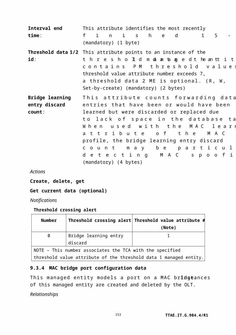
Filter outer VID: (13 bits)
0..4094 Filter received frames on this outer VID value.4096 Do not filter on the outer VID.
Other values: Reserved
Filter outer TPID/DE:
(3 bits)
000 Do not filter on outer TPID field.100 Outer TPID = 8100.101 Outer TPID = input TPID attribute value, do not care about
DE bit.110 Outer TPID = input TPID, DE=0.111 Outer TPID = input TPID, DE=1.
Padding: 12 bits
Filter inner priority:(4 bits)
0..7 Filter received frames on this inner priority value.8 Do not filter on inner priority.14 This is the default filter when no other one-tag rule applies.15 This entry is a no-tag rule; ignore all other VLAN tag filter
fields.
NOTE – The Ethertype filter field is a valid criterion.
Other values: Reserved
Filter inner VID: (13 bits)
0..4094 Filter received frames on this inner VID value.4096 Do not filter on the inner VID.
Other values: Reserved
Filter inner TPID/DE:
(3 bits)
000 Do not filter on inner TPID field.100 Inner TPID = 8100.101 Inner TPID = input TPID attribute value, don't care about DE bit.110 Inner TPID = input TPID, DE=0.111 Inner TPID = input TPID, DE=1.
Padding: 8 bits
Filter Ethertype: (4 bits) The Ethertype value on which to filter received frames, as listed below.
TTAE.IT.G.984.4/R1153

NOTE 2 – This filter is recommended for use on untagged frames or frames with only priority.
0 Do not filter on Ethertype.1 Ethertype = 0x0800 (filter IPoE frames).2 Ethertype = 0x8863 or 0x8864 (filter PPPoE frames).3 Ethertype = 0x0806 (filter ARP frames).
Other values: Reserved
Treatment tags to remove:
(2 bits)
0..2 Remove 0, 1 or 2 tags, respectively. If one tag is specified, then the outer tag is stripped from double-tagged frames.
3 Discard the frame. No symmetric downstream operation exists; i.e., this rule is ignored in the downstream direction.
Padding: (10 bits).
Treatment outer priority:
(4 bits)
0..7 Add an outer tag, and insert this value as the priority in the outer VLAN tag.
8 Add an outer tag, and copy the outer priority from the inner priority of the received frame.
9 Add an outer tag, and copy the outer priority from the outer priority of the received frame.
10 Add an outer tag, and derive P bits from the DSCP field of the incoming frame according to the DSCP to P-bit mapping attribute.
15 Do not add an outer tag.
Other values: Reserved.
TTAE.IT.G.984.4/R1154

Treatment outer VID:
(13 bits)
000..4094 Use this value as the VID in the outer VLAN tag.4096 Copy the outer VID from the inner VID of the received
frame.4097 Copy the outer VID from the outer VID of the received
frame.
Other values: Reserved
Treatment outer TPID/DE:
(3 bits)
000 Copy TPID (and DE, if present) from inner tag of received frame.
001 Copy TPID (and DE, if present) from outer tag of received frame.
010 Set TPID = output TPID attribute value, copy DE bit from inner tag of received frame.
011 Set TPID = output TPID, copy DE from outer tag of received frame.
100 Set TPID = 0x8100.101 Reserved.110 Set TPID = output TPID, DE=0.111 Set TPID = output TPID, DE=1.
Padding: 12 bits
Treatment inner priority:
(4 bits)
0..7 Add an inner tag, and insert this value as the priority to insert in the inner VLAN tag.
8 Add an inner tag, and copy the inner priority from the inner priority of the received frame.
9 Add an inner tag, and copy the inner priority from the outer priority of the received frame.
10 Add an inner tag, and derive P bits from the DSCP field of the incoming frame according to the DSCP to P-bit mapping attribute.
15 Do not add an inner tag.
Other values: Reserved.
TTAE.IT.G.984.4/R1155

Treatment inner VID:
(13 bits)
000..4094 Use this value as the VID in the inner VLAN tag.4096 Copy the inner VID from the inner VID of the received
frame.4097 Copy the inner VID from the outer VID of the received
frame.
Other values: Reserved
Treatment inner TPID/DE:
(3 bits)
000 Copy TPID (and DE, if present) from inner tag of received frame.
001 Copy TPID (and DE, if present) from outer tag of received frame.
010 Set TPID = output TPID attribute value, copy DE bit from inner tag of received frame.
011 Set TPID = output TPID, copy DE from outer tag of received frame.
100 Set TPID = 0x8100.101 Reserved.110 Set TPID = output TPID, DE=0.111 Set TPID = output TPID, DE=1.
Associated ME pointer:
This attribute points to the ME with which this extended VLAN tagging operation configuration data ME is associated.
NOTE 3 – When the association type is xDSL, the two most significant bits may be used to indicate a bearer channel.
(R, W, Set-by-create) (mandatory) (2 bytes)
DSCP to P-bit mapping:
This attribute specifies mapping from DSCP to P-bits. The attribute can be considered a bit string sequence of 64 3-bit groups. The 64 sequence entries represent the possible values of the 6-bit DSCP field. Each 3-bit group specifies the P-bit value to which the associated DSCP value should be mapped. (R, W) (optional) (24 bytes)NOTE 5 – If certain bits in the DSCP field are to be ignored in the mapping process, the attribute should be provisioned such that all possible values of those bits produce the same P-bit mapping. This can be applied to the case where instead of full DSCP, the operator wishes to adopt the priority mechanism based on IP precedence, which needs only the three MSBs of the DSCP field.
Actions
TTAE.IT.G.984.4/R1156

Create, delete, get, get next, set, Set table (optional)
Notifications
None.
Action type
Filter Treatment
Outer Inner
Tag
s to
Rem
ove
Outer Inner
Prio
rity
VID
Prio
rity
VID
Eth
erT
ype
Prio
rity
VID
Prio
rity
VID
Untagged frames
Insert 1 full tag
(X):
F X-F
15 4096 15 4096 0 0 15 N/A Px X
Default case, do
nothing15 4096 15 4096 0 0 15 N/A 15 N/A
Insert 2 tags (X,Y):
F Y-X-F15 4096 15 4096 0 0 Py Y Px X
Single tagged
frames
Insert 1 full tag
(X):
C-F X-C-F
15 4096 8 C 0 0 15 N/A Px X
Insert 1 tag (X),
copy priority:
C-F X-C-F
15 4096 8 C 0 0 15 N/A 8 X
Insert 2 tags (X,Y):
C-F Y-X-C-F15 4096 8 C 0 0 Py Y Px X
Modify tag:
C-F X-F15 4096 8 C 0 1 15 N/A Px X
Modify tag,
keep original
priority:
C-F X-F
15 4096 8 C 0 1 15 N/A 8 X
Modify and insert
tag:
C-F Y-X-F
15 4096 8 C 0 1 Py Y Px X
Remove tag:
C-F F15 4096 8 C 0 1 15 N/A 15 N/A
TTAE.IT.G.984.4/R1157

Action type
Filter Treatment
Outer Inner
Tag
s to
Rem
ove
Outer Inner
Prio
rity
VID
Prio
rity
VID
Eth
erT
ype
Prio
rity
VID
Prio
rity
VID
Default case, do
nothing15 4096 14 4096 0 0 15 N/A 15 N/A
Insert two tags:
C-F Y-X-C-F15 4096 8 C 0 0 Py Y Px X
Double tagged
frames
Insert 1 tag (X):
S-C-F X-S-C-F8 S 8 C 0 0 15 N/A Px X
Insert 1 tag (X),
copy external
priority:
S-C-F X-S-C-F
8 S 8 C 0 0 15 N/A 9 X
Insert 2 tags (X,Y):
S-C-F Y-X-S-
C-F
8 S 8 C 0 0 Py Y Px X
Insert 2 tags (X,Y),
copy external and
internal priority:
S-C-F Y-X-S-
C-F
8 S 8 C 0 0 9 Y 8 X
Modify external
tag:
S-C-F X-C-F
8 S 8 C 0 1 15 N/A Px X
Modify external
tag,
keep original
priority:
S-C-F X-C-F
8 S 8 C 0 1 15 N/A 9 X
Modify both tags:
S-C-F Y-X-F8 S 8 C 0 2 Py Y Px X
TTAE.IT.G.984.4/R1158

Action type
Filter Treatment
Outer Inner
Tag
s to
Rem
ove
Outer Inner
Prio
rity
VID
Prio
rity
VID
Eth
erT
ype
Prio
rity
VID
Prio
rity
VID
Modify both tags,
keep original
priorities:
S-C-F Y-X-F
8 S 8 C 0 2 9 Y 8 X
Swap both tags:
S-C-F C-S-F8 S 8 C 0 2 8 4096 9 4097
Remove outer tag:
S-C-F C-F8 S 8 C 0 1 15 N/A 15 N/A
Remove both tags:
S-C-F F8 S 8 C 0 2 15 N/A 15 N/A
Default case, do
nothing
S-C-F S-C-F
14 4096 14 4096 0 0 15 N/A 15 N/A
9.3.14 Dot1X port extension package
An instance of this managed entity represents a set of attributes that control a port's [b-IEEE 802.1X] operation. It is created and deleted autonomously by the ONT upon creation or deletion of a PPTP that supports 802.1X authentication.
Relationships
An instance of this managed entity is associated with a physical path termination point that performs IEEE 802 authentication (i.e., Ethernet or DSL).
Attributes
TTAE.IT.G.984.4/R1159

Managed entity id:
This attribute provides a unique number for each instance of this managed entity. Its value is the same as that of its associated physical path termination point (i.e., slot and port number).
NOTE – When the associated port is xDSL, the two most significant bits may be used to indicate a bearer channel. (R) (mandatory) (2 bytes)
Dot1x enable: If set true, this Boolean attribute forces the associated port to authenticate via [b-IEEE 802.1X] as a precondition of normal service. The default value false does not impose 802.1X authentication on the associated port. (R, W) (mandatory) (1 byte)
Action register: This attribute defines a set of actions that can be performed on the associated port. The act of writing to the register causes the specified action.
1) Force reauthentication: This opcode initiates an 802.1X reauthentication conversation with the associated port. The port remains in its currently authorized state until the conversation concludes.
2) Force unauthenticated: This opcode initiates an 802.1X authentication conversation whose outcome is predestined to fail, thereby disabling normal Ethernet service on the port. The port's provisioning is not changed, such that upon reinitialization, a new 802.1X conversation may restore service without prejudice.
3) Force authenticated: This opcode initiates an 802.1X authentication conversation whose outcome is predestined to succeed, thereby unconditionally enabling normal Ethernet service on the port. The port's provisioning is not changed, such that upon reinitialization, a new 802.1X conversation is required.
(W) (mandatory) (1 byte)
TTAE.IT.G.984.4/R1160

Authenticator PAE state:
This attribute returns the value of the port's PAE state. States are further described in [b-IEEE 802.1X]. Values are coded as shown below:
0 Initialize.1 Disconnected.2 Connecting.3 Authenticating.4 Authenticated.5 Aborting.6 Held.7 Force auth.8 Force unauth.9 Restart.
(R) (optional) (1 byte)
Backend authentication state:
This attribute returns the value of the port's back-end authentication state. States are further described in [b-IEEE 802.1X]. Values are coded as shown below:
0 Request.1 Response.2 Success.3 Fail.4 Timeout.5 Idle.6 Initialize.7 Ignore.
(R) (optional) (1 byte)
Admin controlled directions:
This attribute controls the directionality of the port's authentication requirement. The default value 0 indicates that control is imposed in both directions. The value 1 indicates that control is imposed only on traffic from the subscriber toward the network. (R, W) (optional) (1 byte)
Operational controlled directions:
This attribute indicates the actual directionality of the port's authentication. The value 0 indicates that control is imposed in both directions. The value 1 indicates that control is imposed only on traffic from the subscriber toward the network. (R) (optional) (1 byte)
Authenticator controlled port status:
This read-only attribute indicates whether the controlled port is currently authorized (1) or unauthorized (2). (R) (optional) (1 byte)
TTAE.IT.G.984.4/R1161

Quiet period: This attribute specifies the interval between EAP request/identity invitations sent to the peer. Other events such as carrier present or EAPOL start frames from the peer may trigger an EAP request/identity frame from the ONT at any time; this attribute controls the ONT's periodic behaviour in the absence of these other inputs. It is expressed in seconds. (R, W) (optional) (2 bytes)
Server timeout period:
This attribute specifies the time the ONT will wait for a response from the radius server before timing out. Within this maximum interval, the ONT may initiate several retransmissions with exponentially increasing delay. Upon timeout, the ONT may try another radius server if there is one, or invoke the fallback policy, if no alternate radius servers are available. Server timeout is expressed in seconds, with a default value of 30 and a maximum value of 65535 seconds. (R, W) (optional) (2 bytes)
Reauthentication period:
This attribute records the reauthentication interval specified by the radius authentication server. It is expressed in seconds. The attribute is only meaningful after a port has been authenticated. (R) (optional) (2 bytes)
Reauthentication enabled:
This Boolean attribute records whether the radius authentication server has enabled reauthentication on this service (true) or not (false). The attribute is only meaningful after a port has been authenticated. (R) (optional) (1 byte)
Key transmission enabled:
This Boolean attribute indicates whether key transmission is enabled (true) or not (false). This feature is not required; the parameter is listed here for completeness vis-à-vis [b-IEEE 802.1X]. (R, W) (optional) (1 byte)
Actions
Get, set
Notifications
Alarm
Number Alarm Description
0 Dot1x local authentication –
allowed
No radius authentication server was accessible. In
accordance with local policy, the port was allowed
access without authentication.
1 Dot1x local authentication –
denied
No radius authentication server was accessible. In
accordance with local policy, the port was denied
access.
2..207 Reserved
208..223 Vendor-specific alarms Not to be standardized
TTAE.IT.G.984.4/R1162

9.3.15 Dot1X configuration profile
An instance of this managed entity represents a set of attributes that control an ONT's [b-IEEE 802.1X] operation with regard to IEEE 802 services. An instance of this managed entity is created by the ONT if it is capable of supporting [b-IEEE 802.1X].
Relationships
One instance of this managed entity governs the ONT's 802.1X behaviour.
Attributes
TTAE.IT.G.984.4/R1163

Managed entity id: This attribute provides a unique number for each instance of this managed entity. There is at most one instance, number 0. (R) (mandatory) (2 bytes)
Circuit ID prefix: This attribute is a pointer to a large string managed entity whose content appears as the prefix of the NAS port ID in radius access-request messages. The remainder of the NAS port ID field is local information (for example slot-port, appended by the ONT itself). The default value of this attribute is the null pointer 0. (R, W) (mandatory) (2 bytes)
Fallback policy: When set to 1 (deny), this attribute causes 802.1X conversations to fail when no external authentication server is accessible, such that no Ethernet service is provided. The default value 0 causes 802.1X conversations to succeed when no external authentication server is accessible. (R, W) (mandatory) (1 byte)
Auth server 1: This attribute is a pointer to a large string managed entity that contains the URI of the first choice radius authentication server. The value 0 indicates that no radius authentication server is specified. (R, W) (mandatory) (2 bytes)
Shared secret auth1:
This attribute is the shared secret for the first radius authentication server. It is a null-terminated character string. (R, W) (mandatory) (25 bytes)
The following two pairs of attributes are defined in the same way:
Auth server 2: (R, W) (optional) (2 bytes)
Shared secret auth2:
(R, W) (optional) (25 bytes)
Auth server 3: (R, W) (optional) (2 bytes)
Shared secret auth3:
(R, W) (optional) (25 bytes)
OLT proxy address:
This attribute indicates the IP address of a possible proxy at the OLT for 802.1X radius messages. The default value 0.0.0.0 indicates that no proxy is required. (R, W) (optional) (4 bytes)
Actions
Get, set
Notifications
None.
TTAE.IT.G.984.4/R1164

9.3.16 Dot1X performance monitoring history data
This managed entity collects performance statistics on an ONT's IEEE 802.1X operation. Instances of this managed entity are created and deleted by the ONT on request of the OLT.
Relationships
An instance of this managed entity may be associated with each UNI that can perform IEEE 802 authentication.
Attributes
TTAE.IT.G.984.4/R1165

Managed entity id: This attribute uniquely identifies each instance of this managed entity. Through an identical ID, this managed entity is implicitly linked to an instance of a physical path termination point.(R, Set-by-create) (mandatory) (2 bytes)
Interval end time: This attribute identifies the most recently finished 15-minute interval. (R) (mandatory) (1 byte)
Threshold data 1/2 id: This attribute points to an instance of the threshold data 1 and 2 managed entities that contains PM threshold values. (R, W, Set-by-create) (mandatory) (2 bytes)
EAPOL frames received:
This attribute counts received valid EAPOL frames of any type. (R) (mandatory) (4 bytes)
EAPOL frames transmitted:
This attribute counts transmitted EAPOL frames of any type. (R) (mandatory) (4 bytes)
EAPOL start frames received:
This attribute counts received EAPOL start frames. (R) (mandatory) (4 bytes)
EAPOL logoff framesreceived:
This attribute counts received EAPOL logoff frames. (R) (mandatory) (4 bytes)
Invalid EAPOL frames received:
This attribute counts received EAPOL frames in which the frame type was not recognized. (R) (mandatory) (4 bytes)
EAP resp/id frames received:
This attribute counts received EAP response frames containing an identifier type field. (R) (mandatory) (4 bytes)
EAP response framesreceived:
This attribute counts received EAP response frames, other than resp/id frames. (R) (mandatory) (4 bytes)
EAP initial request frames transmitted:
This attribute counts transmitted request frames containing an identifier type field. In [b-IEEE 802.1X], this is also called ReqId. (R) (mandatory) (4 bytes)
EAP request frames transmitted:
This attribute counts transmitted request frames, other than request/id frames. (R) (mandatory) (4 bytes)
EAP length error frames received:
This attribute counts received EAPOL frames whose packet body length field was invalid. (R) (mandatory) (4 bytes)
EAP success frames generated autonomously:
This attribute counts EAPOL success frames generated according to local fallback policy because no radius server was available. (R) (mandatory) (4 bytes)
EAP failure frames generated
This attribute counts EAPOL failure frames generated according to local fallback policy because no radius server was available. (R)
TTAE.IT.G.984.4/R1166

autonomously: (mandatory) (4 bytes)
Actions
Create, delete, get, set
Get current data (optional)
Notifications
Threshold crossing alert
Number Threshold crossing alert Threshold value attribute # (Note)
0..3 Reserved
4 Invalid EAPOL frames received 5
5..8 Reserved
9 EAP length error frames
received
10
NOTE – This number associates the TCA with the specified threshold value attribute of the
threshold data 1 managed entity.
9.3.17 Radius performance monitoring history data
This managed entity collects performance statistics on an ONT's radius client, particularly as related to its 802.1X operation.
Instances of this managed entity are created and deleted by the OLT.
For a complete discussion of generic PM architecture, refer to clause I.1.9.
Relationships
An instance of this managed entity is associated with an ONT.
Attributes
TTAE.IT.G.984.4/R1167

Managed entity id: This attribute uniquely identifies each instance of this managed entity. Through an identical ID (namely 0), this managed entity is implicitly linked to an instance of a dot1X configuration profile.(R, Set-by-create) (mandatory) (2 bytes)
Interval end time: This attribute identifies the most recently finished 15-minute interval. (R) (mandatory) (1 byte)
Threshold data 1/2 id:
This attribute points to an instance of the threshold data 1 managed entity that contains PM threshold values. Since no threshold value attribute number exceeds 7, a threshold data 2 ME is optional. (R, W, Set-by-create) (mandatory) (2 bytes)
Access-request packets transmitted:
This attribute counts transmitted radius access-request messages, including retransmissions. (R) (mandatory) (4 bytes)
Access-request retransmission count:
This attribute counts radius access-request retransmissions. (R) (mandatory) (4 bytes)
Access-challenge packets received:
This attribute counts received radius access-challenge messages. (R) (mandatory) (4 bytes)
Access-accept packets received:
This attribute counts received radius access-accept messages. (R) (mandatory) (4 bytes)
Access-reject packets received:
This attribute counts received radius access-reject messages. (R) (mandatory) (4 bytes)
Invalid radius packets received:
This attribute counts received invalid radius messages. (R) (mandatory) (4 bytes)
Actions
Create, delete, get, set
Get current data (optional)
Notifications
Threshold crossing alert
Number Threshold crossing alert Threshold value attribute # (Note)
0 Reserved
1 Retransmission count 2
2..4 Reserved
5 Invalid radius packets received 6
TTAE.IT.G.984.4/R1168

NOTE – This number associates the TCA with the specified threshold value attribute of the
threshold data 1 managed entity.
9.3.18 Dot1 rate limiter
This managed entity allows rate limits to be defined for various types of upstream traffic that are processed by 802.1 bridges or related structures.
Relationships
An instance of this managed entity may be linked to an instance of the MAC bridge service profile, an 802.1p mapper or other managed entities.
Attributes
Managed entity id: This attribute uniquely identifies each instance of this managed entity. (R, Set-by-create) (mandatory) (2 bytes)
Parent ME pointer: This attribute points to an instance of a managed entity. The type of managed entity is determined by the TP type attribute. (R, W, Set-by-create) (mandatory) (2 bytes)
TP type: This attribute identifies the type of termination point associated with this dot1 rate limiter. Valid values are:
1 MAC bridge configuration data.2 802.1p mapper service profile.
(R, W, Set-by-create) (mandatory) (1 byte)
Upstream unicast flood rate pointer:
This attribute points to an instance of the traffic descriptor that specifies the maximum rate of upstream unicast packets whose destination address is unknown to the bridge. A null pointer specifies that no administrative limit is to be imposed. (R, W, Set-by-create) (optional) (2 bytes)
Upstream broadcast rate pointer:
This attribute points to an instance of the traffic descriptor that specifies the maximum rate of upstream broadcast packets. A null pointer specifies that no administrative limit is to be imposed. (R, W, Set-by-create) (optional) (2 bytes)
Upstream multicast payload rate pointer:
This attribute points to an instance of the traffic descriptor that specifies the maximum rate of upstream multicast payload packets. A null pointer specifies that no administrative limit is to be imposed. (R, W, Set-by-create) (optional) (2 bytes)
Actions
Create, delete, get, set, Set table (optional)
TTAE.IT.G.984.4/R1169

Notifications
None.
9.3.19 Dot1ag maintenance domain
A maintenance domain (MD) is a context within which CFM connectivity verification can occur. Individual services (maintenance associations: MAs) exist within an MD. A maintenance domain is created and deleted by the OLT. The MD managed entity is specified by [b-IEEE 802.1ag] in such a way that the same provisioning can be used for all associated systems in a network; the OMCI definition accordingly avoids ONT-specific information such as pointers.
Relationships
Several MDs may be associated with a given bridge, at various MD levels, and a given MD may be associated with any number of bridges.
Attributes
Managed entity id: This attribute uniquely identifies an instance of this managed entity. The values 0 and 0xFFFF are reserved. (R, Set-by-create) (mandatory) (2 bytes)
MD level: This attribute ranges from 0..7 and specifies the maintenance level of this MD. Higher numbers have wider geographic scope. (R, W, Set-by-create) (mandatory) (1 byte)
MD name format: This attribute specifies one of several possible formats for the MD name attribute. (R, W, Set-by-create) (mandatory) (1 byte)
Value MD name format MD name attribute Defined in
1 None No MD name present [b-IEEE 802.1ag]
2 DNS-like name Globally unique text string derived from a
DNS name
"
3 MAC addr and
UINT
MAC address, followed by a two-octet
unsigned integer, total length 8 bytes
"
4 Character string String of printable characters. This is
recommended to be the default value.
"
32 ICC-based ITU carrier code followed by locally
assigned UMC code, 13 bytes with trailing
nulls as needed
[b-ITU-T Y.1731]
(Annex A)
Others Reserved
TTAE.IT.G.984.4/R1170

MD name 1, MD name 2: These two attributes may be regarded as a 50-byte octet string whose value is the left-justified maintenance domain name. The MD name may or may not be a printable character string, so an octet string is the appropriate representation. If the MD name format specifies a DNS-like name or a character string, the string is null-terminated; otherwise its length is determined by the MD name format. If the MD has no name (MD name format = 0), this attribute is undefined. Note that binary comparisons of the MD name are made in other CFM state machines, so blanks, alphabetic case, etc., are significant. Further note that the maintenance domain name and the maintenance association name must be packed (with additional bytes) into 48-byte CFM message headers. (R, W) (mandatory if MD name format is not 1) (25 bytes * 2 attributes)
MHF creation: This attribute determines whether an associated bridge creates an MHF for this MD or not, under circumstances defined in clause 22.2.3 of [b-IEEE 802.1ag]. This attribute is an enumeration with the following values:
1 None, the default value.
2 Default. The bridge can create MHFs on an associated VID on any port through which the VID can pass, where: i) there are no lower active MD levels or ii) there is a MEP at the next lower active MD level on the port.
3 Explicit. The bridge can create MHFs on an associated VID on any port through which the VID can pass, but only if a MEP exists at some lower maintenance level.
(R, W, Set-by-create) (mandatory) (1 byte)
Sender ID permission: This attribute determines the content of the sender ID TLV included in CFM messages transmitted by maintenance points controlled by this MD. Chassis ID and management address information is available from the dot1ag chassis-management info managed entity. The attribute is an enumeration with the following values:
1 None: The sender ID TLV is not to be sent, default.2 Chassis: The chassis ID length, chassis ID subtype, and
chassis ID fields of the sender ID TLV are to be sent, but not the management address fields.
TTAE.IT.G.984.4/R1171
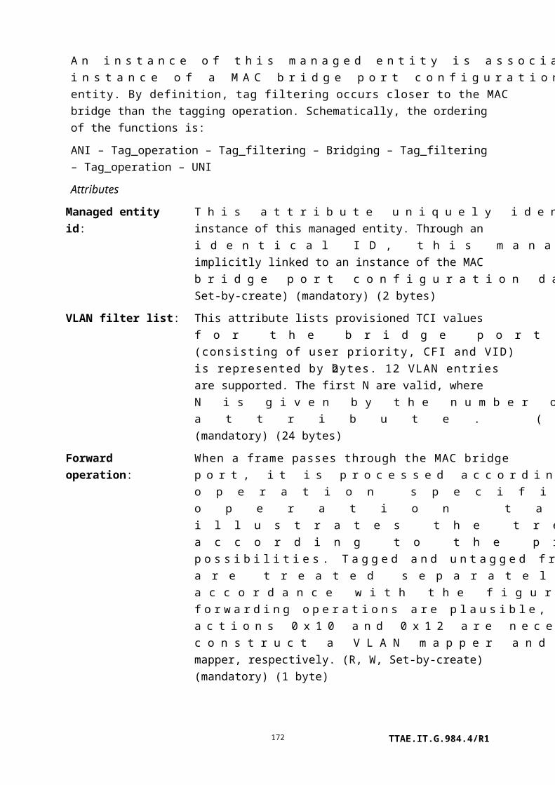
3 Manage: The management address fields of the sender ID TLV are to be sent, but the chassis ID length is to be transmitted with a 0 value, and the chassis ID subtype, and chassis ID fields are not to be sent.
4 ChassisManage: All chassis ID and management address fields are to be sent.
(R, W, Set-by-create) (mandatory) (1 byte)
Actions
Create, delete, get, set
Notifications
None.
9.3.20 Dot1ag maintenance association
This managed entity models an IEEE 802.1 service defined on a bridge port. A maintenance association (MA) is a set of endpoints on opposite sides of a network, all existing at a defined maintenance level. One of the endpoints resides on the local ONT; the others are understood to be configured in a consistent way on external equipments. [b-ITU-T Y.1731] refers to the MA as a maintenance entity group (MEG).
A maintenance association is created and deleted by the OLT.
Relationships
Any number of MAs may be associated with a given maintenance domain, or may stand on their own without an MD. One or more MAs may be associated with a MAC bridge or 802.1p mapper. An MA exists at one of eight possible maintenance levels.
Attributes
TTAE.IT.G.984.4/R1172

Managed entity id: This attribute uniquely identifies an instance of this managed entity. The values 0 and 0xffff are reserved. (R, Set-by-create) (mandatory) (2 bytes)
MD pointer: This pointer specifies the dot1ag maintenance domain with which this MA is associated. The default null pointer specifies that the MA is not associated with an MD. (R, W, Set-by-create) (mandatory) (2 bytes)
Short MA name format: This attribute specifies one of several possible formats for the short MA name attribute. Value 1, the primary VLAN ID, is recommended to be the default. (R, W, Set-by-create) (mandatory) (1 byte)
Value Short MA name format Short MA name attribute
1 Primary VID 2 octets, 12 LSBs specify primary VID, 0 if none
2 Character string String of up to 45 printable characters
3 Two-byte integer 2-octet unsigned integer
4 VPN ID 7 octets, as defined in [b-IETF RFC 2685]
Other Reserved
Short MA name 1, Short MA name 2:
These two attributes may be regarded as an octet string whose value is the left-justified maintenance association name. Because the MA name may or may not be a printable character string, an octet string is the appropriate representation. If the short MA name format specifies a character string, the string is null-terminated; otherwise its length is determined by the short MA name format. Note that binary comparisons of the short MA name are made in other CFM state machines, so blanks, alphabetic case, etc., are significant. Further note that the maintenance domain name and the maintenance association short name must be packed (with additional bytes) into 48-byte CFM message headers. (R, W) (mandatory) (25 bytes * 2 attributes)
TTAE.IT.G.984.4/R1173

CCM interval: If CCMs are enabled on a MEP, the CCM interval attribute specifies the rate at which they are generated. The MEP also expects to receive CCMs from each of the other MEPs in its CC database at this rate.
0: CCM transmission disabled.1: 3.33 ms.2: 10 ms.3: 100 ms.4: 1 s.5: 10 s.6: 1 min.7: 10 min.
Short intervals should be used judiciously, as they can interfere with the network's ability to handle subscriber traffic. The recommended value is 1 second. (R, W, Set-by-create) (mandatory) (1 byte)
Associated VLANs: This attribute is a list of up to 12 VLAN IDs with which this MA is associated. Once a set of VLANs is defined, the ONT should deny operations to other dot1ag maintenance associations or dot1ag default MD level entries that conflict with the set membership. The all-zeros value indicates that this MA is not associated with any VLANs. Assuming that the attribute is not 0, the first entry is understood to be the primary VLAN. Except forwarded LTMs, CFM messages emitted by maintenance points in this MA are tagged with the primary VLAN ID. (R, W) (mandatory) (2 bytes/entry * 12 entries = 24 bytes)
MHF creation: This attribute determines whether the bridge creates an MHF or not, under circumstances defined in clause 22.2.3 of [b-IEEE 802.1ag]. This attribute is an enumeration with the following values:
1 None; no MHFs are created on this bridge for this MA.
2 Default. The bridge can create MHFs on this VID on any port through which the VID can pass.
3 Explicit. The bridge can create MHFs on this VID on any port through which the VID can pass, but only if a MEP exists at some lower maintenance level.
TTAE.IT.G.984.4/R1174

4 Defer. This value causes the ONT to use the setting of the parent MD. This is recommended to be the default value.
(R, W, Set-by-create) (mandatory) (1 byte)
Sender ID permission: This attribute determines the content of the sender ID TLV included in CFM messages transmitted by maintenance points controlled by this MA. This attribute is the same as that defined in the description of the dot1ag maintenance domain managed entity, with the addition of code point 5.
1 None: The sender ID TLV is not to be sent, default.
2 Chassis: The chassis ID length, chassis ID subtype, and chassis ID fields of the sender ID TLV are to be sent, but not the management address fields.
3 Manage: The management address fields of the sender ID TLV are to be sent, but the chassis ID length is to be transmitted with a 0 value, and the chassis ID subtype, and chassis ID fields are not to be sent.
4 ChassisManage: All chassis ID and management address fields are to be sent.
5 Defer: The content of the sender ID TLV is determined by the corresponding maintenance domain attribute. This is recommended to be the default value.
(R, W, Set-by-create) (mandatory) (1 byte)
Actions
Create, delete, get, set
Notifications
None.
9.3.21 Dot1ag default MD level
An MHF is a collection of functionality that is not explicitly modelled as a managed entity by either [b-IEEE 802.1ag] or OMCI. The ONT automatically creates MHFs according to parameters specified in a dot1ag maintenance domain or a dot1ag maintenance association ME; the dot1ag default MD level ME catches the corner cases not covered by other MEs, specifically VLANs not included by any defined MA.
The dot1ag default MD level comprises a configurable table, each entry of which specifies default MHF functionality for some set of VLANs. Once a set of VLANs is defined,
TTAE.IT.G.984.4/R1175

operations to different table entries or to dot1ag maintenance associations that conflict with the set membership should be denied. In addition, catch-all attributes are defined to specify MHF functionality when there is no match to either a table entry or an MA.
Relationships
An ONT that supports [b-IEEE 802.1ag] automatically creates one instance of this ME for each MAC bridge or 802.1p mapper, depending on the ONT's provisioning model. It should not create an instance for an 802.1p mapper that is associated with a MAC bridge.
Attributes
Managed entity id: This attribute uniquely identifies an instance of this managed entity. Through an identical ID, this managed entity is implicitly linked to an instance of the MAC bridge service profile ME or an 802.1p mapper ME. It is expected that an ONT will implement CFM on bridges or on 802.1p mappers, but not both, depending on its provisioning model. For precision, the reference is disambiguated by the value of the layer 2 type pointer attribute. (R) (mandatory) (2 bytes)
Layer 2 type: This attribute specifies whether the dot1ag default MD level ME is associated with a MAC bridge service profile (value 0) or an 802.1p mapper (value 1). (R) (mandatory) (1 byte)
Catchall level: This attribute ranges from 0..7 and specifies the MD level of MHFs created when no more specific match is found. (R, W) (mandatory) (1 byte)
TTAE.IT.G.984.4/R1176

Catchall MHF creation: This attribute determines whether, when no more specific match is found, the bridge creates an MHF or not. This attribute is an enumeration with the following values:
1 None; the bridge creates no MHFs. This is the default value.
2 Default. The bridge can create MHFs on this VID on any port through which the VID can pass.
3 Explicit. The bridge can create MHFs on this VID on any port through which the VID can pass, but only if a MEP exists at some lower maintenance level.
(R, W) (mandatory) (1 byte)
Catchall sender ID permission:
This attribute determines the content of the sender ID TLV included in CFM messages transmitted by maintenance points when no more specific match is found. This attribute is identical to that defined in the description of the dot1ag maintenance domain managed entity (i.e., excluding codepoint 5, defer). (R, W) (mandatory) (1 byte)
Default MD level table: Each entry is a vector of fields, indexed by primary VLAN ID.
Primary VLAN ID (2 bytes)
Table control: This field controls the meaning of a set operation. The one-byte size of this field is included in get/get-next operations, but its value is undefined under get-next. (1 byte)
1 Add record to table; overwrite existing record, if any.2 Delete record from table.3 Clear all entries from table. This action may affect service
and should be used judiciously.
Other values reserved.
Status: This Boolean field indicates whether this table entry is in effect (true) or whether (false) it has been overridden by the existence of an MA for the same VID and MD level as this table's entry, and on which an up MEP is defined. This attribute is read-only. Space should be allocated for it during set operations, but the value is not used. (1 byte)
Level: This field ranges from 0..7 and specifies the MD level of MHFs under the control of this instance of the dot1ag default MD level. The additional value 0xFF instructs the bridge to use the
TTAE.IT.G.984.4/R1177

value in the catchall level attribute. (1 byte)
MHF creation: This attribute determines whether the bridge creates an MHF or not, under circumstances defined in clause 22.2.3 of [b-IEEE 802.1ag]. This attribute is an enumeration with the following values (1 byte):
1 None; no MHFs are created on this bridge for this MA.
2 Default. The bridge can create MHFs on this VID on any port through which the VID can pass.
3 Explicit. The bridge can create MHFs on this VID on any port through which the VID can pass, but only if a MEP exists at some lower maintenance level.
4 Defer. This value causes the ONT to use the setting of the catchall MHF creation attribute. This is recommended to be the default value.
Sender ID permission: This attribute determines the content of the sender ID TLV included in CFM messages transmitted by maintenance points controlled by this MA. (1 byte)
1 None: The sender ID TLV is not to be sent, default.
2 Chassis: The chassis ID length, chassis ID subtype, and chassis ID fields of the sender ID TLV are to be sent, but not the management address fields.
3 Manage: The management address fields of the sender ID TLV are to be sent, but the chassis ID length is to be transmitted with a 0 value, and the chassis ID subtype, and chassis ID fields are not to be sent.
4 ChassisManage: All chassis ID and management address fields are to be sent.
5 Defer: The content of the sender ID TLV is determined by the catchall sender ID permission attribute.
Associated VLANs list: This field comprises a list of up to 11 additional VLAN IDs associated with the primary VLAN, 2 bytes each. Unused placeholders, possibly including the entire field, are set to 0. (22 bytes)
(R, W) (mandatory) (29 bytes * N entries)
Actions
TTAE.IT.G.984.4/R1178

Get, get next, set
Notifications
None.
9.3.22 Dot1ag MEP
This managed entity models a maintenance association end point (MEP) as defined primarily in [b-IEEE 802.1ag] and secondarily in [b-ITU-T Y.1731]. It is created and deleted by the OLT. A MEP exists at one of eight possible maintenance levels, and resides at the boundary of a maintenance domain. It inherits a name, and optionally a set of associated VLANs, from its associated MA.
Relationships
One or more MEPs may be associated with a MAC bridge port or an 802.1p mapper in the absence of a MAC bridge. A MEP is also associated with zero or more VLANs and a maintenance association.
Attributes
Managed entity id: This attribute uniquely identifies each instance of this managed entity. (R, Set-by-create) (mandatory) (2 bytes)
Layer 2 entity pointer: Depending on the value of the layer 2 type attribute, this pointer specifies the MAC bridge port configuration data ME or the 802.1p mapper service profile ME with which this MEP is associated. (R, W, Set-by-create) (mandatory) (2 bytes)
Layer 2 type: This attribute specifies whether the MA is associated with a MAC bridge port (value 0) or an 802.1p mapper (value 1). (R, W, Set-by-create) (mandatory) (1 byte)
MA pointer: This pointer specifies the maintenance association (MA) with which this MEP is associated. (R, W, Set-by-create) (mandatory) (2 bytes)
MEP ID: This attribute specifies the MEP's own identity in the MA. For a given MA, the MEP ID must be unique throughout the network defined by the MD. The MEP ID is defined in the range 1..8191. The default value 0 indicates that no MEP ID is (yet) configured. (R, W, Set-by-create) (mandatory) (2 bytes)
MEP control: This attribute specifies some of the overall behavioural aspects of the MEP. It is interpreted as follows. Ethernet AIS generation should not be enabled simultaneously with CCMs.
TTAE.IT.G.984.4/R1179

Bit Interpretation when bit value = 1
1 (LSB) Reserved
2 MEP generates continuity check messages, CCMs
3 Enable Y.1731 server MEP function
4 Enable generation of Ethernet AIS
5 This is an up MEP, facing toward the core of the bridge. If more than
one MEP exists on a given maintenance association and on a given
bridge, all such MEPs must face the same direction.
6..8 Reserved
(R, W, Set-by-create) (mandatory) (1 byte)
Primary VLAN: This attribute is a 12-bit VLAN ID. The value 0 indicates that the MEP inherits its primary VLAN from its parent MA. CFM messages, except forwarded LTMs, are tagged with the primary VLAN ID. If explicitly specified, the value of this attribute must be one of the VLANs associated with the parent MA. (R, W, Set-by-create) (mandatory) (2 bytes)
Administrative state: This attribute locks (1) and unlocks (0) the functions performed by this managed entity. When the administrative state is set to lock, all functions are blocked, and alarms for this managed entity are no longer generated. Because spurious alarms may be generated during the process of configuring CFM across a network, the default value for this attribute is locked. (R, W, Set-by-create) (mandatory) (1 byte)
CCM and LTM priority:
Ranging from 0..7, this attribute permits CCM and LTM frames to be explicitly prioritized, which may be needed if flows are separated, e.g., by 802.1p priority. The priority specified in this attribute is also used in LTR frames originated by this MEP. The value 0xFF selects the 802.1ag default, whereby CCM and LTM frames are transmitted with the highest Ethernet priority available. (R, W, Set-by-create) (mandatory) (1 byte)
TTAE.IT.G.984.4/R1180

Egress identifier: This attribute comprises 8 bytes to be included in LTMs. They allow received LTRs to be directed to the correct originator. The attribute includes the originator MAC address and a locally-defined identifier. If this field is 0 (default), the ONT uses the MEP's MAC address, with 0 as the locally-defined identifier. (R, W, Set-by-create) (mandatory) (8 bytes)
Peer MEP IDs: This attribute lists the expected peer MEPs for CCMs, 2 bytes per MEP ID. [b-IEEE 802.1ag] allows for multipoint networks, and therefore a list of peer MEPs. This attribute allows for up to 12 peers for a given MEP, though G-PON applications are expected to need only a single peer. Missing or unexpected messages trigger alarm declaration after a soak interval. Unused peer MEP slots should be set to 0. (R, W) (mandatory) (24 bytes)
ETH AIS control: This attribute controls the generation of Ethernet AIS frames when they are enabled through the MEP control attribute. It is interpreted as follows:
Bit Interpretation
1 (LSB) Transmission period
0: Once per second
1: Once per minute
2..4 P-bit priority of transmitted ETH AIS frames
5..7 The maintenance level at which the client MEP exists
8 Reserved
(R, W, Set-by-create) (mandatory if ETH AIS is enabled) (1 byte)
Fault alarm threshold: This attribute specifies the lowest priority alarm that is allowed to generate a fault alarm. It is defined as follows:
1 All defects generate alarms after suitable soaking, including AIS and RDICCM.
2 Alarm generated only by one of: MACstatus, RemoteCCM, ErrorCCM, XconCCM. This value is recommended as the default in [b-IEEE 802.1ag].
3 Alarm generated only by one of: RemoteCCM, ErrorCCM,
TTAE.IT.G.984.4/R1181
XconCCM.
4 Alarm generated only by one of: ErrorCCM, XconCCM.
5 Alarm generated only by: XconCCM.
6 No alarms are to be reported. This setting may be useful during configuration of services across the network when spurious alarms could otherwise be generated.
(R, W, Set-by-create) (optional) (1 byte)
Alarm declaration soak time:
This attribute defines the defect soak time that must elapse before the MEP declares an alarm. It is expressed in ten-millisecond units with a range of 250 to 1000, i.e., 2.5 to 10 seconds. The default is recommended to be 2.5 seconds. (R, W) (mandatory) (2 bytes)
Alarm clear soak time: This attribute defines the defect-free soak time that must elapse before the MEP clears an alarm. It is expressed in ten-millisecond units with a range of 250 to 1000, i.e., 2.5 to 10 seconds. The default is recommended to be 10 seconds. (R, W) (mandatory) (2 bytes)
Actions
Create, delete, get, set
Test: The test operation causes the MEP to originate one or more loopback messages (LBMs) or a linktrace message (LTM) in accordance with the message format defined in clauses II.2.27 and II.2.45 (baseline format) and clauses II.3.27 and II.3.45 (extended format).
The link trace test returns its results in a general purpose buffer ME, which must have been created in advance by the OLT. (The general purpose buffer is designated by a pointer in the test message itself.) Upon completion of the linktrace operation, the general purpose buffer contains a sequence of LTR entries in the order they were received:
The link trace test returns its results in a general purpose buffer ME, which must have been created in advance by the OLT. Upon completion of the linktrace operation, the general purpose buffer contains a sequence of LTR entries in the order they were received:
Length field, 2 bytes Length bytes
TTAE.IT.G.984.4/R1182

Length of LTR1 LTR: link trace reply 1 (clause 21.9 of [b-IEEE 802.1ag])
Length of LTR2 LTR: link trace reply 2
Etc.
[b-IEEE 802.1ag] defines the data structure for the linktrace database in detail, but the definition is essentially the same as the LTR PDU itself. OMCI simply records the messages for parsing and analysis at the OLT or the EMS.
If the ONT cannot allocate enough memory for the entire list, it keeps the most recent responses and discards the older LTRs as necessary (LTR1, LTR2, …).
Notifications
Alarm
Number Alarm Description
0 RDI CCM RDI received in CCM from peer MEP
1 MAC status Port or interface status failure at peer MEP
2 Remote CCM Loss of continuity with peer MEP
3 Error CCM Invalid CCMs received
4 Xcon CCM CCMs received from other MA or lower MD level
5 Unexpected period Unexpected period
6 AIS Ethernet AIS received
7..207 Reserved
208..223 Vendor-specific alarms Not to be standardized
9.3.23 Dot1ag MEP status
This managed entity is the read-only twin of the dot1ag MEP. Its purpose is to return information that may help in system- or network-level troubleshooting. It is automatically created and deleted by the ONT at the time its MEP is created or deleted.
As the reporter of ephemeral information, the dot1ag MEP status ME is not persistent and is not included in MIB uploads.
Relationships
A dot1ag MEP status ME is associated with a dot1ag MEP ME.
Attributes
Managed entity id: This attribute uniquely identifies each instance of this managed entity. Through an identical ID, this managed entity is implicitly linked to an instance of the dot1ag MEP ME. (R) (mandatory) (2 bytes)
MEP MAC address: This attribute records the MEP's MAC address. (R) (mandatory)
TTAE.IT.G.984.4/R1183

(6 bytes)
Fault notification generator state:
This attribute records the current state of the MEP's fault notification generator state machine. States are defined in clause 20.35 of [b-IEEE 802.1ag].
1 Reset2 Defect3 Report defect4 Defect reported5 Defect clearing
(R) (mandatory) (1 byte)
Highest priority defect observed:
This attribute records the highest priority defect observed since the fault notification state machine was last in reset state. In increasing priority order, possible values are:
0 No defect observed.1 Received a CCM from a remote MEP in which the RDI bit
was set.2 Received a CCM from a remote MEP in which the port
status or interface status TLV reported an error.3 No CCMs received for at least 3.5 * CCM interval from at
least one remote MEP in the MA.4 Received invalid CCMs for at least 3.5 * CCM interval.5 Received CCMs for at least 3.5 * CCM interval that could
be from some other MA.
(R) (mandatory) (1 byte)
Current defects: This attribute is a bit field that signals several events of interest in real time.
TTAE.IT.G.984.4/R1184

Bit Meaning when set
1 (LSB) Some other MEP in the same MA is currently transmitting RDI.
2 A port status or interface status TLV received from some other MEP in the MA is currently indicating an error condition.
3 CCMs have not been received for at least 3.5 * CCM interval from at least one of the expected remote MEPs.
4 Erroneous CCMs have been received for at least 3.5 * CCM interval from at least one of the remote MEPs in this MA.
5 CCMs have been received for at least 3.5 * CCM interval from a MEP that is not configured into the current MA.
6..8 Reserved
(R) (mandatory) (1 byte)
Last received errored CCM:
This attribute contains the most recently received CCM that contributed to a defErrorCCM fault. If no such CCM has been received, this attribute is null. The format of the CCM is defined in clause 21.6 of [b-IEEE 802.1ag]. (R) (mandatory) (N bytes, not to exceed 128)
Last received xcon CCM: This attribute contains the most recently received CCM that contributed to a defXconCCM fault. If no such CCM has been received, this attribute is null. (R) (mandatory) (N bytes, not to exceed 128)
Out of sequence CCMs count:
This attribute records the number of out of sequence CCMs received. When the counter is full, it rolls over to 0. (R) (optional) (4 bytes)
CCMs transmitted count: This attribute records the number of CCMs transmitted. It may be used as the sequence number of transmitted CCMs. When the counter is full, it rolls over to 0. (R) (mandatory) (4 bytes)
Unexpected LTRs count: This attribute records the number of unexpected LTRs received. When the counter is full, it rolls over to 0. (R) (mandatory) (4 bytes)
LBRs transmitted count: This attribute records the number of LBRs transmitted. When the counter is full, it rolls over to 0. (R) (mandatory) (4 bytes)
TTAE.IT.G.984.4/R1185

Next loopback transaction identifier:
This attribute is the value of the transaction number sent in the next LBM to be transmitted. It is not required to persist over ONT initialization, but it should be initialized to a random value. It increments with each LBM sent, and rolls over when full. (R) (mandatory) (4 bytes)
Next link trace transaction identifier:
This attribute is the value of the transaction number sent in the next LTM to be transmitted. It is not required to persist over ONT initialization. It increments with each LTM sent, and rolls over when full. (R) (mandatory) (4 bytes)
Actions
Get, get next
Notifications
None. This managed entity does not generate AVCs because its attributes change frequently in real time, but are generally only of interest after the corresponding MEP declares an alarm.
9.3.24 Dot1ag MEP CCM database
This managed entity records the recent history of remote MEPs, as deduced by the local parent MEP. Because records are of variable length, and are constantly updated, a separate attribute is defined for each remote MEP. The dot1ag MEP CCM database is automatically created or deleted by the ONT at the time a MEP is created or deleted.
As the reporter of ephemeral information, the dot1ag MEP CCM database ME is not persistent and is not included in MIB uploads.
Relationships
A dot1ag MEP CCM database ME is associated with a dot1ag MEP ME.
Attributes
Managed entity id: This attribute uniquely identifies each instance of this managed entity. Through an identical ID, this managed entity is implicitly linked to an instance of the dot1ag MEP ME. (R) (mandatory) (2 bytes)
Each of the following RMEP database table attributes records information for one of the possible remote MEPs. It is expected that there will be only one remote MEP per MA in G-PON applications, but the ME is defined in a way that permits several RMEPs. The optional attributes are instantiated by the ONT when additional remote MEPs are provisioned on the local MEP. Remote MEP records appear in no particular order, and the order is not
TTAE.IT.G.984.4/R1186

guaranteed to persist across ONT initializations.
RMEP 1 database table:
(R) (mandatory) (N bytes)
RMEP 2 database table:
(R) (optional) (N bytes)
RMEP 3 database table:
(R) (optional) (N bytes)
RMEP 4 database table:
(R) (optional) (N bytes)
RMEP 5 database table:
(R) (optional) (N bytes)
RMEP 6 database table:
(R) (optional) (N bytes)
RMEP 7 database table:
(R) (optional) (N bytes)
RMEP 8 database table:
(R) (optional) (N bytes)
RMEP 9 database table:
(R) (optional) (N bytes)
RMEP 10 database table:
(R) (optional) (N bytes)
RMEP 11 database table:
(R) (optional) (N bytes)
RMEP 12 database table:
(R) (optional) (N bytes)
Each attribute is a record that comprises the following fields:
RMep identifier. The MEP ID of the remote MEP. (2 bytes)
TTAE.IT.G.984.4/R1187
RMep state. An enumeration with the following meaning (1 byte):
1 Idle. Momentary state during reset.2 Start. The timer has not expired since the state machine
was reset, but no valid CCM has yet been received.3 Failed. The timer has expired since the state machine
was reset and since a valid CCM was received.4 Ok. The timer has not expired since a valid CCM was
received.
Failed-ok time. A timestamp, the value of the local ONT's SysUpTime at which the remote MEP state last entered either the failed or ok state. SysUpTime is a count of 10-ms intervals since ONT initialization. The value 0 if it has not been in either of these states since ONT initialization. (4 bytes)
MAC address. The MAC address of the remote RMEP. If no CCM has been received from the remote MEP, this field has the value 0. (6 bytes)
RDI. Boolean indicating whether the RDI bit in the most recently received CCM was set. (1 byte)
Port status. The port status from the most recently received CCM, as defined in clause 21.5.4 of [b-IEEE 802.1ag]. The absence of a received port status TLV is indicated by the value 0. (1 byte)
Interface status. The interface status from the most recently received CCM, as defined in clause 21.5.5 of [b-IEEE 802.1ag]. The absence of a received interface status TLV is indicated by the value 0. (1 byte)
Sender ID TLV. This is the actual sender ID TLV from the most recently received CCM, as defined in clause 21.5.3 of [b-IEEE 802.1ag]. The absence of a received sender ID TLV is indicated by a single byte of value 0. (M bytes)
Actions
Get, get next
Notifications
None. The MEP CCM database table attributes do not generate AVCs because they change constantly in real time, usually in ways that are of no immediate interest.
TTAE.IT.G.984.4/R1188

9.3.25 Dot1ag CFM stack
This managed entity reports the maintenance status of a bridge's port at any given time. An ONT that supports [b-IEEE 802.1ag] functionality automatically creates an instance of the dot1ag CFM stack ME for each MAC bridge or 802.1p mapper, depending on its provisioning model.
The dot1ag CFM stack also lists any VLANs and bridge ports against which configuration errors are currently identified. The ONT should reject operations that create configuration errors. However, these errors can arise because of operations on other MEs that are not necessarily possible to detect during CFM configuration.
Relationships
An ONT that supports [b-IEEE 802.1ag] creates one instance of this ME for each MAC bridge or 802.1p mapper, depending on its provisioning model. It should not create an instance for an 802.1p mapper that is associated with a MAC bridge.
Attributes
Managed entity id: This attribute uniquely identifies an instance of this managed entity. Through an identical ID, this managed entity is implicitly linked to an instance of the MAC bridge service profile ME or an 802.1p mapper ME. It is expected that an ONT will implement CFM on bridges or on 802.1p mappers, but not both. For precision, the reference is disambiguated by the value of the layer 2 type pointer attribute. (R) (mandatory) (2 bytes)
Layer 2 type: This attribute specifies whether the dot1ag CFM stack is associated with a MAC bridge service profile (value 0) or an 802.1p mapper (value 1). (R) (mandatory) (1 byte)
MP status table: This attribute is a list of entries, each entry reporting one aspect of the maintenance status of one port. If a port is associated with more than one CFM maintenance entity, each is represented as a separate item in this table attribute; a port that has no current maintenance functions is not represented in the table (so the table may be empty). Each entry is defined as follows:
Port id: The ME ID of the bridge port config data whose information is reported in this entry. If the layer 2 parent is an 802.1p mapper, a null pointer. (2 bytes)
Level: The level at which the reported maintenance function
TTAE.IT.G.984.4/R1189

exists, 0..7. (1 byte)
Direction: The value 1 (down) or 2 (up). (1 byte)
VLAN ID: If this table entry reports a maintenance function associated with a VLAN, this field contains the value of the primary VLAN ID. If no VLAN is associated with this entry, this field contains the value 0. (2 bytes)
MD: A pointer to the associated dot1ag maintenance domain ME. If no MD is associated with this entry, a null pointer. (2 bytes)
MA: A pointer to the associated dot1ag maintenance association ME. If no MA is associated with this entry, a null pointer. (2 bytes)
MEP ID: If this table entry reports a MEP, this field contains the value of its MEP ID (range 1..8191). If this table entry reports an MHF, this field contains the value 0. (2 bytes)
MAC address: The MAC address of the maintenance point. (6 bytes)
(R) (mandatory) (18N bytes)
Configuration error list table:
This attribute is based on the [b-IEEE 802.1ag] configuration error list. It is a list of entries, each entry reporting a VLAN and a bridge port against which a configuration error has been detected. The table may be empty at any given time. Entries are defined as follows:
TTAE.IT.G.984.4/R1190

VLAN ID: If this table entry reports a maintenance function associated with a VLAN, this field contains the value of the VLAN ID in error. If no VLAN is associated with this entry, this field contains the value 0. (2 bytes)
Port id: A pointer to the bridge port config data whose information is reported in this entry. If the layer 2 parent is an 802.1p mapper, a null pointer. (2 bytes)
Detected configuration error: A bit mask with the following meanings. A list entry exists if and only if at least one of these bits is set. Definitions appear in clause 22.2.4 of [b-IEEE 802.1ag] (1 byte):
0x01 CFM leak. MA x is associated with a specific VID list, one or more of the VIDs in MA x can pass through the bridge port, no up MEP is configured for MA x on the bridge port, no down MEP is configured on any bridge port for MA x, and some other MA y, at a higher MD level than MA x, and associated with at least one of the VID(s) also in MA x, does have an MEP configured on the bridge port.
0x02 Conflicting VIDs. MA x is associated with a specific VID list, an up MEP is configured on MA x on the bridge port, and some other MA y, associated with at least one of the VID(s) also in MA x, and at the same MD level as MA x, also has an up MEP configured on some bridge port.
0x04 Excessive levels. The number of different MD levels at which MIPs are to be created on this port exceeds the bridge's capabilities.
0x08 Overlapped levels. An MEP is created for one VID at one MD level, but an MEP is also configured on another VID at that MD level or higher, exceeding the bridge's capabilities.
(R) (mandatory) (5N bytes)
Actions
Get, get next
Notifications
TTAE.IT.G.984.4/R1191

Attribute value change
Number Attribute value change Description
1..2 Reserved
3 Config error list table This AVC indicates that an entry in the configuration error
list table has been added or removed. It may be advisable
for the OLT to audit the configuration of related MEs.
4..16 Reserved
9.3.26 Dot1ag chassis-management info
This managed entity represents the system-level chassis ID and/or management address for [b-IEEE 802.1ag] CFM messages, and potentially for other 802-based functions. Although [b-IEEE 802.1AB] allows for several management addresses (synonyms in different formats, or with granularity to the component level), [b-IEEE 802.1ag] does not provide for more than one. Nor is it expected that an ONT would require more than one format. Accordingly, this managed entity provides for only one.
According to sender ID permission attributes in several dot1ag managed entities, transmitted [b-IEEE 802.1ag] CFM messages may include either or both of the chassis ID or management address fields. [b-IEEE 802.1ag] requires that CCMs not exceed 128 bytes, of which 74 are separately allocated to other purposes; the sender ID TLV, if present, must accommodate this requirement. The chassis info and management info must fit, with a minimum of 4 additional overhead bytes, into the remaining 54 bytes. This limit is exploited in defining the maximum size of the managed entity's attributes.
Relationships
If an ONT supports [b-IEEE 802.1ag] functionality, it automatically creates an instance of this managed entity.
Attributes
Managed entity id: This attribute uniquely identifies this managed entity. There is at most one instance, whose value is 0. (R) (mandatory) (2 bytes)
Chassis ID length: The length of the chassis ID attribute (not including the chassis ID subtype attribute), default value 0. (R, W) (mandatory) (1 byte)
Chassis ID subtype: The format of the chassis ID attribute, default value 7, as defined in [b-IEEE 802.1AB]:
1 Chassis A particular instance of the entPhysicalAlias object (defined in
TTAE.IT.G.984.4/R1192

component [b-IETF RFC 2737]) for a chassis component.
2 Interface alias A particular instance of the ifAlias object (defined in [b-IETF RFC
2863]) for an interface on the containing chassis.
3 Port component A particular instance of the entPhysicalAlias object (defined in
[b-IETF RFC 2737]) for a port or backplane component within the
containing chassis.
4 MAC address A particular unicast source address (encoded in network byte order
and [b-IEEE 802.3] canonical bit order), of a port on the containing
chassis as defined in [b-IEEE 802].
5 Network address A particular network address, encoded in network byte order,
associated with one or more ports on the containing chassis. The first
octet contains the IANA address family numbers enumeration value
for the specific address type, and octets 2 through N contain the
network address value in network byte order.
6 Interface name A particular instance of the ifName object (defined in [b-IETF RFC
2863]) for an interface on the containing chassis.
7 Local Locally assigned chassis ID.
(R, W) (mandatory) (1 byte)
Chassis ID part 1, Chassis ID part 2:
These two attributes may be regarded as an octet string of up to 50 bytes whose length is given by the chassis ID length attribute and whose value is the left-justified chassis ID. (R, W) (mandatory) (25 bytes * 2 attributes)
Management address domain length:
The length of the management address domain attribute, default value 0. If this attribute has the value 0, all of the other management address attributes are undefined. (R, W) (mandatory) (1 byte)
TTAE.IT.G.984.4/R1193

Management address domain 1, Management address domain 2:
These two attributes may be regarded as an octet string of up to 50 bytes whose length is given by the management address domain length attribute and whose value is the left-justified management address domain. The attribute is coded as an object identifier (OID) per [b-ITU-T X.690], referring to a TDomain as defined in [b-IETF RFC 2579]. Typical values include snmpUDPDomain (from SNMPv2-TM, [b-IETF RFC 3417]) and snmpIeee802Domain (from SNMP-IEEE802-TM-MIB, [b-IETF RFC 4789]). (R, W) (mandatory) (25 bytes * 2 attributes)
Management address length:
The length of the management address attribute, default value 0. (R, W) (mandatory) (1 byte)
Management address 1, Management address 2:
These two attributes may be regarded as an octet string of up to 50 bytes whose length is given by the management address length attribute and whose value is the left-justified management address. (R, W) (mandatory) (25 bytes * 2 attributes)
Actions
Get, set
Notifications
None.
9.3.27 Multicast operations profile
This managed entity expresses multicast policy. A multi-dwelling unit ONU may have several such policies, which are linked to subscribers as required. Some of the attributes configure IGMP snooping and proxy parameters, in case the defaults do not suffice, as described in [b-IETF RFC 2236], [b-IETF RFC 3376], [b-IETF RFC 3810] and [b-IETF RFC 2933]. Instances of this managed entity are created and deleted by the OLT.
Relationships
An instance of this managed entity may be associated with zero or more instances of the multicast subscriber config info ME.
Attributes
Managed entity id: This attribute uniquely identifies each instance of this managed entity. The values 0 and 0xffff are reserved. (R, Set-by-create) (mandatory) (2 bytes)
IGMP version: This attribute specifies the version of IGMP to be supported.
TTAE.IT.G.984.4/R1194

Support of a given version implies compatible support of previous versions. If the ONT cannot support the version requested, it should deny an attempt to write or create the ME. The default value is 2. (R, W, Set-by-create) (mandatory) (1 byte)
1 IGMP version 1 (deprecated).2 IGMP version 2.3 IGMP version 3.
Other values reserved.
IGMP function: This attribute enables an IGMP function. The default value 0 specifies transparent IGMP snooping only. The value 1 specifies snooping with proxy reporting (SPR); the value 2 specifies IGMP proxy. The function must be consistent with the capabilities specified by the other IGMP configuration attributes. (R, W, Set-by-create) (mandatory) (1 byte)
Immediate leave: This Boolean attribute enables the immediate leave function. The default value false disables immediate leave; true enables immediate leave. (R, W, Set-by-create) (mandatory) (1 byte)
Upstream IGMP TCI: Under control of the upstream IGMP tag control attribute, the upstream IGMP TCI attribute defines a VLAN ID and P-bits to add to upstream IGMP messages. (R, W, Set-by-create) (optional) (2 bytes)
Upstream IGMP tag control:
This attribute controls the upstream IGMP TCI attribute. (R, W, Set-by-create) (optional) (1 byte)
Value Meaning
0 Pass upstream IGMP traffic transparently, neither adding, stripping nor modifying tags that may be present.
1 Add a VLAN tag (including P-bits) to upstream IGMP traffic. The VLAN is specified by the upstream IGMP TCI attribute.
2 Replace the entire TCI (VLAN ID plus P-bits) on upstream IGMP traffic. The new tag is specified by the upstream IGMP TCI attribute.
3 Replace only the VLAN ID on upstream IGMP traffic, retaining the original CFI and P-bits. The
TTAE.IT.G.984.4/R1195
new VLAN ID is specified by the VLAN field of the upstream IGMP TCI attribute.
Others Reserved.
Upstream IGMP rate: This attribute limits the maximum rate of upstream IGMP traffic. Traffic in excess of this limit is silently discarded. The attribute value is specified in messages/second. The default value 0 imposes no rate limit on this traffic. (R, W, Set-by-create) (optional) (4 bytes)
Dynamic access controllist table:
This attribute is a list that specifies one or more multicast group address ranges.
Unauthorized join request behaviour:
This boolean attribute specifies the ONT's behaviour when it receives an IGMP join request for a group that is not authorized in the dynamic address control list table, or an IGMPv3 membership report for groups, none of which are authorized in the dynamic ACL. The default value false specifies that the ONT silently discards the IGMP request; the value true specifies that the ONT forwards the request upstream. The ONT does not attempt to honour the request for the unauthorized group(s) in either case. (R, W) (optional) (1 byte)
Bits 16..15 Meaning
00 Reserved.
01 Write this entry into the table. Overwrite any existing entry with the same table
index.
10 Delete this entry from the table. The remaining fields are not meaningful.
11 Clear all entries from the table. The remaining fields are not meaningful.
– GEM port-ID (2 bytes)
– VLAN ID. This field specifies the VLAN carrying the multicast group downstream. The VLAN ID resides in the 12 least significant bits; the remaining bits are set to 0 and not used. The value 0x0000 designates an untagged downstream flow. (2 bytes)
– Source IP address. The value 0.0.0.0 specifies that source IP address is to be ignored. (4 bytes)
TTAE.IT.G.984.4/R1196

– Destination IP address of the start of the multicast range. (4 bytes)
– Destination IP address of the end of the multicast range. (4 bytes)
– Imputed group bandwidth. Expressed in bytes per second, the imputed group bandwidth is used to decide whether or not to honour a join request in the presence of a max multicast bandwidth limit. The default value 0 effectively allows this table entry to avoid max bandwidth limitations. (4 bytes)
– Reserved, set to 0. (2 bytes)
A single multicast group may be specified by setting start and end destination IP addresses to the same value.
(R, W) (mandatory) (24N bytes, where N is the number of entries in the table)
Discussion of table size: While theoretically, this table could contain 16,384 entries, real-world applications are not expected to require large tables. It is instead anticipated that the table will list a moderate number of contiguous ranges, each of which shares a common GEM port, VLAN, IP source and imputed bandwidth.
Static access control list table:
This attribute is a list that specifies one or more multicast group address ranges. Groups defined in this list are multicast on the associated UNI(s) unconditionally, that is, without the need for an IGMP join. The bandwidth of static multicast groups is not included in the current multicast bandwidth measurement maintained by the multicast subscriber monitor managed entity. If a join message is always expected, this table may be empty. Table entries have the same format as those in the dynamic access control list table. (R, W) (mandatory) (24N bytes, where N is the number of entries in the table)
TTAE.IT.G.984.4/R1197

Lost groups list table: This attribute is a list of groups from the dynamic access control list table for which there is an active join, but no downstream flow is present, possibly because of source failure, but also possibly because of misconfiguration somewhere upstream. After a join, the ONT should wait a reasonable time for upstream processing before declaring a group to be lost. Each entry is a vector of the following components:
– VLAN ID, 0 if not used. (2 bytes)– Source IP address, 0.0.0.0 if not used. (4 bytes)– Multicast destination IP address. (4 bytes)
(R) (optional) (10N bytes)
Robustness: This attribute allows tuning for possible packet loss in the network. The default value 0 causes the ONT to follow the IETF recommendation to copy the robustness value from query messages originating further upstream. (R, W, Set-by-create) (optional) (1 byte)
Querier IP address: This attribute specifies the IP address to be used by a proxy querier. Although it is not a legitimate IP address, the default value 0.0.0.0 is legal in this case (see [b-IETF RFC 4541]). (R, W, Set-by-create) (optional) (4 bytes)
Query interval: This attribute specifies the interval between general queries in seconds. The default is 125 seconds. (R, W, Set-by-create) (optional) (4 bytes)
Query max response time: This attribute is the max response time added by the proxy into general query messages directed to UNIs. It is expressed in tenths of seconds, with a default of 100 (10 seconds). (R, W, Set-by-create) (optional) (4 bytes)
Last member query interval:
This attribute specifies the max response time inserted into group-specific queries sent to UNIs in response to group leave messages. It is also the repetition rate of [robustness] transmissions of the query. It is specified in tenths of seconds, with a default of 10 (1 second). (R, W) (optional) (4 bytes)
TP type: This attribute specifies the type of termination point associated with this IP port.
1 PPTP Ethernet UNI2 GEM interworking TP
TTAE.IT.G.984.4/R1198

3 MAC bridge port configuration data4 802.1p mapper service profile5 Physical path termination point xDSL UNI6 Multicast GEM interworking termination point7 Physical path termination point MoCA UNI8 Physical path termination point 802.11 UNI9 Ethernet flow termination point10 Virtual Ethernet interface point
(R, W, Set-by-create) (mandatory) (1 byte)
Actions
Create, delete, get, get next, set
Notifications
AlarmNumber Alarm Description
0 Lost multicast group Indicates that for one or more multicast groups,
there is an active join, but no downstream flow
is present. This alarm is equivalent to a non-zero
number of entries in the lost groups list table
attribute. When the alarm is active, the OLT
may use the table to retrieve the details of the
lost group(s).
1. Reserved
2 Vendor-specific alarms Not to be standardized
9.3.28 Multicast subscriber config info
This managed entity organizes data associated with multicast management at subscriber ports of 802.1 bridges, including 802.1p mappers when the provisioning model is mapper-based rather than bridge-based. Instances of this managed entity are created and deleted by the OLT. Because of backward compatibility considerations, a subscriber port without an associated multicast subscriber config info ME would be expected to support unrestricted multicast access; this ME may therefore be viewed as restrictive, rather than permissive.
Relationships
An instance of this managed entity is associated with one instance of the MAC bridge port configuration data or the 802.1p mapper service profile.
TTAE.IT.G.984.4/R1199

Attributes
Managed entity id: This attribute uniquely identifies each instance of this managed entity. Through an identical ID, this managed entity is implicitly linked to an instance of the MAC bridge port configuration data or 802.1p mapper ME. (R, Set-by-create) (mandatory) (2 bytes)
ME type: This attribute indicates the type of the ME implicitly linked by the managed entity id attribute.
0 MAC bridge port config data.1 802.1p mapper service profile.
(R, W, Set-by-create) (mandatory) (1 byte)
Multicast operations profile pointer:
This attribute points to an instance of the multicast operations profile. (R, W, Set-by-create) (mandatory) (2 bytes)
Max simultaneous groups: This attribute specifies the maximum number of dynamic multicast groups that may be replicated to the client port at any one time. The default value 0 specifies that no administrative limit is to be imposed. (R, W, Set-by-create) (optional) (2 bytes)
Max multicast bandwidth: This attribute specifies the maximum imputed dynamic bandwidth, in bytes per second, that may be delivered to the client port at any one time. The default value 0 specifies that no administrative limit is to be imposed. (R, W, Set-by-create) (optional) (4 bytes)
Bandwidth enforcement: The default value of this Boolean attribute is false, and specifies that attempts to exceed the max multicast bandwidth be counted but honoured. The value true specifies that such attempts be counted and denied. The imputed bandwidth value is taken from the dynamic access control list table, both for a new join request and for pre-existing groups. (R, W, Set-by-create) (optional) (1 byte)
Actions
Create, delete, get, set
Notifications
None.
TTAE.IT.G.984.4/R1200

9.3.29 Multicast subscriber monitor
This managed entity provides the current status of each port with respect to its multicast subscriptions. It may be useful for status monitoring or debugging purposes. The status table includes all groups currently subscribed by the port, both dynamic and static.
Relationships
Instances of this managed entity are created and deleted at the request of the OLT. One instance may exist for each 802.1 UNI configured to support multicast subscription.
Attributes
Managed entity id: This attribute uniquely identifies each instance of this managed entity. Through an identical ID, this managed entity is implicitly linked to an instance of the MAC bridge port configuration data or 802.1p mapper ME. (R, Set-by-create) (mandatory) (2 bytes)
ME type: This attribute indicates the type of the ME implicitly linked by the managed entity id attribute.
0 MAC bridge port config data.1 802.1p mapper service profile.
(R, W, Set-by-create) (mandatory) (1 byte)
Current multicast bandwidth:
This attribute is the ONT's best effort estimate of the actual bandwidth currently being delivered over all dynamic multicast groups. (R) (optional) (4 bytes)
Join messages counter: This attribute counts the number of times the corresponding subscriber sent a join message that was accepted. When full, the counter rolls over to 0. (R) (optional) (4 bytes)
Bandwidth exceeded counter:
This attribute counts the number of join messages that did, or would have, exceeded the max multicast bandwidth, whether accepted or denied. When full, the counter rolls over to 0. (R) (optional) (4 bytes)
TTAE.IT.G.984.4/R1201

Active group list table: This attribute lists the groups from the dynamic access control list table that are currently being actively forwarded, along with the actual bandwidth of each. If a join has been recognized from more than one IP source address for a given group on this UNI, there will be one table entry for each. Each table entry has the form:
– VLAN ID, 0 if not used. (2 bytes)– Source IP address, 0.0.0.0 if not used. (4 bytes)– Multicast destination IP address. (4 bytes)– Best efforts actual bandwidth estimate, bytes per second.
(4 bytes)– Client (set-top box) IP address, that is, the IP address of
the device currently joined. (4 bytes)– Time since the most recent join of this client to the IP
channel, in seconds. (4 bytes)– Reserved. (2 bytes)
(R) (mandatory) (24N bytes)
Actions
Create, delete, get, get next, set
Notifications
None.
9.3.30 Ethernet frame performance monitoring history data upstream
This managed entity collects performance monitoring data associated with upstream Ethernet frame delivery. It it based on the Etherstats group of [b-IETF RFC 2819]. Instances of this managed entity are created and deleted by the OLT. For a complete discussion of generic PM architecture, refer to clause I.1.9.
Relationships
An instance of this managed entity is associated with an instance of a MAC bridge port configuration data.
Attributes
Managed entity id: This attribute uniquely identifies each instance of this managed entity. Through an identical ID, this managed entity is implicitly linked to an instance of a MAC bridge port configuration data. (R, Set-by-create) (mandatory) (2 bytes)
Interval end time: This attribute identifies the most recently finished 15-minute
TTAE.IT.G.984.4/R1202

interval. (R) (mandatory) (1 byte)
Threshold data 1/2 id: This attribute points to an instance of the threshold data 1 managed entity that contains PM threshold values. Since no threshold value attribute number exceeds 7, a threshold data 2 ME is optional. (R, W, Set-by-create) (mandatory) (2 bytes)
Drop events: The total number of events in which packets were dropped due to lack of resources. This is not necessarily the number of packets dropped; it is the number of times this event was detected. (R) (mandatory) (4 bytes)
Octets: The total number of octets received, including those in bad packets, excluding framing bits, but including FCS. (R) (mandatory) (4 bytes)
Packets: The total number of packets received, including bad packets, broadcast packets and multicast packets. (R) (mandatory) (4 bytes)
Broadcast packets: The total number of received good packets directed to the broadcast address. This does not include multicast packets. (R) (mandatory) (4 bytes)
Multicast packets: The total number of received good packets directed to a multicast address. This does not include broadcast packets. (R) (mandatory) (4 bytes)
CRC errored packets: The total number of packets received that had a length (excluding framing bits, but including FCS octets) of between 64 and 1518 octets, inclusive, but had either a bad frame check sequence (FCS) with an integral number of octets (FCS error) or a bad FCS with a non-integral number of octets (alignment error). (R) (mandatory) (4 bytes)
Undersize packets: The total number of packets received that were less than 64 octets long but were otherwise well formed (excluding framing bits, but including FCS octets). (R) (mandatory) (4 bytes)
Oversize packets: The total number of packets received that were longer than 1518 octets (excluding framing bits, but including FCS octets) and were otherwise well formed. (R) (mandatory) (4 bytes)
Packets 64 octets: The total number of received packets (including bad packets) that were 64 octets long, excluding framing bits but including FCS. (R) (mandatory) (4 bytes)
TTAE.IT.G.984.4/R1203
Packets 65 to 127 octets: The total number of received packets (including bad packets) that were 65..127 octets long, excluding framing bits but including FCS. (R) (mandatory) (4 bytes)
Packets 128 to 255 octets: The total number of packets (including bad packets) received that were 128..255 octets long, excluding framing bits but including FCS. (R) (mandatory) (4 bytes)
Packets 256 to 511 octets: The total number of packets (including bad packets) received that were 256..511 octets long, excluding framing bits but including FCS. (R) (mandatory) (4 bytes)
Packets 512 to 1023 octets: The total number of packets (including bad packets) received that were 512..1023 octets long, excluding framing bits but including FCS. (R) (mandatory) (4 bytes)
Packets 1024 to 1518 octets:
The total number of packets (including bad packets) received that were 1024..1518 octets long, excluding framing bits but including FCS. (R) (mandatory) (4 bytes)
Actions
Create, delete, get, set
Get current data (optional)
Notifications
Threshold crossing alert
Number Threshold crossing alertThreshold data counter # (Note)
0 Drop events 1
1 CRC errored packets 2
2 Undersize packets 3
3 Oversize packets 4
NOTE – This number associates the TCA with the specified threshold value attribute of the
threshold data 1 managed entity.
9.3.31 Ethernet frame performance monitoring history data downstream
This managed entity is identical to the Ethernet frame performance monitoring history data upstream managed entity, with the exception that it monitors downstream traffic.
TTAE.IT.G.984.4/R1204

23) Clause 9.7, xDSL services
Replace Figure 9.7-1 with the following:
Figure 9.7-1 – Managed entities associated with physical xDSL UNIs
9.4 Layer 3 data services
This clause defines managed entities associated with layer 3 services, as shown in Figure 9.4-1.
TTAE.IT.G.984.4/R1205

Figure 9.4-1 – Managed entities associated with layer 3 services
9.4.1 IP router service profile
This managed entity models an IP router as a whole. It organizes data that affects all ports on the router. An instance of this managed entity is created and deleted by the OLT.
Relationships
One or more instances of this managed entity may be associated with a real or virtual cardholder (slot) that supports the router function. Any number of router ports may be associated with the router through IP port config data MEs.
The router itself is configured and monitored through implicitly linked instances of the IP router config data, IP route table, IP static routes and IP and ICMP PM history data MEs.
Attributes
Managed entity id: This attribute uniquely identifies each instance of this managed entity. The first byte is the slot id (defined in clause 9.1.5). If the ONT is integrated, its value is 0. The second byte is the router group id. (R, Set-by-create) (mandatory) (2 bytes)
Forwarding ind: The Boolean value true globally enables forwarding of IP packets (packets may still be discarded because of other settings). The value false disables IP forwarding. (R, W, Set-
TTAE.IT.G.984.4/R1206
by-create) (mandatory) (1 byte)
Proxy ARP ind: The Boolean value true enables proxy ARP. The value false disables proxy ARP. (R, W, Set-by-create) (mandatory) (1 byte)
Directed broadcast ind: The Boolean value true enables relaying of directed broadcast packets. (R, W, Set-by-create) (mandatory) (1 byte)
Upstream multicast filtering:
This attribute specifies whether upstream IP multicast packets are forwarded (0) or filtered (1). (R, W, Set-by-create) (mandatory) (1 byte)
Downstream multicast filtering:
This attribute specifies whether downstream IP multicast packets are forwarded (0) or filtered (1). (R, W, Set-by-create) (mandatory) (1 byte)
Actions
Create, delete, get, set
Notifications
None.
9.4.2 IP router configuration data
This managed entity records data associated with an IP router configuration. The ONT automatically creates or deletes an instance of this managed entity upon creation or deletion of the associated IP router service profile.
Relationships
An instance of this managed entity is associated with an instance of the IP router service profile.
Attributes
Managed entity id: This attribute uniquely identifies each instance of this managed entity. Through an identical ID, this managed entity is implicitly linked to an instance of the IP router service profile. (R) (mandatory) (2 bytes)
Ip reasm timeout: This attribute indicates the maximum number of seconds that received fragments are held while they are awaiting reassembly at this router. (R) (mandatory) (4 bytes)
Actions
Get
TTAE.IT.G.984.4/R1207

Notifications
None.
9.4.3 IP port configuration data
This managed entity organizes data associated with IP port provisioning. Instances of this managed entity are created and deleted by the OLT.
Relationships
Any number of instances of this managed entity may be associated with an IP router service profile and an ARP service profile. Each IP port instance is associated with zero or one instance of a GEM interworking termination point or native LAN (e.g., Ethernet) PPTP.
Attributes
Managed entity id: This attribute uniquely identifies each instance of this managed entity. (R, Set-by-create) (mandatory) (2 bytes)
Port num: This attribute numbers the port. (R, W, Set-by-create) (mandatory) (1 byte)
TP type: This attribute specifies the type of termination point associated with this IP port.
1 PPTP Ethernet UNI.2 GEM interworking TP.3 MAC bridge port configuration data.4 802.1p mapper service profile.5 Physical path termination point xDSL UNI.6 Multicast GEM interworking termination point.7 Physical path termination point MoCA UNI.8 Physical path termination point 802.11 UNI.9 Ethernet flow termination point.
(R, W, Set-by-create) (mandatory) (1 byte)
TP pointer: This attribute points to the instance of the TP associated with this port. The type of the associated TP is determined by the TP type attribute. The value 0xFFFF is a null pointer.
NOTE – When the TP type is xDSL, the two most significant bits may be used to indicate a bearer channel. (R, W, Set-by-create) (mandatory) (2 bytes)
Port address: This attribute specifies the provisioned IP address. The value 0 indicates that no IP address is assigned to the port. (R, W, Set-by-create) (mandatory) (4 bytes)
TTAE.IT.G.984.4/R1208

Port mask: This attribute specifies the IP address mask associated with the port. The value 0 indicates that no address mask is assigned to this port. (R, W, Set-by-create) (mandatory) (4 bytes)
Unnumbered: The Boolean value true specifies that this IP port is unnumbered. The value false specifies that the port has an IP address. (R, W, Set-by-create) (mandatory) (1 byte)
Administrative state: This attribute locks (1) and unlocks (0) the functions performed by this managed entity. When the administrative state is set to lock, all user functions of this port are blocked, and alarms, TCAs and AVCs for this port and all dependent managed entities are no longer generated. Selection of a default value for this attribute is outside the scope of this Recommendation. (R, W, Set-by-create) (mandatory) (1 byte)
Port state: This attribute provides status information on the port. Valid values are up (0) and down (1). (R) (mandatory) (1 byte)
Allow remote access: The Boolean value true specifies that remote access is enabled for this IP port. The value false disables remote access. (R, W, Set-by-create) (mandatory) (1 byte)
Router id pointer: This attribute points to an instance of the IP router service profile. The value 0xFFFF indicates that this port is not associated with an IP router. (R, W, Set-by-create) (mandatory) (2 bytes)
ARP pointer: This attribute points to the instance of ARP service profile associated with the port. (R, W, Set-by-create) (mandatory) (2 bytes)
Encapsulation method: This attribute is not used. If it is present, its value should be set to 1. (R, W) (optional) (1 byte)
Actions
Create, delete, get, set
Notifications
None.
9.4.4 IP route table
This managed entity records data associated with IP routes. The ONT automatically creates or deletes an instance of this managed entity upon creation or deletion of an IP router service profile.
TTAE.IT.G.984.4/R1209

Relationships
An instance of this managed entity is associated with an instance of the IP router service profile.
Attributes
Managed entity id: This attribute uniquely identifies each instance of this managed entity. Through an identical ID, this managed entity is implicitly linked to an instance of the IP router service profile. (R) (mandatory) (2 bytes)
Ip route number: This attribute indicates the number of current routes in the route table. Its initial value is 0. (R) (mandatory) (2 bytes)
Ip route table max size: This attribute indicates the maximum number of routes that can be stored in the route table. Its value is determined by the ONT implementation. (R) (mandatory) (2 bytes)
Ip route table: This attribute lists current routes in the route table. An entry contains the following fields:
route id: A unique identifier of a route within the route table. (2 bytes)
destination The IP destination address of this route.
(4 bytes)address:
destination The address mask associated with the destination address mask: address. (4 bytes)
tos: TOS value defined in [IETF RFC 2096] (ipCidrRouteTos) for use with policy routing; otherwise 0. (1 byte)
next hop: The address of the next router on remote routes. (4 bytes)
output port: The number of the IP port through which the next hop of this route should be reached. (1 byte)
route type: The type of route as defined in [IETF RFC 2096] (ipCidrRouteType). (1 byte)
route protocol: The routing mechanism via which this route
TTAE.IT.G.984.4/R1210

was learned, as defined in [IETF RFC 2096] (ipCidrRouteProto). For example, static route is 3. (1 byte)
route age: The number of seconds since this route was last updated or otherwise determined to be correct. Static routes may return the value 0xFFFF FFFF. (4 bytes)
metric: The primary (first 4 bytes) and secondary (second 4 bytes) routing metrics for this route. The semantics of this metric are determined by the routing protocol specified in the route's route-protocol value. If part of this metric is not used, its value should be set to 0xFFFF FFFF. (2* 4 bytes)
(R) (mandatory) (30N bytes, where N is the number of routes)
Actions
Get, get next
Notifications
None.
9.4.5 IP static routes
This managed entity stores IP static routes. The ONT automatically creates or deletes an instance of this managed entity upon creation or deletion of an instance of the IP router service profile.
Relationships
An instance of this managed entity is associated with an instance of the IP router service profile.
Attributes
Managed entity id: This attribute uniquely identifies each instance of this managed entity. Through an identical ID, this managed entity is implicitly linked to an instance of the IP router service profile. (R) (mandatory) (2 bytes)
Ip static route table max size:
This attribute indicates the maximum number of routes that can be stored in the static route table. Its value is determined by the ONT implementation. (R) (mandatory) (2 bytes)
TTAE.IT.G.984.4/R1211
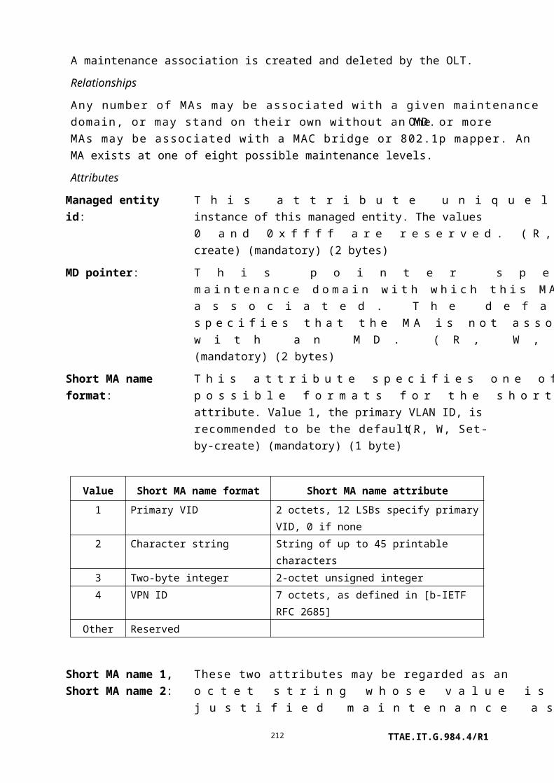
Ip static route table: This attribute stores static routes. A route contains several fields, defined below.
route id: A unique identifier of a route within the static route table. (1 byte)
action: Remove (0) or add (1) this route, meaningful during the set action only. When a static route is being removed, the route is identified by the route id field. (1 byte)
destination The IP destination address of this route. This field address: may be set to the default route address 0.0.0.0. (4 bytes)
destination The address mask associated with the destination address mask: address. (4 bytes)
next hop: The address of the next router on remote routes. This field is not used when the next hop is reached through an unnumbered link. (4 bytes, 0xFFFF FFFF when not used)
output port: The number of the IP port through which the next hop should be reached. This field is used when the next hop is reached through an unnumbered link and when a static route is set to support a fully meshed network. (1 byte, 0xFF when not used)
iw pointer: Pointer to the instance of the GEM interworking termination point that identifies a link of a fully meshed network being set by this attribute. The value 0 is a null pointer. (2 bytes)
metric: The routing metric for this route. (4 bytes)
(R, W) (mandatory) (21N bytes, where N is the number of routes)
Actions
Get, get next, set
Notifications
TTAE.IT.G.984.4/R1212

None.
9.4.6 IP router performance monitoring history data 1
This managed entity collects some of the IP-related performance monitoring data at an IP router. Instances of this managed entity are created and deleted by the OLT.
For a complete discussion of generic PM architecture, refer to clause I.1.9.
Relationships
An instance of this managed entity is associated with an instance of the IP router service profile.
Attributes
Managed entity id: This attribute uniquely identifies each instance of this managed entity. Through an identical ID, this managed entity is implicitly linked to an instance of the IP router service profile. (R, Set-by-create) (mandatory) (2 bytes)
Interval end time: This attribute identifies the most recently finished 15-minute interval. (R) (mandatory) (1 byte)
Threshold data 1/2 id: This attribute points to an instance of the threshold data 1 and 2 managed entities that contains PM threshold values. (R, W, Set-by-create) (mandatory) (2 bytes)
Ip in receives counter: This attribute counts packets received from interfaces, including those with errors. (R) (mandatory) (4 bytes)
Ip in hdr errors counter:
This attribute counts packets discarded due to errors in their IP headers, including bad checksums, version number mismatch, other format errors, time-to-live exceeded, errors discovered in processing IP options, etc. (R) (mandatory) (4 bytes)
Ip in addr errors counter:
This attribute counts packets discarded because their destination IP addresses were not valid for this router. This includes invalid addresses (e.g., 0.0.0.0) and addresses of unsupported classes (e.g., class E). (R) (mandatory) (4 bytes)
Ip forw packets counter:This attribute counts packets whose final IP destination was not this router, as a result of which an attempt was made to forward them. (R) (mandatory) (4 bytes)
Ip in unknown protos counter:
This attribute counts packets that were locally destined and received successfully but discarded because of an unknown or unsupported protocol. (R) (mandatory) (4 bytes)
TTAE.IT.G.984.4/R1213

Ip in discards counter: This attribute counts input packets for which no problems were encountered to prevent their continued processing, but which were nevertheless discarded, e.g., for lack of buffer space. It does not include packets discarded while awaiting re-assembly. (R) (mandatory) (4 bytes)
Ip in delivers counter: This attribute counts input packets successfully delivered to local IP application protocols, including ICMP. (R) (mandatory) (4 bytes)
Ip out requests counter: This attribute counts packets originated by local IP application protocols, including ICMP. This does not include packets counted in ip forw packets counter. (R) (mandatory) (4 bytes)
Ip out discards counter: This attribute counts output packets for which no problem was encountered to prevent transmission to their destination, but which were nevertheless discarded, e.g., for lack of buffer space. It includes packets counted in ip forw packets counter if any such packets met this discard criterion. (R) (mandatory) (4 bytes)
Ip out no routes counter:
This attribute counts packets discarded because no forwarding route was available. It includes any packets counted in ip forw packets counter that met this no-route criterion. It also includes packets that a host could not route because all of its default gateways were down. (R) (mandatory) (4 bytes)
Actions
Create, delete, get, set
Get current data (optional)
Notifications
Threshold crossing alert
Number Threshold crossing alert Threshold value attribute # (Note)
0 Ip in receives 1
1 Ip in hdr 2
2 Ip in addr 3
3 Ip forw packets 4
4 Ip in unknown protos 5
5 Ip in discards 6
6 Ip in delivers 7
7 Ip out requests 8
TTAE.IT.G.984.4/R1214

8 Ip out discards 9
9 Ip out no routes 10
NOTE – This number associates the TCA with the specified threshold value attribute of the
threshold data 1/2 managed entities.
9.4.7 IP router performance monitoring history data 2
This managed entity collects additional IP-related performance monitoring data at an IP router. An instance of this managed entity is created and deleted by the OLT.
For a complete discussion of generic PM architecture, refer to clause I.1.9.
Relationships
An instance of this managed entity is associated with an instance of the IP router service profile.
Attributes
Managed entity id: This attribute uniquely identifies each instance of this managed entity. Through an identical ID, this managed entity is implicitly linked to an instance of the IP router service profile. (R, Set-by-create) (mandatory) (2 bytes)
Interval end time: This attribute identifies the most recently finished 15-minute interval. (R) (mandatory) (1 byte)
Threshold data 1/2 id: This attribute points to an instance of the threshold data 1 managed entity that contains PM threshold values. Since no threshold value attribute number exceeds 7, a threshold data 2 ME is optional. (R, W, Set-by-create) (mandatory) (2 bytes)
TTAE.IT.G.984.4/R1215

Ip reasm reqds counter: This attribute counts received packets that needed to be reassembled. (R) (mandatory) (4 bytes)
Ip reasm OKs counter: This attribute counts packets successfully re-assembled. (R) (mandatory) (4 bytes)
Ip reasm fails counter: This attribute counts failures of the IP re-assembly algorithm for any reason: timed out, errors, etc. This is not necessarily a count of discarded IP fragments, since some algorithms (notably the algorithm in [IETF RFC 815]) can lose track of the number of fragments by combining them as they are received. (R) (mandatory) (4 bytes)
Ip frag OKs counter: This attribute counts packets that were successfully fragmented. (R) (mandatory) (4 bytes)
Ip frag fails counter: This attribute counts packets that were discarded because they needed to be fragmented but could not be, e.g., because the do not fragment flag was set. (R) (mandatory) (4 bytes)
Ip frag creates counter: This attribute counts IP fragments that were generated as a result of fragmentation. (R) (mandatory) (4 bytes)
Actions
Create, delete, get, set
Get current data (optional)
Notifications
Threshold crossing alert
Number Threshold crossing alert Threshold value attribute # (Note)
0 Ip reasm reqds 1
1 Ip reasm OKs 2
2 Ip reasm fails 3
3 Ip frag OKs 4
4 Ip frag fails 5
5 Ip frag creates 6
NOTE – This number associates the TCA with the specified threshold value attribute of the
threshold data 1 managed entity.
9.4.8 ICMP performance monitoring history data 1
This managed entity contains performance monitoring related to received ICMP messages at an IP router. An instance of this managed entity is created and deleted by the OLT.
TTAE.IT.G.984.4/R1216

For a complete discussion of generic PM architecture, refer to clause I.1.9.
Relationships
An instance of this managed entity is associated with an instance of the IP router service profile.
Attributes
Managed entity id: This attribute uniquely identifies each instance of this managed entity. Through an identical ID, this managed entity is implicitly linked to an instance of the IP router service profile. (R, Set-by-create) (mandatory) (2 bytes)
Interval end time: This attribute identifies the most recently finished 15-minute interval. (R) (mandatory) (1 byte)
Threshold data 1/2 id: This attribute points to an instance of the threshold data 1 and 2 managed entities that contains PM threshold values. (R, W, Set-by-create) (mandatory) (2 bytes)
Icmp in msgs counter: This attribute counts received ICMP messages. It includes those also counted by icmp in errors counter. (R) (mandatory) (4 bytes)
Icmp in errors counter: This attribute counts ICMP messages that were received but had ICMP-specific errors: bad ICMP checksums, bad length, etc. (R) (mandatory) (4 bytes)
Icmp in dest unreachs counter:
This attribute counts received ICMP destination unreachable messages. (R) (mandatory) (4 bytes)
Icmp in time excds counter:
This attribute counts received ICMP time exceeded messages. (R) (mandatory) (4 bytes)
Icmp in parm probs counter:
This attribute counts received ICMP parameter problem messages. (R) (mandatory) (4 bytes)
Icmp in src quenchs counter:
This attribute counts received ICMP source quench messages. (R) (mandatory) (4 bytes)
Icmp in redirects counter:
This attribute counts received ICMP redirect messages. (R) (mandatory) (4 bytes)
TTAE.IT.G.984.4/R1217

Icmp in echos counter: This attribute counts received ICMP echo (request) messages. (R) (mandatory) (4 bytes)
Icmp in echo reps counter:
This attribute counts received ICMP echo reply messages. (R) (mandatory) (4 bytes)
Icmp in timestamps counter:
This attribute counts received ICMP timestamp (request) messages. (R) (mandatory) (4 bytes)
Icmp in timestamp reps counter:
This attribute counts received ICMP timestamp reply messages. (R) (mandatory) (4 bytes)
Icmp in addr masks counter:
This attribute counts received ICMP address mask (request) messages. (R) (mandatory) (4 bytes)
Icmp in addr mask reps counter:
This attribute counts received ICMP address mask reply messages. (R) (mandatory) (4 bytes)
Actions
Create, delete, get, set
Get current data (optional)
Notifications
Threshold crossing alert
Number Threshold crossing alert Threshold value attribute # (Note)
0 Icmp in msgs 1
1 Icmp in errors 2
2 Icmp in dest unreachs 3
3 Icmp in time excds 4
4 Icmp in parm probs 5
5 Icmp in src quenchs 6
6 Icmp in redirects 7
7 Icmp in echos 8
8 Icmp in timestamps 9
9 Icmp in timestamp reps 10
10 Icmp in addr masks 11
11 Icmp in addr mask reps 12
NOTE – This number associates the TCA with the specified threshold value attribute of the
threshold data 1/2 managed entities.
TTAE.IT.G.984.4/R1218

9.4.9 ICMP performance monitoring history data 2
This managed entity contains performance monitoring related to transmitted ICMP messages at an IP router. An instance of this managed entity is created and deleted by the OLT.
For a complete discussion of generic PM architecture, refer to clause I.1.9.
Relationships
An instance of this managed entity is associated with an instance of the IP router service profile.
Attributes
Managed entity id: This attribute uniquely identifies each instance of this managed entity. Through an identical ID, this managed entity is implicitly linked to an instance of the IP router service profile. (R, Set-by-create) (mandatory) (2 bytes)
Interval end time: This attribute identifies the most recently finished 15-minute interval. (R) (mandatory) (1 byte)
Threshold data 1/2 id: This attribute points to an instance of the threshold data 1 and 2 managed entities that contains PM threshold values. (R, W, Set-by-create) (mandatory) (2 bytes)
Icmp out msgs counter: This attribute counts ICMP messages that this router attempted to send. It includes those also counted by icmp out errors counter. (R) (mandatory) (4 bytes)
Icmp out errors counter: This attribute counts ICMP messages that this router did not send due to problems within ICMP, such as a lack of buffers. This value should not include errors outside the ICMP layer such as the inability of IP to route the resultant packet. In some implementations, there may be no types of error that contribute to this counter. (R) (mandatory) (4 bytes)
TTAE.IT.G.984.4/R1219
Icmp out dest unreachs counter:
This attribute counts transmitted ICMP destination unreachable messages. (R) (mandatory) (4 bytes)
Icmp out time excds counter:
This attribute counts transmitted ICMP time exceeded messages. (R) (mandatory) (4 bytes)
Icmp out parm probs counter:
This attribute counts transmitted ICMP parameter problem messages. (R) (mandatory) (4 bytes)
Icmp out src quenchs counter:
This attribute counts transmitted ICMP source quench messages. (R) (mandatory) (4 bytes)
Icmp out redirects counter:
This attribute counts transmitted ICMP redirect messages. (R) (mandatory) (4 bytes)
Icmp out echos counter: This attribute counts transmitted ICMP echo (request) messages. (R) (mandatory) (4 bytes)
Icmp out echo reps counter:
This attribute counts transmitted ICMP echo reply messages. (R) (mandatory) (4 bytes)
Icmp out timestamps counter:
This attribute counts transmitted ICMP timestamp (request) messages. (R) (mandatory) (4 bytes)
Icmp out timestamp reps counter:
This attribute counts transmitted ICMP timestamp reply messages. (R) (mandatory) (4 bytes)
Icmp out addr masks counter:
This attribute counts transmitted ICMP address mask (request) messages. (R) (mandatory) (4 bytes)
Icmp out addr mask reps counter:
This attribute counts transmitted ICMP address mask reply messages. (R) (mandatory) (4 bytes)
Actions
Create, delete, get, set
Get current data (optional)
Notifications
Threshold crossing alert
Number Threshold crossing alert Threshold value attribute # (Note)
0 Icmp out msgs 11 Icmp out errors 22 Icmp out dest unreachs 33 Icmp out time excds 44 Icmp out parm probs 55 Icmp out src quenchs 6
TTAE.IT.G.984.4/R1220

6 Icmp out redirects 77 Icmp out echos 88 Icmp out timestamps 99 Icmp out timestamp reps 10
10 Icmp out addr masks 1111 Icmp out addr mask reps 12
NOTE – This number associates the TCA with the specified threshold value attribute of the threshold data 1/2 managed entities.
9.4.10 ARP service profile
This managed entity organizes data associated with the ARP function used by an IP router. The OLT creates or deletes an instance of this managed entity upon the creation or deletion of the corresponding instance of IP port configuration data of native LAN type.
Relationships
An instance of this managed entity is associated with one instance of IP port configuration data of native LAN type. The actual content of a port's ARP cache is visible through the implicitly linked ARP configuration data ME.
Attributes
Managed entity id: This attribute uniquely identifies each instance of this managed entity. This two-byte number indicates the physical position of the slot id (defined in clause 9.1.5). It is 0 if the ONT is integrated. The second byte is assigned by the OLT in the range 1..255. (R, Set-by-create) (mandatory) (2 bytes)
ARP timer: This attribute reports the maximum number of seconds that IP packets are held while they are awaiting address resolution by ARP at this port. (R) (mandatory) (4 bytes)
ARP cache clear: The Boolean value true initializes the associated ARP cache. The value false has no significance. As the value of this attribute has no physical meaning, the get action always returns the value false. (R, W) (mandatory) (1 byte)
Actions
Create, delete, get, set
Notifications
None.
TTAE.IT.G.984.4/R1221

9.4.11 ARP configuration data
This managed entity organizes data associated with the ARP function related to an IP router. The ONT automatically creates or deletes an instance of this managed entity upon creation or deletion of an associated ARP service profile.
Relationships
An instance of this managed entity is associated with an instance of the ARP service profile.
Attributes
Managed entity id: This attribute uniquely identifies each instance of this managed entity. Through an identical ID, this managed entity is implicitly linked to an instance of the ARP service profile. (R) (mandatory) (2 bytes)
ARP table max size: This attribute defines the maximum number of ARP entries that can be stored in the ARP table. Its value is determined by the ONT implementation. (R) (mandatory) (2 bytes)
ARP table: This attribute lists the current entries in the ARP cache. An ARP cache entry contains several fields:
port: The port number of the IP port associated with the entry. (1 byte)
IP address: An IP address. (4 bytes)
MAC address: An equivalent MAC address resolved by the ARP procedure. (6 bytes)
type: The entry type such as dynamic (3) or static (4). (1 byte)
(R) (mandatory) (12N bytes, where N is the number of entries)
Actions
Get, get next
Notifications
None.
9.4.12 IP host config data
The IP host config data configures IP-based services offered on the ONT. The ONT automatically creates instances of this managed entity if IP host services are available.
Relationships
TTAE.IT.G.984.4/R1222

An instance of this managed entity is associated with the ONT managed entity. Any number of TCP/UDP MEs can point to the IP host config data, to model any number of ports and protocols. Performance may be monitored through an implicitly linked IP host PM history data ME.
Attributes
Managed entity id: This attribute uniquely identifies each instance of this managed entity. The ONT creates as many instances as there are independent IP stacks on the ONT. To facilitate discovery by the OLT, IP host config data MEs should be numbered from 0 upward. (R) (mandatory) (2 bytes)
IP options: This attribute is a bit map that enables or disables IP related options. The value 1 enables the option while 0 disables it. The default value of this attribute is 0.
0x01 Enable DHCP0x02 Respond to pings0x04 Respond to traceroute messages0x08 Enable IP stack0x10..0x80 Reserved
(R, W) (mandatory) (1 byte)
Several attributes of this managed entity may be paired together into two categories, manual settings and current values.
While the IP stack is disabled, there is no IP connectivity to the external world from this managed entity instance.
While DHCP is disabled, the current values are always the same as the manual settings. While DHCP is enabled, the current values are those assigned by DHCP, or undefined (0) if DHCP has never assigned values.
MAC address: This attribute indicates the MAC address used by the IP node. (R) (mandatory) (6 bytes)
TTAE.IT.G.984.4/R1
Manual settings Current valuesIP address Current addressMask Current maskGateway Current gatewayPrimary DNS Current primary DNSSecondary DNS Current secondary DNS
223
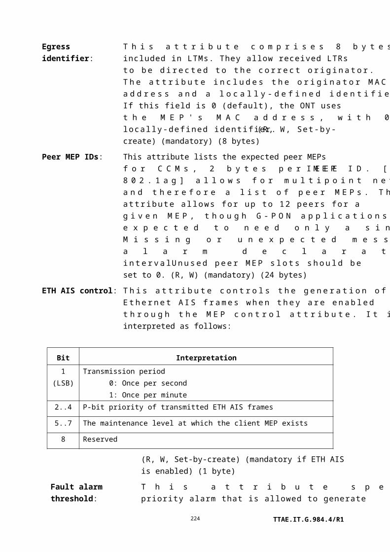
Ont identifier: A unique ONT identifier string. If set to a non-null value, this string is used instead of the MAC address in retrieving DHCP parameters. If the string is shorter than 25 characters, it must be null terminated. Its default value is 25 null bytes. (R, W) (mandatory) (25 bytes)
IP address: The address used for IP host services, this attribute has default value 0. (R, W) (mandatory) (4 bytes)
Mask: The address used for IP host services, this attribute has default value 0. (R, W) (mandatory) (4 bytes)
Gateway: The default gateway address used for IP host services, this attribute has default value 0. (R, W) (mandatory) (4 bytes)
Primary DNS: The address of the primary DNS server, this attribute has default value 0. (R, W) (mandatory) (4 bytes)
Secondary DNS: The address of the secondary DNS server, this attribute has default value 0. (R, W) (mandatory) (4 bytes)
Current address: Current address of the IP host service. (R) (optional) (4 bytes)
Current mask: Current subnet mask for the IP host service. (R) (optional) (4 bytes)
Current gateway: Current default gateway address for the IP host service. (R) (optional) (4 bytes)
Current primary DNS: Current primary DNS server address. (R) (optional) (4 bytes)
Current secondary DNS: Current secondary DNS server address. (R) (optional) (4 bytes)
Domain name: If DHCP indicates a domain name, it is presented here. If no domain name is indicated, this attribute is set to a null string. If the string is shorter than 25 bytes, it must be null terminated. The default value is 25 null bytes. (R) (mandatory) (25 bytes)
Host name: If DHCP indicates a host name, it is presented here. If no host name is indicated, this attribute is set to a null string. If the string is shorter than 25 bytes, it must be null terminated. The default value is 25 null bytes. (R) (mandatory) (25 bytes)
Actions
TTAE.IT.G.984.4/R1224
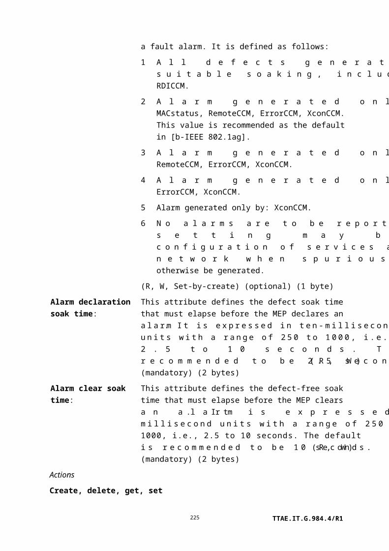
Get, set
Test: Invoke an ICMP message from this IP host. The test message can be configured to generate a ping or traceroute. Appendix II defines the test, test response and test result messages.
Notifications
Attribute value change
Number Attribute value change Description
1..8 N/A
9 Current address The new value assigned via DHCP
10 Current mask The new value assigned via DHCP
11 Current gateway The new value assigned via DHCP
12 Current primary DNS The new value assigned via DHCP
13 Current secondary DNS The new value assigned via DHCP
14 Domain name The new value assigned via DHCP
15 Host name The new value assigned via DHCP
16 Reserved
9.4.13 IP host performance monitoring history data
This managed entity collects performance monitoring data related to an IP host. Instances of this managed entity are created and deleted by the OLT.
For a complete discussion of generic PM architecture, refer to clause I.1.9.
Relationships
An instance of this managed entity is associated with an instance of the IP host managed entity.
Attributes
Managed entity id: This attribute uniquely identifies each instance of this managed entity. Through an identical ID, this managed entity is implicitly linked to an instance of the IP host configuration data ME. (R, Set-by-create) (mandatory) (2 bytes)
Interval end time: This attribute identifies the most recently finished 15-minute interval. (R) (mandatory) (1 byte)
Threshold data 1/2 id: This attribute points to an instance of the threshold data 1 managed entity that contains PM threshold values. Since no threshold value attribute number exceeds 7, a threshold data 2 ME is optional. (R, W, Set-by-create) (mandatory) (2 bytes)
TTAE.IT.G.984.4/R1225
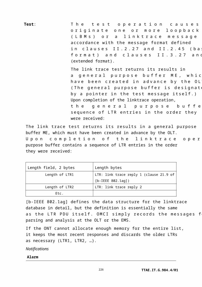
ICMP errors: This attribute counts ICMP errors received. (R) (mandatory) (4 bytes)
DNS errors: This attribute counts DNS errors received. (R) (mandatory) (4 bytes)
Actions
Create, delete, get, set
Get current data (optional)
Notifications
Threshold crossing alert
Number Threshold crossing alert Threshold value attribute # (Note)
0 N/A
1 IPNPM ICMP error 1
2 IPNPM DNS error 2
NOTE – This number associates the TCA with the specified threshold value attribute of the
threshold data 1 managed entity.
9.4.14 TCP/UDP config data
The TCP/UDP config data managed entity contains the configuration for TCP- and UDP-based services that are offered from an IP host. If a non-OMCI interface is used to manage an IP service, this ME is unnecessary. The non-OMCI interface supplies the necessary data.
An instance of this managed entity is created and deleted on request of the OLT.
Relationships
One or more instances of this managed entity may be associated with an instance of an IP host config data managed entity.
Attributes
TTAE.IT.G.984.4/R1226

Managed entity id: This attribute uniquely identifies each instance of this managed entity. It is recommended that the managed entity id be the same as the port number. (R, Set-by-create) (mandatory) (2 bytes)
Port id: This attribute specifies the port number that offers the TCP/UDP service. (R, W, Set-by-create) (mandatory) (2 bytes)
Protocol: This attribute specifies the protocol type as defined by IANA. The default value is UDP (0x11) (R, W, Set-by-create) (mandatory) (1 byte)
TOS/diffserv field: This attribute specifies the value of the TOS/diffserv field of the IPv4 header. The contents of this attribute may contain the type of service per [IETF RFC 1349] or a differentiated services code point (DSCP). Valid values for DSCP are as defined by IANA. The default value is 0. (R, W, Set-by-create) (mandatory) (1 byte)
IP host pointer: This attribute points to the IP host config data ME associated with this TCP/UDP data. Any number of ports and protocols may be associated with an IP host. (R, W, Set-by-create) (mandatory) (2 bytes)
Actions
Create, delete, get, set
Notifications
None.
9.5 Ethernet services
This clause defines managed entities associated with physical and virtual Ethernet UNIs, as shown in Figure 9.5-1.
Figure 9.5-1 – Managed entities associated with physical Ethernet UNIs
TTAE.IT.G.984.4/R1227

9.5.1 Physical path termination point Ethernet UNI
This managed entity represents the point at an Ethernet UNI where the physical path terminates and Ethernet physical level functions are performed.
The ONT automatically creates an instance of this managed entity per port:
• When the ONT has Ethernet ports built into its factory configuration.
• When a cardholder is provisioned to expect a circuit pack of Ethernet type.
• When a cardholder provisioned for plug-and-play is equipped with a circuit pack of Ethernet type. Note that the installation of a plug-and-play card may indicate the presence of Ethernet ports via equipment ID as well as its type, and indeed may cause the ONT to instantiate a port mapping package that specifies Ethernet ports.
The ONT automatically deletes instances of this managed entity when a cardholder is neither provisioned to expect an Ethernet circuit pack, nor is it equipped with an Ethernet circuit pack.
Relationships
An instance of this managed entity is associated with each instance of a preprovisioned or real Ethernet port.
Attributes
Managed entity id: This attribute uniquely identifies each instance of this managed entity. This two-byte number indicates the physical position of the UNI. The first byte is the slot id (defined in clause 9.1.5). The second byte is the port ID, with range 1..255. (R) (mandatory) (2 bytes)
Expected type: This attribute supports pre-provisioning. It is coded as follows:
0 Autosense.1 to 254 One of the values from Table 9.1.5-1 that is
compatible with an Ethernet circuit pack.
Upon ME instantiation, the ONT sets this attribute to 0. (R, W) (mandatory) (1 byte)
Sensed type: When a circuit pack is present, this attribute represents its type as one of the values from Table 9.1.5-1. If the value of expected type is not 0, then the value of sensed type should be the same as the value of expected type. Upon ME instantiation, the ONT sets this attribute to 0. See also the note in the notifications below.
(R) (mandatory if the ONT supports circuit packs with configurable interface types, e.g., 10/100 BaseT card) (1 byte)
TTAE.IT.G.984.4/R1228

Auto detection configuration:
This attribute sets the Ethernet port configuration:
Codepoint Rate Duplex
0x00 Auto Auto
0x01 10 only Full duplex only
0x02 100 only Full duplex only
0x03 1000 only Full duplex only
0x04 Auto Full duplex only
0x10 10 only Auto
0x11 10 only Half duplex only
0x12 100 only Half duplex only
0x13 1000 only Half duplex only
0x14 Auto Half duplex only
0x20 1000 only Auto
0x30 100 only Auto
Upon ME instantiation, the ONT sets this attribute to 0. (R, W) (mandatory for interfaces with auto detection options) (1 byte)
Ethernet loopback configuration:
This attribute sets the Ethernet loopback configuration:
0 No loopback.
3 Loop 3, loopback of downstream traffic after PHY transceiver. Loop 3 is depicted in Figure 9.5.1-5.
Note that normal bridge behaviour may defeat the loopback signal, unless broadcast MAC addresses are used. Upon ME instantiation, the ONT sets this attribute to 0. (R, W) (mandatory) (1 byte)
Figure 9.5.1-1 – Ethernet loopback configuration
Administrative state: This attribute locks (1) and unlocks (0) the functions performed
TTAE.IT.G.984.4/R1229

by this managed entity. When the administrative state is set to lock, all user functions of this UNI are blocked, and alarms, TCAs and AVCs for this managed entity and all dependent managed entities are no longer generated. Selection of a default value for this attribute is outside the scope of this Recommendation. (R, W) (mandatory) (1 byte)
Operational state: This attribute indicates whether or not the managed entity is capable of performing its function. Valid values are enabled (0) and disabled (1). (R) (optional) (1 byte)
Configuration ind: This attribute indicates the configuration status of the Ethernet UNI.
0x01 10BaseT full duplex.0x02 100BaseT full duplex.0x03 Gigabit Ethernet full duplex.0x11 10BaseT half duplex.0x12 100BaseT half duplex.0x13 Gigabit Ethernet half duplex.
The value 0 indicates that the configuration status is unknown (e.g., Ethernet link is not established or the circuit pack is not yet installed). Upon ME instantiation, the ONT sets this attribute to 0. (R) (mandatory) (1 byte)
Max frame size: This attribute denotes the maximum frame size allowed across this interface. Upon ME instantiation, the ONT sets the attribute to 1518. (R, W) (mandatory for G-PON, optional for GbE) (2 bytes)
DTE or DCE ind: This attribute specifies the Ethernet interface wiring:
0 DCE or MDI-X (default).1 DTE or MDI.2 Automatic selection
(R, W) (mandatory) (1 byte)
Pause time: This attribute allows the PPTP to ask the subscriber terminal to temporarily suspend sending data. Units are in pause quanta (1 pause quantum is 512 bit times of the particular implementation). Values: 0..0xFFFF. Upon ME instantiation, the ONT sets this attribute to 0. (R, W) (optional) (2 bytes)
Bridged or IP ind: This attribute specifies whether the Ethernet interface is bridged
TTAE.IT.G.984.4/R1230

or derived from an IP router function0 Bridged.1 IP router.2 Depends on the parent circuit pack. 2 means that the circuit
pack's bridged or IP ind attribute is either 0 or 1.
Upon ME instantiation, the ONT sets this attribute to 2. (R, W) (optional) (1 byte)
ARC: See clause I.1.8. (R, W) (optional) (1 byte)
ARC interval: See clause I.1.8. (R, W) (optional) (1 byte)
PPPoE filter: This attribute controls filtering of PPPoE packets on this Ethernet port. The value 0 allows packets of all types. The value 1 discards everything but PPPoE packets. The default value is 0. (R, W) (optional) (1 byte)
Power control: This attribute controls whether power is provided to an external equipment over the Ethernet PPTP. The value 1 enables power over the Ethernet port. The default value 0 disables power feed. (R, W) (optional) (1 byte)
Actions
Get, set
Notifications
Attribute value change
Number Attribute value change Description
1 N/A
2 Sensed type Sensed type of Ethernet interface. Valid values are 1
(10BaseT), 2 (100BaseT) and 3 (Gigabit Ethernet)
(Note).
3..5 N/A
6 Op state Operational state
7..11 N/A
12 ARC ARC timer expiration
13..15 N/A
16 Reserved
TTAE.IT.G.984.4/R1231

NOTE – These values violate the rules of the AVC message, which require the changed value of
the sensed type (in this case) attribute to be reported. Because of existing implementations, pre-
existing documentation is retained; however, implementers should regard this attribute and its
AVC with caution.
Alarm
Number Alarm Description
0 LAN-LOS No carrier at the Ethernet UNI
1..207 Reserved
208..223 Vendor-specific alarms Not to be standardized
9.5.2 Ethernet performance monitoring history data
This managed entity collects some of the performance monitoring data for an Ethernet interface. Instances of this managed entity are created and deleted by the OLT.
For a complete discussion of generic PM architecture, refer to clause I.1.9.
Relationships
An instance of this managed entity is associated with an instance of the physical path termination point Ethernet UNI.
Attributes
Managed entity id: This attribute uniquely identifies each instance of this managed entity. Through an identical ID, this managed entity is implicitly linked to an instance of the physical path termination point Ethernet UNI. (R, Set-by-create) (mandatory) (2 bytes)
Interval end time: This attribute identifies the most recently finished 15-minute interval. (R) (mandatory) (1 byte)
Threshold data 1/2 id: This attribute points to an instance of the threshold data 1 and 2 managed entities that contains PM threshold values. (R, W, Set-by-create) (mandatory) (2 bytes)
TTAE.IT.G.984.4/R1232

FCS errors: This attribute counts frames received on a particular interface that were an integral number of octets in length but failed the frame check sequence (FCS) check. The count is incremented when the MAC service returns the frameCheckError status to the link layer control (LLC) or other MAC user. Received frames for which multiple error conditions are obtained are counted according to the error status presented to the LLC. (R) (mandatory) (4 bytes)
Excessive collision counter:
This attribute counts frames whose transmission failed due to excessive collisions. (R) (mandatory) (4 bytes)
Late collision counter: This attribute counts the number of times that a collision was detected later than 512 bit times into the transmission of a packet. (R) (mandatory) (4 bytes)
Frames too long: This attribute counts received frames that exceeded the maximum permitted frame size. The count is incremented when the MAC service returns the frameTooLong status to the LLC. (R) (mandatory) (4 bytes)
Buffer overflows on receive:
This attribute counts the number of times that the receive buffer overflowed. (R) (mandatory) (4 bytes)
Buffer overflows on transmit:
This attribute counts the number of times that the transmit buffer overflowed. (R) (mandatory) (4 bytes)
Single collision frame counter:
This attribute counts successfully transmitted frames whose transmission was delayed by exactly one collision. (R) (mandatory) (4 bytes)
Multiple collisions frame counter:
This attribute counts successfully transmitted frames whose transmission was delayed by more than one collision. (R) (mandatory) (4 bytes)
SQE counter: This attribute counts the number of times that the SQE test error message was generated by the PLS sublayer. (R) (mandatory) (4 bytes)
Deferred transmission counter:
This attribute counts frames whose first transmission attempt was delayed because the medium was busy. The count does not include frames involved in collisions. (R) (mandatory) (4 bytes)
Internal MAC transmit error counter:
This attribute counts frames whose transmission failed due to an internal MAC sublayer transmit error. (R) (mandatory) (4 bytes)
Carrier sense error This attribute counts the number of times that carrier sense was
TTAE.IT.G.984.4/R1233

counter: lost or never asserted when attempting to transmit a frame. (R) (mandatory) (4 bytes)
Alignment error counter:This attribute counts received frames that were not an integral number of octets in length and did not pass the FCS check. (R) (mandatory) (4 bytes)
Internal MAC receive error counter:
This attribute counts frames whose reception failed due to an internal MAC sublayer receive error. (R) (mandatory) (4 bytes)
Actions
Create, delete, get, set
Get current data (optional)
Notifications
Threshold crossing alert
Number Threshold crossing alert Threshold value attribute # (Note)
0 FCS errors 1
1 Excessive collision counter 2
2 Late collision counter 3
3 Frames too long 4
4 Buffer overflows on receive 5
5 Buffer overflows on transmit 6
6 Single collision frame counter 7
7 Multiple collisions frame counter 8
8 SQE counter 9
9 Deferred transmission counter 10
10 Internal MAC transmit error counter 11
11 Carrier sense error counter 12
12 Alignment error counter 13
13 Internal MAC receive error counter 14
NOTE – This number associates the TCA with the specified threshold value attribute of the
threshold data 1/2 managed entities.
9.5.3 Ethernet performance monitoring history data 2
This managed entity collects additional performance monitoring data for an Ethernet interface. Instances of this managed entity are created and deleted by the OLT.
For a complete discussion of generic PM architecture, refer to clause I.1.9.
Relationships
TTAE.IT.G.984.4/R1234

An instance of this Ethernet performance monitoring history data 2 managed entity is associated with an instance of the physical path termination point Ethernet UNI.
Attributes
Managed entity id: This attribute uniquely identifies each instance of this managed entity. Through an identical ID, this managed entity is implicitly linked to an instance of the physical path termination point Ethernet UNI. (R, Set-by-create) (mandatory) (2 bytes)
Interval end time: This attribute identifies the most recently finished 15-minute interval. (R) (mandatory) (1 byte)
Threshold data 1/2 id: This attribute points to an instance of the threshold data 1 managed entity that contains PM threshold values. Since no threshold value attribute number exceeds 7, a threshold data 2 ME is optional. (R, W, Set-by-create) (mandatory) (2 bytes)
PPPoE filtered frame counter:
This attribute counts the number of frames discarded due to PPPoE filtering. (R) (mandatory) (4 bytes)
Actions
Create, delete, get, set
Get current data (optional)
Notifications
Threshold crossing alert
Number Threshold crossing alert Threshold value attribute # (Note)
0 PPPoE filtered frame counter 1
NOTE – This number associates the TCA with the specified threshold value attribute of the threshold data
1 managed entity.
9.5.4 Ethernet performance monitoring history data 3
This managed entity collects performance monitoring data associated with an Ethernet interface. It includes parameters defined in the Ethernet statistics group of [b-IETF RFC 2819] that are not already covered by previously defined Ethernet monitoring MEs. The received direction is from the CPE toward the network (upstream).
Instances of this managed entity are created and deleted by the OLT.
For a complete discussion of generic PM architecture, refer to clause I.1.9.
Relationships
TTAE.IT.G.984.4/R1235
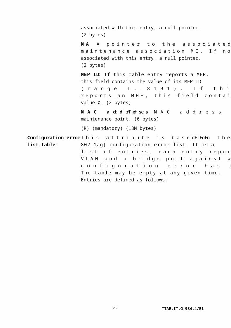
An instance of this managed entity is associated with an instance of the physical path termination point Ethernet UNI.
Attributes
Managed entity id: This attribute uniquely identifies each instance of this managed entity. Through an identical ID, this managed entity is implicitly linked to an instance of the PPTP Ethernet UNI. (R, Set-by-create) (mandatory) (2 bytes)
Interval end time: This attribute identifies the most recently finished 15-minute interval. (R) (mandatory) (1 byte)
Threshold data 1/2 id: This attribute points to an instance of the threshold data 1 managed entity that contains PM threshold values. Since no threshold value attribute number exceeds 7, a threshold data 2 ME is optional. (R, W, Set-by-create) (mandatory) (2 bytes)
Drop events: The total number of events in which packets were dropped due to lack of resources. This is not necessarily the number of packets dropped; it is the number of times this event was detected. (R) (mandatory) (4 bytes)
Octets: The total number of octets received from the CPE, including those in bad packets, excluding framing bits, but including FCS. (R) (mandatory) (4 bytes)
Packets: The total number of packets received, including bad packets, broadcast packets and multicast packets. (R) (mandatory) (4 bytes)
Broadcast packets: The total number of received good packets directed to the broadcast address. This does not include multicast packets. (R) (mandatory) (4 bytes)
Multicast packets: The total number of received good packets directed to a multicast address. This does not include broadcast packets. (R) (mandatory) (4 bytes)
Undersize packets: The total number of packets received that were less than 64 octets long but were otherwise well formed (excluding framing bits, but including FCS octets). (R) (mandatory) (4 bytes)
Fragments: The total number of packets received that were less than 64 octets long, excluding framing bits but including FCS octets, and had either a bad frame check sequence (FCS) with an integral number of octets (FCS error) or a bad FCS with a non-
TTAE.IT.G.984.4/R1236

integral number of octets (alignment error). It is entirely normal for this attribute to increment. This is because it counts both runts (which are normal occurrences due to collisions) and noise hits. (R) (mandatory) (4 bytes)
Jabbers: The total number of packets received that were longer than 1518 octets, excluding framing bits but including FCS octets, and had either a bad frame check sequence (FCS) with an integral number of octets (FCS error) or a bad FCS with a non-integral number of octets (alignment error). The range to detect jabber is between 20 ms and 150 ms. (R) (mandatory) (4 bytes)
Packets 64 octets: The total number of received packets (including bad packets) that were 64 octets long, excluding framing bits but including FCS. (R) (mandatory) (4 bytes)
Packets 65 to 127 octets: The total number of received packets (including bad packets) that were 65..127 octets long, excluding framing bits but including FCS. (R) (mandatory) (4 bytes)
Packets 128 to 255 octets: The total number of packets (including bad packets) received that were 128..255 octets long, excluding framing bits but including FCS. (R) (mandatory) (4 bytes)
Packets 256 to 511 octets: The total number of packets (including bad packets) received that were 256..511 octets long, excluding framing bits but including FCS. (R) (mandatory) (4 bytes)
Packets 512 to 1023 octets: The total number of packets (including bad packets) received that were 512..1023 octets long, excluding framing bits but including FCS. (R) (mandatory) (4 bytes)
Packets 1024 to 1518 octets:The total number of packets (including bad packets) received that were 1024..1518 octets long, excluding framing bits but including FCS. (R) (mandatory) (4 bytes)
Actions
Create, delete, get, set
Get current data (optional)
Notifications
Threshold crossing alert
Number Threshold crossing alert Threshold data counter # (Note)
TTAE.IT.G.984.4/R1237

0 Drop events 1
1 Undersize packets 2
2 Fragments 3
3 Jabbers 4
NOTE – This number associates the TCA with the specified threshold value attribute of the
threshold data 1 managed entity.
9.5.5 Virtual Ethernet interface point
This managed entity represents the data plane hand-off point in an ONT or ONU to a separate (non-OMCI) management domain. The virtual Ethernet interface point is managed by OMCI, and is potentially known to the non-OMCI management domain. One or more Ethernet traffic flows are present at this boundary.
Instances of this managed entity are automatically created and deleted by the ONT. This is necessary because the required downstream priority queues are subject to physical implementation constraints. The OLT may use one or more of the virtual Ethernet interface points created by the ONT.
It is expected that the ONT would create one virtual Ethernet interface point for each non-OMCI management domain.
Relationships
An instance of this managed entity is associated with an instance of a virtual Ethernet interface between OMCI and non-OMCI management domains.
Attributes
Managed entity id: This attribute uniquely identifies each instance of this managed entity. To facilitate easy discovery, the ONT should assign IDs in the sequence 1, 2, …. The values 0 and 0xFFFF are reserved. (R) (mandatory) (2 bytes)
Administrative state:
This attribute locks (1) and unlocks (0) the functions performed by this managed entity. When the administrative state is set to lock, all user functions of this UNI are blocked, and alarms, TCAs and AVCs for this managed entity and all dependent managed entities are no longer generated. (R, W) (mandatory) (1 byte)
Operational state: This attribute indicates whether or not the managed entity is capable of performing its function. Valid values are enabled (0) and disabled (1). (R) (optional) (1 byte)
Inter-domain name: This attribute is a character string that provides an optional way to
TTAE.IT.G.984.4/R1238

identify the virtual Ethernet interface point to a non-OMCI management domain. The interface may also be identified by its managed entity ID, IANA assigned port and possibly other ways. If the vendor offers no information in this attribute, it should be set to a sequence of null bytes. (R, W) (optional) (25 bytes)
TCP/UDP pointer: This attribute points to an instance of the TCP/UDP config data managed entity, which provides for OMCI management of the non-OMCI management domain's IP connectivity. If no OMCI management of the non-OMCI domain's IP connectivity is required, this attribute may be omitted or set to its default, a null pointer. (R, W) (optional) (2 bytes)
IANA assigned port: This attribute contains the TCP or UDP port value, as assigned by IANA for the management protocol associated with this virtual Ethernet interface. This attribute is to be regarded as a hint, not as a requirement that management communications use this port; the actual port and protocol are specified in the associated TCP/UDP config data managed entity. If no port has been assigned, or if the management protocol is free to be chosen at run-time, this attribute should be set to 0xFFFF. (R) (mandatory) (2 bytes)
Actions
Get, set
Notifications
Attribute value change
Number Attribute value change Description
0..1 N/A
2 Op state Operational state
3 N/A
4..16 Reserved
Alarm
Number Alarm Description
0 Connecting function fail Indicates a failure of the connecting function. May be
used to signal faults from the non-OMCI management
domain into OMCI.
TTAE.IT.G.984.4/R1239

1..207 Reserved
208..223 Vendor specific alarms Not to be standardized
9.6 802.11 services
This clause defines managed entities associated with physical [IEEE 802.11] UNIs, as shown in Figure 9.6-1.
Figure 9.6-1 – Managed entities associated with physical IEEE 802.11 UNI
All 802.11 UNIs supported by an ONT are implicitly grouped together into an implied diversity group. The model makes no provision to create more than one diversity group on a single ONT.
9.6.1 Physical path termination point 802.11 UNI
This managed entity models an 802.11 UNI, where physical paths terminate and physical path level functions are performed.
The ONT automatically creates an instance of this managed entity per port:
• When the ONT has 802.11 ports built into its factory configuration.
• When a cardholder is provisioned to expect a circuit pack of 802.11 type.
• When a cardholder provisioned for plug-and-play is equipped with a circuit pack of 802.11 type. Note that the installation of a plug-and-play card may indicate the presence of 802.11 ports via equipment ID as well as type, and indeed may cause the ONT to instantiate a port mapping package that specifies 802.11 ports.
TTAE.IT.G.984.4/R1240
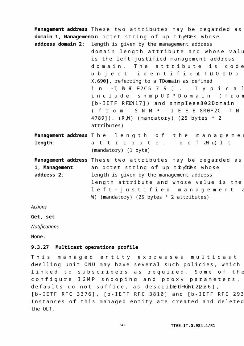
The ONT automatically deletes instances of this managed entity when a cardholder is neither provisioned to expect an 802.11 circuit pack, nor is it equipped with an 802.11 circuit pack.
Relationships
An instance of this managed entity is associated with each instance of an [IEEE 802.11] interface.
Attributes
Managed entity id: This attribute uniquely identifies each instance of this managed entity. This two-byte number indicates the physical position of the UNI. The first byte is the slot id (defined in clause 9.1.5). If the UNI is integrated, this value is 0. The second byte is the port ID, with range 1..255. (R) (mandatory) (2 bytes)
Administrative state: This attribute locks (1) and unlocks (0) the functions performed by this managed entity. When the administrative state is set to lock, all user functions of this UNI are blocked, and alarms, TCAs and AVCs for this managed entity and all dependent managed entities are no longer generated. Selection of a default value for this attribute is outside the scope of this Recommendation. (R, W) (mandatory) (1 byte)
Operational state: This attribute indicates whether or not the managed entity is capable of performing its function. Valid values are enabled (0) and disabled (1). (R) (optional) (1 byte)
dot11 supported data rates tx:
This attribute specifies the set of data rates (maximum 8) at which the station is capable of transmitting data. Each octet contains a value representing a rate. Each rate lies within the range 2..127, corresponding to data rates in increments of 500 kbit/s from 1 Mbit/s to 63.5 Mbit/s. If fewer than 8 data rates are specified, each of the unused bytes is set to 0. (R) (mandatory) (8 bytes)
dot11 supported data rates rx:
This attribute specifies the set of data rates (maximum 8) at which the station is capable of receiving data. Each octet contains a value representing a rate. Each rate lies within the range 2..127, corresponding to data rates in increments of 500 kbit/s from 1 Mbit/s to 63.5 Mbit/s. If fewer than 8 data rates are specified, each of the unused bytes is set to 0. (R) (mandatory) (8 bytes)
dot11 Tx power levels: This attribute specifies the set of transmit power levels (maximum 8) that the station is capable of using. Each 16-bit word contains a power setting, in units of mW. If fewer than 8 power levels are specified, each of the unused words is set to 0. (R) (mandatory)
TTAE.IT.G.984.4/R1241

(16 bytes)
ARC: See clause I.1.8. (R, W) (optional) (1 byte)
ARC interval: See clause I.1.8. (R, W) (optional) (1 byte)
Actions
Get, set
Notifications
Attribute value change
Number Attribute value change Description
1 N/A
2 Op state Operational state change
3..5 N/A
6 ARC ARC timer expiration
7 N/A
8..16 Reserved
9.6.2 802.11 station management data 1
This managed entity organizes some of the data associated with an 802.11 station. The ONT automatically creates or deletes an instance of this entity when it creates or deletes a PPTP 802.11 UNI instance.
Relationships
An instance of this managed entity is associated with one instance of an [IEEE 802.11] interface.
Attributes
Managed entity id: This attribute uniquely identifies each instance of this managed entity. Through an identical ID, this managed entity is implicitly linked to an instance of the physical path termination point 802.11 UNI. (R) (mandatory) (2 bytes)
dot11 medium occupancy limit:
This attribute specifies the maximum amount of time, in TU, that a point coordinator may control the use of the wireless medium without relinquishing control for long enough to allow at least one instance of DCF access to the medium. The default value of this attribute is 100 TU; the maximum value is 1000. (R, W) (mandatory) (2 bytes)
dot11 CF pollable: The Boolean value true indicates that the STA is able to respond to a CF-poll with a data frame within one SIFS time. The attribute
TTAE.IT.G.984.4/R1242

is false if the STA is not able to respond to a CF-Poll with a data frame within one SIFS time. (R) (mandatory) (1 byte)
dot11 CFP period: The attribute specifies the number of DTIM intervals between the start of CFPs. (R, W) (mandatory) (1 byte)
dot11 CFP max duration:
The attribute specifies the maximum duration of the CFP in TU that may be generated by the PCF. (R, W) (mandatory) (2 bytes)
dot11 authentication response timeout:
This attribute specifies the number of TU that a responding STA should wait for the next frame in the authentication sequence. (R, W) (mandatory) (4 bytes)
dot11 privacy option implemented:
When true, this Boolean attribute indicates that the [IEEE 802.11] WEP option is implemented. The default value of this attribute is false. (R) (mandatory) (1 byte)
dot11 power management mode:
This attribute specifies the power management mode of the STA. When active (0), the station is not in power save mode. Power save mode is specified by 1. (R, W) (mandatory) (1 byte)
dot11 desired SSID1: This attribute contains the first half of the service set ID used in the desired SSID parameter of the most recent MLME_Scan request. This value may be modified by an external management entity and used by the local SME to make decisions about the scanning process. (R, W) (mandatory) (16 bytes)
dot11 desired SSID2: This attribute contains the second half of the service set ID used in the desired SSID parameter of the most recent MLME_Scan request. (R, W) (mandatory) (16 bytes)
dot11 desired BSS type: This attribute specifies the type of BSS the station accepts when scanning for a BSS with which to synchronize. The station filters probe response frames and beacons on the basis of this attribute.0 Infrastructure: The station only synchronizes with a BSS
whose capability information field has the ESS subfield set to 1.
1 Independent: The station only synchronizes with a BSS whose capability information field has the IBSS subfield set to 1.
2 Any: The station may synchronize to either type of BSS.
(R, W) (mandatory) (1 byte)
dot11 operational rate set:
This attribute specifies the set of data rates (maximum 8) at which the station may transmit data. Each octet contains a value representing a rate. Each rate lies within the range 2..127,
TTAE.IT.G.984.4/R1243

corresponding to data rates in increments of 500 kbit/s from 1 Mbit/s to 63.5 Mbit/s. If fewer than 8 data rates are specified, each of the unused bytes is set to 0. This value is reported in transmitted beacon, probe request, probe response, association request, association response, reassociation request and reassociation response frames, and is used to determine whether a BSS with which the station desires to synchronize is suitable. (R, W) (mandatory) (8 bytes)
dot11 beacon period: This attribute specifies the number of TU that a station uses for scheduling beacon transmissions. This value is transmitted in beacon and probe response frames. (R, W) (mandatory) (2 bytes)
dot11 DTIM period: This attribute specifies the number of beacon intervals that elapse between transmission of beacon frames containing a TIM element whose DTIM count field is 0. This value is transmitted in the DTIM period field of beacon frames. (R, W) (mandatory) (1 byte)
dot11 association response timeout:
This attribute specifies the number of TU that a requesting STA should wait for a response to a transmitted association-request MMPDU. (R, W) (mandatory) (4 bytes)
dot11 authentication algorithm:
This attribute indicates all of the authentication algorithms supported by the STAs. The attribute is a bit map, formatted as follows:
0000 0000 0000 0000 0000 0000 0000 00yx, where:0 Reservedx Open system
0 Not supported1 Supported
y Shared key0 Not supported1 Supported
(R) (mandatory) (4 bytes)
TTAE.IT.G.984.4/R1244

dot11 authentication algorithms enable:
This attribute enables or disables the authentication algorithms supported by the STAs. The attribute is a bit map, formatted as follows:
0000 0000 0000 0000 0000 0000 0000 00yx, where0 reservedx Open system
0 Not enabled1 Enabled
y Shared key0 Not enabled1 Enabled
(R, W) (mandatory) (4 bytes)
Actions
Get, set
Notifications
None.
9.6.3 802.11 station management data 2
This managed entity organizes some of the data associated with an 802.11 station. The ONT automatically creates an instance of this entity whenever it creates a PPTP 802.11 UNI instance.
Relationships
An instance of this managed entity is associated with an instance of an [IEEE 802.11] interface.
Attributes
Managed entity id: This attribute uniquely identifies each instance of this managed entity. Through an identical ID, this managed entity is implicitly linked to an instance of the physical path termination point 802.11 UNI. (R) (mandatory) (2 bytes)
dot11 disassociate reason: This attribute records the reason code in the most recently transmitted disassociation frame. If no disassociation frame has been transmitted, the value of this attribute is 0. (R) (mandatory) (2 bytes)
dot11 disassociate station: This attribute records the MAC address from the address
TTAE.IT.G.984.4/R1245

1 field of the most recently transmitted disassociation frame. If no disassociation frame has been transmitted, the value of this attribute is 0. (R) (mandatory) (6 bytes)
dot11 deauthenticate reason: This attribute records the reason code in the most recently transmitted deauthentication frame. If no deauthentication frame has been transmitted, the value of this attribute is 0. (R) (mandatory) (2 bytes)
dot11 deauthenticate station: This attribute records the MAC address from the address 1 field of the most recently transmitted deauthentication frame. If no deauthentication frame has been transmitted, the value of this attribute is 0. (R) (mandatory) (6 bytes)
TTAE.IT.G.984.4/R1246

dot11 authenticate fail status: This attribute records the status code in the most recently transmitted failed authentication frame. If no failed authentication frame has been transmitted, the value of this attribute is 0. (R) (mandatory) (2 bytes)
dot11 authenticate fail station: This attribute records the MAC address from the address 1 field of the most recently transmitted failed authentication frame. If no failed authentication frame has been transmitted, the value of this attribute is 0. (R) (mandatory) (6 bytes)
The four following attributes contain WEP default keys 1..4, respectively. For security, WEP default secret keys are write-only. The default value of each WEP default key is 0.
dot11 WEP default key value1: (W) (mandatory) (5 bytes)
dot11 WEP default key value2: (W) (mandatory) (5 bytes)
dot11 WEP default key value3: (W) (mandatory) (5 bytes)
dot11 WEP default key value4: (W) (mandatory) (5 bytes)
dot11 privacy invoked and dot11 exclude unencrypted:
This attribute specifies two truth values. It is coded 0b0000 00yx, where x indicates the dot11 privacy invoked value, and y indicates the dot11 exclude unencrypted value.
When dot11 privacy invoked is true, [IEEE 802.11] WEP is used for transmitting data frames. The default value of this attribute is false.
When dot11 exclude unencrypted is true, the STA does not indicate received MSDUs whose WEP subfield of the frame control field is 0 at the MAC service interface. When this value is false, the STA may accept MSDUs whose WEP subfield of the frame control field is 0. The default value of this attribute is false.
(R, W) (mandatory) (1 byte)
dot11 WEP default key ID: When set to values of 0..3, this attribute specifies use of WEP default key 1..4, respectively. The default value is 0. (R, W) (mandatory) (1 byte)
dot11 WEP key mapping length: The maximum number of tuples that dot11 WEP key
TTAE.IT.G.984.4/R1247

mappings can hold. Dot11 WEP key mappings are contained in the 802.11 general purpose object ME, object type 0. (R, W) (mandatory) (4 bytes)
dot11 WEP ICV error count: This counter increments when a frame is received whose frame control field, WEP subfield, is 1, and whose received ICV does not match the ICV value calculated for the frame's contents. (R) (mandatory) (4 bytes)
dot11 WEP excluded count: This counter increments when a frame is received whose WEP subfield of the frame control field is 0, and the value of dot11 exclude unencrypted causes that frame to be discarded. (R) (mandatory) (4 bytes)
Actions
Get, set
Notifications
Attribute value change
Number Attribute value change Description
1 N/A
2 dot11 disassociate station MAC address from the address 1 field of the most
recently transmitted disassociation frame
3 N/A
4 dot11 deauthenticate station MAC address from the address 1 field of the most
recently transmitted deauthentication frame
5 N/A
6 dot11 authenticate fail station MAC address from the address 1 field of the most
recently transmitted failed authentication frame
7..12 N/A
13..16 Reserved
9.6.4 802.11 general purpose object
Relationships
Up to four instances of this managed entity may exist for each instance of an [IEEE 802.11] interface, one of each type. An instance contains one of the following [IEEE 802.11] data types: WEP key mappings, group addresses, supported regulatory domains, and antennas list. Each use has its own attributes, and a type attribute indicates which subset is active for each instance. Regardless of which attributes are active, each attribute is numbered, in the OMCC attribute mask, according to the ordering of the full attribute set indicated below.
TTAE.IT.G.984.4/R1248

For object types 0 and 1, the OLT may create and delete instances of this object. For object types 2 and 3, the ONT creates as many instances as required to model the UNI's capabilities.
Attributes
Managed entity id: This attribute uniquely identifies each instance of this managed entity. When created automatically by the ONT, the ME ID is known to the OLT through out of band means, for example documentation. (R, Set-by-create) (mandatory) (2 bytes)
Object type: This attribute indicates how this entity is used:
0 WEP key mapping.1 Group addresses.2 Reg domain supported.3 Antennas list.
For any given type, only the relevant attributes are valid. The other attributes are unspecified. (R, Set-by-create) (mandatory) (1 byte)
Physical path termination point 802.11 pointer:
This attribute points to the specific physical path termination point 802.11 UNI to which this instance corresponds. (R, Set-by create) (mandatory) (2 bytes)
Attributes valid only if object type = 0, WEP key mapping:
dot11 WEP key mapping address:
The MAC address of the STA for which the values from this key mapping entry are to be used. (R, W, Set-by-create) (mandatory) (6 bytes)
dot11 WEP key mapping WEP on:
Boolean; true specifies that WEP is to be used when communicating with the dot11 WEP key mapping address STA. (R, W, Set-by-create) (mandatory) (1 byte)
dot11 WEP key mapping value:
A WEP secret key value. (W, Set-by-create) (mandatory) (5 bytes)
Attributes valid only if object type = 1, group addresses:
dot11 address: A multicast MAC address from which this STA receives frames. (R, W, Set-by-create) (mandatory) (6 bytes)
Attributes valid only if object type = 2, reg domain supported:
TTAE.IT.G.984.4/R1249

dot11 reg domains support value:
Operational requirements differ, depending on the regulatory domain. This attribute list describes the regulatory domains that the PLCP and PMD support in this implementation. Currently defined values and their corresponding regulatory domains are:
0x10 FCC (USA).0x20 DOC (Canada).0x30 ETSI (most of Europe).0x31 Spain.0x32 France.0x40 MKK (Japan).
(R) (mandatory) (1 byte)
Attributes valid only if object type = 3, antennas list:
dot11 supported tx antenna: When true, this Boolean attribute indicates that the antenna represented by the associated PPTP can be used as a transmit antenna. (R) (mandatory) (1 byte)
dot11 supported rx antenna: When true, this Boolean attribute indicates that the antenna represented by the associated PPTP can be used as a receive antenna. (R) (mandatory) (1 byte)
dot11 diversity selection rx: When true, this Boolean attribute indicates that the antenna represented by the associated PPTP can be used for receive diversity. This attribute can only be true if the antenna can be used as a receive antenna, as indicated by dot11 supported rx antenna. (R, W) (mandatory) (1 byte)
Actions
Create, delete, get, set
Notifications
None.
9.6.5 802.11 MAC and PHY operation and antenna data
The ONT automatically creates an instance of this entity whenever it creates an instance of PPTP 802.11 UNI.
Relationships
An instance of this managed entity exists for each [IEEE 802.11] interface.
Attributes
TTAE.IT.G.984.4/R1250

Managed entity id: This attribute uniquely identifies each instance of this managed entity. Through an identical ID, this managed entity is implicitly linked to an instance of the physical path termination point 802.11 UNI. (R) (mandatory) (2 bytes)
dot11 MAC address: Unique MAC address assigned to the STA. (R) (mandatory) (6 bytes)
dot11 RTS threshold: This attribute specifies the number of octets in an MPDU, at or below which no RTS/CTS handshake is performed. An RTS/CTS handshake is performed at the beginning of any frame exchange sequence where the PDU is of type data or management, the MPDU has an individual address in the address1 field, and the length of the MPDU is greater than this threshold. Setting this attribute to be larger than the maximum MSDU size has the effect of turning off the RTS/CTS handshake for all data and management frames transmitted by this STA. Setting this attribute to 0 has the effect of turning on the RTS/CTS handshake for all data and management frames transmitted by this STA. The default value of this attribute is 2347. (R, W) (mandatory) (2 bytes)
dot11 short retry limit: This attribute specifies the maximum number of transmission attempts of a frame whose length is less than or equal to dot11 RTS threshold, before a failure condition is indicated. The default value of this attribute is 7. (R, W) (mandatory) (1 byte)
dot11 long retry limit: This attribute specifies the maximum number of transmission attempts of a frame whose length is greater than dot11 RTS threshold, before a failure condition is indicated. The default value of this attribute is 4. (R, W) (mandatory) (1 byte)
TTAE.IT.G.984.4/R1251

dot11 fragmentation threshold:
This attribute specifies the maximum size, in octets, of the MPDU that may be delivered to the PHY. An MSDU is broken into fragments if its size exceeds the value of this attribute after adding MAC headers and trailers. An MSDU or MMPDU is fragmented when the resulting frame has an individual address in the address1 field, and the length of the frame is larger than this threshold. The default value for this attribute is the lesser of 2346 or the aMPDU max length of the attached PHY. The attribute value may never be set to exceed this limit, and may never be less than 256. (R, W) (mandatory) (2 bytes)
dot11 max transmit MSDU lifetime:
The max transmit MSDU lifetime is the elapsed time in TU, from the initial transmission of an MSDU until further attempts to transmit it are terminated. The default value of this attribute is 512. (R, W) (mandatory) (4 bytes)
dot11 max receive lifetime: The max receive lifetime is the elapsed time in TU, from the initial reception of a fragmented MMPDU or MSDU until further attempts to reassemble the MMPDU or MSDU are terminated. The default value is 512. (R, W) (mandatory) (4 bytes)
TTAE.IT.G.984.4/R1252

dot11 PHY type: This attribute identifies the PHY type supported by the attached PLCP and PMD. Currently defined values and their corresponding PHY types are:
1 FHSS 2.4 GHz.2 DSSS 2.4 GHz.3 IR baseband.
(R) (mandatory) (1 byte)
dot11 current reg domain: The current regulatory domain this instance of the PMD is supporting. This object corresponds to one of the reg domains listed in dot11 reg domains supported value attribute of the PPTP's 802.11 general purpose object of type 2. (R, W) (mandatory) (4 bytes)
dot11 temp type: There are different operating temperature requirements according to anticipated environmental conditions. This attribute describes the current PHY's operating temperature range capability. Currently defined values and their corresponding temperature ranges are:
1 Type 1 – Commercial range, 0 to 40 degrees C.
2 Type 2 – Industrial range, –30 to 70 degrees C.
(R) (mandatory) (1 byte)
dot11 current tx antenna pointer:
This pointer attribute specifies the transmit antenna to be used. The attribute is only permitted to point to an 802.11 PPTP whose 802.11 general purpose object, object type 3, dot11 supported tx antenna attribute is true. The value 0 is a null pointer. (R, W) (mandatory) (2 bytes)
TTAE.IT.G.984.4/R1253

dot11 diversity support: This attribute indicates the ONT's support for diversity, encoded as:1 Diversity is available and is performed over the fixed list
of antennas defined by the dot11 diversity selection rx attribute values of the set of general purpose object ME instances of object type = 3.
2 Diversity is not supported.3 Diversity is supported and control of diversity is also
available, in which case the corresponding 802.11 general purpose object, object type 3, dot11 diversity selection rx attribute can be dynamically modified by the LME.
(R) (mandatory) (1 byte)
dot11 current rx antenna pointer:
This pointer attribute specifies the receive antenna if the corresponding 802.11 general purpose object, object type 3, dot11 diversity support indicates that diversity is not supported. The attribute is only permitted to point to an 802.11 PPTP whose 802.11 general purpose object, object type 3, dot11 supported rx antenna attribute is true. The value 0 is a null pointer. (R, W) (mandatory) (2 bytes)
dot11 current tx power level:
The power level currently being used to transmit data. Some PHYs also use this value to determine the receiver sensitivity requirements for CCA. Valid values range from 0 to 7 and indicate which word in the dot11 tx power levels attribute of the physical path termination point 802.11 UNI object is the current power level (which PPTP 802.11 UNI is determined by the dot11 current tx antenna pointer attribute). (R, W) (mandatory) (1 byte)
Actions
Get, set
Notifications
None.
9.6.6 802.11 PHY FHSS DSSS IR tables
Relationships
One instance of this managed entity may exist for each instance of an [IEEE 802.11] interface. The ONT automatically creates an instance of this entity whenever it creates an instance of the PPTP 802.11 UNI.
TTAE.IT.G.984.4/R1254

Attributes
Managed entity id: This attribute uniquely identifies each instance of this managed entity. Through an identical ID, this managed entity is implicitly linked to an instance of the physical path termination point 802.11 UNI. (R) (mandatory) (2 bytes)
dot11 hop time: This attribute reports the time in microseconds for the PMD to change from channel 2 to channel 80. (R) (mandatory) (1 byte)
dot11 current channel number:
This attribute provisions the channel number of the RF synthesizer. (R, W) (mandatory) (1 byte)
dot11 max dwell time: This attribute reports the maximum time in TU that the transmitter operates on a single channel. (R) (mandatory) (2 bytes)
dot11 current dwell time: This attribute provisions the time in TU that the transmitter may operate on a single channel. The default is 19 TU. (R, W) (mandatory) (2 bytes)
dot11 current set: This attribute provisions the set of patterns to be used by the PHY LME to determine the hop sequence. (R, W) (mandatory) (1 byte)
dot11 current pattern: This attribute provisions the pattern to be used by the PHY LME to determine the hop sequence. (R, W) (mandatory) (1 byte)
dot11 current index: This attribute provisions the index value to be used by the PHY LME to determine the current channel number. (R, W) (mandatory) (1 byte)
dot11 current channel: This attribute provisions the operating frequency channel to be used by the DSSS PHY. Valid channel numbers are defined in clause 15.4.6.2 of [IEEE 802.11]. (R, W) (mandatory) (1 byte)
TTAE.IT.G.984.4/R1255

dot11 CCA mode supported:A bit map representing the CCA modes supported by the PHY. Valid values are:
0x01 Energy detect only (ED only).0x02 Carrier sense only (CS only).0x04 Carrier sense and energy detect (ED and CS).
or the sum of any of these values. (R) (mandatory) (1 byte)
dot11 current CCA mode: This attribute provisions the CCA method to be used by the PHY. Valid values are:
0x01 Energy detect only (ED only).0x02 Carrier sense only (CS only).0x04 Carrier sense and energy detect (ED and CS).
(R, W) (mandatory) (1 byte)
dot11 ED threshold: This attribute provisions the energy detect threshold to be used by the DSSS PHY. (R, W) (mandatory) (4 bytes)
Together, the following two attributes specify when energy detected in the channel can be ignored. Units are in time ticks.
dot11 CCA watchdog timer max:
(R, W) (mandatory) (4 bytes)
dot11 CCA watchdog count max:
(R, W) (mandatory) (4 bytes)
dot11 CCA watchdog timer min:
This attribute provisions the minimum value to which the dot11 CCA watchdog timer max can be set. Units are time ticks. (R, W) (mandatory) (4 bytes)
dot11 CCA watchdog count min:
This attribute provisions the minimum value to which the dot11 CCA watchdog count can be set. Units are time ticks. (R, W) (mandatory) (4 bytes)
Actions
Get, set
Notifications
None.
TTAE.IT.G.984.4/R1256

9.6.7 802.11 performance monitoring history data
This managed entity collects performance monitoring data for an instance of an 802.11 physical path termination point. Instances of this managed entity are created and deleted by the OLT.
NOTE – This managed entity was formerly known by the name 802.11 counters.
For a complete discussion of generic PM architecture, refer to clause I.1.9.
Relationships
An instance of this managed entity is associated with an instance of an [IEEE 802.11] interface.
Attributes
TTAE.IT.G.984.4/R1257

Managed entity id: This attribute uniquely identifies each instance of this managed entity. Through an identical ID, this managed entity is implicitly linked to an instance of the physical path termination point 802.11 UNI. (R, Set-by-create) (mandatory) (2 bytes)
Interval end time: This attribute identifies the most recently finished 15-minute interval. (R) (mandatory) (1 byte)
Threshold data 1/2 id: This attribute points to an instance of the threshold data 1 managed entity that contains PM threshold values. Since no threshold value attribute number exceeds 7, a threshold data 2 ME is optional. (R, W, Set-by-create) (mandatory) (2 bytes)
dot11 transmitted fragment count:
This attribute counts acknowledged MPDUs with an individual address in the address 1 field and MPDUs of type data or management with a multicast address in the address 1 field. (R) (mandatory) (4 bytes)
dot11 multicast transmitted frame count:
This attribute counts successfully transmitted MSDUs with the multicast bit set in the destination MAC address. When operating as a STA in an ESS, where these frames are directed to the AP, this implies having received an acknowledgment to all associated MPDUs. (R) (mandatory) (4 bytes)
dot11 failed count: This attribute counts MSDUs that were not transmitted successfully because the number of transmit attempts exceeded either the dot11 short retry limit or dot11 long retry limit, as specified in the corresponding attributes of the associated 802.11 MAC and PHY operation and antenna data managed entity. (R) (mandatory) (4 bytes)
dot11 retry count: This attribute counts MSDUs transmitted successfully after one or more retransmissions. (R) (mandatory) (4 bytes)
dot11 multiple retry count: This attribute counts MSDUs transmitted successfully after more than one retransmission. (R) (mandatory) (4 bytes)
dot11 frame duplicatecount:
This attribute counts duplicate received frames according to their sequence control fields. (R) (mandatory) (4 bytes)
dot11 RTS success count: This attribute counts CTSs received in response to RTSs. (R) (mandatory) (4 bytes)
TTAE.IT.G.984.4/R1258
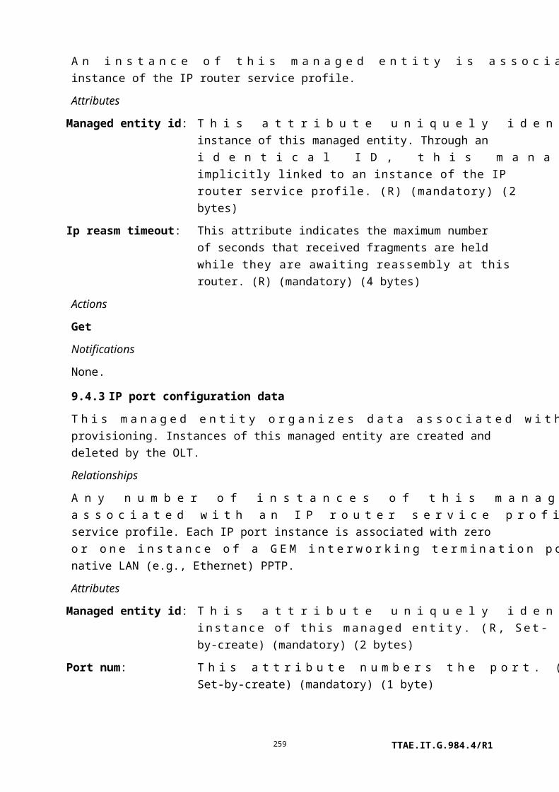
dot11 RTS failure count: This attribute counts failures to receive CTS in response to an RTS. (R) (mandatory) (4 bytes)
dot11 ACK failure count: This attribute counts failures to receive ACK when expected. (R) (mandatory) (4 bytes)
dot11 received fragment count:
This attribute counts successfully received MPDUs of type data or management. (R) (mandatory) (4 bytes)
dot11 multicast received frame count:
This attribute counts received MSDUs whose multicast bit is set in the destination MAC address. (R) (mandatory) (4 bytes)
dot11 FCS error count: This attribute counts FCS errors detected in received MPDUs. (R) (mandatory) (4 bytes)
dot11 transmitted frame count:
This attribute counts successfully transmitted MSDUs. (R) (mandatory) (4 bytes)
dot11 WEP undecryptable count:
This attribute counts frames received whose frame control field, WEP subfield, is 1, when the WEPOn value for the key mapped to the TA's MAC address indicates that the frame should not have been encrypted. It also counts frames discarded because the receiving STA did not implement the privacy option. (R) (mandatory) (4 bytes)
Actions
Create, delete, get, set
Get current data (optional)
Notifications
Threshold crossing alert
Number Threshold crossing alert Threshold value attribute # (Note)
0 dot11 failed 1
1 dot11 RTS failure 2
2 dot11 ACK failure 3
3 dot11 FCS error 4
4 dot11 WEP undecryptable 5
NOTE – This number associates the TCA with the specified threshold value attribute of the
threshold data 1 managed entity.
TTAE.IT.G.984.4/R1259

9.7 xDSL services
This clause defines managed entities associated with physical xDSL UNIs, as shown in Figure 9.7-1.
Figure 9.7-1 – Managed entities associated with physical xDSL UNIs
9.7.1 Physical path termination point xDSL UNI part 1
This managed entity represents the point where physical paths terminate on an xDSL CO modem (xTU-C). The xDSL managed entity family is used for ADSL and VDSL2 services (an existing legacy family of VDSL managed entities remains valid for [ITU-T G.993.1] VDSL. It is documented in [ITU-T G.983.2]).
The ONT automatically creates an instance of this managed entity per port:
• When the ONT has xDSL ports built into its factory configuration.
• When a cardholder is provisioned to expect a circuit pack of xDSL type.
• When a cardholder provisioned for plug-and-play is equipped with a circuit pack of xDSL type. Note that the installation of a plug-and-play card may indicate the presence of xDSL ports via equipment ID as well as its type, and indeed may cause the ONT to instantiate a port mapping package that specifies xDSL ports.
The ONT automatically deletes instances of this managed entity when a cardholder is neither provisioned to expect an xDSL circuit pack, nor is it equipped with an xDSL circuit pack.
TTAE.IT.G.984.4/R1260

Relationships
An instance of this managed entity is associated with each instance of a real or preprovisioned xDSL port.
Attributes
Managed entity id: This attribute uniquely identifies each instance of this managed entity. This two-byte number indicates the physical position of the UNI. The six least significant bits of the first byte are the slot id, defined in clause 9.1.5. The two most significant bits indicate the channel number in some of the implicitly linked MEs, and must be 0 in the PPTP itself. This reduces the possible number of physical slots to 64. The second byte is the port ID, with range 1..255. (R) (mandatory) (2 bytes)
Loopback configuration: This attribute represents the loopback configuration of this physical interface.
0 No loopback.1 Loopback2 – A loopback at the ONT toward the OLT.
The OLT can execute a physical level loopback test after loopback2 is set.
Upon ME instantiation, the ONT sets this attribute to 0. (R, W) (mandatory) (1 byte)
Administrative state: This attribute locks (1) and unlocks (0) the functions performed by this managed entity. When the administrative state is set to lock, all user functions of this UNI are blocked, and alarms, TCAs and AVCs for this managed entity and all dependent managed entities are no longer generated. Selection of a default value for this attribute is outside the scope of this Recommendation. (R, W) (mandatory) (1 byte)
Operational state: This attribute indicates whether or not the managed entity is capable of performing its function. Valid values are enabled (0) and disabled (1). (R) (optional) (1 byte)
TTAE.IT.G.984.4/R1261

xDSL line configuration profile:
This attribute points to an instance of the xDSL line configuration profiles (part 1, 2 and 3) managed entities, and if [ITU-T G.993.2] VDSL2 is supported, also to a VDSL2 line configuration extensions ME. Upon ME instantiation, the ONT sets this attribute to 0, a null pointer. (R, W) (mandatory) (2 bytes)
xDSL subcarrier masking downstream profile:
This attribute points to an instance of the xDSL subcarrier masking downstream profile managed entity. Upon ME instantiation, the ONT sets this attribute to 0, a null pointer. (R, W) (mandatory) (2 bytes)
xDSL subcarrier masking upstream profile:
This attribute points to an instance of the xDSL subcarrier masking upstream profile managed entity. Upon ME instantiation, the ONT sets this attribute to 0, a null pointer. (R, W) (mandatory) (2 bytes)
xDSL downstream PSD mask profile:
This attribute points to an instance of the xDSL PSD mask profile managed entity that defines downstream parameters. Upon ME instantiation, the ONT sets this attribute to 0, a null pointer. (R, W) (mandatory) (2 bytes)
xDSL downstream RFI bands profile:
This attribute points to an instance of the xDSL downstream RFI bands profile managed entity. Upon ME instantiation, the ONT sets this attribute to 0, a null pointer. (R, W) (mandatory) (2 bytes)
ARC: See clause I.1.8. (R, W) (optional) (1 byte)
ARC interval: See clause I.1.8. (R, W) (optional) (1 byte)
Modem type: This attribute specifies the modem type. If the hardware cannot support the requested modem type, the ONT should deny the provisioning command. For backward compatibility, the attribute is optional, with a default of ATM.
0 Undefined.1 ATM (default).2 PTM (Ethernet).
(R, W) (optional) (1 byte)
Upstream PSD mask profile: This attribute points to an instance of the xDSL PSD mask profile that defines upstream parameters. Upon ME instantiation, the ONT sets this attribute to 0, a null pointer. (R, W) (optional) (2 bytes)
TTAE.IT.G.984.4/R1262

Actions
Get, set
Notifications
Attribute value change
Number Attribute value change Description
1..2 N/A
3 Op state Operational state
4..8 N/A
9 ARC ARC timer expiration
10..13 N/A
14..16 Reserved
Alarm
Number Alarm Description
0 NE LOF Near end loss of frame
1 NE LOS Near end loss of signal
2 NE LOL Near end loss of link
3 NE LPR Near end loss of power
4 Card alm Card in alarm
5 FE LOF Far end loss of frame
6 FE LOS Far end loss of signal
7 FE LOL Far end loss of link
8 FE LPR Far end loss of power
9 DRT up Data rate threshold upshift (Note 1)
10 DRT down Data rate threshold downshift (Note 1)
11 LINIT Line initialization failure
12 LCD Loss of cell delineation, near end (Note 2)
13 NCD No cell delineation, near end (Note 2)
14 LCD-FE Loss of cell delineation, far end (Note 2)
15 NCD-FE No cell delineation, far end (Note 2)
16..207 Reserved
208..223 Vendor-specific alarms Not to be standardized
TTAE.IT.G.984.4/R1263

Alarm
Number Alarm Description
NOTE 1 – The data rate upshift and downshift alarms are deprecated. They are not defined in
[ITU-T G.997.1].
NOTE 2 – These alarms are meaningful only for ATM transport. The alarms may be declared
against the UNI itself, or against one of the bearer channels. In the latter case, the two MSBs of
the instance identifier in the alarm message specify the bearer channel.
9.7.2 Physical path termination point xDSL UNI part 2
This managed entity represents the point in the ONT where physical paths terminate on an xDSL CO modem (xTU-C). Standards and chip sets support several forms of DSL, including VDSL2, and the xDSL managed entity family is used for all of them, with specific extensions for technology variations (a legacy family of managed entities is documented in [ITU-T G.983.2] for [ITU-T G.993.1] VDSL1).
The ONT creates or deletes an instance of this managed entity at the same time it creates or deletes the corresponding PPTP xDSL UNI part 1.
Relationships
An instance of this managed entity is associated with each instance of a physical path termination point xDSL UNI part 1.
Attributes
Managed entity id: This attribute uniquely identifies each instance of this managed entity. Through an identical ID, this managed entity is implicitly linked to an instance of the physical path termination point xDSL UNI part 1. (R) (mandatory) (2 bytes)
Each of the following eight attributes is a pointer to an xDSL channel configuration profile managed entity. In each case, the default value 0, set when the ME is auto-created, is a null pointer.
xDSL channel configuration profile for bearer channel 0 downstream:
(R, W) (optional) (2 bytes)
xDSL channel configuration profile for bearer channel 1 downstream:
(R, W) (optional) (2 bytes)
xDSL channel configuration profile for bearer channel 2 downstream:
(R, W) (optional) (2 bytes)
TTAE.IT.G.984.4/R1264

xDSL channel configuration profile for bearer channel 3 downstream:
(R, W) (optional) (2 bytes)
xDSL channel configuration profile for bearer channel 0 upstream:
(R, W) (optional) (2 bytes)
xDSL channel configuration profile for bearer channel 1 upstream:
(R, W) (optional) (2 bytes)
xDSL channel configuration profile for bearer channel 2 upstream:
(R, W) (optional) (2 bytes)
xDSL channel configuration profile for bearer channel 3 upstream:
(R, W) (optional) (2 bytes)
Actions
Get, set
Notifications
None.
9.7.3 xDSL line configuration profile part 1
The overall xDSL line configuration profile is modelled in several parts, all of which are associated together through a common managed entity id (the client physical path termination point xDSL UNI part 1 has a single pointer, which refers to the entire set of line configuration profile parts).
Be aware that a number of attributes in the line configuration profile family affect the real-time service delivery of an xDSL UNI, for example by triggering diagnostics. Despite the fact that they are called profiles, it may be advisable to instantiate a complete set of these MEs for each PPTP xDSL UNI.
Relationships
An instance of this managed entity may be associated with zero or more instances of the physical path termination point xDSL UNI.
Attributes
Managed entity id: This attribute uniquely identifies each instance of this managed entity. The value 0 is reserved. All xDSL and VDSL2 line configuration profiles that pertain to a given physical path termination point xDSL must share a common managed entity id. (R, Set-by-create) (mandatory) (2 bytes)
xTU transmission system enabling
This configuration attribute specifies the transmission system coding types to be allowed by the near-end xTU. It is a bit map as
TTAE.IT.G.984.4/R1265

(xTSE): defined in Table 9.7.12-1.
NOTE 1 – An additional byte enabling VDSL2 capabilities is defined in the VDSL2 transmission system enabling attribute of the xDSL line configuration profile part 2 managed entity.
(R, W, Set-by-create) (mandatory) (7 bytes)
TTAE.IT.G.984.4/R1266

Power management state forced:
This configuration parameter forces the line state of the near-end xTU. It is coded as an integer value with following definition:0 Force the line from the L3 idle state to the L0 full-on state.
This transition requires the short initialization procedures. After reaching the L0 state, the line may enter into or exit from the L2 low power state if the L2 state is enabled. If the L0 state is not reached after a vendor-discretionary number of retries and/or within a vendor-discretionary timeout, an initialization failure occurs. Whenever the line is in the L3 state, it attempts to transition to the L0 state until it is forced into another state through this configuration parameter.
2 Force the line from the L0 full-on to L2 low power state. This is an out-of-service test value for triggering the L2 mode.
3 Force the line from the L0 full-on or L2 low power state to the L3 idle state. This transition requires the orderly shutdown procedure. After reaching the L3 state, the line remains there until it is forced into another state through this configuration parameter.
(R, W, Set-by-create) (mandatory) (1 byte)
Power management state enabling:
This configuration parameter specifies the line states into which the xTU-C or xTU-R may autonomously go. It is a bit map (0 if not allowed, 1 if allowed) with the following definition:
Bit 1 (LSB): L3 idle state.Bit 2: L1/L2 low power state.
(R, W, Set-by-create) (mandatory) (1 byte)
Downstream target noise margin:
This attribute specifies the noise margin the xTU-R receiver must achieve, relative to the BER requirement for each of the downstream bearer channels, to successfully complete initialization. Its value ranges from 0 (0.0 dB) to 310 (31.0 dB). (R, W, Set-by-create) (mandatory) (2 bytes)
Upstream target noise margin:
This attribute specifies the noise margin the xTU-C receiver must achieve, relative to the BER requirement for each of the upstream bearer channels, to successfully complete initialization. Its value ranges from 0 (0.0 dB) to 310 (31.0 dB). (R, W, Set-by-create) (mandatory) (2 bytes)
Downstream maximum noise
The MAXSNRMds attribute specifies the maximum noise margin the xTU-R receiver tries to sustain. If the noise margin is above
TTAE.IT.G.984.4/R1267

margin: this level, the xTU-R requests the xTU-C to reduce its transmit power, if this functionality is supported by the pertinent xDSL Recommendation. Its value ranges from 0 (0.0 dB) to 310 (31.0 dB). The special value 0xFFFF indicates that the maximum noise margin limit is unbounded. (R, W, Set-by-create) (mandatory) (2 bytes)
Upstream maximum noise margin:
The MAXSNRMus attribute specifies the maximum noise margin the xTU-C receiver tries to sustain. If the noise margin is above this level, the xTU-C requests the xTU-R to reduce its transmit power, if this functionality is supported by the pertinent xDSL Recommendation. Its value ranges from 0 (0.0 dB) to 310 (31.0 dB). The special value 0xFFFF indicates that the maximum noise margin limit is unbounded. (R, W, Set-by-create) (mandatory) (2 bytes)
Downstream minimum noise margin:
This attribute specifies the minimum noise margin the xTU-R receiver must tolerate. If the noise margin falls below this level, the xTU-R requests the xTU-C to increase its transmit power. If an increase in xTU-C transmit power is not possible, a loss-of-margin (LOM) defect occurs, the xTU-R fails and attempts to re-initialize, and the PPTP declares a line initialization failure (LINIT) alarm. Its value ranges from 0 (0.0 dB) to 310 (31.0 dB). (R, W, Set-by-create) (mandatory) (2 bytes)
Upstream minimum noise margin:
This attribute specifies the minimum noise margin the xTU-C receiver must tolerate. If the noise margin falls below this level, the xTU-C requests the xTU-R to increase its transmit power. If an increase in xTU-R transmit power is not possible, a loss-of-margin (LOM) defect occurs, the xTU-C fails and attempts to re-initialize, and the PPTP declares a line initialization failure (LINIT) alarm. Its value ranges from 0 (0.0 dB) to 310 (31.0 dB). (R, W, Set-by-create) (mandatory) (2 bytes)
Downstream rate adaptation mode:
The RA-MODEds attribute specifies the mode of operation of a rate-adaptive xTU-C in the transmit direction. The parameter can take four values.
1 Mode 1: MANUAL – Rate changed manually.
At startup:
The downstream minimum data rate parameter (see xDSL channel config profile) specifies the
TTAE.IT.G.984.4/R1268

minimum required data rate for each downstream bearer channel, with a downstream noise margin that is at least as large as the specified downstream target noise margin, relative to the required BER for each of the downstream bearer channels. If the xTU-C fails to achieve the downstream minimum data rate for any of the bearer channels, the xTU-C fails to initialize and the PPTP declares a line initialization failure (LINIT) alarm. Although the xTU-C and the line might be able to support a higher data rate, the xTU-C does not transmit a higher data rate than is requested.
At showtime:
The xTU-C transmitter maintains the specified downstream minimum data rate for each of the bearer channels.
2 Mode 2: AT_INIT – Rate automatically selected at startup only; rate does not change after that.
TTAE.IT.G.984.4/R1269

At startup:
The downstream minimum rate parameter specifies the minimum required data rate for each downstream bearer channel, with a downstream noise margin that is at least as large as the specified downstream target noise margin, relative to the required BER for each of the bearer channels. If the xTU-C fails to achieve the downstream minimum data rate for any of the bearer channels, the xTU-C fails to initialize and the PPTP declares a line initialization failure (LINIT) alarm. If the xTU-C transmitter is able to support a higher downstream data rate at initialization, the excess data rate is distributed among the downstream bearer channels according to the weight specified by the rate adaptation ratio parameter of each bearer channel. When the downstream maximum data rate is achieved in one of the bearer channels, the remaining excess rate is assigned to the other bearer channels, still according to their relative rate adaptation ratio parameters. As long as the downstream data rate is below the downstream maximum data rate for one of the bearer channels, data rate increase takes priority over transmit power reduction.
At showtime:
During showtime, no downstream data rate adaptation is allowed. The downstream data rate, determined during initialization for each bearer channel, is maintained.
3 Mode 3: DYNAMIC – Data rate is automatically selected at initialization and is continuously adapted during showtime. The dynamic rate adaptation mode is optional. All related configuration parameters are also optional.
At startup:
The xTU-C starts up as in mode 2.
TTAE.IT.G.984.4/R1270

At showtime:
During showtime, rate adaptation is allowed according to the rate adaptation ratios for distributing the excess data rate amongst the bearer channels, as described in mode 2. The downstream data rate can vary between the downstream minimum data rate and the downstream maximum data rate. Downstream rate adaptation is performed when the conditions specified for downstream upshift noise margin and downstream upshift interval – or for downstream downshift noise margin and downstream downshift interval – are satisfied. This means:
• An upshift action is allowed when the downstream noise margin is above the downstream upshift noise margin during the downstream minimum time interval for upshift rate adaptation (i.e., upon RAU anomaly).
• A downshift action is allowed when the downstream noise margin is below the downstream downshift noise margin during the downstream minimum time interval for downshift rate adaptation (i.e., upon RAD anomaly).
As long as the downstream data rate is below the downstream maximum data rate for one of the bearer channels, data rate increase takes priority over transmit power reduction.
In G.993.2 startup, if it is detected that SRA is supported in the downstream direction by neither xTU, the xTUs fall back to mode 2.
4 Mode 4: DYNAMIC with SOS – Data rate is automatically selected at initialization and is continuously adapted during showtime by SOS and SRA. Rate adaptation mode 4 is optional, but if it is selected,
TTAE.IT.G.984.4/R1271
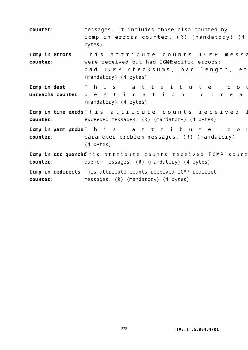
enabling of SOS and SRA is mandatory. This mode is defined only in [ITU-T G.993.2].
At startup:
The xTU-C starts up as in mode 2.
At showtime:
SRA behaviour is the same as described for mode 3, unless the actual net data rate is below the minimum net data rate as a result of an SOS procedure.
Additionally, SOS may be performed when the conditions specified by the SOS trigger parameters are satisfied. The detailed specification of the SOS OLR procedure appears in [ITU-T G.993.2].
If at startup, it is detected that SOS is supported in the downstream direction by neither xTU, but SRA is supported by both xTUs, the xTUs fall back to mode 3.
If at startup, it is detected that neither SOS nor SRA are supported in the downstream direction by both xTUs, the xTUs fall back to mode 2.
(R, W, Set-by-create) (mandatory) (1 byte)
Upstream rate adaptation mode:
The RA-MODEus attribute specifies the mode of operation of a rate-adaptive xTU-R in the transmit direction. The parameter is used only if rate-adaptive functionality is supported. It can take four values:
1 MANUAL2 AT_INIT3 DYNAMIC4 DYNAMIC with SOS
The definition of each of the values is identical to its definition in the downstream rate adaptation mode (replacing xTU-C with xTU-R and downstream with upstream). (R, W, Set-by-create) (mandatory) (1 byte)
Downstream upshift noise margin:
If the downstream noise margin is above the downstream upshift noise margin and remains there for more than the time specified by the downstream minimum upshift rate adaptation interval, the xTU-R attempts to increase the
TTAE.IT.G.984.4/R1272

downstream net data rate. This attribute ranges from 0 (0.0 dB) to 310 (31.0 dB). (R, W, Set-by-create) (optional) (2 bytes)
Upstream upshift noise margin:
If the upstream noise margin is above the upstream upshift noise margin and remains there for more than the time specified by the upstream minimum upshift rate adaptation interval, the xTU-C attempts to increase the upstream net data rate. This attribute ranges from 0 (0.0 dB) to 310 (31.0 dB). (R, W, Set-by-create) (optional) (2 bytes)
Upstream PSD mask selection: This attribute enables one of several upstream PSD masks. It is used only for Annexes J and M of [ITU-T G.992.3] and [ITU-T G.992.5]. The same mask selection applies to all relevant modes enabled in the xTSE line configuration parameter (Table 9.7.12-1). This attribute selects the mask with the following definition:
TTAE.IT.G.984.4/R1273

Annex J of G.992.3/5 Annex M of G.992.3/5
1 ADLU-32 EU-322 ADLU-36 EU-363 ADLU-40 EU-404 ADLU-44 EU-445 ADLU-48 EU-486 ADLU-52 EU-527 ADLU-56 EU-568 ADLU-60 EU-609 ADLU-64 EU-64
(R, W, Set-by-create) (mandatory) (1 byte)
Minimum overhead rate upstream:
This attribute specifies the minimum rate of the message based overhead to be maintained by the xTU in the upstream direction. MSGMINus ranges from 4000 to 248 000 bit/s. This attribute is only valid for [ITU-T G.992.3], [ITU-T G.992.4], [ITU-T G.992.5] and [ITU-T G.993.2].
NOTE 2 – For compatibility with previous versions, values between 4000 and 65535 are interpreted as bits per second. To align with [ITU-T G.997.1], values between 4 and 248 are interpreted as kilobits per second. For maximum flexibility, the ONT should support both conventions.
(R, W, Set-by-create) (optional) (2 bytes)
Minimum overhead rate downstream:
This attribute specifies the minimum rate of the message based overhead to be maintained by the xTU in the downstream direction. MSGMINds ranges from 4000 to 248 000 bit/s. This attribute is only valid for [ITU-T G.992.3], [ITU-T G.992.4], [ITU-T G.992.5] and [ITU-T G.993.2].
NOTE 3 – For compatibility with previous versions, values between 4000 and 65535 are interpreted as bits per second. To align with [ITU-T G.997.1], values between 4 and 248 are interpreted as kilobits per second. For maximum flexibility, the ONT should support both conventions.
(R, W, Set-by-create) (optional) (2 bytes)
TTAE.IT.G.984.4/R1274
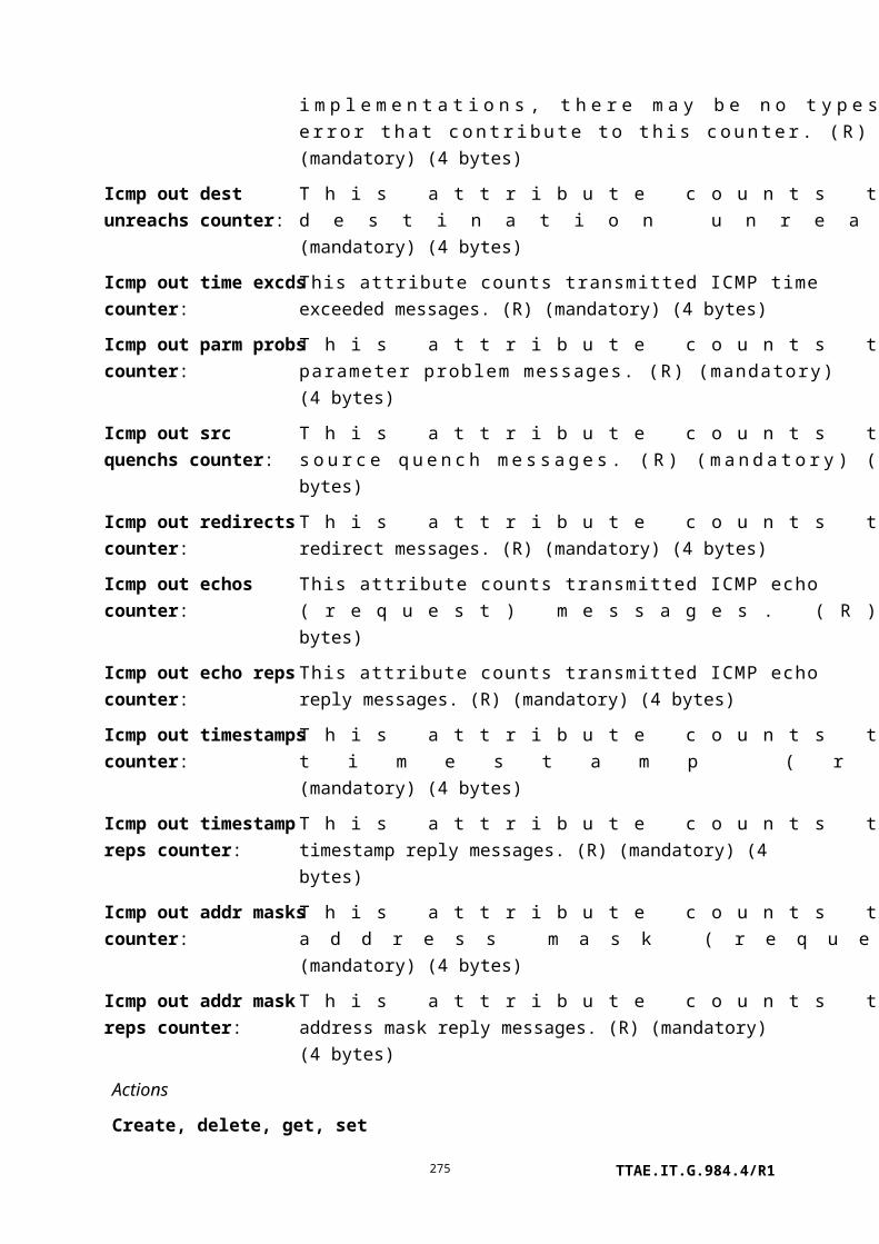
Actions
Create, delete, get, set
Notifications
None.
9.7.4 xDSL line configuration profile part 2
The overall xDSL line configuration profile is modelled in several parts, all of which are associated together through a common managed entity id (the client physical path termination point xDSL UNI part 1 has a single pointer, which refers to the entire set of line configuration profile parts).
Relationships
An instance of this managed entity may be associated with zero or more instances of the physical path termination point xDSL UNI part 1.
Attributes
TTAE.IT.G.984.4/R1275

Managed entity id: This attribute uniquely identifies each instance of this managed entity. All xDSL and VDSL2 line configuration profiles that pertain to a given physical path termination point xDSL must share a common managed entity id. (R, Set-by-create) (mandatory) (2 bytes)
Downstream minimum time interval for upshift rate adaptation:
This parameter defines the interval during which the downstream noise margin must remain above the downstream upshift noise margin before the xTU-R attempts to increase the downstream net data rate. Its value ranges from 0 to 16383 seconds. (R, W, Set-by-create) (optional) (2 bytes)
Upstream minimum time interval for upshift rate adaptation:
This parameter defines the interval during which the upstream noise margin must remain above the upstream upshift noise margin before the xTU-C attempts to increase the upstream net data rate. Its value ranges from 0 to 16383 seconds. (R, W, Set-by-create) (optional) (2 bytes)
Downstream downshift noise margin:
If the downstream noise margin is below the downstream downshift noise margin and remains there for more than the downstream minimum downshift rate adaptation interval, the xTU-R attempts to decrease the downstream net data rate. This attribute's value ranges from 0 (0.0 dB) to 310 (31.0 dB). (R, W, Set-by-create) (optional) (2 bytes)
Upstream downshift noise margin:
If the upstream noise margin is below the upstream downshift noise margin and remains there for more than the upstream minimum downshift rate adaptation interval, the xTU-C attempts to decrease the upstream net data rate. This attribute's value ranges from 0 (0.0 dB) to 310 (31.0 dB). (R, W, Set-by-create) (optional) (2 bytes)
Downstream minimum time interval for downshift rate adaptation:
This parameter defines the interval during which the downstream noise margin must remain below the downstream downshift noise margin before the xTU-R attempts to decrease the downstream net data rate. Its value ranges from 0 to 16383 seconds. (R, W, Set-by-create) (optional) (2 bytes)
TTAE.IT.G.984.4/R1276

Upstream minimum time interval for downshift rate adaptation:
This parameter defines the interval during which the upstream noise margin must remain below the upstream downshift noise margin before the xTU-C attempts to decrease the upstream net data rate. Its value ranges from 0 to 16383 seconds. (R, W, Set-by-create) (optional) (2 bytes)
xTU impedance state forced: This parameter forces the impedance state of the xTU-C. It applies only to the T/S interface, and is deprecated in OMCI, which stands proxy for the Q interface. It is only valid for Annex A of [ITU-T G.992.3], Annex A of [ITU-T G.992.4] and Annex A of [ITU-T G.992.5]. It is defined as follows:
1 Force the xTU-C to the disabled state.2 Force the xTU-C to the inactive state.3 Force the xTU-C to the active state.
(R, W, Set-by-create) (optional) (1 byte)
TTAE.IT.G.984.4/R1277

L0-time: This parameter specifies the minimum time between an exit from the L2 state and the next entry into the L2 state. It is only valid for [ITU-T G.992.3], [ITU-T G.992.4] and [ITU-T G.992.5]. It ranges from 0 to 255 seconds. (R, W, Set-by-create) (mandatory) (1 byte)
L2-time: This parameter specifies the minimum time between an entry into the L2 state and the first power trim in the L2 state, or between two consecutive power trims in the L2 state. It is only valid for [ITU-T G.992.3], [ITU-T G.992.4] and [ITU-T G.992.5]. It ranges from 0 to 255 seconds. (R, W, Set-by-create) (mandatory) (1 byte)
Downstream maximum nominal power spectral density:
This attribute specifies the maximum nominal transmit PSD in the downstream direction during initialization and showtime. A single MAXNOMPSDds attribute is defined per mode enabled in the xTSE line configuration attribute. It is only valid for [ITU-T G.992.3], [ITU-T G.992.4] and [ITU-T G.992.5]. Its value ranges from 0 (–60.0 dBm/Hz) to 300 (–30 dBm/Hz). (R, W, Set-by-create) (mandatory) (2 bytes)
Upstream maximum nominal power spectral density:
This attribute specifies the maximum nominal transmit PSD in the upstream direction during initialization and showtime. A single MAXNOMPSDus attribute is defined per mode enabled in the xTSE line configuration attribute. It is only valid for [ITU-T G.992.3], [ITU-T G.992.4] and [ITU-T G.993.2]. Its value ranges from 0 (–60.0 dBm/Hz) to 300 (–30 dBm/Hz). (R, W, Set-by-create) (mandatory) (2 bytes)
Downstream maximum nominal aggregate transmit power:
This attribute specifies the maximum nominal aggregate transmit power in the downstream direction during initialization and showtime. It is only valid for [ITU-T G.992.3], [ITU-T G.992.4], [ITU-T G.992.5] and [ITU-T G.993.2]. Its value ranges from 0 (0.0 dBm) to 255 (25.5 dBm). (R, W, Set-by-create) (mandatory) (1 byte)
Upstream maximum nominal aggregate transmit power:
This parameter specifies the maximum nominal aggregate transmit power in the upstream direction during initialization and showtime. It is only valid for [ITU-T G.992.3], [ITU-T G.992.4] and [ITU-T G.992.5]. Its value ranges from 0 (0.0 dBm) to 255 (25.5 dBm). (R,
TTAE.IT.G.984.4/R1278

W, Set-by-create) (mandatory) (1 byte)
Upstream maximum aggregate receive power:
This parameter specifies the maximum upstream aggregate receive power over a set of subcarriers, as defined in the relevant Recommendation. The xTU-C requests an upstream power cutback such that the upstream aggregate receive power over that set of subcarriers is at or below the configured maximum value. It is only valid for [ITU-T G.992.3], [ITU-T G.992.4] and [ITU-T G.992.5]. This attribute ranges from 0 (–25.5 dBm) to 510 (+25.5 dBm). The special value 0xFFFF indicates that no upstream maximum aggregate receive power limit is to be applied. (R, W Set-by-create) (mandatory) (2 bytes)
VDSL2 transmission system enabling:
This configuration attribute extends the transmission system coding types to be allowed by the xTU-C. It is a bit map, defined as octet 8 (bits 57..64) in Table 9.7.12-1. (R, W, Set-by-create) (optional) (1 byte)
Actions
Create, delete, get, set
Notifications
None.
9.7.5 xDSL line configuration profile part 3
The overall xDSL line configuration profile is modelled in several parts, all of which are associated together through a common managed entity id (the client physical path termination point xDSL UNI part 1 has a single pointer, which refers to the entire set of line configuration profile parts).
Relationships
An instance of this managed entity may be associated with zero or more instances of the physical path termination point xDSL UNI part 1.
Attributes
TTAE.IT.G.984.4/R1279

Managed entity id: This attribute uniquely identifies each instance of this managed entity. All xDSL and VDSL2 line configuration profiles that pertain to a given physical path termination point xDSL must share a common managed entity id. (R, Set-by-create) (mandatory) (2 bytes)
Loop diagnostics mode forced (LDSF):
This configuration parameter forces the line into loop diagnostic mode via the xTU-C. It is only valid for [ITU-T G.992.3], [ITU-T G.992.4] and [ITU-T G.992.5]. It is defined as follows:
0 Inhibits the xTU-C from performing loop diagnostic mode procedures on the line. Loop diagnostic mode procedures may still be initiated by the xTU-R.
1 Forces the xTU-C to perform the loop diagnostics procedures.
Only while the line power management state is L3 can the line be forced into loop diagnostic mode. When loop diagnostic procedures complete successfully, the ONT resets this attribute to 0. The line remains in L3 idle state. The loop diagnostics data are available at least until the line is forced to the L0 state. As long as loop diagnostic procedures have not completed successfully, attempts are made to do so, until the loop diagnostic mode is no longer forced on the line through this configuration parameter. If loop diagnostic procedures cannot be completed successfully after a vendor-discretionary number of retries and/or within a vendor-discretionary timeout, then an initialization failure occurs. (R, W, Set-by-create) (mandatory) (1 byte)
Automode cold start forced: This attribute is defined to improve testing of the performance of xTUs supporting automode. Valid values are 0 and 1. A change in value of this attribute indicates a change in loop conditions applied to the devices under test. The xTUs reset any historical information used for automode, for shortening G.994.1 handshake, or for shortening the initialization procedure.
TTAE.IT.G.984.4/R1280

Automode is defined as the case where multiple operation modes are enabled in xTSE Table 9.7.12-1 and where the selection of the operation mode to be used for transmission depends, not only on the common capabilities of both xTUs (as exchanged in [ITU-T G.994.1]), but also on achievable data rates under given loop conditions. (R, W, Set-by-create) (mandatory if automode supported) (1 byte)
L2-ATPR: This parameter specifies the maximum aggregate transmit power reduction that can be performed in the L2 request (i.e., at the transition of L0 to L2 state) or through a single power trim in the L2 state. It is only valid for [ITU-T G.992.3], [ITU-T G.992.4] and [ITU-T G.992.5]. This attribute ranges from 0 (0 dB) dB to 31 (31 dB). (R, W, Set-by-create) (mandatory) (1 byte)
L2-ATPRT: This parameter specifies the total maximum aggregate transmit power reduction (in dB) that can be performed in an L2 state. This is the sum of all reductions of L2 requests (i.e., at transitions from L0 to L2 state) and power trims. This attribute ranges from 0 (0 dB) dB to 31 (31 dB). (R, W, Set-by-create) (mandatory) (1 byte)
Force INP downstream: When set to 1, the FORCEINPds attribute forces the framer settings of all downstream bearer channels to be selected such that the impulse noise protection computed according to the formula specified in the relevant Recommendation is greater than or equal to the minimal impulse noise protection requirement. The default value 0 disables this function. (R, W) (mandatory for [ITU-T G.993.2], optional for other Recommendations that support it) (1 byte)
Force INP upstream: When set to 1, the FORCEINPus attribute forces the framer settings of all upstream bearer channels to be selected such that the impulse noise protection computed according to the formula specified in the relevant Recommendation is greater than or equal to the minimal impulse noise protection requirement. The default value 0 disables this function. (R, W) (mandatory for [ITU-T G.993.2], optional for other Recommendations that support it) (1 byte)
TTAE.IT.G.984.4/R1281

Update request flag for near-end test parameters:
The UPDATE-TEST-NE attribute forces an update of all near-end test parameters that can be updated during showtime in [ITU-T G.993.2]. Update is triggered by setting this attribute to 1, whereupon the near-end test parameters are expected to be updated within 10 seconds, and the ONT should reset the attribute value to 0. The update request flag is independent of any autonomous update process in the system. The update request attribute must be prepared to accept another set after a period not to exceed 3 minutes, a period that starts when the flag is set via OMCI or by an autonomous process in the system. (R, W) (optional) (1 byte)
Update request flag forfar-end test parameters:
The UPDATE-TEST-FE attribute forces an update of all far-end test parameters that can be updated during showtime in [ITU-T G.993.2]. Update is triggered by setting this attribute to 1, whereupon the far-end test parameters are expected to be updated within 10 seconds, and the ONT should reset the attribute value to 0. The update request flag is independent of any autonomous update process in the system. The update request attribute must be prepared to accept another set after a period not to exceed 3 minutes, a period that starts when the flag is set via OMCI or by an autonomous process in the system. (R, W) (optional) (1 byte)
The following eight attributes configure the impulse noise monitoring function, whose results are available via the xDSL impulse noise monitor performance monitoring history data managed entity.
TTAE.IT.G.984.4/R1282

INM inter-arrival time offset upstream:
INMIATOus is the inter-arrival time offset that the xTU-C receiver uses to determine in which bin of the inter-arrival time histogram the IAT is reported. Valid values for INMIATO range from 3 to 511 DMT symbols in steps of 1 DMT symbol. (R, W) (optional) (2 bytes)
INM inter-arrival time step upstream:
INMIATSus is the inter-arrival time step that the xTU-C receiver uses to determine in which bin of the inter-arrival time histogram the IAT is reported. Valid values for INMIATS range from 0 to 7 in steps of 1. (R, W) (optional) (1 byte)
INM cluster continuation value upstream:
INMCCus is the cluster continuation value that the xTU-C receiver uses in the cluster indication process described in the pertinent Recommendation. Valid values for INMCC range from 0 to 64 DMT symbols in steps of 1 DMT symbol. (R, W) (optional) (1 byte)
INM equivalent INP mode upstream:
INM_INPEQ_MODEus is the INM equivalent INP mode that the xTU-C receiver uses in the computation of the equivalent INP, as defined in the pertinent Recommendation. Valid values for INM_INPEQ_MODE are 0..4. (R, W) (optional) (1 byte)
INM inter-arrival time offset downstream:
INMIATOds is the inter-arrival time offset that the xTU-R receiver uses to determine in which bin of the inter-arrival time histogram the IAT is reported. Valid values for INMIATO range from 3 to 511 DMT symbols in steps of 1 DMT symbol. (R, W) (optional) (2 bytes)
INM inter-arrival time step downstream:
INMIATSds is the inter-arrival time step that the xTU-R receiver uses to determine in which bin of the inter-arrival time histogram the IAT is reported. Valid values for INMIATS range from 0 to 7 in steps of 1. (R, W) (optional) (1 byte)
INM cluster continuation value downstream:
INMCCds is the cluster continuation value that the xTU-R receiver uses in the cluster indication process described in the pertinent Recommendation. Valid values for INMCC range from 0 to 64 DMT symbols in steps of 1 DMT symbol. (R, W) (optional) (1 byte)
INM equivalent INP mode downstream:
INM_INPEQ_MODEds is the INM equivalent INP mode that the xTU-R receiver uses in the computation of the
TTAE.IT.G.984.4/R1283
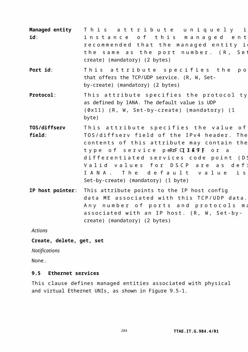
equivalent INP, as defined in the pertinent Recommendation. Valid values for INM_INPEQ_MODE are 0..4. (R, W) (optional) (1 byte)
Actions
Create, delete, get, set
Notifications
Attribute value change
Number Attribute value change Description
1..6 N/A
7 Update request NE Need only be reported on the 1 to 0 transition to signal the
OLT that test parameters have been updated.
8 Update request FE Need only be reported on the 1 to 0 transition to signal the
OLT that test parameters have been updated.
9..16 Reserved
9.7.6 VDSL2 line configuration extensions
This managed entity extends the xDSL line configuration MEs with attributes that are unique to [ITU-T G.993.2] VDSL2. Due to continuing standards development, some attributes – and therefore this managed entity – have also become applicable to other Recommendations, specifically [ITU-T G.992.3] and [ITU-T G.992.5]. The attributes of this ME are further defined in [ITU-T G.997.1]. An instance of this managed entity is created and deleted by the OLT.
Relationships
An instance of this managed entity may be associated with zero or more instances of the physical path termination point xDSL UNI part 1.
The overall xDSL line configuration profile is modelled in several parts, all of which are associated together through a common managed entity id (the client physical path termination point xDSL UNI part 1 has a single pointer, which refers to the entire set of line configuration parts).
Attributes
TTAE.IT.G.984.4/R1284

Managed entity id: This attribute uniquely identifies each instance of this managed entity. All xDSL and VDSL2 line configuration profiles that pertain to a given physical path termination point xDSL must share a common managed entity id. (R, Set-by-create) (mandatory) (2 bytes)
VDSL2 profiles enabling:
This attribute (PROFILES) contains the G.993.2 profiles to be allowed by the xTU-C. It is coded in a bit map representation (0 if not allowed, 1 if allowed) with the following definition:
Bit Meaning
1 (LSB) G.993.2 profile 8a.2 G.993.2 profile 8b.3 G.993.2 profile 8c.4 G.993.2 profile 8d.5 G.993.2 profile 12a.6 G.993.2 profile 12b.7 G.993.2 profile 17a.8 G.993.2 profile 30a.
(R, W, Set-by-create) (mandatory) (1 byte)
VDSL2 PSD mask class selection (CLASSMASK):
To reduce the number of configuration possibilities, the limit PSD masks are grouped in the following PSD mask classes:
• Class 998 Annex A of [ITU-T G.993.2]: D-32, D-48, D-64, D-128
• Class 997-M1c Annex B of [ITU-T G.993.2]: 997-M1c-A-7• Class 997-M1x Annex B of [ITU-T G.993.2]: 997-M1x-M-8,
997-M1x-M• Class 997-M2x Annex B of [ITU-T G.993.2]: 997-M2x-M-8,
997-M2x-A, 997-M2x-M, 997E17-M2x-NUS0, 997E30-M2x-NUS0
• Class 998-M1x Annex B of [ITU-T G.993.2]: 998-M1x-A, 998-M1x-B, 998-M1x-NUS0
• Class 998-M2x Annex B of [ITU-T G.993.2]: 998-M2x-A, 998-M2x-M, 998-M2x-B, 998-M2x-NUS0, 998E17-M2x-NUS0, 998E17-M2x-NUS0-M, 998E30-M2x-NUS0, 998E30-M2x-NUS0-M
• Class 998ADE-M2x Annex B of [ITU-T G.993.2]: 998-M2x-A, 998-M2x-M, 998-M2x-B, 998-M2x-NUS0, 998ADE17-M2x-A, 998ADE17-M2x-B, 998ADE17-M2x-NUS0-M,
TTAE.IT.G.984.4/R1285

998ADE30-M2x-NUS0-A, 998ADE30-M2x-NUS0-M• Class 998-B Annex C: POTS-138b, POTS-276b
(clause C.2.1.1 of [ITU-T G.993.2]), TCM-ISDN (clause C.2.1.2 of [ITU-T G.993.2])
• Class 998-CO Annex C of [ITU-T G.993.2]: POTS-138co, POTS-276co (clause C.2.1.1 of [ITU-T G.993.2])
• Class HPE-M1 Annex B of [ITU-T G.993.2]: HPE17-M1-NUS0, HPE30-M1-NUS0
Each class is designed such that the PSD levels of each limit PSD mask of a specific class are equal in their respective passbands above 552 kHz.
The CLASSMASK attribute is defined per G.993.2 annex enabled in the xTSE table (see Table 9.7.12-1). It selects a single PSD mask class per G.993.2 annex to be activated at the VTU-O. The coding is as follows:
TTAE.IT.G.984.4/R1286

Attribute value G.993.2 Annex A G.993.2 Annex B G.993.2 Annex C
(etc.)
VDSL2 limit PSDmasks:
The LIMITMASK attribute contains the G.993.2 limit PSD masks of the selected PSD mask class, enabled by the near-end xTU for each class of profiles. One LIMITMASK parameter is defined per annex enabled in the xTSE (see Table 9.7.12-1).
The profiles are grouped in the following profile classes:
– Class 8: Profiles 8a, 8b, 8c, 8d.
– Class 12: Profiles 12a, 12b.
– Class 17: Profile 17a.
– Class 30: Profile 30a.
For each profile class, several limit PSD masks of the selected PSD mask class (CLASSMASK) may be enabled. The enabling attribute is coded in a bit map representation (0 if the associated mask is not allowed, 1 if it is allowed). The bit mask is defined in Table 9.7.6-1. (R, W, Set-by-create) (mandatory) (8 bytes)
VDSL2 US0 disabling: The US0DISABLE attribute specifies whether channel US0 is disabled for each limit PSD mask enabled in the LIMITMASK attribute.
For each limit PSD mask enabled in the LIMITMASK attribute, one bit indicates if US0 is disabled. The disabling attribute is a bit map where the value 1 specifies that US0 is disabled for the associated limit mask. The bit map has the same structure as the LIMITMASK attribute. (R, W, Set-by-create) (mandatory) (8 bytes)
VDSL2 US0 PSD masks:The US0MASK attribute contains the US0 PSD masks to be allowed by the xTU-C. This attribute is only defined for Annex A of [ITU-T G.993.2]. It is represented as a bit map (0 if not allowed, 1 if allowed) with the definitions of Table 9.7.6-2. (R, W, Set-by-create) (mandatory) (4 bytes)
VDSL2-CARMASK table:
This attribute specifies restrictions, additional to the band plan, that determine the set of subcarriers allowed for transmission in both upstream and downstream directions.
TTAE.IT.G.984.4/R1287
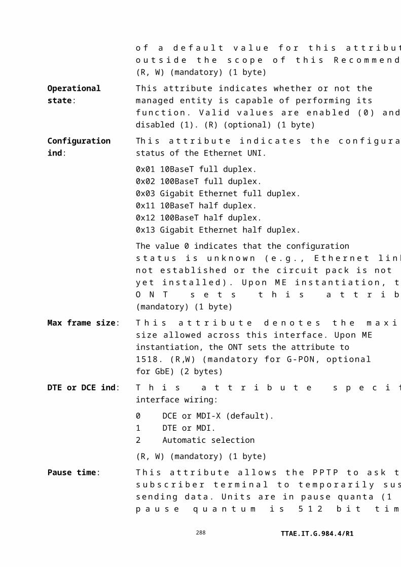
The VDSL2-CARMASK attribute describes the not-masked subcarriers in terms of one or more frequency bands. Each band is represented by start and stop subcarrier indices with a subcarrier spacing of 4.3125 kHz. The valid range of subcarrier indices is from 0 to at least the index of the highest allowed subcarrier in both transmission directions among all profiles enabled by the VDSL2 profiles enabling (PROFILES) attribute. Up to 32 bands may be specified. Other subcarriers are masked.
For profiles using 8.625 kHz tone spacing, the odd subcarrier indices i4.3125 in VDSL2-CARMASK can be transformed into actual subcarrier indices i8.625 using the following rule:
– For the start frequency of each band: i8.625 = (i4.3125 + 1)/2.
– For the stop frequency of each band: i8.625 = (i4.3125 – 1)/2.
The VDSL2-CARMASK attribute is a table where each entry comprises:
– An entry number field (1 byte, first entry numbered 1).
– Band start subcarrier index (2 bytes).
– Band stop subcarrier index (2 bytes).
By default, the table is empty. Entries are added or modified using the set action, which permits from one to as many as six breakpoints to be addressed in a single set message (Note 2). Setting a table entry with non-zero subcarrier references implies insertion into the table. Setting an entry's subcarrier references to zero implies deletion from the table, if present.
NOTE 2 – OMCI does not provide robust exception handling when more than one entry is included in a set command, and multiple values per set operation are not recommended.
The maximum number of breakpoints is 32, so the maximum size of the table is 160 bytes. (R, W) (mandatory) (5N bytes, where N is the number of bands)
CARMASK valid: This attribute controls and reports the status of the VDSL2-CARMASK table. If CARMASK valid = 1, then the VDSL2-CARMASK has been effectuated on the xDSL equipment. If CARMASK valid = 0 (default), then the VDSL2-CARMASK table is under construction and has not been effectuated on the xDSL equipment.
TTAE.IT.G.984.4/R1288

This attribute behaves as follows:
• If the OLT changes any of the VDSL2-CARMASK table entries or sets CARMASK valid = 0, then CARMASK valid = 0.
• If CARMASK valid = 0 and the OLT sets CARMASK valid = 1, then the ONT updates the xDSL equipment with the content of the table.
(R, W) (mandatory) (1 byte)
TTAE.IT.G.984.4/R1289

UPBOSHAPED: Upstream power back-off (UPBO) is specified in [ITU-T G.993.2] to provide spectral compatibility between loops of different lengths deployed in the same cable binder. The upstream transmit PSD mask, UPBOMASKus is defined in clause 7.2.1.3.2 of [ITU-T G.993.2].
The G.993.2 UPBO configuration attributes a and b are set by the OLT via this attribute. The reference length kl0_REF is set by the companion attribute UPBO klREF-pb, defined below. Further detail appears in [ITU-T G.997.1].
UPBOMASK (kl0 , f )=UPBOPSD( f )+LOSS (kl0 , f )+3.5 [dBm/Hz ]LOSS(kl0 , f )=kl0 √ f [ dB ]
where UPBOPSD(f) = –a-b√f.
The UPBO configuration attributes a and b are set by the OLT via this attribute. The value of kl0 may be determined during initialization by the VTUs or also set by the OLT. Further detail appears in [ITU-T G.997.1].
This attribute includes two parameters for each band. The parameters are a and b, in that order. Parameter a lies in the range 4000 (40.00 dBm/Hz) to 8095 (80.95 dBm/Hz). Parameter b lies in the range 0 (0.00 dBm/Hz) to 4095 (40.95 dBm/Hz). The special values a = b = 0 disable UPBO in the respective upstream band.
The upstream electrical length parameter UPBOKL defines the electrical length expressed in dB at 1 MHz, kl0, which may also be configured by the OLT. Its value ranges from 0 (0.0 dB) to 1280 (128.0 dB).
If the force electrical length parameter UPBOKLF is 1, the VTU-R is forced to use the electrical length from this attribute (UPBOKL) to compute UPBO. Otherwise, the VTUs determine the electrical length themselves.
TTAE.IT.G.984.4/R1290

Upstream band 1 a 2 bytes
b 2 bytes
Upstream band 2 a 2 bytes
b 2 bytes
Upstream band 3 a 2 bytes
b 2 bytes
Upstream band 4 a 2 bytes
b 2 bytes
Upstream band 5 a 2 bytes
b 2 bytes
UPBOKL 2 bytes
UPBOKLF 1 byte
(R, W) (mandatory) (23 bytes)
Cyclic extension: The CEFLAG attribute enables (1) the optional cyclic extension values. If set to 0, the cyclic extension is forced to the mandatory length 5N/32. (R, W) (mandatory) (1 byte)
Downstream SNR mode:The SNRMODEds attribute controls transmitter referred virtual noise in the downstream direction. If set to 1, virtual noise is disabled. If set to 2, virtual noise is enabled. (R, W) (mandatory) (1 byte)
Upstream SNR mode: The SNRMODEus attribute controls transmitter referred virtual noise in the upstream direction. If set to 1, virtual noise is disabled. If set to 2, virtual noise is enabled. (R, W) (mandatory) (1 byte)
Transmitter referred virtual noise downstream table:
The TXREFVNds table defines the downstream transmitter referred virtual noise. TXREFVNds is specified through a set of breakpoints. Each breakpoint comprises a subcarrier index t, with a subcarrier spacing of 4.3125 kHz, and a noise PSD level at that subcarrier. The set of breakpoints can then be represented as [(t1, PSD1), (t2, PSD2), … , (tN, PSDN)]. The subcarrier index t is an unsigned two-byte integer. The noise level is one byte whose value ranges from 0 (–40 dBm/Hz) to 200 (–140 dBm/Hz), in steps of 0.5 dB. Values between 201 and 254 indicate a noise PSD level of 0 W/Hz. The maximum number of breakpoints is 32; no more than 15 breakpoints may be configured below the upper edge of the passband of every mode enabled for [ITU-T G.992.3] and [ITU-T G.992.5].
TTAE.IT.G.984.4/R1291

Transmitter referred virtual noise upstream table:
The TXREFVNus attribute defines the upstream transmitter referred virtual noise. TXREFVNus is specified through a set of breakpoints. Each breakpoint comprises a subcarrier index t, with a subcarrier spacing of 4.3125 kHz, and a noise PSD level at that subcarrier. The set of breakpoints can then be represented as [(t1, PSD1), (t2, PSD2), … , (tN, PSDN)]. The subcarrier index t is an unsigned two-byte integer. The noise level is one byte whose value ranges from 0 (–40 dBm/Hz) to 200 (–140 dBm/Hz), in steps of 0.5 dB. Values between 201 and 254 indicate a noise PSD level of 0 W/Hz. The maximum number of breakpoints is 16; no more than 3 breakpoints may be configured below the upper edge of the passband of every mode enabled for [ITU-T G.992.3] and [ITU-T G.992.5].
DPBOSHAPED: Downstream power back-off – shaped as described in [ITU-T G.997.1] as a vector of parameters that modifies the downstream PSD mask.
DPBOEPSD – Assumed exchange PSD mask. This component points to an xDSL downstream PSD mask profile managed entity. It should contain not more than 16 break points. (2 bytes)
TTAE.IT.G.984.4/R1292

DPBOESEL – E-side electrical length. This component is the assumed loss at some reference frequency of the electrical cable from the xDSL equipment to a possible flexibility point. It ranges from 0 (0.0 dB) to 511 (255.5 dB) in steps of 0.5 dB. The value 0 has the special meaning that it disables the DPBOSHAPED feature. (2 bytes)
The following three parameters describe the cable model. Further detail appears in [ITU-T G.997.1]. Each is a scalar that represents the range –1 (coded as 0) to +1.5 (coded as 640) in steps of 1/256.
DPBOESCMA – (2 bytes)
DPBOESCMB – (2 bytes)
DPBOESCMC – (2 bytes)
DPBOMUS – Assumed minimum usable receive PSD mask. This component ranges from 0 (0.0 dBm/Hz) to 255 (–127.5 dBm/Hz) in steps of 0.5 dB. (1 byte)
DPBOFMIN – The lower frequency bound above which DPBO is applied. This component ranges from 0 (0.00 kHz) to 2048 (8832.00 kHz) in steps of 4.3125 kHz. (2 bytes)
DPBOFMAX – The upper frequency bound below which DPBO is applied. This component ranges from 32 (138.00 kHz) to 6956 (29997.75 kHz) in steps of 4.3125 kHz. (2 bytes)
(R, W) (optional) (15 bytes)
UPBOKLREF-pb: This attribute represents the reference loop length, the electrical length used to compute upstream power back-off for each upstream band except US0, for the optional equalized FEXT UPBO method. The value for each upstream band ranges from 1.8 to 63.5 dB in steps of 0.1 dB, i.e., with values 18..635. The special value 0 is also allowed, with semantics as defined in clause 7.2.1.3.2 of [ITU-T G.993.2]. (R, W) (optional) (2 bytes x 5 upstream bands)
Actions
Create, delete, get, get next, set, Set table (optional)
Notifications
None.
PSD mask classes:
TTAE.IT.G.984.4/R1293
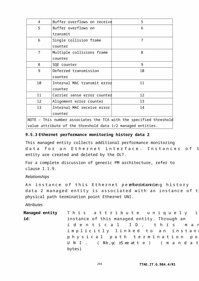
Table 9.7.6-1 – Limit mask definitions for each class mask
Annex A Annex B Annex C
Bit998
Annex A
998-M1x
Annex B
998-M2x
Annex B
998ADE-
M2x
Annex B
997-M1x
Annex B
997-M1c
Annex B
997-M2x
Annex B
HPE-M1
Annex B
998-B
Annex
C
998-CO
Annex C
Octet 1, profile class 8
1 D-32 M1x-A M2x-A M2x-A M1c-A-7 M2x-A POTS-
138b
POTS-
138co
2 D-48 M1x-B M2x-B M2x-B M1x-M-8 M2x-M-8 TCM-
ISDN
POTS-
276co
3 M2x-M M2x-M M1x-M M2x-M POTS-
276b
4 M1x-
NUS0
M2x-
NUS0
M2x-NUS0
5
6
7
8
Octet 2, profile class 8
1 D-64
2 D-128
3
4
5
6
7
8
Octet 3, profile class 12
1 D-32 M1x-A M2x-A M2x-A M2x-A POTS-
138b
POTS-
138co
2 D-48 M1x-B M2x-B M2x-B TCM-
ISDN
POTS-
276co
3 M2x-M M2x-M M1x-M M2x-M POTS-
276b
4 M1x-
NUS0
M2x-
NUS0
M2x-NUS0
5
TTAE.IT.G.984.4/R1294

Table 9.7.6-1 – Limit mask definitions for each class mask
Annex A Annex B Annex C
Bit998
Annex A
998-M1x
Annex B
998-M2x
Annex B
998ADE-
M2x
Annex B
997-M1x
Annex B
997-M1c
Annex B
997-M2x
Annex B
HPE-M1
Annex B
998-B
Annex
C
998-CO
Annex C
6
7
8
Octet 4, profile class 12
1 D-64
2 D-128
3
4
5
6
7
8
Octet 5, profile class 17
1 D-32 E17-
M2x-
NUS0
ADE17-
M2x-A
E17-
M2x-
NUS0
17-M1-
NUS0
POTS-
138b
2 D-48 E17-
M2x-
NUS0-M
ADE17-
M2x-B
TCM-
ISDN
3 ADE17-
M2x-
NUS0-M
POTS-
276b
4
5
6
7
8
Octet 6, profile class 17
1 D-64
2 D-128
3
4
TTAE.IT.G.984.4/R1295

Table 9.7.6-1 – Limit mask definitions for each class mask
Annex A Annex B Annex C
Bit998
Annex A
998-M1x
Annex B
998-M2x
Annex B
998ADE-
M2x
Annex B
997-M1x
Annex B
997-M1c
Annex B
997-M2x
Annex B
HPE-M1
Annex B
998-B
Annex
C
998-CO
Annex C
5
6
7
8
Octet 7, profile class 30
1 D-32 E30-
M2x-
NUS0
ADE30-
M2x-
NUS0-A
E30-
M2x-
NUS0
30-M1-
NUS0
POTS-
138b
2 D-48 E30-
M2x-
NUS0-M
ADE30-
M2x-
NUS0-M
TCM-
ISDN
3 POTS-
276b
4
5
6
7
8
Octet 8, profile class 30
1 D-64
2 D-128
3
4
5
6
7
8
NOTE – All unassigned bits are reserved by ITU.
TTAE.IT.G.984.4/R1296

Table 9.7.6-2 – VDSL2 US0 PSD masks definition
Bit G.993.2 Annex A US0MASK
Octet 1
1 EU-32
2 EU-36
3 EU-40
4 EU-44
5 EU-48
6 EU-52
7 EU-56
8 EU-60
Octet 2
1 EU-64
2 EU-128
3 Reserved by ITU
4 Reserved by ITU
5 Reserved by ITU
6 Reserved by ITU
7 Reserved by ITU
8 Reserved by ITU
Octet 3
1 ADLU-32
2 ADLU-36
3 ADLU-40
4 ADLU-44
5 ADLU-48
6 ADLU-52
7 ADLU-56
8 ADLU-60
Octet 4
9 ADLU-64
10 ADLU-128
11 Reserved by ITU
12 Reserved by ITU
13 Reserved by ITU
14 Reserved by ITU
15 Reserved by ITU
TTAE.IT.G.984.4/R1297

Table 9.7.6-2 – VDSL2 US0 PSD masks definition
Bit G.993.2 Annex A US0MASK
16 Reserved by ITU
NOTE 1 – Valid combinations of US0MASK and LIMITMASK are described in [ITU-T G.993.2].
NOTE 2 – More than one mask may be enabled simultaneously. If no US0 PSD masks are enabled, the
line is configured without US0 support.
9.7.7 xDSL channel configuration profile
This managed entity contains the channel configuration profile for an xDSL line. An instance of this managed entity is created and deleted by the OLT.
NOTE – If [ITU-T G.997.1] compatibility is required, bit rates should only be set to integer multiples of 1000 bit/s. The ONT may reject attempts to set other values for bit rate attributes.
Relationships
An instance of this managed entity may be associated with zero or more instances of the physical path termination point xDSL UNI.
Attributes
Managed entity id: This attribute uniquely identifies each instance of this managed entity. The value 0 is reserved. (R, Set-by-create) (mandatory) (2 bytes)
Minimum data rate: This parameter specifies the minimum desired net data rate for the bearer channel. It is coded in bit/s. (R, W, Set-by-create) (mandatory) (4 bytes)
Maximum data rate: This parameter specifies the maximum desired net data rate for the bearer channel. It is coded in bit/s. (R, W, Set-by-create) (mandatory) (4 bytes)
Rate adaptation ratio: This attribute specifies the weight that should be taken into account when performing rate adaptation in the direction of the bearer channel. The attribute is defined as a percentage in the 0 to 100 range. The value 20, for example, means that 20% of the available data rate (in excess of the minimum data rate summed over all bearer channels) is assigned to this bearer channel and 80% to the other bearer channels. The OLT must assure that the sum of rate adaptation ratios over all bearers in one direction is 100%. (R, W, Set-by-create) (optional) (1 byte)
Maximum interleaving delay:
This attribute is the maximum one-way interleaving delay introduced by the PMS-TC between the alpha and the beta
TTAE.IT.G.984.4/R1298

reference points, in the direction of the bearer channel. The one-way interleaving delay is defined in individual xDSL Recommendations as cap(S*D)/4 ms, where S is the S factor, D is the interleaving depth, and cap() denotes rounding to the next higher integer. xTUs choose S and D values such that the actual one-way interleaving delay does not exceed the configured maximum interleaving delay.
The delay is coded in ms, varying from 2 to 63, with special meaning assigned to values 0, 1 and 255. The value 0 indicates no delay bound is imposed. The value 1 indicates the fast latency path is to be used in the G.992.1 operating mode, and S and D are to be selected such that S 1 and D = 1 in G.992.2, G.992.3, G.992.4, G.992.5 and G.993.2 operating modes. The value 255 indicates a delay bound of 1 ms in G.993.2 operation. (R, W, Set-by-create) (mandatory) (1 byte)
Data rate threshold upshift:
This attribute is a threshold on the cumulative data rate upshift achieved over one or more bearer channel data rate adaptations. An upshift rate change (DRT up) notification is issued by the PPTP xDSL UNI part 1 when the actual data rate exceeds the data rate at the last entry into showtime by more than the threshold. The data rate threshold is coded in bit/s. (R, W, Set-by-create) (mandatory for xDSL standards that use this attribute) (4 bytes)
Data rate threshold downshift:
This attribute is a threshold on the cumulative data rate downshift achieved over one or more bearer channel data rate adaptations. A downshift rate change (DRT down) notification is issued by the PPTP xDSL UNI part 1 when the actual data rate is below the data rate at the last entry into showtime by more than the threshold. The data rate threshold is coded in bit/s. (R, W, Set-by-create) (mandatory for xDSL standards that use this attribute) (4 bytes)
TTAE.IT.G.984.4/R1299

Minimum reserved data rate:
This attribute specifies the desired minimum reserved net data rate for the bearer channel. The rate is coded in bit/s. This attribute is needed only if the rate adaptation mode is set to dynamic in the xDSL line configuration profile part 1. (R, W, Set-by-create) (optional) (4 bytes)
Minimum data rate in low power state:
This parameter specifies the minimum desired net data rate for the bearer channel during the low power state (L1/L2). The power management low power states L1 and L2 are defined in [b-ITU-T G.992.2] and [ITU-T G.992.3], respectively. The data rate is coded in bit/s. (R, W, Set-by-create) (mandatory) (4 byte)
Minimum impulse noise protection:
The INPmin attribute specifies the minimum impulse noise protection for the bearer channel if it is transported over DMT symbols with a subcarrier spacing of 4.3125 kHz. Impulse noise protection is expressed in DMT symbols with a subcarrier spacing of 4.3125 kHz. It can be 1/2 symbol or any integer number of symbols from 0 to 16, inclusive.
If the xTU does not support the configured INPmin value, it uses the nearest supported impulse noise protection value greater than INPmin.
Value INPmin
1 0 symbols2 1/2 symbol3 1 symbol4 2 symbolsN (N-2) symbols, 3 ≤ N ≤ 18
(R, W, Set-by-create) (optional for [ITU-T G.992.1], mandatory for other xDSL standards that use this attribute) (1 byte)
Maximum bit errorratio:
This attribute specifies the desired maximum bit error ratio for the bearer channel. It is only valid for [ITU-T G.992.3], [ITU-T G.992.4] and [ITU-T G.992.5]. The bit error ratio is specified via the following values:
1 10–3
2 10–5
3 10–7
(R, W, Set-by-create) (mandatory for standards that use this attribute) (1 byte)
TTAE.IT.G.984.4/R1300

Minimum impulse noise protection 8 kHz:
The INPmin8 attribute specifies the minimum impulse noise protection for the bearer channel if it is transported over DMT symbols with a subcarrier spacing of 8.625 kHz. It is only valid for [ITU-T G.993.2]. Impulse noise protection is expressed in DMT symbols with a subcarrier spacing of 8.625 kHz. It can take any integer value from 0 (default) to 16, inclusive. (R, W) (mandatory for [ITU-T G.993.2]) (1 byte)
Maximum delay variation:
The DVMAX attribute specifies the maximum value for delay variation allowed in an OLR procedure. Its value ranges from 1 (0.1 ms) to 254 (25.4 ms). The special value 255 specifies that no delay variation bound is imposed. (R, W) (optional: used by [ITU-T G.993.2]) (1 byte)
Channel initialization policy selection:
The CIPOLICY attribute specifies the policy to determine transceiver configuration at initialization. Valid values are 0..1, as defined in the Recommendations that use this attribute. (R, W) (optional) (1 byte)
Minimum SOS bit rate downstream:
The MIN-SOS-BR-ds attribute specifies the minimum net data rate required for a valid SOS request in the downstream direction. The value is coded as an unsigned integer representing the data rate as a multiple of 8 kbit/s. (R, W) (optional) (4 bytes)
Minimum SOS bit rate upstream:
The MIN-SOS-BR-us attribute specifies the minimum net data rate required for a valid SOS request in the upstream direction. The value is coded as an unsigned integer representing the data rate as a multiple of 8 kbit/s. (R, W) (optional) (4 bytes)
Actions
Create, delete, get, set
Notifications
None.
9.7.8 xDSL subcarrier masking downstream profile
This managed entity contains the subcarrier masking downstream profile for an xDSL line. Instances of this managed entity are created and deleted by the OLT.
Relationships
An instance of this managed entity may be associated with zero or more instances of the physical path termination point xDSL UNI.
Attributes
TTAE.IT.G.984.4/R1301
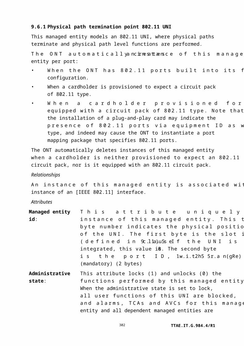
Managed entity id: This attribute uniquely identifies each instance of this managed entity. The value 0 is reserved. (R, Set-by-create) (mandatory) (2 bytes)
The four following attributes are bit maps that represent downstream mask values for subcarriers 1..128 (mask 1) through 385..512 (mask 4). The MSB of the first byte corresponds to the lowest numbered subcarrier, and the LSB of the last byte corresponds to the highest. Each bit position defines whether the corresponding downstream subcarrier is masked (1) or not masked (default value 0).
NSCds is the highest numbered subcarrier that can be transmitted in the downstream direction. For [ITU-T G.992.3], [ITU-T G.992.4], and [ITU-T G.992.5], it is defined in the corresponding Recommendation. For [ITU-T G.992.1], NSCds = 256 and for [b-ITU-T G.992.2], NSCds = 128.
Downstream subcarrier mask 1:
(R, W, Set-by-create) (mandatory) (16 bytes)
Downstream subcarrier mask 2:
Subcarriers 129 to 256. (R, W) (mandatory for modems that support NSCds > 128) (16 bytes)
Downstream subcarrier mask 3:
Subcarriers 257 to 384. (R, W) (mandatory for modems that support NSCds > 256) (16 bytes)
Downstream subcarrier mask 4:
Subcarriers 385 to 512. (R, W) (mandatory for modems that support NSCds > 384) (16 bytes)
Mask valid: This Boolean attribute controls and reports the operational status of the downstream subcarrier mask attributes.
If this attribute is true (1), the downstream subcarrier mask represented in this ME has been impressed on the DSL equipment.
If this attribute is false (0), the downstream subcarrier mask represented in this ME has not been impressed on the DSL equipment. The default value is false.
The value of this attribute can be modified by the ONT and OLT, as follows:
• If the OLT changes any of the four mask attributes or sets mask valid false, then mask valid is false.
TTAE.IT.G.984.4/R1302

• If mask valid is false and the OLT sets mask valid true, the ONT impresses the downstream subcarrier mask data onto the DSL equipment.
(R, W) (mandatory) (1 byte)
Actions
Create, delete, get, set
Notifications
None.
9.7.9 xDSL subcarrier masking upstream profile
This managed entity contains the subcarrier masking upstream profile for an xDSL line. An instance of this managed entity is created and deleted by the OLT.
Relationships
An instance of this managed entity may be associated with zero or more instances of the physical path termination point xDSL UNI.
Attributes
Managed entity id: This attribute uniquely identifies each instance of this managed entity. The value 0 is reserved. (R, Set-by-create) (mandatory) (2 bytes)
Upstream subcarrier mask:
This attribute is a bit map representing upstream mask values for subcarriers 1 to 64. The MSB of byte 1 corresponds to subcarrier 1, and the LSB of byte 8 corresponds to subcarrier 64. Each bit position defines whether the corresponding downstream subcarrier is masked (1) or not masked (default value 0).
Subcarrier number 1 is the lowest, and subcarrier number NSCus is the highest subcarrier that can be transmitted in the upstream direction. For [ITU-T G.992.3], [ITU-T G.992.4] and [ITU-T G.992.5], it is defined in the corresponding Recommendation. For Annex A of [ITU-T G.992.1] and [b-ITU-T G.992.2], NSCus = 32 and for Annex B of [ITU-T G.992.1], NSCus = 64. (R, W, Set-by-create) (mandatory) (8 bytes)
Actions
Create, delete, get, set
Notifications
TTAE.IT.G.984.4/R1303

None.
9.7.10 xDSL PSD mask profile
This managed entity contains a PSD mask profile for an xDSL line. An instance of this managed entity is created and deleted by the OLT.
NOTE 1 – This managed entity was previously known as ADSL downstream PSD mask profile. The name was changed so that the same managed entity could be used for both upstream and downstream.
Relationships
An instance of this managed entity may be associated with zero or more instances of the physical path termination point xDSL UNI.
Attributes
Managed entity id: This attribute uniquely identifies each instance of this managed entity. The value 0 is reserved. (R, Set-by-create) (mandatory) (2 bytes)
PSD mask table: This attribute is a table that defines the PSD mask applicable at the U-C2 reference point (downstream) or the U-R2 reference point (upstream). This mask may impose PSD restrictions in addition to the limit PSD mask defined in the relevant Recommendations ([ITU-T G.992.5], [ITU-T G.993.2]).
NOTE 2 – In [ITU-T G.997.1], this attribute is called PSDMASKds (downstream) and PSDMASKus (upstream). In [ITU-T G.993.2], this attribute is called MIBMASKds (downstream) and MIBMASKus (upstream). The [ITU-T G.993.2] MIBMASKus does not include breakpoints to shape US0.
The PSD mask is specified through a set of breakpoints. Each breakpoint comprises a two-byte subcarrier index t, with a subcarrier spacing of 4.3125 kHz, and a one-byte PSD mask level at that subcarrier. The set of breakpoints can then be represented as [(t1, PSD1), (t2, PSD2), … , (tN, PSDN)]. The PSD mask level is coded as 0 (0.0 dBm/Hz) to 190 (–95.0 dBm/Hz), in steps of 0.5 dB.
The maximum number of downstream breakpoints is 32. In the upstream direction, the maximum number of breakpoints is 4 for [ITU-T G.992.3] and 16 for [ITU-T G.993.2]. The requirements for a valid set of breakpoints are defined in the relevant Recommendations ([ITU-T G.992.3], [ITU-T G.992.5], [ITU-T
TTAE.IT.G.984.4/R1304

G.993.2]).
Each table entry in this attribute comprises:
• An entry number field. (1 byte, first entry numbered 1)
• A subcarrier index field, denoted t. (2 bytes)
• A PSD mask level field. (1 byte)
By default, the PSD mask table is empty. Entries are added or modified using the set action, which permits from one to as many as seven breakpoints to be addressed in a single message (Note 3). Setting a subcarrier entry with a valid PSD mask level implies insertion into the table or replacement of an existing entry. Setting an entry's PSD mask level to 0xFF implies deletion from the table.
NOTE 3 – OMCI does not provide robust exception handling when more than one entry is included in a set command, and multiple values per set operation are not recommended.
(R, W) (mandatory) (4N bytes where N is the number of breakpoints)
Mask valid: This Boolean attribute controls and reports the status of the PSD mask attribute.
As a status report, the value false (0) indicates that the PSD mask represented in this ME has not been impressed on the DSL equipment. The value true (1) indicates that the PSD mask represented in this ME has been impressed on the DSL equipment.
This attribute behaves as follows:
• If the OLT changes any of the PSD mask table entries or sets mask valid false, then mask valid is false.
• If mask valid is false and the OLT sets mask valid true, the ONT impresses the PSD mask data on the DSL equipment.
(R, W) (mandatory) (1 byte)
Actions
Create, delete, get, get next, set, Set table (optional)
Notifications
None.
TTAE.IT.G.984.4/R1305

9.7.11 xDSL downstream RFI bands profile
This managed entity contains the downstream RFI bands profile for an xDSL line. Instances of this managed entity are created and deleted by the OLT.
Relationships
An instance of this managed entity may be associated with zero or more instances of the physical path termination point xDSL UNI.
Attributes
Managed entity id: This attribute uniquely identifies each instance of this managed entity. The value 0 is reserved. (R, Set-by-create) (mandatory) (2 bytes)
Downstream RFI bands table:
The RFIBANDS attribute is a table where each entry comprises:
• An entry number field. (1 byte, first entry numbered 1)
• Subcarrier index 1 field. (2 bytes)
• Subcarrier index 2 field. (2 bytes)
For [ITU-T G.992.5], this configuration attribute defines the subset of downstream PSD mask breakpoints, as specified in the downstream PSD mask, to be used to notch an RFI band. This subset consists of couples of consecutive subcarrier indices belonging to breakpoints: [ti; ti+1], corresponding to the low level of the notch. Interpolation around these points is defined in [ITU-T G.992.5].
For [ITU-T G.993.2], this attribute defines the bands where the PSD is to be reduced as specified in clause 7.2.1.2 of [ITU-T G.993.2]. Each band is represented by start and stop subcarrier indices with a subcarrier spacing of 4.3125 kHz. Up to 16 bands may be specified. This attribute defines the RFI bands for both upstream and downstream directions.
Entries have default value 0 for both subcarrier index 1 and subcarrier index 2. Table entries for this attribute are added or modified using the set action. Setting an entry with a non-zero subcarrier index 1 and subcarrier index 2 implies insertion into the table or replacement of an existing entry. Setting an entry's subcarrier index 1 and subcarrier index 2 to 0 implies deletion from the table, if present.
TTAE.IT.G.984.4/R1306

(R, W) (mandatory) (5N bytes where N is the number of RFI bands)
Bands valid: This Boolean attribute controls and reports the operational status of the downstream RFI bands table.
If this attribute is true (1), the downstream RFI bands table has been impressed on the DSL equipment.
If this attribute is false (0), the downstream RFI bands table has not been impressed on the DSL equipment. The default value is false.
This attribute can be modified by the ONT and OLT, as follows:
• If the OLT changes any of the RFI bands table entries or sets bands valid false, then bands valid is false.
• If bands valid is false and OLT sets bands valid true, the ONT impresses the downstream RFI bands data onto the DSL equipment.
(R, W) (mandatory) (1 byte)
Actions
Create, delete, get, get next, set, Set table (optional)
Notifications
None.
9.7.12 xDSL line inventory and status data part 1
This managed entity contains part 1 of the line inventory and status data for an xDSL line. The ONT automatically creates or deletes an instance of this managed entity upon the creation or deletion of a physical path termination point xDSL UNI part 1.
Relationships
An instance of this managed entity is associated with an instance of a physical path termination point xDSL UNI part 1.
Attributes
Managed entity id: This attribute uniquely identifies each instance of this managed entity. Through an identical ID, this managed entity is implicitly linked to an instance of the physical path termination point xDSL UNI. (R) (mandatory) (2 bytes)
TTAE.IT.G.984.4/R1307

xTU-C G.994.1 vendor ID: This is the vendor ID as inserted by the xTU-C in the G.994.1 CL message. It comprises 8 octets, including a country code followed by a (regionally allocated) provider code, as defined in [ITU-T T.35]. (R) (mandatory) (8 bytes)
xTU-R G.994.1 vendor ID: This is the vendor ID as inserted by the xTU-R in the G.994.1 CLR message. It comprises 8 binary octets, with the same format as the xTU-C G.994.1 vendor ID. (R) (mandatory) (8 bytes)
xTU-C system vendor ID: This is the vendor ID as inserted by the xTU-C in the overhead messages of [ITU-T G.992.3] and [ITU-T G.992.4]. It comprises 8 binary octets, with the same format as the xTU-C G.994.1 vendor ID. (R) (mandatory) (8 bytes)
xTU-R system vendor ID: This is the vendor ID as inserted by the xTU-R in the embedded operations channel and overhead messages of [ITU-T G.992.3] and [ITU-T G.992.4]. It comprises 8 binary octets, with the same format as the xTU-C G.994.1 vendor ID. (R) (mandatory) (8 bytes)
xTU-C version number: This is the vendor-specific version number as inserted by the xTU-C in the overhead messages of [ITU-T G.992.3] and [ITU-T G.992.4]. It comprises up to 16 binary octets. (R) (mandatory) (16 bytes)
TTAE.IT.G.984.4/R1308

xTU-R version number: This is the version number as inserted by the xTU-R in the embedded operations channel of [ITU-T G.992.1] or [b-ITU-T G.992.2], or the overhead messages of [ITU-T G.992.3], [ITU-T G.992.4], [ITU-T G.992.5] and [ITU-T G.993.2]. The attribute value may be vendor-specific, but is recommended to comprise up to 16 ASCII characters, null-terminated if it is shorter than 16. The string should contain the xTU-R firmware version and the xTU-R model, encoded in that order and separated by a space character: "<xTU-R firmware version> <xTU-R model>". It is recognized that legacy xTU-Rs may not support this format. (R) (mandatory) (16 bytes)
xTU-C serial number part 1:
The vendor-specific serial number inserted by the xTU-C in the overhead messages of [ITU-T G.992.3] and [ITU-T G.992.4] comprises up to 32 ASCII characters. This attribute contains the first 16 characters. (R) (mandatory) (16 bytes)
xTU-C serial number part 2:
The vendor-specific serial number inserted by the xTU-C in the overhead messages of [ITU-T G.992.3] and [ITU-T G.992.4] comprises up to 32 ASCII characters. This attribute contains the second 16 characters. (R) (mandatory) (16 bytes)
xTU-R serial number part 1:
The serial number inserted by the xTU-R in the embedded operations channel of [ITU-T G.992.1] or [b-ITU-T G.992.2], or the overhead messages of [ITU-T G.992.3], [ITU-T G.992.4], [ITU-T G.992.5] and [ITU-T G.993.2], comprises up to 32 ASCII characters, null-terminated if it is shorter than 32. It is recommended to contain the equipment serial number, the equipment model and the equipment firmware version, encoded in that order and separated by space characters: "<equipment serial number> <equipment model> <equipment firmware version>". It is recognized that legacy xTU-Rs may not support this format. This attribute contains the first 16 characters. (R) (mandatory) (16 bytes)
xTU-R serial number part 2:
This attribute contains the second 16 characters of the xTU-R serial number. (R) (mandatory) (16 bytes)
xTU-C self test results: This parameter reports the xTU-C self test result. It is coded as a 32-bit integer. The most significant octet is 0 if the self test passed and 1 if it failed. The content of the other octets is
TTAE.IT.G.984.4/R1309

vendor-discretionary and can be interpreted in combination with [ITU-T G.994.1] and the system vendor ID. (R) (mandatory) (4 bytes)
xTU-R self test results: This parameter defines the xTU-R self test result. It is coded as a 32-bit integer. The most significant octet is 0 if the self test passed and 1 if it failed. The content of the other octets is vendor-discretionary and can be interpreted in combination with [ITU-T G.994.1] and the system vendor ID. (R) (mandatory) (4 bytes)
xTU-C transmission system capability:
This attribute lists xTU-C transmission system capabilities. It is a bit map, defined in Table 9.7.12-1.
NOTE 1 – An additional byte identifying VDSL2 capabilities is defined in the VDSL2 line inventory and status data part 1 managed entity.
(R) (mandatory) (7 bytes)
TTAE.IT.G.984.4/R1310

xTU-R transmission system capability:
This attribute lists xTU-R transmission system capabilities. It is a bit map, defined in Table 9.7.12-1.
NOTE 2 – An additional byte identifying VDSL2 capabilities is defined in the VDSL2 line inventory and status data part 2 managed entity.
(R) (mandatory) (7 bytes)
Initialization success/failure cause:
This parameter represents the success or failure cause of the last full initialization performed on the line. It is coded as follows:
0 Successful1 Configuration error
This error occurs with inconsistencies in configuration parameters, e.g., when the line is initialized in an xDSL transmission system whose xTU does not support the configured maximum delay or the configured minimum or maximum data rate for one or more bearer channels.
2 Configuration not feasible on the lineThis error occurs if the minimum data rate cannot be achieved on the line with the minimum noise margin, maximum PSD level, maximum delay and maximum bit error ratio for one or more bearer channels.
3 Communication problemThis error occurs, e.g., due to corrupted messages, bad syntax messages, if no common mode can be selected in the G.994.1 handshake procedure, or due to a timeout.
4 No peer xTU detectedThis error occurs if the peer xTU is not powered or not connected or if the line is too long to allow detection of a peer xTU.
5 Any other or unknown initialization failure cause(R) (mandatory) (1 byte)
Actions
Get
Notifications
None.
TTAE.IT.G.984.4/R1311

Table 9.7.12-1 describes the xTU transmission system capability attributes in xDSL status managed entities. It is a bit map (0 if not allowed, 1 if allowed) with the following definition.
Table 9.7.12-1 – xTU transmission system table
Bit Representation
Octet 1
1 [ANSI T1.PP.413]
2 Annex C of [ETSI TS 101 388]
3 G.992.1 operation over POTS non-overlapped spectrum (Annex A of [ITU-T G.992.1])
4 G.992.1 operation over POTS overlapped spectrum (Annex A of [ITU-T G.992.1])
5 G.992.1 operation over ISDN non-overlapped spectrum (Annex B of [ITU-T G.992.1])
6 G.992.1 operation over ISDN overlapped spectrum (Annex B of [ITU-T G.992.1])
7 G.992.1 operation in conjunction with TCM-ISDN non-overlapped spectrum (Annex C of
[ITU-T G.992.1])
8 G.992.1 operation in conjunction with TCM-ISDN overlapped spectrum (Annex C of
[ITU-T G.992.1])
Octet 2
9 G.992.2 operation over POTS non-overlapped spectrum (Annex A of [ITU-T G.992.2])
10 G.992.2 operation over POTS overlapped spectrum (Annex B of [ITU-T G.992.2])
11 G.992.2 operation in conjunction with TCM-ISDN non-overlapped spectrum (Annex C of
[ITU-T G.992.2])
12 G.992.2 operation in conjunction with TCM-ISDN overlapped spectrum (Annex C of
[b-ITU-T G.992.2])
13 Reserved
14 Reserved
15 Reserved
16 Reserved
Octet 3
17 Reserved
18 Reserved
19 G.992.3 operation over POTS non-overlapped spectrum (Annex A of [ITU-T G.992.3]).
20 G.992.3 operation over POTS overlapped spectrum (Annex A of [ITU-T G.992.3])
21 G.992.3 operation over ISDN non-overlapped spectrum (Annex B of [ITU-T G.992.3])
22 G.992.3 operation over ISDN overlapped spectrum (Annex B of [ITU-T G.992.3])
23 G.992.3 operation in conjunction with TCM-ISDN non-overlapped spectrum (Annex C of
[ITU-T G.992.3]).
24 G.992.3 operation in conjunction with TCM-ISDN overlapped spectrum (Annex C of
[ITU-T G.992.3].
Octet 4
TTAE.IT.G.984.4/R1312

Table 9.7.12-1 – xTU transmission system table
Bit Representation
25 G.992.4 operation over POTS non-overlapped spectrum (Annex A of [ITU-T G.992.4])
26 G.992.4 operation over POTS overlapped spectrum (Annex A of [ITU-T G.992.4])
27 Reserved
28 Reserved
29 G.992.3 All digital mode operation with non-overlapped spectrum (Annex I of
[ITU-T G.992.3])
30 G.992.3 All digital mode operation with overlapped spectrum (Annex I of [ITU-T G.992.3])
31 G.992.3 All digital mode operation with non-overlapped spectrum (Annex J of
[ITU-T G.992.3])
32 G.992.3 All digital mode operation with overlapped spectrum (Annex J of [ITU-T G.992.3])
Octet 5
33 G.992.4 All digital mode operation with non-overlapped spectrum (Annex I of
[ITU-T G.992.4])
34 G.992.4 All digital mode operation with overlapped spectrum (Annex I of [ITU-T G.992.4])
35 G.992.3 Reach extended operation over POTS, Mode 1 (non-overlapped, wide upstream)
(Annex L of [ITU-T G.992.3])
36 G.992.3 Reach extended operation over POTS, Mode 2 (non-overlapped, narrow upstream)
(Annex L of [ITU-T G.992.3])
37 G.992.3 Reach extended operation over POTS, Mode 3 (overlapped, wide upstream)
(Annex L of [ITU-T G.992.3])
38 G.992.3 Reach extended operation over POTS, Mode 4 (overlapped, narrow upstream)
(Annex L of [ITU-T G.992.3])
39 G.992.3 Extended upstream operation over POTS non-overlapped spectrum (Annex M of
[ITU-T G.992.3])
40 G.992.3 Extended upstream operation over POTS overlapped spectrum (Annex M of
[ITU-T G.992.3])
Octet 6
41 G.992.5 operation over POTS non-overlapped spectrum (Annex A of [ITU-T G.992.5])
42 G.992.5 operation over POTS overlapped spectrum (Annex A of [ITU-T G.992.5])
43 G.992.5 operation over ISDN non-overlapped spectrum (Annex B of [ITU-T G.992.5])
44 G.992.5 operation over ISDN overlapped spectrum (Annex B of [ITU-T G.992.5])
45 G.992.5 operation in conjunction with TCM-ISDN non-overlapped spectrum (Annex C of
[ITU-T G.992.5]).
46 G.992.5 operation in conjunction with TCM-ISDN overlapped spectrum (Annex C of [ITU-T
G.992.5]).
47 G.992.5 All digital mode operation with non-overlapped spectrum (Annex I of
TTAE.IT.G.984.4/R1313

Table 9.7.12-1 – xTU transmission system table
Bit Representation
[ITU-T G.992.5])
48 G.992.5 All digital mode operation with overlapped spectrum (Annex I of [ITU-T G.992.5])
Octet 7
49 G.992.5 All digital mode operation with non-overlapped spectrum (Annex J of
[ITU-T G.992.5])
50 G.992.5 All digital mode operation with overlapped spectrum (Annex J of [ITU-T G.992.5])
51 G.992.5 Extended upstream operation over POTS non-overlapped spectrum (Annex M of
[ITU-T G.992.5])
52 G.992.5 Extended upstream operation over POTS overlapped spectrum (Annex M of
[ITU-T G.992.5])
53 Reserved
54 Reserved
55 Reserved
56 Reserved
Octet 8
(Note)
57 G.993.2 region A (North America) (Annex A of [ITU-T G.993.2])
58 G.993.2 region B (Europe) (Annex B of [ITU-T G.993.2])
59 G.993.2 region C (Japan) (Annex C of [ITU-T G.993.2])
60 Reserved
61 Reserved
62 Reserved
63 Reserved
64 Reserved
NOTE – For backward compatibility reasons, the eighth octet of this table is represented as a separate
attribute in separate managed entities.
9.7.13 xDSL line inventory and status data part 2
This managed entity contains part 2 of the line inventory and status data for an xDSL line. The ONT automatically creates or deletes an instance of this managed entity upon the creation or deletion of a physical path termination point xDSL UNI part 1.
NOTE 1 – [ITU-T G.997.1] specifies that bit rate attributes have granularity of 1000 bit/s. If G.997.1 compliance is required, the ONT should only report values with this granularity.
Relationships
TTAE.IT.G.984.4/R1314

An instance of this managed entity is associated with an instance of a physical path termination point xDSL UNI part 1.
Attributes
Managed entity id: This attribute uniquely identifies each instance of this managed entity. Through an identical ID, this managed entity is implicitly linked to an instance of the physical path termination point xDSL UNI. (R) (mandatory) (2 bytes)
xDSL transmission system: This parameter defines the transmission system in use. It is a bit map, defined in Table 9.7.12-1. (R) (mandatory) (7 bytes)
NOTE 2 – An additional byte identifying VDSL2 capabilities in use is defined in the VDSL2 line inventory and status data part 1 managed entity.(R) (mandatory) (7 bytes)
Line power management state:
The line has four possible power management states:
0 L0: Synchronized – This line state occurs when the line has full transmission (i.e., showtime).
1 L1: Power down data transmission – This line state occurs when there is transmission on the line but the net data rate is reduced (e.g., only for OAM and higher layer connection and session control). This state applies to [b-ITU-T G.992.2] only.
2 L2: Power down data transmission – This line state occurs when there is transmission on the line but the net data rate is reduced (e.g., only for OAM and higher layer connection and session control). This state applies to [ITU-T G.992.3] and [ITU-T G.992.4] only.
3 L3: No power – This line state occurs when no power is transmitted on the line at all.
(R) (mandatory) (1 byte)
TTAE.IT.G.984.4/R1315
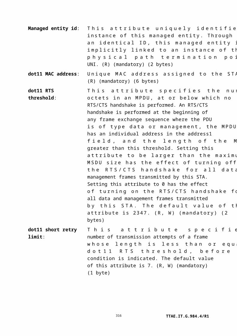
Downstream line attenuation:
The LATNds attribute is the measured difference in the total power transmitted by the xTU-C and the total power received by the xTU-R over all subcarriers during diagnostics mode and initialization. The attribute value ranges from 0 (0.0 dB) to 1270 (127.0 dB) dB. The special value 0xFFFF indicates that line attenuation is out of range.
NOTE 3 – [ITU-T G.993.2] specifies a per-band array to represent this attribute. The array is defined in the VDSL2 line inventory and status data part 3 managed entity. In a G.993.2 context, the downstream line attenuation attribute should be set to 0 here, and populated in the VDSL2 line inventory and status data part 3 ME instead.
(R) (mandatory) (2 bytes)
Upstream line attenuation: The LATNus attribute is the measured difference in the total power transmitted by the xTU-R and the total power received by the xTU-C over all subcarriers during diagnostics mode and initialization. The attribute value ranges from 0 (0.0 dB) to 1270 (127.0 dB). The special value 0xFFFF indicates that line attenuation is out of range.
NOTE 4 – [ITU-T G.993.2] specifies a per-band array to represent this attribute. The array is defined in the VDSL2 line inventory and status data part 3 managed entity. In a G.993.2 context, the upstream line attenuation attribute should be set to 0 here, and populated in the VDSL2 line inventory and status data part 3 ME instead. (R) (mandatory) (2 bytes)
Downstream signal attenuation:
The SATNds attribute is the measured difference in the total power transmitted by the xTU-C and the total power received by the xTU-R over all subcarriers during showtime. The attribute value ranges from 0 (0.0 dB) to 1270 (127.0 dB). The special value 0xFFFF indicates that signal attenuation is out of range.
NOTE 5 – [ITU-T G.993.2] specifies a per-band array to represent this attribute. The array is defined in the VDSL2 line inventory and status data part 3 managed entity. In a [ITU-T G.993.2] context, the downstream signal attenuation attribute should be set to 0 here, and populated in the VDSL2
TTAE.IT.G.984.4/R1316

line inventory and status data part 3 ME instead. (R) (mandatory) (2 bytes)
Upstream signal attenuation:
The SATNus attribute is the measured difference in the total power transmitted by the xTU-R and the total power received by the xTU-C over all subcarriers during showtime. The attribute value ranges from 0 (0.0 dB) to 1270 (127.0 dB). The special value 0xFFFF indicates that signal attenuation is out of range.
NOTE 6 – [ITU-T G.993.2] specifies a per-band array to represent this attribute. The array is defined in the VDSL2 line inventory and status data part 3 managed entity. In a [ITU-T G.993.2] context, the upstream signal attenuation attribute should be set to 0 here, and populated in the VDSL2 line inventory and status data part 3 ME instead. (R) (mandatory) (2 bytes)
Downstream signal-to-noise ratio margin:
The downstream signal-to-noise ratio margin SNRMds is the maximum increase of noise power received at the xTU-R, such that the BER requirements can still be met for all downstream bearer channels. The attribute value ranges from 0 (–64.0 dB) to 1270 (+63.0 dB). The special value 0xFFFF indicates that the attribute is out of range. (R) (mandatory) (2 bytes)
Upstream signal-to-noise ratio margin:
The upstream signal-to-noise ratio margin SNRMus is the maximum increase of noise power received at the xTU-C, such that the BER requirements can still be met for all upstream bearer channels. The attribute value ranges from 0 (–64.0 dB) to 1270 (+63.0 dB). The special value 0xFFFF indicates that the attribute is out of range. (R) (mandatory) (2 bytes)
Downstream maximum attainable data rate:
This parameter indicates the maximum downstream net data rate currently attainable. The rate is coded in bit/s. (R) (mandatory) (4 bytes)
Upstream maximum attainable data rate:
This parameter indicates the maximum upstream net data rate currently attainable. The rate is coded in bit/s. (R) (mandatory) (4 bytes)
Downstream actual power spectrum density:
This parameter is the average downstream transmit power spectrum density over the subcarriers in use (subcarriers to
TTAE.IT.G.984.4/R1317

which downstream user data are allocated) delivered by the xTU-C at the U-C reference point, at the instant of measurement. The attribute value ranges from 0 (–90.0 dBm/Hz) to 900 (0.0 dBm/Hz). The special value 0xFFFF indicates that the parameter is out of range. (R) (mandatory) (2 bytes)
Upstream actual power spectrum density:
The ACTPSDus attribute is the average upstream transmit power spectrum density over the subcarriers in use (subcarriers to which upstream user data are allocated) delivered by the xTU-R at the U-R reference point, at the instant of measurement. The attribute value ranges from 0 (–90.0 dBm/Hz) to 900 (0.0 dBm/Hz). The special value 0xFFFF indicates that the attribute is out of range. (R) (mandatory) (2 bytes)
Downstream actual aggregate transmit power:
This parameter is the total amount of transmit power delivered by the xTU-C at the U-C reference point, at the instant of measurement. The attribute value ranges from 0 (–31.0 dBm ) to 620 (+31.0 dBm). The special value 0xFFFF indicates that the parameter is out of range.
NOTE 7 – The downstream nominal aggregate transmit power may be taken as a best estimate of the parameter.
(R) (mandatory) (2 bytes)
Upstream actual aggregate transmit power:
This parameter is the total amount of transmit power delivered by the xTU-R at the U-R reference point, at the instant of measurement. The attribute value ranges from 0 (–31.0 dBm ) to 620 (+31.0 dBm). The special value 0xFFFF indicates that the parameter is out of range.
NOTE 8 – The upstream nominal aggregate transmit power may be taken as a best estimate of the parameter.
(R) (mandatory) (2 bytes)
Initialization – last state transmitted downstream:
This parameter represents the last successful transmitted initialization state in the downstream direction in the last full initialization performed on the line. Initialization states are defined in the individual xDSL Recommendations and are counted from 0 (if [ITU-T G.994.1] is used) or 1 (if [ITU-T G.994.1] is not used) up to showtime. This parameter must be interpreted along with the xDSL transmission system
TTAE.IT.G.984.4/R1318

capabilities.
This parameter is available only when, after a failed full initialization, line diagnostic procedures are activated on the line. Line diagnostic procedures can be activated by the operator of the system (through the line state forced line configuration parameter) or autonomously by the xTU-C or xTU-R.
(R) (mandatory) (1 byte)
Initialization – last state transmitted upstream:
This parameter represents the last successful transmitted initialization state in the upstream direction in the last full initialization performed on the line. Initialization states are defined in the individual xDSL Recommendations and are counted from 0 (if [ITU-T G.994.1] is used) or 1 (if [ITU-T G.994.1] is not used) up to showtime. This parameter must be interpreted along with the xDSL transmission system capabilities.
This parameter is available only when, after a failed full initialization, line diagnostic procedures are activated on the line. Line diagnostic procedures can be activated by the operator of the system (through the line state forced line configuration parameter) or autonomously by the xTU-C or xTU-R.
(R) (mandatory) (1 byte)
Actions
Get
Notifications
None.
9.7.14 xDSL line inventory and status data part 3
This managed entity extends the attributes defined in the xDSL line inventory and status data parts 1 and 2. This ME reports downstream attributes.
Relationships
This is one of the status MEs pointed to by a physical path termination point xDSL managed entity. The ONT automatically creates or deletes an instance of this managed entity upon creation or deletion of a physical path termination point xDSL that supports these attributes.
TTAE.IT.G.984.4/R1319

Attributes
Managed entity id: This attribute uniquely identifies each instance of this managed entity. Through an identical ID, this managed entity is implicitly linked to an instance of the physical path termination point xDSL managed entity. (R) (mandatory) (2 bytes)
TSSpsds table: This table contains downstream transmit spectrum shaping attributes expressed as the set of breakpoints exchanged during [ITU-T G.994.1]. Each breakpoint consists of a two-byte subcarrier index and the associated shaping attribute. The shaping attribute is one byte, an integer value in the 0 to 126 range, represented as a multiple of –0.5 dB. The special value 127 indicates that the subcarrier is not transmitted. (R) (mandatory) (3N bytes, where N is the number of breakpoints)
HLINSCds: This attribute is the scale factor to be applied to the downstream Hlin(f) values. It is coded as a 16-bit unsigned integer. This attribute is only available after a loop diagnostic procedure. (R) (mandatory) (2 bytes)
HLINpsds table: This attribute is an array of complex coefficients {a, b} that represent the downstream transfer function Hlin(f) in linear form. Each array entry represents Hlin(f ) = i*HLINGds*f for a particular subcarrier group index i, ranging from 0 to min(NSds, 511). Hlin(f) may be reconstructed from the array as ((HLINSCds/215)*((a(i) + j*b(i))/215)), where a(i) and b(i) are 2s complement integers in the range (–215 + 1) to (+215 – 1). The granularity of a and b depends on the scale factor.
The special value a(i) = b(i) = –215 indicates that no measurement could be done for this subcarrier group because it is out of the passband or that the attenuation is out of range to be represented.
This attribute is only available after a loop diagnostic procedure. (R) (mandatory) (4N bytes, where N is the number of subcarrier groups)
HLOGMTds: After a loop diagnostic procedure, this attribute contains the number of symbols used to measure the downstream Hlog(f) values. It is a 16-bit unsigned value that corresponds to the
TTAE.IT.G.984.4/R1320

value specified in the corresponding Recommendation (e.g., the number of symbols in a one-second interval for [ITU-T G.992.3]). (R) (mandatory) (2 bytes)
HLOGpsds table: The HLOGpsds attribute contains an array of numbers m(i), where i is a particular subcarrier group index, ranging from 0 to min(NSds, 511), and m lies in the range 0..1022, with a granularity of 0.1 dB. The downstream transfer function Hlog(f) can be reconstructed by the OLT management client as (6 – m(i)/10) dBm/Hz, with a range from +6 to approximately –96 dBm/Hz.
The special value m = 1023 indicates that no measurement could be done for this subcarrier group because it is out of the passband or that the attenuation is out of range to be represented.
(R) (mandatory) (2N bytes, where N is the number of subcarrier groups)
QLNMTds: After a loop diagnostic procedure, the quiet line noise PSD measurement time attribute contains the number of symbols used to measure the downstream QLN(f) values. It is a 16-bit unsigned value that corresponds to the value specified in the Recommendation (e.g., the number of symbols in a one-second interval for [ITU-T G.992.3]). (R) (mandatory) (2 bytes)
QLNpsds table: The quiet line noise PSD attribute contains an array of numbers n(i), where i is a subcarrier group index, ranging from 0 to min(NSds, 511), and n lies in the range 0..254, with granularity 0.5 dB. The downstream quiet line noise function QLN(f ) can be reconstructed by the OLT management client as (–23 – n(i)/2) dBm/Hz, with a range from –150 to –23 dBm/Hz.
TTAE.IT.G.984.4/R1321

The special value n = 255 indicates that no measurement could be done for this subcarrier group because it is out of the passband or that the noise PSD is out of range to be represented.
(R) (mandatory) (N bytes, where N is the number of subcarrier groups)
SNRMTds: After a loop diagnostic procedure, the SNR measurement time attribute contains the number of symbols used to measure the downstream SNR(f) values. It is a 16-bit unsigned value that corresponds to the value specified in the Recommendation (e.g., the number of symbols in a one-second interval for [ITU-T G.992.3]). (R) (mandatory) (2 bytes)
SNRpsds table: The SNRpsds attribute contains an array of numbers snr(i), where i is a subcarrier group index, ranging from 0 to min(NSds, 511), and snr lies in the range 0..254, with a granularity of 0.5 dB. The downstream SNR function SNR(f), can be reconstructed by the OLT management client as (–32 + snr(i)/2) dBm/Hz, with a range from –160 to –32 dBm/Hz.
The special value snr = 255 indicates that no measurement could be done for this subcarrier group because it is out of the passband or that the noise PSD is out of range to be represented.
(R) (mandatory) (N bytes, where N is the number of subcarrier groups)
BITSpsds table: This attribute reports the downstream bits allocation table per subcarrier. It is an array of values in the range 0..15 for subcarriers 0..NSds. Entries for subcarriers out of the downstream medley set are set to 0. (R) (mandatory) (N bytes, where N is the number of subcarriers)
GAINSpsds table: This attribute contains the downstream gain allocation table per subcarrier. It is an array of integer values in the range 0..4093 for subcarriers 0..NSds. The gain is represented as a multiple of 1/512 on a linear scale. Entries for subcarriers out of the downstream medley set are set to 0. (R) (mandatory) (2N bytes, where N is the number of subcarriers)
TTAE.IT.G.984.4/R1322

Actions
Get, get next
Notifications
None.
9.7.15 xDSL line inventory and status data part 4
This managed entity extends the attributes defined in the xDSL line inventory and status data parts 1, 2 and 3. This ME reports upstream attributes.
Relationships
This is one of the status data MEs pointed to by a physical path termination point xDSL managed entity. The ONT automatically creates or deletes an instance of this managed entity upon creation or deletion of a physical path termination point xDSL that supports these attributes.
Attributes
Managed entity id: This attribute uniquely identifies each instance of this managed entity. Through an identical ID, this managed entity is implicitly linked to an instance of the physical path termination point xDSL managed entity. (R) (mandatory) (2 bytes)
TSSpsus table: This attribute contains the upstream transmit spectrum shaping attributes, expressed as the set of breakpoints exchanged during [ITU-T G.994.1]. Each breakpoint consists of a two-byte subcarrier index and the associated shaping attribute. The shaping attribute is one byte, a value in the range 0..126, representing a multiple of –0.5 dB. The special value 127 indicates that the subcarrier is not transmitted. (R) (mandatory) (3N bytes, where N is the number of breakpoints)
HLINSCus: This attribute is a 16-bit unsigned integer, the scale factor to be applied to the upstream Hlin(f) values. It is only available after a loop diagnostic procedure. (R) (mandatory) (2 bytes)
HLINpsus table: This attribute is an array of complex upstream Hlin(f) values in linear scale. It is coded in the same way as the related downstream attribute HLINpsds (see xDSL line inventory and status data part 3). This attribute is only available after a loop diagnostic procedure. (R) (mandatory) (4N bytes, where N is
TTAE.IT.G.984.4/R1323

the number of subcarrier groups)
HLOGMTus: After a loop diagnostic procedure, this attribute contains the number of symbols used to measure the upstream Hlog(f) values. Its value corresponds to the value specified in the corresponding Recommendation (e.g., the number of symbols in a 1-second interval for [ITU-T G.992.3]). (R) (mandatory) (2 bytes)
HLOGpsus table: This attribute is an array of real upstream Hlog(f) values. It is coded in the same way as the related downstream attribute HLOGpsds (see xDSL line inventory and status data part 3). (R) (mandatory) (2N bytes, where N is the number of subcarrier groups)
QLNMTus: After a loop diagnostic procedure, the quiet line noise PSD measurement attribute contains the number of symbols used to measure the upstream QLN(f) values. Its value corresponds to the value specified in the Recommendation (e.g., the number of symbols in a 1-second interval for [ITU-T G.992.3]). (R) (mandatory) (2 bytes)
QLNpsus table: The quiet line noise attribute represents an array of real upstream QLN(f) values. It is coded in the same way as the related downstream attribute QLNpsds (see xDSL line inventory and status data part 3). (R) (mandatory) (N bytes, where N is the number of subcarrier groups)
SNRMTus: After a loop diagnostic procedure, the SNR measurement time attribute reports the number of symbols used to measure the upstream SNR(f) values. Its value corresponds to the value specified in the Recommendation (e.g., the number of symbols in a 1-second interval for [ITU-T G.992.3]). (R) (mandatory) (2 bytes)
TTAE.IT.G.984.4/R1324

SNRpsus table: This attribute is an array of real upstream SNR(f) values. It is coded in the same way as the related downstream attribute SNRpsds (see xDSL line inventory and status data part 3). (R) (mandatory) (N bytes, where N is the number of subcarrier groups)
BITSpsus table: This attribute contains the upstream bits allocation table per subcarrier. It is an array in the range 0..15 for subcarriers 0..NSus. Entries for subcarriers out of the upstream medley set are set to 0. (R) (mandatory) (N bytes, where N is the number of subcarriers)
GAINSpsus table: This attribute contains the upstream gains allocation table per subcarrier. It is an array in the range 0..4093 for subcarriers 0..NSus. The gain is represented as a multiple of 1/512 on a linear scale. Entries for subcarriers out of the upstream medley set are set to 0. (R) (mandatory) (2N bytes, where N is the number of subcarriers)
Actions
Get, get next
Notifications
None.
9.7.16 VDSL2 line inventory and status data part 1
This managed entity extends the other xDSL line inventory and status data MEs with attributes specific to VDSL2. Due to continuing standards development, some attributes – and therefore this managed entity – have also become applicable to other Recommendations, specifically [ITU-T G.992.3] and [ITU-T G.992.5]. This ME contains general and downstream attributes.
Relationships
This is one of the status data MEs pointed to by a physical path termination point xDSL managed entity. It is meaningful if the PPTP supports [ITU-T G.992.3] and [ITU-T G.992.5] or [ITU-T G.993.2]. The ONT automatically creates or deletes an instance of this managed entity upon creation and deletion of a physical path termination point xDSL that supports these attributes.
Attributes
Managed entity id: This attribute uniquely identifies each instance of this managed entity. Through an identical ID, this managed entity
TTAE.IT.G.984.4/R1325

is implicitly linked to an instance of the physical path termination point xDSL managed entity. (R) (mandatory) (2 bytes)
VDSL2 transmission system capability xTU-C:
This attribute extends the xTU-C transmission system capability attribute of the xDSL line inventory and status data part 1 to include xTU-C VDSL2 capabilities. It is defined by bits 57..64 of Table 9.7.12-1. (R) (mandatory) (1 byte)
VDSL2 transmission system:This attribute reports the transmission system in use. It extends the xDSL transmission system attribute of the xDSL line inventory and status data part 2 managed entity with a byte that includes VDSL2 capabilities currently in use. It is defined by bits 57..64 of Table 9.7.12-1. (R) (mandatory) (1 byte)
VDSL2 profile: This attribute identifies the profile in use. It is a bit map (0 if not allowed, 1 if allowed) with the following definition:
Bit Meaning
1 (LSB) G.993.2 profile 8a.2 G.993.2 profile 8b.3 G.993.2 profile 8c.4 G.993.2 profile 8d.5 G.993.2 profile 12a.6 G.993.2 profile 12b.7 G.993.2 profile 17a.8 G.993.2 profile 30a.
(R) (mandatory) (1 byte)
VDSL2 limit PSD mask and bandplan:
This attribute defines the limit PSD mask and band plan in use. It is a bit map as defined by Table 9.7.6-1. (R) (mandatory) (8 bytes)
VDSL2 US0 PSD mask: This attribute defines the US0 PSD mask in use. It is a bit map as defined by Table 9.7.6-2. (R) (mandatory) (4 bytes)
TTAE.IT.G.984.4/R1326

ACTSNRMODEds: This attribute indicates whether transmitter referred virtual noise is active on the line in the downstream direction.
1 Virtual noise inactive.2 Virtual noise active.
(R) (mandatory) (1 byte)
The following four attributes have similar definitions. In each case, valid attribute values are 1, 2, 4, 8. In ADSL applications, the corresponding value is fixed at 1, and therefore need not be specified. For VDSL2, it is equal to the size of the subcarrier group used to compute these attributes (see clause 11.4.1 of [ITU-T G.993.2]).
HLINGds: This attribute contains the number of subcarriers per group used to report HLINpsds. (R) (mandatory) (1 byte)
HLOGGds: This attribute contains the number of subcarriers per group used to report HLOGpsds. (R) (mandatory) (1 byte)
QLNGds: This attribute contains the number of subcarriers per group used to report QLNpsds. (R) (mandatory) (1 byte)
SNRGds: This attribute contains the number of subcarriers per group used to report SNRpsds. (R) (mandatory) (1 byte)
MREFPSDds table: The downstream medley reference PSD table contains the set of breakpoints exchanged in the MREFPSDds fields of the O-PRM message of [ITU-T G.993.2].
The format is similar to that specified for the PSD descriptor in [ITU-T G.993.2]. In [ITU-T G.993.2], the first byte gives the size of the table, each entry of which is three bytes. In the OMCI definition, the first byte is omitted, because the size of the table is known from the response to the get command.
(R) (mandatory) (3N bytes, where N is the number of breakpoints)
TRELLISds: This attribute reports whether trellis coding is in use in the downstream direction.
0 Trellis not used.1 Trellis used.
(R) (mandatory for [ITU-T G.993.2] VDSL2, optional for others) (1 byte)
TTAE.IT.G.984.4/R1327

Actual rate adaptation mode downstream:
The ACT-RA-MODEds attribute indicates the actual active RA mode in the downstream direction.
1 MANUAL2 AT_INIT3 DYNAMIC4 DYNAMIC with SOS ([ITU-T G.993.2] only)
(R) (optional) (1 byte)
Actual impulse noise protection ROC downstream:
The ACTINP-ROC-ds attribute reports the actual impulse noise protection (INP) of the robust operations channel ROC in the downstream direction. The format and usage is identical to that of the ACTINP attribute defined in the xDSL channel downstream status data ME. (R) (optional) (1 byte)
SNR margin ROC downstream:
The SNRM-ROC-ds attribute reports the actual signal-to-noise margin of the ROC in the downstream direction. Its value ranges from 0 (–64.0 dB) to 1270 (+63.0 dB). The special value 0xFFFF indicates that the attribute is out of range. (R) (optional) (2 bytes)
Actions
Get, get next
Notifications
None.
9.7.17 VDSL2 line inventory and status data part 2
This managed entity extends the xDSL line configuration MEs. The ME name was chosen because its attributes were initially unique to ITU-T G.993.2 VDSL2. Due to continuing standards development, some attributes – and therefore this managed entity – have also become applicable to other Recommendations, specifically [ITU-T G.992.3] and [ITU-T G.992.5].
This ME contains upstream attributes.
Relationships
This is one of the status data MEs associated with an xDSL UNI. It is meaningful if the PPTP supports [ITU-T G.992.3], [ITU-T G.992.5] or [ITU-T G.993.2]. The ONT automatically creates or deletes an instance of this managed entity upon creation and deletion of a physical path termination point xDSL UNI part 1 that supports these attributes.
Attributes
TTAE.IT.G.984.4/R1328

Managed entity id: This attribute uniquely identifies each instance of this managed entity. Through an identical ID, this managed entity is implicitly linked to an instance of the physical path termination point xDSL managed entity. (R) (mandatory) (2 bytes)
VDSL2 transmission system capability xTU-R:
This attribute extends the xTU-R transmission system capability attribute of the xDSL line inventory and status data part 1 to include xTU-R VDSL2 capabilities. It is a bit map, specifically bits 57..64 of Table 9.7.12-1. (R) (mandatory) (1 byte)
ACTSNRMODEus: This attribute indicates whether transmitter referred virtual noise is active on the line in the upstream direction.
1 Virtual noise inactive.2 Virtual noise active.
(R) (mandatory) (1 byte)
UPBOKLE: This attribute contains the electrical length estimated by the VTU-O expressed in dB at 1 MHz, kl0 (see O-UPDATE in clause 12.3.3.2.1.2 of [ITU-T G.993.2]). This is the final electrical length that would have been sent from the VTU-O to the VTU-R if the electrical length were not forced by the OLT. The value lies in the range 0 (0.0 dB) to 1280 (128.0 dB) (R) (mandatory) (2 bytes)
HLINGus: This attribute is the number of subcarriers per group used to report HLINpsus. (R) (mandatory) (1 byte)
HLOGGus: This attribute is the number of subcarriers per group used to report HLOGpsus. (R) (mandatory) (1 byte)
QLNGus: This attribute is the number of subcarriers per group used to report QLNpsus. (R) (mandatory) (1 byte)
SNRGus: This attribute is the number of subcarriers per group used to report SNRpsus. (R) (mandatory) (1 byte)
TTAE.IT.G.984.4/R1329

MREFPSDus table: The upstream medley reference PSD attribute contains the set of breakpoints exchanged in the MREFPSDus fields of the R-PRM message of [ITU-T G.993.2].
The format is similar to that specified for the PSD descriptor in [ITU-T G.993.2]. In [ITU-T G.993.2], the first byte gives the size of the table, each entry of which is three bytes. In the OMCI definition, the first byte is omitted, because the size of the table is known from the response to the get command.
(R) (mandatory) (3N bytes, where N is the number of breakpoints)
TRELLISus: This attribute reports whether trellis coding is in use in the upstream direction.
0 Trellis not used.1 Trellis used.
(R) (mandatory for [ITU-T G.993.2] VDSL2, optional for others) (1 byte)
ACTUALCE: This attribute reports the cyclic extension used on the line. It is coded as an unsigned integer from 2 to 16 in units of N/32 samples, where 2N is the IDFT size. (R) (mandatory) (1 byte)
UPBOKLE-R: This attribute contains the electrical length estimated by the VTU-R expressed in dB at 1 MHz. This is the value contained in the message R-MSG1 (see clause 12.3.3.2.2.1 of [ITU-T G.993.2]). Its value lies in the range 0 (0.0 dB) to 1280 (128.0 dB) (R) (optional) (2 bytes)
Actual rate adaptation mode upstream:
The ACT-RA-MODEus attribute indicates the actual active RA mode in the upstream direction.
1 MANUAL2 AT_INIT3 DYNAMIC4 DYNAMIC with SOS ([ITU-T G.993.2] only)
(R) (optional) (1 byte)
Actual impulse noise protection ROC upstream:
The ACTINP-ROC-us attribute reports the actual impulse noise protection (INP) of the robust operations channel ROC in the upstream direction. The format and usage is identical to that of the ACTINP attribute defined in the xDSL channel upstream status data ME. (R) (optional) (1 byte)
TTAE.IT.G.984.4/R1330

SNR margin ROC upstream:
The SNRM-ROC-us attribute reports the actual signal-to-noise margin of the ROC in the upstream direction. Its value ranges from 0 (–64.0 dB) to 1270 (+63.0 dB). The special value 0xFFFF indicates that the attribute is out of range. (R) (optional) (2 bytes)
Actions
Get, get next
Notifications
None.
9.7.18 VDSL2 line inventory and status data part 3
This managed entity extends the other xDSL line inventory and status data MEs with attributes specific to VDSL2. This ME contains per-band attributes for both directions. These same attributes are defined in the xDSL line inventory and status data part 2 managed entity, but only for a single band. [ITU-T G.993.2] allows for VDSL2 to have as many as five bands upstream and as many as five bands downstream.
Relationships
This is one of the status data MEs pointed to by a physical path termination point xDSL managed entity. It is required only if VDSL2 is supported by the PPTP. The ONT automatically creates or deletes an instance of this managed entity upon creation or deletion of a physical path termination point xDSL that supports these attributes.
Attributes
Managed entity id: This attribute uniquely identifies each instance of this managed entity. Through an identical ID, this managed entity is implicitly linked to an instance of the physical path termination point xDSL managed entity. (R) (mandatory) (2 bytes)
TTAE.IT.G.984.4/R1331

Upstream bands count: This attribute reports the number of upstream bands. It can be used to filter the upstream attributes. All upstream attributes are arrays of per-band entries, of which the first upstream bands count are populated. The content of the arrays for unused frequency bands is unspecified. The original attributes were allocated for as many as four upstream bands, US0, 1, 2, 3; optional extended attributes have been added to accommodate the possibility that five upstream bands may be needed. (R) (mandatory) (1 byte)
Downstream bands count: This attribute reports the number of downstream bands. It can be used to filter the downstream attributes. All downstream attributes are arrays of per-band entries, of which the first downstream bands count are populated. The content of the arrays for unused frequency bands is unspecified. The original attributes were allocated for as many as three upstream bands, DS1, 2, 3; optional extended attributes have been added to accommodate the possibility that five downstream bands may be needed. (R) (mandatory) (1 byte)
Downstream line attenuation per band:
The LATNds attribute is defined per usable band. It is the measured difference in the total power transmitted in this band by the xTU-C and the total power received in this band by the xTU-R over all subcarriers of this band during loop diagnostic mode and initialization. The upstream line attenuation per band ranges from 0 (0.0 dB) to 1270 (+127.0 dB). The special value 0xFFFF indicates the line attenuation per band is out of range to be represented. (R) (mandatory) (3 bands * 2 bytes = 6 bytes)
Upstream line attenuation per band:
The LATNus attribute is defined per usable band. It is the measured difference in the total power transmitted in this band by the xTU-R and the total power received in this band by the xTU-C over all subcarriers of this band during loop diagnostic mode and initialization. The upstream line attenuation per band ranges from 0 (0.0 dB) to 1270 (+127.0 dB). The special value 0xFFFF indicates that line attenuation per band is out of range to be represented. (R) (mandatory) (4 bands * 2 bytes = 8 bytes)
Downstream signal attenuation per band:
The SATNds attribute is defined per usable band. It is the measured difference in the total power transmitted in this
TTAE.IT.G.984.4/R1332

band by the xTU-C and the total power received in this band by the xTU-R over all subcarriers of this band during showtime. The downstream signal attenuation per band ranges from 0 (0.0 dB) to 1270 (+127.0 dB). The special value 0xFFFF indicates that signal attenuation per band is out of range to be represented.
NOTE 1 – During showtime, only a subset of the subcarriers may be transmitted by the xTU-C, as compared to loop diagnostic mode and initialization. Therefore, the downstream signal attenuation may be significantly lower than the downstream line attenuation.
(R) (mandatory) (3 bands * 2 bytes = 6 bytes)
Upstream signal attenuation per band:
The SATNus attribute is defined per usable band. It is the measured difference in the total power transmitted in this band by the xTU-R and the total power received in this band by the xTU-C over all subcarriers of this band during showtime. The upstream signal attenuation per band ranges from 0 (0.0 dB) to 1270 (+127.0 dB). The special value 0xFFFF indicates the signal attenuation per band is out of range to be represented.
NOTE 2 – During showtime, only a subset of the subcarriers may be transmitted by the xTU-R, as compared to loop diagnostic mode and initialization. Therefore, the upstream signal attenuation may be significantly lower than the upstream line attenuation.
(R) (mandatory) (4 bands * 2 bytes = 8 bytes)
Downstream signal-to-noise ratio margin per band:
The SNRMpbds attribute is defined per usable band. The downstream signal to noise ratio margin per band is the maximum increase of noise power received at the xTU-R, such that the BER requirements are met for all downstream bearer channels. Each array value ranges from 0 (–64.0 dB) to 1270 (+63.0 dB). The special value 0xFFFF indicates that the attribute is out of range to be represented. (R) (mandatory) (3 bands * 2 bytes = 6 bytes)
Upstream signal-to-noise ratio margin per band:
The SNRMpbus attribute is defined per usable band. The upstream signal to noise ratio margin per band is the maximum increase of noise power received at the xTU-C,
TTAE.IT.G.984.4/R1333

such that the BER requirements are met for all upstream bearer channels. Each array value ranges from 0 (–64.0 dB) to 1270 (+63.0 dB). The special value 0xFFFF indicates that the attribute is out of range to be represented. (R) (mandatory) (4 bands * 2 bytes = 8 bytes)
Downstream line attenuation extension:
This attribute extends LATNds when more than three downstream bands are used. It is defined in the same way as the downstream line attenuation per band attribute. (R) (optional) (2 bands * 2 bytes = 4 bytes)
Upstream line attenuation extension:
This attribute extends LATNus when more than four upstream bands are used. It is defined in the same way as the upstream line attenuation per band attribute. (R) (optional) (1 band * 2 bytes = 2 bytes)
Downstream signal attenuation extension:
This attribute extends SATNds when more than three downstream bands are used. It is defined in the same way as the downstream signal attenuation per band attribute. (R) (optional) (2 bands * 2 bytes = 4 bytes)
Upstream signal attenuation extension:
This attribute extends SATNus when more than four upstream bands are used. It is defined in the same way as the upstream signal attenuation per band attribute. (R) (optional) (1 band * 2 bytes = 2 bytes)
Downstream signal-to-noise ratio margin extension:
This attribute extends SNRMpbds when more than three downstream bands are used. It is defined in the same way as the downstream signal-to-noise ratio margin per band attribute. (R) (optional) (2 bands * 2 bytes = 4 bytes)
Upstream signal-to-noise ratio margin extension:
This attribute extends SNRMpbus when more than four upstream bands are used. It is defined in the same way as the upstream signal-to-noise ratio margin per band attribute. (R) (optional) (1 band * 2 bytes = 2 bytes)
Actions
Get
Notifications
None.
TTAE.IT.G.984.4/R1334

9.7.19 xDSL channel downstream status data
This managed entity contains the xDSL channel downstream status data for an xDSL line. The ONT automatically creates or deletes instances of this managed entity upon the creation or deletion of a physical path termination point xDSL UNI part 1.
NOTE – [ITU-T G.997.1] specifies that bit rate attributes have granularity of 1000 bit/s. If [ITU-T G.997.1] compliance is required, the ONT should only report values with this granularity.
Relationships
One or more instances of this managed entity is associated with an instance of a physical path termination point xDSL UNI part 1.
Attributes
Managed entity id: This attribute uniquely identifies each instance of this managed entity. The two most significant bits of the first byte are the bearer channel ID. Excluding the first two bits of the first byte, the remaining part of the managed entity ID is identical to that of this ME's parent physical path termination point xDSL UNI part 1. (R) (mandatory) (2 bytes)
Actual interleaving delay: This attribute is the actual one-way interleaving delay introduced by the PMS-TC between the alpha and beta reference points, excluding delay in L1 and L2 state. In L1 and L2 state, the attribute contains the interleaving delay in the previous L0 state. For ADSL, this attribute is derived from the S and D attributes as cap(S*D)/4 ms, where S is the number of symbols per codeword, D is the interleaving depth and cap() denotes rounding to the next higher integer. For [ITU-T G.993.2], this attribute is computed according to the formula in clause 9.7 of [ITU-T G.993.2]. The actual interleaving delay is coded in ms, rounded to the nearest ms. (R) (mandatory) (1 byte)
Actual data rate: This parameter reports the actual net data rate the bearer channel is operating at, excluding the rate in L1 and L2 states. In L1 or L2 states, the parameter contains the net data rate in the previous L0 state. The data rate is coded in bit/s. (R) (mandatory) (4 bytes)
TTAE.IT.G.984.4/R1335

Previous data rate: This parameter reports the previous net data rate the bearer channel was operating at just before the latest rate change event occurred, excluding transitions between the L0 state and the L1 or L2 states. A rate change can occur at a power management state transition, e.g., at full or short initialization, fast retrain, or power down, or at a dynamic rate adaptation. The rate is coded in bit/s (R) (mandatory) (4 bytes)
Actual impulse noise protection:
The ACTINP attribute reports the actual impulse noise protection (INP) on the bearer channel in the L0 state. In the L1 or L2 state, the attribute contains the INP in the previous L0 state. The value of this attribute is a number of DMT symbols, with a granularity of 0.1 symbols. Its range is from 0 (0.0 symbols) to 254 (25.4 symbols). The special value 255 indicates an ACTINP higher than 25.4.
(R) (optional for [ITU-T G.992.1], mandatory for other xDSL Recommendations that support this attribute) (1 byte)
Actual size of Reed-Solomon codeword:
The NFEC attribute reports the actual Reed-Solomon codeword size used in the latency path in which the bearer channel is transported. The value is coded in bytes and ranges from 0..255. (R) (mandatory for [ITU-T G.993.2] VDSL2, optional for others) (1 byte)
Actual number of Reed-Solomon redundancy bytes:
The RFEC attribute reports the actual number of Reed-Solomon redundancy bytes per codeword used in the latency path in which the bearer channel is transported. The value is coded in bytes and ranges from 0..16. The value 0 indicates no Reed-Solomon coding. (R) (mandatory for [ITU-T G.993.2] VDSL2, optional for others) (1 byte)
Actual number of bits per symbol:
The LSYMB attribute reports the actual number of bits per symbol assigned to the latency path in which the bearer channel is transported, excluding trellis overhead. The value is coded in bits and ranges from 0..65535. (R) (mandatory for [ITU-T G.993.2] VDSL2, optional for others) (2 bytes)
Actual interleaving depth: The INTLVDEPTH attribute reports the actual depth of the interleaver used in the latency path in which the bearer channel is transported. The value ranges from 1..4096 in steps of 1. The value 1 indicates no interleaving. (R) (mandatory for [ITU-T G.993.2] VDSL2, optional for others) (2 bytes)
TTAE.IT.G.984.4/R1336

Actual interleaving block length:
The INTLVBLOCK attribute reports the actual block length of the interleaver used in the latency path in which the bearer channel is transported. The value ranges from 4..255 in steps of 1. (R) (mandatory for G.993.2 VDSL2, undefined for others) (1 byte)
Actual latency path: The LPATH attribute reports the index of the actual latency path in which the bearer channel is transported. Valid values are 0..3. In [ITU-T G.992.1], the fast path is mapped to latency index 0; the interleaved path to index 1. (R) (mandatory for [ITU-T G.993.2] VDSL2, optional for others) (1 byte)
Actions
Get
Notifications
None.
9.7.20 xDSL channel upstream status data
This managed entity contains the xDSL channel upstream status data for an xDSL line. The ONT automatically creates or deletes instances of this managed entity upon the creation or deletion of a physical path termination point xDSL UNI part 1.
Relationships
One or more instances of this managed entity is associated with an instance of a physical path termination point xDSL UNI part 1.
Attributes
Managed entity id: This attribute uniquely identifies each instance of this managed entity. The two most significant bits of the first byte are the bearer channel ID. Excluding the first two bits of the first byte, the remaining part of the managed entity ID is identical to that of this ME's parent physical path termination point xDSL UNI part 1. (R) (mandatory) (2 bytes)
Actual interleaving delay: This attribute is the actual one-way interleaving delay introduced by the PMS-TC between the alpha and beta reference points, excluding the L1 and L2 states. In L1 and L2 state, this attribute contains the interleaving delay in the previous L0 state. For ADSL, this attribute is derived from the S and D attributes as cap(S*D)/4 ms, where S is the
TTAE.IT.G.984.4/R1337

number of symbols per codeword, D is the interleaving depth and cap() denotes rounding to the next higher integer. For [ITU-T G.993.2], this attribute is computed according to the formula in clause 9.7 of [ITU-T G.993.2]. The actual interleaving delay is coded in ms, rounded to the nearest ms. (R) (mandatory) (1 byte)
Actual data rate: This parameter reports the actual net data rate the bearer channel is operating at, excluding the L1 and L2 states. In the L1 or L2 states, the parameter contains the net data rate in the previous L0 state. The data rate is coded in bit/s. (R) (mandatory) (4 bytes)
Previous data rate: This parameter reports the previous net data rate the bearer channel was operating at just before the latest rate change event occurred, excluding transitions between the L0 state and the L1 or L2 states. A rate change can occur at a power management state transition, e.g., at full or short initialization, fast retrain, or power down, or at a dynamic rate adaptation. The rate is coded in bit/s. (R) (mandatory) (4 bytes)
TTAE.IT.G.984.4/R1338

Actual impulse noise protection:
The ACTINP attribute reports the actual impulse noise protection (INP) on the bearer channel in the L0 state. In the L1 or L2 state, the attribute contains the INP in the previous L0 state. The value is coded in fractions of DMT symbols with a granularity of 0.1 symbols. The range is from 0 (0.0 symbols) to 254 (25.4 symbols). The special value 255 indicates an ACTINP higher than 25.4. (R) (mandatory for G.993.2 VDSL2, optional for other xDSL Recommendations that support it) (1 byte)
Impulse noise protection reporting mode:
The INPREPORT attribute reports the method used to compute the ACTINP. If set to 0, the ACTINP is computed according to the INP_no_erasure formula (clause 9.6 of [ITU-T G.993.2]). If set to 1, the ACTINP is the value estimated by the xTU receiver. (R) (mandatory for [ITU-T G.993.2] VDSL2) (1 byte)
Actual size of Reed-Solomon codeword:
The NFEC attribute reports the actual Reed-Solomon codeword size used in the latency path in which the bearer channel is transported. Its value is coded in bytes in the range 0..255. (R) (mandatory for [ITU-T G.993.2] VDSL2, optional for others) (1 byte)
Actual number of Reed-Solomon redundancy bytes:
The RFEC attribute reports the actual number of Reed-Solomon redundancy bytes per codeword used in the latency path in which the bearer channel is transported. Its value is coded in bytes in the range 0..16. The value 0 indicates no Reed-Solomon coding. (R) (mandatory for [ITU-T G.993.2] VDSL2, optional for others) (1 byte)
Actual number of bits per symbol:
The LSYMB attribute reports the actual number of bits per symbol assigned to the latency path in which the bearer channel is transported, excluding trellis overhead. Its value is coded in bits in the range 0..65535. (R) (mandatory for [ITU-T G.993.2] VDSL2, optional for others) (2 bytes)
Actual interleaving depth: The INTLVDEPTH attribute reports the actual depth of the interleaver used in the latency path in which the bearer channel is transported. Its value ranges from 1..4096 in steps of 1. The value 1 indicates no interleaving. (R) (mandatory for [ITU-T G.993.2] VDSL2, optional for others) (2 bytes)
Actual interleaving block The INTLVBLOCK attribute reports the actual block length
TTAE.IT.G.984.4/R1339

length: of the interleaver used in the latency part in which the bearer channel is transported. Its value ranges from 4..255 in steps of 1. (R) (mandatory for [ITU-T G.993.2] VDSL2, optional for others) (1 byte)
Actual latency path: The LPATH attribute reports the index of the actual latency path in which the bearer channel is transported. Valid values are 0..3. In [ITU-T G.992.1], the fast path is mapped to latency index 0; the interleaved path to index 1. (R) (mandatory for [ITU-T G.993.2] VDSL2, optional for others) (1 byte)
Actions
Get
Notifications
None.
9.7.21 xDSL xTU-C performance monitoring history data
This managed entity collects performance monitoring data on the xTU-C to xTU-R path as seen from the xTU-C. Instances of this managed entity are created and deleted by the OLT.
For a complete discussion of generic PM architecture, refer to clause I.1.9.
Relationships
An instance of this managed entity is associated with an instance of a physical path termination point xDSL UNI.
Attributes
Managed entity id: This attribute uniquely identifies each instance of this managed entity. Through an identical ID, this managed entity is implicitly linked to an instance of the physical path termination point xDSL UNI. (R, Set-by-create) (mandatory) (2 bytes)
Interval end time: This attribute identifies the most recently finished 15-minute interval. (R) (mandatory) (1 byte)
Threshold data 1/2 id: This attribute points to an instance of the threshold data 1 and 2 managed entities that contains PM threshold values. (R, W, Set-by-create) (mandatory) (2 bytes)
Loss of frame seconds: (R) (mandatory) (2 bytes)
Loss of signal seconds: (R) (mandatory) (2 bytes)
TTAE.IT.G.984.4/R1340

Loss of link seconds: (R) (mandatory) (2 bytes)
Loss of power seconds: (R) (mandatory) (2 bytes)
Errored seconds: This attribute counts one-second intervals with one or more CRC-8 anomalies summed over all received bearer channels, or one or more LOS defects, or one or more SEF defects, or one or more LPR defects. (R) (mandatory) (2 bytes)
Severely errored seconds: This attribute counts severely errored seconds (SES-L). An SES is declared if, during a one-second interval, there were 18 or more CRC-8 anomalies in one or more of the received bearer channels, or one or more LOS defects, or one or more SEF defects, or one or more LPR defects.
If the relevant Recommendation ([ITU-T G.992.3], [ITU-T G.992.5], [ITU-T G.993.2]) supports a one-second normalized CRC-8 anomaly counter increment, the one-second SES counter follows this value instead of counting CRC-8 anomalies directly.
If a common CRC is applied over multiple bearer channels, then each related CRC-8 anomaly is counted only once for the whole set of bearer channels over which the CRC is applied.
(R) (mandatory) (2 bytes)
Line initializations: This attribute counts the total number of full initializations attempted on the line, both successful and failed. (R) (mandatory) (2 bytes)
Failed line initializations: This attribute counts the total number of failed full initializations during the accumulation period. A failed full initialization occurs when showtime is not reached at the end of the full initialization procedure. (R) (mandatory) (2 bytes)
Short initializations: This attribute counts the total number of fast retrains or short initializations attempted on the line, successful and failed. Fast retrain is defined in [b-ITU-T G.992.2]. Short initialization is defined in [ITU-T G.992.3] and [ITU-T G.992.4]. (R) (optional) (2 bytes)
Failed short initializations: This attribute counts the total number of failed fast retrains or short initializations during the accumulation period, e.g., when:
TTAE.IT.G.984.4/R1341

– A CRC error is detected.– A timeout occurs.– A fast retrain profile is unknown.
(R) (optional) (2 bytes)
FEC seconds: This attribute counts seconds during which there was a forward error correction anomaly. (R) (mandatory) (2 bytes)
Unavailable seconds: This attribute counts one-second intervals during which the xDSL line is unavailable. The line becomes unavailable at the onset of 10 contiguous SES-Ls. The 10 SES-Ls are included in unavailable time. Once unavailable, the line becomes available at the onset of 10 contiguous seconds that are not severely errored. The 10 seconds with no SES-Ls are excluded from unavailable time. Some attribute counts are inhibited during unavailability – see clause 7.2.7.13 of [ITU-T G.997.1]. (R) (mandatory) (2 bytes)
SOS success count, near end:
The SOS-SUCCESS-NE attribute is a count of the total number of successful SOS procedures initiated by the near-end xTU on the line during the accumulation period. Successful SOS is defined in clause 12.1.4 of [ITU-T G.993.2]. (R) (optional) (2 bytes)
SOS success count, far end: The SOS-SUCCESS-FE attribute is a count of the total number of successful SOS procedures initiated by the far-end xTU on the line during the accumulation period. Successful SOS is defined in clause 12.1.4 of [ITU-T G.993.2]. (R) (optional) (2 bytes)
Actions
Create, delete, get, set
Get current data (optional)
Notifications
Threshold crossing alert
Number Threshold crossing alert Threshold value attribute # (Note)
0 Loss of frame seconds 1
1 Loss of signal seconds 2
2 Loss of link seconds 3
3 Loss of power seconds 4
TTAE.IT.G.984.4/R1342

Threshold crossing alert
Number Threshold crossing alert Threshold value attribute # (Note)
4 Errored seconds 5
5 Severely errored seconds 6
6 Line initializations 7
7 Failed line initializations 8
8 Short initializations 9
9 Failed short initializations 10
10 FEC seconds 11
11 Unavailable seconds 12
NOTE – This number associates the TCA with the specified threshold value attribute of the
threshold data 1/2 managed entities.
9.7.22 xDSL xTU-R performance monitoring history data
This managed entity collects performance monitoring data of the xTU-C to xTU-R path as seen from the xTU-R. Instances of this managed entity are created and deleted by the OLT.
For a complete discussion of generic PM architecture, refer to clause I.1.9.
Relationships
An instance of this managed entity is associated with an instance of a physical path termination point xDSL UNI.
Attributes
Managed entity id: This attribute uniquely identifies each instance of this managed entity. Through an identical ID, this managed entity is implicitly linked to an instance of the physical path termination point xDSL UNI. (R, Set-by-create) (mandatory) (2 bytes)
Interval end time: This attribute identifies the most recently finished 15-minute interval. (R) (mandatory) (1 byte)
Threshold data 1/2 id: This attribute points to an instance of the threshold data 1 managed entity that contains PM threshold values. Since no threshold value attribute number exceeds 7, a threshold data 2 ME is optional. (R, W, Set-by-create) (mandatory) (2 bytes)
Loss of frame seconds: (R) (mandatory) (2 bytes)
Loss of signal seconds: (R) (mandatory) (2 bytes)
Loss of power seconds: (R) (mandatory) (2 bytes)
TTAE.IT.G.984.4/R1343
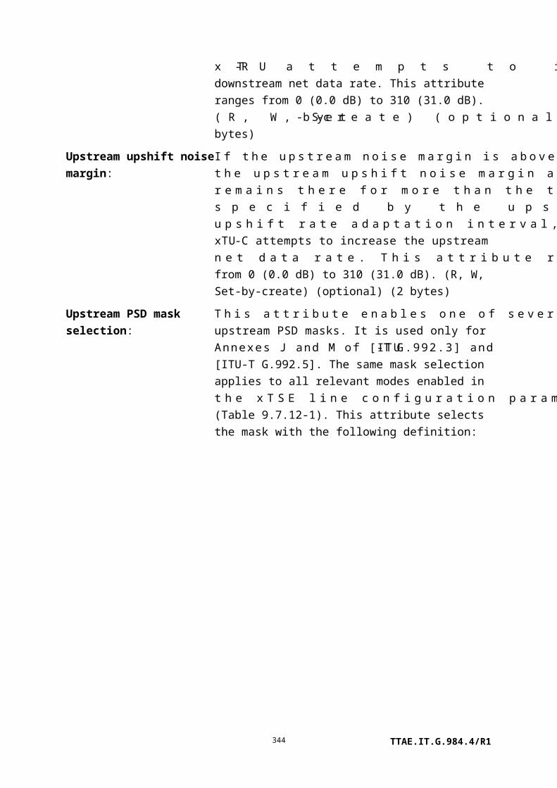
Errored seconds: This attribute counts one-second intervals with one or more FEBE anomalies summed over all transmitted bearer channels, or one or more LOS-FE defects, or one or more RDI defects, or one or more LPR-FE defects. (R) (mandatory) (2 bytes)
Severely errored seconds: This attribute counts severely errored seconds (SES-LFE). An SES is declared if, during a one-second interval, 18 or more FEBE anomalies were reported across the totality of bearer channels, or there were one or more far-end LOS defects, or one or more RDI defects, or one or more LPR-FE defects.
If the relevant Recommendation ([ITU-T G.992.3], [ITU-T G.992.5], [ITU-T G.993.2]) supports a one-second normalized CRC-8 anomaly counter increment, the one-second SES counter follows this value instead of counting FEBE anomalies directly.
If a CRC is applied for multiple bearer channels, then each related FEBE anomaly is counted only once for the whole set of related bearer channels.
(R) (mandatory) (2 bytes)
FEC seconds: This attribute counts seconds during which there was a forward error correction anomaly. (R) (mandatory) (2 bytes)
Unavailable seconds: This attribute counts one-second intervals during which the far-end xDSL line is unavailable.
The far-end xDSL line becomes unavailable at the onset of 10 contiguous SES-LFEs. The 10 SES-LFEs are included in unavailable time. Once unavailable, the far-end line becomes available at the onset of 10 contiguous seconds with no SES-LFEs. The 10 seconds with no SES-LFEs are excluded from unavailable time. Some attribute counts are inhibited during unavailability – see clause 7.2.7.13 of [ITU-T G.997.1].
(R) (mandatory) (2 bytes)
Actions
Create, delete, get, set
Get current data (optional)
Notifications
TTAE.IT.G.984.4/R1344

Threshold crossing alert
Number Threshold crossing alert Threshold value attribute # (Note)
0 Loss of frame seconds 1
1 Loss of signal seconds 2
2 Loss of power seconds 3
3 Errored seconds 4
4 Severely errored seconds 5
5 FEC seconds 6
6 Unavailable seconds 7
NOTE – This number associates the TCA with the specified threshold value attribute of the
threshold data 1 managed entity.
9.7.23 xDSL xTU-C channel performance monitoring history data
This managed entity collects performance monitoring data of an xTU-C to xTU-R channel as seen from the xTU-C. Instances of this managed entity are created and deleted by the OLT.
For a complete discussion of generic PM architecture, refer to clause I.1.9.
Relationships
An instance of this managed entity may be associated with each xDSL bearer channel.
Attributes
Managed entity id: This attribute uniquely identifies each instance of this managed entity. The two most significant bits of the first byte are the bearer channel ID. Excluding the first two bits of the first byte, the remaining part of the managed entity ID is identical to that of this ME's parent physical path termination point xDSL UNI part 1. (R, Set-by-create) (mandatory) (2 bytes)
Interval end time: This attribute identifies the most recently finished 15-minute interval. (R) (mandatory) (1 byte)
Threshold data 1/2 id: This attribute points to an instance of the threshold data 1 managed entity that contains PM threshold values. Since no threshold value attribute number exceeds 7, a threshold data 2 ME is optional. (R, W, Set-by-create) (mandatory) (2 bytes)
Corrected blocks: This attribute counts blocks received with errors that were corrected on this channel. (R) (mandatory) (4 bytes)
Uncorrected blocks: This attribute counts blocks received with uncorrectable errors on this channel. (R) (mandatory) (4 bytes)
TTAE.IT.G.984.4/R1345

Transmitted blocks: This attribute counts encoded blocks transmitted on this channel. (R) (mandatory) (4 bytes)
Received blocks: This attribute counts encoded blocks received on this channel. (R) (mandatory) (4 bytes)
Code violations: This attribute counts CRC-8 anomalies in the bearer channel. (R) (mandatory) (2 bytes)
Forward error corrections: This attribute counts FEC anomalies in the bearer channel. (R) (mandatory) (2 bytes)
Actions
Create, delete, get, set
Get current data (optional)
Notifications
Threshold crossing alert
Number Threshold crossing alert Threshold value attribute # (Note)
0 Corrected blocks 1
1 Uncorrected blocks 2
2 Code violations 3
3 Forward error corrections 4
NOTE – This number associates the TCA with the specified threshold value attribute of the
threshold data 1 managed entity.
9.7.24 xDSL xTU-R channel performance monitoring history data
This managed entity collects performance monitoring data of the xTU-C to xTU-R channel as seen from the xTU-R. Instances of this managed entity are created and deleted by the OLT.
For a complete discussion of generic PM architecture, refer to clause I.1.9.
Relationships
An instance of this managed entity may be associated with each xDSL bearer channel.
Attributes
Managed entity id: This attribute uniquely identifies each instance of this managed entity. The two most significant bits of the first byte are the bearer channel ID. Excluding the first two bits of the first byte, the remaining part of the managed entity ID is identical to that of this ME's parent physical path termination point xDSL UNI part 1. (R, Set-by-create) (mandatory) (2
TTAE.IT.G.984.4/R1346

bytes)
Interval end time: This attribute identifies the most recently finished 15-minute interval. (R) (mandatory) (1 byte)
Threshold data 1/2 id: This attribute points to an instance of the threshold data 1 managed entity that contains PM threshold values. Since no threshold value attribute number exceeds 7, a threshold data 2 ME is optional. (R, W, Set-by-create) (mandatory) (2 bytes)
Corrected blocks: This attribute counts blocks received with errors that were corrected on this channel. (R) (mandatory) (4 bytes)
Uncorrected blocks: This attribute counts blocks received with uncorrectable errors on this channel. (R) (mandatory) (4 bytes)
Transmitted blocks: This attribute counts encoded blocks transmitted on this channel. (R) (mandatory) (4 bytes)
Received blocks: This attribute counts encoded blocks received on this channel. (R) (mandatory) (4 bytes)
Code violations: This attribute counts FEBE anomalies reported in the downstream bearer channel. If the CRC is applied over multiple bearer channels, then each related FEBE anomaly increments each of the counters related to the individual bearer channels. (R) (mandatory) (2 bytes)
Forward error corrections: This attribute counts FFEC anomalies reported in the downstream bearer channel. If FEC is applied over multiple bearer channels, each related FFEC anomaly increments each of the counters related to the individual bearer channels. (R) (mandatory) (2 bytes)
Actions
Create, delete, get, set
Get current data (optional)
Notifications
Threshold crossing alert
Number Threshold crossing alert Threshold value attribute # (Note)
0 Corrected blocks 1
1 Uncorrected blocks 2
2 Code violations 3
TTAE.IT.G.984.4/R1347

3 Forward error corrections 4
NOTE – This number associates the TCA with the specified threshold value attribute of the
threshold data 1 managed entity.
9.7.25 TC adaptor performance monitoring history data xDSL
This managed entity collects performance monitoring data of an xTU-C to xTU-R ATM data path. Instances of this managed entity are created and deleted by the OLT.
For a complete discussion of generic PM architecture, refer to clause I.1.9.
Relationships
An instance of this managed entity may be associated with an instance of a physical path termination point xDSL UNI.
Attributes
Managed entity id: This attribute uniquely identifies each instance of this managed entity. Through an identical ID, this managed entity is implicitly linked to an instance of the physical path termination point xDSL UNI. (R) (mandatory) (2 bytes)
Interval end time: This attribute identifies the most recently finished 15-minute interval. (R) (mandatory) (1 byte)
Threshold data 1/2 id: This attribute points to an instance of the threshold data 1 managed entity that contains PM threshold values. Since no threshold value attribute number exceeds 7, a threshold data 2 ME is optional. (R, W, Set-by-create) (mandatory) (2 bytes)
Near-end HEC violation count:
This attribute counts near-end HEC anomalies in the ATM data path. (R) (mandatory) (2 bytes)
Near-end delineated total cell count (CD-P):
This attribute counts the total number of cells passed through the cell delineation and HEC function process operating on the ATM data path while in the SYNC state. (R) (mandatory) (4 bytes)
Near-end user total cell count:
This attribute counts the total number of cells in the ATM data path delivered at the V-C interface. (R) (mandatory) (4 bytes)
TTAE.IT.G.984.4/R1348

Near-end idle cell bit error count:
This attribute counts cells with bit errors in the ATM data path idle payload received at the near end. (R) (mandatory) (2 bytes)
Far-end HEC violation count:
This attribute counts far-end HEC anomalies in the ATM data path. (R) (mandatory) (2 bytes)
Far-end delineated total cell count:
This attribute counts the total number of cells passed through the cell delineation process and HEC function operating on the ATM data path while in the SYNC state. (R) (mandatory) (4 bytes)
Far-end user total cell count:
This attribute counts the total number of cells in the ATM data path delivered at the T-R interface. (R) (mandatory) (4 bytes)
Far-end idle cell bit error count:
This attribute counts cells with bit errors in the ATM data path idle payload received at the far end. (R) (mandatory) (2 bytes)
Actions
Create, delete, get, set
Get current data (optional)
Notifications
Threshold crossing alert
Number Threshold crossing alert Threshold value attribute # (Note)
0 Near end HEC violation 1
1 Near end idle cell bit error count 2
2 Far end HEC violation count 3
3 Far end idle cell bit error count 4
NOTE – This number associates the TCA with the specified threshold value attribute of the
threshold data 1 managed entity.
9.7.26 VDSL2 line configuration extensions 2
This managed entity extends the xDSL line configuration MEs with attributes that are unique to G.993.2 VDSL2. However, two of the attributes (FEXT and NEXT TXREFVNds) are used in [ITU-T G.992.3] and [ITU-T G.992.5]. The attributes of this ME are further defined in [ITU-T G.997.1]. An instance of this managed entity is created and deleted by the OLT.
TTAE.IT.G.984.4/R1349

Relationships
An instance of this managed entity may be associated with zero or more instances of the physical path termination point xDSL UNI part 1.
The overall xDSL line configuration profile is modelled in several parts, all of which are associated together through a common managed entity ID. (The client physical path termination point xDSL UNI part 1 has a single pointer, which refers to the entire set of line configuration parts.)
Attributes
Managed entity id: This attribute uniquely identifies each instance of this managed entity. All xDSL and VDSL2 line configuration profiles that pertain to a given physical path termination point xDSL must share a common managed entity id. (R, Set-by-create) (mandatory) (2 bytes)
SOS time downstream:
The SOS-TIME-ds attribute is used in the specification of receiver initiated SOS (see clause 13.4.3 of [ITU-T G.993.2]). If the attribute value is not zero, the standard SOS triggering criteria are enabled, and the value specifies the duration of the window used in the standard SOS triggering criteria in the downstream direction. The special value zero indicates that the standard SOS triggering criteria are disabled, i.e., vendor discretionary values may be used instead of the values configured in the MIB for the following parameters: SOS-NTONES-ds, SOS-CRC-ds, SOS-TIME-ds. The valid range of non-zero values is from 1..255, specifying 64 to 16320 ms in steps of 64 ms. (R, W, Set-by-create) (optional) (1 byte)
SOS time upstream: The SOS-TIME-us attribute is used in the specification of receiver initiated SOS (see clause 13.4.3 of [ITU-T G.993.2]). If the attribute value is not zero, the standard SOS triggering criteria are enabled, and the value specifies the duration of the window used in the standard SOS triggering criteria in the upstream direction. The special value zero indicates that the standard SOS triggering criteria are disabled, i.e., vendor discretionary values may be used instead of the values configured in the MIB for the following parameters: SOS-NTONES-us, SOS-CRC-us, SOS-TIME-us. The valid range of non-zero values is from 1..255, specifying 64 to 16320 ms in steps of 64 ms. (R, W, Set-by-create) (optional) (1 byte)
TTAE.IT.G.984.4/R1350

SOS degraded tones threshold downstream:
The SOS-NTONES-ds attribute is the minimum percentage of tones in the downstream medley set that must be degraded in order to arm the first sub-condition of the standard SOS triggering criteria in the downstream direction. The valid range of values is from 1 to 100% in steps of 1. Use of the special value 0 is described in clause 13.4.3.2 of [ITU-T G.993.2]. (R, W, Set-by-create) (optional) (1 byte)
SOS degraded tones threshold upstream:
The SOS-NTONES-us attribute is the minimum percentage of tones in the upstream medley set that must be degraded in order to arm the first sub-condition of the standard SOS triggering criteria in the upstream direction. The valid range of values is from 1 to 100% in steps of 1. Use of the special value 0 is described in clause 13.4.3.2 of [ITU-T G.993.2]. (R, W, Set-by-create) (optional) (1 byte)
SOS CRC threshold downstream:
The SOS-CRC-ds attribute is the minimum number of normalized CRC anomalies received in SOS-TIME-ds seconds in order to arm the second sub-condition of the standard SOS triggering criteria (see clause 13.4.3.2 of [ITU-T G.993.2]) in the downstream direction. The valid range of SOS-CRC values is 0.02 to (216–1) * 0.02, in steps of 0.02. (R, W, Set-by-create) (optional) (2 bytes)
SOS CRC threshold upstream:
The SOS-CRC-us attribute is the minimum number of normalized CRC anomalies received in SOS-TIME-us seconds in order to arm the second sub-condition of the standard SOS triggering criteria (see clause 13.4.3.2 of [ITU-T G.993.2]) in the upstream direction. The valid range of SOS-CRC values is 0.02 to (216–1) * 0.02, in steps of 0.02. (R, W, Set-by-create) (optional) (2 bytes)
MAX SOS downstream:
The MAX-SOS-ds attribute is used in deactivation. If the number of successful SOS procedures in the downstream direction performed within a 120-second interval exceeds MAX-SOS-ds, the modem goes to state L3. See clause 12.1.4 of [ITU-T G.993.2] for details. The valid range of values is 1 to 15, with special value 0 as described in clause 12.1 of [ITU-T G.993.2]. (R, W, Set-by-create) (optional) (1 byte)
MAX SOS upstream: The MAX-SOS-us attribute is used in deactivation. If the number of successful SOS procedures in the upstream direction performed within a 120-second interval exceeds MAX-SOS-us, the modem goes to state L3. See clause 12.1.4 of [ITU-T G.993.2] for details. The valid range of values is 1 to 15, with special value 0 as
TTAE.IT.G.984.4/R1351

described in clause 12.1 of [ITU-T G.993.2]. (R, W, Set-by-create) (optional) (1 byte)
SNR max offset downstream:
The SNRMOFFSET-ROC-ds attribute is the SNR margin offset for the robust operations channel ROC in the downstream direction. The attribute is used in the specification of the channel initialization policy (see clause 12.3.7.1 of [ITU-T G.993.2]). The valid range of SNR margin offset values is from 0..31 dB in 0.1 dB steps. (R, W, Set-by-create) (optional) (2 bytes)
SNR max offset upstream:
The SNRMOFFSET-ROC-us attribute is the SNR margin offset for the robust operations channel ROC in the upstream direction. The attribute is used in the specification of the channel initialization policy (see clause 12.3.7.1 of [ITU-T G.993.2]). The valid range of SNR margin offset values is from 0..31 dB in 0.1 dB steps. (R, W, Set-by-create) (optional) (2 bytes)
ROC minimum impulse noise protection downstream:
The INPMIN-ROC-ds attribute specifies the minimum impulse noise protection to apply on the robust operations channel ROC in the downstream direction. The minimum impulse noise protection is an integer ranging from 0 to 16. (R, W, Set-by-create) (optional) (1 byte)
ROC minimum impulse noise protection upstream:
The INPMIN-ROC-us attribute specifies the minimum impulse noise protection to apply on the robust operations channel ROC in the upstream direction. The minimum impulse noise protection is an integer ranging from 0 to 16. (R, W, Set-by-create) (optional) (1 byte)
TTAE.IT.G.984.4/R1352

FEXT downstream transmitter referred virtual noise table:
The FEXT TXREFVNds attribute is the downstream transmitter referred virtual noise specified for FEXTR duration in G.992.3 (ADSL2) Annex C and G.992.5 (ADSL2plus) Annex C. The syntax of this attribute is the same as that of the TXREFVNds table attribute of the VDSL2 line configuration extensions managed entity. (R, W) (mandatory for G.992.3 Annex C and G.992.5 Annex C) (3N bytes, where N is the number of breakpoints)
NEXT downstream transmitter referred virtual noise table:
The NEXT TXREFVNds attribute is the downstream transmitter referred virtual noise specified for NEXTR duration in G.992.3 (ADSL2) Annex C and G.992.5 (ADSL2plus) Annex C. The syntax of this attribute is the same as that of the TXREFVNds table attribute of the VDSL2 line configuration extensions managed entity. (R, W) (mandatory for G.992.3 Annex C and G.992.5 Annex C) (3N bytes, where N is the number of breakpoints)
Actions
Create, delete, get, get next, set, Set table (optional)
Notifications
None.
9.7.27 xDSL impulse noise monitor performance monitoring history data
This managed entity collects performance monitoring data from the impulse noise monitor function at both near and far ends. Instances of this managed entity are created and deleted by the OLT. Note that [ITU-T G.997.1] only requires current and previous 15-minute interval storage; a longer view of this PM is not expected at 15-minute granularity.
For a complete discussion of generic PM architecture, refer to clause I.1.9.
Relationships
An instance of this managed entity may be associated with a physical path termination point xDSL UNI. This managed entity is meaningful only for G.993.2 VDSL2, [ITU-T G.992.3] and [ITU-T G.992.5].
Attributes
Managed entity id: This attribute uniquely identifies each instance of this managed entity. The managed entity ID is identical to that of this ME's parent physical path termination point xDSL UNI part 1. (R, Set-by-create) (mandatory) (2 bytes)
TTAE.IT.G.984.4/R1353

Interval end time: This attribute identifies the most recently finished 15-minute interval. (R) (mandatory) (1 byte)
Threshold data 1/2 id: No thresholds are defined for this managed entity. For uniformity with other PM, the attribute is retained and shown as mandatory, but it should be set to a null pointer. (R, W, Set-by-create) (mandatory) (2 bytes)
INM INPEQ histogram table:
INMINPEQ1..17-L is a count of the near-end INMAINPEQi anomalies occurring on the line during the accumulation period. This parameter is subject to inhibiting – see clause 7.2.7.13 of [ITU-T G.997.1]. (R) (optional) (2 bytes 17 entries = 34 bytes)
INM total measurement:
INMME-L is a count of the near-end INMAME anomalies occurring on the line during the accumulation period. This parameter is subject to inhibiting – see clause 7.2.7.13 of [ITU-T G.997.1]. (R) (optional) (2 bytes)
INM IAT histogram: INMIAT0..7-L is a count of the near-end INMAIATi anomalies occurring on the line during the accumulation period. This parameter is subject to inhibiting – see clause 7.2.7.13 of [ITU-T G.997.1]. (R) (optional) (2 bytes 8 entries = 16 bytes)
INM INPEQ histogram LFE table:
INMINPEQ1..17-LFE is a count of the far-end INMAINPEQi anomalies occurring on the line during the accumulation period. This parameter is subject to inhibiting – see clause 7.2.7.13 of [ITU-T G.997.1]. (R) (optional) (2 bytes 17 entries = 34 bytes)
INM total measurement LFE:
INMME-LFE is a count of the far-end INMAME anomalies occurring on the line during the accumulation period. This parameter is subject to inhibiting – see clause 7.2.7.13 of [ITU-T G.997.1]. (R) (optional) (2 bytes)
INM IAT histogram LFE:
INMIAT0..7-LFE is a count of the far-end INMAIATi anomalies occurring on the line during the accumulation period. This parameter is subject to inhibiting – see clause 7.2.7.13 of [ITU-T G.997.1]. (R) (optional) (2 bytes 8 entries = 16 bytes)
Actions
Create, delete, get, get next, set
Get current data (optional)
Notifications
None.
TTAE.IT.G.984.4/R1354

9.7.28 xDSL line inventory and status data part 5
This managed entity extends the attributes defined in the xDSL line inventory and status data parts 1..4. This ME reports FEXT and NEXT attributes, and pertains to G.992.3 (ADSL2) Annex C and G.992.5 (ADSL2plus) Annex C.
Relationships
This is one of the status data MEs pointed to by a physical path termination point xDSL managed entity. The ONT automatically creates or deletes an instance of this managed entity upon creation or deletion of a physical path termination point xDSL that supports these attributes.
Attributes
Managed entity id: This attribute uniquely identifies each instance of this managed entity. Through an identical id, this managed entity is implicitly linked to an instance of the physical path termination point xDSL managed entity. (R) (mandatory) (2 bytes)
FEXT downstream signal-to-noise ratio margin:
The FEXT SNRMds attribute is the downstream signal-to-noise ratio margin measured during FEXTR duration at the ATU-R. The attribute value ranges from 0 (–64.0 dB) to 1270 (+63.0 dB). The special value 0xFFFF indicates that the attribute is out of range. (R) (mandatory) (2 bytes)
TTAE.IT.G.984.4/R1355

NEXT downstream signal-to-noise ratio margin:
The NEXT SNRMds attribute is the downstream signal-to-noise ratio margin measured during NEXTR duration at the ATU-R. The attribute value ranges from 0 (–64.0 dB) to 1270 (+63.0 dB). The special value 0xFFFF indicates that the attribute is out of range. (R) (mandatory) (2 bytes)
FEXT upstream signal-to-noise ratio margin:
The FEXT SNRMus attribute is the upstream signal-to-noise ratio margin (see clause 7.5.1.16 of [ITU-T G.997.1]) measured during FEXTC duration at the ATU-C. The attribute value ranges from 0 (–64.0 dB) to 1270 (+63.0 dB). The special value 0xFFFF indicates that the attribute is out of range. (R) (mandatory) (2 bytes)
NEXT upstream signal-to-noise ratio margin:
The NEXT SNRMus attribute is the upstream signal-to-noise ratio margin (see clause 7.5.1.16 of [ITU-T G.997.1]) measured during NEXTC duration at the ATU-C. The attribute value ranges from 0 (–64.0 dB) to 1270 (+63.0 dB). The special value 0xFFFF indicates that the attribute is out of range. (R) (mandatory) (2 bytes)
FEXT downstream maximum attainable data rate:
The FEXT ATTNDRds attribute is the maximum downstream net data rate calculated from FEXT downstream SNR(f) (see clause 7.5.1.19.1 of [ITU-T G.997.1]). The rate is coded in bit/s. (R) (mandatory) (4 bytes)
NEXT downstream maximum attainable data rate:
The NEXT ATTNDRds attribute is the maximum downstream net data rate calculated from NEXT downstream SNR(f) (see clause 7.5.1.19.2 of [ITU-T G.997.1]). The rate is coded in bit/s. (R) (mandatory) (4 bytes)
FEXT upstream maximum attainable data rate:
The FEXT ATTNDRus attribute is the maximum upstream net data rate calculated from FEXT upstream SNR(f) (see clause 7.5.1.20.1 of [ITU-T G.997.1]). The rate is coded in bit/s. (R) (mandatory) (4 bytes)
NEXT upstream maximum attainable data rate:
The NEXT ATTNDRus attribute is the maximum upstream net data rate calculated from NEXT upstream SNR(f) (see clause 7.5.1.20.2 of [ITU-T G.997.1]). The rate is coded in bit/s. (R) (mandatory) (4 bytes)
FEXT downstream actual power spectral density:
The FEXT ACTPSDds attribute is the average downstream transmit PSD over the used subcarriers (see clause 7.5.1.21 of [ITU-T G.997.1]) calculated from the REFPSDds and RMSGIds for FEXTR duration. The attribute value ranges from 0 (–90.0
TTAE.IT.G.984.4/R1356

dBm/Hz) to 900 (0.0 dBm/Hz). The special value 0xFFFF indicates that the parameter is out of range. (R) (mandatory) (2 bytes)
NEXT downstream actual power spectral density:
The NEXT ACTPSDds attribute is the average downstream transmit PSD over the used subcarriers (see clause 7.5.1.21 of [ITU-T G.997.1]) calculated from the REFPSDds and RMSGIds for NEXTR duration. The attribute value ranges from 0 (–90.0 dBm/Hz) to 900 (0.0 dBm/Hz). The special value 0xFFFF indicates that the parameter is out of range. (R) (mandatory) (2 bytes)
FEXT upstream actual power spectral density:
The FEXT ACTPSDus attribute is the average upstream transmit PSD over the used subcarriers (see clause 7.5.1.22 of [ITU-T G.997.1]) calculated from the REFPSDus and RMSGIus for FEXTC duration. The attribute value ranges from 0 (–90.0 dBm/Hz) to 900 (0.0 dBm/Hz). The special value 0xFFFF indicates that the parameter is out of range. (R) (mandatory) (2 bytes)
TTAE.IT.G.984.4/R1357

NEXT upstream actual power spectral density:
The NEXT ACTPSDus attribute is the average upstream transmit PSD over the used subcarriers (see clause 7.5.1.22 of [ITU-T G.997.1]) calculated from the REFPSDus and RMSGIus for NEXTC duration. The attribute value ranges from 0 (–90.0 dBm/Hz) to 900 (0.0 dBm/Hz). The special value 0xFFFF indicates that the parameter is out of range. (R) (mandatory) (2 bytes)
FEXT downstream actual aggregate transmit power:
The FEXT ACTATPds attribute is the total amount of transmit power (see clause 7.5.1.24 of [ITU-T G.997.1]) calculated from PSDds measured during FEXTR duration at the ATU-R. The attribute value ranges from 0 (–31.0 dBm ) to 620 (+31.0 dBm). The special value 0xFFFF indicates that the parameter is out of range. (R) (mandatory) (2 bytes)
NEXT downstream actual aggregate transmit power:
The NEXT ACTATPds attribute is the total amount of transmit power (see clause 7.5.1.24 of [ITU-T G.997.1]) calculated from PSDds measured during NEXTR duration at the ATU-R. The attribute value ranges from 0 (–31.0 dBm ) to 620 (+31.0 dBm). The special value 0xFFFF indicates that the parameter is out of range. (R) (mandatory) (2 bytes)
FEXT upstream actual aggregate transmit power:
The FEXT ACTATPus attribute is the total transmit power (see clause 7.5.1.25 of [ITU-T G.997.1]) calculated from PSDus measured during FEXTC duration at the ATU-C. The attribute value ranges from 0 (–31.0 dBm ) to 620 (+31.0 dBm). The special value 0xFFFF indicates that the parameter is out of range. (R) (mandatory) (2 bytes)
NEXT upstream actual aggregate transmit power:
The NEXT ACTATPus attribute is the total transmit power (see clause 7.5.1.25 of [ITU-T G.997.1]) calculated from PSDus measured during NEXTC duration at the ATU-C. The attribute value ranges from 0 (–31.0 dBm ) to 620 (+31.0 dBm). The special value 0xFFFF indicates that the parameter is out of range. (R) (mandatory) (2 bytes)
Actions
Get, get next
Notifications
None.
TTAE.IT.G.984.4/R1358

9.7.29 xDSL line inventory and status data part 6
This managed entity extends the attributes defined in the xDSL line inventory and status data parts 1..4. This ME reports FEXT and NEXT attributes, and pertains to G.992.3 (ADSL2) Annex C and G.992.5 (ADSL2plus) Annex C.
Relationships
This is one of the status data MEs pointed to by a physical path termination point xDSL managed entity. The ONT automatically creates or deletes an instance of this managed entity upon creation or deletion of a physical path termination point xDSL that supports these attributes.
Attributes
Managed entity id: This attribute uniquely identifies each instance of this managed entity. Through an identical id, this managed entity is implicitly linked to an instance of the physical path termination point xDSL managed entity. (R) (mandatory) (2 bytes)
FEXT downstreamquiet line noise PSD measurement time:
The FEXT QLNMTds attribute is the number of symbols used to measure FEXT downstream QLN(f) (see clause 7.5.1.27.3.1 of [ITU-T G.997.1]). (R) (mandatory) (2 bytes)
NEXT downstream quiet line noise PSD measurement time:
The NEXT QLNMTds attribute is the number of symbols used to measure NEXT downstream QLN(f) (see clause 7.5.1.27.3.2 of [ITU-T G.997.1]). (R) (mandatory) (2 bytes)
FEXT downstreamQLN(f) table:
The FEXT QLNpsds attribute is the downstream QLN(f) (see clause 7.5.1.27.3 of [ITU-T G.997.1]) measured during FEXTR
duration at the ATU-R. The attribute syntax is the same as that of the downstream QLNpsds table attribute of the xDSL line inventory and status data part 3 managed entity. (R) (mandatory) (N bytes, where N is the number of subcarrier groups)
NEXT downstream QLN(f) table:
The NEXT QLNpsds attribute is the downstream QLN(f) (see clause 7.5.1.27.3 of [ITU-T G.997.1]) measured during NEXTR
duration at the ATU-R. The attribute syntax is the same as that of the downstream QLNpsds table attribute of the xDSL line inventory and status data part 3 managed entity. (R) (mandatory) (N bytes, where N is the number of subcarrier groups)
FEXT upstream quiet line noise PSD measurement time:
The FEXT QLNMTus attribute is the number of symbols used to measure FEXT upstream QLN(f) (see clause 7.5.1.27.6.1 of [ITU-T G.997.1]). (R) (mandatory) (2 bytes)
NEXT upstream quiet The NEXT QLNMTus attribute is the number of symbols used to
TTAE.IT.G.984.4/R1359

line noise PSD measurement time:
measure NEXT upstream QLN(f) (see clause 7.5.1.27.6.2 of [ITU-T G.997.1]). (R) (mandatory) (2 bytes)
FEXT upstream QLN(f) table:
The FEXT QLNpsus attribute is the upstream QLN(f) (see clause 7.5.1.27.6 of [ITU-T G.997.1]) measured during FEXTC
duration at the ATU-C. The attribute syntax is the same as that of the downstream QLNpsds table attribute of the xDSL line inventory and status data part 3 managed entity. (R) (mandatory) (N bytes, where N is the number of subcarrier groups)
NEXT upstream QLN(f) table:
The NEXT QLNpsus attribute is the upstream QLN(f) (see clause 7.5.1.27.6 of [ITU-T G.997.1]) measured during NEXTC
duration at the ATU-C. The attribute syntax is the same as that of the downstream QLNpsds table attribute of the xDSL line inventory and status data part 3 managed entity. (R) (mandatory) (N bytes, where N is the number of subcarrier groups)
FEXT downstreamSNR measurement time:
The FEXT SNRMTds attribute is the number of symbols used to measure FEXT downstream SNR(f) values (see clause 7.5.1.28.1.1 of [ITU-T G.997.1]). Its value corresponds to the value specified in the Recommendation (e.g., the number of symbols in a 1-second interval for [ITU-T G.992.3]). (R) (mandatory) (2 bytes)
NEXT downstream SNR measurement time:
The NEXT SNRMTds attribute is the number of symbols used to measure NEXT downstream SNR(f) values (see clause 7.5.1.28.1.2 of [ITU-T G.997.1]). Its value corresponds to the value specified in the Recommendation (e.g., the number of symbols in a 1-second interval for [ITU-T G.992.3]). (R) (mandatory) (2 bytes)
TTAE.IT.G.984.4/R1360

FEXT downstreamSNR(f) table:
The FEXT SNRpsds attribute is the downstream SNR(f) (see clause 7.5.1.28.3 of [ITU-T G.997.1]) measured during FEXTR
duration at the ATU-R. The attribute is represented in the same way as the SNRpsds table attribute of the xDSL line inventory and status data part 3 managed entity. (R) (mandatory) (N bytes, where N is the number of subcarrier groups)
NEXT downstreamSNR(f) table:
The NEXT SNRpsds attribute is the downstream SNR(f) (see clause 7.5.1.28.3 of [ITU-T G.997.1]) measured during NEXTR
duration at the ATU-R. The attribute is represented in the same way as the SNRpsds table attribute of the xDSL line inventory and status data part 3 managed entity. (R) (mandatory) (N bytes, where N is the number of subcarrier groups)
FEXT upstream SNR measurement time:
The FEXT SNRMTus attribute is the number of symbols used to measure FEXT upstream SNR(f) values (see clause 7.5.1.28.4.1 of [ITU-T G.997.1]). Its value corresponds to the value specified in the Recommendation (e.g., the number of symbols in a 1-second interval for [ITU-T G.992.3]). (R) (mandatory) (2 bytes)
NEXT upstream SNR measurement time:
The NEXT SNRMTus attribute is the number of symbols used to measure NEXT upstream SNR(f) values (see clause 7.5.1.28.4.2 of [ITU-T G.997.1]). Its value corresponds to the value specified in the Recommendation (e.g., the number of symbols in a 1-second interval for [ITU-T G.992.3]). (R) (mandatory) (2 bytes)
FEXT upstream SNR(f) table:
The FEXT SNRpsus attribute is the upstream SNR(f) (see clause 7.5.1.28.6 of [ITU-T G.997.1]) measured during FEXTC
duration at the ATU-C. The attribute is represented in the same way as the SNRpsds table attribute of the xDSL line inventory and status data part 3 managed entity. (R) (mandatory) (N bytes, where N is the number of subcarrier groups)
NEXT upstream SNR(f) table:
The NEXT SNRpsus attribute is the upstream SNR(f) (see clause 7.5.1.28.6 of [ITU-T G.997.1]) measured during NEXTC
duration at the ATU-C. The attribute is represented in the same way as the SNRpsds table attribute of the xDSL line inventory and status data part 3 managed entity. (R) (mandatory) (N bytes, where N is the number of subcarrier groups)
Actions
Get, get next
TTAE.IT.G.984.4/R1361

Notifications
None.
9.7.30 xDSL line inventory and status data part 7
This managed entity extends the attributes defined in the xDSL line inventory and status data parts 1..4. This ME reports FEXT and NEXT attributes, and pertains to G.992.3 (ADSL2) Annex C and G.992.5 (ADSL2plus) Annex C.
Relationships
This is one of the status data MEs pointed to by a physical path termination point xDSL managed entity. The ONT automatically creates or deletes an instance of this managed entity upon creation or deletion of a physical path termination point xDSL that supports these attributes.
Attributes
Managed entity id: This attribute uniquely identifies each instance of this managed entity. Through an identical id, this managed entity is implicitly linked to an instance of the physical path termination point xDSL managed entity. (R) (mandatory) (2 bytes)
FEXT downstream bits allocation table:
The FEXT BITSpsds attribute is the downstream bits allocation table per subcarrier (see clause 7.5.1.29.1 of [ITU-T G.997.1]) used during FEXTR duration. The syntax of this attribute is the same as that of the BITSpsds table attribute of the xDSL line inventory and status data part 3 managed entity. (R) (mandatory) (N bytes, where N is the number of subcarrier groups)
NEXT downstream bits allocation table:
The NEXT BITSpsds attribute is the downstream bits allocation table per subcarrier (see clause 7.5.1.29.1 of [ITU-T G.997.1]) used during NEXTR duration. The syntax of this attribute is the same as that of the BITSpsds table attribute of the xDSL line inventory and status data part 3 managed entity. (R) (mandatory) (N bytes, where N is the number of subcarrier groups)
FEXT upstream bits allocation table:
The FEXT BITSpsus attribute is the upstream bits allocation table per subcarrier (see clause 7.5.1.29.2 of [ITU-T G.997.1]) used during FEXTC duration. The syntax of this attribute is the same as that of the BITSpsds table attribute of the xDSL line inventory and status data part 3 managed entity. (R) (mandatory) (N bytes, where N is the number of subcarriers)
NEXT upstream bits allocation table:
The NEXT BITSpsus attribute is the upstream bits allocation table per subcarrier (see clause 7.5.1.29.2 of [ITU-T G.997.1]) used
TTAE.IT.G.984.4/R1362

during NEXTC duration. The syntax of this attribute is the same as that of the BITSpsds table attribute of the xDSL line inventory and status data part 3 managed entity. (R) (mandatory) (N bytes, where N is the number of subcarriers)
FEXT downstream gains allocation table:
The FEXT GAINSpsds attribute is the downstream gains allocation table per subcarrier (see clause 7.5.1.29.3 of [ITU-T G.997.1]) used during FEXTR duration. The syntax of this attribute is the same as that of the GAINSpsds table attribute of the xDSL line inventory and status data part 3 managed entity. (R) (mandatory) (2N bytes, where N is the number of subcarriers)
NEXT downstream gains allocation table:
The NEXT GAINSpsds attribute is the downstream gains allocation table per subcarrier (see clause 7.5.1.29.3 of [ITU-T G.997.1]) used during NEXTR duration. The syntax of this attribute is the same as that of the GAINSpsds table attribute of the xDSL line inventory and status data part 3 managed entity. (R) (mandatory) (2N bytes, where N is the number of subcarriers)
FEXT upstream gains allocation table:
The FEXT GAINSpsus attribute is the upstream gains allocation table per subcarrier (see clause 7.5.1.29.4 of [ITU-T G.997.1]) used during FEXTC duration. The syntax of this attribute is the same as that of the GAINSpsds table attribute of the xDSL line inventory and status data part 3 managed entity. (R) (mandatory) (2N bytes, where N is the number of subcarriers)
NEXT upstream gains allocation table:
The NEXT GAINSpsus attribute is the upstream gains allocation table per subcarrier (see clause 7.5.1.29.4 of [ITU-T G.997.1]) used during NEXTC duration. The syntax of this attribute is the same as that of the GAINSpsds table attribute of the xDSL line inventory and status data part 3 managed entity. (R) (mandatory) (2N bytes, where N is the number of subcarriers)
FEXT downstream transmit spectrum shaping table:
The FEXT TSSpsds attribute is the downstream transmit spectrum shaping parameter set per subcarrier (see clause 7.5.1.29.5 of [ITU-T G.997.1]) used during FEXTR duration. The syntax of this attribute is the same as that of the TSSpsds table attribute of the xDSL line inventory and status data part 3 managed entity. (R) (mandatory) (3N bytes, where N is the number of breakpoints)
NEXT downstream transmit spectrum shaping table:
The NEXT TSSpsds attribute is the downstream transmit spectrum shaping parameter set per subcarrier (see clause 7.5.1.29.5 of [ITU-T G.997.1]) used during NEXTR
TTAE.IT.G.984.4/R1363

duration. The syntax of this attribute is the same as that of the TSSpsds table attribute of the xDSL line inventory and status data part 3 managed entity. (R) (mandatory) (3N bytes, where N is the number of breakpoints)
FEXT upstream transmit spectrum shaping table:
The FEXT TSSpsus attribute is the upstream transmit spectrum shaping parameter set per subcarrier (see clause 7.5.1.29.6 of [ITU-T G.997.1]) used during FEXTC duration. The syntax of this attribute is the same as that of the TSSpsus table attribute of the xDSL line inventory and status data part 4 managed entity. (R) (mandatory) (3N bytes, where N is the number of breakpoints)
NEXT upstream transmit spectrum shaping table:
The NEXT TSSpsus attribute is the upstream transmit spectrum shaping parameter set per subcarrier (see clause 7.5.1.29.6 of [ITU-T G.997.1]) used during NEXTC duration. The syntax of this attribute is the same as that of the TSSpsus table attribute of the xDSL line inventory and status data part 4 managed entity. (R) (mandatory) (3N bytes, where N is the number of breakpoints)
Actions
Get, get next
Notifications
None.
TTAE.IT.G.984.4/R1364

9.8 TDM services
This clause defines managed entities associated with CES UNIs, as shown in Figure 9.8-1.
Figure 9.8-1 – Managed entities associated with CES UNIs
9.8.1 Physical path termination point CES UNI
This managed entity represents the point at a CES UNI in the ONT where the physical path terminates and physical level functions are performed.
The ONT automatically creates an instance of this managed entity per port:
• When the ONT has CES ports built into its factory configuration.
• When a cardholder is provisioned to expect a circuit pack of CES type.
• When a cardholder provisioned for plug-and-play is equipped with a circuit pack of CES type. Note that the installation of a plug-and-play card may indicate the presence of CES ports via equipment ID as well as its type, and indeed may cause the ONT to instantiate a port mapping package that specifies CES ports.
The ONT automatically deletes instances of this managed entity when a cardholder is neither provisioned to expect a CES circuit pack, nor is it equipped with a CES circuit pack.
Relationships
An instance of this managed entity is associated with each real or preprovisioned CES port. It can be linked from a pseudowire or a TU TP, or a logical N × 64 kbit/s CTP.
Attributes
TTAE.IT.G.984.4/R1365
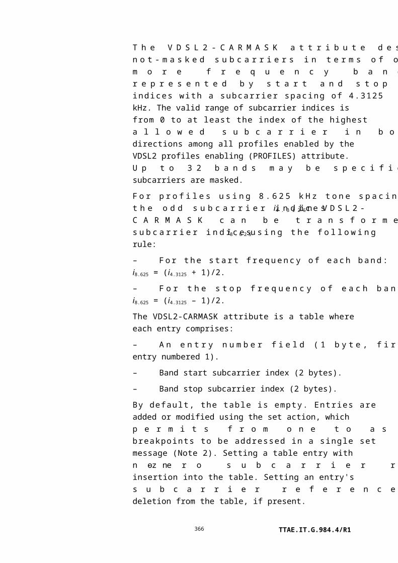
Managed entity id: This attribute uniquely identifies each instance of this managed entity. This two-byte number indicates the physical position of the UNI. The first byte is the slot id (defined in clause 9.1.5). The second byte is the port ID, with range 1..255. (R) (mandatory) (2 bytes)
Expected type: The following coding is used for this attribute:
0 Autosense.1 to 254 One of the values from Table 9.1.5-1 that is
compatible with a CES circuit pack.
Upon ME instantiation, the ONT sets this attribute to 0. (R, W) (mandatory) (1 byte)
Sensed type: If the value of expected type is not 0, then the value of sensed type equals the value of expected type. If expected type = 0, then the value of sensed type is one of the compatible values from Table 9.1.5-1. Upon ME instantiation, the ONT sets this attribute to 0 or to the value that reflects the physically present equipment. (R) (mandatory if the ONT supports circuit packs with configurable interface types, e.g., C1.5/2/6.3) (1 byte)
CES loopback configuration:
This attribute specifies and reports the loopback configuration of the physical interface.
0 No loopback.1 Payload loopback.2 Line loopback.3 OpS-directed loopback 1 (loopback from/to PON side).4 OpS-directed loopback 2 (loopback from/to CES UNI
side).5 OpS-directed loopback 3 (loopback of both PON side
and CES UNI side).6 Manual button-directed loopback (read only).7 Network-side code inband-directed loopback (read only).8 SmartJack-directed loopback (read only).9 Network-side code inband-directed loopback (armed;
read only).
Upon ME instantiation, the ONT sets this attribute to 0. (R, W) (mandatory) (1 byte)
TTAE.IT.G.984.4/R1366

Figure 9.8.1-1 – CES loopback configuration
Administrative state: This attribute locks (1) and unlocks (0) the functions performed by this managed entity. When the administrative state is set to lock, all user functions of this UNI are blocked, and alarms, TCAs and AVCs for this managed entity and all dependent managed entities are no longer generated. Selection of a default value for this attribute is outside the scope of this Recommendation. (R, W) (mandatory) (1 byte)
Operational state: This attribute indicates whether or not the managed entity is capable of performing its function. Valid values are enabled (0) and disabled (1). (R) (optional) (1 byte)
Framing: This attribute specifies the framing structure.
These code points are for use with DS1 services. Code point 2 may also be used for unframed E1 service.
0 Extended superframe1 Superframe2 Unframed3 G.704
NOTE – [ITU-T G.704] describes both SF and ESF framing for
DS1 signals. This code point is retained for backward
compatibility, but its meaning is undefined.
4 JT-G.704
The following code points are for use with E1 services.
5 Basic framing: clause 2.3.2 of [ITU-T G.704]6 Basic framing with CRC-4: clause 2.3.3 of [ITU-T G.704]7 Basic framing with TS16 multiframe8 Basic framing with CRC-4 and TS16 multiframe
Upon ME instantiation, the ONT sets this attribute to a value
TTAE.IT.G.984.4/R1367

that reflects the vendor's default. (R, W) (optional) (1 byte)
Encoding: This attribute specifies the line coding scheme. Valid values are:
0 B8ZS.1 AMI.2 HDB3.3 B3ZS.
Upon ME instantiation, the ONT sets this attribute to 0. (R, W) (mandatory for DS1 and DS3 interfaces) (1 byte)
Line length: This attribute specifies the length of the twisted pair cable from a DS1 physical UNI to the DSX-1 cross-connect point or the length of coaxial cable from a DS3 physical UNI to the DSX-3 cross-connect point. Valid values are given in Table 9.8.1-1. Upon ME instantiation for a DS1 interface, the ONT assigns the value 0 for non-power feed type DS1 and the value 6 for power feed type DS1. Upon ME instantiation for a DS3 interface, the ONT sets this attribute to 0x0F. (R, W) (optional) (1 byte)
DS1 mode: This attribute specifies the mode of a DS1. Valid values are as shown:
Value Mode Connect Line length Power Loopback
0 #1 DS1 CPE Short haul No power feed Smart jack
1 #2 DS1 CPE Long haul No power feed Smart jack
2 #3 DS1 NIU CPE Long haul No power feed Intelligent office repeater.
Transparent to FDL
3 #4 DS1 NIU CPE Long haul With power feed Intelligent office repeater.
Transparent to FDL
In the event of conflicting values between this attribute and the (also optional) line length attribute, the line length attribute is taken to be valid. This permits the separation of LBO and power settings from smart jack and FDL behaviour. Upon ME instantiation, the ONT sets this attribute to 0. (R, W) (optional) (1 byte)
ARC: See clause I.1.8. (R, W) (optional) (1 byte)
TTAE.IT.G.984.4/R1368

ARC interval: See clause I.1.8. (R, W) (optional) (1 byte)Line type: This attribute specifies the line type used in a DS3 or E3
application, or when the sensed type of the PPTP is configurable. Valid values are:0 Other1 ds3 m232 ds3 syntran3 ds3 Cbit parity4 ds3 clear channel5 e3 framed6 e3 plcp7 DS18 E19 J1(R, W) (mandatory for DS3, E3 and multi-configuration interfaces, not applicable to other interfaces) (1 byte)
Actions
Get, set
Notifications
Attribute value change
Number Attribute value change Description
1 N/A
2 Sensed type Sensed circuit pack type (value from Table 9.1.5-1)
3 CES loopback config Loopback configuration of physical interface
4 N/A
5 Op state Operational state
6..9 N/A
10 ARC ARC timer expiration
11..12 N/A
13..16 Reserved
Alarm: These alarms should be declared and cleared according to criteria defined separately in existing TDM standards.
Number Alarm Description
0 TF Transmitter failure
1 LOS Loss of signal
TTAE.IT.G.984.4/R1369

Number Alarm Description
2 LOF Loss of frame
3 OOF Out of frame
4 RAI Remote alarm indication
5 1.5 M BAIS 1.544 Mbit/s back alarm indication signal
6 R-INH Receive alarm inhibit
7 6M REC 6.312 Mbit/s receive alarm
8 6M SEND 6.312 Mbit/s send alarm
9 6M ERR 6.312 Mbit/s block error
10 6M BERR 6.312 Mbit/s back error
11 34M REC 34.368 Mbit/s receive alarm
12 34M AIS 34.368 Mbit/s alarm indication signal
13 2M REC 2.048 Mbit/s receive alarm
14 2M AIS 2.048 Mbit/s alarm indication signal
15 1.5M REC 1.544 Mbit/s receive alarm
16 1.5 AIS 1.544 Mbit/s alarm indication signal
17 INFO0 INFO0 reception (INFO0)
18 45M RDI 44.736 Mbit/s remote defect indication
19 45M AIS 44.736 Mbit/s alarm indication signal
20 AIS-CI Refer to [b-ATIS 0300231]
21 DS1 idle Refer to [b-ANSI T1.403]
22 RAI-CI Refer to [b-ATIS 0300231]
23..207 Reserved
208..223 Vendor-specific alarms Not to be standardized
Table 9.8.1-1 – Values for the line length attribute
Value Power feed Line length
0x00 Non-power feed type DS1 0..33.5 m (0..110 ft)
0x01 Non-power feed type DS1 33.5..67.1 m (110..220 ft)
0x02 Non-power feed type DS1 67.1..100.6 m (220..330 ft)
0x03 Non-power feed type DS1 100.6..134.1 m (330..440 ft)
0x04 Non-power feed type DS1 132.1..167.6 m (440..550 ft)
0x05 Non-power feed type DS1 167.6..201.2 m (550..660 ft)
0x06 Power feed type DS1 (Wet T1), short haul 0..40.5 m (0..133 ft)
0x07 Power feed type DS1 (Wet T1), short haul 40.5..81.1 m (133..266 ft)
0x08 Power feed type DS1 (Wet T1), short haul 81.1..121.6 m (266..399 ft)
0x09 Power feed type DS1 (Wet T1), short haul 121.6..162.5 m (399..533 ft)
0x0A Power feed type DS1 (Wet T1), short haul 162.5..199.6 m (533..655 ft)
TTAE.IT.G.984.4/R1370

0x0B Power feed type DS1 (Wet T1), long haul 0 db
0x0C Power feed type DS1 (Wet T1), long haul 7.5 db
0x0D Power feed type DS1 (Wet T1), long haul 15 db
0x0E Power feed type DS1 (Wet T1), long haul 22.5 db
0x0F DS3 power feed 0..68.5 m (0..225 ft)
0x10 DS3 power feed 68.5..137.1 m (226..450 ft)
9.8.2 Logical N x 64 kbit/s sub-port connection termination point
This managed entity models logical sub-ports contained within a higher level TDM physical layer interface (e.g., DS0s within a DS1, DS1s within a DS3, etc.). An instance of this managed entity can represent an arbitrary (i.e., consecutive or non-consecutive) group of multiple channels/time slots (e.g., multiple DS0/DS1) as an integral bundle.
Relationships
Zero or more instances of this ME are associated with an instance of the physical path termination point CES UNI. It can be linked from a pseudowire or a TU TP.
Attributes
Managed entity id: This attribute uniquely identifies each instance of this managed entity. (R, Set-by-create) (mandatory) (2 bytes)
Physical path termination pointer:
This attribute points to the corresponding physical path termination point CES UNI managed entity instance. (R, W, Set-by-create) (mandatory) (2 bytes)
List of time slots: This attribute is a bit map that indicates time slots (or component tributaries). Each bit indicates whether the corresponding time slot is included in the connection or not. The correspondence is shown in Figure 9.8.2-1.
Byte Bit
8 7 6 5 4 3 2 1
1 TS 0 TS 1 TS 2 TS 3 TS 4 TS 5 TS 6 TS 7
2 TS 8 TS 9 TS 10 TS 11 TS 12 TS 13 TS 14 TS 15
...
12 TS 88 TS 89 TS 90 TS 91 TS 92 TS 93 TS 94 TS 95
Figure 9.8.2-1 – Mapping of time slots
(R, W, Set-by-create) (mandatory) (12 bytes)
TTAE.IT.G.984.4/R1371

Actions
Create, delete, get, set
Notifications
None.
9.8.3 CES service profile-G
NOTE – Except for its name, this managed entity is substantially identical to the CES service profileB-PON defined in [ITU-T G.983.2].
An instance of this managed entity organizes data that describe the CES service functions of the ONT. Instances of this managed entity are created and deleted by the OLT.
Relationships
An instance of this managed entity may be associated with zero or more instances of an interworking termination point.
Attributes
Managed entity id: This attribute uniquely identifies each instance of this managed entity. (R, Set-by-create) (mandatory) (2 bytes)
CES buffered CDV tolerance:
This attribute represents the duration of user data that must be buffered by the CES interworking entity to offset packet delay variation. It is expressed in 10 microsecond increments. The default value for DS1 CES is 750 μs; for DS3 CES, it is 1000 μs. (R, W, Set-by-create) (mandatory) (2 bytes)
Channel associated signalling:
This attribute selects the signalling format. It applies to structured interfaces only. For unstructured interfaces, this value, if present, must be set to the default 0. Valid values are:
0 Basic.1 E1 CAS.2 SF CAS.3 DS1 ESF CAS.4 J2 CAS.
(R, W, Set-by-create) (optional) (1 byte)
Actions
Create, delete, get, set
Notifications
TTAE.IT.G.984.4/R1372
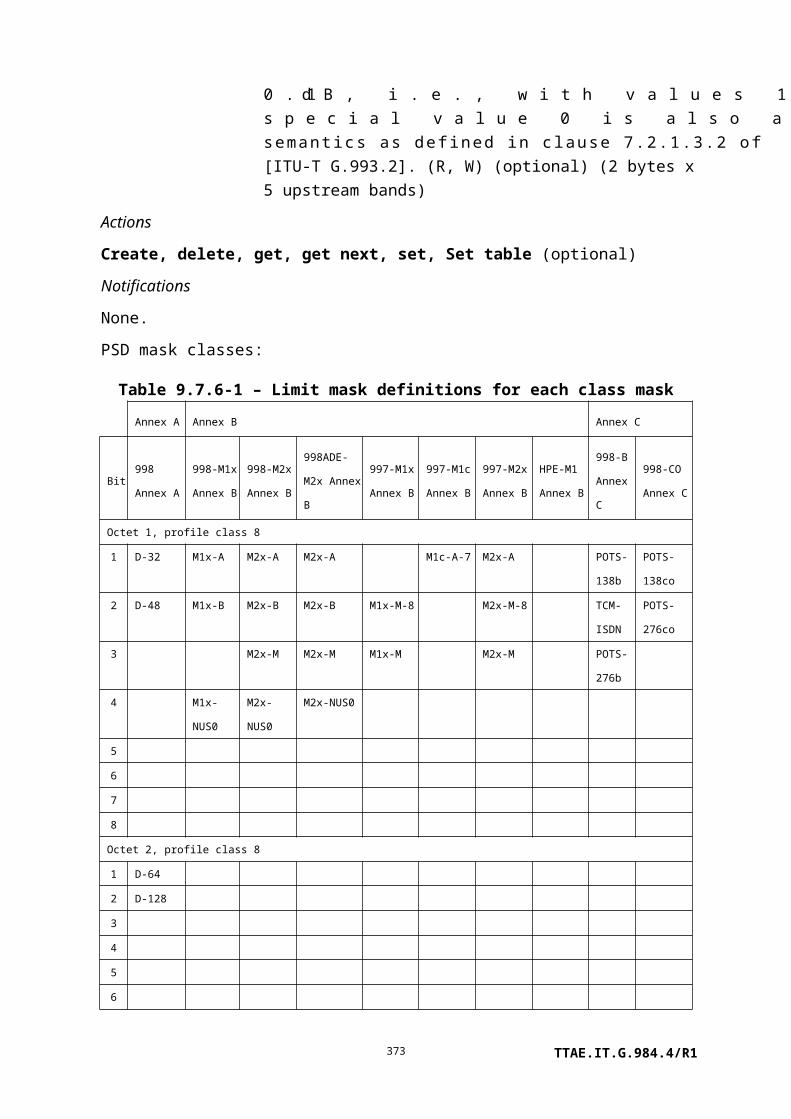
None.
9.8.4 CES physical interface performance monitoring history data
This managed entity collects statistics for a CES physical interface. Interfaces include DS1, DS3, E1, E3, J1, J2 and possibly others. The performance management requirements of particular interfaces are described in the corresponding ITU-T or other standard document, e.g., [ITU-T G.784] or [b-ATIS 0300231].
Instances of this managed entity are created and deleted by the OLT.
For a complete discussion of generic PM architecture, refer to clause I.1.9.
Relationships
An instance of this managed entity is associated with one instance of the physical path termination point CES UNI.
Attributes
Managed entity id: This attribute uniquely identifies each instance of this managed entity. Through an identical ID, this managed entity is implicitly linked to an instance of the physical path termination point CES UNI. (R, Set-by-create) (mandatory) (2 bytes)
Interval end time: This attribute identifies the most recently finished 15-minute interval. (R) (mandatory) (1 byte)
Threshold data 1/2 id: This attribute points to an instance of the threshold data 1 managed entity that contains PM threshold values. Since no mandatory threshold value attribute number exceeds 7, a threshold data 2 ME is optional. (R, W, Set-by-create) (mandatory) (2 bytes)
Errored seconds: When a detailed distinction needs to be made, this attribute corresponds to near-end line errored seconds, ES-L, also known as LES. (R) (mandatory) (2 bytes)
Severely errored seconds: When a detailed distinction needs to be made, this attribute corresponds to near-end line severely errored seconds, SES-L. (R) (mandatory) (2 bytes)
TTAE.IT.G.984.4/R1373

Burst errored seconds: A burst errored second (BES) is any second that is not a UAS, that contains between 2 and 319 error events but no LOS, AIS or OOF condition. This attribute is also known as ESB-P. (R) (optional) (2 bytes)
Unavailable seconds: When a detailed distinction needs to be made, this attribute corresponds to near-end path unavailable seconds, UAS-P. (R) (mandatory) (2 bytes)
Controlled slip seconds: When a detailed distinction needs to be made, this attribute corresponds to near-end path controlled slip seconds CSS-P. (R) (mandatory) (2 bytes)
Each of the following attributes is (R) (optional) (2 bytes).
Attribute name Common acronym
Loss of signal seconds LOSS-L
AIS seconds AISS-P
Errored seconds, path ES-P
Errored seconds, type A ESA-P
Severely errored seconds, path SES-P
Severely errored frame and AIS seconds
SAS-P aka SEFS
Code violations, line CV-L aka LCV
Code violations, path CV-P aka PCV
Errored blocks (see ITU-T G.826) EB
Actions
Create, delete, get, set
Get current data (optional)
Notifications
Threshold crossing alert
Number Threshold crossing alert Threshold value attribute # (Note)
0 ES 1
1 SES 2
TTAE.IT.G.984.4/R1374

2 BES 3
3 UAS 4
4 CSS 5
5 LOSS-L 6
6 AISS-P 7
7 ES-P 8
8 ESA-P 9
9 SES-P 10
10 SAS-P 11
11 CV-L 12
12 CV-P 13
13 EB 14
NOTE – This number associates the TCA with the specified threshold value attribute of the
threshold data 1 managed entity.
9.8.5 Pseudowire termination point
The pseudowire termination point supports packetized (rather than TDM) G-PON transport of TDM services, transported either directly over Ethernet, over UDP/IP or over MPLS. Instances of this managed entity are created and deleted by the OLT.
Relationships
One pseudowire termination point ME exists for each distinct TDM service that is mapped to a pseudowire.
Attributes
Managed entity id: This attribute uniquely identifies each instance of this managed entity. (R, Set-by-create) (mandatory) (2 bytes)
Underlying transport: 0 Ethernet, MEF8.1 UDP/IP.2 MPLS.
(R, W, Set-by-create) (mandatory) (1 byte)
Service type: This attribute specifies the basic service type, either a transparent bit pipe or an encapsulation that recognizes the underlying structure of the payload.
0 Basic unstructured (also known as structure agnostic).1 Octet-aligned unstructured, structure agnostic.
Applicable only to DS1, a mode in which each frame of 193 bits is encapsulated in 25 bytes with 7 padding bits.
2 Structured (structure-locked).
TTAE.IT.G.984.4/R1375

(R, W, Set-by-create) (mandatory) (1 byte)
Signalling: 0 No signalling visible at this layer.1 CAS, to be carried in the same packet stream as the payload.2 CAS, to be carried in a separate signalling channel.
(R, W, Set-by-create) (mandatory for structured service type) (1 byte)
TDM UNI pointer: If service type = structured, this attribute points to a logical N x 64 kbit/s sub-port connection termination point. Otherwise, this attribute points to a physical path termination point CES UNI. (R, W, Set-by-create) (mandatory) (2 bytes)
North-side pointer: When the pseudowire service is transported via IP, as indicated by the underlying transport attribute, the north-side pointer attribute points to an instance of the TCP/UDP config data managed entity. When the pseudowire service is transported directly over Ethernet, the north-side pointer attribute is not used – the linkage to the Ethernet flow termination point is implicit in the ME IDs. When the pseudowire service is transported over MPLS, the north-side pointer attribute points to an instance of the MPLS PW TP. (R, W, Set-by-create) (mandatory) (2 bytes)
Far-end IP info: When the pseudowire service is transported via IP, this attribute points to a large string managed entity that contains the URI of the far-end termination point, for example:
udp://192.168.100.221:5000 orudp://pwe3srvr.int.example.net:2222
The default value 0 is applicable if the pseudowire is not transported via IP. (R, W, Set-by-create) (mandatory for IP transport) (2 bytes)
Payload size: Number of payload bytes per packet. Valid only if service type = unstructured or unstructured octet-aligned. Valid choices depend on the TDM service, but must include the following. Other choices are at the vendor's discretion.
DS1 192.DS1 200, required only if unstructured octet-aligned
TTAE.IT.G.984.4/R1376

service is supported.E1 256.DS3 1024.E3 1024.
(R, W, Set-by-create) (mandatory for unstructured service) (2 bytes)
Payload encapsulationdelay:
Number of 125 microsecond frames to be encapsulated in each pseudowire packet. Valid only if service type = structured. The minimum set of choices for various TDM services is listed below, and is affected by the possible presence of in-band signalling. Other choices are at the vendor's discretion.
NxDS0, no signalling, N = 1 64 (8 ms) required,40 (5 ms) desired.
NxDS0, no signalling, N = 2..4 32 (4 ms).NxDS0, no signalling, N > 4 8 (1 ms).NxDS0 with DS1 CAS 24 (3 ms).NxDS0 with E1 CAS 16 (2 ms).
(R, W, Set-by-create) (mandatory for structured service) (1 byte)
Timing mode: This attribute selects the timing mode of the TDM service. If RTP is used, this attribute must be set to be consistent with the value of the RTP time stamp mode attribute in the RTP parameters managed entity at the far end.
0 Network timing (default).1 Differential timing.2 Adaptive timing.3 Loop timing: local TDM transmit clock derived
from local TDM receive stream.
(R, W) (mandatory) (1 byte)
Transmit circuit ID: This attribute is a pair of ECID (Ethernet circuit ID) values that the ONT transmits in the direction from the TDM termination toward the packet-switched network. MEF8 ECIDs lie in the range 1..1048575 (220 – 1). To allow for the possibility of other transport (L2TP) in the future, each ECID is allocated 4 bytes.
The first value is used for the payload ECID; the second is
TTAE.IT.G.984.4/R1377

used for the optional separate signalling ECID. The first ECID is required for all MEF8 pseudowires; the second is required only if signalling is to be carried in a distinct channel. If signalling is not present, or is carried in the same channel as the payload, the second ECID should be set to 0.
(R, W) (mandatory for MEF8 transport) (8 bytes)
Expected circuit ID: This attribute is a pair of ECID (Ethernet circuit ID) values that the ONT can expect in the direction from the packet-switched network toward the TDM termination. Checking ECIDs may be a way to detect circuit misconnection. MEF8 ECIDs lie in the range 1..1048575 (220 – 1). To allow for the possibility of other transport (L2TP) in the future, each ECID is allocated 4 bytes.
The first value is used for the payload ECID; the second is used for the optional separate signalling ECID. In both cases, the default value 0 indicates that no ECID checking is expected.
(R, W) (optional for MEF8 transport) (8 bytes)
Received circuit ID: This attribute indicates the actual ECID(s) received on the payload and signalling channels, respectively. It may be used for diagnostic purposes. (R) (optional for MEF8 transport) (8 bytes)
Exception policy: This attribute points to an instance of the pseudowire maintenance profile managed entity. If the pointer has its default value 0, the ONT's internal defaults apply. (R, W) (optional) (2 bytes)
ARC: See clause I.1.8. (R, W) (optional) (1 byte)
ARC interval: See clause I.1.8. (R, W) (optional) (1 byte)
Actions
Create, delete, get, set
Notifications
TTAE.IT.G.984.4/R1378

Attribute value change
Number Attribute value change Description
1..13 N/A
14 ARC Alarm reporting control cancellation
15 N/A
16 Reserved
Alarm: Alarm criteria may be customized through reference to a pseudowire maintenance profile managed object, or defined by the ONT's internal defaults.
Number Event Description
0 Misconnection Excessive ratio of stray packets received from the PSN.
1 Loss of packets Excessive ratio of lost packets from the PSN.
2 Buffer overrun Excessive ratio of packets lost because they arrived from
the PSN too early to be buffered for playout.
3 Buffer underrun Excessive ratio of packets lost because they arrived from
the PSN too late to be buffered for playout.
4 Malformed packets alarm Excessive ratio of packets lost because their structure or
payload type did not match the provisioned service.
5..207 Reserved
208..223 Vendor-specific alarms Not to be standardized
9.8.6 RTP pseudowire parameters
If a pseudowire service uses RTP, the RTP pseudowire parameters managed entity provides configuration information for the RTP layer. Instances of this managed entity are created and deleted by the OLT. The use of RTP on a pseudowire is optional, and is determined by the existence of the RTP pseudowire parameters managed entity.
Relationships
An instance of the RTP pseudowire parameters managed entity may exist for each pseudowire termination point managed entity, to which it is implicitly bound by a common managed entity ID.
Attributes
Managed entity id: This attribute uniquely identifies each instance of this managed entity. Through an identical ID, this managed entity is implicitly linked to an instance of the pseudowire termination point managed entity. (R, Set-by-
TTAE.IT.G.984.4/R1379

create) (mandatory) (2 bytes)
Clock reference: This attribute specifies the frequency of the common timing reference, in multiples of 8 kHz. The default value is 1 (8 kHz). (R, W, Set-by-create) (mandatory) (2 bytes)
TTAE.IT.G.984.4/R1380

RTP time stamp mode: This attribute determines the mode in which RTP timestamps are generated in the TDM to PSN direction.
0 Unknown or not applicable (default).
1 Absolute. Timestamps are based on the timing of the incoming TDM signal.
2 Differential. Timestamps are based on the ONT's reference clock, which is understood to be stratum-traceable along with the reference clock at the far end.
(R, W, Set-by-create) (mandatory) (1 byte)
PTYPE: This attribute specifies the RTP payload type in the TDM to PSN direction. It comprises two values. The first is for the payload channel, the second, for the optional separate signalling channel. Assignable PTYPEs lie in the dynamic range 96..127. If signalling is not transported in its own channel, the second value should be set to 0. (R, W, Set-by-create) (mandatory) (2 bytes)
SSRC: This attribute specifies the RTP synchronization source in the TDM to PSN direction. It comprises two values. The first is for the payload channel, the second, for the optional separate signalling channel. If signalling is not transported in its own channel, the second value should be set to 0. (R, W, Set-by-create) (mandatory) (8 bytes)
Expected PTYPE: This attribute specifies the RTP payload type in the PSN to TDM direction. The received payload type may be used to detect malformed packets. It comprises two values. The first is for the payload channel, the second, for the optional separate signalling channel. To disable either or both of the check functions, set the corresponding value to its default value 0. (R, W, Set-by-create) (optional) (2 bytes)
Expected SSRC: This attribute specifies the RTP synchronization source in the PSN to TDM direction. The received SSRC may be used to detect misconnection (stray packets). It comprises two values. The first is for the payload channel, the second, for the optional separate signalling channel. To disable either or both of the check functions, set the corresponding value to its default value 0. (R, W, Set-by-create) (optional) (8 bytes)
TTAE.IT.G.984.4/R1381

Actions
Create, delete, get, set
Notifications
None.
9.8.7 Pseudowire maintenance profile
The pseudowire maintenance profile permits the configuration of pseudowire service exception handling. It is created and deleted by the OLT.
The settings, and indeed existence, of a pseudowire maintenance profile affect the behaviour of the pseudowire performance monitoring history data managed entity only in establishing criteria for counting severely errored seconds, but in no other way. The pseudowire maintenance profile primarily affects the alarms declared by the subscribing pseudowire termination point.
Relationships
One or more instances of the pseudowire termination point may point to an instance of the pseudowire maintenance profile. If the pseudowire termination point does not refer to a pseudowire maintenance profile, the ONT's default exception handling is implied.
Attributes
Managed entity id: This attribute uniquely identifies each instance of this managed entity. The value 0 is reserved. (R, Set-by-create) (mandatory) (2 bytes)
Jitter buffer maximum depth:
This attribute specifies the desired maximum depth of the playout buffer in the PSN to TDM direction. The value is expressed as a multiple of the 125 μs frame rate. The default value 0 selects the ONT's internal policy. (R, W, Set-by-create) (optional) (2 bytes)
Jitter buffer desired depth: This attribute specifies the desired nominal fill depth of the playout buffer in the PSN to TDM direction. The value is expressed as a multiple of the 125 μs frame rate. The default value 0 selects the ONT's internal policy. (R, W, Set-by-create) (optional) (2 bytes)
Fill policy: This attribute defines the payload bit pattern to be applied toward the TDM service if no payload packet is available to play out. The default value 0 specifies that the ONT apply its internal policy.
0 ONT default, vendor-specific (recommended: AIS
TTAE.IT.G.984.4/R1382
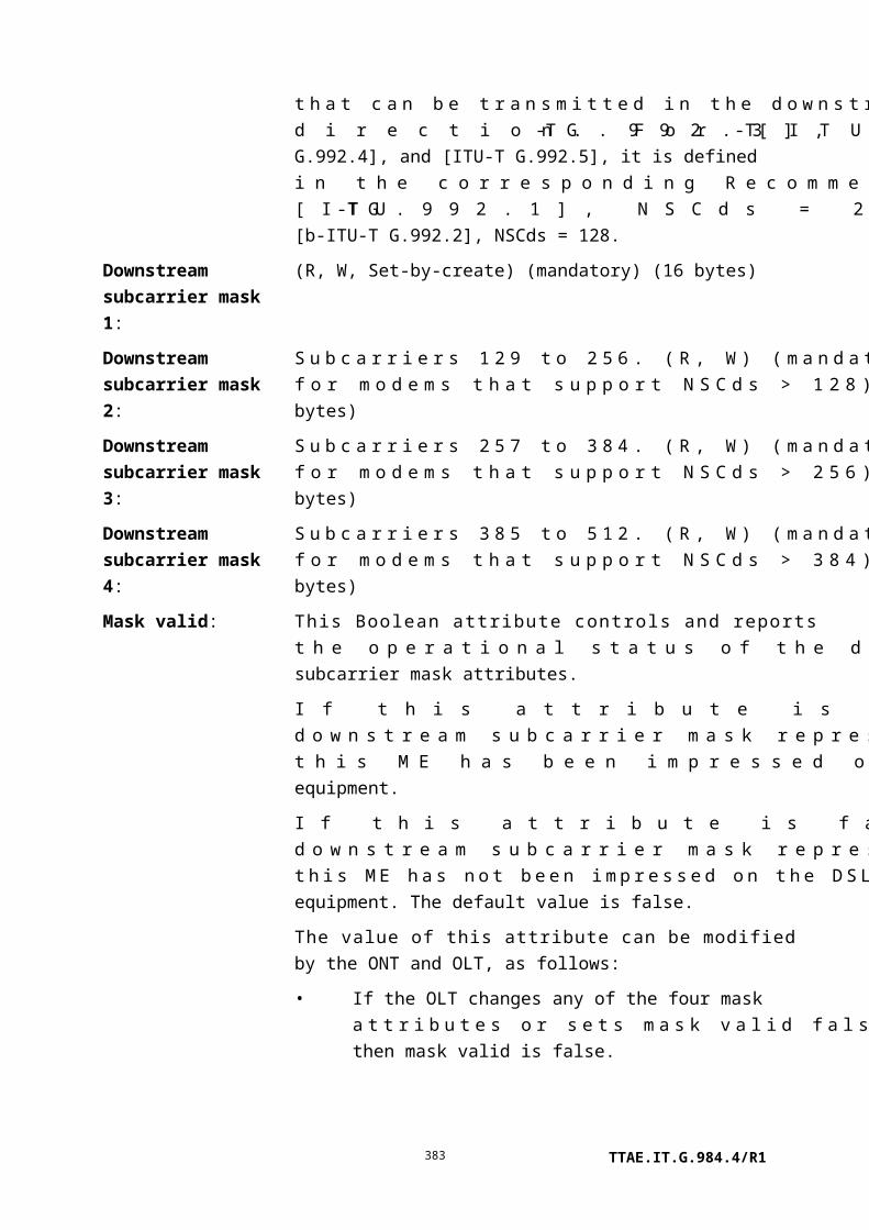
for unstructured service, all 1s for structured service).
1 Play out AIS according to the service definition (for example, DS3 AIS).
2 Play out all 1s.3 Play out all 0s.4 Repeat the previous data.5 Play out DS1 idle (Appendix C of [b-
ATIS T1.403]).6..15 Reserved for future standardization.16..255 Vendor-specific, not to be standardized.
(R, W, Set-by-create) (optional) (1 byte)
Four pairs of alarm-related policy attributes, defined below, share common behaviour.
The alarm declaration policy attribute defines the anomaly rate that causes the corresponding alarm to be declared. It is an integer percentage between 1..100. If this density of anomalies occurs during the alarm onset soak interval, the alarm is declared. The default value 0 selects the ONT's internal policy.
The alarm clear policy attribute defines the anomaly rate that causes the corresponding alarm to be cleared. It is an integer percentage between 0..99. If no more than this density of anomalies occurs during the alarm clear soak interval, the alarm is cleared. The default value 255 selects the ONT's internal policy.
Misconnected packets declaration policy:
(R, W, Set-by-create) (optional) (1 byte)
Misconnected packets clear policy:
(R, W, Set-by-create) (optional) (1 byte)
Loss of packets declaration policy:
(R, W, Set-by-create) (optional) (1 byte)
Loss of packets clear policy: (R, W, Set-by-create) (optional) (1 byte)
Buffer overrun/underrun declaration policy:
(R, W, Set-by-create) (optional) (1 byte)
Buffer overrun/underrun clear policy:
(R, W, Set-by-create) (optional) (1 byte)
Malformed packets declaration policy:
(R, W, Set-by-create) (optional) (1 byte)
Malformed packets clear (R, W, Set-by-create) (optional) (1 byte)
TTAE.IT.G.984.4/R1383

policy:
R-bit transmit set policy: This attribute defines the number of consecutive lost packets that causes the transmitted R-bit to be set in the TDM to PSN direction, indicating lost packets to the far end. The default value 0 selects the ONT's internal policy. (R, W, Set-by-create) (optional) (1 byte)
R-bit transmit clear policy: This attribute defines the number of consecutive valid packets that causes the transmitted R-bit to be cleared in the TDM to PSN direction, removing the remote failure indication to the far end. The default value 0 selects the ONT's internal policy. (R, W, Set-by-create) (optional) (1 byte)
R-bit receive policy: This attribute defines the action toward the N x 64 TDM interface when remote failure is indicated on packets received from the PSN (either R-bit set or M = 0b10 while the L-bit is cleared).
0 Do nothing (default).1 Play out service-specific RAI/REI/RDI code.2 Send channel idle signalling and idle channel payload to
all DS0s comprising the service.
(R, W, Set-by-create) (optional) (1 byte)
L-bit receive policy: This attribute defines the action toward the TDM interface when far end TDM failure is indicated on packets received from the PSN (L-bit set).
0 Play out service-specific AIS (default).1 Repeat last received packet.2 Send channel idle signalling and idle channel payload to
all DS0s comprising the service.
(R, W, Set-by-create) (optional) (1 byte)
SES threshold: Number of lost, malformed or otherwise unusable packets expected in the PSN to TDM direction within a one-second interval that causes a severely errored second to be counted. Stray packets do not count toward a severely errored second, nor do packets whose L-bit is set at the far end. The default value is 3. (R, W, Set-by-create) (optional) (2 bytes)
Actions
Create, delete, get, set
TTAE.IT.G.984.4/R1384

Notifications
None.
9.8.8 Pseudowire performance monitoring history data
This managed entity collects PM for a pseudowire termination point. Most of the attributes monitor packets received from the PSN, and may therefore be considered egress PM. For the most part, ingress PM is collected at the CES PPTP managed entity.
NOTE – The pseudowire performance monitoring history data managed entity collects data similar, but not identical, to that available from the MAC bridge port PM history data ME associated with a MAC bridge. When the pseudowire is bridge-based, it may not be necessary to collect both.
Instances of this managed entity are created and deleted by the OLT.
For a complete discussion of generic PM architecture, refer to clause I.1.9.
Relationships
An instance of this managed entity is associated with an instance of the pseudowire termination point.
Attributes
Managed entity id: This attribute uniquely identifies each instance of this managed entity. Through an identical ID, this managed entity is implicitly linked to an instance of the pseudowire termination point. (R, Set-by-create) (mandatory) (2 bytes)
Interval end time: This attribute identifies the most recently finished 15-minute interval. (R) (mandatory) (1 byte)
Threshold data 1/2 id: This attribute points to an instance of the threshold data 1 and 2 managed entities that contains PM threshold values. (R, W, Set-by-create) (mandatory) (2 bytes)
Received packets: This attribute counts the total number of packets, both payload and signalling, received in the PSN to TDM direction. (R) (mandatory) (4 bytes)
Transmitted packets: This attribute counts the total number of packets, both payload and signalling, transmitted from the TDM to the PSN. The count includes packets whose L-bit is set and which may therefore contain no payload. (R) (mandatory) (4 bytes)
Missing packets: This attribute counts the number of lost packets, as indicated by gaps in the control word numbering sequence. Both
TTAE.IT.G.984.4/R1385

payload and signalling packets, if any, contribute to this count. (R) (mandatory) (4 bytes)
Misordered packets, usable: This attribute counts the number of packets received out of order, but which were able to be successfully re-ordered and played out. Both payload and signalling packets, if any, contribute to this count. (R) (mandatory) (4 bytes)
Misordered packets dropped:
This attribute counts the number of packets received out of sequence that were discarded, either because the ONT did not support reordering or because it was too late to reorder them. Both payload and signalling packets, if any, contribute to this count. (R) (mandatory) (4 bytes)
Playout buffer underruns/overruns:
This attribute counts the number of packets that were discarded because they arrived too late or too early to be played out. Both payload and signalling packets, if any, contribute to this count. (R) (mandatory) (4 bytes)
Malformed packets: This attribute counts the number of malformed packets, for example because the packet length was not as expected or because of unexpected RTP payload type. Both payload and signalling packets, if any, contribute to this count. (R) (mandatory) (4 bytes)
Stray packets: This attribute counts the number of packets whose ECID or RTP SSRC failed to match the expected value, or which are otherwise known to have been misdelivered. Stray packets are discarded without affecting any of the other PM counters. Both payload and signalling packets, if any, contribute to this count. (R) (mandatory) (4 bytes)
Remote packet loss: This attribute counts received packets whose R-bit is set, indicating the loss of packets at the far end. Both payload and signalling packets, if any, contribute to this count. (R) (mandatory) (4 bytes)
TDM L-bit packets transmitted:
This attribute counts the number of packets transmitted with the L-bit set, indicating a near-end TDM fault. Both payload and signalling packets, if any, contribute to this count. (R) (mandatory) (4 bytes)
ES: This attribute counts errored seconds. Any discarded, lost, malformed or unusable packet received from the PSN during a given second causes this counter to increment. Both payload
TTAE.IT.G.984.4/R1386
and signalling packets, if any, contribute to this count. (R) (mandatory) (4 bytes)
SES: This attribute counts severely errored seconds. The criterion for a SES may be configured through the pseudowire maintenance profile managed entity. Both payload and signalling packets, if any, contribute to this count. (R) (mandatory) (4 bytes)
UAS: This attribute counts unavailable seconds. An unavailable second begins at the onset of ten consecutive SESs and ends at the onset of ten consecutive seconds that are not severely errored. A service is unavailable if either its payload or its signalling, if any, are unavailable. During unavailable time, only UAS should be counted; other anomalies should not be counted. (R) (mandatory) (4 bytes)
Actions
Create, delete, get, set
Get current data (optional)
Notifications
Threshold crossing alert
Number Threshold crossing alert Threshold value attribute # (Note)
0 Missing packets 1
1 Misordered packets, usable 2
2 Misordered packets dropped 3
3 Playout buffer underruns/overruns 4
4 Malformed packets 5
5 Stray packets 6
TTAE.IT.G.984.4/R1387
Threshold crossing alert
Number Threshold crossing alert Threshold value attribute # (Note)
6 Remote packet loss 7
7 ES 8
8 SES 9
9 UAS 10
NOTE – This number associates the TCA with the specified threshold value attribute of the
threshold data 1/2 managed entities.
9.8.9 Ethernet flow termination point
The Ethernet flow termination point contains the attributes necessary to originate and terminate Ethernet frames in the ONT. It is appropriate when transporting pseudowire services via layer 2. Instances of this managed entity are created and deleted by the OLT.
Relationships
One Ethernet flow termination point ME exists for each distinct pseudowire service that is transported via layer 2.
Attributes
Managed entity id: This attribute uniquely identifies each instance of this managed entity. Through an identical ID, this managed entity is implicitly linked to an instance of the ME that is the termination point of its traffic (e.g., a pseudowire termination point managed entity). (R, Set-by-create) (mandatory) (2 bytes)
Destination MAC: This attribute specifies the MAC address of the destination Ethernet frames. (R, W, Set-by-create) (mandatory) (6 bytes)
Source MAC: This attribute specifies the near-end MAC address. It is established by non-OMCI means (e.g., factory programmed into ONT flash memory) and included here for information only. (R) (mandatory) (6 bytes)
Tag policy: This attribute specifies the tagging policy to be applied to upstream Ethernet frames:
0 untagged frame (default).1 tagged frame.
(R, W, Set-by-create) (mandatory) (1 byte)
TCI: If the tag policy calls for tagging of upstream Ethernet frames,
TTAE.IT.G.984.4/R1388

this attribute specifies the tag control information, which includes the VLAN tag, P-bits and CFI bit. (R, W) (optional) (2 bytes)
Loopback: This attribute sets the loopback configuration:
0 No loopback.1 Loopback of downstream traffic at MAC client.
(R, W) (mandatory) (1 byte)
Actions
Create, delete, get, set
Notifications
None.
9.8.10 TU CTP
This managed entity organizes data that describes the TU path adaptation processing functions of the ONT for SDH services. Instances of this managed entity are created and deleted at the request of the OLT.
Relationships
One or more instances of this managed entity may be associated with an instance of a physical path termination point CES UNI that supports SDH.
Attributes
Managed entity id: This attribute provides a unique number for each instance of this managed entity. (R, Set-by-create) (mandatory) (2 bytes)
TU type: This attribute identifies the TU type. (R, Set-by-create) (mandatory) (1 byte)
1 TU-11.2 TU-12.3 TU-2.4 TU-3.
GEM frame loss integration period:
This attribute specifies the GEM frame loss integration period in milliseconds. If GEM frame loss persists for this period, the associated GEM interworking termination point generates a GEM frame starvation alarm. (R, W, Set-by-create) (mandatory) (2 bytes)
Transmit J1/J2: This attribute is the path trace byte string that the ONT
TTAE.IT.G.984.4/R1389

transmits upstream. Its default value is null. If set, the ONT inserts a byte of this attribute into the J1 or J2 into each TU payload frame. See [ITU-T G.707] for further information. (R, W, Set-by-create) (mandatory) (16 bytes)
Expected J1/J2: This attribute is the path trace byte string that the ONT expects to receive in the downstream direction. Its default value is null. If set, the ONT compares the J1 or J2 in each received TU payload with this attribute. If the received J1/J2 string differs, a TIM alarm is generated. See [ITU-T G.707] for further information. (R, W, Set-by-create) (mandatory) (16 bytes)
Received J1/J2: This attribute is the actual path trace byte string that the ONT received in the downstream direction. See [ITU-T G.707] for further information. (R) (mandatory) (16 bytes)
TIM monitor admin: This attribute specifies whether or not the TIM (trace indicator mismatch) alarm is monitored. The following code points are defined:
0 Enable.1 Disable.
Selection of a default value for this attribute is outside the scope of this Recommendation, as it is normally handled through supplier-operator negotiations. (R, W) (mandatory) (1 byte)
TIM AIS admin: This attribute indicates whether AIS is inserted when a TIM alarm occurs. The following code points are defined:
0 Enable.1 Disable.
Selection of a default value for this attribute is outside the scope of this Recommendation, as it is normally handled through supplier-operator negotiations. (R, W) (mandatory) (1 byte)
Actions
Create, delete, get, set
Notifications
Alarm
TTAE.IT.G.984.4/R1390
Number Alarm Description
0 TU3-LOP Loss of pointer alarm of TU3
1 TU3-AIS TU3 alarm indication signal
2 TU3-LOM Loss of multiframe indication (H4 mismatch or invalid
value)
3 TU3-UNEQ TU3 is unequipped with valid data
4 TU3-SLM TU3 signal label mismatch
5 TU3-TIM Trace indicator in TU3 (J1 mismatch)
6 TU3-RDI VC3 alarm indication signal (G1[b5])
7 TU3-REI VC3 remote error indication (G1[b1-b4])
8 VC3-SD VC3 signal degrade
9 VC3-SF VC3 signal fail
10 TU2-LOP Loss of pointer alarm of TU2
11 TU2-AIS TU2 alarm indication signal
12 TU2-UNEQ TU2 is unequipped with valid data
13 TU2-SLM TU2 signal label mismatch
14 TU2-TIM Trace indicator in TU2 (J2 mismatch)
15 TU2-RDI VC2 alarm indication signal (V5[b8])
16 TU2-REI VC2 remote error indication (V5[b3])
17 VC2-SD VC2 signal degrade
18 VC2-SF VC2 signal fail
19 TU12-LOP Loss of pointer alarm of TU12
20 TU12-AIS TU12 alarm indication signal
21 TU12-UNEQ TU12 is unequipped with valid data
22 TU12-SLM TU12 signal label mismatch
23 TU12-TIM Trace indicator in TU12 (J2 mismatch)
24 TU12-RDI VC12 alarm indication signal (V5[b8])
25 TU12-REI VC12 remote error indication (V5[b3])
26 VC12-SD VC12 signal degrade
27 VC12-SF VC12 signal fail
28 TU11-LOP Loss of pointer alarm of TU11
29 TU11-AIS TU11 alarm indication signal
30 TU11-UNEQ TU11 is unequipped with valid data
31 TU11-SLM TU11 signal label mismatch
32 TU11-TIM Trace indicator in TU11 (J2 mismatch)
33 TU11-RDI VC11 alarm indication signal (V5[b8])
34 TU11-REI VC11 remote error indication (V5[b3])
TTAE.IT.G.984.4/R1391

Number Alarm Description
35 VC11-SD VC11 signal degrade
36 VC11-SF VC11 signal fail
NOTE – When the received frame BER of VCn becomes 10x, the VCn-SD, VCn-SF state is
entered. The threshold X of VCn-SD and VCn-SF reuses the SD, SF threshold of the GEM frame.
9.8.11 TU performance monitoring history data
This managed entity collects performance monitoring data from SDH TUs. Most of the parameters are received from the GEM layer, and may therefore be considered egress PM. For the most part, ingress PM is collected at the CES managed entity.
Instances of this ME are created and deleted by the OLT.
For a complete discussion of generic PM architecture, refer to clause I.1.9.
Relationships
One instance of this managed entity may exist for each instance of the TU CTP managed entity.
Attributes
Managed entity id: This attribute uniquely identifies each instance of this managed entity. Through an identical ID, this managed entity is implicitly linked to an instance of a TU CTP. (R, Set-by-create) (mandatory) (2 bytes)
Interval end time: This attribute identifies the most recently finished 15-minute interval. (R) (mandatory) (1 byte)
Threshold data 1/2 id: This attribute points to an instance of the threshold data 1 and 2 managed entities that contains PM threshold values. (R, W, Set-by-create) (mandatory) (2 bytes)
Positive pointer justification:
This attribute counts pointer increments generated. (R) (mandatory) (4 bytes)
Negative pointer justification:
This attribute counts pointer decrements generated. (R) (mandatory) (4 bytes)
Near-end block error seconds:
This attribute counts near-end block errored seconds. (R) (mandatory) (4 bytes)
Near-end severely block error seconds:
This attribute counts near-end severely block errored seconds. (R) (mandatory) (4 bytes)
Remote-end block error seconds:
This attribute counts far-end block errored seconds. (R) (mandatory) (4 bytes)
TTAE.IT.G.984.4/R1392

Remote-end severely block error seconds:
This attribute counts far-end severely block errored seconds. (R) (mandatory) (4 bytes)
Near-end background block error:
This attribute counts near-end background block errors. (R) (mandatory) (4 bytes)
Remote-end background block error:
This attribute counts far-end background block errors. (R) (mandatory) (4 bytes)
Near-end unavailable seconds:
This attribute counts near-end unavailable seconds. (R) (mandatory) (4 bytes)
Remote-end unavailable seconds:
This attribute counts far-end unavailable seconds. (R) (mandatory) (4 bytes)
Actions
Create, delete, get, set
Get current data (optional)
Notifications
Threshold crossing alert
Number Threshold crossing alert Threshold value attribute # (Note)
0 Positive pointer justification 1
1 Negative pointer justification 2
2 Near-end block error seconds 3
3 Near-end severely block error seconds 4
4 Remote-end block error seconds 5
5 Remote-end severely block error
seconds
6
6 Near-end background block error 7
7 Remote-end background block error 8
8 Near-end unavailable seconds 9
9 Remote-end unavailable seconds 10
NOTE – This number associates the TCA with the specified threshold value attribute of the
threshold data 1 managed entity.
9.8.12 CES physical interface performance monitoring history data 2
This managed entity collects far-end statistics for a CES physical interface. It is specifically directed at DS1 interfaces [b-ATIS 0300231] and [b-ANSI T1.403], but may be useful in other cases as well.
TTAE.IT.G.984.4/R1393

Instances of this managed entity are created and deleted by the OLT.
For a complete discussion of generic PM architecture, refer to clause I.1.9.
Relationships
An instance of this managed entity is associated with one instance of the physical path termination point CES UNI.
Attributes
Managed entity id: This attribute uniquely identifies each instance of this managed entity. Through an identical ID, this managed entity is implicitly linked to an instance of the physical path termination point CES UNI. (R, Set-by-create) (mandatory) (2 bytes)
Interval end time: This attribute identifies the most recently finished 15-minute interval. (R) (mandatory) (1 byte)
Threshold data 1/2 id: This attribute points to an instance of the threshold data 1 and 2 managed entities that contain PM threshold values. (R, W, Set-by-create) (mandatory) (2 bytes)
Each of the following attributes is (R) (optional) (2 bytes).
Attribute name Common acronym
Errored seconds, line far-end ES-LFE
Code violations, path far-end CV-PFE
Errored seconds, path far-end ES-PFE
Errored seconds type A, path far-end ESA-PFE
Errored seconds type B, path far-end ESB-PFE
Severely errored seconds, path far-end SES-PFE
Severely errored framing seconds, path
far-end
SEFS-PFE
Unavailable seconds, path far-end UAS-PFE
Controlled slip seconds, path far-end CSS-PFE
Failure count, path far-end FC-PFE
Actions
Create, delete, get, set
Get current data (optional)
TTAE.IT.G.984.4/R1394

Notifications
Threshold crossing alert
Number Threshold crossing alert Threshold value attribute # (Note)
0 ES-LFE 1
1 CV-PFE 2
2 ES-PFE 3
3 ESA-PFE 4
4 ESB-PFE 5
5 SES-PFE 6
6 SEFS-PFE 7
7 UAS-PFE 8
8 CSS-PFE 9
NOTE – This number associates the TCA with the specified threshold value attribute of the
threshold data 1 and 2 managed entities.
9.8.13 CES physical interface performance monitoring history data 3
This managed entity collects auxiliary statistics for a CES physical interface. It is specifically directed at DS1 interfaces [b-ATIS 0300231], and [b-ANSI T1.403], but may be useful in other cases as well.
Instances of this managed entity are created and deleted by the OLT.
For a complete discussion of generic PM architecture, refer to clause I.1.9.
Relationships
An instance of this managed entity is associated with one instance of the physical path termination point CES UNI.
TTAE.IT.G.984.4/R1395

Attributes
Managed entity id: This attribute uniquely identifies each instance of this managed entity. Through an identical ID, this managed entity is implicitly linked to an instance of the physical path termination point CES UNI. (R, Set-by-create) (mandatory) (2 bytes)
Interval end time: This attribute identifies the most recently finished 15-minute interval. (R) (mandatory) (1 byte)
Threshold data 1/2 id: This attribute points to an instance of the threshold data 1 managed entity that contains PM threshold values. (R, W, Set-by-create) (mandatory) (2 bytes)
Each of the following attributes is (R) (optional) (2 bytes).
Attribute name Common acronym
AIS-CI seconds AISSCI-P
Errored seconds, network performance ES-NP
Severely errored seconds, network performance SES-NP
Unavailable seconds, network performance UAS-NP
Errored seconds, network performance, far-end ES-NPFE
Severely errored seconds, NP far-end SES-NPFE
Unavailable seconds, NP far-end UAS-NPFE
Failure count FC
Protection switch count PSC
Protection switch duration PSD
Actions
Create, delete, get, set
Get current data (optional)
Notifications
Threshold crossing alert
Number Threshold crossing alert Threshold value attribute # (Note)
0 AISSCI-P 1
1 ES-NP 2
2 SES-NP 3
TTAE.IT.G.984.4/R1396

Threshold crossing alert
Number Threshold crossing alert Threshold value attribute # (Note)
3 UAS-NP 4
4 ES-NPFE 5
5 SES-NPFE 6
6 UAS-NPFE 7
NOTE – This number associates the TCA with the specified threshold value attribute of the
threshold data 1 managed entity.
9.8.14 MPLS pseudowire termination point
This managed entity contains the underlying transport configure data of a pseudowire which underlying transportation method is MPLS. Instances of this managed entity are created and deleted by the OLT.
Relationships
Zero or one instance of this managed entity is associated with each instance of pseudowire termination point managed entity.
Attributes
Managed entity id: This attribute uniquely identifies each instance of this managed entity. (R, Set-by-create) (mandatory) (2 bytes)
TP type: This attribute specifies the type of ANI-side termination point associated with this managed entity.
1 Ethernet flow termination point2 GEM interworking TP
(R, W, Set-by-create) (mandatory) (1 byte)
TP pointer: This attribute points to the instance of the TP associated with this MPLS PW TP. The type of the associated TP is determined by the TP type attribute. (R, W, Set-by-create) (mandatory) (2 bytes)
MPLS label indicator:
This attribute specifies the MPLS label stacking situation.
0 Single MPLS labelled1 Double MPLS labelled
(R, W, Set-by-create) (mandatory) (1 byte)
MPLS PW This attribute specifies the inner MPLS direction.
TTAE.IT.G.984.4/R1397
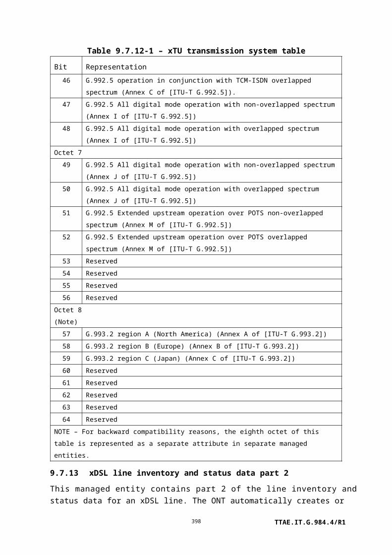
direction: 0 Upstream only1 Downstream only2 Bidirectional
(R, W, Set-by-create) (mandatory) (1 byte)
MPLS PW uplink label:
This attribute specifies the label of the inner MPLS pseudowire upstream. The attribute is not meaningful for unidirectional downstream PWs. (R, W, Set-by-create) (mandatory) (4 bytes)
MPLS PW downlink label:
This attribute specifies the label of inner MPLS pseudowire downstream. The attribute is not meaningful for unidirectional upstream PWs. (R, W, Set-by-create) (mandatory) (4 bytes)
MPLS PW EXP: This attribute specifies the inner MPLS EXP value in the upstream direction. The attribute is not meaningful for unidirectional downstream PWs. (R, W, Set-by-create) (mandatory) (1 byte)
MPLS tunnel direction:
This attribute specifies the direction of the (outer) MPLS tunnel.
0 Upstream only1 Downstream only2 Bidirectional
(R, W, Set-by-create) (mandatory) (1 byte)
MPLS tunnel uplink label:
This attribute specifies the (outer) label for the upstream MPLS tunnel. If the MPLS tunnel is downstream only, this attribute should be set to 0. (R, W, Set-by-create) (mandatory) (4 bytes)
MPLS tunnel downlink label:
This attribute specifies the (outer) label for the downstream MPLS tunnel. If the MPLS tunnel is upstream only, this attribute should be set to 0. (R, W, Set-by-create) (mandatory) (4 bytes)
MPLS tunnel EXP: This attribute specifies the EXP value of the upstream MPLS tunnel. If the MPLS tunnel is downstream only, this attribute should be set to 0. (R, W, Set-by-create) (mandatory for double MPLS labelled case) (1 byte)
Actions
Create, delete, get, set
Notifications
None.
TTAE.IT.G.984.4/R1398

9.9 Voice services
This clause defines managed entities associated with POTS (VoIP) service, as shown in Figure 9.9-1.
Figure 9.9-1 – Managed entities associated with POTS (VoIP) service
9.9.1 Physical path termination point POTS UNI
This managed entity represents the point at a POTS UNI in the ONT where a physical path terminates and physical path level functions (analogue telephony) are performed.
The ONT automatically creates an instance of this managed entity per port:
• When the ONT has POTS ports built into its factory configuration.
• When a cardholder is provisioned to expect a circuit pack of POTS type.
• When a cardholder provisioned for plug-and-play is equipped with a circuit pack of POTS type. Note that the installation of a plug-and-play card may indicate the presence of POTS ports via equipment ID as well as type, and indeed may cause the ONT to instantiate a port mapping package that specifies POTS ports.
The ONT automatically deletes instances of this managed entity when a cardholder is neither
TTAE.IT.G.984.4/R1399

provisioned to expect a POTS circuit pack, nor is it equipped with a POTS circuit pack.
Relationships
An instance of this managed entity is associated with each real or preprovisioned POTS port. SIP and VoIP voice CTPs may link to the POTS UNI, which in turn points to a GEM interworking TP. Status is available from a VoIP line status ME, and RTP and call control PM may be collected on this point.
Attributes
Managed entity id: This attribute uniquely identifies each instance of this managed entity. This two-byte number indicates the physical position of the UNI. The first byte is the slot id (defined in clause 9.1.5). If the UNI is integrated, this value is 0. The second byte is the port ID, with range 1..255. (R) (mandatory) (2 bytes)
Administrative state: This attribute locks (1) and unlocks (0) the functions performed by this managed entity. When the administrative state is set to lock, all user functions of this UNI are blocked, and alarms, TCAs and AVCs for this managed entity and all dependent managed entities are no longer generated. Selection of a default value for this attribute is outside the scope of this Recommendation. (R, W) (mandatory) (1 byte)
Interworking TP pointer: This attribute points to the associated instance of the GEM interworking termination point managed entity. The value 0 is a null pointer. This attribute is not used in VoIP and should not be supported. (R, W) (optional) (2 bytes)
ARC: See clause I.1.8. (R, W) (optional) (1 byte)
ARC interval: See clause I.1.8. (R, W) (optional) (1 byte)
Impedance: This attribute specifies the impedance for the POTS UNI. Valid values include:
0 600 Ohms.1 900 Ohms.
The following parameter sets from Annex C of [ETSI TS 101 270-1] are also defined:
2 C1=150 nF, R1=750 Ohm, R2=270 Ohm.3 C1=115 nF, R1=820 Ohm, R2=220 Ohm.4 C1=230 nF, R1=1050 Ohm, R2=320 Ohm.
TTAE.IT.G.984.4/R1400

Where C1, R1, and R2 are related as shown in Figure 9.9.1-1. Upon ME instantiation, the ONT sets this attribute to 0. (R, W) (optional) (1 byte)
Figure 9.9.1-1 – Impedance model for POTS UNI
Transmission path: This attribute allows setting the POTS UNI either to full-time on-hook transmission (0) or part-time on-hook transmission (1). Upon ME instantiation, the ONT sets this attribute to 0. (R, W) (optional) (1 byte)
Rx gain: This attribute specifies a gain value for the received signal in the form of a 2s complement number. Valid values are –120 (–12.0 dB) to 60 (+6.0 dB). Upon ME instantiation, the ONT sets this attribute to 0. (R, W) (optional) (1 byte)
Tx gain: This attribute specifies a gain value for the transmit signal in the form of a 2s complement number. Valid values are –120 (–12.0 dB) to 60 (+6.0 dB). Upon ME instantiation, the ONT sets this attribute to 0. (R, W) (optional) (1 byte)
Operational state: This attribute indicates whether or not the managed entity is capable of performing its function. Valid values are enabled (0) and disabled (1). (R) (optional) (1 byte)
Hook state: This attribute indicates the current state of the subscriber line: 0 = on hook, 1 = off hook. (R) (Optional) (1 byte)
POTS holdover time: This attribute determines the time during which POTS loop voltage is held up when the ONT is not ranged on the PON. After the specified time elapses, the ONT drops loop voltage, and may thereby cause premises intrusion alarm circuits to go active. When the ONT ranges successfully on the PON, it restores POTS loop voltage immediately and resets the timer to zero. The attribute is expressed in seconds. The default value 0 selects the vendor's factory policy. (R, W) (optional) (2 bytes)
TTAE.IT.G.984.4/R1401

Actions
Get, set
Test: Request that the ONT perform one or more MLT tests or a dial tone make/break test. Vendor-specific tests are also supported by the test and test result message layouts in clauses II.2.27 and II.2.45 (baseline message format), and in clauses II.3.27 and II.3.45 (extended message format).
Notifications
Attribute value change
Number Attribute value change Description
1..2 N/A
3 ARC ARC timer expiration
4..8 N/A
9 Op state Operational state
10..11 N/A
12..16 Reserved
9.9.2 SIP user data
The SIP user data defines the user-specific configuration attributes associated with a specific VoIP CTP. This entity is conditionally required for ONTs that offer VoIP SIP services. If a non-OMCI interface is used to manage SIP for VoIP, this ME is unnecessary. The non-OMCI interface supplies the necessary data, which may be read back to the OLT via the SIP config portal ME.
An instance of this managed entity is created and deleted by the OLT. A SIP user data instance is required for each POTS UNI port using SIP protocol and configured by OMCI.
Relationships
An instance of this managed entity is associated with one VoIP voice CTP managed entity and a PPTP POTS UNI.
Attributes
Managed entity id: This attribute uniquely identifies each instance of this managed entity. (R, Set-by-create) (mandatory) (2 bytes)
SIP agent pointer: This attribute points to the SIP agent config data ME to be used for signalling. (R, W, Set-by-create) (mandatory) (2 bytes)
User part AOR: This attribute points to a large string that contains the user
TTAE.IT.G.984.4/R1402

identification part of the address of record. This can take the form of an alphanumeric string or the subscriber's directory number. The value 0xFFFF is a null pointer. (R, W, Set-by-create) (mandatory) (2 bytes)
SIP display name: This ASCII string attribute defines the customer id used for the display attribute in outgoing SIP messages. The default value is null (all zero bytes). (R, W) (mandatory) (25 bytes)
Username/password: This attribute points to an authentication security method ME that contains the SIP user name and password used for authentication. 0xFFFF indicates no username/password. (R, W, Set-by-create) (mandatory) (2 bytes)
Voicemail server SIP URI: This attribute points to a network address ME that contains the name (IP address or URI) of the SIP voicemail server for SIP signalling messages. The default value 0xFFFF is a null pointer. (R, W, Set-by-create) (mandatory) (2 bytes)
Voicemail subscription expiration time:
This attribute defines the voicemail subscription expiration time in seconds. If this value is 0, the SIP agent uses an implementation-specific value. The default value of this attribute is 3600 seconds. (R, W, Set-by-create) (mandatory) (4 bytes)
Network dial plan pointer: This attribute points to a network dial plan table. The default value 0xFFFF is a null pointer. (R, W, Set-by-create) (mandatory) (2 bytes)
Application services profile pointer:
This attribute points to a VoIP application services profile. The default value 0xFFFF is a null pointer. (R, W, Set-by-create) (mandatory) (2 bytes)
Feature code pointer: This attribute points to the VoIP feature access codes ME for this subscriber. The default value 0xFFFF is a null pointer. (R, W, Set-by-create) (mandatory) (2 bytes)
TTAE.IT.G.984.4/R1403

PPTP pointer: This attribute points to the PPTP POTS UNI managed entity that provides the analogue telephony adaptor (ATA) function. The default value 0xFFFF is a null pointer. (R, W, Set-by-create) (mandatory) (2 bytes)
Release timer: This attribute contains a release timer defined in seconds. The value 0 specifies that the ONT is to use its internal default. The default value of this attribute is 10 seconds. (R, W) (optional) (1 byte)
ROH timer: This attribute defines the time in seconds for the receiver off hook condition before ROH tone is applied. The value 0 disables ROH timing. The default value is 15 seconds. (R, W) (optional) (1 byte)
Actions
Create, delete, get, set
Notifications
Alarm
Number Alarm Description
0 SIPUA register auth Cannot authenticate registration session (e.g., missing
credentials)
1 SIPUA register timeout Timeout waiting for response from registration server
2 SIPUA register fail Failure response received from registration server
3..207 Reserved
208..223 Vendor-specific alarms Not to be standardized
9.9.3 SIP agent config data
The SIP agent config data managed entity models a SIP signalling agent. It defines the configuration necessary to establish communication for signalling between the SIP user agent and a SIP server.
NOTE – If a non-OMCI interface is used to manage SIP for VoIP, this ME is unnecessary. The non-OMCI interface supplies the necessary data, which may be read back to the OLT via the SIP config portal ME.
Instances of this managed entity are created and deleted by the OLT.
Relationships
TTAE.IT.G.984.4/R1404

An instance of this managed entity serves one or more SIP user data managed entities and points to a TCP/UDP config data that carries signalling messages. Other pointers establish additional agent parameters such as proxy servers.
Attributes
Managed entity id: This attribute uniquely identifies each instance of this managed entity. (R, Set-by-create) (mandatory) (2 bytes)
Proxy server address pointer:
This attribute points to a large string ME that contains the name (IP address or URI) of the SIP proxy server for SIP signalling messages. (R, W, Set-by-create) (mandatory) (2 bytes)
Outbound proxy address pointer:
This attribute points to a large string ME that contains the name (IP address or URI) of the outbound proxy server for SIP signalling messages. An outbound SIP proxy may or may not be required within a given network. If an outbound SIP proxy is used, the outbound proxy address pointer attribute must be set to point to a valid large string ME. If an outbound SIP proxy is not used, the outbound proxy address pointer attribute must be set to a null pointer. (R, W, Set-by-create) (mandatory) (2 bytes)
Primary SIP DNS: This attribute specifies the primary SIP DNS IP address. If this value is 0, no primary SIP DNS is defined. The default value is 0. (R, W, Set-by-create) (mandatory) (4 bytes)
Secondary SIP DNS: This attribute specifies the secondary SIP DNS IP address. If this value is 0, no secondary SIP DNS is defined. The default value is 0. (R, W, Set-by-create) (mandatory) (4 bytes)
TCP/UDP pointer: This pointer associates the SIP agent with the TCP/UDP config data ME to be used for communication with the SIP server. The default value is 0xFFFF. (R, W) (mandatory) (2 bytes)
SIP reg exp time: This attribute specifies the SIP registration expiration time in seconds. If its value is 0, the SIP agent does not add an expiration time to the registration requests and does not perform re-registration. The default value is 3600 seconds. (R, W) (mandatory) (4 bytes)
TTAE.IT.G.984.4/R1405

SIP rereg head start time: This attribute specifies the time in seconds prior to timeout that causes the SIP agent to start the re-registration process. The default value is 360 seconds. (R, W) (mandatory) (4 bytes)
Host part URI: This attribute points to a large string ME that contains the host or domain part of the SIP address of record for users connected to this ONT. The default value 0xFFFF indicates that the current address in the IP host config ME is used. (R, W, Set-by-create) (mandatory) (2 bytes)
SIP status: This attribute shows the current status of the SIP agent. Values are as follows:
0 Ok/initial.1 Connected.2 Failed – ICMP error.3 Failed – Malformed response.4 Failed – Inadequate info response.5 Failed – Timeout.
(R) (mandatory) (1 byte)
SIP registrar: This attribute points to a network address ME that contains the name (IP address or resolved name) of the registrar server for SIP signalling messages. Examples: "10.10.10.10" and "proxy.voip.net". The default value is 0xFFFF. (R, W, Set-by-create) (mandatory) (2 bytes)
Softswitch: This attribute identifies the SIP gateway softswitch vendor. The format is four ASCII coded alphabetic characters [A..Z] as defined in [ATIS-0322000]. A value of four null characters indicates no particular vendor. (R, W, Set-by-create) (mandatory) (4 bytes)
SIP response table: This attribute specifies the tone and text to be presented to the subscriber upon reception of various SIP messages (normally 4xx, 5xx, 6xx message codes). The table is a sequence of entries, each of which is defined as follows:
SIP response code (2 bytes): This field is the index into the SIP response table. When a set operation is performed with the value 0 in this field, the table is cleared.
Tone (1 byte): This field specifies one of the tones in the tone
TTAE.IT.G.984.4/R1406

pattern table of the associated VoIP application service profile. The specified tone is played to the subscriber.
Text message (2 bytes): This field is a pointer to a large string that contains a message to be displayed to the subscriber. If the value of this field is a null pointer, text pre-associated with the tone may be displayed, or no text at all.
SIP option transmit control: This Boolean attribute specifies that the ONT is (true) or is not (false) enabled to transmit SIP options. The default value is false. (R, W, Set-by-create) (optional) (1 byte)
SIP URI format: This attribute specifies the format of the URI in outgoing SIP messages. The default value 0 specifies TEL URIs; the value 1 specifies SIP URIs. Other values are reserved. (R, W, Set-by-create) (optional) (1 byte)
Actions
Create, delete, get, set, Set table (optional)
Notifications
Attribute value change
Number Attribute value change Description
1..8 N/A
9 SIP status Status change
10..11 N/A
12..16 Reserved
Alarm
Number Alarm Description
TTAE.IT.G.984.4/R1407

0 SIPUA register name Failed to resolve the registration server name
1 SIPUA register reach Cannot reach registration server (the port
cannot be reached, ICMP errors)
2 SIPUA register connect Cannot connect to registration server (due to
bad credentials or other fault after the port
responded)
3 SIPUA register validate Cannot validate registration server
4 (Note) SIPUA register auth Cannot authenticate registration session (e.g.,
missing credentials)
5 (Note) SIPUA register timeout Timeout waiting for response from registration
server
6 (Note) SIPUA register fail Failure response received from registration
server
7..207 Reserved
208..223 Vendor-specific alarms Not to be standardized
NOTE – These alarms are deprecated, and retained for backward compatibility. It is
recommended that the SIP agent config data not declare these alarms, but that they be declared by
the SIP user data ME instead. In any event, only one ME should declare the alarm, not both.
9.9.4 VoIP voice CTP
The VoIP voice CTP defines the attributes necessary to associate a specified VoIP service (SIP (e.g., [b-IETF RFC 3261]), [ITU-T H.248.x]) with a POTS UNI. This entity is conditionally required for ONTs that offer VoIP services. If a non-OMCI interface is used to manage VoIP signalling, this ME is unnecessary. The non-OMCI interface supplies the necessary data, which may be read back to the OLT via the SIP config portal ME or the MGC config portal ME.
An instance of this managed entity is created and deleted by the OLT. A VoIP voice CTP managed object is needed for each PPTP POTS UNI served by VoIP.
Relationships
An instance of this managed entity links a PPTP POTS managed entity with a VoIP media profile and a SIP user data or MGC config data ME.
Attributes
TTAE.IT.G.984.4/R1408

Managed entity id: This attribute uniquely identifies each instance of this managed entity. (R, Set-by-create) (mandatory) (2 bytes)
User protocol pointer: This attribute points to signalling protocol data. If the signalling protocol used attribute of the VoIP config data managed entity specifies that the ONT's signalling protocol is SIP, this attribute points to a SIP user data ME, which in turn points to a SIP agent config data. If the signalling protocol is H.248, this attribute points directly to an MGC config data ME. (R, W, Set-by-create) (mandatory) (2 bytes)
PPTP pointer: This attribute points to the PPTP POTS UNI managed entity that serves the analogue telephone port. (R, W, Set-by-create) (mandatory) (2 bytes)
VoIP media profile pointer: This attribute points to an associated VoIP media profile. (R, W, Set-by-create) (mandatory) (2 bytes)
Signalling code: This attribute specifies the POTS-side signalling:
1 Loop start.2 Ground start.3 Loop reverse battery.4 Coin first.5 Dial tone first.6 Multi-party.
(R, W, Set-by-create) (mandatory) (1 byte)
Actions
Create, delete, get, set
Notifications
None.
9.9.5 VoIP media profile
The VoIP media profile managed entity contains settings that apply to VoIP voice encoding. This entity is conditionally required for ONTs that offer VoIP services. If a non-OMCI interface is used to manage VoIP signalling, this ME is unnecessary. The non-OMCI interface supplies the necessary data, which may be read back to the OLT via the SIP config portal ME or the MGC config portal ME.
An instance of this managed entity is created and deleted by the OLT. A VoIP media profile is needed for each unique set of profile attributes.
TTAE.IT.G.984.4/R1409

Relationships
An instance of this managed entity may be associated with one or more VoIP voice CTP managed entities.
Attributes
Managed entity id: This attribute uniquely identifies each instance of this managed entity. (R, Set-by-create) (mandatory) (2 bytes)
Fax mode: Selects the fax mode; values are:
0 Passthru.1 T.38.
The default value is 0. (R, W, Set-by-create) (mandatory) (1 byte)
Voice service profile pointer:
Pointer to a voice service profile. This ME defines jitter, echo cancellation and PSTN data. (R, W, Set-by-create) (mandatory) (2 bytes)
Codec selection (1st order): This attribute specifies codec selection as defined by [IETF RFC 3551]. The default value is 0, PCMU.
Value Encoding name Clock rate (Hz)
0 PCMU 8,000
1 Reserved
2 Reserved
3 GSM 8,000
4 G723 8,000
5 DVI4 8,000
6 DVI4 16,000
7 LPC 8,000
8 PCMA 8,000
9 G722 8,000
10 L16, 2 channels 44,100
11 L16, 1 channel 44,100
12 QCELP 8,000
TTAE.IT.G.984.4/R1410

13 CN 8,000
14 MPA 90,000
15 G728 8,000
16 DVI4 11,025
17 DVI4 22,050
18 G729 8,000
(R, W, Set-by-create) (mandatory) (1 byte)
Packet period selection (1st order):
This attribute specifies the packet period selection interval in milliseconds. The default value is 10. Valid values are 10..30 ms. (R, W, Set-by-create) (mandatory) (1 byte)
Silence suppression (1st order):
This attribute specifies whether silence suppression is on or off. Valid values are 0 = off and 1 = on. (R, W, Set-by-create) (mandatory) (1 byte)
Three more groups of three attributes are defined, with definitions identical to the preceding three:
Codec selection (2nd order): (R, W, Set-by-create) (mandatory) (1 byte)
Packet period selection (2nd order): (R, W, Set-by-create) (mandatory) (1 byte)
Silence suppression (2nd order): (R, W, Set-by-create) (mandatory) (1 byte)
Codec selection (3rd order): (R, W, Set-by-create) (mandatory) (1 byte)
Packet period selection (3rd order): (R, W, Set-by-create) (mandatory) (1 byte)
Silence suppression (3rd order): (R, W, Set-by-create) (mandatory) (1 byte)
Codec selection (4th order): (R, W, Set-by-create) (mandatory) (1 byte)
Packet period selection (4th order): (R, W, Set-by-create) (mandatory) (1 byte)
Silence suppression (4th order): (R, W, Set-by-create) (mandatory) (1 byte)
OOB DTMF: This attribute specifies out-of-band DMTF carriage. When enabled (1), DTMF signals are carried out of band via RTP or the associated signalling protocol. When disabled, DTMF tones are carried in the PCM stream. (R, W, Set-by-create) (mandatory) (1 byte)
RTP profile pointer: This attribute points to the associated RTP profile data ME. (R, W, Set-by-create) (mandatory) (2 bytes)
TTAE.IT.G.984.4/R1411

Actions
Create, delete, get, set
Notifications
None.
9.9.6 Voice service profile
NOTE – Except for the change of name, this managed entity is substantially identical to the voice service profile AAL managed entity defined in [ITU-T G.983.2].
This managed entity organizes data that describes the voice service functions of the ONT. Instances of this managed entity are created and deleted by the OLT.
Relationships
An instance of this managed entity may be associated with zero or more instances of a VoIP voice CTP by way of a VoIP media profile.
Attributes
Managed entity id: This attribute uniquely identifies each instance of this managed entity. (R, Set-by-create) (mandatory) (2 bytes)
Announcement type: This attribute specifies the treatment when a subscriber goes off hook but does not attempt a call. Valid values include:
0x01 Silence.0x02 Reorder tone.0x03 Fast busy.0x04 Voice announcement.0xFF N/A.
(R, W, Set-by-create) (mandatory) (1 byte)
TTAE.IT.G.984.4/R1412

Jitter target: This attribute specifies the target value of the jitter buffer in milliseconds. The system tries to maintain the jitter buffer at the target value. The value 0 specifies dynamic jitter buffer sizing. (R, W, Set-by-create) (optional) (2 bytes)
Jitter buffer max: This attribute specifies the maximum depth of the jitter buffer associated with this service in milliseconds. (R, W, Set-by-create) (optional) (2 bytes)
Echo cancel ind: The Boolean value true specifies that echo cancellation is on; false specifies off. (R, W, Set-by-create) (mandatory) (1 byte)
PSTN protocol variant: This attribute controls which variant of POTS signalling is used on the associated UNIs. Its value is equal to the E.164 country code. (R, W, Set-by-create) (optional) (2 bytes)
DTMF digit levels: This attribute specifies the power level of DTMF digits that may be generated by the ONT toward the subscriber set. It is a 2s complement value referred to 1 mW at the 0 TLP (dBm0), with resolution 1 dB. The default value 0x8000 selects the ONT's internal policy. (R, W, Set-by-create) (optional) (2 bytes)
DTMF digit duration: This attribute specifies the duration of DTMF digits that may be generated by the ONT toward the subscriber set. It is specified in milliseconds. The default value 0 selects the ONT's internal policy. (R, W, Set-by-create) (optional) (2 bytes)
Hook flash minimum time: This attribute defines the minimum duration recognized by the ONT as a switchhook flash. It is expressed in milliseconds; the default value 0 selects the ONT's internal policy. (R, W, Set-by-create) (optional) (2 bytes)
Hook flash maximum time: This attribute defines the maximum duration recognized by the ONT as a switchhook flash. It is expressed in milliseconds; the default value 0 selects the ONT's internal policy. (R, W, Set-by-create) (optional) (2 bytes)
Tone pattern table: This attribute is a table each of whose entries specifies a complex tone (or silence) and a duration. By linking tones and silence together, possibly cyclically, continuous, varying or interrupted tone sequences, repetitive or not, may be defined. A tone sequence is initiated by pointing to the first tone pattern table entry that defines its parameters. Each entry
TTAE.IT.G.984.4/R1413

is a vector comprising the following components:
Index (1 byte): This component is simply an index into the table. It ranges from 1..255. In a set operation, the value 0 in this field clears the table.
Tone on (1 byte): This Boolean component controls whether the tone is on (true) or off. If the tone is off, the frequency and power fields are not meaningful.
Frequency 1 (2 bytes): This component specifies the frequency of one of the tone components in Hz.
Power 1 (1 byte): This component specifies the power level of the corresponding frequency component. It ranges from 0..25.5 dBm0 with 0.1 dB resolution. Three additional pairs of frequency-power components may be specified to define a complex tone. If a pair of possibilities is not to be used, its frequency field should be set to 0.
Frequency 2 (2 bytes)
Power 2 (1 byte)
Frequency 3 (2 bytes)
Power 3 (1 byte)
Frequency 4 (2 bytes)
Power 4 (1 byte)
The following pair of frequency-power components allows the composite tone to be modulated (warble effect). If this effect is not to be used, the frequency should be set to 0.
Modulation frequency (2 bytes), Hz
Modulation power (1 byte), 0..25.5 dBm0
Duration (2 bytes): This component specifies the duration of the phase, in milliseconds. The value 0 specifies that the phase endures indefinitely, that is, until terminated by other events such as call abandonment.
Next entry (1 byte): This component is a pointer to another entry in this same table, which permits sequences of tones to be defined, possibly cyclically. A reference to a non-existent table entry, or the value 0, indicates that the sequence should
TTAE.IT.G.984.4/R1414

be terminated.
(R, W) (optional) (N * 20 bytes)
Tone event table: This attribute is a table each of whose entries specifies an event for which a tone is defined. If the tone can be synthesized by a sequence of complex tones and silence, the event refers to an entry in the tone pattern table. Otherwise, the event refers to a file name that is expected to be recognized by the ONT environment. Each entry in the tone event table is a vector comprising the following components:
Event (1 byte): This component is an enumeration of the events for which a tone may be defined. The event component also serves as the index for the table. A set operation to event 0 causes the table to be cleared.
Value Tone event
0 Not used for get operation; clears table under set operation
1 Busy2 Confirmation3 Dial4 Message waiting5 Off hook warning (receiver off hook)6 Ringback (audible ring)7 Reorder8 Stutter dial9 Call waiting 1
10 Call waiting 211 Call waiting 312 Call waiting 413 Alerting signal14 Special dial15 Special info16 Release17 Congestion18 User defined 119 User defined 220 User defined 321 User defined 4
TTAE.IT.G.984.4/R1415

22..32 Reserved33 Intrusion34 Dead tone
35..223
Reserved
224..255
Vendor specific codes, not to be standardized
Tone pattern (1 byte): This component specifies an entry point into the tone pattern table attribute, to be invoked when the specified event occurs. The value 0 indicates that no tone from the tone pattern table is to be played.
Tone file (2 bytes): This component points to a large string managed entity that contains the path and name of a file containing a codec sequence to be played out. If no file is found after traversing these links, no tone is played. The behaviour is unspecified if both tone pattern and tone file are specified.
Tone file repetitions (1 byte): This component specifies the number of times the tone file is to be repeated. The value 0 means that the file is to be repeated indefinitely until terminated by some external event such as call abandonment.
Reserved (2 bytes)
(R, W) (optional) (N * 7 bytes)
Ringing pattern table: This attribute is a table each of whose entries specifies a ringing pattern and a duration. By linking ringing and silence together, possibly cyclically, continuous or interrupted ringing sequences, repetitive or not, may be defined. A ringing sequence is initiated by pointing to the first ringing pattern table entry that defines its parameters. Each entry is a vector comprising the following components:
Index (1 byte): This component is simply an index into the table. It ranges from 1..255. In a set operation, the value 0 in this field clears the table.
Ringing on (1 byte): This Boolean component controls whether ringing is on (true) or off during this interval.
TTAE.IT.G.984.4/R1416

Duration (2 bytes): This component specifies the duration of the ringing phase, in milliseconds. The value 0 specifies that the phase lasts indefinitely, that is, until terminated by other events such as call abandonment.
Next entry (1 byte): This component is a pointer to another entry in this same table, which permits sequences of ringing bursts to be defined, possibly cyclically. A reference to a non-existent table entry, or the value 0, indicates that the sequence should be terminated.
(R, W) (optional) (N * 5 bytes)
Ringing event table: This attribute is a table each of whose entries specifies an event for which a ringing sequence is defined. If the ringing sequence can be generated as a sequence of power ringing and silent intervals, the event refers to an entry in the ringing pattern table. Otherwise, the event refers to a file name that is expected to be recognized by the ONT environment. Each entry is a vector comprising the following components:
Event (1 byte): This component is an enumeration of the events for which a ringing sequence may be defined. The event component also serves as the index for the table. A set operation with the value 0 in this field causes the table to be cleared.
Value Tone event
0 Not used for get operation; clears table under set operation
1 Default2 Splash
3..223 Reserved224..255 Vendor specific codes, not to be
standardized
Ringing pattern (1 byte): This component specifies an entry point into the ringing pattern table attribute, to be invoked when the specified event occurs. The value 0 indicates that no ringing sequence is defined in the ringing pattern table.
Ringing file (2 bytes): This component points to a large string managed entity that contains the path and name of a file
TTAE.IT.G.984.4/R1417

containing a ring tone to be played out. If no file is found after traversing these links, no ringing is played. The behaviour is unspecified if both ringing pattern and ringing file fields are specified.
Ringing file repetitions (1 byte): This component specifies the number of times the ringing file is to be repeated. The value 0 means that the file is to be repeated indefinitely until terminated by some external event such as call abandonment.
Ringing text (2 bytes): This component points to a large string managed entity that contains a text string to be displayed on the CPE device in conjunction with this event. A null pointer indicates that no text is to be displayed.
(R, W) (optional) (N * 7 bytes)
Actions
Create, delete, get, set, Set table (optional)
Notifications
None.
9.9.7 RTP profile data
This managed entity configures RTP. It is conditionally required for ONTs that offer VoIP service. If a non-OMCI interface is used to manage VoIP, this ME is unnecessary. The non-OMCI interface supplies the necessary data, which may be read back to the OLT via the SIP config portal or the MGC config portal ME.
An instance of this managed entity is created and deleted by the OLT. An RTP profile is needed for each unique set of attributes.
Relationships
An instance of this managed entity may be associated with one or more VoIP media profile managed entities.
Attributes
Managed entity id: This attribute uniquely identifies each instance of this managed entity. (R, Set-by-create) (mandatory) (2 bytes)
Local port min: This attribute defines the base RTP port that should be used for voice traffic. The default is 50000. (R, W, Set-by-create) (mandatory) (2 bytes)
Local port max: This attribute defines the highest RTP port used for voice traffic.
TTAE.IT.G.984.4/R1418

The default must be greater than local port min but is determined by vendor application. (R, W, Set-by-create) (optional) (2 bytes)
DSCP mark: Diffserv code point to be used for outgoing RTP packets for this profile. The default value is expedited forwarding (EF) = 0x2E. (R, W, Set-by-create) (mandatory) (1 byte)
Piggyback events: Enables or disables RTP piggyback events.
0 Disabled (default).1 Enabled.
(R, W, Set-by-create) (mandatory) (1 byte)
Tone events: Enables or disables handling of tones via RTP tone events per [IETF RFC 4733] (see also [IETF RFC 4734]).
0 Disabled (default).1 Enabled.
(R, W, Set-by-create) (mandatory) (1 byte)
DTMF events: Enables or disables handling of DTMF via RTP DTMF events per [IETF RFC 4733] (see also [IETF RFC 4734]). This attribute is ignored unless the OOB DTMF attribute in the VoIP media profile is enabled.
0 Disabled (default).1 Enabled.
(R, W, Set-by-create) (mandatory) (1 byte)
CAS events: Enables or disables handling of CAS via RTP CAS events per [IETF RFC 4733] (see also [IETF RFC 4734]).
0 Disabled (default).1 Enabled.
(R, W, Set-by-create) (mandatory) (1 byte)
Actions
Create, delete, get, set
Notifications
None.
9.9.8 VoIP application service profile
The VoIP application service profile defines attributes of calling features used in conjunction with a VoIP line service. It is optional for ONTs that support VoIP service. If a non-OMCI
TTAE.IT.G.984.4/R1419

interface is used to manage SIP for VoIP, this ME is unnecessary. The non-OMCI interface supplies the necessary data, which may be read back to the OLT via the SIP config portal ME.
An instance of this managed entity is created and deleted by the OLT. A VoIP application service managed object is needed for each unique set of profile attributes.
Relationships
An instance of this managed entity is associated with zero or more SIP user data MEs.
Attributes
Managed entity id: This attribute uniquely identifies each instance of this managed entity. (R, Set-by-create) (mandatory) (2 bytes)
CID features: This attribute contains a bit map of caller ID features. Except as noted, the value 0 disables the feature; 1 enables it.
0x01 Calling number0x02 Calling name0x04 CID blocking (both number and name)0x08 CID number – Permanent presentation status
for number(0 = public, 1 = private)
0x10 CID name – Permanent presentation status for name (0 = public, 1 = private)
0x20 Anonymous CID blocking (ACR). It may not be possible to support this in the ONT.
0x40..0x80 Not used
The default value is disabled. (R, W, Set-by-create) (mandatory) (1 byte)
Call waiting features: This attribute contains a bit map of call waiting features. The value 0 disables the feature; 1 enables it.
0x01 Call waiting0x02 Caller ID announcement0x04..0x80 Not used
The default value is disabled. (R, W, Set-by-create) (mandatory) (1 byte)
Call progress or transfer features:
This attribute is a bit map of call processing features. The value 0 disables the feature; 1 enables it.
0x0001 3way
TTAE.IT.G.984.4/R1420

0x0002 Call transfer0x0004 Call hold0x0008 Call park0x0010 Do not disturb0x0020 Flash on emergency service call (flash is to be
processed during an emergency service call)0x0040 Emergency service originating hold
(determines whether call clearing is to be performed on on-hook during an emergency service call)
0x0080 6way0x0100..0x8000 Not used
The default value is disabled. (R, W, Set-by-create) (mandatory) (2 bytes)
Call presentation features:
This attribute is a bit map of call presentation features. The value 0 disables the feature; 1 enables it.
0x0001 Message waiting indication splash ring0x0002 Message waiting indication special dial tone0x0004 Message waiting indication visual indication0x0008 Call forwarding indication0x0010..0x8000 Not used
The default value is disabled. (R, W, Set-by-create) (mandatory) (2 bytes)
Direct connect feature: This attribute is a bit map of characteristics associated with the direct connect feature. The value 0 disables the feature; 1 enables it.
0x01 Direct connect feature enabled0x02 Dial tone feature delay option
The default value is disabled. (R, W, Set-by-create) (mandatory) (1 byte)
Direct connect URI pointer:
If this attribute is set to its default value 0xFFFF, no URI is defined. Otherwise, this attribute points to a network address managed entity that specifies the URI of the direct connect. (R, W, Set-by-create) (mandatory) (2 bytes)
Bridged line agent URI pointer:
If this attribute is set to its default value 0xFFFF, no URI is defined. Otherwise, this attribute points to a network address managed entity that specifies the URI of the bridged line agent.
TTAE.IT.G.984.4/R1421

(R, W, Set-by-create) (mandatory) (2 bytes)
Conference factory URI pointer:
If this attribute is set to its default value 0xFFFF, no URI is defined. Otherwise, this attribute points to a network address managed entity that specifies the URI of the conference factory. (R, W, Set-by-create) (mandatory) (2 bytes)
Actions
Create, delete, get, set
Notifications
None.
9.9.9 VoIP feature access codes
The VoIP feature access codes managed entity defines administrable feature access codes for the VoIP subscriber. It is optional for ONTs that support VoIP service. If a non-OMCI interface is used to manage VoIP signalling, this ME is unnecessary. The non-OMCI interface supplies the necessary data, which may be read back to the OLT via the SIP config portal ME.
Instances of the managed entity are created and deleted by the OLT. A VoIP feature access codes managed object is needed for each unique set of feature access code attributes.
Relationships
An instance of this managed entity may be associated with one or more SIP user data managed entities.
Attributes
Managed entity id: This attribute uniquely identifies each instance of this managed entity. (R) (mandatory) (2 bytes)
The remaining attributes are access codes for the features mentioned in their names. Each attribute is a string of characters from the set {0..9, *, #}, with trailing nulls in any unused bytes.
Cancel call waiting: (R, W) (optional) (5 bytes)
Call hold: (R, W) (optional) (5 bytes)
Call park: (R, W) (optional) (5 bytes)
Caller ID activate: (R, W) (optional) (5 bytes)
Caller ID deactivate: (R, W) (optional) (5 bytes)
Do not disturb activation: (R, W) (optional) (5 bytes)
TTAE.IT.G.984.4/R1422

Do not disturb deactivation: (R, W) (optional) (5 bytes)
Do not disturb PIN change: (R, W) (optional) (5 bytes)
Emergency service number: (R, W) (optional) (5 bytes)
Intercom service: (R, W) (optional) (5 bytes)
Actions
Create, delete, get, set, Set table (optional)
Notifications
None.
9.9.10 Network dial plan table
The network dial plan table ME is optional for ONTs providing VoIP service. This ME is used to provision dial plans from the OLT. Instances of this managed entity are created and deleted by the OLT. If a non-OMCI interface is used to manage SIP for VoIP, this ME is unnecessary. The non-OMCI interface supplies the necessary data, which may be read back to the OLT via the SIP config portal ME.
Relationships
An instance of this managed entity may be associated with one or more instances of the SIP user data managed entity.
Attributes
Managed entity id: This attribute uniquely identifies each instance of this managed entity. (R, Set-by-create) (mandatory) (2 bytes)
Dial plan number: This attribute indicates the current number of dial plans in the dial plan table. Default value is 0. (R) (mandatory) (2 bytes)
Dial plan table max size: This attribute defines the maximum number of dial plans that can be stored in the dial plan table. (R, Set-by-create) (mandatory) (2 bytes)
Critical dial timeout: This attribute defines the critical dial timeout for digit map processing in milliseconds. The default value is 4000 ms. (R, W, Set-by-create) (mandatory) (2 bytes)
Partial dial timeout: This attribute defines the partial dial timeout for digit map processing in milliseconds. The default value is 16000 ms. (R, W, Set-by-create) (mandatory) (2 bytes)
Dial plan format: This attribute defines the dial plan format standard that is supported in the ONT for VoIP. Valid values include:
TTAE.IT.G.984.4/R1423

0 Not defined.1 H.248 format with specific plan (table entries define the
dialling plan).2 NSC format.3 Vendor-specific format.
The default is 1. (R, W, Set-by-create) (mandatory) (1 byte)
Dial plan table: The table contains a dial plan used by the VoIP service, along with fields to manage the table. These table attributes are further described below. (R, W) (mandatory) (30N bytes, where N is the number of dial plans)
Dial plan id: A unique identifier of a dial plan within the dial plan table. (1 byte)
Action: Remove (0) or add (1) this plan (set action). When a dial plan is being removed, only the dial plan id field is used to identify the dial plan token. (1 byte)
Dial plan token: Token used by the VoIP service to process dial plans. This ASCII string is typically delimited by ":". (28 bytes)
Actions
Create, delete, get, get next, set
Notifications
None.
9.9.11 VoIP line status
The VoIP line status managed entity contains line status information for POTS ports using VoIP service. An ONT that supports VoIP automatically creates or deletes an instance of this managed entity upon creation or deletion of a PPTP POTS UNI.
Relationships
An instance of this managed entity is associated with a PPTP POTS UNI.
Attributes
Managed entity id: This attribute uniquely identifies each instance of this managed entity. Through an identical ID, this managed entity is implicitly linked to an instance of the physical path termination point POTS UNI. (R) (mandatory) (2 bytes)
voip codec used: Reports the current codec used for a VoIP POTS port. Valid values are taken from [IETF RFC 3551], the same as specified in
TTAE.IT.G.984.4/R1424

the codec selection attribute in the VoIP media profile:0 PCMU
1 Reserved
2 Reserved
3 GSM
4 G723
5 DVI4
6 DVI4
7 LPC
8 PCMA
9 G722
10 L16, 2 channels
11 L16, 1 channel
12 QCELP
13 CN
14 MPA
15 G728
16 DVI4
17 DVI4
18 G729
(R) (mandatory) (2 bytes)
TTAE.IT.G.984.4/R1425

voip voice server status: Status of the VoIP session for this POTS port:
0 None/initial1 Registered2 In session3 Failed registration – icmp error4 Failed registration – failed tcp5 Failed registration – failed authentication6 Failed registration – timeout7 Failed registration – server fail code8 Failed invite – icmp error9 Failed invite – failed tcp10 Failed invite – failed authentication11 Failed invite – timeout12 Failed invite – server fail code13 Port not configured14 Config done
(R) (mandatory) (1 byte)
voip port session type: This attribute reports the current state of a VoIP POTS port session:
0 Idle/none1 2way2 3way3 Fax4 Telem5 Conference
(R) (mandatory) (1 byte)
voip call 1 packet period:
This attribute reports the packet period for the first call on the VoIP POTS port. The value is defined in milliseconds. (R) (mandatory) (2 bytes)
voip call 2 packet period:
This attribute reports the packet period for the second call on the VoIP POTS port. The value is defined in milliseconds. (R) (mandatory) (2 bytes)
voip call 1 dest addr: This attribute reports the destination address for the first call on the VoIP POTS port. The value is an ASCII string. (R) (mandatory) (25 bytes)
voip call 2 dest addr: This attribute reports the destination address for the second call
TTAE.IT.G.984.4/R1426

on the VoIP POTS port. The value is an ASCII string. (R) (mandatory) (25 bytes)
Actions
Get
Notifications
None.
9.9.12 Call control performance monitoring history data
This managed entity collects performance monitoring data related to the call control channel. Instances of this managed entity are created and deleted by the OLT.
For a complete discussion of generic PM architecture, refer to clause I.1.9.
Relationships
An instance of this managed entity is associated with an instance of the PPTP POTS UNI managed entity.
Attributes
Managed entity id: This attribute uniquely identifies each instance of this managed entity. Through an identical ID, this managed entity is implicitly linked to an instance of the PPTP POTS UNI. (R, Set-by-create) (mandatory) (2 bytes)
Interval end time: This attribute identifies the most recently finished 15-minute interval. (R) (mandatory) (1 byte)
Threshold data 1/2 id: This attribute points to an instance of the threshold data 1 managed entity that contains PM threshold values. Since no threshold value attribute number exceeds 7, a threshold data 2 ME is optional. (R, W, Set-by-create) (mandatory) (2 bytes)
Call setup failures: This attribute counts call setup failures. (R) (mandatory) (4 bytes)
Call setup timer: This attribute is a high water mark that records the longest duration of a single call setup detected during this interval. Time is measured in milliseconds from the time an initial setup was requested by the subscriber until the time at which a response was provided to the subscriber in the form of busy tone, audible ring tone, etc. (R) (mandatory) (4 bytes)
Call terminate failures: This attribute counts the number of calls that were terminated with cause. (R) (mandatory) (4 bytes)
TTAE.IT.G.984.4/R1427

Analog port releases: This attribute counts the number of analogue port releases without dialling detected (abandoned calls). (R) (mandatory) (4 bytes)
Analog port off-hook timer:
This attribute is a high water mark that records the longest period of a single off-hook detected on the analogue port. Time is measured in milliseconds. (R) (mandatory) (4 bytes)
Actions
Create, delete, get, set
Get current data (optional)
Notifications
Threshold crossing alert
Number Threshold crossing alert Threshold value attribute # (Note)
0 CCPM call setup fail 1
1 CCPM setup timeout 2
2 CCPM call terminate 3
3 CCPM port release with no dialling 4
4 CCPM port offhook timeout 5
NOTE – This number associates the TCA with the specified threshold value attribute of the
threshold data 1 managed entity.
9.9.13 RTP performance monitoring history data
NOTE – This managed entity was formerly known under the name RTP monitoring data.
This managed entity collects performance monitoring data related to an RTP session. Instances of this managed entity are created and deleted by the OLT.
For a complete discussion of generic PM architecture, refer to clause I.1.9.
Relationships
An instance of this managed entity is associated with an instance of the PPTP POTS UNI managed entity.
Attributes
Managed entity id: This attribute uniquely identifies each instance of this managed entity. Through an identical ID, this managed entity is implicitly linked to an instance of the PPTP POTS UNI ME. (R, Set-by-create) (mandatory) (2 bytes)
Interval end time: This attribute identifies the most recently finished 15-minute
TTAE.IT.G.984.4/R1428

interval. (R) (mandatory) (1 byte)
Threshold data 1/2 id: This attribute points to an instance of the threshold data 1 managed entity that contains PM threshold values. Since no threshold value attribute number exceeds 7, a threshold data 2 ME is optional. (R, W, Set-by-create) (mandatory) (2 bytes)
RTP errors: This attribute counts RTP packet errors. (R) (mandatory) (4 bytes)
Packet loss: This attribute represents the fraction of packets lost. This attribute is calculated at the end of the 15-minute interval, and is undefined under the get current data action. The value 0 indicates no packet loss, scaling linearly to 0xFFFF to indicate 100% packet loss (zero divided by zero is defined to be zero). (R) (mandatory) (4 bytes)
Maximum jitter: This attribute is a high water mark that represents the maximum jitter identified during the measured interval, expressed in RTP timestamp units. (R) (mandatory) (4 bytes)
Maximum time between RTCP packets:
This attribute is a high water mark that represents the maximum time between RTCP packets during the measured interval, in milliseconds. (R) (mandatory) (4 bytes)
Buffer underflows: This attribute counts the number of times the reassembly buffer underflows. In case of continuous underflow caused by a loss of IP packets, a single buffer underflow should be counted. If the interworking function is implemented with multiple buffers, such as a packet level buffer and a bit level buffer, then underflow of either buffer increments this counter. (R) (mandatory) (4 bytes)
Buffer overflows: This attribute counts the number of times the reassembly buffer overflows. If the interworking function is implemented with multiple buffers, such as a packet level buffer and a bit level buffer, then overflow of either buffer increments this counter. (R) (mandatory) (4 bytes)
Actions
Create, delete, get, set
Get current data (optional)
Notifications
Threshold crossing alert
TTAE.IT.G.984.4/R1429
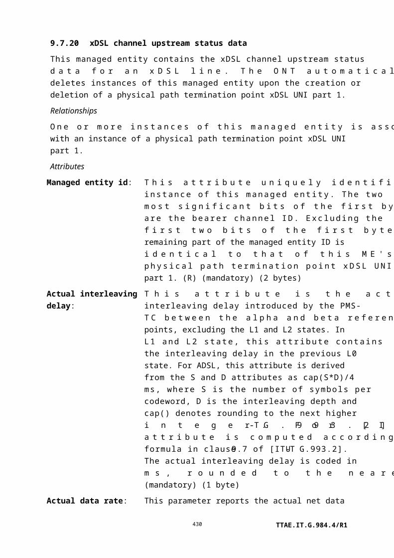
Number Threshold crossing alert Threshold value attribute # (Note 2)
0 RTP errors 1
1 Packet loss (Note 1) 2
2 Maximum jitter 3
3 Max time between RTCP packets 4
4 Buffer underflows 6
5 Buffer overflows 7
9.9.14 SIP agent performance monitoring history data
NOTE – This managed entity was formerly known by the name SIP agent monitoring data.
This managed entity collects performance monitoring data for the associated VoIP SIP agent. Instances of this managed entity are created and deleted by the OLT.
For a complete discussion of generic PM architecture, refer to clause I.1.9.
Relationships
An instance of this managed entity is associated with a SIP agent config data or SIP config portal object.
Attributes
Managed entity id: This attribute uniquely identifies each instance of this managed entity. Through an identical ID, this managed entity is implicitly linked to an instance of the corresponding SIP agent config data. If a non-OMCI configuration method is used for VoIP, the managed entity id is 0. (R, Set-by-create) (mandatory) (2 bytes)
Interval end time: This attribute identifies the most recently finished 15-minute interval. (R) (mandatory) (1 byte)
Threshold data 1/2 id: This attribute points to an instance of the threshold data 1 managed entity that contains PM threshold values. Since no threshold value attribute number exceeds 7, a threshold data 2 ME is optional. (R, W, Set-by-create) (mandatory) (2 bytes)
Transactions: This attribute counts the number of new transactions that were initiated. (R) (optional) (4 bytes)
Rx invite reqs: This attribute counts received invite messages, including retransmissions. (R) (optional) (4 bytes)
Rx invite retrans: This attribute counts received invite retransmission messages. (R) (optional) (4 bytes)
Rx noninvite reqs: This attribute counts received non-invite messages, including
TTAE.IT.G.984.4/R1430

retransmissions. (R) (optional) (4 bytes)
Rx noninvite retrans: This attribute counts received non-invite retransmission messages. (R) (optional) (4 bytes)
Rx response: This attribute counts total responses received. (R) (optional) (4 bytes)
Rx response retransmissions:
This attribute counts total response retransmissions received. (R) (optional) (4 bytes)
Tx invite reqs: This attribute counts transmitted invite messages, including retransmissions. (R) (optional) (4 bytes)
Tx invite retrans: This attribute counts transmitted invite retransmission messages. (R) (optional) (4 bytes)
Tx noninvite reqs: This attribute counts transmitted non-invite messages, including retransmissions. (R) (optional) (4 bytes)
Tx noninvite retrans: This attribute counts transmitted non-invite retransmission messages. (R) (optional) (4 bytes)
Tx response: This attribute counts the total responses sent. (R) (optional) (4 bytes)
Tx response retransmissions:
This attribute counts total response retransmissions sent. (R) (optional) (4 bytes)
Actions
Create, delete, get, set
Get current data (optional)
Notifications
Threshold crossing alert
Number Threshold crossing alert Threshold value attribute # (Note)
0 SIPAMD rx invite req 1
1 SIPAMD rx invite req retransmission 2
2 SIPAMD rx noninvite req 3
3 SIPAMD rx noninvite req retransmission 4
4 SIPAMD rx response 5
5 SIPAMD rx response retransmission 6
NOTE – This number associates the TCA with the specified threshold value attribute of the
threshold data 1 managed entity.
TTAE.IT.G.984.4/R1431
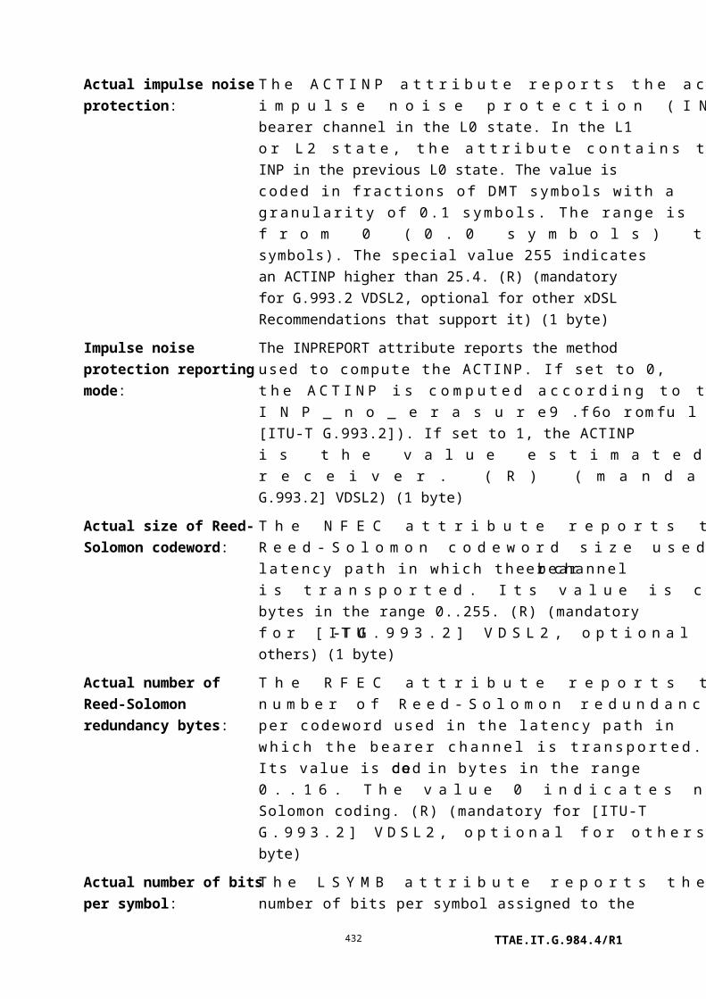
9.9.15 SIP call initiation performance monitoring history data
This managed entity collects performance monitoring data related to call initiations of a VoIP SIP agent. Instances of this managed entity are created and deleted by the OLT.
For a complete discussion of generic PM architecture, refer to clause I.1.9.
Relationships
An instance of this managed entity is associated with an instance of the SIP agent config data or SIP config portal ME.
Attributes
Managed entity id: This attribute uniquely identifies each instance of this managed entity. Through an identical ID, this managed entity is implicitly linked to an instance of SIP agent config data. If a non-OMCI configuration method is used for VoIP, the managed entity id is 0. (R, Set-by-create) (mandatory) (2 bytes)
Interval end time: This attribute identifies the most recently finished 15-minute interval. (R) (mandatory) (1 byte)
Threshold data 1/2 id: This attribute points to an instance of the threshold data 1 managed entity that contains PM threshold values. Since no threshold value attribute number exceeds 7, a threshold data 2 ME is optional. (R, W, Set-by-create) (mandatory) (2 bytes)
Failed to connect counter:
This attribute counts the number of times the SIP UA failed to reach/connect its TCP/UDP peer during SIP call initiations. (R) (mandatory) (4 bytes)
Failed to validate counter:
This attribute counts the number of times the SIP UA failed to validate its peer during SIP call initiations. (R) (mandatory) (4 bytes)
Timeout counter: This attribute counts the number of times the SIP UA timed out during SIP call initiations. (R) (mandatory) (4 bytes)
Failure received counter:This attribute counts the number of times the SIP UA received a failure error code during SIP call initiations. (R) (mandatory) (4 bytes)
Failed to authenticate counter:
This attribute counts the number of times the SIP UA failed to authenticate itself during SIP call initiations. (R) (mandatory) (4 bytes)
Actions
Create, delete, get, set
TTAE.IT.G.984.4/R1432

Get current data (optional)
Notifications
Threshold crossing alert
Number Threshold crossing alert Threshold value attribute # (Note)
0 SIP call PM failed connect 1
1 SIP call PM failed to validate 2
2 SIP call PM timeout 3
3 SIP call PM failure recv 4
4 SIP call PM failed to authenticate 5
NOTE – This number associates the TCA with the specified threshold value attribute of the
threshold data 1 managed entity.
9.9.16 MGC config data
The MGC config data ME defines the media gateway controller configuration associated with an MG subscriber. It is conditionally required for ONTs that support H.248 VoIP service. If a non-OMCI interface is used to manage VoIP signalling, this ME is unnecessary. The non-OMCI interface supplies the necessary data, which may be read back to the OLT via the MGC config portal ME.
Instances of this managed entity are created and deleted by the OLT.
Relationships
An instance of this managed entity may be associated with one or more VoIP voice CTP managed entities.
Attributes
Managed entity id: This attribute uniquely identifies each instance of this managed entity. (R, Set-by-create) (mandatory) (2 bytes)
Primary MGC: This attribute points to a network address ME that contains the name (IP address or resolved name) of the primary MGC that controls the signalling messages. The port is optional and defaults to 2944 for text message formats and 2955 for binary message formats. (R, W, Set-by-create) (mandatory) (2 bytes)
Secondary MGC: This attribute points to a network address ME that contains the name (IP address or resolved name) of the secondary or backup MGC that controls the signalling messages. The port is optional and defaults to 2944 for text message formats and 2955 for binary message formats. (R, W, Set-by-create) (mandatory) (2 bytes)
TCP/UDP pointer: This attribute points to the TCP/UDP config data ME to be used
TTAE.IT.G.984.4/R1433

for communication with the MGC. The default value 0 is a null pointer. (R, W, Set-by-create) (mandatory) (2 bytes)
Version: This integer attribute reports the version of the Megaco protocol in use. (R, W, Set-by-create) (mandatory) (1 byte)
Message format: This attribute defines the message format. Valid values are:
0 Text long1 Text short2 Binary
The default value is 0. (R, W, Set-by-create) (mandatory) (1 byte)
Maximum retry time: This attribute specifies the maximum retry time for MGC transactions, in seconds. The default value 0 specifies vendor-specific implementation (R, W) (optional) (2 bytes)
Maximum retry attempts:
This attribute specifies the maximum number of times a message is retransmitted to the MGC. The default value 0 specifies vendor-specific implementation. (R, W, Set-by-create) (optional) (2 bytes)
Service change delay: The attribute specifies the service status delay time for changes in line service status. This attribute is specified in seconds. The default value 0 specifies no delay. (R, W) (optional) (2 bytes)
Termination ID base: The attribute specifies the base string for the H.248 physical termination id(s) for this ONT. This string is intended to uniquely identify an ONT. Vendor-specific termination identifiers (i.e., port IDs) are optionally added to this string to uniquely identify a termination on a specific ONT. (R, W) (optional) (25 bytes)
Softswitch: This attribute identifies the gateway softswitch vendor. The format is four ASCII coded alphabetic characters [A..Z] as defined in [ATIS-0322000]. A value of four null characters indicates no particular vendor. (R, W, Set-by-create) (mandatory) (4 bytes)
Actions
Create, delete, get, set
Notifications
Alarm
Number Alarm Description
TTAE.IT.G.984.4/R1434

0 Timeout Timeout of association with MG
1..207 Reserved
208..223 Vendor-specific alarms Not to be standardized
9.9.17 MGC performance monitoring history data
NOTE – This managed entity was formerly known under the name MGC monitoring data.
The MGC monitoring data managed entity provides run-time statistics for an active MGC association. Instances of this managed entity are created and deleted by the OLT.
For a complete discussion of generic PM architecture, refer to clause I.1.9.
Relationships
An instance of this managed entity is associated with an instance of the MGC config data or MGC config portal ME.
Attributes
Managed entity id: This attribute uniquely identifies each instance of this managed entity. Through an identical ID, this managed entity is implicitly linked to an instance of the associated MGC config data. If a non-OMCI configuration method is used, the managed entity id is 0. (R, Set-by-create) (mandatory) (2 bytes)
Interval end time: This attribute identifies the most recently finished 15-minute interval. (R) (mandatory) (1 byte)
Threshold data 1/2 id: This attribute points to an instance of the threshold data 1 managed entity that contains PM threshold values. Since no threshold value attribute number exceeds 7, a threshold data 2 ME is optional. (R, W, Set-by-create) (mandatory) (2 bytes)
Received messages: This attribute counts the number of received Megaco messages on this association, as defined by [ITU-T H.341]. (R) (mandatory) (4 bytes)
Received octets: This attribute counts the total number of octets received on this association, as defined by [ITU-T H.341]. (R) (mandatory) (4 bytes)
Sent messages: This attribute counts the total number of Megaco messages sent over this association, as defined by [ITU-T H.341]. (R) (mandatory) (4 bytes)
Sent octets: This attribute counts the total number of octets sent over this association, as defined by [ITU-T H.341]. (R) (mandatory) (4 bytes)
TTAE.IT.G.984.4/R1435

Protocol errors: This attribute counts the total number of errors detected on this association, as defined by [ITU-T H.341]. This includes:
• Syntax errors detected in a given received message.• Outgoing transactions that failed for protocol reasons.
(R) (mandatory) (4 bytes)
Transport losses: This attribute counts the total number of transport losses (for example, socket problems) detected on this association. A link loss is defined as loss of communication with the remote entity due to hardware/transient problems, or problems in related software. (R) (mandatory) (4 bytes)
Last detected event: This attribute reports the last event detected on this association. This includes events such as the link failing or being set up. This field is an enumeration:
0 No event – No event has been detected as yet.1 Link up – The transport link underpinning the association
came up.2 Link down – The transport link underpinning the association
went down.3 Persistent error – A persistent error was detected on the link
(such as the socket/TCP connection to the remote node could not be set up).
4 Local shutdown – The association was brought down intentionally by the local application.
5 Failover down – The association was brought down as part of failover processing.
255 Other event – The last event does not match any in the list.
(R) (mandatory) (1 byte)
Last detected event time:This attribute reports the time in seconds since the last event on this association was detected, as defined by [ITU-T H.341]. (R) (mandatory) (4 bytes)
Last detected reset time: This attribute reports the time in seconds since these statistics were last reset, as defined by [ITU-T H.341]. Under normal circumstances, a get action on this attribute would return 900 seconds to indicate a completed 15-minute interval. (R) (mandatory) (4 bytes)
Actions
TTAE.IT.G.984.4/R1436

Create, delete, get, set
Get current data (optional)
Notifications
Threshold crossing alert
Number Threshold crossing alert Threshold value attribute # (Note)
0 MGCP protocol errors 1
1 MGCP transport losses 2
NOTE – This number associates the TCA with the specified threshold value attribute of the
threshold data 1 managed entity.
9.9.18 VoIP config data
The VoIP configuration data managed entity defines the configuration for VoIP in the ONT. The OLT uses this ME to discover the VoIP signalling protocols and configuration methods supported by this ONT. The OLT then uses this ME to select the desired signalling protocol and configuration method. The entity is conditionally required for ONTs that offer VoIP services.
An ONT that supports VoIP services automatically creates an instance of this managed entity.
Relationships
One instance of the managed entity is associated with the ONT.
Attributes
Managed entity id: This attribute uniquely identifies each instance of this managed entity. There is only one instance, number 0. (R) (mandatory) (2 bytes)
Available signalling protocols:
This attribute is a bit map that defines the VoIP signalling protocols supported in the ONT. Valid values are any combination of:
0 None, VoIP not supported.1 SIP.2 H.248.4 MGCP.
(R) (mandatory) (1 byte)
TTAE.IT.G.984.4/R1437

Signalling protocol used: This attribute specifies the VoIP signalling protocol to use. Only one type of protocol is allowed at a time. Valid values are:
0 None.1 SIP.2 H.248.3 MGCP.0xFF Selected by non-OMCI management interface.
(R, W) (mandatory) (1 byte)
Available VoIP configuration methods:
This attribute is a bit map that indicates the capabilities of the ONT with regard to VoIP service configuration:
1 ONT capable of using OMCI to configure its VoIP services.2 ONT capable of working with configuration file
retrieval to configure its VoIP services.4 ONT capable of working with DSL Forum TR-69 to
configure its VoIP services.8 ONT capable of working with IETF sipping config
framework to configure its VoIP services.
Bits 5..24 are reserved for future use. Bits 25..32 are reserved for proprietary vendor configuration capabilities. (R) (mandatory) (4 bytes)
VoIP configuration method used:
Specifies which method is used to configure the ONT's VoIP service.
0 Do not configure – ONT default.1 OMCI.2 Configuration file retrieval.3 DSL Forum TR-69.4 IETF sipping config framework.5..240 Reserved for future use.241..255 Reserved for proprietary vendor configuration methods.
(R, W) (mandatory) (1 byte)
VoIP configuration address pointer:
If this attribute is set to any value other than 0xFFFF, it points to a network address managed entity, which indicates the address of the server to contact using the method indicated in the VoIP configuration method used attribute. This attribute is only
TTAE.IT.G.984.4/R1438

relevant for non-OMCI configuration methods.
If this attribute is set to 0xFFFF, no address is defined by this attribute. However, the address may be defined by other methods, such as deriving it from the ONT identifier attribute of the IP host config data ME and using a well-known URI schema. (The default value is 0xFFFF.) (R, W) (mandatory) (2 bytes)
VoIP configuration state:
Indicates the status of the ONT VoIP service.
0 Inactive: Configuration retrieval has not been attempted.1 Active: Configuration was retrieved.2 Initializing: Configuration is now being retrieved.3 Fault: Configuration retrieval process failed.
Other values are reserved. At ME instantiation, the ONT sets this attribute to 0. (R) (mandatory) (1 byte)
Retrieve profile: This attribute provides a means by which the ONT may be notified that a new VoIP profile should be retrieved. By setting this attribute, the OLT triggers the ONT to retrieve a new profile. The actual value in the set action is ignored because it is the action of setting that is important. (W) (mandatory) (1 byte)
Profile version: This attribute is a character string that identifies the version of the last retrieved profile. (R) (mandatory) (25 bytes)
Actions
Get, set
Notifications
Attribute value change
Number Attribute value change Description
1..7 N/A
8 Profile version Version of last retrieved profile
9..16 Reserved
Alarm
Number Alarm Description
0 VCD config server name Failed to resolve the configuration server name
TTAE.IT.G.984.4/R1439

Alarm
Number Alarm Description
1 VCD config server reach Cannot reach configuration server (the port cannot
be reached, ICMP errors)
2 VCD config server connect Cannot connect to configuration server (due to bad
credentials or other fault after the port responded)
3 VCD config server validate Cannot validate configuration server
4 VCD config server auth Cannot authenticate configuration session (e.g.,
missing credentials)
5 VCD config server timeout Timeout waiting for response from configuration
server
6 VCD config server fail Failure response received from configuration server
7 VCD config file error Configuration file received has an error
8 VCD subscription name Failed to resolve the subscription server name
9 VCD subscription reach Cannot reach subscription server (the port cannot be
reached, ICMP errors)
10 VCD subscription connect Cannot connect to subscription server (due to bad
credentials or other fault after the port responded)
11 VCD subscription validate Cannot validate subscription server
12 VCD subscription auth Cannot authenticate subscription session (e.g.,
missing credentials)
13 VCD subscription timeout Timeout waiting for response from subscription
server
14 VCD subscription fail Failure response received from subscription server
15 VCD reboot request A non-OMCI management interface has requested a
reboot of the ONT.
NOTE – This alarm is used only to indicate the
request and not to indicate that a reboot has actually
taken place.
16..207 Reserved
208..223 Vendor-specific alarms Not to be standardized
9.9.19 SIP config portal
The SIP config portal managed entity provides a way for the OLT to discover the configuration text delivered to an ONT by a non-OMCI SIP VoIP configuration method (TR-69, Sipping framework, etc.). Text retrieved from this ME is not required to be understood by the OLT or EMS, but it may be useful for human or vendor-specific analysis tools. See also the MGC config portal ME.
TTAE.IT.G.984.4/R1440

An instance of this managed entity may be created by an ONT that supports non-OMCI SIP configuration. It is not reported during a MIB upload.
Relationships
One instance of this managed entity is associated with the ONT.
Attributes
Managed entity ID: This attribute uniquely identifies each instance of this managed entity. There is one instance, number 0. (R) (mandatory) (2 bytes)
Configuration text table: This attribute is used to pass a textual representation of the VoIP configuration back to the OLT. The contents are vendor-specific. The get, get next sequence must be used with this attribute since its size is unspecified. Upon ME instantiation, the ONT sets this attribute to 0. (R) (mandatory) (x bytes)
Actions
Get, get next
Notifications
Attribute value change
Number Attribute value change Description
1 Configuration text Indicates an update to the VoIP configuration from a
non-OMCI interface. Because the attribute is a table, the
AVC contains no information about its value. The OLT
must use the get, get next action sequence if it wishes to
obtain the updated attribute content.
2..16 Reserved
9.9.20 MGC config portal
The MGC (media gateway controller) config portal managed entity provides a way for the OLT to discover the configuration text delivered to an ONT by a non-OMCI H.248 VoIP configuration method. Text retrieved from this ME is not required to be understood by the OLT or EMS, but it may be useful for human or vendor-specific analysis tools. See also the SIP config portal ME.
An instance of this managed entity may be created by an ONT that supports non-OMCI H.248 configuration. It is not reported during a MIB upload.
Relationships
One instance of this managed entity is associated with the ONT.
Attributes
TTAE.IT.G.984.4/R1441

Managed entity id: This attribute uniquely identifies each instance of this managed entity. There is one instance, number 0. (R, Set-by-create) (mandatory) (2 bytes)
Configuration text table: This attribute is used to pass a textual representation of the VoIP configuration back to the OLT. The contents are vendor-specific. The get, get next sequence must be used with this attribute since its size is unspecified. Upon ME instantiation, the ONT sets this attribute to 0. (R) (mandatory) (x bytes)
Actions
Get, get next
Notifications
Attribute value change
Number Attribute value change Description
1 Configuration text Indicates an update to the VoIP configuration from a
non-OMCI interface. Because the attribute is a table,
the AVC contains no information about its value. The
OLT must use the get, get next action sequence if it
wishes to obtain the updated attribute content.
2..16 Reserved
9.9.21 Physical path termination point ISDN UNI
This managed entity represents the point at a basic rate ISDN UNI where physical paths terminate and physical path level functions (e.g., analogue telephony, facsimile function) are performed.
The ONT automatically creates an instance of this managed entity per port:
• When the ONT has ISDN ports built into its factory configuration.
• When a cardholder is provisioned to expect a circuit pack of ISDN type.
• When a cardholder provisioned for plug-and-play is equipped with a circuit pack of ISDN type. Note that the installation of a plug-and-play card may indicate the presence of ISDN ports via equipment ID as well as its type, and indeed may cause the ONT to instantiate a port mapping package that specifies ISDN ports.
The ONT automatically deletes instances of this managed entity when a cardholder is neither provisioned to expect an ISDN circuit pack, nor is it equipped with an ISDN circuit pack.
Relationships
TTAE.IT.G.984.4/R1442
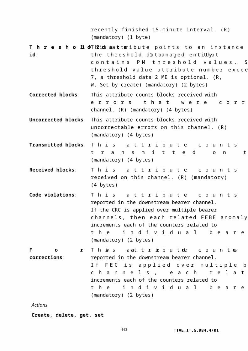
One or more instances of this managed entity are associated with the ONT-G or a circuit pack managed entity classified as ISDN type.
Attributes
Managed entity id: This attribute uniquely identifies each instance of this managed entity. This two-byte number indicates the physical position of the UNI. The first byte is the slot id (defined in clause 9.1.5). The second byte is the port ID, with range 1..255. (R) (mandatory) (2 bytes)
TTAE.IT.G.984.4/R1443
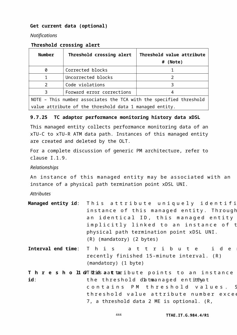
Administrative state: This attribute locks (1) and unlocks (0) the functions performed by this managed entity. When the administrative state is set to lock, all user functions of this UNI are blocked, and alarms, TCAs and AVCs for this managed entity and all dependent managed entities are no longer generated. Selection of a default value for this attribute is outside the scope of this Recommendation. (R, W) (mandatory) (1 byte)
Interworking pointer: This attribute points to the instance of the GEM interworking termination point managed entity to which this instance is connected. The value 0 is a null pointer. (R, W) (optional) (2 bytes)
D channel ID: This attribute contains the channel identifier of the connection transporting the D channel associated with this ISDN BRI port. (R, W) (mandatory) (1 byte)
B1 channel ID: This attribute contains the channel identifier of the connection transporting the B1 channel associated with this ISDN BRI port. (R, W) (mandatory) (1 byte)
B2 channel ID: This attribute contains the channel identifier of the connection transporting the B2 channel associated with this ISDN BRI port. (R, W) (mandatory) (1 byte)
ARC: See clause I.1.8. (R, W) (optional) (1 byte)
ARC interval: See clause I.1.8. (R, W) (optional) (1 byte)
ISDN loopback configuration:
This attribute controls the loopback configuration of this physical interface.
0 No loopback.1 Simultaneous loopback of all channels.1 Loopback of D channel only [sic].2 Loopback of B1 channel only.3 Loopback of B2 channel only.
Upon ME instantiation, the ONT sets this attribute to 0. (R, W) (mandatory) (1 byte)
Actions
Get, set
Test: Request that the ONT perform one or more MLT tests. See test and test result message layouts in clauses II.2.27 and II.2.45 (baseline message
TTAE.IT.G.984.4/R1444

format) and in clauses II.3.27 and II.3.45 (extended message format).
Notifications
Attribute value change
Number Attribute value change Description
1..5 N/A
6 ARC ARC timer expiration
7..8 N/A
9..16 Reserved
Alarm
Number Alarm Description
0 AIS Alarm indication signal
1 RDI Remote defect indication
2..207 Reserved
208..223 Vendor-specific alarms Not to be standardized
9.10 MoCA
This clause defines managed entities associated with MoCA UNIs, as shown in Figure 9.10-1.
Figure 9.10-1 – Managed entities associated with MoCA UNIs
9.10.1 Physical path termination point MoCA UNI
This managed entity represents a MoCA UNI, where physical paths terminate and physical path level functions (i.e., the MoCA function) are performed.
The ONT automatically creates an instance of this managed entity per port:
• When the ONT has MoCA ports built into its factory configuration.
• When a cardholder is provisioned to expect a circuit pack of MoCA type.
• When a cardholder provisioned for plug-and-play is equipped with a circuit pack of MoCA type. Note that the installation of a plug-and-play card may indicate the
TTAE.IT.G.984.4/R1445

presence of MoCA ports via equipment ID as well as its type, and indeed may cause the ONT to instantiate a port mapping package that specifies MoCA ports.
The ONT automatically deletes instances of this managed entity when a cardholder is neither provisioned to expect a MoCA circuit pack, nor is it equipped with a MoCA circuit pack.
Relationships
An instance of this managed entity is associated with each real or preprovisioned MoCA port.
Attributes
Managed entity id: This attribute uniquely identifies each instance of this managed entity. This two-byte number is directly associated with the physical position of the UNI. The first byte is the slot id (defined in clause 9.1.5). The second byte is the port ID, with range 1..255. (R) (mandatory) (2 bytes)
Loopback configuration: This attribute sets the MoCA loopback configuration:
0 No loopback.3 Loopback3, loopback of downstream traffic after PHY
transceiver, depicted in Figure 9.10.1-1.
Upon ME instantiation, the ONT sets this attribute to 0. (R, W) (optional) (1 byte)
Figure 9.10.1-1 – MoCA loopback configuration
Note that normal bridge behaviour may defeat the loopback signal, unless broadcast MAC addresses are used.
Administrative state: This attribute locks (1) and unlocks (0) the functions performed by this managed entity. When the administrative state is set to lock, all user functions of this UNI are blocked, and alarms, TCAs and AVCs for this managed entity and all dependent managed entities are no longer generated. Selection of a default value for this attribute is outside the scope of this Recommendation. (R, W) (mandatory) (1 byte)
Operational state: This attribute indicates whether or not the managed entity is capable of performing its function. Valid values are enabled (0)
TTAE.IT.G.984.4/R1446

and disabled (1). (R) (optional) (1 byte)
Max frame size: This attribute denotes the maximum frame size allowed across this interface. Upon ME instantiation, the ONT sets this attribute to 1518. (R, W) (mandatory) (2 bytes)
ARC: See clause I.1.8. (R, W) (optional) (1 byte)
ARC interval: See clause I.1.8. (R, W) (optional) (1 byte)
PPPoE filter: This attribute controls filtering of PPPoE packets on this MoCA port. When its value is 1, all packets other than PPPoE packets are discarded. The default 0 accepts packets of all types. (R, W) (optional) (1 byte)
Network status: This attribute indicates the networking state of the MoCA interface.
0 The interface has not joined a MoCA network.1 The interface has joined a MoCA network.2 The interface has joined a MoCA network and is currently the
network coordinator.
(R) (mandatory) (1 byte)
Password: This attribute specifies the MoCA encryption key. It is an ASCII string of 17 decimal digits. Upon ME instantiation, the ONT sets this attribute to 17 null bytes. (R, W) (mandatory) (17 bytes)
Privacy enabled: This attribute activates (1) link-layer security. The default value 0 deactivates it. (R, W) (mandatory) (1 byte)
Minimum bandwidth alarm threshold:
This attribute specifies the minimum desired PHY link bandwidth between two nodes. If the actual bandwidth is lower, a limited link alarm is declared. Valid values are 0 to 0x0410 (260 Mbit/s) in 0.25-Mbit/s increments. The default value is 0x02D0 (180 Mbit/s). The value 0 disables the threshold. (R, W) (optional) (2 bytes)
TTAE.IT.G.984.4/R1447

Frequency mask: This attribute is a bit map of the centre frequencies that the interface is permitted to use, where each bit represents a centre frequency. The least significant bit (b[1]) corresponds to centre frequency 800 MHz. The next significant bit (b[2]) corresponds to centre frequency 825 MHz. The 28th bit (b[28]) corresponds to a centre frequency 1500 MHz. The 4 most significant bits are not used. (R, W) (optional) (4 bytes)
RF channel: This attribute reports the frequency to which the MoCA interface is currently tuned, in MHz. (R) (mandatory) (2 bytes)
Last operational frequency:
This attribute reports the frequency to which the MoCA interface was tuned when last operational, in MHz. (R) (mandatory) (2 bytes)
Actions
Get, set
Notifications
Attribute value change
Number Attribute value change Description
1..2 N/A
3 Op state Operational state
4 N/A
5 ARC ARC timer expiration
6..14 N/A
15..16 Reserved
Alarm
Number Alarm Description
0 MoCA loss of link (LOL) Loss of link at the MoCA Interface
1 MoCA limited link (LL) Bandwidth of link between two nodes on the
MoCA network is less than specified value
2..207 Reserved
208..223 Vendor-specific alarms Not to be standardized
9.10.2 MoCA Ethernet performance monitoring history data
This managed entity collects performance monitoring data for a MoCA Ethernet interface. Instances of this managed entity are created and deleted by the OLT.
TTAE.IT.G.984.4/R1448

For a complete discussion of generic PM architecture, refer to clause I.1.9.
Relationships
An instance of this managed entity is associated with an instance of the PPTP MoCA UNI managed entity.
Attributes
Managed entity id: This attribute uniquely identifies each instance of this managed entity. Through an identical ID, this managed entity is implicitly linked to an instance of the physical path termination point MoCA UNI. (R, Set-by-create) (mandatory) (2 bytes)
Interval end time: This attribute identifies the most recently finished 15-minute interval. (R) (mandatory) (1 byte)
Threshold data 1/2 id: This attribute points to an instance of the threshold data 1 and 2 managed entities that contains PM threshold values. (R, W, Set-by-create) (mandatory) (2 bytes)
Incoming PM refers to upstream traffic received on the UNI; outgoing PM refers to downstream traffic transmitted on the UNI.
Incoming unicast packets: (R) (optional) (4 bytes)
Incoming discarded packets: (R) (optional) (4 bytes)
Incoming errored packets: (R) (optional) (4 bytes)
Incoming unknown packets: (R) (optional) (4 bytes)
Incoming multicast packets: (R) (optional) (4 bytes)
Incoming broadcast packets: (R) (optional) (4 bytes)
Incoming octets: (R) (optional) (4 bytes)
Outgoing unicast packets: (R) (optional) (4 bytes)
Outgoing discarded packets: (R) (optional) (4 bytes)
Outgoing errored packets: (R) (optional) (4 bytes)
Outgoing unknown packets: (R) (optional) (4 bytes)
Outgoing multicast packets: (R) (optional) (4 bytes)
Outgoing broadcast packets: (R) (optional) (4 bytes)
Outgoing octets: (R) (optional) (4 bytes)
Actions
Create, delete, get, set
TTAE.IT.G.984.4/R1449

Notifications
Threshold crossing alert
Number Threshold crossing alert Threshold value attribute # (Note)
0 Incoming unicast packets 1
1 Incoming discarded packets 2
2 Incoming error packets 3
3 Incoming unknown packets 4
4 Incoming multicast packets 5
5 Incoming broadcast packets 6
6 Incoming octets 7
7 Outgoing unicast packets 8
8 Outgoing discarded packets 9
9 Outgoing error packets 10
10 Outgoing unknown packets 11
11 Outgoing multicast packets 12
12 Outgoing broadcast packets 13
13 Outgoing octets 14
NOTE – This number associates the TCA with the specified threshold value attribute of the threshold
data 1/2 managed entities.
9.10.3 MoCA interface performance monitoring history data
This managed entity collects performance monitoring data for a MoCA interface. Instances of this managed entity are created and deleted by the OLT.
For a complete discussion of generic PM architecture, refer to clause I.1.9.
NOTE 1 – Be aware that the structure of this ME is an exception to the normal definition of PM MEs. It should not be used as a guide for the definition of future MEs. This managed entity has only current values, which are retrievable by get and get next operations; no history is retained.
Relationships
An instance of this managed entity is associated with an instance of the PPTP MoCA UNI managed entity.
Attributes
Managed entity id: This attribute uniquely identifies each instance of this managed entity. Through an identical ID, this managed entity is implicitly linked to an instance of the physical path termination point MoCA UNI. (R, Set-by-create) (mandatory) (2 bytes)
TTAE.IT.G.984.4/R1450

Interval end time: This attribute identifies the most recently finished 15-minute interval. (R) (mandatory) (1 byte)
Threshold data 1/2 id: This attribute points to an instance of the threshold data 1 managed entity that contains PM threshold values. Since no threshold value attribute number exceeds 7, a threshold data 2 ME is optional. (R, W, Set-by-create) (mandatory) (2 bytes)
PHY tx broadcast rate:
This attribute indicates the MoCA PHY broadcast transmit rate from the ONT MoCA interface to all the nodes in bit/s. (R) (optional) (4 bytes)
Node table: This attribute lists current nodes in the node table. The table contains MAC addresses and statistics for those nodes. These table attributes are further described below.
MAC address: A unique identifier of a node within the table. (6 bytes)
PHY tx rate: MoCA PHY unicast transmit rate from the ONT MoCA interface to the node identified by the MAC address, in bit/s. (4 bytes)
Tx power control reduction: The reduction in transmitter level due to power control, in dB. Valid values range from 0 (full power) to 60. (1 byte)
TTAE.IT.G.984.4/R1451

PHY rx rate: MoCA PHY unicast receive rate to the ONT MoCA interface from the node identified by the MAC address, in bit/s. (optional) (4 bytes)
Rx power level: The power level received at the ONT MoCA interface from the node identified by the MAC address, in dBm, represented as a 2s complement integer. Valid values range from +10 (0x0A) to –80 (0xB0). (1 byte)
PHY rx broadcast rate: MoCA PHY broadcast receive rate to the ONT MoCA interface from the node identified by MAC address, in bits/s. (optional) (4 bytes)
Rx broadcast power level: The power level received at the ONT MoCA interface from the node identified by the MAC address, in dBm, represented as a 2s complement integer. Valid values range from +10 (0x0A) to –80 (0xB0). (1 byte)
Tx packet: Number of packets transmitted to node. (4 bytes)
Rx packet: Number of packets received from node. (4 bytes)
Rx errored and missed: Number of errored and missed packets received from node. The sum of this field across all entries in the node table contributes to the rx errored and missed TCA. This field is reset to 0 on 15-minute boundaries. (4 bytes)
Rx errored: Number of errored packets received from node. The sum of this field across all entries in the node table contributes to the rx errored TCA. This field is reset to 0 on 15-minute boundaries. (optional) (4 bytes)
(R) (mandatory) (37N bytes, where N is the number of nodes in the node table)
NOTE 2 – A table row is always 37 bytes. If optimal fields are not supported, they should be set to 0.
Actions
Create, delete, get, get next, set
Notifications
Threshold crossing alert
Number Threshold crossing alert Threshold value attribute # (Note)
TTAE.IT.G.984.4/R1452

0 Total rx errored and missed 1
1 Total rx errored 2
NOTE – This number associates the TCA with the specified threshold value attribute of the
threshold data 1 managed entity.
9.11 Traffic management
9.11.1 Priority queue-G
This managed entity specifies the priority queue used by a GEM port network CTP. In the upstream direction, a priority queue-G ME is also related to a T-CONT ME. By default, this relationship is fixed by the ONT hardware architecture, but some ONTs may also permit the relationship to be configured through OMCI, as indicated by the QoS configuration flexibility attribute of the ONT2-G managed entity.
In the downstream direction, priority queues are associated with UNIs. Again, the association is fixed by default, but some ONTs may permit the association to be configured through OMCI.
The OLT can find all the queues by reading the priority queue-G managed entity instances. If the OLT tries to retrieve a non-existent priority queue, the ONT denies the get action with an error indication.
See also Appendix III.
Upstream priority queues can be added to the ONT. Moreover, priority queues can exist in the ONT core and circuit packs serving both UNI and ANI functions.
In the upstream direction, the weight attribute permits configuring an optional traffic scheduler. Several attributes support back pressure operation, whereby a back pressure signal is sent backward and causes the attached terminal to temporarily suspend sending data.
The yellow packet drop thresholds are used to specify the packet drop probability for a packet that has been marked yellow (drop eligible) by a traffic descriptor or by external equipment such as a residential gateway. If the current queue occupancy is less than the min threshold, the yellow packet drop probability is zero. If the current queue occupancy is greater than or equal to the max threshold, the yellow packet drop probability is one. Otherwise, the yellow drop probability increases linearly between 0 and max_p as the current queue occupancy increases from the min to the max threshold.
Drop precedence colour marking indicates the method by which a packet is marked as drop eligible (yellow). For DEI and PCP marking, a drop eligible indicator is equivalent to yellow colour; otherwise, the colour is green. For DSCP AF marking, the lowest drop precedence is equivalent to green; otherwise, the colour is yellow.
Relationships
TTAE.IT.G.984.4/R1453
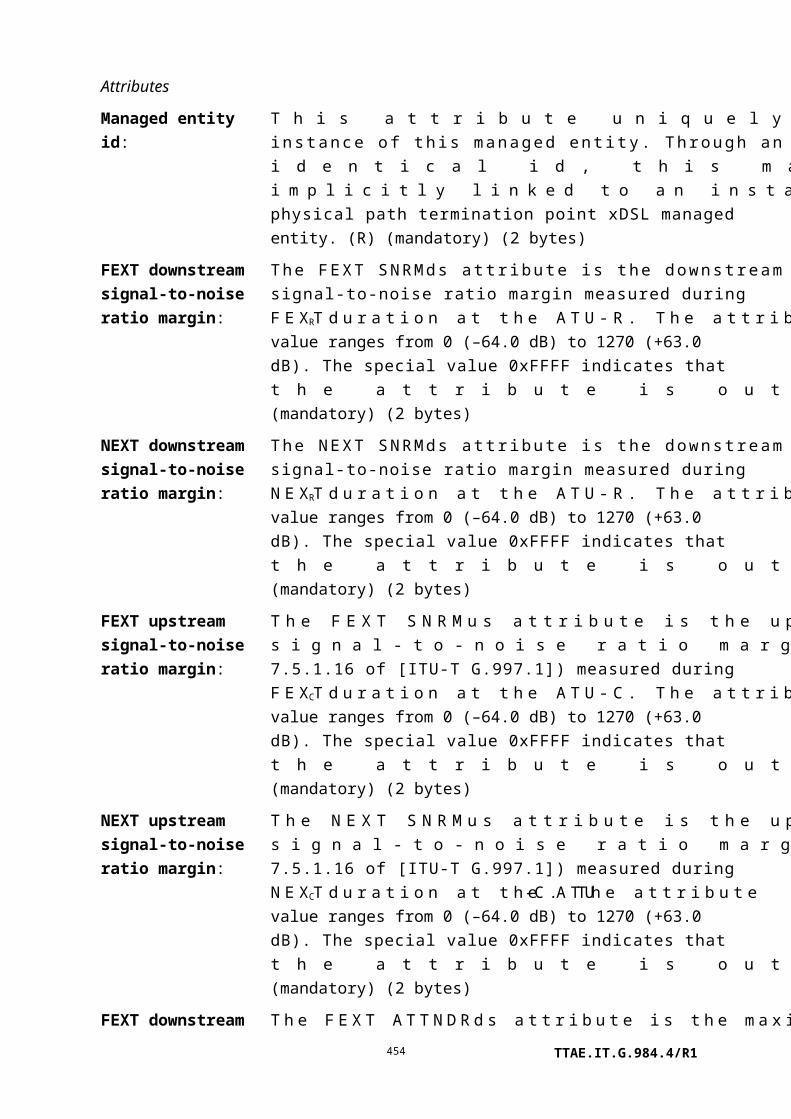
One or more instances of this managed entity are associated with the ONT-G managed entity to model the upstream priority queues if the traffic management option attribute in the ONT-G ME is 0 or 2.
One or more instances of this managed entity are associated with a physical path termination point UNI managed entity as downstream priority queues. Downstream priority queues may or may not be provided for a virtual Ethernet interface point.
Attributes
Managed entity id: This attribute uniquely identifies each instance of this managed entity. The most significant bit represents the direction (1: upstream, 0: downstream). The 15 least significant bits represent a queue id. The queue id is numbered in ascending order by the ONT itself. It is strongly encouraged that the queue id be formulated to simplify finding related queues. One way to do this is to number the queues such that the related port attributes are in ascending order (for the downstream and upstream queues separately). The range of downstream queue ids is 0 to 0x7FFF and the range of upstream queue ids is 0x8000 to 0xFFFF. (R) (mandatory) (2 bytes)
Queue configuration option:
This attribute identifies the buffer partitioning policy. The value 1 means that several queues share one buffer size of maximum queue size, while the value 0 means that each queue has an individual buffer of maximum queue size. (R) (mandatory) (1 byte)
Maximum queue size: This attribute specifies the maximum size of the queue. Units are GEM block lengths. (R) (mandatory) (2 bytes)
Allocated queue size: This attribute identifies the allocated size of this queue. Units are GEM block lengths. (R, W) (mandatory) (2 bytes)
Discard-block counter reset interval:
This attribute represents the interval in milliseconds at which the counter resets itself. (R, W) (optional) (2 bytes)
Threshold value for discarded blocks due to buffer overflow:
The threshold for the number of GEM block lengths discarded on this queue due to buffer overflow. (R, W) (optional) (2 bytes)
TTAE.IT.G.984.4/R1454

Related port: This attribute represents the slot, port/T-CONT and priority information associated with the instance of priority queue-G ME. This attribute comprises four bytes.
In the upstream direction, the first two bytes are the ME ID of the associated T-CONT, the first byte of which is a slot number, the second byte a T-CONT number. In the downstream direction, the first byte is the slot number and the second byte is the port number of the queue's destination port.
The last two bytes represent the priority of this queue. The range of priority is 0 to 0x0FFF. The value 0 indicates the highest priority and 0x0FFF indicates the lowest priority. (R, W) (mandatory) (4 bytes)
NOTE 1 – If flexible configuration is supported, the related port attribute is meaningful only if the traffic scheduler-G pointer attribute value is null. Otherwise, the related port attribute is ignored.
NOTE 2 – The related port attribute is read-only unless otherwise specified by the QoS configuration flexibility attribute of the ONT2-G managed entity. Even if flexibility is supported, only the second byte, the port or T-CONT number, may be changed. The OMCI set command must contain four bytes to match the attribute size, but the ONT must ignore all except the second byte.
If flexible configuration is not supported, the ONT should reject an attempt to set the related port with a parameter error result-reason code.
Traffic scheduler-G pointer:
This attribute points to the traffic scheduler-G ME instance that is associated with this priority queue. This pointer is used when this priority queue is connected with a traffic scheduler. The default value is null (0). (R, W) (mandatory) (2 bytes)
NOTE 3 – When the QoS configuration flexibility attribute of the ONT2-G managed entity allows flexible assignment of the traffic scheduler, the OLT may configure the traffic scheduler-G pointer to refer to any traffic scheduler in the same slot.
If traffic scheduler flexibility is not permitted by the QoS configuration flexibility attribute, the OLT may use the traffic scheduler-G pointer attribute only by pointing to another traffic
TTAE.IT.G.984.4/R1455

scheduler-G ME that is associated with the same T-CONT as the priority queue itself.
The ONT should reject an attempt to violate these conditions with a parameter error result-reason code.
Weight: This attribute represents weight for WRR. In the upstream direction, this weight is used by the traffic scheduler or T-CONT (whose policy is WRR) indicated by the traffic scheduler-G pointer attribute or related port attribute. Upon ME instantiation, the ONT sets this attribute to 1. (R, W) (mandatory) (1 byte)
Back pressure operation:
This attribute enables (0) or disables (1) back pressure operation. Its default value is 0. (R, W) (mandatory) (2 bytes)
Back pressure time: This attribute indicates the time for which the customer terminal temporarily suspends sending data. This attribute presents the duration in microseconds. This attribute can be used as a pause time for an Ethernet UNI. Values: 0 to 0xFFFF FFFF. Upon ME instantiation, the ONT sets this attribute to 0. (R, W) (mandatory) (4 bytes)
Back pressure occur queue threshold:
This attribute specifies the threshold queue occupancy, in GEM block lengths, to start sending back pressure signal. (R, W) (mandatory) (2 bytes)
Back pressure clear queue threshold:
This attribute specifies the threshold queue occupancy, in GEM block lengths, to stop sending back pressure signal. (R, W) (mandatory) (2 bytes)
Packet drop queue thresholds:
This attribute is a composite of four 2-byte values, a minimum and a maximum threshold, measured in GEM block lengths, for green and yellow packets. The first value is the minimum threshold, the queue occupancy below which all green packets are admitted to the queue. The second value is the maximum threshold, the queue occupancy at or above which all green packets are discarded. The third value is the minimum threshold, the queue occupancy below which all yellow packets are admitted to the queue. The fourth value is the maximum threshold, the queue occupancy at or above which all yellow packets are discarded. The default is that all thresholds take the value of the maximum queue size. (R, W) (optional) (8 bytes)
Packet drop max_p: This attribute is a composite of two 1-byte values, the probability of dropping a green or yellow packet when the queue
TTAE.IT.G.984.4/R1456

occupancy lies just below the max threshold. The first value is the green packet max_p, and the second value is the yellow packet max_p. The probability, max_p, is determined by adding one to the unsigned value (0..255) of this attribute and dividing the result by 256. The default for each value is 255. (R, W) (optional) (2 bytes)
Queue_drop_w_q: This attribute determines the averaging coefficient, w_q, as described in [b-Floyd]. The averaging coefficient, w_q, is equal to 2-Queue_drop_w_q. For example, when queue_drop_w_q has the value of 9, the averaging coefficient, w_q, is 0.0019. The default value is 9. (R, W) (optional) (1 byte)
Drop precedence colour marking:
This attribute specifies how the drop precedence is marked on the ingress packets to the priority queue. The default value is 0.
0 No marking (treat all packets as green)1 Internal marking (from traffic descriptor ME)2 DEI (802.1ad)3 PCP 8P0D (802.1ad)4 PCP 7P1D (802.1ad)5 PCP 6P2D (802.1ad)6 PCP 5P3D (802.1ad)7 DSCP AF class [b-IETF RFC 2597]
(R, W) (optional) (1 byte)
Actions
Get, set
Notifications
Alarm
Number Alarm Description
0 Block loss Content loss in excess of threshold. The alarm is
cleared when the discard block counter reset interval
next expires.
1..207 Reserved
208..223 Vendor-specific alarms Not to be standardized
9.11.2 Traffic scheduler-G
An instance of this managed entity represents a logical object that can control upstream GEM packets. A traffic scheduler can accommodate GEM packets after a priority queue or other
TTAE.IT.G.984.4/R1457
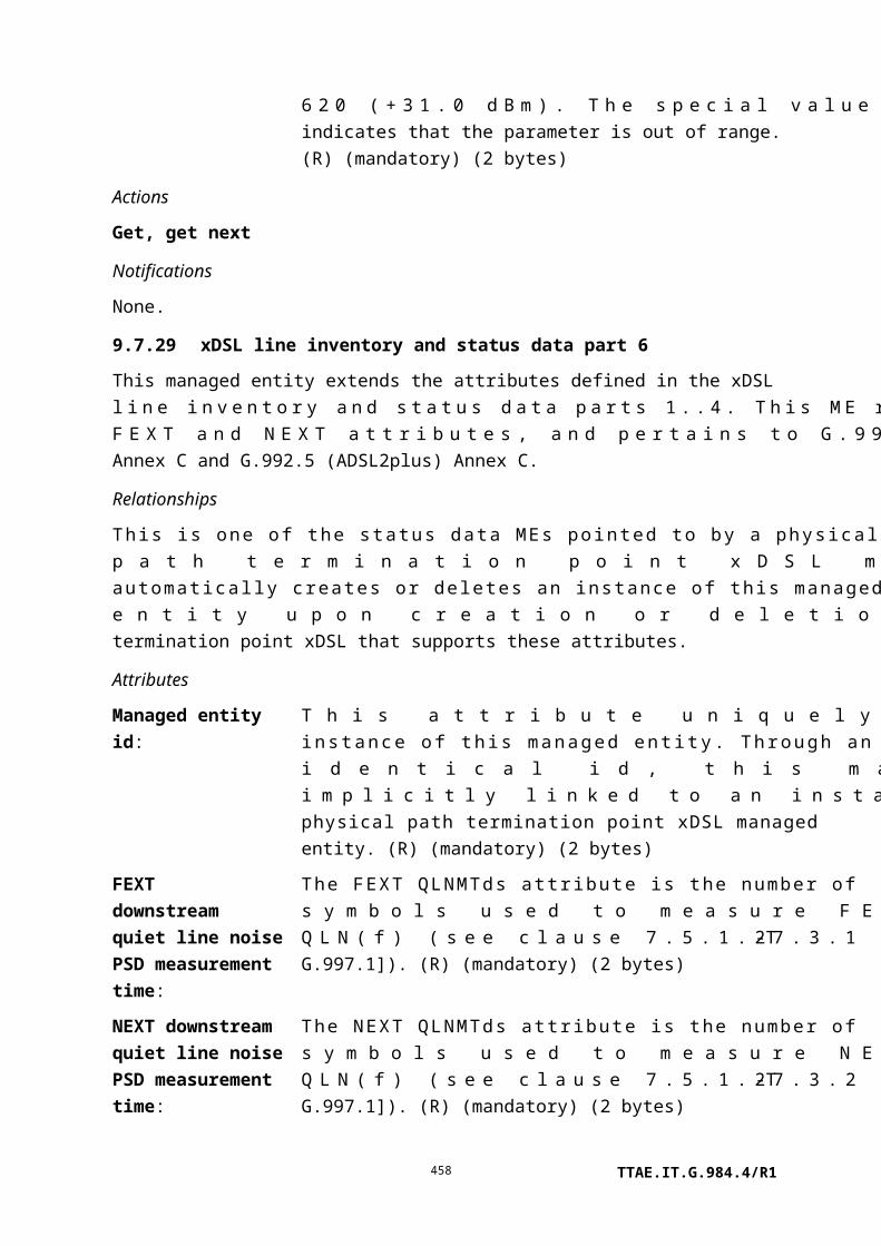
traffic scheduler and transfer them toward the next traffic scheduler or T-CONT. Because T-CONTs and traffic schedulers are created autonomously by the ONT, the ONT vendor predetermines the most complex traffic handling model it is prepared to support; the OLT may use less than the ONT's full capabilities, but cannot ask for more. See Appendix III for more detail.
After the ONT creates instances of T-CONT ME, it then autonomously creates instances of the traffic scheduler-G ME.
Relationships
The traffic scheduler-G ME may be related to a T-CONT or other traffic schedulers through pointer attributes.
Attributes
Managed entity id: This attribute uniquely identifies each instance of this managed entity. This two-byte number indicates the physical capability that realizes the traffic scheduler. The first byte is the slot id of the circuit pack with which this traffic scheduler is associated. For a traffic scheduler that is not associated with a circuit pack, the first byte is 0xFF. The second byte is the traffic scheduler id, assigned by the ONT itself. Traffic scheduler ids are numbered in ascending order with range 0..0xFF in each circuit pack or ONT core. (R) (mandatory) (2 bytes)
T-CONT pointer: This attribute points to the T-CONT ME instance associated with this traffic scheduler. This pointer is used when this traffic scheduler is connected to the T-CONT directly. It is null (0) otherwise. (R, W) (mandatory) (2 bytes)
NOTE – This attribute is read-only, unless otherwise specified by the QoS configuration flexibility attribute of the ONT2-G managed entity. If flexible configuration is not supported, the ONT should reject an attempt to set the T-CONT pointer attribute with a parameter error result-reason code.
Traffic scheduler pointer:
This attribute points to another traffic scheduler-G ME instance that may serve this traffic scheduler. This pointer is used when this traffic scheduler is connected to another traffic scheduler; it is null (0) otherwise. (R) (mandatory) (2 bytes)
Policy: This attribute represents scheduling policy. Valid values include:
0 Null1 HOL (head of line)
TTAE.IT.G.984.4/R1458

2 WRR (weighted round robin)
(R, W) (mandatory) (1 byte)
NOTE 2 – This attribute is read-only, unless otherwise specified by the QoS configuration flexibility attribute of the ONT2-G managed entity. If flexible configuration is not supported, the ONT should reject an attempt to set the policy attribute with a parameter error result-reason code.
Priority/weight: This attribute represents priority for HOL scheduling or the weight for WRR scheduling. This value is used by the T-CONT or traffic scheduler indicated by the T-CONT pointer attribute or traffic scheduler pointer attribute. If the indicated pointer has policy = HOL, this value is interpreted as a priority (0 is the highest priority, 255 the lowest). If the indicated pointer has policy = WRR, this value is interpreted as a weight. Upon ME instantiation, the ONT sets this attribute to 0. (R, W) (mandatory) (1 byte)
Actions
Get, set
Notifications
None.
9.11.3 GEM traffic descriptor
The traffic descriptor allows for traffic management. A priority controlled ONT can point from a MAC bridge port configuration data ME to a traffic descriptor in order to implement traffic management (marking, policing). A rate controlled ONT can point to a traffic descriptor from either a MAC bridge port configuration data ME or GEM port network CTP to implement traffic management (marking, shaping).
Packets are determined to be green, yellow or red as a function of the ingress packet rate and the settings in this ME. The colour indicates drop precedence (eligibility), subsequently used by the priority queue-G ME to drop packets conditionally during congestion conditions. Packet colour is also used by the mode 1 DBA status reporting function described in [ITU-T G.984.3]. Red packets are dropped immediately. Yellow packets are marked as drop eligible, and green packets are marked as not drop eligible, according to the egress colour marking attribute.
The algorithm used to determine the colour marking is specified by the meter type attribute. If [b-IETF RFC 4115] is used, then
TTAE.IT.G.984.4/R1459

CIR4115 = CIR
EIR4115 = PIR – CIR (EIR: excess information rate)
CBS4115 = CBS
EBS4115 = PBS – CBS.
Relationships
This ME is associated with a GEM port network CTP or a MAC bridge port configuration data managed entity.
Attributes
Managed entity id: This attribute uniquely identifies each instance of this managed entity. (R, Set-by-create) (mandatory) (2 bytes)
CIR This attribute specifies committed information rate, in byte/s. The default is 0. (R, W, Set-by-create) (optional) (4 bytes)
PIR: This attribute specifies peak information rate, in byte/s. The default value 0 accepts the ONT's factory policy. (R, W, Set-by-create) (optional) (4 bytes)
CBS: This attribute specifies committed block size, in bytes. The default is 0. (R, W, Set-by-create) (optional) (4 bytes)
PBS: This attribute specifies peak block size, in bytes. The default value 0 accepts the ONT's factory policy. (R, W, Set-by-create) (optional) (4 bytes)
Colour mode: This attribute specifies whether the colour marking algorithm considers pre-existing marking on ingress packets (colour-aware) or ignores it (colour-blind). If colour-aware, packets can only be demoted (from green to yellow or red, or from yellow to red). The default value is 0.
0 Colour-blind1 Colour-aware
(R, W, Set-by-create) (optional) (1 byte)
Ingress colour marking:
This attribute is meaningful in colour-aware mode. It specifies how the pre-existing drop precedence is marked on ingress packets. For DEI and PCP marking, a drop eligible indicator is equivalent to yellow colour; otherwise, the colour is green. For DSCP AF marking, the lowest drop precedence is equivalent to green; otherwise, the colour is yellow. The default value is 0.
TTAE.IT.G.984.4/R1460

0 No marking (ignore ingress marking)2 DEI (802.1ad)3 PCP 8P0D (802.1ad)4 PCP 7P1D (802.1ad)5 PCP 6P2D (802.1ad)6 PCP 5P3D (802.1ad)7 DSCP AF class [b-IETF RFC 2597]
(R, W, Set-by-create) (optional) (1 byte)
Egress colour marking:
This attribute specifies how drop precedence is to be marked by the ONT on egress packets. If set to internal marking only, the externally visible packet contents are not modified, but the packet is identified in a vendor-specific local way that indicates its colour to the priority queue-G ME. It is possible for the egress marking to differ from the ingress marking; for example, ingress PCP marking could be translated to DEI egress marking. The default value is 0.
0 No marking1 Internal marking only2 DEI (802.1ad)3 PCP 8P0D (802.1ad)4 PCP 7P1D (802.1ad)5 PCP 6P2D (802.1ad)6 PCP 5P3D (802.1ad)7 DSCP AF class [b-IETF RFC 2597]
(R, W, Set-by-create) (optional) (1 byte)
Meter type: This attribute specifies the algorithm used to determine the colour of the packet. The default value is 0.
0 Not specified1 [b-IETF RFC 4115]2 [b-IETF RFC 2698]
(R, Set-by-create) (optional) (1 byte)
Actions
Create, delete, get, set
Notifications
None.
TTAE.IT.G.984.4/R1461

9.12 General purpose MEs
9.12.1 UNI-G
This managed entity organizes data associated with user network interfaces (UNIs) supported by GEM. One instance of the UNI-G managed entity exists for each UNI supported by the ONT.
The ONT automatically creates or deletes instances of this managed entity upon the creation or deletion of a real or virtual circuit pack managed entity, one per port.
Relationships
An instance of the UNI-G managed entity exists for each instance of a physical path termination point managed entity.
Attributes
Managed entity id: This attribute uniquely identifies each instance of this managed entity. Through an identical ID, this managed entity is implicitly linked to an instance of a physical path termination point. (R) (mandatory) (2 bytes)
Configuration option status:
This attribute holds the UNI configuration code field. Its bits are assigned as shown below.
Bit Name Setting
1 N/A
2 Server trail fault
propagation TC layer
0: All TC layer alarm reporting through the OMCC is
inhibited. 1: TC layer alarm reporting through the OMCC
is not inhibited.
3 Server trail fault
propagation PHY layer
0: All PHY layer alarm reporting through the OMCC is
inhibited. 1: PHY layer alarm reporting through the
OMCC is not inhibited.
4 Server trail fault
propagation GAL layer
0: All GAL layer alarm reporting through the OMCC is
inhibited. 1: GAL layer alarm reporting through the
OMCC is not inhibited.
5..16 Reserved
(R, W) (mandatory) (2 bytes)
Administrative state: This attribute locks (1) and unlocks (0) the functions performed by this managed entity. When the administrative state is set to lock, all user functions of this managed entity are blocked, and alarms, TCAs and AVCs for this managed entity and all
TTAE.IT.G.984.4/R1462

dependent managed entities are no longer generated. Selection of a default value for this attribute is outside the scope of this Recommendation. (R, W) (mandatory) (1 byte)
NOTE – PPTP MEs also have an administrative state attribute. The
user port is unlocked only if both administrative state attributes are set
to unlocked.
Non-OMCI management identifier:
If a PPTP can be managed either directly by OMCI or a non-OMCI management environment, this attribute specifies how it is in fact to be managed. This attribute is either 0 (default = OMCI management), or it is a pointer to a virtual Ethernet interface point, which in turn links to a non-OMCI management environment. (R, W) (optional) (2 bytes)
Actions
Get, set
Notifications
None.
9.12.2 OLT-G
NOTE – Except for its name, this managed entity is identical to the OLTB-PON ME documented in [ITU-T G.983.2].
This optional managed entity identifies the OLT to which an ONT is connected. This ME provides a way for the ONT to configure itself for operability with a particular OLT.
An ONT that supports this managed entity automatically creates an instance of it. Immediately following the startup phase, the OLT should set the ONT to the desired configuration. Interpretation of the attributes is a matter for negotiation between the two vendors involved.
Relationships
One instance of this managed entity is associated with the ONT managed entity.
Attributes
TTAE.IT.G.984.4/R1463

Managed entity id: This attribute uniquely identifies each instance of this managed entity. There is only one instance, number 0. (R) (mandatory) (2 bytes)
OLT vendor id: This attribute identifies the OLT vendor. It is the same as the 4 most significant bytes of an ONT serial number specified in [ITU-T G.984.3]. Upon instantiation, this attribute comprises all spaces. (R, W) (mandatory) (4 bytes)
Equipment id: This attribute may be used to identify the specific type of OLT. The default value of all spaces indicates that equipment ID information is not available or applicable to the OLT being represented. (R, W) (mandatory) (20 bytes)
Version: This attribute identifies the version of the OLT as defined by the vendor. The default left-justified ASCII string "0" (padded with trailing nulls) indicates that version information is not available or applicable to the OLT being represented. (R, W) (mandatory) (14 bytes)
Time of day information:
This attribute provides the information required to achieve time of day synchronization between a reference clock at the OLT and a local clock at the ONT. This attribute comprises two fields: the first field (4 bytes) is the sequence number of the specified GEM superframe. The second field (10 bytes) is TstampN as defined in clause 10.4.6.1 of [ITU-T G.984.3], using the timestamp format of IEEE 1588-2008, clause 5.3.3. The value 0 in all bytes is reserved as a null value. (R, W) (optional) (14 bytes)
Actions
Get, set
Notifications
None.
9.12.3 Network address
The network address managed entity associates a network address with security methods required to access a server. It is conditionally required for ONTs that support VoIP service. The address may take the form of a URI, a fully qualified path or IP address represented as an ACII string.
TTAE.IT.G.984.4/R1464

If a non-OMCI interface is used to manage VoIP signalling, this ME is unnecessary. The non-OMCI interface supplies the necessary data, which may be read back to the OLT via the SIP config portal ME or the MGC config portal ME.
Instances of this managed entity are created and deleted by the OLT or the ONT depending on the method used and case.
Relationships
Any managed entity that requires a network address may link to an instance of this ME.
Attributes
Managed entity id: This attribute uniquely identifies each instance of this managed entity. Instances of this managed entity created autonomously by the ONT have IDs in the range 0..0x7FFF. Instances created by the OLT have IDs in the range 0x8000..0xFFFE. The value 0xFFFF is not valid. (R, Set-by-create) (mandatory) (2 bytes)
Security pointer: If this attribute is set to its default value 0xFFFF, security attributes are not defined for this network address. If this attribute is set to any other value, it points to an authentication security method managed entity. The authentication security method indicates the username and password to be used when retrieving the network address indicated by this ME. (R, W, Set-by-create) (mandatory) (2 bytes)
Address pointer: This attribute points to the large string ME that contains the network address. It may contain a fully qualified domain name, URI or IP address. The URI may also contain an optional port identifier (e.g., "x.y.z.com:5060"). The default value 0xFFFF indicates that no network address is defined. (R, W, Set-by-create) (mandatory) (2 bytes).
Actions
Create, delete, get, set
Notifications
None.
9.12.4 Authentication security method
The authentication security method defines the user id/password configuration to establish a session between a client and server. This object may be used in the role of the client or server. An instance of this managed entity is created by the OLT if authenticated communication is necessary.
TTAE.IT.G.984.4/R1465

Relationships
One instance of this management entity may be associated with a network address ME. This ME may also be cited by other MEs that require authentication parameter management.
Attributes
Managed entity id: This attribute uniquely identifies each instance of this managed entity. The value 0xFFFF is not valid. (R, Set-by-create) (mandatory) (2 bytes)
Validation scheme: This attribute specifies the validation scheme used when the ONT validates a challenge. Validation schemes are defined as follows:
…
1 Validate using MD5 digest authentication as defined in [IETF RFC 2617] (recommended)
Username 1: This string attribute is the user name. If the string is shorter than 25 bytes, it must be null terminated (Note). (R, W) (mandatory) (25 bytes)
Password: This string attribute is the password. If the string is shorter than 25 bytes, it must be null terminated. (R, W) (mandatory) (25 bytes)
Realm: This string attribute specifies the realm used in digest authentication. If the string is shorter than 25 bytes, it must be null terminated. (R, W) (mandatory) (25 bytes)
Username 2: This string attribute allows for continuation of the user name beyond 25 characters (Note). Its default value is a null string. (R, W) (optional) (25 bytes)
NOTE The total username is the concatenation of the username 1 and username 2 attributes if and only if a) username 1 comprises 25 non-null characters, b) username 2 is supported by the ONT, and c) username 2 contains a leading non-null character string. Otherwise, the total username is simply the value of the username 1 attribute.
Actions
Create, delete, get, set
Notifications
None.
TTAE.IT.G.984.4/R1466

9.12.5 Large string
The large string managed entity holds strings longer than 25 bytes, up to 375 bytes. It is maintained in up to 15 parts, each part containing 25 bytes. If the final part contains fewer than 25 bytes, it is terminated by at least one null byte. For example:
Number of parts 3
Part 1 sftp://myusername:mypassw
Part 2 [email protected]:12
Part 3 34/path/to/filename<null>
OrNumber of parts 3
Part 1 sftp://myusername:mypassw
Part 2 [email protected]:12
Part 3 34/path/to/longfilename<null>
Instances of this managed entity are created and deleted by the OLT. To use this managed entity, the OLT instantiates the large string ME and then points to the created ME from other ME instances. Systems that maintain the large string should ensure that the large string ME is not deleted while it is still linked.
Relationships
An instance of this ME may be cited by any ME that requires a text string longer than 25 bytes.
Attributes
Managed entity id: This attribute uniquely identifies each instance of this managed entity. The value 0xFFFF is not valid. (R, Set-by-create) (mandatory) (2 bytes)
Number of parts: This attribute specifies the number of non-empty parts that form the large string. This attribute defaults to 0 to indicate no large string is defined. (R, W) (mandatory) (1 byte).
Fifteen additional attributes are defined below; they are identical. The large string is simply divided into as many parts as necessary, starting at part 1. If the end of the string does not lie at a part boundary, it is marked with a null byte.
Part 1, Part 2, Part 3, Part 4, Part 5, Part 6, Part 7, Part 8, Part 9, Part 10, Part 11, Part 12, Part 13, Part 14, Part 15: (R, W) (mandatory) (25 bytes * 15 attributes)
Actions
TTAE.IT.G.984.4/R1467
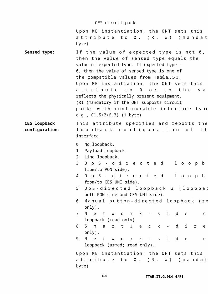
Create, delete, get, set
Notifications
None.
9.12.6 Threshold data 1
Threshold data is partitioned into two MEs to permit the set-by-create operation on all attributes, as limited by OMCI message size. An instance of this managed entity, together with an optional instance of the threshold data 2 ME, contains threshold values for performance monitoring counters in history data managed entities.
For a complete discussion of generic PM architecture, refer to clause I.1.9.
Instances of this managed entity are created and deleted by the OLT.
Relationships
Managed entities that support PM functionality are listed in clause 7.3.
Paired instances of threshold data 1 ME and threshold data 2 ME are implicitly linked together through a common ME ID.
Attributes
Managed entity id: This attribute uniquely identifies each instance of this managed entity. (R, Set-by-create) (mandatory) (2 bytes)
The following seven attributes specify threshold values for seven thresholded counters in associated PM history data MEs. The definition of each PM history ME includes a table that links each thresholded counter to one of these threshold value attributes.
Threshold value 1: (R, W, Set-by-create) (mandatory) (4 bytes)
Threshold value 2: (R, W, Set-by-create) (mandatory) (4 bytes)
Threshold value 3: (R, W, Set-by-create) (mandatory) (4 bytes)
Threshold value 4: (R, W, Set-by-create) (mandatory) (4 bytes)
Threshold value 5: (R, W, Set-by-create) (mandatory) (4 bytes)
Threshold value 6: (R, W, Set-by-create) (mandatory) (4 bytes)
Threshold value 7: (R, W, Set-by-create) (mandatory) (4 bytes)
Actions
Create, delete, get, set
Notifications
None.
TTAE.IT.G.984.4/R1468

9.12.7 Threshold data 2
Together with an instance of the threshold data 1 ME, an instance of this managed entity contains threshold values for the performance monitoring parameters maintained in one or more instances of history data managed entities.
For a complete discussion of generic PM architecture, refer to clause I.1.9.
Instances of this managed entity are created and deleted by the OLT.
Relationships
Refer to the relationships of the threshold data 1 ME.
Attributes
Managed entity id: This attribute uniquely identifies each instance of this managed entity. Its value is the same as that of the paired threshold data 1 instance. (R, Set-by-create) (mandatory) (2 bytes)
The following seven attributes specify threshold values for seven thresholded counters in associated PM history data MEs. The definition of each PM history ME includes a table that links each thresholded counter to one of these threshold value attributes.
Threshold value 8: (R, W, Set-by-create) (mandatory) (4 bytes)
Threshold value 9: (R, W, Set-by-create) (mandatory) (4 bytes)
Threshold value 10: (R, W, Set-by-create) (mandatory) (4 bytes)
Threshold value 11: (R, W, Set-by-create) (mandatory) (4 bytes)
Threshold value 12: (R, W, Set-by-create) (mandatory) (4 bytes)
Threshold value 13: (R, W, Set-by-create) (mandatory) (4 bytes)
Threshold value 14: (R, W, Set-by-create) (mandatory) (4 bytes)
Actions
Create, delete, get, set
Notifications
None.
9.12.8 OMCI
This managed entity describes the ONT's general level of support for OMCI managed entities and messages. This ME is not included in MIB upload.
Relationships
One instance exists in the ONT. The ME entities are related to the OMCI entity.
TTAE.IT.G.984.4/R1469

Attributes
Managed entity id: This attribute uniquely identifies each instance of this managed entity. There is only one instance, number 0. (R) (mandatory) (2 bytes)
ME type table: This attribute lists the ME classes supported by the ONT. Each entry contains the managed entity class value (see Table 11-2) of a managed entity. For MEs inherited from G.983.2 B-PON, the most significant byte is zero. (R) (mandatory) (2N bytes, where N is the number of entries in the list)
Message type table: This attribute is a list of message types supported by the ONT. Each entry contains the message type of an OMCI message (see Table 11-1). (R) (mandatory) (M bytes, where M is the number of entries in the list)
Actions
Get, get next
Notifications
None.
9.12.9 Managed entity
The managed entity ME describes the details of each managed entity that is supported by the ONT. This ME is not included in MIB upload.
Relationships
One or more managed entity entities are related to the OMCI object entity.
Attributes
Managed entity id: This attribute uniquely identifies each instance of this managed entity. Its value is equal to the managed entity type value, and is the same as the code found in the ME type table attribute of the OMCI ME and Table 11-2. (R) (mandatory) (2 bytes)
Name: This attribute contains a 25-byte ASCII coded mnemonic tag for the ME type. Strings shorter than 25 bytes are padded with null characters. (R) (mandatory) (25 bytes)
Attributes table: This table contains pointers to the attribute MEs that describe each of these ME's attributes.
NOTE – The managed entity ID attribute is not included in the list, since the type of this attribute is fixed.
TTAE.IT.G.984.4/R1470

(R) (mandatory) (2X bytes, where X is the number of entries in the table)
Access: This attribute represents who creates this ME. The following code points are defined:
1 Created by the ONT.2 Created by the OLT.3 Created by both ONT and OLT.
(R) (mandatory) (1 byte)
Alarms table: This attribute lists the alarm codes that are supported. (R) (mandatory) (Y bytes, where Y is the number of entries in the table)
AVCs table: This attribute lists the AVCs that are supported. (R) (mandatory) (Z bytes, where Z is the number of entries in the table)
Actions: This attribute lists the action codes supported on this object, formatted as a bit map. The action codes are the message types from Table 11-1. The least significant bit represents action 0, and so on. (R) (mandatory) (4 bytes)
Instances table: This attribute is a list of pointers to all instances of this ME. (R) (mandatory) (2V bytes, where V is the number of entries in the table)
Support: This attribute represents support capability of this ME in the ONT's implementation. This attribute does not declare if the OMCI implementation complies with the recommendations, but if it complies with the OMCI declaration itself. The following code points are defined:
1 Supported (supported as defined in this object).2 Unsupported (OMCI returns error code if accessed).3 Partially supported (some aspects of ME supported).4 Ignored (OMCI supported, but underlying function is not).
(R) (mandatory) (1 byte)
Actions
Get, get next
Notifications
None.
TTAE.IT.G.984.4/R1471
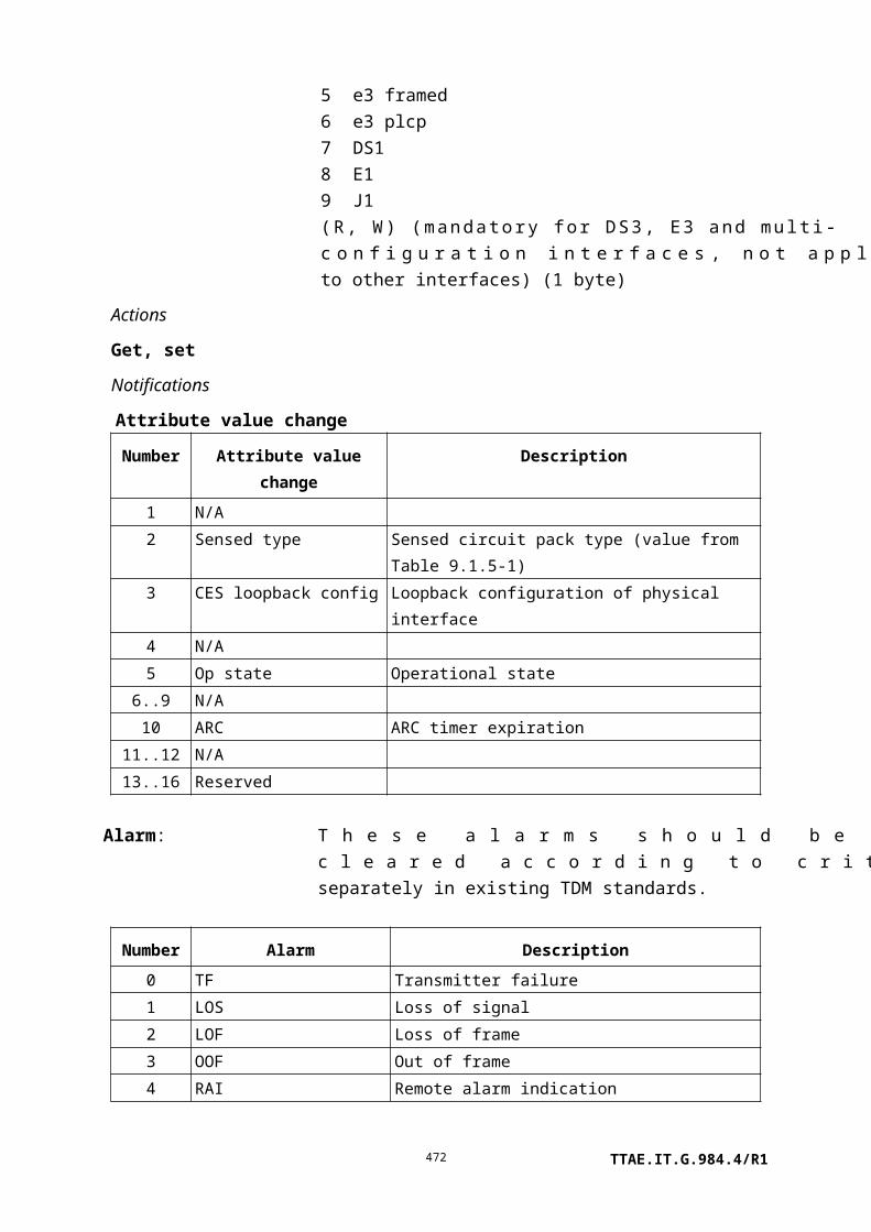
9.12.10 Attribute
This managed entity describes a particular attribute type that is supported by the ONT. This ME is not included in MIB upload.
Relationships
One or more attribute entities are related to each ME entity. More than one ME entity can refer to a given attribute entity.
Attributes
Managed entity id: This attribute uniquely identifies each instance of this managed entity. This number is the same that appears in the attributes table in the managed entity ME. Only one instance of each unique attribute need be created. The ONT can assign attribute numbering as it pleases, out of the pool of 64K ids; however, it is suggested that the numbering follow a rational scheme to aid human readability. (R) (mandatory) (2 bytes)
Name: This attribute contains a 25-byte mnemonic tag for the attribute. Strings shorter than 25 bytes are padded with null characters. (R) (mandatory) (25 bytes)
Size: This attribute contains the size of the attribute, in bytes. The value 0 indicates that the attribute can have a variable/unknown size. (R) (mandatory) (2 bytes)
Access: This attribute represents the OMCI access characteristics of the attribute. The following code points are defined:
1 Read.2 Write.3 Read, write.5 Read, Set-by-create.6 Write, Set-by-create.7 Read, write, Set-by-create.
(R) (mandatory) (1 byte)
Format: This attribute represents the format of the attribute. The following code points are defined:
1 Pointer.2 Bit field.3 Signed integer.4 Unsigned integer.5 String.
TTAE.IT.G.984.4/R1472

6 Enumeration (that is, a set of defined code points).7 Table.
(R) (mandatory) (1 byte)
Lower limit: This attribute provides the lowest value for the attribute. Valid for numeric types (pointer, signed integer, unsigned integer) only. For attributes smaller than 4 bytes, the desired numeric value is expressed in 4-byte representation (e.g., the signed one-byte integer 0xFE is expressed as 0xFFFF FFFE; the unsigned one-byte integer 0xFE is expressed as 0x0000 00FE). (R) (mandatory) (4 bytes)
Upper limit: This attribute provides the highest value for the attribute. It has the same validity and format as the lower limit attribute. (R) (mandatory) (4 bytes)
Bit field: This attribute is a mask of the supported bits in a bit field attribute. Valid for bit field type only. A 1 in any position signifies that its code point is supported, while 0 indicates not supported. For bit fields smaller than 4 bytes, the attribute is aligned at the least significant end of the mask. (R) (mandatory) (4 bytes)
Code points table: This attribute lists the code points supported by an enumerated attribute. (R) (mandatory) (2Q bytes, where Q is the number of entries in the table)
Support: This attribute represents the level of support of the attribute (same notation as the attribute of the same name in the ME). The following code points are defined:
1 Fully supported (supported as defined in this object).2 Unsupported (OMCI returns an error code if accessed).3 Partially supported (some aspects of attribute supported).4 Ignored (OMCI supported, but underlying function is not).
(R) (mandatory) (1 byte)
Actions
Get, get next
Notifications
None.
TTAE.IT.G.984.4/R1473
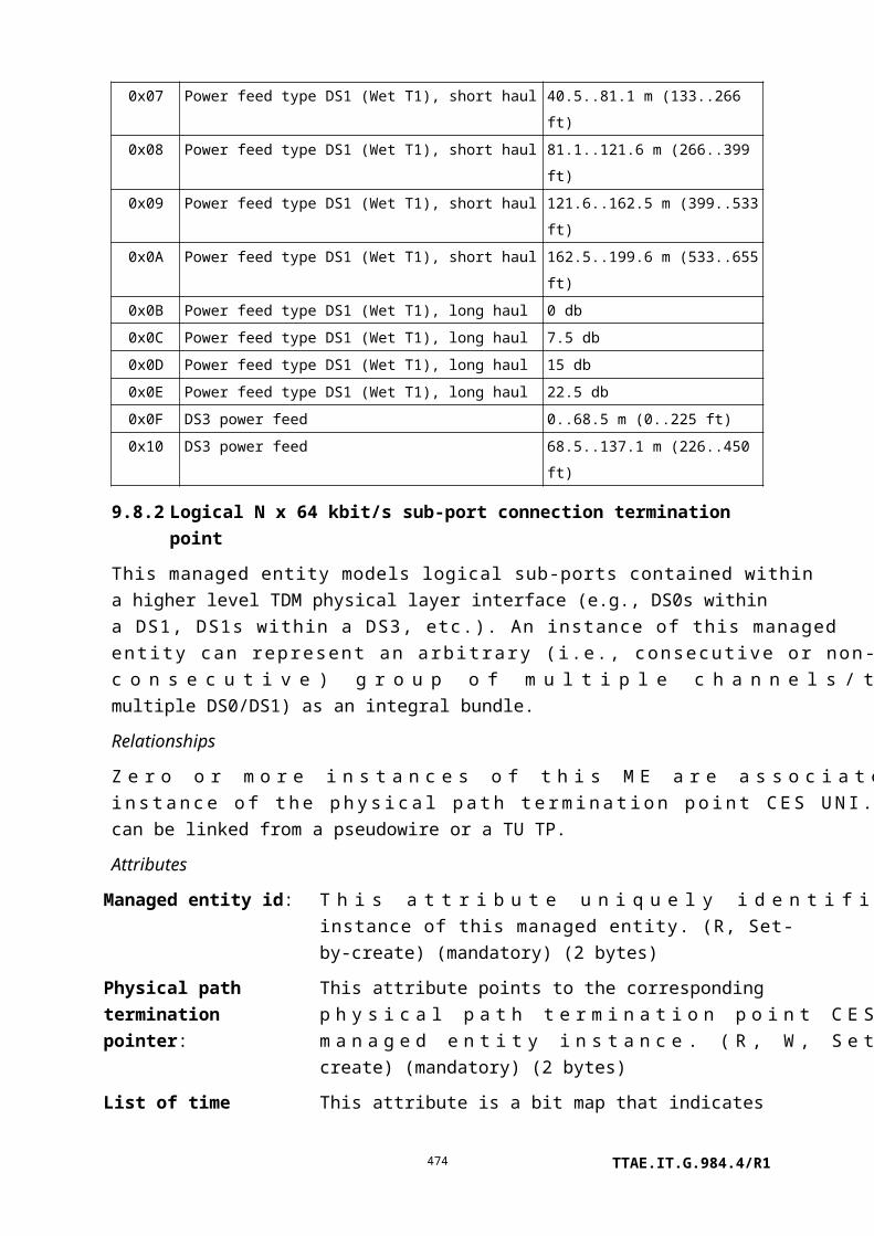
9.12.11 Octet string
The octet string is modelled on the large string managed entity. The large string is constrained to printable characters because it uses null as a trailing delimiter. The octet string has a length attribute and is therefore suitable for arbitrary sequences of bytes.
Instances of this managed entity are created and deleted by the OLT. To use this managed entity, the OLT instantiates the octet string ME and then points to the created ME from other ME instances. Systems that maintain the octet string should ensure that the octet string ME is not deleted while it is still linked.
Relationships
An instance of this ME may be cited by any ME that requires an octet string that can exceed 25 bytes in length.
Attributes
Managed entity id: This attribute uniquely identifies each instance of this managed entity. The values 0 and 0xFFFF are reserved. (R, Set-by-create) (mandatory) (2 bytes)
Length: This attribute specifies the number of octets that comprise the sequence of octets. This attribute defaults to 0 to indicate no octet string is defined. The maximum value of this attribute is 375 (15 parts, 25 bytes each). (R, W) (mandatory) (2 bytes)
Fifteen additional attributes are defined below; they are identical. The octet string is simply divided into as many parts as necessary, starting at part 1 and left justified.
Part 1, Part 2, Part 3, Part 4, Part 5, Part 6, Part 7, Part 8, Part 9, Part 10, Part 11, Part 12, Part 13, Part 14, Part 15: (R, W) (part 1 mandatory, others optional) (25 bytes * 15 attributes)
Actions
Create, delete, get, set
Notifications
None.
9.12.12 General purpose buffer
This managed entity is created by the OLT when needed to store the results of an operation, such as a test command, that needs to return a block of data of indeterminate size. The buffer is retrieved with get next operations, since its size is not known a priori. An instance of this ME is created and deleted by the OLT, and typically made known to an ONT ME or action through a pointer.
TTAE.IT.G.984.4/R1474

The ME is defined as generically as possible, such that it can be used for other applications that may not initially be apparent, such as logging. The format of its contents is specific to each application, and is documented there.
The general purpose buffer is neither captured in a MIB upload, nor retained in non-volatile ONT memory.
Relationships
Through a pointer, the OLT may associate a general purpose buffer with an ME and/or an operation that has a need to create large or indeterminate blocks of data for subsequent upload.
Attributes
Managed entity id: This attribute uniquely identifies each instance of this managed entity. (R, Set-by-create) (mandatory) (2 bytes)
Maximum size: The ONT determines the actual size of the buffer table in the process of capturing the data directed to it. The maximum size attribute permits the OLT to restrict the maximum size of the buffer table. The default value 0 indicates that the OLT imposes no limit on the size; it is recognized that ONT implementations will impose their own limits. The ONT will not create a buffer table larger than this value. If the ONT cannot allocate enough memory to accommodate this size, it should deny the ME creation action or a write operation that attempts to expand an existing ME. (R, W, Set-by-create) (optional) (4 bytes)
Buffer table: This attribute is an octet string that contains the result of some operation performed on the ONT. The exact content depends on the operation, and is documented with the definition of each operation. (R) (mandatory) (N bytes)
Actions
Create, delete, get, get next
Notifications
Attribute value change
Number Attribute value change Description
TTAE.IT.G.984.4/R1475

1 Reserved
2 Buffer table
This AVC indicates that the ONT has completed
writing the buffer, and thereby signals the OLT that
the operation is complete and the buffer is available
for upload
3..16 Reserved
9.12.13 File transfer controller
This optional managed entity allows file transfers to be conducted out of band. It is intended to facilitate software image download, but may be extended for other file transfer applications as well.
Relationships
One instance of this managed entity exists in an ONT that supports out of band file transfer.
Attributes
Managed entity id: This attribute uniquely identifies each instance of this managed entity. There is one instance, whose value is 0. (R) (mandatory) (2 bytes)
Supported transfer protocols:
This attribute is a bit map. Each bit indicates that the corresponding protocol is (1) or is not (0) supported for file transfers. TFTP is mandatory; the other protocols are optional. (R) (mandatory) (2 bytes)
Bit Protocol
1 (LSB) FTP2 TFTP3 SFTP4 HTTP5 HTTPS6 FLUTE ([b-IETF RFC 3926]; multicast, download
only)7 DSM-CC (multicast, download only)8..12 Reserved13..16 Vendor-specific use; not to be standardized
File type: This attribute specifies the owner managed entity type of the file to be transferred. It is a value from Table 11-2. For example, for software image download, this attribute has the value 7. File systems on circuit packs are identified with the value 6, and on the
TTAE.IT.G.984.4/R1476

ONT-G as a whole with the value 256. (R, W) (mandatory) (2 bytes)
File instance: This attribute specifies the instance of the file to be transferred. This attribute is the same as the ME ID attribute of the owner ME. (R, W) (mandatory) (2 bytes)
Local file name pointer:
This attribute designates a large string ME that specifies a local file name. Since naming is not specified for any OMCI files, this attribute should be a null pointer in standard OMCI usage, for example, in the software image case. The use of this attribute for named files is vendor-specific. (R, W) (mandatory) (2 bytes)
Network address pointer:
This attribute is a pointer to a network address ME that specifies optional authentication information, along with the URI to be used for the file transfer. The URI should specify the protocol, one from the list of protocols supported by the ONT, an IP address or a string that can be resolved into an IP address, and optionally a port. For unidirectional multicast download (e.g., DSM-CC), the URI should specify a multicast IP source address. (R, W) (mandatory) (2 bytes)
File transfer trigger: This attribute causes the file transfer to begin. If a given set operation writes values to several attributes of this managed entity, the ONT should apply the file transfer trigger after updating all other attributes. Some operations may not be applicable to some files; the ONT should deny commands that request unsupported actions. (R, W) (mandatory) (1 byte)
Value Meaning
0 Reserved1 Initiate file download (to the ONT)2 Initiate file upload (from the ONT)3 Abort current file transfer4 Delete target file5 Perform a directory listing operation. The scope of the
directory is not specified; at the vendor's option, the listing may be filtered by matching some or all of file type, file instance and local file name attributes.
6..255 Reserved
File transfer status: This attribute reports the status of a file transfer. (R) (mandatory) (1 byte)
TTAE.IT.G.984.4/R1477

Value Meaning
0 File transfer completed successfully1 File transfer aborted successfully2 File deleted3 URL undefined or unreachable4 Failure to authenticate5 File transfer in progress6 Remote failure7 Local failure8..255 Reserved
GEM IWTP pointer: This attribute is a pointer that specifies a unicast or multicast GEM interworking termination point, depending on whether the transfer protocol to be used is unicast or multicast. (R, W) (optional) (2 bytes)
VLAN: This attribute specifies the VLAN to be used for the transfer, assuming multicast protocol. The default value 0 indicates that no VLAN is specified. (R, W) (optional) (2 bytes)
File size: This attribute allows the OLT to specify the size of a file to be downloaded, in bytes. The ONT may use this value to reserve memory or to deny the download command if it has insufficient space. The default value 0 does not specify a file size. (R, W) (optional) (4 bytes)
Actions
Get, set
Notifications
Attribute value change
Number Attribute value change Description
1..6 N/A
7 File transfer status
8..10 Reserved
11 Directory listing table This AVC signals the OLT that a directory listing operation
is complete and may be retrieved with a get, get next
sequence.
12..16 Reserved
TTAE.IT.G.984.4/R1478

9.12.14 Generic status portal
The generic status portal managed entity provides a way for the OLT to discover the status and configuration information of a non-OMCI management domain within an ONT. The non-OMCI management domain is indicated by the virtual Ethernet interface point associated with this generic status portal.
The generic status portal ME uses two table attributes to convey status and configuration from a non-OMCI managed domain to OMCI. Each of these attributes uses an XML document to present this information. These XML documents are not required to be understood by the OLT or EMS. The schema for the documents may be used in the creation of tools that parse and interpret the contents of the document.
Relationships
One instance of this ME is created by the OLT for each separate non-OMCI management domain whose information is desired to be visible.
Attributes
Managed entity ID: This attribute uniquely identifies each instance of this managed entity. Through an identical ID, the generic status portal ME is implicitly linked to an instance of the virtual Ethernet interface point ME. (R, Set-by-create) (mandatory) (2 bytes). (R)
Status document table:
This attribute is used to pass a textual representation of the non-OMCI managed domain status back to the OLT. The contents are vendor specific and formatted as an XML document. The first element of the document must contain an XML declaration indicating the version of XML and encoding used in the remainder of the document. The second element of the document must contain a schema reference to the vendor supplied schema used by the remainder of the document. The get, get next sequence must be used with this attribute since its size is unspecified. (R) (mandatory) (x bytes)
Configuration document table:
This attribute is used to pass a textual representation of the non-OMCI managed domain configuration back to the OLT. The contents are vendor specific and formatted as an XML document. The first element of the document must contain an XML declaration indicating the version of XML and encoding used in the remainder of the document. The second element of the document must contain a schema reference to the vendor supplied schema used by the
TTAE.IT.G.984.4/R1479

remainder of the document. The get, get next sequence must be used with this attribute since its size is unspecified. (R) (mandatory) (x bytes)
AVC report rate: This attribute governs the rate at which the generic status portal generates attribute value change notifications. The default value 0 disables AVCs, while the highest value 3, which may be useful for debugging, generates an AVC on every change seen in the non-OMCI management domain. As a guideline, the value 1 should collect changes into not more than one notification in ten minutes, while value 2 should generate an AVC not more than once per second. (R, W, Set-by-create) (optional) (1 byte)
Actions
Create, delete
get, get next
Notifications
Attribute value change
Number Attribute value change Description
1 Status document table Indicates an update to the status document table from a
non-OMCI interface. Because the attribute is a table, the
AVC contains no information about its value. The OLT
must use the get, get next action sequence if it wishes to
obtain the updated attribute content.
2 Configuration document
table
Indicates an update to the configuration document table
from a non-OMCI interface. Because the attribute is a
table, the AVC contains no information about its value.
The OLT must use the get, get next action sequence if it
wishes to obtain the updated attribute content.
3..16 Reserved
9.13 Miscellaneous services
9.13.1 Physical path termination point video UNI
This managed entity represents an RF video UNI in the ONT, where physical paths terminate and physical path level functions are performed.
The ONT automatically creates an instance of this managed entity per port:
TTAE.IT.G.984.4/R1480

• When the ONT has RF video UNI ports built into its factory configuration.
• When a cardholder is provisioned to expect a circuit pack of video UNI type.
• When a cardholder provisioned for plug-and-play is equipped with a circuit pack of video UNI type. Note that the installation of a plug-and-play card may indicate the presence of video ports via equipment ID as well as its type, and indeed may cause the ONT to instantiate a port mapping package that specifies video ports.
The ONT automatically deletes instances of this managed entity when a cardholder is neither provisioned to expect a video circuit pack, nor is it equipped with a video circuit pack.
Relationships
One or more instances of this managed entity is associated with an instance of a real or virtual circuit pack classified as video type.
Attributes
Managed entity id: This attribute uniquely identifies each instance of this managed entity. This two-byte number indicates the physical position of the UNI. The first byte is the slot id (defined in clause 9.1.5). The second byte is the port ID, with range 1..255. (R) (mandatory) (2 bytes)
Administrative state:
This attribute locks (1) and unlocks (0) the functions performed by this managed entity. When the administrative state is set to lock, all user functions of this UNI are blocked, and alarms, TCAs and AVCs for this managed entity and all dependent managed entities are no longer generated. Selection of a default value for this attribute is outside the scope of this Recommendation. (R, W) (mandatory) (1 byte)
Operational state: This attribute indicates whether or not the managed entity is capable of performing its function. Valid values are enabled (0) and disabled (1). (R) (optional) (1 byte)
ARC: See clause I.1.8. (R, W) (optional) (1 byte)
ARC interval: See clause I.1.8. (R, W) (optional) (1 byte)
Power control: This attribute controls whether power is provided to an external equipment over the video PPTP. Value 1 enables power over coaxial cable. The default value 0 disables power feed. (R, W) (optional) (1 byte)
Actions
Get, set
TTAE.IT.G.984.4/R1481

Notifications
Attribute value change
Number Attribute value change Description
1 N/A
2 Op state Operational state of video UNI
3 ARC ARC timer expiration
4..5 N/A
6..16 Reserved
Alarm
Number Alarm Description
0 Video-LOS No signal at the video UNI
1 Video-OOR-low RF output below rated value
2 Video-OOR-high RF output above rated value
3..207 Reserved Reserved for vendor-specific alarms
208..223 Vendor-specific alarms Not to be standardized
9.13.2 Physical path termination point video ANI
This managed entity represents an RF video ANI in the ONT, where physical paths terminate and physical path level functions are performed.
The ONT automatically creates an instance of this managed entity per port:
• When the ONT has video ANI ports built into its factory configuration.
• When a cardholder is provisioned to expect a circuit pack of video ANI type.
• When a cardholder provisioned for plug-and-play is equipped with a circuit pack of video ANI type. Note that the installation of a plug-and-play card may indicate the presence of video ANI ports via equipment ID as well as its type, and indeed may cause the ONT to instantiate a port mapping package that specifies video ANI ports.
The ONT automatically deletes instances of this managed entity when a cardholder is neither provisioned to expect a video ANI circuit pack, nor is it equipped with a video ANI circuit pack.
Relationships
An instance of this managed entity is associated with each instance of a real or preprovisioned video ANI port.
Attributes
TTAE.IT.G.984.4/R1482

Managed entity id: This attribute uniquely identifies each instance of this managed entity. This two-byte number indicates the physical position of the ANI. The first byte is the slot id (defined in clause 9.1.5). The second byte is the port ID, with range 1..255. (R) (mandatory) (2 bytes)
Administrative state:
This attribute locks (1) and unlocks (0) the functions performed by this managed entity. When the administrative state is set to lock, all user functions of this managed entity are blocked, and alarms, TCAs and AVCs for this managed entity and all dependent managed entities are no longer generated. Selection of a default value for this attribute is outside the scope of this Recommendation. (R, W) (mandatory) (1 byte)
Operational state: This attribute indicates whether or not the managed entity is capable of performing its function. Valid values are enabled (0) and disabled (1). (R) (optional) (1 byte)
ARC: See clause I.1.8. (R, W) (optional) (1 byte)
ARC interval: See clause I.1.8. (R, W) (optional) (1 byte)
Frequency range low:
This attribute indicates the lower of the two possible frequency ranges supported. Different frequency ranges are indicated by code points:
0 No low band.1 50..550 MHz.2 50..750 MHz.3 50..870 MHz.4..255 Reserved.
(R) (mandatory) (1 byte)
Frequency range high:
This attribute indicates the higher of the two frequency ranges supported. Different frequency ranges are indicated by code points:
0 No high band.1 550..750 MHz.2 550..870 MHz.3 950..2050 MHz.4 2150..3250 MHz.5 950..3250 MHz.6..255 Reserved.
(R) (mandatory) (1 byte)
TTAE.IT.G.984.4/R1483

Signal capability: This attribute indicates the capability of the ONT to measure the video signal level. Capabilities are indicated by code points:
0 No signal level capability.1 Total optical power level.2 Fixed frequency pilot tone power level.3 Total optical power level and fixed frequency pilot tone
power level.4 Variable frequency pilot tone power level.5 Total optical power level and variable frequency pilot tone
power level.6 Broadband RF power level.7 Total optical power level and broadband RF power level.8..255 Reserved.
(R) (mandatory) (1 byte)
Optical signal level: This attribute is an unsigned integer that returns the current measurement of the total optical signal level. The unit of this attribute is dBµW optical.
• If signal capability = 0, 2, 4 or 6, this attribute is undefined.
• If signal capability =1, 3, 5 or 7, this attribute describes the total optical power that is generating photocurrent on the receiver.
(R) (optional) (1 byte)
Pilot signal level: This attribute indicates the current measurement of the pilot signal level or broadband RF level. The unit of this attribute is dBµV at the RF video service port.
• If signal capability = 0 or 1, then this attribute is undefined.
• If signal capability = 2, 3, 4 or 5, this attribute reports the pilot signal level at the output of the video UNI.
• If signal capability = 6 or 7, this attribute reports the total RF power level at the output of the video UNI.
(R) (optional) (1 bytes)
Signal level min: This attribute indicates the minimum optical RF power per channel that results in a CNR of 47 dBc for a channel of 4.5 MHz bandwidth at a receive optical power of –5 dBm. The unit of this attribute is dBµW optical. (R) (mandatory) (1 byte)
TTAE.IT.G.984.4/R1484

Signal level max: This attribute indicates the maximum optical RF power per channel that results in a CTB of –57 dBc for an 80-channel ensemble of carriers at a per-channel optical modulation index of 3.5%. The unit of this attribute is dBµW optical. (R) (mandatory) (1 byte)
Pilot frequency: This attribute specifies the frequency of the pilot channel receiver. The unit of this attribute is Hz.
• If signal capability = 0, 1, 6 or 7, this attribute is undefined.
• If signal capability = 2 or 3, this attribute is functionally read only.
• If signal capability = 4 or 5, this attribute is read-write.
(R, W) (optional) (4 bytes)
AGC mode: This attribute allows the discovery and configuration of the ONT's AGC capabilities. The attribute contains a codepoint for several AGC types. The ONT displays the currently used AGC mode. The OLT can discover new modes via the set command; the ONT denies attempts to set an unsupported mode. The code points are:
0 No AGC.1 Broadband RF AGC.2 Optical AGC.3..255 Reserved.
(R, W) (optional) (1 byte)
AGC setting: This attribute indicates the measurement offset that the ONT should use in AGC. The attribute has a step size of 0.1 dB, represented as a signed integer.
The theoretical nominal RF signal is 80 channels of NTSC video, each having a per-channel optical modulation index of 3.5%. An ONT presented with such a signal should produce its specified output when this attribute is set to zero.
TTAE.IT.G.984.4/R1485

If total optical power is used for AGC, this attribute provides the OMI offset for any NTSC carriers present from the theoretical 3.5% value. For example, if the actual signal uses an OMI of 7.0% per channel (3 dB higher), then the ONT should be given an AGC setting of 30 (coded 0x1E).
If broadband RF power is used for AGC, this attribute provides the total power offset for any NTSC carriers present from the theoretical 80 channel value. For example, if an actual signal contains 40 NTSC channels (3 dB lower), then the ONT should be given an AGC setting of –30 (coded 0xE2).
(R, W) (optional) (1 byte)
Video lower optical threshold:
This attribute specifies the optical level used to declare the video OOR low alarm. Valid values are –12 to +6 dBm in 0.1 dB increments, represented as a 2s complement integer (coding –120 to +60, where 0x00 = 0 dBm, 0x88 = –12.0 dBm, etc.). Upon ME instantiation, the ONT sets this attribute to 0xA1 (–9.5 dBm). (R, W) (optional) (1 byte)
NOTE – Because the power measurement returned in the optical signal level attribute has a resolution of 1 dB, it is possible that the measured value could appear to be in-range, even though an out-of-range alarm has been declared against a threshold with 0.1 dB resolution.
Video upper optical threshold:
This attribute specifies the optical level used to declare the video OOR high alarm. Valid values are –12 to +6 dBm in 0.1 dB increments, represented as a 2s complement integer (coding –120 to +60, 0x00 = 0dBm, 0x88 = –12.0 dBm, etc.). Upon ME instantiation, the ONT sets this attribute to 0x19 (+2.5 dBm). (R, W) (optional) (1 byte)
Actions
Get, set
Notifications
Attribute value change
Number Attribute value change Description
1 N/A
2 Op state Operational state of video ANI
TTAE.IT.G.984.4/R1486

3 ARC ARC timer expiration
4..16 N/A
Alarm
Number Alarm Description
0 Video LOS No signal at the video ANI
1 Video OOR low Signal strength below lower optical threshold
(optional)
2 Video OOR high Signal strength above upper optical threshold
(optional)
3..207 Reserved
208..223 Vendor-specific alarms Not to be standardized
9.13.3 Physical path termination point LCT UNI
This managed entity models debug access to the ONT from any physical or logical port, for example via a dedicated local craft terminal UNI, via ordinary subscriber UNIs, or via the IP host config ME.
The ONT automatically creates an instance of this managed entity per port:
• when the ONT has an LCT port built into its factory configuration;
• when a cardholder is provisioned to expect a circuit pack of LCT type;
• when a cardholder provisioned for plug-and-play is equipped with a circuit pack of LCT type. Note that the installation of a plug-and-play card may indicate the presence of LCT ports via equipment ID as well as its type, and indeed may cause the ONT to instantiate a port mapping package that specifies LCT ports;
• when the ONT supports debug access through some other physical or logical means.
The ONT automatically deletes an instance of this managed entity when a cardholder is neither provisioned to expect an LCT circuit pack, nor is it equipped with an LCT circuit pack, or if the ONT is reconfigured in such a way that it no longer supports debug access.
LCT instances are not reported during a MIB upload.
Relationships
An instance of this managed entity is associated with an instance of a real or virtual circuit pack managed entity classified as LCT type. An instance of this managed entity may also be associated with the ONT as a whole, if the ONT supports debug access through means other than a dedicated physical LCT port.
Attributes
TTAE.IT.G.984.4/R1487

Managed entity id: This attribute uniquely identifies each instance of this managed entity. This two-byte number indicates the physical position of the UNI. The first byte is the slot id (defined in clause 9.1.5). The second byte is the port ID, with range 1..255. If the LCT UNI is associated with the ONT as a whole, its managed entity ID should be 0. (R) (mandatory) (2 bytes)
Administrative state:
This attribute locks (1) and unlocks (0) the functions performed by this managed entity. When the administrative state is set to lock, debug access through all physical or logical means is blocked, except that the operation of a possible ONT remote debug ME is not affected. Administrative lock of ME instance 0 overrides administrative lock of any other PPTP LCT UNIs that may exist. Selection of a default value for this attribute is outside the scope of this Recommendation. (R, W) (mandatory) (1 byte)
Actions
Get, set
Notifications
None.
9.13.4 Interworking VCC termination point
An instance of this managed entity represents a point in the ONT where the interworking of a service or underlying physical infrastructure (e.g., ADSL) to an ATM layer takes place. At this point, ATM cells are generated from a bit stream (e.g., Ethernet) or a bit stream is re-constructed from ATM cells.
Instances of this managed entity are created and deleted by the OLT.
Relationships
One instance of this managed entity exists for each occurrence of transformation of a data stream into ATM cells and vice versa.
Attributes
Managed entity id: This attribute uniquely identifies each instance of this managed entity. (R, Set-by-create) (mandatory) (2 bytes)
VCI value: This attribute identifies the VCI value associated with this interworking VCC termination point. (R, W, Set-by-create) (mandatory) (2 bytes)
VP network CTP This attribute points to the VP network CTP associated with this
TTAE.IT.G.984.4/R1488

connectivity pointer:
interworking VCC termination point. (R, W, Set-by-create) (mandatory) (2 bytes)
Interworking option:
Not used, should be set to 0. (R, W, Set-by-create) (mandatory) (1 byte)
Service profile pointer:
Not used, should be set to 0. (R, W, Set-by-create) (mandatory) (2 bytes)
AAL5 profile pointer:
This attribute points to an instance of the AAL5 profile. (R, W, Set-by-create) (mandatory) (2 bytes)
Interworking termination point pointer:
Not used, should be set to 0. (R, W, Set-by-create) (mandatory) (2 bytes)
AAL loopback configuration:
This attribute sets the ATM loopback configuration. All codepoints are retained for backward compatibility, but some are not expected to be needed in G-PON applications.
0 No loopback.1 Loopback 1, loopback of downstream traffic before FEC of
AAL 1.2 Loopback 2, loopback of downstream traffic after FEC of AAL
1.3 Loopback after AAL, loopback of downstream traffic after any
AAL. Loopback after AAL is depicted in Figure 9.13.4-1.
Figure 9.13.4-1 – AAL loopback configuration
The default value of this attribute is 0. (R, W) (mandatory) (1 byte)
PPTP counter: This value is the number of instances of PPTP managed entities associated with this instance of the interworking VCC termination point. (R) (optional) (1 byte)
Operational state: This attribute indicates whether or not the managed entity is capable of performing its function. Valid values are enabled (0) and disabled (1). (R) (optional) (1 byte)
TTAE.IT.G.984.4/R1489

Actions
Create, delete, get, set
Notifications
Attribute value change
Number Attribute value change Description
1..8 N/A
9 Op state Operational state change
10..16 Reserved
Alarm
Number Alarm Description
0 End-to-end VC AIS LMIR End-to-end VC-AIS receiving indication
(optional)
1 End-to-end VC RDI LMIR End-to-end VC-RDI receiving indication
(optional)
2 End-to-end VC AIS LMIG End-to-end VC-AIS generation indication
(optional)
3 End-to-end VC RDI LMIG End-to-end VC-RDI generation indication
(optional)
4 Segment loss of continuity Loss of continuity detected when the
interworking VCC termination point is a
segment end point (optional)
5 End-to-end loss of continuity Loss of continuity detected at the interworking
VCC termination point (optional)
6 CSA Cell starvation alarm
7..207 Reserved
208..223 Vendor-specific alarms Not to be standardized
9.13.5 AAL 5 profile
NOTE – Except for its name, this managed entity is identical to the AAL 5 profile B-PON
defined in [ITU-T G.983.2].
This managed entity organizes data that describe the AAL type 5 processing functions of the ONT. It is used with the interworking VCC termination point managed entity.
This managed entity is created and deleted by the OLT.
Relationships
TTAE.IT.G.984.4/R1490

An instance of this managed entity may be associated with zero or more instances of the interworking VCC termination point.
Attributes
Managed entity id: This attribute uniquely identifies each instance of this managed entity. (R, Set-by-create) (mandatory) (2 bytes)
Max CPCS PDU size:
This attribute specifies the maximum CPCS PDU size to be transmitted over the connection in both upstream and downstream directions. (R, W, Set-by-create) (mandatory) (2 bytes)
AAL mode: This attribute specifies the AAL mode:
0 Message assured.1 Message unassured.2 Streaming assured.3 Streaming non-assured.
(R, W, Set-by-create) (mandatory) (1 byte)
SSCS type: This attribute specifies the SSCS type for the AAL. Valid values are:
0 Null.1 Data SSCS based on SSCOP, assured operation.2 Data SSCS based on SSCOP, non-assured operation.3 Frame relay SSCS.
(R, W, Set-by-create) (mandatory) (1 byte)
Actions
Create, delete, get, set
Notifications
None.
9.13.6 AAL 5 performance monitoring history data
NOTE – Except for its name, this managed entity is substantially identical to the AAL 5 protocol monitoring history dataB-PON defined in [ITU-T G.983.2].
This managed entity collects performance monitoring data as a result of performing segmentation and reassembly (SAR) and convergence sublayer (CS) level protocol monitoring. Instances of this managed entity are created and deleted by the OLT.
For a complete discussion of generic PM architecture, refer to clause I.1.9.
Relationships
TTAE.IT.G.984.4/R1491

An instance of this managed entity is associated with an instance of an interworking VCC termination point that represents AAL 5 functions.
Attributes
Managed entity id: This attribute uniquely identifies each instance of this managed entity. Through an identical ID, this managed entity is implicitly linked to an instance of the interworking VCC termination point. (R, Set-by-create) (mandatory) (2 bytes)
Interval end time: This attribute identifies the most recently finished 15-minute interval. (R) (mandatory) (1 byte)
Threshold data
1/2 id:This attribute points to an instance of the threshold data 1 managed entity that contains PM threshold values. Since no threshold value attribute number exceeds 7, a threshold data 2 ME is optional. (R, W, Set-by-create) (mandatory) (2 bytes)
Sum of invalid CS field errors:
This attribute counts the sum of invalid convergence sublayer (CS) field errors. For AAL type 5, this attribute is a single count of the number of CS PDUs discarded due to one of the following error conditions: invalid common part indicator (CPI), oversized received SDU, or length violation. (R) (mandatory) (4 bytes)
CRC violations: This attribute counts CRC violations detected on incoming SAR PDUs. (R) (mandatory) (4 bytes)
Reassembly timer expirations:
This attribute counts reassembly timer expirations. (R) (mandatory if reassembly timer is implemented) (4 bytes)
Buffer overflows: This attribute counts the number of times there was not enough buffer space for a reassembled packet. (R) (mandatory) (4 bytes)
Encap protocol errors:
This attribute counts the number of times that [IETF RFC 1483] encapsulation protocol detected a bad header. (R) (mandatory) (4 bytes)
Actions
Create, delete, get, set
Get current data (optional)
Notifications
Threshold crossing alert
Number Threshold crossing alert Threshold value attribute # (Note)
TTAE.IT.G.984.4/R1492

0 Invalid fields 1
1 CRC violation 2
2 Reassembly timer expirations 3
3 Buffer overflows 4
4 Encap protocol errors 5
NOTE – This number associates the TCA with the specified threshold value attribute of the
threshold data 1 managed entity.
9.13.7 Video return path service profile
This managed entity models an RF video return path. The ONT creates an instance autonomously if it supports this function.
Further description of the video return path (VRP) feature appears in Appendix IV, that defines transport methods required to support the video return path function. This includes a brief description of the relevant aspects of the two return path specifications supported. It also includes formatting for carriage of VRP data over the PON data path.
Relationships
One instance of this managed entity may exist for each ONT.
Attributes
Managed entity id: This attribute uniquely identifies each instance of this managed entity. There is one instance, number 0. (R) (mandatory) (2 bytes)
Administrative state:
This attribute locks (1) and unlocks (0) the functions performed by this managed entity. When the administrative state is set to lock, all user functions are blocked, and alarms, TCAs and AVCs for this managed entity and all dependent managed entities are no longer generated. Selection of a default value for this attribute is outside the scope of this Recommendation. (R, W) (mandatory) (1 byte)
Operational state: This attribute reports whether the managed entity is currently capable of performing its function. Valid values are enabled (0) and disabled (1). (R) (optional) (1 byte)
ARC: See clause I.1.8. (R, W) (optional) (1 byte)
ARC interval: See clause I.1.8. (R, W) (optional) (1 byte)
TTAE.IT.G.984.4/R1493

VRP mode: This attribute specifies the format to be used for the VRP service:
0 Mode 1, SCTE 55-1 (256 kbit/s data rate, 62 byte PDUs, preceded by the unique word 0xCC CC CC 00). (mandatory)
1 Mode 2, SCTE 55-2 (256 kbit/s data rate, 59 byte PDUs, preceded by the unique word 0xCC CC CC 0D). (optional)
2 Mode 2, SCTE 55-2 (1.544 Mbit/s data rate, 59 byte PDUs, preceded by the unique word 0xCC CC CC 0D). (mandatory)
3 Mode 2, SCTE 55-2 (3.088 Mbit/s data rate, 59 byte PDUs, preceded by the unique word 0xCC CC CC 0D). (optional)
4..255 Reserved.
(R, W) (mandatory) (1 byte)
VRP frequency lower bound:
This attribute reports the VRP tuning range lower bound, in units of Hertz. (R) (mandatory) (4 bytes)
VRP frequency upper bound:
This attribute reports the VRP tuning range upper bound, in units of Hertz. (R) (mandatory) (4 bytes)
VRP frequency used:
This attribute specifies the VRP tuner frequency to use, in units of Hertz. (R, W) (mandatory) (4 bytes)
Mode 1 physical layer configuration mode:
This attribute controls the physical layer configuration to be used in mode 1. The attribute is bit mapped, as follows:
Bit 16 (MSB) DQPSK mode; 0 = default mode, 1 = alternate mode.
Bit 15..9 Reserved.
Bit 8 Randomizer stage 6 preload.
Bit 7 Randomizer stage 7 preload.
Bit 6 Randomizer stage 8 preload.
Bit 5 Randomizer stage 9 preload.
Bit 4 Randomizer stage 10 preload.
Bit 3 Randomizer stage 11 preload.
Bit 2 Randomizer stage 12 preload.
Bit 1 Randomizer stage 13 preload.
(R, W) (mandatory) (2 bytes)
Actions
Get, set
TTAE.IT.G.984.4/R1494

Notifications
Attribute value change
Number Attribute value change Description
1 N/A
2 Op state Operational state change
3 ARC ARC timer expiration
4..9 N/A
10..16 Reserved
Alarm
Number Event Description
0 Frequency mismatch Frequency set by OLT is outside the capabilities of this
ONT, or a frequency that is not on the standardized
frequency plan
1..207 Reserved
208..223 Vendor-specific alarms Not to be standardized
9.13.8 Video return path performance monitoring history data
Relationships
One instance of this managed entity may exist for each ONT. It is created by the OLT.
Attributes
Managed entity id: This attribute uniquely identifies each instance of this managed entity. Through an identical ID, this managed entity is implicitly linked to an instance of the video return path service profile. (R) (mandatory) (2 bytes)
Interval end time: This attribute identifies the most recently finished 15-minute interval. (R) (mandatory) (1 byte)
Threshold data
1/2 id:This attribute points to an instance of the threshold data 1 and 2 managed entities that contain PM threshold values. (R, W, Set-by-create) (mandatory) (2 bytes)
Rx total bursts: This attribute counts the total number of bursts detected. (R) (optional) (4 bytes)
Rx good bursts: This attribute counts bursts detected and received correctly. (R) (optional) (4 bytes)
Rx FEC corrected This attribute counts bursts detected with errors, but which were
TTAE.IT.G.984.4/R1495
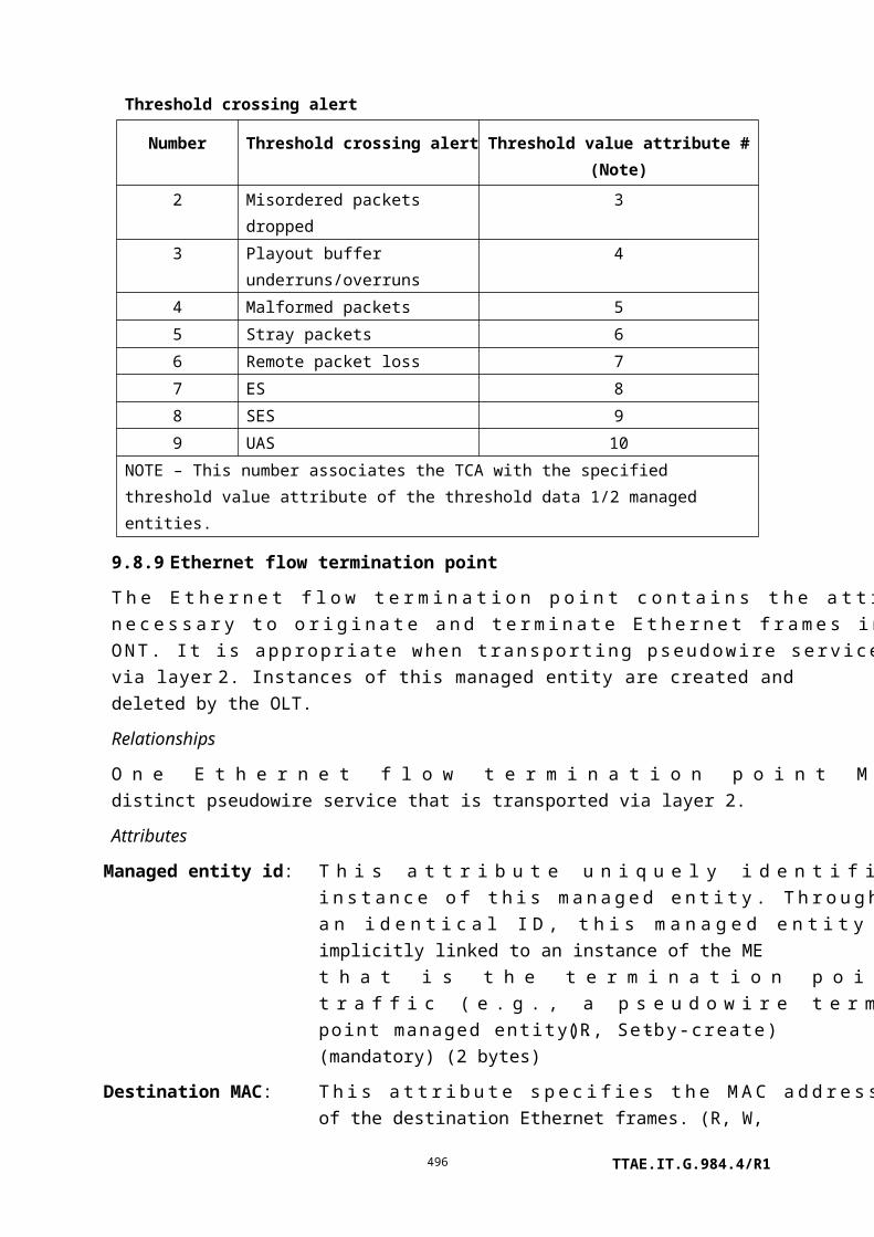
bursts: successfully corrected using FEC. (R) (optional) (4 bytes)
Rx missed bursts: This attribute counts bursts detected that were not received correctly (e.g., errors that were FEC uncorrectable). (R) (optional) (4 bytes)
Rx min power: This attribute is a low water mark that reports the lowest power level of all bursts received in the current interval, in units of dBmV. (R) (optional) (1 byte)
Rx max power: This attribute is a high water mark that reports the highest power level of all bursts received in the current interval, in units of dBmV. (R) (optional) (1 byte)
Rx current power: This attribute reports the power level of the latest burst received, in units of dBmV. (R) (optional) (1 byte)
Rx FEC corrected symbols:
This attribute counts the number of symbols that were corrected through the use of FEC. It provides an indicator of the bit error rate of the link. (R) (optional) (4 bytes)
Actions
Create, delete, set, get
Get current data (optional)
Notifications
Threshold crossing alert
Number Threshold crossing alert Threshold value attribute # (Note)
0 Rx total bursts 1
1 Rx good bursts 2
2 Rx FEC corrected bursts 3
3 Rx missed bursts 4
4 Rx min power 5
5 Rx max power 6
6 Rx current power 7
7 Rx FEC corrected symbols 8
NOTE – This number associates the TCA with the specified threshold value attribute of the
threshold data 1 managed entity.
9.13.9 VP network CTP-G
This managed entity represents the termination of VP links on an ONT. It aggregates connectivity functionality from the network view and alarms from the network element view
TTAE.IT.G.984.4/R1496

as well as artefacts from trails. Instances of this managed entity are created and deleted by the OLT.
An instance of the VP network CTP-G managed entity can be deleted only when no ATM interworking VCC termination point is associated with it. It is the responsibility of the OLT to ensure that this condition is met.
Relationships
Zero or more instances of the VP network CTP-G managed entity may exist for each instance of the interworking VCC termination point managed entity.
Attributes
Managed entity id: This attribute uniquely identifies each instance of this managed entity. It must be unique over all GEM port network CTP and VP network CTP-G MEs. (R, Set-by-create) (mandatory) (2 bytes)
VPI value: This attribute identifies the VPI value associated with the VP link being terminated. (R, W, Set-by-create) (mandatory) (2 bytes)
UNI pointer: This pointer indicates the xDSL physical path termination point UNI associated with this VP termination point. The bearer channel may be indicated by the two most significant bits of the pointer. (R, W, Set-by-create) (mandatory) (2 bytes)
Direction: This attribute specifies whether the VP link is used for UNI-to-ANI (value 1), ANI-to-UNI (value 02), or bidirectional (value 3) connection. (R, W, Set-by-create) (mandatory) (1 byte)
Priority queue pointer for downstream:
Not used, should be set to 0. (R, W, Set-by-create) (mandatory) (2 bytes)
Traffic management pointer for upstream:
Not used, should be set to 0. (R, W, Set-by-create) (mandatory) (2 bytes)
Traffic descriptor profile pointer:
Not used, should be set to 0. (R, W, Set-by-create) (optional) (2 bytes)
UNI counter: Not used, should be set to 0. (R) (optional) (1 byte)
Actions
Create, delete, get, set
Notifications
TTAE.IT.G.984.4/R1497

Alarm
Number Alarm Description
0 VP AIS LMIR VP-AIS receiving indication (optional)
1 VP RDI LMIR VP-RDI receiving indication (optional)
2 VP AIS LMIG VP-AIS generation indication (optional)
3 VP RDI LMIG VP-RDI generation indication (optional)
4 Segment loss of
continuity
Loss of continuity is detected when the VP network
CTP-G is a segment end point (optional)
5 End-to-end loss of
continuity
Loss of continuity can be detected when the VP network
CTP-G supports an interworking VCC termination point
(optional)
6..207 Reserved
208..223 Vendor-specific alarms Not to be standardized
9.13.10 VP performance monitoring history data
This managed entity collects performance monitoring data associated with a VP network CTP-G. Instances of this managed entity are created and deleted by the OLT.
Relationships
An instance of this managed entity is associated with an instance of the VP network CTP-G managed entity. The performance of upstream ATM flows is reported.
Attributes
Managed entity id: This attribute uniquely identifies each instance of this managed entity. Through an identical ID, this managed entity is implicitly linked to an instance of the VP network CTP-G. (R, Set-by-create) (mandatory) (2 bytes)
Interval end time: This attribute identifies the most recently finished 15-minute interval. (R) (mandatory) (1 byte)
Threshold data 1/2 id: This attribute points to an instance of the threshold data 1 managed entity that contains PM threshold values. Since no threshold value attribute number exceeds 7, a threshold data 2 ME is optional. (R, W, Set-by-create) (mandatory) (2 bytes)
Lost C = 0 + 1 cells: This attribute counts background cell loss. It cannot distinguish between cells lost because of header bit errors, ATM-level header errors, cell policing, or buffer overflows. It records only loss of information, independent of the priority of the cell. (R) (mandatory) (2 bytes)
TTAE.IT.G.984.4/R1498

Lost C = 0 cells: This attribute counts background cell loss. It cannot distinguish between cells lost because of header bit errors, ATM-level header errors, cell policing or buffer overflows. It records only loss of high priority cells. (R) (mandatory) (2 bytes)
Misinserted cells: This attribute counts cells that are misrouted to a monitored VP. (R) (mandatory) (2 bytes)
Transmitted C = 0 + 1 cells:
This attribute counts cells originated by the transmitting end point (i.e., backward reporting is assumed). (R) (mandatory) (5 bytes)
Transmitted C = 0 cells: This attribute counts high priority cells originated by the transmitting end point (i.e., backward reporting is assumed). (R) (mandatory) (5 bytes)
Impaired blocks: This severely errored cell block counter is incremented whenever one of the following events takes place: the number of misinserted cells reaches its threshold, the number of bipolar violations reaches its threshold, or the number of lost cells reaches its threshold. Threshold values are based on vendor-operator negotiation. (R) (mandatory) (2 bytes)
Actions
Create, delete, get, set
Get current data (optional)
Notifications
Threshold crossing alert
Number Threshold crossing alert Threshold value attribute # (Note)
0 Lost CLP = 0 + 1 cells 1
1 Lost CLP = 0 cells 2
2 Misinserted cells 3
3 Impaired blocks 4
NOTE – This number associates the TCA with the specified threshold value attribute of the
threshold data 1 managed entity.
9.13.11 Enhanced security control
This managed entity contains the capabilities, parameters and controls of enhanced G-PON security features. The attributes in this ME are intended to be used to implement a symmetric-
TTAE.IT.G.984.4/R1499

key-based three-step authentication process as described in the supplemental information section below.
Relationships
One instance of this managed entity is associated with the ONT managed entity.
Attributes
Managed entity id: This attribute uniquely identifies each instance of this managed entity. There is only one instance, number 0. (R) (mandatory) (2 bytes)
OLT crypto capabilities:
This attribute specifies the cryptographic mechanisms available at the OLT and is written by the OLT during authentication step 1. It is formatted as a bit map, where a 1 bit indicates that the particular algorithm is supported, and a 0 bit indicates it is not supported.
Bit positionalgorithm supported
1 (lsb=1, msb=128) AES-CMAC-128 (support is mandatory)2 HMAC-SHA-2563 HMAC-SHA-5124-128 Reserved
(W) (mandatory) (16 bytes)
TTAE.IT.G.984.4/R1500

OLT random challenge table:
This attribute specifies the random challenge issued by the OLT during authentication step 1. It is structured as a table, with each entry being 17 bytes. The first byte is the entry index, and the remaining 16 bytes are the content of the entry. In normal use, the OLT will write all the entries in the table, and then trigger the ONT's processing of the entire table using the OLT challenge status attribute. The table size is known by the maximum index set by the OLT. The OLT can clear the table with a set operation to index 0. (R, W) (mandatory) (17*N bytes)
OLT challenge status:
This Boolean attribute is used during authentication step 1. It controls and reports the status of the OLT crypto capabilities and the OLT random challenge table attributes. As a status report, the value false indicates that the values represented in those MEs are not complete. The value true indicates that they are complete. This attribute behaves as follows:
• If the OLT writes to either the OLT crypto capabilities or the OLT random challenge table, then the OLT challenge status attribute becomes false.
• If the OLT challenge status attribute is false and the OLT sets the OLT challenge status attribute to true, the ONT begins processing the contents of the OLT crypto capabilities and OLT random challenge table using the selected cryptographic hash algorithm.
The ONT initializes this attribute to the value false. (R, W) (mandatory) (1 byte)
ONT selected crypto capabilities:
This attribute specifies the cryptographic capability selected by the ONT in authentication step 2. Its value specifies one of the bit positions that has the value 1 in the OLT crypto capabilities attribute. (R) (mandatory) (1 byte)
ONT random challenge table:
This attribute specifies the random challenge issued by the ONT during authentication step 2. It is structured as a table, with each entry being 16 bytes of content. Once the OLT triggers a response to be generated using the OLT challenge status attribute, the ONT generates the response, and then writes the table (in a single operation). The AVC generated by this attribute signals the OLT that the challenge is ready, so that the OLT can commence a get/get-next sequence to obtain the table's contents. (R) (mandatory) (16*P
TTAE.IT.G.984.4/R1501

bytes)
ONT authentication result table:
(authentication step 2) This attribute contains the result of the authentication computation from the ONT, according to the ONT selected crypto capabilities attribute. The value of the ONT authentication result table is equal to:
SelectedHashFunction (PSK | ONT_selected_crypto capabilities | OLT_random_challenge_table | ONT_random_challenge_table| 0x0000 0000 0000 0000),
where "|" denotes concatenation.
This attribute is structured as a table, with each entry being 16 bytes of content. Once the OLT triggers a response to be generated using the OLT challenge status attribute, the ONT generates the response, and then writes the table (in a single operation). The AVC generated by this attribute signals the OLT that the response is ready, so that the OLT can commence a get/get-next sequence to obtain the table's contents. (R) (mandatory) (16*Q bytes)
OLT authentication result table:
This attribute is used in authentication step 3. It specifies the result of the authentication computation from the OLT. The OLT response is equal to:
SelectedHashFunction (PSK | ONU_selected_crypto capabilities | ONT_random_challenge_table | OLT_random_challenge_table | ONT_serial_number).
The ONT_serial_number is the serial number attribute of the ONT-G managed entity.
This attribute is structured as a table, with each entry being 17 bytes. The first byte is the entry index; the remaining 16 bytes are content. The OLT writes all entries in the table, and then triggers the ONT's processing of the table using the OLT result status attribute. The table size is known by the maximum index set by the OLT. The OLT can clear the table with a set operation to index 0. (W) (mandatory) (17*R bytes)
OLT result status: (authentication step 3) This Boolean attribute controls and reports the status of the OLT authentication result table attribute. As a status report, the value false indicates that the value represented in the OLT authentication result table is not complete. The value true indicates that it is complete. This attribute behaves as follows:
TTAE.IT.G.984.4/R1502

• If the OLT writes to the OLT authentication result table, then OLT result status becomes false.
• If the OLT result status is false and the OLT sets the OLT result status to true, the ONT begins processing the contents of the OLT authentication result table using the specified algorithm.
(R, W) (mandatory) (1 byte)
ONT authentication status:
This attribute indicates the status of the authentication relationship from the perspective of the ONT. It has the following values:
0 Inactive: the authentication procedure is not currently active.
1 OLT challenge pending: the authentication procedure is under way, and is between message step 1 and 2.
2 ONT challenge pending: the authentication procedure is under way, and is between message step 2 and 3.
3 Authentication success: the procedure has completed, and the ONT has authenticated the OLT.
4 Authentication failure: the procedure has completed, and the ONT has not authenticated the OLT.
5 Error: the authentication procedure was started but could not be completed.
When the ONT authentication status has the value 3, encryption keys exchanged in the TC layer will be encrypted using the session key. The OLT should check the value of this attribute before initiating a key switch.
(R) (mandatory) (1 byte)
Session key name: Following successful authentication, this register contains the "name" of the current session key. The session key is defined as:
SelectedHashFunction (PSK | OLT random_challenge | ONT random_challenge)
The session key name is defined as:
SelectedHashFunction (PSK | ONT random_challenge | OLT random_challenge | 0x 3141 5926 5358 9793 3141 5926 5358 9793)
If the selected hash function generates more than 128 bits, the result
TTAE.IT.G.984.4/R1503

is truncated to the leftmost (most significant) 128 bits.
Upon termination of a session key (e.g., due to an ONT reset or due to an ONT-local decision that the session key has expired), the ONT sets the session key name to all zeros. (R) (mandatory) (16 bytes)
Actions
Get, set, get next
Notifications
Attribute value change
Number Attribute value change Description
1..4 Reserved
5 ONT random challenge table A new ONT challenge has been loaded into the
table for the OLT to retrieve
6 ONT authentication result table A new ONT response has been loaded into the
table for the OLT to retrieve
7..9 Reserved
10 ONT authentication status The ONT authentication status has changed
11..16 Reserved
Supplementary information
This managed entity contains the facilities to perform a conventional three-step hash-based authentication sequence found in [b-ISO/IEC 9798-4] (used in DSL systems that employ MS-CHAPv2 and elsewhere) using get and set messages.
The logical structure of the conventional three-step sequence is as follows:
Message 1: (Peer 1 peer 2) my_cryptographic_capabilities, random_challenge_1
Message 2: (Peer 2 peer 1): selected_cryptographic_capabilities, random_challenge_2, MsgHash (PSK, selected_cryptographic_capabilities, random_challenge_1, random_challenge_2, peer_1_identity)
Message 3: (Peer 1 peer 2): MsgHash (PSK, selected_cryptographic_capabilities, random_challenge_2, random_challenge_1, peer_2_identity)
Where:
MsgHash () is a keyed hash function of the message
PSK is the pre-shared key known only to the peers of the session
Peer_1_identity is always "0x0000 0000 0000 0000"
TTAE.IT.G.984.4/R1504

Peer_2_identity is the ONT serial number
The prerequisite is the availability of a pre-shared secret: PSK. A PSK of 128 bits simplifies the application of security algorithms based on AES-128 (e.g., AES-CMAC-128). A PSK is associated with a particular ONT and is stored at that ONT and at the operator infrastructure. On the operator side, the PSK for a particular ONT might be stored in the physically-connected OLT, or at a central server that the OLT accesses during authentication. Configuration of the PSK into the ONT and into the operator infrastructure may be done in any manner that satisfies these requirements.
In OMCI, the authentication message sequence follows the steps illustrated in Figure 9.13.11-1.
OLT ONT
Set* [OLT crypto capabilities, OLT random challenge table]
Get_response [ ]
Get [ONT selected crypto capabilities, ONT random challenge table, ONT authentication result table]
Set* [OLT authentication result table]
Set [OLT challenge status = true]
Notation: Set* indicates multiple set operations as needed to fill table
Set [OLT result status = true]
AVC [ONT random challenge table complete]
AVC [ONT authentication result table complete]
AVC [ONT authentication status]
Get_response [ ]
Get [Session key name]
Figure 9.13.11-1 – Authentication message exchange sequence
TTAE.IT.G.984.4/R1505

ONT states
As tracked by the ONT authentication status attribute and illustrated in Figure 9.13.11-2, the mutual authentication functionality in the ONT exists in the state machine described below. It is to be understood that this state machine runs entirely in O5, the operation state defined in [ITU-T G.984.3].
a) Inactive – S0
After ONT registration, the ONT is in inactive state. The OLT initiates the authentication process by writing a challenge into the OLT random challenge table.
b) OLT challenge pending – S1
After the OLT writes its challenge to the OLT random challenge register, the ONT enters this state.
The ONT transitions to ONT challenge pending state after it has chosen the ONT random challenge and calculated the ONT authentication result table.
If the ONT was unable to perform the operations necessary to transition to ONT challenge pending, it enters the authentication error state S5.
While the ONT is in OLT challenge pending state, the OLT should not write new values into the OLT random challenge table.
c) ONT challenge pending – S2
In this state, the ONT waits for the OLT to read the relevant registers and write the result of the ONT's authentication challenge to the OLT authentication result table.
If no response to the ONT's challenge is received in the OLT authentication hash register within three seconds, the ONT transitions to the authentication error state S5. If a response is received, the ONT validates it and transitions either to authenticated state S3 or to deauthenticated state S4.
While the ONT is in the ONT challenge pending state, the OLT should not write new values into the OLT random challenge table.
d) Authentication success – S3
The ONT must set a valid value for the session key name attribute before it enters the authentication success state. The OLT will typically read the session_key name attribute when it receives the AVC indicating that the ONT authentication status attribute has changed to state S3 to ensure that the ONT is synchronized, and the new key is ready to be utilized within the TC layer PLOAM function.
e) Authentication failure – S4
The ONT enters this state from the ONT challenge pending state whenever the authentication procedure fails, due to, e.g., a PSK mismatch (OLT authentication result table differs from the MsgHash value computed by the ONT).
TTAE.IT.G.984.4/R1506

f) Authentication error – S5
This state indicates that the authentication procedure was started but could not be completed.
NOTE 1 – Timer T1 – ONT challenge pending timer. Timer T1 is used to abort an unsuccessful OLT
authentication attempt by limiting the overall time an ONT can remain in state S2. The recommended
value of T1 is 3 seconds.
NOTE 2 – Timer T2 – Authentication failure timer. Timer T2 is used to assert a mismatch of the
session key condition by limiting the time an ONT can remain in state S4. The recommended value of
T2 is 1 second.
TTAE.IT.G.984.4/R1507

NOTE 3 – Timer T3 – Authentication error timer. Timer T3 is used to assert a failure of authentication
condition by limiting the time an ONT can remain in state S5. The recommended value of T3 is 1
second.
Figure 9.13.11-2 – ONT state diagram
Synchronization with TC layer and security considerations
When the ONT is in authenticated state, it uses its session key to encrypt the encryption key transmitted in the encryption_key PLOAM message.
The session key is defined as:
SessionKey = SelectedHashFunction (PSK | OLT random_challenge | ONT random_challenge)
where SelectedHashFunction () is the hash function selected by the ONT in the ONT selected crypto capabilities attribute from the list supplied by the OLT.
The encryption of the encryption key shall be performed using AES-128 in electronic codebook (ECB) mode.
Since the integrity of the encryption key carried in the encryption key PLOAM message is not protected, there is the possibility that the key can be forged or replayed by an attacker. A forged key is a form of denial-of-service attack, and both forged and replayed keys can be detected with key synchronization mechanisms. A replay attack, however, could force the OLT to use an old encryption key, which violates the security requirements of the downstream data encryption. Consequently, an OLT designed to resist a replay attack should ensure that the ONT does not send a previously used encryption key between authentication cycles.
9.14 Mid-span PON reach extender
Figure 9.14-1 – Mid-span PON reach extender
TTAE.IT.G.984.4/R1508

[ITU-T G.984.6] defines a mid-span PON reach extender (RE). A reach extender may extend more than one PON, using optical amplification or optical-electrical-optical regeneration technology. For easy reference, Figure 9.14-1 illustrates the interface designations.
The RE model includes one built-in ONT, which serves for management of the RE itself, as well as for optional subscriber or craft UNIs. The ONT is therefore able to use any of the managed entities defined elsewhere in this Recommendation, including the ANI-G and T-CONT MEs, which represent the built-in ONT's individual uplink.
NOTE – Although the built-in management ONT is physically contained within a physical reach
extender equipment, the management model perspective is that the ONT software controls the entire
equipment. In terms of the model, therefore, the management ONT contains the reach extender
equipment and functionality.
This clause defines additional managed entities that pertain to the reach extender function separately.
The current scope of the RE model includes the use of either regeneration (OEO) or optical amplification (OA) in the upstream and in the downstream directions, independently. Split ratio enhancement (more than one UNI for every ANI) is also included. This results in eight possible arrangements, as follows.
NOTE – Each amplifier ME is associated with an RE common amplifier parameters ME.
Downstream
technology
Upstream technology
Internal optical
splitModel
OEO OEO 1:1 1 PPTP RE UNI pointing to 1 RE ANI-G, all attributes
active.
OEO OEO 1:N N PPTP RE UNIs pointing to 1 RE ANI-G, all attributes
active.
OA OA 1:1 1 RE upstream amplifier pointing to 1 RE downstream
amplifier.
OA OA 1:N N RE upstream amplifiers pointing to 1 RE downstream
amplifier.
OA OEO 1:1 1 PPTP RE UNI pointing to 1 RE ANI-G. Downstream
optical attributes of the RE ANI-G not used. 1 downstream
amplifier, likely sharing ME ID with the RE ANI-G.
TTAE.IT.G.984.4/R1509

Downstream
technology
Upstream technology
Internal optical
splitModel
OA OEO 1:N N PPTP RE UNIs pointing to 1 RE ANI-G. Downstream
optical attributes of the RE ANI-G not used. 1 downstream
amplifier, likely sharing ME ID with RE ANI-G.
OEO OA 1:1 1 PPTP RE UNI pointing to 1 RE ANI-G. Upstream
optical attributes of the RE UNI not used. 1 upstream
amplifier, likely sharing ME ID with the PPTP RE UNI.
OEO OA 1:N N PPTP RE UNIs pointing to 1 RE ANI-G. Upstream
optical attributes of the RE UNI not used. N upstream
amplifiers, likely sharing ME IDs with the PPTP RE UNIs.
9.14.1 RE ANI-G
This managed entity organizes data associated with each R'/S' physical interface supported by the ONT. The ONT automatically creates one instance of this managed entity for each R'/S' physical port (transmit and/or receive).
Relationships
An instance of this managed entity is associated with each R'/S' physical interface, and is associated with one or more instances of PPTP RE UNI.
Attributes
Managed entity id: This attribute uniquely identifies each instance of this managed entity. Its value indicates the physical position of the R'/S' interface. The first byte is the slot id (defined in clause 9.1.5). The second byte is the port id.
NOTE – This ME ID may be identical to that of an RE downstream
amplifier if it shares the same physical slot and port.
(R) (mandatory) (2 bytes)
Administrative state: This attribute locks (1) and unlocks (0) the functions performed by this managed entity. When the administrative state is set to lock, all functions of this managed entity are blocked, and alarms, TCAs and AVCs for this managed entity and all dependent managed entities are no longer generated. Selection of a default value for this attribute is outside the scope of this Recommendation. (R, W) (mandatory) (1 byte)
Operational state: This attribute indicates whether or not the managed entity is
TTAE.IT.G.984.4/R1510

capable of performing its function. Valid values are enabled (0) and disabled (1). (R) (optional) (1 byte)
ARC: See clause I.1.8. (R, W) (optional) (1 byte)
ARC interval: See clause I.1.8. (R, W) (optional) (1 byte)
Optical signal level: This attribute reports the current measurement of total optical signal level at 1490 nm. Its value is a 2s complement integer referred to 1 mW (i.e., dBm), with 0.002 dB granularity. (R) (optional) (2 bytes)
Lower optical threshold:
This attribute specifies the optical level that the ONT uses to declare the 1490 nm low received optical power alarm. Valid values are –127 dBm (coded as 254) to 0 dBm (coded as 0) in 0.5 dB increments. The default value 0xFF selects the ONT's internal policy. (R, W) (optional) (1 byte)
Upper optical threshold:
This attribute specifies the optical level that the ONT uses to declare the 1490 nm high received optical power alarm. Valid values are –127 dBm (coded as 254) to 0 dBm (coded as 0) in 0.5 dB increments. The default value 0xFF selects the ONT's internal policy. (R, W) (optional) (1 byte)
Transmit optical level: This attribute reports the current measurement of the optical transmit power level. Its value is a 2s complement integer referred to 1 mW (i.e., dBm), with 0.002 dB granularity. (R) (optional) (2 bytes)
Lower transmit power threshold:
This attribute specifies the transmit power level that the ONT uses to declare the low transmit optical power alarm. Its value is a 2s complement integer referred to 1 mW (i.e., dBm), with 0.5 dB granularity. The default value 0x7F selects the ONT's internal policy. (R, W) (optional) (1 byte)
Upper transmit power threshold:
This attribute specifies the transmit power level that the ONT uses to declare the high transmit optical power alarm. Its value is a 2s complement integer referred to 1 mW (i.e., dBm), with 0.5 dB granularity. The default value 0x7F selects the ONT's internal policy. (R, W) (optional) (1 byte)
Usage mode: In a mid-span PON reach extender, an R'/S' interface may be used as the PON interface for the embedded ONT and/or the uplink interface for an S'/R' interface. This attribute specifies the usage of the R'/S' interface. (R, W) (mandatory) (1 byte)
TTAE.IT.G.984.4/R1511

0: Disable1: This R'/S' interface is used as the uplink for the embedded
ONT2: This R'/S' interface is used as the uplink for one or more
PPTP RE UNI(s)3: This R'/S' interface is used as the uplink for both the
embedded ONT and one or more PPTP RE UNI(s) (in a time division fashion).
Actions
Get, set
Test: Test the RE-ANI. The test action can be used to perform optical line supervision tests; refer to Appendix II.
Notifications
Attribute value change
Number Attribute value change Description
1 N/A
2 Op state Operational state of RE ANI-G
3 ARC Alarm reporting control cancellation
4..11 N/A
12..16 Reserved
Alarm
Number Alarm Description
0 Low received optical
power
Received 1490 nm optical power below threshold
1 High received optical
power
Received 1490 nm optical power above threshold
2 Low transmit optical
power
Transmitted 1310 nm optical power below lower threshold
3 High transmit optical
power
Transmitted 1310 nm optical power above upper threshold
4 High laser bias current Laser bias current above threshold determined by vendor;
laser end of life pending
TTAE.IT.G.984.4/R1512

5..207 Reserved
208..223 Vendor-specific alarms Not to be standardized
Test result: The ONT may report a test result autonomously if it performs self-test functions autonomously.
9.14.2 Physical path termination point RE UNI
This managed entity represents an S'/R' interface in a mid-span PON reach extender, where physical paths terminate and physical path level functions are performed (transmit and/or receive).
The ONT automatically creates an instance of this managed entity for each S'/R' interface port:
• When the ONT has mid-span PON reach extender S'/R' interface ports built into its factory configuration.
• When a cardholder is provisioned to expect a circuit pack of mid-span PON reach extender S'/R' UNI type.
• When a cardholder provisioned for plug and play is equipped with a circuit pack of mid-span PON reach extender UNI type. Note that the installation of a plug and play card may indicate the presence of mid-span PON reach extender UNI port via equipment ID as well as its type, and indeed may cause the ONT to instantiate a port mapping package that specifies mid-span PON reach extender UNI and ANI ports.
The ONT automatically deletes instances of this managed entity when a cardholder is neither provisioned to expect a mid-span PON reach extender UNI circuit pack, nor is it equipped with a mid-span PON reach extender UNI circuit pack.
Relationships
An instance of this managed entity is associated with each instance of a mid-span PON reach extender S'/R' physical interface.
Attributes
Managed entity id: This attribute uniquely identifies each instance of this managed entity. This 2-byte number indicates the physical position of the UNI. The first byte is the slot ID (defined in clause 9.1.5). The second byte is the port ID, with range 1..255.
NOTE – This ME ID may be identical to that of an RE upstream
amplifier if it shares the same physical slot and port.
(R) (mandatory) (2 bytes)
TTAE.IT.G.984.4/R1513

Administrative state: This attribute locks (1) and unlocks (0) the functions performed by this managed entity. When the administrative state is set to lock, all user functions of this UNI are blocked, and alarms, TCAs and AVCs for this managed entity and all dependent managed entities are no longer generated. Selection of a default value for this attribute is outside the scope of this Recommendation. (R, W) (mandatory) (1 byte)
Operational state: This attribute indicates whether or not the managed entity is capable of performing its function. Valid values are enabled (0) and disabled (1). (R) (optional) (1 byte)
ARC: See clause I.1.8. (R, W) (optional) (1 byte)
ARC interval: See clause I.1.8. (R, W) (optional) (1 byte)
RE ANI-G pointer: This attribute points to an RE ANI-G instance. (R, W) (mandatory) (2 bytes)
Total optical receive signal level table:
This table attribute reports a series of measurements of time averaged received upstream optical signal level at 1310 nm. The measurement circuit should have a temporal response similar to a simple 1 pole low pass filter, with an effective time constant on the order of a GTC frame time. Each table entry has a two-byte frame counter field (most significant end), and a two-byte power measurement field. The frame counter field contains the least significant 16 bits of the superframe counter received closest to the time of the measurement. The power measurement field is a 2s complement integer referred to 1 mW (i.e., dBm), with 0.002 dB granularity. The ONT equipment should add entries to this table as frequently as is reasonable. The ONT should clear the table once it is read by the OLT. (R) (optional) (4N bytes, where N is the number of measurements present.)
Per burst receive signal level table:
This table attribute reports the most recent measurement of received burst upstream optical signal level at 1310 nm. Each table entry has a two-byte ONU-ID field (Note) (most significant end), and a two-byte power measurement field. The power measurement field is a 2s complement integer referred to 1 mW (i.e., dBm), with 0.002 dB granularity. (R) (optional) (4N bytes, where N is the number of distinct ONTs connected to the S'/R' interface.)
NOTE – In its initial definition, only one byte was assigned to
TTAE.IT.G.984.4/R1514

ONU-ID. This was changed to two bytes in anticipation that future PON technologies may support a split ratio greater than 256.
Lower receive optical threshold:
This attribute specifies the optical level that the ONT uses to declare the burst mode 1310 nm low received optical power alarm. Valid values are –127 dBm (coded as 254) to 0 dBm (coded as 0) in 0.5 dB increments. The default value 0xFF selects the ONT's internal policy. (R, W) (optional) (1 byte)
Upper receive optical threshold:
This attribute specifies the optical level that the ONT uses to declare the burst mode 1310 nm high received optical power alarm. Valid values are –127 dBm (coded as 254) to 0 dBm (coded as 0) in 0.5 dB increments. The default value 0xFF selects the ONT's internal policy. (R, W) (optional) (1 byte)
Transmit optical level: This attribute reports the current measurement of optical transmit power level at 1490 nm. Its value is a 2s complement integer referred to 1 mW (i.e., dBm), with 0.002 dB granularity. (R) (optional) (2 bytes)
Lower transmit power threshold:
This attribute specifies the transmit power level at 1490 nm in the S'/R' interface that the ONT uses to declare the low transmit optical power alarm. Its value is a 2s complement integer referred to 1 mW (i.e., dBm), with 0.5 dB granularity. The default value 0x7F selects the ONT's internal policy. (R, W) (optional) (1 byte)
Upper transmit power threshold:
This attribute specifies the transmit power level at 1490 nm in the S'/R' interface that the ONT uses to declare the high transmit optical power alarm. Its value is a 2s complement integer referred to 1 mW (i.e., dBm), with 0.5 dB granularity. The default value 0x7F selects the ONT's internal policy. (R, W) (optional) (1 byte)
Additional preamble: This attribute indicates the number of bytes of PLOu preamble that are unavoidably consumed while passing the reach extender. (R) (mandatory) (1 byte)
Additional guard time:
This attribute indicates the number of bytes of extra guard time that are needed to ensure correct operation with the reach extender. (R) (mandatory) (1 byte)
Actions
Get, get next, set
TTAE.IT.G.984.4/R1515

Test: Test the PPTP RE UNI. The test action can be used to perform optical line supervision tests; refer to Appendix II.
Notifications
Attribute value change
Number Attribute value change Description
1 N/A
2 Op state Operational state of PPTP RE UNI
3 ARC ARC timer expiration
4..14 N/A
15..16 Reserved
Alarm
Number Alarm Description
0 Low received optical
power
Received 1310 nm optical power of one or more ONTs
below threshold
1 High received optical
power
Received 1310 nm optical power of one or more ONTs
above threshold
2 Low transmit optical
power
Transmit 1490 nm optical power below lower threshold
3 High transmit optical
power
Transmit 1490 nm optical power above upper threshold
4 High laser bias current Laser bias current above threshold determined by vendor;
laser end of life pending
5 S'/R' LOSS S'/R' LOSS detected, No optical signal received at the S'/R'
upstream interface in 500 µs
6..207 Reserved
208..223 Vendor-specific alarms Not to be standardized
9.14.3 RE upstream amplifier
This managed entity organizes data associated with each upstream reach extender optical amplifier supported by the ONT. The ONT automatically creates one instance of this managed entity for each upstream optical amplifier.
TTAE.IT.G.984.4/R1516

Relationships
An instance of this managed entity is associated with an upstream optical amplifier, and is associated with one instance of the circuit pack.
Attributes
Managed entity id: This attribute uniquely identifies each instance of this managed entity. Its value indicates the physical position of the upstream optical amplifier. The first byte is the slot id (defined in clause 9.1.5). The second byte is the port id.
NOTE – This ME ID may be identical to that of a PPTP RE UNI if it
shares the same physical slot and port. (R) (mandatory) (2 bytes)
Administrative state: This attribute locks (1) and unlocks (0) the functions performed by this managed entity. When the administrative state is set to lock, all functions of this managed entity are blocked, and alarms, TCAs and AVCs for this managed entity and all dependent managed entities are no longer generated. Selection of a default value for this attribute is outside the scope of this Recommendation. (R, W) (mandatory) (1 byte)
Operational state: This attribute indicates whether or not the managed entity is capable of performing its function. Valid values are enabled (0) and disabled (1). (R) (optional) (1 byte)
Operational mode: This attribute indicates the operational mode.
0 Constant gain1 Constant output power2 Autonomous
(R,W) (mandatory) (1 byte)
ARC: See clause I.1.8. (R, W) (optional) (1 byte)
ARC interval: See clause I.1.8. (R, W) (optional) (1 byte)
RE downstream amplifier pointer:
This attribute points to an RE downstream amplifier instance. The default value is 0xFFFF. (R, W) (mandatory) (2 bytes)
TTAE.IT.G.984.4/R1517

Total optical receive signal level table:
This table attribute reports a series of measurements of time averaged input upstream optical signal level at 1310 nm. The measurement circuit should have a temporal response similar to a simple 1 pole low pass filter, with an effective time constant on the order of a GTC frame time. Each table entry has a two-byte frame counter field (most significant end), and a two-byte power measurement field. The frame counter field contains the least significant 16 bits of the superframe counter received closest to the time of the measurement. The power measurement field is a 2s complement integer referred to 1 mW (i.e., dBm), with 0.002 dB granularity. The ONT equipment should add entries to this table as frequently as is reasonable. The ONT should clear the table once it is read by the OLT. (R) (optional) (4N bytes, where N is the number of measurements present.)
Per burst receive signal level table:
This table attribute reports the most recent measurement of received burst upstream optical signal level at 1310 nm. Each table entry has a two-byte ONU-ID field (Note) (most significant end), and a two-byte power measurement field. The power measurement field is a 2s complement integer referred to 1 mW (i.e., dBm), with 0.002 dB granularity. (R) (optional) (4N bytes, where N is the number of distinct ONTs connected to the S'/R' interface.)
NOTE – In its initial definition, only one byte was assigned to ONU-ID. This was changed to two bytes in anticipation that future PON technologies may support a split ratio greater than 256.
Lower receive optical threshold:
This attribute specifies the optical level that the ONT uses to declare the low input optical power alarm. Valid values are –127 dBm (coded as 254) to 0 dBm (coded as 0) in 0.5 dB increments. The default value 0xFF selects the ONT's internal policy. (R, W) (optional) (1 byte)
Upper receive optical threshold:
This attribute specifies the optical level that the ONT uses to declare the high input optical power alarm. Valid values are –127 dBm (coded as 254) to 0 dBm (coded as 0) in 0.5 dB increments. The default value 0xFF selects the ONT's internal policy. (R, W) (optional) (1 byte)
Transmit optical signal level:
This attribute reports the current measurement of the output optical signal level of the upstream optical amplifier. Its value is a
TTAE.IT.G.984.4/R1518
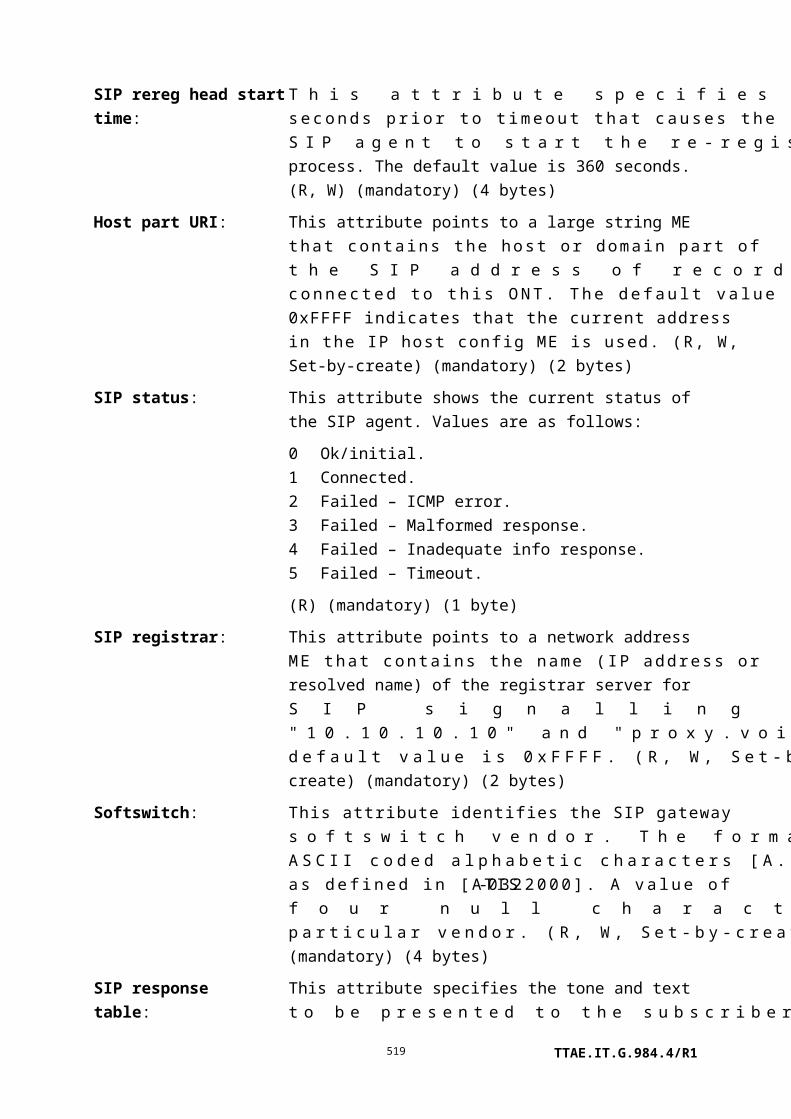
2s complement integer referred to 1 mW (i.e., dBm), with 0.002 dB granularity. (R) (optional) (2 bytes)
Lower transmit optical threshold:
This attribute specifies the optical level that the ONT uses to declare the low output optical power alarm. Its value is a 2s complement integer referred to 1 mW (i.e., dBm), with 0.5 dB granularity. The default value 0x7F selects the ONT's internal policy. (R, W) (optional) (1 byte)
Upper transmit optical threshold:
This attribute specifies the optical level that the ONT uses to declare the high output optical power alarm. Its value is a 2s complement integer referred to 1 mW (i.e., dBm), with 0.5 dB granularity. The default value 0x7F selects the ONT's internal policy. (R, W) (optional) (1 byte)
Actions
Get, get next, set
Test: Test the upstream amplifier. The test action can be used to perform optical line supervision tests; refer to Appendix II.
Notifications
Attribute value change
Number Attribute value change Description
1 N/A
2 Op state Operational state of RE upstream amplifier
3 N/A
4 ARC Alarm reporting control cancellation
5..13 N/A
14..16 Reserved
Alarm
Number Alarm Description
0 Low received optical power Received 1310 nm optical power of one or more
ONTs below threshold
1 High received optical power Received 1310 nm optical power of one or more
ONTs above threshold
TTAE.IT.G.984.4/R1519

2 Low transmit optical power Transmit 1310 nm optical power below lower
threshold
3 High transmit optical power Transmit 1310 nm optical power above upper
threshold
4 High laser bias current Laser bias current above threshold determined by
vendor; laser end of life pending
5 S'/R' LOSS S'/R' LOSS detected, No optical signal received at the
S'/R' upstream interface in 500 µs
6..207 Reserved
208..223 Vendor-specific alarms Not to be standardized
Test result: The ONT may report a test result autonomously if it performs self-test functions autonomously.
9.14.4 RE downstream amplifier
This managed entity organizes data associated with each optical amplifier for downstream data supported by the ONT. The ONT automatically creates one instance of this managed entity for each downstream optical amplifier.
Relationships
An instance of this managed entity is associated with a downstream optical amplifier and with one instance of the circuit pack ME.
Attributes
Managed entity id: This attribute uniquely identifies each instance of this managed entity. Its value indicates the physical position of the downstream optical amplifier. The first byte is the slot id (defined in clause 9.1.5). The second byte is the port id.
NOTE – This ME ID may be identical to that of an RE ANI-G if it
shares the same physical slot-port.
(R) (mandatory) (2 bytes)
TTAE.IT.G.984.4/R1520

Administrative state: This attribute locks (1) and unlocks (0) the functions performed by this managed entity. When the administrative state is set to lock, all functions of this managed entity are blocked, and alarms, TCAs and AVCs for this managed entity and all dependent managed entities are no longer generated. Selection of a default value for this attribute is outside the scope of this Recommendation. (R, W) (mandatory) (1 byte)
Operational state: This attribute indicates whether or not the managed entity is capable of performing its function. Valid values are enabled (0) and disabled (1). (R) (optional) (1 byte)
ARC: See clause I.1.8. (R, W) (optional) (1 byte)
ARC interval: See clause I.1.8. (R, W) (optional) (1 byte)
Operational mode: This attribute indicates the operational mode.
0 Constant gain1 Constant output power2 Autonomous
(R,W) (mandatory) (1 byte)
Input optical signal level:
This attribute reports the current measurement of the 1490 nm input optical signal level of the downstream optical amplifier. Its value is a 2s complement integer referred to 1 mW (i.e., dBm), with 0.002 dB granularity. (R) (optional) (2 bytes)
Lower input optical threshold:
This attribute specifies the optical level the ONT uses to declare the low input optical power alarm. Valid values are –127 dBm (coded as 254) to 0 dBm (coded as 0) in 0.5 dB increments. The default value 0xFF selects the ONT's internal policy. (R, W) (optional) (1 byte)
Upper input optical threshold:
This attribute specifies the optical level the ONT uses to declare the high input optical power alarm. Valid values are –127 dBm (coded as 254) to 0 dBm (coded as 0) in 0.5 dB increments. The default value 0xFF selects the ONT's internal policy. (R, W) (optional) (1 byte)
Output optical signal level:
This attribute reports the current measurement of the output optical signal level of the downstream optical amplifier. Its value is a 2s complement integer referred to 1 mW (i.e., dBm), with 0.002 dB granularity. (R) (optional) (2 bytes)
Lower output optical This attribute specifies the optical level the ONT uses to declare
TTAE.IT.G.984.4/R1521

threshold: the low output optical power alarm. Its value is a 2s complement integer referred to 1 mW (i.e., dBm), with 0.5 dB granularity. The default value 0x7F selects the ONT's internal policy. (R, W) (optional) (1 byte)
Upper output optical threshold:
This attribute specifies the optical level the ONT uses to declare the high output optical power alarm. Its value is a 2s complement integer referred to 1 mW (i.e., dBm), with 0.5 dB granularity. The default value 0x7F selects the ONT's internal policy. (R, W) (optional) (1 byte)
R'S' splitter coupling ratio:
This attribute reports the coupling ratio of the splitter at the R'S' interface that connects the embedded ONT and the amplifiers to the optical trunk line. Valid values are 99:1 (coded as 99 decimal) to 1:99 (coded as 1 decimal), where the first value is the value encoded and is the percentage of the optical signal connected to the amplifier. The default value 0xFF indicates that there is no splitter connected to this upstream/downstream amplifier pair. (R) (optional) (1 byte)
Actions
Get, set
Test: Test the RE downstream amplifier. The test action can be used to perform optical line supervision tests; refer to Appendix II.
Notifications
Attribute value change
Number Attribute value change Description
1 N/A
2 Op state Operational state of RE downstream amplifier
3 ARC Alarm reporting control cancellation
4..12 N/A
13..16 Reserved
Alarm
Number Alarm Description
0 Low received optical power Received 1490 nm optical power below threshold
TTAE.IT.G.984.4/R1522

1 High received optical power Received 1490 nm optical power above threshold
2 Low transmit optical power Transmit 1490 nm optical power below lower
threshold
3 High transmit optical power Transmit 1490 nm optical power above upper
threshold
4 High laser bias current Laser bias current above threshold determined by
vendor; laser end of life pending
5..207 Reserved
208..223 Vendor-specific alarms Not to be standardized
Test result: The ONT may report a test result autonomously if it performs self-test functions autonomously.
9.14.5 RE config portal
The RE config portal managed entity provides a way for the OLT to discover the configuration delivered to an ONT by a non-OMCI reach extender configuration method (SNMP, etc.). Text retrieved from this ME is not required to be understood by the OLT or EMS, but it may be useful for human or vendor-specific analysis tools.
An instance of this managed entity may be created by an ONT that supports non-OMCI RE configuration. It is not reported during a MIB upload.
Relationships
One instance of this managed entity is associated with an instance of a TCP/UDP config data managed entity.
TTAE.IT.G.984.4/R1523
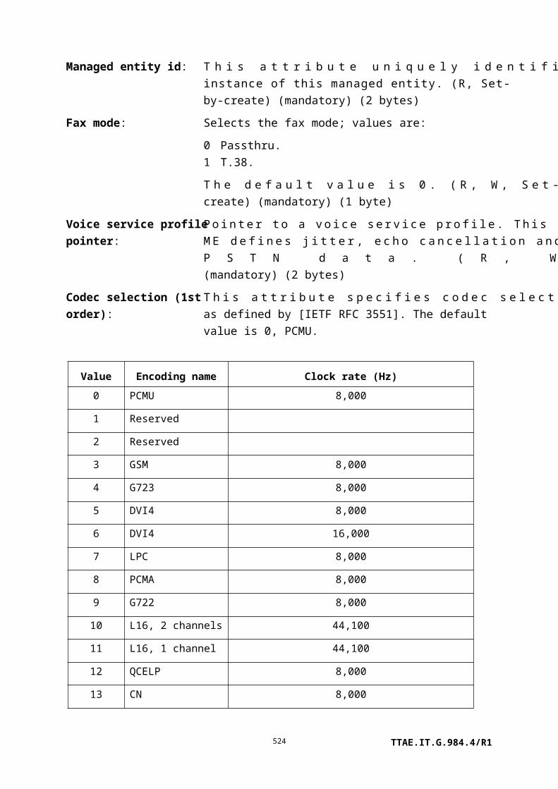
Attributes
Managed entity ID: This attribute uniquely identifies each instance of this managed entity. There is one instance, number 0. (R) (mandatory) (2 bytes)
Configuration text table:
This attribute is used to pass a textual representation of the RE configuration back to the OLT. The contents are vendor specific. The get, get next sequence must be used with this attribute since its size is unspecified. Upon ME instantiation, the ONT sets this attribute to 0. (R) (mandatory) (x bytes)
TCP/UDP pointer: This pointer associates the RE config portal with the TCP/UDP config data ME to be used for communication with any valid and necessary in-band protocol server. The default value is 0xFFFF. (R, W) (mandatory) (2 bytes)
Actions
Get, get next
Notifications
Attribute value change
Number Attribute value change Description
1 Configuration text Indicates an update to the RE configuration from a
non-OMCI interface. Because the attribute is a table,
the AVC contains no information about its value. The
OLT must use the get, get next action sequence if it
wishes to obtain the updated attribute content.
2..16 Reserved
9.14.6 RE common amplifier parameters
This managed entity organizes data associated with each optical amplifier supported by the ONT. The ONT automatically creates one instance of this managed entity for each upstream or downstream optical amplifier.
Relationships
An instance of this managed entity is associated with an optical amplifier and with one instance of the RE downstream amplifier or RE upstream amplifier ME.
Attributes
Managed entity id: This attribute uniquely identifies each instance of this managed entity. Its value indicates the physical position of the upstream or downstream optical amplifier. The first byte is the slot id (defined
TTAE.IT.G.984.4/R1524

in clause 9.1.5). The second byte is the port id. (R) (mandatory) (2 bytes)
Gain: This attribute reports the current measurement of gain, in dB, of the optical amplifier. Its value is a 2s complement integer with 0.25 dB granularity, having a range from –32 dB to 31.5 dB. The value 0x7F indicates that the current measured gain is 0, i.e., negative infinity in dB terms. (R) (optional) (1 byte)
Lower gain threshold: This attribute specifies the gain the ONT uses to declare the low gain alarm. Valid values are 0 dB (coded as 0x00) to 63.5 dB (coded as 0xFE). The default value 0xFF selects the ONT's internal policy. (R, W) (optional) (1 byte)
Upper gain threshold: This attribute specifies the gain the ONT uses to declare the high gain alarm. Valid values are 0 dB (coded as 0x00) to 63.5 dB (coded as 0xFE). The default value 0xFF selects the ONT's internal policy. (R, W) (optional) (1 byte)
Target gain: This attribute specifies the target gain, when the operational mode of the parent RE downstream or upstream amplifier is set to constant gain mode. Valid values are 0 dB (coded as 0x00) to 63.5 dB (coded as 0xFE). The default value 0xFF selects the ONT's internal policy. (R, W) (optional) (1 byte)
Device temperature: This attribute reports the temperature in °C of the active device (SOA or pump) in the optical amplifier. Its value is a 2s complement integer with granularity 1/256°C. (R) (optional) (2 bytes)
Lower device temperature threshold:
This attribute is a 2s complement integer that specifies the temperature the ONT uses to declare the low device temperature alarm. Valid values are –64 to +63°C in 0.5°C increments. The default value 0x7F selects the ONT's internal policy. (R, W) (optional) (1 byte)
Upper device temperature threshold:
This attribute is a 2s complement integer that specifies the temperature the ONT uses to declare the high device temperature optical power alarm. Valid values are –64 to +63°C in 0.5°C increments. The default value 0x7F selects the ONT's internal policy. (R, W) (optional) (1 byte)
Device bias current: This attribute contains the measured bias current applied to the SOA or pump laser. Its value is an unsigned integer with granularity 2 mA. Valid values are 0 mA to 512 mA. (R)
TTAE.IT.G.984.4/R1525

(optional) (1 byte)
Amplifier saturation output power:
This attribute reports the saturation output power of the amplifier as specified by the manufacturer. Its value is an unsigned integer referred to 1 mW (i.e., dBm), with 0.1 dB granularity. (R) (optional) (2 bytes)
Amplifier noise figure: This attribute reports the intrinsic noise figure of the amplifier, as specified by the manufacturer. Its value is an unsigned integer with 0.1 dB granularity (R) (optional) (1 byte)
Amplifier saturation gain:
This attribute reports the gain of the amplifier at saturation, as specified by the manufacturer. Its value is an unsigned integer with 0.25 dB granularity, having a range from 0 dB to 63.75 dB. (R) (optional) (1 byte)
Actions
Get, set
Notifications
Alarm
Number Alarm Description
0 Low gain Gain below lower threshold
1 High gain Gain above upper threshold
2 Low temperature Device temperature below lower threshold
3 High temperature Device temperature above upper threshold
4 High bias current Device bias current above threshold determined by
vendor; device end of life pending
5 High temperature shutdown Device has shut down due to temperature exceeding
manufacturer's specifications
6 High current shutdown Device has shut down due to bias current exceeding
manufacturer's specifications
7..207 Reserved
208..223 Vendor specific alarms Not to be standardized
TTAE.IT.G.984.4/R1526

10 ONT management and control channel (OMCC)
A GEM connection shall be provisioned for the OMCC (the use of ATM mode is deprecated). [ITU-T G.984.3] specifies a PLOAM message that activates a PortID between the OLT and ONT processors. The PortID value for the management channel of each ONT is programmed by the OLT using this message. A grant flow must be allocated by the MAC layer of the OLT for upstream OMCC traffic of each ONT.
The following performance requirements related to the OMCC are considered with input from operators:
a) The upstream traffic on each OMCC should not exceed x bandwidth, where x is based on the operator's requirement.
b) An upstream OMCC packet should always be put in the high priority queue; the constraints on the downstream OMCC packets are out of the scope of this Recommendation, as this is completely under control of the OLT.
c) Message response time: The system should support response times that do not exceed one second for high priority protocol handling messages and three seconds for low priority protocol handling messages.
11 ONT management and control protocol
11.1 Baseline and extended message formats
Two OMCI message formats are defined in clause 11.2, the baseline and the extended message formats.
Baseline messages have 48-byte fixed length PDUs, while extended messages have variable length PDUs. A receiver that does not support extended messages may therefore reject extended messages based on nothing more than their length.
Both baseline and extended messages carry an I.363.5 CRC code in their final four bytes. This facilitates an ad hoc recovery of both message types by a receiver.
Baseline and extended messages are distinguished from one another by the device identifier field, which is in the same byte location in both message types. Baseline messages are addressed to device identifier 0x0A, while extended messages employ device identifier 0x0B.
All ONTs and all OLTs are required to support the baseline format. During initialization, and whenever the ONT is re-ranged onto the PON, both entities use baseline format to establish communications and to negotiate their capabilities. If both endpoints support extended messages, they may or may not choose to conduct all or some subsequent communications in the extended message set. Baseline messages may be used for any transaction, that is, any exchange of one or more related messages such as a get/get-next sequence.
TTAE.IT.G.984.4/R1527
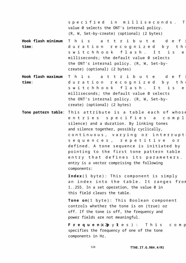
Figure 11.1-1 illustrates the negotiation and the exchange of messages in one or the other message formats.
Figure 11.1-1 OMCI message set negotiation
If the OLT has a priori knowledge that the ONT supports the extended message set, it may choose to omit the query step. However, an ONT may not transmit extended messages, including autonomous notifications, until it has received at least one extended message from the OLT during the current session (since initialization or re-ranging on the PON).
TTAE.IT.G.984.4/R1528
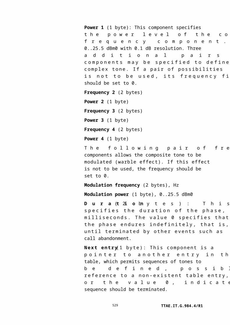
NOTE – It is anticipated that the baseline message format will be deprecated or removed from the
ITU-T G.987 Recommendations. ITU-T G.984 systems are therefore encouraged to use the extended
message set if they support it.
11.2 Packet format
Each OMCI protocol packet is encapsulated directly in one GEM frame, which may be fragmented in accordance with normal fragmentation rules. The GEM frame header contains the port ID of the OMCC for the addressed ONT, with a header PTI of 000 or 001.
Two message formats are defined, a baseline format and an extended format. The following clauses discuss the details.
The baseline packet format is shown in Figure 11.2-1. This fixed length 48-byte format reflects the ATM heritage of PON.
Transaction
correlation
identifier
(2 bytes)
Message
type
(1 byte)
Device
identifier
(1 byte)
Message
identifier
(4 bytes)
Message
contents
(32 bytes)
OMCI trailer
(8 bytes)
Figure 11.2-1 ONT management and control protocol baseline packet format
Figure 11.2-2 shows the extended packet format. The packet has variable length, up to 1980 bytes.
Transaction
correlation
identifier
(2 bytes)
Message
type (1 byte)
Device
identifier
(1 byte)
Message
identifier
(4 bytes)
Message
contents
length
(2 bytes)
Message
contents
(variable)
CRC
(4 bytes)
Figure 11.2-2 ONT management and control protocol extended packet format
The following clauses specify each field of these messages.
11.2.1 Transaction correlation identifier
The transaction correlation identifier is used to associate a request message with its response message. For request messages, the OLT selects a transaction identifier. A response message carries the transaction identifier of the message to which it is responding. The transaction identifier of messages generated autonomously by the ONT is 0.
TTAE.IT.G.984.4/R1529

As explained in clause 11.4.1, and for the baseline message format only, the most significant bit of the transaction correlation identifier indicates the priority of the message. The following coding is used: 0 = low priority, 1 = high priority. The OLT decides whether a command should be executed with low or high priority. The extended message format does not recognize priorities.
The remainder of the transaction identifier may be arbitrary, but should be chosen to avoid the possibility of ambiguous responses from ONTs.
11.2.2 Message type
The message type field is subdivided into four parts. These are shown in Figure 11.2.2-1.
8 7 6 5 1
DB AR AK MT
Figure 11.2.2-1 Message type field subdivision
Bit 8, the most significant bit, is reserved (DB). This bit is always 0. This bit is not used in the baseline message format, but is available for possible future use in the extended message format.
Bit 7, acknowledge request (AR), indicates whether or not the message requires an acknowledgement. An acknowledgement is a response to an action request, not a link layer handshake. If an acknowledgement is expected, this bit is set to 1. If no acknowledgement is expected, this bit is 0. In messages sent by the ONT, this bit is always 0.
Bit 6, acknowledgement (AK), indicates whether or not this message is an acknowledgement to an action request. If a message is an acknowledgement, this bit is set to 1. If the message is not a response to a command, this bit is set to 0. In messages sent by the OLT, this bit is always 0.
Bits 5..1, message type (MT), indicate the message type, as defined in Table 11-1. Values not shown in the table are reserved.
TTAE.IT.G.984.4/R1530

Table 11-1 OMCI message types
MT Type Purpose AKIncrement
MIBdata sync
4 Create Create a managed entity instance with its
attributes
Yes Yes
6 Delete Delete a managed entity instance Yes Yes
8 Set Set one or more attributes of a managed entity Yes Yes
9 Get Get one or more attributes of a managed entity Yes No
11 Get all alarms Latch the alarm statuses of all managed entities
and reset the alarm message counter
Yes No
12 Get all alarms next Get the active alarm status of the next managed
entity
Yes No
13 MIB upload Latch the MIB Yes No
14 MIB upload next Get latched attributes of a managed entity
instance
Yes No
15 MIB reset Clear the MIB, re-initialize it to its default, and
reset the MIB data sync counter to 0
Yes No
16 Alarm Notification of an alarm No No
17 Attribute value
change
Autonomous notification of an attribute value
change
No No
18 Test Request a test on a specific managed entity Yes No
19 Start software
download
Start a software download action Yes Yes
20 Download section Download a section of a software image (Not
e)
No
21 End software
download
End of a software download action Yes Yes
22 Activate software Activate the downloaded software image Yes Yes
23 Commit software Commit the downloaded software image Yes Yes
24 Synchronize time Synchronize the time between OLT and ONT Yes No
25 Reboot Reboot ONT or circuit pack Yes No
TTAE.IT.G.984.4/R1531

Table 11-1 OMCI message types
MT Type Purpose AKIncrement
MIBdata sync
26 Get next Get the latched attribute values of the managed
entity within the current snapshot
Yes No
27 Test result Notification of result initiated by a test
command
No No
28 Get current data Get current counter value associated with one
or more attributes of a managed entity
Yes No
29 Set table Set one or more rows of a table Yes Yes
NOTE – The download section action is acknowledged only for the last section within a window.
See clause I.2.7.
11.2.3 Device identifier
In baseline OMCI messages, this field is defined to be 0x0A.
In extended OMCI messages, this field is defined to be 0x0B.
11.2.4 Managed entity identifier
The message identifier consists of four bytes. The first, most significant, two bytes of the message identifier field are used to indicate which managed entity is the target of the action specified in the message type. The maximum number of possible managed entities is thus 65535. The least significant two bytes of this message identifier field are used to identify the managed entity instance. The number of bytes for each managed entity instance is defined in clause 9. The summation of the number of bytes in the message identifier field and the number of bytes available in the message contents field shall be 36 bytes because the ONT management and control protocol packet format is 53 bytes long.
Table 11-2 gives the managed entities and their class values in the OMCI. Depending on the managed entity, there will be only one (e.g., ONT-G) or several (e.g., MAC bridge port config data) instances in an ONT. Note that this table contains all the managed entities ever standardized for OMCI, including ITU-T G.983-series and ATM features now deprecated, because all these class values will remain reserved forever. The class values defined in the ITU-T G.983-series were only one byte, and so they are padded with a leading 0x00 byte to make them two-byte values usable in G-PON.
TTAE.IT.G.984.4/R1532

Table 11-2 – Managed entity class identifiers
Managed entity class value
Managed entity
1 ONTB-PON
2 ONT data
3 PON IF line cardholder
4 PON IF line card
5 Cardholder
6 Circuit pack
7 Software image
8 UNIB-PON
9 TC AdapterB-PON
10 Physical path termination point ATM UNI
11 Physical path termination point Ethernet UNI
12 Physical path termination point CES UNI
13 Logical N × 64 kbit/s sub-port connection termination point
14 Interworking VCC termination point
15 AAL1 profileB-PON
16 AAL5 profile
17 AAL1 protocol monitoring history dataB-PON
18 AAL5 performance monitoring history data
19 AAL2 profile
20 --------------------------(Intentionally left blank)
21 CES service profile-G
22 (Reserved)
23 CES physical interface performance monitoring history data
24 Ethernet performance monitoring history data
25 VP network CTP
26 ATM VP cross-connection
27 Priority queueB-PON
TTAE.IT.G.984.4/R1533

Table 11-2 – Managed entity class identifiers
Managed entity class value
Managed entity
28 DBR/CBR traffic descriptor
29 UBR traffic descriptor
30 SBR1/VBR1 traffic descriptor
31 SBR2/VBR2 traffic descriptor
32 SBR3/VBR3 traffic descriptor
33 ABR traffic descriptor
34 GFR traffic descriptor
35 ABT/DT/IT traffic descriptor
36 UPC disagreement monitoring history dataB-PON
37 --------------------------(intentionally left blank)
38 ANI
39 PON TC adapter
40 PON physical path termination point
41 TC adapter protocol monitoring history data
42 Threshold dataB-PON
43 Operator specific
44 Vendor specific
45 MAC bridge service profile
46 MAC bridge configuration data
47 MAC bridge port configuration data
48 MAC bridge port designation data
49 MAC bridge port filter table data
50 MAC bridge port bridge table data
51 MAC bridge performance monitoring history data
52 MAC bridge port performance monitoring history data
53 Physical path termination point POTS UNI
54 Voice CTP
TTAE.IT.G.984.4/R1534

Table 11-2 – Managed entity class identifiers
Managed entity class value
Managed entity
55 Voice PM history data
56 AAL2 PVC profileB-PON
57 AAL2 CPS protocol monitoring history dataB-PON
58 Voice service profile
59 LES service profile
60 AAL2 SSCS parameter profile1
61 AAL2 SSCS parameter profile2
62 VP performance monitoring history data
63 Traffic scheduler
64 T-CONT buffer
65 UBR+ traffic descriptor
66 AAL2 SSCS protocol monitoring history dataB-PON
67 IP port configuration data
68 IP router service profile
69 IP router configuration data
70 IP router performance monitoring history data 1
71 IP router performance monitoring history data 2
72 ICMP performance monitoring history data 1
73 ICMP performance monitoring history data 2
74 IP route table
75 IP static routes
76 ARP service profile
77 ARP configuration data
78 VLAN tagging operation configuration data
79 MAC bridge port filter preassign table
80 Physical path termination point ISDN UNI
81 (Reserved)
TTAE.IT.G.984.4/R1535

Table 11-2 – Managed entity class identifiers
Managed entity class value
Managed entity
82 Physical path termination point video UNI
83 Physical path termination point LCT UNI
84 VLAN tagging filter data
85 ONUB-PON
86 ATM VC cross-connection
87 VC network CTPB-PON
88 VC PM history data
89 Ethernet performance monitoring history data 2
90 Physical path termination point video ANI
91 Physical path termination point 802.11 UNI
92 802.11 station management data 1
93 802.11 station management data 2
94 802.11 general purpose object
95 802.11 MAC and PHY operation and antenna data
96 802.11 performance monitoring history data
97 802.11 PHY FHSS DSSS IR tables
98 Physical path termination point xDSL UNI part 1
99 Physical path termination point xDSL UNI part 2
100 xDSL line inventory and status data part 1
101 xDSL line inventory and status data part 2
102 xDSL channel downstream status data
103 xDSL channel upstream status data
104 xDSL line configuration profile part 1
105 xDSL line configuration profile part 2
106 xDSL line configuration profile part 3
107 xDSL channel configuration profile
108 xDSL subcarrier masking downstream profile
TTAE.IT.G.984.4/R1536

Table 11-2 – Managed entity class identifiers
Managed entity class value
Managed entity
109 xDSL subcarrier masking upstream profile
110 xDSL PSD mask profile
111 xDSL downstream RFI bands profile
112 xDSL xTU-C performance monitoring history data
113 xDSL xTU-R performance monitoring history data
114 xDSL xTU-C channel performance monitoring history data
115 xDSL xTU-R channel performance monitoring history data
116 TC adaptor performance monitoring history data xDSL
117 Physical path termination point VDSL UNI
118 VDSL VTU-O physical data
119 VDSL VTU-R physical data
120 VDSL channel data
121 VDSL line configuration profile
122 VDSL channel configuration profile
123 VDSL band plan configuration profile
124 VDSL VTU-O physical interface monitoring history data
125 VDSL VTU-R physical interface monitoring history data
126 VDSL VTU-O channel performance monitoring history data
127 VDSL VTU-R channel performance monitoring history data
128 Video return path service profile
129 Video return path performance monitoring history data
130 802.1p mapper service profile
131 OLT-G
132 Multicast interworking VCC termination point
133 ONT power shedding
134 IP host config data
135 IP host performance monitoring history data
TTAE.IT.G.984.4/R1537
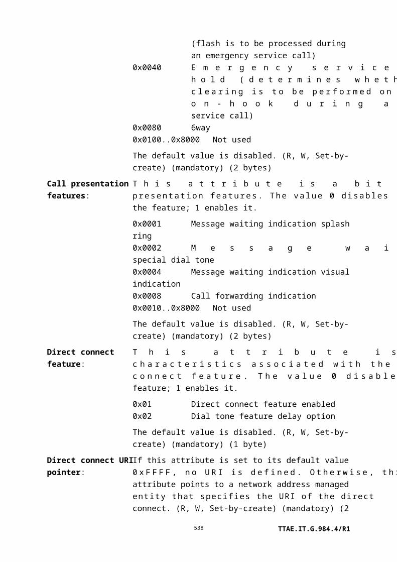
Table 11-2 – Managed entity class identifiers
Managed entity class value
Managed entity
136 TCP/UDP config data
137 Network address
138 VoIP config data
139 VoIP voice CTP
140 Call control performance monitoring history data
141 VoIP line status
142 VoIP media profile
143 RTP profile data
144 RTP performance monitoring history data
145 Network dial plan table
146 VoIP application service profile
147 VoIP feature access codes
148 Authentication security method
149 SIP config portal
150 SIP agent config data
151 SIP agent performance monitoring history data
152 SIP call initiation performance monitoring history data
153 SIP user data
154 MGC config portal
155 MGC config data
156 MGC performance monitoring history data
157 Large string
158 ONT remote debug
159 Equipment protection profile
160 Equipment extension package
161 Port mapping package (B-PON only; use 297 for G-PON)
162 Physical path termination point MoCA UNI
TTAE.IT.G.984.4/R1538

Table 11-2 – Managed entity class identifiers
Managed entity class value
Managed entity
163 MoCA Ethernet performance monitoring history data
164 MoCA interface performance monitoring history data
165 VDSL2 line configuration extensions
166 xDSL line inventory and status data part 3
167 xDSL line inventory and status data part 4
168 VDSL2 line inventory and status data part 1
169 VDSL2 line inventory and status data part 2
170 VDSL2 line inventory and status data part 3
171 Extended VLAN tagging operation configuration data
172..239 Reserved for future B-PON managed entities
240-255 Reserved for vendor-specific managed entities
256 ONT-G
257 ONT2-G
258 ONU-G
259 ONU2-G
260 PON IF line card-G
261 PON TC adapter-G
262 T-CONT
263 ANI-G
264 UNI-G
265 ATM interworking VCC termination point
266 GEM interworking termination point
267 GEM port performance monitoring history data
268 GEM port network CTP
269 VP network CTP-G
270 VC network CTP-G
271 GAL TDM profile
TTAE.IT.G.984.4/R1539

Table 11-2 – Managed entity class identifiers
Managed entity class value
Managed entity
272 GAL Ethernet profile
273 Threshold data 1
274 Threshold data 2
275 GAL TDM performance monitoring history data
276 GAL Ethernet performance monitoring history data
277 Priority queue-G
278 Traffic scheduler-G
279 Protection data
280 Traffic descriptor (Note – Formerly GEM traffic descriptor)
281 Multicast GEM interworking termination point
282 Pseudowire termination point
283 RTP pseudowire parameters
284 Pseudowire maintenance profile
285 Pseudowire performance monitoring history data
286 Ethernet flow termination point
287 OMCI
288 Managed entity
289 Attribute
290 Dot1X port extension package
291 Dot1X configuration profile
292 Dot1X performance monitoring history data
293 Radius performance monitoring history data
294 TU CTP
295 TU performance monitoring history data
296 Ethernet performance monitoring history data 3
297 Port mapping package-G
298 Dot1 rate limiter
TTAE.IT.G.984.4/R1540

Table 11-2 – Managed entity class identifiers
Managed entity class value
Managed entity
299 Dot1ag maintenance domain
300 Dot1ag maintenance association
301 Dot1ag default MD level
302 Dot1ag MEP
303 Dot1ag MEP status
304 Dot1ag MEP CCM database
305 Dot1ag CFM stack
306 Dot1ag chassis-management info
307 Octet string
308 General purpose buffer
309 Multicast operations profile
310 Multicast subscriber config info
311 Multicast subscriber monitor
312 FEC performance monitoring history data
313 RE ANI-G
314 Physical path termination point RE UNI
315 RE upstream amplifier
316 RE downstream amplifier
317 RE config portal
318 File transfer controller
319 CES physical interface performance monitoring history data 2
320 CES physical interface performance monitoring history data 3
321 Ethernet frame performance monitoring history data downstream
322 Ethernet frame performance monitoring history data upstream
323 VDSL2 line configuration extensions 2
324 xDSL impulse noise monitor performance monitoring history data
325 xDSL line inventory and status data part 5
TTAE.IT.G.984.4/R1541

Table 11-2 – Managed entity class identifiers
Managed entity class value
Managed entity
326 xDSL line inventory and status data part 6
327 xDSL line inventory and status data part 7
328 RE common amplifier parameters
329 Virtual Ethernet interface point
330 Generic status portal
331 ONT-E
332 Enhanced security control
333 MPLS pseudowire termination point
334-65279 Reserved for future standardization
65280-65535 Reserved for vendor-specific use
11.2.5 Message contents length, extended message format
These two bytes contain the length, in bytes, of the message contents field. Its value lies between 0 and 1966, for a 1980-byte PDU limit.
Eleven bits suffice to specify this range. The five most significant bits of this field are reserved for future use.
11.2.6 Message contents
The layout of the message contents field is message specific. The detailed layout of all messages appears in Appendix II.
11.2.7 OMCI trailer, baseline message format
The AAL5 trailer definition is reused in this field. The eight bytes of this field are as follows:
a) The first two bytes correspond to CPCS-UU and CPI. They are set to 0 at the transmitter and ignored at the receiver.
b) The length of the CPCS-SDU field is set to 0x0028 (40 decimal).
c) The 32-bit CRC is as specified in [ITU-T I.363.5].
11.2.8 CRC, extended message format
The integrity of the extended message format is verified by this four-byte field, a 32-bit CRC as specified in [ITU-T I.363.5].
TTAE.IT.G.984.4/R1542

11.2.9 Message limits
Baseline OMCI messages impose limits on the size of attributes. Table 11-3 lists the important limits.
Table 11-3 – OMCI baseline message limitations
Item Limited by Maximum size, bytes
Total size of set-by-create attributes (including ME ID) Create 34
Size of (R) or (R,W) simple attribute Get response 25
Size of (R) or (R,W) structured table entry (Note) Set 30
Total size of a get Get response 25
Total size of a get current data Get current data response 25
NOTE – A structured table is one that contains distinct and separable rows, each row of which has the same syntax as the others. Long strings of bytes are also designated tables in clause 9, because the mechanism for retrieval is the same: get, followed by a number of get next commands. Such a byte string could be regarded as a table with but a single row, the length of which is limited only by the number of get next commands that can be specified. There is no way to set a value into such a byte string, however, so these attributes are necessarily read-only.
Extended messages are limited by the total size of the PDU. For backward compatibility, attribute definitions remain within the size limits of baseline messages, but more attributes may be contained within a single extended message. The following considerations apply to baseline messages only. The larger PDU eliminates the possibility of message length violation in the extended message set.
It is important that OLT and ONT implementations take size limits into account. For example, it is easy to form a (baseline) get command that asks the ONT to return more attributes than can fit into a (baseline) get response message. If the OLT asks for too many attributes in a get request, the ONT may respond with as many attributes as fit into the space available. From the attribute-present mask, the OLT can parse the attributes that were sent correctly, and can issue another get to retrieve the attributes that did not fit.
While this is the preferred behaviour, an alternate interpretation may be that the ONT would return a parameter error code when it receives a (baseline) get request whose response does not completely fit into one (baseline) get response message. For the sake of interoperability, the expected behaviour between an OLT and ONT with different interpretations is provided below:
Case 1:
TTAE.IT.G.984.4/R1543

The ONT reports a parameter error, and the OLT expects a partial list. If this happens, the OLT should react by simplifying its get request. The ONT then responds without an error.
Case 2:
The ONT provides a partial list, while the OLT expects to get an error. The OLT receives a normal message and processes it normally. The OLT asks again for any attributes it did not get.
11.2.10 Test result enumeration
Test actions can return measurements of various physical parameters in vendor-specific ways. Table 11-4 identifies parameters that may be of interest, with enumerated values to represent them in the test response message defined in Appendix II.
The resolution shown in the following descriptions merely indicates the weight attached to the least significant bit, and is not intended to impose requirements for precision or accuracy of the measured value.
Table 11-4 – Codes to represent measured values
Type Parameter Representation
1 Power feed voltage, V DC voltage, 2s complement, 20 mV resolution
2 Low voltage, V DC voltage, 2s complement, 100 µV resolution
3 Received optical power, dB dBµW, 2s complement, 0.002 dB resolution
4 Received optical power, W Power, unsigned integer, 0.1 µW resolution
5 Transmitted optical power, dB dBµW, 2s complement, 0.002 dB resolution
6 Transmitted optical power, W Power, unsigned integer, 0.1 µW resolution
7 Video level, dB dBmV, 2s complement, 0.002 dB resolution
8 Video level, V RF voltage, unsigned integer, 200 µV
resolution. May be filtered or weighted in
accordance with vendor-specific needs.
9 Laser bias current Unsigned integer, 2 µA resolution
10 Received signal quality measure Q Unsigned integer, resolution 0.1
11 Signal to noise ratio, dB Unsigned integer, resolution 0.1 dB
12 Temperature, degrees C 2s complement, 1/256 degree C resolution
13..239 Reserved for future standardization
240-254 Not to be standardized, available for
vendor use
TTAE.IT.G.984.4/R1544

255 Reserved Indicates an unavailable field in an ordered list
of response values
11.3 Message flow control and error recovery
NOTE – Prioritized message handling is defined only for the baseline message set. In the context of
the extended message set, this clause should be read with the understanding that there is only one
priority class.
The flow control/error recovery procedures for message exchange over the OMCC are based on a simplex acknowledged transaction stop-and-wait mechanism that can be extended to support concurrent execution of multiple transaction requests of different priority levels. These flow control procedures ensure that a low level acknowledged transaction request transmitted from the OLT has been properly received and processed to completion by the ONT before the next message of the same priority level is sent by the OLT. The stop-and-wait protocol uses the transaction correlation identifier field, retry counter(s), and applicable transaction request timer(s) to control the message flow rate while relying on a CRC calculation to verify the data integrity of all received messages.
A transaction request timer Ti with expiration time Tmaxi is started when a transaction request message of priority level i is sent to an ONT, and is stopped upon receipt of an acknowledgement message containing the same transaction correlation identifier value. If a valid acknowledgement message is not received by the OLT after timer Ti expires, the OLT re-sends the original transaction request message.
A retransmitted acknowledged transaction request message carries the same transaction correlation ID as the original message. Each time an acknowledged transaction request message is retransmitted by the OLT, the transmitter increments the retry counter R i (the counter associated with priority level i acknowledged transaction requests). When a retry counter Ri (initialized to 0 upon the first transmission of each new command) reaches the maximum retry value, Rmaxi, the transmitter stops re-transmitting the message and declares an OMCC link state error.
These timers (Ti) and retry counters (Ri) are only maintained within the OLT controller and do not exist within the ONT. Threshold values for timer expiration (Tmaxi) and number of retries (Rmaxi) are not subject to standardization. It is suggested that the default threshold values of both Tmax and Rmax be independently configurable for each priority level. The default value for Tmax1 (i.e., high priority threshold) should account for the typical message transmission delay plus the command message response time.
These flow control/error recovery procedures are illustrated in Figure 11.3-1 for a case where the OMCC link is not permanently broken. First the OLT sends an acknowledged transaction request (message 1) with priority level 0. Subsequently (while message 1 is still outstanding), the OLT issues an additional acknowledged transaction request (message 2) with priority
TTAE.IT.G.984.4/R1545

level 1. Both of these commands are received and executed with the associated response (acknowledgement messages) returned to the OLT by the ONT. The acknowledgement for message 1 is received by the OLT in time; however, the response to message 2 is lost and never received. The OLT detects that something went wrong because timer T1 expires, and the OLT therefore retransmits the original command (message 2). From the identical transaction ID, the ONT detects that this retransmitted command is identical to the last received command (for priority level 1) and therefore does not re-execute it. The ONT simply retransmits the original response from the previous execution of message 2, which reaches the OLT in time.
The final transaction in the example is the case where the OLT sends an acknowledged transaction request (message 3) with priority level 0, but the message itself gets lost and is never properly received by the ONT. After the associated timer (T0) expires, the OLT retransmits the command and now all goes well.
Figure 11.3-1 Concurrent message exchange with error recovery
A case where the OMCC link is effectively broken (link down) is shown in Figure 11.3-2.
TTAE.IT.G.984.4/R1546

Figure 11.3-2 OMCC link error detection
11.4 OMCI handling within the ONT
11.4.1 Prioritized protocol entities
NOTE – Prioritized message handling is defined only for the baseline message set. In the context of
the extended message set, this clause should be read with the understanding that there is only one
priority class.
This clause specifies the behaviour of the ONT more precisely than in the preceding clause with respect to the prioritized request mechanism of the OMCC.
Conceptually, the way the ONT handles the OMCC requests can be illustrated by referring to the dual priority level implementation example shown in Figure 11.4.1-1.
When the ONT receives a GEM frame via the GEM port associated with the management channel, it shall calculate the CRC and compare it with the value found in the OMCI trailer. If the values do not match, the ONT shall discard the message. It is recommended that this event be logged by the ONT and possibly communicated to the OLT by some out-of-band mechanism but, as far as the protocol is concerned, the message is discarded silently.
Messages with a correct CRC are then placed into either of two distinct incoming FIFO-based message queues, according to the high or low priority level of the associated command
TTAE.IT.G.984.4/R1547

encoded in the most significant bit of the transaction correlation identifier field. If the associated incoming message queue is already full, the ONT must simply discard the message. It is recommended that this event be logged by the ONT and possibly communicated to the OLT by some out-of-band mechanism but, as far as the protocol is concerned, the message is discarded silently.
There are two distinct incoming command processing protocol entities, one associated with each priority level, that serve messages sequentially from independent incoming FIFO queues. Each protocol entity can execute concurrently. If a message is a one-way (unacknowledged) command, the protocol entity simply executes the command. If a message is an acknowledged command, the protocol entity must first look at the transaction correlation identifier. If it is not equal to the transaction correlation identifier of the last executed command with the same priority level, the protocol entity executes the command and places the response/acknowledgement, with an identical transaction correlation identifier, in the outgoing FIFO queue of the same priority level. If the transaction correlation identifier is equal to that of the last executed command with the same priority level (the case where the OLT retransmits a command due to lack of proper acknowledgement), the protocol entity does not actually execute the command but simply places the response from the last execution of that command in the outgoing FIFO queue to re-send the previous acknowledgement response. In both cases, the command processing protocol entity for a given priority level should block until there is room in the associated outgoing FIFO queue for the response message.
In the other direction, requests by ONT applications to send autonomous event notifications simply result in the corresponding messages being directed to an event notification protocol entity for transmission to the OLT. The event notification protocol entity forwards these event notification messages to the low priority outgoing FIFO queue. In this case as well, the event notification protocol entity should block until there is room in the low priority outgoing FIFO queue to hold the notification message. The CRC generator removes messages from the outgoing FIFO queues using a strict priority discipline (that is, the low-priority queue is served only when the high-priority queue is empty), generates a CRC, formats the packet as either a baseline or an extended message, depending on which form is in use, and transmits the message to the OLT.
TTAE.IT.G.984.4/R1548

Figure 11.4.1-1 Protocol entities within the ONT
11.4.2 Restrictions on the actions in relation to the protocol entities
To reduce the complexity and the amount of memory necessary in the ONT, the OLT is not allowed to issue a MIB upload or a software download of a certain priority level while a similar action in the other priority level is in progress.
11.4.3 Use of the default alloc-ID
The OMCC is carried in the upstream in the default allocation ID. In some implementations, the default alloc-id is also used for user traffic, and is associated with a T-CONT ME. In these cases, the OMCC traffic is combined with the T-CONT traffic using a simple strict-priority multiplexing, with the OMCC having higher priority.
Appendix I
OMCI common mechanisms and services
TTAE.IT.G.984.4/R1549
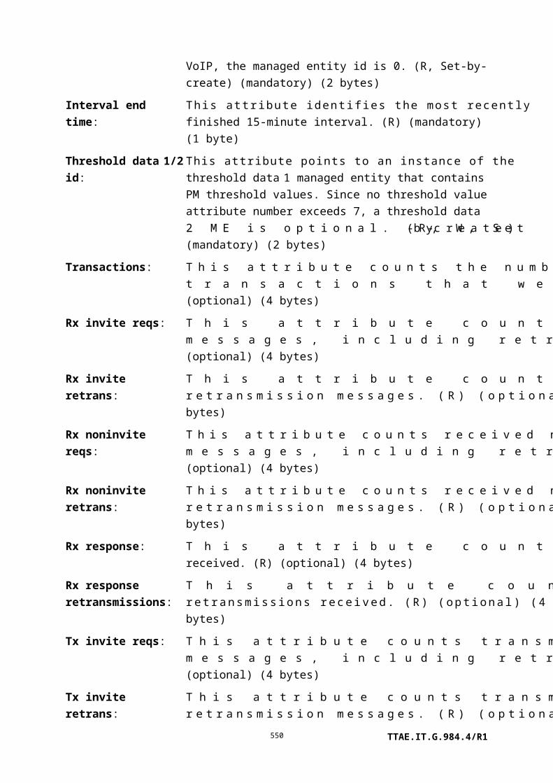
(This appendix does not form an integral part of this Recommendation)
This appendix describes the common mechanisms of OMCI, for example, MIB resynchronization, and OMCI services, for example, equipment management or connection management.
NOTE – Some information in this appendix should be modified appropriately when applied to
[ITU-T G.986].
I.1 Common mechanisms
The common mechanisms consist of:
a) MIB data sync increase.
b) MIB audit and resynchronization.
c) Alarm sequence number increase.
d) Alarm audit and resynchronization.
e) Get an attribute that is larger than the OMCI message contents field.
f) Create an instance of a managed entity with an attribute that is larger than the OMCI message contents field.
g) Reporting of test result.
h) Alarm reporting control.
These common mechanisms are explained with the aid of scenario diagrams.
I.1.1 MIB data sync increase
The revised content of this clause now appears in the G.984.4 implementers' guide [b-G.Imp984.4].
I.1.2 MIB audit and resynchronization
The revised content of this clause now appears in the G.984.4 implementers' guide [b-G.Imp984.4].
I.1.3 Alarm sequence number increase
The revised content of this clause now appears in the G.984.4 implementers' guide [b-G.Imp984.4].
I.1.4 Alarm audit and resynchronization
The revised content of this clause now appears in the G.984.4 implementers' guide [b-G.Imp984.4].
TTAE.IT.G.984.4/R1550

I.1.5 Table attributes
Normal attributes are coded such that they do not exceed the maximum OMCI attribute size, as limited by the baseline message format. However, there are cases where attributes need to be larger because they comprise arrays of data. In other cases, the attribute may be unstructured, but nevertheless be too large to be represented as a conventional attribute. Both types of large attributes are known as tables, and can be identified by the word table in their names.
A table entry may be short enough that more than one row would fit into a (baseline) set command. However, the set command has no deterministic way to specify how many such rows are present. Therefore, the set action is permitted to set only a single entry in the table, the size of which is specified in clause 9 for the particular attribute in question.
The set operation on a table row is possible only when individual table entries have a fixed size that does not exceed the maximum that can be conveyed in the (baseline) set message. A table attribute with variable-length rows or longer fixed-length rows is restricted to being read-only.
An optional set table command is defined in the extended message set. Functionally, the set table command is the equivalent of an ordered sequence of set commands, each directed to the same table attribute of a given managed entity. As with the set command, table rows must have fixed length, and because of the backward compatibility requirement, no table row may exceed the baseline length limit.
The actual size of any given table attribute instance at any given time may be smaller than the OMCI single-message limit. Regardless of its actual size, however, the following sequence governs the retrieval of all table attributes.
Figure I.1.5-1 shows how the OLT retrieves a table attribute. The OLT sends a get command, just as for any other attribute. The ONT latches a copy of the table for the anticipated get next sequence. In the get response, the ONT returns, not the value of the table attribute, but a four-byte field containing the table's size, expressed in bytes.
NOTE – Zero is a valid size for many table attributes.
The OLT then requests the attribute data from the ONT via the appropriate number of get next commands. There is no structure in the get next response; it simply regards the table as a byte string.
TTAE.IT.G.984.4/R1551

OLT ONT
The OLT requests the size of the attribute
Get_cmd[Any_ME][inst, attribute mask]
The ONT makes a copy of the attribute. The ONT responds to the request with the size of the attribute.
Get_rsp[Any_ME][inst, attribute mask, dataSize = X bytes]
The OLT requests the attribute data by sending the appropriate number of
GetNext commands.
GetNext_cmd[Any_ME][inst, attribute mask, SeqNumber =0]
GetNext_rsp[Any_ME][inst, attribute mask, 1st Y bytes of attribute data]
During the GetNext sequence, the ONTcan still send AVCs. When an AVC is received by
the OLT, the OLT updates its active MIB and marks the attributes changed.
During the GetNext sequence, the OLT can still send configuration commands.
When received by the ONT, the ONT updatesits active MIB and sends a response to the OLT.
GetNext_cmd[Any_ME][inst, attribute mask, SeqNumber =N [note]]
GetNext_rsp[Any_ME][inst, attribute mask, last Z bytes of attribute data]
NOTE – N+1 is the number of get next commands as derived by the OLT to retrieve the complete
table. For baseline OMCI messages, Y is 29 bytes; for extended OMCI messages, Y = 1966 Bytes
(1980 PDU size – 14 Bytes of OMCI header).
Figure I.1.5-1 Get a table attribute
The OLT issues as many get next requests as are needed to accommodate the size of the table attribute. The maximum time between two get next requests is 60 seconds. If the OLT does not send a get next request within this time after the previous get next request or after the initial get request, the ONT assumes the get attribute transaction has terminated, discards its copy of the table attribute, and denies further get next requests directed to that attribute.
TTAE.IT.G.984.4/R1552

Capturing snapshots of multiple large tables could exhaust the limited memory resources of the ONT. Within any one ONT, the OLT should get and get-next only one table attribute at a time. If more than one table attribute is selected in the get command attribute mask, the ONT may reject the command with an attribute failed or unknown result-reason code.
If more than one bit is set in the get next command attribute mask, or if the specified attribute is not a table, the ONT should respond with a parameter error result code.
In each get next command, the OLT generates a sequence number, starting from 0. The sequence number resets to 0 for each attribute, even if successive attributes are part of the same managed entity parent.
I.1.6 This clause intentionally left blank
(No subordinate text)
I.1.7 Report test result
Figure I.1.7-1 shows the scenario diagram for when the OLT requests that the ONT perform a test. The OLT requests that the ONT start testing by sending a "test" command. This command is acknowledged by a "test" response. Then, the ONT carries out the test. After the test is complete, the ONT reports the test result via a "test result" notification message. This scenario is used for the "self test" attribute of ONT-G managed entity or circuit pack managed entity. Moreover, this scenario may be useful for MLT tests or for additional tests that may be added in the future.
Figure I.1.7-1 – Reporting of test result
The ONT may also report a test result autonomously in cases where it performs routine background tests. An autonomous test report may be identified by the fact that its transactions identifier is 0. An autonomous test report normally occurs only when some measured value is out of tolerance, and may therefore be reported in conjunction with an alarm.
TTAE.IT.G.984.4/R1553

I.1.8 Alarm reporting control
Alarm reporting control allows for the suppression of alarms from physical path termination points and cardholders, under the control of the management system. [ITU-T M.3100] completely describes ARC from a generic viewpoint. OMCI provides for ARC functions using two attributes of the parent managed entity: ARC and ARC_interval. These two attributes are described below.
ARC
This attribute allows the activation of alarm reporting control (ARC) for this PPTP or cardholder. The attribute works in concert with the ARC_interval attribute. A value of 0 indicates disabled, while a value of 1 indicates enabled. The default value is disabled. When the ARC attribute is set to disabled, the PPTP or cardholder is in the ITU-T M.3100 ALM state. Alarms are reported normally in the ALM state. When the ARC attribute is set to enabled, the PPTP or cardholder is in the ITU-T M.3100 NALM-QI state, in which alarms are suppressed.
The PPTP or cardholder moves from state ALM to state NALM-QI when the OLT changes the ARC attribute to enabled. The PPTP or cardholder moves from the NALM-QI state to the ALM state when either 1) the PPTP or cardholder is trouble free and the ARC_interval timer expires, or 2) the ARC attribute is set to disabled by the OLT. Continuation or recurrence of a fault resets the timer. If the ARC_interval timer expires, the ONT sets the ARC attribute to disabled autonomously, and sends an AVC to notify the OLT. Refer to [ITU-T M.3100] for a more extensive discussion.
The ARC_interval attribute can assume normal timing values of 0 to 254 minutes. The value 0 implies that a PPTP or cardholder in the NALM-QI state goes immediately to the ALM state upon detection of a problem-free state. An ARC_interval value of 255 has the special meaning that the timer never expires. The PPTP or cardholder remains in the NALM-QI state until the OLT sets the ARC attribute to disabled. This behaviour is equivalent to the NALM state, which is another generic behaviour of the ARC function in [ITU-T M.3100].
Note that there is no support for the NALM-TI sub-function in the OMCI system. (R,W) (optional) (1 byte)
ARC_interval
This attribute defines the interval to be used with the ARC function for this PPTP. The values 0 through 254 give the duration in minutes for the NALM-QI timer. The special value 255 means that the timer never expires. The default value is zero. (R, W) (optional) (1 byte)
ARC suppresses alarm reporting on the parent managed entity and all dependent entities, but does not suppress the alarm conditions themselves. Therefore, if an alarm condition develops
TTAE.IT.G.984.4/R1554

during an ARC interval, the ONT should maintain the internal indication of the alarm, and if the OLT gets all alarms regardless of ARC, it should be reported.
This Recommendation defines a number of performance monitoring managed entities. They share a number of characteristics, as described here. Exceptions to the generic behaviour are defined in the specific managed entity affected. Two groups of performance monitoring (PM) managed entities are defined:
1) Classical PM, whose members are identified by names containing the string, "performance monitoring history data."
2) Extended PM, whose members are identified by names containing the string, "extended PM."
The remainder of this clause describes behaviour common to the two classes of PM MEs. The subclauses then discuss aspects unique to each PM ME class.
All PM managed entities are created and deleted by the OLT.
Classical PM, and optionally extended PM, are based on the assumption of a continuing sequence of 15-minute intervals. This sequence of 15-minute intervals is synchronized by the synchronize time action, issued by the OLT against the ONT-G managed entity. The synchronize time action establishes a 15-minute tick boundary and starts numbering the intervals from 0. The interval number is returned in the interval end time attribute. In the PM ME template, the interval end time is a single byte, which rolls over from 255 to 0.
The synchronize time action is the only mechanism guaranteed to reset either the phase or the interval number. For example, neither ONT re-boot nor MIB reset can be expected to have these effects (the performance monitoring consequence of the latter events is undefined). In the absence of a synchronize time message, an ONT would be expected to maintain 15-minute intervals asynchronously with the outside world, and with arbitrary interval end-time identifiers.
The ONT performs no archival; archival is the function of the OLT or a management system. In a 15-minute accumulation mode, the ONT conceptually has only two storage bins: a current accumulator and a history bin. At 15-minute intervals, they switch roles. History is discarded at age thirty minutes, when the previous history bin is initialized into its role as the new current accumulator. The previous accumulator, now in its role as the history bin, retains its totals for 15 minutes, so that the OLT can upload them if desired.
In a 15-minute accumulation mode, the get action on a PM managed entity returns the values of attributes in the history bin. An ONT may also support an optional action in this mode, get current data. The effect of this action is to return the value of attributes in the current accumulator. When a PM attribute is an average, it acquires a value only at the close of a 15-minute interval. The value returned by a get current data operation is undefined (0xFF in every byte would be reasonable).
TTAE.IT.G.984.4/R1555

OMCI supports PM thresholds and threshold crossing alerts (TCAs). Not all PM attributes need to be thresholded; threshold definition and assignment is part of the specification of each PM attribute.
Most performance attributes are counters. During the accumulation interval, the PM managed entity collects counter statistics in accordance with each PM attribute definition, and continuously compares the accumulated values with any thresholds that may exist. When an accumulated value first equals or exceeds the threshold, the ONT originates a TCA. At the end of the current 15-minute interval, the ONT issues a second TCA, cancelling the first.
If a counter PM attribute should fill up during the interval, it remains at its maximum possible value, rather than rolling over.
When a PM attribute is an average, its value is computed only at the end of the interval. A TCA on such an attribute can therefore be declared only at the end of the interval. The TCA would then be immediately cleared as the accumulator was reset for the next interval. The definition of a given PM attribute may specify different or more detailed behaviour.
When a PM attribute is a high-water mark, a TCA is declared when the monitored parameter equals or exceeds the threshold value from below; conversely for a low-water mark attribute. There is no general definition of the mechanism to clear the TCA, nor specification of delay or hysteresis to avoid TCA storms for a parameter fluctuating near the threshold value. These should be defined in the specification of each PM attribute.
It should be noted that TCAs are reported in OMCI alarm messages. There is no overlap between TCA codepoints and alarm codepoints, because a given ME class declares either alarms or TCAs, but not both.
Even when thresholding is defined on a PM managed entity, it is the option of the OLT whether to provision it (see clause I.1.10 regarding optional pointers). The PM managed entity template includes a placeholder for a pointer to an instance of the threshold data 1/2 managed entities. Threshold configuration is performed by means of threshold data MEs, which are created and deleted by the OLT. If no assigned threshold attribute number exceeds seven in a PM ME's definition, the existence of a threshold data 2 ME is optional.
The control block of a PM ME contains persistent data that can be set by the OLT. Setting the value of a control block attribute therefore increments MIB sync. In addition, the control block attribute of a PM ME is included in MIB upload. Other PM attributes are transient and are not included in MIB uploads.
Template for the definition of a PM ME
Existing PM generally follows the outline below. Significant exceptions are discussed here; an implementation is advised to be aware that the definitions of individual MEs and attributes may contain other exceptions.
TTAE.IT.G.984.4/R1556

<Description>
Relationships
<Relationships>
Attributes
Managed entity id: This attribute is discussed further in the separate clauses below.
Interval end time: This attribute identifies the most recently finished 15-minute interval. (R) (mandatory) (1 byte)
Control block: This attribute is discussed further in the separate clauses below. In classical PM, it is just a pointer to threshold data MEs
PM1: Definition of first PM accumulation attribute, in most cases a counter, in other cases, an average, a high-water mark or a low-water mark. Four bytes is the recommended size of a PM accumulation attribute, but definitions vary. (R) (mandatory) (4 bytes)
PM2…: Definition of additional PM accumulation attributes, maximum not to exceed 14. There is no particular preference on the order in which parameters are defined
Actions
Create, delete, get, set
get current data (optional)
Notifications
Threshold crossing alert
Number Threshold crossing alert Threshold data counter # (Note)
1 PM1 1
2 PM2 2
3 … 3
4 4
NOTE – This number associates the TCA with the specified threshold value attribute of the
threshold data 1 managed entity.
The Threshold crossing alert column lists thresholded parameters in order. The Number column merely identifies a row in the table and should not be considered significant.
The Threshold data counter column assigns threshold attributes of the threshold data 1 and if required, the threshold data 2 MEs. In all cases, the assignment is monotonic, but existing PM
TTAE.IT.G.984.4/R1557

definitions may or may not skip a threshold attribute for each PM attribute that is to be thresholded. In future PM definitions, it is recommended that threshold attributes be assigned sequentially, without gaps. If, for example, the only thresholded PM attributes were the first, third and sixth in order of PM ME definition, they would still be assigned threshold attributes 1, 2, 3.
I.1.9.1 Classical PM
In classical PM, the managed entity ID attribute takes the same value as the parent managed entity's ME ID, so that no explicit pointer to the parent ME is required. The ME class of the parent is fixed in the definition of the classical PM ME.
Managed entity id: This attribute uniquely identifies each instance of this managed entity. Through an identical ID, this managed entity is implicitly linked to an instance of a <parent managed entity class>. (R, Set-by-create) (mandatory) (2 bytes)
In classical PM, the control block attribute is always a simple pointer to a threshold data ME, and is designated as such. The attribute value may be set to a null pointer if no thresholding is desired. If no assigned threshold number exceeds 7, it is the OLT's option whether to create a threshold data 2 ME or not. The template text reads as follows, depending on the highest threshold attribute assigned:
Threshold data 1/2 id:
This attribute points to an instance of the threshold data 1 and 2 managed entities that contains PM threshold values. (R, W, Set-by-create) (mandatory) (2 bytes)
Or:
Threshold data 1/2 id:
This attribute points to an instance of the threshold data 1 managed entity that contains PM threshold values. Since no threshold value attribute number exceeds 7, a threshold data 2 ME is optional. (R, W, Set-by-create) (mandatory) (2 bytes)
I.1.9.2 Extended PM
In extended PM, the control block attribute is defined to be (R, W, Set-by-create) (mandatory) (16 bytes). The template for these 16 bytes is as follows:
Threshold data
1/2 id: (2 bytes)The definition of this field is the same as that in classical PM. When PM is collected on a continuously-running basis, rather than in 15-minute intervals, counter thresholds should not be established. There is no mechanism to clear a TCA, and any counter parameter may eventually be expected to cross any given threshold value
Parent ME class: (2 bytes)
This field contains the enumerated value of the ME class of the PM ME's parent. Together with the parent ME instance field, this permits a
TTAE.IT.G.984.4/R1558

given PM ME to be associated with any OMCI ME. The definition of an extended PM ME should list the allowed parent ME classes
Parent ME instance: (2 bytes)
This field identifies the specific parent ME instance to which the PM ME is attached
Accumulation disable: (2 bytes)
This bit field allows PM accumulation to be disabled; refer to table xx-x. The default value 0 enables PM collection. If bit 15 is set to 1, no PM is collected by this ME instance. If bit 15 = 0 and any of bits 14..1 are set to 1, PM collection is inhibited for the attributes indicated by the 1 bits. Inhibiting PM collection does not change the value of a PM attribute, but if PM is accumulated in 15-minute intervals, the value is lost at the next 15-minute interval boundary.
Bit 16 is an action bit that always reads back as 0. When written to 1, it resets all PM attributes in the ME, and clears any TCAs that may be outstanding.
Table xx-x – Bit assignments in extended PM control block
Bit 16 15 1413
...
3 21 (LSB)
Accumulation disable
Global clear
Global disable
PM14
… … PM2
PM1
TCA disable Global disable
Th14 … … Th2 Th1
TCA disable: (2 bytes)
Also clarified in table xx-x, this field permits TCAs to be inhibited, either individually or for the complete managed entity instance. As with the accumulation disable field, the default value 0 enables TCAs, and setting the global disable bit overrides the settings of the individual thresholds. Unlike the accumulation disable field, the bits are mapped to the thresholds defined in the associated threshold data 1 and 2 ME instances. When the global or attribute-specific value changes from 0 to 1, outstanding TCAs are cleared, either for the ME instance globally or for the individual disabled threshold. These bits affect only notifications, not the underlying parameter accumulation
TTAE.IT.G.984.4/R1559

or storage.
If the threshold data 1/2 id attribute does not contain a valid pointer, this field is not meaningful.
Thresholds should be used with caution if PM attributes are accumulated continuously.
Control fields: (2 bytes)
This field is a bit map whose values govern the behaviour of the PM ME. Bits are assigned as follows:
Bit 1 (LSB) The value 1 specifies continuous accumulation, regardless of 15-minute intervals. There is no concept of current and historic accumulators; get and get current data (if supported) both return current values. The value 0 specifies 15-minute accumulators exactly like those of classical PM.
Bit 2 The value 0 specifies directionality, for example upstream or downstream, or up/down with respect to a bridge port. If this bit is meaningful, the details are part of the definition of the extended PM ME.
Bits 3..16 Reserved. Starting from bit 16, and working downward, these bits may be used in the definition of individual extended PM MEs. Continuing upward from bit 3, these bits may be used for additional purposes that pertain to all extended PM MEs.
For example, in a VLAN extended PM ME, bits 16-15 could be used to match P-bits, VID or both.
Reserved: (4 bytes) These bytes are available for customization in the definition of each extended PM ME.
For example, in a VLAN extended PM ME, two of these bytes could be used to specify TCI.
The other template boiler plate fields are revised to read as follows:
Managed entity id: This attribute uniquely identifies each instance of this managed entity. To facilitate discovery, it is encouraged to identify instances sequentially starting with 1. (R, Set-by-create) (mandatory) (2 bytes)
Interval end time: This attribute identifies the most recently finished 15-minute interval. If continuous accumulation is enabled in the control block, this attribute is not used and has the fixed value 0. (R) (mandatory) (1
TTAE.IT.G.984.4/R1560

byte)
Threshold data 1/2 id:
<same textual options as in classical PM>. Thresholding is not advised for counter attributes if PM is accumulated continuously. (R, W, Set-by-create) (mandatory) (2 bytes)
It is not expected that PM accumulation policy will be changed in actual deployment practice, and the behaviour of intervals, TCAs and accumulated history across a transition between continuous and interval accumulation is not specified. It may be desirable to disable and clear PM at such a transition.
The synchronize time action has no observable effect on PM that is accumulated continuously.
Counter PM attributes do not roll over in interval PM mode, but do roll over from maximum to zero in continuous accumulation mode. PM attributes that record averages are undefined in continuous accumulation mode. Both of these behaviours may be overridden by explicit specification in the definition of a given extended PM ME.
I.1.10 Optional pointers
In many cases, populating a pointer attribute may be optional (the prime example being the threshold data 1/2 id attribute). When this happens, it is useful to be able to specify a null pointer in OMCI. Because the OLT defines the pointers and the MEs to which they point, if the OLT has the intention to not populate the optional pointer, it can do so by filling in any value that does not correspond to an ME that exists. The ONT can therefore determine that the pointer 'points to nothing,' and is therefore null. By convention, however, both 0 and 0xFFFF are often reserved as attribute values to designate a null pointer. OLT conventions may vary for historical reasons; the ONT should recognize either value.
I.2 Common services
The common services consist of:
a) start-up phase of ONT;
b) on demand circuit pack provisioning;
c) on demand circuit pack de-provisioning;
d) plug-and-play circuit pack provisioning;
e) plug-and-play circuit pack de-provisioning;
f) software image download;
g) software image changes.
All the listed services are explained by the use of scenario diagrams.
TTAE.IT.G.984.4/R1561

I.2.1 Start-up phase of ONT
The start-up phase of an ONT, from the OMCI point of view, belongs to one of two cases:
a) the ONT is "new" to the OLT; or
b) the OLT already "saw" this ONT at this PON.
The details of start-up scenarios also vary for ONTs with different configuration options, e.g.:
a) ONT with cardholders at both PON IF and UNI;
b) ONT with integrated interfaces at both PON IF and UNI;
c) ONT with cardholders at PON IF and integrated interfaces at UNI; and
d) ONT with integrated interfaces at PON IF and cardholders at UNI.
Here the following scenarios will only show cases a) and b), from which the scenarios for cases c) and d) can be deduced. Additional scenarios can be derived for the cases where an ONT contains common equipment and/or protected equipment.
NOTE – The preferred solution is that cardholder and circuit managed entities should always be modelled, regardless of whether or not the ONT has integrated interfaces. However, the port mapping package provides another way to map heterogeneous ports to a single parent equipment.
Figure I.2.1-1 shows the start-up phase of a "new" ONT with Cardholders on both sides. Figure I.2.1-2 shows the start-up phase of a "new" ONT with integrated interfaces on both sides. Figure I.2.1-3 shows the start-up phase of an "old" ONT.
The behaviour of the ONT with respect to inserted circuit packs during the start-up phase is not shown in the following figures. This behaviour is the subject of clause I.2.2.
Note that if attribute value changes do not arrive at the OLT, the OLT will not know the number of cardholders or integrated ports that reside in the ONT. The OLT can request the information of the newly created managed entity instances by a sequence of "get" requests. If a "get" request is issued on a non-existing instance, the response message to the OLT will indicate the error – Unknown managed entity instance.
In general, the AVCs shown in Figures I.2.1-1 and I.2.1-2 should be viewed as a partial method of ONT discovery. The OLT cannot rely on the receipt of AVCs to learn all ONT information, because not all managed entities or attributes issue AVCs, and because AVCs can be lost in transmission without an error being detected. Therefore, the OLT should audit any ONT immediately after a reset is completed.
TTAE.IT.G.984.4/R1562

OLT ONU
After ranging, the OLT accepts theONU as “new”, i.e. a new PON id is
assigned to its serial number.
MIBReset[ONT_Data](inst = 0)MIBReset[ONT_Data](inst = 0)
MIBReset_rsp[ONT_Data](inst = 0, success) MIBReset_rsp[ONT_Data](inst = 0, success)
The ONU may send AVCs as MEattributes are being populated
but the OLT must still auditthe ONU immediately after a
Reset is completed.
The ONU checks whether it containsa MIB (MIB data sync > 0).
If not, it creates the ONT-G, ONT Data and OLT managed entities.
The OLT clears the MIB of the ONU.
The ONU clears the MIB.The ONU autonomously creates a MIB containing:
one instance of the ONT-G ME, id = 0,one instance of the ONT Data ME, id = 0,
one instance of the OLT ME, id = 0,two instances Software Image ME, id = {0.0, 0.1},N instances of the Cardholder ME for PON IF, and
M instances of the Cardholder ME for UNI.The ONU responds to the Reset command.
.The OLT creates a MIB, data sync = 0, containing:one instance of the ONT-G ME, id = 0.
one instance of the ONT Data ME, id = 0.two instances of the Software Image ME, id = {0.0…0.1}.
Set_cmd[OLT_ME](inst, attr mask, attribute)Set_cmd[OLT_ME](inst, attr mask, attribute)
Set_rsp[OLT_ME](inst, success) Set_rsp[OLT_ME](inst, success)
.The OLT sets the attributes of the OLT ME in the ONUto match the OLT information.
Attribute Value Change Notification[ANY_ME](inst, attr mask, attr) Attribute Value Change Notification[ANY_ME](inst, attr mask, attr)
ONU Executes command.ONU updates the MIB and its MIB data sync.
Figure I.2.1-1 – Start-up of a "new" ONT with cardholders on both sides
TTAE.IT.G.984.4/R1563

OLT ONU
After ranging, the OLT accepts theONU as “new”, i.e. a new PON id is
assigned to its serial number.
MIBReset[ONT_Data](inst = 0)MIBReset[ONT_Data](inst = 0)
MIBReset_rsp[ONT_Data](inst = 0, success) MIBReset_rsp[ONT_Data](inst = 0, success)
The ONU may send AVCs as ME attributes are being populatedbut the OLT must still audit
the ONU immediately after a Reset is completed.
The ONU checks whether it containsa MIB (MIB data sync > 0).If not, it creates the ONT-G,
ONT Data and OLT managed entities. The OLT clears the MIB of the ONU.
The ONU clears the MIB.The ONU autonomously creates a MIB containing:
one instance of the ONT-G ME, id = 0.one instance of the ONT Data ME, id = 0.
one instance of the OLT ME, id = 0.two instances Software Image ME, id = {0.0, 0.1}.
M instances of the ANI, PON PPTP, and PONTC Adaptorwith instance ids = {128, 1..M}
N instances of the UNI, PPTP and TC Adaptor, with instance ids = {0,1..N} .
P instances US Priority Queue, instance is = 0..P-1.Q instances of the DS Priority Queue, instance ids = 0..Q-1
The ONU responds to the Reset command.
.The OLT creates a MIB, data sync = 0, containing:one instance of the ONT-G ME, id = 0.
one instance of the ONT Data ME, id = 0.two instances of the Software Image ME, id = {0.0…0.1}.
Set_cmd[OLT_ME](inst,attr mask, attr)Set_cmd[OLT_ME](inst,attr mask, attr)
Set_rsp[OLT_ME](inst, success) Set_rsp[OLT_ME](inst, success)
.The OLT sets the attributes of the OLT ME in the ONUto match the OLT information.
Attribute Value Change Notification[ANY_ME](inst, attr mask, attr) Attribute Value Change Notification[ANY_ME](inst, attr mask, attr)
ONU Executes command.ONU updates the MIB and its MIB data sync.
Figure I.2.1-2 – Start-up phase of a "new" ONT with integrated interfaces on both sides
TTAE.IT.G.984.4/R1564

Figure I.2.1-3 – Start-up phase of an "old" ONT
I.2.2 Circuit pack provisioning/de-provisioning
The provisioning and de-provisioning of a circuit pack can be triggered in two ways:
a) on demand by the OpS;
b) plug-and-play, triggered by detection of the card insertion/removal.
However, this trigger of provisioning and de-provisioning is transparent to the ONT, i.e., the ONT always responds to OLT provisioning and de-provisioning commands. The difference between plug-and-play mode and on-demand mode would reside in the OLT. For the on-demand mode, the OLT provisions (de-provisions) the presence of the circuit pack in the ONT when it has been provisioned (de-provisioned) by the operator; for the plug-and-play mode, the OLT provisions the slot to "plug-and-play" and further provisions (de-provisions) the presence of the circuit pack in the ONT as soon as it has received a notification from the ONT that a circuit pack has been plugged in (out).
I.2.3 On-demand circuit pack provisioning
NOTE – It is possible to provision a circuit pack while a circuit pack of the same or of a different type is provisioned for the cardholder. In case a circuit pack of the same type is already provisioned, the provisioned command will have no effect. In case a circuit pack of a different type is already provisioned, this circuit pack will be automatically de-provisioned and only then the system will be configured according to the newly given plug-in unit type. Figures I.2.3-1 to I.2.3-3 show the scenarios of provisioning a circuit pack.
The cases below show the use of the attributes "expected type" and "actual type" of the corresponding physical path termination points.
TTAE.IT.G.984.4/R1565

Case 1
The subscriber cardholder or the ONT itself (the latter in case of integrated interfaces) only supports a specific type of interface. Notice that in the former case, the attribute "type" of the circuit pack managed entity will be equal to this type.
In this case, on creation of the physical path termination point managed entity instance, the attributes "expected plug-in unit type" and "actual plug-in unit type" of the subscriber linecard holder managed entity are both set equal to the specific interface type and the ONT sends attribute value change notifications to the OLT with the values of these attributes. It will not be possible for the OLT to change the value of the attribute "expected plug-in unit type" later on (i.e., any attempt by the OLT to change the value of the attribute will be refused by the ONT).
Case 2
The cardholder or the ONT itself (the latter in case of integrated interfaces) supports interfaces of different types.
In this case, on creation of the physical path termination point managed entity instance, the attribute "expected plug-in unit type" is set to plug-and-play (0xFF) and the attribute "actual plug-in unit type" is set to:
• inapplicable or unknown if the interface does not support plug-and-play or if the plug-and-play fails (actually, the coding is 0xFF in both cases);
• the sensed type if the interface supports autosensing and the autosensing was successful.
The ONT will send an attribute value change notification with the values of these attributes.
Later on, it will be possible for the OLT to change the value of attribute "expected plug-in unit type" with the "set" action. The value of attribute "actual type" will be set equal to the value of attribute "expected type". Notice however that the ONT will only execute the "set" action if the ONT supports the configured interface type.
TTAE.IT.G.984.4/R1566

OLT ONU
The OLT provisions the presence of a LIM
The ONT automatically creates:•One instance of Circuit pack with default attributes,•Two instances of Software Image•N instances of the PPTP, UNI, and TC adaptor, where N is the number of ports,•M instances of downstream priority queues..The ONT increments the MIB data sync.
Set_cmd[Cardholder](expected Plug-in type = value)Set_cmd[Cardholder](expected Plug-in type = value)
Set_rsp[Cardholder](success) Set_rsp[Cardholder](success)
The OLT updates its MIB and increments its MIB data sync.
The ONT detects that no Circuit packis present.
Alarm[Cardholder](Plugin missing on) Alarm[Cardholder](Plugin missing on)
The OLT might want to modify attributes of the Circuit pack .
Set_cmd[Circuit pack](inst, attr mask,attr=value)Set_cmd[Circuit pack](inst, attr mask,attr=value)
The ONT updates the MIB and increments the MIB data sync.
Set_rsp[Circuit pack](success) Set_rsp[Circuit pack](success)
The OLT updates its MIB and increments its MIB data sync.
Figure I.2.3-1 – Circuit pack provisioning – Empty slot
TTAE.IT.G.984.4/R1567

OLT ONU
The OLT provisions the presence of a LIM.
The ONT automatically creates:•One instance of Circuit Pack with default attributes,•Two instances of Software Image,•N instances of the PPTP, UNI, and TC adaptor, where N is the number of ports,•M instances of downstream priority queues.The ONT increments the MIB data sync.
Set_cmd[Cardholder](expected Plug-in type = value)Set_cmd[Cardholder](expected Plug-in type = value)
Set_rsp[Cardholder](success) Set_rsp[Cardholder](success)
The OLT updates its MIB and increments its MIB data sync.
The ONT detects that the Circuit pack is of the incorrect type.
Alarm[Cardholder](PluginLIM mismatch on) Alarm[Cardholder](PluginLIM mismatch on)
The OLT updates its MIB.
Figure I.2.3-2 – Circuit pack provisioning – Incorrect circuit pack type detected
TTAE.IT.G.984.4/R1568

OLT ONU
The OLT provisions the presence of a LIM.
Set_cmd[Cardholder](expected Plug-in type = value)Set_cmd[Cardholder](expected Plug-in type = value)
Set_rsp[Cardholder](success) Set_rsp[Cardholder](success)
The OLT updates its MIB and increments its MIB data sync.
The ONT retrieves card specific data
The OLT might want to modify attributes of the Circuit pack and
associated entities
Set_cmd[ANY_ME](inst, attr mask, attr=value)Set_cmd[ANY_ME](inst, attr mask, attr=value)
The ONT updates the MIB and increments the MIB data sync.
Set_rsp[ANY_ME](inst, success) Set_rsp[ANY_ME](inst, success)
The ONT automatically creates:•One instance of Circuit pack with default attributes,•Two instances of Software Image,•N instances of the PPTP, UNI, and TC adaptor, where N is the number of ports,•M instances of downstream priority queues.The ONT increments the MIB data sync.
The ONU should send AVCs as MEattributes are being populated
but the OLT must still auditthe ONU immediately after an
installed line card is provisioned.
The OLT updates its MIB and increments its MIB data sync.
Figure I.2.3-3 – Circuit pack provisioning – Card-specific data update
I.2.4 On-demand circuit pack de-provisioning
The ONT will delete from the MIB all managed entities that it automatically created during the provisioning of this circuit pack. On the other hand, the OLT will be responsible for deleting all those managed entities that are associated with this card and were created by the OLT. Figures I.2.4-1 to I.2.4-3 show the process of de-provisioning a circuit pack.
TTAE.IT.G.984.4/R1569

OLT ONU
The OLT de-provisions the presence of a LIM.
The ONT automatically deletes associated instances of:•Circuit Pack,•Software Image,•N instances of the PPTP, UNI, and TC adaptor, where N is the number of ports,•M instances of downstream priority queues.The ONT increments the MIB data sync
Set_cmd[Cardholder](inst, expected Plug-in type = noLIM)Set_cmd[Cardholder](inst, expected Plug-in type = noLIM)
Set_rsp[Cardholder](inst, success) Set_rsp[Cardholder](inst, success)
The OLT updates its MIB and increments its MIB data sync
The ONT detects that no circuit pack is present
Alarm[Cardholder](inst, Plugin missing off) Alarm[Cardholder](inst, Plugin missing off)
Figure I.2.4-1 – Circuit pack de-provisioning – Empty slot
TTAE.IT.G.984.4/R1570

OLT ONU
The OLT deprovisions the presence of a LIM
The ONT automatically deletes associated instances of :•Circuit Pack•Software Image•PPTP, UNI, and TC adaptor•Downstream priority queuesThe ONT increments the MIB data sync
Set_cmd[Cardholder](inst, expected Plug-in type = noLIM)Set_cmd[Cardholder](inst, expected Plug-in type = noLIM)
Set_rsp[Cardholder](inst, success) Set_rsp[Cardholder](inst, success)
The OLT updates its MIB and increments its MIB data sync
The ONT detects that the Circuit pack was of the incorrect type
Alarm[Cardholder](inst, PluginLIM mismatch off) Alarm[Cardholder](inst, PluginLIM mismatch off)
Figure I.2.4-2 – Circuit pack de-provisioning – Incorrect circuit pack type detected
TTAE.IT.G.984.4/R1571

OLT ONU
The OLT deprovisions the presence of a LIM
Set_cmd[Cardholder](inst, expected Plug-in type = noLIM)Set_cmd[Cardholder](inst, expected Plug-in type = noLIM)
Set_rsp[Cardholder](inst, success) Set_rsp[Cardholder](inst, success)
The OLT updates its MIB and increments its MIB data sync
The ONU sends no alarm notifications. The ONT will block all
traffic on the line card
The ONT automatically deletes associated instances of :•Circuit Pack •Software Image•PPTP, UNI, and TC adaptor•Downstream priority queuesThe ONT increments the MIB data sync
Figure I.2.4-3 – Circuit pack de-provisioning – No alarm notifications
TTAE.IT.G.984.4/R1572
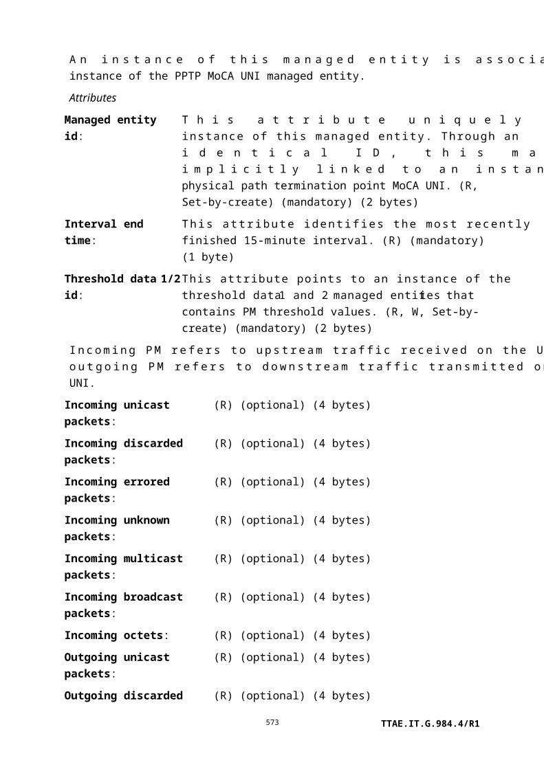
I.2.5 Plug-and-play circuit pack provisioning
A cardholder can be provisioned for a plug-and-play mode of operation (see Figure I.2.5-1). Figure I.2.5-1 shows the scenario for provisioning a slot for plug-and-play.
OLT ONU
The OLT provisions a cardholder to plug-and-play
Set_cmd[Cardholder](inst, expected Plug-in = plug&play) Set_cmd[Cardholder](inst, expected Plug-in = plug&play)
Set_rsp[Cardholder](inst, success) Set_rsp[Cardholder](inst, success)
The OLT updates its MIB and increments its MIB data sync
A circuit pack is inserted into the ONT
The ONT updates expected plugin type attr, The ONT increments the MIB data sync
AVC[Cardholder](actual plugin type=X) AVC[Cardholder](actual plugin type=X)
The OLT updates its MIB.
The OLT creates a circuit pack of the type just inserted
Create_cmd[Circuit Pack](inst, type=X) Create_cmd[Circuit Pack](inst, type=X)
Create_rsp[Circuit Pack](inst, success) Create_rsp[Circuit Pack](inst, success)
The OLT updates its MIB and increments its MIB data sync.
The ONT automatically creates:•One instance of Circuit Pack with default attributes•Two instances of Software Image•N instances of the PPTP, UNI, and TC adaptor, where N is the number of ports•M instances of downstream priority queuesThe ONT increments the MIB data sync
Figure I.2.5-1 – Plug-and-play circuit pack provisioning
Not shown in Figure I.2.5-1 are the notifications of the ONT due to incorrectly inserted circuit packs.
TTAE.IT.G.984.4/R1573

I.2.6 Plug-and-play circuit pack de-provisioning
When a circuit pack is removed from a cardholder, a notification is sent to the OLT. The OLT de-provisions the cardholder upon receiving the notification (see Figure I.2.6-1).
OLT ONU
The OLTdeletes a linecard
Delete_cmd[Circuit Pack](inst) Delete_cmd[Circuit Pack](inst)
Delete_rsp[Circuit Pack](inst, success) Delete_rsp[Circuit Pack](inst, success)
The OLT updates its MIB and increments its MIB data sync
The ONT automatically deletes associated instances of :•Circuit Pack •Software Image•PPTP, UNI, and TC adaptor•Downstream priority queuesThe ONT increments the MIB data sync
Figure I.2.6-1 – Plug-and-play circuit pack de-provisioning
I.2.7 Software image download
The software image download operation is a file transfer from the OLT to the ONT. Software download is first described in the context of the baseline OMCI message set; the description is then modified as appropriate for the extended message set.
I.2.7.1 Baseline message set download
The atomic unit of file transfer is the section, the 31 bytes of data that can be transferred in a single (baseline) download section message. The last section in a software download may be padded with null bytes as needed.
A number of sections comprise a so-called window. The size of a window may not exceed 256 sections. During the initial software download message exchange, the OLT proposes a maximum window size, but a lower value can be stipulated by the ONT, which must be accepted by the OLT. The OLT may send windows with fewer sections than this negotiated maximum, but may not exceed the maximum. Though it is not a preferred choice, the OLT may send all windows at the full negotiated maximum size, with the final window of the
TTAE.IT.G.984.4/R1574

download operation padded out with download section messages containing only null pad bytes.
Each download section message contains a sequence number, which begins anew at 0 with each window. By tracking the incrementing sequence numbers, the ONT can confirm that it has in fact received each section of code.
In the message type field of the last download section message of the window, the OLT indicates the end of the window by setting the AR (acknowledgement request) bit – prior download section messages are unacknowledged. If the ONT has not received the entire window correctly, i.e., if it misses a sequence number or discards a download section because of a CRC error, it acknowledges with a command processing error result, whereupon the OLT falls back to the beginning of the window and tries again. To improve the chance of successful transmission, the OLT may choose to reduce the size of the window on its next attempt.
When the final window has been successfully downloaded, the OLT sends an end software download message whose contents include the size of the downloaded image in bytes, along with a CRC-32 computed according to [ITU-T I.363.5], across the entire image but excluding pad bytes that may have been transmitted. If the ONT agrees with both of these values, it acknowledges successful completion of the download and updates the software image validity attribute to indicate that the newly downloaded image is valid.
The ONT should not positively acknowledge an end download message until it has confirmed image size and CRC, and performed whatever operations may be necessary – such as non-volatile storage – to accept an immediate activate or commit message from the OLT. The ONT should respond with a device busy result code until these operations are complete, and the OLT should periodically re-try the end download command.
The nested state machines in OLT and ONT can conceivably get out of step in a number of unspecified ways. Furthermore, it is not specified how to escape from a loop of transmission failure and retry. As a recovery mechanism from detectable state errors, it is recommended that the ONT reply with command processing error result codes to both acknowledged download section and end software download commands, and that the OLT send a final end software download command with a known bad CRC and image size (e.g., all 0s), whereupon both OLT and ONT should reset to the state in which no download is in progress, that is, state S1/S1' of Figure 9.1.4-1. Likewise, the OLT should be able to abort the download operation at any time by sending an end software download message with invalid CRC and image size.
As well as the download of an image to the ONT as a whole, the download messages allow an option to download an image to each of several circuit packs in parallel. The starting assumption is that the OLT knows the set of circuit packs that require the same download file, so that it can specify this set in the download command sequence.
TTAE.IT.G.984.4/R1575

Figure I.2.7-1 Software download
TTAE.IT.G.984.4/R1576

I.2.7.2 Extended message set download
When the extended message set is used for software download, the maximum size of the section is limited by the extended message format itself, and is potentially as large as 1965 bytes. The OLT may send smaller sections at will, including the final section of a file transfer. Because the extended message format allows for variable length, software image sections are never padded in this message format.
TTAE.IT.G.984.4/R1577

I.2.8 Software image activate and commit
See Figure I.2.8-1.
Figure I.2.8-1 – Software activate and software commit
Appendix II
OMCI message set
TTAE.IT.G.984.4/R1578

(This appendix does not form an integral part of this Recommendation)
II.1 General remarks
II.1.1 Message type identifier
The message types are given in clause 11.1.4.
II.1.2 Entity class identifier
The entity class identifiers are given in clause 11.1.6.
II.1.3 Result and reason
Responses to commands can indicate the result of the command. A zero value indicates that the command was processed successfully. Non-zero values indicate the reason of the failure. If the result was failure, the rest of the message contents may provide details of the failure, be filled with all 0s, or in the extended message set, simply be omitted. The definition of each result and reason appears in Table II.1.3-1:
Table II.1.3-1 – Result and reason codes
Code Headline Description
0000 Command processed successfully There are two functions for command processing: command
interpretation and command execution. This result means that
the received command, such as get/set/test/reboot, was
properly interpreted by the ONT's command interpretation
function without errors and that the interpreted command was
successfully transferred to the ONT's command execution
function.
0001 Command processing error This result means the command processing failed at the ONT
for some reason not described by one of the more specific
error codes.
0010 Command not supported This result means that the message type (baseline message set
byte 8, extended byte 3) is not supported by the ONT.
0011 Parameter error This result means that the command message received by the
ONT was errored. It would be appropriate if an attribute mask
were out of range, for example. In practice, this result code is
frequently used interchangeably with code 1001. However, the
optional-attribute and attribute execution masks in the reply
messages are only defined for code 1001.
0100 Unknown managed entity This result means that the managed entity class (baseline bytes
10..11, extended bytes 5..6) is not supported by the ONT.
TTAE.IT.G.984.4/R1579

Table II.1.3-1 – Result and reason codes
Code Headline Description
0101 Unknown managed entity
instance
This result means that the managed entity instance (baseline
bytes 12..13, extended bytes 7..8) does not exist in the ONT.
0110 Device busy This result means that the command could not be processed
due to process-related congestion at the ONT. This result code
may also be used as a pause indication to the OLT while the
ONT conducts a time-consuming operation such as storage of
a software image into non-volatile memory.
0111 Instance exists This result means that the ONT already has a managed entity
instance that corresponds to the one the OLT is attempting to
create.
TTAE.IT.G.984.4/R1580

Table II.1.3-1 – Result and reason codes
Code Headline Description
1001 Attribute(s) failed or unknown This result means that an optional attribute is not supported by
the ONT or that a mandatory/optional attribute could not be
executed by the ONT, even if it is supported, for example,
because of a range or type violation. In conjunction with this
result, attribute masks are used to indicate which attributes
failed or were unknown.
The following two kinds of attribute masks are used when this
result/reason is raised:
• optional attribute mask coding, which indicates
whether or not the optional attribute is supported;
• attribute execution mask coding, which indicates
whether or not the mandatory/optional attribute was
executed.
See the set response and get response message layouts
(clauses II.2.10, II.2.12, II.3.10 and II.3.12) for the placement
of these masks.
If one or more optional attributes are not supported by the
ONT, the optional attribute mask coding for each unsupported
optional attribute becomes 1, while the corresponding attribute
execution mask coding remains 0.
If one or more mandatory or optional attributes were not
executed by the ONT, the optional attribute mask coding
remains 0, while the attribute execution mask coding becomes
1 for each failed attribute.
If the ONT could not latch copies of all specified table
attributes, for example, because of insufficient memory, the
attribute execution mask is set to 1 for each attribute that does
not have a latched copy available for get next retrieval.
II.1.4 Get, get response, create response, and set messages
For an attribute mask, a bit map is used in the get, get response, create response, and set messages. This bit map indicates which attributes are requested (get) or provided (get response and set). The bit map is composed as follows:
TTAE.IT.G.984.4/R1581

ByteBit
8 7 6 5 4 3 2 1
1 Attribute 1 Attribute 2 Attribute 3 Attribute 4 Attribute 5 Attribute 6 Attribute 7 Attribute 8
2 Attribute 9 Attribute 10 Attribute 11 Attribute 12 Attribute 13 Attribute 14 Attribute 15 Attribute 16
Attribute numbers correspond to the ordering of the attributes in clause 9. Note that the managed entity identifier, which is an attribute of each managed entity, has no corresponding bit in the attribute mask. Thus, attributes are counted starting from the first attribute after the managed entity identifier.
II.1.5 Alarm notifications
The ONT sends this notification each time an alarm status changes for the entity indicated in the message identifier. The message shows the status of all alarms of this entity. It is up to the OLT to determine which alarm status has changed.
The maximum number of alarms supported by OMCI for a given managed entity instance is 224 because of the available message field of the baseline get all alarm next message. The bit map is composed as follows:
ByteBit
8 7 6 5 4 3 2 1
1 Alarm 0 Alarm 1 Alarm 2 Alarm 3 Alarm 4 Alarm 5 Alarm 6 Alarm 7
2 Alarm 8 Alarm 9 Alarm 10 Alarm 11 Alarm 12 Alarm 13 Alarm 14 Alarm 15
…
28 Alarm 216 Alarm 217 Alarm 218 Alarm 219 Alarm 220 Alarm 221 Alarm 222 Alarm 223
Alarm numbers correspond to the alarm coding in clause 9. Bits in the alarm bit map that correspond to non-existing alarms are always set to 0. Bits that correspond to defined alarms are set to 0 to indicate that the corresponding alarm is cleared, or to 1 to indicate that the alarm is currently active.
Alarm message sequence numbers can take values in the interval 1 to 255. Zero is excluded in order to make this counter similar to the MIB data sync counter.
II.1.6 Test, test response and test result
The descriptions below indicate how test, test response and test result messages are related.
Test: This message is used to initiate either a self test or any of the other specific tests defined against various managed entity types.
TTAE.IT.G.984.4/R1582

Test response: This message is an immediate reaction to a test message. The test response message reports the ability of the ONT to run the required test, but it does not contain any specific results.
Test result: This message is used to report the result of either a self test (requested by the OLT) or one of the specific tests defined against various managed entity types. The test result notification is not used for autonomous tests that produce only pass-fail results. Instead, notification is sent to the OLT via an alarm if the managed entity fails its autonomous self test. Autonomous tests on the ANI-G managed entity may, however, be reported with an autonomous test result message, with or without corresponding alarms, on grounds that the actual measured values may be important.
A test on a particular managed entity instance is invoked by sending a test message to this instance. Each managed entity that supports tests needs to have an action test defined for it. The type of test invoked by a test message depends on the managed entity.
The test response message is an indication to the OLT that the test request is received and is being processed. The results of a requested test are sent to the OLT via a specific test result message.
The test response message is sent immediately after the test message is received (i.e., within the normal response time). The transaction identifier of the test response message is identical to the transaction identifier of the test message that requested the test.
II.2 Baseline OMCI message layout
II.2.1 Create
Field Byte 8 7 6 5 4 3 2 1 Comments
Transaction
identifier
6-7
Message type 8 0 1 0 DB = 0, AR = 1, AK = 0
bits 5-1: action = create
Device identifier
type
9 0 0 0 0 1 0 1 0 OMCI = 0x0A
Message entity
identifier
10-11 Entity class
12 MS byte entity instance
13 LS byte entity instance
TTAE.IT.G.984.4/R1583

Field Byte 8 7 6 5 4 3 2 1 Comments
Message contents 14 Attribute value of first set-by-create
attribute, NOT the ME ID (size
depending on the type of attribute)
…
Attribute value of last set-by-create
attribute (size depending on the
type of attribute)
xx-45 0 0 0 0 0 0 0 0 Padding
It should be noted that the message contents for the "create" message apply only to attributes that are defined to be "set-by-create". Writeable attributes that are not set-by-create are not permitted in a create message. Thus, the first byte of the message contents field begins with the attribute value for the first set-by-create attribute and so forth. Space for each set-by-create attribute must be allocated in the create message, even if the attribute is optional. When an optional attribute is not to be instantiated, the placeholder value to be entered into this space is specific to the definition of each attribute.
II.2.2 Create response
Field Byte 8 7 6 5 4 3 2 1 Comments
Transaction
identifier
6-7
Message type 8 0 0 1 DB = 0, AR = 0, AK = 1
bits 5-1: action = create
Device identifier
type
9 0 0 0 0 1 0 1 0 OMCI = 0x0A
Message entity
identifier
10-11 Entity class
12 MS byte entity instance
13 LS byte entity instance
Message contents 14 0 0 0 0 x x x x Result, reason
0000 = command processed
successfully
0001 = command processing error
0010 = command not supported
0011 = parameter error
0100 = unknown managed entity
0101 = unknown managed entity
TTAE.IT.G.984.4/R1584

Field Byte 8 7 6 5 4 3 2 1 Comments
instance
0110 = device busy
0111 = instance exists
15 Attribute execution mask
(attributes 1-8), used with 0011
encoding:
0 = attribute ok
1 = illegal value attribute
16 Attribute execution mask
(attributes 9-16), used with 0011
encoding:
0 = attribute ok
1 = illegal value attribute
17-45 0 0 0 0 0 0 0 0 Padding
II.2.3 This clause intentionally left blank
II.2.4 This clause intentionally left blank
II.2.5 Delete
Field Byte 8 7 6 5 4 3 2 1 Comments
Transaction
identifier
6-7
Message type 8 0 1 0 DB = 0, AR = 1, AK = 0
bits 5-1: action = delete
Device identifier
type
9 0 0 0 0 1 0 1 0 OMCI = 0x0A
Message entity
identifier
10-11 Entity class
12 MS byte entity instance
13 LS byte entity instance
Message contents 14-45 0 0 0 0 0 0 0 0 Padding
TTAE.IT.G.984.4/R1585

II.2.6 Delete response
Field Byte 8 7 6 5 4 3 2 1 Comments
Transaction
identifier
6-7
Message type 8 0 0 1 DB = 0, AR = 0, AK = 1
bits 5-1: action = delete
Device identifier
type
9 0 0 0 0 1 0 1 0 OMCI = 0x0A
Message entity
identifier
10-11 Entity class
12 MS byte entity instance
13 LS byte entity instance
Message contents 14 Result, reason
0000 = command processed
successfully
0001 = command processing
error
0010 = command not supported
0011 = parameter error
0100 = unknown managed
entity
0101 = unknown managed
entity
instance
0110 = device busy
15-45 0 0 0 0 0 0 0 0 Padding
II.2.7 This clause intentionally left blank
II.2.8 This clause intentionally left blank
II.2.9 Set
Field Byte 8 7 6 5 4 3 2 1 Comments
Transaction
identifier
6-7
TTAE.IT.G.984.4/R1586

Field Byte 8 7 6 5 4 3 2 1 Comments
Message type 8 0 1 0 DB = 0, AR = 1, AK = 0
bits 5-1: action = set
Device identifier
type
9 0 0 0 0 1 0 1 0 OMCI = 0x0A
Message entity
identifier
10-11 Entity class
12 MS byte entity instance
13 LS byte entity instance
Message contents 14 MS byte attribute mask
15 LS byte attribute mask
16 Attribute value of first attribute to
set (size depending on the type of
attribute)
…
Attribute value of last attribute to
set (size depending on the type of
attribute)
xx-45 0 0 0 0 0 0 0 0 Padding
II.2.10 Set response
Field Byte 8 7 6 5 4 3 2 1 Comments
Transaction
identifier
6-7
Message type 8 0 0 1 DB = 0, AR = 0, AK = 1
bits 5-1: action = set
Device identifier
type
9 0 0 0 0 1 0 1 0 OMCI = 0x0A
Message entity
identifier
10-11 Entity class
12 MS byte entity instance
13 LS byte entity instance
TTAE.IT.G.984.4/R1587

Field Byte 8 7 6 5 4 3 2 1 Comments
Message contents 14 0 0 0 0 x x x x Result, reason
0000 = command processed
successfully
0001 = command processing error
0010 = command not supported
0011 = parameter error
0100 = unknown managed entity
0101 = unknown managed entity
instance
0110 = device busy
1001 = attribute(s) failed or
unknown
15 Optional attribute mask (attributes
1-8), used with 1001 encoding:
0 = default
1 = unsupported attribute
16 Optional attribute mask (attributes
9-16), used with 1001 encoding:
0 = default
1 = unsupported attribute
17 Attribute execution mask (attributes
1-8), used with 1001 encoding:
0 = default
1 = failed attribute
18 Attribute execution mask (attributes
9-16), used with 1001 encoding:
0 = default
1 = failed attribute
19-45 0 0 0 0 0 0 0 0 Padding
II.2.11 Get
Field Byte 8 7 6 5 4 3 2 1 Comments
Transaction
identifier
6-7
TTAE.IT.G.984.4/R1588

Field Byte 8 7 6 5 4 3 2 1 Comments
Message type 8 0 1 0 DB = 0, AR = 1, AK = 0
bits 5-1: action = get
Device identifier
type
9 0 0 0 0 1 0 1 0 OMCI = 0x0A
Message entity
identifier
10-11 Entity class
12 MS byte entity instance
13 LS byte entity instance
Message contents 14 MS byte attribute mask
15 LS byte attribute mask
16-45 0 0 0 0 0 0 0 0 Padding
Based on the size of the message contents field, the aggregate size of the attributes requested by a single get command should not exceed 25 bytes.
II.2.12 Get response
Field Byte 8 7 6 5 4 3 2 1 Comments
Transaction
identifier
6-7
Message type 8 0 0 1 DB = 0, AR = 0, AK = 1
bits 5-1: action = get
Device identifier
type
9 0 0 0 0 1 0 1 0 OMCI = 0x0A
Message entity
identifier
10-11 Entity class
12 MS byte entity instance
13 LS byte entity instance
TTAE.IT.G.984.4/R1589
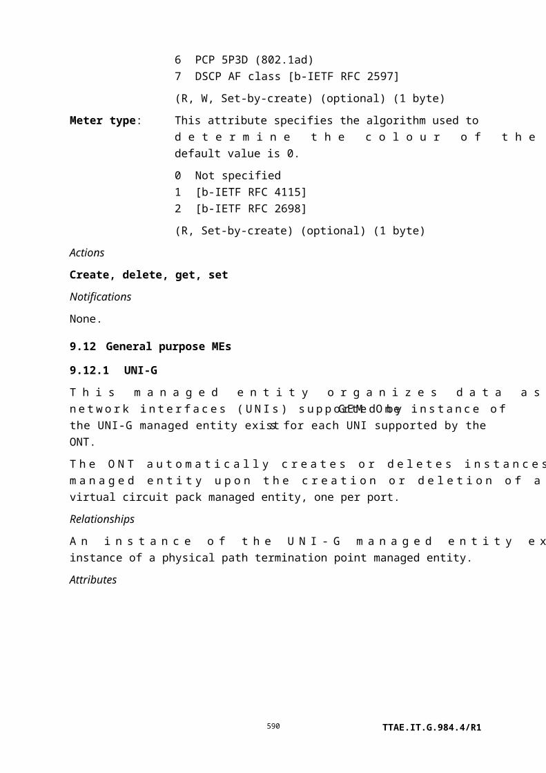
Field Byte 8 7 6 5 4 3 2 1 Comments
Message contents 14 0 0 0 0 x x x x Result, reason
0000 = command processed
successfully
0001 = command processing
error
0010 = command not supported
0011 = parameter error
0100 = unknown managed
entity
0101 = unknown managed
entity
instance
0110 = device busy
1001 = attribute(s) failed or
unknown
15 MS byte attribute mask
16 LS byte attribute mask
17 Attribute value of first attribute
included (size depending on the
type of attribute)
…
Attribute value of last attribute
included (size depending on the
type of attribute)
xx-41 0 0 0 0 0 0 0 0 Padding
42 Optional attribute mask
(attributes 1-8), used with 1001
encoding:
0 = default
1 = unsupported attribute
TTAE.IT.G.984.4/R1590

Field Byte 8 7 6 5 4 3 2 1 Comments
43 Optional attribute mask
(attributes 9-16), used with 1001
encoding:
0 = default
1 = unsupported attribute
44 Attribute execution mask
(attributes 1-8), used with 1001
encoding:
0 = default
1 = failed attribute
45 Attribute execution mask
(attributes 9-16), used with 1001
encoding:
0 = default
1 = failed attribute
Bytes 42 to 45 are always reserved for the optional attribute and attribute execution masks; however, the content of these bytes is only valid in conjunction with the 1001 encoding used to indicate failed or unknown attributes.
When the ONT wishes to transfer an attribute whose size is or might be larger than the space available in one OMCI message, the ONT responds with four bytes to indicate the size of that attribute with an appropriate attribute mask. The OLT should then use the get next message in order to retrieve the attribute.
II.2.13 This clause intentionally left blank
II.2.14 This clause intentionally left blank
II.2.15 Get all alarms
Field Byte 8 7 6 5 4 3 2 1 Comments
Transaction
identifier
6-7
Message type 8 0 1 0 DB = 0, AR = 1, AK = 0
bits 5-1: action = get all alarms
Device identifier
type
9 0 0 0 0 1 0 1 0 OMCI = 0x0A
TTAE.IT.G.984.4/R1591

Message entity
identifier
10-11 Entity class = ONT data
12 0 0 0 0 0 0 0 0 MS byte entity instance
13 0 0 0 0 0 0 0 0 LS byte entity instance
Message contents 14 0 0 0 0 0 0 0 x x = alarm retrieval mode
0 = Get all alarms
regardless of
ARC status
1 = Get all alarms not
currently
under ARC
15-45 0 0 0 0 0 0 0 0 Padding
II.2.16 Get all alarms response
Field Byte 8 7 6 5 4 3 2 1 Comments
Transaction
identifier
6-7
Message type 8 0 0 1 DB = 0, AR = 0, AK = 1
bits 5-1: action = get all alarms
Device identifier
type
9 0 0 0 0 1 0 1 0 OMCI = 0x0A
Message entity
identifier
10-11 Entity class = ONT data
12 0 0 0 0 0 0 0 0 MS byte entity instance
13 0 0 0 0 0 0 0 0 LS byte entity instance
Message contents 14 MS byte of the number of
subsequent commands
15 LS byte of the number of
subsequent commands
16-45 0 0 0 0 0 0 0 0 Padding
II.2.17 Get all alarms next
Field Byte 8 7 6 5 4 3 2 1 Comments
Transaction
identifier
6-7
Message type 8 0 1 0 DB = 0, AR = 1, AK = 0
bits 5-1: action = get all alarms
TTAE.IT.G.984.4/R1592

Field Byte 8 7 6 5 4 3 2 1 Comments
next
Device identifier
type
9 0 0 0 0 1 0 1 0 OMCI = 0x0A
Message entity
identifier
10-11 Entity class = ONT data
12 0 0 0 0 0 0 0 0 MS byte entity instance
13 0 0 0 0 0 0 0 0 LS byte entity instance
Message contents 14 MS byte of the command
sequence number
15 LS byte of the command
sequence number
16-45 0 0 0 0 0 0 0 0 Padding
The command sequence numbers shall start from 0x00 onwards.
II.2.18 Get all alarms next response
Field Byte 8 7 6 5 4 3 2 1 Comments
Transaction
identifier
6-7
Message type 8 0 0 1 DB = 0, AR = 0, AK = 1
bits 5-1: action = get all alarms
next
Device identifier
type
9 0 0 0 0 1 0 1 0 OMCI = 0x0A
Message entity
identifier
10-11 Entity class = ONT data
12 0 0 0 0 0 0 0 0 MS byte entity instance
13 0 0 0 0 0 0 0 0 LS byte entity instance
Message contents 14-15 Entity class on which the alarms
are reported
16 MS byte entity instance on which
the alarms are reported
17 LS byte entity instance on which
the alarms are reported
18-45 x x x x x x x x Bit map alarms
The bit map used in the get all alarms next response for a given managed entity class is identical to the bit map used in the alarm notifications for that managed entity class.
TTAE.IT.G.984.4/R1593

In the case where the ONT receives a get all alarms next request message in which the command sequence number is out of range, the ONT should respond with a message in which bytes 14 to 45 are all set to 0. This corresponds to a response with entity class 0, entity instance 0, and bit map all 0s.
II.2.19 MIB upload
Field Byte 8 7 6 5 4 3 2 1 Comments
Transaction
identifier
6-7
Message type 8 0 1 0 DB = 0, AR = 1, AK = 0
bits 5-1: action = MIB upload
Device identifier
type
9 0 0 0 0 1 0 1 0 OMCI = 0x0A
Message entity
identifier
10-11 Entity class = ONT data
12 0 0 0 0 0 0 0 0 MS byte entity instance
13 0 0 0 0 0 0 0 0 LS byte entity instance
Message contents 14-45 0 0 0 0 0 0 0 0 Padding
II.2.20 MIB upload response
Field Byte 8 7 6 5 4 3 2 1 Comments
Transaction
identifier
6-7
Message type 8 0 0 1 DB = 0, AR = 0, AK = 1
bits 5-1: action = MIB upload
Device identifier
type
9 0 0 0 0 1 0 1 0 OMCI = 0x0A
Message entity
identifier
10-11 Entity class = ONT data
12 0 0 0 0 0 0 0 0 MS byte entity instance
13 0 0 0 0 0 0 0 0 LS byte entity instance
Message contents 14 MS byte of the number of
subsequent commands
15 LS byte of the number of
subsequent commands
16-45 0 0 0 0 0 0 0 0 Padding
TTAE.IT.G.984.4/R1594
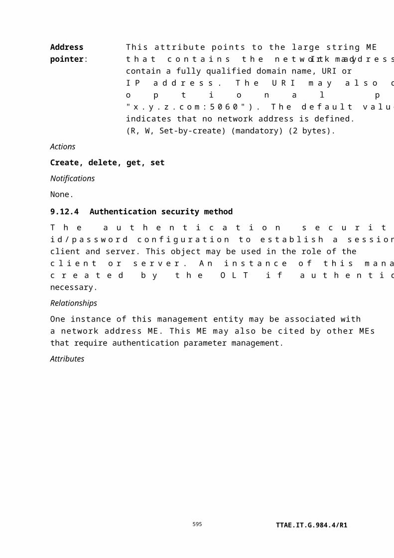
II.2.21 MIB upload next
Field Byte 8 7 6 5 4 3 2 1 Comments
Transaction
identifier
6-7
Message type 8 0 1 0 DB = 0, AR = 1, AK = 0
bits 5-1: action = MIB upload next
Device identifier
type
9 0 0 0 0 1 0 1 0 OMCI = 0x0A
Message entity
identifier
10-11 Entity class = ONT data
12 0 0 0 0 0 0 0 0 MS byte entity instance
13 0 0 0 0 0 0 0 0 LS byte entity instance
Message contents 14 MS byte of the command sequence
number
15 LS byte of the command sequence
number
16-45 0 0 0 0 0 0 0 0 Padding
The command sequence numbers shall start from 0 onwards.
II.2.22 MIB upload next response
Field Byte 8 7 6 5 4 3 2 1 Comments
Transaction
identifier
6-7
Message type 8 0 0 1 DB = 0, AR = 0, AK = 1
bits 5-1: action = MIB upload
next
Device identifier
type
9 0 0 0 0 1 0 1 0 OMCI = 0x0A
Message entity
identifier
10-11 Entity class = ONT data
12 0 0 0 0 0 0 0 0 MS byte entity instance
13 0 0 0 0 0 0 0 0 LS byte entity instance
TTAE.IT.G.984.4/R1595

Field Byte 8 7 6 5 4 3 2 1 Comments
Message contents 14-15 Entity class of object
16 MS byte entity instance of object
17 LS byte entity instance of object
18 MS byte attribute mask
19 LS byte attribute mask
20 Value of first attribute (size
depending on the type of the
attribute)
...
Value of the last attribute (size
depending on the type of the
attribute)
xx-45 0 0 0 0 0 0 0 0 Padding
If the ONT receives a MIB upload next request message in which the command sequence number is out of range, it should respond with a message in which bytes 14 to 45 are all set to 0. This corresponds to a response with entity class 0x0000, entity instance 0x0000, attribute mask 0x0000, and padding from byte 20 to byte 45.
Note that, if all attributes of a managed entity do not fit within one MIB upload next response message, the attributes will be split over several messages. The OLT can use the information in the attribute mask to determine which attribute values are reported in which MIB upload next response message.
II.2.23 MIB reset
Field Byte 8 7 6 5 4 3 2 1 Comments
Transaction
identifier
6-7
Message type 8 0 1 0 DB = 0, AR = 1, AK = 0
bits 5-1: action = MIB reset
Device identifier
type
9 0 0 0 0 1 0 1 0 OMCI = 0x0A
Message entity
identifier
10-11 Entity class = ONT data
12 0 0 0 0 0 0 0 0 MS byte entity instance
13 0 0 0 0 0 0 0 0 LS byte entity instance
Message contents 14-45 0 0 0 0 0 0 0 0 CRC-32, computed over all bytes
of the software image (excluding
TTAE.IT.G.984.4/R1596

Field Byte 8 7 6 5 4 3 2 1 Comments
padding), as specified in
[ITU-T I.363.5].
II.2.24 MIB reset response
Field Byte 8 7 6 5 4 3 2 1 Comments
Transaction
identifier
6-7
Message type 8 0 0 1 DB = 0, AR = 0, AK = 1
bits 5-1: action = MIB reset
Device identifier
type
9 0 0 0 0 1 0 1 0 OMCI = 0x0A
Message entity
identifier
10-11 Entity class = ONT data
12 0 0 0 0 0 0 0 0 MS byte entity instance
13 0 0 0 0 0 0 0 0 LS byte entity instance
Message contents 14 0 0 0 0 x x x x Result, reason
0000 = command processed
successfully
0001 = command processing error
0010 = command not supported
0011 = parameter error
0100 = unknown managed entity
0101 = unknown managed entity
instance
0110 = device busy
15-45 0 0 0 0 0 0 0 0 Padding
TTAE.IT.G.984.4/R1597

II.2.25 Alarm
Field Byte 8 7 6 5 4 3 2 1 Comments
Transaction
identifier
6-7
Message type 8 0 0 0 DB = 0, AR = 0, AK = 0
bits 5-1: action = alarm
Device identifier
type
9 0 0 0 0 1 0 1 0 OMCI = 0x0A
Message entity
identifier
10-11 Entity class
12 MS byte entity instance
13 LS byte entity instance
Message contents 14 Alarm mask
…
41 Alarm mask
42-44 0 0 0 0 0 0 0 0 Padding
45 Alarm sequence number
II.2.26 Attribute value change
Field Byte 8 7 6 5 4 3 2 1 Comments
Transaction
identifier
6-7
Message type 8 0 0 0 DB = 0, AR = 0, AK = 0
bits 5-1: action = attribute value
change
Device identifier
type
9 0 0 0 0 1 0 1 0 OMCI = 0x0A
Message entity
identifier
10-11 Entity class
12 MS byte entity instance
13 LS byte entity instance
TTAE.IT.G.984.4/R1598

Field Byte 8 7 6 5 4 3 2 1 Comments
Message contents 14 MS byte attribute mask
15 LS byte attribute mask
16 Attribute value of first attribute
changed (size depending on the
type of attribute)
...
Attribute value of last attribute
changed (size depending on the
type of attribute)
xx-45 0 0 0 0 0 0 0 0 Padding
NOTE – For table attributes, the AVC message will contain no attribute value (only a mask), and no
snapshot of the table will be created. If the OLT wishes to obtain the new value, it will then do a get
operation, followed by the required number of get next operations.
NOTE 1 – For table attributes, the AVC message contains no attribute value (only a mask), and no
snapshot of the table is created. If the OLT wishes to obtain the new value, it must then do a get
operation, followed by the required number of get next operations.
NOTE 2 – If there is insufficient space in the message body for the new values of all changed (non-
table) attributes, the ONT should issue multiple AVCs, each with a consistent attribute mask and list
of new attribute values, the total to include all changed attributes and their new values.
II.2.27 Test
The format of the test message is specific to the target entity class. A number of formats are presently defined. Future test extensions for a given entity class can be supported by adding additional encodings to presently unused bits or bytes. Future specification of tests for other entity classes may use an existing format or may define new formats for the test message. These extension mechanisms allow future tests to be supported without changing the principle of operation.
Format for dot1ag MEP entity class, loopback test
Field Byte 8 7 6 5 4 3 2 1 Comments
Transaction identifier 6-7
Message type 8 0 1 0 DB = 0, AR = 1, AK = 0
bits 5-1: action = test
Device identifier type 9 0 0 0 0 1 0 1 0 OMCI = 0x0A
TTAE.IT.G.984.4/R1599

Field Byte 8 7 6 5 4 3 2 1 Comments
Managed entity
identifier
10-11 Entity class.
NOTE – This format applies to
the dot1ag MEP entity class.
12 MSB entity instance
13 LSB entity instance
Message contents 14 0 0 0 0 0 0 0 x x=select test
0: Ethernet loopback test
1: IEEE 802.1ag link trace test
(see separate format description
below)
Other values reserved
15 0 0 0 c p p p d If c = 1, the value of the MEP's
CCM and LTM priority
attribute is used, with drop
eligibility false.
If c = 0, pppd represents the
priority (p bits) and drop
eligibility fields of the
transmitted LBM frame.
16-21 MAC address of target MHF or
MEP, or 0 if the destination
MEP ID is to be used instead.
[b-IEEE 802.1ag] specifies
unicast addresses; [b-
ITU-T Y.1731] also allows for
multicast.
22-23 Destination MEP ID, in the
range 1..8191, or 0 if the MAC
address in bytes 16-21 is to be
used instead.
TTAE.IT.G.984.4/R1600

Field Byte 8 7 6 5 4 3 2 1 Comments
24-25 Repetition count, range 1..1024.
This governs how many LBMs
are generated. The rate at which
LBMs are generated is not
specified. If 5 seconds elapses
with no LBRs received, the test
aborts.
26-27 These four fields are pointers to
as many as four-octet string
MEs, which are concatenated to
form an octet string of up to
1500 bytes. The string is
packaged into a data TLV and
transmitted as part of the LBM.
If all four fields are null
pointers, no data TLV is sent. If
only one octet string is needed,
it should be specified in bytes
23..24, etc., with null pointers in
the higher-numbered bytes of
the test message.
28-29
30-31
32-33
34-45 0 0 0 0 0 0 0 0 Padding
Format for dot1ag MEP entity class, linktrace test
Field Byte 8 7 6 5 4 3 2 1 Comments
Transaction identifier 6-7
Message type 8 0 1 0 DB = 0, AR = 1, AK = 0
bits 5-1: action = test
Device identifier type 9 0 0 0 0 1 0 1 0 OMCI = 0x0A
Managed entity
identifier
10-11 Entity class. NOTE – This format
applies to the dot1ag MEP entity
class.
12 MSB entity instance
13 LSB entity instance
Message contents 14 0 0 0 0 0 0 0 x x=select test
TTAE.IT.G.984.4/R1601

Field Byte 8 7 6 5 4 3 2 1 Comments
0: Ethernet loopback test (see
separate format description above)
1: IEEE 802.1ag link trace test
Other values reserved
15 f 0 0 0 0 0 0 0 Flags, a bit mask
f: Use FDB only. When 1, the bridge
uses only its normal MAC
forwarding tables for forwarding.
When 0, the bridge may also consult
its MIP CCM database to determine
the forwarding port.
16-21 Unicast MAC address of target MHF
or MEP, or 0 if the destination MEP
ID is to be used instead.
22-23 Destination MEP ID, in the range
1..8191, or 0 if the unicast MAC
address in bytes 16-21 is to be used
instead.
24 Max hops count – specifies initial
TTL (time to live); limits the number
of relay stages through which the
LTM is forwarded before being
discarded, and the number of LTRs
that may be returned.
[b-IEEE 802.1ag] recommends a
default value of 64.
25-26 Pointer to a general purpose buffer
ME, used to return the link trace
results. The ONT should deny the
test operation command if this field
is a null or an invalid pointer.
27-45 0 0 0 0 0 0 0 0 Padding
Format for POTS UNI and PPTP ISDN UNI entity classes
This message supports two basic categories of test operation, a defined set of tests that look in and out from the POTS port, and a set of codepoints that may be used for vendor-specific tests. The latter category is further subdivided into codepoints that return test results in a
TTAE.IT.G.984.4/R1602

general purpose buffer ME, using the test results message primarily as an event trigger to signal test completion, and codepoints that return all test results in an ordinary test result message. If it is needed, the OLT must create the general purpose buffer managed entity before initiating the test action.
Note that a single message can be used to initiate multiple tests on a given ME if desired.
Bytes 15-28 are used by the dial tone make-break test. A zero value for a timer causes the ONT to use its built-in defaults. As many as three dial tone frequencies can be specified, or omitted by setting their values to 0. Other fields are also omitted with the value 0, or controlled by flags. An ONT can support the dial tone test with internal defaults only, and is not required to support any of the attributes of bytes 15-28. Likewise, an ONT can use internal defaults for drop test, rather than the values given in bytes 29-38. The capabilities of an ONT are documented by the vendor and known through administrative practices.
Field Byte 8 7 6 5 4 3 2 1 Comments
Transaction
identifier
6-7
Message type 8 0 1 0 DB = 0, AR = 1, AK = 0
Bits 5-1: action = test
Device identifier
type
9 0 0 0 0 1 0 1 0 OMCI = 0x0A
Message identifier 10-11 Entity class.
NOTE – This format applies to
entity classes PPTP POTS UNI
and PPTP ISDN UNI.
12 MS byte entity instance
13 LS byte entity instance
TTAE.IT.G.984.4/R1603
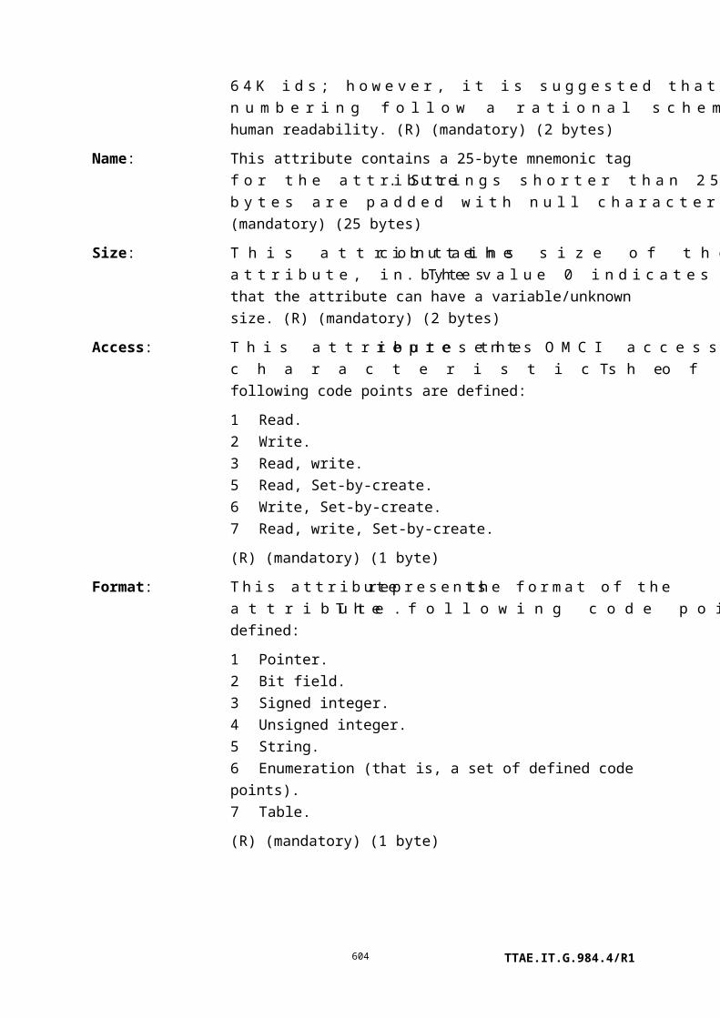
Field Byte 8 7 6 5 4 3 2 1 Comments
14 a 0 0 0 x x x x a – test mode
0 = normal; deny test if
line busy
1 = forced mode
xxxx = select test
0000 = all MLT tests
0001 = hazardous potential
0010 = foreign EMF
0011 = resistive faults
0100 = receiver off-hook
0101 = ringer
0110 = NT1 dc signature test
0111 = self test
1000 = dial tone make-break test
1001..1011 = vendor-specific
test,
all results returned in test results
message
1100..1111 is a vendor-specific
test, test results returned in
general purpose buffer ME. The
ONT should deny a test
operation command in this range
if bytes 39-40 do not point to a
GP buffer.
15 DBDT timer T1 (slow dial tone
threshold), in units of 0.1
seconds. Range 0.1 to 6.0
seconds.
16 DBDT timer T2 (no dial tone
threshold), in units of 0.1
seconds. Range 1.0 to 10.0
seconds.
17 DBDT timer T3 (slow break dial
tone threshold), in units of 0.1
seconds. Range 0.1 to 3.0
seconds.
TTAE.IT.G.984.4/R1604

Field Byte 8 7 6 5 4 3 2 1 Comments
18 DBDT timer T4 (no break dial
tone threshold), in units of 0.1
seconds. Range 1.0 to 3.0
seconds.
19 d p DBDT control byte
d: dialled digit
1 = dialled digit
specified in
byte 2
0
0 = use default
digit
p = pulse (1) or tone (0) dialling
20 Digit to be dialled, ASCII
character in range "0"-"9", "*",
"#".
21-22 Dial tone frequency 1, in units of
Hz
23-24 Dial tone frequency 2, in units of
Hz. 0 = unused (i.e., if only one
tone is specified).
25-26 Dial tone frequency 3, in units of
Hz. 0 = unused (i.e., if only one
or two tones are specified).
27 Dial tone power threshold,
absolute value, 0.1 dB resolution,
range [–]0.1 to [–]25.3 dBm0,
e.g., –13 dBm0 = 0x82. 0x00 =
unspecified.
28 Idle channel power threshold,
absolute value, 1 dB resolution,
range [–]1 to [–]90 dBm0. 0x00
= unspecified.
29 DC hazardous voltage threshold,
absolute value, volts 0x00 =
unspecified.
30 AC hazardous voltage threshold,
volts RMS 0x00 = unspecified
TTAE.IT.G.984.4/R1605

Field Byte 8 7 6 5 4 3 2 1 Comments
31 DC foreign voltage threshold,
absolute value, volts 0x00 =
unspecified
32 AC foreign voltage threshold,
volts RMS 0x00 = unspecified
33 Tip-ground and ring-ground
resistance threshold, kΩ 0x00 =
unspecified
34 Tip-ring resistance threshold, kΩ
0x00 = unspecified
35-36 Ringer equivalence minimum
threshold, in 0.01 REN units
0x00 = unspecified
37-38 Ringer equivalence maximum
threshold, in 0.01 REN units
0x00 = unspecified.
39..40 Pointer to a general purpose
buffer ME, used to return
vendor-specific test results
41-45 0 0 0 0 0 0 0 0 Padding
II.2.28 Test response
If an ONT does not support all tests requested in byte 14 of the test message, it should not execute any test and should respond with result 0010, command not supported. If an ONT supports all of the requested tests but cannot support one or more of the explicitly specified threshold attributes, it should not execute any test and should respond with result 0011, parameter error. The test command could then be re-issued with different thresholds or default thresholds, and would be expected to succeed.
Field Byte 8 7 6 5 4 3 2 1 Comments
Transaction
identifier
6-7
Message type 8 0 0 1 DB = 0, AR = 0, AK = 1
bits 5-1: action = test
Device identifier
type
9 0 0 0 0 1 0 1 0 OMCI = 0x0A
Message identifier 10-11 Entity class
TTAE.IT.G.984.4/R1606

Field Byte 8 7 6 5 4 3 2 1 Comments
12 MS byte entity instance
13 LS byte entity instance
Message contents 14 0 0 0 0 x x x x Result, reason
0000 = command processed
successfully
0001 = command processing
error
0010 = command not
supported
0011 = parameter error
0100 = unknown managed
entity
0101 = unknown managed
entity
instance
0110 = device busy
15-45 0 0 0 0 0 0 0 0 Padding
The test response message is an indication to the OLT that the test request is received and is being processed.
II.2.29 Start software download
When a file is to be downloaded to a single instance of the software image managed entity, the ME id is specified in bytes 12..13. An optional feature permits the same file to be downloaded to a number of circuit packs by setting bytes 12..13 = 0xffff and specifying the software image ME ids in bytes 20..21, etc.
Field Byte 8 7 6 5 4 3 2 1 Comments
Transaction
identifier
6-7
Message type 8 0 1 0 DB = 0, AR = 1, AK = 0
bits 5-1: action = start software
download
Device identifier
type
9 0 0 0 0 1 0 1 0 OMCI = 0x0A
TTAE.IT.G.984.4/R1607

Field Byte 8 7 6 5 4 3 2 1 Comments
Message identifier 10-11 Entity class = software image
12 MS byte of software image
instance
0 = ONT-G
1..254 = slot number
255 = download to multiple
software image managed entities
13 LS byte of software image
instance
0 = instance 0
1 = instance 1
255 = multiple download
Message contents 14 Window size – 1
15-18 Image size in bytes
19 Number of circuit packs to be
updated in parallel (value 1...9)
20 MS byte of software image
instance (slot number of circuit
pack)
21 LS byte of software image
instance (value 0..1)
22-xx Software image ME ids (same
format as bytes 20..21) for
additional simultaneous
downloads
xx-45 0 0 0 0 0 0 0 0 Padding
II.2.30 Start software download response
When a file is downloaded to a single software image ME, the response contains the target ME id in bytes 12..13, a result code in byte 14, a window size counter-proposal (which may be the same as that suggested by the OLT in the original request), and 0 padding for the remaining bytes.
An ONT that supports the optional parallel download feature responds with the full format shown below. If the ONT does not support the parallel download feature, it responds with the code 0b0101, unknown managed entity instance.
TTAE.IT.G.984.4/R1608

Field Byte 8 7 6 5 4 3 2 1 Comments
Transaction
identifier
6-7
Message type 8 0 0 1 DB = 0, AR = 0, AK = 1
bits 5-1: action = start software
download
Device identifier
type
9 0 0 0 0 1 0 1 0 OMCI = 0x0A
Message identifier 10-11 Entity class = software image
12 MS byte of software image
instance
0 = ONT-G
1..254 = slot number
255 = download to multiple
software image managed entities
13 LS byte of software image
instance
0 = instance 0
1 = instance 1
255 = multiple download
Message contents 14 0 0 0 0 x x x x Result, reason
0000 = command processed
successfully
0001 = command processing
error
0010 = command not supported
0011 = parameter error
0100 = unknown managed
entity
0101 = unknown managed
entity
instance
0110 = device busy
15 Window size – 1
16 Number of instances responding
(value 0..9)
TTAE.IT.G.984.4/R1609

Field Byte 8 7 6 5 4 3 2 1 Comments
17-18 ME id of software image entity
instance (slot number plus
instance 0..1)
19 Result, reason for bytes 17..18 –
same coding as byte 14
20-xx Repeat coding of bytes 17..19 for
additional requested software
image instances
xx-45 0 0 0 0 0 0 0 0 Padding
II.2.31 Download section
Field Byte 8 7 6 5 4 3 2 1 Comments
Transaction
identifier
6-7
Message type 8 0 x 0 DB = 0, AR = x, AK = 0
x = 0: no response expected
(section within the window)
x = 1: response expected (last
section of a window)
bits 5-1: action = sw download
section
Device identifier
type
9 0 0 0 0 1 0 1 0 OMCI = 0x0A
Message identifier 10-11 Entity class = software image
12 MS byte of software image
instance
0 = ONT-G
1..254 = slot number
255 = download to multiple
software image managed entities
TTAE.IT.G.984.4/R1610

Field Byte 8 7 6 5 4 3 2 1 Comments
13 LS byte of software image
instance
0 = instance 0
1 = instance 1
255 = multiple download
Message contents 14 Download section number
15-45 Data; 0 padding if final transfer
requires only a partial block
II.2.32 Download section response
Field Byte 8 7 6 5 4 3 2 1 Comments
Transaction
identifier
6-7
Message type 8 0 0 1 DB = 0, AR = 0, AK = 1
bits 5-1: action = sw download
section
Device identifier
type
9 0 0 0 0 1 0 1 0 OMCI = 0x0A
Message identifier 10-11 Entity class = software image
12 MS byte of software image
instance
0 = ONT-G
1..254 = slot number
255 = download to multiple
software image managed entities
13 LS byte of software image
instance
0 = instance 0
1 = instance 1
255 = multiple download
Message contents 14 0 0 0 0 x x x x Result, reason
0000 = command processed
successfully
0001 = command processing
error
0010 = command not supported
TTAE.IT.G.984.4/R1611

Field Byte 8 7 6 5 4 3 2 1 Comments
0011 = parameter error
0100 = unknown managed
entity
0101 = unknown managed
entity
instance
0110 = device busy
15 Download section number
16-45 0 0 0 0 0 0 0 0 Padding
II.2.33 End software download
The format of this command is similar to that of the start software download message. Bytes 22..N support the optional parallel download feature, and are set to 0 for download to a single target.
Field Byte 8 7 6 5 4 3 2 1 Comments
Transaction
identifier
6-7
Message type 8 0 1 0 DB = 0, AR = 1, AK = 0
bits 5-1: action = end software
download
Device identifier
type
9 0 0 0 0 1 0 1 0 OMCI = 0x0A
Message identifier 10-11 Entity class = software image
12 MS byte of software image instance
0 = ONT-G
1..254 = slot number
255 = download to multiple
software image managed entities
13 LS byte of software image instance
00 = instance 0
01 = instance 1
255 = multiple download
Message contents 14-17 CRC-32
18-21 Image size in bytes
TTAE.IT.G.984.4/R1612

Field Byte 8 7 6 5 4 3 2 1 Comments
22 Number of parallel download
instances sent in this message
(value 1..9)
23 MS byte of software image instance
(slot number of circuit pack)
24 LS byte of software image instance
(value 0..1)
25-xx Software image ME ids (same
format as bytes 23..24) for
additional simultaneous downloads
xx-45 0 0 0 0 0 0 0 0 Padding
II.2.34 End software download response
The response message informs the OLT whether the download command was successful. If a single software image ME was targeted for download, byte 14 reports the result of the process. If a number of software images were targeted for parallel download, byte 14 reports device busy as long as any of the instances is busy writing the image to non-volatile store. Once the ONU has stored all images successfully, it responds with a 0 in byte 14 and a separate result for each software image ME.
Field Byte 8 7 6 5 4 3 2 1 Comments
Transaction
identifier
6-7
Message type 8 0 0 1 DB = 0, AR = 0, AK = 1
bits 5-1: action = end software
download
Device identifier
type
9 0 0 0 0 1 0 1 0 OMCI = 0x0A
Message identifier 10-11 Entity class = software image
12 MS byte of software image
instance
0 = ONT-G
1..254 = slot number
255 = download to multiple
software image managed entities
13 LS byte of software image
instance
TTAE.IT.G.984.4/R1613

Field Byte 8 7 6 5 4 3 2 1 Comments
00 = instance 0
01 = instance 1
255 = multiple download
Message contents 14 0 0 0 0 x x x x Result, reason
0000 = command processed
successfully (CRC
correct)
0001 = command processing
error (CRC incorrect)
0010 = command not supported
(not
applicable)
0011 = parameter error (not
applicable)
0100 = unknown managed
entity
0101 = unknown managed
entity
instance
0110 = device busy
15 Number of instances responding
(value 0..9)
16-17 ME id of software image entity
instance (slot number plus
instance 0..1)
18 Result, reason for bytes 16..17 –
same coding as byte 14
19-42 Repeat coding of bytes 16..18 for
additional software image
instances
43-45 0 0 0 0 0 0 0 0 Padding
TTAE.IT.G.984.4/R1614

II.2.35 Activate image
Field Byte 8 7 6 5 4 3 2 1 Comments
Transaction
identifier
6-7
Message type 8 0 1 0 DB = 0, AR = 1, AK = 0
bits 5-1: action = activate image
Device identifier
type
9 0 0 0 0 1 0 1 0 OMCI = 0x0A
Message identifier 10-11 Entity class = software image
12 MS byte entity instance
0 = ONT-G
1, 2, ..., 254 = slot number
13 0 0 0 0 0 0 x x LS byte entity instance
00 = first instance
01 = second instance
Message contents 14-45 0 0 0 0 0 0 0 0 Padding
II.2.36 Activate image response
Field Byte 8 7 6 5 4 3 2 1 Comments
Transaction
identifier
6-7
Message type 8 0 0 1 DB = 0, AR = 0, AK = 1
bits 5-1: action = activate image
Device identifier
type
9 0 0 0 0 1 0 1 0 OMCI = 0x0A
Message identifier 10-11 Entity class = software image
12 MS byte entity instance
0 = ONT-G
1, 2, ..., 254 = slot number
13 0 0 0 0 0 0 x x LS byte entity instance
00 = first instance
01 = second instance
Message contents 14 0 0 0 0 x x x x Result, reason
0000 = command processed
successfully
0001 = command processing error
TTAE.IT.G.984.4/R1615

Field Byte 8 7 6 5 4 3 2 1 Comments
0010 = command not supported
0011 = parameter error
0100 = unknown managed entity
0101 = unknown managed entity
instance
0110 = device busy
15-45 0 0 0 0 0 0 0 0 Padding
II.2.37 Commit image
Field Byte 8 7 6 5 4 3 2 1 Comments
Transaction
identifier
6-7
Message type 8 0 1 0 DB = 0, AR = 1, AK = 0
bits 5-1: action = commit image
Device identifier
type
9 0 0 0 0 1 0 1 0 OMCI = 0x0A
Message identifier 10-11 Entity class = software image
12 MS byte entity instance
0 = ONT-G
1, 2, ..., 254 = slot number
13 0 0 0 0 0 0 x x LS byte entity instance
00 = first instance
01 = second instance
Message contents 14-45 0 0 0 0 0 0 0 0 Padding
II.2.38 Commit image response
Field Byte 8 7 6 5 4 3 2 1 Comments
Transaction
identifier
6-7
Message type 8 0 0 1 DB = 0, AR = 0, AK = 1
bits 5-1: action = commit image
Device identifier
type
9 0 0 0 0 1 0 1 0 OMCI = 0x0A
Message identifier 10-11 Entity class = software image
12 MS byte entity instance
TTAE.IT.G.984.4/R1616

Field Byte 8 7 6 5 4 3 2 1 Comments
0 = ONT-G
1, 2, ..., 254 = slot number
13 0 0 0 0 0 0 x x LS byte entity instance
00 = first instance
01 = second instance
Message contents 14 0 0 0 0 x x x x Result, reason
0000 = command processed
successfully
0001 = command processing
error
0010 = command not
supported
0011 = parameter error
0100 = unknown managed
entity
0101 = unknown managed
entity
instance
0110 = device busy
15-45 0 0 0 0 0 0 0 0 Padding
II.2.39 Synchronize time
Field Byte 8 7 6 5 4 3 2 1 Comments
Transaction
identifier
6-7
Message type 8 0 1 0 DB = 0, AR = 1, AK = 0
bits 5-1: action = synchronize
time
Device identifier
type
9 0 0 0 0 1 0 1 0 OMCI = 0x0A
Message identifier 10-11 Entity class
12 MS byte entity instance
13 LS byte entity instance
Message contents 14-45 0 0 0 0 0 0 0 0 Padding
II.2.40 Synchronize time response
TTAE.IT.G.984.4/R1617

Field Byte 8 7 6 5 4 3 2 1 Comments
Transaction
identifier
6-7
Message type 8 0 0 1 DB = 0, AR = 0, AK = 1
Bits 5-1: action = synchronize
time
Device identifier
type
9 0 0 0 0 1 0 1 0 OMCI = 0x0A
Message identifier 10-11 Entity class
12 MS byte entity instance
13 LS byte entity instance
Message contents 14 Result, reason
0000 = command processed
successfully
0001 = command processing
error
0010 = command not supported
0011 = parameter error
0100 = unknown managed
entity
0101 = unknown managed
entity
instance
0110 = device busy
15-45 0 0 0 0 0 0 0 0 Padding
II.2.41 Reboot
Field Byte 8 7 6 5 4 3 2 1 Comments
Transaction
identifier
6-7
Message type 8 0 1 0 DB = 0, AR = 1, AK = 0
bits 5-1: action = reboot
Device identifier
type
9 0 0 0 0 1 0 1 0 OMCI = 0x0A
Message identifier 10-11 Entity class
12 MS byte entity instance
13 LS byte entity instance
TTAE.IT.G.984.4/R1618

Message contents 14-45 0 0 0 0 0 0 0 0 Padding
II.2.42 Reboot response
Field Byte 8 7 6 5 4 3 2 1 Comments
Transaction
identifier
6-7
Message type 8 0 0 1 DB = 0, AR = 0, AK = 1
bits 5-1: action = reboot
Device identifier
type
9 0 0 0 0 1 0 1 0 OMCI = 0x0A
Message identifier 10-11 Entity class
12 MS byte entity instance
13 LS byte entity instance
Message contents 14 Result, reason
0000 = command processed
successfully
0001 = command processing
error
0010 = command not supported
0011 = parameter error
0100 = unknown managed
entity
0101 = unknown managed
entity
instance
0110 = device busy
15-45 Padding
II.2.43 Get next
Field Byte 8 7 6 5 4 3 2 1 Comments
Transaction
identifier
6-7
Message type 8 0 1 0 DB = 0, AR = 1, AK = 0
bits 5-1: action = get next
Device identifier
type
9 0 0 0 0 1 0 1 0 OMCI = 0x0A
Message identifier 10-11 Entity class
TTAE.IT.G.984.4/R1619

Field Byte 8 7 6 5 4 3 2 1 Comments
12 MS byte entity instance
13 LS byte entity instance
Message contents 14 MS byte attribute mask
15 LS byte attribute mask
16 MS byte of the command
sequence number
17 LS byte of the command
sequence number
18-45 0 0 0 0 0 0 0 0 Padding
The command sequence numbers shall start from 0 onwards.
II.2.44 Get next response
Field Byte 8 7 6 5 4 3 2 1 Comments
Transaction
identifier
6-7
Message type 8 0 0 1 DB = 0, AR = 0, AK =1
bits 5-1: action = get next
Device identifier
type
9 0 0 0 0 1 0 1 0 OMCI = 0x0A
Message identifier 10-11 Entity class
12 MS byte entity instance
13 LS byte entity instance
Message contents 14 0 0 0 0 x x x x Result, reason
0000 = command processed
successfully
0001 = command processing
error
0010 = command not supported
0011 = parameter error
0100 = unknown managed
entity
0101 = unknown managed
entity
instance
0110 = device busy
15 MS byte attribute mask
TTAE.IT.G.984.4/R1620

Field Byte 8 7 6 5 4 3 2 1 Comments
16 LS byte attribute mask
17..xx Attribute value (size depending
on the type of attribute)
xx-45 0 0 0 0 0 0 0 0 Padding
If the ONT receives a get next request message in which the command sequence number is out of range, the ONT shall respond with parameter error.
II.2.45 Test result
The test result message is used to report the outcome of a test. In the case of a requested test, the transaction identifier of the test result message is identical to the transaction identifier of the test message that initiated the corresponding test. In the case of a self-triggered test result, the transaction identifier is set to 0.
Several formats are currently defined. They are used as follows:
• Self-test results, ONT-G, circuit pack, or any other ME that supports self test.
• Vendor-specific test results, generic format, any ME that supports it.
• POTS (or BRI) test results, either MLT, dial tone draw-break or vendor-specific POTS tests that use a general purpose buffer.
• ICMP tests, either ping or traceroute.
• The results of an optical line supervision test on the ANI-G, RE ANI-G, PPTP RE UNI, RE upstream amplifier or RE downstream amplifier.
• IEEE 802.1ag loopback and link trace tests.
If a new test for the presently-supported entities is defined in the future, the corresponding test results can be reported by extending the test result message layout. If a new test for other managed entity classes is defined in the future, a new test result message layout may be defined.
.
TTAE.IT.G.984.4/R1621

Format for test action invoked against dot1ag MEP entity class, loopback test
Field Byte 8 7 6 5 4 3 2 1 Comments
Transaction identifier
6-7
Message type 8 0 0 1 DB = 0, AR = 0, AK =0bits 5-1: action = test result
Device identifier type
9 0 0 0 0 1 0 1 0 OMCI = 0x0A
Managed entity identifier
10-11 Entity class.NOTE – This message format pertains to the dot1ag MEP entity class.
12 MSB entity instance13 LSB entity instance
Message contents
14 0 0 0 0 0 0 0 x X = 1: indicates failure to receive any loopback replies (LBRs) within 5 seconds
15-16 Valid LBRs count: the number of valid, in-order LBRs received.
17-18 Out of order LBRs count: the number of valid LBRs received that were out of order.
19-20 Mismatch LBRs count: the number of received LBRs whose MAC SDU did not match that of the corresponding LBM (except for opcode). Optional feature, set to 0xFF if not supported.
21-24 Delay from LB message transmission to LB response reception, measured in microseconds. The value 0
TTAE.IT.G.984.4/R1622

Field Byte 8 7 6 5 4 3 2 1 Comments
indicates no information available.
25-45 0 0 0 0 0 0 0 0 Padding
Format for test action invoked against dot1ag MEP entity class, linktrace test
Field Byte 8 7 6 5 4 3 2 1 Comments
Transaction identifier
6-7
Message type 8 0 0 1 DB = 0, AR = 0, AK =0
bits 5-1: action = test result
Device identifier type 9 0 0 0 0 1 0 1 0 OMCI = 0x0A
Managed entity
identifier
10-11 Entity class.
NOTE – This message format
pertains to the dot1ag MEP
entity class.
12 MSB entity instance
13 LSB entity instance
Message contents 14 0 0 0 0 0 0 0 x X = 1: indicates failure to
receive any linktrace replies
(LTRs) within 5 seconds
15-18 Transaction ID of transmitted
LTM
19-26 Content of egress TLV data
field in transmitted LTM ([b-
IEEE 802.1ag] clause 21.8.8).
The LTRs themselves are
captured in the general
purpose buffer designated by
the test command.
27-45 0 0 0 0 0 0 0 0 Padding
Format for POTS UNI and PPTP ISDN UNI entity classes
TTAE.IT.G.984.4/R1623

Byte 14 reports a summary MLT test result. The result for each test category is limited to the two values "test passed or was not executed" or "test failed". Bytes 16 and 17 report the results of a dial tone test.
Byte 15 reports the result of a self test or a vendor-specific test that returns results in a general purpose buffer. At present, self test is not supported for the POTS UNI and PPTP ISDN UNI entity classes, and this byte should be set to 0.
There are four possible outcomes for a given test: it can pass, fail, not be run, or not be recognized by the ONT. If an ONT does not support or recognize a given test, it is expected to deny the test request message. To avoid physical damage, an ONT may cease testing if a test – usually potentially hazardous – fails, and thus some subsequent tests will not be run. In addition, the ONT may support some but not all tests of a given suite, such as power measurements in the dial tone test sequence. The category summary in byte 14 includes two values. The value 1 indicates either that all tests in a category passed, or that nothing in the category was tested, while 0 indicates that at least one test in the category failed. Further information appears in flags specific to each test results attribute to indicate whether each detailed test was run or not, whether it passed or failed and whether a measured result is reported or not.
Field Byte 8 7 6 5 4 3 2 1 Comments
Transaction
identifier
6-7
Message type 8 0 0 0 DB = 0, AR = 0, AK = 0
bits 5-1: action = test result
Device identifier
type
9 0 0 0 0 1 0 1 0 OMCI = 0x0A
Message identifier 10-11 Entity class.
NOTE – This message format
pertains to PPTP POTS UNI
and PPTP ISDN UNI entity
classes.
12 MS byte entity instance
13 LS byte entity instance
TTAE.IT.G.984.4/R1624

Field Byte 8 7 6 5 4 3 2 1 Comments
Message contents 14 0 0 a b c d e f MLT drop test result:
0 = fail test
a/b/c/d/e/f
1 = pass test, or test
not run
a/b/c/d/e/f:
a = hazardous potential
b = foreign EMF
c = resistive faults
d = receiver off-hook
e = ringer
f = NT 1 dc signature test
15 0 0 0 0 0 0 x x Result of self test or
vendor-specific test:
xx = 00: failed
xx = 01: passed
xx = 10: not completed
16 b b b d d d Dial tone make-break flags:
ddd – Dial tone draw
= 000 test not run
= 01 m failed, could not draw
= 10 m slow draw
= 11 m passed
bbb – Dial tone break
= 000 test not run
= 01 m failed, could not break
= 10 m slow break
= 11 m passed
m – measured value flag
= 0 measurement not reported
= 1 measurement reported
17 a a a b b b Dial tone power flags:
aaa – quiet channel power
bbb – dial tone power
(See Note)
TTAE.IT.G.984.4/R1625

Field Byte 8 7 6 5 4 3 2 1 Comments
18 a a a b b b Loop test DC voltage flags
aaa – VDC, tip-ground
bbb – VDC, ring-ground
(See Note)
19 a a a b b b Loop test AC voltage flags
aaa – VAC, tip-ground
bbb – VAC, ring-ground
(See Note)
20 a a a b b b Loop test resistance flags 1
aaa – resistance, tip-ground
bbb – resistance, ring-ground
(See Note)
21 a a a b b b Loop test resistance flags 2
aaa – resistance, tip-ring
bbb – ringer load test
(See Note)
22 Time to draw dial tone, in 0.1
second units. Valid only if byte
16 ddd = xx1.
23 Time to break dial tone, in 0.1
second units. Valid only if byte
16 bbb = xx1.
24 Total dial tone power
measurement, unsigned
absolute value, 0.1 dB
resolution, range 0 to [–]
25.5 dBm0. Values above
0 dBm0 are reported as 0. Valid
only if byte 17 bbb = xx1.
25 Quiet channel power
measurement, unsigned
absolute value, 1 dB resolution,
range 0 to [–]90 dBm0. Valid
only if byte 17 aaa = xx1.
26-27 Tip-ground DC voltage, 2 s
complement, resolution 1 V.
Valid only if byte 18 aaa = xx1.
TTAE.IT.G.984.4/R1626
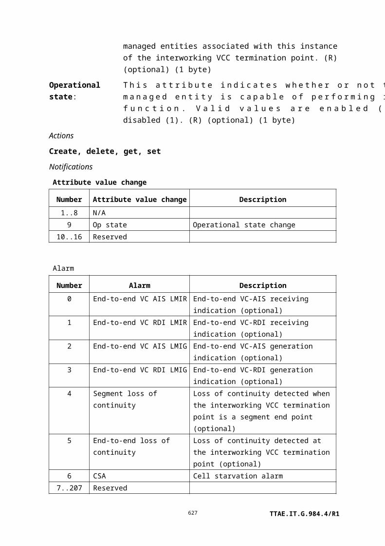
Field Byte 8 7 6 5 4 3 2 1 Comments
28-29 Ring-ground DC voltage, 2 s
complement, resolution 1 V.
Valid only if byte 18 bbb =
xx1.
30 Tip-ground AC voltage, Vrms.
Valid only if byte 19 aaa = xx1.
31 Ring-ground AC voltage,
Vrms. Valid only if byte 19 bbb
= xx1.
32-33 Tip-ground DC resistance, kΩ.
Infinite resistance: 0xffff. Valid
only if byte 20 aaa = xx1.
34-35 Ring-ground DC resistance,
kΩ. Infinite resistance: 0xffff.
Valid only if byte 20 bbb =
xx1.
36-37 Tip-ring DC resistance, kΩ.
Infinite resistance: 0xffff. Valid
only if byte 21 aaa = xx1.
38 Ringer equivalence, in 0.1 REN
units. Valid only if byte 21
bbb = xx1.
39-40 Pointer to a general purpose
buffer ME. Valid only for
vendor-specific tests that
require a GP buffer.
41-45 0 0 0 0 0 0 0 0 padding
NOTE – Coding for 3 bit flag sets is as follows:
= 000 test not run;
= 010 fail, measurement not reported;
= 011 fail, measurement reported;
= 110 pass, measurement not reported;
= 111 pass, measurement reported.
Format for test action invoked against IP host config data entity class
TTAE.IT.G.984.4/R1627
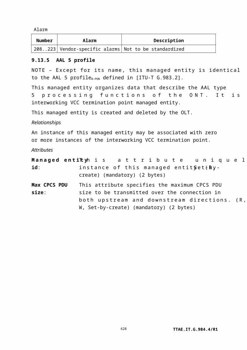
Field Byte 8 7 6 5 4 3 2 1 Comments
Transaction
identifier
6-7
Message type 8 0 0 0 DB = 0, AR = 0, AK = 0
bits 5-1: action = test result
Device identifier
type
9 0 0 0 0 1 0 1 0 OMCI = 0x0A
Message identifier 10-11 Entity class.
NOTE – This format applies to
entity class IP host config data.
12 MS byte entity instance
13 LS byte entity instance
Message contents 14 0 0 0 0 0 x x x Test result:
xxx = 000: timed out, no
response
xxx = 001: ICMP echo
responses
attached
xxx = 010: ICMP time
exceeded
responses
attached
xxx = 011: Unexpected ICMP
response
xxx = 100-111: Reserved
15 0 0 0 y y y y y yyyyy: number of meaningful
bytes in the remainder of the test
result message
If xxx = 001 (echo response – ping), the remainder of the message contains the following content. How many echo requests are sent and the resolution of the delay measurement are specific to a vendor's implementation. The special value 0xFFFF indicates a lost response.
16-17 16-bit measurement of response
delay 1, expressed in ms
18-19 16-bit measurement of response
delay 2, expressed in ms
… Etc.
…-45 0 0 0 0 0 0 0 0 Padding
TTAE.IT.G.984.4/R1628

If xxx = 010 (time exceeded – traceroute), the remainder of the message contains the following content. In PON applications, it is not expected that a route trace will exceed the available space in the message, but if it does, the more distant responses should be dropped.
16-19 IP address of nearest neighbour
20-23 IP address of second nearest
neighbour
… Etc.
…-45 0 0 0 0 0 0 0 0 Padding
If xxx = 011 (unexpected ICMP response), the remainder of the message contains the following content:
16 Type
17 Code
18-19 Checksum
20-23 Bytes 5-8 of ICMP message
(meaning depends on type/code)
24-45 Internet header + 64 bits of
original datagram (truncated)
Format for optical line supervision test action invoked against ANI-G entity class
Field Byte 8 7 6 5 4 3 2 1 Comments
Transaction
identifier
6-7
Message type 8 0 0 0 DB = 0, AR = 0, AK =0
bits 5-1: action = test result
Device identifier
type
9 0 0 0 0 1 0 1 0 OMCI = 0x0A
Message identifier 10-11 Entity class.
NOTE – This message format
pertains to ANI-G entity class.
12 MS byte entity instance
13 LS byte entity instance
Message contents 14 0 0 0 0 0 0 0 1 Type = 1, power feed voltage
15-16 V, 2s complement, 20 mV
resolution
TTAE.IT.G.984.4/R1629

Field Byte 8 7 6 5 4 3 2 1 Comments
17 0 0 0 0 0 0 1 1 Type = 3, received optical power
18-19 dBµW, 2s complement, 0.002 dB
resolution
20 0 0 0 0 0 1 0 1 Type = 5, transmitted optical
power,
21-22 dBµW, 2s complement, 0.002 dB
resolution
23 0 0 0 0 1 0 0 1 Type = 9, laser bias current
24-25 Unsigned integer, 2 µA resolution
26 0 0 0 0 1 1 0 0 Type 12, temperature, degrees
27-28 2s complement, 1/256 degree C
resolution
29-45 Padding
NOTE – Unsupported tests are indicated with test type indicator 0 and 2 bytes of 0 data.
II.2.46 Get current data
Field Byte 8 7 6 5 4 3 2 1 Comments
Transaction
identifier
6-7
Message type 8 0 1 0 DB = 0, AR = 1, AK = 0
bits 5-1: action = get current data
Device identifier
type
9 0 0 0 0 1 0 1 0 OMCI = 0x0A
Message identifier 10-11 Entity class
12 MS byte entity instance
13 LS byte entity instance
Message contents 14 MS byte attribute mask
15 LS byte attribute mask
16-45 0 0 0 0 0 0 0 0 Padding
Based on the size of the message contents field, the aggregate size of the attributes requested by a single get current data command should not exceed 25 bytes.
II.2.47 Get current data response
TTAE.IT.G.984.4/R1630

Field Byte 8 7 6 5 4 3 2 1 Comments
Transaction
identifier
6-7
Message type 8 0 0 1 DB = 0, AR = 0, AK = 1
bits 5-1: action = get current data
Device identifier
type
9 0 0 0 0 1 0 1 0 OMCI = 0x0A
Message identifier 10-11 Entity class
12 MS byte entity instance
13 LS byte entity instance
Message contents 14 0 0 0 0 x x x x Result, reason
0000 = command processed
successfully
0001 = command processing error
0010 = command not supported
0011 = parameter error
0100 = unknown managed entity
0101 = unknown managed entity
instance
0110 = device busy
1001 = attribute(s) failed or
unknown
15 MS byte attribute mask
16 LS byte attribute mask
17 Attribute value of first attribute
included (size depending on the
type of attribute)
…
Attribute value of last attribute
included (size depending on the
type of attribute)
xx-41 0 0 0 0 0 0 0 0 Padding
42 Optional attribute mask (attributes
1-8), used with 1001 encoding:
0 = default
1 = unsupported attribute
TTAE.IT.G.984.4/R1631

Field Byte 8 7 6 5 4 3 2 1 Comments
43 Optional attribute mask (attributes
9-16), used with 1001 encoding:
0 = default
1 = unsupported attribute
44 Attribute execution mask
(attributes 1-8), used with 1001
encoding:
0 = default
1 = failed attribute
45 Attribute execution mask
(attributes 9-16), used with 1001
encoding:
0 = default
1 = failed attribute
Bytes 42 to 45 are always reserved for the optional attribute and attribute execution masks; however, the content of these bytes is only valid in conjunction with the 1001 encoding used to indicate failed or unknown attributes.
II.3 Extended OMCI message layout
Extended OMCI messages may be up to 1980 bytes long, including headers. The previous discussion of oversize get next messages remains applicable, although problems are less likely to occur in practice.
II.3.1 Create
Field Byte 8 7 6 5 4 3 2 1 Comments
Transaction correlation
identifier
1-2
Message type 3 0 1 0 DB = 0, AR = 1, AK = 0
bits 5-1: action = create
Device identifier 4 0 0 0 0 1 0 1 1 Extended OMCI = 0x0B
Managed entity
identifier
5-6 Entity class
7 MS byte entity instance
8 LS byte entity instance
TTAE.IT.G.984.4/R1632

Field Byte 8 7 6 5 4 3 2 1 Comments
Message contents
length
9-10 Size of message contents field,
bytes
Message contents 11-n Value of first set-by-create
attribute, NOT the ME ID (size
depending on the type of attribute)
…
Value of last set-by-create
attribute
The contents of the create message apply only to attributes that are defined to be set-by-create. Writeable attributes that are not set-by-create are not permitted in a create message. Thus, the first byte of the message contents field begins with the value of the first set-by-create attribute and so forth. Space for each set-by-create attribute must be allocated in the create message, even if the attribute is optional. When an optional attribute is not to be instantiated, the placeholder value to be entered into this space is specific to the definition of each attribute.
II.3.2 Create response
Field Byte 8 7 6 5 4 3 2 1 Comments
Transaction correlation
identifier
1-2
Message type 3 0 0 1 DB = 0, AR = 0, AK = 1
bits 5-1: action = create
Device identifier 4 0 0 0 0 1 0 1 1 Extended OMCI = 0x0B
Managed entity
identifier
5-6 Entity class
7 MS byte entity instance
8 LS byte entity instance
Message contents
length
9-10 Size of message contents field,
bytes
TTAE.IT.G.984.4/R1633

Field Byte 8 7 6 5 4 3 2 1 Comments
Message contents 11 0 0 0 0 x x x x Result, reason
0000 command processed
successfully
0001 command processing
error
0010 command not supported
0011 parameter error
0100 unknown managed entity
0101 unknown managed entity
instance
0110 device busy
0111 instance exists
12 Attribute execution mask (attributes
1-8), used when result,
reason = 0011
0 attribute ok
1 illegal attribute value
13 Attribute execution mask (attributes
9-16), used when result,
reason = 0011
0 attribute ok
1 illegal attribute value
NOTE – If the result, reason code is not 0011, the attribute execution mask in bytes 12-13 is
omitted.
II.3.3 This clause is intentionally left blank
II.3.4 This clause is intentionally left blank
II.3.5 Delete
Field Byte 8 7 6 5 4 3 2 1 Comments
Transaction correlation
identifier
1-2
Message type 3 0 1 0 DB = 0, AR = 1, AK = 0
bits 5-1: action = delete
Device identifier 4 0 0 0 0 1 0 1 1 Extended OMCI = 0x0B
TTAE.IT.G.984.4/R1634

Field Byte 8 7 6 5 4 3 2 1 Comments
Managed entity
identifier
5-6 Entity class
7 MS byte entity instance
8 LS byte entity instance
Message contents
length
9-10 Size of message contents field = 0
II.3.6 Delete response
Field Byte 8 7 6 5 4 3 2 1 Comments
Transaction correlation
identifier
1-2
Message type 3 0 0 1 DB = 0, AR = 0, AK = 1
bits 5-1: action = delete
Device identifier 4 0 0 0 0 1 0 1 1 Extended OMCI = 0x0B
Managed entity
identifier
5-6 Entity class
7 MS byte entity instance
8 LS byte entity instance
Message contents
length
9-10 Size of message contents field = 1 byte
Message contents 11 Result, reason
0000 command processed
successfully
0001 command processing error
0010 command not supported
0011 parameter error
0100 unknown managed entity
0101 unknown managed entity
instance
0110 device busy
TTAE.IT.G.984.4/R1635

II.3.7 This clause is intentionally left blank
II.3.8 This clause is intentionally left blank
II.3.9 Set
Field Byte 8 7 6 5 4 3 2 1 Comments
Transaction correlation
identifier
1-2
Message type 3 0 1 0 DB = 0, AR = 1, AK = 0
bits 5-1: action = set
Device identifier 4 0 0 0 0 1 0 1 1 Extended OMCI = 0x0B
Managed entity
identifier
5-6 Entity class
7 MS byte entity instance
8 LS byte entity instance
Message contents
length
9-10 Size of message contents field, bytes
Message contents 11 Attributes mask (attributes 1-8)
12 Attributes mask (attributes 9-16)
13-n Value of first attribute to set (size
depending on the type of attribute)
…
Value of last attribute to set
II.3.10 Set response
Field Byte 8 7 6 5 4 3 2 1 Comments
Transaction correlation
identifier
1-2
Message type 3 0 0 1 DB = 0, AR = 0, AK = 1
bits 5-1: action = set
Device identifier 4 0 0 0 0 1 0 1 1 Extended OMCI = 0x0B
Managed entity
identifier
5-6 Entity class
7 MS byte entity instance
8 LS byte entity instance
TTAE.IT.G.984.4/R1636

Field Byte 8 7 6 5 4 3 2 1 Comments
Message contents
length
9-10 Size of message contents field,
bytes
Message contents 11 0 0 0 0 x x x x Result, reason
0000 command processed
successfully
0001 command processing
error
0010 command not supported
0011 parameter error
0100 unknown managed entity
0101 unknown managed entity
instance
0110 device busy
1001 attribute(s) failed or
unknown
12 Optional-attribute mask (attributes
1-8), used with 1001 encoding:
0 default
1 unsupported attribute
13 Optional-attribute mask (attributes
9-16), used with 1001 encoding:
0 default
1 unsupported attribute
14 Attribute execution mask
(attributes 1-8), used with 1001
encoding:
0 default
1 failed attribute
15 Attribute execution mask
(attributes 9-16), used with 1001
encoding:
0 default
1 failed attribute
NOTE – If the result code is not 1001, the attribute masks in bytes 12-15 are omitted.
II.3.11 Get
TTAE.IT.G.984.4/R1637

Field Byte 8 7 6 5 4 3 2 1 Comments
Transaction correlation
identifier
1-2
Message type 3 0 1 0 DB = 0, AR = 1, AK = 0
bits 5-1: action = get
Device identifier 4 0 0 0 0 1 0 1 1 Extended OMCI = 0x0B
Managed entity
identifier
5-6 Entity class
7 MS byte entity instance
8 LS byte entity instance
Message contents
length
9-10 Size of message contents
field = 2 bytes
Message contents 11 Attributes mask (attributes 1-8)
12 Attributes mask (attributes 9-16)
II.3.12 Get response
Field Byte 8 7 6 5 4 3 2 1 Comments
Transaction correlation
identifier
1-2
Message type 3 0 0 1 DB = 0, AR = 0, AK = 1
bits 5-1: action = get
Device identifier 4 0 0 0 0 1 0 1 1 Extended OMCI = 0x0B
Managed entity
identifier
5-6 Entity class
7 MS byte entity instance
8 LS byte entity instance
Message contents
length
9-10 Size of message contents field,
bytes
TTAE.IT.G.984.4/R1638

Field Byte 8 7 6 5 4 3 2 1 Comments
Message contents 11 0 0 0 0 x x x x Result, reason
0000 command processed
successfully
0001 command processing
error
0010 command not supported
0011 parameter error
0100 unknown managed entity
0101 unknown managed entity
instance
0110 device busy
1001 attribute(s) failed or
unknown
12 Attribute mask (attributes 1-8)
13 Attribute mask (attributes 9-16)
14 Optional-attribute mask (attributes
1-8), used with 1001 encoding:
0 default
1 unsupported attribute
15 Optional-attribute mask (attributes
9-16), used with 1001 encoding:
0 default
1 unsupported attribute
16 Attribute execution mask
(attributes 1-8), used with 1001
encoding:
0 default
1 failed attribute
17 Attribute execution mask
(attributes 9-16), used with 1001
encoding:
0 default
1 failed attribute
18-n Value of first attribute included
(size depending on the type of
attribute)
TTAE.IT.G.984.4/R1639

Field Byte 8 7 6 5 4 3 2 1 Comments
…
Value of last attribute included
Bytes 14-17 are reserved for the optional-attribute and attribute execution masks; however, the content of these bytes is only valid in conjunction with result code 1001 used to indicate failed or unknown attributes. When the result code is not 1001, these bytes should be set to 0 by the ONT transmitter and ignored by the OLT receiver.
NOTE – The position of these bytes differs from that in the baseline get response message.
When the OLT wishes to retrieve a table attribute, i.e., an attribute whose size is, or might be, larger than the space available in one OMCI baseline message, the ONT indicates the size of that attribute in bytes, rather than its value. The size is conveyed as four bytes in the value field for that attribute, with the attribute execution mask set to indicate that the attribute is included. The OLT should then use a sequence of get next messages to retrieve such an attribute. This convention also pertains to extended OMCI messages, even though some table attributes might fit into an extended get response message.
II.3.13 This clause is intentionally left blank
II.3.14 This clause is intentionally left blank
II.3.15 Get all alarms
Field Byte 8 7 6 5 4 3 2 1 Comments
Transaction
correlation identifier
1-2
Message type 3 0 1 0 DB = 0, AR = 1, AK = 0
bits 5-1: action = get all alarms
Device identifier 4 0 0 0 0 1 0 1 1 Extended OMCI = 0x0B
Managed entity
identifier
5-6 Entity class = ONT data
7 MS byte entity instance
8 LS byte entity instance
Message contents
length
9-10 Size of message contents
field = 1
TTAE.IT.G.984.4/R1640

Field Byte 8 7 6 5 4 3 2 1 Comments
Message contents 11 0 0 0 0 0 0 0 x x = alarm retrieval mode
0 Get all alarms regardless of
ARC status
1 Get all alarms not currently
under
ARC
II.3.16 Get all alarms response
The semantics of the message contents differs from that of the corresponding baseline OMCI message. In the extended OMCI get all alarms next response, a number of managed entity instances can be reported in a single message, so the get all alarms response message contents do not indicate the count of managed entity instances, but rather specify the number of get all alarms next messages required.
Field Byte 8 7 6 5 4 3 2 1 Comments
Transaction correlation
identifier
1-2
Message type 3 0 0 1 DB = 0, AR = 0, AK = 1
bits 5-1: action = get all alarms
Device identifier 4 0 0 0 0 1 0 1 1 Extended OMCI = 0x0B
Managed entity
identifier
5-6 Entity class = ONT data
7 MS byte entity instance
8 LS byte entity instance
Message contents
length
9-10 Size of message contents field = 2
Message contents 11 MS byte of the number of get all
alarms next messages required
12 LS byte of the number of get all
alarms next messages required
II.3.17 Get all alarms next
TTAE.IT.G.984.4/R1641

Field Byte 8 7 6 5 4 3 2 1 Comments
Transaction correlation
identifier
1-2
Message type 3 0 1 0 DB = 0, AR = 1, AK = 0
bits 5-1: action = get all alarms
next
Device identifier 4 0 0 0 0 1 0 1 1 Extended OMCI = 0x0B
Managed entity
identifier
5-6 Entity class = ONT data
7 MS byte entity instance
8 LS byte entity instance
Message contents
length
9-10 Size of message contents field = 2
Message contents 11 MS byte of command sequence
number
12 LS byte of command sequence
number
Command sequence numbers start from 0.
II.3.18 Get all alarms next response
This message differs from the equivalent baseline message in that a number of managed entity alarm bit maps may be returned within a single message.
Field Byte 8 7 6 5 4 3 2 1 Comments
Transaction correlation
identifier
1-2
Message type 3 0 0 1 DB = 0, AR = 0, AK = 1
bits 5-1: action = get all alarms
next
Device identifier 4 0 0 0 0 1 0 1 1 Extended OMCI = 0x0B
Managed entity
identifier
5-6 Entity class = ONT data
7 MS byte entity instance
8 LS byte entity instance
Message contents
length
9-10 Size of message contents field
including all sub-parts, bytes
TTAE.IT.G.984.4/R1642

Field Byte 8 7 6 5 4 3 2 1 Comments
Message contents 1
11-12
Entity class whose alarms are reported
13 MS byte entity instance whose
alarms are reported
14 LS byte entity instance whose
alarms are reported
15-42 x x x x x x x x Bit map alarms
Message contents 2 43-44 Entity class whose alarms are
reported
45 MS byte entity instance whose
alarms are reported
46 LS byte entity instance whose
alarms are reported
47-74 x x x x x x x x Bit map alarms
… Further managed entity alarm
masks as neededMessage contents n
The bit map used in the get all alarms next response for a given managed entity class is identical to the bit map used in the alarm notifications for that managed entity class.
If the ONT receives a get all alarms next request message whose command sequence number is out of range, the get all alarms next response message should contain a null message contents field.
II.3.19 MIB upload
Field Byte 8 7 6 5 4 3 2 1 Comments
Transaction correlation
identifier
1-2
Message type 3 0 1 0 DB = 0, AR = 1, AK = 0
bits 5-1: action = MIB upload
Device identifier 4 0 0 0 0 1 0 1 1 Extended OMCI = 0x0B
Managed entity
identifier
5-6 Entity class = ONT data
7 MS byte entity instance
8 LS byte entity instance
TTAE.IT.G.984.4/R1643

Field Byte 8 7 6 5 4 3 2 1 Comments
Message contents
length
9-10 Size of message contents field = 0
II.3.20 MIB upload response
Field Byte 8 7 6 5 4 3 2 1 Comments
Transaction correlation
identifier
1-2
Message type 3 0 0 1 DB = 0, AR = 0, AK = 1
bits 5-1: action = MIB upload
Device identifier 4 0 0 0 0 1 0 1 1 Extended OMCI = 0x0B
Managed entity
identifier
5-6 Entity class = ONT data
7 MS byte entity instance
8 LS byte entity instance
Message contents
length
9-10 Size of message contents field = 2
Message contents 11 MS byte of the number of MIB
upload next commands required
12 LS byte of the number of MIB
upload next commands required
II.3.21 MIB upload next
Field Byte 8 7 6 5 4 3 2 1 Comments
Transaction correlation
identifier
1-2
Message type 3 0 1 0 DB = 0, AR = 1, AK = 0
bits 5-1: action = MIB upload next
Device identifier 4 0 0 0 0 1 0 1 1 Extended OMCI = 0x0B
Managed entity
identifier
5-6 Entity class = ONT data
7 MS byte entity instance
8 LS byte entity instance
TTAE.IT.G.984.4/R1644

Field Byte 8 7 6 5 4 3 2 1 Comments
Message contents
length
9-10 Size of message contents field = 2
Message contents 11 MS byte of command sequence
number
12 LS byte of command sequence
number
Command sequence numbers start from 0.
II.3.22 MIB upload next response
Field Byte 8 7 6 5 4 3 2 1 Comments
Transaction correlation
identifier
1-2
Message type 3 0 0 1 DB = 0, AR = 0, AK = 1
bits 5-1: action = MIB upload next
Device identifier 4 0 0 0 0 1 0 1 1 Extended OMCI = 0x0B
Managed entity
identifier
5-6 Entity class = ONT data
7 MS byte entity instance
8 LS byte entity instance
Message contents
length
9-10 Size of message contents field
including all sub-fields, bytes
Message contents, ME
instance 1
11-12 Size of ME instance 1 attribute
values included (excluding bytes
11-18), bytes
13-14 Entity class of ME instance 1
15 MS byte entity instance
16 LS byte entity instance
17 Attribute mask (attributes 1-8)
18 Attribute mask (attributes 9-16)
19-n Value of first attribute (size
depending on the type of the
attribute)
...
TTAE.IT.G.984.4/R1645

Field Byte 8 7 6 5 4 3 2 1 Comments
Value of last attribute
Message contents, ME
instance 2
Content of ME instance 2, defined
as above.
… …
Message contents, ME
instance k
Content of ME instance k, defined
as above.
Note that, if not all attributes of a managed entity fit within one MIB upload next response message, the attributes are split over several messages. The OLT can use the information in the attribute mask to determine which attribute values are reported in which MIB upload next response message.
Thus, a single extended MIB upload next response message must contain an integer number of attribute values. A message may contain leading or trailing fragments of ME instances and any number of complete ME instances.
If the ONT receives a MIB upload next request message whose command sequence number is out of range, it should respond with a message containing no message contents field. This is also the appropriate response if the ONT times out (one minute) from the most recent MIB upload next or MIB upload request from the OLT.
II.3.23 MIB reset
Field Byte 8 7 6 5 4 3 2 1 Comments
Transaction correlation
identifier
1-2
Message type 3 0 1 0 DB = 0, AR = 1, AK = 0
bits 5-1: action = MIB reset
Device identifier 4 0 0 0 0 1 0 1 1 Extended OMCI = 0x0B
Managed entity
identifier
5-6 Entity class = ONT data
7 MS byte entity instance
8 LS byte entity instance
Message contents
length
9-10 Size of message contents field = 0
II.3.24 MIB reset response
TTAE.IT.G.984.4/R1646

Field Byte 8 7 6 5 4 3 2 1 Comments
Transaction correlation
identifier
1-2
Message type 3 0 0 1 DB = 0, AR = 0, AK = 1
bits 5-1: action = MIB reset
Device identifier 4 0 0 0 0 1 0 1 1 Extended OMCI = 0x0B
Managed entity
identifier
5-6 Entity class = ONT data
7 MS byte entity instance
8 LS byte entity instance
Message contents
length
9-10 Size of message contents
field = 1
Message contents 11 0 0 0 0 x x x x Result, reason
0000 command processed
successfully
0001 command processing
error
0010 command not
supported
0011 parameter error
0100 unknown managed
entity
0101 unknown managed
entity
instance
0110 device busy
II.3.25 Alarm
Field Byte 8 7 6 5 4 3 2 1 Comments
Transaction correlation
identifier
1-2
Message type 3 0 0 0 DB = 0, AR = 0, AK = 0
bits 5-1: action = alarm
Device identifier 4 0 0 0 0 1 0 1 1 Extended OMCI = 0x0B
Managed entity
identifier
5-6 Entity class
TTAE.IT.G.984.4/R1647

Field Byte 8 7 6 5 4 3 2 1 Comments
7 MS byte entity instance
8 LS byte entity instance
Message contents
length
9-10 Size of message contents field,
bytes
Message contents 11 Alarm mask
…
38 Alarm mask
39 Alarm sequence number
II.3.26 Attribute value change
Field Byte 8 7 6 5 4 3 2 1 Comments
Transaction correlation
identifier
1-2
Message type 3 0 0 0 DB = 0, AR = 0, AK = 0
bits 5-1: action = attribute value
change
Device identifier 4 0 0 0 0 1 0 1 1 Extended OMCI = 0x0B
Managed entity
identifier
5-6 Entity class
7 MS byte entity instance
8 LS byte entity instance
Message contents
length
9-10 Size of message contents field,
bytes
Message contents 11 MS byte attribute mask
12 LS byte attribute mask
13-n Value of first changed attribute
(size depending on the type of
attribute)
...
Value of last changed attribute
The AVC message for a table attribute contains no attribute value, only a mask, and the ONT creates no snapshot of the table. If the OLT wishes to obtain the new value, it must do a get operation, followed by the required number of get next operations.
TTAE.IT.G.984.4/R1648

II.3.27 Test
The format of the test message is specific to the target entity class. Several formats are defined. Future test extensions for a given entity class can be supported by adding additional encodings to presently unused bits or bytes. Future specification of tests for other entity classes may use an existing format or may define new formats for the test message. These extension mechanisms allow future tests to be supported without changing the principle of operation.
Format for ONT-G, ANI-G, RE ANI-G, PPTP RE UNI, RE upstream amplifier, RE downstream amplifier and circuit pack entity classes
Field Byte 8 7 6 5 4 3 2 1 Comments
Transaction correlation
identifier
1-2
Message type 3 0 1 0 DB = 0, AR = 1, AK = 0
bits 5-1: action = test
Device identifier 4 0 0 0 0 1 0 1 1 Extended OMCI = 0x0B
Managed entity
identifier
5-6 Entity class.
NOTE – This format applies to
entity classes ONT-G, ANI-G, RE
ANI-G, PPTP RE UNI, RE
upstream amplifier, RE
downstream amplifier and circuit
pack.
7 MS byte entity instance
8 LS byte entity instance
Message contents
length
9-10 Size of message contents field = 1
Message contents 11 0 0 0 0 x x x x xxxx = select test
0000..0110 Reserved for
future use
0111 Self test
1000..1111 Vendor-specific
use. See
description
related to the test
result message.
TTAE.IT.G.984.4/R1649

Format for IP host config data entity class
Field Byte 8 7 6 5 4 3 2 1 Comments
Transaction correlation
identifier
1-2
Message type 3 0 1 0 DB=0, AR=1, AK=0
Bits 5-1: action=test
Device identifier 4 0 0 0 0 1 0 1 1 Extended OMCI = 0x0B
Managed entity
identifier
5-6 Entity class.
NOTE – This format applies to
entity class IP host config data.
7 MS byte entity instance
8 LS byte entity instance
Message contents
length
9-10 Size of message contents field,
bytes
Message contents 11 0 0 0 0 x x x x xxxx = select test
0001 Ping
0010 Traceroute
0010..0111 Reserved
1000..1111 Vendor-
specific use.
The ICMP message is intended to
be sent from the ONT upstream
toward the network. See discussion
related to the test result message.
12-15 IP address of target
Format for POTS UNI and PPTP ISDN UNI entity classes
This message supports two basic categories of test operation, a defined set of tests that look in and out from the POTS port, and a set of codepoints that may be used for vendor-specific tests. The latter category is further subdivided into codepoints that return test results in a general purpose buffer ME, using the test result message primarily as an event trigger to signal test completion, and codepoints that return all test results in an ordinary test result message. If it is needed, the OLT must create the general purpose buffer managed entity before initiating the test action.
Note that a single message can be used to initiate multiple tests on a given ME if desired.
TTAE.IT.G.984.4/R1650

Bytes 12-25 are used by the dial tone make-break test. A zero value for a timer causes the ONT to use its built-in defaults. As many as three dial tone frequencies can be specified, or omitted by setting their values to 0. Other fields are also omitted with the value 0, or controlled by flags. An ONT can support the dial tone test with internal defaults only, and is not required to support any of the attributes of bytes 12-25. Likewise, an ONT can use internal defaults for drop test, rather than the values given in bytes 26-35. The capabilities of an ONT are documented by the vendor and known through administrative practices.
Field Byte 8 7 6 5 4 3 2 1 Comments
Transaction correlation
identifier
1-2
Message type 3 0 1 0 DB = 0, AR = 1, AK = 0
Bits 5-1: action = test
Device identifier 4 0 0 0 0 1 0 1 1 Extended OMCI = 0x0B
Managed entity
identifier
5-6 Entity class
NOTE – This format applies to
entity classes PPTP POTS UNI and
PPTP ISDN UNI.
7 MS byte entity instance
8 LS byte entity instance
Message contents
length
9-10 Size of message contents field,
bytes
TTAE.IT.G.984.4/R1651
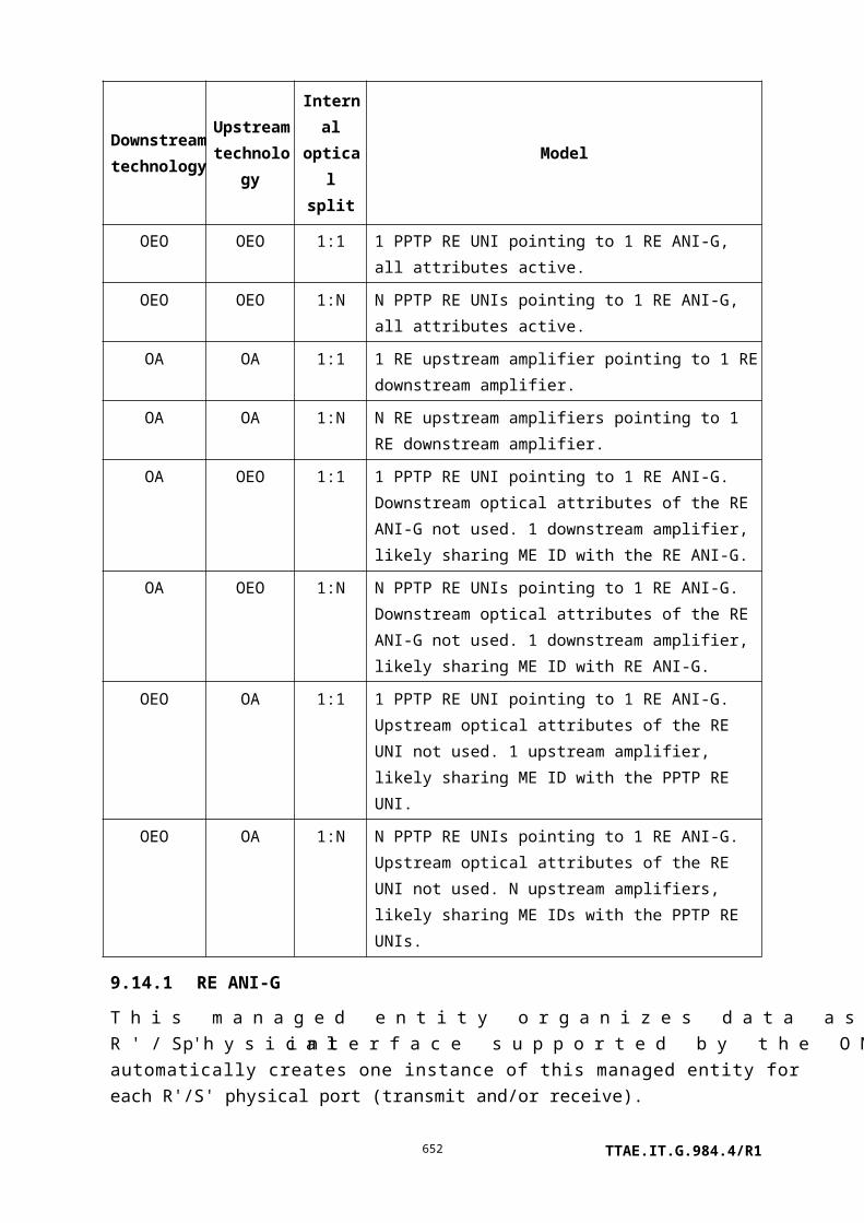
Field Byte 8 7 6 5 4 3 2 1 Comments
Message contents 11 a 0 0 0 x x x x a – test mode
0 normal; deny test if line
busy
1 forced mode
xxxx = select test
0000 all MLT tests
0001 hazardous potential
0010 foreign EMF
0011 resistive faults
0100 receiver off-hook
0101 ringer
0110 NT1 dc signature test
0111 self test
1000 dial tone make-break test
1001..1011 vendor-specific
test, all results returned in test
results message
1100..1111 vendor-specific
test, test results returned in
general purpose buffer
ME. The ONT should deny a
test operation command in
this range if bytes 36..37 do
not point to a GP buffer.
12 DBDT timer T1 (slow dial tone
threshold), in units of 0.1 seconds.
Range 0.1 to 6.0 seconds.
13 DBDT timer T2 (no dial tone
threshold), in units of 0.1 seconds.
Range 1.0 to 10.0 seconds.
14 DBDT timer T3 (slow break dial
tone threshold), in units of 0.1
seconds. Range 0.1 to 3.0 seconds.
15 DBDT timer T4 (no break dial tone
threshold), in units of 0.1 seconds.
Range 1.0 to 3.0 seconds.
TTAE.IT.G.984.4/R1652

Field Byte 8 7 6 5 4 3 2 1 Comments
16 d p DBDT control byte
d: dialled digit
1 dialled digit specified in
byte 17
0 use default digit
p = pulse (1) or tone (0) dialling
17 Digit to be dialled, ASCII character
in range "0"-"9", "*", "#".
18-19 Dial tone frequency 1, in units of
Hz
20-21 Dial tone frequency 2, in units of
Hz. 0 = unused (i.e., if only one
tone is specified).
22-23 Dial tone frequency 3, in units of
Hz. 0 = unused (i.e., if only one or
two tones are specified).
24 Dial tone power threshold, absolute
value, 0.1 dB resolution, range
[–]0.1 to [–]25.3 dBm0, e.g.,
–13 dBm0 = 0x82.
0 = unspecified.
25 Idle channel power threshold,
absolute value, 1 dB resolution,
range [–]1 to
[–]90 dBm0. 0 = unspecified.
26 DC hazardous voltage threshold,
absolute value, volts.
0 = unspecified.
27 AC hazardous voltage threshold,
volts RMS. 0 = unspecified.
28 DC foreign voltage threshold,
absolute value, volts.
0 = unspecified.
29 AC foreign voltage threshold, volts
RMS. 0 = unspecified.
TTAE.IT.G.984.4/R1653

Field Byte 8 7 6 5 4 3 2 1 Comments
30 Tip-ground and ring-ground
resistance threshold, k
0 = unspecified.
31 Tip-ring resistance threshold, k.
0 = unspecified.
32-33 Ringer equivalence minimum
threshold, in 0.01 REN units.
0 = unspecified.
34-35 Ringer equivalence maximum
threshold, in 0.01 REN units.
0 = unspecified.
36-37 Pointer to a general purpose buffer
ME, used to return vendor-specific
test results.
Format for dot1ag MEP entity class, loopback test
Field Byte 8 7 6 5 4 3 2 1 Comments
Transaction correlation
identifier
1-2
Message type 3 0 1 0 DB = 0, AR = 1, AK = 0
Bits 5-1: action = test
Device identifier 4 0 0 0 0 1 0 1 1 Extended OMCI = 0x0B
Managed entity
identifier
5-6 Entity class
NOTE – This format applies to the
dot1ag MEP entity class.
7 MS byte entity instance
8 LS byte entity instance
Message contents
length
9-10 Size of message contents field,
bytes
TTAE.IT.G.984.4/R1654

Field Byte 8 7 6 5 4 3 2 1 Comments
Message contents 11 0 0 0 0 0 0 0 x x=select test
0: Ethernet loopback test
1: IEEE 802.1ag link trace test (see
separate format description below)
Other values reserved
12 0 0 0 c p p p d If c = 1, the value of the MEP's
CCM and LTM priority attribute is
used, with drop eligibility false.
If c = 0, pppd represents the
priority (p bits) and drop eligibility
fields of the transmitted LBM
frame.
13-18 MAC address of target MHF or
MEP, or 0 if the destination MEP
ID is to be used instead. [b-
IEEE 802.1ag] specifies unicast
addresses; ITU-T Y.1731 also
allows for multicast.
19-20 Destination MEP ID, in the range
1..8191, or 0 if the MAC address in
bytes 13..18 is to be used instead.
21-22 Repetition count, range 1..1024.
This governs how many LBMs are
generated. The rate at which LBMs
are generated is not specified. If 5
seconds elapses with no LBRs
received, the test aborts.
23-24 These four fields are pointers to as
many as four-octet string MEs,
which are concatenated to form an
octet string of up to 1500 bytes.
The string is packaged into a data
25-26
27-28
TTAE.IT.G.984.4/R1655

Field Byte 8 7 6 5 4 3 2 1 Comments
TLV and transmitted as part of the
LBM. If all four fields are null
pointers, no data TLV is sent. If
only one octet string is needed, it
should be specified in bytes 23..24,
etc., with null pointers in the
higher-numbered bytes of the test
message.
29-30
Format for dot1ag MEP entity class, linktrace test
Field Byte 8 7 6 5 4 3 2 1 Comments
Transaction correlation
identifier
1-2
Message type 3 0 1 0 DB = 0, AR = 1, AK = 0
Bits 5-1: action = test
Device identifier 4 0 0 0 0 1 0 1 1 Extended OMCI = 0x0B
Managed entity
identifier
5-6 Entity class
NOTE – This format applies to the
dot1ag MEP entity class
7 MS byte entity instance
8 LS byte entity instance
Message contents
length
9-10 Size of message contents field,
bytes
Message contents 11 0 0 0 0 0 0 0 x x=select test
0: Ethernet loopback test (see
separate format description above)
1: IEEE 802.1ag link trace test
Other values reserved
12 f 0 0 0 0 0 0 0 Flags, a bit mask
f: Use FDB only. When 1, the
bridge uses only its normal MAC
forwarding tables for forwarding.
When 0, the bridge may also
consult its MIP CCM database to
determine the forwarding port.
TTAE.IT.G.984.4/R1656

Field Byte 8 7 6 5 4 3 2 1 Comments
13-18 Unicast MAC address of target
MHF or MEP, or 0 if the
destination MEP ID is to be used
instead.
19-20 Destination MEP ID, in the range
1..8191, or 0 if the unicast MAC
address in bytes 13..18 is to be used
instead.
21 Max hops count – specifies initial
TTL (time to live); limits the
number of relay stages through
which the LTM is forwarded before
being discarded, and the number of
LTRs that may be returned. [b-
IEEE 802.1ag] recommends a
default value of 64.
22-23 Pointer to a general purpose buffer
ME, used to return the link trace
results. The ONT should deny the
test operation command if this field
is a null or an invalid pointer.
II.3.28 Test response
If an ONT does not support all tests requested in byte 11 of the test request message, it should not execute any test and should respond with result 0010, command not supported. If an ONT supports all of the requested tests but cannot support one or more of the explicitly specified threshold attributes, it should not execute any test and should respond with result 0011, parameter error. The test command could then be re-issued with different thresholds or with default thresholds, and would be expected to succeed.
Field Byte 8 7 6 5 4 3 2 1 Comments
Transaction correlation
identifier
1-2
Message type 3 0 0 1 DB = 0, AR = 0, AK = 1
bits 5-1: action = test
Device identifier 4 0 0 0 0 1 0 1 1 Extended OMCI = 0x0B
TTAE.IT.G.984.4/R1657

Field Byte 8 7 6 5 4 3 2 1 Comments
Managed entity
identifier
5-6 Entity class
7 MS byte entity instance
8 LS byte entity instance
Message contents
length
9-10 Size of message contents field = 1
Message contents 11 0 0 0 0 x x x x Result, reason
0000 command processed
successfully
0001 command processing
error
0010 command not supported
0011 parameter error
0100 unknown managed entity
0101 unknown managed entity
instance
0110 device busy
The test response message is an indication to the OLT that the test request is received and is being processed. The test outcome is reported by a subsequent autonomous test result message.
II.3.29 Start software download
When a file is to be downloaded to a single instance of the software image managed entity, the target ME id is specified in bytes 7..8. An optional feature permits the same file to be downloaded to a number of circuit packs by setting bytes 7..8 = 0xFFFF and specifying the software image ME ids in bytes 17-18, 19-20, etc.
Field Byte 8 7 6 5 4 3 2 1 Comments
Transaction correlation
identifier
1-2
Message type 3 0 1 0 DB = 0, AR = 1, AK = 0
bits 5-1: action = start software
download
Device identifier 4 0 0 0 0 1 0 1 1 Extended OMCI = 0x0B
Managed entity
identifier
5-6 Entity class = software image
TTAE.IT.G.984.4/R1658

Field Byte 8 7 6 5 4 3 2 1 Comments
7 MS byte of software image
instance
0 ONT-G
1..254 slot number
255 download to multiple
software image managed
entities
8 LS byte of software image instance
0 instance 0
1 instance 1
255 multiple download
Message contents
length
9-10 Size of message contents field,
bytes
Message contents 11 Window size – 1
12-15 Image size in bytes
16 Number of circuit packs to be
updated in parallel (value 1...9)
17 MS byte of software image
instance (slot number of circuit
pack)
18 LS byte of software image instance
(value 0..1)
19-xx Software image ME ids (same
format as bytes 17..18) for
additional simultaneous
downloads.
II.3.30 Start software download response
When a file is downloaded to a single software image ME, the response contains the target ME id in bytes 7..8, a result code in byte 11, and a window size counter-proposal (which may be the same as that suggested by the OLT in the original request). Bytes 13..N are omitted.
An ONT that supports the optional parallel download feature responds to a multiple download command with the full format shown below, where unused trailing image references may be omitted. If the ONT does not support the parallel download feature, it responds with result code 0b0101, unknown managed entity instance.
TTAE.IT.G.984.4/R1659

Field Byte 8 7 6 5 4 3 2 1 Comments
Transaction correlation
identifier
1-2
Message type 3 0 0 1 DB = 0, AR = 0, AK = 1
bits 5-1: action = start software
download
Device identifier 4 0 0 0 0 1 0 1 1 Extended OMCI = 0x0B
Managed entity
identifier
5-6 Entity class = software image
7 MS byte of software image
instance
0 ONT-G
1..254 slot number
255 download to multiple
software image managed
entities
8 LS byte of software image instance
0 instance 0
1 instance 1
255 multiple download
Message contents
length
9-10 Size of message contents field,
bytes
Message contents 11 0 0 0 0 x x x x Result, reason
0000 command processed
successfully
0001 command processing
error
0010 command not supported
0011 parameter error
0100 unknown managed entity
0101 unknown managed entity
instance
0110 device busy
12 Window size – 1
13 Number of instances responding
(value 0..9)
14-15 ME id of software image entity
TTAE.IT.G.984.4/R1660

Field Byte 8 7 6 5 4 3 2 1 Comments
instance (slot number plus instance
0..1)
16 Result, reason for bytes 14..15 –
same coding as byte 11
17-n Repeat coding of bytes 14..16 for
additional requested software
image instances.
II.3.31 Download section
Field Byte 8 7 6 5 4 3 2 1 Comments
Transaction correlation
identifier
1-2
Message type 3 0 x 0 DB = 0, AR = x, AK = 0
x = 0 no response expected
(section within a
window)
x = 1 response expected
(last section of a
window)
bits 5-1: action = sw download
section
Device identifier 4 0 0 0 0 1 0 1 1 Extended OMCI = 0x0B
Managed entity
identifier
5-6 Entity class = software image
7 MS byte of software image
instance
0 ONT-G
1..254 slot number
255 download to multiple
software image managed
entities
8 LS byte of software image instance
0 instance 0
1 instance 1
255 multiple download
TTAE.IT.G.984.4/R1661

Field Byte 8 7 6 5 4 3 2 1 Comments
Message contents
length
9-10 Size of message contents field,
bytes
Message contents 11 Download section number
12-n Software image data
II.3.32 Download section response
Field Byte 8 7 6 5 4 3 2 1 Comments
Transaction correlation
identifier
1-2
Message type 3 0 0 1 DB = 0, AR = 0, AK = 1
bits 5-1: action = sw download
section
Device identifier 4 0 0 0 0 1 0 1 1 Extended OMCI = 0x0B
Managed entity
identifier
5-6 Entity class = software image
7 MS byte of software image
instance
0 ONT-G
1..254 slot number
255 download to multiple
software image managed
entities
8 LS byte of software image instance
0 instance 0
1 instance 1
255 multiple download
Message contents
length
9-10 Size of message contents field = 2
Message contents 11 0 0 0 0 x x x x Result, reason
0000 command processed
successfully
0001 command processing
error
0010 command not supported
0011 parameter error
TTAE.IT.G.984.4/R1662

Field Byte 8 7 6 5 4 3 2 1 Comments
0100 unknown managed entity
0101 unknown managed entity
instance
0110 device busy
12 Download section number
II.3.33 End software download
The format of this command is similar to that of the start software download message. Bytes 19..n support the optional parallel download feature, and are omitted for download to a single target.
Field Byte 8 7 6 5 4 3 2 1 Comments
Transaction correlation
identifier
1-2
Message type 3 0 1 0 DB = 0, AR = 1, AK = 0
bits 5-1: action = end software
download
Device identifier 4 0 0 0 0 1 0 1 1 Extended OMCI = 0x0B
Managed entity
identifier
5-6 Entity class = software image
7 MS byte of software image
instance
0 ONT-G
1..254 slot number
255 download to multiple
software image managed
entities
8 LS byte of software image instance
0 instance 0
1 instance 1
255 multiple download
Message contents
length
9-10 Size of message contents field,
bytes
TTAE.IT.G.984.4/R1663

Field Byte 8 7 6 5 4 3 2 1 Comments
Message contents 11-14 CRC-32, computed over all bytes
of the software image (excluding
padding), as specified in
ITU-T I.363.5.
15-18 Image size in bytes
19 Number of parallel download
instances sent in this message
(value 1..9)
20 MS byte of software image
instance (slot number of circuit
pack)
21 LS byte of software image instance
(value 0..1)
22-xx Software image ME ids (same
format as bytes 20..21) for
additional simultaneous
downloads.
II.3.34 End software download response
The response message informs the OLT whether the download command was successful. If a single software image ME was targeted for download, byte 11 reports the result of the process. If a number of software images were targeted for parallel download, byte 11 reports device busy as long as any of the instances is busy writing the image to non-volatile store. Once the ONT has stored all images successfully, it responds to continued end software download commands with a 0 in byte 11 and a separate result for each software image ME.
Field Byte 8 7 6 5 4 3 2 1 Comments
Transaction correlation
identifier
1-2
Message type 3 0 0 1 DB = 0, AR = 0, AK = 1
bits 5-1: action = end software
download
Device identifier 4 0 0 0 0 1 0 1 1 Extended OMCI = 0x0B
TTAE.IT.G.984.4/R1664

Field Byte 8 7 6 5 4 3 2 1 Comments
Managed entity
identifier
5-6 Entity class = software image
7 MS byte of software image
instance
0 ONT-G
1..254 slot number
255 download to multiple
software image managed
entities
8 LS byte of software image instance
0 instance 0
1 instance 1
255 multiple download
Message contents
length
9-10 Size of message contents field,
bytes
Message contents 11 0 0 0 0 x x x x Result, reason
0000 command processed
successfully (CRC
correct)
0001 command processing
error
(CRC incorrect)
0100 unknown managed entity
0101 unknown managed entity
instance
0110 device busy
12 Number of instances responding
(value 0..9)
13-14 ME id of software image entity
instance (slot number plus instance
0..1)
15 Result, reason for bytes 13..14 –
same coding as byte 11
16-n Repeat coding of bytes 13..15 for
additional software image
instances.
TTAE.IT.G.984.4/R1665

II.3.35 Activate image
Field Byte 8 7 6 5 4 3 2 1 Comments
Transaction correlation
identifier
1-2
Message type 3 0 1 0 DB = 0, AR = 1, AK = 0
bits 5-1: action = activate image
Device identifier 4 0 0 0 0 1 0 1 1 Extended OMCI = 0x0B
Managed entity
identifier
5-6 Entity class = software image
7 MS byte entity instance
0 ONT-G
1..254 slot number
8 0 0 0 0 0 0 0 x LS byte entity instance
0 first instance
1 second instance
Message contents
length
9-10 Size of message contents field = 0
II.3.36 Activate image response
Field Byte 8 7 6 5 4 3 2 1 Comments
Transaction correlation
identifier
1-2
Message type 3 0 0 1 DB = 0, AR = 0, AK = 1
bits 5-1: action = activate image
Device identifier 4 0 0 0 0 1 0 1 1 Extended OMCI = 0x0B
Managed entity
identifier
5-6 Entity class = software image
7 MS byte entity instance
0 ONT-G
1..254 slot number
8 0 0 0 0 0 0 0 x LS byte entity instance
0 first instance
1 second instance
Message contents 9-10 Size of message contents field = 1
TTAE.IT.G.984.4/R1666

Field Byte 8 7 6 5 4 3 2 1 Comments
length
Message contents 11 0 0 0 0 x x x x Result, reason
0000 command processed
successfully
0001 command processing
error
0010 command not supported
0011 parameter error
0100 unknown managed entity
0101 unknown managed entity
instance
0110 device busy
II.3.37 Commit image
Field Byte 8 7 6 5 4 3 2 1 Comments
Transaction correlation
identifier
1-2
Message type 3 0 1 0 DB = 0, AR = 1, AK = 0
bits 5-1: action = commit image
Device identifier 4 0 0 0 0 1 0 1 1 Extended OMCI = 0x0B
Managed entity
identifier
5-6 Entity class = software image
7 MS byte entity instance
0 ONT-G
1..254 slot number
8 0 0 0 0 0 0 0 x LS byte entity instance
0 first instance
1 second instance
Message contents
length
9-10 Size of message contents field = 0
II.3.38 Commit image response
Field Byte 8 7 6 5 4 3 2 1 Comments
Transaction correlation 1-2
TTAE.IT.G.984.4/R1667

Field Byte 8 7 6 5 4 3 2 1 Comments
identifier
Message type 3 0 0 1 DB = 0, AR = 0, AK = 1
bits 5-1: action = commit image
Device identifier 4 0 0 0 0 1 0 1 1 Extended OMCI = 0x0B
Managed entity
identifier
5-6 Entity class = software image
7 MS byte entity instance
0 ONT-G
1..254 slot number
8 0 0 0 0 0 0 0 x LS byte entity instance
0 first instance
1 second instance
Message contents
length
9-10 Size of message contents field = 1
Message contents 11 0 0 0 0 x x x x Result, reason
0000 command processed
successfully
0001 command processing
error
0010 command not supported
0011 parameter error
0100 unknown managed entity
0101 unknown managed entity
instance
0110 device busy
II.3.39 Synchronize time
The synchronize time command controls the tick boundary for performance monitoring collection, and optionally, a date and time clock. In the usual PM scenario, and using the baseline message set, the synchronize time command must be issued by the OLT at a 15-minute boundary of the OLT's time of day clock.
The extended synchronize time message contains the OLT's current time of day within the message itself, so that the ONT can reset its PM timer to a current value (in the range 0..900 seconds) at any time, rather than just at a 15-minute time of day boundary. Date and time are not explicitly required by any ONT features, but may be useful, for example in logging.
TTAE.IT.G.984.4/R1668

The message contents may be omitted, in which case the message behaves the same as the baseline synchronize time message, only specifying a 15-minute tick boundary by its own arrival time.
If the OLT does not wish to specify a date, it may set year, month and day fields to 0.
There is no intention that this message be used to establish a precise time of day reference.
Field Byte 8 7 6 5 4 3 2 1 Comments
Transaction correlation
identifier
1-2
Message type 3 0 1 0 DB = 0, AR = 1, AK = 0
bits 5-1: action = synchronize time
Device identifier 4 0 0 0 0 1 0 1 1 Extended OMCI = 0x0B
Managed entity
identifier
5-6 Entity class = ONT-G
7 MS byte entity instance = 0
8 LS byte entity instance = 0
Message contents
length
9-10 Size of message contents field = 2
Message contents 11-12 Year, e.g., 2009
13 Month, range 1..12
14 Day of month, range 1..31
15 Hour of day, range 0..23
16 Minute of hour, range 0..59
17 Second of minute, range 0..59
II.3.40 Synchronize time response
Field Byte 8 7 6 5 4 3 2 1 Comments
Transaction correlation
identifier
1-2
Message type 3 0 0 1 DB = 0, AR = 0, AK = 1
Bits 5-1: action = synchronize time
Device identifier 4 0 0 0 0 1 0 1 1 Extended OMCI = 0x0B
Managed entity
identifier
5-6 Entity class = ONT-G
TTAE.IT.G.984.4/R1669

Field Byte 8 7 6 5 4 3 2 1 Comments
7 MS byte entity instance = 0
8 LS byte entity instance = 0
Message contents
length
9-10 Size of message contents field = 1
Message contents 11 Result, reason
0000 command processed
successfully
0001 command processing
error
0010 command not supported
0011 parameter error
0100 unknown managed entity
0101 unknown managed entity
instance
0110 device busy
II.3.41 Reboot
Field Byte 8 7 6 5 4 3 2 1 Comments
Transaction correlation
identifier
1-2
Message type 3 0 1 0 DB = 0, AR = 1, AK = 0
bits 5-1: action = reboot
Device identifier 4 0 0 0 0 1 0 1 1 Extended OMCI = 0x0B
Managed entity
identifier
5-6 Entity class
7 MS byte entity instance
8 LS byte entity instance
Message contents
length
9-10 Size of message contents field = 0
II.3.42 Reboot response
Field Byte 8 7 6 5 4 3 2 1 Comments
Transaction correlation
identifier
1-2
Message type 3 0 0 1 DB = 0, AR = 0, AK = 1TTAE.IT.G.984.4/R1670

II.3.43 Get next
The ONT should reject a get next command:
• If the attribute mask specifies more than one attribute (result code 0011).
• If the attribute mask specifies an attribute that is not a table (result code 0011).
• If the specified attribute has not been prepared for upload with a prior get command (the prior get is subject to one-minute timeout) (result code 0001).
Command sequence numbers start from 0.
Field Byte 8 7 6 5 4 3 2 1 Comments
Transaction correlation
identifier
1-2
Message type 3 0 1 0 DB = 0, AR = 1, AK = 0
bits 5-1: action = get next
Device identifier 4 0 0 0 0 1 0 1 1 Extended OMCI = 0x0B
Managed entity
identifier
5-6 Entity class
7 MS byte entity instance
8 LS byte entity instance
Message contents
length
9-10 Size of message contents
field = 4
Message contents 11 Attribute mask (attributes 1-8)
12 Attribute mask (attributes 9-16)
13 MS byte of command sequence
number
14 LS byte of command sequence
number
TTAE.IT.G.984.4/R1671

II.3.44 Get next response
Field Byte 8 7 6 5 4 3 2 1 Comments
Transaction correlation
identifier
1-2
Message type 3 0 0 1 DB = 0, AR = 0, AK =1
bits 5-1: action = get next
Device identifier 4 0 0 0 0 1 0 1 1 Extended OMCI = 0x0B
Managed entity
identifier
5-6 Entity class
7 MS byte entity instance
8 LS byte entity instance
Message contents
length
9-10 Size of message contents field,
bytes
Message contents 11 0 0 0 0 x x x x Result, reason
0000 command processed
successfully
0001 command processing
error
0010 command not supported
0011 parameter error
0100 unknown managed entity
0101 unknown managed entity
instance
0110 device busy
12 Attribute mask (attributes 1-8)
13 Attribute mask (attributes 9-16)
14-n Value of the specified attribute
(size depending on type of
attribute, limited by message
capacity)
If the ONT receives a get next request message whose command sequence number is out of range, the ONT responds with parameter error.
II.3.45 Test result
The test result message is used to report the outcome of a test. In the case of a requested test, the transaction identifier of the test result message is identical to the transaction identifier of
TTAE.IT.G.984.4/R1672

the test message that initiated the corresponding test. In the case of a self-triggered test result, the transaction identifier is set to 0.
Several formats are currently defined. They are used as follows:
• Self test results, ONT-G, circuit pack, or any other ME that supports self test.
• Vendor-specific test results, generic format, any ME that supports it.
• POTS (or BRI) test results, either MLT, dial tone draw-break or vendor-specific POTS tests that use a general purpose buffer.
• ICMP tests, either ping or traceroute.
• The results of an optical line supervision test on the ANI-G, RE ANI-G, PPTP RE UNI, RE upstream amplifier or RE downstream amplifier.
• IEEE 802.1ag loopback and link trace tests.
If a new test for the presently-supported entities is defined in the future, the corresponding test results can be reported by extending the test result message layout. If a new test for other managed entity classes is defined in the future, a new test result message layout may be defined.
Format for self test action invoked against ONT-G and circuit pack entity classes
Field Byte 8 7 6 5 4 3 2 1 Comments
Transaction correlation
identifier
1-2
Message type 3 0 0 0 DB = 0, AR = 0, AK =0
bits 5-1: action = test result
Device identifier 4 0 0 0 0 1 0 1 1 Extended OMCI = 0x0B
Managed entity
identifier
5-6 Entity class
NOTE – This message format
pertains to ONT-G and circuit
pack entity classes.
7 MS byte entity instance
8 LS byte entity instance
Message contents
length
9-10 Size of message contents
field = 2
Message contents 11 0 0 0 0 0 0 0 0 Reserved
TTAE.IT.G.984.4/R1673

Field Byte 8 7 6 5 4 3 2 1 Comments
12 0 0 0 0 0 0 x x xx: self test result
00 failed
01 passed
10 not completed
Format for vendor-specific test actions invoked against ONT-G and circuit pack entity classes
This format is also used for vendor-specific test actions invoked against the PPTP POTS UNI entity class when no general purpose buffer is needed.
Field Byte 8 7 6 5 4 3 2 1 Comments
Transaction
correlation identifier
1-2
Message type 3 0 0 0 DB = 0, AR = 0, AK =0
bits 5-1: action = test result
Device identifier 4 0 0 0 0 1 0 1 1 Extended OMCI = 0x0B
Managed entity
identifier
5-6 Entity class
NOTE – This message format
pertains to ONT-G, circuit
pack and PPTP POTS UNI
entity classes.
7 MS byte entity instance
8 LS byte entity instance
Message contents
length
9-10 Size of message contents
field, bytes
Message contents 11 Type 1 (Note)
12-13 Value 1
14 Type 2
15-16 Value 2
17 Type 3
18-19 Value 3
20 Type 4
21-22 Value 4
TTAE.IT.G.984.4/R1674

Field Byte 8 7 6 5 4 3 2 1 Comments
23 Type 5
24-25 Value 5
26 Type 6
27-28 Value 6
29 Type 7
30-31 Value 7
32 Type 8
33-34 Value 8
35 Type 9
36-37 Value 9
38 Type 10
39-40 Value 10
NOTE – Test result types are specified in clause 11.2.10. Type-value fields are packed in the
lowest byte positions. Unused trailing byte positions may be omitted. If more than 10 type-value
pairs are to be returned, an additional test type should be defined in the test message. At the
vendor's discretion, a test result may include an ordered sequence of repeated type-value pairs to
represent, for example, port ordering, or first/second power input. In this case, missing values can
be flagged with type = 255.
Format for POTS UNI and PPTP ISDN UNI entity classes
Byte 11 reports a summary MLT test result. The result for each test category is limited to the two values pass test or test not run or failed test. Byte 13 reports the results of a dial tone test.
Byte 12 reports the result of a self test or a vendor-specific test that returns results in a general purpose buffer. At present, self test is not supported for the POTS UNI and PPTP ISDN UNI entity classes, and this byte should be set to 0.
There are four possible outcomes for a given test: it can pass, fail, not be run, or not be recognized by the ONT. If an ONT does not support or recognize a given test, it is expected to deny the test request message. To avoid physical damage, an ONT may cease testing if a test fails – usually hazardous potential – and thus some subsequent tests will not be run. In addition, the ONT may support some but not all tests of a given suite, such as power measurements in the dial tone test sequence. The category summary in byte 11 includes two values. The value 1 indicates either that all tests in a category passed, or that nothing in the category was tested, while 0 indicates that at least one test in the category failed. Further information appears in flags specific to each test results attribute to indicate whether each
TTAE.IT.G.984.4/R1675

detailed test was run or not, whether it passed or failed and whether a measured result is reported or not.
Field Byte 8 7 6 5 4 3 2 1 Comments
Transaction correlation
identifier
1-2
Message type 3 0 0 0 DB = 0, AR = 0, AK = 0
bits 5-1: action = test result
Device identifier 4 0 0 0 0 1 0 1 1 Extended OMCI = 0x0B
Managed entity
identifier
5-6 Entity class
NOTE – This message format
pertains to PPTP POTS UNI and
PPTP ISDN UNI entity classes.
7 MS byte entity instance
8 LS byte entity instance
Message contents
length
9-10 Size of message contents field,
bytes
Message contents 11 0 0 a b c d e f MLT drop test result:
0 fail test a/b/c/d/e/f
1 pass test, or test not run
a hazardous potential
b foreign EMF
c resistive faults
d receiver off-hook
e ringer
f NT1 dc signature test
12 0 0 0 0 0 0 x x xx: Result of self test or vendor-
specific test
00 failed
01 passed
10 not completed
TTAE.IT.G.984.4/R1676

Field Byte 8 7 6 5 4 3 2 1 Comments
13 b b b d d d Dial tone make-break flags:
ddd – Dial tone draw
000 test not run
01m failed, could not draw
10m slow draw
11m passed
bbb – Dial tone break
000 test not run
01m failed, could not break
10m slow break
11m passed
m – measured value flag
0 measurement not
reported
1 measurement reported
14 a a a b b b Dial tone power flags (Note)
aaa – Quiet channel power
bbb – Dial tone power
15 a a a b b b Loop test DC voltage flags
(Note)
aaa – VDC, tip-ground
bbb – VDC, ring-ground
16 a a a b b b Loop test AC voltage flags
(Note)
aaa – VAC, tip-ground
bbb – VAC, ring-ground
17 a a a b b b Loop test resistance flags 1
(Note)
aaa – Resistance, tip-ground
bbb – Resistance, ring-ground
18 a a a b b b Loop test resistance flags 2
(Note)
aaa – Resistance, tip-ring
bbb – Ringer load test
TTAE.IT.G.984.4/R1677

Field Byte 8 7 6 5 4 3 2 1 Comments
19 Time to draw dial tone, in 0.1
second units. Valid only if byte
13 ddd = xx1.
20 Time to break dial tone, in 0.1
second units. Valid only if byte
13 bbb = xx1.
21 Total dial tone power
measurement, unsigned absolute
value, 0.1 dB resolution, range 0
to [–]25.5 dBm0. Values above 0
dBm0 are reported as 0. Valid
only if byte 14 bbb = xx1.
22 Quiet channel power
measurement, unsigned absolute
value, 1 dB resolution, range 0 to
[–]90 dBm0. Valid only if byte
14 aaa = xx1.
23-24 Tip-ground DC voltage, 2 s
complement, resolution 1V.
Valid only if byte 15 aaa = xx1.
25-26 Ring-ground DC voltage, 2 s
complement, resolution 1V.
Valid only if byte 15 bbb = xx1.
27 Tip-ground AC voltage, Vrms.
Valid only if byte 16 aaa = xx1.
28 Ring-ground AC voltage, Vrms.
Valid only if byte 16 bbb = xx1.
29-30 Tip-ground DC resistance, k.
Infinite resistance: 0xFFFF.
Valid only if byte 17 aaa = xx1.
31-32 Ring-ground DC resistance, k.
Infinite resistance: 0xFFFF.
Valid only if byte 17 bbb = xx1.
33-34 Tip-ring DC resistance, k.
Infinite resistance: 0xFFFF.
Valid only if byte 18 aaa = xx1.
TTAE.IT.G.984.4/R1678

Field Byte 8 7 6 5 4 3 2 1 Comments
35 Ringer equivalence, in 0.1 REN
units. Valid only if byte 18
bbb = xx1.
36-37 Pointer to a general purpose
buffer ME. Valid only for
vendor-specific tests that require
a GP buffer.
NOTE – Coding for 3 bit flag sets is as follows:
000 test not run;
010 fail, measurement not reported;
011 fail, measurement reported;
110 pass, measurement not reported;
111 pass, measurement reported.
Format for test action invoked against IP host config data entity class
Field Byte 8 7 6 5 4 3 2 1 Comments
Transaction correlation
identifier
1-2
Message type 3 0 0 0 DB = 0, AR = 0, AK =0
bits 5-1: action = test result
Device identifier 4 0 0 0 0 1 0 1 1 Extended OMCI = 0x0B
Managed entity
identifier
5-6 Entity class
NOTE – This format applies to
entity class IP host config data.
7 MS byte entity instance
8 LS byte entity instance
Message contents
length
9-10 Size of message contents field,
bytes
TTAE.IT.G.984.4/R1679

Field Byte 8 7 6 5 4 3 2 1 Comments
Message contents 11 0 0 0 0 0 x x x xxx: Test result
000 timed out, no response
001 ICMP echo responses
attached
010 ICMP time exceeded
responses attached
011 Unexpected ICMP
response
100..111 Reserved
12..n See following descriptions for the
content of these bytes
If xxx = 001 (echo response – ping), the remainder of the message contains the following content. How many echo requests are sent and the resolution of the delay measurement are specific to a vendor's implementation. The special value 0xFFFF indicates a lost response.
12-13 16-bit measurement of response
delay 1, expressed in ms.
14-15 16-bit measurement of response
delay 2, expressed in ms.
… etc.
If xxx = 010 (time exceeded – traceroute), the remainder of the message contains the following content. In PON applications, it is not expected that a route trace will exceed the available space in the message, but if it does, the more distant responses should be dropped.
12-15 IP address of nearest neighbour
18-21 IP address of second nearest
neighbour
… etc.
TTAE.IT.G.984.4/R1680

If xxx = 011 (unexpected ICMP response), the remainder of the message contains the following content:
12 Type
13 Code
14-15 Checksum
18-21 Bytes 5-8 of ICMP message
(meaning depends on type/code)
22-n Internet header + original datagram
(truncated if necessary by extended
OMCI message size limit)
Format for optical line supervision test action invoked against ANI-G, RE ANI-G, PPTP RE UNI, RE upstream amplifier or RE downstream amplifier entity class
Field Byte 8 7 6 5 4 3 2 1 Comments
Transaction correlation
identifier
1-2
Message type 3 0 0 0 DB = 0, AR = 0, AK =0
bits 5-1: action = test result
Device identifier 4 0 0 0 0 1 0 1 1 Extended OMCI = 0x0B
Managed entity
identifier
5-6 Entity class
NOTE – This message format
pertains to ANI-G, RE ANI-G,
PPTP RE UNI, RE upstream
amplifier or RE downstream
amplifier entity class.
7 MS byte entity instance
8 LS byte entity instance
Message contents
length
9-10 Size of message contents field,
bytes
Message contents 11 0 0 0 0 0 0 0 1 Type = 1, Power feed voltage
12-13 V, 2s complement, 20 mV
resolution
14 0 0 0 0 0 0 1 1 Type = 3, Received optical power
TTAE.IT.G.984.4/R1681

Field Byte 8 7 6 5 4 3 2 1 Comments
15-16 dBµW, 2s complement, 0.002 dB
resolution
17 0 0 0 0 0 1 0 1 Type = 5, Transmitted optical
power
18-19 dBµW, 2s complement, 0.002 dB
resolution
20 0 0 0 0 1 0 0 1 Type = 9, Laser bias current
21-22 Unsigned integer, 2 µA
resolution
23 0 0 0 0 1 1 0 0 Type 12, Temperature, degrees
24-25 2s complement, 1/256 degree C
resolution
NOTE – Unsupported tests are indicated with test type indicator 0 and 2 bytes of 0 data.
Format for test action invoked against dot1ag MEP entity class, loopback test
Field Byte 8 7 6 5 4 3 2 1 Comments
Transaction correlation
identifier
1-2
Message type 3 0 0 0 DB = 0, AR = 0, AK =0
bits 5-1: action = test result
Device identifier 4 0 0 0 0 1 0 1 1 Extended OMCI = 0x0B
Managed entity
identifier
5-6 Entity class
NOTE – This message format
pertains to ONT-G and circuit
pack entity classes.
7 MS byte entity instance
8 LS byte entity instance
Message contents
length
9-10 Size of message contents
field = 2
Message contents 11 0 0 0 0 0 0 0 x X = 1: indicates failure to receive
any loopback replies (LBRs)
within 5 seconds
12-13 Valid LBRs count: the number of
valid, in-order LBRs received.
TTAE.IT.G.984.4/R1682

Field Byte 8 7 6 5 4 3 2 1 Comments
14-15 Out of order LBRs count: the
number of valid LBRs received
that were out of order.
16-17 Mismatch LBRs count: the
number of received LBRs whose
MAC SDU did not match that of
the corresponding LBM (except
for opcode). Optional feature, set
to 0xFF if not supported.
18-19 Delay from LB message
transmission to LB response
reception, measured in
microseconds. The value 0
indicates no information
available.
Format for test action invoked against dot1ag MEP entity class, linktrace test
Field Byte 8 7 6 5 4 3 2 1 Comments
Transaction correlation
identifier
1-2
Message type 3 0 0 0 DB = 0, AR = 0, AK =0
bits 5-1: action = test result
Device identifier 4 0 0 0 0 1 0 1 1 Extended OMCI = 0x0B
Managed entity
identifier
5-6 Entity class
NOTE – This message format
pertains to ONT-G and circuit pack
entity classes.
7 MS byte entity instance
8 LS byte entity instance
Message contents
length
9-10 Size of message contents field
Message contents 11 0 0 0 0 0 0 0 x X = 1: indicates failure to receive
any linktrace replies (LTRs) within
5 seconds
12-15 Transaction ID of transmitted LTM
TTAE.IT.G.984.4/R1683

Field Byte 8 7 6 5 4 3 2 1 Comments
16-23 Content of egress TLV data field in
transmitted LTM (IEEE 802.1ag
clause 21.8.8). The LTRs
themselves are captured in the
general purpose buffer designated
by the test command.
II.3.46 Get current data
Field Byte 8 7 6 5 4 3 2 1 Comments
Transaction correlation
identifier
1-2
Message type 3 0 1 0 DB = 0, AR = 1, AK = 0
bits 5-1: action = get current data
Device identifier 4 0 0 0 0 1 0 1 1 Extended OMCI = 0x0B
Managed entity
identifier
5-6 Entity class
7 MS byte entity instance
8 LS byte entity instance
Message contents
length
9-10 Size of message contents
field = 2
Message contents 11 Attribute mask (attributes 1-8)
12 Attribute mask (attributes 9-16)
II.3.47 Get current data response
Field Byte 8 7 6 5 4 3 2 1 Comments
Transaction correlation
identifier
1-2
Message type 3 0 0 1 DB = 0, AR = 0, AK = 1
bits 5-1: action = get current data
Device identifier 4 0 0 0 0 1 0 1 1 Extended OMCI = 0x0B
Managed entity
identifier
5-6 Entity class
7 MS byte entity instance
TTAE.IT.G.984.4/R1684

Field Byte 8 7 6 5 4 3 2 1 Comments
8 LS byte entity instance
Message contents
length
9-10 Size of message contents field,
bytes
Message contents 11 0 0 0 0 x x x x Result, reason
0000 command processed
successfully
0001 command processing
error
0010 command not supported
0011 parameter error
0100 unknown managed entity
0101 unknown managed entity
instance
0110 device busy
1001 attribute(s) failed or
unknown
12 Attribute mask (attributes 1-8)
13 Attribute mask (attributes 9-16)
14 Optional-attribute mask
(attributes 1-8), used with 1001
encoding:
0 default
1 unsupported attribute
15 Optional-attribute mask
(attributes 9-16), used with 1001
encoding:
0 default
1 unsupported attribute
16 Attribute execution mask
(attributes 1-8), used with 1001
encoding:
0 default
1 failed attribute
TTAE.IT.G.984.4/R1685

Field Byte 8 7 6 5 4 3 2 1 Comments
17 Attribute execution mask
(attributes 9-16), used with 1001
encoding:
0 default
1 failed attribute
18-n Value of first attribute included
(size depending on the type of
attribute)
…
Value of last attribute included
Bytes 14..17 are reserved for the optional-attribute and attribute execution masks; however, the content of these bytes is only valid in conjunction with the 1001 encoding used to indicate failed or unknown attributes. If the result code is not 1001, these bytes are still present, but should be set to 0 by the ONT and ignored by the OLT.
II.3.48 Set table
The set table command provides a way in which a number of rows may be written into a table with a single command. The same function can be achieved with individual set commands, with each command instance directed to a single row of the table.
Writeable tables in OMCI have various mechanisms to control whether a given set operation causes a new row to be added to the table, an existing row to be overwritten or deleted, or the entire table cleared. All such mechanisms are embedded within the definition of the table row itself. Conflicting control semantics are therefore possible. The set table command executes each table row sequentially, in list order.
Field Byte 8 7 6 5 4 3 2 1 Comments
Transaction correlation
identifier
1-2
Message type 3 0 1 0 DB = 0, AR = 1, AK = 0
bits 5-1: action = set table
Device identifier 4 0 0 0 0 1 0 1 1 Extended OMCI = 0x0B
Managed entity
identifier
5-6 Entity class
7 MS byte entity instance
8 LS byte entity instance
TTAE.IT.G.984.4/R1686
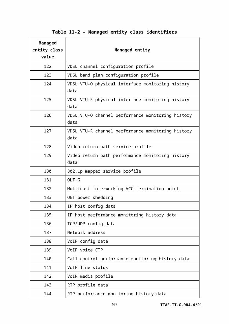
Field Byte 8 7 6 5 4 3 2 1 Comments
Message contents
length
9-10 Size of message contents field,
bytes
Message contents 11 Attribute mask (Note)
(attributes 1-8)
12 Attribute mask (attributes 9-16)
13-n Value of first table row (size
depending on table definition)
…
Value of last table row
NOTE – Exactly one bit of the attribute mask must be set, and that bit must correspond to a read-write
table attribute in the definition of the parent managed entity.
II.3.49 Set table response
Field Byte 8 7 6 5 4 3 2 1 Comments
Transaction correlation
identifier
1-2
Message type 3 0 0 1 DB = 0, AR = 0, AK = 1
bits 5-1: action = set table
Device identifier 4 0 0 0 0 1 0 1 1 Extended OMCI = 0x0B
Managed entity
identifier
5-6 Entity class
7 MS byte entity instance
8 LS byte entity instance
Message contents
length
9-10 Size of message contents
field = 1
TTAE.IT.G.984.4/R1687

Field Byte 8 7 6 5 4 3 2 1 Comments
Message contents 11 0 0 0 0 x x x x Result, reason
0000 command processed
successfully
0001 command processing
error
0010 command not
supported
0011 parameter error
0100 unknown managed
entity
0101 unknown managed
entity instance
0110 device busy
1001 attribute(s) failed or
unknown
Appendix III
Traffic management options
TTAE.IT.G.984.4/R1688

(This appendix does not form an integral part of this Recommendation)
Depending on the trade-off between the complexity and the number of supported features, the ONT can have various traffic management options. Examples of traffic management implementation in the ONT are described in the following clauses. This appendix also indicates how the MIB defined in clause 9 is used for each implementation.
It should be pointed out that the ONT traffic management is not limited to these examples. ONT traffic management is likely a place where every vendor searches for a proprietary feature to give it a competitive advantage. However, every proprietary feature requires some kind of management that impacts the OMCI. In fact, it is difficult for the specification given in this Recommendation to keep up with the technological and feature innovations. It is envisioned that vendor specific managed entities will be needed to manage the traffic management related functions in the ONT.
III.1 Priority queue configuration
When the focus is on low complexity implementation, the ONT uses the priority controlled upstream traffic method. In this case, the ONT has no traffic contract or QoS awareness. The ONT is configured by the OLT with a priority for each connection for both directions.
Theoretically, UPC is needed at every multiplexing point, including the ONT. A system with the UPC function has to monitor the traffic volume entering the network from all active connections to ensure that the agreed parameters are not violated and to deploy a frame discard or tag policy. In the priority queue implementation, the UPC function is moved to the OLT, where it protects the core network. The PON is protected by the "UPC-like" MAC (via the DBA process). The MAC manages all connections from an T-CONT as a whole. Essen-tially, the MAC isolates T-CONTs from each other.
As such, CPEs sharing one T-CONT may have to regulate their own connection streams to maintain quality. A CPE sending out more traffic on one connection will do so at the expense of the other connections established at the same T-CONT.
III.2 Explicit traffic scheduler configuration
In slightly more complex implementations, ONTs may implement some level of traffic scheduling within each T-CONT. These are described using priority queues and one or more levels of traffic scheduler MEs. The arrangement of priority queues and traffic schedulers is determined by the ONT, and is by default not controllable by the OLT. An example of the configuration of the traffic scheduler appears in Figure III.2-1. This model consists of three stages, such as two-delay control and one guaranteed rate control stages. A delay control stage can be worked by HOL (head of line) scheduling. A guaranteed rate control stage can be worked by WRR. This configuration may also be used when the traffic management option attribute in the ONT-G ME is 0 (priority controlled).
TTAE.IT.G.984.4/R1689

Figure III.2-1 – Architectural model in ONT
III.3 Traffic descriptor configuration
An alternative method of controlling traffic in ONTs is to provide traffic descriptors to the ONT, and leave the details of honouring and enforcing these contracts to the ONT implementation. This is controlled using traffic descriptor MEs. This method makes the theoretical assumption that a work-conserving scheduling methodology will be used. In this configuration, traffic is shaped to conform to PIR and PBS in the traffic descriptor ME. This configuration is used when the traffic management option attribute in the ONT-G ME is 1 (rate controlled).
III.4 Priority and rate controlled configuration
Another method of controlling traffic in ONTs is to provide not only priority control with traffic scheduling, but also traffic descriptors. This is controlled using traffic descriptor, priority queue-G and traffic scheduler-G MEs. This method makes the theoretical assumption that a work-conserving scheduling methodology will be used. In this configuration, traffic is policed to conform to PIR and PBS, and may be marked green or yellow according to CIR/CBS/PIR/PBS in the traffic descriptor ME. This configuration is used when the traffic management option attribute in the ONT-G ME is 2 (priority and rate controlled).
TTAE.IT.G.984.4/R1690

III.5 Flexible assignment
By default, priority queues and traffic schedulers are assigned to T-CONTs by the ONT architecture in a fixed configuration, which may not be altered. It is also possible that the ONT implements its QoS components in such a way that they may be flexibly reassigned (Note). ONT flexibility is signalled to the OLT by means of the QoS configuration flexibility bit map attribute of the ONT2-G managed entity.
NOTE – Given the slot-port model of ONT equipment, which appears among other places in the
managed entity identifiers of T-CONT, physical path termination points, the traffic scheduler, and the
related port attribute of the priority queue managed entity, it is not anticipated that implementation
flexibility would extend across slots. Accordingly, OMCI restricts flexibility to be only within a slot,
but does not permit flexible assignment across slots.
Appendix IV
Video return path
TTAE.IT.G.984.4/R1691

ONU TVOLTATM
Video
Tx
(This appendix does not form an integral part of this Recommendation)
IV.1 Network overview
This Recommendation considers networks that use G-PON systems that include a video overlay. This system provides a bidirectional GEM transport service and a unidirectional video or data downstream broadcast or unicast service. If only broadcast video services are desired, then the only video transport required is the third wavelength, as shown in Figure IV.1-1. The ONT converts the signals on the third wavelength to electrical signals on a coaxial output, suitable for video appliances such as televisions.
Figure IV.1-1 – A G-PON with broadcast video only
In many cases, however, interactive video services are needed. In this case, the customer's video termination equipment (commonly referred to as a set-top box, or STB) needs connectivity back to the video control equipment in the central office. In the case of the G-PON system, this connectivity must be provided by the ONT and OLT. This scenario is depicted in Figure IV.1-2. The connection begins in the STB, which transmits its information up the coaxial cables that connect it to the ONT. The ONT must receive this information, and adapt it to be carried on the G-PON in the form of an GEM connection. The OLT terminates the GEM connection, and recovers the VRP upstream datagrams. These datagrams are then interworked at some level (possibly ATM cross-connection, AAL5 interworking, or application-specific interworking). At some point, the resulting data terminates on the video control equipment.
TTAE.IT.G.984.4/R1692

Figure IV.1-2 – A G-PON with interactive video services
Figure IV.1-2 defines two interfaces that are important to interoperability. The STB-ONT interface is the first. This interface is defined by two standards: [SCTE 55-1] and [SCTE 55-2]. These are peer standards that are mutually exclusive; that is, a system will run either one or the other, but not both at one time. Furthermore, each of these standards defines several grades of capability, one being chosen as the default (or basic practice). Clauses IV.2 and IV.4 clarify this interface for the purposes of providing the video return path over G-PON.
The second important interface is the ONT-network interface. This logical interface is a GEM connection that conducts the return path information back to the video equipment in the central office. The information must be formatted in a standardized way so that common control equipment can be used. The formatting depends on the particular return path interface being used. Clauses IV.3 and IV.5 define these formats.
Given the situation that there are two modes on both interfaces, it makes sense that the ONT has two modes of operation, denoted mode 1 and mode 2. Mode 1 corresponds to support of the SCTE 55-1 system, and mode 2 corresponds to support of the SCTE 55-2 systems. The mode is set by the network operator during the initialization management of the video service.
IV.2 Mode 1 STB-ONT interface
The STB-ONT interface, in this case, is based on that from the commonly deployed [SCTE 55-1]. [SCTE 55-1] defines all the aspects of the interactive video control system, while the STB-ONT interface herein described is only concerned with the upstream transmission of data. Therefore, we specify below which clauses are relevant to the definition of the STB-ONT interface.
Relevant clauses of [SCTE 55-1] that apply to the STB-ONT interface:
5.2 Physical layer for return-path transmission
5.2.1 Return-path modem description – A general explanation, required.
5.2.2 RF return path packet format – Specifies the format of the upstream packet, required.
TTAE.IT.G.984.4/R1693

Please note that the unique word specified in this clause is given in standard QPSK notation, and not differential QPSK notation.
5.2.3 RF return-path forward error correction – Specifies the code used for the FEC bytes, optional.
Please note that while the FEC will be calculated by compliant STBs, the ONT's processing of the FEC is optional.
5.2.4 RF return-path randomizer – Specifies the randomizer used in the upstream packets, required.
Please note that the randomizer output is applied to the entire packet EXCEPT the unique word. Also, the programmable value of the randomizer seed to be used is given in the video return path service profile managed entity.
5.2.5 RF return path modulator – Specifies the physical layer to be used, required.
Note that while the centre frequency is specified to a wider range, in actual practice this frequency is limited from 8 to 12 MHz. Also, the DQPSK mode to be used is given in the video return path service profile managed entity.
5.2.6 RF return-path demodulator specification – Specifies the physical layer to be used, required.
All other clauses of [SCTE 55-1] are not relevant to the STB-ONT interface. In particular, the extended practice (clause 5.3) is explicitly not supported.
IV.3 Mode 1 ONT-network interface
In mode 1, the ONT must forward the derandomized packet sequence field (1 byte) and the ATM data (53 bytes) intact to the video control system. The procedure to do this is:
1) Receive the DQPSK burst, and capture all 62 bytes of data and measure the power level of the burst relative to the nominal input power level for the receiver.
2) Exclusive OR the randomizer sequence with the received data.
3) Calculate the FEC parity, compare with that received, and detect/correct errors. Discard cells that have uncorrectable errors (optional).
4) Assemble the datagram to be forwarded, which is 56 bytes in length.
5) Encapsulate the datagram using GEM.
6) Forward the GEM fragment over a GEM port CTP allocated on the PON.
The structure of the incoming RF burst data and the outgoing GEM circuit data is shown in Figure IV.3-1. The outgoing datagram is always 56 bytes in length, and is composed of a two-byte level indication field, a one-byte packet sequence field, and a 53-byte ATM data field. The unique word and FEC bytes are terminated in the ONT. The resulting GEM fragment is 61 bytes (488 bits).
TTAE.IT.G.984.4/R1694

Figure IV.3-1– The transformation of a 55-1 formatted burst into a GEM fragment
The level indication field is formatted as: a1bb bbbb 0000 0000, where:
Bit a is a detection indicator to be used if FEC is implemented in the ONT (if not, bit a should be set to zero), where:
a = 0 means burst was detected without errors;
a = 1 means a burst was detected with errors, but was corrected.
The 1 is a reserved bit.
Bits bbbbbb are a power indication, containing the 2s complement representation of the measured power of this burst, in units of decibels relative to the nominal receive power of the equipment. For example, if the nominal receive power of the ONT is 10 dBmV, and a burst arrives with 17 dBmV, then bbbbbb = 000111. If the same ONT receives a 7 dBmV burst, then bbbbbb = 111101.
The "0000 0000" are all reserved bits.
The GEM port-ID that carries the video return path data can be configured to provide a non-assured traffic service. The data rate of the service can be calculated from the latency requirements of the 55-1 protocol and equipment implementation. Practical implementations of this protocol have round trip delay tolerances on the order of 100 ms. After this time, the STB will begin to re-transmit its upstream bursts. One of the contributors of the delay will be the cell transmission time, which in our case is the inverse of the data burst rate.
For example, if 20 ms is allocated for cell transmission time, then the cell rate for the video return path connection should be made 488/20ms ~ 25 kbit/s.
To summarize, the ONT-network interface is 56-byte payloads (as defined above) encapsulated in GEM, carried in a GEM port-ID.
TTAE.IT.G.984.4/R1695

IV.4 Mode 2 STB-ONT interface
The STB-ONT interface in this case is based on that from the commonly deployed [SCTE 55-2]. [SCTE 55-2] defines all the aspects of the interactive video control system, while the STB-ONT interface herein described is only concerned with the upstream transmission of data. Therefore, we specify below which clauses are relevant to the definition of the STB-ONT interface.
Relevant clauses of [SCTE 55-2] that apply to the STB-ONT interface:
2.2 Upstream physical interface specification – A general explanation of the system, required.
2.2.1 Quaternary phase shift keying (QPSK) – A description of the physical layer used, required.
– Grade A 256 kbit/s is optional.
– Grade B 1.544 Mbit/s is required.
– Grade C 3.088 Mbit/s is optional.
2.2.2 Coaxial cable impedance – A physical layer parameter, required.
2.2.3 Time division multiple access (TDMA), optional.
2.2.4 Contention-based access, required.
All other clauses of [SCTE 55-2] are not relevant to the STB-ONT interface.
IV.5 Mode 2 ONT-network interface
In mode 2, the ONT forwards the de-randomized ATM cells (53 bytes) to the video control system. The procedure to do this is:
1) Receive the QPSK burst, and capture all 59 bytes of data.
2) Exclusive OR the randomizer sequence with the received data.
3) Calculate the FEC parity, compare with that received, and detect/correct errors. Discard cells that have uncorrectable errors (required).
4) Forward the ATM cells over a GEM port-ID allocated on the PON.
The structure of the incoming RF burst data and the outgoing GEM data is shown in Figure IV.5-1. The outgoing datagram is a 53-byte ATM cell. The unique word and FEC bytes are terminated in the ONT. The resulting GEM fragment is 58 bytes (464 bits).
TTAE.IT.G.984.4/R1696

Figure IV.5-1 – The transformation of a 55-2 formatted burst into a GEM fragment
The GEM port-ID that carries the video return path data can be configured to support the operator-chosen QoS.
To summarize, the ONT-network interface is 53-byte payloads (as defined above) encapsulated in GEM, carried in a GEM port-ID.
Entity class.
NOTE – This message format pertains to ANI-G, RE ANI-G, PPTP RE UNI, RE upstream amplifier or RE downstream amplifier entity class.
TTAE.IT.G.984.4/R1697

Bibliography
[b-ITU-T G.984.1] Recommendation ITU-T G.984.1 (2008), Gigabit-capable passive optical networks (GPON): General characteristics.
[b-ITU-T G.992.2] Recommendation ITU-T G.992.2 (1999), Splitterless asymmetric digital subscriber line (ADSL) transceivers.
[b-ITU-T X.690] Recommendation ITU-T X.690 (2008) | ISO/IEC 8825-1:2008, Information technology – ASN.1 encoding rules: Specification of Basic Encoding Rules (BER), Canonical Encoding Rules (CER) and Distinguished Encoding Rules (DER).
[b-ITU-T Y.1731] Recommendation ITU-T Y.1731 (2008), OAM functions and mechanisms for Ethernet based networks.
[b-ATIS T1.403] ATIS T1.403 (2007), Network to Customer Installation Interfaces - DS1 Electrical Interface.<http://webstore.ansi.org/RecordDetail.aspx?sku=T1.403-1999(R2007)>
[b-IEEE 802.1AB] IEEE 802.1AB-2005, IEEE Standard for local and metropolitan area networks Station and Media Access Control Connectivity Discovery.<http://standards.ieee.org/getieee802/download/802.1AB-2005.pdf>
[b-IEEE 802.1ag] IEEE 802.1ag-2007, IEEE Standard for local and metropolitan area networks Virtual Bridged Local Area Networks Amendment 5: Connectivity Fault Management.<http://standards.ieee.org/getieee802/download/802.1ag-2007.pdf>
[b-IEEE 802.1X] IEEE 802.1X-2004, IEEE Standard for local and metropolitan area networks Port-Based Network Access Control.<http://standards.ieee.org/getieee802/download/802.1X-2004.pdf>
[b-IEEE 802.3] IEEE 802.3-2005, IEEE Standard for local and metropolitan area networks Specific requirements Part 3: Carrier Sense Multiple Access with Collision Detection (CSMA/CD) Access Method and Physical Layer Specifications.<http://standards.ieee.org/getieee802/802.3.html>
[b-IETF RFC 1213] IETF RFC 1213 (1991), Management Information Base for Network Management of TCP/IP-based internets: MIB-II.<http://www.ietf.org/rfc/rfc1213.txt>
[b-IETF RFC 1700] IETF RFC 1700 (1994), Assigned Numbers.<http://www.ietf.org/rfc/rfc1700.txt>
TTAE.IT.G.984.4/R1698

[b-IETF RFC 2236] IETF RFC 2236 (1997), Internet Group Management Protocol, Version 2.<http://www.ietf.org/rfc/rfc2236.txt>
[b-IETF RFC 2464] IETF RFC 2464 (1998), Transmission of IPv6 Packets over Ethernet Networks.<http://www.ietf.org/rfc/rfc2464.txt>
[b-IETF RFC 2516] IETF RFC 2516 (1999), A Method for Transmitting PPP over Ethernet (PPPoE).<http://www.ietf.org/rfc/rfc2516.txt>
[b-IETF RFC 2579] IETF RFC 2579 (1999), Textual Conventions for SMIv2.<http://www.ietf.org/rfc/rfc2579.txt>
[b-IETF RFC 2685] IETF RFC 2685 (1999), Virtual Private Networks Identifier.<http://www.ietf.org/rfc/rfc2685.txt>
[b-IETF RFC 2737] IETF RFC 2737 (1999), Entity MIB (Version 2).<http://www.ietf.org/rfc/rfc2737.txt>
[b-IETF RFC 2819] IETF RFC 2819 (2000), Remote Network Monitoring Management Information Base.<http://www.ietf.org/rfc/rfc2819.txt>
[b-IETF RFC 2863] IETF RFC 2863 (2000), The Interfaces Group MIB.<http://www.ietf.org/rfc/rfc2863.txt>
[b-IETF RFC 2933] IETF RFC 2933 (2000), Internet Group Management Protocol MIB.<http://www.ietf.org/rfc/rfc2933.txt>
[b-IETF RFC 3261] IETF RFC 3261 (2002), SIP: Session Initiation Protocol.<http://www.ietf.org/rfc/rfc3261.txt>
[b-IETF RFC 3376] IETF RFC 3376 (2002), Internet Group Management Protocol, Version 3.<http://www.ietf.org/rfc/rfc3376.txt>
[b-IETF RFC 3417] IETF RFC 3417 (2002), Transport Mappings for the Simple Network Management Protocol (SNMP).<http://www.ietf.org/rfc/rfc3417.txt>
[b-IETF RFC 3810] IETF RFC 3810 (2004), Multicast Listener Discovery Version 2 (MLDv2) for IPv6.<http://www.ietf.org/rfc/rfc3810.txt>
[b-IETF RFC 4541] IETF RFC 4541 (2006), Considerations for Internet Group Management Protocol (IGMP) and Multicast Listener Discovery
TTAE.IT.G.984.4/R1699

(MLD) Snooping Switches.<http://www.ietf.org/rfc/rfc4541.txt>
[b-IETF RFC 4789] IETF RFC 4789 (2006), Simple Network Management Protocol (SNMP) over IEEE 802 Networks.<http://www.ietf.org/rfc/rfc4789.txt>
[b-Floyd] Floyd, S, and Jacobson, V (1993), Random early detection gateways for congestion avoidance. IEEE/ACM Transactions on Networking, V.1 N.4, August, pp. 397-413.
[b-ATIS 0300231] ATIS 0300231-2003, Layer 1 In-Service Digital Transmission Performance Monitoring.
[b-IETF RFC 2597] IETF RFC 2597 (1999), Assured Forwarding PHB Group.
[b-IETF RFC 2698] IETF RFC 2698 (1999), A Two Rate Three Color Marker.
[b-IETF RFC 3926] IETF RFC 3926 (2004), FLUTE – File Delivery Over Unidirectional Transport.
[b-IETF RFC 4115] IETF RFC 4115 (2005), A Differentiated Service Two-Rate, Three-Color Marker With Efficient Handling Of In-Profile Traffic.
[b-ISO/IEC 9798-4] ISO/IEC 9798-4:1999, Information technology – Security techniques – Entity authentication – Part 4: Mechanisms using a cryptographic check function.
[b-G.Imp984.4] ITU-T G.984.4, Implementer's Guide, Second revision.
Index
TTAE.IT.G.984.4/R1700

ME name Clause Class
802.11 general purpose object 9.6.4 94
802.11 MAC and PHY operation and antenna data 9.6.5 95
802.11 performance monitoring history data 9.6.7 96
802.11 PHY FHSS DSSS IR tables 9.6.6 97
802.11 station management data 1 9.6.2 92
802.11 station management data 2 9.6.3 93
802.1p mapper service profile 9.3.10 130
AAL 5 performance monitoring history data 9.13.6 18
AAL 5 profile 9.13.5 16
ANI-G 9.2.1 263
ARP configuration data 9.4.11 77
ARP service profile 9.4.10 76
Attribute 9.12.10 289
Authentication security method 9.12.4 148
Call control performance monitoring history data 9.9.12 140
Cardholder 9.1.5 5
CES physical interface performance monitoring history data 9.8.4 23
CES service profile-G 9.8.3 21
Circuit pack 9.1.6 6
Dot1 rate limiter 9.3.18 298
Dot1ag CFM stack 9.3.25 305
Dot1ag chassis-management info 9.3.26 306
Dot1ag default MD level 9.3.21 301
Dot1ag maintenance association 9.3.20 300
Dot1ag maintenance domain 9.3.19 299
Dot1ag MEP 9.3.22 302
Dot1ag MEP CCM database 9.3.24 304
Dot1ag MEP status 9.3.23 303
Dot1X configuration profile 9.3.15 291
Dot1X performance monitoring history data 9.3.16 292
Dot1X port extension package 9.3.14 290
Equipment extension package 9.1.9 160
Equipment protection profile 9.1.11 159
Ethernet flow termination point 9.8.9 286
Ethernet performance monitoring history data 9.5.2 24
TTAE.IT.G.984.4/R1701

ME name Clause Class
Ethernet performance monitoring history data 2 9.5.3 89
Ethernet performance monitoring history data 3 9.5.4 296
Extended VLAN tagging operation configuration data 9.3.13 171
FEC performance monitoring history data 9.2.11 312
GAL Ethernet performance monitoring history data 9.2.8 276
GAL Ethernet profile 9.2.7 272
GAL TDM performance monitoring history data 9.2.10 275
GAL TDM profile 9.2.9 271
GEM interworking termination point 9.2.4 266
GEM port network CTP 9.2.3 268
GEM port performance monitoring history data 9.2.6 267
GEM traffic descriptor 9.11.3 280
General purpose buffer 9.12.12 308
ICMP performance monitoring history data 1 9.4.8 72
ICMP performance monitoring history data 2 9.4.9 73
Interworking VCC termination point 9.13.4 14
IP host config data 9.4.12 134
IP host performance monitoring history data 9.4.13 135
IP port configuration data 9.4.3 67
IP route table 9.4.4 74
IP router configuration data 9.4.2 69
IP router performance monitoring history data 1 9.4.6 70
IP router performance monitoring history data 2 9.4.7 71
IP router service profile 9.4.1 68
IP static routes 9.4.5 75
Large string 9.12.5 157
Logical N x 64 kbit/s sub-port connection termination point 9.8.2 13
MAC bridge configuration data 9.3.2 46
MAC bridge performance monitoring history data 9.3.3 51
MAC bridge port bridge table data 9.3.8 50
MAC bridge port configuration data 9.3.4 47
MAC bridge port designation data 9.3.5 48
MAC bridge port filter preassign table 9.3.7 79
MAC bridge port filter table data 9.3.6 49
MAC bridge port performance monitoring history data 9.3.9 52
MAC bridge service profile 9.3.1 45
Managed entity 9.12.9 288
TTAE.IT.G.984.4/R1702

ME name Clause Class
MGC config data 9.9.16 155
MGC config portal 9.9.20 154
MGC performance monitoring history data 9.9.17 156
MoCA Ethernet performance monitoring history data 9.10.2 163
MoCA interface performance monitoring history data 9.10.3 164
Multicast GEM interworking termination point 9.2.5 281
Multicast operations profile 9.3.27 309
Multicast subscriber config info 9.3.28 310
Multicast subscriber monitor 9.3.29 311
Network address 9.12.3 137
Network dial plan table 9.9.10 145
Octet string 9.12.11 307
OLT-G 9.12.2 131
OMCI 9.12.8 287
ONT data 9.1.3 2
ONT power shedding 9.1.7 133
ONT remote debug 9.1.12 158
ONT2-G 9.1.2 257
ONT-G 9.1.1 256
Physical path termination point 802.11 UNI 9.6.1 91
Physical path termination point CES UNI 9.8.1 12
Physical path termination point Ethernet UNI 9.5.1 11
Physical path termination point ISDN UNI 9.9.21 80
Physical path termination point LCT UNI 9.13.3 83
Physical path termination point MoCA UNI 9.10.1 162
Physical path termination point POTS UNI 9.9.1 53
Physical path termination point video ANI 9.13.2 90
Physical path termination point video UNI 9.13.1 82
Physical path termination point xDSL UNI part 1 9.7.1 98
Physical path termination point xDSL UNI part 2 9.7.2 99
Port mapping package-G 9.1.8 297
Priority queue-G 9.11.1 277
Protection data 9.1.10 279
Pseudowire maintenance profile 9.8.7 284
Pseudowire performance monitoring history data 9.8.8 285
Pseudowire termination point 9.8.5 282
Radius performance monitoring history data 9.3.17 293
TTAE.IT.G.984.4/R1703

ME name Clause Class
RTP performance monitoring history data 9.9.13 144
RTP profile data 9.9.7 143
RTP pseudowire parameters 9.8.6 283
SIP agent config data 9.9.3 150
SIP agent performance monitoring history data 9.9.14 151
SIP call initiation performance monitoring history data 9.9.15 152
SIP config portal 9.9.19 149
SIP user data 9.9.2 153
Software image 9.1.4 7
TC adaptor performance monitoring history data xDSL 9.7.25 116
T-CONT 9.2.2 262
TCP/UDP config data 9.4.14 136
Threshold data 1 9.12.6 273
Threshold data 2 9.12.7 274
Traffic scheduler-G 9.11.2 278
TU CTP 9.8.10 294
TU performance monitoring history data 9.8.11 295
UNI-G 9.12.1 264
VDSL2 line configuration extensions 9.7.6 165
VDSL2 line inventory and status data part 1 9.7.16 168
VDSL2 line inventory and status data part 2 9.7.17 169
VDSL2 line inventory and status data part 3 9.7.18 170
Video return path performance monitoring history data 9.13.8 129
Video return path service profile 9.13.7 128
VLAN tagging filter data 9.3.11 84
VLAN tagging operation configuration data 9.3.12 78
Voice service profile 9.9.6 58
VoIP application service profile 9.9.8 146
VoIP config data 9.9.18 138
VoIP feature access codes 9.9.9 147
VoIP line status 9.9.11 141
VoIP media profile 9.9.5 142
VoIP voice CTP 9.9.4 139
VP network CTP-G 9.13.9 269
VP performance monitoring history data 9.13.10 62
xDSL channel configuration profile 9.7.7 107
xDSL channel downstream status data 9.7.19 102
TTAE.IT.G.984.4/R1704

ME name Clause Class
xDSL channel upstream status data 9.7.20 103
xDSL downstream RFI bands profile 9.7.11 111
xDSL line configuration profile part 1 9.7.3 104
xDSL line configuration profile part 2 9.7.4 105
xDSL line configuration profile part 3 9.7.5 106
xDSL line inventory and status data part 1 9.7.12 100
xDSL line inventory and status data part 2 9.7.13 101
xDSL line inventory and status data part 3 9.7.14 166
xDSL line inventory and status data part 4 9.7.15 167
xDSL PSD mask profile 9.7.10 110
xDSL subcarrier masking downstream profile 9.7.8 108
xDSL subcarrier masking upstream profile 9.7.9 109
xDSL xTU-C channel performance monitoring history data 9.7.23 114
xDSL xTU-C performance monitoring history data 9.7.21 112
xDSL xTU-R channel performance monitoring history data 9.7.24 115
xDSL xTU-R performance monitoring history data 9.7.22 113
TTAE.IT.G.984.4/R1705

영문단체표준 해설서
1. 범위
1 장에서는 본 표준의 범위를 기술한다.
2. 참고
2 장에서는 본 표준의 참고 표준을 기술한다.
3. 정의
3 장에서는 본 표준에 대한 용어의 정의를 기술한다.
4. 약어
4 장에서는 본 표준의 약어를 기술한다.
5. 개념
5 장에서는 본 표준에 기술한 문서에 대한 개념을 기술한다.
6. 기준 모델과 상호관계
6 장에서는 PON 망의 기준 모델을 정의하고 각 블록 별 기능에 대해 기술한다.
7. 관리 인터페이스 규격 요구조건
7 장에서는 OMCI 를 통한 관리 인터페이스 규격인 형상, 장애, 성능, 보안 등의 관리에
대한 요구 조건을 기술한다.
8. OMCI 용 프로토콜 비 종속 MIB
8 장에서는 OMCI 관리 객체에 대한 정의를 기술한다.
9. MIB 설명
8 장에서는 전송 수렴 부 계층에서 허용하는 OLT 와 ONT 사이의 최대 논리적 거리에 대해
기술한다.
TTAE.IT.G.984.4/R1706

10. ONT 관리 및 제어 채널(OMCC)
10 장에서는 ONT 관리 및 제어 채널에 대해 기술한다.
11. ONT 관리 및 제어 프로토콜
11 장에서는 ONT 관리 및 제어 프로토콜, 패킷 포맷에 대해 기술한다.
부록 I. OMCI 공통 메커니즘과 서비스
부록 I 에서는 OMCI 공통메커니즘과 서비스에 대해 기술한다.
부록 II. OMCI 메시지 모음
부록 II 에서는 OMCI 메시지를 요약한 모음에 대해 기술한다.
부록 III. 트래픽 관리 옵션
부록 III 에서는 OMCI 를 이용한 트래픽 관리 옵션에 대해 기술한다.
부록 IV. 비디오 회귀 경로
부록 IV 에서는 비디오의 상호 연결을 통한 비디오 서비스 경로에 대해 기술한다.
부록 V.
부록 V 에서는 IEEE 1588 을 이용한 동기화 설정 시간과 주파수에 관한 내용에 대해
기술한다.
부록 VI.
부록 VI 에서는 이더넷 표준에서 사용되는 동기식 이더넷을 GPON 에 사용하기 위한
방법에 대해 기술한다.
표준작성 공헌자
TTAE.IT.G.984.4/R1707
표준 번호: TTAE.IT-G.984.4/R1
이 표준의 제․개정 및 발간을 위해 아래와 같이 여러분들이 공헌하였습니다.
구분 성명 위원회 및 직위 연락처 소속사
표준(과제) 제안 김광옥 광 전송 프로젝트
그룹 위원
kr
한국전자통신연구원
PG201
표준 초안
작성자
김광옥광 전송 프로젝트
그룹 위원
042-860-1686
한국전자통신연구원
PG201
이상수광 전송 프로젝트
그룹 위원
042-860-6186
한국전자통신연구원
PG201
표준 초안 검토김성운
광 전송 프로젝트 그룹
(PG201) 의장[email protected]
r부경
대학교
외 프로젝트그룹 위원
표준안 심의
사무국 담당
TTAE.IT.G.984.4/R1708

( 뒷 표지)
정보통신단체표준(영문표준)
기가비트 수동 광통신망(GPON):ONT 관리 및 제어 인터페이스 규격
Gigabit-capable passive optical networks (GPON): ONT management and control interface specification
발행인 : 한국정보통신기술협회 회장
발행처 : 한국정보통신기술협회
463-824, 경기도 성남시 분당구 서현동 267-2Tel : 031-724-0114, Fax : 031-724-0019
발행일 : 2014.xx
TTAE.IT.G.984.4/R11