Disclaimer - Seoul National...
145
저작자표시-비영리-변경금지 2.0 대한민국 이용자는 아래의 조건을 따르는 경우에 한하여 자유롭게 l 이 저작물을 복제, 배포, 전송, 전시, 공연 및 방송할 수 있습니다. 다음과 같은 조건을 따라야 합니다: l 귀하는, 이 저작물의 재이용이나 배포의 경우, 이 저작물에 적용된 이용허락조건 을 명확하게 나타내어야 합니다. l 저작권자로부터 별도의 허가를 받으면 이러한 조건들은 적용되지 않습니다. 저작권법에 따른 이용자의 권리는 위의 내용에 의하여 영향을 받지 않습니다. 이것은 이용허락규약 ( Legal Code) 을 이해하기 쉽게 요약한 것입니다. Disclaimer 저작자표시. 귀하는 원저작자를 표시하여야 합니다. 비영리. 귀하는 이 저작물을 영리 목적으로 이용할 수 없습니다. 변경금지. 귀하는 이 저작물을 개작, 변형 또는 가공할 수 없습니다.
Transcript of Disclaimer - Seoul National...
저 시-비 리- 경 지 2.0 한민
는 아래 조건 르는 경 에 한하여 게
l 저 물 복제, 포, 전송, 전시, 공연 송할 수 습니다.
다 과 같 조건 라야 합니다:
l 하는, 저 물 나 포 경 , 저 물에 적 된 허락조건 명확하게 나타내어야 합니다.
l 저 터 허가를 면 러한 조건들 적 되지 않습니다.
저 에 른 리는 내 에 하여 향 지 않습니다.
것 허락규약(Legal Code) 해하 쉽게 약한 것 니다.
Disclaimer
저 시. 하는 원저 를 시하여야 합니다.
비 리. 하는 저 물 리 목적 할 수 없습니다.
경 지. 하는 저 물 개 , 형 또는 가공할 수 없습니다.

Ph.D. DISSERTATION
A Miniaturized, Eye-conformable, and Long-
term Reliable Retinal Prosthesis using
Monolithic Fabrication of Liquid Crystal
Polymer (LCP)
액정폴리머를 기반의 소형, 안구밀착형, 장기안정적인 인공망막장치
By
JOONSOO JEONG
AUGUST 2015
DEPARTMENT OF ELECTRICAL ENGINEERING AND
COMPUTER SCIENCE
COLLEGE OF ENGINEERING
SEOUL NATIONAL UNIVERSITY

A Miniaturized, Eye-conformable, and Long-
term Reliable Retinal Prosthesis using
Monolithic Fabrication of Liquid Crystal
Polymer (LCP)
액정폴리머를 기반의 소형, 안구밀착형, 장기안정적인 인공망막장치
지도교수 김 성 준
이 논문을 공학박사 학위논문으로 제출함
2015년 5월
서울대학교 대학원
전기∙컴퓨터공학부
정 준 수
정준수의 공학박사 학위논문을 인준함
2015년 5월
위 원 장 (인)
부위원장 (인)
위 원 (인)
위 원 (인)
위 원 (인)

i
ABSTRACT
A Miniaturized, Eye-conformable, and
Long-term Reliable Retinal Prosthesis
using Monolithic Fabrication of Liquid
Crystal Polymer (LCP)
Joonsoo Jeong
School of Electrical Engineering and Computer Science
The Graduate School
Seoul National University
A novel retinal prosthetic device was developed using liquid crystal polymer (LCP) to
address the problems associated with conventional metal- and polymer-based devices: the
hermetic metal package is bulky, heavy and labor-intensive, whereas a thin, flexible and
MEMS-compatible polymer-based system is not durable enough for chronic implantation.
Exploiting the advantageous properties of LCP such as a low moisture absorption rate,
thermo-bonding and thermo-forming, a small, light-weight, long-term reliable retinal
prosthesis was fabricated that can be conformally attached on the eye-surface. A LCP

ii
fabrication process using monolithic integration and conformal deformation was
established enabling miniaturization and a batch manufacturing process as well as
eliminating the need for feed-through technology. The fabricated 16-channels LCP-based
retinal implant had 14 mm-diameter with the maximum thickness of 1.4 mm and weight
of 0.4 g and could be operated wirelessly up to 16 mm of distance in the air.
The long-term reliability of the all-LCP retinal device was evaluated in vitro as well as in
vivo. Because an all-polymer implant introduces intrinsic gas permeation for which the
traditional helium leak test for metallic packages was not designed to quantify, a new set
of reliability tests were designed and carried out specifically for all-polymer implants.
Moisture ingress through various pathways were classified into polymer surface,
polymer-polymer and polymer-metal adhesions each of which were quantitatively
investigated by analytic calculation, in vitro aging test of electrode part and package part,
respectively. The functionality and long-term implantation stability of the device was
verified through in vivo animal experiments by measuring the cortical potential and
monitoring implanted dummy devices for more than a year, respectively. Samples of the
LCP electrodes array failed after 114 days in 87°C salin as a result of water penetration
through the LCP-metal interface. An eye-confirmable LCP package survived more than
35 days in an accelerated condition at 87°C. The in vivo results confirmed that no adverse
effects around the retina were observed after implantation of the device for more than a
year.

iii
Keywords : retinal prosthesis, liquid crystal polymer, neural prosthesis, conformable,
monolithic integration
Student Number : 2011-30256

iv
Contents
ABSTRACT ............................................................................ i
Contents .................................................................................iv
List of Figures .......................................................................xi
List of Tables .......................................................................xxi
Chapter 1 : Introduction ....................................................... 1
1.1. Neuroprosthetic devices ..................................................... 1
1.2. Retinal prosthesis ............................................................... 2
1.2.1. Concept .............................................................................................. 2
1.2.2. Three approaches ............................................................................... 3
1.2.3. Camera vs. Photodiode ...................................................................... 4
1.3. Conventional devices ......................................................... 5

v
1.4. Liquid Crystal Polymer (LCP) ........................................... 7
1.4.1. Low moisture absorption and permeability ...................................... 9
1.4.2. Thermoplastic property ..................................................................... 9
1.4.3. Compatibility with MEMS technologies ........................................ 10
1.4.4. RF characteristics ............................................................................ 10
1.5. LCP-based retinal prosthesis ............................................ 11
1.6. Long-term reliability ........................................................ 12
1.7. Dissertation outline .......................................................... 14
Chapter 2: Methods ............................................................. 16
2.1. System Overview ............................................................. 16
2.2. Microfabrication on LCP ................................................. 18
2.2.1. Limitations of the previous microfabrication technique on LCP .... 19
2.2.2. Improved LCP-based microfabrication ........................................... 22
2.2.2.1. Electroplated micro-patterning .................................................... 23
2.2.2.2. Laser-thinning for higher flexibility ............................................ 24
2.2.2.3. Laser-ablation for site opening .................................................... 25

vi
2.3. All-LCP Monolithic Fabrication ...................................... 26
2.3.1. Multilayered integration .................................................................. 29
2.3.1.1. Electrical components .................................................................. 29
2.3.1.2. Thermal lamination ...................................................................... 32
2.3.1.3. Layer configuration ..................................................................... 34
2.3.2. Thermal deformation ....................................................................... 35
2.3.2.1. Deformation process .................................................................... 35
2.3.2.2. Wavy lines for stretchability ........................................................ 36
2.3.2.3. Electrical properties of the deformed coil .................................... 40
2.3.3. Circuit Assembly ............................................................................. 40
2.3.3.1. Stimulation ASIC ......................................................................... 40
2.3.3.2. Surrounding circuitries ................................................................ 41
2.3.4. Packaging ......................................................................................... 43
2.3.5. Laser Machining .............................................................................. 44
2.4. Device characterization .................................................... 44
2.4.1. Transmitter Circuit and Wireless Operation .................................... 45
2.4.1.1. Transmitter circuit ........................................................................ 45

vii
2.4.1.2. Transmitter coil ............................................................................ 46
2.4.1.3. Wireless operation test ................................................................. 46
2.4.2. Electrochemical measurements ........................................................ 48
2.5. Long-term reliability tests in vitro ................................... 49
2.5.1. Failure mechanisms of an all-LCP device ....................................... 49
2.5.2. Analytic calculation ......................................................................... 51
2.5.3. Long-term reliability tests in accelerated environment ................... 55
2.5.3.1. Long-term reliability of electrode array ....................................... 55
2.5.3.2. Long-term reliability of package ................................................. 57
2.5.3.3. Long-term reliability of complete device .................................... 58
2.5.4. Long-term electrochemical stability ................................................ 59
2.6. Acute and Chronic Evaluation in vivo ............................. 60
2.6.1. Surgical implantation ....................................................................... 60
2.6.2. Acute functionality test .................................................................... 62
2.6.3. Long-term implantation stability ..................................................... 63

viii
Chapter 3: Results ............................................................... 64
3.1. Microfabrication on LCP ................................................. 64
3.1.1. Electroplated micro-patterning ........................................................ 64
3.1.2. Laser-ablation for site opening ........................................................ 67
3.1.3. Laser-thinning for higher flexibility ................................................ 69
3.2. All-LCP Monolithic fabrication ....................................... 71
3.2.1. Multilayered integration .................................................................. 71
3.2.2. Thermal deformation ....................................................................... 73
3.2.2.1. Deformation results ..................................................................... 73
3.2.2.2. Wavy lines for stretchability ........................................................ 74
3.2.2.3. Effect on the electrical properties ................................................ 74
3.2.3. Circuit assembly .............................................................................. 76
3.2.4. Packaging ......................................................................................... 77
3.2.5. Laser machining ............................................................................... 79
3.3. Device Characterization ................................................... 80
3.3.1. General specifications ...................................................................... 81

ix
3.3.2. Transmitter circuit and coil .............................................................. 83
3.3.3. Wireless operation ........................................................................... 83
3.3.4. Electrochemical measurements ........................................................ 84
3.4. Long-term reliability tests in vitro ................................... 86
3.4.1. Analytic calculation ......................................................................... 87
3.4.2. Long-term reliability tests in accelerated condition ........................ 90
3.4.2.1. Long-term reliability of electrode arrays ..................................... 90
3.4.2.2. Long-term reliability of package ................................................. 92
3.4.2.3. Long-term reliability of complete device .................................... 93
3.4.3. Long-term Electrochemical stability ............................................... 93
3.5. Acute and chronic evaluation in vivo ............................... 95
3.5.1. Surgical implantation ....................................................................... 95
3.5.2. Acute functionality test .................................................................... 96
3.5.3. Long-term implantation stability ..................................................... 97

x
Chapter 4: Discussion ........................................................ 100
4.1. Comparison with conventional devices ......................... 100
4.2. Potential applications ..................................................... 102
4.3. Opportunities for further improvements ........................ 102
4.4. Long-term reliability ...................................................... 104
Chapter 5: Conclusion ...................................................... 108
Reference ............................................................................ 110
국문초록 .............................................................................. 118
감사의 글 ............................................................................ 121

xi
List of Figures
FIGURE 1-1 THREE APPROACHES OF RETINAL IMPLANT DEPENDING ON WHERE IN THE RETINA THE
ELECTRODE IS INSERTED: EPIRETINAL, SUBRETINAL AND SUPRACHOROIDAL APPROACHES. ............... 4
FIGURE 1-2 COMMERCIALLY AVAILABLE LCP FILM (VECSTAR, KURARAY) AND MOLECULAR STRUCTURE 8
FIGURE 2-1 OVERALL CONFIGURATION OF LCP-BASED RETINAL PROSTHESIS: A CAMERA ON THE
GLASSES, EXTERNAL UNIT INDUCTIVELY LINKED TO THE IMPLANTED UNIT FOR POWER AND DATA
TRANSMISSION. IMPLANTED UNIT IS MONOLITHICALLY FABRICATED FROM LCP. ............................. 17
FIGURE 2-2 SCHEMATIC DIAGRAM OF THE EXTERNAL AND INTERNAL UNIT OF RETINAL PROSTHETIC
SYSTEM; THE EXTERNAL UNIT IS IMPLEMENTED ON PCB WITH A WIRE-WOUND COIL, WHILE THE
IMPLANTED UNIT IS FABRICATED BY LCP MONOLITHIC INTEGRATION. ............................................... 18
FIGURE 2-3 PREVIOUS PROCESS FOR MICROFABRICATION ON LCP FILM .................................................... 19
FIGURE 2-4 PROBLEMS ASSOCIATED WITH THE PREVIOUS METHOD LAMINATING A COVER LAYER WITH
PRE-DRILLED HOLES: MISALIGNMENT AND COVER LAYER REFLOW. ..................................................... 21
FIGURE 2-5 IMPROVED MICROFABRICATION PROCESS ON LCP .................................................................... 23
FIGURE 2-6 BENDING FORCE MEASUREMENT FOR COMPARING THE FLEXIBILITY BEFORE AND AFTER THE

xii
LASER-THINNING PROCESS ........................................................................................................................ 25
FIGURE 2-7 THE RETINAL PROSTHETIC DEVICE CONSISTS OF MAINLY THREE FUNCTIONAL BLOCKS: 1) A
COIL FOR WIRELESS RECEPTION OF POWER AND DATA, 2) CIRCUIT FOR GENERATING 16-CHANNEL
STIMULATION PULSES AND 3) 16-CHANNEL RETINAL ELECTRODE ARRAY ......................................... 27
FIGURE 2-8 MONOLITHIC FABRICATION PROCESS OF LCP-BASED RETINAL PROSTHESIS: (A)
INDEPENDENT FILM FABRICATION AND THERMAL LAMINATION TO FORM A MULTILAYERED
SUBSTRATE, (B) THERMAL DEFORMATION USING A METAL JIG PAIR FOR EYE-CONFORMABLE
CURVATURE, (C) ASSEMBLY OF STIMULATOR ASIC AND SURROUNDING CIRCUITRIES, (D)
ENCAPSULATION OF ELECTRONICS BY LCP POWDER, (E) LASER-MACHINING AND (F) SURGICAL
IMPLANTATION INTO AN EYE. ..................................................................................................................... 28
FIGURE 2-9 LAYER CONFIGURATION FOR THE MULTILAYERED SYSTEM SUBSTRATE INTEGRATED WITH A
COIL, CIRCUITRIES AND AN ELECTRODE ARRAY. “HT” AND “LT” INDICATE “HIGH-MELTING
TEMPERATURE” AND “LOW-MELTING TEMPERATURE”, RESPECTIVELY. ................................................ 30
FIGURE 2-10 CAD DESIGNS FOR MULTILAYERED SYSTEM SUBSTRATE; (A) COIL BOTTOM, (B) COIL TOP, (C)
CIRCUIT BOTTOM, (D) CIRCUIT TOP, (E) ELECTRODE ARRAY AND (F) ELECTRODE COVER LAYER. THE
LEFT TWO IMAGES SHOW THE WHOLE LAYOUT ON THE 4-INCH HOST WAFER AND ONE SINGLE

xiii
UNIT. .............................................................................................................................................................. 31
FIGURE 2-11 THE RETINAL ELECTRODE ARRAY LAYOUT: (A) 16 CHANNEL STIMULATION ELECTRODE
ARRAY AND (B) 4 REFERENCE ELECTRODES ............................................................................................. 32
FIGURE 2-12 THERMAL LAMINATION OF MULTIPLE LCP LAYERS USING HEATING PRESS ......................... 33
FIGURE 2-13 A HEATING PRESS (LEFT) AND THE LAMINATION RECIPE INCLUDING TEMPERATURE AND
PRESSURE VERSUS TIME .............................................................................................................................. 34
FIGURE 2-14 A SCHEMATIC OF THERMAL DEFORMATION PROCESS OF MULTILAYERED LCP SUBSTRATE
....................................................................................................................................................................... 36
FIGURE 2-15 FRACTURE OF METAL LINES DUE TO STRESS FROM DEFORMATION. (LEFT) 10 ΜM-THICK
METAL LINES AND (RIGHT) 200 NM-THICK METAL LINES ...................................................................... 37
FIGURE 2-16 GENERATION OF COMPRESSIVE AND TENSILE STRESS DURING DEFORMATION OF THE
MULTILAYERED SUBSTRATE .......................................................................................................................... 38
FIGURE 2-17 GEOMETRICAL PARAMETERS DEFINING THE WAVY METAL TRACKS FOR PROVIDING
STRETCHABILITY (A), FIVE LOCATIONS OF DIFFERENT WAVY SHAPES ACCORDING TO THE DEGREE OF
DEFORMATION (B). ...................................................................................................................................... 39
FIGURE 2-18 STIMULATION ASIC USED IN THE RETINAL STIMULATION SYSTEM; DIE PHOTO ON THE LEFT

xiv
AND THE DETAILED SPECIFICATIONS ON THE RIGHT [44] ...................................................................... 41
FIGURE 2-19 A SCHEMATIC OF THE SURROUNDING CIRCUITRIES FOR THE STIMULATOR ASIC .............. 42
FIGURE 2-20 SCHEMATIC ILLUSTRATION OF THE LCP-PACKAGING PROCESS FILLING AND MELTING LCP
POWDER IN THE CURVED VOLUME ........................................................................................................... 43
FIGURE 2-21 SCHEMATICS OF THE TRANSMITTER CIRCUIT: (A) SIMPLIFIED DIAGRAM CHART SHOWING
THE COMPONENTS AND (B) ACTUAL IMPLEMENTED CIRCUIT FOR MCU, CLASS-E AMPLIFIER AND
OSCILLATOR .................................................................................................................................................. 47
FIGURE 2-22 TEST SETUP FOR WIRELESS OPERATION OF THE COMPLETED DEVICE IN AQUEOUS
CONDITION ................................................................................................................................................... 48
FIGURE 2-23 (A) MOISTURE PENETRATING PATHWAYS DIVIDED INTO I) LCP SURFACE, II) LCP-LCP
ADHESION AND LCP-METAL ADHESION IN LCP-BASED RETINAL IMPLANT, (B) DETAILED
SCHEMATIC OF THE ELECTRODE PART INCLUDING TYPE I, II, III LEAKAGES AND (C) A PACKAGE PART
HAVING I AND II INTERFACES (D). ............................................................................................................. 50
FIGURE 2-24 1-D PROBLEMS WITH BOUNDARY AND INITIAL CONDITIONS TO SOLVE FICK’S LAW FOR
ANALYZING WATER DIFFUSION INTO LCP SURFACE IN THREE CASES: (A) I-(1): AN ELECTRODE, (B)
I-(2): OUTER COVER INTO THE COIL, (C) I-(3) PACKAGE LID INTO AN AIR CAVITY. ........................... 52

xv
FIGURE 2-25 (A) ACCELERATED SOAKING TEST SETUP FOR EVALUATION OF LONG-TERM RELIABILITY OF
LCP ELECTRODE AND (B) FABRICATION STEPS FOR THE TEST SAMPLES .............................................. 57
FIGURE 2-26 ACCELERATED SOAKING TEST SETUP FOR LONG-TERM RELIABILITY TEST OF LCP PACKAGE
AND (B) FABRICATION STEPS OF THE TEST SAMPLES .............................................................................. 58
FIGURE 2-27 DESCRIPTION OF THE SURGICAL IMPLANTATION AND FIXATION OF THE LCP-BASER
RETINAL IMPLANT IN A RABBIT MODEL .................................................................................................... 61
FIGURE 2-28 EECP MEASUREMENT SETUP WITH NEEDLE-TYPE ELECTRODES AND A BIO-AMPLIFIER ..... 63
FIGURE 3-1 MICROFABRICATION USING GOLD ELECTROPLATING ON LCP: (A) NEGATIVELY PATTERNED
PR MOLD BY PHOTOLITHOGRAPHY AND (C) ITS CROSS-SECTION SEM IMAGE; (B) COMPLETED
MICRO PATTERNING ON LCP AFTER ELECTROPLATING AND SEED LAYER REMOVAL AND (D) ITS
CROSS SECTIONAL SEM IMAGE, (E) FABRICATED RETINAL ELECTRODE LAYER AND (F) THE
MAGNIFIED VIEW OF METAL TRACKS AND PADS FOR RESOLUTION TEST ............................................ 66
FIGURE 3-2 SEM IMAGE OF A SITE OPENED BY LASER-ABLATION (A) 200UM-DIAMETER ELECTRODE
OPENING, (B) COMPARISON BETWEEN SURFACE MORPHOLOGY OF A GOLD PAD NON TREATED BY
LASER [A] AND LASER-ABLATED PADS [B]............................................................................................... 68
FIGURE 3-3 COMPARISON OF IMPEDANCE SPECTRUM BETWEEN LASER-OPENED GOLD ELECTRODE AND

xvi
NON-TREATED ELECTRODE: MAGNITUDE (TOP) AND PHASE (BOTTOM). ............................................. 69
FIGURE 3-4 LASER-THINNING OF LCP ELECTRODE FOR HIGHER FLEXIBILITY: (A) A CROSS-SECTIONAL
SEM IMAGE OF THINNED ELECTRODE DOWN TO ~25 ΜM THICKNESS; (B) COMPARISON OF
BENDING FORCE MEASUREMENT BETWEEN ORIGINAL 50 UM-THICK ELECTRODE AND 30 UM-
THICK THINNED ELECTRODE. ...................................................................................................................... 70
FIGURE 3-5 MULTILAYER LAMINATION STEPS IN THE SCALE OF A 4-INCHES HOST WAFER IN (A) AND A
MAGNIFIED VIEW FOR A SINGLE UNIT IN (B), BOTH SHOWING THE STACKING OF FUNCTIONAL AND
BONDING LAYERS INCLUDING 1) OUTERMOST COIL COVER, 2) DOUBLE-SIDED COIL LAYER, 3)
BONDING LAYER, 4) DOUBLE-SIDED CIRCUIT LAYER, 5) RETINAL ELECTRODE LAYER, 6) ELECTRODE
COVER LAYER AND 6) THE THERMALLY LAMINATED SUBSTRATE .......................................................... 72
FIGURE 3-6 (A-B) THE TOP FACE FIXED IN DEFORMATION JIG BEFORE AND AFTER DEFORMATION AND
(C) TO (E) BOTTOM FACE SHOWING THE DEFORMED COIL. THE COVER LAYER WAS REMOVED FOR
DEMONSTRATION. ........................................................................................................................................ 73
FIGURE 3-7 FABRICATED WAVY METAL TRACKS IN THREE DIFFERENT LOCATIONS FOR PROVIDING
STRETCHABILITY TO SURVIVE MECHANICAL STRESS DURING THE DEFORMATION PROCESS. ............ 74
FIGURE 3-8 FEM MODELS OF PLANAR AND SPHERICAL COIL TO ESTIMATE THE CHANGES IN ELECTRICAL

xvii
PROPERTIES AS A RESULT OF SPHERICAL DEFORMATION OF PLANAR COIL IN (A, C), AND THE
FABRICATED PLANAR AND DEFORMED COIL IN (B, D) ............................................................................ 75
FIGURE 3-9 CIRCUIT ASSEMBLY ON THE CURVED SUBSTRATE (A TO B); TYPICAL WAVEFORM FROM
WIRELESS OPERATION: PWM SIGNAL MODULATED BY A 2.54 MHZ CARRIER INDUCED AT THE
RECEIVER COIL (A) AFTER RECTIFICATION (B), DECODED PWM DATA STREAM (C), REGULATED
POWER (D), AND THE OUTPUT BIPHASIC CURRENT PULSE ACROSS A 1 KΩ LOAD (E)...................... 77
FIGURE 3-10 RESULTS OF LCP PACKAGING: (A) POWDER-FILLING PACKAGE FOR ENCAPSULATION OF
THE ELECTRONICS AND (B) ITS CROSS-SECTIONAL VIEW SHOWING THE VOID-FREE FILLING WITH
WELL-PRESERVED MULTILAYERED STRUCTURE AFTER PACKAGING PROCESS ....................................... 78
FIGURE 3-11 LASER-MACHINING PROCESS FOR (A) LASER-THINNING AND (B) SITE-OPENING BY LASER-
ABLATION AND OUTLINING OF (C) ELECTRODE (D) PACKAGE AND (E) OVERALL VIEW ..................... 80
FIGURE 3-12 FABRICATED LCP-BASED RETINAL PROSTHESIS: (A) COMPARISON WITH A DIME, (A) THE
DEVICE ON A MODEL EYE SHOWING CONFORMAL ATTACHMENT, (C) ELECTRODE PART PRE-CURVED
TO FIT THE EYE-CURVATURE, (D) COMPARISON WITH A AHMED GLAUCOMA VALVE, (E) INNER
SURFACE OF THE DEVICE AND (F) MAGNIFICATION OF THE RETINAL ELECTRODE ARRAY COATED BY
IRIDIUM OXIDE. ............................................................................................................................................. 82

xviii
FIGURE 3-13 TRANSMITTER CIRCUIT FOR GENERATING AND AMPLIFYING PWM DATA TO CONTROL THE
STIMULATING PARAMETERS IN (A) AND TRANSMITTER COIL IN (B) ..................................................... 83
FIGURE 3-14 WIRELESS OPERATION TEST OF THE COMPLETED DEVICE BY VARYING STIMULATION
PARAMETERS: (A) WIRELESS TEST IN THE AIR AND (B) IN SALINE SOLUTION ..................................... 84
FIGURE 3-15 ELECTROCHEMICAL CHARACTERIZATIONS OF THE RETINAL ELECTRODES ARRAY COATED
WITH IRIDIUM OXIDE: EIS AS REPRESENTED BY THE MEANS AND STANDARD DEVIATIONS OF THE
MAGNITUDE (TOP) AND PHASE (BOTTOM) AT EACH FREQUENCY ........................................................ 85
FIGURE 3-16 CYCLIC VOLTAMMETRY (CV) OF THE RETINAL ELECTRODE ARRAY WITH IROX (LEFT) AND
AU (RIGHT) ................................................................................................................................................... 86
FIGURE 3-17 ANALYTICALLY CALCULATED MOISTURE DIFFUSION THROUGH LCP BARRIER: (A)
TRANSIENT MOISTURE CONCENTRATION DISTRIBUTION INSIDE A LCP ELECTRODE, I-(1),
NORMALIZED TO AMBIENT MOISTURE CONCENTRATION AT 20 TIME STEPS IN 3 YEARS, (B)
MOISTURE CONCENTRATION WITHIN LCP BARRIER AT THE POSITION OF METAL LAYER (X=0)
VERSUS TIME FOR I-(1) AND I-(2), (C) RH INSIDE A LCP CAVITY VERSUS TIME FOR THREE LID
THICKNESSES WITH THEIR TIME CONSTANTS. .......................................................................................... 89
FIGURE 3-18 ELECTRODE PARTS TESTED UNDER AN ACCELERATED CONDITION: (A) FABRICATED 16-CH

xix
ELECTRODE TEST SAMPLES, (B) TYPICAL WAVEFORM FROM INTACT AND LEAKED CHANNELS, (C)
COMPARISON OF THE AVERAGED MEAN TIME TO FAILURE (MTTF) OF SAMPLES LAMINATED WITH
HIGH PRESSURE (STIMULATED/NOT-STIMULATED) AND LOW PRESSURE. (D) VARIATION IN THE
VPEAK FROM EACH TEST SAMPLES WITH HIGH PRESSURE (HP) AND LOW PRESSURE (LP)
ACCORDING TO TIME SHOWING THREE PHASES OF DEGRADATION PROCESS. ................................... 91
FIGURE 3-19 PACKAGE TEST SAMPLES FOR ACCELERATED AGING TESTS: (A) DEFORMED LCP SUBSTRATE
BEFORE ENCAPSULATION SHOWING A RING-SHAPED INTERDIGITATED ELECTRODE (IDE) AND A
DUMMY CHIP, (B) COMPLETED PACKAGE SAMPLES AFTER ENCAPSULATION AND OUTLINING, (C)
LEAKAGE CURRENT MEASURED BETWEEN IDE INSIDE THE PACKAGE UNDER 5V DC BIAS. ............. 92
FIGURE 3-20 ELECTROCHEMICAL STABILITY OF IROX COATING: (A) CHANGES IN PEAK VOLTAGES FOR
THE FOUR STIMULATION STRENGTHS, (B) COMPARISON OF IMPEDANCE SPECTRUM BEFORE AND
AFTER STIMULATION PERIOD (C) COMPARISON OF CV CURVE BEFORE AND AFTER STIMULATION,
(D) COMPARISON CSC BEFORE AND AFTER STIMULATION FOR DIFFERENT STIMULATION
AMPLITUDES, (E) SEM IMAGE OF SURFACE MORPHOLOGY BEFORE (E-1) AND AFTER
STIMULATION(E-2)....................................................................................................................................... 94
FIGURE 3-21 SURGICAL PROCEDURE FOR SUPRACHOROIDAL IMPLANTATION OF THE LCP-BASED

xx
RETINAL IMPLANT: (A) SUBCONJUNCTIVAL POCKET, (B) SCLERAL INCISION, (C) ELECTRODE
INSERTION, (D) PACKAGE INSERTION, (E) 1ST SUTURING HOLE, (F) 2ND SUTURING HOLE, (G)
CONJUNCTIVAL RE-COVER, (H) SUTURING OF RE-COVERED CONJUNCTIVA AND (I) FINISHED
(CAPTURED FROM VIDEO) ........................................................................................................................... 96
FIGURE 3-22 IN VIVO EVALUATION OF THE LCP-BASED RETINAL PROSTHESIS IN A RABBIT: (A)
SCHEMATIC DESCRIPTION OF THE SURGICAL IMPLANTATION OF THE DEVICE, (B) ELECTRICALLY
EVOKED AND (C) VISUALLY EVOKED CORTICAL POTENTIAL CONFIRMING THE FUNCTIONALITY OF
THE DEVICE, .................................................................................................................................................. 97
FIGURE 3-23 (A) CIRCULAR PACKAGE ATTACHED ON THE SCLERA USING TWO SUTURES BEFORE RE-
COVERING THE CONJUNCTIVA, (B) THE SAME DEVICE AS IN (A) AFTER 1 YEAR OF IMPLANTATION
SHOWING WELL RECOVERED OCULAR TISSUES, (C) A FUNDUS AND (D) OCT IMAGE (ALONG THE
DASHED LINE IN (C)) AFTER 1 YEAR OF IMPLANTATION SHOWING NO ADVERSE EFFECT SUCH AS
RETINAL INFLAMMATION ............................................................................................................................ 99

xxi
List of Tables
TABLE 1-I COMPARISON OF THE CONVENTIONAL RETINAL PROSTHETIC DEVICES ........................................ 7
TABLE 1-II COMPARISON OF GENERAL PROPERTIES OF LCP WITH CONVENTIONAL POLYMERS ................ 8
TABLE 1-III COMPARISON OF LCP-BASED RETINAL PROSTHESIS WITH TRADITIONAL TECHNOLOGIES ... 12
TABLE 2-I COMPARISON OF THE PREVIOUS METHODS AND THE PROPOSED NEW METHODS FOR
MICROFABRICATION ON LCP ..................................................................................................................... 22
TABLE 2-II CHARACTERISTICS OF THE WAVY LINES ........................................................................... 39
TABLE 2-III LEAKAGE PATHWAYS AND CORRESPONDING TESTING METHODS .............................................. 51
TABLE 2-IV PARAMETERS OF LCP BARRIER AND PACKAGE ............................................................................ 52
TABLE 3-I LASER PARAMETERS FOR LASER-ABLATION AND LASER-THINNING ............................................ 68
TABLE 3-II ELECTRICAL PROPERTIES OF THE DEFORMED COIL ..................................................... 76
TABLE 3-III COMPARISON OF LCP PACKAGES WITH AN AIR CAVITY AND A POWER- FILLED PACKAGE ... 79
TABLE 3-IV SPECIFICATIONS OF THE LCP-BASED RETINAL PROSTHESIS ...................................................... 82
TABLE 3-V AVERAGED ELECTROCHEMICAL PROPERTIES OF THE IROX-COATED RETINAL ELECTRODE
ARRAY ............................................................................................................................................................ 86
TABLE 4-I COMPARISON OF THE DEVELOPED LCP-BASED RETINAL IMPLANT WITH CONVENTIONAL
RETINAL PROSTHETIC DEVICES ................................................................................................................ 101

xxii
Note
Some parts of this dissertation are extracted and adapted from the journal publications
which were published or submitted during the course of this study:
Joonsoo Jeong, So Hyun Bae, Kyou Sik Min, Jong-Mo Seo, Hum Chung, and Sung
June Kim,“A Miniaturized, Eye-conformable, and Long-term Reliable Retinal
Prosthesis using Monolithic Fabrication of Liquid Crystal Polymer (LCP),” IEEE
Transactions on Biomedical Engineering, 62(3), pp.982-989, 2015.
Joonsoo Jeong, So Hyun Bae, Jong-Mo Seo, Hum Chung, and Sung June Kim,
"Long-term evaluiation of a liquid crystal polymer (LCP)-based retinal prosthesis,"
Journal of Neural Engineering, accepted, 2015.
Joonsoo Jeong, Soowon Shin, Geun Jae Lee, Tae Mok Gwon, Jeong Hoan Park, and Sung
June Kim, "Advancements in Fabrication Process of Microelectrode Array for a
Retinal Prosthesis Using Liquid Crystal Polymer (LCP)", Proceedings from the
35th Annual International Conference of the IEEE Engineering in Medicine And
Biology Society, Osaka, Japan, June 3-7, 2013.

1
Chapter 1 : Introduction
1.1. Neuroprosthetic devices
Neural prosthetic devices are implantable medical devices aiming to substitute or
restore the impaired sensory and motor functions by direct electrical stimulation of neural
tissues. Representative examples of neural prostheses include cochlear implants, deep
brain stimulation (DBS) and retinal implants. The cochlear implant is one of the most
successful sensory neuroprostheses which has helped more than 120,000 deaf patients
since 1980s; the cochlear electrode is inserted into the inner ear to replace the function of
hair cells in the cochlea of the patients with profound deafness [1-5]. The DBS systems
deliver electrical stimulation into deep brain area using depth-type neural electrodes for
treatment of Parkinson’s disease, movement disorders or chronic neurpathic pain [6-9].
Inspired by the success story of the cochlear implant as an auditory prostheses, retinal
implants have been investigated to restore partial vision of the blind patients by
electrically stimulating the degenerated retinal neurons. The principles and current
technologies of retinal prostheses will be detailed in the following chapter 1.2.

2
1.2. Retinal prosthesis
1.2.1. Concept
Retinal prosthetic devices for restoring partial vision in blind patients suffering
from retinal degeneration such as age-related macular degeneration (AMD) and retinitis
pigmentosa (RP) have been widely investigated by a number of groups worldwide [10-
17]. The AMD and RP are the two most common retinal degenerative diseases leading to
blindness as a result of loss of photoreceptor cells. The incidence of inherited RP is
reportedly one in 3,500 live births around the world [18]. AMD is the leading cause of the
blindness in the developed countries due to the growing number of aged people; in the
U.S., 700,000 new patients are diagnosed with AMD and 70,000 of these will become
legally blind each year [19]. Presently neither AMD nor PR can be cured by surgery or
treatment, but slowed down the progress of AMD [20].
The fundamental idea of retinal prosthesis is, therefore, to replace the function of
the degenerated photoreceptor cells which act as ‘transducers’ converting light into
electrical neural signals. A retinal prosthesis (or retinal implant) is aiming to elicit a sense
of light in a controlled manner through electrical activation of the remaining retinal cells
using a microelectrode array inserted into retinal space.
In recent clinical trials, blind patients reported consistent light perception with
spatial and temporal correlation with retinal stimulation which enabled the performance
of several basic tasks such as reading big characters, discriminating grating patterns and

3
light localization [12, 13, 16, 17]. These efforts led to recent regulatory approvals for the
Argus II and the Alpha IMS by US FDA and European CE mark, respectively.
1.2.2. Three approaches
The retinal implants can be classified into three approaches depending on the
electrode placement [21] as illustrated in Figure 0-1. Epiretinal electrode array is
implanted in the inner surface of retina between ganglion cell and vitreous humor. While
this approach has the highest proximity to the targeting retinal ganglion cells (RGCs), it
requires retinal tack to fix the electrode and cannot exploit the natural signal processing
of inner retinal network [13, 17]. The subretinal implant is inserted in the space between
retina and the retinal pigment epithelium (RPE). In this method, the electrode is placed in
the same location as the photoreceptor cells targeting to activate bipolar cells, thus can
utilize remaining retinal processing network [10-12]. The third approach is
suprachoroidal placement of electrode between the choroid and sclera. While the furthest
distance to the target neurons could lead to the highest threshold and the lowest resolution
of the three approaches, surgical procedure is the least invasive and the simplest [15, 16].

4
Figure 0-1 Three approaches of retinal implant depending on where in the retina the
electrode is inserted: epiretinal, subretinal and suprachoroidal approaches.
1.2.3. Camera vs. Photodiode
The various prototype devices developed by groups worldwide so far generally fall
into two categories in terms of device structures depending on the acquisition methods of
visual images: an external camera and an intraocular photodiode array [22]. The first type
of device, represented by the Argus II (SecondSight Inc.), has a camera mounted on the
eyeglasses which captures images and transfer them into the implanted stimulating
electronics usually packaged by a metallic cases. The stimulating circuit generates and
delivers stimulating pulses to retinal electrode array for patterned activation of remaining
retinal neurons [14]. The other technology is based on microphotodiode array (MPDA),
each pixel of which consists of a photodiode for converting incident light into
photovoltaic signal and a stimulating electrode for interfacing with neurons as pioneered

5
by Alpha-IMS (Retina Implant AG) [11, 12].
The LCP-based retinal prosthesis proposed in this study is following the strategy of
the first type of Argus II such that the LCP-based implant unit is composed of electronics
for generating patterned stimulation, a retinal electrode array for delivering pulses to
retina, and a coil for wireless reception of power and data from an external unit.
1.3. Conventional devices
Despite these remarkable progresses and promising results, there still remain great
challenges in device fabrication because retinal implants to date are mostly based on
previous technologies of metal packages with additional wire-wound coils that have been
used for a long time as conventional neural prostheses such as cochlear implants and deep
brain stimulation. The three representative retinal prosthetic devices are introduced in
Table 0-I with their major features including materials and dimensions. The Argus II and
Boston groups share a similar structure with cochlear implants of a hybrid combination of
a metallic package encasing electronics and a polymer-based retinal electrode array.
While titanium-based encapsulation is impermeable to water and well tolerated by
the body, it has several limitations as follows. It needs feedthrough technology, and its
incompatibility with micro-fabrication not only requires time-consuming and laborious
manual work for assembly but also limits the number of channels for high-density
stimulation; the metal package is relatively bulky and heavy. These are general challenges

6
for any kind of implantable biomedical devices but become critical requirements
particularly for a retinal prosthesis which is fixed on/in the eyeball with a high number of
channels for useful vision. The anatomically available space between the eye and orbital
rim is limited [23], and the continuous movement of the eyeball imposes additional
mechanical stress leading to a higher risk of device failure and discomfort in patients. A
thin and conformable structure that can fit the curved surface of the eyeball is highly
desired.
Recently polymer-based implantable devices have been widely investigated using
biocompatible materials such as polyimide, parylene, silicone rubbers for flexibility,
lightness, miniaturization, and compatibility with a low cost batch-process [24-36].
However, their long-term reliability remains questionable due to high moisture absorption
of the polymer materials and the insufficient interlayer adhesion strength resulting in
degradation and delamination under aqueous condition [37-39]. The third example of
Table 0-I, MPDA chip of Zrenner group, could not be chronically implanted due to
absence of a suitable packaging technology [12].

7
Table 0-I Comparison of the conventional retinal prosthetic devices
USC-Secondsight [13] Boston group [40] Zrenner group [12]
Device
Approach Epi-retinal Sub-retinal Sub-retinal
Package material
Metal Ti/ Polyimide Polyimide
Electrode Substrates
Parylene-C Polyimide Polyimide
Package Size
11mm x 11mm x 3mm 11mm x 11mm x 3 mm N/A
1.4. Liquid Crystal Polymer (LCP)
Liquid crystal polymer (LCP) has been explored as an alternative material for
biomedical applications including retinal and cochlear prostheses [41, 42],
neuromodulation [43, 44], and intraocular sensor [45]. In a series of recent studies, LCP
has shown promise toward an all-polymer neural prosthesis with constitutional
technologies including microfabrication of an electrode array [46, 47], design of an
efficient planar coil [48], thermal deformation [41, 49], monolithic encapsulation [49],
and magnetic resonance imaging (MRI) compatibility [50].
LCP is flexible, mechanically stable and biocompatible thermoplastic polymer

8
consisting of rigid and flexible monomers that link to each other as shown in Figure 0-2.
General properties of LCP are compared with those of conventional polymers in Table
0-II. The following sub-sections discuss the specific properties of LCP that can be
advantageously utilized for realize a novel LCP-based retinal prosthesis.
Figure 0-2 Commercially available LCP film (Vecstar, Kuraray) and molecular structure
Table 0-II Comparison of general properties of LCP with conventional polymers
LCP
(Vecstar)
Polyimide
(PI2525) Parylene-C (GALXYL)
Silicone
rubber
(Med-1000)
Melting Temp. (°C) 280~335 >400 290 --
ensile Strength (MPa) 270~500 128 69 6.2
Young’s Modulus (GPa) 2~10 2.4 3.2 0.1-0.5
Water absorption (%) < 0.04 2.8 0.06 ~ 0.6 <1
Dielectric Constant (@1MHz) 2.9 3.3 2.95 2.6
Reference [51] [52] [53] [54]

9
1.4.1. Low moisture absorption and permeability
The moisture absorption rate of LCP (<0.04%), which is much lower than those of
conventional biocompatible polymers such as polyimide (~2.8%) and parylene-C
(0.06~0.6%), is the most advantageous property that could significantly improve the
long-term reliability if properly processed. The helium permeability of LCP has been
reported as 2.19×10⁻¹¹
cm2/s, which is comparable to 8.5×10
-11 cm
2/s for Corning 7740
glass [55]. A recent study has revealed that a helium leakage rate of 1×10⁻⁹
mbar-liter/s
(~1×10⁻⁹
atm- cm3/s) was measured for a 25-m-thick bulk LCP film, and less than 5×10
-8
mbar-liter/s (~5×10⁻⁸
atm- cm3/s) was measured from the LCP film with a feedthrough
array; these values are comparable to the leakage rate of glass substrates with metallized
vias [56]. LCP encapsulation has been proven to provide superior long-term reliability
than that of polyimide and parylene-C through accelerated soak tests [49].
1.4.2. Thermoplastic property
The thermal properties of LCP, such as melting temperature and coefficient of
thermal expansion (CTE), can be modulated by varying the composition of additives
during the film manufacturing process. Currently commercial LCP films are supplied in
two grades of LCP films with a high-melting-temperature (310-335) and a low-
melting-temperature (280), which can be exploited to thermally bond together multiple
layers of films simultaneously without adhesives by utilizing the low-melting-
temperature LCP films as bonding layers. This thermal lamination enables simple
construction of multilayered structure compared to conventional polymers for which each

10
layer is sequentially added by spin coating or chemical deposition.
Another important characteristic as a substrate material for retinal implant is that
LCP can be deformed into a conformable structure that can fit the nonplanar surface of
target tissues by the thermo-forming process. Thermal pressing with a pair of metal mold
of desired curvature can be applied for a sheet of LCP film as well as multilayered LCP
substrate carrying micron-scale metal patterns to construct a three-dimensional shape that
can realize a retinal implant having an eye-confirmable structure.
1.4.3. Compatibility with MEMS technologies
LCP is compatible with MEMS technologies including spin coating, metallization,
photolithography, dry and wet etching. LCP is not attacked or dissolved by commonly
used chemicals in microfabrication such as organic solvents (acetone and alcohol),
photoresist developers and a variety of acidic etchants for metals and oxide [57, 58]. Thus
it is possible to create micron-scale features for the high-density microelectrode array and
the interconnecting lines on the LCP film by applying the existing micromachining
processes. For ease of handling and higher compatibility with semiconductor equipment,
LCP film is cut and attached on the silicon wafer using spin-coated silicone elastomer
layer as a temporary adhesive [42].
1.4.4. RF characteristics
LCP is suitable for RF applications because of its low dielectric constant and low
dissipation factor over the range up to GHz [59, 60]. The RF transparency of LCP can

11
allow the integration of the power and data telemetry coils into the system package,
unlikely the traditional metallic package that has an additional coil part not only
increasing the device size but also requiring extra assembly steps. A LCP-based
multilayered coil achieved a high quality factor and could wirelessly operate a neural
stimulator circuit up to ~19 mm of separation [48]. Embedment of a coil into a thin and
flexible LCP system package is expected to drastically miniaturize the device. Reduction
of the magnetic resonance imaging (MRI) artifact compared to RF-scattering metal cases
is another merit of an all-LCP package [50].
1.5. LCP-based retinal prosthesis
All of the advantages mentioned above can contribute to the implementation of a
LCP-based monolithic retinal prosthetic device with an eye-confirmable structure. The
monolithic system is a homogeneous all-LCP device, in which all the components
including electrode array, RF coil and circuit are integrated on a single body of
multilayered LCP films and packaged by the same material. This monolithic fabrication
allows miniaturization and a low-cost batch manufacturing process eliminating the need
for feed-through technology. Additionally, the LCP substrate can be readily deformed into
a desired non-planar shape by thermal pressing to achieve an eye-conformable structure
that can fit the curvature of an eyeball.
This novel LCP-based retinal prosthesis is addressing the following problems

12
associated with conventional metal- and polymer-based devices: the hermetic metal
package is bulky, heavy and labor-intensive, while a thin, flexible and MEMS-compatible
polymer-based system is not durable enough for chronic implantation. Combining the
abovementioned characteristics of LCP, the proposed device offers several advantageous
features as follows: a miniaturized and eye-conformable device, monolithic fabrication,
and long-term reliability as summarized in Table 0-III..
Table 0-III Comparison of LCP-based retinal prosthesis with traditional technologies
Metal package+ Polymer hybrid
Conventional Polymers LCP
pros
Hermetic Miniaturization (MEMS-compatible)
Compatible with Batch-process
Miniaturization
Compatible with Batch-process (Monolithic fabrication)
Long-term Reliable
Conformal structure
cons Bulky & heavy
Labor-intensive
Not long-term reliable
1.6. Long-term reliability
Despite these attractive properties, the long-term reliability of the new LCP-based
implants needs to be proven to gain widespread acceptance for practical applications in
future technologies. One of the difficulties in demonstrating the reliability of polymer-

13
based implants is a lack of general agreement on testing methods. The helium fine leak
test is an industry standard for quantifying the hermeticity of metal or ceramic enclosures
[61]. The leakage detected for helium can be simply converted into the leak rate L of
another gas of interest, such as H20, using L = √𝑀𝐻𝑒𝑀⁄ 𝐿𝐻𝑒 with M the molecular mass,
as the leak rate depends only on the gas molecule size and the leak channel geometry [62].
However, the helium leak test can be misleading in the case of polymer packages because
gas ingress does not only occur through fine leak channels (gas conduction) but also
through the permeable polymer surface (gas diffusion) which depends on numerous
variables such as the porosity of the material, size of the gas molecules and the chemical
affinity with the materials [61, 63-65]. Helium absorbed onto the polymer surface
during bombing will be gradually released leading to an inaccurate leak rate [66, 67]. The
small volume of the MEMS-based polymer package makes it more difficult to guarantee
its hermeticity with the standard method due to the lowest detectable limits of helium
detectors [55, 61, 62].
The primary concern in terms of the reliability of implantable devices is water
ingression resulting in corrosion and leakage current. Hence, even though the polymeric
barrier is not perfectly hermetic against helium gas, the device will be considered
sufficiently 'hermetic' (or 'reliable') if it can prevent moisture ingression, which leads to
device failure, within the expected lifetime of the applications proven by relevant tests
and calculations. Because all-polymer devices differ from conventional devices using a
metal package both in their structure (monolithic body without feed-throughs) and

14
material (gas permeable polymer), new approaches to quantify the 'hermeticity' (or
'reliability') are required. Therefore, the long-term reliability of the newly proposed LCP-
based retinal prosthesis was evaluated by using relevant testing methods appropriate for
polymer-based systems.
1.7. Dissertation outline
This dissertation is addressing fabrication and evaluation of a LCP-based retinal
prosthesis.
In the chapter 2 of Methods, firstly the overall system is introduced in chapter 2.1.
Next, new microfabrication methods on LCP is proposed in the chapter 2.2 as a basic
technology for creating LCP-based thin film components such as an electrode array,
followed by a series of LCP-based monolithic integration process for an all-LCP and eye-
confirmable device in the chapter 2.3. The bench-top device characterization of wireless
operation and electrochemical properties is detailed in the chapter 2.4. The following
chapter 2.5 and 2.6 suggest in vitro and in vivo evaluation protocols of the newly
developed LCP device, respectively, for testing the long-term reliability as well as the
long-term stability.
The chapter 3: Results is arranged in the same order as the chapter 2, showing the
results from microfabrication in 3.1, all-LCP monolithic integration in 3.2, bench-top
device characterization in 3.3, long-term reliability test in vitro in 3.4, acute and long-
15
term in vivo tests in 3.5, corresponding to the subsections of chapter 2 from 2.2 to 2.6.
The chapter 4: Discussion explores the capability of the potential applications of
the device developed in this study other than retinal prosthesis, followed by a discussion
on how this device can be further improved in terms of channel density and dimensional
miniaturization. The chapter also deals with a few topics regarding the long-term
reliability test methods and results.
The dissertation is finished with a concluding paragraph for summary and future
works in the chapter 5.

16
2. Chapter 2: Methods
The chapter 2 mainly consists of two parts: the detailed fabrication procedures of
the all-LCP retinal prosthesis from 2.2 to 2.3 and evaluation of the developed device in
2.4 to 2.6. The microfabrication techniques on LCP films to create the basic functional
components are first discussed in 2.2, which are extended to the monolithic integration
and packaging processes to realize an all-LCP retinal implant. The evaluation of the new
device is performed both in vitro and in vivo; the long-term reliability in aqueous
condition is tested in 2.5 while the implantation functionality and stability are
investigated using rabbit in 2.6.
2.1. System Overview
The overall configuration of the newly proposed LCP-based retinal prosthesis is
illustrated in Figure 2-1. Images captured by camera on the glasses is processed by an
external device and transferred into the implanted unit through an inductive link. The
transmitting coil attached on the side of the glasses is inductively linked to the retinal

17
implant device which is fixed on the temporal quadrant of the eyeball for delivering
power and data simultaneously. Among those components consisting up the whole retinal
prosthetic systems, this study focuses on a LCP-based implantable unit with the goal of
suprachoroidal and subretinal stimulation.
A schematic diagram of the external and internal unit of retinal prosthetic system is
shown in Figure 2-2. While the implanted unit is fabricated by LCP monolithic
integration, the external unit for verifying the functionality of the LCP implant is
implemented on PCB and wire-wound coil.
Figure 2-1 Overall configuration of LCP-based retinal prosthesis: a camera on the glasses,
18
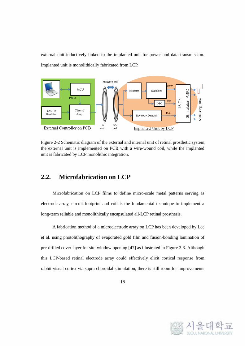
external unit inductively linked to the implanted unit for power and data transmission.
Implanted unit is monolithically fabricated from LCP.
Figure 2-2 Schematic diagram of the external and internal unit of retinal prosthetic system;
the external unit is implemented on PCB with a wire-wound coil, while the implanted
unit is fabricated by LCP monolithic integration.
2.2. Microfabrication on LCP
Microfabrication on LCP films to define micro-scale metal patterns serving as
electrode array, circuit footprint and coil is the fundamental technique to implement a
long-term reliable and monolithically encapsulated all-LCP retinal prosthesis.
A fabrication method of a microelectrode array on LCP has been developed by Lee
et al. using photolithography of evaporated gold film and fusion-bonding lamination of
pre-drilled cover layer for site-window opening [47] as illustrated in Figure 2-3. Although
this LCP-based retinal electrode array could effectively elicit cortical response from
rabbit visual cortex via supra-choroidal stimulation, there is still room for improvements
19
in its fabrication process for achieving higher mechanical robustness and long-term
reliability. The limitations of the previous LCP microfabrication are discussed and the
improved technologies are discussed in the following sections.
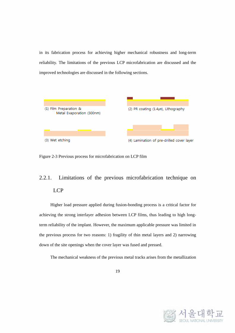
Figure 2-3 Previous process for microfabrication on LCP film
2.2.1. Limitations of the previous microfabrication technique on
LCP
Higher load pressure applied during fusion-bonding process is a critical factor for
achieving the strong interlayer adhesion between LCP films, thus leading to high long-
term reliability of the implant. However, the maximum applicable pressure was limited in
the previous process for two reasons: 1) fragility of thin metal layers and 2) narrowing
down of the site openings when the cover layer was fused and pressed.
The mechanical weakness of the previous metal tracks arises from the metallization

20
using evaporation with 100~200 nm-thickness. Such thin film metal layer is not robust
enough to withstand the mechanical stress of high load pressure (>150 kPa) during
thermal lamination, resulting in disconnection or crack. This issue could be resolved by
realizing thick (>1 μm) metal patterns through gold electroplating.
The narrowing of the originally designed site openings was inevitable in the
previous techniques where a pre-drilled low-temperature LCP film was thermally
laminated as a cover layer. The melted LCP cover layer film under pressure during
thermal lamination reflows and blocks the initial drill-holes in unpredictable manner
resulting in not only decreased but also non-uniform site opening sizes and site
impedances. This phenomenon becomes significant in case of the opening diameters in
the range of sub-millimeter making it almost impossible to implement a high-density
retinal electrodes array for higher resolution. The lamination pressure cannot be
compromised as it is a critical factor for strong interlayer adhesion and thus for long-term
reliability. Misalignment between underlying metal pads and the holes in the cover layer
is another problem as depicted in Figure 2-4. These limitations were overcome by
developing laser-ablation process for exposing the underlying metal at each site windows.

21
Figure 2-4 Problems associated with the previous method laminating a cover layer with
pre-drilled holes: misalignment and cover layer reflow.
Another drawback of previous process was the relatively high stiffness of electrode
which is an unfavorable property for being inserted into soft, delicate and curvilinear
retinal space. The LCP electrode thickness could not be less than 50 μm due to limited
options from the commercially available LCP film products (25 μm-thick film is the
thinnest among Vecstar series of Kuraray). Despite the similar Young’s modulus
(2~4GPa), LCP electrode had higher stiffness than polyimide- and parylene-based
electrodes of which thickness could be controlled in spin coating or vapor deposition
process. Dry etching can be used for thinning the LCP films, but it is a time-consuming
task due to low etch rate (~0.25 μm/min reported in [58]). In order to enhance the
flexibility of LCP electrode, a fast and simple laser-thinning process was developed to
thin LCP electrode array down to desired thickness by precisely controlling the laser
parameters.
The comparison of the previous and newly proposed microfabrication process on
LCP film is presented in

22
Table 2-I. In the following section, the improved fabrication techniques for a LCP
retinal electrode array including electroplating, laser-ablation and laser-thinning is
described in order to achieve higher mechanical robustness, long-term reliability and
flexibility.
Table 2-I Comparison of the previous methods and the proposed new methods for
microfabrication on LCP
Previous
Method New Method Improvements
1) Metal thickness 300 nm
(Evaporated)
5 μm
(Electroplated)
Mechanical robustness
Stronger adhesion**
2) Electrode array
Thickness 50 μm
Thinned to
25-30 μm Higher flexibility
3) Site
opening
Pre-drilled
cover layer Laser-ablation
Less misalign
No cover layer reflow
Stronger adhesion**
** by allowing higher-pressure lamination
2.2.2. Improved LCP-based microfabrication
The improved fabrication process for LCP-based retinal electrode array
incorporating the abovementioned features of electroplating up to 5 μm, laser-thinning for
higher flexibility and laser-ablation for site-window opening is schematically illustrated

23
in Figure 2-5.
Figure 2-5 Improved microfabrication process on LCP
2.2.2.1. Electroplated micro-patterning
First, seed layer of Ti/Au (50/100 nm) was evaporated onto 25 μm-thick LCP film
(Vecstar series, Kuraray) (Figure 2-5(1)) after solvent rinsing in acetone/methanol/IPA
and plasma activation using RIE etcher (Plasma lab, Oxford; O2, 100 sccm, 150 W, 3
min.). Not shown in the figure, the LCP film was attached on the 4-inch host silicon
wafer by using spin-coated silicone elastomer layer (MED-6233, Nusil) as a temporal
adhesive. A 10 μm-thick photoresist (AZ4620) was spun on the seed layer at 2,000
revolutions per minutes (rpm) for 40 seconds and baked at 30 seconds at a hotplate of

24
110. A FCG mask of negative image was used to define the photoresist mold using an
aligner (MA-6, KarlSuss; 70 sec, 20mW/cm2) and developer (3~4 min. in 300 MIF, no
dilution) as shown in Figure 2-5(2). The photolithographically structured photoresist
served as a mold during the gold electroplating up to 5 μm as in Figure 2-5(3). The thick
metal patterns for retinal electrodes array is completed after removing the PR mold in 700
MIF solution, followed by seed layer removal in aqua regia for Au and diluted HF (1%)
for Ti as in Figure 2-5(4). A LCP cover layer without site opening holes is laminated on
the metal patterns by thermal bonding process as shown in Figure 2-5(5).
To evaluate the photolithography and electroplating process, the cross-sectional
profiles of photoresist mold (Figure 2-5(2)) and electroplated metal tracks (Figure 2-5(4))
were observed by SEM (Scanning Electron Microscopy; FE-SEM S4800, Hitachi).
2.2.2.2. Laser-thinning for higher flexibility
In order to thin the LCP electrode array down to the thickness of 20~30 μm for
higher flexibility, grating patterns were engraved from the both faces of the electrode
using a 355 nm UV laser machine (Samurai system, DPSS, CA) as shown in Figure
2-5(6)). Laser parameters associated with the grating pitch (alternating vertical and
horizontal grating patterns of 25 μm period) were optimized for precise control over the
amount of etching.

25
The thickness of thinned electrode was measured through cross-sectional SEM
images and its improved of flexibility was quantitatively evaluated through force
measurement in bending test as illustrated in Figure 2-6 following the experimental
protocol presented in [43].
Figure 2-6 Bending force measurement for comparing the flexibility before and after the
laser-thinning process
2.2.2.3. Laser-ablation for site opening
Site windows for interfacing with neural tissues were defined through laser-
ablation process by exposing the metal site from the overlying LCP cover layer as in
Figure 2-5(7). The key factor for successful ablation is to completely remove the
overlying LCP layer but not to affect the surface morphology of underlying metal site.
For that, the LCP ablation process was tailored using the identical laser system to the
thinning step by varying the parameters of power, pulse rate, scan speed and pulse width.
After the optimal pulse rate had been established that selectively etch away the LCP cover
with minimized effect on metal surface, the amount of power (combination of power

26
(0~100%), scan speed, pulse width and repetition time) was determined for the complete
removal of LCP cover layer.
To ensure the complete ablation of overlying LCP and to observe any adverse
effect on the microscopic surface morphology of exposed gold site, the opened electrode
sites were assessed through scanning electron microscopy (SEM) and electrical
impedance spectroscopy (EIS) for comparison with an electroplated gold site without
laser treatment.
Finally, iridium oxide (IrOx) is deposited on the exposed gold sites for higher
charge storage and injection (Figure 2-5(8)). The electrodeposition of IrOx (EIROF)
using potentiostat will be published elsewhere. The electrochemical properties of the IrOx
and Au electrode are compared by EIS and cyclic voltammetry (CV).
The microfabrication process discussed in this chapter is utilized in the following
section of monolithic integration.
2.3. All-LCP Monolithic Fabrication
The retinal prosthetic device consists of mainly three functional blocks as shown
inFigure 2-7: 1) a coil for wireless reception of power and data, 2) circuit for generating
16 channel stimulation pulses and 3) a 16-channel retinal electrode array, all of which are
integrated into a homogeneous LCP substrate forming a monolithic system. This chapter
describes a novel monolithic fabrication steps to create an all-LCP retinal prosthesis

27
integrated by coil, circuit and electrode array, which is schematically shown in Figure 2-8.
Figure 2-7 The retinal prosthetic device consists of mainly three functional blocks: 1) a
coil for wireless reception of power and data, 2) circuit for generating 16-channel
stimulation pulses and 3) 16-channel retinal electrode array
Electrical components of electrode array, stimulator circuit and multilayered coil
are independently created in multiple LCP layers and integrated into a multilayered
substrate by fusion bonding (a). The system substrate is thermally deformed into an eye-
confirmable structure (b) which is followed by circuit assembly (c). After packaging (d),
the device is finalized by laser-machining steps (e). The completed device is surgically
implanted into eye (f).
Each step will be discussed in detail in the following sections from 2.3.1 to 2.3.5.

28
Figure 2-8 Monolithic fabrication process of LCP-based retinal prosthesis: (a)
independent film fabrication and thermal lamination to form a multilayered substrate, (b)
thermal deformation using a metal jig pair for eye-conformable curvature, (c) assembly of
stimulator ASIC and surrounding circuitries, (d) encapsulation of electronics by LCP
powder, (e) laser-machining and (f) surgical implantation into an eye.

29
2.3.1. Multilayered integration
2.3.1.1. Electrical components
The multilayered system substrate for the LCP retinal prosthesis integrated by
electrical components including planar coil, stimulating circuit and electrode array
consists of five metal layers in six LCP films as shown in Figure 2-9 with the CAD
designs for each layer shown in Figure 2-10.
The coil layer with through-hole vias interconnecting top and bottom sides was
fabricated from 100 μm-thick copper-clad LCP films of high melting temperature (HT-
LCP; 330, ULTRALAM 3850, Rogers Corporation, USA) through industrial flexible
PCB technology (Flexcom, Ansan, Korea). The multilayer coil was designed by
optimization of the geometric parameters using finite element methods (FEM) as
described in the previous publications [48, 68]; the top and bottom layers have 15 and 13
windings, respectively, both with 120 μm line width and 120 μm spacing. The wavy
structure at the octagonal corner is intended for providing stretchability to metal tracks for
the following deformation process of 2.3.2.
The circuit layer is carrying the footprints of the retinal stimulating circuit
constituted of rectifier, regulator, oscillator, envelope detector, integrated circuit for
stimulation (ASIC) and DC-blocking capacitors as shown by schematic diagram in Figure
2-7. The circuit layer was fabricated from a 50 μm-thick copper-clad HT-LCP films
(ULTRALAM 3850) through the same technology as the coil layer.
30
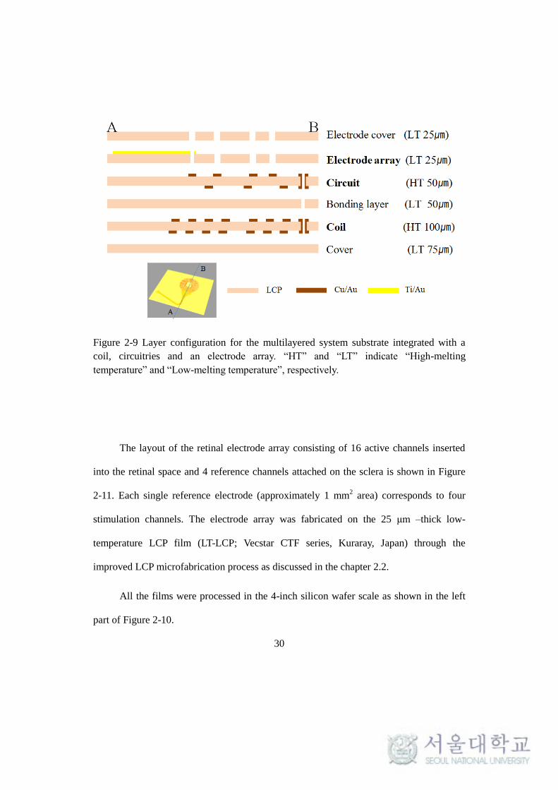
Figure 2-9 Layer configuration for the multilayered system substrate integrated with a
coil, circuitries and an electrode array. “HT” and “LT” indicate “High-melting
temperature” and “Low-melting temperature”, respectively.
The layout of the retinal electrode array consisting of 16 active channels inserted
into the retinal space and 4 reference channels attached on the sclera is shown in Figure
2-11. Each single reference electrode (approximately 1 mm2 area) corresponds to four
stimulation channels. The electrode array was fabricated on the 25 μm –thick low-
temperature LCP film (LT-LCP; Vecstar CTF series, Kuraray, Japan) through the
improved LCP microfabrication process as discussed in the chapter 2.2.
All the films were processed in the 4-inch silicon wafer scale as shown in the left
part of Figure 2-10.

31
Figure 2-10 CAD designs for multilayered system substrate; (a) coil bottom, (b) coil top,
(c) circuit bottom, (d) circuit top, (e) electrode array and (f) electrode cover layer. The left
two images show the whole layout on the 4-inch host wafer and one single unit.

32
Figure 2-11 the retinal electrode array layout: (a) 16 channel stimulation electrode array
and (b) 4 reference electrodes
2.3.1.2. Thermal lamination
Thermal lamination of multiple LCP films was well established in a previous work
[47]. In this study, much higher lamination pressure than the previous work could be
applied to achieve stronger interlayer adhesion and thus improve the long-term reliability,
thanks to the improved microfabrication with electroplating and laser-ablation as
discussed in 2.2. The enhanced long-term reliability as a result of the higher lamination
pressure will be quantitatively evaluated in the in vitro test section in 2.5.
After surface activation by oxygen plasma (100 sccm, 150 W, 3 minutes) of the
bonding surfaces, the LCP layers are fixed into align pins of metal jig pair as shown in
Figure 2-12. The LT-LCP films of various thicknesses (see Figure 2-9) are placed

33
between the functional layers serving as bonding and insulation. When the films were
heated up to the target temperature of 285 in the ramp rate of 420/hour, the pressure
of 400 Kgf/4”-wfaer was applied and maintained for 30 minutes using a heatig press
(model 4330, Carver, USA). Those films are formed into a single body of multilayered
LCP substrate by melting the LT bonding layers between them. The pressure was released
after the press is cooled down to room temperature. The laminating condition including
temperature and pressure versus time is illustrated in Figure 2-13.
After thermal lamination, the interlayer connections (electrode array to circuit, and
coil to circuit) were established by filling conductive silver epoxy (H20E, Epo-tek) in via
holes.
Figure 2-12 Thermal lamination of multiple LCP layers using heating press

34
Figure 2-13 A heating press (left) and the lamination recipe including temperature and
pressure versus time
2.3.1.3. Layer configuration
The layer configuration of the multilayered structure is shown in Figure 2-9. The
overall thickness of 350 μm and the composition of each film layers are the result of a
compromise between long-term reliability and yield. Higher pressure during the thermal
bonding of the LCP layers can strengthen the interlayer adhesion leading to higher long-
term reliability in aqueous conditions. Although thicker layers can allow a higher
lamination pressure with less probability of undesired contact between the metal patterns
in the adjacent layers, a thick substrate is difficult to deform because the
tensile/compressive stress increases with the film thickness as shown in Figure 2-17. The
overall thickness and the composition of the films in Figure 2-9 is therefore the result of
optimization so that it can be successfully deformed as well as endure the lamination and

35
packaging process at 285 with 4 Kgf/cm2 for 30 minutes, which is the condition found
through preliminary experiments that provides sufficient LCP-LCP adhesion.
2.3.2. Thermal deformation
The second step is thermal deformation of the multilayered substrate to create an
eye-conformable structure. Deformation method is described, followed by evaluation of
mechanical and electrical effects.
2.3.2.1. Deformation process
The thermoplastic property of LCP can be utilized to deform the film into a non-
planar structure by applying heat and pressure as illustrate in Figure 2-14. The
multilayered LCP substrate integrated by coil, circuit and electrode array is placed
between a metal jig pair having concave and convex profiles of targeting shape. After
heated up to 230 in a heating press, which is higher than the glass transition
temperature but lower than the melting temperature, the assembled jig is pressed by 1~2
tons/4”-wafer load. The metal jig pair for LCP deformation is specially designed to have
bump-like structures at the edge such that the gap between the top and the bottom jig is
maintained constant regardless of the strength of the load pressure as marked by red circle
in Figure 2-14. Maintaining a constant gap between the jig pair during thermal pressing is
essential for achieving uniform thickness throughout the deformed LCP film and thus
preserving the multilayered structure.
36
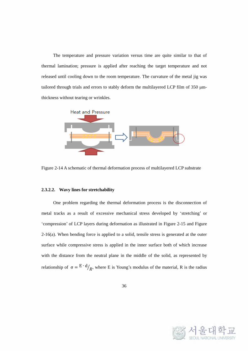
The temperature and pressure variation versus time are quite similar to that of
thermal lamination; pressure is applied after reaching the target temperature and not
released until cooling down to the room temperature. The curvature of the metal jig was
tailored through trials and errors to stably deform the multilayered LCP film of 350 μm-
thickness without tearing or wrinkles.
Figure 2-14 A schematic of thermal deformation process of multilayered LCP substrate
2.3.2.2. Wavy lines for stretchability
One problem regarding the thermal deformation process is the disconnection of
metal tracks as a result of excessive mechanical stress developed by ‘stretching’ or
‘compression’ of LCP layers during deformation as illustrated in Figure 2-15 and Figure
2-16(a). When bending force is applied to a solid, tensile stress is generated at the outer
surface while compressive stress is applied in the inner surface both of which increase
with the distance from the neutral plane in the middle of the solid, as represented by
relationship of σ = E ∙ d𝑅⁄ , where E is Young’s modulus of the material, R is the radius
37
of the curvature, d is the distance from the neutral plane.
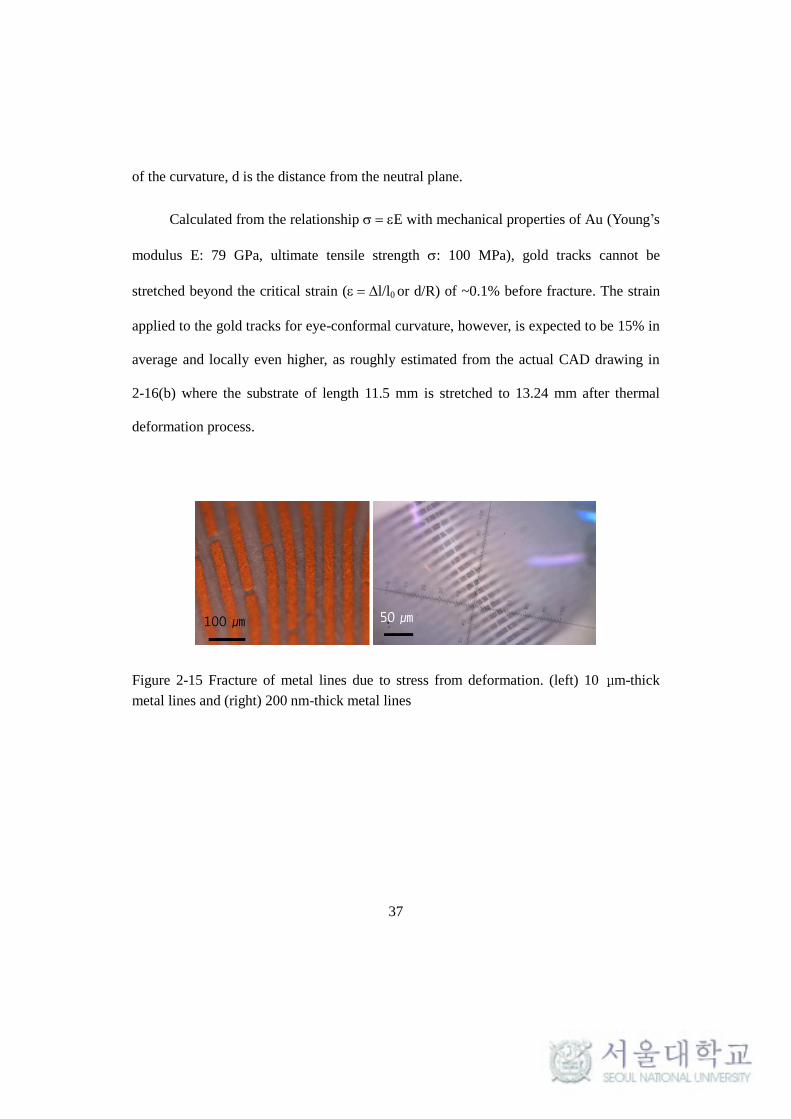
Calculated from the relationship E with mechanical properties of Au (Young’s
modulus E: 79 GPa, ultimate tensile strength : 100 MPa), gold tracks cannot be
stretched beyond the critical strain (l/l0 or d/R) of ~0.1% before fracture. The strain
applied to the gold tracks for eye-conformal curvature, however, is expected to be 15% in
average and locally even higher, as roughly estimated from the actual CAD drawing in
2-16(b) where the substrate of length 11.5 mm is stretched to 13.24 mm after thermal
deformation process.
Figure 2-15 Fracture of metal lines due to stress from deformation. (left) 10 μm-thick
metal lines and (right) 200 nm-thick metal lines

38
Figure 2-16 (a) Generation of compressive and tensile stress during deformation of the
multilayered substrate; (b) cross-sectional CAD drawing to show the actual profile of the
curvature required for eye-conformable device.
To prevent metal line fractures during deformation, metal tracks were designed to
have wavy (or ‘serpentine’) shapes that can provide stretchability upon tension or
compression, which have been successfully utilized in the field of stretchable electronics
[69-72]. The geometric characteristics defining the serpentine shape, including the width

39
of the tracks w, minimum line distance d, tracks pitch p, opening angle θ and radius r
were varied according the degree of deformation for five different regions (I-V) around
the electrode lead and coil as shown in Figure 2-17. The optimized values for the five
locations that could survive the stress from the deformation with a minimum line pitch
are summarized in Table 2-II.
Figure 2-17 Geometrical parameters defining the wavy metal tracks for providing
stretchability (a), five locations of different wavy shapes according to the degree of
deformation (b).
Table 2-II CHARACTERISTICS OF THE WAVY LINES
Electrode Coil
I II III IV V
w 30 30 25 130 130
d 37 30 25 85 85
r 40 30 40 300 620
θ 240 180 90 120 130
P 150 100 65 230 240
* unit in
40
2.3.2.3. Electrical properties of the deformed coil
In addition, the electrical properties of the spherically deformed coil were
estimated to verify any adverse effects from deformation process on the wireless link
performance. Three-dimensional finite elements models (FEM) were built using
FastHenry solver [73] to compare the inductance, resistance and quality factor of the
deformed coil with those of the planar coil.
2.3.3. Circuit Assembly
A stimulator ASIC and discrete components are assembled on the curved surface
after deformation to constitute a retinal stimulating pulse generator.
2.3.3.1. Stimulation ASIC
A 16 channel stimulator ASIC previously published in [44] was wire-bonded on the
deformed substrate. Central area of 5 mm-diameter was maintained flat during the
deformation for stable bonding of the ASIC (3.3 mm ⅹ 3.3 mm). The stimulator ASIC
used for this sytem is shown in Figure 2-18 along with its specifications.
The 16-channel stimulation circuit consists of four current drivers each of which is
responsible for 4 active channels and 1 reference channel. Among the 4 channels of each
current driver, any combination of two active channels can be selected for bipolar
stimulation, or the reference channel can be paired to one to four active channels for
monopolar stimulation. The pulse rate and pulse duration ranges can be adjusted by

41
varying an off-chip oscillator output, which is set to 10 kHz in this study for retinal
stimulation providing the pulse rate of 2 to 30 Hz and the pulse duration of 0 to 6 ms.
Figure 2-18 stimulation ASIC used in the retinal stimulation system; die photo on the left
and the detailed specifications on the right [44]
2.3.3.2. Surrounding circuitries
The surrounding circuitries for power and data recovery from the induced signal at
the receiver coil illustrated in Figure 2-7 are implemented by commercially available
discrete components as shown in the schematic of Figure 2-19. The devices used for each
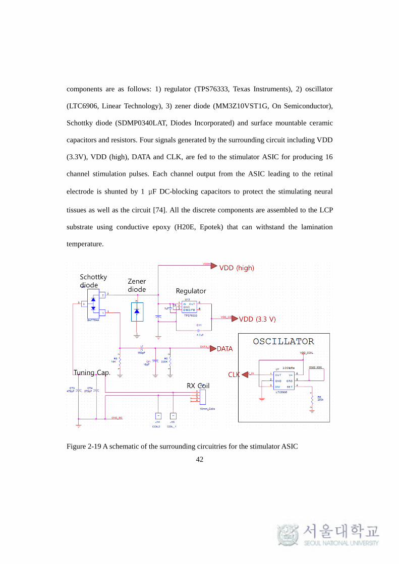
42
components are as follows: 1) regulator (TPS76333, Texas Instruments), 2) oscillator
(LTC6906, Linear Technology), 3) zener diode (MM3Z10VST1G, On Semiconductor),
Schottky diode (SDMP0340LAT, Diodes Incorporated) and surface mountable ceramic
capacitors and resistors. Four signals generated by the surrounding circuit including VDD
(3.3V), VDD (high), DATA and CLK, are fed to the stimulator ASIC for producing 16
channel stimulation pulses. Each channel output from the ASIC leading to the retinal
electrode is shunted by 1 μF DC-blocking capacitors to protect the stimulating neural
tissues as well as the circuit [74]. All the discrete components are assembled to the LCP
substrate using conductive epoxy (H20E, Epotek) that can withstand the lamination
temperature.
Figure 2-19 A schematic of the surrounding circuitries for the stimulator ASIC

43
2.3.4. Packaging
After assembly of the circuit, packaging process is followed to encapsulate the
electronics against body fluids. Packaging of electronics on a curved substrate poses
several challenges in applying uniform pressure throughout the bonding surface. In
addition, if an air-cavity is left inside, expansion and contraction of the air inside the
package during thermal cycle up to 285 can lead to undesired deformation of the
package. To address these issues, a LCP powder-filling packaging technique was
developed: the concave volume accommodating the electronic components was filled
with house-milled LT-LCP powder and covered by a 25 μm-thick pre-curved lid of LT-
LCP. They were thermally pressed under the same condition as the lamination using a
pair of metal jigs leaving a void inside when combined as shown in Figure 2-20. The
melted LCP powder can fill the internal space to achieve a thin, eye-conformable, and
monolithic system package. This filling-and-melting method offers the additional benefits
of being mechanically robust and moisture condensing inside the package is less likely
than a package with an air-cavity.
Figure 2-20 Schematic illustration of the LCP-packaging process filling and melting LCP

44
powder in the curved volume
2.3.5. Laser Machining
The final step is the series of laser-machining. The laser process discussed in
chapter 2.2.2 as well as [46] was identically applied for this steps including thinning of
the retinal electrode part for higher flexibility by applying grating laser patterns,
electrodes site opening by laser-ablation, and final outlining described in detail. The
device is completed after plasma cleaning to remove laser burr.
2.4. Device characterization
The functionality and reliability of the fabricated device were tested in bench. The
wireless operation was verified by delivering power and data from an inductively linked
primary coil into the device soaked in PBS solution. The primary coil was driven by a
custom-built external unit on a printed circuit board (PCB) that consisted of a
microcontroller to generate PWM data to control the stimulation parameters of ASIC and
a class-E amplifier for 2.54 MHz modulation.

45
2.4.1. Transmitter Circuit and Wireless Operation
2.4.1.1. Transmitter circuit
A transmitter circuit with a transmitter coil was developed for wireless power and
data delivery into the implanted unit. This external unit controlled by a cable-connected
PC interface is not capable of generating real-time retinal stimulating patterns
corresponding to the external scenery, but can produce instructions for static pattern
stimulation with varying parameters of amplitude, pulse width and pulse rate. This
capability is considered to be sufficient for verifying the functionality of the new LCP
retinal implant in animal model and acute clinical trials, but further development of real-
time stimulation with external camera is required for practical applications to chronic
tests with blind patients.
The transmitter circuit implemented on a printed circuit board (PCB) consists of a
microcontroller unit (MCU), class-E amplifier and an oscillator as in Figure 2-21(a). The
MCU (ATmega 16, Atmel) programmed by AVR software via wire-connected PC
generates pulse-width-modulated (PWM) binary data stream carrying stimulation
command for the implanted stimulator circuit. The class-E amplifier acts as a high-
efficient amplifier as well as a data modulator for simultaneous wireless transmission of
power and data: the PWM binary data is fed to the drain of the class-E amplifier to
alternatively turn on and off the transistor while being modulated by 2.54 MHz oscillator.
The output of the amplifier drives a transmitting coil tuned to oscillate at 2.54 MHz.

46
The actual schematic of these circuitries is shown in Figure 2-21(b) which was
implemented on PCB with commercial off-the-shelf components. Note that a few
subsidiary logics such as switches, power supplying circuit, connectors are omitted in the
schematic. The period of single PWM data is 8 μs with duty cycle of 75% for binary ‘1,’
25% for binary ‘0’ and 50% for ‘end of frame.’
2.4.1.2. Transmitter coil
A transmitting coil was created by winding litz-wire (6 strands of 50 μm diameter)
and molding it by silicon elastomer (Med-6233, Nusil) as less geometric restriction is
imposed on the external coil compared to the implanted coil. The outer and inner
diameter of the spiral transmitter coil is 30 mm and 10 mm, respectively, within a
thickness less than 200 μm. The transmitter coil was tuned to oscillate at 2.54 MHz using
tuning capacitors as shown in Figure 2-21.
2.4.1.3. Wireless operation test
In order to verify the functionality of the developed device in aqueous condition,
the wireless operation of the completed device was tested in PBS solution. The developed
LCP retinal implant was soaked in the bath filled with PBS solution and the transmitter
coil was approached to the bath for wireless transfer of power and data as shown in
Figure 2-22. The output current pulse was monitored by oscilloscope from the connector

47
module hard-wired to the electrode sites.
Figure 2-21 schematics of the transmitter circuit: (a) simplified diagram chart showing
the components and (b) actual implemented circuit for MCU, class-E amplifier and
oscillator

48
Figure 2-22 Test setup for wireless operation of the completed device in aqueous
condition
2.4.2. Electrochemical measurements
Electrochemical impedance spectroscopy (EIS) and cyclic voltammetry (CV) of
the fabricated retinal electrode array coated by IrOx were measured with the Solatron
1260 and 1287 system (Solatron, UK). A three-electrode cell was configured for the
measurements using an Ag/AgCl reference electrode and a mesh-type Pt counter
electrode in PBS solution (1X, Gibco). The EIS was measured for frequencies from 10
Hz to 10 kHz by applying a sinusoidal of 10 mV amplitude without an offset. The CV
curve was recorded in the -0.8 to 0.6 V range at a scan rate of 50 mV/s for which the
cathodic area was integrated to calculate the charge storage capacity (CSC) using the
CorrView software.

49
2.5. Long-term reliability tests in vitro
As discussed earlier in chapter 1.6, although polymer-based biomedical implant
can offer important advantages over conventional metallic packages including flexibility,
lightness, miniaturization, and compatibility with a low cost batch-process, the
quantification its long-term reliability has not been well established. In this chapter,
therefore, a series of testing methods for all-polymer devices are proposed and applied to
the newly developed LCP-based retinal implant for evaluating its long-term reliability in
vitro. First the leakage pathways of polymer-based device in aqueous environment are
defined and then those failure mechanisms are quantitatively addressed by in vitro
experiments in accelerated condition as well as by analytic calculation
2.5.1. Failure mechanisms of an all-LCP device
The pathways for moisture penetration in the LCP-based retinal implant (also in
generic polymer-based implants) can be categorized into three interfaces: I) through the
bulk material, II) through the polymer-polymer adhesion and III) through the polymer-
metal adhesion shown in Figure 2-23. A series of studies were designed and carried out to
address those leak pathways assessing the long-term reliability of the LCP-based implant
as follows. First, water diffusion through bulk material was analytically calculated with
Fick's laws to estimate the barrier property of LCP against moisture. Second, in vitro tests
were conducted in accelerated conditions to investigate water ingress through the

50
adhesive interfaces of the LCP-LCP and the LCP-metal from three aspects: 1) reliability
of the electrode part in terms of encapsulation and electrochemical stability, 2) reliability
of the package by measuring the leakage current inside the enclosure, and 3) long-term
functionality of the complete device.
Figure 2-23 (a) Moisture penetrating pathways divided into I) LCP surface, II) LCP-LCP
adhesion and LCP-metal adhesion in LCP-based retinal implant, (b) detailed schematic of
the electrode part including type I, II, III leakages and (c) a package part having I and II
interfaces (d).

51
Table 2-III Leakage pathways and corresponding testing methods
Leak Interface Description Evaluation method I. LCP surface I-(1) electrode surface
I-(2) package outer cover (see 2.5.2) Calculation
I-(3) package lid into cavity
II. LCP-LCP adhesion II-(1) package seal
(see 2.5.3.3) Accelerated soak
test of package parts
II-(2) electrode sidewall (see 2.5.3.1) Accelerated soak
test of electrode parts III. LCP-metal adhesion III-(1) electrode site opening
The specifically categorized pathways of moisture ingression are shown in Figure
2-23(b) for the electrode part, and in Figure 2-23(c) for the package part, all of which are
summarized in Table 2-III along with the corresponding testing methods to address those
leakage mechanisms. Moisture permeation through I) the LCP surface was analytically
calculated based on diffusion theory, while water ingress through II) the LCP-LCP and III)
the LCP-metal interface was investigated experimentally in vitro with the separated
electrode parts and package parts.
2.5.2. Analytic calculation
Unlike metallic packages, a polymer wall has intrinsic gas permeation through the
surface by diffusion even in the absence of leak channels. Fick’s diffusion laws can be
used to analyze the moisture diffusion within a polymer barrier as well as to predict the
relative humidity inside a polymer enclosure [75-77]. Permeant molecules are adsorbed
and dissolved in the surface of polymer matrix based on Henry’s law with solubility S,

52
which can be calculated as [63]:
𝑆 =(𝜌𝑝𝑜𝑙𝑦𝑚𝑒𝑟)×(
𝑓𝑟𝑎𝑐𝑡𝑖𝑜𝑛𝑎𝑙
𝑚𝑎𝑠𝑠 𝑔𝑎𝑖𝑛)×(
𝑚𝑜𝑙𝑒𝑐𝑢𝑙𝑎𝑟
𝑣𝑜𝑙𝑢𝑚𝑒 𝑎𝑡 𝑇)
(𝑚𝑜𝑙𝑒𝑐𝑢𝑙𝑎𝑟 𝑤𝑒𝑖𝑔ℎ𝑡). (1)
The sorption is subsequently followed by diffusion of permeant through the
polymer towards lower concentration represented by diffusion coefficient, D. The
permeability coefficient P of a molecule in a polymer is the product of the solubility and
the diffusion coefficient, P = DS.
Figure 2-24 1-D problems with boundary and initial conditions to solve Fick’s law for
analyzing water diffusion into LCP surface in three cases: (a) I-(1): an electrode, (b) I-(2):
outer cover into the coil, (c) I-(3) package lid into an air cavity.
Table 2-IV Parameters of LCP barrier and package

53
Parameter Value Unit Description
d 25~75 m Barrier thickness
A 3.50 cm2
Surface area
V 0.2 cm3
Cavity volume
Sa
0.79 cm3
/cm3
Solubility
Db
3.79 x 10⁻¹³
cm2
/s Diffusion coefficient
Pc
2.99 x 10⁻¹³
cm2
/s Moisture permeability
a S was calculated from (1) using water absorption rate of LCP provided by Kuraray Vecstar datasheet.
b D was calculated from the relationship P=DS
c P value was also from datasheet and converted to cm2/s
Three pathways of moisture permeation through bulk material, I-(1), I-(2) and I-(3)
of Figure 2-23, are represented in Figure 2-24(a), (b) and (c), respectively, with
corresponding boundary and initial conditions. In the first case I-(1) illustrated in Figure
2-24(a) (redrawn from the box marked by ** in Figure 2-23(b)), both sides of
LCP/metal/LCP electrode of 50 m-thickness are exposed to moisture with the same
vapor pressure pa (at 37°C, 100% RH). In the second case I-(2) of Figure 2-24(b)
(redrawn from the box marked by *** in Figure 2-23(c)), moisture diffuses from a 75
m-thick outer cover into the coil windings while the other side is impervious to water.
Because the first case is equivalent to the second case with a thickness of d1/2 due to its
symmetry, we used an analytic solution of Fick’s second law for an 1-D problem in figure
2(b) with d = 25 m for C1(x,t) and 75m for C2(x,t) to calculate the transient moisture
transmission within the LCP barrier given by (2) [78, 79]:

54
𝐶(𝑥, 𝑡) = 𝐶𝑎′ − ∑4(𝐶𝑖−𝐶𝑎′)
(2𝑛−1)𝜋(−1)𝑛 cos
(2𝑛−1)𝜋𝑥
2𝑑exp − [
(2𝑛−1)𝜋
2𝑑]
2𝐷𝑡
∞
𝑛=1
(2)
, where d is the film thickness, Ca’ is the concentration at the polymer surface, Ca is the
ambient moisture concentration. The third case I-(3) in Figure 2-24(c) for estimation of
the relative humidity (RH) inside the air cavity with the volume V and the surface area A
can be calculated using Tencer’s simplified quasi-steady state (QSS) model shown in (3)
[76, 80]
𝑹𝑯𝒕 = 𝑅𝐻𝑎 [1 − 𝑒−𝑡
𝜏 ], (𝑅𝐻𝑡 = 0 𝑎𝑡 𝑡 = 0) (3)
, where the time constant is defined as
𝜏 = 𝑉𝑑
𝑃𝐴+
𝑑2
2𝐷. (4)
This simplified QSS model has been shown to provide a good approximation of the
full transient model except at the very beginning of the time course [76, 80]. The
humidity inside the LCP package was estimated using the parameters summarized in
Table 2-IV. The curved surfaces in the cross-section of the eye-conformable package and
array were simplified to flat models in Cartesian coordinate in Figure 2-24 considering
that the radius of the curvature (5~10 mm) is far greater than the thickness of the curved
surface.
The second case, I-(2), corresponds to the limiting factor for a power-filled LCP
package because permeation from the other side of the package has a far longer diffusion
55
length to reach metal tracks or active components. The model in I-(3) represents a LCP
package with an air cavity inside. The electrode part, I-(1), is common for the both cases.
2.5.3. Long-term reliability tests in accelerated environment
The LCP-based retinal implant consists of mainly two parts: a retinal electrode
array and a circular package. The reliability was assessed for each part as well as using
the complete device; an evaluation by components can provide a more quantitative
understanding of the degradation process from a wide range of observables, while the
information available from the complete device is limited to, in our case without back-
telemetry, the binary pass/fail functionality check.
2.5.3.1.
2.5.3.2. Long-term reliability of electrode array
The reliability of LCP-LCP adhesion has been previously investigated by Lee et al.
where the LCP-LCP encapsulation without a site opening prevented water ingression for
more than a year in an accelerated condition of 75°C saline measured by the leakage
current between the interdigitated electrodes (IDEs) [49]. Moisture penetration through
LCP-metal adhesion around site openings, however, has not been investigated yet. In this
study, the 16-channel retinal electrode array part was examined under an accelerated
environment to assess the long-term reliability of both the LCP-LCP and the LCP-metal
interface shown in Figure 2-25(a). The test samples for the electrode part were fabricated

56
by i) micro-patterning, ii) electroplating, iii) seed layer removal, iv) cover layer
lamination, and v) site opening and outlining shown in in Figure 2-25(b) [48], with the
same design and process used by the electrode array in the complete system except that
iridium oxide (IrOx) was not deposited on the electroplated gold and that electrode was
terminated by connector pads.
The electrode samples were soaked in a bath filled with PBS maintained at 87°C on
a hotplate as shown in in Figure 2-25(a). The adjacent two channels (marked in red in the
figure) were continuously pulsed in a bipolar manner (biphasic pulse with 50 A intensity,
500 s pulse width, and 20 Hz repetition). The exposed area of the electrode sites was
half the size of the underlying meal pads such that the penetration of conductive saline
solution leads to an expansion of the metal-electrolyte interface area and thus a drastic
decrease in the voltage amplitude (see Figure 2-23(b)). The voltage transient between two
bipolar channels was frequently monitored by an oscilloscope (DPO 4034, Tektronix) to
detect water ingress through the LCP-LCP or LCP-Au interface. The failure criterion was
set to a voltage amplitude drop below half of the initial values. The experiments were
performed with two sets of electrodes, one fabricated with high lamination pressure (400
kgf/4"-wafer =500 kPa) using the standard recipe in our technology [81], and the other
with low-pressure (60 kgf/4''-wafer =75 kPa) to assess the effect of the lamination
pressure upon the adhesion strength between the LCP and LCP, as well as the LCP and
metal. For each pressure, the mean time to failure (MTTF) from three samples was
averaged.
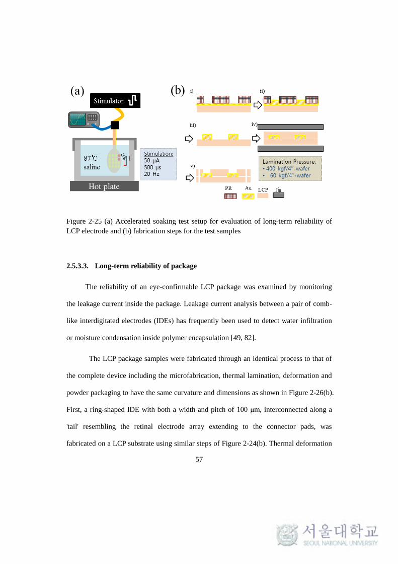
57
Figure 2-25 (a) Accelerated soaking test setup for evaluation of long-term reliability of
LCP electrode and (b) fabrication steps for the test samples
2.5.3.3. Long-term reliability of package
The reliability of an eye-confirmable LCP package was examined by monitoring
the leakage current inside the package. Leakage current analysis between a pair of comb-
like interdigitated electrodes (IDEs) has frequently been used to detect water infiltration
or moisture condensation inside polymer encapsulation [49, 82].
The LCP package samples were fabricated through an identical process to that of
the complete device including the microfabrication, thermal lamination, deformation and
powder packaging to have the same curvature and dimensions as shown in Figure 2-26(b).
First, a ring-shaped IDE with both a width and pitch of 100 μm, interconnected along a
'tail' resembling the retinal electrode array extending to the connector pads, was
fabricated on a LCP substrate using similar steps of Figure 2-24(b). Thermal deformation

58
followed to achieve an eye-confirmable structure, in which the metal tracks could survive
due to their stretchability provided by the wavy shapes to withstand the
tensile/compressive stress caused by deformation. The sample was soaked in 87°C PBS
after encapsulation by melting and filling the LCP powder inside the curved cavity as
described earlier in 2.3.4. The leakage current between the IDE under 5V DC bias was
measured with a pico-ammeter (model 6485, Keithley) as shown in Figure 2-26(a). The
failure criteria were set to a leakage current higher than 1 A following previous studies
[49]. Data from three samples were averaged to calculate the MTTF.
Figure 2-26 Accelerated soaking test setup for long-term reliability test of LCP package
and (b) fabrication steps of the test samples
2.5.3.4. Long-term reliability of complete device
Despite the limited information obtained from the test using a finalized device, the

59
importance of its long-term assessment should not be overlooked. The complete system is
soaked in PBS at an elevated temperature of 67°C. The functionality of the system was
frequently inspected by confirming the generation of output current pulses with the
intended parameters. The measurements were conducted in dry conditions by directly
contacting the electrode sites using oscilloscope probes.
2.5.4. Long-term electrochemical stability
The long-term electrochemical stability of the LCP-based electrode array coated by
electrodeposited IrOx (EIROF) was also investigated. The preparation of the samples was
identical to the above experiment except that the IrOx was deposited on the Au and
accelerated not by temperature but by pulse rate. The electrode samples soaked in 37°C
PBS were continuously pulsed by current amplitudes ranging from 80 A to 640 A with
a repetition rate of 200 Hz, which is approximately x6.7 acceleration considering that
pulse rates less than 30 Hz have generally been used in clinical studies for retinal
stimulation [12, 16]. The voltage transient, impedance spectrum (EIS), and cyclic
voltammetry (CV) as well as scanning electron microscope (SEM) images were
compared before and after stimulation for 30 days (~5x10⁸ pulses). The EIS and CV were
measured with the Solatron 1260 and 1287 system in a three-electrode cell using an
Ag/AgCl reference electrode and a Pt mesh counter electrode in PBS. The EIS was
measured for 10 Hz to 10 kHz with a sinusoidal of 10 mV amplitude, and the CV curve
was recorded in the -0.8~0.6 V range at a 50 mV/s scan rate for which the cathodic area

60
was integrated to compute the charge storage capacity (CSCc).
2.6. Acute and Chronic Evaluation in vivo
To demonstrate the functionality and implantation stability of the LCP-based
retinal prosthesis, in vivo animal experiments were performed with New Zealand white
rabbits. The in vivo tests were conducted in two aspects: (1) verification of wireless
operation and stimulation efficacy using a fully functional device by recording cortical
response in response to retinal stimulation and (2) long-term implantation stability of the
device using LCP dummy devices by observing any adverse symptoms around the device
for more than a year.
2.6.1. Surgical implantation
A new surgical technique was developed by our ophthalmologic partner to implant
the LCP-based retinal prosthesis into rabbit eye by inserting the retinal electrode into
suprachoroidal space and fixing the circular package on the sclera. All procedures
conformed to the ARVO Statement for the Use of Animals in Ophthalmic and Vision
Research.
General anesthesia was induced by intramuscular injection of tiletamine/zolazepam
(Zoletil; Carros, France) and xylazine (Rompun; Bayer AG, Germany) in a 1:1 mixture at
a dose of 0.6 mL/kg. After a superior conjunctival incision along the limbus, a

61
subconjunctival pocket was made for inserting the circular system package into the
superior-temporal quadrant. The electrode array was then inserted into the suprachoroidal
space under funduscopic examination through a 3-mm superior-nasal scleral incision
made parallel to the limbus. After positioning inside the subconjunctival pocket, the
circular package was fixed on the sclera by two suturing holes as illustrated in Figure
2-27. The final step is to suturing the conjunctiva along the limbus leaving the implant
within the space between sclera and conjunctiva.
Figure 2-27 Description of the surgical implantation and fixation of the LCP-baser retinal
implant in a rabbit model

62
2.6.2. Acute functionality test
The functionality of the device was verified by recording electrically evoked
cortical potentials (EECPs) in response to the stimulation of the rabbit retina by biphasic
current pulses generated from the implanted device (cathodic-first, amplitude 200 μA,
pulse duration 500 μs, pulse rate 2 Hz).
Following the surgical implantation of a LCP retinal prosthesis as in 2.6.1, two fine
holes was drilled in the skull to insert a needle-type recording electrode and a reference
electrode as shown in Figure 2-28. A recording electrode was placed in the visual cortex,
6 mm anterior and 4 mm contra-lateral to the lambda, while the reference electrode was
inserted in 20 mm anterior to the lambda. The counter electrode was inserted subdermally
in the ipsilateral ear.
To begin the electrical stimulation, the primary coil for power and data transfer was
approached and attached on the skin around eyelid as shown in Figure 2-27. Before
electrical stimulation, visually evoked potential (VEP) was measured as a control under
the full-field light stimulation (EW-202/LS-C, Mayo Corporation).
The evoked potential in response to retinal stimulation was recorded by a ML-132
bio-amplifier (AD Instruments) and a Powerlabs 4/20 system (AD Instruments, USA).
The bio-amplifier was set to filter the raw signal within the band pass range of 2 Hz to
200 Hz to observe local field potential. Filtered signal was post-processed by MATLAB
to average 100 to 200 repetitions for higher signal to noise ratio.

63
Figure 2-28 EECP measurement setup with needle-type electrodes and a bio-amplifier
2.6.3. Long-term implantation stability
To evaluate the long-term implantation stability and biocompatibility, dummy
devices that were physically identical to the actual device but not functionally were
implanted in two New Zealand white rabbits using the same surgical procedure as above.
The devices have been implanted for more than a year to observe any adverse events such
as protrusion of the device, inflammatory changes, electrode migration and retinal
damage through fundus examination and optical coherence tomography (OCT) imaging.

64
3. Chapter 3: Results
3.1. Microfabrication on LCP
The results of the new microfabrication process on LCP using electroplating, laser-
ablation and laser-thinning are presented. The electroplated patterning process is applied
in the fabrication of retinal electrode layer in 3.2.1, while the two techniques using laser
are utilized in the final step of the LCP monolithic integration for the LCP retinal implant
in 3.2.5.
3.1.1. Electroplated micro-patterning
The microfabrication steps on LCP film using electroplating of gold up to 5 μm are
shown in Figure 3-1. The LCP film attached on 4-inch host wafer in Figure 3-1(a) shows
photolithographically patterned PR mold of 10 μm thickness. Its cross-sectional view
from SEM images in Figure 3-1(c) confirms the thickness of PR with 10 μm and well-
defined PR structures for the minimum line width of 10 μm having a slope of 83°. The
ring pattern around the edge is opened for electrical contact for electroplating.
65
The same LCP film after electroplating, PR removal and seed layer removal is
shown in Figure 3-1(b) leaving only thickened metal tracks on LCP. The cross-sectional
SEM image of the electroplated metal lines up to 5 μm are presented in Figure 3-1(d),
where the line width and spacing are 25 μm and 10 μm, respectively. The resolution bar
in Figure 3-1(f) shows the minimum line width and spacing for this process is
approximately 10 μm. The fabricated LCP-based retinal electrode which will be used in
the following step of the multilayered integration for monolithic all-LCP retinal implant is
shown in Figure 3-1(e).
Thick metal tracks realized by this electroplating process could endure the higher
lamination pressure for stronger interlayer adhesion compared to previous technology
with 100~200 nm-thick metal layers. The improved long-term reliability as a result of
stronger interlayer adhesion is quantitatively examined through in vitro accelerated soak
test as discussed in 3.4.2.

66
Figure 3-1 Microfabrication using gold electroplating on LCP: (a) negatively patterned
PR mold by photolithography and (c) its cross-section SEM image; (b) completed micro
patterning on LCP after electroplating and seed layer removal and (d) its cross sectional
SEM image, (e) fabricated retinal electrode layer and (f) the magnified view of metal
tracks and pads for resolution test

67
3.1.2. Laser-ablation for site opening
Laser parameters for opening the site windows by ablation of overlying LCP layer
as well as for laser-thinning process were tabulated in Table 3-I. It has been found that the
gold pad was barely affected by laser beam with higher pulse rate than 65 KHz by which
could effectively ablate the LCP cover layer. The SEM image of ablated site opening of
200 μm diameter is shown in Figure 3-2(a). The slope of laser-ablated sidewall is
approximately 68˚. In the test sample, the cover layer was intentionally weakly laminated
and peeled off after site opening so that the surface of the laser-opened gold pad can be
compared with the original surface. As can be seen from the SEM image in Figure 3-2(b),
the laser-ablation process did not induce significant change in the surface morphology of
electroplated gold site but minor residues which could be readily removed by oxygen
plasma. The preservation of gold surface could be also confirmed through the comparison
of impedance spectrum of laser-opened electrode with non-treated electroplated gold pad
as shown in Figure 3-3. The magnitude of impedance at 1 KHz increased from 7.6KΩ of
electroplated site as it is to 9.8KΩ of laser-opened site. The increased impedance is
mainly attributed to the slight decreased roughness of gold site after laser treatment.

68
Table 3-I Laser parameters for laser-ablation and laser-thinning
Ablation Thinning
Power (%) 0.1 80
Scan speed (um/s) 1000 100
Pulse rate (KHz) 65 20
Pulse width (us) 10 20
Repetition 5 1
Figure 3-2 SEM image of a site opened by laser-ablation (a) 200um-diameter electrode
opening, (b) comparison between surface morphology of a gold pad non treated by laser
[A] and laser-ablated pads [B]

69
Figure 3-3 Comparison of impedance spectrum between laser-opened gold electrode and
non-treated electrode: magnitude (top) and phase (bottom).
3.1.3. Laser-thinning for higher flexibility
By engraving horizontal and vertical 25 μm-pitch grating alternatively with laser
parameters of Table 3-I, a 50 μm-thick LCP electrode could be evenly thinned down to
approximately 30 μm thickness as shown in Figure 3-4. The enhancement of flexibility
was quantitatively measured through a bending test and its result is plotted in Figure 3-4

70
which represents the measured force required to bend the electrode with one end clamped.
The acquired data was fitted with polynomial of degree 1 using Matlab software. By
comparing the slopes of fitted lines, which reduced from 1.3 mN/mm (original) to 0.67
mN/mm (laser-thinned), it could be confirmed that bending force decreased by about half
using laser-thinning process which suggests improved flexibility of LCP electrode.
Figure 3-4 Laser-thinning of LCP electrode for higher flexibility: (a) a cross-sectional
SEM image of thinned electrode down to ~25 μm thickness; (b) comparison of bending
force measurement between original 50 um-thick electrode and 30 um-thick thinned
electrode.

71
3.2. All-LCP Monolithic fabrication
3.2.1. Multilayered integration
The layer stacking steps for the multilayered integration is shown in Figure 3-5 in
the scale of a 4-inches host wafer in (a) and a magnified view for a single unit in (b). The
independently fabricated coil layer, circuit footprints layer, and electrode layers are
sequentially stacked with bonding layers between them as shown in the film
configuration of Figure 2-9. These film stacks were thermally laminated together to form
a 350 μm-thick multilayered system substrate. The electroplated metal tracks could allow
thermal pressure of 400 kgf/4”-wafer (~500 kPa) in 285 without any disconnection or
mechanical damage of metal lines.

72
Figure 3-5 Multilayer lamination steps in the scale of a 4-inches host wafer in (a) and a
magnified view for a single unit in (b), both showing the stacking of functional and
bonding layers including 1) outermost coil cover, 2) double-sided coil layer, 3) bonding
layer, 4) double-sided circuit layer, 5) retinal electrode layer, 6) electrode cover layer and
6) the thermally laminated substrate

73
3.2.2. Thermal deformation
3.2.2.1. Deformation results
The multilayered substrate after thermal deformation for eye-confirmable structure
is shown in Figure 3-6. The top surfaces of an individual piece cut from its 4-inch host
fixed in a metallic jig before and after deformation are shown Figure 3-6(a-b) while the
bottom faces showing the deformed coil are shown in (c-e). The coil cover layer was
removed here to demonstrate the deformed coil patterns. The mechanical and electrical
properties of the deformed system substrate are discussed in the following sections.
Figure 3-6 (a-b) The top face fixed in deformation jig before and after deformation and
(c) to (e) bottom face showing the deformed coil. The cover layer was removed for
demonstration.

74
3.2.2.2. Wavy lines for stretchability
The fabricated wavy metal tracks used to survive the mechanical stress from the
deformation are shown in Figure 3-7 at three different locations (I-III). The wavy tracks
of the coil (IV, V) are shown in Figure 3-6(c). The serpentine metal tracks at different
locations are fabricated to have the geometric parameters summarized in Table 2-II. All
the wavy metal tracks remained intact after the deformation to the curvature desired for
this eye-conformable device as verified by the resistance measurements.
Figure 3-7 Fabricated wavy metal tracks in three different locations for providing
stretchability to survive mechanical stress during the deformation process.
3.2.2.3. Effect on the electrical properties
FEM models of planar and spherical coil in FastHenr to estimate the changes in
electrical properties as a result of spherical deformation of planar coil are shown in the
Figure 3-8 (a) and (c) along with the fabricated LCP coil before and after deformation in
(b) and (d). The simulated and measured electrical properties of the deformed coil are
compared with the planar coil in Table 3-II. Despite the slight difference between the
simulated and measured data, likely due to the imperfection in modeling the deformed
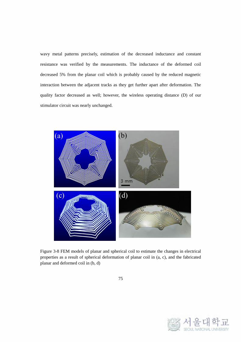
75
wavy metal patterns precisely, estimation of the decreased inductance and constant
resistance was verified by the measurements. The inductance of the deformed coil
decreased 5% from the planar coil which is probably caused by the reduced magnetic
interaction between the adjacent tracks as they get further apart after deformation. The
quality factor decreased as well; however, the wireless operating distance (D) of our
stimulator circuit was nearly unchanged.
Figure 3-8 FEM models of planar and spherical coil to estimate the changes in electrical
properties as a result of spherical deformation of planar coil in (a, c), and the fabricated
planar and deformed coil in (b, d)

76
Table 3-II ELECTRICAL PROPERTIES OF THE DEFORMED COIL
Simulated
Measured
R
(Ω)
L
(μH) Q*
R
(Ω)
L
(μH) Q*
D
(mm)
Planar
Coil 6.02 7.45 19.4
6.33 7.7 19.1 16
Deformed
Coil 6.03 6.69 17.4
6.35 7.3 18.1 16
* quality factor at 2.54 MHz, **D: wireless operation distance
These mechanical and electrical properties of the deformed substrate presented in
this chapter confirm that the spherical formation did not adversely affect the performance
of the electronics integrated in the curved LCP substrate.
3.2.3. Circuit assembly
The stimulating circuit assembled on the deformed substrate and its typical signals
from the wireless operation are shown in Figure 3-9. The circuit footprints on the
deformed substrate in figure (A) are assembled using an 16-channels stimulator ASIC and
discrete components constituting peripheral circuitries such as a rectifier, a regulator, a
oscillator and an envelope detector as shown in figure (B).
The waveforms from representative nodes in the stimulating circuit are: (a) PWM
signal modulated by a 2.54 MHz carrier induced at the receiver coil, (b) after rectification,
(c) decoded PWM data stream, (d) regulated power of 3.3 VDC and (e) the output

77
biphasic current pulse across a 1 kΩ load.
Figure 3-9 Circuit assembly on the curved substrate (A to B); typical waveform from
wireless operation: PWM signal modulated by a 2.54 MHz carrier induced at the receiver
coil (a) after rectification (b), decoded PWM data stream (c), regulated power (d), and the
output biphasic current pulse across a 1 kΩ load (e).
3.2.4. Packaging
The results from the packaging step to encapsulate the electronics by LCP powder-
filling technique is shown in Figure 3-10. Assembled electronics on the curved substrate
is filled by LCP powder as in Figure 3-10(a), and then thermally pressed to melt and fill
the LCP powder within the curved volume without defect. The cross-section of the
encapsulated electronics package is shown in Figure 3-10(b). The melted powder filled

78
the inner volume evenly without any observation of voids or defects. The multilayered
substrate could endure the packaging temperature and pressure preserving its laminar
structure without collapsing or an interlayer short circuit.
Compared to the LCP package leaving an air cavity inside, the powder-filling
package can offer advantages in that the moisture condensation inside a package is less
likely and the package itself is mechanically stronger, despite the disadvantages of higher
thermal conduction from electronics to tissue and slight heavier weight as summarized in
Table 3-III.
Figure 3-10 Results of LCP packaging: (a) powder-filling package for encapsulation of
the electronics and (b) its cross-sectional view showing the void-free filling with well-
preserved multilayered structure after packaging process

79
Table 3-III Comparison of LCP packages with an air cavity and a power- filled package
Air Cavity Filled
Mechanical Strength Weak Good
Heat transfer to eye
(Thermal conductivity W/(m∙)) 0.025 0.084
Weight 0.25g 0.40g
Water condensing Possible Unlikely
3.2.5. Laser machining
The device is finalized through a series of laser-machining including 1) laser-
thinning, 2) laser-ablation for site opening and 3) outlining, using the optimized laser
parameters discussed previously in the section 3.1.2 and 3.1.3. The electrode part thinned
by engraving grating pattern by laser is shown in Figure 3-11(a) and site-opening for 16-
channels windows for the retinal electrode is shown in Figure 3-11(b). The final outlining
process using laser is presented in Figure 3-11(c) for electrode part and (d) for package
part, completing the LCP-based retinal prosthesis cut from the host substrate as shown in
Figure 3-11(e).

80
Figure 3-11 Laser-machining process for (a) laser-thinning and (b) site-opening by laser-
ablation and outlining of (c) electrode (d) package and (e) overall view
3.3. Device Characterization
The completed LCP-based retinal prosthesis fabricated by monolithic integration
and deformation is shown in Figure 3-12. This device is characterized in the following
sections.

81
3.3.1. General specifications
The completed LCP-based retinal prosthetic device is shown in Figure 3-12, and its
characteristics are summarized in Table 3-IV. The device has a circular package
accommodating the electronics with a 14 mm diameter and 1.3 mm maximum thickness
for its crescent-shaped cross-section that can be conformally attached on the eyeball as
shown in Figure 3-12(a) and (b).
The electrode part to be inserted into the retina has a thickness of 25 μm after the
laser-thinning process, which etched away the LCP starting from a 350 μm thickness, and
is pre-curved to fit the eye-curvature shown in Figure 3-12(c). This device is
geometrically comparable to the Ahmed glaucoma valve (16 mm x 10 mm x 1mm, 0.3 g;
Model FP7, New World Medical, Inc.) which has been clinically proven to be stably
attached on the eye-surface for more than a decade shown in Figure 3-12(d). Because the
surgical procedure attaching the device in the conjunctival pocket with episcleral suturing
is also similar, our device is expected to be stably attached on the temporal side of the
eyeball over an extended period of time.
This LCP-based retinal prosthesis weighs only 0.38 g, which is less than a tenth of
conventional implantable devices with a metal package. Considering that the weight of an
eyeball is about 5 g, this weight reduction is a significant improvement in patients’
discomfort as well as implantation stability

82
Figure 3-12 Fabricated LCP-based retinal prosthesis: (a) comparison with a dime, (a) the
device on a model eye showing conformal attachment, (c) electrode part pre-curved to fit
the eye-curvature, (d) comparison with a Ahmed glaucoma valve, (e) inner surface of the
device and (f) magnification of the retinal electrode array coated by iridium oxide.
Table 3-IV Specifications of the LCP-based retinal prosthesis
Parameter Value
Parameter Value
Package Size 14 mm Wireless Operating Distance 16 mm
Max. thickness 1.3 mm
Number of Electrodes 16
Weight 0.38 g Current Amplitude 10 μA~10 mA
Volume 0.22 cc Pulse Duration* 0~6 ms
Pulse Rate* 2~30 Hz

83
3.3.2. Transmitter circuit and coil
A transmitter circuit consisting of a MCU for generating PWM data frame and a
class-E amplifier for driving the primary coil is shown in Figure 3-13(a). The circuit is
implemented on a PCB of 10 mm-width by 6 mm-height by soldering discrete
components including MCU (ATmega16), L, R, C, regulators, an oscillator, LED diodes,
power MOSFETs, connectors and switches. The stimulation parameters can be conrolled
via a PC interface. The transmitter coil wound by litz-wire and molded in a silicone
rubber is shown in Figure 3-13(b).
Figure 3-13 Transmitter circuit for generating and amplifying PWM data to control the
stimulating parameters in (a) and transmitter coil in (b)
3.3.3. Wireless operation
The functionality of the completed device was tested through wireless operation by
confirming the generation of biphasic pulses having the stimulation parameters as
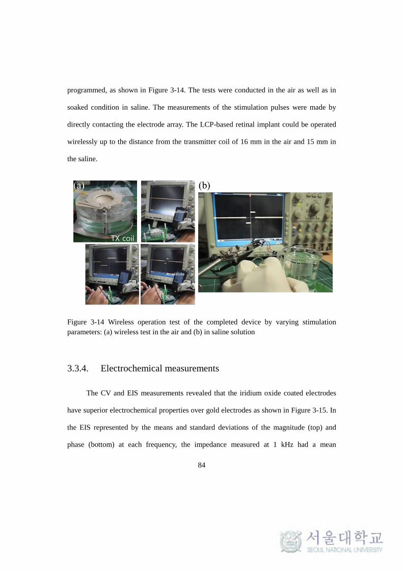
84
programmed, as shown in Figure 3-14. The tests were conducted in the air as well as in
soaked condition in saline. The measurements of the stimulation pulses were made by
directly contacting the electrode array. The LCP-based retinal implant could be operated
wirelessly up to the distance from the transmitter coil of 16 mm in the air and 15 mm in
the saline.
Figure 3-14 Wireless operation test of the completed device by varying stimulation
parameters: (a) wireless test in the air and (b) in saline solution
3.3.4. Electrochemical measurements
The CV and EIS measurements revealed that the iridium oxide coated electrodes
have superior electrochemical properties over gold electrodes as shown in Figure 3-15. In
the EIS represented by the means and standard deviations of the magnitude (top) and
phase (bottom) at each frequency, the impedance measured at 1 kHz had a mean

85
magnitude of 1.2 ± 0.06 kΩ which is about a 27-fold decrease for Au. The more resistive
phase of IrOx-coated electrode than Au electrode over the entire frequency range can be
explained by the different charge transfer natures of IrOx and gold, reversible faradaic
process and capacitive charge transfer, respectively [83, 84]. Integration of the cathodic
area from the cyclic voltammetry in Figure 3-16 suggests that the charge storage capacity
(CSC) of the IrOx electrodes is 27.8 ± 0.84 mC/cm2, which is a 70-fold increase from Au.
The averaged impedance and CSC values are summarized in Table 3-V.
Figure 3-15 Electrochemical characterizations of the retinal electrodes array coated with
iridium oxide: EIS as represented by the means and standard deviations of the magnitude

86
(top) and phase (bottom) at each frequency
Figure 3-16 Cyclic voltammetry (CV) of the retinal electrode array with IrOx (left) and
Au (right)
Table 3-V Averaged electrochemical properties of the IrOx-coated retinal electrode array
parameter value
@ 1
kH
z |Z| (Ω) 1.20
Phase (°) -4.6
CSC (mC/cm2)
27.8
3.4. Long-term reliability tests in vitro
Result from the analytic calculation is presented, followed by in vitro and in vivo
tests. While the accelerated aging test using electrode samples are finished, tests with the
package parts and the complete device are still ongoing without failure at the time of this
writing.

87
3.4.1. Analytic calculation
The analytically calculated moisture diffusion through LCP barrier is shown in
Figure 3-17. Transient moisture distribution inside a LCP electrode in I-(1), represented
by moisture concentration within the film normalized to ambient moisture concentration
at 20 linearly spaced time steps for 3 years is plotted in Figure 3-17(a). It shows the
moisture diffusion from both surfaces exposed to water into the LCP film, finally
saturating the whole region with Ca’. The increase of moisture concentration according to
time at the position of metal tracks, x=0 for both I-(1) and I-(2), is shown in Figure
3-17(b). Although concentration inside the LCP film (C1(0,t), C2(0,t)) reached 63% of
ambient moisture concentration (Ca) at t=0.3 and 3.5 years for I-(1) with d1=25 m and I-
(2) d2=75 m, respectively, in both cases the moisture concentration did not exceed the
saturated value of Ca’= Spa which is lower than Ca due to the solubility(S) of water to
LCP less than 1. The excellent barrier property of LCP due to very low S was discussed in
terms of molecular structure in [85]. It seems also consistent with our previous study
where a leakage current inside a 25 μm-thick LCP encapsulation slowly increased likely
due to moisture diffusion, but well maintained below a few nano-amperes for more than a
year in 75°C PBS. The leakage current abruptly increased above mili-amperes as a result
of moisture infiltration through LCP-LCP adhesion. The calculation here also suggests
that the leakage current between metal tracks beyond LCP barrier could be maintained
sufficiently low for extended period of time even after C1,2(0,t) is saturated.
Growth of relative humidity inside the cavity of a LCP package calculated using

88
Tencer’s model is plotted in Figure 3-17(c) for three lid thicknesses. Time constants at
which the RH(t) reaches 63% are 15.3 years for d3=25 m, 31.2 years for d3=50 m and
64.3 years for d3=100 m. Unlike d1 and d2 which cannot be increased due to stiffness
concern and difficulty in deformation process, respectively, less constraints are imposed
on the thickness of d3 implying opportunities to further improve the reliability of a LCP
package with air cavity. Considering that formation of 4-8 monolayers of liquid water
occurs around 70-90% of RH on hydrophilic surface and even higher for hydrophobic
surface [76] the analytic calculations proposed here are also suggesting a good barrier
property of LCP against moisture permeation.

89
Figure 3-17 Analytically calculated moisture diffusion through LCP barrier: (a) transient
moisture concentration distribution inside a LCP electrode, I-(1), normalized to ambient
moisture concentration at 20 time steps in 3 years, (b) Moisture concentration within LCP
barrier at the position of metal layer (x=0) versus time for I-(1) and I-(2), (c) RH inside a
LCP cavity versus time for three lid thicknesses with their time constants.
90
3.4.2. Long-term reliability tests in accelerated condition
3.4.2.1. Long-term reliability of electrode arrays
A fabricated LCP electrode array for an accelerated aging test is shown in Figure
3-18(a) along with the typical voltage waveforms measured from intact and leaked
electrodes in Figure 3-18(b). The average mean time to failure (MTTF) of the LCP-based
electrode arrays laminated with a pressure of 400 kgf/4"-wafer was 114 days in 87°C PBS
shown in Figure 3-18(c). Variation in the cathodic peak voltage (Vpeak) according to the
soaking time plotted in Figure 3-18(d) showed that water ingression occurred in three
phases. The first phase represents an intact electrode characterized by negligible deviation
in the Vpeak values from the initial amplitudes. Water penetration through the LCP-metal
adhesion allowed the electrolyte to access the underlying metal pads seen in the second
phase at which the Vpeak suddenly drops to approximately half of the initial values
(marked by circle). It is estimated that water ingress in this stage was limited within the
metal pads which are twice as large as the opened area. After 2~ 7 days in the second
phase, the third phase immediately followed to expose a further area along the
interconnecting lines finally leading to almost the disappearance of the Vpeak. This three-
phase degradation process is supposed to be an evidence of water infiltration through the
LCP-metal interface rather than the LCP-LCP interface; otherwise, the leakage would
have occurred abruptly without an intermediate second phase related to the ratio of the
exposed/underlying metal area. As seen in Figure 3-18 (c), the pressure applied during the
thermal lamination of multiple LCP films significantly influenced the long-term reliability.

91
A higher lamination pressure could extend the MTTF from 21 to 114 days by
achieving stronger interlayer adhesion in the LCP-LCP interface as well as the LCP-metal
interface. In the low-pressure samples, phase II and phase III could not be distinguished.
It is also noteworthy that the pulsed channels failed earlier than the non-pulsed channels
suggesting that electrochemical stress caused by the current pulsing adversely affected the
Figure 3-18 Electrode parts tested under an accelerated condition: (a) fabricated 16-ch
electrode test samples, (b) typical waveform from intact and leaked channels, (c)
comparison of the averaged mean time to failure (MTTF) of samples laminated with high
pressure (stimulated/not-stimulated) and low pressure. (d) Variation in the Vpeak from
each test samples with high pressure (HP) and low pressure (LP) according to time
showing three phases of degradation process.

92
LCP-metal adhesion promoting water ingression through it. The difference between the
mean values was statistically insignificant, but for each test sample, the unstimulated
channel always failed later than the stimulated channels.
3.4.2.2. Long-term reliability of package
Eye-confirmable LCP packages for the accelerated soak test were fabricated as
shown in Figure 3-19. A spherically deformed LCP substrate with a ring-shaped IDE and
a dummy chip is shown in Figure 3-19(a). The completed package is shown in Figure
3-19(b) with a FPC connector, after encapsulated by the LCP powder-filling method. The
Figure 3-19 Package test samples for accelerated aging tests: (a) deformed LCP substrate
before encapsulation showing a ring-shaped interdigitated electrode (IDE) and a dummy
chip, (b) completed package samples after encapsulation and outlining, (c) leakage
current measured between IDE inside the package under 5V DC bias.

93
leakage currents measured from each package samples soaked in 87°C saline solution are
plotted in Figure 3-19(c) along with the their means and standard deviations. The leakage
current is slowly increasing but well maintained below 2 nA for 35 day which is a similar
trend to the previous study using LCP encapsulation in 75°C saline [49].
3.4.2.3. Long-term reliability of complete device
The complete device has maintained its functionality for more than 35 days in an
accelerated aging test in 67°C saline solution confirmed by directly contacting the
electrode channels to monitor the biphasic pulse with an oscilloscope. The aging tests
using a complete device and package parts are ongoing at the time of this writing.
3.4.3. Long-term Electrochemical stability
The results of the long-term electrochemical stability test with the IrOx coating are
shown in Figure 3-20. The cathodic peak voltage values did not experience great changes
throughout the test period showing the largest increase of 17% as plotted in Figure 3-20
(a). This trend was consistent with the EIS measurements in Figure 3-20(b) in which the
averaged impedance magnitude |Z| at 1 kHz increased 21% from 2.1 k before
stimulation to 2.52 k after stimulation. The magnitude increment was greater in
frequencies lower than 1 kHz, while the phase decreased (more capacitive) over the
whole frequency range. The typical CV curve after continuous stimulation had a similar
shape and area compared to that of before pulsing as plotted in Figure 3-20(c). The CSCc

94
values calculated by integrating the cathodic area of the CV curves for each stimulation
strength confirmed that the decrease in CSCc values after stimulation was less than 18 %
as shown in Figure 3-20(d). The IrOx site subjected to pulsing with higher current
amplitude resulted in a greater decrease rate for CSCc. The SEM images comparing the
surface morphology of IrOx before and after pulsing with 640 mA in Figure 3-20(e)
revealed that a highly porous microscopic structure was well preserved.
Figure 3-20 Electrochemical stability of IrOx coating: (a) changes in peak voltages for the
four stimulation strengths, (b) comparison of impedance spectrum before and after
stimulation period (c) comparison of CV curve before and after stimulation, (d)
comparison CSC before and after stimulation for different stimulation amplitudes, (e)

95
SEM image of surface morphology before (e-1) and after stimulation(e-2).
3.5. Acute and chronic evaluation in vivo
3.5.1. Surgical implantation
The implantation of LCP-based retinal prosthesis in the rabbit eye through the
surgical procedure discussed in 2.6.1 is sequentially presented in Figure 3-21. After
subconjunctival pocket is opened for placing the package by conjunctival incision along
the limbus (a), a 3 mm scleral incision is made for electrode insertion (b). The electrode
part inserted into the suprachoroidal space via the scleral incision is positioned under
funduscopic observation (c), followed by a package placement within the subconjunctival
pocket (d). The circular package is fixed on the sclera by suturing two holes (e-f) and the
conjunctiva is pulled to cover the entire package (g). The surgery is completed by
suturing the conjunctiva around its initial incision around limbus (h-i).

96
Figure 3-21 Surgical procedure for suprachoroidal implantation of the LCP-based retinal
implant: (a) subconjunctival pocket, (b) scleral incision, (c) electrode insertion, (d)
package insertion, (e) 1st suturing hole, (f) 2
nd suturing hole, (g) conjunctival re-cover, (h)
suturing of re-covered conjunctiva and (i) finished (captured from video)
3.5.2. Acute functionality test
Following surgical implantation of the LCP retinal implant into the rabbit eye, the
EECP was recorded from the visual cortex as shown in Figure 3-22(a), where a
transmitter coil is approached over the eyelid to operate the implanted device and a

97
recording electrode inserted into visual cortex is interconnected by cables shielded by
aluminum foil. The averaged local filed potential evoked by electrical retinal stimulation
from the implanted device is presented in Figure 3-22(c) along with the potential evoked
by light stimulation as a control in Figure 3-22(b). Wireless operation of the implant by
an external coil could elicit robust cortical response represented by a positive peak (P1)
with a shorter latency than visually evoked potential [86, 87]. These results confirmed the
functional efficacy of the device.
Figure 3-22 In vivo evaluation of the LCP-based retinal prosthesis in a rabbit: (a)
schematic description of the surgical implantation of the device, (b) electrically evoked
and (c) visually evoked cortical potential confirming the functionality of the device,
3.5.3. Long-term implantation stability
In the in vivo stability test using dummy devices, fundus and ocular observation as
well as OCT imaging were performed after one year after the implantation. The
microscopic image in Figure 3-23(a) shows the device during the surgery after the

98
attachment of the device using two episcleral sutures before re-covering the conjunctiva,
whereas Figure 3-23(b) shows the same device after a year of implantation. The
recovered conjunctiva was well preserved without observation of any adverse effects such
as inflammation and protrusion of the device. A fundus image of Figure 3-23(c) shows
that the implanted array had not migrated or induced vitreous inflammation. A
representative OCT image in Figure 3-23(d) shows that the retinal structure containing
the LCP-based electrode array was well preserved for the postoperative 1-year period
without any choroidal retinal inflammation or structural deformations. Scleral or
conjunctival inflammations and complications were not observed around the implanted
package either. Further examinations on the retinal tissue such as histological analysis are
expected to help understand the structural effect of the LCP implant on the retinal
architecture.

99
Figure 3-23 (a) Circular package attached on the sclera using two sutures before re-
covering the conjunctiva, (b) the same device as in (a) after 1 year of implantation
showing well recovered ocular tissues, (c) a fundus and (d) OCT image (along the dashed
line in (c)) after 1 year of implantation showing no adverse effect such as retinal
inflammation

100
4. Chapter 4: Discussion
4.1. Comparison with conventional devices
The developed LCP-based retinal implant can be compared with conventional
retinal prosthetic devices with similar structure as summarized in Table 4-I. The most
outstanding feature is the device size. Despite of a little bigger diameter of the package
itself, the LCP retinal implant has about a half the thickness of other two devices with an
eye-conformable shape. Additionally the LCP device consists of a single part of package
and electrode array, unlikely the two parts configuration of previous devices that need an
additional coil part. The LCP-based device has another important advantage that the
homogeneous all-LCP body fabricated from monolithic integration removed the need for
feed-through technology which has been the most prominent cause of the device failure
as well as requires labor-intensive manual work for assembly.

101
Table 4-I Comparison of the developed LCP-based retinal implant with conventional
retinal prosthetic devices
USC-Secondsight [13] Boston group [40] This study
Device
Approach Epi-retinal Sub-retinal Suprachoroidal
Package material
Ti Ti LCP
Electrode Substrate Parylene-C Polyimide LCP
Feedthrough Yes Yes No
Number of Electrode
60 15 16
Device Size
Package (11mm x
11mm x 3.2 mm) +
additional coil part
Package (11mm x
11mmx 3 mm) +
additional coil part
One part (14 mm x
14mm x 1.3 mm)
Weight >5g
(estimation)
>5g
(estimation) 0.4 g

102
4.2. Potential applications
In this study, a novel LCP-based retinal prosthetic device that is thin, light and eye-
conformable was fabricated, and its functionality was verified in vitro and in vivo. Our
LCP monolithic fabrication process negates the need for expensive and labor-intensive
feed-through technology enabling a low-cost, batch manufacturing process. Although the
device reported here is designed as a retinal prosthesis, the concept and the fabrication
methodology are not limited to retinal applications. The advantages of this all-LCP retinal
prosthesis achieved by multilayered integration for miniaturization and manufacturability
are numerous. The thermal deformation process for conformal structure to the target
tissue/organ and the long-term reliability attained from the low moisture absorbing nature
of LCP are generally highly desired characteristics for any type of implantable biomedical
devices. The design and fabrication technologies established in this study, therefore,
could be used for other neural prosthetic applications as well, for example cochlear
implants, deep brain stimulation, bioreactors, and various central and peripheral nerve
stimulators
4.3. Opportunities for further improvements
The new retinal implant demonstrated in this study consisted of a circular package
that was 14 mm in diameter and 1.3 mm thick and a retinal electrode array with 16
channels. The bottleneck towards further miniaturization and higher numbers of channels
is in the stimulating electronics not in the LCP fabrication process. If the oscillator and

103
voltage regulator that are currently built using discrete components are integrated into the
ASIC design, the system package could be minimized to less than 10 mm in diameter and
0.5 mm thick. Because the need for a complicated feed-through process that limits the
high count lead to channels was removed by monolithic fabrication, our technology is
easily scalable to a higher number of electrodes. For instance, current LCP
microfabrication of a feature size less than 10 μm combined with multilayered routing
can produce a retinal electrode with more than 300 channels.
Additionally, further study is being conducted to further improve the long-term
reliability of the LCP-based package and electrode array, for example, by constructing a
special microstructure in the interface of the adhesion, and sophisticating the lamination
and packaging process to allow higher pressure during thermal bonding.
Another issue worth consideration is the effect of misalignment between the
transmitter coil attached on the glasses arm and the retinal implant fixed on the temporal
side of an eye-ball. Although the wireless performance discussed in this study was
measured from exactly aligned coil pair, movement of eyeball in clinical application can
result in lateral and angular misalignment leading to degraded wireless operation. One
simple method that can prevent malfunctions due to misalignment during clinical
application is to use a larger transmitter coil: higher input power is needed, but the
wireless link can be less sensitive to the coil position. If the diameter of the primary coil
is increased from 25 mm to 50 mm, as in the Argus II system, the developed device is
expected to be reliably operated in clinical trials. This is, however, not the fundamental

104
solution of the issue, so further studies are required for desensitization of the coil pair to
misalignment.
4.4. Long-term reliability
The long-term reliability of a LCP-based retinal prosthesis was evaluated by using
a series of tests specifically devised for all-polymer implants for which the hermeticity is
difficult to quantify with traditional methods for metallic packages. Although the recently
proposed LCP-based retinal prosthesis offers attractive properties such as a thin, light,
eye-confirmable package and compatibility with low-cost batch manufacturing, its
durability in an implanted environment is the top prerequisite for neural prosthetic
devices without which any other advantages cannot be exploited. Despite the high
potential of LCP as a biomaterial for chronic implantable devices due to its low water
absorption rate and gas permeability, no study yet has been done to quantitatively assess
the long-term reliability of an all-LCP neural prosthetic device.
Focusing on moisture ingress as the primary concern rather than helium leakage,
we examined the reliability of a LCP-based system through soaking tests in PBS at an
elevated temperature to accelerate aging. An accelerating temperature of 87°C for the
components testing (electrode and package) and 67°C for the complete system were
determined following the case of the Argus II retinal implant (Secondsight, CA) [44]. The
'10 degree rule' is commonly used to extrapolate the equivalent lifetime at 37°C from

105
MTTFs at accelerated temperatures stating that the rate of chemical reaction will be
doubled for every 10°C increase in temperature [88]. Because this rule is derived from
the Arrhenius equation using fairly gross approximations for which the accuracy declines
with the greater deviation from ambient temperature, it has been recommended that the
accelerating temperature should be kept below 60°C or 70°C [88, 89]. However, other
studies have suggested that the '10 degree rule' gives a conservative prediction on lifetime
in a wide range of accelerating temperatures for most polymers provided that any adverse
physical or chemical processes are not initiated that could not occur in normal operating
conditions [88, 90]. If this rule is applied to our results, the estimated MTTF at 37°C
would be roughly 10 years for the electrode array. Nevertheless, this prediction should be
used as a guide only without knowing the exact activation energy which can be acquired
from MTTFs at two different temperatures. Aging test at different temperature is
currently being conducted to calculate an accurate accelerating factor.
It was confirmed that higher lamination pressure significantly improved the
reliability of the LCP-LCP and LCP-metal interface by achieving stronger interlayer
adhesion. This observation is consistent with the diffusion theory stating that higher
pressure applied during thermoplastic polymeric bonding results in stronger adhesion by
means of promoting the inter-diffusion of polymer chains across the interface [91, 92]. A
weak lamination pressure (60 kg/4'-wafer) used to be applied for LCP films carrying
metal patterns of 100 to 200 nm-thicknesses that are mechanically too weak to endure
strong thermal pressing. A recent LCP fabrication process using electroplating up to a 5

106
m-thickness enabled high-pressure lamination (400 kg/4''-wafer). Because this
lamination pressure is neither an optimized condition nor the critical pressure above
which the metal tracks are damaged, there seems to be room for further enhancement of
the LCP-LCP and LCP-metal bonding by applying far stronger pressure. Stretchable
metal tracks enabled by a serpentine structure will help withstand the mechanical stress
during higher-pressure lamination.
The same rationale could be applied to improve the durability of a LCP package as
well. The reliability of the LCP package depends on the integrity of the LCP-LCP seal
created between the curved substrate and the curved lid film. One difficulty in achieving
strong adhesion at this sealing is the application of a uniform pressure throughout a
curved bonding area (marked by an asterisk in figure 1(d)). The powder-filling technique
could alleviate this problem somehow, yet still leaves other opportunities for
improvement through, for example, a more sophisticated jig design based on mechanical
simulation to analyze the load distribution at the bonding surface.
The other issue worth consideration about the LCP package is utilization of the
cavity inside the eye-confirmable enclosure. A LCP package with an air cavity inside can
be an alternative to current power-filling approach since it was analytically estimated to
provide good reliability with time constants ranging from 15 to 64 years. Another option
would be a use of desiccants such as silica gel and molecular sieves that can absorb
infiltrating moisture, which have been successfully applied to prolong the lifetime of
implantable devices [93-95]. The combination of desiccants, air volume and LCP powder

107
for filling the LCP package need to be optimized for maximum lifetime through
calculation as well as experiments.
An analytic calculation was based on the of Fick's diffusion law to estimate water
diffusion inside LCP barrier. Because Fick’ law generally describes the diffusion through
the amorphous polymer matrix, LCP which has highly crystalline structure may not be
fully analyzed using our simple model. More complex diffusion model is needed to more
accurately analyze the permeation through LCP wall characterized by unique molecular
packing arrangements that preclude dissolution and diffusion of even small molecules [75,
85, 96, 97].
In addition, this analytic model considers water permeation only through the LCP
surface, but it could be further improved by including other adhesively sealed leakage
paths in the calculation as proposed in [80]. In this literature, Tencer's model was adapted
to establish an electric analogy consisting of resistive and capacitive components that
represent the permeating behavior of various leakage pathways as well as the effect of a
desiccant, thus allowing a simple calculation of the time constant comprised of
contributions from different leakage paths. In order to build such a model for an LCP-
based implant, each component with its various interfaces including the LCP-LCP seals
and LCP-metal adhesion has to be experimentally determined.

108
5. Chapter 5: Conclusion
A novel retinal prosthetic device which is small, thin, light-weight and eye-
conformable was developed using monolithic fabrication and conformal deformation of
LCP. New microfabrication techniques on LCP film were developed adopting gold
electroplating, laser-thinning and laser-ablation. Electroplated thick metal tracks (5 μm)
and site opening by laser-ablation could allow thermal lamination with higher pressure
thus contributing to achieve stronger interlayer adhesion for higher long-term reliability.
A monolithic fabrication process using LCP as a substrate and packaging material was
established including multilayered integration, thermal deformation, LCP-power
packaging and laser-machining. Independently fabricated LCP films of coil, circuit and
electrode array were thermally laminated to form a single body of a multilayered system
substrate. The substrate was thermally deformed into an eye-confirmable curvature
without adversely affecting the electrical properties. The device was packaged by LCP
power-filling method after assembling circuit components on the curved substrate. The
device was completed after laser-machining steps of laser-thinning, laser-ablation and
outlining. The developed device with 16 channels has a circular package 14 mm in
diameter with a maximum thickness of 1.3 mm and a weight of 0.38 g, and was
wirelessly operated up to 16 mm in the air.

109
The long-term reliability of this LCP-based retinal prosthesis was evaluated in vitro
and in vivo with testing methods designed for all-polymer devices. Moisture leakage
pathways were divided into the LCP surface, LCP-LCP adhesion and LCP-metal
adhesion to quantitatively investigate the process of water ingression through those
interfaces. The water diffusion through LCP surface was analytically calculated based on
Fick's diffusion law resulting in a time constant of 15 to 64 years to reach a relative
humidity of 63% inside the enclosure. The electrode part was subjected to an accelerated
aging test in 87°C saline solution to monitor water infiltration through the adhesively
bonded LCP-LCP interface at the sidewall and the LCP-metal interface at the site
openings. The electrode samples survived for 114 days before failure caused by water
penetration through the LCP-metal interface. The eye-confirmable package part has
survived more than 35 days in an experiment measuring the leakage current between the
IDE inside the enclosure in 87°C saline solution. The complete device also has
maintained its functionality for over 35 days in 87°C.
In vivo functionality and long-term implantation stability were verified through
animal experiments by acutely measuring the cortical potential and monitoring implanted
dummy devices for more than a year and chronically implanting dummy devices for more
than a year, respectively. Th results confirmed that no adverse effects around retina were
caused by the implantation of the device for a year. These long-term evaluation results
show the potential for the chronic use of LCP-based biomedical implants to provide an
alternative to the traditional metallic packages.

110
6. Reference
[1] D. K. Kessler, G. E. Loeb, and M. J. Barker, "Distribution of speech recognition
results with the Clarion cochlear prosthesis," Ann Otol Rhinol Laryngol Suppl,
vol. 166, pp. 283-5, Sep 1995.
[2] A. Soon Kwan, P. Se-Ik, J. Sang Beom, L. Choong Jae, B. Kyung Min, S. Jung
Hyun, et al., "Design for a Simplified Cochlear Implant System," Biomedical
Engineering, IEEE Transactions on, vol. 54, pp. 973-982, 2007.
[3] B. S. Wilson and M. F. Dorman, "The Surprising Performance of Present-Day
Cochlear Implants," Biomedical Engineering, IEEE Transactions on, vol. 54, pp.
969-972, 2007.
[4] B. S. Wilson, C. C. Finley, D. T. Lawson, R. D. Wolford, D. K. Eddington, and W.
M. Rabinowitz, "Better speech recognition with cochlear implants," Nature, vol.
352, pp. 236-238, 07/18/print 1991.
[5] F.-G. Zeng, "Trends in Cochlear Implants," Trends in Amplification, vol. 8, pp. 1-
34, March 1, 2004 2004.
[6] J. E. Arle and J. L. Shils, "Motor cortex stimulation for pain and movement
disorders," Neurotherapeutics, vol. 5, pp. 37-49, Jan 2008.
[7] M. D. Johnson, S. Miocinovic, C. C. McIntyre, and J. L. Vitek, "Mechanisms and
Targets of Deep Brain Stimulation in Movement Disorders," Neurotherapeutics,
vol. 5, pp. 294-308, 4// 2008.
[8] S. I. Park, J. H. Oh, Y. S. Hwang, S. J. Kim, and J. W. Chang, "Electrical
stimulation of the anterior cingulate cortex in a rat neuropathic pain model," Acta
Neurochir Suppl, vol. 99, pp. 65-71, 2006.
[9] V. Voon, C. Kubu, P. Krack, J.-L. Houeto, and A. I. Tröster, "Deep brain
stimulation: Neuropsychological and neuropsychiatric issues," Movement
Disorders, vol. 21, pp. S305-S327, 2006.
[10] S. K. Kelly, D. B. Shire, J. Chen, P. Doyle, M. D. Gingerich, S. F. Cogan, et al.,
"A hermetic wireless subretinal neurostimulator for vision prostheses," IEEE
Trans Biomed Eng, vol. 58, pp. 3197-205, Nov 2011.
[11] K. Mathieson, J. Loudin, G. Goetz, P. Huie, L. Wang, T. I. Kamins, et al.,
"Photovoltaic retinal prosthesis with high pixel density," Nat Photon, vol. 6, pp.
391-397, May 2012.

111
[12] K. Stingl, K. U. Bartz-Schmidt, D. Besch, A. Braun, A. Bruckmann, F. Gekeler,
et al., "Artificial vision with wirelessly powered subretinal electronic implant
alpha-IMS," Proceedings of the Royal Society B: Biological Sciences, vol. 280,
Apr 2013.
[13] M. S. Humayun, J. D. Dorn, L. da Cruz, G. Dagnelie, J.-A. Sahel, P. E. Stanga, et
al., "Interim Results from the International Trial of Second Sight's Visual
Prosthesis," Ophthalmology, vol. 119, pp. 779-788, Apr 2012.
[14] J. D. Weiland, A. K. Cho, and M. S. Humayun, "Retinal prostheses: current
clinical results and future needs," Ophthalmology, vol. 118, pp. 2227-2237, 2011.
[15] J. A. Zhou, S. J. Woo, S. I. Park, E. T. Kim, J. M. Seo, H. Chung, et al., "A
suprachoroidal electrical retinal stimulator design for long-term animal
experiments and in vivo assessment of its feasibility and biocompatibility in
rabbits," Journal of Biomedicine and Biotechnology, vol. 2008, 2008.
[16] T. Fujikado, M. Kamei, H. Sakaguchi, H. Kanda, T. Morimoto, Y. Ikuno, et al.,
"Testing of semichronically implanted retinal prosthesis by suprachoroidal-
transretinal stimulation in patients with retinitis pigmentosa," Investigative
Ophthalmology & Visual Science, vol. 52, pp. 4726-4733, 2011.
[17] S. Klauke, M. Goertz, S. Rein, D. Hoehl, U. Thomas, R. Eckhorn, et al.,
"Stimulation with a Wireless Intraocular Epiretinal Implant Elicits Visual
Percepts in Blind Humans," Investigative Ophthalmology & Visual Science, vol.
52, pp. 449-455, January 1, 2011 2011.
[18] M. Haim, "The epidemiology of retinitis pigmentosa in Denmark," Acta
Ophthalmologica Scandinavica, vol. 80, pp. 1-34, 2002.
[19] D. S. Friedman, B. O’colmain, B. Munoz, S. Tomany, C. McCarty, P. De Jong, et
al., "Prevalence of age-related macular degeneration in the United States," Arch
ophthalmol, vol. 122, pp. 564-572, 2004.
[20] M. Zarbin and B. Szirth, "Current treatment of age-related macular
degeneration," Optometry & Vision Science, vol. 84, pp. E559-E572, 2007.
[21] T. Guenther, N. H. Lovell, and G. J. Suaning, "Bionic vision: system
architectures-a review," 2012.
[22] E. Zrenner, "Fighting blindness with microelectronics," Science translational
medicine, vol. 5, pp. 210ps16-210ps16, 2013.
[23] A. A. Weaver, K. L. Loftis, J. C. Tan, S. M. Duma, and J. D. Stitzel, "CT based
three-dimensional measurement of orbit and eye Anthropometry," Investigative
Ophthalmology and Visual Science, vol. 51, pp. 4892-4897, 2010.
[24] D.-H. Baek, E.-J. Lee, J.-h. Moon, J. H. Choi, J. J. Pak, and S.-H. Lee,
"Polyimide-based multi-channel arrayed electrode for measuring EEG signal on

112
the skull of mouse," in Engineering in Medicine and Biology Society, 2009.
EMBC 2009. Annual International Conference of the IEEE, 2009, pp. 7022-7025.
[25] D. Byun, S. J. Cho, and S. Kim, "Fabrication of a flexible penetrating
microelectrode array for use on curved surfaces of neural tissues," Journal of
Micromechanics and Microengineering, vol. 23, p. 125010, 2013.
[26] N. Chou, S. Yoo, and S. Kim, "A largely deformable surface type neural electrode
array based on PDMS," Neural Systems and Rehabilitation Engineering, IEEE
Transactions on, vol. 21, pp. 544-553, 2013.
[27] C. Hassler, T. Boretius, and T. Stieglitz, "Polymers for neural implants," Journal
of Polymer Science Part B: Polymer Physics, vol. 49, pp. 18-33, 2011.
[28] C. Liu, "Recent developments in polymer MEMS," Advanced Materials, vol. 19,
pp. 3783-3790, 2007.
[29] J. Maeng, B. Kim, D. Ha, and W. J. Chappell, "Parylene Interposer as Thin
Flexible 3-D Packaging Enabler for Wireless Applications," Microwave Theory
and Techniques, IEEE Transactions on, vol. 59, pp. 3410-3418, 2011.
[30] D. C. Rodger and Y. C. Tai, "Microelectronic packaging for retinal prostheses,"
Ieee Engineering in Medicine and Biology Magazine, vol. 24, pp. 52-57, Sep-Oct
2005.
[31] M. Schuettler, S. Stiess, B. King, and G. Suaning, "Fabrication of implantable
microelectrode arrays by laser cutting of silicone rubber and platinum foil,"
Journal of neural engineering, vol. 2, p. S121, 2005.
[32] J. P. Seymour and D. R. Kipke, "Neural probe design for reduced tissue
encapsulation in CNS," Biomaterials, vol. 28, pp. 3594-3607, Sep 2007.
[33] T. Stieglitz, "Development of a micromachined epiretinal vision prosthesis,"
Journal of Neural Engineering, vol. 6, p. 065005, 2009.
[34] X. Sui, J. Sun, L. Li, C. Zhou, X. Luo, N. Xia, et al., "Evaluation of a MEMS-
Based Dual Metal-Layer Thin-Film Microelectrode Array for Suprachoroidal
Electrical Stimulation," Neural Systems and Rehabilitation Engineering, IEEE
Transactions on, vol. 21, pp. 524-531, 2013.
[35] S. Takeuchi, D. Ziegler, Y. Yoshida, K. Mabuchi, and T. Suzuki, "Parylene
flexible neural probes integrated with microfluidic channels," Lab on a Chip, vol.
5, pp. 519-523, 2005.
[36] C. Y. Xu, W. Lemon, and C. Liu, "Design and fabrication of a high-density metal
microelectrode array for neural recording," Sensors and Actuators a-Physical, vol.
96, pp. 78-85, Jan 2002.
[37] R. DeIasi and J. Russell, "Aqueous degradation of polyimides," Journal of
Applied Polymer Science, vol. 15, pp. 2965-2974, 1971.

113
[38] S. Murray, C. Hillman, and M. Pecht, "Environmental aging and deadhesion of
polyimide dielectric films," Journal of Electronic Packaging, vol. 126, pp. 390-
397, 2004.
[39] E. M. Schmidt, J. S. McIntosh, and M. J. Bak, "Long-term implants of Parylene-
C coated microelectrodes," Medical and Biological Engineering and Computing,
vol. 26, pp. 96-101, 1988/01/01 1988.
[40] S. K. Kelly, D. B. Shire, J. Chen, P. Doyle, M. D. Gingerich, S. F. Cogan, et al.,
"A hermetic wireless subretinal neurostimulator for vision prostheses," IEEE
Transactions on Biomedical Engineering, vol. 58, pp. 3197-205, Nov 2011.
[41] J. Jeong, S. W. Lee, K. S. Min, S. Shin, S. B. Jun, and S. J. Kim, "Liquid crystal
polymer (LCP), an attractive substrate for retinal implant," Sensors and Materials,
vol. 24, pp. 189-203, 2012.
[42] K. S. Min, S. H. Oh, M. H. Park, J. Jeong, and S. J. Kim, "A polymer-based
multichannel cochlear electrode array," Otology and Neurotology, 2014.
[43] S. E. Lee, S. B. Jun, H. J. Lee, J. Kim, S. W. Lee, C. Im, et al., "A flexible depth
probe using liquid crystal polymer," IEEE Transactions on Biomedical
Engineering, vol. 59, pp. 2085-2094, 2012.
[44] D. Zhou, A. Istomin, A. Hines, A. Agazaryan, C. Byers, J. Little, et al., "Long-
term Reliability of Argus® II Retinal Implants," presented at the ARVO 2013,
Seattle, WA, 2013.
[45] D. Ha, W. N. De Vries, S. W. M. John, P. P. Irazoqui, and W. J. Chappell,
"Polymer-based miniature flexible capacitive pressure sensor for intraocular
pressure (IOP) monitoring inside a mouse eye," Biomedical Microdevices, vol. 14,
pp. 207-215, 2012.
[46] J. Jeong, S. Shin, G. J. Lee, T. M. Gwon, J. H. Park, and S. J. Kim,
"Advancements in fabrication process of microelectrode array for a retinal
prosthesis using Liquid Crystal Polymer (LCP)," in Engineering in Medicine and
Biology Society (EMBC), 2013 35th Annual International Conference of the IEEE,
2013, pp. 5295-5298.
[47] S. W. Lee, J. M. Seo, S. Ha, E. T. Kim, H. Chung, and S. J. Kim, "Development
of microelectrode arrays for artificial retinal implants using liquid crystal
polymers," Investigative Ophthalmology and Visual Science, vol. 50, pp. 5859-
5866, 2009.
[48] J. Jeong, S. W. Lee, K. S. Min, and S. J. Kim, "A novel multilayered planar coil
based on biocompatible liquid crystal polymer for chronic implantation," Sensors
and Actuators A: Physical, vol. 197, pp. 38-46, 8/1/ 2013.
[49] S. W. Lee, K. S. Min, J. Jeong, J. Kim, and S. J. Kim, "Monolithic encapsulation

114
of implantable neuroprosthetic devices using liquid crystal polymers," IEEE
Transactions on Biomedical Engineering, vol. 58, pp. 2255-2263, 2011.
[50] J. H. Kim, K. S. Min, S. K. An, J. S. Jeong, S. B. Jun, M. H. Cho, et al.,
"Magnetic resonance imaging compatibility of the polymer-based cochlear
implant," Clinical and Experimental Otorhinolaryngology, vol. 5, pp. S19-S23,
2012.
[51] Kuraray. Available: http://www.kuraray.co.jp/en/
[52] P. PI2525. Available: http://hdmicrosystems.com/HDMicroSystems/en_US/
[53] payrlene-c. Available: http://vp-scientific.com/parylene_properties.htm
[54] PDMS. Available:
http://www.nusil.com/products/Healthcare/Restricted/Adhesives.aspx
[55] M. J. Chen, A. V. H. Pham, N. A. Evers, C. Kapusta, J. Iannotti, W. Kornrumpf, et
al., "Design and Development of a Package Using LCP for RF/Microwave
MEMS Switches," IEEE Transactions on Microwave Theory and Techniques, vol.
54, pp. 4009-4015, 2006.
[56] V. Sundaram, V. Sukumaran, M. E. Cato, F. Liu, R. Tummala, J. D. Weiland, et
al., "High density electrical interconnections in liquid crystal polymer (LCP)
substrates for retinal and neural prosthesis applications," in Electronic
Components and Technology Conference San Diego, 2011, pp. 1308-1313.
[57] R. N. Dean Jr, J. Weller, M. J. M. J. Bozack, C. L. Rodekohr, B. Farrell, L.
Jauniskis, et al., "Realization of ultra fine pitch traces on LCP substrates," IEEE
Transactions on Components and Packaging Technologies, vol. 31, pp. 315-321,
2008.
[58] X. Wang, J. Engel, and C. Liu, "Liquid crystal polymer (LCP) for MEMS:
processes and applications," Journal of Micromechanics and Microengineering,
vol. 13, p. 628, 2003.
[59] L. Frisk and E. Ristolainen, "Flip chip attachment on flexible LCP substrate using
an ACF," Microelectronics Reliability, vol. 45, pp. 583-588, 2005.
[60] G. Zou, H. Grönqvist, J. P. Starski, and J. Liu, "Characterization of liquid crystal
polymer for high frequency system-in-a-package applications," IEEE
Transactions on Advanced Packaging, vol. 25, pp. 503-508, 2002.
[61] S. Costello, M. P. Y. Desmulliez, and S. McCracken, "Review of test methods
used for the measurement of hermeticity in packages containing small cavities,"
IEEE Transactions on Components, Packaging and Manufacturing Technology,
vol. 2, pp. 430-438, 2012.
[62] A. Vanhoestenberghe and N. Donaldson, "The Limits of Hermeticity Test
Methods for Micropackages," Artificial Organs, vol. 35, pp. 242-244, 2011.

115
[63] H. Greenhouse, Hermeticity of electronic packages. Oxford, UK: Elsevier, 2011.
[64] B. Han, "Measurements of true leak rates of MEMS packages," Sensors, vol. 12,
pp. 3082-3104, 2012.
[65] R. K. Traeger, "Nonhermeticity of Polymeric Lid Sealants," Parts, Hybrids, and
Packaging, IEEE Transactions on, vol. 13, pp. 147-152, 1977.
[66] A. V. Pham, "Packaging with liquid crystal polymer," IEEE Microwave Magazine,
vol. 12, pp. 83-91, 2011.
[67] K. Aihara, M. J. Chen, C. Chen, and A. V. H. Pham, "Reliability of liquid crystal
polymer air cavity packaging," IEEE Transactions on Components, Packaging
and Manufacturing Technology, vol. 2, pp. 224-230, 2012.
[68] J. Jeong, "A LCP-based multilayered planar coil for neural prostheses," M.S.,
Department of Electrical engineering and computer science, Seoul National
University, Seoul, Korea, 2011.
[69] D. H. Kim, R. Ghaffari, N. Lu, and J. A. Rogers, "Flexible and stretchable
electronics for biointegrated devices," vol. 14, ed, 2012, pp. 113-128.
[70] D. H. Kim, Z. Liu, Y. S. Kim, J. Wu, J. Song, H. S. Kim, et al., "Optimized
structural designs for stretchable silicon integrated circuits," Small, vol. 5, pp.
2841-2847, // 2009.
[71] J. A. Rogers, T. Someya, and Y. Huang, "Materials and mechanics for stretchable
electronics," Science, vol. 327, pp. 1603-1607, // 2010.
[72] M. Schuettler, D. Pfau, J. S. Ordonez, C. Henle, P. Woias, and T. Stieglitz,
"Stretchable tracks for laser-machined neural electrode arrays," in Engineering in
Medicine and Biology Society, 2009. EMBC 2009. Annual International
Conference of the IEEE, 2009, pp. 1612-1615.
[73] FastHenry2. Available at: http://www.fastfieldsolvers.com.
[74] X. Liu, A. Demosthenous, and N. Donaldson, "Five valuable functions of
blocking capacitors in stimulators," Biomed Techn, pp. 322-324, 2008.
[75] R. Pokorny, L. Seda, Z. Grof, H. Hajova, and J. Kosek, "Diffusion in semi-
crystalline polymers," Computer Aided Chemical Engineering, vol. 26, pp. 961-
966, 2009.
[76] M. Tencer, "Moisture ingress into nonhermetic enclosures and packages. A quasi-
steady state model for diffusion and attenuation of ambient humidity variations,"
in Electronic Components and Technology Conf., Ottawa, Canada, 1994, pp. 196-
209.
[77] B. Duncan, J. Urquhart, and S. Roberts, Review of measurement and modelling of
permeation and diffusion in polymers. Middlesex, UK: National Physical

116
Laboratory Report, 2005.
[78] X. J. Fan and E. Suhir, Moisture Sensitivity of Plastic Packages of IC Devices.
New York: Springer US, 2010.
[79] B. Gebhart, Heat Conduction and Mass Diffusion. New Yokr, NY: McGraw-Hill,
1993.
[80] N. Dahan, A. Vanhoestenberghe, and N. Donaldson, "Moisture ingress into
packages with walls of varying thickness and/or properties: A simple calculation
method," IEEE Transactions on Components, Packaging and Manufacturing
Technology, vol. 2, pp. 1796-1801, 2012.
[81] J. Jeong, S. H. Bae, K. S. Min, J. M. Seo, H. Chung, and S. J. Kim, "A
Miniaturized, Eye-conformable, and Long-term Reliable Retinal Prosthesis using
Monolithic Fabrication of Liquid Crystal Polymer (LCP)," IEEE Transactions on
Biomedical Engineering, vol. 62, pp. 982-989, 2015.
[82] S. Minnikanti, G. Diao, J. J. Pancrazio, X. Xie, L. Rieth, F. Solzbacher, et al.,
"Lifetime assessment of atomic-layer-deposited Al2O 3-Parylene C bilayer
coating for neural interfaces using accelerated age testing and electrochemical
characterization," Acta Biomaterialia, vol. 10, pp. 960-967, 2014.
[83] J. D. Weiland and D. J. Anderson, "Chronic neural stimulation with thin-film,
iridium oxide electrodes," Biomedical Engineering, IEEE Transactions on, vol.
47, pp. 911-918, 2000.
[84] S. F. Cogan, "Neural Stimulation and Recording Electrodes," Annual Review of
Biomedical Engineering, vol. 10, pp. 275-309, 2008.
[85] D. H. Weinkauf and D. R. Paul, "Effects of Structural Order on Barrier
Properties," in Barrier Polymers and Structures. vol. 423, ed: American
Chemical Society, 1990, pp. 60-91.
[86] E. Kim, J.-M. Seo, S. Woo, J. Zhou, H. Chung, and S. Kim, "Fabrication of Pillar
Shaped Electrode Arrays for Artificial Retinal Implants," Sensors, vol. 8, pp.
5845-5856, 2008.
[87] K. Nakauchi, T. Fujikado, H. Kanda, T. Morimoto, J. Choi, Y. Ikuno, et al.,
"Transretinal electrical stimulation by an intrascleral multichannel electrode array
in rabbit eyes," Graefe's Archive for Clinical and Experimental Ophthalmology,
vol. 243, pp. 169-174, Feb 2005.
[88] D. W. L. Hukins, A. Mahomed, and S. N. Kukureka, "Accelerated aging for
testing polymeric biomaterials and medical devices," Medical Engineering and
Physics, vol. 30, pp. 1270-1274, 2008.
[89] K. J. Hemmerich. (1998) General aging theory and simplified protocol for
accelerated aging of medical devices. MEDICAL PLASTIC AND

117
BIOMATERIALS. 16-23.
[90] B. J. Lambert and F. W. Tang, "Rationale for practical medical device accelerated
aging programs in AAMI TIR 17," Radiation Physics and Chemistry, vol. 57, pp.
349-353, 2000.
[91] L. F. M. da Silva, Handbook of adhesion technology: with 97 tables. Heidelberg:
Springer, 2011.
[92] E. Mathiowitz, D. E. Chickering III, and C.-M. Lehr, Bioadhesive drug delivery
systems: fundamentals, novel approaches, and development. London, UK: CRC
Press, 2013.
[93] N. Dahan, N. Donaldson, S. Taylor, and N. Sereno, "The Application of PEEK to
the Packaging of Implantable Electronic Devices: Water Permeation Calculation
Method and Maximum Achievable Lifetime with Desiccant," Journal of
microelectronics and electronic packaging, vol. 10, pp. 15-22, 2013.
[94] M. J. Kane, P. P. Breen, F. Quondamatteo, and G. Ó laighin, "BION
microstimulators: A case study in the engineering of an electronic implantable
medical device," Medical Engineering and Physics, vol. 33, pp. 7-16, 2011.
[95] G. E. Loeb, R. A. Peck, W. H. Moore, and K. Hood, "BION™ system for
distributed neural prosthetic interfaces," Medical Engineering and Physics, vol.
23, pp. 9-18, 2001.
[96] G. Flodberg, "Barrier properties of liquid crystalline polymers and their blends
with PE and PETP," PhD, Department of Polymer Technology, Royal Institute of
Technology, Stockholm, Sweden, 2002.
[97] E. C. Suloff, "Sorption Behavior of an Aliphatic Series of Aldehydes in the
Presence of Poly(ethylene terephthalate) Blends Containing Aldehyde
Scavenging Agents," PhD Dissertation, Food Science and Technology, Virginia
Tech., VA, 2002.

118
7. 국문초록
기존의 금속 패키지 기반의 신경보철장치를 대체하기 위하여 액정폴리머
(LCP) 기반의 인공망막 장치를 개발하고 그 성능을 검증하였다. 타이타늄 등
의 금속 메탈 패키지는 밀봉성이 뛰어나지만 무겁고 소형화가 어려우며 조립
을 위해 수작업이 요구되는 단점이 있다. 폴리머 물질을 이용한 체내 이식장
치 및 전극에 대한 연구가 이루어져 왔으나 얇고 유연하며 MEMS공정을 통한
소형화가 용이한 장점에도 불구하고 폴리머 물질의 높은 흡습성 때문에 체내
에서 장기 이식 안정성이 떨어지는 문제가 있었다. 본 연구에서는 이를 극복
하기 위하여 수분흡습성이 매우 낮고, 열접착 및 열성형이 가능한 액정폴리머
의 장점을 이용하여 얇고 가벼우며, 안구 밀착형 구조를 가지고, 장기 내구성
이 뛰어난 폴리머 일체형 인공시각장치를 개발하였다. 필름 다층집적, 열성형,
회로 구성 및 패키징으로 이루어지는 액정폴리머 기반의 일체형 공정 기술을
확립하여 이식장치의 소형화 및 피드쓰루 (feed-through) 기술이 필요 없이 일
괄공정 (batch process)이 가능하도록 하였다. 개발된 액정폴리머 기반의 인공시
각장치는 직경 14mm, 최대 두께 1.4 mm의 원형 패키지 내부에 송수신 코일,
자극 전류 생성 회로가 집적되어 있으며 망막으로 삽입되는 16-채널 자극 전
극을 통해 망막세포에 자극을 전달한다. 폴리머로만 이루어져 무게가 0.4g에

119
불과하며 공기 중에서 최대 16 mm 거리까지 무선동작이 가능하다.
개발된 인공시각장치의 장기내구성을 동물 실험 및 in vitro 실험을 통해
검증하였다. 폴리머로만 이루어진 체내 이식장치는 금속 패키지와는 달리 본
질적으로 수분이 투과하는 성질을 가지므로 기존의 헬륨누설시험과는 다른 새
로운 밀봉성 검증 방법을 필요로 한다. 따라서 본 연구에서는 폴리머 일체형
체내 이식장치의 장기 내구성 검증하기 위하여 가장 큰 실패 원인인 체내 수
분의 침투를 폴리머 표면, 폴리머-폴리머 접합 및 폴리머-금속 접합으로 분류
한 후 각각 이론적 계산 적절한 실험 설계를 통해 각 경로의 수분 침투를 분
석하였다. 폴리머 표면을 통한 수분 침투는 이론적 모델링을 통해 계산하였으
며, 실험실 가속환경에서 곡면 패키지 및 전극을 이용하여 각각 폴리머-폴리
머 접합과 폴리머-금속 접합을 시험하였다. 전극 어레이의 폴리머-금속 접합은
87°C에서 114일 동안 버텼으며 패키지는 동일 온도에서 35일 이상 현재 진행
중이다.
토끼를 이용한 동물실험에서는 개발된 장치를 토끼 망막에 삽입한 후 무
선동작을 통해 망막을 자극하면서 시각피질의 전위를 측정하여 자극의 유효성
을 검증하였다. 또한 장치의 장기간 이식 안정성 테스트에서는 토끼 망막에
장치를 이식한 후 1년 이상의 기간 동안 염증, 돌출, 망막 변성 등의 이상징후
없이 안정적으로 삽입되어 있음을 안저사진, OCT 관찰 등을 통해서 확인하였
다.

120
주요어 : 신경보완장치, 인공망막, 인공시각, 액정폴리머, 다층집적, 장기내구성
학 번 : 2011-30256