Development of Welding Consumables for High-Corrosion ... · PDF fileDevelopment of Welding...
6
NIPPON STEEL TECHNICAL REPORT No. 95 January 2007 - 22 - UDC 669 . 14 . 018 . 8 : 621 . 791 . 753 : 629 . 123 . 56 Development of Welding Consumables for High-Corrosion- Resistant Stainless Steel NSSC ® 260A for Chemical Cargo Tankers Hiroshige INOUE* 1 Ryo MATSUHASHI* 1 Yutaka TADOKORO* 2 Shigeo FUKUMOTO* 2 Takeshi HASHIMOTO* 2 Manabu MIZUMOTO* 3 Hajime NAGASAKI* 3 Abstract A highly corrosion-resistant stainless steel, NSSC260A, for application to chemical cargo tankers and welding consumables for the steel were developed. The stainless steel and welding consumables were designed to exhibit good resistance to corrosion by sulfuric acid, crude phosphoric acid and salt water. The developed welding consumables, flux-cored wire NITTETSU FC-317LNCU for CO 2 welding and NITTETSU BF-317LNCU (flux) × NITTETSU Y-316C (solid wire) for submerged arc welding, proved that it is possible to attain weld joints that satisfy required corrosion resistance and mechanical properties, and their actual use for construction of chemical cargo tankers began in June 2004. 1. Introduction Since the middle of the 1970s, stainless steels such as Type 304 and Type 316L have come to be used for the cargo tanks of chemical tankers as the main material in place of ordinary carbon steels with paint coating. Chemical tankers carry a wide variety of cargoes such as chemicals, petroleum products and food materials, and the corrosion of tanks by the cargo has always been a major problem. The principal corrosion problems of stainless steel tanks caused by the cargoes and operation of chemical tankers are, especially, (a) general corrosion by sulfuric acid solution forming through dilution of crude sulfuric acid, (b) blackening corrosion by gaseous crude phosphoric acid and (c) local corrosion such as pitting and crevice corrosion by residual salt from sea water or brackish water used for washing cargo tanks. In consideration of the above, and to improve transportation efficiency by greatly reducing vessel maintenance work and decreasing environmental loads, the authors started the development * 1 Steel Research Laboratories * 2 Nippon Steel & Sumikin Stainless Steel Corporation * 3 Nippon Steel & Sumikin Welding Co., Ltd. of a stainless steel and welding consumables for the steel having significantly improved corrosion resistance for application to chemical cargo tankers, and in 2003, launched a new stainless steel, NSSC260A 1) , and welding consumables, NITTETSU FC-317LNCU and NITTETSU BF-317LNCU × NITTETSU Y-316C, to the market. This paper reports the development of the welding consumables specially designed for the new stainless steel. 2. Guidelines for Development of New Stainless Steel and Welding Consumables for Chemical Cargo Tankers Fig. 1 shows the target corrosion resistance set out for the development of NSSC260A. The principal mode of corrosion of chemical tanks in environments containing sulfuric or phosphoric acid is general corrosion. To enhance the resistance of stainless steel to general corrosion, it is necessary to increase the value of the general corrosion resistance index (GI =-Cr+3.6Ni+4.7Mo+11.5Cu) 2) . Furthermore, since stainless steel for chemical tanker applications
Transcript of Development of Welding Consumables for High-Corrosion ... · PDF fileDevelopment of Welding...
NIPPON STEEL TECHNICAL REPORT No. 95 January 2007
- 22 -
UDC 669 . 14 . 018 . 8 : 621 . 791 . 753 : 629 . 123 . 56
Development of Welding Consumables for High-Corrosion-Resistant Stainless Steel NSSC®260A for
Chemical Cargo TankersHiroshige INOUE*1 Ryo MATSUHASHI*1
Yutaka TADOKORO*2 Shigeo FUKUMOTO*2
Takeshi HASHIMOTO*2 Manabu MIZUMOTO*3
Hajime NAGASAKI*3
Abstract
A highly corrosion-resistant stainless steel, NSSC260A, for application to chemical
cargo tankers and welding consumables for the steel were developed. The stainless
steel and welding consumables were designed to exhibit good resistance to corrosion
by sulfuric acid, crude phosphoric acid and salt water. The developed welding
consumables, flux-cored wire NITTETSU FC-317LNCU for CO2 welding and
NITTETSU BF-317LNCU (flux)×××××NITTETSU Y-316C (solid wire) for submerged
arc welding, proved that it is possible to attain weld joints that satisfy required
corrosion resistance and mechanical properties, and their actual use for construction
of chemical cargo tankers began in June 2004.
1. IntroductionSince the middle of the 1970s, stainless steels such as Type 304
and Type 316L have come to be used for the cargo tanks of chemicaltankers as the main material in place of ordinary carbon steels withpaint coating. Chemical tankers carry a wide variety of cargoes suchas chemicals, petroleum products and food materials, and thecorrosion of tanks by the cargo has always been a major problem.The principal corrosion problems of stainless steel tanks caused bythe cargoes and operation of chemical tankers are, especially, (a)general corrosion by sulfuric acid solution forming through dilutionof crude sulfuric acid, (b) blackening corrosion by gaseous crudephosphoric acid and (c) local corrosion such as pitting and crevicecorrosion by residual salt from sea water or brackish water used forwashing cargo tanks.
In consideration of the above, and to improve transportationefficiency by greatly reducing vessel maintenance work anddecreasing environmental loads, the authors started the development
*1 Steel Research Laboratories*2 Nippon Steel & Sumikin Stainless Steel Corporation
*3 Nippon Steel & Sumikin Welding Co., Ltd.
of a stainless steel and welding consumables for the steel havingsignificantly improved corrosion resistance for application tochemical cargo tankers, and in 2003, launched a new stainless steel,NSSC260A1), and welding consumables, NITTETSU FC-317LNCUand NITTETSU BF-317LNCU× NITTETSU Y-316C, to themarket. This paper reports the development of the weldingconsumables specially designed for the new stainless steel.
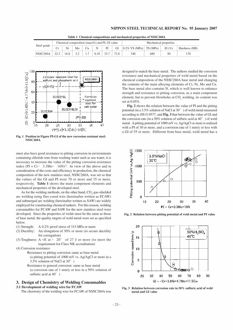
2. Guidelines for Development of New Stainless Steeland Welding Consumables for Chemical CargoTankersFig. 1 shows the target corrosion resistance set out for the
development of NSSC260A. The principal mode of corrosion ofchemical tanks in environments containing sulfuric or phosphoricacid is general corrosion. To enhance the resistance of stainless steelto general corrosion, it is necessary to increase the value of the generalcorrosion resistance index (GI =-Cr+3.6Ni+4.7Mo+11.5Cu)2).Furthermore, since stainless steel for chemical tanker applications
NIPPON STEEL TECHNICAL REPORT No. 95 January 2007
- 23 -
must also have good resistance to pitting corrosion in environmentscontaining chloride ions from washing water such as sea water, it isnecessary to increase the value of the pitting corrosion resistanceindex (PI = Cr+ 3.3Mo+ 16N)3). In view of the above and inconsideration of the costs and efficiency in production, the chemicalcomposition of the new stainless steel, NSSC260A, was set so thatthe values of the GI and PI were 70 or more and 35 or more,respectively. Table 1 shows the main component elements andmechanical properties of the developed steel.
As for the welding methods, on the other hand, CO2-gas-shielded
arc welding using flux-cored wire (hereinafter written as FCAW)and submerged arc welding (hereinafter written as SAW) are widelyemployed for constructing chemical tankers. For this reason, weldingconsumables for FCAW and SAW for the new stainless steel weredeveloped. Since the properties of welds must be the same as thoseof base metal, the quality targets of weld metal were set as specifiedbelow.(1) Strength: A 0.2% proof stress of 315 MPa or more(2) Ductility: An elongation of 30% or more (to secure ductility
for corrugation)(3) Toughness: A vE at - 20℃ of 27 J or more (to meet the
requirement for Class NK accreditation)(4) Corrosion resistance
Resistance to pitting corrosion: same as base metal(a pitting potential of 1000 mV vs. Ag/AgCl or more in a3.5% solution of NaCl at 30℃)
Resistance to general corrosion: same as base metal(a corrosion rate of 1 mm/y or less in a 50% solution ofsulfuric acid at 40℃)
3. Design of Chemistry of Welding Consumables3.1 Development of welding wire for FCAW
The chemistry of the welding wire for FCAW of NSSC260A was
designed to match the base metal. The authors studied the corrosionresistance and mechanical properties of weld metal based on thechemical composition of the NSSC260A base metal and changingthe contents of the main alloying elements of Cr, Ni, Mo and Cu.The base metal also contains N, which is well known to enhancestrength and resistance to pitting corrosion, as a main componentelement, but to prevent blowholes at CO
2 welding, its content was
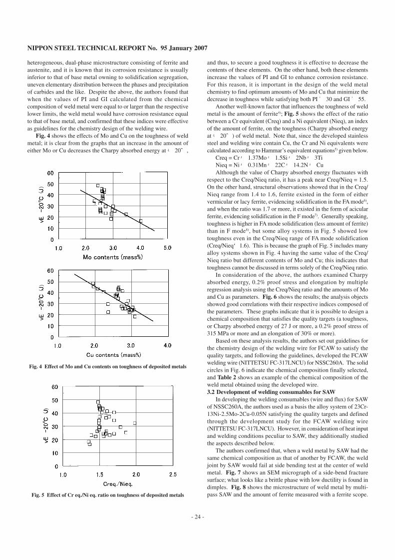
set at 0.05%.Fig. 2 shows the relation between the value of PI and the pitting
potential (in a 3.5% solution of NaCl at 30℃) of weld metal measuredaccording to JIS G 0577, and Fig. 3 that between the value of GI andthe corrosion rate (in a 50% solution of sulfuric acid at 40℃) of weldmetal. A pitting potential of 1000 mV vs. Ag/AgCl or more is realizedwith a PI of 30 or more, and a corrosion rate of 1 mm/y or less witha GI of 55 or more. Different from base metal, weld metal has a
Fig. 1 Position in Figure PI-GI of the new corrosion resistant steel:NSSC260A
Steel grade
NSSC260A
Cr
22.3
Ni
16.8
Mo
3.2
Cu
1.7
N
0.18
PI
35.7
GI
72.8
0.2% YS (MPa)
340
TS (MPa)
680
El (%)
50
Chemical composition (mass%) and PI, GI value Mechanical properties
Hardness (HB)
170
Table 1 Chemical compositions and mechanical properties of NSSC260A
(
(
Fig. 2 Relation between pitting potential of weld metal and PI value
Fig. 3 Relation between corrosion rate in 50% sulfuric acid of weldmetal and GI value
NIPPON STEEL TECHNICAL REPORT No. 95 January 2007
- 24 -
heterogeneous, dual-phase microstructure consisting of ferrite andaustenite, and it is known that its corrosion resistance is usuallyinferior to that of base metal owning to solidification segregation,uneven elementary distribution between the phases and precipitationof carbides and the like. Despite the above, the authors found thatwhen the values of PI and GI calculated from the chemicalcomposition of weld metal were equal to or larger than the respectivelower limits, the weld metal would have corrosion resistance equalto that of base metal, and confirmed that these indices were effectiveas guidelines for the chemistry design of the welding wire.
Fig. 4 shows the effects of Mo and Cu on the toughness of weldmetal; it is clear from the graphs that an increase in the amount ofeither Mo or Cu decreases the Charpy absorbed energy at - 20℃,
and thus, to secure a good toughness it is effective to decrease thecontents of these elements. On the other hand, both these elementsincrease the values of PI and GI to enhance corrosion resistance.For this reason, it is important in the design of the weld metalchemistry to find optimum amounts of Mo and Cu that minimize thedecrease in toughness while satisfying both PI≧ 30 and GI≧ 55.
Another well-known factor that influences the toughness of weldmetal is the amount of ferrite4); Fig. 5 shows the effect of the ratiobetween a Cr equivalent (Creq) and a Ni equivalent (Nieq), an indexof the amount of ferrite, on the toughness (Charpy absorbed energyat - 20℃) of weld metal. Note that, since the developed stainlesssteel and welding wire contain Cu, the Cr and Ni equivalents werecalculated according to Hammar’s equivalent equations5) given below.
Creq = Cr+ 1.37Mo+ 1.5Si+ 2Nb+ 3TiNieq = Ni+ 0.31Mn+ 22C+ 14.2N+CuAlthough the value of Charpy absorbed energy fluctuates with
respect to the Creq/Nieq ratio, it has a peak near Creq/Nieq = 1.5.On the other hand, structural observations showed that in the Creq/Nieq range from 1.4 to 1.6, ferrite existed in the form of eithervermicular or lacy ferrite, evidencing solidification in the FA mode6),and when the ratio was 1.7 or more, it existed in the form of acicularferrite, evidencing solidification in the F mode7). Generally speaking,toughness is higher in FA mode solidification (less amount of ferrite)than in F mode8), but some alloy systems in Fig. 5 showed lowtoughness even in the Creq/Nieq range of FA mode solidification(Creq/Nieq<1.6). This is because the graph of Fig. 5 includes manyalloy systems shown in Fig. 4 having the same value of the Creq/Nieq ratio but different contents of Mo and Cu; this indicates thattoughness cannot be discussed in terms solely of the Creq/Nieq ratio.
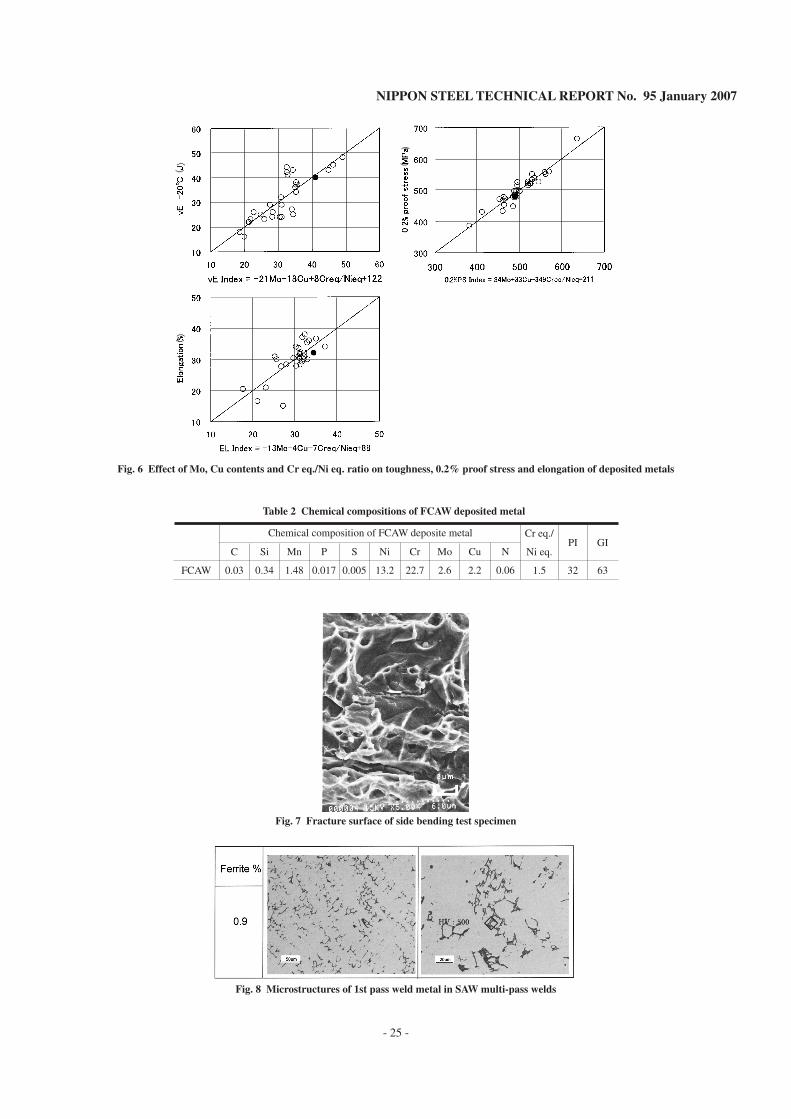
In consideration of the above, the authors examined Charpyabsorbed energy, 0.2% proof stress and elongation by multipleregression analysis using the Creq/Nieq ratio and the amounts of Moand Cu as parameters. Fig. 6 shows the results; the analysis objectsshowed good correlations with their respective indices composed ofthe parameters. These graphs indicate that it is possible to design achemical composition that satisfies the quality targets (a toughness,or Charpy absorbed energy of 27 J or more, a 0.2% proof stress of315 MPa or more and an elongation of 30% or more).
Based on these analysis results, the authors set out guidelines forthe chemistry design of the welding wire for FCAW to satisfy thequality targets, and following the guidelines, developed the FCAWwelding wire (NITTETSU FC-317LNCU) for NSSC260A. The solidcircles in Fig. 6 indicate the chemical composition finally selected,and Table 2 shows an example of the chemical composition of theweld metal obtained using the developed wire.3.2 Development of welding consumables for SAW
In developing the welding consumables (wire and flux) for SAWof NSSC260A, the authors used as a basis the alloy system of 23Cr-13Ni-2.5Mo-2Cu-0.05N satisfying the quality targets and definedthrough the development study for the FCAW welding wire(NITTETSU FC-317LNCU). However, in consideration of heat inputand welding conditions peculiar to SAW, they additionally studiedthe aspects described below.
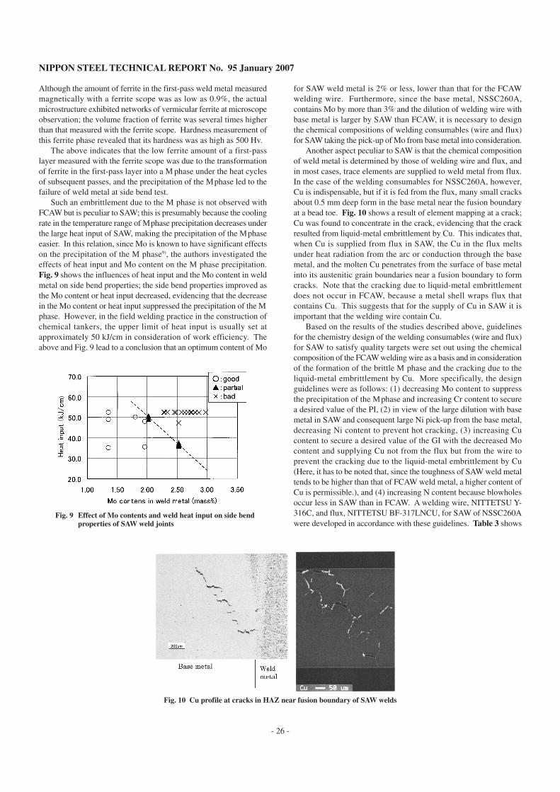
The authors confirmed that, when a weld metal by SAW had thesame chemical composition as that of another by FCAW, the weldjoint by SAW would fail at side bending test at the center of weldmetal. Fig. 7 shows an SEM micrograph of a side-bend fracturesurface; what looks like a brittle phase with low ductility is found indimples. Fig. 8 shows the microstructure of weld metal by multi-pass SAW and the amount of ferrite measured with a ferrite scope.
(
(
(
(
Fig. 4 Effect of Mo and Cu contents on toughness of deposited metals
Fig. 5 Effect of Cr eq./Ni eq. ratio on toughness of deposited metals
(
(
NIPPON STEEL TECHNICAL REPORT No. 95 January 2007
- 25 -
((
(
(
((
Fig. 6 Effect of Mo, Cu contents and Cr eq./Ni eq. ratio on toughness, 0.2% proof stress and elongation of deposited metals
Fig. 7 Fracture surface of side bending test specimen
Fig. 8 Microstructures of 1st pass weld metal in SAW multi-pass welds
Table 2 Chemical compositions of FCAW deposited metal
FCAW
C
0.03
Si
0.34
Mn
1.48
P
0.017
S
0.005
Ni
13.2
Cr
22.7
Mo
2.6
Cu
2.2
N
0.06
Cr eq./
Ni eq.
1.5
PI
32
GI
63
Chemical composition of FCAW deposite metal
NIPPON STEEL TECHNICAL REPORT No. 95 January 2007
- 26 -
Although the amount of ferrite in the first-pass weld metal measuredmagnetically with a ferrite scope was as low as 0.9%, the actualmicrostructure exhibited networks of vermicular ferrite at microscopeobservation; the volume fraction of ferrite was several times higherthan that measured with the ferrite scope. Hardness measurement ofthis ferrite phase revealed that its hardness was as high as 500 Hv.
The above indicates that the low ferrite amount of a first-passlayer measured with the ferrite scope was due to the transformationof ferrite in the first-pass layer into a σphase under the heat cyclesof subsequent passes, and the precipitation of the σphase led to thefailure of weld metal at side bend test.
Such an embrittlement due to the σ phase is not observed withFCAW but is peculiar to SAW; this is presumably because the coolingrate in the temperature range of σphase precipitation decreases underthe large heat input of SAW, making the precipitation of the σphaseeasier. In this relation, since Mo is known to have significant effectson the precipitation of the σ phase9), the authors investigated theeffects of heat input and Mo content on the σ phase precipitation.Fig. 9 shows the influences of heat input and the Mo content in weldmetal on side bend properties; the side bend properties improved asthe Mo content or heat input decreased, evidencing that the decreasein the Mo content or heat input suppressed the precipitation of the σphase. However, in the field welding practice in the construction ofchemical tankers, the upper limit of heat input is usually set atapproximately 50 kJ/cm in consideration of work efficiency. Theabove and Fig. 9 lead to a conclusion that an optimum content of Mo
for SAW weld metal is 2% or less, lower than that for the FCAWwelding wire. Furthermore, since the base metal, NSSC260A,contains Mo by more than 3% and the dilution of welding wire withbase metal is larger by SAW than FCAW, it is necessary to designthe chemical compositions of welding consumables (wire and flux)for SAW taking the pick-up of Mo from base metal into consideration.
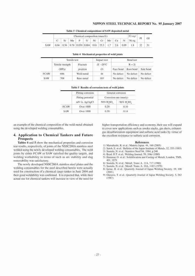
Another aspect peculiar to SAW is that the chemical compositionof weld metal is determined by those of welding wire and flux, andin most cases, trace elements are supplied to weld metal from flux.In the case of the welding consumables for NSSC260A, however,Cu is indispensable, but if it is fed from the flux, many small cracksabout 0.5 mm deep form in the base metal near the fusion boundaryat a bead toe. Fig. 10 shows a result of element mapping at a crack;Cu was found to concentrate in the crack, evidencing that the crackresulted from liquid-metal embrittlement by Cu. This indicates that,when Cu is supplied from flux in SAW, the Cu in the flux meltsunder heat radiation from the arc or conduction through the basemetal, and the molten Cu penetrates from the surface of base metalinto its austenitic grain boundaries near a fusion boundary to formcracks. Note that the cracking due to liquid-metal embrittlementdoes not occur in FCAW, because a metal shell wraps flux thatcontains Cu. This suggests that for the supply of Cu in SAW it isimportant that the welding wire contain Cu.
Based on the results of the studies described above, guidelinesfor the chemistry design of the welding consumables (wire and flux)for SAW to satisfy quality targets were set out using the chemicalcomposition of the FCAW welding wire as a basis and in considerationof the formation of the brittle σ phase and the cracking due to theliquid-metal embrittlement by Cu. More specifically, the designguidelines were as follows: (1) decreasing Mo content to suppressthe precipitation of the σphase and increasing Cr content to securea desired value of the PI, (2) in view of the large dilution with basemetal in SAW and consequent large Ni pick-up from the base metal,decreasing Ni content to prevent hot cracking, (3) increasing Cucontent to secure a desired value of the GI with the decreased Mocontent and supplying Cu not from the flux but from the wire toprevent the cracking due to the liquid-metal embrittlement by Cu(Here, it has to be noted that, since the toughness of SAW weld metaltends to be higher than that of FCAW weld metal, a higher content ofCu is permissible.), and (4) increasing N content because blowholesoccur less in SAW than in FCAW. A welding wire, NITTETSU Y-316C, and flux, NITTETSU BF-317LNCU, for SAW of NSSC260Awere developed in accordance with these guidelines. Table 3 shows
(
(
Fig. 9 Effect of Mo contents and weld heat input on side bendproperties of SAW weld joints
Fig. 10 Cu profile at cracks in HAZ near fusion boundary of SAW welds
NIPPON STEEL TECHNICAL REPORT No. 95 January 2007
- 27 -
Table 3 Chemical compositions of SAW deposited metal
SAW
C
0.04
Si
0.56
Mn
0.76
P
0.030
S
0.004
Ni
10.6
Cr
25.3
Mo
1.7
Cu
2.6
N
0.09
Cr eq./
Ni eq.
1.8
PI
32
GI
51
Chemical composition (mass%)
an example of the chemical composition of the weld metal obtainedusing the developed welding consumables.
4. Application to Chemical Tankers and FutureProspectsTables 4 and 5 show the mechanical properties and corrosion
test results, respectively, of joints of the NSSC260A stainless steelwelded using the newly developed welding consumables. The weldjoints by either FCAW or SAW satisfied the quality targets, andwelding workability in terms of such as arc stability and slagremovability was satisfactory.
The newly developed NSSC260A stainless steel plates and thewelding consumables for the steel described herein were actuallyused for construction of a chemical cargo tanker in June 2004 andtheir good weldability was confirmed. It is expected that, while theiractual use for chemical tankers will increase in view of the need for
Table 5 Results of corrosion tests of weld joints
FCAW
SAW
Tensile strength
(MPa)
696
708
Fracture
position
Weld metal
Base metal
vE –20°C
(J)
44
103
Face bend
No defect
No defect
Root bend
No defect
No defect
Side bend
No defect
No defect
Tensile test Impact test Bend test
R = 2t
Table 4 Mechanical properties of weld joints
FCAW
SAW
Pitting corrosion
Pitting potential
mV vs. Ag/AgCl
Over 1000
Over 1000
General corrosion
Corrosion rate (mm/y)
50% H2SO
4
0.20
0.39
96% H2SO
4
0.10
0.14
higher transportation efficiency and economy, their use will expandto cover new applications such as smoke stacks, gas ducts, exhaust-gas desulfurization equipment and sulfuric-acid tanks by virtue ofthe excellent resistance to sulfuric acid corrosion.
References1) Matsuhashi, R. et al.: Materia Japan. 44, 160 (2005)2) Satoh, E. et al.: Bulletin of the Japan Institute of Metals. 32, 355 (1993)3) Suutala, N. et al.: Stainless Steel’84, 1984, p.2404) Read, D.T. et al.: Welding Journal. 59, 104s (1980)5) Hammar, O. et al.: Solidification and Casting of Metals, London, TMS,
401, 19796) Suutala, N. et al.: Metall. Trans. A. 11A, 717 (1980)7) Suutala, N. et al.: Metall. Trans. A. 10A, 1183 (1979)8) Inoue, H. et al.: Quarterly Journal of Japan Welding Society. 19, 100
(2001)9) Onzawa, T. et al.: Quarterly Journal of Japan Welding Society. 5, 262
(1987)