Development of Fully Automatic Both -Side Welding (GMAW) for ...
8
Development of Fully Automatic Both - Side Welding (GMAW) for Pipeline Kenji Kitano * , Masahito Ikebe * , Hiromi Shiraishi * * , Tatsuya Kasatani * * * Sumitomo Metal Industries ,LTD. Pipeline Engineering Department 5-33,Kitahama,4-Chome,Chuo-ku,Osaka,541 JAPAN * * Sumitomo Metal Plantec CO.,LTD. Engineering Department 2Dej ima -Nishimachi , Sakai , Osaka, 590 JAPAN ABSTRACT Development of a fully automatic both-side welding method for pipeline construction was achieved in terms of combining an internal clamp and welding device with a two external head welding device. A double-V butt joint of 40 degree geometry was applied with simultaneous three head operation (one internal and two external heads), reducing the deposited area to a half and increasing the welding rate by about five times in comparison with the former 60 degree joint geometry and an external single head GMA penetration welding method. The new process also provides the method of inprocess on-line tracking of the weld line as the welding proceeds, because the optical sensor is capable of detecting the variation in parameters such as joint and deposit geometries. In addition, as the welding conditions can be properly controlled under a real time, it was achieved to stabilize the weld quality and save labor. 1. Introduction Rapid development of pipeline fluid transport in recent years has led to the slurry transportation of coal and iron ore and capsule transport as well as gas and liquid involved in long distance mass transfer of petroleum and natural gas, town gas piping, water transport lines, and local heating and cooling system lines. Further development in such field is expected to be continued in the future. -239 13th ISARC
Transcript of Development of Fully Automatic Both -Side Welding (GMAW) for ...
Development of Fully Automatic Both - Side Welding (GMAW) for Pipeline
Kenji Kitano * , Masahito Ikebe * , Hiromi Shiraishi * * , Tatsuya Kasatani * *
* Sumitomo Metal Industries ,LTD. Pipeline Engineering Department5-33,Kitahama,4-Chome,Chuo-ku,Osaka,541 JAPAN
* * Sumitomo Metal Plantec CO.,LTD. Engineering Department2Dej ima-Nishimachi , Sakai , Osaka, 590 JAPAN
ABSTRACT
Development of a fully automatic both-side welding method for pipeline
construction was achieved in terms of combining an internal clamp and welding
device with a two external head welding device. A double-V butt joint of 40
degree geometry was applied with simultaneous three head operation (one
internal and two external heads), reducing the deposited area to a half and
increasing the welding rate by about five times in comparison with the former 60
degree joint geometry and an external single head GMA penetration welding
method. The new process also provides the method of inprocess on-line
tracking of the weld line as the welding proceeds, because the optical sensor is
capable of detecting the variation in parameters such as joint and deposit
geometries. In addition, as the welding conditions can be properly controlled
under a real time, it was achieved to stabilize the weld quality and save labor.
1. Introduction
Rapid development of pipeline fluid transport in recent years has led to the slurry
transportation of coal and iron ore and capsule transport as well as gas and liquid involved
in long distance mass transfer of petroleum and natural gas, town gas piping, water
transport lines, and local heating and cooling system lines. Further development in such
field is expected to be continued in the future.
-239 13th ISARC
Development of pipelines of larger diameter and higher pressure in response to the
increasing demand for natural gas is especially noted, while an advanced technology for the
on-site girth welding which affects the quality and the cost of the pipeline is requiredbecause it is penetration welding.
In addition, since the operation has to be carried out under special circumstances
different from those in a plant, generally automation is rather left behind than in other fields,
though multiple efforts of development and application have been made.
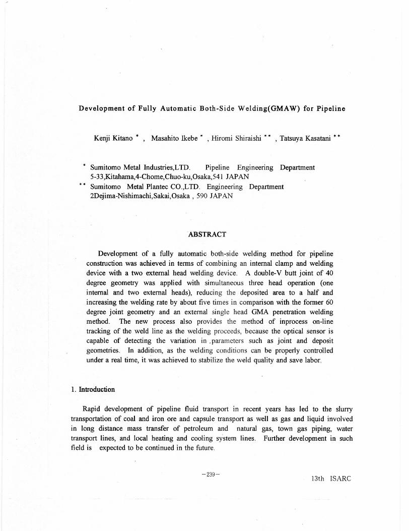
Under these circumstances, we understood improvement of the conventional automaticwelding method for pipeline and development of fully automatic both-side welding(GMAW) aimed at substantially increasing the welding speed . As it is likely to becommercialized , the outline of our research and development will be described below.Table 1 indicates the principal scope of pipe dimensions to be handled by this weldingprocess.
Table 1 Principal scope of pipe dimensions to be handled by automatic welding process
Method Steel Grade 100 500 1000 2000 O D (m m)
Penetration Welding Large Diameter GMAGas Metal
Arc Welding Carbon Steel Both-side GMA Mead)
Fillet Welding
Electrogas
EGWwelding
Gas TungstenCarbon Steel Automatic GTA
Arc WeldingStainless Steel
DiffusionAlloy Steel Amorphous Insert Metal
Bonding
2. Outline and features of welding devices
As for welding equipment, "two external head welding device" and "internal clamp and
welding device" were developed in order to use a double-V butt joint which could markedly
reduce the deposited area and bring forth stable quality.
13th ISARC -240-

2.1 Two external heads welding device
Our company used to apply a single external head to automatic welding (Fully automatic
GMA welding), and has developed a new device with two heads in order to improve theefficiency of operation.
In this device, weld line tracking has been improved to be carried out by in-process
sensing by use of an optical sensor, which enables the device to cope with multilayer
welding for thick wall and one operator to operate multiple head welding.
The weight and dimensions of the welding heads and the guide rail have been reduced
to about a half of those in conventional devices in order to shorten the time required for
setting up and dismantling the automatic welding device and also to minimize the
interference between welding heads involved with the use of a two head device.
Fig. 1 shows the configuration of devices for on-site operation. The whole system of
devices is constructed so as to be carried by a 2-ton truck including the internal clamp and
welding device to be described later in order to enhance the maneuverability in on-siteoperation.
m
cameraCCU
--------------------f><
rinta I1 , r^ I
switch BOX
monitorTV
IWDCPU
CRT
L
Her2
weldingcondition
ul
I II
I off-line CPU
Fig. 1 Configuration of devices for on-site operation
-241- 13th ISARC
WDera
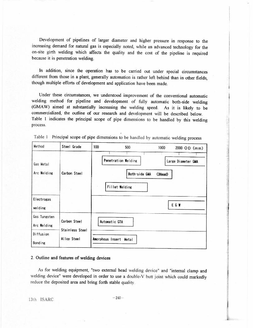
Specifications and the appearance of the device are shown
in Table 2 and Fig. 2 respectively.
Table 2 Specifications of two external
head welding device
Item Two External Head GMA Fully Automatic GMA
Con- Welding Head 2 Heads 1 Head
troller Mode Adaptive Control Feedback Control
Tracking ofWeld Line
Inprocess sensing(Optical Sensor )
In advance(Contact Sensor)
Welding Condition Off-line Device Off-line Device
Welding Head 2 Heads / Rail(1 Torch/ 1 Head)
1 Head /Rail(1 Torch/ 1 Head)
Rail Traveling Rack and Pinion Rack and Pinion(Original Car Track)
Setting Cam Bolt Joint
11111111Fig.2 Appearance of two
external head welding device
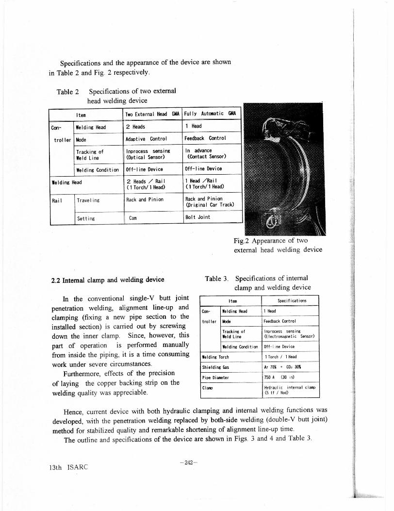
2.2 Internal clamp and welding device
In the conventional single-V butt joint
penetration welding, alignment line-up and
clamping (fixing a new pipe section to the
installed section) is carried out by screwing
down the inner clamp. Since, however, this
part of operation is performed manually
from inside the piping, it is a time consuming
work under severe circumstances.
Furthermore, effects of the precision
of laying the copper backing strip on the
welding quality was appreciable.
Table 3. Specifications of internal
clamp and welding device
Item Specifications
Con- Welding Head 1 Head
troller Mode Feedback Control
Tracking ofWeld Line
Inprocess sensing(Electromagnetic Sensor)
Welding Condition Off- line Device
Welding Torch 1 Torch / I Head
Shielding Gas Ar 70% + C0z 30%
Pipe Diameter 750 A (30 in)
Clamp Hydraulic internal clamp(5 tf / Rod)
Hence, current device with both hydraulic clamping and internal welding functions was
developed, with the penetration welding replaced by both-side welding (double-V butt joint)
method for stabilized quality and remarkable shortening of alignment line-up time.
The outline and specifications of the device are shown in Figs. 3 and 4 and Table 3.
-242-13th ISARC
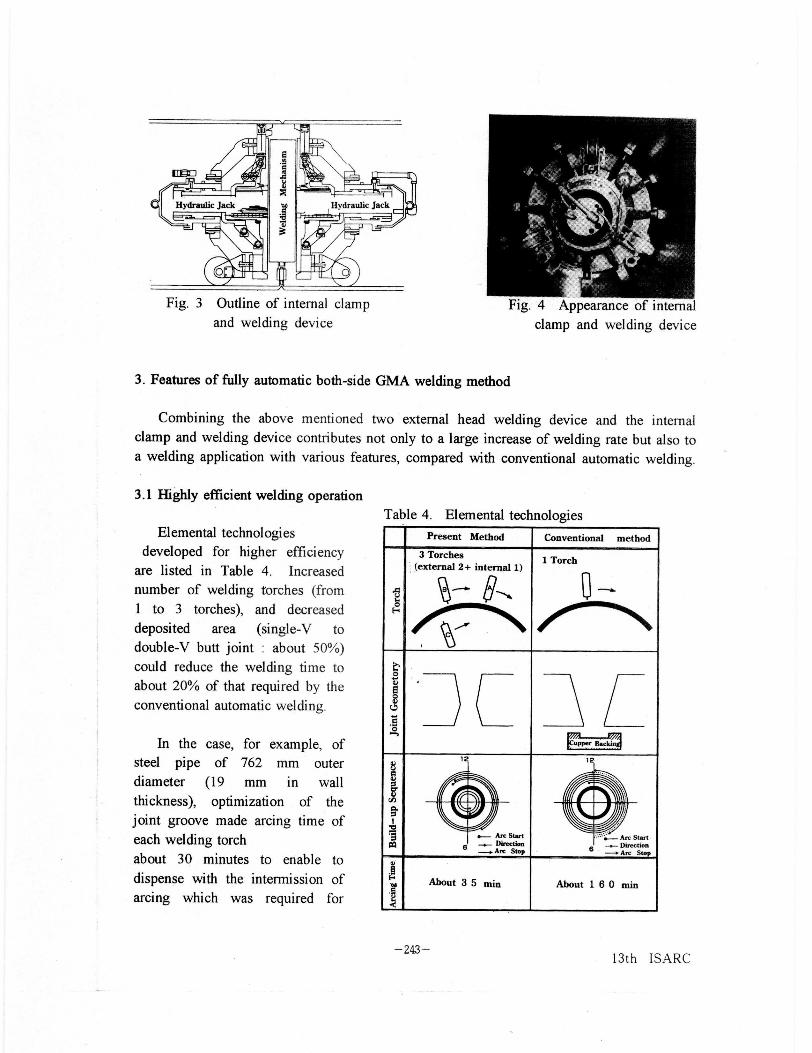
Fig. 3 Outline of internal clamp
and welding device
aFig. 4 Appearance of internal
clamp and welding device
3. Features of fully automatic both-side GMA welding method
Combining the above mentioned two external head welding device and the internal
clamp and welding device contributes not only to a large increase of welding rate but also to
a welding application with various features, compared with conventional automatic welding.
3.1 Highly efficient welding operation
Elemental technologies
developed for higher efficiency
are listed in Table 4. Increased
number of welding torches (from
1 to 3 torches), and decreased
deposited area (single-V to
double-V butt joint : about 50%)
could reduce the welding time to
about 20% of that required by the
conventional automatic welding.
In the case , for example, ofsteel pipe of 762 mm outerdiameter (19 mm in wallthickness), optimization of thejoint groove made arcing time of
each welding torch
about 30 minutes to enable to
dispense with the intermission of
arcing which was required for
Table 4. Elemental technologies
Present Method Conventional method
3 Torches(external 2+ internal 1)
1 Torch
0v0
:J E La.5upper 11.ai
U
av
1 ,2
yIb
CQ
Arc Start8 Direction
-^ Arc Stop
6 Arc Start..- Direction
-c Arc Stop
v
About 3 5 min About 1 6 0 min
-243-13th ISARC
cleaning the nozzles during welding , thus reducing the welding time.
Table 5 shows the arcing time of each welding head for a steel pipe of 762 mm in outer
diameter and 19mm in wall thickness (API-5L-X65).
It took about
35 minutes from
the arcing start of
the internal head
to the completion
of the external
welding.
Table 5 Arcing time of each welding head ( 0 762 X t19)
timehead
5 10 15 20 25 30 35 40 (min)
external (24) jJ 'head A 11 ' 5)(2035
head B.
12.5' 33
internal (27) 27'head C
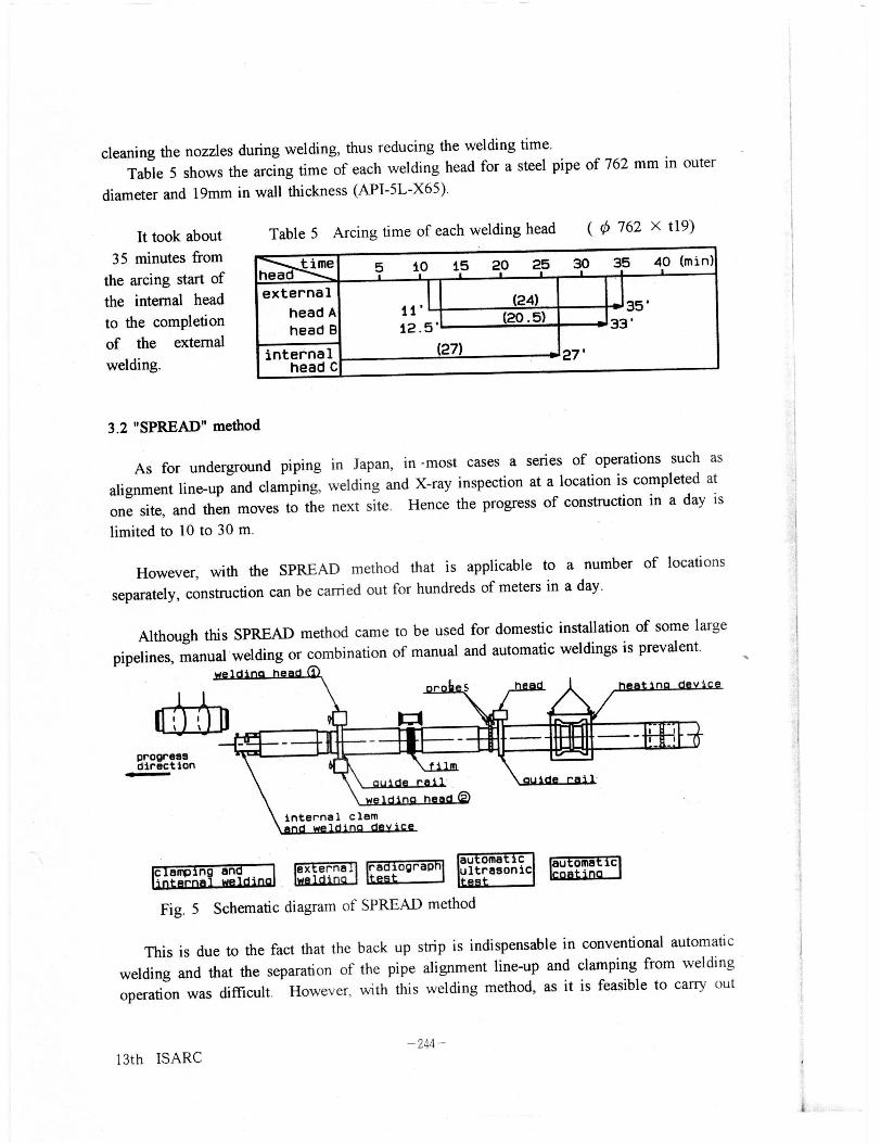
3.2 "SPREAD" method
As for underground piping in Japan , in most cases a series of operations such as
alignment line-up and clamping, welding and X-ray inspection at a location is completed at
one site , and then moves to the next site . Hence the progress of construction in a day is
limited to 10 to 30 m.
However, with the SPREAD method that is applicable to a number of locations
separately, construction can be carried out for hundreds of meters in a day.
Although this SPREAD method came to be used for domestic installation of some large
pipelines, manual welding or combination of manual and automatic weldings is prevalent.
welding head n
progressdirection
c amp ng an ex erne ra iograpLWILL-i
aut oma ti cultrasonictL-At
au oma is
Fig. 5 Schematic diagram of SPREAD method
This is due to the fact that the back up strip is indispensable in conventional automatic
welding and that the separation of the pipe alignment line-up and clamping from welding
operation was difficult. However, with this welding method, as it is feasible to carry out
- 244-13th ISARC

the internal welding immediately after the alignment line up and clamping operation, the
external welding can be conducted at any time, which makes the SPREAD method with
efficient and fully automatic welding applicable. The concept of the procedure is shown in
Fig. 5.
3.3 Control of optimized welding conditions
In conventional fully automatic welding, a contact sensor was used for weld line
tracking in advance, hence all the weld line data in memory were reproduced for tracking
the weld line.
In addition, the welding
condition was fixed as prepared
beforehand on the basis of the
standard joint geometry, hence
highly precise alignment line-up and
joint geometry were required.
Points of detecting the joint
geometry and a comparison of
welding procedures are shown in
Fig. 6 and Fig.7 respectively.
(Conventional Method]
Alignment Line-up and Clamping(Screwing Down Inner Clamp)
ISetting Copper Backing
I
Setting External Welding Device
I I-----------------_-. ----------------
weld line (tracking X. Y)points of detecting
joint geometry and weaving widthweld bead form
welding speed
Fig. 6 Points of detecting joint geometry
( Present Method )
Alignment Line-up and.Clamping(Hydraulic Clamping)
Setting External Welding Device
IL
Detecting of Weld Line
External Welding
Welding Condition : Fixed Data(IC CARD)
Tracking of Weld line : Playback
Internal Head AExternal Welding
Welding Welding
K
Head BbWelding
K
Welding Condition : VariableBead ,Joint: Detecting on Real Time
Fig.7 Comparison of welding procedures
-245- 13th ISARC

Since by the present method the welding condition is variable and the weld line tracking
is performed as the changing weld bead form and joint geometry are detected on real time
while welding proceeds, the work can be fully carried out with the same accuracy of joint
geometry as with manual welding.
3.4 Joint characteristics
Nondestructive testing such as radiographic examination as well as characterization by
tensile tests, bend tests and Charpy impact testing demonstrated that the present weld
joint has equivalent joint characteristics to those obtained by conventional automatic
welding.
4. Conclusion
It is not too much to say that the performance and the construction cost of a pipeline
depend on the on-site welding method of joints. Therefore further efforts will be made for
development of a fully automatic welding method in order to enhance the process efficiency
as well as stable quality.
-246-13th ISARC