
DESIGNING AND IMPLEMENTING THE CONTROL SYSTEM …
76
LAPPEENRANTA UNIVERSITY OF TECHNOLOGY LUT School of Energy Department of Electrical Engineering Jani Alho DESIGNING AND IMPLEMENTING THE CONTROL SYSTEM SOFTWARE FOR A HYBRID CITY BUS PROTOTYPE Examiners: Professor, D.Sc. (Tech) Olli Pyrhönen Associate professor, D.Sc. (Tech) Tuomo Lindh Supervisor: Associate professor, D.Sc. (Tech) Tuomo Lindh
Transcript of DESIGNING AND IMPLEMENTING THE CONTROL SYSTEM …

LAPPEENRANTA UNIVERSITY OF TECHNOLOGY
LUT School of Energy
Department of Electrical Engineering
Jani Alho
DESIGNING AND IMPLEMENTING THE CONTROL SYSTEM
SOFTWARE FOR A HYBRID CITY BUS PROTOTYPE
Examiners: Professor, D.Sc. (Tech) Olli Pyrhönen
Associate professor, D.Sc. (Tech) Tuomo Lindh
Supervisor: Associate professor, D.Sc. (Tech) Tuomo Lindh
TIIVISTELMÄ
Lappeenrannan teknillinen yliopisto Teknillinen tiedekunta Sähkötekniikan koulutusohjelma Jani Alho Prototyyppihybridilinja-auton ohjausjärjestelmän ohjelmallinen suunnittelu ja toteutus
2016
Diplomityö. 76 sivua, 18 kuvaa, 2 taulukkoa, 3 liitettä.
Tarkastajat: Professori, TkT Olli Pyrhönen Tutkijaopettaja, TkT Tuomo Lindh
Ohjaaja: Tutkijaopettaja, TkT Tuomo Lindh
Hakusanat: autotekniikka, linja-autot, hybridiautot, ohjelmoitavat logiikat, testaus, riskinhallinta, turvallisuus
Keywords: automotive engineering, buses, hybrid electric vehicles, programmable logic controllers, testing, risk management, safety
Nykyiset ympäristösuuntaukset vauhdittavat ekologisempien ja vähemmän saastuttavien
ajoneuvojen kehittämistä. Ajoneuvojen ja lyhyillä työsykleillä toimivien työkoneiden
hybridisointi on osoittautunut tehokkaaksi tavaksi vähentää polttoaineenkulutusta ja
päästöjä. Kaupallisessa mielessä uudet teknologiat ottavat vielä ensiaskeleitaan
valmistajien kehittäessä ja kokeillessa erilaisia teknisiä ratkaisuja.
Uudenlaisen tekniikan jälkiasentaminen vanhempiin ajoneuvoihin saattaisi jatkaa niiden
käyttöikää. Lappeenrannan teknillinen yliopisto on rakentanut vanhemmasta
kaupunkilinja-autosta sarja-rinnakkaishybridin. Meneillään oleva tutkimus pyrkii
selvittämään, voitaisiinko tämänkaltainen jälkiasennus tehdä kaupallisesti kannattavaksi.
Tämän työn tarkoituksena oli kehittää hybridin ohjausjärjestelmää varten ohjelmisto, joka
on riittävän turvallinen julkiseen käyttöön ja pystyy tuottamaan mittaustietoa tutkimusta
varten. Tämä työ kuvaa kehitysprojektin ydin- ja tukiprosessit sekä esittelee niiden eri
vaiheisiin liittyviä menetelmiä, muun muassa riskienhallintaa ja testausta. Rajallisista
henkilöresursseista riippumatta projekti kykeni osoittamaan, että pienemmissäkin
prototyyppiprojekteissa voidaan saavuttaa tyydyttäviä tuloksia soveltamalla mukautettuja
teollisuusstandardien mukaisia menetelmiä. Työn johtopäätös on, että aktiivinen
projektinhallinta ja järjestelmälliset suunnittelumenetelmät ovat avain monitahoisen
projektin onnistumiseen.

ABSTRACT
Lappeenranta University of Technology Faculty of Technology Degree Programme in Electrical Engineering Jani Alho Designing and implementing the control system software for a hybrid city bus prototype
2016
Master’s Thesis. 76 pages, 18 pictures, 2 tables, 3 appendices.
Examiners: Professor, D.Sc. (Tech) Olli Pyrhönen Associate professor, D.Sc. (Tech) Tuomo Lindh
Supervisor: Associate professor, D.Sc. (Tech) Tuomo Lindh
Keywords: automotive engineering, buses, hybrid electric vehicles, programmable logic controllers, testing, risk management, safety
Hakusanat: autotekniikka, linja-autot, hybridiautot, ohjelmoitavat logiikat, testaus, riskinhallinta, turvallisuus
Current environmental trends are pushing the development of more ecological and less
polluting vehicles. Hybridization of vehicles and heavy-duty machinery with short duty
cycles has already proved to be an effective way to cut down fuel consumption and
emissions. The new technologies are still taking their first steps commercially, and the
manufacturers are developing and testing different solutions.
Retrofitting new technologies into older commercial vehicles could be one solution to
extend their lifespan. Lappeenranta University of Technology has equipped an older city
bus with equipment capable of series-parallel hybrid operation. On-going research is
trying to establish whether this kind of retrofitting could be made commercially viable.
The aim of this work was to develop hybrid control system software ensuring safe public
operation and capable of providing measurement data for research purposes. This work
essentially describes the core management process and its support processes. It explains
some basic methodology for each phase of this engineering project, covering for example
risk management and testing. Despite limited human resources, the project demonstrates
that industrial standards methods can successfully be scaled down, used in a small-size
prototype project and provide satisfactory results. The work concludes that active project
management and structured design methods are key factors in successfully completing a
project with such complexity.

ACKNOWLEDGEMENTS
This master's thesis was carried out at Lappeenranta University of Technology (LUT) in
the Department of Electric Engineering as a part of a hybrid city bus project named
CAMBUS.
I would like to thank Professors Olli and Juha Pyrhönen for the opportunity to participate in
the project. In addition, I want to express my profound gratefulness to Associate professor
Tuomo Lindh for the supervision of this work, and for all the support and guidance
throughout. I would also like to thank all the CAMBUS project associates and colleagues
for their ideas and collaboration. It sure has been an interesting and educational journey.
During the project, I also had the chance to meet some of the most amazing people
working in the automotive sector. Especially Juhani Tikkanen deserves my humble
gratitude. Thank you for all your ideas and support.
My sincerest gratitude goes to my parents for all their support during these years; and
finally, I’d like to send warm thanks to all my friends. We have spent countless hours
talking and reasoning, always learning something new together. Never get weary.
Jani Alho
November 2016
Lappeenranta, Finland

TABLE OF CONTENTS
1 INTRODUCTION ............................................................................................................. 8
1.1 Goals ..................................................................................................................... 10
1.2 Scope ..................................................................................................................... 11
1.3 Terminology ........................................................................................................... 11
1.4 The structure of this document ............................................................................... 12
1.5 The core process ................................................................................................... 12
1.6 About the preselected equipment ........................................................................... 14
2 THE DESIGN REQUIREMENTS ................................................................................... 17
2.1 Legal requirements ................................................................................................ 18
2.1.1 Electrical safety and electromagnetic compatibility .......................................... 19
2.1.2 Requirements per UNECE R100 ..................................................................... 20
2.1.3 Service brake and steering .............................................................................. 20
2.2 Risk management .................................................................................................. 21
2.2.1 Risk analysis ................................................................................................... 23
2.2.2 Risk reduction ................................................................................................. 23
2.3 Typical risks ........................................................................................................... 25
2.4 Functional safety of the control equipment ............................................................. 26
3 THE SYSTEM AND SOFTWARE DESIGN ................................................................... 29
3.1 Logical system architecture .................................................................................... 29
3.2 Technical system architecture ................................................................................ 30
3.3 System safety architecture ..................................................................................... 33
3.4 Safety aspects of the software project management .............................................. 36
3.5 Software architecture ............................................................................................. 37
3.6 Monitoring functions and diagnostics ...................................................................... 40
4 THE TESTING PROCESS ............................................................................................ 42
4.1 Software test principles .......................................................................................... 43
4.2 Software test methods............................................................................................ 43
4.3 Module testing ........................................................................................................ 45
4.4 Integration tests...................................................................................................... 45
4.5 Validation tests and commissioning........................................................................ 46
5 RESULTS ..................................................................................................................... 47
5.1 Results of the software process ............................................................................. 47
5.2 Validation and real-life tests ................................................................................... 49
5.3 Case example: The accelerator .............................................................................. 49
5.3.1 Accelerator design requirements ..................................................................... 50
5.3.2 Functional safety requirements for the accelerator .......................................... 51
5.3.3 Software implementation of the accelerator..................................................... 52
5.3.4 Accelerator fault diagnosis .............................................................................. 55
5.3.5 Accelerator safety ........................................................................................... 57
6 DISCUSSION ................................................................................................................ 60
6.1 Instrumentation ...................................................................................................... 60
6.2 Safety aspects of the chosen equipment ................................................................ 61
6.3 Signal diagnostics .................................................................................................. 61
6.4 Traction-motor-related problems ............................................................................ 63
6.5 Project management issues ................................................................................... 64
REFERENCES ..................................................................................................................... 66
APPENDICES
I. Risk assessment related examples
II. Program structure
III. Test case presentation
LIST OF ABBREVIATIONS
ALARP As low as reasonably possible
AC Alternating current
BMS Battery Management System
CAN Controller Area Network
CFC Continuous Function Chart
DC Direct current
ECU Electronic Control Unit
EDC Electronic Diesel Control
EMC Electromagnetic compatibility
EMI Electromagnetic interference
EUC Equipment under control
EUT Equipment under test
EV Electric Vehicle
FO Fail-operational
FR Fail-reduced
FS Fail-safe
FSM Finite State Machine
HCU Hybrid Control Unit
HEV Hybrid Electric Vehicle
HV High voltage
ICE Internal combustion engine
IEC International Electrotechnical Commission
ISO International Organization for Standardization
LV Low voltage
PLC Programmable Logic Controller (in relation to physical devices)
RESS Rechargeable energy storage system
SIL Safety Integrity Level
SRE Safety Related Equipment
ST Structured Text
UNECE United Nations Economic Commission for Europe
VECU Vehicle electrics and electronics control unit
8
1 INTRODUCTION
While the electrification of vehicle powertrains seems to be a fast growing trend, the slow
development of rechargeable energy storage systems (RESS) is still holding back the
rapid spread of electric vehicles (EV). One of the main disadvantages is the RESS
operational range. To extend the range one would need a bigger battery, which in turn
brings in more weight and wastes space. In cold environments, the battery power would
be reduced dramatically without a pre-heating system, which in turns adds to the overall
energy consumption.
A hybrid electric vehicle (HEV) can help to combine the best properties of both electric
drives and the internal combustion engine (ICE). The hybrid is not fully dependent on the
limited electric power storage. The idea is to combine two power sources to overcome to
shortcomings of either of these technologies used on their own. (Reif et al. 2014, 724)
There are common hybrid configurations and new innovative solutions are being tested. In
a series hybrid, electric power is generated using an internal combustion engine to drive a
generator and the powertrain itself is operated with an electrical drive. In a parallel hybrid
configuration, both power sources can be operated simultaneously to drive the powertrain
and a generator operation of the internal combustion engine is possible. This solution
requires a transmission or other power line strategy because of the internal combustion
engine and its limitations. In order to combine these two technologies in one vehicle, all
components of both systems are required, and they can be linked together by a
mechanical clutch. This is called the series-parallel hybrid. It enables independent series
and parallel operation, and combined operation with two electrical machines. A power-split
hybrid also combines series and parallel operation using a planetary-gear transmission
instead. The Toyota Prius utilizes this kind of technology. The adverse effect of the
increased weight in series-parallel hybrid would not always be tolerable in a small vehicle,
but the concept might be usable in a heavy commercial vehicle. (Reif et al. 2014, 727-732;
Immonen et al. 2012)
In designing a hybrid system, it is very important to observe the conditions of use and duty
cycle of the vehicle. Some vehicles with an internal combustion engine can be rather
effective, for example, an intercity bus that is driving long distances between stops, whose
engine runs on high efficiency during travel. However, energy efficiency of a similar
configuration in city bus use would not be very desirable. Constant stopping and
accelerating consumes considerable energy, and the internal combustion engine load
9
does not permit the engine to operate within the range of best efficiency. The energy
efficiency during acceleration from stop with an electric drive generally has more than
twice the efficiency of a comparable internal combustion engine with a separate
transmission (Immonen et al. 2012). A fully electrically operated bus would require
charging from an external network and preferably, the charging should be done rapidly in
order for the bus to operate without long interruptions. However, the investment costs of
an opportunity-charging infrastructure may be high and limit the variety of vehicles
compatible with the chosen charging system.
Combining series and parallel hybrid technologies would allow boosting the overall
efficiency of a bus to a new level (Immonen et al. 2012). In spite of discarding the external
charging equipment and adding more freedom, the use of a more compact battery would
compensate for the added vehicle weight of the engine and generator, and it would still be
possible to drive emission-free in selected regions.
The CAMBUS idea was to create a series-parallel hybrid powertrain, which combines a
diesel engine with a greatly reduced displacement, and an electric drive capable of
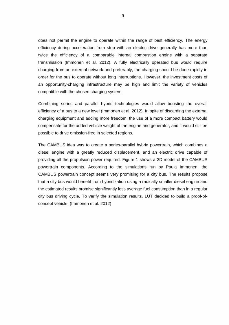
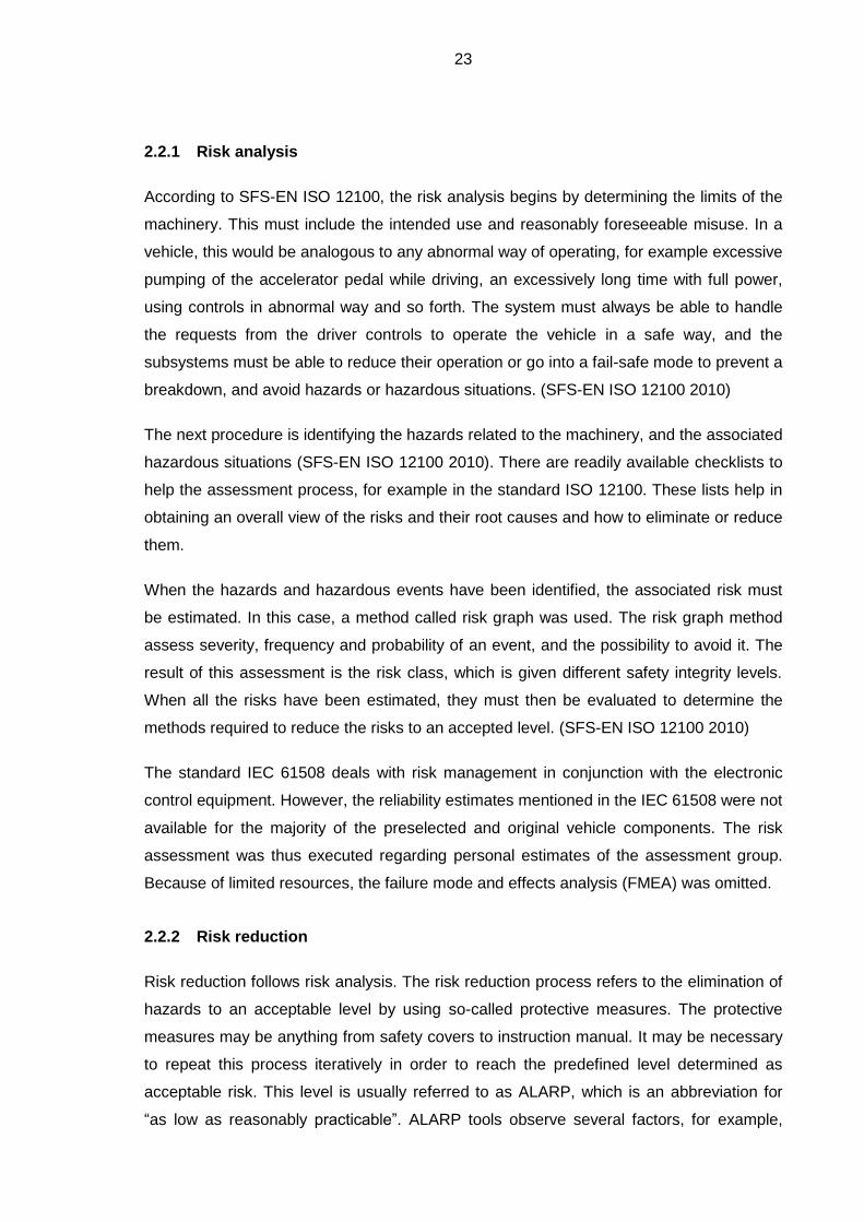
providing all the propulsion power required. Figure 1 shows a 3D model of the CAMBUS
powertrain components. According to the simulations run by Paula Immonen, the
CAMBUS powertrain concept seems very promising for a city bus. The results propose
that a city bus would benefit from hybridization using a radically smaller diesel engine and
the estimated results promise significantly less average fuel consumption than in a regular
city bus driving cycle. To verify the simulation results, LUT decided to build a proof-of-
concept vehicle. (Immonen et al. 2012)
10
Figure 1. A 3D-model of CAMBUS powertrain. (Teemu Sairanen, CAMBUS project)
LUT has declared itself as a green university, supporting the ideas of recycling and
pursuing energy efficiency. A retired city bus was chosen as the basis of the new hybrid
technology. Soon the powertrain technology was being planned.
1.1 Goals
This work was an engineering subproject for the CAMBUS main control system
development project. The aim was to design and implement software for a control system
and use structured methods of testing to demonstrate that the system is safe enough for
public driving and taking passengers. During the progress of this work, the user
requirements had to be assessed several times, as in the beginning it was somewhat
unclear what would be the final use of the bus. Some stakeholders wanted the bus to
operate independently in regular commuter traffic; some wanted the bus to remain a
proof-of-concept operated only by researchers. These decisions, of course, have great
impact on the design requirements.
This document will cover the control system, mainly from the perspective of software
development, and the forming of the main engineering processes that start from the user
requirements and end with a tested, ready-to-run prototype. The main milestone was to
get the vehicle registered as a series-parallel hybrid, enabling both the series and parallel

11
modes, and to be able to operate it on public roads, thus allowing us to focus on
calibrating the hybrid control software and achieve real-life measurement data from the
use cycles.
The work will present methods for the design process and the results of this project. It will
study some industrial design and risk reduction methods to see whether they can be
scaled down and implemented effectively with a relatively small organization, for example
a research team. It will also suggest enhancements for the future development of the
system.
1.2 Scope
The writer was not restricted to one specific role in the project but instead was acting at
almost every level of project organization. The main importance of this work was in
organizing the control system development project, creating a structured way of
proceeding in an automotive project and, as the final goal, to ensure the safe operation of
the bus after its commissioning. The whole CAMBUS project was highly ambitious for the
first automotive project of this scale at LUT.
Some of the designed software functions have yet to be implemented and will not be
completed during the time allocated for this work. This, of course, limits the scope of this
work.
The technical system architecture was planned only regarding the automation, but was
sketched to provide an adequate plan for the later testing phase. The implementation of
the automation covers the requirements defined by the risk assessment process. As for
the testing, the final validation testing is not covered by any other means than planning
some of the test procedures.
The technical capabilities and suitability of the pre-selected equipment and engineered
systems were not evaluated, only their basic functionality is covered by the test plans
created.
1.3 Terminology
Automotive terminology can sometimes be problematic. The writer has tried to adhere
mainly to the terminology of regulation 100 given by the United Nations Economic
Commission for Europe (UNECE), later referred to as ECE-R100. This text primarily uses
12
the terminology of the ECE-R100 2012, if not mentioned otherwise. However, a careful
reader would notice that even the original UNECE publications have some contradicting
terminology and abbreviations.
The automotive legislation, compared with the European Union Low Voltage Directive,
has a different approach to defining high voltage. According to ECE-R100 a voltage of
60…1500 VDC or 30…1000 VAC is declared high voltage (UNECE 1997). Again, in this
text the ECE-R100 definitions are used exclusively. In this document, the high voltage
system is referred to as HV, sometimes in conjunction with AC or DC referring to the type
of current in question. Similarly, the 12 or 24 volt systems are referred to with the
abbreviation LV, low voltage. In accordance to the terminology of the regulation, the term
isolation resistance is used instead of insulation resistance.
1.4 The structure of this document
The design process will be examined in more detail after the introduction (Chapter 1). The
text uses actual project-related information as examples to enlighten the meaning of the
processes. Section 1.6 looks at the process of gathering the design requirements,
including risk analysis, and the main safety concepts and considerations. Chapter 3 then
discusses the logical system architecture, from which the technical architecture solution is
formed. The software design process is then described in more detail.
When implementation is complete, Chapter 4 will enlighten the reader on the methods of
testing used during the validation process. Subsequently, in section 3 of chapter 5, we
shall take a case example of the implementation of the accelerator pedal and the safety
features related therein. The next section explains the immediate results from the different
phases of the process. Finally, chapter 6 will express the writer’s subjective thoughts on
the project in the discussion.
1.5 The core process
The nature of this work is systems engineering rather than scientific research. The writer
chose to follow the structured methods suggested by Jörg Schäuffele and Thomas
Zurawka as the basic guideline for the project. It is an interpretation of the common V-
model (essentially the same as in ISO/IEC 12207 and ISO 26262), taking into account the
requirements for an automotive software project, its methods and relevant safety
standards. Various standards were used for further guidance and they will be introduced

13
later in the text. Because the project did not design or manufacture any electronic devices,
the model is used to guide the design and implementation of the software and system
levels. Figure 2 represents the core process of this project. Each box of the figure
presents a sub-process explained in more detail in the relevant chapters of this document.
Analyze requirements --------------------------------------
Specification of the logical system architecture
Analyze logical system architecture
-----------------------------------Specification of the
technical system architecture
Analyze software requirements
--------------------------------- Specification of the
software architecture
Specify software components
Design and implement the software components
Test of the software components
Integration of software components
Integration test of the software
Integration of the system components
Integration test of the system
Calibration
Acceptance test----------------------------------
System test
Systemdevelopment
Softwaredevelopment
func1
func3
func2
func4
ECU1
ECU3
ECU2
Figure 2. Overview of the core process for the development of electronic systems and
software. (copied according to Schäuffele et al.) (Schäuffele et al. 2013)
The left half of the V is explained in chapter 3. The first step of this model begins by the
determination of the user requirements, from which a logical operating plan for the system
is created. At the next level, the equipment capable of executing and materializing all
these logical operations are chosen or designed. This level is called the technical system
architecture. Finally, the software architecture is planned according to the requirements
set by the technical system architecture and the properties of the chosen equipment.
(Schäuffele et al. 2013)
In contrast, testing follows an opposite path, where first the software functions and
modules are tested. When the individual components work according to the plan, they are
being integrated and thus the system is tested for the first time as a whole. When
everything works as expected, the process will move to fine-tuning the system, to

14
thorough use tests in actual environments, and finally to an acceptance test to prove that
all the requirements have been fulfilled. Chapter 4 presents the testing process.
(Schäuffele et al. 2013)
Some new matters could appear during the process, introducing new risks or
requirements, and then all levels of the plan must be updated accordingly. Thus, it is very
important to spend some time in the beginning to build a good foundation through
thorough planning. The more experienced the design team, the more thorough the plan,
which will minimize unnecessary iterations at a later stage. Safety is one of the main
concerns, and as for the planning, it would be beneficial to have a safety-oriented way of
thinking throughout the process. (Schäuffele et al. 2013)
1.6 About the preselected equipment
The basis vehicle is a 1997 Volvo B10BLE Säffle city bus. Its engine compartment had a
small fire hazard, but the original project team came up with an ambitious plan to resurrect
the vehicle with new high tech equipment. Its engine and transmission were removed and
the car was acquired almost free-of-charge. The simulations had already given direction to
the requirements for the engine power, as well as battery capacity and generator power.
It was not possible to fully follow the V-model process as some of the equipment was
already chosen. With a thorough user-requirements study and a thorough study of the
available technical solutions, different choices could have been made. The management
of the automation project had already decided to use ABB AC500 XC series
programmable logic controller (PLC) devices for the control system prototype. It was later
understood that they do not fully comply with common automotive design
recommendations, but they allow flexible prototyping and programming.
The programming environment consist of the ABB provided Control Builder, which
combines the PLC configuration utility and Codesys development environment. The
Control Builder software manages hardware configurations, for example input maps and
CAN bus communication buffers, and links the relevant variables and ABB software
libraries directly to the Codesys environment. Codesys implements the languages defined
in the standard IEC 61131-3, which defines the programming languages for
programmable controllers. The standard includes both graphical and text-oriented
programming possibilities. The Codesys software allows online debugging, controlling and
monitoring of the PLC units over the Ethernet network of the vehicle.

15
It was decided early on, that there would be two controllers because of the long distances
within the vehicle: one in the front and one in the back of the vehicle. After the first
sketches, their functionality would be quite obvious already. As the front unit would handle
all the driver related and most of the chassis related inputs and outputs, it was named the
“vehicle electrics control unit” or VECU, and as the rear one would handle basically all of
the hybrid system components, it was named “hybrid control unit” or HCU. The network
topology of the equipment was planned as an assignment in a system engineering project
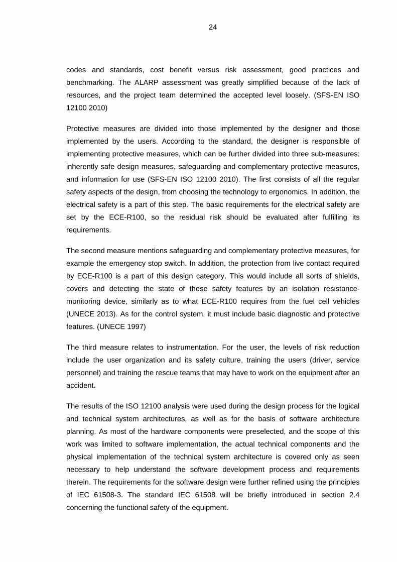
work course. Figure 3 shows an overview of the system topology. As we can see from the
picture, there are several features related to the vehicle electrics, mainly made by Volvo
and the body manufacturer Säffle, but also the control units for the Wabco Anti-locking
Brake System (ABS), including Anti-Slip Regulation (ASR) functionality, and Bosch
Electronic Controlled Suspension (ECS).
Figure 3. A simplified model of the system topology and the network buses.
There are automotive control units available that also support IEC 61131-3 programming
and likely the system programs could be ported to this platform with reasonable effort. The
current software solutions are explained in detail in section 5 of chapter 3.
At the time the equipment was selected, inverters designed for automotive applications
were not easily available. Visedo PowerMASTER inverters were chosen because they
fulfilled the environmental requirements, they have versatile internal application
programmability and are capable of driving a six-coil traction motor with two parallel
inverters. A third inverter of the same product family is used for operating the generator.
There is also a combined inverter and DC/DC converter to operate the air compressor
motor (HV) and to supply the 24 V DC (LV) system. These inverters support the user
applications created in an IEC 61131-3 compliant programming environment. One
driver interpre-
tation, pedals
HCUVECU
ABS, ECS ...
doors, lights
instruments,
switches
PC interface
battery unit,
charge control
drive
inverters
ECU
diesel engine
clutch
unit
hydraulics,
pneumatics,
cooling etc
Ethernet
16
additional auxiliary drive inverter for the motor of power steering hydraulic pump is from
ABB.
The battery system consists of lithium-titanate cells and a management system
manufactured by Altairnano. A Bender isolation monitoring device designed for
automotive applications was chosen to be incorporated into the BMS and control system
safety functions.
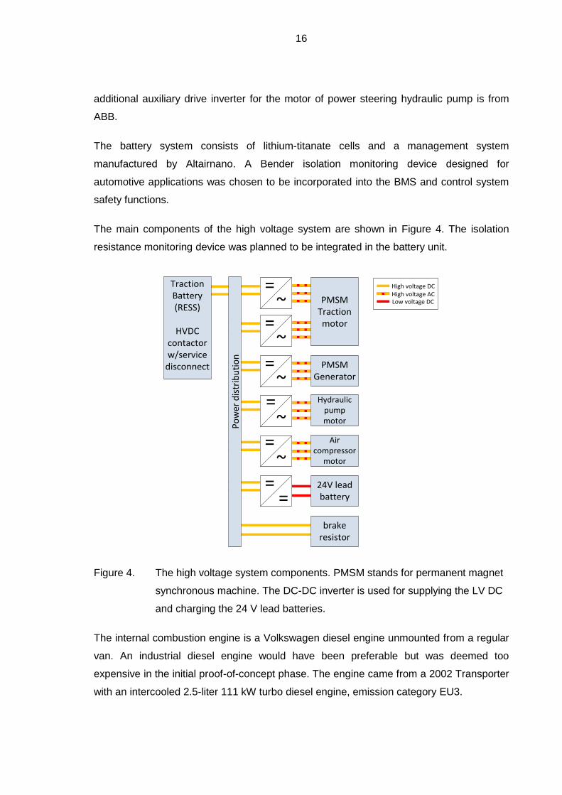
The main components of the high voltage system are shown in Figure 4. The isolation
resistance monitoring device was planned to be integrated in the battery unit.
Po
wer
dis
trib
uti
on
~
==
=~
=~
= High voltage DCHigh voltage ACLow voltage DC
TractionBattery(RESS)
HVDC contactorw/service
disconnect
24V lead battery
PMSMTraction motor
PMSMGenerator
~
Hydraulic pump motor
~
Air compressor
motor
=
=
brake resistor
Figure 4. The high voltage system components. PMSM stands for permanent magnet
synchronous machine. The DC-DC inverter is used for supplying the LV DC
and charging the 24 V lead batteries.
The internal combustion engine is a Volkswagen diesel engine unmounted from a regular
van. An industrial diesel engine would have been preferable but was deemed too
expensive in the initial proof-of-concept phase. The engine came from a 2002 Transporter
with an intercooled 2.5-liter 111 kW turbo diesel engine, emission category EU3.
17
2 THE DESIGN REQUIREMENTS
This chapter will deal with the initial function development, which includes the gathering of
the design requirements for the system. Each section represent a chronological step in
selecting the final design requirements.
As the vehicle was destined to road use, we shall first look at the legal requirements that
will be the foundation for the rest of the user requirements. Then we shall cover the
process of selecting the user requirements for the design process. These requirements
require technical solutions that lead us to the risk assessment process. The iterative
process looks into all solutions in detail and may suggest modifications or safety features
to be added. These are considered the design requirements for the actual design process
as well, which will be covered in chapter 3.
Some user requirements were already decided upon in the first conversations, but in order
to proceed systematically, these more or less documented requirements were organized.
This was done by first identifying the user groups and making several user requirements
surveys in the form of informal conversation and interviews. A map of requirements was
created and then the final requirements were selected from those suggested. The user
and the legal requirements would be the basis for designing the logical system
architecture. In addition, the risk management process and experience gained throughout
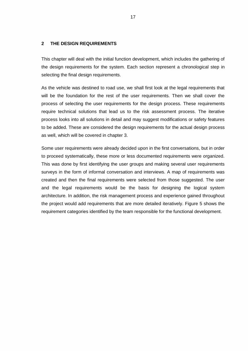
the project would add requirements that are more detailed iteratively. Figure 5 shows the
requirement categories identified by the team responsible for the functional development.
18
Collected requirements
User requirements
Legal requirements
Risk management process
Driver
Operator
Service staff
Researcher
LUT PR
Finnish laws
EU directives
UNECE regulations
Passenger
Selected requirements
Specification
Experience feedback (iteration)
Figure 5. The requirements stem from multiple groups that may each have greatly
different wishes and requirements. The specification for the system will be
created from the “selected requirements”.
2.1 Legal requirements
Legal requirements are a vitally important part of gathering the design requirements as
they pose direct and indirect demands on the hardware and control software. Therefore,
this should be done first. The writer would like to emphasize that this should be the very
first step to overcome any later surprises and major setbacks in the design process, and
thus suggests an early cooperation with transport authorities. The vehicle must be
inspected and re-registered once it has been modified. The legal requirements are there
for a reason and all the vehicle modifications must be approved by the respective
authorities. It helps to maintain good documentation practice throughout the project so
that the inspection authority is able to easily investigate the changes and sign an
approval.
Amongst the many regulations related to the CAMBUS project, the following regulations
were relevant for the software project. The most critical are listed in Table 1. The indicated
Finnish regulation enforces the ECE-R100, which lists a number of detailed requirements
for electric vehicles.

19
Table 1. Regulations relevant for the software design process.
Regulation Description of the regulation
Finnish Ministry of Transport and
Communications: Regulations concerning
the structure and equipment of vehicles
and trailers 19.12.2002/1248 changed with
30.9.2011/1064 (Available in Finnish and
Swedish)
18 a § (30.9.2011/1064) Regulations for
vehicles with electric powertrain.
UNECE R-100 Regulation 100, Uniform provisions
concerning the approval of vehicles with
regard to specific requirements for the
electric powertrain
2.1.1 Electrical safety and electromagnetic compatibility
When talking about electric vehicles, there is obviously a great concern for electrical
safety. In Finland, when there is no plug-in charging implemented, the electric safety of an
EV is mainly regulated by ECE-R100. It sets the guidelines for general electric safety and
isolation, the rechargeable energy storage system (RESS), functional safety, and crash
safety (UNECE 1997). Because of its importance in the project, we will discuss the ECE-
R100 requirements in more detail in the next chapter. Within this project, the Low Voltage
Directive covers only work safety while working on the vehicle.
For such an old vehicle, the authorities do not require any official EMC test document, but
the vehicle must still comply with the regulations that were in force when the car was
registered the first time. For safety reasons in general, it is naturally advisable to make
such measurements to make sure that the electromagnetic interference from the vehicle
power systems do not cause any danger to the passengers or people outside the vehicle.
The final commission is done by a qualified person, who must sign approval that all the
electrical systems of the vehicle comply with the regulations.
20
2.1.2 Requirements per UNECE R100
The UNECE has created a regulation concerning the approval of battery electric vehicles.
This was the most important electric-vehicle-specific regulation for the project vehicle. As
per the first date of registration of the vehicle, the revision 2 addendum 99 was used as
the basis. It sets requirements for specification and testing, and for the alteration of this
older vehicle, the requirements can be divided into two categories: the construction
requirements and functional safety.
The construction requirements concern the RESS and all parts of the high voltage bus.
Naturally, the main concern is the electrical safety: the methods of protection against
direct or indirect contact with live parts, and demands for the isolation resistance. It also
explains the methods for testing against the possibility of hazardous contact and the
measuring of the isolation resistance. (UNECE 1997)
The functional safety includes a list of obligatory features and functions that must be
implemented. For example, it states the requirements for how the driving mode is
activated, the requirements for the instrumentation and warning signals, and the safety
functions against unwanted acceleration. As a reference for the accelerator safety
requirements, the ECE-R100 dated 1997 states in section 5.2.2.4 that “a failure (e.g. in
the powertrain) shall not cause more than 0.1m movement of a standing unbraked
vehicle” (UNECE 1997). This was used as a design reference for accelerator safety and is
covered in more detail in section 5.3.4.
2.1.3 Service brake and steering
It was decided early on that the original service brake, steering systems and components
related to either, would be preserved as much as possible and only the power supplies for
these systems were replaced by electrical equivalents. The functionality of the related
original control units was preserved and exploited by the new control systems, where
possible, in order to enhance driving safety. The changes to the steering and brake
system must be documented, and the functionality of the brake system must be
demonstrated and proved during the registration inspection, and during the vehicle’s
annual inspection.

21
2.2 Risk management
In a project of this magnitude and because the outcome is a product that will be used in
public transport, a risk management process must be defined. Optimally, this process
should be active from early on and it may be integrated into the quality management of an
organization. At the least, the strategy of risk assessment and risk reduction should be
integrated into the design processes. The identification of use cases and risk was first
done following the ISO 12100 standard and the guiding document SFS/ISOTR 14121-2.
In principle, the standard is for machine safety, but was found to be adaptable to this part
of the project. The design process also takes controller and software-relevant standards
into account. The relevant standards are listed in Table 2.
Table 2. The most relevant standards for the software design process.
Standard Description of the standard/part
SFS-EN 12100 Safety Of Machinery. General Principles For Design. Risk
Assessment And Risk Reduction
SFS-ISO/TR 14121-2 Safety Of Machinery – Risk Assessment – Part 2: Practical
Guidance And Examples Of Methods
IEC/TR 61508-0
Functional safety of electrical/electronic/programmable
electronic safety-related systems. Part 0: Functional safety
and IEC 61508
SFS-EN (IEC) 61508-3
Functional safety of electrical/electronic/ programmable
electronic safety-related systems. Part 3: Software
requirements
SFS-EN (IEC) 61508-4
Functional safety of electrical/electronic/ programmable
electronic safety-related systems. Part 4: Definitions and
abbreviations
ISO 12100 states: “the risk assessment is a series of logical steps to enable, in a
systematic way, the analysis and evaluation of the risks associated with machinery” (SFS-
EN ISO 12100 2010). The main term risk assessment is divided into two subjects. The
first comprises of risk analysis, which covers the first three steps described in the section
2.2.1. The fourth one is called risk evaluation. After the risk has been evaluated it is
assessed by the risk reduction process, which is introduced in more detail in section 2.2.2.
22
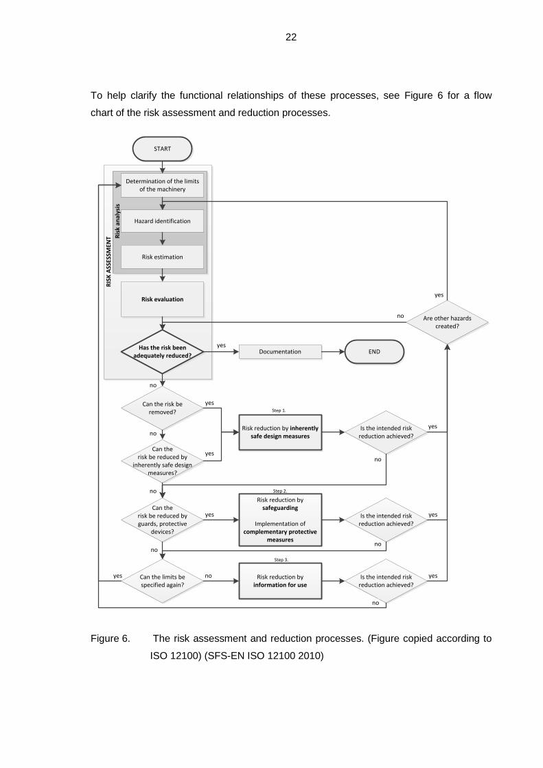
To help clarify the functional relationships of these processes, see Figure 6 for a flow
chart of the risk assessment and reduction processes.
START
Determination of the limits of the machinery
Hazard identification
Risk estimation
Risk evaluation
Has the risk been adequately reduced?
RIS
K A
SSES
SMEN
T Ris
k an
alys
is
Can the risk be removed?
no
Can therisk be reduced by
inherently safe design measures?
Can therisk be reduced by guards, protective
devices?
Can the limits be specified again?
no
noRisk reduction by inherently
safe design measures
yes
yes
Documentationyes
END
Risk reduction by safeguarding
Implementation of complementary protective
measures
yes
Risk reduction by information for use
Is the intended risk reduction achieved?
Is the intended risk reduction achieved?
no
no
noyes
Is the intended risk reduction achieved?
no
no
Are other hazards created?
no
yes
yes
yes
yes
Step 1.
Step 2.
Step 3.
Figure 6. The risk assessment and reduction processes. (Figure copied according to
ISO 12100) (SFS-EN ISO 12100 2010)
23
2.2.1 Risk analysis
According to SFS-EN ISO 12100, the risk analysis begins by determining the limits of the
machinery. This must include the intended use and reasonably foreseeable misuse. In a
vehicle, this would be analogous to any abnormal way of operating, for example excessive
pumping of the accelerator pedal while driving, an excessively long time with full power,
using controls in abnormal way and so forth. The system must always be able to handle
the requests from the driver controls to operate the vehicle in a safe way, and the
subsystems must be able to reduce their operation or go into a fail-safe mode to prevent a
breakdown, and avoid hazards or hazardous situations. (SFS-EN ISO 12100 2010)
The next procedure is identifying the hazards related to the machinery, and the associated
hazardous situations (SFS-EN ISO 12100 2010). There are readily available checklists to
help the assessment process, for example in the standard ISO 12100. These lists help in
obtaining an overall view of the risks and their root causes and how to eliminate or reduce
them.
When the hazards and hazardous events have been identified, the associated risk must
be estimated. In this case, a method called risk graph was used. The risk graph method
assess severity, frequency and probability of an event, and the possibility to avoid it. The
result of this assessment is the risk class, which is given different safety integrity levels.
When all the risks have been estimated, they must then be evaluated to determine the
methods required to reduce the risks to an accepted level. (SFS-EN ISO 12100 2010)
The standard IEC 61508 deals with risk management in conjunction with the electronic
control equipment. However, the reliability estimates mentioned in the IEC 61508 were not
available for the majority of the preselected and original vehicle components. The risk
assessment was thus executed regarding personal estimates of the assessment group.
Because of limited resources, the failure mode and effects analysis (FMEA) was omitted.
2.2.2 Risk reduction
Risk reduction follows risk analysis. The risk reduction process refers to the elimination of
hazards to an acceptable level by using so-called protective measures. The protective
measures may be anything from safety covers to instruction manual. It may be necessary
to repeat this process iteratively in order to reach the predefined level determined as
acceptable risk. This level is usually referred to as ALARP, which is an abbreviation for
“as low as reasonably practicable”. ALARP tools observe several factors, for example,
24
codes and standards, cost benefit versus risk assessment, good practices and
benchmarking. The ALARP assessment was greatly simplified because of the lack of
resources, and the project team determined the accepted level loosely. (SFS-EN ISO
12100 2010)
Protective measures are divided into those implemented by the designer and those
implemented by the users. According to the standard, the designer is responsible of
implementing protective measures, which can be further divided into three sub-measures:
inherently safe design measures, safeguarding and complementary protective measures,
and information for use (SFS-EN ISO 12100 2010). The first consists of all the regular
safety aspects of the design, from choosing the technology to ergonomics. In addition, the
electrical safety is a part of this step. The basic requirements for the electrical safety are
set by the ECE-R100, so the residual risk should be evaluated after fulfilling its
requirements.
The second measure mentions safeguarding and complementary protective measures, for
example the emergency stop switch. In addition, the protection from live contact required
by ECE-R100 is a part of this design category. This would include all sorts of shields,
covers and detecting the state of these safety features by an isolation resistance-
monitoring device, similarly as to what ECE-R100 requires from the fuel cell vehicles
(UNECE 2013). As for the control system, it must include basic diagnostic and protective
features. (UNECE 1997)
The third measure relates to instrumentation. For the user, the levels of risk reduction
include the user organization and its safety culture, training the users (driver, service
personnel) and training the rescue teams that may have to work on the equipment after an
accident.
The results of the ISO 12100 analysis were used during the design process for the logical
and technical system architectures, as well as for the basis of software architecture
planning. As most of the hardware components were preselected, and the scope of this
work was limited to software implementation, the actual technical components and the
physical implementation of the technical system architecture is covered only as seen
necessary to help understand the software development process and requirements
therein. The requirements for the software design were further refined using the principles
of IEC 61508-3. The standard IEC 61508 will be briefly introduced in section 2.4
concerning the functional safety of the equipment.
25
It is rather obvious that some new risks and dangerous situations are detected during the
development processes, at the latest during the actual testing and use, but the majority of
the risks related to the control system and equipment under control can be thought of
before proceeding with the actual construction. As the nature of the risk management
process is iterative, there must be effective means to document the requirements, control
the development process and maintain a revision history for all the documents involved in
the development process. This, of course, helps to plan the SRE and safety architecture
as early as possible. (Schäuffele et al. 2013, 198)
An example of the risk assessment documents is shown in the Appendix I. It includes a
part of the forms used in risk identification, risk assessment, risk reduction and risk
evaluation after the risk reduction process.
2.3 Typical risks
In order to begin identifying risks, a literature search was carried out and revealed two
Finnish reports related to bus fire incidents. The earlier report was published in 2010 by
the Technical Research Centre of Finland (VTT) and concentrates more on overall safety
enhancements (Kallberg 2010). The Finnish Traffic Safety Authority (TRAFI) has
published more detailed statistics and analyzes of bus fire hazards between 2010 and
2012 (Kokki et al. 2013). These reports were examined to better understand the most
common causes for bus accidents and what would be the obvious risks to which to pay
attention. Neither of the reports cover the newer hybrid or fully electric buses. In addition,
the author consulted a technical specialist at an insurance company and the vehicle
systems were examined together to find any suspicious implementations and potential
risks (Makkonen 2015).
The three major risks categories were identified as fire hazard, road accident and electric
shock. According to the report by Kokki et al., the main reasons for fire hazards are
mechanical overheating (brakes, bearings), malfunctions in the electrical systems or
short-circuiting due to failing electrical insulation and oil or fuel leaks on hot engine
components (Kokki et al. 2013). According to the specialist, the fire risk in the engine bay
is amplified especially if the engine bay is not regularly washed and flammable
substances and dust are allowed to accumulate on the engine. The insulation problems
can result from abrasion, as there is a lot of vibration present during the use of the vehicle,
but also chemical and thermal exposure, or aging (Makkonen 2015). The humidity in the
air affects the isolation resistance, as well, and can easily render the situation even worse.
26
Inevitably, the risk of short-circuit is also a risk of electric shock in the case of high voltage
equipment in an electric vehicle. Thus, the importance of proper wiring, shielding and
cable support should be stressed. By the requirements of ECE-R100 and common
practice, the cables connected to the HV system are color coded orange (UNECE 1997).
It is also to be noted that the risks of these dangerous situations may accumulate from
each other.
The ECE-R100 regulation describes the requirements for protection against contact with a
part that has dangerous voltage and the appendices describe means to test the
conformity of the protection (UNECE 1997). However, this is more related to the design of
the technical system architecture.
The regulation also describes test methods that must be used to measure the isolation
resistance of the system (UNECE 1997). The ability of the control system to react to a HV
insulation problem relies on an isolation resistance-monitoring device that constantly
monitors the resistance between the HV system and vehicle chassis. Depending on the
failure mechanism, the inverters may be able to detect a problem with the motor wiring
and consequently cancel their operation internally.
The failure mechanisms related to the possible origin of the above-mentioned dangerous
situations are linked to the software design by means of detecting these situations in order
to prevent greater problems. This may include the fault messages from the functional
modules or dealing with the symptoms of a blown fuse or a broken relay.
2.4 Functional safety of the control equipment
The IEC 61508 standard is a functional safety standard, which has been applied to
various industries. According to the definition in IEC-TR 61508-0 the “functional safety is
part of the overall safety that depends on a system or equipment operating correctly in
response to its inputs” (IEC/TR 61508-0 2011, 10). It covers hardware failures, operator
errors and environmental changes. The title of the standard IEC 61508 refers to the
functional safety of electrical/electronic/programmable electronic safety-related systems in
general. While this standard was used for the automotive applications as well, the recently
created ISO 26262 is specifically for the functional safety of road vehicles. Both of these
standards were observed, but they were discovered too heavy for the project’s needs. The
methods of IEC 61508 were observed together with Schäuffele at al. (2013) to form a
semi-formal method suitable for the minimal resources of this project. Specifically, the

27
guidelines for the software design methods of part three were used during the
specification and verification processes. IEC 61508-3 also gives guidelines on risk
reduction during the software design process. (SFS-EN 61508-3 2011)
One key difference in the philosophy of IEC 61508 and ISO 26262 is how they see the
equipment under control (EUC), the safety related equipment (SRE) and equipment under
test (EUT). In IEC 61508 they are separate while in ISO 26262 they are more integrated.
IEC 61508 was not developed for the needs of automotive engineering and usually in the
control topology, it is sensible to integrate the safety features directly into the control
system itself. (Reif et al. 2014, 254; Schäuffele et al. 2013)
The risk level correlates to safety integrity level (SIL) which determines the methods of
engineering to reduce the risks to a predetermined accepted level. The SIL levels are
numbered from 1 to 4. For example, usually, in a car with a drive-by-wire system the
engine control unit reads the signal from accelerator pedal and controls the engine to fulfill
the driver’s request. Safety is typically approached here by adding diagnostics that utilize
both hardware and software functions. In more advanced systems, everything is doubled
so that the system can analyze and determine if either one of the input signals is plausible
and to continue safe operation. Usually all the hardware from the power supplies of the
position sensor to the A/D converters are separate. While this sounds already quite safe,
the equipment itself may not be perfectly stable and the higher SIL2 (or ASIL2) categories
practically require equipment that monitors the control equipment itself (EUT). These
systems include a separate RAM memory, a processor that runs identical code, and a
system that compares the results between the processors. According to the IEC 61508
part four, its purpose is to detect internal hardware failures and so-called transient soft-
errors occurring “in the memory, digital logic, analog circuits, and on transmission lines,
etc. and are dominant in semiconductor memory, including registers and latches” (SFS-
EN 61508-4 2010). An industrial PLC complying with the IEC 61508 SIL2 requirements
would generally be called “a safety-PLC”. Embedded processors capable of internal
monitoring are also easily available. (Schäuffele et al. 2013)
The system redundancy architecture is commonly referred to by the term MooN or “M out
of N”. It describes the level of redundancy involved with number replacing the letters M
and N (Schäuffele et al. 2013). For example, 1oo1 (1 out of 1) means that there is no
redundancy involved, as only one input is used. Using a 1oo2 architecture instead, the
safety fault tolerance can be increased, as there are two input values that can be voted
upon. However, the availability of the equipment may not be increased if there are no
28
means to continue safe operation while the other input is declared faulty. This can be
addressed by adding diagnostic functions. The diagnostic capability is marked with a
trailing letter D. For example, in a 1oo1D architecture, the quality of the input signal could
be monitored according to a behavior model, and in case the diagnostic system detects a
fault, it can independently deactivate the module output.
The risk assessment was done first to collect the obvious design requirements and later
on as many times as necessary until the risk had been reduced to an accepted level. The
process in its entirety has been described in its own documentation and the forms
produced by the process are archived by the CAMBUS project.
29
3 THE SYSTEM AND SOFTWARE DESIGN
This chapter will examine how the left side of the formerly introduced V-model proceeds
systematically, and has a detailed look into each step. At the end of this chapter, the
software is set up to work together and the fourth chapter shall proceed with tests from the
right side of the V-model.
Writing the specifications may be time consuming in the case of a complex system with
nested functional interactions and demands for fault tolerance and diagnostics. The
legislation is the foundation for the vehicle safety requirements. The user-interface-related
functionality is mainly derived from traditional solutions in commercial vehicles.
The user interface consists of the instrumentation and the controls. The driver is supposed
to receive warnings and fault reports through the instrumentation, and control the system
via the controls and switches on the dashboard. Because of the high risk involved, a
diagnostic system monitoring the controls and functionality of the system is required to
lower the level of risk involved in a drive-by-wire system (Schäuffele et al. 2013, 211-214).
The visual instrumentation will present statuses, instructions and messages through a
dash display and signal lights. All the functions related to driving, monitoring and coping
with fault situations, as well as some functional descriptions, are described in the user
manual. In addition, troubleshooting tips and service instructions are gathered in the
manual. Because some of the maintenance and service operations might impose serious
risks, the manual must give step by step instructions and cover all the related safety
requirements, description of tools and use of protective equipment (SFS-EN ISO 12100
2010).
3.1 Logical system architecture
The specification of the logical system architecture is the end-result of function
development. In this phase, all the functionality and interaction of the modules in the
vehicle must be planned. The logical architecture plan must fulfil the user requirements on
a logical level.
The drive system of a HEV requires a far more complex control system compared to the
system in a plain EV. There are more devices on-board and numerous operating
conditions for both the series and parallel operation, not forgetting their combined
operation. The technical functionality must then be coupled by a geographical drive

30
control system (by a GPS or hard-coded route map), multiple-regeneration-related control
algorithms, as well as crawl, hill hold, anti-jerk and slip control algorithms. To add to the
complexity, there are also unpredictable changes in traffic situations, weather conditions
(e.g. temperature management) and driver habits, which may always produce unexpected
behavior. For example, a rapid change of torque direction will easily cause the slack in the
powertrain to create noise and a jerking motion, or even damage the powertrain
components. Despite the sophisticated system control algorithms, the driver should still
negotiate the traffic in a predictive manner to exploit the potential of the hybrid system.
(Reif et al. 2014, 773)
A meticulous planning of the architectures is vitally important. The nested modules and
systems, their failure mechanisms and the diagnostic functions required to detect the
failures, create an abundance of software conditions and algorithms that must work
together flawlessly in order for the driver to feel that the vehicle is safe and operating
logically at all times. Many of these requirements seem relatively simple when observed
independently, but in reality, combining them all together to form a working union is quite
a demanding task. Even when the torque control system is able to operate all the drive
components properly, the Battery Management System (BMS) conditions for charge and
discharge must be observed and the torque requests of the drive components may be
forced to be limited accordingly. This means that in a well-designed and tuned system the
driver interface (e.g. a simple device like accelerator pedal) masks the complex internal
functionality of the hybrid control system. The driver does not need to concentrate on
handling the equipment in any peculiar way, but can drive the vehicle just as any usual
vehicle and concentrate on the driving and traffic situations.
In addition to the basic features in normal healthy operation, the logical system
architecture should already have a plan for the safety logic: fail-safe, fail-operational, fail-
reduced. Only at this stage, however, it was determined that a means of monitoring and
diagnostics would be required at least for the accelerator pedal, and the internal
functionality and implementation of the diagnostics were designed first on a general level.
The safety logic is discussed more thoroughly in section 3.3.
3.2 Technical system architecture
The typical order of a design process beginning from scratch would assume that now the
technical means to accomplish the requirements set by the logical system architecture are
being selected. This phase is a part of the system development phase. As mentioned in

31
the introduction, some of the equipment was pre-selected and this steered the technical
architecture towards a specific topology, where there are two main control units.
Figure 7 presents a brainstorming diagram that demonstrates how the equipment and its
functionality are interconnected. The designations used are derived from common
automotive terminology.
VECU
Instrumentation
Body integration
Chassis integration
ABS
ASR
ECS
Instrument cluster
Switches
Levers
Pedals
Doors
Hatches/lids/covers
Lights HCU
BMS
MCU
ECU
TCM
TMS
auxiliaries
Drive motor inverters
Generator inverter
Air compressor
Hydraulic pump
Clutch
EDC
Instrument cluster
Water valves
Water pumps
Fans
Aux. heater
Monitoring
Anti-jerk
PC interface
Online programming
Datalogging
Information displays
Ethernetswitch
Ethernetswitch
Multiple LMUs
Additional measurements
Heating
Figure 7. An overall view of the relationships of the specified equipment required to
fulfill the specification of the logical system architecture. Abbreviations in the
figure: ABS Anti-lock Brake System, ASR Anti-Slip Regulation, BMS Battery
Management System, ECS Electronic Controlled Suspension, ECU
Electronic Control Unit, EDC Electronic Diesel Control, MCU Motor Control
Unit, PC for Personal Computer, TCM Traction Control Module, TMS
Temperature Management System.
The communication network topology consists of one main network and several local
networks. On the top level, connecting the PLCs and data loggers, there is an Ethernet
network, where messages are sent via UDP protocol with CRC checking enabled. The
rear end separated CAN networks are hosted by the HCU control unit. The drive inverters
communicate via the 29-bit CANopen standard, the diesel control unit via 11-bit CAN 2.0
according to VW CAN version 3, and the battery management unit communicates with
CAN via SAE J1939 protocol. The inverter bus operates at 250 kbit/s, while the battery
and ECU CAN bus operates at 500 bit/s speed. The VECU unit uses one additional CAN
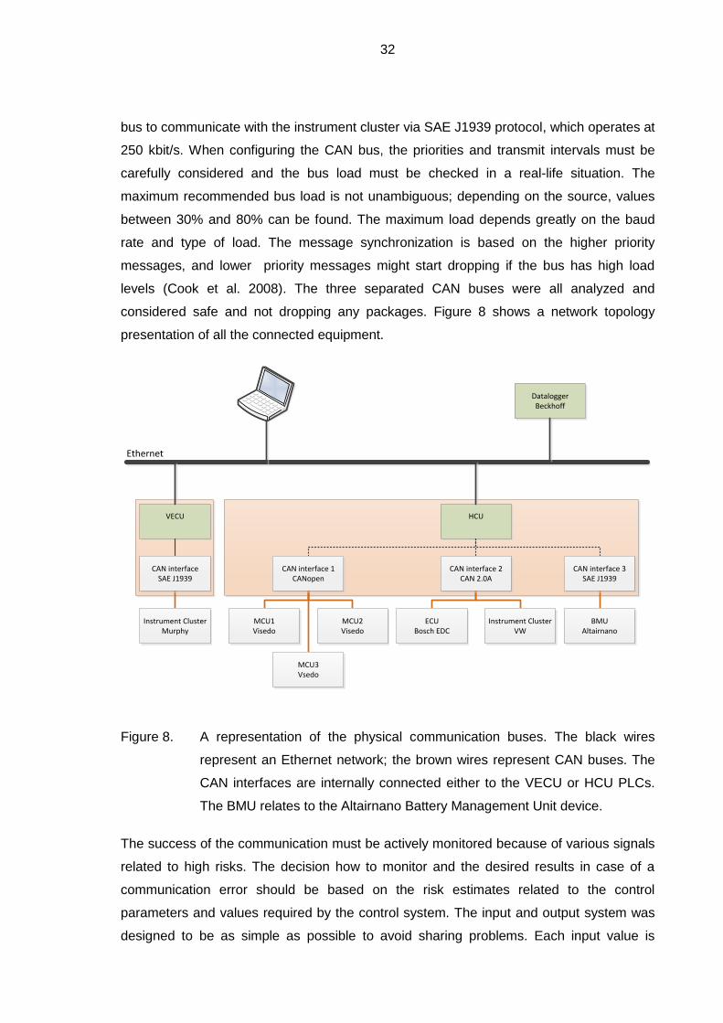
32
bus to communicate with the instrument cluster via SAE J1939 protocol, which operates at
250 kbit/s. When configuring the CAN bus, the priorities and transmit intervals must be
carefully considered and the bus load must be checked in a real-life situation. The
maximum recommended bus load is not unambiguous; depending on the source, values
between 30% and 80% can be found. The maximum load depends greatly on the baud
rate and type of load. The message synchronization is based on the higher priority
messages, and lower priority messages might start dropping if the bus has high load
levels (Cook et al. 2008). The three separated CAN buses were all analyzed and
considered safe and not dropping any packages. Figure 8 shows a network topology
presentation of all the connected equipment.
VECU
CAN interfaceSAE J1939
Instrument ClusterMurphy
HCU
MCU3Vsedo
MCU1Visedo
CAN interface 1CANopen
MCU2Visedo
CAN interface 3SAE J1939
BMUAltairnano
ECUBosch EDC
CAN interface 2CAN 2.0A
Instrument ClusterVW
DataloggerBeckhoff
Ethernet
Figure 8. A representation of the physical communication buses. The black wires
represent an Ethernet network; the brown wires represent CAN buses. The
CAN interfaces are internally connected either to the VECU or HCU PLCs.
The BMU relates to the Altairnano Battery Management Unit device.
The success of the communication must be actively monitored because of various signals
related to high risks. The decision how to monitor and the desired results in case of a
communication error should be based on the risk estimates related to the control
parameters and values required by the control system. The input and output system was
designed to be as simple as possible to avoid sharing problems. Each input value is
33
designated to a module handling the input values and writing them to a global register,
which the other modules may read. The control of the outputs was limited by coding rules
so that the module controlling the output may only get the input value from a specific
higher block.
The next phase included considerable detective work to be able to combine all the old
body electrics and electronics and integrate them with the new system. This was required
to comply with the regulations as well. The EDC functionality and ECU CAN bus
messages were studied from a manual called Bosch EDC 15+ Funktionsrahmen. In order
to be able to read the ECU CAN bus, the original Volkswagen instrument cluster was
required. Without the instrument cluster, or some other control unit sending messages, the
ECU CAN state machine would enter error state and cease to communicate (Bosch
2002). However, this allowed us to make use of the instrument cluster CAN messages, as
it is reading some of the sensors and signals and broadcasting their values and states
over the CAN bus.
3.3 System safety architecture
At this point, the functions, all the possibilities and limitations of the equipment should be
known. The previous assessments must provide information of the requirements for the
design of the system safety architecture. Regarding the level of safety built-in to the
selected equipment, the possibilities of adding safety by software implementation is
observed.
Each of the main functions should have a target level of redundancy. The pre-selected
components allow a 1oo2 safety architecture for the traction motor inverter control,
although as fail-reduced operation in terms of the maximum generated torque available.
The torque request signal safety is secured by monitoring the communication pathways
and safety signal. Each module in the control chain will monitor the signals it is receiving,
but the transmitted data is not doubled. There are no multi-channel implementations that
would, for example, allow voting for the inputs in problem situations.
Another drawback is that at the highest level, the selected control equipment cannot
analyze its own behavior to ensure flawless operation. The control system would benefit
from the use of safety PLC units that run the same program code within independent
processors and memories. They would be able to detect internal control unit failures and,
depending on the configuration, continue operation to allow continued safe operation or a
34
safe stop for instance. Today’s vehicles typically have dual individual power supplies
incorporated for the sensors, they read the sensor values with separate ADCs, the signal
processing is done simultaneously with two separate hardware, and the healthiness of the
system and its main processes are evaluated internally by dual processor technology. The
Visedo inverters have an external stop command signal that is specified as SIL2 class
functionality. Additional safety can be achieved by linking this to the PLC and an
emergency switch operated by the driver.
Schäuffele et al. (2013) explains the safety logic planning, which requires determining a
fail-safe (FS) mode for each unit. For example, from the perspective of the battery
management system, FS is a state where the RESS is uncoupled from the main HV DC
bus and the internal pack contactors are uncoupled. For the internal combustion engine, it
is the state where the ECU is off, and the fuel valve solenoid is de-energized and the
generator control is shutdown. For the accelerator system, the torque request is reset
whenever a serious problem with the input signals is detected. The other common failure
modes are called fail-operational (FO) and fail-reduced (FR). For example, the diagnostic
functions of the accelerator module include features that allow resetting the fault condition
if certain amounts of cycles have been fault free. This kind of behavior is called fail-
operational. If the failure is found repeatedly, the error is marked permanent and the
accelerator will enter the fail-safe mode. Typically, this kind of logic could be described as
FO/FO/FS, which means to allow resetting twice before entering fail-safe mode. Some
equipment can utilize the FR mode, for example, the inverter power output may be limited
due to temperature conditions in either the inverter or the traction motor. (Schäuffele et al.
2013, 113)
The more complicated safety measures also add to the price of the equipment so it is
necessary to determine the requirements and safety category of each unit. For example,
driving an air compressor is not the most critical task in terms of processing power or
software complexity. There is not much to do in case of an equipment failure. The
compressor system consists of an overpressure relief valve in case the inverter decides to
run continuously, and vice versa, in case of the compressor not running, the regulations
demand a pressurised air tank that will allow a certain amount of braking with full brake
power. The driver must get a warning of the low pressure in the system as well. The
requirements must be determined by the sum of all the safety measures in accordance
with ALARP. In the end, it is the driver who makes the final decisions while driving the
vehicle, thus it is crucial to inform the driver of such failures through the instrument cluster
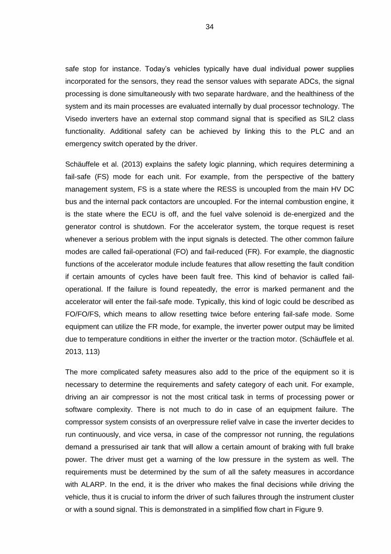
or with a sound signal. This is demonstrated in a simplified flow chart in Figure 9.
35
Control operation (normal state)
Fault detected/active?
no
Remedies?
yes
Able to resume? yes
yes
Enter safe state
no no
Issue warning or fault signal
Enter reduced state and Issue warning
Can continue in reduced state?
yes
no
Figure 9. A flowchart demonstrating the principles of a fault handling process. The
yellow color of the fail-reduced state represents the warning color in
automotive instrument cluster (can still drive) and the red color a major
failure or emergency. The safety logic can differ from unit to unit, depending
on the risks involved, and some will allow resetting of the fail-reduced or fail-
safe state, while some enter fail-safe mode permanently. (Schäuffele et al.
2013, 113)
The software architecture is typically laid out of modules or units. This, observing from the
highest level, follows the logic of equipment under control and control system of IEC
61508. In this case, all these control units are integrated into two main control units and
the topological relations are mainly dictated by the physical location of the relevant
equipment. In a satellite topology, where all functional equipment is controlled by its own
control units, one failing unit will not cause the whole of the system to collapse. In an
integrated system, there is the danger that in the case of internal failure of the control
electronics, the whole system can suddenly behave erratically or cease to function. In any
safety critical system, a dedicated safety controller would be beneficial. A thorough
estimation and comparison of the reliability of the chosen equipment is however out of the
scope of this work.

36
A good design rule is to simplify as much as possible. There should be a clear logic to as
to how the features and functions in the software are controlled, how the data is managed,
and where the global values are set. When the outcome is minimalistic and unambiguous,
it is easier to determine whether or not there is danger of loops or if the state controls
cover all of the possible failure situations. A simple and well-organized structure is also
easier to debug online.
3.4 Safety aspects of the software project management
The software project management refers to methods required in organizing software
projects and concerns the overall software safety. This aspect of safety does not relate to
the actual safety functions implemented with software, but the safety achieved by properly
organizing the software project. (Schäuffele et al. 2013)
Basic safety thinking in the software process itself includes:
documenting (to be done throughout the project),
software architecture planning,
coding rules / management,
software versioning,
testing, and
validation.
Documenting the process is vitally important. Proper documenting and access to the
documents ensures the flow of information within the team or teams. In regard to
software, the output from the previous processes were used as the input for the software
process, thus a carefully planned logical and technical structure are the foundation of the
software development process. The software architecture and planning is explained more
in detail in section 3.5. The section also describes the programming rules that were
created after software architecture plan was agreed upon.
One extremely important factor is software versioning. It is the key to keeping the
programming process in order. When a software function is complete, it is subjected to
testing. If the performed tests approve that the functionality is as specified, that it is safe
(no risk of deadlocks) and that the module fulfills its task, it is marked as verified. The
compiled stable versions, especially the release or boot versions, should only include
verified software modules and vice versa, and the test versions should be marked
37
accordingly and only be used temporarily. This is because any thoughtless changes in the
software can result in unexpected and unknown behavior. (Kasurinen 2013)
Thoughtful planning can reduce the amount of resources this phase consumes. The
process of testing and verification is required for each module that has been changed and
sometimes for modules the changed module may affect. In a well-planned architecture,
the verified software modules will not usually require any fundamental changes. In order
to minimize the risks, the release software version should have only validated modules.
Versioning will keep track of the development versions of the modules, indicating whether
it is a beta, verified or validated version. It is also good practice to maintain a version
history for each module. (Kai 2010, 217) (Schäuffele et al. 2013)
If problems should be detected in use, the relevant versions should be marked with some
kind of identifier and determine a priority class for the fixing required. This ensures that a
stable version may be compiled anytime without the risk of including old and possibly
faulty code.
3.5 Software architecture
It is vital to create a software architecture plan that allows combining all the necessary
logical operations and keeping the internal communication and control programs simple
and straightforward. The IEC 61508-3 annex A expresses recommendations for software
development according to the identified risk classes. It would have required more
resources to create fully compliant software, so it was mainly consulted for guidance while
planning the software. Semi-formal methods were used to document the requirements.
The chosen requirements were modelled as function blocks and their interconnections
were planned. The functions related to torque control were assessed as SIL2, which
largely dictated the technical requirements for the software architecture. According to
Pressman, the design process begins with data, architecture and interface designs, and
then proceeds to procedural design, which is related more closely to the logical system
architecture design (Pressman 2001, 423).
It was decided that the data structures of the modules will keep their own internal
structures, and the requirement for global level variables is minimized to keep the variable
accessing in control. A global registry was chosen for collecting the data from the top level
software modules. A collective data structure was chosen because it could be easily sent
to the other PLC or another device for debugging purposes. The data structure was

38
divided into categories, for example to a sublevel for input and output signals, to further
mimic the situation where the modules may be independent equipment with their own
inputs and outputs. Thus it was important to make a clear decision which levels of
modules or function blocks have the rights to write the information to this global registry.
Logically, the top level module that is calling its submodules, writes the inputs and
observes the outputs of the submodules, while all the relevant information from this top
level module is made accessible for the other top level modules through the global
registry. However, between the layers the input and output system would be preferred
between the layers because of the principle of information hiding. This is a common
programming principle meaning the module interfaces are designed in a way, that only the
data absolutely necessary is given through the outputs (Pressman 2001). According to
Pressman, the greatest benefits are provided in the software editing and testing
procedures. Some regularly required internal values, for example the state of charge read
over BMS CAN, could be written as submodule outputs, but the practice was omitted.
Instead, the submodule is writing all the information received over CAN bus to a specific
global data structure. Similarly, it is also typical in automotive control units that the unit
sends a great variety of data over CAN and the data is available to all other control units
in the network.
The foundation of the software architecture was laid out as individual modules that in real
life would most likely be implemented as independent controllers. Each is implemented as
their own independent program. The module interactions, and their interfaces, are
designed in a similar fashion. Some of the modules can operate on a run-signal without
any other input signals and on a higher level, the status may be followed either by
checking the state of the module or its status outputs. The hierarchy is carefully planned
with as much exclusivity as possible, preventing random write access to variables and
parallel or conflicting control commands. It was also noted that this way the program could
be run sequentially and the use of software semaphores could be avoided. A simplified
module hierarchy of the VECU and HCU can be seen in the Figure 10.
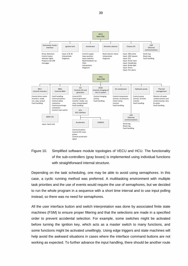
39
VECUMain FSM
Accelerator
Direction selector
Instrument cluster interface
Chassis I/O
Ignition lock
Driver detectionControl status indicator lightsPrepare end CAN messages
Input 15 & 30InterpretateDiagnosis
Control supplyInput positionInput switchesRead kickdown sw.FilterInterpretateDiagnosis
Read selector statusInterpretateDiagnosis
Input: ABS activeInput: ASR requestInput: ECSInput: Driver doorInput: HandbrakeInput: Brake lightInput: DoorsInput: Fire alarm
UDPEthernet
communications
Send msgRead msgFault handling
Input: Hatch (x5)
HCU Main FSM
DCDCControls charging of
the LV system
Air compressor
ICEControls ICE and
generator
BMUControls BMU
MCUControls inverters
Hydraulic pump
Thermal management
Control drive motor inverters: mode, run, stop, torqueFault handling
Fault handlingCommunicationsControl safety contactorsControl precharge contactorsControl main switch
Control charging activityFault handling
Control compressor activity: oil pressure, motor temp, inverterFault handling
Control pump activity: oil level, inverterFault handling
Monitor all water cooled systems and control pumps, fans & valvesFault handling
ECUEDC interface
CommunicationsControl EDC main powerControl accelerator signal
UDPEthernet
communications
Send msgRead msgFault handling
Accelerator
CANBUS
Control ECUControl generator inverter: mode, run, stop, torque/speedFault handling
BODY I/O
Figure 10. Simplified software module topologies of VECU and HCU. The functionality
of the sub-controllers (gray boxes) is implemented using individual functions
with straightforward internal structure.
Depending on the task scheduling, one may be able to avoid using semaphores. In this
case, a cyclic running method was preferred. A multitasking environment with multiple
task priorities and the use of events would require the use of semaphores, but we decided
to run the whole program in a sequence with a short time interval and to use input polling
instead, so there was no need for semaphores.
All the user interface button and switch interpretation was done by associated finite state
machines (FSM) to ensure proper filtering and that the selections are made in a specified
order to prevent accidental selection. For example, some switches might be activated
before turning the ignition key, which acts as a master switch to many functions, and
some functions might be activated unwillingly. Using edge triggers and state machines will
help avoid the awkward situations in cases where the interface command buttons are not
working as expected. To further advance the input handling, there should be another route
40
for the signal through a diagnostic system that evaluates the plausibility of each signal.
This is discussed in a bit more detail in section 3.6.
When beginning to translate the design models into operational software, one must
carefully think through the procedures and requirements for loops and all dynamic
behavior in the software. The embedded software safety requires that the software is
implemented in a way that there are no possibilities for a deadlock. There should be no
dependencies that make the software wait for something; instead, each required input or
process state is evaluated against a timeout clock and a failing process is then dealt with
using the rules derived from the logical system architecture. Furthermore, it is also an IEC
61508 recommendation to avoid dynamic structures (objects) in a safety critical system
(SFS-EN 61508-3 2011). The creation of dynamic objects and allocating memory during
the operation could lead to memory leaks or resource pre-emption, which in turn could
lead to unexpected results. Some dynamic behavior may also affect the processing times
and cause timing problems for the more critical processes. When the software is designed
as straightforward as possible and all the code can be run at each cycle with adequate
remaining processor time, it is ensured that there will be no resource conflicts or
deadlocks. (Pressman 2001)
The software algorithms must be well documented so that adequate testing, and later
development, is possible. In this case, the algorithms were first tested in the
MATLAB/Simulink environment with relevant simulations before being testing in the real
environment.
3.6 Monitoring functions and diagnostics
The monitoring and diagnostic functions are the basis for both safety and reliability of the
control system. Their purpose is to ensure the safe control of the equipment at all times,
even after a failure. Obviously, it is important to provide first a safe technical solution, as
already mentioned in section 3.2. Some solutions cannot be made safe or reliable enough
by means of mechanical design and in some cases, a higher level of safety or reliability
through mechanical design would not be cost-efficient. (Schäuffele et al. 2013)
The overall risk may be decreased by embedding software safety functions. In contrast, a
poor software design or careless implementation is a risk in itself. To reduce the risks,
software planning must utilize a sensible, predefined scheme that all the participants
agree to follow. Software safety must also consider the hardware and the possible
41
problems therein, especially in the safety-critical systems with diagnostic capable
hardware. (Schäuffele et al. 2013, 212)
It was decided that all the software modules would have their own means of detecting
safety issues, most of which rely on the equipment manufacturers’ own management and
control systems. Thus, the main requirement is to monitor the equipment status and
handle the fault situations. In a vehicle, it is usually sensible to try recovering the
functionality before entering a fail-reduced or fail-safe state. Thus, less serious equipment
failures would at least allow the driver to maneuver the vehicle into a safe spot.
All the software related to external communications is equipped with several methods of
safety. The communication layer itself is covered by the hardware and relevant software
libraries provided by ABB. For instance, all used communication paths use CRC32 or
CRC16 checksum to verify the received packages, they monitor the transmission intervals
to detect a communication timeout, and include additional functionality that will require the
critical commands to reset to a safe state before allowing the system to resume. In this
system, for example, the module level operation is relatively simple except for the diesel
generator combination. However, considering the multiple failure possibilities, the software
must be able to carry all the necessary information to the highest level of the system so
that it can either reduce or stop operation of a particular module, or command a reset if
permitted. Establishing a comprehensive fault-handling logic requires meticulous
assessment of the possible fault situations and their combinations. Naturally, the most
important software prerequisite is that there are adequate means, for example input
signals, for detecting faults. The detection routines and fault-handling logic must be
tested in real-world situations and the control software must bring the system to the
predefined safe state if necessary.
An additional isolation-measuring device was also specified. When it detects a significant
reduction in the isolation resistance (e.g. in case of short-circuit of one individual AC
phase), the driver is warned and the vehicle is allowed to continue driving in a reduced
mode until shutdown. A new start is not permitted if an isolation fault is still detected.
42
4 THE TESTING PROCESS
This chapter will expand on the testing methods and process used. The foundation for the
software testing process was simplified from the ISO/IEC 29119 and IEC 61508-3
suggested practices. As this project had only minimal human resources, there was no
possibility to create a separate testing organization. To avoid the ethical problems and
minimize the psychological aspects of a programmer testing his own code, an
independent testing organization should always be set up. With the minimal resources
available the test organization is in many cases the person that has created the code,
which is a highly susceptible method because of a higher possibility of blindness for the
mistakes. A separate test organization would be more objective, but the organization also
needs guidelines for the testing. (Kasurinen 2013)
Because of limited resources, the project’s management decided that automated testing
would not be implemented. The software testing was thus done separately for the code,
which was already run in trials and performing in real-life situations. A formal report was
written for each test and its results. Due to the limited scope of this work, only a selected
base version was tested. The critical problems were corrected and the relevant modules
were re-tested accordingly. Other corrections and relevant testing would be done later on
according to the produced test reports. After corrections or additions, the software must
undergo all the testing procedures. Sometimes a small fix is required during use, but in
principle all the changes should start from the design process and thus be documented at
each level, and then tested and validated in the end.
The software architecture map describing the modules and their dependencies are listed.
Each module must have a written description of its functionality. A structural inspection of
the code is performed. The first check will ensure that the commenting is uniform and the
module version numbering is up-to-date. If the functionality of the module is not obvious
from the written description, the modules must have a flow chart describing the process in
more detail. The software written in graphical continuous function chart (CFC) language is
easy to understand and debug. Some examples can be seen in section 5.3.3. In this
project, most of the code is written in structured text (ST) or CFC. The program code,
clearly stating its version, has to be included with the module information package. Then
the inputs and outputs are listed and all cases of their expected behavior are listed. From
here the test cases can be formulated. Each signal should have random noise applied to
create unexpected behavior as well.

43
4.1 Software test principles
The software tests must relate to the specified design requirements. In more formal
development, the test case can thus be planned early in the process. According to
Pressman, the Pareto principle is applicable, which means that it is common to find most
of the errors in a certain small part of the software. The testing process begins from
modules to the higher level software which manages the individual modules. To prevent
the ethical problems and to be more effective, testing should be performed by another
organization, possibly a third party organization.
The first principle of testing is to check the operability of the modules. The modules must
work flawlessly without bugs that would preventing running the code. The second principle
deals with the observability. The code must be easy to debug, the source code must
naturally be available, and all the states and internal variable processing, and the input
and output processing must be easy to interpret and observe. The third principle is
controllability, which addresses combinations of inputs and outputs, their
interdependencies and functional predictability. The fourth principle deals with the
decomposability, which looks at the modular design of the software. This leads to the
principle of the simplicity of the code: the simpler the software is, the easier it is to test and
obviously the less it is prone to bugs. The next principle is testability, which looks at the
structural simplicity. The last principles deal with the stability of the software, its error
handling capabilities and stable operation, and the tester’s ability to understand the
documentation and information. (Pressman 2001, 439)
4.2 Software test methods
The software module tests were done using white and black box methods in a simulation
environment. During the integration tests the handling of erratic real-life signals will be
verified. This is done by either interfering with the physical signals or the software by
adding an interference created by the pseudorandom binary sequence method, or both.
After this phase, the testing of the highest level control system must be performed.
The functional testing of the modules, and their relevant control structures and sequence
controls, mainly consists of checking the normal expected operation and the induction of
abnormal input values, and verifying the fault handling. The abnormal input values must
correspond to the expected failure cases in those modules that include fault handling. A
test plan is made to cover all the preconditions, expected results and postconditions.

44
Sequential operation is tested likewise with attention paid to the expected events at the
inputs and the cases of unexpected operation representing malfunctioning inputs. The
functional test plan is written down in checklist form to ease the testing process and must
include the following scenarios.
The code is to be observed for obvious bugs, for example variable type mismatches and
loops. For this purpose, values out of range are induced (e.g. of wrong types of variables),
to see how the component can handle the situation. The next step would be the boundary
value analysis. In this check, the input values are given from both sides of the borders of
the permitted range. This will address the software configured limits and scaling, and the
internal data structures (e.g. arrays), which have to be checked at their boundaries. In this
case, the software does not have any dynamic arrays or loops, so this is relevant only
regarding the inputs and outputs, and the relevant internal calculations. (Pressman 2001)
The logical functionality must be tested with all the expected combinations. To test the
logical functionality in unexpected fault situations, the tester intervenes in the operation of
the system by forcing the internal values and signals in the programming environment.
This ensures that the coordination of the integrated equipment is tested. This is done by
verifying the expected behavior of the components with all the input and output
combinations. This also correlates to the possible signal diagnostics implemented in the
module, and correct functionality of the diagnostics can be verified. It requires proper
planning of the test cases to test the diagnostic functions in a simulation environment
using noise generators or other means to interfere with the signals. The input value testing
correlates to the missing input signals (e.g. open circuit or short to 0VDC). Some of the
digital inputs might have an algorithm to discover erratic signal behavior, and some of the
analog inputs have model-based behavior or other methods to monitor signal quality. The
diagnostic functions may also react to constant high signals (e.g. short to >10VDC), or
static signals within the permissible range.
Although it was not done here, each module could be monitored for the processor cycles it
needs to finish in different operating conditions. This could be documented with the other
test results and may help to determine if some parts of the software require excessive
processor time, possibly causing problems after the system integration. The overall
process timing was checked with Codesys task monitoring.
45
4.3 Module testing
This phase of testing correlates to the technical system architecture plan. Its aim is to
verify that the technical implementation of each unit or module works according to the plan
(Schäuffele et al. 2013). All the measured values are checked and the operation is
thoroughly verified. Fault handling and entering the fail-safe state must be tested in all of
the internal states of the module. Depending on the type of the error, the module must
either recover or enter the fail-safe state permanently.
A thorough testing of some of the modules would require simultaneous operation of other
modules. For example, it was not possible to test the diesel engine with a controlled load
before the whole powertrain was installed in the vehicle, so only the basic functionality of
each module was tested individually and the mutual operation controlled by the higher-
level software would be tested during the integration tests.
4.4 Integration tests
The aim of this phase is to integrate and verify the cooperation between all the completed
and tested modules. During the process, all the electrical connections and schematics are
checked and revised, if necessary. It is quite common that some minor changes are made
and they are not instantly documented. In this case, everything was checked through and
the input and output systems were tested.
The checking of the overall timing correlates to the hardware load of the CPU. The
hardware processing capacity is tested by applying full load with all the possible features
active. The Codesys cycle time monitor was used to determine whether the hardware load
stays at a safe level, meaning that the processes have an adequate time window to
complete and the processes do not overlap and cause priority and other timing problems.
A list of activities and tests that would cover all the normal operation, and a description of
sequences required for the testing was compiled. Another checklist was made to deal with
the most likely failures, which would be tried in order to see whether the higher-level
control is able to cope with the failure situations of subordinate modules.
As the modules may or may not be able to reset and deal with the errors, the higher-level
controller must be able to wait for it to recover or enter the final fail-safe state. The higher-
level controller must also be prepared in a way that its operation is not fully dependent on
the internal states of the modules; it mainly manages them. This was tested by causing
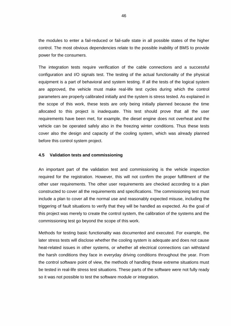
46
the modules to enter a fail-reduced or fail-safe state in all possible states of the higher
control. The most obvious dependencies relate to the possible inability of BMS to provide
power for the consumers.
The integration tests require verification of the cable connections and a successful
configuration and I/O signals test. The testing of the actual functionality of the physical
equipment is a part of behavioral and system testing. If all the tests of the logical system
are approved, the vehicle must make real-life test cycles during which the control
parameters are properly calibrated initially and the system is stress tested. As explained in
the scope of this work, these tests are only being initially planned because the time
allocated to this project is inadequate. This test should prove that all the user
requirements have been met, for example, the diesel engine does not overheat and the
vehicle can be operated safely also in the freezing winter conditions. Thus these tests
cover also the design and capacity of the cooling system, which was already planned
before this control system project.
4.5 Validation tests and commissioning
An important part of the validation test and commissioning is the vehicle inspection
required for the registration. However, this will not confirm the proper fulfillment of the
other user requirements. The other user requirements are checked according to a plan
constructed to cover all the requirements and specifications. The commissioning test must
include a plan to cover all the normal use and reasonably expected misuse, including the
triggering of fault situations to verify that they will be handled as expected. As the goal of
this project was merely to create the control system, the calibration of the systems and the
commissioning test go beyond the scope of this work.
Methods for testing basic functionality was documented and executed. For example, the
later stress tests will disclose whether the cooling system is adequate and does not cause
heat-related issues in other systems, or whether all electrical connections can withstand
the harsh conditions they face in everyday driving conditions throughout the year. From
the control software point of view, the methods of handling these extreme situations must
be tested in real-life stress test situations. These parts of the software were not fully ready
so it was not possible to test the software module or integration.

47
5 RESULTS
The software environment with the basic functional requirements was completed at the
end of the project and the vehicle was subject to official inspection and registration. Many
features of the logical system plan were omitted, but the vehicle fulfilled the legal
requirements, and from this point road testing would be allowed. Measurements related to
energy consumption should be carried out to optimize the system and provide research
data to validate the simulation model parameters. New software features are also
required. The planning required to properly implement these features should be organized
in a manner that the modularity is preserved, and unnecessary, laborious iteration rounds
are avoided. The software architecture was successfully planned in a modular way and it
proved to be easy to add mode internal modules according to the rules agreed upon.
The documentation processes produced a number of manuals and other documents.
These include the original plans, flow and brainstorming charts, user manual with service
and troubleshooting tips. There is also documentation about the risk assessment strategy
and the assessment tables, as well as the test strategy and test results. While the risk
reduction process produced specifications and design features, some were executed as
instructions for use.
The ALARP in the risk processes was determined loosely to lower the probability of risk to
negligible or rare, and the possibility of avoiding the event was determined as likely or
possible. The reassessment verified that the system design requirements could match the
level required by the ALARP process. This concludes that even the SIL2 classified
functions have been addressed seriously during the development and it is highly unlikely
that they would be the cause of an accident. There is at least the possibility that the driver
is always able to intervene and prevent the accident by taking corrective actions.
5.1 Results of the software process
The logical architecture and software functionality were sketched as flow charts and state
diagrams for all the relevant functions. This helped to understand the possible problems in
module interaction. Also the actual programming benefits from a well-made plan. When
the code is divided into tangible blocks, or modules, and the programmers obey the plan,
the risk for dramatic programming errors is reduced. A well-documented plan is crucial
also in the testing phase. Some examples of these charts and diagrams were already

48
used in the text to help understand the described process. An overview of the actual
software module names and their call tree relationships can be seen in Appendix II.
Because the focus of the project was somewhat scattered in the beginning, some of the
plans were actually made later in the project. This mostly happened because of the
pressure to integrate the system before fully understanding all the equipment and that the
vehicle was supposed be in driving condition before any of the module tests were fully
executed and completed. The earliest prototype code used ladder structures, but later on
they were mostly converted to ST or CFC code. Because of the complex functionality
required in the system, and the limitations of the ladder implementation, this change made
the further developing more manageable.
Each software component has the basic information commented in the header. All the
documented test results combine this with the design charts, and list the test cases and
their results. The result form also must include the version identifier as well as the date
and time of the test. Some space for free commenting of the component functionality was
also reserved on the test result form. This was used to write down ideas for further
development or other suggestions.
As mentioned already in the software testing, the CPU load and process timing were
checked with the CPU cycle time monitoring of Codesys. The processing capabilities were
adequate and the hardware load acceptable. The HCU unit has a more powerful CPU,
and even after adding a rather complex anti-slip algorithm there were no cycle time
issues.
Even though the software process did not always proceed as planned, the software was
surprisingly bug-free. Most of the problems noticed were some minor mistakes caused by
negligence, creating critical issues mainly when related to variable type mismatches.
Other problems were usually related to poor initial planning, resulting sometimes in a
completely rewritten module code. The reason why there was a relatively small amount of
errors was probably because the code was actively tested in real-life situations, where the
bugs would be noticed and fixed instantly. Because the vehicle was tested in a closed
environment, this practice was not seen too risky. One conclusion of the testing process
was a suggestion to develop variable naming conventions to include the type of the
variable. This would help both the programmers and the testers. An example of a test
report can be found from Appendix III.

49
5.2 Validation and real-life tests
The validation test procedures were designed to compare the resulting software with the
logical system architecture, in order to verify functionality versus specifications.
Additionally, the commissioning tests should include prolonged stress testing with full load
in the worst-case scenarios, for example, driving in extreme weather conditions and harsh
road conditions, and testing the isolation monitoring in rapidly changing ambient
conditions. This, however, was not possible to arrange during this project. The author
would still suggest committing the bus to such tests to see any design flaws that may not
have been thought of. This would also benefit future projects.
If all the pre-defined safety, legal and user requirements have been met successfully, and
the vehicle has passed the test processes, the project is considered completed and the
resulting product is validated against the design requirements. Because of the nature of
this research vehicle, new user requirements will arise during the use, and thus to keep
the vehicle safe for public use, the iterative development processes must always follow
the systematic approach laid out by this project.
Most of the equipment was pre-chosen and to verify the adequacy of their specifications in
prolonged stress tests is yet to be seen. This mostly concerns the calibration and use
limits set in the software.
5.3 Case example: The accelerator
This section explains the practical implementation of the accelerator system. The
accelerator was chosen because it represents one of the most critical user interface and
control elements. The electric brake, or regeneration control lever, uses essentially the
same program as the accelerator, so the described diagnostic procedures and operational
logic work in a similar fashion. The analysis of the design requirements is described first,
after which the functional requirements and safety aspects are observed. The later part of
this section will present the software implementation itself and the diagnostic features
implemented therein. The overall results of the software processes will be presented in
section 5.1, therefore the results for the accelerator testing is not be presented here in
detail.
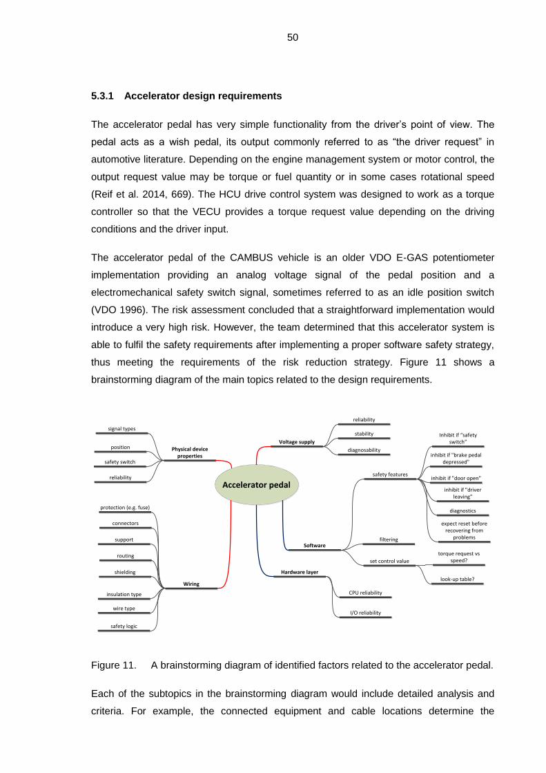
50
5.3.1 Accelerator design requirements
The accelerator pedal has very simple functionality from the driver’s point of view. The
pedal acts as a wish pedal, its output commonly referred to as “the driver request” in
automotive literature. Depending on the engine management system or motor control, the
output request value may be torque or fuel quantity or in some cases rotational speed
(Reif et al. 2014, 669). The HCU drive control system was designed to work as a torque
controller so that the VECU provides a torque request value depending on the driving
conditions and the driver input.
The accelerator pedal of the CAMBUS vehicle is an older VDO E-GAS potentiometer
implementation providing an analog voltage signal of the pedal position and a
electromechanical safety switch signal, sometimes referred to as an idle position switch
(VDO 1996). The risk assessment concluded that a straightforward implementation would
introduce a very high risk. However, the team determined that this accelerator system is
able to fulfil the safety requirements after implementing a proper software safety strategy,
thus meeting the requirements of the risk reduction strategy. Figure 11 shows a
brainstorming diagram of the main topics related to the design requirements.
Accelerator pedal
Voltage supply
Wiring
wire type
insulation type
shielding
routing
support
connectors
stability
diagnosabilityPhysical deviceproperties
position
safety switch
reliability
Softwarefiltering
set control value
safety features
protection (e.g. fuse)
reliability
look-up table?
torque request vs speed?
inhibit if "brake pedal depressed"
inhibit if "door open"
inhibit if "driver leaving"
expect reset before recovering from
problems
diagnostics
signal typesInhibit if “safety
switch”
safety logic
Hardware layer
CPU reliability
I/O reliability
Figure 11. A brainstorming diagram of identified factors related to the accelerator pedal.
Each of the subtopics in the brainstorming diagram would include detailed analysis and
criteria. For example, the connected equipment and cable locations determine the

51
requirements for heat and chemical resistance and the electrical specifications for the
individual cables. This work would mainly consider the topics relevant in the software
design and implementation.
5.3.2 Functional safety requirements for the accelerator
The chosen technical architecture provides the PLC I/O and hardware processing, as well
as some diagnostic features, but the main diagnostic functionality provides several tests
within the software.
The VDO accelerator pedal has a static resistance in series with a potentiometer, which
together produce a known voltage range for a healthy output signal. Thus, the VECU
software proceeds first with a signal range check. The second check considers the correct
operation of the safety switch, comparing its state against the fault-free position signal to
determine whether the switch signal is plausible. The potentiometer signal has slight
variations constantly, so one check is monitoring for a static signal. The quality of the
analog signal is verified with a dual linearization and slope comparison, which detects
excessive noise and severe signal jumps. A check for the potentiometer supply voltage
was also designed.
The faults are prioritized according to the risks involved. Some of the detected failures are
first flagged temporary and the system is allowed to reset them a number of times (fail-
operational). The resetting of an intermittent failure was implemented by counting the
amount of fault-free cycles. If the failure is detected repeatedly or is otherwise persistent,
the fault flag is marked permanent and the accelerator functionality is either reduced or
disabled. After an accelerator related fault is cleared, the pedal is expected to be fully
released before accepting new input values, as described before.
There are multiple communication pathways, which are expected to work flawlessly.
Communication is checked constantly and critical input values are reset to zero if a
communication error or timeout is detected. If the problem is cleared, the receiving unit
will require the physical pedal input to reset as described before. The data flow and the
accelerator functionality are demonstrated in a simplified manner in Figure 12.

52
Inverter application
HCU
VECU
Input ok?Pedal input
Evaluate request
yes
Read input buffers Comm. Ok?
Relay final request
(UDP)
Read input buffers
(CAN)
Comm. ok?
yes
Reset internal torque request
no
Reset torque request
no
Reset torque request
no
Overriding commands?
no
yes
Control torque
Transmit request
Calculate actual request
yes
Figure 12. Simplified command path of the accelerator, including two communication
links. The red dotted lines represent communication over an external link.
Each related step is evaluating the request coming from the higher level,
whether it is reliable or not, and resetting the request in case a problem is
detected.
The accelerator request is evaluated only if the pedal’s internal safety switch is enabled by
depressing the pedal. Thus an accelerator failure of this kind would require two
simultaneous failures of the pedal system. The communication path errors would cause
immediate resetting of the accelerator request (within 20ms) and resuming requires a
zero-position resetting of a faultless system. The final stage of the safety chain is the
inverter software, which in an emergency can only be controlled by the stop signal
mentioned before. However, an inverter user application was designed to require similar
resetting of the input request to maximise the safety and to prevent powertrain jolts.
5.3.3 Software implementation of the accelerator
The main accelerator software unit consists of an I/O handler, a logic that determines if a
torque request is permitted, and a unit that determines how much torque should be
requested. The I/O units first read the pedal related inputs and filter the signals. It also

53
includes a separate path for the signals to pass a series of diagnostic tests. The block will
then generate filtered output signals and the current fault status. The following figures will
demonstrate the accelerator functionality written in the graphical continuous flow chart or
CFC language of the IEC 61131-3. The first accelerator program block can be seen in
Figure 13.
Figure 13. A simplified presentation of the accelerator input handler. The diagnostic run
command is given after a delay, after the voltage from the ignition lock
switch is detected to ensure that the system is in normal state (i.e. there are
adequate supply and input signals available).
Parallel to this, there is a block that controls all the safety related conditions of the
accelerator. The accelerator idle or safety switch, and the brake pedal switch, are treated
as the most important driving related interface safety features. The communication
pathway error handling is also considered one of the highest level safety features.
Whenever a safety feature is activated, it will set a flag. Any of these conditions will reset
the accelerator request in the next step. When all the safety conditions are reset, and the
release of the accelerator pedal is detected, the flag is reset. To prevent a possible
unwanted immobilisation of the vehicle in a failure of one or more of the second level
safety features, there is an override button that can be used to re-enable the accelerator.
This was done to allow the driver to forcedly move the vehicle from a possibly dangerous
location where it has stalled otherwise. Figure 14 shows how the safety flag is being set
and reset.
Figure 14. A simplified presentation of the accelerator reset functionality.
Figure 15 shows the actual conditions which set the enable flag for the accelerator. One of
the control signals is the reset variable of the previous example.
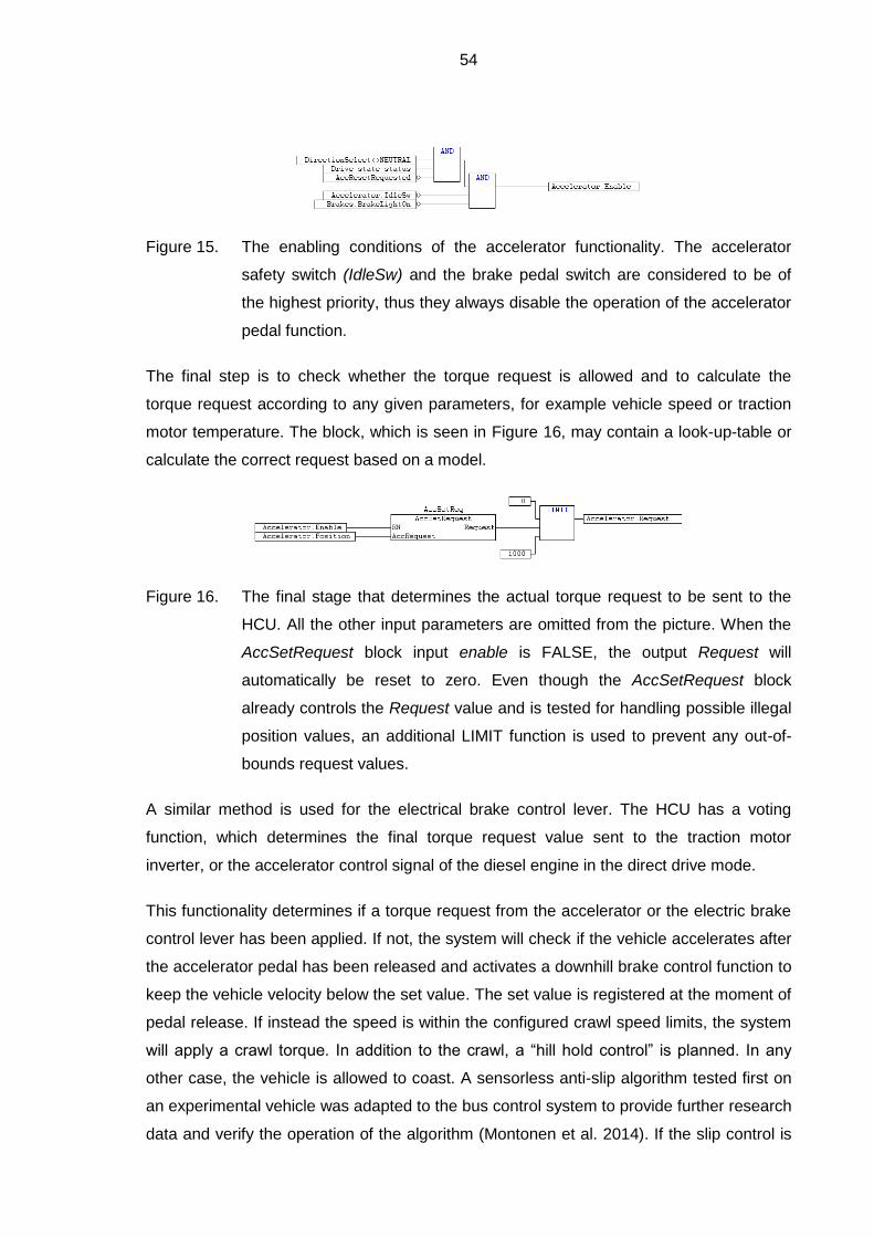
54
Figure 15. The enabling conditions of the accelerator functionality. The accelerator
safety switch (IdleSw) and the brake pedal switch are considered to be of
the highest priority, thus they always disable the operation of the accelerator
pedal function.
The final step is to check whether the torque request is allowed and to calculate the
torque request according to any given parameters, for example vehicle speed or traction
motor temperature. The block, which is seen in Figure 16, may contain a look-up-table or
calculate the correct request based on a model.
Figure 16. The final stage that determines the actual torque request to be sent to the
HCU. All the other input parameters are omitted from the picture. When the
AccSetRequest block input enable is FALSE, the output Request will
automatically be reset to zero. Even though the AccSetRequest block
already controls the Request value and is tested for handling possible illegal
position values, an additional LIMIT function is used to prevent any out-of-
bounds request values.
A similar method is used for the electrical brake control lever. The HCU has a voting
function, which determines the final torque request value sent to the traction motor
inverter, or the accelerator control signal of the diesel engine in the direct drive mode.
This functionality determines if a torque request from the accelerator or the electric brake
control lever has been applied. If not, the system will check if the vehicle accelerates after
the accelerator pedal has been released and activates a downhill brake control function to
keep the vehicle velocity below the set value. The set value is registered at the moment of
pedal release. If instead the speed is within the configured crawl speed limits, the system
will apply a crawl torque. In addition to the crawl, a “hill hold control” is planned. In any
other case, the vehicle is allowed to coast. A sensorless anti-slip algorithm tested first on
an experimental vehicle was adapted to the bus control system to provide further research
data and verify the operation of the algorithm (Montonen et al. 2014). If the slip control is

55
configured as active, the accelerator torque request must pass through the slip control
module. Before the final stage, the torque request must also pass through the anti-jerk
function. A presentation of the command path can be seen in Figure 17.
Accelerator request applied?
Within crawl speed limits?
Register/check speed
Hill hold conditionsFulfilled?
Calculate hill hold torque request
Calculate crawl torque request
Acceleration while acc. pedal
released?
Calculate torque request for
regenerationyes
no
no
yes
yes
Slip control
BrakingAllowed(BMU)?
Pass torque request <0
Acceleratorallowed?
yes Pass torque request >0
yes
Brake request applied?
no
yes
no
Request torque =0
no
no
yes
Anti-jerk control
no
Final torque request
Brake light conditions fulfilled?
Control brake lights
Read input values
Figure 17. A flowchart demonstrating the principle operation of the final torque control
system.
If electrical braking is requested, the torque control function will also request VECU to
operate the brake light accordingly. Combining the electrical braking fluently with the
operation of service brakes is complicated and in this case, it would require upgrading the
old service brake system (Reif et al. 2014, 736). It would be too complicated to pursue
within this project.
5.3.4 Accelerator fault diagnosis
The diagnostics must be able to reliably detect a failing accelerator pedal. The current
setup utilizes the vehicle’s original VDO pedal, which consists of only one film
potentiometer, so the methods of the following paragraphs were designed in order to
ensure the safe operation of the pedal.
The voltage for the potentiometer is supplied and regulated by a PLC analog output. The
analog voltage signal is read by a PLC input module equipped with a 16-bit ADC providing

56
a value with a resolution of 0.4 mV. The program accesses the value every 10ms. To
avoid glitches in the signal, the input signal for the driver request controller is passed
through a median filter with a window size of five. Though the median filter will add delay
to the actual driver request, it was considered not to adversely affect pedal response. The
rates of change of the raw and filtered input signal values are checked. The quality of the
input signal was done by comparing a linearized slope with sample-per-sample slope. The
method was simple and proved to work effectively enough. With current parameters the
system was constantly able to detect noise comparable to 80mV peak-to-peak white noise
generated using a pseudorandom binary sequence (PRBS) algorithm.
The diagnostic rules check the unfiltered signal in 10ms intervals for:
- signal “too fast change” test (2-5 cycles, depending on the test type),
- signal static: 30 cycles (empirically set time limit),
- signal range check: too high, too low (from current value) 3 cycle,
- idle switch error: 3 cycles (empirically set time limit), and
- supply voltage error: 3 cycle.
Some of the example values have a three-cycle minimum because the problem has to be
confirmed to avoid triggering by mistake. A correct value should be tested in real-life
conditions. For example, with one failure the filtered request value could change from 0%
to 100% in an instant, but because of the diagnostic functions, the value is not accepted
and an error flag indicates a too rapid change of signal. Because of the mechanical safety
switch involved, it would take two simultaneous failures and the proper behavior of the
position signal to defeat the diagnostic functions, which is why it is highly unlikely that the
accelerator pedal could cause an uncontrolled acceleration.
To assess the delays in the communication path with the information given by the
equipment manufacturer, the communications block will provide a new value in average
time of 4 ms, which is less than the 10 ms cycle time. The interval of sending UDP data
packages is currently configured as 40 ms. The processing of the block input, assuming
that the receive buffer is empty, would take a maximum of 10 ms. The powertrain CAN
message refresh interval is 10 ms. The inverter torque request ramp-up has been
configured as 0.1 s per 100%, and using the multiplier of four (400%) this would mean 400
ms for the request to build up linearly to the maximum value. The inverter’s internal
processing time for the request is expected to be less than 10 ms. According to this
reasoning, the time it would take for torque request to reach the maximum level would
57
take 470 ms and could be cancelled with a 10-50 ms delay. However, this question is a bit
trickier, which is demonstrated further in the next section.
5.3.5 Accelerator safety
The communication links check that if no error is detected, the request may be relayed to
the next link in the chain. The errors were divided in three classes: always resettable,
limited count resettable and permanent failures. If a limited count resettable error reaches
the maximum count, it is then flagged permanent. In this case, the vehicle is still able to
move using crawl mode, which is controlled by selecting direction and releasing the brake
pedal. Depending on the type of fault, a higher limited accelerator value could be used to
move the vehicle if the accelerator pedal is depressed. It is to be remembered that there
are risks concerning the accelerator pedal, but there are also risks related to the
immobility of the vehicle.
Because almost all of the variables in this review are configurable, only a rough estimation
is given to demonstrate the problems involved in the processing delays. Evaluating the
test rules mentioned in section 5.3.4, we can determine that the greatest risk is with a
static signal that stays within the accepted values. Basically the vehicle would be able to
accelerate freely for 30 cycles. To calculate the time it would take to detect and cancel the
torque request, the whole chain of events related to the implementation must be
observed. The pedal filter delay is 50 ms because of the median filter. The UDP packages
containing the request are sent in 40 ms intervals. The HCU is processing the request
with an S-ramp function to prevent powertrain jerks, allowing the value to rise to maximum
in 1180 ms. Then there is an average of 10 ms taken by the Visedo CANopen transfer
delay. In the inverter we would also have to calculate the ramp-up time 400 ms. This
example would equal to a 1280 ms delay to reach full torque, and the torque request
would be reset to zero at 320 ms. Add again the transfer delays and ramp-downs.
To put this into perspective, the torque response of the engine was estimated in a Matlab
simulation. Sufficient delays were added to closer represent the actual behavior of the
motor. The equations from Bosch Automotive Handbook were used to calculate the
vehicle movement by the requested propulsion power (Reif et al. 2014, 774-779). The
initial delay is mimicking the filter delay and the ramp speed mentioned before is used.
The transfer delays and processing time are simulated by the cancellation delay, which is
here at 250 ms after beginning. Figure 18 demonstrates the change in the travelled
distance when the cancellation method is changed. A slow resetting with ramp-down
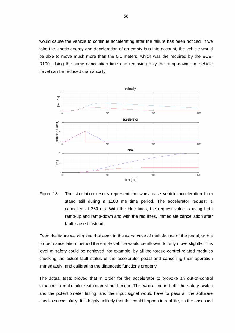
58
would cause the vehicle to continue accelerating after the failure has been noticed. If we
take the kinetic energy and deceleration of an empty bus into account, the vehicle would
be able to move much more than the 0.1 meters, which was the required by the ECE-
R100. Using the same cancelation time and removing only the ramp-down, the vehicle
travel can be reduced dramatically.
Figure 18. The simulation results represent the worst case vehicle acceleration from
stand still during a 1500 ms time period. The accelerator request is
cancelled at 250 ms. With the blue lines, the request value is using both
ramp-up and ramp-down and with the red lines, immediate cancellation after
fault is used instead.
From the figure we can see that even in the worst case of multi-failure of the pedal, with a
proper cancellation method the empty vehicle would be allowed to only move slightly. This
level of safety could be achieved, for example, by all the torque-control-related modules
checking the actual fault status of the accelerator pedal and cancelling their operation
immediately, and calibrating the diagnostic functions properly.
The actual tests proved that in order for the accelerator to provoke an out-of-control
situation, a multi-failure situation should occur. This would mean both the safety switch
and the potentiometer failing, and the input signal would have to pass all the software
checks successfully. It is highly unlikely that this could happen in real life, so the assessed

59
residual risk of this implementation was determined acceptable. In case the monitoring
application in the drive inverter is somehow not able to reset the inverter functionality, the
driver still has the regular brake system and an emergency stop switch to disable the
hybrid system.
In order to further enhance the system, the hardware should be upgraded first to support
real dual processing and process monitoring. The algorithms can easily be applied to both
of the inputs and the failing components can be voted out. This allows continued operation
while the driver is warned to take the vehicle to service for a closer check-up.
Of course, in a real emergency, the other cancelling means would be used by the driver,
but this review is done from the perspective of the worst case scenario per ECE-R100.
The conditions were interpreted so that the driver must not interfere with the pedal error
(UNECE 1997). In the case of a failing inverter, the failure may not be detected correctly
by the inverter control system, in this case, the HCU control system must automatically
send a stop signal to the inverter. It may not be possible to control any further problems,
but if for some reason this would not be enough to stop the failing inverter, the driver still
has an emergency button to stop and shutdown the system.
The signal test procedures involved an open-circuit or short-to-ground, short-to-plus and
static signal tests, and an interference tolerance test by adding varied amplitude PRBS on
top of the measured signal. The results of the tests concluded that with a single failure,
the ECE-R100 requirements will be fulfilled. Even with two simultaneous problems the
failures could be detected in most cases.

60
6 DISCUSSION
Trying to cover all the possible situations and add to the reliability of the system would
easily become costly. In a prototype vehicle meant mainly for research purposes, the level
of accepted risk is lower than in a bus meant for independent public use. In case a new
prototype bus was built for public use, different kind of equipment should be used
At the end of this project, the powertrain control and optimization of the hybrid system is
under development. Optimal changing and control of the hybrid modes has not yet been
fully implemented or automated. The research on fuel efficiency will provide feedback for
the mode optimization and algorithm design. This work succeeded, however, in providing
a modular software platform for the future development.
6.1 Instrumentation
Good instrumentation proved to be a surprisingly difficult and time consuming task. The
dash display should be able to present the vehicle status and a variety of messages for
the driver. The messages may relate to faults or instructions directing the use the vehicle
and some of them can be displayed with symbols. If it was possible, the symbols were
selected amongst the ISO 7000 series.
Although the nature of the hybrid system is highly complex, the user interface, its visual
outfit and presentation of the measured data and statuses, must be well thought. At a later
stage of the project a fully programmable instrument cluster from Enovation Controls was
acquired. While all the other CAN bus interfaces are predefined by their respective
manufactures, a custom set of J1939 PGNs were defined in order to send all the required
data to the instrument cluster. Right now the interface has the information required by the
regulations, and some additions for the driver to cope with the fault situations. This is also
a vitally important part of the safety plan. Special care must be taken that the user
interface logic is uniform with the user manual and that the operators are noted of any
important change. A commercial version of the instrumentation would require a thorough
investigation of the user requirements, basically interviewing drivers experienced with
EVs.

61
6.2 Safety aspects of the chosen equipment
The planning was not very effective in the beginning of the project. Some of the
equipment features were not carefully planned, some of the features did not work as
expected and some of the original equipment was not possible to investigate early enough
in the project. This led to improvised wiring on site, sometimes even to a change of
equipment or additions that were not planned originally.
Some of the preselected equipment did not fully conform to automotive design standards.
This was accepted as the vehicle is a prototype after all and the non-conforming
equipment can be replaced later, if necessary. Investigating these options would be a key
issue for possible later development. Adding an accelerator unit with dedicated
diagnostics and data bus communication should be considered. Looking at the system
architecture again with the presented results in mind, relaying the information with shorter
intervals would enhance the safety properties and simplify the software implementation.
A commercial vehicle requires a reliable electrical system. If this particular vehicle was in
full-time commercial use, some of the existing cabling should be replaced. In addition to
the regular electrical safety and voltage drop considerations with longer cables, an
automotive design not only requires chemical resistance and a large-scale heat tolerance
of the wire insulation, but also resistance to constant vibration and cable abrasion. Thus, a
premanufactured harness would be beneficial. In harnesses, the wires are banded
together, routed in conduits and placed in relevant cable supports to cancel the abrasive
effects of vibration. The project provided basic schematics that could be used to create
wiring harnesses for a retrofit vehicle. There is harness design software available to help
select all the necessary components. Currently, when the vehicle itself is 3D modelled, the
harnesses can be also routed and tried out in the model. A proper premeditation of the
wiring also helps to minimize the EMI problems that may otherwise create problems with
the control hardware as well. This should be considered in later developments.
6.3 Signal diagnostics
As all the input devices and their signals are subject to the possibility of a failure, care
should be taken on how to assess the input values. Lack of time and resources prevented
the use of more advanced methods, but they should be considered in the later revisions or
projects.

62
It would be advisable to use a diagnostic capable input and output system instead of the
digital inputs or outputs of the PLC, and diagnostic capable power sourcing. The digital
input signals could be read as analog signals or assessed by a separate window
comparator board. If, for example, all the signal states had known resistances, the signals
may be subjected to similar tests introduced in section 4.1. However, the basic digital
input system of the AC500 cannot reliably detect all the wiring failures. The inputs must be
protected with current limiting resistors. The switch inputs should either have a pull-down
resistor to ensure the input is driven to 0 volts when the switch is open, or to connect to
the ground though the switch with a pull-up activating the input (Kai 2010, 126). One of
the peripherals had a problem with unexpected intermittent triggering, but was not helped
by a pull-down resistor, and was only cured after modifying the firmware and application
filtering. Throughout the control system design, surge and load dump protection
requirements must be observed.
In automotive actuators, the voltage can be fed directly from the battery via a fuse and the
control unit pulls the voltage down. Nevertheless, the use of safe power sourcing can
monitor the current consumption and shut down the source in case of overcurrent. In both
cases the diagnostics can be implemented to the actuator by using current level
triggering.
The author suggests the development of a more capable and comprehensive diagnostic
system. In the beginning of the project, it was decided to completely omit the development
of a diagnostic system, but the necessity of diagnostics was admitted later. Only a simple
diagnostic system was designed to patch up critical safety issues. Now the implemented
signal plausibility checks do not cover the detection of abnormally fluctuating digital
signals. The author recommends making a separate input signal handling module, to filter
and process the signals. It should include a diagnostic module that will be constantly
observing input signal behavior. Each input variable should have an associated fault flag
that can be triggered in case of a detected signal error, so that any erroneous signal could
immediately cause the system to enter a safe state instead of potentially causing
unwanted actuator behavior.
It is to remember that the amount of diagnostics, safety and reliability required must be
determined by the risk assessment. The use of correctly rated equipment helps to lower
the costs involved, especially in production series.
63
6.4 Traction-motor-related problems
Even though software and hardware safety was ensured to cover all the thinkable
conditions, the chance that some equipment will fail and start acting erroneously still
persists. There was one good example of this during the test drives. When traveling at a
higher velocity requiring a field weakening operation of the PMSM motor, the control
software was correctly requesting zero torque from the traction motor inverters, but the
master inverter continued to apply torque. The problem was intermittent and could easily
be defeated by using the service brakes.
The operation of the traction motor inverter is possible to cancel using the stop signal
applied by a software component comparing the requested and applied torqued, or by an
emergency switch applicable by the driver. However, this might lead to another dangerous
situation as the voltage generated by the rotating PMSM motor will rise after the inverters
stop modulating. If in turn, the battery was disconnected from the circuit for whatever
reason, this would ultimately lead to a situation where the PMSM motor induces a very
high voltage, possibly damaging or destroying the inverters or other equipment not being
able to withstand the possibly high voltage. An automatic brake resistor is also installed,
but the location of the resistor poses another threat. The resistor unit is installed in a
sealed compartment made out of plywood with no ventilation to open air.
In a serious, life threatening situation, risking the equipment would be acceptable, as long
as the physical design of the equipment ensures that all the devices connected to the HV
can cause no additional danger, and that the insulation of the HV system tolerates high
enough voltages. Relocation of the brake resistor is advised because of the risk of fire
involved.
Although the driver is likely to notice any awkward behavior of the vehicle control system,
it is also important to give the driver an adequate warning of any detected dangerous
situation. The legal requirements demand that the driver is always able to use at least the
service brake to slow down and bring the vehicle to stop safely. The reason for this
particular problem was not fully confirmed, but could have been caused partly by a
misconfiguration of the resolver zero angle on the master inverter or an inverter software
bug. As the symptom is more or less intermittent, it will take time to find out the actual
cause of the problem.

64
6.5 Project management issues
When creating something completely new, it is common to just take some parts and
equipment, improvise and “just start building”. After a great idea, even if the equipment
and its functions seem to fully exist in one’s mind already, one needs to decide how to go
about prototyping it. At that point, a more or less abstract logical plan depicting the
functionality is made. Then the technical or physical plan must be created, telling how the
logical conditions are matched. These stages may be detected in just about any everyday
building process, when analyzed thoroughly. In any case, even primitive plans are
required in building a prototype or a product.
While the design processes themselves are iterative, many levels of iteration over the
process and project cycles can also be seen. Many times people refer to the iterative
nature of a specific development process, but iteration also happens between the
completed product models, when newer developments further enhance the features of the
previous models. In addition, prototyping processes may have changed or advanced.
There is a significant amount of scientific knowledge available today; one can plan
theoretically and model the system before starting to build it.
The author wants to bring attention to the fact that a loose higher-level logical or functional
planning of the equipment can be done any time, even at the beginning of a project. Even
if the equipment does not work yet, the equipment is in development or the equipment has
not been chosen. It is the technical architecture phase that must select the technical
solutions, and the module development phase that must enable the equipment to work as
it was designed to work in the beginning. The problems should only cause a part of the
project to slow down, and minor problems should not have any effect on higher-level
management.
It was sometimes confusing to discuss the project management-related issues. The same
people had to work with the lower-level modules, trying to get the technical features to
work, and they would plan the higher-level system controlling the modules as well. Some
of them worked with other projects and did not have full-time knowledge of what was
going on in the vehicle building in the workshop. Many times the module level progress
was slowed down by unexpected technical problems, which caused the overall progress
also to stall.
In the design and implementation phase, the management-emphasized approach favored
proceeding from the module development towards the main system, while the author tried
65
to see main system structure and then manage the development process from above.
This sometimes led to communication problems, which stemmed from the different
perspectives of the parties. The selection of the programming language is essential in
creating easily manageable code.
The author’s opinion is that the automation project work was begun rather late and the
management processes were inefficiently organized. The aim was first merely to create
control software for a research vehicle. Later on, the project had to also consider public
use, and the project planning was from then on processed semi-formally. This meant that
most of the older software had to be rewritten in favor of better functionality, modularity,
efficiency and reliability. Some of the changes in the equipment and software were
opposed for a long time and were discussed on several occasions. The actual changes
could have been made in less time than what it took to oppose said changes.
The author’s opinion is that the management and organizational problems caused
additional difficulties and delayed completion of this thesis. One of the greatest problems
was the management’s incapability to decide what the ultimate goal would be in terms of
the intended use of the bus, as this sets very different design requirements for the system.
Another major flaw was to forget the study of relevant regulations and the vehicle
technology, and avoid the thorough planning of the control system in the beginning. These
led to many technical and software related modifications in the later phases of the project.
One good example was the air compressor, which was selected using the wrong
specifications. Eventually it was discovered that the compressor output was not sufficient.
This would cause the air dryer purge function to not operate at all, and the air suspension
pressure to continuously stay close to the lower pressure limit. The replacement of the
compressor required a new cradle assembly, new coolant hoses, a new wiring harness
and new control software.
To be able to complete the design process in a truly comprehensive manner, it would
need more time and resources than were allocated for this project Based on experience,
the author would highly recommend that a project management strategy based on the V-
model be implemented in future development projects at LUT. The methods proposed by
the standards mentioned earlier in the work were found to be beneficial in the design
process. In a commercial project, more work resources would be required to properly
organize the operation in different processes, but following the guidelines is still
recommended for any smaller group constructing a prototype vehicle, as they help to build
a solid foundation for the design work.

66
REFERENCES
Bosch. 2002. Funktionsbeschreibung EDC15+ P120-VG2. Robert Bosch GmbH. 714
pages.
Cook, J.A. & Freudenberg, J.S. 2008 Controller Area Network (CAN). [Online]. Available:
http://www.eecs.umich.edu/courses/eecs461/doc/CAN_notes.pdf [Accessed 22 Nov
2016].
IEC/TR 61508-0. 2011. Functional safety of electrical/electronic/programmable electronic
safety-related systems. Part 0: Functional safety and IEC 61508. Helsinki: Suomen
Standardisoimisliitto. 29 pages.
Immonen, P., Lindh, P., Niemelä, H., Pyrhönen, J., Saikko, S. & Kasurinen, M. 2012.
Energy saving by hybridization of a city bus. 8 pages. DOI 10.1109/EPE.2014.6910855.
Kai, B. 2010. Elektronik in der Fahrzeugtechnik, 2nd edition. Wiesbaden: Vieweg+Teubner.
388 pages. ISBN: ISBN 978-3-8348-0548-5.
Kallberg, V. 2010 Linja-autojen paloturvallisuus Suomessa 2000-2009. [Online]. 50 pages.
Available: http://www.vtt.fi/publications/index.jsp [Accessed 15 Nov 2016]. ISBN 978-951-
38-7664-7.
Kasurinen, J. 2013. Ohjelmistotestauksen käsikirja. Jyväskylä: Docendo Oy. 204 pages.
ISBN: ISBN 978-952-5912-99-9.
Kokki, E. & Loponen, T. 2013. Bussipalot Suomessa 2010–2012 -hankkeen loppuraportti.
[Online]. 29 pages. Available: http://www.trafi.fi/tietopalvelut/julkaisut/
2013_julkaisut/bussipalot_2010-2012_-_loppuraportti [Accessed 16 Nov 2016].
Makkonen, R. 2015. Interviewed by Jani Alho, 17th August. Lappeenranta.
Montonen, J.-H. & Lindh, T. 2014. Analysis of Sensorless Traction Control System for
Electric Vehicle. 2014 16th European Conference on Power Electronics and Applications.
7 pages. 10.1109/EPE.2014.6911006.
Pressman, R.S. 2001. Software Engineering: A Practitioner's Approach, 5th edition. New
York: McGraw-Hill Education. 860 pages. ISBN: ISBN 0-07-365578-3.

67
Reif, K. & Dietsche, K.-H. 2014. Bosch Automotive Handbook, 9th edition. Karlsruhe:
Bentley Publishers. 1544 pages. ISBN: ISBN 978-0-8376-1732-9.
Schäuffele, J. & Zurawka, T. 2013. Automotive Software Engineering, 5th edition.
Wiesbaden: Springer Vieweg. 334 pages. ISBN: ISBN 978-3-8348-2470-7.
SFS-EN 61508-3. 2011. Functional safety of electrical/electronic/programmable electronic
safety-related systems. Part 3: Software requirements. Helsinki: Suomen
Standardisoimisliitto. 203 pages.
SFS-EN 61508-4. 2010 Functional safety of electrical/electronic/programmable electronic
safety-related systems. Part 4: Definitions and abbreviations. [Online]. 70 pages.
SFS-EN ISO 12100. 2010. Safety of machinery. General principles for design, risk
assessment and risk reduction. Helsinki: Suomen Standardisoimisliitto. 82 pages.
UNECE. 1997. Regulation 100. Geneva: United Nations Economic Commission for
Europe. 25 pages.
UNECE. 2013. Regulation 100 revision 2. Geneva: United Nations Economic Commission
for Europe. 82 pages.
VDO. 1996. Manual. VDO E-GAS II. [Online]. 90 pages. Available:
aftermarket.continental-corporation.com.au/files/0UZ16VKK0D/E-Gas_II.pdf [Accessed
2016 Nov 16].

Risk assessment related examples.
Example of identifying dangerous situations related to accelerator pedal system.
Below, an example of the risk assessment related to the dangerous situations
Method/tool
Analyst
Current version
Date
Method
Type
Hazard Equipment Hazardous situation Hazardous event
9 1 Use Driving Outside vehicle Road accident Accelerator Accelerator signal; pedal system malfunction Uncontrolled acceleration of the vehicle 9
9 2 Driving Cabin Passenger gets flung Accelerator Accelerator signal; pedal system malfunction Uncontrolled acceleration of the vehicle 9
9 3 Driving Cockpit Driver gets flung Accelerator Accelerator signal; pedal system malfunction Uncontrolled acceleration of the vehicle 9
risk graph
Ref.
no.
Ref.
no.
Risk assessment (hazard identification)
Checklists ISO 12100:2010 annex B, system architecture/functions
Life cycle
Extent
Sources
Machine
Hazard zoneTask Accident scenario
Requirements, specifications, preliminary design
CAMBUS hybrid bus
Use: operation 22.7.2015
1.0
JA
Risk estimation
x Preliminary risk estimation
Product: CAMBUS
Issued by: JA Black area = High risk
Date: 24.2.2015 Grey area = Medium risk
White are = Low risk
Severity
Se 0-4 5-7 8-10 11-13 14-15
Death, losing an eye or arm 4 SIL 2 SIL 2 SIL 2 SIL 3 SIL 3 ≥ 1 h 5 very high 5
Permanent, losing fingers 3 (OM) SIL 1 SIL 2 SIL 3 < 1 h … ≥ 24 h 4 likely 4
Reversible, medical attention 2 (OM) SIL 1 SIL 2 < 24 h … ≥ 2 w 3 possible 3 impossible 5
Reversible, first aid 1 (OM) SIL 1 < 2 w … ≥ 1 y 2 rarely 2 possible 3
< 1 y 1 negligible 1 likely 1
Ref Hazard Se Fr Pr Av Cl (SIL)
nro.
9 4 1 1 3 5 SIL 2
9 4 1 1 1 3 SIL 2
9 2 1 1 1 3 0
accelerator pedal subsystem failure
accelerator pedal subsystem failure
accelerator pedal subsystem failure
Class Cl (Fr+Pr+Av) Avoidance
AvPr
Probability
Fr
FrequencyConsequences
Typ.
Hzd.
No.
1 Road accident, casualties
2 Passenger gets flung
3 Driver gets flung
AP
PE
ND
IX I, 1
.
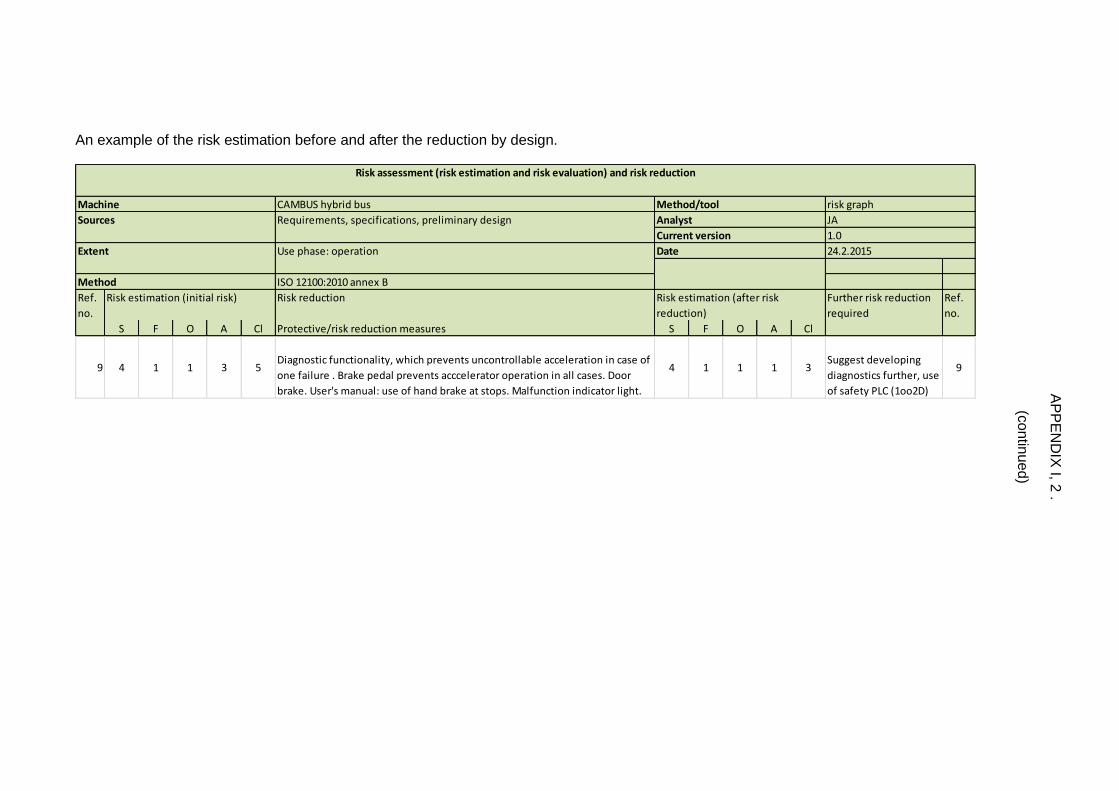
An example of the risk estimation before and after the reduction by design.
CAMBUS hybrid bus
ISO 12100:2010 annex B
Ref.
no.
Risk reduction Ref.
no.
S F O A Cl Protective/risk reduction measures S F O A Cl
9 4 1 1 3 5Diagnostic functionality, which prevents uncontrollable acceleration in case of
one failure . Brake pedal prevents acccelerator operation in all cases. Door
brake. User's manual: use of hand brake at stops. Malfunction indicator light.
4 1 1 1 3Suggest developing
diagnostics further, use
of safety PLC (1oo2D)
9
Risk assessment (risk estimation and risk evaluation) and risk reduction
Requirements, specifications, preliminary design
Use phase: operation
Method
Extent
Sources
Machine
24.2.2015Date
risk graph
JA
1.0Current version
Analyst
Method/tool
Risk estimation (initial risk) Risk estimation (after risk
reduction)
Further risk reduction
required
AP
PE
ND
IX I, 2
.
(co
ntin
ue
d)
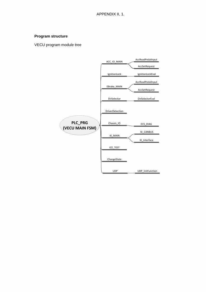
APPENDIX II, 1.
Program structure
VECU program module tree
PLC_PRG(VECU MAIN FSM)
IgnitionLock
ACC_IO_MAIN
EBrake_MAIN
DirSelector
DriverDetection
Chassis_IO
KI_MAIN
ICE_TEST
ChangeState
UDP
DirSelectorEval
IgnitionLockEval
AccReadPedalInput
AccSetRequest
AccReadPedalInput
AccSetRequest
ECS_DIAG
UDP_InitFunction
KI_Interface
KI_CANBUS
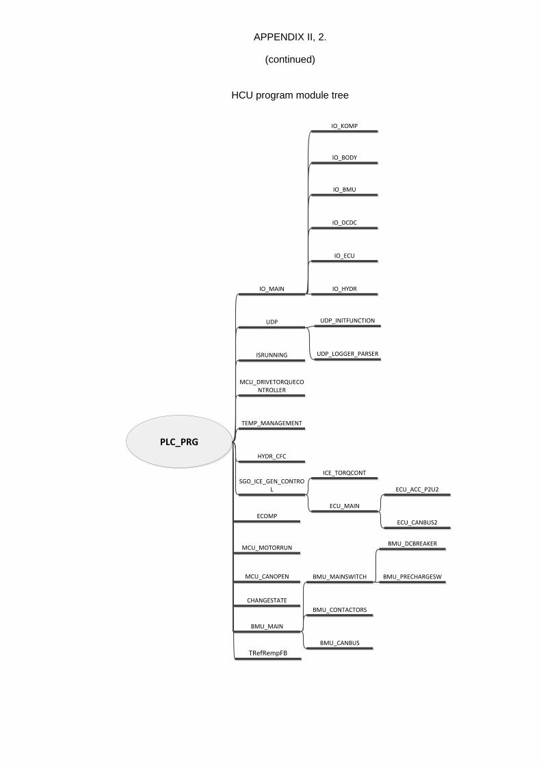
APPENDIX II, 2.
(continued)
HCU program module tree
PLC_PRG
IO_MAIN
MCU_CANOPEN
UDP
CHANGESTATE
ISRUNNING
BMU_MAIN
MCU_DRIVETORQUECONTROLLER
MCU_MOTORRUN
TEMP_MANAGEMENT
ECOMP
HYDR_CFC
SGO_ICE_GEN_CONTROL
IO_BMU
IO_DCDC
IO_ECU
IO_HYDR
IO_KOMP
IO_BODY
UDP_INITFUNCTION
BMU_CANBUS
BMU_CONTACTORS
BMU_MAINSWITCH
ICE_TORQCONT
ECU_MAIN
ECU_ACC_P2U2
ECU_CANBUS2
BMU_PRECHARGESW
BMU_DCBREAKER
UDP_LOGGER_PARSER
TRefRempFB

APPENDIX III, 1.
Test case presentation
Documentation of a test case of VECU/AccReadPedalInput
Device/Program: VECU
Component: AccReadPedalInput
Type: Function block
Description: Component of accelerator pedal implementation
Language (IEC 61131-3): ST
Version: 2016-03-10
Inputs
inputU INT (AI)
inputSK BOOL (DI)
inputKD BOOL (DI)
diag_run BOOL
Outputs
PedalPosition WORD
IdleSw BOOL
KickDown BOOL
fault BYTE
Used functions/function blocks/dependencies
ChangeState FUN
Functional description:
Included in the header of source code
Design specifications, flow chart

APPENDIX III, 2.
(continued)
Test date: 2016-03-10
Test type: blackbox, codesys
Test conducted by: JA
Test description:
verifying function according to functional description
verify operation with invalid inputs & BVS
Target description
PART 1
Verify processing of the analog and digital input signals
1. median filtering, implemented with OSCAT v3.3 library (61131-3, "no quarantees”) 2. scaling (see limit constants) and conditioning of the output signal (0-1000) 3. input signal BVS, illegal values (e.g. WORD >> INT) 4. verify digital signal input filtering and output
PART 2
Verify the diagnostic functions for determining interface device faults. Cases
1. toggling operation of diagnostic features 2. signal too low (AI, self-reseting) 3. signal too high (AI, self-reseting) 4. signal static (AI, self-reseting) 5. signal change rate too high (AI, self-reseting) 6. idle switch implausible (AI, DI)
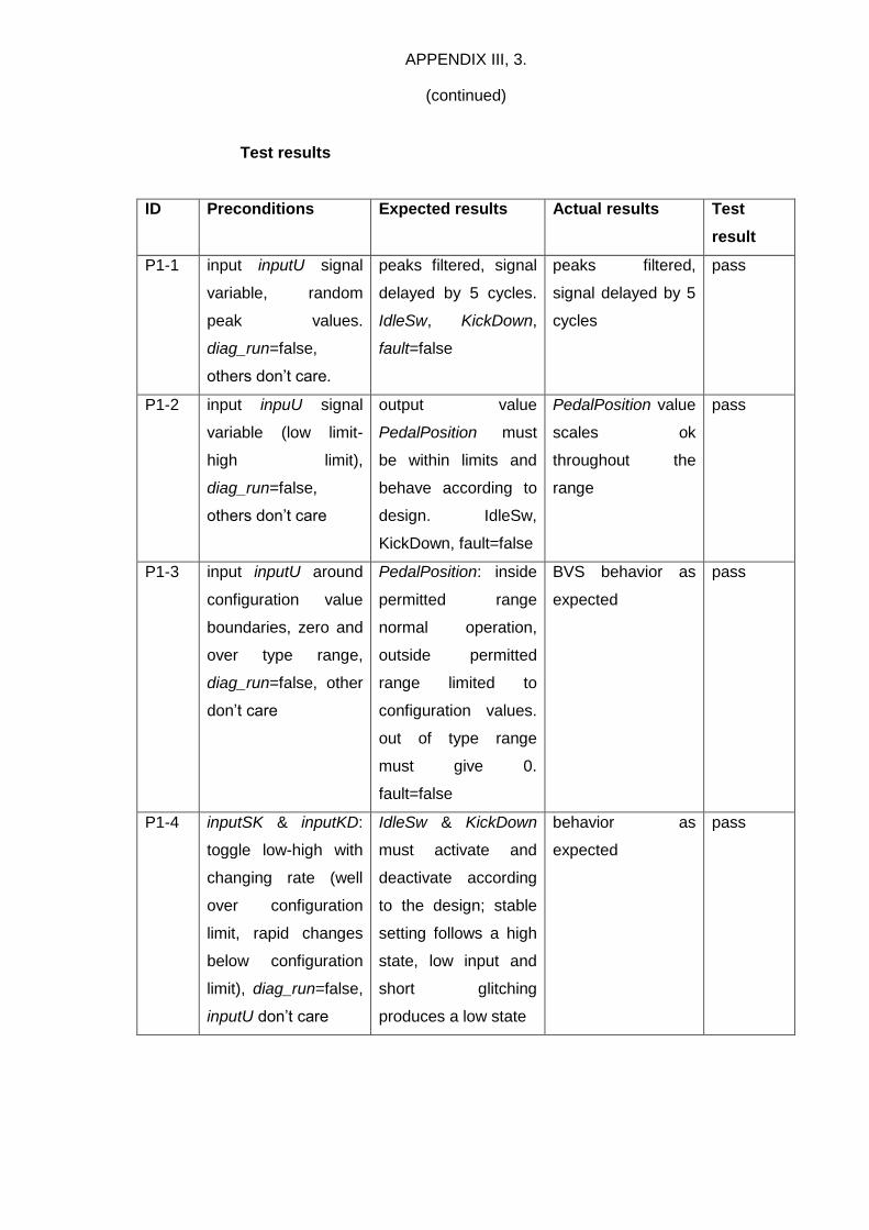
APPENDIX III, 3.
(continued)
Test results
ID Preconditions Expected results Actual results Test
result
P1-1 input inputU signal
variable, random
peak values.
diag_run=false,
others don’t care.
peaks filtered, signal
delayed by 5 cycles.
IdleSw, KickDown,
fault=false
peaks filtered,
signal delayed by 5
cycles
pass
P1-2 input inpuU signal
variable (low limit-
high limit),
diag_run=false,
others don’t care
output value
PedalPosition must
be within limits and
behave according to
design. IdleSw,
KickDown, fault=false
PedalPosition value
scales ok
throughout the
range
pass
P1-3 input inputU around
configuration value
boundaries, zero and
over type range,
diag_run=false, other
don’t care
PedalPosition: inside
permitted range
normal operation,
outside permitted
range limited to
configuration values.
out of type range
must give 0.
fault=false
BVS behavior as
expected
pass
P1-4 inputSK & inputKD:
toggle low-high with
changing rate (well
over configuration
limit, rapid changes
below configuration
limit), diag_run=false,
inputU don’t care
IdleSw & KickDown
must activate and
deactivate according
to the design; stable
setting follows a high
state, low input and
short glitching
produces a low state
behavior as
expected
pass

APPENDIX III, 4.
(continued)
ID Preconditions Expected results Actual results Test
result
P2-1 diag_run; toggle
diagnostic operation
on/off, monitor
operational state
diagnostic
functionality must
activate/deactivate
according to input
diag_run. After P2-2,
3 or 4 toggle off/on
must not reset fault
state.
diagnostic
functionality
activates/deactivates
according to input
diag_run. fault ok
pass
P2-2 diag_run=true;
permitted inputU ->
below low limit
configuration. hold
permitted value.
repeat x5
fault: “signal too low”.
PedalPosition=0,
IdleSw=true,
KickDown=false.
fault must reset /
resume normal
operation after a while
without error.
fault reports correct
error, pedal values
ok, resets as planned
pass
P2-3 diag_run=true;
permitted inputU ->
over high limit
configuration. hold
permitted value.
repeat x5
fault: “signal too high”.
PedalPosition=0,
IdleSw=true,
KickDown=false.
fault must reset /
resume normal
operation after a while
without error.
fault reports correct
error, pedal values
ok, resets as planned
pass
P2-4 diag_run=true;
inputU static in
permitted range with
inputs according to
configuration
fault: “signal static”.
PedalPosition=0,
IdleSw=true,
KickDown=false.
fault must reset /
resume normal
operation after a while
without error.
fault reports correct
error, pedal values
ok, resets as planned
pass

APPENDIX III, 5.
(continued)
ID Preconditions Expected results Actual results Test
result
P2-5 diag_run=true; inputU
behaves normally
with added PRBS
(see configuration
limits), inputSK as
per normal inputU
behavior
fault: “change rate too
high/implausible”,
PedalPosition=0,
IdleSw=true,
KickDown=false.
must reset / resume
normal operation after
a while without error.
fault reports
correct error,
resets as planned
pass
P2-6 diag_run=true,
inputSK behavior
does not match
inputU (see design &
configuration
constants)
fault: “idle switch
implausible”,
PedalPosition=0,
IdleSw=true,
KickDown=false.
fault must not reset /
resume normal
operation after a while
without error.
fault reports
correct error, fault
permanent
pass
Notes for further development
Calibration of the diagnostic parameters and limits suggested. No memory
kept for discovered intermittent faults.


![BUJPOBM$FOUFSGPSTTFTTNFOUJO)JHIFS&EVDBUJPO 2*:4†واتج التعلم محدثة/LO_Report... · Engineering Competence (UK-SPEC) [4], Conceiving-Designing-Implementing-Operating](https://static.fdocument.pub/doc/165x107/5ecdf666bfc69535540163c1/bujpobmfoufsgpsttfttnfoujojhifsevdbujpo-24-loreport.jpg)
