Design av Gasskydd för...
67
Design av Gasskydd för Friktionsomrörningssvetsningsmaskin Examensarbete på Svensk Kärnbränslehantering AB i Oskarshamn Henri Pehkonen Examensarbete LIU-IEI-TEK-A--14/01934—SE Institutionen för ekonomisk och industriell utveckling Maskinkonstruktion
Transcript of Design av Gasskydd för...
Design av Gasskydd för Friktionsomrörningssvetsningsmaskin
Examensarbete på Svensk Kärnbränslehantering AB i Oskarshamn
Henri Pehkonen
Examensarbete LIU-IEI-TEK-A--14/01934—SE
Institutionen för ekonomisk och industriell utveckling
Maskinkonstruktion

Design av Gasskydd för
friktionsomrörningssvetsningsmaskin
Design of Gas Shield for
Friction Stir Welding Machine
Henri Pehkonen
Handledare vid LiU: Peter Hallberg
Examinator vid LiU: Simon Schutte
Handledare vid SKB: Matts Björck
Examensarbete LIU-IEI-TEK-A--14/01934—SE
Institutionen för ekonomisk och industriell utveckling
Maskinkonstruktion

i
Abstract The research and development of the final disposal of the nuclear waste produced by the
nuclear power plants is an important work done by The Swedish Nuclear Fuel & Waste
Management Co. (SKB). As the demands on a final disposal increase the laboratory
equipment has to be better in order to do valid experiments. Research on how the copper
canister for the spent fuel will be manufactured and handled is done at the Canister laboratory
in Oskarshamn, Sweden. The work presented in this report was to design a new gas shield for
the friction stir welding machine at the laboratory. The welding machine seals the canisters
containing the spent fuel which are then transported to the final disposal 500 meter down in
basement rock. To minimize the amount of oxide particles in the weld zone SKB have to
design a better gas shield that should deliver the required atmosphere around the welding area.
The work contains a pre study phase where the important things to consider when designing
are collected. Then ideas are generated and concepts created for a new gas shield. These
concepts are evaluated by a pair wise comparison method in order to find the most promising
concept. The concept chosen is then detail designed to come as close to a manufacturable
design as possible.

ii
Sammanfattning Utvecklingen av ett slutförvar för det urbrända kärnbränslet som blir avfallsprodukten vid
framställning av energi via kärnkraft är ett viktigt arbete som drivs av Svensk
Kärnbränslehantering AB. Då kraven och bevisningen på huruvida ett slutförvar ska utföras
på ett säkert sätt måste experimenten och försöksutrustningen bli bättre för att generera
tillförlitliga resultat. Forskning om hur kopparkapseln för det urbrända kärnbränslet ska
konstrueras och hanteras pågår vid Kapsellaboratoriet i Oskarshamn. Arbetet som presenteras
i denna rapport tar upp konstruktionen av ett nytt gasskydd till
friktionsomrörningssvetsningsmaskinen på Kapsellaboratoriet. Svetsmaskinen försluter
kapslarna med radioaktivt avfall vilka sedan transporteras 500 meter ner i det svenska
urberget. För att minska mängden oxidpariklar kring svetsområdet måste SKB tillverka ett
nytt gasskydd vilket bör uppfylla de krav på atmosfären kring svetsområdet som finns.
Arbetet består av en forsknings- och informationssamlingsfas där viktiga aspekter och
problemområden hittas. Sedan genereras idéer och nya koncept på gasskydd fås fram.
Koncepten utvärderas parvis med metoden ”pair wise comparison” för att hitta det mest
lovande konceptet. Konceptet detaljkonstrueras och tillslut fås en design vilken är så nära
tillverkningsbar som möjligt.

iii
Acknowledgments This thesis is the last part of my education to achieve a Master of Science degree in
Mechanical Engineering at Linköping Technical University. This work had not turned out as
good as it did without the help of some people that I would like to thank here.
At SKB big thanks go out to my supervisors Matts Björck, Mikael Tigerström and Lars
Cerderqvist for great supervising and patience with questions as well as time for discussions.
At Maskinteknik gratitude is shown to Juha and Urpo Pehkonen for great ideas and solutions
to technical problems of all kind.
Henri Pehkonen
Oskarshamn, June 2014
iv
Table of contents Abstract ....................................................................................................................................... i
Sammanfattning ......................................................................................................................... ii
Acknowledgments ..................................................................................................................... iii
Table of figures ......................................................................................................................... vi
Table of diagrams and tables .................................................................................................... vii
1. Preface ................................................................................................................................ 1
2. Introduction ........................................................................................................................ 2
2.1 Friction stir welding ..................................................................................................... 2
2.2 Use of shielding gas ..................................................................................................... 3
2.3 Purpose and aim ........................................................................................................... 6
2.4 Work approach ............................................................................................................ 6
3. Expected operation environment and work approach ........................................................ 7
3.1 The industrial application ............................................................................................ 7
3.2 The laboratory application ........................................................................................... 7
4. Pre-study ............................................................................................................................. 8
4.1 Welding sequence description ..................................................................................... 8
4.2 Evaluation of the first and second version of gas shields .......................................... 13
4.3 Identified problem areas ............................................................................................ 15
4.4 Internal gas shield ...................................................................................................... 15
4.5 Flexibility ................................................................................................................... 16
4.6 State of the art ............................................................................................................ 16
4.7 Interviews with concerned parties ............................................................................. 19
4.8 Measurements on maximum temperatures around the welding area ........................ 20
4.9 Material movement in the lid ..................................................................................... 21
4.10 Centring of the canister .......................................................................................... 22
4.11 Conclusions of pre-study ....................................................................................... 22
4.12 Customer requirements .......................................................................................... 23
5. Function analysis .............................................................................................................. 24
6. Concept creation ............................................................................................................... 25
6.1 Concepts for sealing the welding spindle .................................................................. 25
6.2 Concepts for sealing against canister/other parts ...................................................... 27
7. Concept selection and detailed layout .............................................................................. 33

v
7.1 Evaluation .................................................................................................................. 33
7.2 Chosen concept .......................................................................................................... 33
7.3 Lifting the lid ............................................................................................................. 44
8. Failure Modes and Effect Analysis (FMEA) ................................................................... 45
9. Reflexions and further work with the design ................................................................... 46
10. Reference list ................................................................................................................. 47
9. Appendix .............................................................................................................................. 49
Appendix I - Gantt chart ....................................................................................................... 49
Appendix II - Function-Method-tree ................................................................................ 50
Appendix III – Concept evaluation ...................................................................................... 51
Appendix IV - Concepts for the machine in INKA.......................................................... 54
Appendix V - Drilling speed calculations for copper .......................................................... 56
Appendix VI - Thermal expansion of polycarbonate ........................................................... 56
Appendix VII – FME analysis ............................................................................................. 57
vi
Table of figures Figure 1: The KBS-3 method for the final disposal of the spent nuclear fuel. .......................... 2
Figure 2: The Friction Stir Welding process. ............................................................................. 3
Figure 3: Experiment on different cleaning degree and use of shield gas ................................. 4
Figure 4: Cross section view of an air welded sample.. ............................................................. 4
Figure 5: Amount of oxide particles depending on degree of cleanliness ................................. 5
Figure 6: Copper canister with its contents. ............................................................................... 8
Figure 7: Coordinate system of the machine. ............................................................................. 9
Figure 8: The welding machine from ESAB ............................................................................ 10
Figure 9: Drill used to machine a starting hole. ....................................................................... 10
Figure 10: The forming tool to the left and the welding tool to the right. ............................... 11
Figure 11: Welding tool mounted in the machine .................................................................... 12
Figure 12: Start and end point of the weld.. ............................................................................. 12
Figure 13: The first gas shield that existed.. ............................................................................ 13
Figure 14: Schematic view of the existing gas shield displaying the different chambers. ...... 14
Figure 15: A close up picture of two chambers in the existing gas shield .............................. 14
Figure 16: Welding tool comes down to the joint line from the starting position ................... 15
Figure 17: A cut trough of the canister with the lid assembled.. .............................................. 16
Figure 18: A big gas nozzle for TIG titanium welding and a standard size nozzle. ................ 17
Figure 19: Flood shield for TIG welding. ................................................................................ 17
Figure 20: Various trailing gas shields. .................................................................................... 18
Figure 21: Temperatures around the welding area.. ................................................................. 20
Figure 22: Material creep due to forces applied when entering the material with the probe. .. 21
Figure 23: The thermal expansion effects the welding has on the design... ............................. 22
Figure 24: Black box model ..................................................................................................... 24
Figure 25: Technical principle.. ............................................................................................... 24
Figure 26: Bellow concept. ...................................................................................................... 25
Figure 27: Big bellow concept ................................................................................................. 26
Figure 28: Sandblast concept in starting position.. .................................................................. 26
Figure 29: Sandblast concept in its deepest position ................................................................ 27
Figure 30: The ring that can be used as a sealing surface for the shield .................................. 27
Figure 31: The ring clamped in place ....................................................................................... 28
Figure 32: A solid cooling ring to provide better sealing surfaces for the gas shield. ............. 28
Figure 33: A sealing ring clamped on the canister ................................................................... 29
Figure 34: Air pillow to seal the space between the canister and machine base ...................... 29
Figure 35: The sealing ring bolted on to the machine base ...................................................... 30
Figure 36: Sliding doors concept ............................................................................................. 30
Figure 37: Papyrus concept ...................................................................................................... 31
Figure 38: Slider concept ......................................................................................................... 31
Figure 39: Zipper concept. ....................................................................................................... 32
Figure 40: Removal of drilling module .................................................................................... 34
Figure 41: The sealing around the head.. ................................................................................. 34
Figure 42: The chosen concept for further development. ........................................................ 35
Figure 43: Head plate mounted on the welding spindle. mounted to the head plate................ 36

vii
Figure 44: Frame for the larger end of the bellow to mount on.. ............................................. 36
Figure 45: The lower head shield mounted on the machine .................................................... 37
Figure 46: The left side shield. ................................................................................................. 37
Figure 47: The upper part of the head shield. .......................................................................... 38
Figure 48: Standing side brackets.. .......................................................................................... 39
Figure 49: Expansion allowance. ............................................................................................. 39
Figure 50: Cooling ring ............................................................................................................ 40
Figure 51: Bogie mount. ........................................................................................................... 40
Figure 52: Lower sealing ring bolted onto the machine base. ................................................. 41
Figure 53: A cut trough of the lower sealing ring. ................................................................... 41
Figure 54: Clearance for the canister to avoid damages to the seals. ....................................... 42
Figure 55: Movement of the top part of the machine...............................................................42
Figure 56: Placement for sensors and other equipment ........................................................... 43
Figure 57: Alternative method of centring the canister. ........................................................... 44
Figure 58: Lid lifting for internal gas shield ............................................................................ 44
Table of diagrams and tables Table 1: Required motions of the machine when welding ....................................................... 16

Preface
1
1. Preface In order to achieve a Master of Science degree in Mechanical Engineering with orientation
Machine design at Linköping Technical University this master thesis was performed as a
collaboration between The Swedish Nuclear Fuel & Waste Management Co at the canister
laboratory (Svensk Kärnbränslehantering AB, kapsellaboratoriet) and Maskinteknik AB, both
located in Oskarshamn, Sweden.
The Swedish Nuclear Fuel & Waste Management Co (SKB) is responsible for the nuclear
waste produced in by the time of writing 10 nuclear reactors in Sweden. Maskinteknik AB is
a mechanical workshop company that has more than 20 years of experience in machine design
and engineering. They have contributed with their knowledge in machine design and
manufacturing knowledge.
Introduction
2
2. Introduction When producing for example electrical energy with nuclear power the uranium fuel lasts for
about 5 years in the power plant before it is burned out. But the fuel is in no way harmless
when it is worn out, it is very hot and radioactive and if treated wrong deadly to humans. SKB
has been assigned by the owners of the nuclear facilities to handle the nuclear waste. With
handle is meant handling, transporting, storage and other activates related to the burned out
fuel. The fuel is held for about a year at the nuclear power plant in order to wait for the
radioactive decay to subside. The fuel is held in a water pool which acts both as protective
radiation shield and cooling medium for the fuel. Then the fuel is transported to an interim
storage, Clab in Oskarshamn, where the fuel is held in big water pools with the same purpose
as in the power plant. There the fuel is stored for about 30 years. The method that SKB have
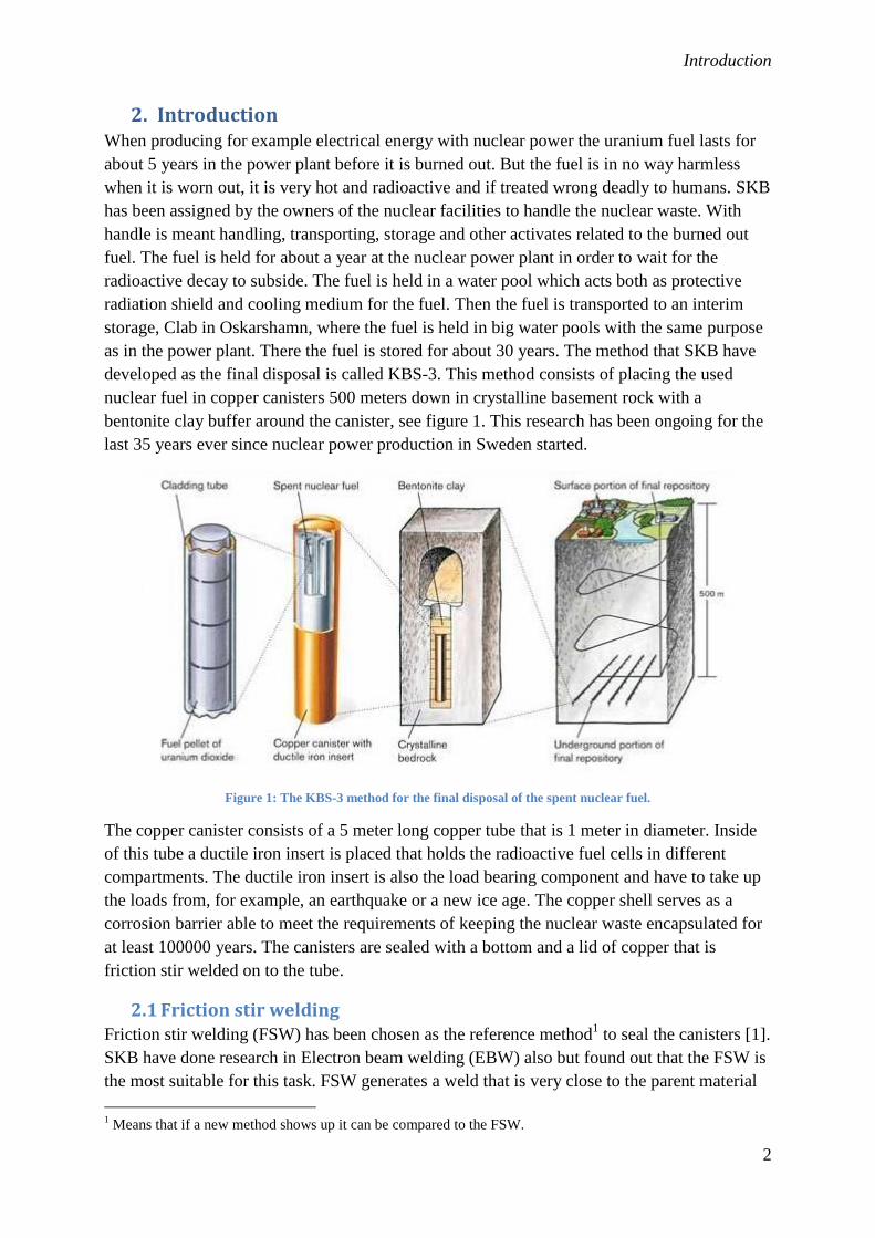
developed as the final disposal is called KBS-3. This method consists of placing the used
nuclear fuel in copper canisters 500 meters down in crystalline basement rock with a
bentonite clay buffer around the canister, see figure 1. This research has been ongoing for the
last 35 years ever since nuclear power production in Sweden started.
Figure 1: The KBS-3 method for the final disposal of the spent nuclear fuel.
The copper canister consists of a 5 meter long copper tube that is 1 meter in diameter. Inside
of this tube a ductile iron insert is placed that holds the radioactive fuel cells in different
compartments. The ductile iron insert is also the load bearing component and have to take up
the loads from, for example, an earthquake or a new ice age. The copper shell serves as a
corrosion barrier able to meet the requirements of keeping the nuclear waste encapsulated for
at least 100000 years. The canisters are sealed with a bottom and a lid of copper that is
friction stir welded on to the tube.
2.1 Friction stir welding Friction stir welding (FSW) has been chosen as the reference method
1 to seal the canisters [1].
SKB have done research in Electron beam welding (EBW) also but found out that the FSW is
the most suitable for this task. FSW generates a weld that is very close to the parent material
1 Means that if a new method shows up it can be compared to the FSW.

Introduction
3
in terms of microstructure with the same size grains and same structural set-up. FSW was
invented in the early 1990: s in England by The Welding Institute (TWI) and is used today
mainly for welding aluminum details for the aircraft, automotive, rail and space industry, see
figure 2.
Figure 2: The Friction Stir Welding process.
2.2 Use of shielding gas It is known that the use of shielding gas in the ordinary welding methods like TIG or
MIG/MAG welding improves the weld quality [2]. If air can reach the molten metal oxides
and nitrides can form and impair the quality of the weld both from a mechanical strength
aspect as well as from an aesthetic point of view. There is very little research on what effects
shielding gas has on the friction stir welding process but from a research at Aalto University
[3] it can be seen that shielding gas decreases the amount of oxide particles in the weld. The
FSW system is a solid state process and the joint surfaces will be oxidised prior to forming the
joint. When the welding tool passes through the joint it will disperse the oxide film on the
joint surfaces and produce oxide particles. If the amount of oxide particles is too high fracture
can occur around or on the site where oxide particles are located in a tensile stress test. [3]
The research showed that cleaning the surfaces properly and the use of shielding gas would
eliminate almost all oxide particles, see figures 3, 4 and 5.

Introduction
4
Figure 3: An overview of the experiment on different cleaning degree and use of shield gas, the probe was travelled
along the centreline of the groove in the direction of the white arrow. X in this test is 8mm. The resulting welds can be
seen in figures 4 and 5.
Figure 4: Cross section view of an air welded sample. Magnification of the marked area can be seen in figure 6.
X

Introduction
5
Figure 5: The effect on amount of oxide particles depending on degree of cleanliness of the surfaces before welding
and use of shielding gas during welding.
Samples not cleaned and no
use of shielding gas.
Samples cleaned but no use
of shielding gas.
Samples not cleaned but use
of shielding gas.
Samples cleaned and use of
shielding gas.

Introduction
6
2.3 Purpose and aim In order to eliminate the imperfections in terms of oxides in the joint a gas shield for the
welding process is needed. The oxygen levels are already reduced by an existing gas shield
system that will fill the compartment around the weld with argon and prevent oxygen from
getting in to or close to the welded area. This existing system does not work as good as
wanted and has to be redesigned. The goal is to design a gas shield system that meets the
requirements stated later in the report and if time permits do either small or full scale testing
on the setup.
2.4 Work approach
In order to achieve the best solution for the gas shield a systematic work method is
constructed and kept in mind when working with the thesis. A Gantt chart was done in the
beginning of the project to get an overview of the time available and how to arrange this into
the different tasks. The Gantt chart can be seen in appendix I.
Work method:
Collect information and try to understand the problem.
Interviews with concerned parties that have concrete input to the project.
Do a black box model and break down this into a technical principle.
Collect solutions for the different principles in a Function-method-tree (FM-tree).
Create concepts from the listed solutions in the FM-tree
Evaluate the concepts
Find one or two concepts to develop further to a detailed level.
In the end find the best solution for the gas shield.

Work approach
7
3. Expected operation environment and work approach
3.1 The industrial application The total amount of capsules that by the latest calculations has to be done is 6200, which
means 12400 welds needs to be done [4]. The calculated number of capsules will be enough
to encapsulate all waste that have been produced and the waste that will be produced until the
expected settlement of the current nuclear power production plants in Sweden. The
encapsulation process will continue for about 50-60 years in order to allow the radioactivity to
decay. The gas shield around the welding area should be easy to use and deliver the same
atmosphere for the weld each time. The first 6200 welds of the bottom of the canister will be
performed in a common industrial environment, called the canister factory, and the other 6200
will be performed by robots in a radiation secure compartment in the encapsulation plant.
None of these facilities mentioned above haven’t by the time of writing been built but the
development and design of these is ongoing.
3.2 The laboratory application The main objective of this thesis though is to improve the gas shield for the existing welding
machine located in the canister laboratory. The final machine needed in the encapsulation
plant has to be able to withstand high radioactivity and be operated remotely so the design
will differ from the laboratory machine. The machine in the canister factory will have the
same design as the one in the encapsulation plant but without the radioactive-safe extra
applications. The laboratory machine have and will be used for many experiments so when
designing a new gas shield aspects like easy installation and adaptability should be considered
as well. If time allows designs of the gas shield for the industrial machine could be
considered.

Pre-study
8
4. Pre-study
4.1 Welding sequence description The welding method is easiest described with some illustrative pictures.
In figure 6 a schematic picture of the copper canister and its contents can be seen. The ductile
iron insert, (1) in figure 6 is placed in the canister and the fuel cells are placed in the
compartments in the iron insert. Then the lid, (2) in figure 6, is mounted in place to seal the
canister.
Figure 6: Copper canister with its contents.

Pre-study
9
The different degrees of freedom of the welding machine can be seen in figure 7. The welding
tool that joins the tube and the lid together is located at the (1) in figure 7, a more detailed
description of the welding tool comes later in this chapter.
Figure 7: Coordinate system of the machine. In figure A and B a side respectively a top view of the machine is
displayed.
Y
S Z
X
1
1
A
B

Pre-study
10
The copper canister is placed vertically in the welding machine and clamped with twelve
hydraulic actuators, located at (1), but not visible, in figure 8, to hold the canister in place
while welding. Then a force is applied downwards by the top part of the machine with three
hydraulic actuators located at (2) in figure 8, this prevents the lid from rotating when welding.
Figure 8: The welding machine from ESAB with the upper part of a copper canister in the middle.
When the canister is in place a starting hole is drilled in the lid to help the welding tool
penetrate deep into the material. This operation is done by an external drilling platform
located next to the welding spindle, see figure 9.
Figure 9: Drill used to machine a starting hole.
2
1
Pre-study
11
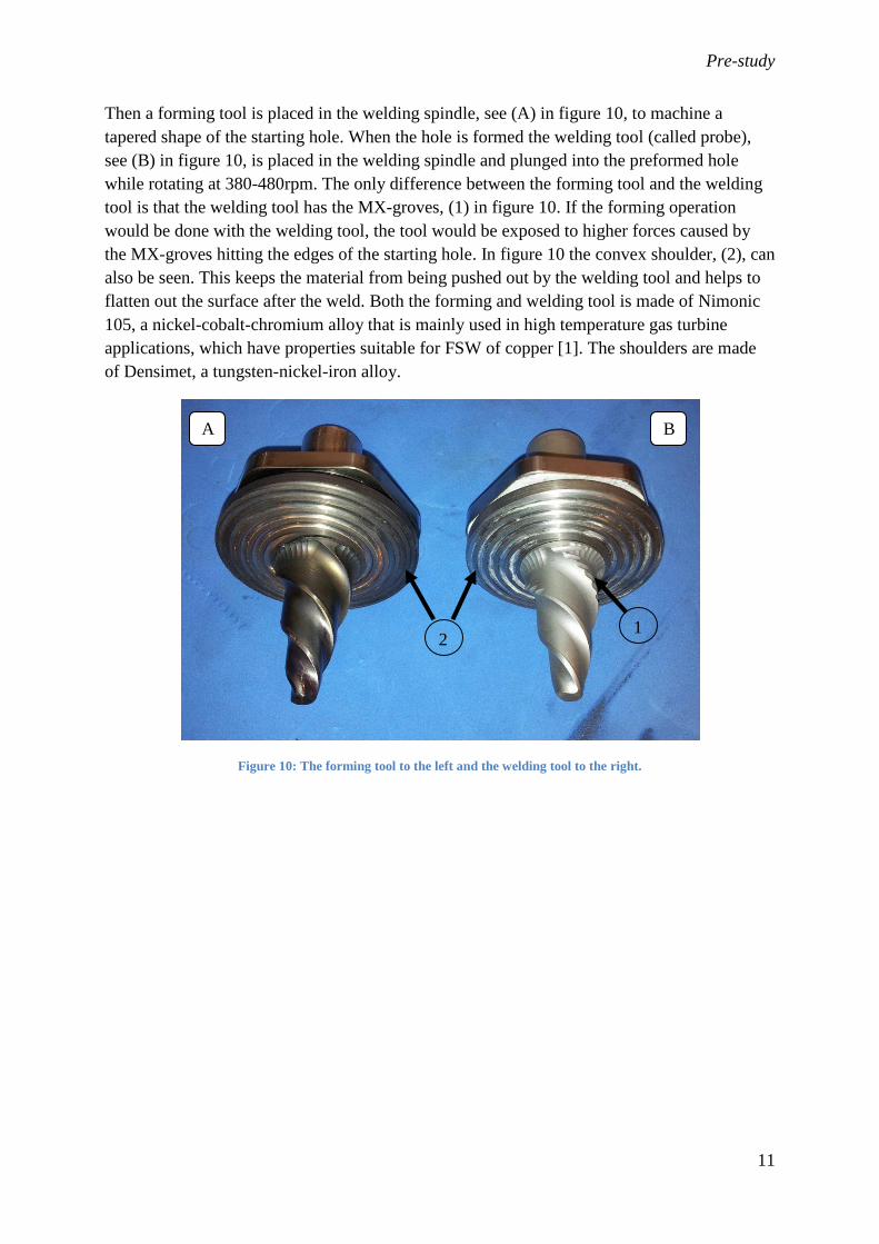
Then a forming tool is placed in the welding spindle, see (A) in figure 10, to machine a
tapered shape of the starting hole. When the hole is formed the welding tool (called probe),
see (B) in figure 10, is placed in the welding spindle and plunged into the preformed hole
while rotating at 380-480rpm. The only difference between the forming tool and the welding
tool is that the welding tool has the MX-groves, (1) in figure 10. If the forming operation
would be done with the welding tool, the tool would be exposed to higher forces caused by
the MX-groves hitting the edges of the starting hole. In figure 10 the convex shoulder, (2), can
also be seen. This keeps the material from being pushed out by the welding tool and helps to
flatten out the surface after the weld. Both the forming and welding tool is made of Nimonic
105, a nickel-cobalt-chromium alloy that is mainly used in high temperature gas turbine
applications, which have properties suitable for FSW of copper [1]. The shoulders are made
of Densimet, a tungsten-nickel-iron alloy.
Figure 10: The forming tool to the left and the welding tool to the right.
A B
2 1

Pre-study
12
Figure 11 shows the welding tool and shoulder are mounted in the machine. When operating,
the machine rotates around the canister, X-axis in figure 7, joining the tube and lid together.
The area around the welding tool and spindle is referred to as the welding head later in the
report.
Figure 11: Welding tool mounted in the machine
As mentioned earlier, the starting hole is drilled some distance up from the joint line on the lid
because if something goes wrong with the start hole or at first centimetres of welding the
process can be aborted and the lid can be changed to a new one. If the start point would be
located at the joint line and something would go wrong the whole canister would have to be
replaced. The end point of the weld is similar to the starting point located up on the lid, this
because when removing the welding tool a hole is left in the material, see figure 12. This hole
and the starting point are machined away as well as a couple of millimetres radially of the end
of the canister, removing the outermost part of the weld, for example the welding flash, also
seen in figure 12.
Figure 12: Start and end point of the weld. Here it can be seen that when the machine has joined together the tube and
lid the path of the tool overlaps the path in the beginning making a complete weld at the joint line.

Pre-study
13
4.2 Evaluation of the first and second version of gas shields As delivered, the friction stir welding machine from ESAB had no shield gas system and this
had to be retro-fitted in order to reduce the amount of oxygen particles in the weld. There
have been two different designs of gas shields on the machine the past couple of years.
These designs will be recaptured here to evaluate the sting points and weaknesses of each
design. The first version of gas shield consisted of two curved sheet metal pieces that slid
along a lip mounted on the canister, see figure 13. This concept did not withstand the heat
generated from the weld, the plate clamped between the cooling clamps and the top of the lid,
(1) in figure 13, bent. The reason for is believed to be the use of too thin sheet metal. The
sealing material in the joints between some of the different parts melted due to improper
material, nylon, selection.
Figure 13: The first gas shield that existed. Here the top sheet metal, (1), was clamped between the upper
part of the machine and the lid. On this sheet metal the rounded cover plate, (2), slid on to allow rotation
around the canister. The welding spindle could also move up and down with a smaller plate, (3), which slid
in grooves on the rounded plate.
The second gas shield and the one used on the machine today consists of one chamber at the
welding spindle as well as four other chambers, see figure 14 and 15, distributed around the
canister to cover the circumference of the joint line.
1
2 3

Pre-study
14
Figure 14: Schematic view of the existing gas shield displaying the different chambers.
Figure 15: A close up picture of two chambers in the existing gas shield. Here can be seen that the different chambers
are sealed to each other with tape making a highly inconsistent seal.
When studying the existing gas shield conclusions can be made of what needs to be improved
in order to fulfil the requirements. The gas chamber around the spindle is not functioning
satisfactory because the chamber is not sealing against the canister surface properly. Also, the
sealing lips that should do this have big gaps here and there allowing air to come in to the
chamber. The transition to the nearest surrounding chambers is not air tight, these also have
gaps that allow air into the chambers. Another problem with the spindle gas shield is that it
does not have contact with the capsule when inserting the probe in the starting hole.
The positive aspects of the existing shield are that the rubber lip that seals all the chambers
against the canister withstands the heat of the welding area good. The parts that slide over the
weld are made of silicon rubber and do not melt thus that material could be used as sealing in
an improved concept.

Pre-study
15
4.3 Identified problem areas An important aspect to consider is that the joint line needs to be protected by shielding gas the
whole time when welding. Once the welding starts it heats up the material and when the
machine travels along the circumference the joint line that is next to the start position gets hot,
see figure 16. It is important to keep the not yet welded areas free from oxide grow. The
oxides start to form when the temperature of the material exceeds approximately 100° Celsius
[5]. Thus the shield has to cover the whole joint line around the canister in order to prevent
oxide growth as much as possible.
Figure 16: When the welding tool comes down to the joint line from the starting position the area marked with the
ellipse gets hot and has to be isolated from oxygen.
4.4 Internal gas shield Currently there are experiments ongoing to determine the effects of an internal gas shield on
oxide formation, mainly around the root area of the weld, see (1) in figure 17. The method for
the internal gas shield would consist of filling the inside of the canister with inert gas to
prevent weld contamination. If not filled with gas the oxygen could contaminate the weld
from the inside when the temperature of the canister rises and pressure inside the canister gets
higher. This would maybe require a higher pressure in the external gas shield, thus maybe
requiring a more complex design.
This new design of the gas shield should allow the inside to be flushed with gas. This could be
done by lifting the lid from the canister while the gas shield is engaged and then start to flush,
see figure 17. When the oxygen content is at low enough levels the lid is lowered onto the
canister while keeping the shield engaged at all times. And after this control the oxygen
content in the external gas compartment.

Pre-study
16
Figure 17: A cut trough of the canister with the lid assembled. To fill the inside of the canister the lid would have to be
lifted approx 75mm in order to clear the alignment face on the lid.
For the fastest flushing of the inside of the canister the lid would have to be raised approx
75mm in order to have a clear path in to the canister. But the height required is not available
in the laboratory machine used today without major rebuilding of the machine. The lid can
today be lifted approx 20mm and the concept detailed here for the internal gas shield could be
tested with a redesigned lid for that experiment.
4.5 Flexibility When the machine is operating there is several parts that move and has to be considered when
designing the gas shield. With reference to figure 6 the different motions of the machine when
welding can be described.
Table 1: Required motions of the machine when welding
Axis X Y Z S
Distance Rotate approx. 480° 90mm 90mm ±20mm Off center
And on top of this the earlier mentioned internal gas shield should be able to perform so that
gives an extra degree of freedom when the lid has to be able to lift 20mm while the gas shield
is engaged.
4.6 State of the art State of the art studies of this kind of applications is hard to find because this is a unique
machine. Information can be found from what ordinary welding machines like TIG or
MIG/MAG techniques require getting an adequate welding result. TIG stands for Tungsten
Inert Gas and MIG/MAG for Metal Inert Gas/Metal Active Gas welding and is two of the
three most common ways of traditional metal welding.
ESAB states that it is important to check that the welding equipment has the right amount of
gas flow and high enough pressure in the gas tubes. Also leakages and air diffusion into the
gas hoses should be checked [2]. When welding titanium some similarities may be found
71mm
1

Pre-study
17
when comparing it to FSW copper. The titanium should to be in an oxygen-free surrounding
during welding as well as after to avoid embrittlement. If the titanium is exposed to a
temperature above 520° C oxygen can diffuse into the material and embrittle it. When TIG-
welding titanium either using a bigger gas nozzle, seen in figure 18, or the use of a
flooding/trailing gas shield, seen in figure 19, is common [2].
Figure 18: A big gas nozzle for TIG titanium welding on the left and a standard size nozzle on the right.
Figure 19: Flood shield for TIG welding to prevent oxygen from entering the weld during cool down.

Pre-study
18
There are some more variants on trailing gas shields on the market for ordinary welding
methods. Some shields are seen in figure 20, which consists of a similar chamber that exists
on the machine today with silicone rubber sealing along the edges of the shield [6].
Figure 20: Various trailing gas shields that will prevent oxidisation of the weld and its surroundings.
The shields here have a sinter metal plate on the inside of the shield that disperses the gas
evenly in the chamber. The sintered steel is a porous material which creates a steady and
laminar flow of gas inside the chamber.

Pre-study
19
4.7 Interviews with concerned parties
Encapsulation plant - Meeting with Peter Ohlsson, project leader.
Important aspects:
The thoughts from him according the gas shield were of course mainly directed of what to
think about when designing a shield for the encapsulation plant. Here the material selection is
an important aspect to consider, using materials that withstand high radiation levels, for
example plastics are not suitable since they will age rapidly and become brittle.
Control engineer from LIU, Isak Nielsen
Other stakeholders of the project are control engineers from Linköping University who
develops a closed loop controller suitable for the welding process. The main aspects to
consider according to the control engineer Isak Nielsen, LIU, was to have much space around
the welding spindle to be able to put in new sensors and cameras to better control the welding
process. Two linear variable differential transformer sensors (LVDT) should be installed to
measure the distance from the welding tool to the canister as close to the tool as possible. The
two sensors would be placed vertically beside each other so that one of them travels along the
lids surface and the other on the canisters surface to better monitor the process and possible
deviations.
Maskinteknik in Oskarshamn
The new design should also of course be manufacturable and here the company Maskinteknik
in Oskarshamn supports with knowledge in this part and their point of view of the problem
should also be included. The ideas and aspects to consider according to Maskinteknik were to
make the shield around the spindle large to allow more sensors and equipment to be placed
near the probe. Another aspect was to consider removing the drilling unit in order to gain
space and to ease the design of the shield.
Staff at canister laboratory
Discussions with the staff that use the welding machine at the canister laboratory was carried
out whenever needed and when questions occurred.
Some of the important thoughts from the staff where concerning the space available for a new
gas shield and oxygen levels in the shield when operating. The space around the welding
spindle is small and the shield should either be compact or easy to remove to allow service
and tool changes to be made.
Experiments on how much oxygen is allowed in the welding compartment to get an
acceptable weld has been performed earlier at the canister laboratory. The results from these
experiments have been studied and it stated that if the oxygen level in the shield could be kept
at least below 100 ppm it should result in a weld that meet the demands on imperfections
caused by oxygen in the weld [2].

Pre-study
20
4.8 Measurements on maximum temperatures around the welding area This experiment is important to conduct to get values on the maximum temperatures that
occur around the welding area. As mentioned earlier the first gas shield that existed had
problems withstanding the heat generated by the welding operation. The maximum
temperatures from the experiments will then be used as reference when designing the seal and
other parts of the shield.
Measurements on the temperatures were taken when welding a short distance around the
canister. The temperatures presented here should be seen as minimum temperatures because
welding a longer distance and time will eventually heat up the whole canister more than just
this short part. Measurements were taken both with a surface contact temperature probe and
an infra-red camera during the welding process.
The temperature in the nearby surrounding of the weld is described in figure 21 below.
Figure 21: Temperatures around the welding area. The temperatures on the copper surfaces where measured with the
contact probe while the temperatures on the cooling blocks where measured with the IR-camera.
Temperatures on the probe and shoulder are about 800°C [8] and decreases rapidly when
moving away from the welding area. Just outside the shoulder temperatures around 300-
400°C occur. 170mm down from the joint line temperatures of around 130°C is present.
300-400°C
30°C
70°C
130°C
170mm
Cooling blocks

Pre-study
21
On the top of the lid where the cooling blocks are in contact the temperature is around 60°C
and on the upper part of the cooling blocks the temperature is around 30°C.
Air temperatures around the spindle where also investigated on a short weld. These
temperatures are not valid as design parameters because when welding a complete canister
everything gets hotter. A thermocouple where placed inside the gas chamber of the welding
spindle. The sensor was is placed 100mm to the left of the tool tip, 60 mm down from the tool
tip and when welding, 15mm out from the canisters surface. The temperatures in this place
reached a maximum of around 60 °C which is fairly low, probably because of the flow of cold
argon inside the chamber.
4.9 Material movement in the lid When the probe and shoulder is plunged into the lid the relatively soft copper moves around
due to the forces applied. This movement is preferred kept as low as possible to better control
the welding process. As seen in figure 22, the copper sometimes moves much when entering
the material. This motion of the material is not so severe because it is machined away, but it
complicates controlling.
Figure 22: Material creep due to forces applied when entering the material with the probe.
When the probe travels along the circumference of the canister the material near the probe
gets hot and expands. The cooling clamps that apply pressure downwards against the have
gaps between the clamps allowing material to creep in these areas. Also the cooling clamps
are mounted in a bogie design and this do not cancel the movements of the material, instead it
suspends the movement of the lid, see figure 23. If material movement could be kept at a
minimum it would ease controlling of the welding operation. Contact has been made with
Jörgen Säll at ESAB who is the manufacturer of the machine and their explanation of why the
bogie design is used is to secure good abutment around the whole surface.

Pre-study
22
Figure 23: The thermal expansion effects the welding has on the design. When the probe travels along the canister the
surroundings gets hot and expands causing the cooling blocks to lift slightly and allowing material to creep up. The
hot probe is at the red oval and travels to the left. The rectangular blue areas are cold areas of the canister.
4.10 Centring of the canister Another problem that exists which does not have so much relation with the gas shield is the
centring of the canister in the machine. The canister is preferably mounted in the exact centre
of the machine simplifying the control of the welding sequence. The centring of the canister
today is difficult and takes a lot of time. Ideas on how to ease the centring could also be
integrated with the new gas shield design.
4.11 Conclusions of pre-study The pre study resulted in different demands and things to consider when designing a new gas
shield.
Flexibility of the shield has to be good because the spindle should be able to move in three
directions with the shield engaged.
In and out of the canister
Up and down along the canister
Rotate around the canister
When the shield is engaged the lid should be able to lift at least 20mm to allow the inside of
the canister to be flushed with gas (internal gas shield). The temperature around the welding
area is high and is a limiting factor for designing a shield, the choice of material must be done
in a way that it can handle the heat levels present. The shield in the laboratory machine should
be easy to handle and install/remove since it is used in many tests. The machine has very
little motion reserve in the Z-axis and S-axis direction. The Z-axis cradle extends longer on
the left side than on the right side of the machine spindle making the space between the
machine and capsule tight.
Pre-study
23
4.12 Customer requirements The pre-study resulted in defined customer requirements listed below that should be fulfilled
with the new gas shield.
The oxygen content in the welding area should be kept at least below 100 ppm.
The gas shield should be easy to use, with fast installation and removal.
Flexible in terms of that it should be able to follow the welding tools position along
the canister. Problems occur at the start and end points where the welding tool moves
in the Z- and Y-axes along the canister.
Flexible in terms of sealing ability against the welded surface. There can occur some
welding flash, see figure 12, when the shoulder travels along the canister which the
gas shield should seal around.
The shield should have outputs for different sensors to measure oxygen content and
pressure during a weld
Sensors for measuring the position of the probe should be included in or around the
shield.
The shield and seals may be exposed to high temperatures that have to be considered
when designing.
Thoughts on how to make the shield work together with an automated welding
machine in the radiation safe compartment when sealing the tube with its radioactive
contents in the encapsulation plant should also be included.

Function analysis
24
5. Function analysis A black box model, see figure 24, and a technical principle where done to get a better
structure of all the different possible solutions of the problem and to make the construction
work easier. The box in the black box method can be separated into a technical principle
where the function is described more detailed, see figure 25. From this a function tree where
created to list possible solutions on how to manage the different steps in the technical
principle. The function tree was constructed by brainstorming and state of the art studies on
similar applications in the welding industry. Also the most relevant ideas from the interviews
with concerned parties where included. The function tree can be seen in appendix II.
Figure 24: Black box model
Figure 25: Technical principle. The framed boxes are parts of a possible internal gas shield.

Concept creation
25
6. Concept creation From the function tree different concepts where created as possible solutions for a gas shield.
Some of the most realistic concepts and the ones possible to implement on this machine are
listed here below with a short description. Chapter 6.1 contains concepts for shield designs
around the welding spindle and how to allow the motions required. In 6.2 concepts on how
the shield design could look like on the other parts around the canister is presented. Concepts
implementable for the gas shield for the welding machine in the encapsulation plant can be
seen in appendix IV.
6.1 Concepts for sealing the welding spindle
Bellow concept
This concept consists of a bellow that is put around the machine head. A frame around the
base plate of the machine head is mounted and on this frame the bellow is installed. The other
end of the bellow then mounts on the gas shield and allows the head to move in any direction
while sealing around the head, see figure 26. This concept requires that the shield surrounding
the canister is moved by external brackets and not by the head itself.
Figure 26: Bellow concept with the bellow in black and the see through plates in smoked red. The grey parts are metal
of some kind. The machine cradles are hidden for better visibility.
Big bellow concept with removed drill module
The idea is to relocate or to remove the drilling module that is positioned next to the welding
head. The shield and bellow gets complex if the drilling module is kept in the current position.
Removing the module allows modifications to be done on the cradle where the machine head
sits and simplifies construction of the shield. The bellow can be bigger and this frees up space
around the head, see figure 27.

Concept creation
26
Figure 27: Big bellow concept with the bellow in black and the transparent plastic shields in yellow.
Sandblast concept
This concept involves a telescopic ring that is placed on the machine head seen in figure 28.
The ring is stationary when the tool rotates and fits into a rubber hole that is mounted on the
shield that surrounds the canister. This rubber hole will seal against the ring and will allow the
head to move in Z-axis direction. The vertical movement is provided by a plate that slides
along the shield with sealing’s around the edges.
Figure 28: Sandblast concept in starting position. In figure 29 the concept can be seen in its deepest position. Here the
cover shields around the canister are hidden for better visibility.

Concept creation
27
Figure 29: Sandblast concept in its deepest position
6.2 Concepts for sealing against canister/other parts
The ring
The distance between the starting hole and the top of the lid is small as seen in figure 12.
Providing a proper seal in these parts is difficult. The area near the top of the lid gets very hot
which complicates the task further. A solution is to provide a smooth surface higher up on the
cooling blocks where space is ample and the temperature is lower. A ring of a suitable
material is clamped between the cooling blocks and the top of the lid and extends some
distance up near the cooling blocks, see figures 30 and 31. It is assumed that the joint between
the ring and lid will seal when 35 tonnes of clamping force is applied.
Figure 30: The ring that can be used as a sealing surface for the shield
Concept creation
28
Figure 31: The ring clamped in place
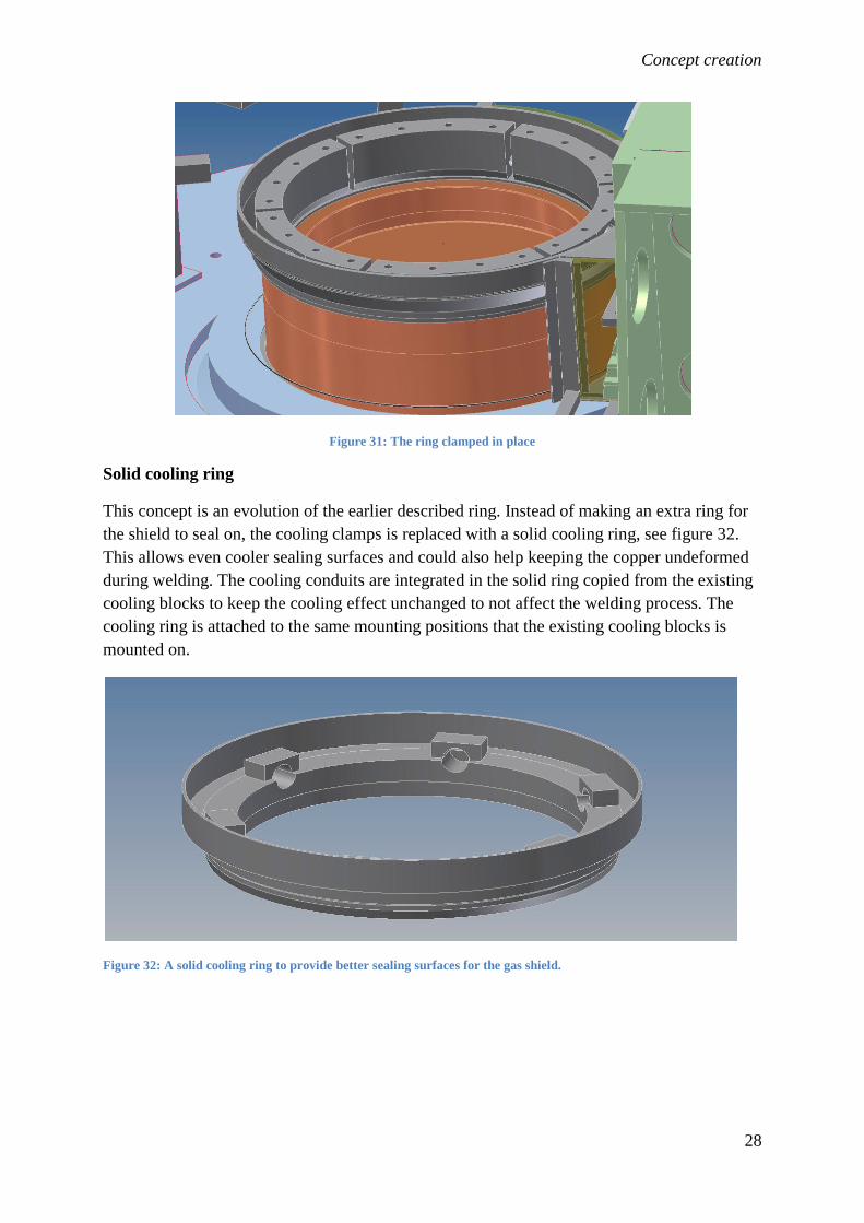
Solid cooling ring
This concept is an evolution of the earlier described ring. Instead of making an extra ring for
the shield to seal on, the cooling clamps is replaced with a solid cooling ring, see figure 32.
This allows even cooler sealing surfaces and could also help keeping the copper undeformed
during welding. The cooling conduits are integrated in the solid ring copied from the existing
cooling blocks to keep the cooling effect unchanged to not affect the welding process. The
cooling ring is attached to the same mounting positions that the existing cooling blocks is
mounted on.
Figure 32: A solid cooling ring to provide better sealing surfaces for the gas shield.

Concept creation
29
Sealing lip clamped on the canister
A sealing lip that is clamped around the canister is a way to seal the lower part of the shield,
visualised in figure 33. This lip can consist of two halves or a single ring that could be
tightened by a strap similar to the ones used in truck bed sides on trailers and lorries [14].
Figure 33: A sealing ring clamped on the canister
Air pillow
The surface on the canister gets hot and it is preferred to have the sealing and other part as far
away as possible from the hot areas. If the sealing lip mentioned in the earlier concept could
be moved down on the machine base a much lower temperature would be present. Then a seal
around the canister and machine base would be needed. This could be done with an air pillow
which fills up the space between the machine base and canister seen in figure 34. Similar
solutions are used in the welding industry for sealing pipe ends, which are designed to
withstand high temperatures.
Figure 34: Air pillow to seal the space between the canister and machine base
Together with the air pillow seal a sealing ring is bolted on the machine base which provides a
sealing lip for the shields around the canister to slide on, see figure 35. This concept does not
have components that are fastened to the canister manually. All seals against the canister are
static and can be operated remotely.

Concept creation
30
Figure 35: The sealing ring bolted on to the machine base
Sliding doors
This concept consists of two or three doors (plates) that would slide in a rail mounted on the
ring. There would be a sealing lip between the rail and the doors. The lower edge of the doors
would slide in a lip arrangement similar to the ones used in side windows in cars. The doors
are connected to the machine base that rotates with struts that guides the doors along the
canister, seen in figure 36.
Figure 36: Sliding doors concept
Concept creation
31
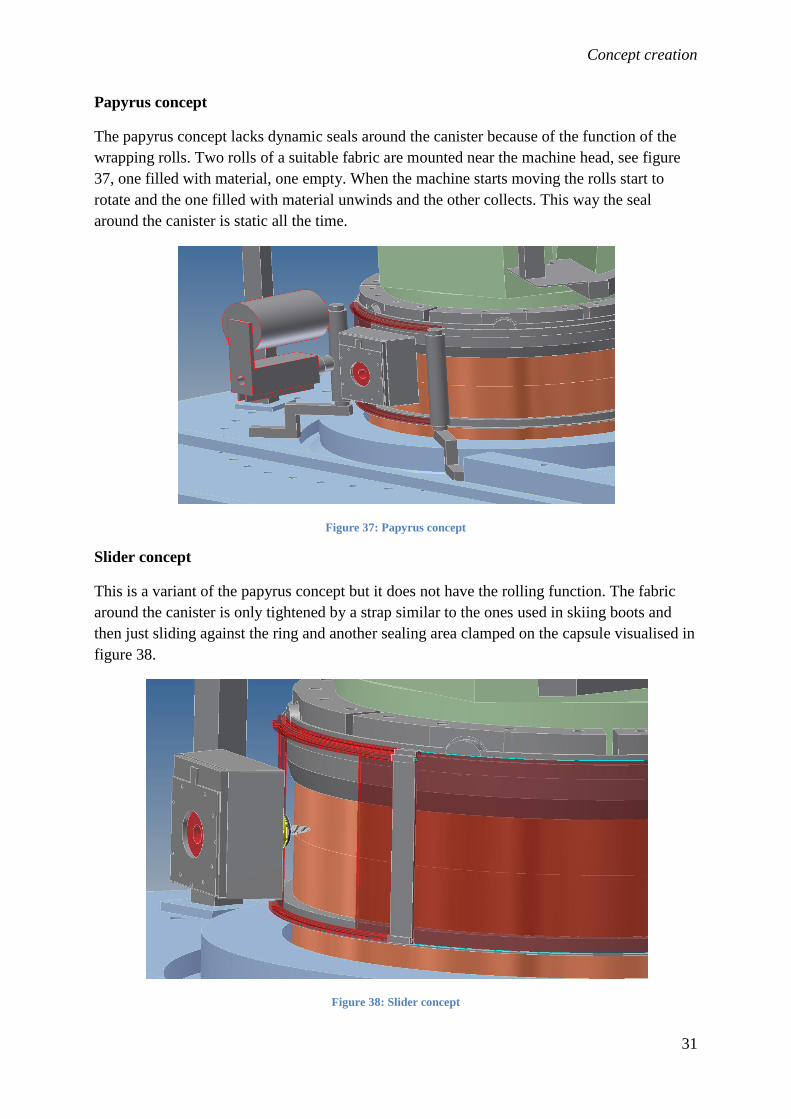
Papyrus concept
The papyrus concept lacks dynamic seals around the canister because of the function of the
wrapping rolls. Two rolls of a suitable fabric are mounted near the machine head, see figure
37, one filled with material, one empty. When the machine starts moving the rolls start to
rotate and the one filled with material unwinds and the other collects. This way the seal
around the canister is static all the time.
Figure 37: Papyrus concept
Slider concept
This is a variant of the papyrus concept but it does not have the rolling function. The fabric
around the canister is only tightened by a strap similar to the ones used in skiing boots and
then just sliding against the ring and another sealing area clamped on the capsule visualised in
figure 38.
Figure 38: Slider concept

Concept creation
32
Zipper concept
This concept lacks the dynamic sealing like the papyrus concept. Here an elastic fabric is
mounted on the ring and the other end on the canister or the machine base. This is divided in
the middle by a zipper with two zipper locks, one on each side of the machine head, one
opening the zipper and the second one closing the zipper, see figure 39. Zippers are available
in watertight versions and made to withstand at least 100°C [10].
Figure 39: Zipper concept with the zipper in the middle of the elastic fabrics. The zipper lock opener and closer is
located on the welding spindle.

Concept selection and detailed layout
33
7. Concept selection and detailed layout
7.1 Evaluation The ideas of how to solve the different problems listed above where joined together in
different concepts to be able to be evaluated easier. The evaluation were done by a pair wise
comparison method, see for example [11] and [12], to establish a fair evaluation between the
concepts. Briefly described, all the important demands that the shield should fulfil are listed.
These demands are then compared to each other with a question asked in this kind of manner,
“Is flexibility in the Z-direction more, less or as important as temperature resistance?” If the
flexibility is more important it gets the value 1, if the temperature is more important it gets the
value -1 and if they are equally important it gets the value 0. The scores are summarized of all
the demands and normalized to get a weighting in the range of 0 to 1. Then the concepts are
compared to each other with the same kind of thinking as before, a reference concept is
chosen that the rest of the concepts are compared to. If the concept compared is better than the
reference concept it gets a 1 on that property, if worse it gets a -1 and if equal it gets a 0. This
gives an overall ranking of the different concepts and the results can be analysed on what
differs the concepts from each other. The comparison was done by both the designer as well
as a person at the canister laboratory who is not involved in this project (Johan Holmgren) but
has good technical understanding. This was made to get a non objective view of the different
concepts. The comparison can be seen in appendix III.
The results from this comparison where rather equal between the two persons and the best
concept was the big bellow concept with the ring as upper sealing and the air pillow as the
lower sealing.
In Holmgren’s evaluation the papyrus concept got the same result as the big bellow concept
but the papyrus concept is rejected due to high complexity and non-standard components. It
would require much more development to get the papyrus rollers to function in the first place
and it would be much more unsecure than the big bellow concept due to the more complicated
technical solution.
7.2 Chosen concept The concept that convinced the most of all the available solutions and that was chosen for
further development is described in this chapter. A detailed description and deeper
explanation can be seen further down in this chapter.
The drilling unit will be removed to gain more space around the head, see figure 40. The
drilling will be performed by the welding spindle instead. Managing the drilling operation
with the welding spindle is fairly simple. In the welding spindle a tool fixing system from
Weldon is used [13]. Drills with Weldon mounts are available in the desired size from
different manufacturers, for example [14]. The welding spindle has today a maximum speed
of 600 rpm compared to the drilling modules 800rpm. But the drilling operation should work
with 600 rpm, calculations can be seen in appendix V. Some software changes are also
required to drill with the welding spindle but it is believed to be fairly simple.

Concept selection and detailed layout
34
Figure 40: Removal of drilling module
The space around the welding head is opened up with a big bellow allowing the spindle to
move in two directions. The below is mounted between a back plate which is mounted on the
welding spindle and a frame mounted on the S-direction cradle, see figure 41.
Figure 41: The sealing around the head. A back plate is fastened to the frame of the welding head (1). On the cradle
that only moves in the S-direction a frame (2) is mounted and between this and the head frame a bellow (3) is installed
that will allow the head to move in and out and up and down.
A sealing surface is placed high up where the cooling clamps are located today. This surface
is provided by a new solid cooling ring instead of the six separate cooling blocks existing
today. An air pillow seal between the machine base and canister is fitted that will inflate
when canister is in position, see air pillow description in chapter 6.2.
A lower sealing ring is mounted on the machine base to avoid exposing the seal as well as the
shield to high temperatures. This ring will be permanently mounted on the machine base, see
(4) in figure 41.
1
2
3
4

Concept selection and detailed layout
35
On both sides of the welding tool a hatch is placed, (1) in figure 42, to get easy access to the
welding head when changing tools etc. This hatch is strapped in place by brackets or screws
with sealing profiles around the edges. The transparent parts of the hatch can be made of some
sort of plastic. Having a transparent shield is preferable because the process can be easier
monitored visually.
Figure 42: The chosen concept for further development.
A flexible bellow that is gas tight and capable of withstanding temperatures up to 200°C and
higher is available from different companies [15]. Inflatable seals are available in many
different shapes and styles. Solutions exists that would fit this application and fulfill the
requirements stated [16]. Sealing ledges for the other parts in the shield are available in gas
tight versions and can handle the temperatures and other requirements stated [17].
Detailed description
Shield around the welding head
As mentioned earlier a bellow is installed to cope with the welding spindles movements in the
Z- and Y-direction. The larger end of the bellow is mounted on a frame connected to the large
part of the machine that only rotates and moves in the S-direction. This means a design with
less dynamic seals which eases possible sealing problems. The smaller end of the bellow is
mounted on to a plate around the head. This plate is an experiment board (bread board) [18],
see figure 43, with a lot of threaded holes for mounting of sensors, cameras and other
equipment. This board is stably mounted to prevent vibrations from the machine disturbing
1

Concept selection and detailed layout
36
the equipment mounted. This is done by brackets and mounting holes in each corner and
possibilities of adding mounting points in case of unwanted vibrations.
Figure 43: Head plate mounted on the welding spindle. Around the outer edges (black) the bellow is mounted. In the
picture two LVDT-sensors and the shield gas distributor around the spindle is mounted to the head plate.
The frame mounted on the machine has wide side pieces, (1) in figure 44, to be able to
contain sufficient sealing when welding is done off center in the S-direction. Here a maximal
offset of ±25mm is possible while keeping sealing intact.
Figure 44: Frame for the larger end of the bellow to mount on. Here the fixing clamps for the upper part of the head
shield are also to be seen. The fixing clamps need to be somewhat flexible to allow movements due to heat expansion.
Below the welding spindle a mounting and sealing plate is placed, see figure 45. This seals
the area between the frame and the lower sealing ring. The lower sealing plate also functions
1 1

Concept selection and detailed layout
37
as a mount and support for the side hatches. This plate will be stationary mounted and not
moved after the initial installation.
Figure 45: The lower head shield mounted on the machine
The two removable side hatches are placed on the lower sealing plate in machined groves.
The side hatches, see figure 46, are made of transparent polycarbonate plastic similar to the
plastic used in the existing shield. The polycarbonate plastic withstands temperatures up to
130°C [19] and the distance from the canister to the side shields are the same as in the
existing shield, thus the plastic should work in the new design as well. Plastic has a large
thermal expansion coefficient and this has to be compensated for when designing.
Calculations on what expansion levels are present in this application can be seen in appendix
VI.
Figure 46: The left side hatch.

Concept selection and detailed layout
38
The part above the welding spindle is sealed with the same kind of plate as the lower part but
removable. This plate is placed on top of the frame and the side hatches. It seals the area
between the frame and the sealing lip on the cooling ring of the machine. On the plate a
handle is mounted for easy handling when installing or removing the shield. The plate seen in
figure 47 is made of plastic for low weight and is held in place by the earlier mentioned fixing
clamps located on the frame.
Figure 47: The upper part of the head shield.
The three standing side brackets, seen in figure 48, are located with 90 degree separation
around the canister and support the four different plastic shields. They also provide an area for
the plastic in the side shields to expand in. When the plastic parts are placed in position the
covers, (1) in figure 48, are flipped down and tightened so that the seal around the edges of
the cover engages. Then the plastics can move while keeping the seal intact. In case the frame
design on the plastic shields does not work or if the plastic would not touch the sealing ledges
a strap can be tightened between the side brackets to hold the plastic against the seals.
Mounting points for these are integrated in the side brackets, (2) in figure 48.

Concept selection and detailed layout
39
Figure 48: Standing side brackets. In the side brackets the shield gas distribution pipes are also integrated which can
be seen in the figure. A magnification of the area (A) can be seen in figure 49.
Figure 49: Here the expansion allowance can be seen and the spring loaded shield clampers (1).
The upper part of the sealing around the canister is provided by a sealing lip mounted on the
cooling ring seen in figure 50. The cooling ring is made for different reasons. A solid ring is
simple to seal around instead of the existing six separate cooling clamps which have big
glitches between each other. The cooling ring helps to control the welding process as the
cooling clamps today are mounted in a bogie construction allowing movements in the copper
as described in chapter 4.9. If the of the lid is rough problems can occur with a solid ring
1 2
A
1

Concept selection and detailed layout
40
design that does not follow the surface. But the top of the lid is machined straight before
welding delivering a smooth surface. If the canister is placed obliquely in the machine the top
part of the machine can compensate for this as it is slightly floating on top of the three
hydraulic actuators seen in figure 9. The three actuators pull down the top part with the same
amount of pressure allowing it to tilt to some degree.
The cooling ring is designed thick enough not to flex when the probe heats up the material.
Calculations on what magnitude of forces the ring is exposed to are difficult and should be
considered before producing the ring. The cooling channels are designed the same way the
existing channels are designed to keep the cooling rate undisturbed. Channels are machined in
the bottom of the cooling ring, see (1) in figure 50 and then lids are welded on to the channels
to seal them.
Figure 50: Cooling ring with the cooling channels at (1) and the blocks for centring the canister at (2).
The bogie mounts are redesigned to apply pressure as evenly as possible to the top surface of
the cooling ring. The pressure is then transferred trough the cooling ring onto the top surface
of the lid equally. In figure 51 the redesigned bogie mounts can be seen.
Figure 51: Bogie mount which is bolted onto the top surface of the cooling ring.
On the machine base a sealing ring is bolted containing an inflatable air pillow to seal against
the canister and a sealing ledge on the outside to seal against the plastic shields. In figure 52
1
2

Concept selection and detailed layout
41
the lower sealing ring can be seen and in figure 53 a magnification of the air pressure channel
for the inflatable seal is shown.
Figure 52: Lower sealing ring bolted onto the machine base.
Figure 53: A cut trough of the lower sealing ring. Here the channel for the air hoses can be seen as well as the outer
sealing ledge.
To avoid damaging the inflatable seal the diameter of the seal when compressed is 50mm
larger than the canisters diameter. The hole in the machine base where the canister comes up
trough is 40mm larger in diameter than the canister leaving 5mm clearance radially to the air
pillow and sealing ring, seen in figure 54.
A

Concept selection and detailed layout
42
Figure 54: Clearance for the canister to avoid damages to the seals.
Sealing ledges will be used around many of the included parts and in most cases the ledges
will be compressed when working. The seal on the cooling ring however will have to be able
to seal a dynamic gap. A test showed that the upper part of the machine can move
approximately ±2mm off centre of the canister requiring the seal around the cooling ring to
either expand or compress.
Figure 55: Movement of the top part of the machine. When applying force as illustrated in the figure a movement of
around ±2mm off centre is registered of the whole top part.
The shield gas distribution is partially mentioned earlier and consists of four perforated tubes
distributed evenly around the circumference of the canister. The shielding gas will be argon
which is heavier than air thus it is preferable to fill argon from the bottom and up escaping the
5mm
2mm
F

Concept selection and detailed layout
43
air at the top part of the shield. Holes for mounting oxygen sensors and other equipment are
located on the side brackets and the top plate, see figure 55.
Figure 56: Placement for sensors and other equipment
Considerations on how to precise the centring of the canister in the machine has been done
and one solution could be the use of centring blocks fastened in the cooling ring, see (2) in
figure 50. These blocks will steer the canister in to the centre of the cooling block but not
centre it in the machine because the top part is still a bit floating.
Another possible solution for centring the canister could be the use of spring loaded wheels
mounted on the inside of the base of the machine in order to steer the canister into the middle.
When raising the canister trough the hole in the machine base the wheels will force it into the
middle of the hole, see figure 56. When welding is finished and canister is lowered down the
wheels should be able to move because welding flash can occur and stick out radially from
the canister. The wheels should be able to suspend the flash and avoid damaging the surface
of the canister.

Concept selection and detailed layout
44
Figure 57: Alternative method of centring the canister.
7.3 Lifting the lid With the current design the lid can be lifted 20-25mm with the seal kept intact. The highest
and lowest position of the lid can be seen in figure 57. This way possible air trapped in the
joint between the lid and tube can be escaped. But as mentioned earlier the complete internal
air escape cannot be done with the current design of the machine and lid.
Figure 58: On the right, lid pressed on to the tube, on the left, lid lifted

FMEA
45
8. Failure Modes and Effect Analysis (FMEA) In order to prevent and minimize the risk for failures or other malfunction an FME analysis
where done. The analysis is performed by the method described in [20]. This lists possible
problems and risks in the design and actions on how to prevent these from happening. The
worst modes for failure where dirt and other objects trapped in seals causing air to leak into
the gas shield. This could also damage the different seals so that replacement is needed. A
swarf shield for hot drilling chips should be considered to prevent damaging the seals. The
shield could be a simple thin sheet metal cover that is placed in the near surrounding below
the spindle when operating the drill.
Small holes and gaps in the interfaces between components will exist but inside the gas shield
a small overpressure will be present keeping air from getting in. These holes and gaps should
off course be kept at a minimum. Another mode that could occur is moving the machine in the
S-axis when having the side hatches mounted. If the movement is too large the bellow frame
will hit the side hatches and damage them. Solution for this is mounting a safety switch which
is activated when the side shields are in place and software warnings to remind operators. The
FME analysis can be seen in appendix VII.

Reflexions and further work with the design
46
9. Reflexions and further work with the design The design of the gas shield is believed to fulfil the requirements stated in the beginning of
the work well. It is of course difficult to visualise and ideate the behaviour of some of the
components but simple practical experiments could show either it would work or not. Some of
the components cannot be tested before manufacturing but they can be designed with different
solutions for the same problem. It is cheaper to build in several solutions in the first design
than to install everything and then perceive that it did not work out the way planned and
redesign the product. It is also believed that the design will ease keeping the conditions
consistent when doing experiments with welding. To be able to perform adequate experiments
and compare those to each other the surrounding conditions should be kept as similar as
possible from one experiment to another. This managed, for example, by the solid cooling
ring applying pressure evenly to the lid, increased mounting possibilities for sensors, cameras
and other equipment on the experiment board and a gas shield delivering an almost oxygen
free atmosphere around the weld.
The work with the final design should continue with testing of the different components. Test
if the plastic side shields can be held in place with the frame design or are the straps needed,
as mentioned in chapter 7.2. Also, testing should be done to determine what sealing ledges to
use, different alternatives exist and simple tests could show which one suits best. Then a
general thought on how to design the components for assembly and manufacturing, some of
this is already done but could be revised one more time. A FEM-analysis or similar simulation
on what magnitude of forces and expansion the cooling ring has to endure would also be
suitable.

Reference list
47
10. Reference list [1] SKB, 2006. Kapsel för använt kärnbränsle, Svetsning och tillverkning vid förslutning.
SKB R-06-04. Svensk kärnbränslehantering AB. Available at:
http://www.skb.se/upload/publications/pdf/R-06-04.pdf (2014-03-14)
[2] ESAB, n.d. Available at: http://www.esab.se/se/se/support/upload/tigsvetsning.pdf
(2014-03-14)
[3] Savolainen K, 2012. Friction stir welding of copper and microstructure and properties of
the welds. Doctoral thesis. Aalto University, Finland. Available at:
http://lib.tkk.fi/Diss/2012/isbn9789526045009/isbn9789526045009.pdf (2014-03-14)
[4] SKB, 2013. Kostnader från och med år 2015 för kärnkraftens radioaktiva restprodukter.
SKB 1420189, Svensk kärnbränslehantering AB. Available at:
http://www.skb.se/upload/publications/pdf/Plan_2013.pdf (2014-03-14)
[5] Björk M, Elger R, 2013. Oxidation kinetics of copper at reduced oxygen partial pressures,
SKB 1410172. Svensk kärnbränslehantering AB.
[6] Huntingdon fusion, n.d. Available at: http://huntingdonfusion.com/en/products/weld-
purge-accessories/weld-trailing-shields.html (2014-03-14)
[7] Björck M, 2013. Evaluation of existing gas shield setup of the friction stir weld machine
at the canister laboratory, SKB 1379358. Svensk kärnbränslehantering AB.
[8] Björk M, 2013. FSWL94- Measurement of temperatures and surrounding oxygen levels
during welding. SKB 1371191. Svensk kärnbränslehantering AB
[9] Biltema AB, n.d. Available at: http://www.biltema.se/sv/Bil---MC/Lasta-och-
Dra/Slap/Tillbehor/Flaklas-41231/ (2014-05-05)
[10] Titex Vertriebs-GmbH n.d. Available at:
http://www.tizip.com/index.php?lang=en&http:/ (2014-05-20)
[11] Krus P, 2012. Design Analysis and Synthesis. Liu
[12] Cross N, 2000. Engineering design methods, strategies for product development, Third
edition. The open university, Milton Keynes, UK. John Wiley and sons, LTD.
[13] Weldon Tool Company, n.d. Available at: http://www.weldontool.com/ (2014-05-06)
[14] Euroboor, n.d. Available at: http://www.euroboor.info/drilling/other-drills/twist-
drills/weldon-shank (2014-05-06)
[15] Protite AB, n.d. Available at:
http://www.protite.se/index.php?option=com_content&view=article&id=3&Itemid=129
(2014-05-16)

Reference list
48
[16] Dynamic rubber, Inc. n.d. Available at:
http://www.dynamicrubber.com/inflatable_seals/index.html (2014-05-16)
[17] Kuntze & Co AB, n.d. Available at: http://www.kuntze.se/produkter/gummilister-
borstlister/ (2014-05-16)
[18] Thorlabs, n.d. Available at:
http://www.thorlabs.de/newgrouppage9.cfm?objectgroup_id=159 (2014-05-07)
[19] Christian Berner AB, n.d. Available at: http://www.christianberner.se/$-
1/file/polykarbonat-pc.pdf (2014-05-07)
[20] Dieter G, Schmidt L, 2009. Engineering design, Fourth edition. The university of
Maryland, New York, NY, McGraw-Hill
[21] Wedevåg Tools AB, n.d. Available at: http://wts.wedevag.se/Drills.aspx (2014-05-19)
[22] Alfatool international AB, n.d. Available at:
http://www.alfatool.se/Resources/ResourceBank/pdflogin/Teknikh%C3%A4fte%20Borr.pdf
(2014-05-19)
[23] Engineering Toolbox, n.d. Available at: http://www.engineeringtoolbox.com/linear-
expansion-coefficients-d_95.html (2014-05-20)

Appendix
49
9. Appendix
Appendix I - Gantt chart
Mont January February March April May June Week w.4 w.5 w.6 w.7 w.8 w.9 w.10 w.11 w.12 w.13 w.14 w.15 w.16 w.17 w.18 w.19 w.20 w.21 w.22 w.23 w.24 w.25 w.26 Activity Planing report Literature study Probem formulation Check/complement Cad-model Planing report (dead line) Half time report Information collection
Concept generation Half-time report (dead line) Presentation of concepts for concerned parties Final report Concept generation Concept evaluation Detailed layout Preliminary final report Thesis presentation Final report

Appendix
50
Appendix II - Function-Method-tree
The different concepts and ideas on how to solve the big problems when designing a new gas shield are listed in the FM-tree. The flexibility
column contains solutions on how to allow the machine to move in the directions stated. The mounting position column contains positions on
where the shield could be mounted in the machine. The sealing column contains solutions on how to manage the sealing of different parts in the
shield to keep air of getting into the welding zone. And the place of dynamic sealing contains places on where the sealing probably has to be able
to move and still provide sealing.

Appendix
51
Appendix III – Concept evaluation
Pair wise comparison method
The comparison here done by a technical person that isn’t involved in the project.
Here the demands and properties are compared to each other.
Then they are ranked after the respective points and the results weighted with a value between
0 and 1.

Appendix
52
Then the concepts are compared to a reference concept and the results are calculated in the
end. A normalized result between -1 and 1 is also presented.
The concepts described in the concept creation chapter are put together to complete solutions
for the gas shield around the whole canister. There are of course many more combinations of
these concepts but the combinations selected represent all the different concepts in some way.
Complete
concept
Head sealing Upper sealing Lower sealing Shield around
canister
1(big bellow) Big bellow Solid cooling
ring
Air pillow
seal, sealing
ring on
machine base
Slider
2(sandblast Sandblast The ring Clamped on
canister
Shields fixed
to machine
base
3(papyrus) Bellow The ring Clamped on
canister
Papyrus
4(zipper) Zipper The ring Clamped on
canister
Zipper
5(bellow) Bellow The ring Clamped on
canister
Shields fixed
to machine
base

Appendix
53
The same evaluation done by the designer.

Appendix
54
Appendix IV - Concepts for the machine in INKA
Filling the whole cell with gas concept
An early solution of the problem was to fill the whole welding cell with shielding gas. The
space that would have been required to be filled with gas is approximated from drawings of
the planned welding cell. This box is around 8 x 8 x 7 meter so in total around 448m3.
Additionally a space below the floor around the canister would have to be filled with gas. This
space is approximately 1.5^2*pi/4*4.5 = 8m3.
This total space of around 456m3 would first have to be flushed with gas once or twice to get
rid of all air inside the cell. This would require approximately 912m3 of gas for each weld and
considering a constant flow of gas into the cell due to leakage this would require an addition
of 1 m3 of gas. This is calculated from a gas flow into the cell of 20 lit/min and the welding
time are approximated to 50 min.
A 50litre tube of argon shield gas at 200 bars is 10m3 in atmospheric pressure, so that would
require 45 tubes of argon. To fill one tube with argon costs around 2000SEK, in total for 45
tubes = 90000SEK.
And summarizing the gas for the welds performed in the robotic cell which is 6200. It all
comes down to a cost of around 558milj SEK. This concept is rejected due to high costs and
other difficulties in the design.

Appendix
55
Tent concept (Maskintekniks idea)
This concept involves a tent that is put over the whole machine. Then air is sucked out from
the inside of the tent compressing the volume in the tent to a minimum. Inert gas is the
applied to the inside of the tent. This concept would consume a lot less gas than filling the
whole cell. The gas could be reused if a kind of airlock is used to seal against the canister in
two stages, see figure 30.

Appendix
56
Appendix V - Drilling speed calculations for copper Considering a high speed steel (HSS) drill the cutting speed for copper is around 20-35[23]
m/min. Spindle speed can be calculated with [24]:
Where:
n = Spindle speed
Vc = Cutting speed
d = Diameter of drill
This with a 15mm drill results in a spindle speed of 600-800 rpm.
If using a carbide (HM) drill, cutting speed for copper is 100-125 m/min and results in a
spindle speed around 2000rpm.
Appendix VI - Thermal expansion of polycarbonate The thermal expansion coefficient for polycarbonate is 65*10^-6 /K [24].
The shields used in the new design are around 900mm long and 500mm high.
If the temperature is raised from 20 to 100°C the expansion in length will be:

Appendix
57
Appendix VII – FME analysis
Com
pon
ent
Failure mode Effects of failure Sev
erity
Causes of failure Occu
rrence
Corrective action Detectio
n
ratin
g
RP
N
Bellow Bellow breaks Air leak into gas shield, bellow defect 6 Foreign part causing bellow to rip
apart
2 Check that no foreign parts can hit the
bellow 2 24
6 Hot drilling swarf hitting bellow and
melting the fabric
6 Check that the swarf shield is in the right
place 4 144
6 Tools placed on bellow and/or
forgotten there when operating
4 Check that no tools are placed or left on
the bellow, clean before operating 2 48
Experime
nt board
Threaded holes on board
faulty
Components cannot be mounted on board 4 Screws mounted wrong 4 Mount screws properly 1 16
Board vibrates/loose Measuring equipment reads incorrect values 6 Board mounting screws loose or too
few mounting points of board
3 Tighten mounting screws and/or install
more mounting points 4 72
Side
shields
Side shields break Air leak into gas shield, side shields defect 9 Machine moved too much in the S-
direction causing the bellow frame
hitting the side shield
1 No S-direction movement with side
shields installed 1 9
Seals on side shield defect Air leak into gas shield 6 Hot drilling swarf hitting seals
causing them to melt, other dirt
trapped in seals causing improper
sealing
6 Check that swarf shield is in right place,
clean seals and sealing areas before
installation
3 108
Inflatable
seal
Inflatable seal not sealing
properly
Air leak into gas shield
6 Hot drilling swarf melting inflatable
rubber seal, dirt trapped between
canister and seal
6 Check that swarf shield is in right place ,
clean inflatable seal before expanding
4 144
6 To low pressure in inflatable seal
4 Check pressure in inflatable seal
3 72
Inflatable seal damaged Air leak into gas shield
6 Canister hitting the inflatable seal
when raising or lowering the
canister
6 Check that no excessive parts stick out
from the surface of canister, check that
inflated seal is completely compressed
3 108
Other
side
shields
and
standing
brackets
Side shields not sealing
properly
Air leak into gas shield
6 Shields not mounted correctly, dirt
in sealing areas
5 Check mounting of shield, clean sealing
areas
4 120

Appendix
58
Cooling
ring
Components around
canister not sealing
properly
Air leak into gas shield 6 Canister not centred in the machine
causing the seal on the cooling ring
not to seal against the surfaces
defined
4 Mount canister in centre of the machine 2 48
Top plate not sealing
correctly
Air leak into gas shield 6 Canister mounted either too low or
too high in the machine causing the
sealing lip on the cooling ring to not
seal against the top plate
3 Mount canister so that the sealing lip on
the cooling ring aligns the centre of the
thickness of the top plate
2 36
1
2
3
4
5
6
7
8
9
10
Severity: 1-10 The effect is not noticed by the customer
Very slight effect noticed by customer; does not annoy or inconvenience customer
Slight effect that causes customers annoyance, but they do not seek service
Slight effect, customer may return product for service
Moderate effect, customer requires immediate service
Significant effect, causes customer dissatisfaction; may violate a regulation or design code.
Major effect, system may not be operable; elicits customer complaint; may cause injury
Extreme effect, system is inoperable and a safety problem. May cause severe injury.
Critical effect, complete system shutdown; safety risk
Hazardous; failure occurs without warning; life-threatening
1
2
3
4
5
6
7
8
9
10
Occurrence: 1-10 Extremely remote
Remote, very unlikely
Very slight chance of occurrence
Slight chance of occurrence
Occasional occurrence
Moderate occurrence
Frequent occurrence
High occurrence
Very high occurrence
Extremely high occurrence
1
2
3
4
5
6
7
8
9
10
Detection rating: 1-10 Almost certain to detect
Very high chance of detection
High chance of detection
Moderately high chance of detection
Medium chance of detection
Low chance of detection
Slight chance of detection
Remote chance of detection
Very remote chance of detection
No chance of detection; no inspection
Note: The severity, occurrence and detection rating are assessed from the designers’ point of view. The risk priority number (RPN) is calculated
by multiplying the numbers in the three categories to get a concrete comparison between the modes.