Design and Development of a Micropitting Test Rig905851/FULLTEXT01.pdf · with design modifications...
64
Design and Development of a Micropitting Test Rig FENG GAO Master of Science Thesis Stockholm, Sweden 2015
Transcript of Design and Development of a Micropitting Test Rig905851/FULLTEXT01.pdf · with design modifications...

Design and Development of a Micropitting Test Rig
FENG GAO
Master of Science Thesis
Stockholm, Sweden 2015


Design and Development of a Micropitting Test Rig
Feng Gao
Master of Science Thesis MMK 2015:115 MKN
143 KTH Industrial Engineering and
Management Machine Design
SE-100 44 STOCKHOLM


1
Examensarbete MMK 2015:113 MKN
143
Konstruktion och utveckling av en ytutmattningsrigg
Feng Gao
Godkänt
2015-11-26
Examinator
Ulf Sellgren
Handledare
Sergei Glavatskih
Uppdragsgivare
KTH Machine Design Dept.
Kontaktperson
Sergei Glavatskih
Sammanfattning En av de vanligaste typ av fel i rullande kontaktmekanik, såsom i kugghjul och kullager, är
mikropitting. Fenomenet har nämligen blivit ett stort problem och betraktas som en tidig
indikator för utmattning samt kan leda till tidiga utmattningsbrott I kugghjul och kullager. Detta
utvecklingsarbete krävs en mångsidig testrigg som kan återskapa gropfrätning och mikropitting
under kontrollerade förhållande I laboratorium.
Denna examensarbete har genomförts inom Avdelningen för Maskinteknik vid Kungliga
Tekniska Högskola (KTH). Arbetet utgör en vidareutveckling på ett projekt för kursen
”Maskinkonstruktion högre kurs” inom maskindesignprogrammet. Utöver en analys av
utmanningarna, det nuvarande arbetet presenterar designförändringar och vidareutveckling från
det tidigare testriggen. Alla problem som påträffades har kunnat lösas. Till slut uppvisar den
nymonterade testriggen alla förväntade egenskaper, nämligen stabilitet, förbättrad tysthet samt
god performans. Den föreslagna metoden utgör därmed ett kostnadseffektivt sätt att utveckla
testrigg för mikropitting.
Arbetet består, utöver det fysiska produkten, av lösningar, rekommendationer och relevanta
dokument såsom monteringsschema och programkod. En utförlig diskussion av tankar och
erfarenheter från projektet presenteras. Baserat på dessa kan det nämnda arbetet genomföras och
höjas till en advancerad nivå.
Nyckelord: mikropitting, provnngsrigg, konstruktion, utveckling

2

3
Master of Science Thesis MMK 2015:113 MKN
143
Design and Development of
a Micropitting Test Rig
Feng Gao
Approved
2015-11-26
Examiner
Ulf Sellgren
Supervisor
Sergei Glavatskih
Commissioner
KTH Machine Design Dept.
Contact person
Sergei Glavatskih
Abstract One of the common failure modes in rolling contacts, such as in gears and rolling element
bearings, is micropitting which has become a big issue. It is considered as a fatigue indicator and
can lead to premature gear and bearing failure. This development work requires availability of a
versatile test rig which reproduces the pitting or micropitting phenomenon under controlled
conditions in the laboratory.
The thesis has been carried out in the Department of Machine Design at KTH Royal Institute of
Technology. It is a continuation of the project in the Advanced Machine Design course or
Maskinkonstruktion högre kurs HK (in Swedish) as part of the Machine Design master
programme at KTH. After specifying the scope and analyzing the challenges, this work deals
with design modifications and further development of the previous test rig. All the problems
addressed at the beginning have been solved. At the end, the newly assembled test rig indicates a
stable, quieter and well performed working status as intended. The thesis work turns out a cost-
effective way of developing micro-pitting test rig.
Apart from physical deliverables; feasible solutions, recommendations and relevant documents
such as specifications, program codes are provided in this paper. Some experience and thoughts
during the project are also discussed in detail. Based on these, the mentioned future work can be
performed and promoted to an advanced level.
Keywords: micropitting, test rig, design, development

4

5
FOREWORD
I would like to thank my thesis supervisor Professor Sergei Glavatskih who entrusted me this
task for his continuous guidance during the whole project; also for his high spirit, enthusiasm
and commitment to excellence.
I am particularly grateful to Dr. Stefan Björklund and PHD candidate Mario Sosa from KTH
Machine Design for their participation in the group discussion. Their invaluable advice and
comments are always inspiring and help very much.
I wish to express my sincere gratitude towards Dr. Ulf Sellgren at KTH for giving his attention
to this project, as well as encouraging me to approach the destination.
Special thanks to Tomas Österberg and Peter Carlsson for their assistance with manufacturing
and parts purchasing. They all possess admirable engineering expertise. I am also thankful for
their kind help during the daily work.
I am indebted to my family members and my best friends for their constant support. Without
their love and tolerance, I could not go any further during my studies at KTH. Thank you all!
Feng Gao
Stockholm, November 2015

6

7
NOMENCLATURE
Notations
Symbol Description
E Young s modulus (Pa)
r Radius (m)
t Thickness (m)
ν Poisson’s ratio
pm Mean contact pressure (Pa)
pmax Maximum contact pressure (Pa)
R’
Effective contact radius (m)
E’ Effective modulus of elasticity (Pa)
η0 Lubricant the viscosity (Pa·s)
α Pressure-viscosity coefficient (GPa-1
)
U Surface velocity (m/s)
P Load (N)
L Contact length (m)
δ Interference between the hub and shaft (m)
di Inner diameter of the hole in shaft (m)
dy Outer diameter of the hole in shaft (m)
Di inner diameter of the hub (m)
Dy Outer diameter of the hub (m)
σ Tensile stress (Pa)
f Spring deflection (m)
r0 Minor radius of the disk spring(m)
T Friction torque (Nm)
Ff Frictional force (N)
µ Kinetic frictional coefficient
d Diameter of the central ring (m)
N Normal force (N)
Fr Rolling resistance force (N)
Crr Coefficient of rolling friction

8
Abbreviations
CAD Computer Aided Design
CAE Computer Aided Engineering
SE Solid Edge
FZG Forschungsstelle für Zahnräder und Getriebebau (Gear Research Centre)
MPR Micro-pitting Rig
WAM Wedeven Associates Machines
SRR Slide to Roll Ratio
AC Alternative current
HK Maskinkonstruktion högre kurs (Advanced Machine Design course)

9
TABLE OF CONTENTS
SAMMANFATTNING ............................................................................................. 1
ABSTRACT .............................................................................................................. 3
FOREWORD ............................................................................................................. 5
NOMENCLATURE .................................................................................................. 7
TABLE OF CONTENTS .......................................................................................... 9
1 INTRODUCTION ........................................................................................... 11
1.1 Background ............................................................................................... 11
1.2 Purpose ...................................................................................................... 11
1.3 Scope ......................................................................................................... 11
1.4 Delimitations ............................................................................................. 12
1.5 Methods ..................................................................................................... 12
2 FRAME OF REFERENCE ............................................................................. 13
2.1 Pitting and Micropitting ............................................................................ 13
2.2 Micropitting tests ...................................................................................... 14
2.3 Hertzian line contact ................................................................................. 18
2.3 EHL-line contact and SRR ........................................................................ 19
2.4 Interference fits and disc spring compression ........................................... 20
2.5 Shaft alignment basics............................................................................... 21
3 PREVIOUS WORK ........................................................................................ 23
3.1 Test rig configuration ................................................................................ 23
3.1 Challenges after first test run .................................................................... 26

10
4 MODIFICATION AND DEVELOPMENT ................................................... 28
4.1 Lower motor adjustment ........................................................................... 28
4.2 Belt tensioner subassembly ....................................................................... 29
4.3 Shafts and bearings locating ..................................................................... 30
4.4 Loading mechanism improvement ............................................................ 31
4.5 Large ring fastening ................................................................................. 32
4.6 Central ring mounting .............................................................................. 36
4.7 Torque transducer support........................................................................ 37
4.8 Shaft alignment solution .......................................................................... 39
4.9 Housing design development ................................................................... 44
4.10 Sealing arrangement ............................................................................... 45
5 RESULTS ........................................................................................................ 48
6 DISCUSSION AND CONCLUSIONS ........................................................ 499
6.1 Discussion ................................................................................................. 49
6.2 Conclusions ............................................................................................... 50
7 RECOMMENDATIONS AND FUTURE WORK......................................... 51
7.1 Recommendations ..................................................................................... 51
7.2 Future work ............................................................................................... 51
8 REFERENCES ................................................................................................ 52
APPENDIX A: PROJECT TIME PLAN ................................................................ 54
APPENDIX B: REQUIREMENT SPECIFICATIONS .......................................... 55
APPENDIX C: MATLAB PROGRAM CODE ...................................................... 56
APPENDIX D: LIST OF FIGURES ....................................................................... 59

11
1 INTRODUCTION
This chapter describes the background, the purpose and scope, the limitations and the methods
used in the presented project.
1.1 Background
This work has been performed as a master thesis project in the Department of Machine Design at
KTH Royal Institute of Technology. It is a continuation of the project in the Advanced Machine
Design course or Maskinkonstruktion högre kurs HK (in Swedish) which is also a required
curriculum of the Machine Design master programme at KTH.
The early work from the HK course concluded in January 2015. During the previous project; the
design concept was made, the key components were finally delivered, the main structure were
assembled and able to start the test run. Due to the timeframe limitation, the machine was not
perfectly functioning. Some technical issues were detected when running. More detailed design
and modification work were definitely needed. It was decided that this project should be further
developed as a master thesis at the end of the HK course.
A tremendous amount of research has been going on in the field of fatigue and wear (Laine, et al.,
2008). One of the common failure modes in rolling contacts, such as in gears and rolling element
bearings, is micropitting. This master project is to develop a laboratory test rig which is of the
interest to the research on micropitting or pitting.
1.2 Purpose
The final purpose of the developing this Micro-pitting test rig is to deliver a feasible solution to
carry out the laboratory test which can reproduce the phenomenon under controlled conditions
such as contact pressure, slide/roll ratio, lubricant, test materials, etc. Besides, all the necessary
data are supposed to be collected including fiction torque, loading force, temperature and so on.
1.3 Scope
This thesis project deals with design modifications and development of the micropitting test rig.
The main scope of this work covers the following topics:
Shafts Alignment to guarantee the line contact between specimen surfaces.
User-friendly fastening and replacing manner for all the test rings.
Bearings arrangement and shaft positioning.
Loading mechanism improvement.
Belt locating adjustment.
Housing changes and sealing solutions.
Modification and designing for relevant parts and subassemblies.
Manufacturing, purchasing, assembling and test runs.

12
1.4 Delimitations
The target of this project is to make the test machine functioning accurately as intended. The
thesis was carried on based on the old work from HK course. From product development
perspective, this work focused on the detailed design phase. However, some delimitations of this
work are defined as follows,
The relevant sensors are not selected and purchased.
Data acquisition and software interface design are not executed.
Computer controlled circuit design is not included.
Signal processing and analysing is not involved in this stage.
1.5 Methods
Some practical methods are conducted to tackle the technical challenges. As the main scope
stated above, problems are basically decomposed into sub-tasks, where the requirements and
questions are also defined.
The modelling work is implemented in CAD software Solid Edge (SE) ST7 which is officially
used in KTH. In the following chapter, all the relevant 3d model, explosion view, 2D drawing
etc. are generated from SE.
Theoretical calculation is done to figure out the load according to Hertzian contact theory.
Available online calculators are also used and compared.
MATLAB is employed to make the model based design and the design optimization.
Milling, turning and grinding etc. are commonly adopted in terms of manufacturing. Using the
standards parts is always an efficient and error proof way.
Apart from those technical means, project meeting on a weekly basis is also the essential strategy
to make sure the project keeps moving forward in the right direction. Together with supervisor,
the work in every stage can be addressed and evaluated by each discussion. The project time plan
is enclosed in the Appendix.

13
2 FRAME OF REFERENCE
This chapter presents the reference frame that is necessary for the performed testing machine
design and development.
2.1 Pitting and Micropitting
Pitting is the surface fatigue failure, it happens only after a large number of contact cycles (Beek,
2009). A particle of material breaks away from the sliding surface (often with rolling bearings,
roller guides, cans and gears). It results from the repition of the surface or subsurface (often
occurs when heavily loaded, lubricated surfaces) stress cycles which are beyond the endurance
limit of the material. Pits are typically in the order of 1000 μm (Beek, 2009).
Micropitting is a microscopic form of rolling contact fatigue and wear, which is most often
found in ground, hard steel surfaces such as those in casehardened gears. It is normally
associated with concentrated rolling-sliding contacts under conditions where the lubricant film is
rather thin compared to the height of the surface roughness. Pits are typically less than 100
microns wide. See Figure 1 (Baker, 2008).
Figure 1 Microphotograph of pitting (left) and micropitting (right)
The difference between pitting and micropitting is the size of the pits after surface fatigue. Pits
formed by micropitting have the characteristic dimension of around 10 μm. Generally,
micropitted metal often has a frosted or gray appearance. Normal pitting creates larger and more
visible pits. See Figure 2 (ATSB, 2000), (Kotzalash & Doll, 2010).
Figure 2 Pitting on gear teeth (left) and Micropitting on bearing inner raceway (right)

14
2.2 Micropitting tests
Micropitting is known to be influenced by operating conditions such as temperature, load, rolling
and sliding speeds, specific lubricant film thickness, lubricant additives, viscosity grade and
surface material properties (Martins, et al., 2011). Micropitting test is of great importance to the
research on micropitting. Engineers and researchers have concentrated on the development of
test rigs and test procedures in order to reproduce micropitting phenomenon under controlled
conditions. Generally, these tests provided a better understanding on micropitting behavior and
enabled the identification of those parameters which control the problem. The micropitting tests
have commonly carried out on gear test rigs or on disc machines. Disc machines have been
widely used and have proved to be a controlled way to produce micropitting under controlled
conditions (Laine, et al., 2008). Examples of the use of various machines are showcased in this
section.
2.1.1 FZG Gear test
The FZG gear test rig is a test machine with power circuit. The drive gearbox and the test
gearbox are frictionally engaged by two torque shafts (hereinafter only mentioned as shafts). For
load application a clutch is provided on shaft 1. The temperature in the test gearbox can be set
and controlled. The test rig is driven by an electric motor. The speed is 1500 rpm. The variable-
speed test rig allows speeds from 100 rpm to 3000 rpm and two directions of rotation. The load
can either be applied by a weight system or with the tension ratchet or with an automatic load
system. See Figure 3 (Strama-MPS, 2015) and Figure 4 (University of Leoben, 2015). One main
issue of FZG rig is that the test is a complicated, expensive and time-consuming process
(Stadtfeld, 1996). Accelerated approach, for example compromising with the testing material
properties, can be used to result in a relatively short time span (Amarnath, et al., 2009). However,
it deviates from the real test situation.
Figure 3 FZG gear test rig
15
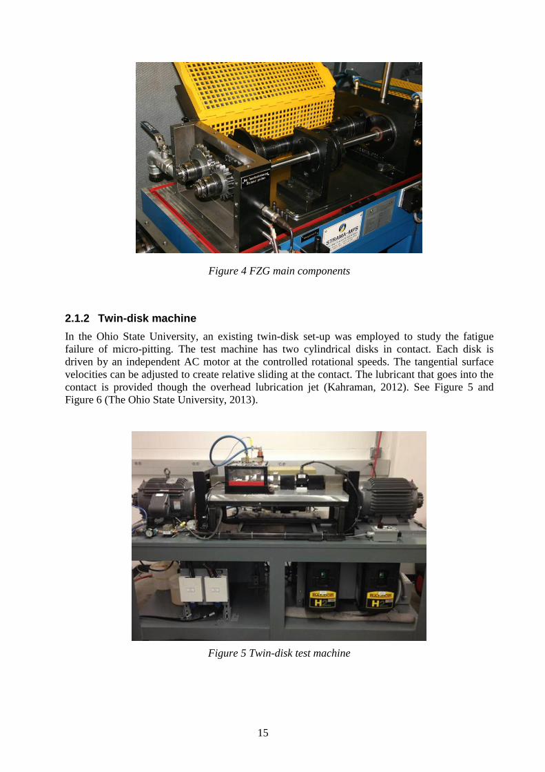
Figure 4 FZG main components
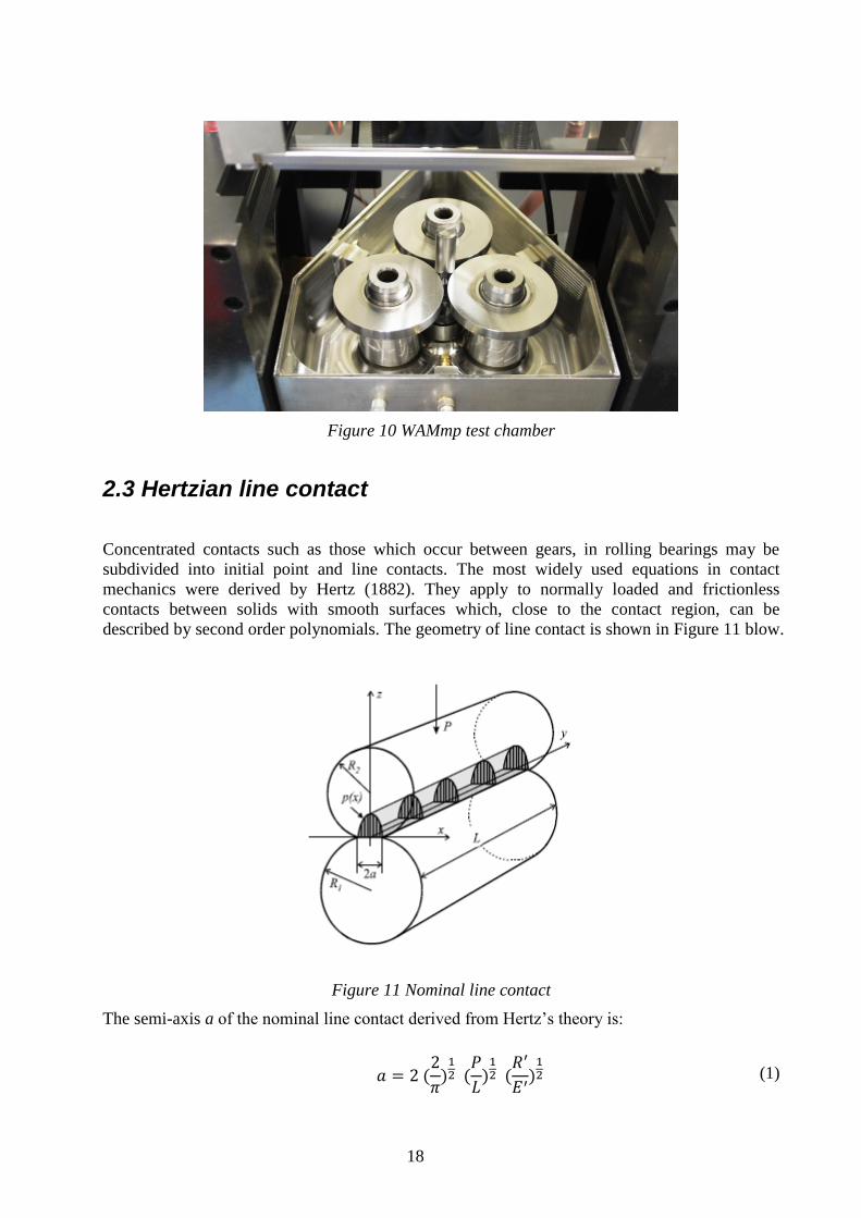
2.1.2 Twin-disk machine
In the Ohio State University, an existing twin-disk set-up was employed to study the fatigue
failure of micro-pitting. The test machine has two cylindrical disks in contact. Each disk is
driven by an independent AC motor at the controlled rotational speeds. The tangential surface
velocities can be adjusted to create relative sliding at the contact. The lubricant that goes into the
contact is provided though the overhead lubrication jet (Kahraman, 2012). See Figure 5 and
Figure 6 (The Ohio State University, 2013).
Figure 5 Twin-disk test machine

16
Figure 6 Close-up view of the set-up
2.1.3 Three-contact disc MPR
The MPR is a computer controlled three-contact disc instrument in which there are three
‘counterface’ rings of equal diameter positioned apart with a smaller diameter roller located in
the middle and in contact with all the rings. This arrangement allows the test roller to be
subjected to a large number of rolling contact cycles in a short period of time and hence
significantly reduces testing time (Wang, et al., 2013). At a typical entrainment speed of 3.5m/s,
the central test roller will experience approximately one million contact cycles per hour. See
Figure 7and Figure 8 (Baker, 2008)
Figure 7 MPR schematic

17
Figure 8 MPR three ‘counterface’ rings
2.1.4 WAM micropitting machine
WAMmp utilizes an advanced gearbox design and other support components to precisely control
speeds of test components while measuring incipient sliding conditions on test articles under an
applied load. It is intended to evaluate oil and material pairs for specific performance
characteristics related to high cycle fatigue and micropitting. See Figure 9 and Figure 10
(Wedeven Associates, Inc, 2015). These test conditions are designed to represent the lubricated
coatings found on the integral raceways of planetary gears. Rolling elements made from
materials like M50 operate against case carburized gear steels under near pure-rolling conditions.
Figure 9 WAMmp - Micropitting machine
18
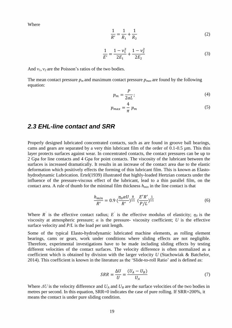
Figure 10 WAMmp test chamber
2.3 Hertzian line contact
Concentrated contacts such as those which occur between gears, in rolling bearings may be
subdivided into initial point and line contacts. The most widely used equations in contact
mechanics were derived by Hertz (1882). They apply to normally loaded and frictionless
contacts between solids with smooth surfaces which, close to the contact region, can be
described by second order polynomials. The geometry of line contact is shown in Figure 11 blow.
Figure 11 Nominal line contact
The semi-axis a of the nominal line contact derived from Hertz’s theory is:
𝑎 = 2 (2
𝜋)
12 (
𝑃
𝐿)
12 (
𝑅′
𝐸′)
12 (1)
19
Where
1
𝑅′=
1
𝑅1+
1
𝑅2 (2)
1
𝐸′=
1 − 𝜈12
2𝐸1+
1 − 𝜈22
2𝐸2 (3)
And ν1, ν2 are the Poisson’s ratios of the two bodies.
The mean contact pressure pm and maximum contact pressure pmax are found by the following
equation:
𝑝𝑚 =𝑃
2𝑎𝐿; (4)
𝑝𝑚𝑎𝑥 =4
𝜋 𝑝𝑚 (5)
2.3 EHL-line contact and SRR
Properly designed lubricated concentrated contacts, such as are found in groove ball bearings,
cams and gears are separated by a very thin lubricant film of the order of 0.1-0.5 µm. This thin
layer protects surfaces against wear. In concentrated contacts, the contact pressures can be up to
2 Gpa for line contacts and 4 Gpa for point contacts. The viscosity of the lubricant between the
surfaces is increased dramatically. It results in an increase of the contact area due to the elastic
deformation which positively effects the forming of thin lubricant film. This is known as Elasto-
hydrodynamic Lubrication. Ertel(1939) illustrated that highly-loaded Hertzian contacts under the
influence of the pressure-viscous effect of the lubricant, lead to a thin parallel film, on the
contact area. A rule of thumb for the minimal film thickness hmin in the line contact is that
ℎ𝑚𝑖𝑛
𝑅′= 0.9 (
𝜂0𝛼𝑈
𝑅′)
811 (
𝐸′𝑅′
𝑃/𝐿)
111 (6)
Where R’ is the effective contact radius; E
’ is the effective modulus of elasticity; η0 is the
viscosity at atmospheric pressure; α is the pressure- viscosity coefficient; U is the effective
surface velocity and P/L is the load per unit length.
Some of the typical Elasto-hydrodynamic lubricated machine elements, as rolling element
bearings, cams or gears, work under conditions where sliding effects are not negligible.
Therefore, experimental investigations have to be made including sliding effects by testing
different velocities of the contact surfaces. The velocity difference is often normalized as a
coefficient which is obtained by division with the larger velocity U (Stachowiak & Batchelor,
2014). This coefficient is known in the literature as the ‘Slide-to-roll Ratio’ and is defined as:
𝑆𝑅𝑅 =∆𝑈
𝑈=
(𝑈𝐴 − 𝑈𝐵)
𝑈𝐴 (7)
Where ΔU is the velocity difference and UA and UB are the surface velocities of the two bodies in
metres per second. In this equation, SRR=0 indicates the case of pure rolling. If SRR=200%, it
means the contact is under pure sliding condition.

20
2.4 Interference fits and disc spring compression
A common method of coupling is to use an interference fit, which is a press fit or shrink fit. The
pressure p in the interference fit is given by equation (8) (Figure 12).
Figure 12 Interference fits
𝑝 =
𝛿/𝑑𝑦
1𝐸ℎ𝑢
(𝐷𝑦
2 + 𝐷𝑖2
𝐷𝑦2 − 𝐷𝑖
2 + 𝜈ℎ𝑢) +1
𝐸𝑠ℎ(
𝑑𝑦2 + 𝑑𝑖
2
𝑑𝑦2 − 𝑑𝑖
2 + 𝜈𝑠ℎ)
(8)
Where 𝛿 is the interference between the hub and shaft; 𝑑𝑦 is the outer diameter of the shaft
including tolerance; 𝑑𝑖 is the inner diameter of the hole in shaft; 𝐷𝑖 is the inner diameter of the
hub including tolerance; 𝐷𝑦 is the outer diameter of the hub; E, ν is the Young's modulus and
Poisson’s ratio of each part (Machine Design Department, 2008).
When a disc spring (Young's modulus E) is compressed by force F (Figure 13), the tensile stress
σ and spring deflection f can be calculated by equation (9) and (10) (tribology-abc, 2015).
Figure 13 Disc spring compression
𝐹 =𝛿2
1 −23 ∙
𝑟0
𝑟
⋅ 𝜎 (9)
𝑓 =0.65𝑟2
𝐸𝛿 (1 −23 ∙
𝑟0
𝑟 )⋅ 𝜎 (10)

21
2.5 Shaft alignment basics
Shaft alignment is the positioning of the rotational centers of two or more shafts such that they
are co-linear when the machines are under normal operating conditions. Misalignment of the
shafts introduces the stain in the system, which causes damage to bearings, mechanical seals,
couplings and other machine components. Shaft alignment process is to create a single straight
line through the coupling (Figure 14). The coupled shafts are considered to be perfectly aligned
when their center lines are coaxial at the operating condition. This is almost never the case in the
field. Shafts are usually out of the alignment. The goal is to adjust the two shafts’ relative
positions in the vertical and horizontal planes within acceptable tolerances (VibrAlign, 2015).
Figure 14 Perfectly aligned shafts
There are two basic types of misalignment: parallel (or offset) and angular. Both types can be
found in the vertical (up and down) plane and horizontal plane (side to side). Typically, a
combination of offset and angular misalignment is found in both directions, as shown in the
Figure 15 below.
Figure 15 Types of Misalignment

22
Figure 16 Adjust the machine in the vertical plane
Figure 17 Adjust the machine in the horizontal plane
Both types of misalignment in each direction must be corrected in order that the goal is achieved.
The procedure of shaft alignment can be basically defined as follows:
1. Measuring the misalignment in the horizontal and vertical planes.
2. Calculating the movements required to correct the misalignment.
3. Making the prescribed adjustments.
Nowadays three alignment methods are normally adopted: straight edges or eyesight, which are
fast and easy but not accurate; dial gauges which allow high accuracy are very complicated to
use: and laser alignment systems which are very accurate and easy to operate but require higher
investment (SKF-1, 2015).

23
3 PREVIOUS WORK
The early work of this project is introduced. The status and challenges at the end of the HK
course are described in this chapter.
3.1 Test rig configuration
The test-rig developed during the HK-course was to design and manufacture a test rig for
generating samples with tribofilm and investigating the progression of micropitting. The project
began with the creation of a customer profile and a requirement specification (referring to
Appendix A). The process continued with concept generation and the choice of a concept. At the
end of the course, the main structure and key components were assembled and able to start the
test run. A CAD model was created.
Figure 18 Test rig assembly at the end of HK course

24
Figure 19: The geometry of three-contact configiguration
As seen in Figure 18 and Figure 19, a three-contact configuration with loading from the top is
adopted from the system level. This gives three line contact positions during each revolution,
which accelerates the wear process and shortens the testing period. The test rig can be basically
decomposed into four sub systems:
Main structure, as shown in Figure 20;
Parallel rings arrangement, as shown in Figure 21;
Power-train subassembly, as shown in Figure 22;
Loading mechanism, as shown in Figure 23.
The main structure contains square profile frame, lower motor brackets, base plate and rings
supporting set-up. The structure can be levelled by the adjustable feet threaded into the base. The
rings supporting set-up is positioned by the pins in the base plate.
Figure 20 Main structure

25
Figure 21 Parallel rings arrangement
Figure 22 Power-train subassembly
Figure 23 Loading mechanism

26
The main structure contains square profile frame, lower motor brackets, base plate and rings
supporting set-up. The structure can be levelled by the adjustable feet threaded into the base. The
rings supporting set-up is positioned by the pins in the base plate.
The Parallel rings arrangement is designed in such a way that the three larger-ring shafts are
parallel with each other. They are supported by the bearings inside the vertical plates. Since the
friction in the contacts need to be directly measured; the front end of the small-ring shaft lays on
the surfaces of the two lower rings, the other end is fixed by the coupling connected to the upper
motor shaft. The top ring shaft is initially connected by the flexible coupling due to the vertical
loading. All the rings used are directly from the inner ring of the need bearing. The material is
carbon chromium steel (100Cr6) with harden and heat treatment process (SKF-5, 2015).
The power-train sub system is composed of two AC motors: the upper one placed on the table
and the lower one hanged under the table. The lower motor transmit the power through the
timing belt which drives there pulleys. The belt is tensioned by two tensioners sideways.
The Loading mechanism consists of a horizontal lever, a vertical stand and a loading fork. The
lever is designed to hang a dead weight with ratio 5 acting on the loading fork. The vertical stand
is secured on the base plate by long screws from the bottom of the table frame. The loading fork
applies force on two bearings on the top ring shaft.
3.1 Challenges after first test run
The test rig was finally assembly and powered to run in January 2015. The following issues were
observed according to the previous test run.
3.1.1 The belt is not properly centered
After mounting the lower motor, it was found that the motor output shaft is not exactly beneath
the pulleys which are supposed to be in the center line between two supporting plate. The pulleys
have to shift to the one end, which accidentally causes belt to be grinded by the pulley edges.
3.1.2 Interference between belt tensioner shaft and support plate
Since the housing for bearing on the tensioner shaft is not appropriately designed. The shaft end
directly touches the support plate, which causes noise and vibration.
3.1.3 Three large-ring shafts gradually move out when running
This occurs because of the design flaw and driven force from the belt. The shafts are not
accurately positioned; and the bearings inside the housing are not located thoroughly. With the
uneven force form the belt, the shaft will consequently come out when running.
3.1.4 The line contact is not fully ensured
Figure 24 Flex coupling connects two shafts

27
As seen in Figure 24, a flexible coupling is originally employed to accommodate the
misalignment between the loading shaft and the transmission shaft. The permissible offset
adjustment of this rubber coupling is 200 microns. Considering the manufacturing tolerance
accumulation and heavy load, there is always a risk to cause the angular misalignment eventually.
This will not ensure the tangential line contact between the two ring surfaces.
3.1.5 Difficulty in replacing the test specimens
The large rings are fastened by an aluminum core via press fit. The core is mounted on the shaft
through key and slot. It is then tightened by the nut from the front end (Figure 25). It is found
that replacing the specimen rings after each test could be difficult and not user-friendly. The
accuracy of the aluminum core may be lost by disassembling, which means a new core needs to
be machined for every test. For the small test ring with 12mm inner diameter, it is also tricky to
replace. It was glued on the central shaft in the first test run.
Figure 25 Press fit for the large ring fastening
3.1.6 Misaligned central shaft
The central shaft is fixed at the two ends without any support in between. The front end lays on
the surfaces of the two lower rings, which means the vertical position at the front is determined
as long as the two lower shafts are assembled with the bearings inside the supporting plate. The
other end is fixed by the coupling connected to the upper motor shaft, which turns out that the
upper motor side is the adjustable end. The alignment of the central shaft is of key importance to
the guarantee of the line contacts between test ring surfaces.

28
4 MODIFICATION AND DEVELOPMENT
In this chapter, the design modification, solutions to problems and new development are
presented and illustrated.
4.1 Lower motor adjustment
As shown in Figure 27, the lower motor output shaft is not exactly below the center between the
two supporting plates. Moving pulley to the right end will introduce uneven dragging force from
Figure 26 Lower motor fastened by long screws through table ribs
Figure 27 Lower motor mounting plate and bracket

29
the belt. One solution can be seen from the green sketches in Figure 27. By having four extra
holes on mounting plate, the plate with motor can be shifted to left in a certain distance. Besides,
milling slots on the brackets makes the lower motor adjustable in horizontal plane. After these
changes, the belt and pulley are supposed to be properly centered.
4.2 Belt tensioner subassembly
Two tensioners are used to apply the tension to the belt. The tension force can be changed by
moving the tensioner shaft. This is executed by adjusting the tightening position of the bearing
housing board. Bearings are pressed into the housing. Firstly; a retaining ring is added to prevent
the bearing from coming out (Figure 28), which means a groove also needs to be cut on the
tensioner shaft. This has to be done on two sides for both shafts. Secondly; on the supporting
plates, specific slots are milled in such a way that the distance between the upper and lower edge
Figure 28 Retaining rings mounted on both shafts
Figure 29 Specific slots are milled on the supporting plates

30
is smaller than the diameter of the outer ring of the bearing and bigger than the inner ring. Since
the shaft is rotating with the inner ring, these slots remove the interference between the shaft and
the supporting plate (Figure 29).
4.3 Shafts and bearings locating
As seen in Figure 30, the bearings arrangement was simply designed as press fit. It could be okay
if everything in the system works ideally. Practically the bearings and shaft get moving due to
the axial force and vibration. Based on the current components, modification is made with less
effort required. Retaining ring, plug stopper and end cover are considered and used (Figure 31).
Figure 30 Shaft and bearing arrangement before modification
Figure 31 Shaft and bearing arrangement after modification
Deep groove
ball bearing
Plug stopper
Retaining ring End
cover
Belt

31
The grooves on shafts are cut to place the rings. Correspondingly, the thread holes are also need
to accommodate the fastening screws. By this approach, the bearings and shaft are located in
both axial directions with heat expansion allowance.
4.4 Loading mechanism improvement
The current test rig is designed to achieve a contact pressure 4 Gpa for elliptical contact and up
to 1.2 Gpa for line contact. According to Hertzian contact theory, the contact pressure and load
can be calculated. For line contact, the load is approximately 2.2 KN according to the basic
rating life of the current bearing. As stated in chapter 3.1.4, a solution is needed so that the line
contact will happen in the highly loaded surfaces. Here double universal joints are adopted
(Figure 32). This component can transmit the torque in high rpm through parallel shafts. It helps
to solve the problem of limited permissible misalignment of the regular flex coupling.
Figure 32 Double universal joints
Figure 33 Universal joints connect two top shafts
Due to this new design, the centering of the universal joints and the top ring shaft in horizontal
direction fully depends on the position of the loading fork (Figure 33). If they are off-center, the
acceleration and deceleration of the rotating speed can be observed. Therefore, it is necessary to
have flexibility of the load fork. As Figure 34 shows, two set screws with springs are introduced.
By tuning the screws, the load lever with the load fork can be adjusted in a certain range.

32
Figure 34 Flexibility of the loading lever
4.5 Large ring fastening
As seen from Figure 35 , the large test rings are from the inner ring of the needle bearing. It has
been harden and heat treated. The sub tasks and requirements are the following:
Figure 35 Large test ring from needle bearing
How to lock and tighten this smooth metal ring.
The ring can rotate in high rpm and withstand resistance torque.
The rig should be centered with the spinning shaft.
The mechanism has to be easy to replace test specimen after each test.
It is supposed to fit the current load fork set-up.
The principle of the design is utilizing a wedge profile as show in Figure 36. The two pieces with
inclined planes work against each other. When the tightening force is applied on the upper piece
from the axial direction, it will go forward along with expending radially. The concept of this
solution is straightforward. Next is to design and manufacture a complete mechanism that can
work well in the system.

33
Figure 36 Wedge profile design
Figure 37 and Figure 38 show the explosion view and assembly entity.
Figure 37 Explosion view of the top ring subassembly
Figure 38 Top ring subassembly
Retaining
ring
Bearing
Lock nut
Spring
washer Postioning
Disk
Tightening core
Central shaft
Test ring
34
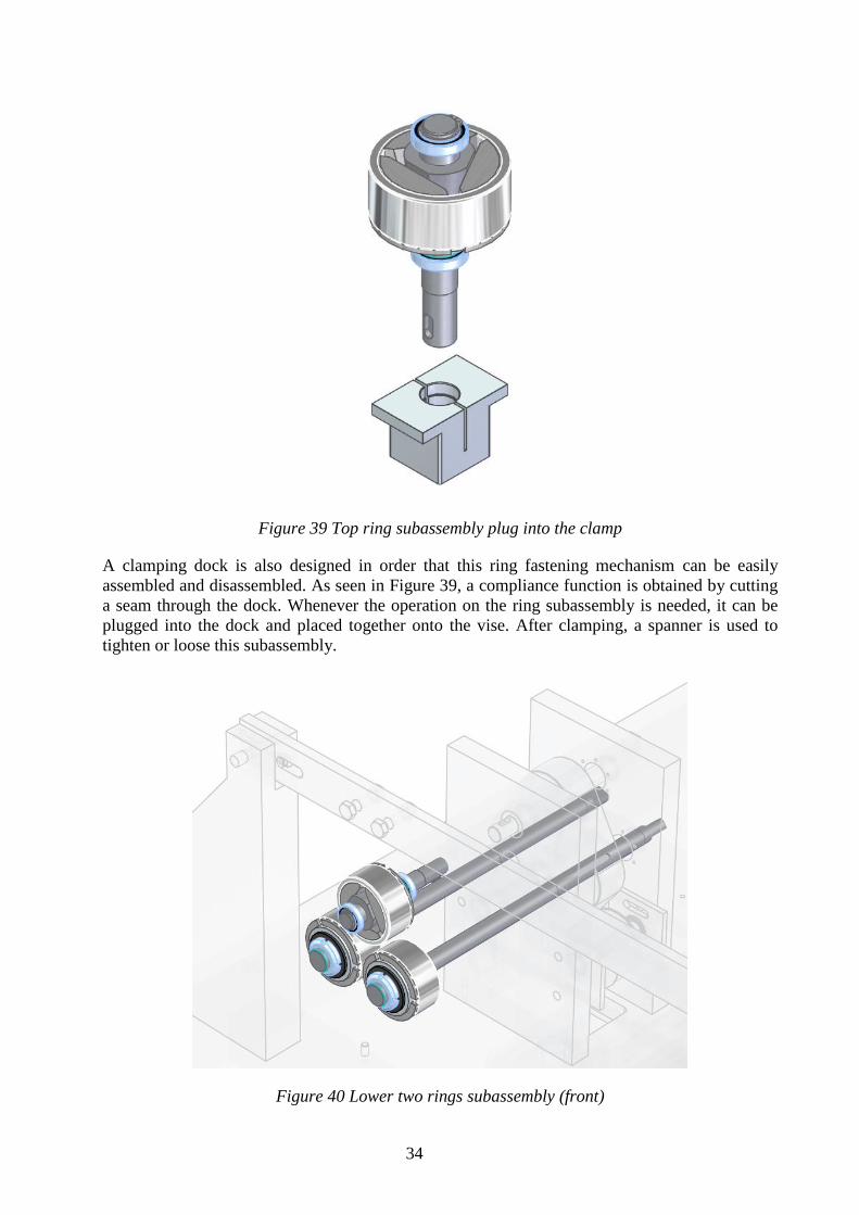
Figure 39 Top ring subassembly plug into the clamp
A clamping dock is also designed in order that this ring fastening mechanism can be easily
assembled and disassembled. As seen in Figure 39, a compliance function is obtained by cutting
a seam through the dock. Whenever the operation on the ring subassembly is needed, it can be
plugged into the dock and placed together onto the vise. After clamping, a spanner is used to
tighten or loose this subassembly.
Figure 40 Lower two rings subassembly (front)

35
Figure 41 Lower two rings subassembly (back)
Similarly, the lower two large rings can be fastening and locked with almost the same design.
The top ring subassembly has to be separate due to the loading situation. By flipping over the
configuration of upper design, the lower rings can be integrated with whole lower shafts. The
lower shaft has a flat tail end which is intended to be held by a wrench (Figure 41, Figure 42 ).
Therefore, rings assembling and disassembling can be done without taking down the lower
shafts. Finally, when all large rings and relevant components are assembled, they fit the current
test rig well as shown in Figure 42.
Figure 42 New design fits into the original configuration

36
4.6 Central ring mounting
The central specimen ring is also from the inner ring of a needle bearing. Since its diameter is
too small to use similar mechanism as the large ring, the interference fit is firstly considered. It is
essential to predict the resistance torque that the central ring has to overcome. In the designed
contacts, both rolling and sliding are supposed to exist. For pure sliding, the friction torque can
be calculated as:
𝑇 = 3 × 𝐹𝑓 ∙𝑑
2= 3 × 𝜇 𝑁 ∙
𝑑
2= 3 × 0.16 × 2200 × 0.0075 = 7.92 (𝑁𝑚) (11)
Where T is the friction torque that the central ring withstands; Ff is frictional force; d is diameter
of the central ring; µ is kinetic frictional coefficient; N is the normal force. As discussed
previously in chapter4.4, the loading force is 2.2KN. The coefficient of friction for lubricated
steel to steel surface is assumed as µ=0.16 according to the reference (Engineering toolbox,
2015). And there three contact positions around the ring circumference.
For pure rolling resistance, it is defined by the following equation:
𝐹𝑟 = 𝐶𝑟𝑟 𝑁 (12)
Where Fr is the rolling resistance force; Crr is coefficient of rolling friction. Since Crr is a rather
small value in the order of 10-4
(Wikipedia, 2015), the rolling resistance basically negligible.
Once the resistance torque is known, the required inference pressure can be obtained by dividing
the force by clamping area between the shaft and the central ring. And the diameter deviation of
shaft will be figured out according to equation(8). Then the shaft with accurate tolerances can be
machined. Besides, the ring needs to be heated up so that it is easily mounted or dismounted
without damaging both the shaft and ring. A bearing heater below is recommended. See Figure
43. The device has an adjustable temperature range of 50 - 200 °C (120 - 390 °F) (SKF-4, 2015).
Figure 43 An example bearing heater
It is not a problem to heat up the single ring before mounting. The challenge is how to heat up
the ring before dismounting, because the size is very small. Normally there is no stand tool for
dismounting this small inner ring from the shaft directly. A solution is shown in Figure 44 below.
Two half aluminum rings with a bore of the same dimension as the outer diameter. Those two
half rings can be heated up on the bearing heater plate first. Then the heated half rings are
clamped over the central ring. The heat will be transferred to the inner ring, which can be
removed without damage after a short while.

37
Figure 44 Two half rings in aluminium with a bore
There is also an alternative that is the oil injection method as shown in Figure 45. Dismounting
the bearing is made easier by pumping oil under pressure between the mating surfaces. Once the
oil pressure has built up, the component can be removed from the shaft with a minimum of effort
(SKF-3, 2015). If the shaft diameter is for example 12 mm, an M4 extension pipe will be needed.
Figure 45 Oil injection method schematic
4.7 Torque transducer support
A torque transducer was selected and purchased during the HK project (Figure 46). It measures
the transmission torque up to 25 Nm with nominal speed of 4000 rpm (AEP transducers, 2015).
This torque transducer is supposed to be perfectly aligned with the central shaft and the upper
motor shaft, which means the three shafts are in the same coaxial line.
A transducer support is needed in order that the alignment can be implemented based on it.
Therefore, it is firstly modelled in SE software according to the dimensions in the product data
sheet. The CAD model is then placed in the assembly environment. Finally the torque transducer

38
Figure 46 AEP torque transducer
support is finished as seen in Figure 47. It is designed in such a way that there is always margin
for the support with the transducer in vertical or horizontal plane. This is because the tunable
function is needed during the shaft alignment process. In fact, the design provides a so called
‘soft foot’ that allows the support structure to be adjusted along x, y and z axis. By loosing the
four larger screws on the base; shims can be added to each foot so that the vertical position is
slightly changed, the position along x can also be tuned due to the extra space around the bolts.
By loosing the two smaller screws form the sides, the whole support can move in z axis if needed.
Figure 47 Torque transducer support

39
Figure 48 Explosion view of the transducer support
From Figure 48, it can be seen that the transducer is mounted onto the top plate through which
four bolts are threaded from the bottom. The top is fastened on the vertical rib plates. The
material is milled out so that the lower weight will decrease the deformation of the footing plate.
The rib plate is fixed by two set screws sideways. This support is fairly flexible in general.
4.8 Shaft alignment solution
Aligning the central shaft is crucial to existence of the line contacts between test ring surfaces. In
this test rig, the alignment process is to align central shaft with the upper motor output shaft
within a tolerated margin. Perfectly aligned shafts are called to be collinear, which means that a
single straight line will define the center of both shafts. Since the error of the collinearity is
required to be in the order of micrometer, the task cannot be accomplished by regular ruler or
unaided eyes. In this section, two practical shaft alignment systems are introduced: the shaft
alignment tools based on proximity sensor and line laser.
Torque
transducer
Top plate
Rib plate
Footing plate
40
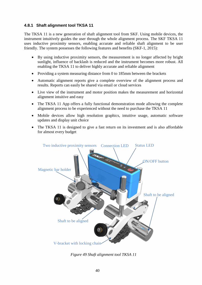
4.8.1 Shaft alignment tool TKSA 11
The TKSA 11 is a new generation of shaft alignment tool from SKF. Using mobile devices, the
instrument intuitively guides the user through the whole alignment process. The SKF TKSA 11
uses inductive proximity sensors, enabling accurate and reliable shaft alignment to be user
friendly. The system possesses the following features and benefits (SKF-1, 2015):
By using inductive proximity sensors, the measurement is no longer affected by bright
sunlight, influence of backlash is reduced and the instrument becomes more robust. All
enabling the TKSA 11 to deliver highly accurate and reliable alignment
Providing a system measuring distance from 0 to 185mm between the brackets
Automatic alignment reports give a complete overview of the alignment process and
results. Reports can easily be shared via email or cloud services
Live view of the instrument and motor position makes the measurement and horizontal
alignment intuitive and easy
The TKSA 11 App offers a fully functional demonstration mode allowing the complete
alignment process to be experienced without the need to purchase the TKSA 11
Mobile devices allow high resolution graphics, intuitive usage, automatic software
updates and display unit choice
The TKSA 11 is designed to give a fast return on its investment and is also affordable
for almost every budget
Figure 49 Shaft alignment tool TKSA 11
ON/OFF button
Status LED Connection LED
Magnetic bar holder
Two inductive proximity sensors
V-bracket with locking chain
Shaft to be aligned
Shaft to be aligned

41
Figure 50 TKSA 11used in the field
Figure 49and Figure 50 show the product components and its working status in the field.
4.8.2 Shaft alignment tool TKSA 41
The TKSA 41 is an advanced laser alignment solution for achieving accurate shaft alignments.
With two wireless measurement units, large sized detectors and powerful lasers, the instrument
performs precise measurements in even the most challenging conditions. The SKF TKSA 41 is
one of the industry’s best value alignment solutions (SKF-2, 2015).
Figure 51 TKSA 41 description
Figure 51 and Figure 52 show the product description and its working status. The features and
benefits of the system are listed as followed:

42
Wireless communication improves instrument handling and allows alignment of difficult
to reach applications from a safe position.
Free measurement allows alignment measurements to start at any angle and finish with
an angular sweep of just 90°.
Automatic measurement enables hands-free measurements by detecting the head
position and taking a measurement when the heads are rotated into the right position.
Automatic reports are generated after each alignment. The reports can be customised
with notes and pictures from the built-in camera for the most comprehensive overview.
All reports can be exported as pdf files.
Live view supports intuitive measurements and facilitates horizontal and vertical
alignments.
Machine library gives an overview of all machines and alignment reports. QR codes can
be used to further simplify machine identification and improve the alignment workflow.
Figure 52 TKSA 41used in the field
4.8.3 Alignment procedure for the test rig
The front end of central shaft is restricted by the three loaded large rings (Figure 53). The other
end is griped by the coupling. The positioning should be accurately identified for the collinearity.
Figure 53 The arrangement of the central shaft

43
By using one of the devices, the shaft alignment for the test rig can be implemented. The
following procedure is based on the operation instructions of SKF TKSA11. Firstly, install the
alignment tool on the central shaft and one side of the disk coupling as shown in Figure 54. Then
gradually tune the soft foot of transducer support by adding shims or slightly knocking until the
misalignment cannot be detected by the proximity sensors in vertical and in horizontal directions.
Figure 54 Alignment between central shaft and transducer
After that, the position of transducer and its support is used as a fixed reference. The upper
motor is now the adjustable end. Basically, the alignment between transducer and upper
motor shaft can be finished in the same way, despite more effort due to the motor weight.
Figure 55 Alignment between transducer and upper motor shaft

44
4.9 Housing design development
The housing design for the test rig has been constantly developed and improved. It is a chamber
that accommodates test specimens and lubricant working together. The sub-requirements for the
housing are listed as follows:
The housing is supposed to be easily installed and removed.
The internal space should be compact so that lubricant is used efficiently.
There are access to add lubricating oil or grease and way to drain the liquid.
The level of the oil inside the chamber should be visible.
There is no leakage when running the test
Figure 56 Housing of the test rig
The appearance of the final design is shown in Figure 56. A tempered glass is boldly utilized in
order that what happens inside can be observed. The glass withstands a high temperature
different up to 200 centigrade degree, which is necessary for the experiment.
Figure 57 presents all the composition of the housing design. When installing the housing onto
the vertical plate, the loading lever and fork must be lifted first. Then it is tighten by the screws
from the back of the plate. After pouring the oil from the top, the load arm can be put back
vertically. The grease can be also added by opening the front lid. The interior shape is cut
according to the envelope curves of the three- ring arrangement. On the bottom of the housing,
two through holes with threads will be machined. Two plugs with high temperature resistance
are used so that the liquid can be simply drained out of the chamber. O-ring and other seals are
employed around this housing, which will be discussed in the following section.

45
Figure 57 Explosion view of the housing design
4.10 Sealing arrangement
As can be seen clearly from Figure 58, the O-rings are frequently used in the housing. They exit
in all mating surfaces to prevent leakage. Each O-ringing is compressed during assembly in a
groove, which is defined by the standard reference from manufacturer.
Figure 58 O-ring seals for housing

46
Figure 59 Shaft seals on for housing
Since there are four shafts enter the housing, the interfaces need to be sealed too (Figure 59). In
accordance with the dimensions of the current design, lip seals and V-rings are put to use.
Figure 60 Lip seal for large-ring shaft
47
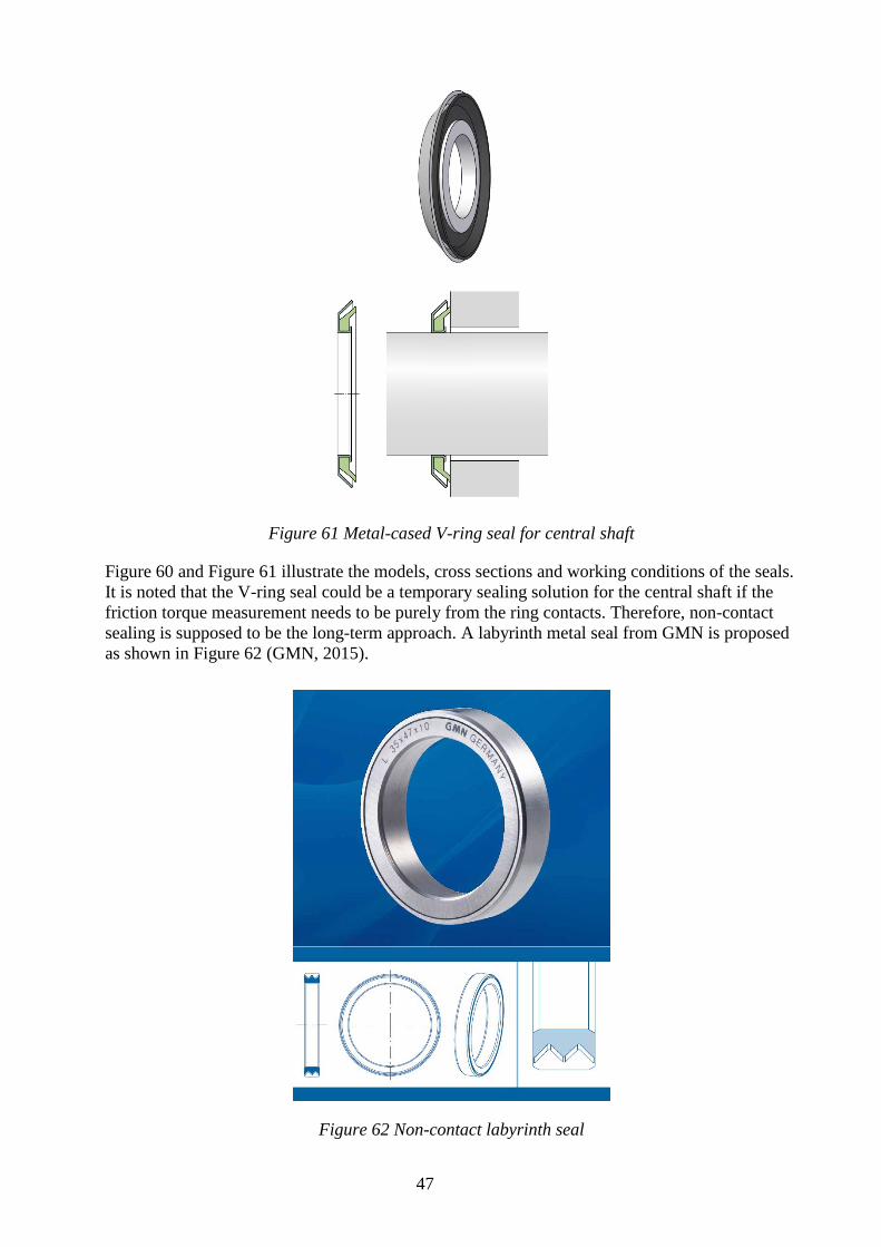
Figure 61 Metal-cased V-ring seal for central shaft
Figure 60 and Figure 61 illustrate the models, cross sections and working conditions of the seals.
It is noted that the V-ring seal could be a temporary sealing solution for the central shaft if the
friction torque measurement needs to be purely from the ring contacts. Therefore, non-contact
sealing is supposed to be the long-term approach. A labyrinth metal seal from GMN is proposed
as shown in Figure 62 (GMN, 2015).
Figure 62 Non-contact labyrinth seal

48
5 RESULTS
The final results of the design and are described in this chapter. The technical Specifications of
the product are also tabulated.
After disassembling previous test rig and reprocessing the relevant parts, the machine is finally
reassembled as showcased in Figure 63. The new test run indicates a stable, quieter and well
performed working status, which basically achieves the outcome as expected.
Figure 63 Micropitting test rig assembly
The main technical specifications of the test rig are given in Table 1.
Table 1. Main technical specifications
Maximum load 2.2 KN
Maximum pressure 1.2Gpa (Line contact), 4Gpa (Elliptic contact)
Maximum circular velocity 4 m/s
Slide to roll ratio (SRR) 0% to +/- 200 %
Permissible lubricant temperature 100 º C
Ambient temperature -20 to 40 º C
Maximum Roller Torque 20 Nm
Power input 200-240 V AC / 3 Phase 380V
Width 76 cm (incl. lever)
Length 106cm
Height 131cm
Weight Approx 180Kg
Noise level < 60dB
49
6 DISCUSSION AND CONCLUSIONS
A discussion and the conclusions are presented in this chapter. The conclusions are based from
the scope and challenges before this thesis project started.
6.1 Discussion
The project targeted at developing a test-rig which can be used for pitting and micropitting
research. It is basically achieved, except some future work due to the tine constrain. Before this
work started, the test-rig was not fully functioning. There were several core problems need to be
solved. The machine now at the end of this project can be said to be in an operational status. This
thesis work is implemented from the previous work and available resources. Some issues are
discussed a little further as follows.
The load applied is limited to 2.2 KN, which result in 1.2G pa line contact pressure. This is due
to the previous design for an elliptic contact, which can achieve 4 Gpa by loading around
500KN. But it has to use specific test sample that requires extra hardening and heat treatment.
Since the length of line contact increases, higher loading is needed for higher contact pressure.
However, the bearing and the relevant components have been customized and manufactured. The
current load for line contact is based on the prior loading mechanism which can be improved.
The highest permissible temperature is preset to 100 º C, which is also the restriction of the
loaded bearing inside the chamber. The higher the working temperature is, the shorter life the
bearing has. Using larger bearing definitely raise temperature limit.
In this work, some corrective measure are taken regarding the shafts locating and bearing
arrangement. The main reason is to save more effort and avoid re-machining many parts. If
redesign is carried out, the bearing housing and shaft shoulders should be considered in detail.
The central shaft alignment solution is given in Chapter 4.8. There is still wobbling on central
shaft, because the alignment work has not been accomplished yet. Once the shaft alignment tool
starts to help, this problem can be solved as it is presented.
The torque transducer should not be put to use directly unless the real torque is confirmed to be
less than its measuring range. Before connect the transducer into the system, the central is
supposed to aligned with motor first. After system runs smoothly, the transducer can be aligned
and connected with the central shaft and the motor. The load should also be applied gradually
when measuring the torque.
A large ring fastening mechanism has been developed. This design only is only applied on the
top ring for test purpose, which proved to be feasible. It applies to the lower two rings as well.
As a matter of fact, this design can even be optimized in terms of easier manufacturing.
Regarding the O-rings design showed in Chapter 4.10, the profiles are irregular in comparison
with the standard products. They are supposed to be either customized from the manufacturer or
self-made by gluing the regular ones. The V-ring seal is temporarily used for axial sealing. It is
relatively easier to install but creating extra friction. When accurately measuring the friction
torque only from the ring contact, the suggested metal labyrinth seal should be installed.
Nevertheless, the V-ring seal can be placed in front of the labyrinth seal with sufficient distance.
The metal case of V-ring seal protects the labyrinth seal against strong and direct splashing
liquids.
50
6.2 Conclusions
By verifying the project purposes, scope and the challenges at the beginning, the conclusions can
be drawn as follows,
The line contacts between specimen surfaces are ensured.
The way of fastening and replacing the test rings is user-friendly.
Bearings arrangement and shaft positioning are completed.
Loading mechanism has been improved.
Belt locating has been adjusted properly.
Interference between belt tensioner shaft and support plate is eliminated.
Housing modification and sealing have been provided.
Shaft alignment solution and the transducer support design are given.
Manufacturing, purchasing, assembling and test runs have been carried out.
In summary, this thesis work turns out a cost-effective way of developing micro-pitting test ring.
Because of the accelerated test design, it can definitely decrease the experiment time cost in
contrast with the FAG test rig. And it is more user friendly than the existing machines in terms of
the test specimens handling. All the specimens are the standard spare parts, which don’t require
extra treatment. The test sample is easy and quick to be mounted and replaced. In addition, this
thesis work also provides feasible solutions for other crucial problems which can be the
foundation for the future work.

51
7 RECOMMENDATIONS AND FUTURE WORK
In this chapter, recommendations on more detailed solutions and future work in this field are
presented.
7.1 Recommendations
Here are some recommendations which could be taken into account or implemented if necessary.
The load fork could be redesigned to accommodate larger bearing with higher static and dynamic
load rating. The load lever could be lengthened to a certain extent so that a bigger ratio is
available. Besides, there are more load applying methods other than dead weight. Hydraulic
cylinder and linear actuator could be the alternatives.
There are three vertical supporting plates that can be improved by increasing the width. Wider
plates provide more stably supporting. Moreover; larger mating surface between the housing and
first vertical plate will be available, which makes housing installation and sealing easier
Apart from the transducer support design, a 3-axis adjustable platform could also be an option.
The positioning of this platform can be tuned along x, y and z axis separately. The resolution can
be down to 50 µm/rev with fine thread, which is convenient for the shaft aligning process.
The motors used now are the AC induction motors which can be replaced by servo motor with
low inertia and accurate control.
Since the temperature of the test lubricant is high, cooling devices should be considered. It can
give quick access to the test sample after each test.
In the sense of being user friendly, a shelf beneath the table should be provided to place relevant
things such as motor encoder, tools and spare parts. Lower beams between the four table legs
should be added so that the whole machine can be lift and moved by a pallet jack.
7.2 Future work
The future work of this project is considered to be the following issues:
Completing shaft alignment when the assistant tool is in place.
Necessary sensors selection and the corresponding design for installing.
An emergency stop button should be added.
Data acquisition interface design.
Computer control circuit design.
More test runs and diagnoses

52
8 REFERENCES
AEP transducers, 2015. RT2 torque transducer Data Sheet, Cognento: s.n.
Amarnath, M., Sujatha, C. & Swarnamani, S., 2009. Experimental studies on the effects of
reduction in gear tooth stiffness and lubricant film thickness in a spur geared system. Tribology
International, Volume 42, p. 340–352.
ATSB, 2000. Technical Analysis Report " Short Bros. SD360-300, VH-SUM. [Online]
Available at: www.atsb.gov.au/publications/2000/tr200003399.aspx
[Accessed 11 2015].
Baker, R., 2008. Effect of Additives on Macropitting Failure Using a Three Contact Disc Rig.
[Online]
Available at: www.pcs-instruments.com/mpr/mpr.shtml
[Accessed 9 2014].
Beek, A. v., 2009. Advanced engineering design, lifetime performance and reliability. 2009 ed.
TU Delft: 216.
Engineering toolbox, 2015. Friction and Coefficients of Friction. [Online]
Available at: http://www.engineeringtoolbox.com/friction-coefficients-d_778.html
[Accessed 11 2015].
GMN, 2015. GMN seal catalogue, Nuremberg: LMmedia.
Kahraman, A., 2012. An Experimental and Theoretical Investigation of Micro-pitting in Wind
Turbine Gears and Bearings, Columbus: The Ohio State University.
Kotzalash, M. N. & Doll, G. L., 2010. Tribological advancements for reliable wind turbine
performance. Phil. Trans. R. Soc., Volume 368, p. 4829–4850.
Laine, E., Olver, A. V. & Beveridge, T. A., 2008. Effect of lubricants on micropitting and wear.
Tribology International, Volym 41, pp. 1049-1055.
Machine Design Department, 2008. Machine element handbook. Stockholm: KTH.
Martins, R., Locatelli, C. & Seabra, J., 2011. Evolution of tooth flank roughness during gear
micropitting tests. Industrial Lubrication and Tribology, Volume 63, pp. 34-45.
SKF-1, 2015. Shaft alignment tool TKSA 11. [Online]
Available at: http://www.skf.com/group/products/maintenance-products/alignment-tools/shaft-
alignment-tools/shaft-alignment-tool-tksa11/index.html
[Accessed 11 2015].
SKF-2, 2015. Shaft alignment tool TKSA 41. [Online]
Available at: http://www.skf.com/group/products/maintenance-products/alignment-tools/shaft-
alignment-tools/shaft-alignment-tool-tksa41/index.html
[Accessed 11 2015].
SKF-3, 2015. SKF Oil Injection Method. [Online]
Available at: http://www.skf.com/group/products/maintenance-products/hydraulic-tools-for-
mounting-and-dismounting/skf-oil-injection-method/index.html
[Accessed 11 2015].
SKF-4, 2015. Electric hot plate. [Online]
Available at: http://www.skf.com/caribbean/products/maintenance-products/bearing-
heaters/heaters-for-mounting/electric-hot-plate/index.html
[Accessed 11 2015].

53
SKF-5, 2015. Materials for bearing rings and rolling elements. [Online]
Available at: http://www.skf.com/group/products/bearings-units-housings/super-precision-
bearings/principles/bearing-specifics/materials/index.html
[Accessed 11 2015].
Stachowiak, G. W. & Batchelor, A. W., 2014. Chapter 7. In: Engineering Tribology.
s.l.:Elsevier, pp. 357-358.
Stadtfeld, H. J., 1996. The Next Step in Bevel Gear Metrology. Gear technology, 01/02, pp. 18-
23.
Strama-MPS, 2015. FZG gear test rig. [Online]
Available at: www.strama-mps.de/en/product-portfolio/test-rigs/standards/fzg-gear-test-rig.html
[Accessed 11 2015].
The Ohio State University, 2013. Open Access Theses and Dissertations. [Online]
Available at:
oatd.org/oatd/record?record=oai%5C%3Aetd.ohiolink.edu%5C%3Aosu1365695328
[Accessed 11 2015].
tribology-abc, 2015. Calculator for disc compression springs. [Online]
Available at: www.tribology-abc.com
[Accessed 11 2015].
University of Leoben, 2015. Electromechanical dynamometer. [Online]
Available at: amb.unileoben.ac.at/de/2264/
[Accessed 11 2015].
VibrAlign, 2015. Shaft alignment concepts. [Online]
Available at: http://vibralign.com/resources/concepts/
[Accessed 11 2015].
Wang, P. et al., 2013. Experimental Research on Anti-micropitting Property of Lubricating Oil.
Lubricating oil, 28(4), pp. 42-47.
Wedeven Associates, Inc, 2015. WAMmp - Micropitting. [Online]
Available at: wedeven.com/wammp.html
[Accessed 2015 11].
Wikipedia, 2015. Rolling resistance. [Online]
Available at: Rolling resistance
[Accessed 11 2015].

54
APPENDIX A: PROJECT TIME PLAN

55
APPENDIX B: REQUIREMENT SPECIFICATIONS

56
APPENDIX C: MATLAB PROGRAM CODE
The appendix or appendices is the natural place for detailed or supplementary information that
would make the thesis less easy to read if they were given in the previous chapter. Please, give
each appendix a suitable title.
%% Elliptic contact (ellipressgeo) function
function [a,b,pm,surv1,surv2,sl2ro_ra]=
ellipressgeo(R1x,R1y,R2x,R2y,E1,E2,v1,v2,F,rpm1,rpm2) [a,b,delta,pm,k]=ellips(R1x,R1y,R2x,R2y,E1,E2,v1,v2,F);
R1x=R1x*1000; R2x=R2x*1000;
figure x0=linspace(-R2x,R2x,100);
y0=sqrt(R2x^2-x0.^2); plot(x0,y0,'r','linewidth',2)
hold on plot(x0,-y0,'r','linewidth',2)
axis equal
set(gca,'Xlim',[-2*R2x-2*R1x 2*R2x+2*R1x],'Ylim',[-2*R1x 2*R2x+2*R1x]) x1=linspace(-R1x,R1x,100);
y1=sqrt(R1x^2-x1.^2); plot(x1,y1+R1x+R2x,'k','linewidth',2)
plot(x1,-y1++R1x+R2x,'k','linewidth',2) [x2,y2]=rotxy(0,0,pi*2/3,x1,y1+R1x+R2x);
[x02,y02]=rotxy(0,0,pi*2/3,x1,-y1+R1x+R2x); plot(x2,y2,'g','linewidth',2)
plot(x02,y02,'g','linewidth',2) [x3,y3]=rotxy(0,0,-pi*2/3,x1,y1+R1x+R2x);
[x03,y03]=rotxy(0,0,-pi*2/3,x1,-y1+R1x+R2x); plot(x3,y3,'b','linewidth',2)
plot(x03,y03,'b','linewidth',2) omg1=rpm1*2*pi/60;
omg2=rpm2*2*pi/60;
surv1=omg1*R1x/1000; surv2=omg2*R2x/1000;
dv=surv1-surv2; if abs(surv1)>=abs(surv2)
sl2ro_ra=dv/surv1*100; else
sl2ro_ra=dv/surv2*100; end
text(0,0.5*R2x,['sv2=' num2str(surv2)]) text(0,1.5*R2x,['sv1=' num2str(surv1)])

57
%% Ellips funtion
function [a,b,delta,p0,k]=ellips(R1x,R1y,R2x,R2y,E1,E2,ny1,ny2,P) % Calculates hertzian elliptical contact results.
% [a,b,delta,p0,k]=ellips(R1x,R1y,R2x,R2y,E1,E2,ny1,ny2,P); % saves the results in the parameters a b delta p0 and k (k=a/b or b/a).
% ellips(R1x,R1y,R2x,R2y,E1,E2,ny1,ny2,P); % writes the results on the screen.
E=((1-ny1^2)/E1+(1-ny2^2)/E2)^(-1); Rp=(1/R1x+1/R2x)^(-1);
Rpp=(1/R1y+1/R2y)^(-1);
Re=sqrt(Rp*Rpp);
if Rpp < Rp H=Rp/Rpp; else H=Rpp/Rp; end if H==1
k=1; else
k=(H)^(-2/3); if ellipsf(k)>H k=[1-eps k]; else k=[1e-6 k]; end
F=ellipsf(k); % KLJ (4.28) while abs((H-F(length(F)))/H)>1e-10
v=find(F<H); [m I2]=max(F(v)); I2=v(I2); v=find(F>H); [m I1]=min(F(v)); I1=v(I1);
k=[k k(I1)-(k(I1)-k(I2))/(F(I1)-F(I2))*(F(I1)-H)]; %Sekantmetoden F=[F ellipsf(k(length(k)))];
end
end k=k(length(k));
c=(3*P*Re/4/E)^(1/3)*ellipsf1(k); a=c/sqrt(k);
b=c*sqrt(k); delta=(9*P^2/16/E^2/Re)^(1/3)*ellipsf2(k);
p0=(6*P*E^2/pi^3/Re^2)^(1/3)*ellipsf1(k)^(-2); if Rpp>Rp t=a;a=b;b=t; end
if nargout==0 disp([' a = ' num2str(a) ' (2a = ' num2str(2*a) ') mm'])
disp([' b = ' num2str(b) ' (2b = ' num2str(2*b) ') mm']) disp(['delta = ' num2str(1e3*delta) ' um'])
disp([' p0 = ' num2str(p0) ' MPa']) end
function f=ellipsf(k) [K E]=ellipke((1-k.^2));
f=(E./k.^2-K)./(K-E);

58
function f1=ellipsf1(k) if k==1
f1=1; else
e2=(1-k^2); [K E]=ellipke(e2);
f1=(4/pi/e2*k^(3/2)*((E/k^2-K)*(K-E))^(1/2))^(1/3); end
function f2=ellipsf2(k)
if k==1
f2=1; else
e2=(1-k^2); [K E]=ellipke(e2);
f2=2/pi*k^(1/2)*K*ellipsf1(k)^(-1); %(1/3); end
%% Rotxy funtion function [xn,yn]=rotxy(x0,y0,alfa,x,y)
% [xn,yn]=rotxy(x0,y0,alfa,x,y); % Rotates the points (x,y) the angle alfa around the point (x0,y0).
xn=x0+(x-x0)*cos(alfa)-(y-y0)*sin(alfa); yn=y0+(x-x0)*sin(alfa)+(y-y0)*cos(alfa);
%% Line contact calculation clear;
clc; E1=210e9
E2=210e9 v1=0.3
v2=0.3 R1=30e-3
R2=7.5e-3 l=11.4 % real contact length
%l=10 Fpl=3500/l*1000 %contact load F/l
EE = 1 / ( (1-v1*v1) / (2*E1) + (1-v2*v2) / (2*E2) ) RR = 1 / ( 1 / R1 + 1 / R2 )
b=((8*Fpl*RR)/(pi*EE))^0.5 pm=Fpl/(2*b)
pmax=4/pi*pm

59
APPENDIX D: LIST OF FIGURES
Figure 1 Microphotograph of pitting and micropitting ............................................................... 13
Figure 2 Pitting on gear teeth and Micropitting on bearing inner raceway .................................. 13
Figure 3 FZG gear test rig ............................................................................................................. 14
Figure 4 FZG main components .................................................................................................... 15
Figure 5 Twin-disk test machine ................................................................................................... 15
Figure 6 Close-up view of the set-up ............................................................................................ 16
Figure 7 MPR schematic ............................................................................................................... 16
Figure 8 MPR three ‘counterface’ rings ........................................................................................ 17
Figure 9 WAMmp - Micropitting machine ................................................................................... 17
Figure 10 WAMmp test chamber .................................................................................................. 18
Figure 11 Nominal line contact ..................................................................................................... 18
Figure 12 Interference fits ............................................................................................................. 20
Figure 13 Disc spring compression ............................................................................................... 20
Figure 14 Perfectly aligned shafts ................................................................................................. 21
Figure 15 Types of Misalignment ................................................................................................. 21
Figure 16 Adjust the machine in the vertical plane ....................................................................... 22
Figure 17 Adjust the machine in the horizontal plane .................................................................. 22
Figure 18 Test rig assembly at the end of HK course ................................................................... 23
Figure 19: The geometry of three-contact configiguration ........................................................... 24
Figure 20 Main structure ............................................................................................................... 24
Figure 21 Parallel rings arrangement ............................................................................................ 25
Figure 22 Power-train subassembly .............................................................................................. 25
Figure 23 Loading mechanism ...................................................................................................... 25
Figure 24 Flex coupling connects two shafts ................................................................................ 26
Figure 25 Press fit for the large ring fastening .............................................................................. 27
Figure 26 Lower motor fastened by long screws through table ribs ............................................. 28
Figure 27 Lower motor mounting plate and bracket ..................................................................... 28
Figure 28 Retaining rings mounted on both shafts ....................................................................... 29
Figure 29 Specific slots are milled on the supporting plates ......................................................... 29
Figure 30 Shaft and bearing arrangement before modification ..................................................... 30
Figure 31 Shaft and bearing arrangement after modification ....................................................... 30
Figure 32 Double universal joints ................................................................................................. 31
60
Figure 33 Universal joints connect two top shafts ........................................................................ 31
Figure 34 Flexibility of the loading lever ...................................................................................... 32
Figure 35 Large test ring from needle bearing .............................................................................. 32
Figure 36 Wedge profile design .................................................................................................... 33
Figure 37 Explosion view of the top ring subassembly ................................................................ 33
Figure 38 Top ring subassembly ................................................................................................... 33
Figure 39 Top ring subassembly plug into the clamp ................................................................... 34
Figure 40 Lower two rings subassembly (front) ........................................................................... 34
Figure 41 Lower two rings subassembly (back) ........................................................................... 35
Figure 42 New design fits into the original configuration ............................................................ 35
Figure 43 An example bearing heater ........................................................................................... 36
Figure 44 Two half rings in aluminium with a bore ..................................................................... 37
Figure 45 Oil injection method schematic .................................................................................... 37
Figure 46 AEP torque transducer .................................................................................................. 38
Figure 47 Torque transducer support ............................................................................................ 38
Figure 48 Explosion view of the transducer support ..................................................................... 39
Figure 49 Shaft alignment tool TKSA 11 ..................................................................................... 40
Figure 50 TKSA 11used in the field ............................................................................................. 41
Figure 51 TKSA 41 description .................................................................................................... 41
Figure 52 TKSA 41used in the field ............................................................................................. 42
Figure 53 The arrangement of the central shaft ............................................................................ 42
Figure 54 Alignment between central shaft and transducer .......................................................... 43
Figure 55 Alignment between transducer and upper motor shaft ................................................. 43
Figure 56 Housing of the test rig ................................................................................................... 44
Figure 57 Explosion view of the housing design .......................................................................... 45
Figure 58 O-ring seals for housing ................................................................................................ 45
Figure 59 Shaft seals on for housing ............................................................................................. 46
Figure 60 Lip seal for large-ring shaft .......................................................................................... 46
Figure 61 Metal-cased V-ring seal for central shaft ...................................................................... 47
Figure 62 Non-contact labyrinth seal ............................................................................................ 47
Figure 63 Micropitting test rig assembly ...................................................................................... 48