Delta IV Payload Planners Guide
270
MDC 99H0065 October 1999 Delta IV Payload Planners Guide Delta IV Payload Planners Guide
Transcript of Delta IV Payload Planners Guide
MDC 99H0065 October 1999
Delta IV PayloadPlanners GuideDelta IV PayloadPlanners Guide
The Boeing Company5301 Bolsa Avenue, Huntington Beach, CA 92647-2099 (714) 896-3311
OCTOBER 1999 MDC 99H0065
DELTA IVPAYLOAD PLANNERS GUIDE
The Delta IV Payload Planners Guide has been cleared for public release by the Chief—Air Force Division,Directorate for Freedom of Information and Security Review, Office of the Assistant Secretary of Defense, as stated in
letter 99-S-3495, dated 13 October 1999.
Copyright 1998, 1999 by The Boeing Company. All rights reserved under the copyright laws by The Boeing Company.
02716REU9.1
TO HOLDERS OF THE DELTA IV PAYLOAD PLANNERS GUIDE
REVISION SERVICE CARDDELTA IV PAYLOAD PLANNERS GUIDE
MDC 99H0065 October 1999
CURRENT ADDRESS
Name:Title:Department:Mail Stop:Telephone:Fax:E-mail:Company Name:Address:City:State:Zip Code:Country:Date:
Check all that apply:
Customer Comments:
Send hardcopy of next revision
Send CD-ROM of next revision
Address change
Delta Launch Servicesc/o The Boeing Company5301 Bolsa Avenue, (MC H014-C426)Huntington Beach, CA 92647-2099E-mail: [email protected]
The Delta IV Payload Planners Guide will be revised periodically to incorporate the latest information. You are encouraged to return the Revision Service Card below to ensure that you are included on the mailing list for future revisions of the Delta IV Payload Planners Guide. Changes to your address should be noted in the space provided.
Please forward any comments or suggestions you have concerning content or format. Inquiries to clarify or interpret this material should be directed to:
BUSINESS REPLY MAILFIRST CLASS PERMIT NO. 41, HUNTINGTON BEACH, CA
POSTAGE WILL BE PAID BY ADDRESSEE
NO POSTAGENECESSARY
IF MAILEDIN THE
UNITED STATES
Delta Launch Servicesc/o The Boeing Company5301 Bolsa Avenue, MC H014-C426Huntington Beach, CA 92647-2099
iii/iv
PREFACE
This Delta IV Payload Planners Guide (PPG) is issued to the spacecraft user community to provide
information about the Delta IV family of launch vehicles and their related systems and launch services.
This document contains current information on Boeing plans for Delta IV launch services in addition
to current projections related to the Delta launch vehicle specifications. Included are Delta IV family
vehicle descriptions, target vehicle performance figures, payload envelopes, anticipated spacecraft envi-
ronments, mechanical and electrical interfaces, payload processing, and other related information of
interest to our potential customers.
As the Delta IV development program progresses, The Boeing Company will periodically update the
information presented in the following pages. To this end, you are urged to promptly mail back the
enclosed Readers Service Card so that you will be sure to receive any updates as they become available.
Recipients are also urged to contact Boeing with comments, requests for clarification, or amplification
of any information in this document.
General inquiries regarding launch service availability and pricing should be directed to:
Delta Launch Services Inc.
Phone: (714) 896-3294
Fax: (714) 896-1186
E-mail: [email protected]
Inquiries regarding the content of the Delta IV Payload Planners Guide should be directed to:
Delta Launch Services Customer Program Development
Phone: (714) 896-5195
Fax: (714) 372-0886
E-mail: [email protected]
Mailing address:
Delta Launch Services
c/o The Boeing Company
5301 Bolsa Avenue
Huntington Beach, CA 92647-2099
U.S.A.
Attn: H014-C426
Visit us at our Delta IV Web site: www.boeing.com/defense-space/space/delta/delta4/delta4.htm
McDonnell Douglas Corporation currently operates as a separate legal entity and subsidiary of The Boeing Company.References in this document to “McDonnell Douglas Corporation” or “McDonnell Douglas Aerospace” refer to thissubsidiary.
v
CONTENTS
GLOSSARY xxiii
INTRODUCTION 1
Section 1 LAUNCH VEHICLE DESCRIPTION 1-11.1 Delta Launch Vehicles 1-11.2 Delta IV Launch System Description 1-11.2.1 First Stage 1-31.2.2 Second Stage 1-61.2.3 Third Stage 1-71.2.4 Payload Attach Fittings 1-71.2.5 Payload Fairings 1-81.2.6 Dual-Manifest Capability 1-81.2.7 Avionics and Flight Software 1-101.3 Delta IV Vehicle Coordinate System 1-111.3.1 Orientation 1-111.3.2 Station Number 1-111.4 Launch Vehicle Insignia 1-11
Section 2 GENERAL PERFORMANCE CAPABILITY 2-12.1 Launch Sites 2-12.1.1 East Coast Launch Site 2-12.1.2 West Coast Launch Site 2-12.2 Mission Profiles 2-12.2.1 GTO Mission Profile 2-22.2.2 LEO Mission Profile 2-22.2.3 GEO Mission Profile 2-32.2.4 Delta IV Heavy Dual-Manifest GTO Mission Profile 2-32.2.5 Multiple-Manifest Mission Profile 2-52.3 Performance Summaries 2-62.3.1 Delta IV Medium Vehicle 2-82.3.2 Delta IV Medium-Plus (4,2) Vehicle 2-92.3.3 Delta IV Medium-Plus (5,2) Vehicle 2-92.3.4 Delta IV Medium-Plus (5,4) Vehicle 2-92.3.5 Delta IV Heavy Vehicle 2-92.4 Orbital Accuracy 2-46
Section 3 PAYLOAD FAIRINGS 3-13.1 General Description 3-13.2 4-m and 5-m-dia Composite Payload Fairing 3-13.3 5-m-dia Metallic Payload Fairing 3-7
Section 4 PAYLOAD ENVIRONMENTS 4-14.1 Prelaunch Environments 4-1
vi
4.1.1 Air-Conditioning 4-14.1.2 MST Enclosure 4-24.1.3 Radiation and Electromagnetic Environments 4-34.1.4 Electrostatic Potential 4-54.1.5 Contamination and Cleanliness 4-54.2 Launch and Flight Environments 4-74.2.1 Fairing Internal Pressure Environment 4-74.2.2 Thermal Environment 4-114.2.2.1 Payload Fairing Thermal Environment 4-114.2.2.2 On-Orbit Thermal Environment 4-134.2.2.3 Payload/Launch Vehicle Interface 4-134.2.2.4 Stage-Induced Thermal Environments 4-134.2.2.5 In-Flight Contamination Environments 4-134.2.3 Flight Dynamic Environment 4-144.2.3.1 Steady-State Acceleration 4-144.2.3.2 Combined Loads 4-144.2.3.3 Acoustic Environment 4-214.2.3.4 Sinusoidal Vibration Environment 4-224.2.3.5 Shock Environment 4-244.2.4 Spacecraft Qualification and Acceptance Testing 4-274.2.4.1 Structural Load Testing 4-284.2.4.2 Acoustic Testing 4-284.2.4.3 Sinusoidal Vibration Testing 4-284.2.4.4 Shock Testing 4-314.2.5 Dynamic Analysis Criteria and Balance Requirements 4-314.2.5.1 Two-Stage Missions 4-31
Section 5 PAYLOAD INTERFACES 5-15.1 Heritage Design Philosophy 5-15.1.1 Structural Design 5-15.1.2 Mechanical Design 5-15.2 Delta IV Payload Attach Fittings 5-25.2.1 1666-mm (66-in.) Payload Interface—1666-4 and 1666-5 PAFs5-35.2.2 1194-mm (47-in.) Payload Interface—1194-4 and 1194-5 PAFs5-35.2.3 937-mm (37-in.) Payload Interface—937-4 and 937-5 PAFs5-55.2.4 1664-mm (66-in.) Payload Interface—1664-4 and 1664-5 PAFs5-75.2.5 1575-4 PAF 5-85.2.6 4394-5 PAF 5-85.2.7 Payload Mass vs Center-of-Gravity Location Capabilities 5-85.2.8 Other Payload Attach Fittings 5-105.3 Delta IV Electrical Interfaces 5-115.3.1 Ground-to-Payload Functions 5-145.3.2 Launch-Vehicle-to-Payload Functions 5-165.3.2.1 Ordnance Discretes 5-165.3.2.2 28-VDC Command Discretes or Switch Closures 5-165.3.2.3 Breakwire Separation Monitors 5-17
vii
5.3.2.4 Telemetry Channels 5-175.3.3 Spacecraft Connectors 5-175.3.4 Customer Wiring Documentation 5-17
Section 6 LAUNCH OPERATIONS AT EASTERN RANGE 6-16.1 Organizations 6-16.2 Facilities 6-16.2.1 Astrotech Space Operations Facilities 6-36.2.1.1 Astrotech Building 1/1A (PPF) 6-56.2.1.2 Astrotech Building 2 (HPF) 6-86.2.1.3 Astrotech Building 3 (Environmental Storage Facility) 6-96.2.1.4 Astrotech Building 4 (Warehouse Storage Facility) 6-96.2.1.5 Astrotech Building 5 (Owner/Operator Office Area) 6-126.2.1.6 Astrotech Building 6 (Fairing Support Facility) 6-126.2.1.7 Astrotech Building 7 (Boeing Office Area) 6-126.2.1.8 Astrotech Building 8 (Launch Operations Storage Building)6-126.2.1.9 Astrotech Building 9 (Delta IV Payload Processing Facility)6-126.2.1.10Spacecraft Long-Term Storage 6-126.2.2 CCAS Operations and Facilities 6-136.2.2.1 Cape Canaveral Industrial Area 6-136.2.3 Delta Operations Center 6-136.2.4 Solid-Propellant Storage Area, CCAS 6-146.2.4.1 Storage Magazines, CCAS 6-146.2.4.2 Electrical-Mechanical Testing Facility, CCAS 6-156.3 Spacecraft Encapsulation and Transport to the Launch Site6-156.4 Space Launch Complex 37 6-176.4.1 Mobile Service Tower 6-206.4.2 Common Support Building 6-206.4.3 Support Equipment Building 6-236.4.4 Horizontal Integration Facility 6-236.4.5 Launch Control 6-266.5 Support Services 6-266.5.1 Launch Support 6-266.5.1.1 Mission Director Center (MDC) 6-266.5.1.2 Launch Decision Process 6-276.5.2 Weather Constraints 6-276.5.2.1 Ground-Wind Constraints 6-276.5.2.2 Winds-Aloft Constraints 6-276.5.2.3 Weather Constraints 6-276.5.2.4 Lightning Activity 6-286.5.3 Operational Safety 6-286.5.4 Security 6-286.5.4.1 CCAS Security 6-286.5.4.2 Launch Complex Security 6-296.5.4.3 Astrotech Security 6-296.5.5 Field-Related Services 6-29
viii
6.6 Delta IV Plans and Schedules 6-296.6.1 Mission Plan 6-296.6.2 Integrated Schedules 6-296.6.3 Launch Vehicle Schedules 6-326.6.4 Spacecraft Schedules 6-336.7 Delta IV Meetings and Reviews 6-336.7.1 Meetings 6-346.7.2 Prelaunch Review Process 6-366.7.2.1 Postproduction Review 6-366.7.2.2 Mission Analysis Review 6-366.7.2.3 Pre-Vehicle-On-Stand Review 6-366.7.2.4 Flight Readiness Review 6-366.7.2.5 Launch Readiness Review 6-36
Section 7 LAUNCH OPERATIONS AT WESTERN RANGE 7-17.1 Organizations 7-17.2 Facilities 7-17.2.1 NASA Facilities on South VAFB 7-47.2.1.1 Spacecraft Laboratory 7-47.2.2 Astrotech Space Operations Facilities 7-67.2.2.1 Astrotech Building 1032 (Payload Processing Facility) 7-77.2.2.2 Astrotech Building M1030 (Technical Support Building) 7-97.2.2.3 Astrotech Building 1028 (Communications Support Building)7-97.2.3 Spaceport Systems International 7-97.2.3.1 Processing Areas 7-107.2.3.2 Technical Support Areas 7-127.3 Payload Encapsulation and Transport to Launch Site 7-127.3.1 Payload Processing Facility Analysis for Delta IV
Encapsulation 7-187.4 Space Launch Complex 6 7-197.4.1 Mobile Service Tower 7-207.4.2 Common Support Building 7-217.4.3 Integrated Processing Facility 7-217.4.4 Support Equipment Building 7-217.4.5 Horizontal Integration Facility 7-227.4.6 Range Operations Control Center 7-257.5 Support Services 7-257.5.1 Launch Support 7-257.5.1.1 Mission Director Center (Building 840) 7-257.5.1.2 Building 8510 Remote Launch Control Center (RLCC) 7-267.5.1.3 Launch-Decision Process 7-267.5.2 Weather Constraints 7-277.5.2.1 Ground-Wind Constraints 7-277.5.2.2 Winds-Aloft Constraints 7-277.5.2.3 Weather Constraints 7-287.5.2.4 Lightning Activities 7-30
ix
7.5.3 Operational Safety 7-337.5.4 Security 7-337.5.4.1 VAFB Security 7-337.5.4.2 VAFB Security, Space Launch Complex 6 7-347.5.4.3 Hazardous Processing Facility 7-347.5.4.4 Spacecraft Processing Laboratories 7-347.5.5 Field-Related Services 7-347.6 Delta IV Plans and Schedules 7-347.6.1 Mission Plan 7-347.6.2 Integrated Schedules 7-357.6.3 Spacecraft Schedules 7-357.7 Delta IV Meetings and Reviews 7-357.7.1 Meetings 7-357.7.2 Prelaunch Review Process 7-367.7.2.1 Postproduction Review 7-367.7.2.2 Mission Analysis Review 7-377.7.2.3 Pre-Vehicle-On-Stand Review 7-377.7.2.4 Flight Readiness Review 7-387.7.2.5 Launch Readiness Review 7-39
Section 8 PAYLOAD INTEGRATION 8-18.1 Integration Process 8-18.2 Documentation 8-28.3 Launch Operations Planning 8-38.4 Payload Processing Requirements 8-3
Section 9 SAFETY 9-19.1 Requirements 9-1
Appendix A DELTA MISSIONS CHRONOLOGY A-1
Appendix B NATURAL AND TRIGGERED LIGHTNING LAUNCHCOMMIT CRITERIA B-1
Appendix C PAYLOAD SAFETY REQUIREMENTS C-1
/x
xi
FIGURES
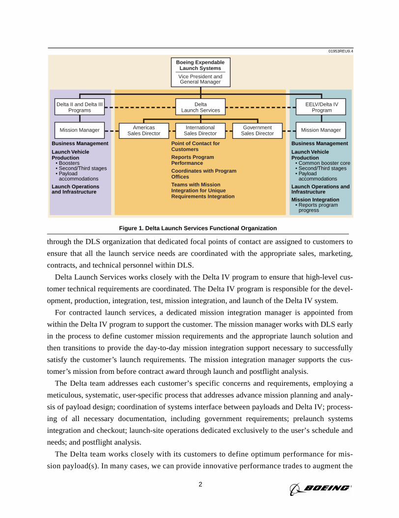
1 Delta Launch Services Functional Organization 2
1-1 Delta/Delta II/Delta III/Delta IV Growth to Meet Customer Needs 1-2
1-2 Performance and Operability of the Delta Family 1-3
1-3 Delta Launch Vehicle Family 1-4
1-4 Delta IV Launch Vehicle Description 1-5
1-5 The RS-68 Engine 1-6
1-6 Delta IV Second-Stage Configurations 1-6
1-7 Delta IV Fairing Configurations 1-9
1-8 Vehicle Axes 1-12
1-9 Launch Vehicle vs Payload Accommodations Coordinate System 1-13
2-1 Typical Two-Stage Mission Profile 2-2
2-2 Delta IV Medium Sequence of Events for a GTO Mission (Eastern Range) 2-3
2-3 Delta IV Medium-Plus (5,2) Sequence of Events for a GTO Mission(Eastern Range) 2-4
2-4 Delta IV-Heavy Sequence of Events for a GTO Mission (Eastern Range) 2-5
2-5 Delta IV Medium-Plus (5,4) Sequence of Events for a LEO Mission(Western Range) 2-6
2-6 Delta IV Heavy Sequence of Events for a LEO Mission (Western Range) 2-7
2-7 Ascending Node GEO Mission Profile 2-7
2-8 Baseline Dual-Manifest Separation Sequence of Events 2-8
2-9a Delta IV-M GTO Apogee Altitude Capability (nmi)—28.5-,27-, and 25-deg Inclinations (Eastern Range) 2-11
2-9b Delta IV-M GTO Apogee Altitude Capability (km)—28.5-,27-, and 25-deg Inclinations (Eastern Range) 2-12
2-10 Delta IV-M GTO Excess∆V Capability—28.9-deg Inclination (Eastern Range)2-13
xii
2-11 Delta IV-M LEO Circular Orbit Capability—45- and 55-deg Inclinations(Eastern Range) 2-14
2-12 Delta IV-M LEO Excess∆V Capability—45- and 55-deg Inclinations(Eastern Range) 2-15
2-13 Delta IV-M LEO Circular Orbit Capability—63.4-deg Inclination andSun-Synchronous (Western Range) 2-16
2-14 Delta IV-M LEO Excess∆V Capability—63.4-deg Inclination andSun-Synchronous (Western Range) 2-17
2-15a Delta IV-M+ (4,2) GTO Apogee Altitude Capability (nmi)—28.5-, 27-, and 25-deg Inclinations (Eastern Range) 2-18
2-15b Delta IV-M+ (4,2) GTO Apogee Altitude Capability (km)—28.5-, 27-, and 25-deg Inclinations (Eastern Range) 2-19
2-16 Delta IV-M+ (4,2) GTO Excess∆V Capability—28.9-deg Inclination(Eastern Range) 2-20
2-17 Delta IV-M+ (4,2) LEO Circular Orbit Capability—45- and 55-degInclinations (Eastern Range) 2-21
2-18 Delta IV-M+ (4,2) LEO Excess∆V Capability—45- and 55-degInclinations (Eastern Range) 2-22
2-19 Delta IV-M+ (4,2) LEO Circular Orbit Capability—63.4-degInclination and Sun-Synchronous (Western Range) 2-23
2-20 Delta IV-M+ (4,2) LEO Excess∆V Capability—63.4-deg Inclination andSun-Synchronous (Western Range) 2-24
2-21a Delta IV-M+ (5,2) GTO Apogee Altitude Capability (nmi)—28.5-, 27-, and 25-deg Inclinations (Eastern Range) 2-25
2-21b Delta IV-M+ (5,2) GTO Apogee Altitude Capability (km)—28.5-, 27-, and 25-deg Inclinations (Eastern Range) 2-26
2-22 Delta IV-M+ (5,2) GTO Excess∆V Capability (km)—28.9-deg Inclination(Eastern Range) 2-27
2-23 Delta IV-M+ (5,2) LEO Circular Orbit Capability—45- and55-deg Inclinations (Eastern Range) 2-28
2-24 Delta IV-M+ (5,2) LEO Excess∆V Capability—45- and 55-degInclinations (Eastern Range) 2-29
xiii
2-25 Delta IV-M+ (5,2) LEO Circular Orbit Capability—63.4-degInclination and Sun-Synchronous (Western Range) 2-30
2-26 Delta IV-M+ (5,2) LEO Excess∆V Capability—63.4-degInclination and Sun-Synchronous (Western Range) 2-31
2-27a Delta IV-M+ (5,4) GTO Apogee Altitude Capability (nmi)—28.5-, 27-, and 25-deg Inclinations (Eastern Range) 2-32
2-27b Delta IV-M+ (5,4) GTO Apogee Altitude Capability (km)—28.5- 27-, and 25-deg Inclinations (Eastern Range) 2-33
2-28 Delta IV-M+ (5,4) GTO Excess∆V Capability—28.9-deg Inclination(Eastern Range) 2-34
2-29 Delta IV-M+ (5,4) LEO Circular Orbit Capability—45- and 55-degInclinations (Eastern Range) 2-35
2-30 Delta IV-M+ (5,4) LEO Excess∆V Capability—45- and 55-degInclinations (Eastern Range) 2-36
2-31 Delta IV-M+ (5,4) LEO Circular Orbit Capability—63.4-degInclination and Sun-Synchronous (Western Range) 2-37
2-32 Delta IV-M+ (5,4) LEO Excess∆V Capability—63.4-degInclination and Sun-Synchronous (Western Range) 2-38
2-33a Delta IV-H Dual-Manifest GTO Apogee Altitude Capability (nmi)—28.5-,27- and 25-deg Inclinations (Eastern Range) 2-39
2-33b Delta IV-H Dual-Manifest GTO Apogee Altitude Capability (km)—28.5-, 27-,and 25-deg Inclinations (Eastern Range) 2-40
2-34 Delta IV-H Dual-Manifest Excess∆V Capability—28.9-deg Inclination(Eastern Range) 2-41
2-35 Delta IV-H Circular Orbit Capability—45- and 55-deg Inclinations(Eastern Range) 2-42
2-36 Delta IV-H LEO Excess∆V Capability—45- and 55-deg Inclinations(Eastern Range) 2-43
2-37 Delta IV-H LEO Circular Orbit Capability—63.4-deg Inclination andSun-Synchronous (Western Range) 2-44
2-38 Delta IV-H LEO Excess∆V Capability—63.4-deg Inclination andSun-Synchronous (Western Range) 2-45
xiv
3-1 Delta IV Fairing Configurations 3-2
3-2 Payload Envelope, 4-m-dia Composite Fairing—1575-4 PAF 3-4
3-3 Payload Envelope, 4-m-dia Composite Fairing 3-4
3-4 Delta IV-Medium-Plus 5-m-dia by 14.3-m-Long Composite FairingPayload Envelope 3-5
3-5 Delta IV Heavy 5-m-dia by 19.1-m Composite Fairing Payload Envelope 3-5
3-6 Allowable Access Door Locations for 4-m-dia by 11.7-m-Long CompositeFairing 3-6
3-7 Allowable Access Door Locations for 5-m-dia by 14.3-m-Long CompositeFairing 3-7
3-8 Allowable Access Door Locations for 5-m-dia by 19.1-m-Long CompositeFairing 3-8
3-9 Delta IV Heavy 5-m-dia by 19.1-m-Long Dual-Manifest Fairing PayloadEnvelope 3-9
3-10 Delta IV Heavy 5-m-dia by 22.4-m-Long Dual-Manifest Fairing PayloadEnvelope 3-10
3-11 Delta IV Heavy 5-m-dia by 19.8-m-Long Metallic Fairing PayloadEnvelope—4394-5 PAF 3-10
4-1 Standard 4-m Composite Fairing and 5-m Composite FairingAir-Conditioning Duct Inlet Configuration 4-1
4-2 5-m Metallic Fairing Payload Air-Distribution System 4-2
4-3 Portable Clean Environmental Shelter (PCES) 4-4
4-4 Delta IV Medium Absolute Pressure Envelope 4-8
4-5 Delta IV Medium-Plus (4,2) Absolute Pressure Envelope 4-8
4-6 Delta IV Medium-Plus (5,2) Absolute Pressure Envelope 4-9
4-7 Delta IV Medium-Plus (5,4) Absolute Pressure Envelope 4-9
4-8 Delta IV Heavy (Composite PLF) Absolute Pressure Envelope 4-10
4-9 Delta IV Heavy (Metallic PLF) Absolute Pressure Envelope 4-10
4-10 Inside Surface Temperature Visible to Payload, 4-m Composite Fairings 4-11
xv
4-11 Inside Surface Temperature Visible to Payload, 5-m Composite Fairings 4-12
4-12 Inside Surface Temperature Visible to Payload, 5-m Metallic Fairings 4-12
4-13 Delta IV Medium Maximum Axial Steady-State Acceleration DuringFirst-Stage Burn vs Second-Stage Payload Weight 4-14
4-14 Delta IV Medium-Plus (4,2) Maximum Axial Steady-State AccelerationDuring First-Stage Burn vs Second-Stage Payload Weight 4-15
4-15 Delta IV Medium-Plus (5,2) Maximum Axial Steady-State AccelerationDuring First-Stage Burn vs Second-Stage Payload Weight 4-15
4-16 Delta IV Medium-Plus (5,4) Maximum Axial Steady-State AccelerationDuring First-Stage Burn vs Second-Stage Payload Weight 4-16
4-17 Delta IV Heavy Maximum Axial Steady-State Acceleration DuringFirst-Stage Burn vs Second-Stage Payload Weight 4-16
4-18 Delta IV Medium Axial Steady-State Acceleration at Second-Stage Cutoff4-17
4-19 Delta IV Medium Plus (4,2) Axial Steady-State Acceleration atSecond-Stage Cutoff 4-17
4-20 Delta IV Medium-Plus (5,2) Axial Steady-State Acceleration atSecond-Stage Cutoff 4-18
4-21 Delta IV Medium-Plus (5,4) Axial Steady-State Acceleration atSecond-Stage Cutoff 4-18
4-22 Delta IV Heavy Axial Steady-State Acceleration at Second-Stage Cutoff 4-19
4-23 Delta IV Medium Design Load Factors for Dynamic Envelope Requirements4-20
4-24 Delta IV Heavy Design Load Factors for Dynamic Envelope Requirements4-21
4-25 Delta IV-M and Delta IV-M+ (4-m Composite Fairing) Internal Payload AcousticsTypical 95 Percentile, 50% Confidence Predictions, 60% Fill Effect Included4-22
4-26 Delta IV-M+ (5-m Composite Fairing) Internal Payload Acoustics Typical95 Percentile, 50% Confidence Predictions, 60% Fill Effect Included 4-23
4-27 Delta IV-Heavy (5-m Composite Fairing) Internal Payload Acoustics Typical95 Percentile, 50% Confidence Predictions, 60% Fill Effect Included 4-23
4-28 Delta IV-Heavy (5-m Metallic Fairing) Internal Payload Acoustics Typical95 Percentile, 50% Confidence Predictions, 60% Fill Effect Included 4-24
xvi
4-29 Maximum Allowable Payload-Induced Shock Levels at Bolted PayloadAttach Fitting Interface 4-25
4-30 Payload Interface Shock Environment—1575-4 Payload Attach Fitting 4-26
4-31 Payload Interface Shock Environment—4394-5 Payload Attach Fitting 4-26
4-32 Payload Interface Shock Environment—1666-4 Payload Attach Fitting 4-27
5-1 Delta IV 4-m Second-Stage Payload Attachment Configurations 5-2
5-2 Delta IV 5-m Second-Stage Payload Attachment Configurations 5-3
5-3 Delta IV 1666-4 PAF 5-4
5-4 1666-4 PAF Separation Spring Assembly and Shear Slot Detail 5-5
5-5 Delta IV 1666-5 PAF 5-6
5-6 Delta IV 1194-4 PAF 5-7
5-7 Delta IV 1194-4 PAF 5-8
5-8 Delta IV 1194-5 PAF 5-9
5-9 Delta IV 937-4 PAF 5-10
5-10 Delta IV 937-5 PAF 5-10
5-11 Delta IV 1664-4 PAF 5-11
5-12 Delta IV 1664-5 PAF 5-11
5-13 Delta IV Evolved Expendable Launch Vehicle 1575-4 PAF 5-12
5-14 Delta IV EELV 1575-4 PAF 5-13
5-15 Delta IV EELV 4394-5 PAF 5-14
5-16 4-m PAF Spacecraft Center of Gravity vs Mass Capability 5-15
5-17 5-m PAF Spacecraft Center of Gravity vs Mass Capability 5-16
6-1 Organizational Interfaces for Commercial Users 6-2
6-2 Astrotech Site Location 6-4
6-3 Astrotech Complex Location 6-4
xvii
6-4 Astrotech Building Locations 6-5
6-5 First-Level Floor Plan, Building 1/1A (PPF), Astrotech 6-6
6-6 Second-Level Floor Plan, Building 1/1A (PPF), Astrotech 6-7
6-7 Building 2 (HPF) Detailed Floor Plan, Astrotech 6-10
6-8 Building 3 Detailed Floor Plan, Astrotech 6-11
6-9 Building 4 Detailed Floor Plan, Astrotech 6-11
6-10 Building 5 Detailed Floor Plan, Astrotech 6-12
6-11 Building 6 Detailed Floor Plan, Astrotech 6-13
6-12 Cape Canaveral Air Station (CCAS) Facilities 6-14
6-13 Electrical-Mechanical Testing Building Floor Plan 6-15
6-14 Payload Encapsulation, Transport, and On-Pad Mate 6-16
6-15 Space Launch Complex 37, CCAS 6-20
6-16 Space Launch Complex 37 Mobile Service Tower (MST) 6-21
6-17 Fixed Platform (Level 8) 6-22
6-18 Adjustable Platform (Levels 9 and 10) 6-22
6-19 Adjustable Platform (Levels 11 and 12) 6-23
6-20 Space Launch Complex 37 Common Support Building (CSB) Sample Layout6-24
6-21 Space Launch Complex 37 Support Equipment Building (SEB) 6-24
6-22 Space Launch Complex 37 Horizontal Integration Facility (HIF) 6-25
6-23 Launch Decision Flow for Commercial Missions—Eastern Range 6-26
6-24 Projected Processing Time Line—Delta IV Medium Launch Vehicle (rev. K)6-30
6-25 Projected Processing Time Line—Delta IV Medium-Plus (4,2) LaunchVehicle (rev. K) 6-31
6-26 Projected Processing Time Line—Delta IV Medium-Plus (5,2) LaunchVehicle (rev. L) 6-32
xviii
6-27 Projected Processing Time Line—Delta IV Medium-Plus (5,4) LaunchVehicle (rev. L) 6-33
6-28 Projected Processing Time Line—Delta IV Heavy Launch Vehicle (rev. L)6-34
6-29 Projected Processing Time Line for Delta IV Heavy Launch VehicleDual-Manifest Missions (Prelim) 6-35
7-1 Launch Base Organization at VAFB for Commercial Launches 7-2
7-2 Vandenberg Air Force Base (VAFB) Facilities 7-3
7-3 Spacecraft Support Area 7-4
7-4 NASA Space Vehicle Laboratory (Building 836) 7-5
7-5 Astrotech Payload Processing Area 7-7
7-6 Astrotech Payload Processing Facility (Building 1032) 7-8
7-7 California Spaceport—Plan View of the Integrated Processing Facility 7-9
7-8 California Spaceport—Integrated Processing Facility Cross-Sectional View7-10
7-9 Spaceport Systems International—Cutaway View of the IntegratedProcessing Facility (Looking South) 7-11
7-10 California Spaceport—Level 89 Technical Support Area 7-18
7-11 California Spaceport—Level 101 Technical Support Area 7-18
7-12 Payload Encapsulation, Transport, and On-Pad Mate—4-m Fairing Example7-19
7-13 Space Launch Complex 6 7-21
7-14 Space Launch Complex 6, VAFB Site Plan 7-22
7-15 Space Launch Complex 6 MST Elevation 7-23
7-16 Platform 8 of Space Launch Complex 6 Mobile Service Tower Plan View 7-24
7-17 Technical Support (Building 384) 7-25
7-18 Delta Operations Center First Floor (Building 392) 7-26
7-19 Delta Operations Center Second Floor (Building 392) 7-27
7-20 Support Equipment Building (SEB) (Building 395) First-Floor Plan 7-28
xix
7-21 Support Equipment Building (SEB) (Building 395) Second-Floor Plan 7-29
7-22 Horizontal Integration Facility (HIF) Site Plan 7-30
7-23 Horizontal Integration Facility (HIF) Floor Plan 7-31
7-24 VAFB Launch Control Center (Building 8510) 7-32
7-25 Launch Control Center (Building 8510) Site Plan 7-32
7-26 Launch Decision Flow for Commercial Missions—Western Range 7-33
7-27 Projected Processing Time Line—Delta IV Medium Launch Vehicle (rev. K)7-36
7-28 Projected Processing Time Line—Delta IV Medium-Plus (4,2) LaunchVehicle (rev. K) 7-37
7-29 Projected Processing Time Line—Delta IV Medium-Plus (5,2) LaunchVehicle (rev. L) 7-38
7-30 Projected Processing Time Line—Delta IV Medium-Plus (5,4) LaunchVehicle (rev. L) 7-39
7-31 Projected Processing Time Line—Delta IV Heavy Launch Vehicle (rev. L)7-40
7-32 Projected Processing Time Line for Delta IV Heavy Launch VehicleDual-Manifest Missions (Preliminary) 7-41
8-1 Mission Integration Process 8-1
8-2 Typical Delta IV Agency Interfaces 8-2
8-3 Typical Document Interfaces 8-3
8-4 Typical Integration Planning Schedule 8-4
/xx
xxi
TABLES
2-1 RIFCA 3-σ Orbit Accuracy—Ten Recent Delta II Missions Through July 19992-46
2-2 Predicted 3-σ Orbit Accuracies for the Delta IV Family of Launch Vehicles 2-47
3-1 Typical Acoustic Blanket Configurations 3-3
4-1 Eastern Range Facility Environments 4-3
4-2 Western Range Facility Environments 4-3
4-3 Delta IV Transmitter Characteristics 4-4
4-4 Cleanliness-Level Definitions 4-5
4-5 Static Envelope Requirements 4-20
4-6 Dynamic Envelope Requirements 4-20
4-7 Spacecraft Acoustic Environment Figure Reference 4-22
4-8 Sinusoidal Vibration Levels 4-24
4-9 Spacecraft Acoustic Test Levels 4-29
4-10 Sinusoidal Vibration Acceptance Test Levels 4-30
4-11 Sinusoidal Vibration Qualification Test Levels 4-30
4-12 Sinusoidal Vibration Protoflight Test Levels 4-30
5-1 Electrical Interface Signal Functions 5-15
6-1 Test Console Items 6-14
6-2 Eastern Range Payload Processing Facilities 6-17
6-3 Payload Processing Facility Matrix 6-18
7-1 Spacecraft Checkout Facility 7-13
7-2 Spacecraft Checkout Area 7-14
7-3 Payload Checkout Cells Capabilities 7-15
7-4 Transfer Tower Area 7-16
xxii
7-5 Fairing Storage and Assembly Area 7-16
7-6 Payload Processing Room (PPR) 6902 7-17
7-7 Payload Processing Room (PPR) 8910 7-17
7-8 Delta IV Payload Encapsulation Facility Requirements 7-20
7-9 Payload Processing Facility Matrix 7-20
8-1 Spacecraft Contractor Data Requirements 8-5
8-2 Boeing Program Documents 8-5
8-3 Required Documents 8-6
8-4 Delta IV Spacecraft Questionnaire 8-10
8-5 Typical Spacecraft Launch-Site Test Plan 8-20
8-6 Data Required for Orbit Parameter Statement 8-21
8-7 Spacecraft Checklist 8-22
xxiii
GLOSSARY
1SLS OB ______________________________ 1st Space Launch Squadron Operations Building
30SW __________________________________________________________ 30th Space Wing
45SW __________________________________________________________ 45th Space Wing
A/C _____________________________________________________________air-conditioning
AASHTO _____________ American Association of State Highway and Transportation Officials
ACS_______________________________________________________ attitude control system
AFB_____________________________________________________________ Air Force Base
AGE __________________________________________________aerospace ground equipment
AKM __________________________________________________________apogee kick motor
ANSI __________________________________________ American National Standards Institute
ASO _______________________________________________ Astrotech Space Operations, LP
AT ________________________________________________________________ access tower
ATP _________________________________________________________ authority to proceed
AWG _______________________________________________________American Wire Gauge
AZ ____________________________________________________________________ azimuth
BAS__________________________________________________________breathing air supply
B/H ________________________________________________________________ blockhouse
B&W____________________________________________________________ black and white
BPS ______________________________________________________________bits per second
CAD ______________________________________________________ computer-aided design
CBC _______________________________________________________ common booster core
CCAM________________________________ contamination and collision avoidance maneuver
CCAS __________________________________________________Cape Canaveral Air Station
CCW __________________________________________________________ counter-clockwise
CFR___________________________________________________Code of Federal Regulations
CG _____________________________________________________________ center of gravity
C/O __________________________________________________________________ checkout
COMSTAC _______________________ Commercial Space Transportation Advisory Committee
xxiv
CPF ____________________________________________________ Centaur processing facility
CRD ___________________________________________________ command receiver decoder
CSB_____________________________________________________ common support building
DBL __________________________________________________ dynamic balance laboratory
DID _________________________________________________________ data item description
DIV-H ___________________________________________________________ Delta IV Heavy
DIV-M_________________________________________________________ Delta IV Medium
DIV-M+____________________________________________________ Delta IV Medium-Plus
DLPS_______________________________________________ Delta launch processing system
DLS_______________________________________________________ Delta Launch Services
DMCO ___________________________________________________ Delta Mission Checkout
DOC _____________________________________________________ Delta Operations Center
DOD ______________________________________________________ Department of Defense
DOF _________________________________________________________ degrees of freedom
DOT _________________________________________________ Department of Transportation
DPC________________________________________________________ dual-payload canister
DPF _____________________________________________________ DSCS Processing Facility
DSCS _____________________________________ Defense Satellite Communications System
DTO ______________________________________________________ detailed test objectives
EAL___________________________________________________________ entry authority list
E&O ___________________________________________________ engineering and operations
E/W __________________________________________________________________ east/west
ECS __________________________________________________ environmental control system
EED______________________________________________________ electro-explosive device
EELV_____________________________________________evolved expendable launch vehicle
EGSE ___________________________________________electrical ground support equipment
EHD ______________________________________________ engineering hardware description
EIRP ______________________________________________effective isotropic radiated power
ELS _____________________________________________________expendable launch system
xxv
ELV ____________________________________________________ expendable launch vehicle
EMC _________________________________________________electromagnetic compatibility
EMI ___________________________________________________electromagnetic interference
EMT __________________________________________________electrical-mechanical testing
EPT __________________________________________________elevating platform transporter
ER _______________________________________________________________ Eastern Range
ESA__________________________________________________________ explosive safe area
ESM _______________________________________________________ erectable service mast
EWR __________________________________________________ Eastern and Western Ranges
FAA________________________________________________Federal Aviation Administration
FDLC _____________________________________________________final design loads cycle
FMA _______________________________________________________ final mission analysis
FO __________________________________________________________________ fiber-optic
FOTS_______________________________________________ fiber-optic transmission system
FPE ________________________________________________________ fixed platform erector
FRR_______________________________________________________ flight readiness review
FS ___________________________________________________________________first stage
FSAA _____________________________________________ fairing storage and assembly area
FTS _____________________________________________________ flight termination system
FUT________________________________________________________ fixed umbilical tower
GC___________________________________________________________ guidance computer
GC&NS________________________________________ guidance control & navigation system
GC3ME _________________ ground command, control, communication, and mission equipment
GEM _______________________________________________________ graphite epoxy motor
GEO __________________________________________________ geosynchronous Earth orbit
GMT _______________________________________________________ Greenwich mean time
GN2 ____________________________________________________________ gaseous nitrogen
GOP ______________________________________________________ ground operations plan
GPS _____________________________________________________ global positioning system
xxvi
GSA ____________________________________________________________ gas storage area
GSE____________________________________________________ ground support equipment
GSFC ________________________________________________ Goddard Space Flight Center
GTO__________________________________________________geosynchronous transfer orbit
H _______________________________________________________________________ heavy
H2 ___________________________________________________________________ hydrogen
H/H ________________________________________________________________ hook height
HB__________________________________________________ Huntington Beach (California)
HEPA ________________________________________________ high-efficiency particulate air
HIF __________________________________________________ horizontal integration facility
HIP _________________________________________________________ hot isostatic pressing
HLV_________________________________________________________heavy launch vehicle
HPF __________________________ hazardous processing facility; hydrogen processing facility
HPTF___________________________________________ hazardous processing testing facility
HVAC _______________________________________ heating, ventilating, and air conditioning
I/F ____________________________________________________________________interface
IACO_____________________________________________________ integration and checkout
IBD ____________________________________________________ inhabited building distance
ICD _____________________________________________________ interface control drawing
IIP _____________________________________________________ instantaneous impact point
IL______________________________________________________________ interline distance
IPA ____________________________________________________________isopropyl alcohol
IPF___________________________________________________ integrated processing facility
IPT________________________________________________________integrated product team
ISP_____________________________________________________________ specific impulse
J-box ______________________________________________________________ junction box
KMI__________________________________________________KSC Management Instruction
KSC_______________________________________________________ Kennedy Space Center
LCC_________________________________________________________launch control center
xxvii
LEA_____________________________________________________ linear explosive assembly
LDXL ____________________________________________________large diameter extra long
LEO_____________________________________________________________ low-Earth orbit
LH2 _____________________________________________________________ liquid hydrogen
LMU ___________________________________________________________ launch mate unit
LO2 ______________________________________________________________ liquid oxygen
LOCC ______________________________________________ launch operations control center
LOP_______________________________________________________ launch operations plan
LPD__________________________________________________ launch processing documents
LPT _____________________________________________________lightning protection tower
LRB_________________________________________________________ liquid rocket booster
LRR______________________________________________________ launch readiness review
LSIM____________________________________________ launch services integration manager
LSRR _________________________________________________ launch site readiness review
LSS __________________________________________________________ launch site support
LSSM _________________________________________________ launch site support manager
LSTP _________________________________________________________ launch site test plan
LT/LSS ___________________________________________launch table/launch support shelter
LV _______________________________________________________________ launch vehicle
LVC_____________________________________________________ launch vehicle contractor
LVCS______________________________________________ launch vehicle coordinate system
LVDC ___________________________________________________launch vehicle data center
M_____________________________________________________________________ medium
MAS ____________________________________________________mobile assembly structure
MCC-1 ________________________________________________Marshall convergent coating
MD _____________________________________________________________mission director
MDA _______________________________________________ McDonnell Douglas Aerospace
MDC __________________________McDonnell Douglas Corporation; Mission Director Center
MECO ________________________________________________________ main-engine cutoff
xxviii
MEOP ____________________________________________ mean expected operating pressure
MIC_____________________________________________________ meets-intent certification
MLV ______________________________________________________ medium launch vehicle
MOI___________________________________________________________ moment of inertia
MPPF _____________________________________________ multi-payload processing facility
MSL _____________________________________________________________ mean sea level
MSPSP ______________________________________ missile system prelaunch safety package
MSR ______________________________________________________mission support request
MST ________________________________________________________ mobile service tower
N/S ________________________________________________________________ north/south
NASA _________________________________ National Aeronautics and Space Administration
NCS_______________________________________________________ nutation control system
NMM _____________________________________________________ national mission model
NPF ____________________________________________________ Navstar processing facility
NUS _____________________________________________________________ no upper stage
NOAA _________________________ National Oceanographic and Atmospheric Administration
OASPL ________________________________________________ overall sound pressure level
OB___________________________________________________________ operations building
OH___________________________________________________________________ overhead
OR________________________________________________________ operations requirement
OSB____________________________________________________operations support building
OVS _____________________________________________________operational voice system
P&C __________________________________________________________ power and control
P/N ________________________________________________________________ part number
PA ______________________________________________________________ payload adapter
PACS_____________________________________ payload accommodations coordinate system
PAF _________________________________________________________payload attach fitting
PAM _______________________________________________________ payload assist module
PCC________________________________________________________ payload checkout cell
xxix
PCES___________________________________________ portable clean environmental shelter
PCM ______________________________________________________ pulse code modulation
PCS ______________________________________________ probability of command shutdown
PDD __________________________________________________ payload database document
PDR_____________________________________________________preliminary design review
PEA____________________________________________________ payload encapsulation area
PEF __________________________________________________payload encapsulation facility
PGOC ___________________________________________ payload ground operations contract
PHE__________________________________________________ propellant handler's ensemble
PHPF__________________________________________ payload hazardous processing facility
PL ____________________________________________________________________ payload
PLF _____________________________________________________________ payload fairing
PMA __________________________________________________preliminary mission analysis
PPF ____________________________________________________ payload processing facility
PPG _______________________________________________________ payload planners guide
PPR _____________________________________________________ payload processing room
PPRD _____________________________________ payload processing requirements document
PRD_______________________________________________ program requirements document
PSM ____________________________________________________ program support manager
PSP ________________________________________________________ program support plan
PSSC ________________________________________________ pad safety supervisor's console
PTR ____________________________________________________ public transportation route
PWU ________________________________________________________ portable weight unit
QD_____________________________________________________________ quick disconnect
RACS _____________________________________________ redundant attitude control system
RCO ________________________________________________________ range control officer
RCS_______________________________________________________ reaction control system
RF ______________________________________________________________ radio frequency
RFA ____________________________________________________radio frequency application
xxx
RFI ___________________________________________________ radio frequency interference
RGA _________________________________________________________ rate gyro assembly
RIFCA______________________________________ redundant inertial flight control assembly
RLCC __________________________range launch control center; remote launch control center
ROC _________________________________________________ range operations commander
ROCC _______________________________________________range operations control center
ROS____________________________________________________ range operations specialist
S&A ______________________________________________________________ safe and arm
S&G _______________________________________________________Sargent and Greenleaf
S/C _________________________________________________________________ spacecraft
SAB____________________________________________________ satellite assembly building
SAEF___________________________________ spacecraft assembly and encapsulation facility
SCAPE _________________________________ self-contained atmosphere protection ensemble
SE ____________________________________________________________support equipment
SEB ___________________________________________________ support equipment building
SECO __________________________________________________ second-stage engine cutoff
SEIP _______________________________________________ standard electric interface panel
SIP_______________________________________________________ standard interface plane
SLC ______________________________________________________ Space Launch Complex
SLC-37 __________________________________________ Space Launch Complex 37 (CCAS)
SLC-6 ____________________________________________ Space Launch Complex 6 (VAFB)
SLS ______________________________________________________ Space Launch Squadron
SMC _____________________________________________ Space and Missile Systems Center
SOB__________________________________________________ squadron operations building
SOP __________________________________________________ standard operating procedure
SPIF _____________________________________________Shuttle payload integration facility
SR&QA_____safety, reliability, and quality assurance; safety requirements and quality assurance
SRM __________________________________________________________ solid rocket motor
SSI_________________________________________________Spaceport Systems International
xxxi
SSME __________________________________________________ Space Shuttle main engine
STD___________________________________________________________________ standard
STG_____________________________________________________________________ stage
STS __________________________________________________ Space Transportation System
SV ________________________________________________________________ space vehicle
SVC______________________________________________________ space vehicle contractor
SVAFB ___________________________________________ South Vandenberg Air Force Base
SVIP __________________________________________________space vehicle interface panel
SW ________________________________________________________________ Space Wing
SW/CC ________________________________________________ Space Wing Control Center
T/M __________________________________________________________________ telemetry
TBD ___________________________________________________________ to be determined
TBR_______________________________________________________________ to be revised
TDRSS _______________________________________ tracking and data relay satellite system
THD _____________________________________________________ total harmonic distortion
TIM __________________________________________________technical interchange meeting
TMR _______________________________________________________ telemetry control rack
TMS ___________________________________________________________ telemetry system
TOPS_________________________________________ transistorized operational phone system
TT&C ____________________________________________ telemetry, tracking, and command
TVC ________________________________________________________ thrust vector control
TWX _____________________________________________________________________telex
UDS ___________________________________________________ universal document system
UPS __________________________________________________ uninterruptable power supply
USAF _____________________________________________________United States Air Force
UV__________________________________________________________________ ultraviolet
VAB____________________________________________________ vertical assembly building
VAC______________________________________________________ volts alternating current
VAFB _________________________________________________ Vandenberg Air Force Base
xxxii
VC____________________________________________________________ visible cleanliness
VCA _______________________________________________________ vehicle checkout area
VCF______________________________________________________ vehicle checkout facility
VCR _________________________________________________________vehicle control rack
VDC _________________________________________________________ volts direct current
VDL ____________________________________________________________voice direct line
VIM______________________________________________ vehicle information memorandum
VLC ______________________________________________________ verification loads cycle
VM ______________________________________________________________ video monitor
VOS ____________________________________________________________vehicle on stand
VPF ____________________________________________________ vertical processing facility
VRR _____________________________________________________ vehicle readiness review
W/D_________________________________________________________________ walkdown
W/O___________________________________________________________________ without
WR _____________________________________________________________ Western Range
1
INTRODUCTION
This Delta IV Payload Planners Guide (PPG) is provided by The Boeing Company to familiar-
ize customers with Delta IV launch services. Delta background and heritage, Delta IV launch
vehicle configurations, their performance capabilities, and correlated launch services are
described in this guide. Payload interfaces and the environments that the spacecraft will experi-
ence during launch are also defined. Facilities, operations, and payload processing procedures are
described, as well as the documentation, integration, and procedural requirements associated with
preparing for and conducting a launch.
The Delta IV configurations described herein are the latest evolution of our reliable Delta fam-
ily, developed to provide the international user community with efficient, low-cost access to space.
In four decades of use, Delta launch vehicle success stems from its evolutionary design, which has
been steadily upgraded to meet the needs of the user community while maintaining high reliability.
A new launch complex, Space Launch Complex 37 (SLC-37), is being constructed at Cape
Canaveral Air Station (CCAS) in Florida to support our commercial and government customers.
The Delta IV will be launched from SLC-37 for geosynchronous transfer orbit (GTO) missions as
well as missions requiring low- and medium-inclination orbits. Boeing will provide launches
from SLC-6 at South Vandenberg Air Force Base, California, for high-inclination missions. Spe-
cific vehicle performance data are presented inSection 2.
As a commercial launch services provider, Boeing acts as the coordinating agent for the user in
interfacing with the United States Air Force (USAF), the Federal Aviation Administration (FAA),
the designated payload processing facility, and any other relevant agency when other commercial
or government facilities are engaged for spacecraft processing. Commercialization agreements
with the USAF provide Boeing the use of launch facilities and services in support of Delta IV
launch services.
During the first quarter of 1999, the transition of McDonnell Douglas Commercial Delta, Inc.,
to Delta Launch Services, Inc., was completed. As part of this reorganization, we have designed
Delta Launch Services (DLS) to improve customer satisfaction, provide a single point of contact,
and increase responsiveness. Delta Launch Services offers full-service launch solutions using the
Delta II, Delta III, and Delta IV family of launch vehicles. The customer is supported by an inte-
grated product team (IPT)-based organization consisting of highly knowledgeable technical and
managerial personnel who are dedicated to open communication and responsive to all customer
needs (Figure 1).
Delta Launch Services has the ultimate responsibility, authority, and accountability for all Delta
customer opportunities. This includes developing launch solutions to meet customer needs as well
as providing customers with a launch service agreement for the selected launch services. It is
2
through the DLS organization that dedicated focal points of contact are assigned to customers to
ensure that all the launch service needs are coordinated with the appropriate sales, marketing,
contracts, and technical personnel within DLS.
Delta Launch Services works closely with the Delta IV program to ensure that high-level cus-
tomer technical requirements are coordinated. The Delta IV program is responsible for the devel-
opment, production, integration, test, mission integration, and launch of the Delta IV system.
For contracted launch services, a dedicated mission integration manager is appointed from
within the Delta IV program to support the customer. The mission manager works with DLS early
in the process to define customer mission requirements and the appropriate launch solution and
then transitions to provide the day-to-day mission integration support necessary to successfully
satisfy the customer’s launch requirements. The mission integration manager supports the cus-
tomer’s mission from before contract award through launch and postflight analysis.
The Delta team addresses each customer’s specific concerns and requirements, employing a
meticulous, systematic, user-specific process that addresses advance mission planning and analy-
sis of payload design; coordination of systems interface between payloads and Delta IV; process-
ing of all necessary documentation, including government requirements; prelaunch systems
integration and checkout; launch-site operations dedicated exclusively to the user’s schedule and
needs; and postflight analysis.
The Delta team works closely with its customers to define optimum performance for mis-
sion payload(s). In many cases, we can provide innovative performance trades to augment the
01953REU9.4
Boeing Expendable Launch Systems
Point of Contact forCustomers
Reports ProgramPerformance
Coordinates with ProgramOffices
Teams with MissionIntegration for UniqueRequirements Integration
Business Management
Launch Vehicle Production
• Common booster core• Second/Third stages• Payload • accommodations
Launch Operations and Infrastructure
Mission Integration• Reports program
progress
Business Management
Launch Vehicle Production
• Boosters• Second/Third stages• Payload • accommodations
Launch Operations and Infrastructure
Vice President andGeneral Manager
Mission Manager Mission ManagerInternationalSales Director
AmericasSales Director
GovernmentSales Director
DeltaLaunch Services
Delta II and Delta IIIPrograms
EELV/Delta IVProgram
Figure 1. Delta Launch Services Functional Organization
3
performance shown inSection 2. Our Delta team also has extensive experience in supporting
customers around the world. This demonstrated capability to use the flexibility of the Delta
launch vehicle and design team, together with our experience in supporting customers world-
wide, makes Delta the ideal choice as a launch services provider.
Delta IV offers dedicated as well as dual-manifest launch services, the benefits of a launch
team committed to each user’s payload, and a mission profile and launch window designed for
individual mission orbits. Delta’s manifesting, whether dedicated or dual-manifest, provides
exceptional cost control and overall efficiency, simplified integration processes, on-time launch
assurance, and efficient flight operations and control. Further, our dual-manifest system provides
the payload community autonomy similar to a dedicated launch with price economies of a shared
launch. Coupled with these launch service attributes is the Boeing commitment to excellence and
proven dependability which, for more than three decades, has given our customers the highest
assurance of a successful launch campaign.
1-1
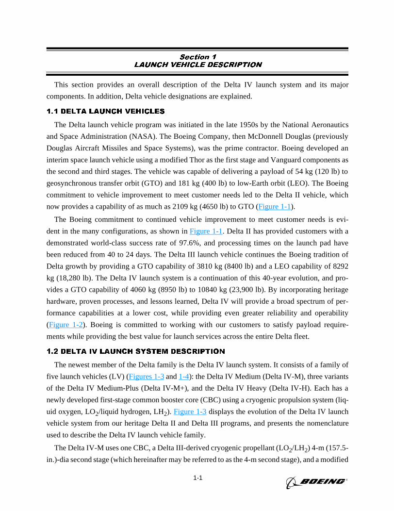
Section 1
LAUNCH VEHICLE DESCRIPTION
This section provides an overall description of the Delta IV launch system and its major
components. In addition, Delta vehicle designations are explained.
1.1 DELTA LAUNCH VEHICLES
The Delta launch vehicle program was initiated in the late 1950s by the National Aeronautics
and Space Administration (NASA). The Boeing Company, then McDonnell Douglas (previously
Douglas Aircraft Missiles and Space Systems), was the prime contractor. Boeing developed an
interim space launch vehicle using a modified Thor as the first stage and Vanguard components as
the second and third stages. The vehicle was capable of delivering a payload of 54 kg (120 lb) to
geosynchronous transfer orbit (GTO) and 181 kg (400 lb) to low-Earth orbit (LEO). The Boeing
commitment to vehicle improvement to meet customer needs led to the Delta II vehicle, which
now provides a capability of as much as 2109 kg (4650 lb) to GTO (Figure 1-1).
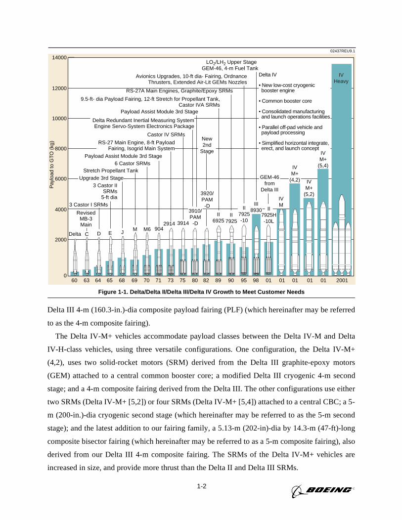
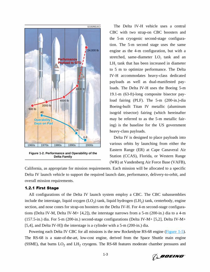
The Boeing commitment to continued vehicle improvement to meet customer needs is evi-
dent in the many configurations, as shown inFigure 1-1. Delta II has provided customers with a
demonstrated world-class success rate of 97.6%, and processing times on the launch pad have
been reduced from 40 to 24 days. The Delta III launch vehicle continues the Boeing tradition of
Delta growth by providing a GTO capability of 3810 kg (8400 lb) and a LEO capability of 8292
kg (18,280 lb). The Delta IV launch system is a continuation of this 40-year evolution, and pro-
vides a GTO capability of 4060 kg (8950 lb) to 10840 kg (23,900 lb). By incorporating heritage
hardware, proven processes, and lessons learned, Delta IV will provide a broad spectrum of per-
formance capabilities at a lower cost, while providing even greater reliability and operability
(Figure 1-2). Boeing is committed to working with our customers to satisfy payload require-
ments while providing the best value for launch services across the entire Delta fleet.
1.2 DELTA IV LAUNCH SYSTEM DESCRIPTION
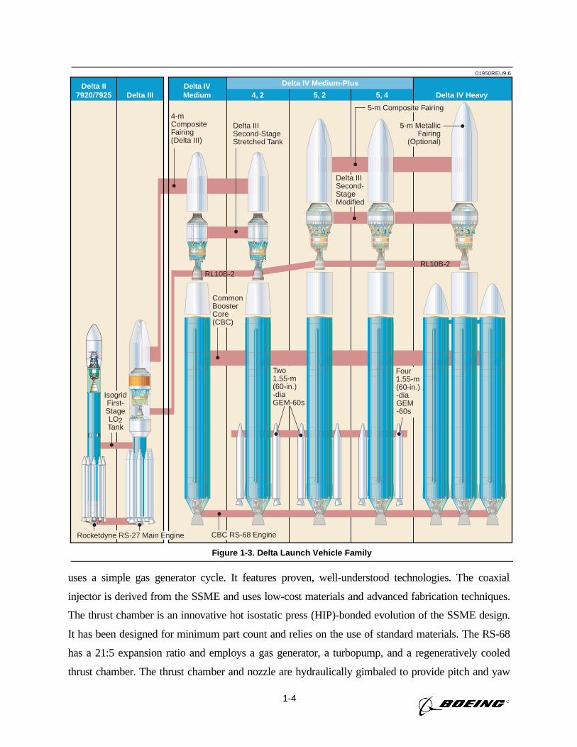
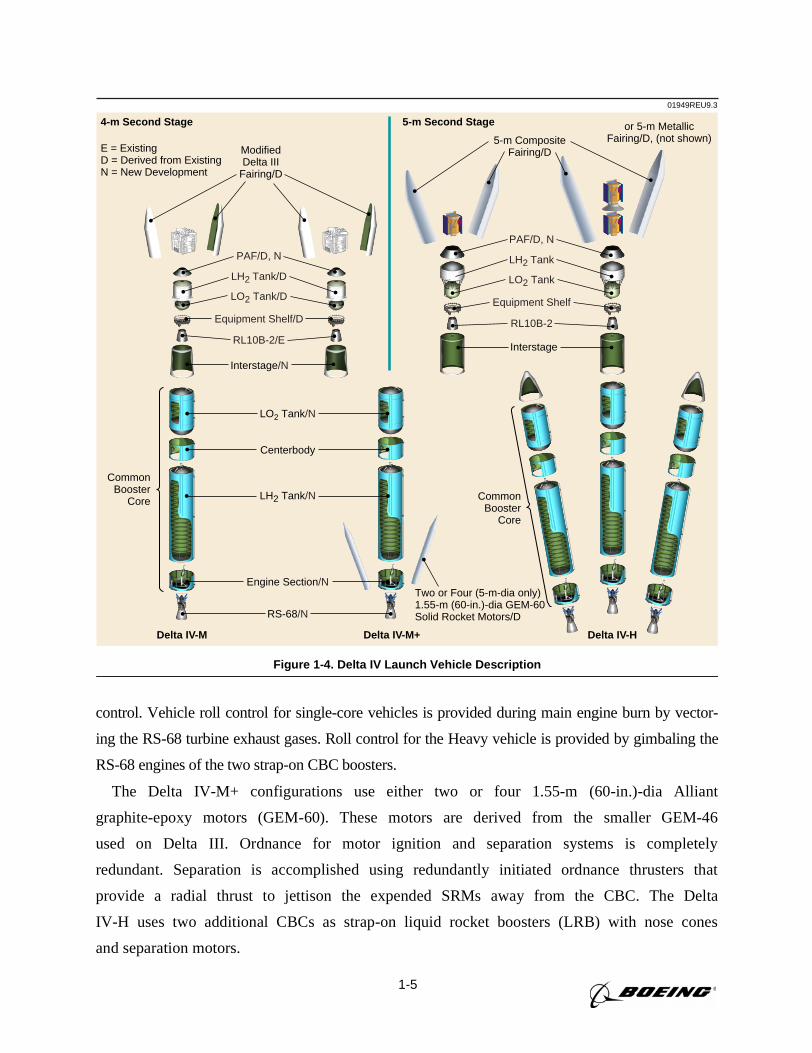
The newest member of the Delta family is the Delta IV launch system. It consists of a family of
five launch vehicles (LV) (Figures 1-3and1-4): the Delta IV Medium (Delta IV-M), three variants
of the Delta IV Medium-Plus (Delta IV-M+), and the Delta IV Heavy (Delta IV-H). Each has a
newly developed first-stage common booster core (CBC) using a cryogenic propulsion system (liq-
uid oxygen, LO2/liquid hydrogen, LH2). Figure 1-3displays the evolution of the Delta IV launch
vehicle system from our heritage Delta II and Delta III programs, and presents the nomenclature
used to describe the Delta IV launch vehicle family.
The Delta IV-M uses one CBC, a Delta III-derived cryogenic propellant (LO2/LH2) 4-m (157.5-
in.)-dia second stage (which hereinafter may be referred to as the 4-m second stage), and a modified
1-2
Delta III 4-m (160.3-in.)-dia composite payload fairing (PLF) (which hereinafter may be referred
to as the 4-m composite fairing).
The Delta IV-M+ vehicles accommodate payload classes between the Delta IV-M and Delta
IV-H-class vehicles, using three versatile configurations. One configuration, the Delta IV-M+
(4,2), uses two solid-rocket motors (SRM) derived from the Delta III graphite-epoxy motors
(GEM) attached to a central common booster core; a modified Delta III cryogenic 4-m second
stage; and a 4-m composite fairing derived from the Delta III. The other configurations use either
two SRMs (Delta IV-M+ [5,2]) or four SRMs (Delta IV-M+ [5,4]) attached to a central CBC; a 5-
m (200-in.)-dia cryogenic second stage (which hereinafter may be referred to as the 5-m second
stage); and the latest addition to our fairing family, a 5.13-m (202-in)-dia by 14.3-m (47-ft)-long
composite bisector fairing (which hereinafter may be referred to as a 5-m composite fairing), also
derived from our Delta III 4-m composite fairing. The SRMs of the Delta IV-M+ vehicles are
increased in size, and provide more thrust than the Delta II and Delta III SRMs.
02437REU9.1
0
2000
4000
6000
8000
Pay
load
to G
TO (
kg)
10000
12000
14000
RS-27A Main Engines, Graphite/Epoxy SRMs
Payload Assist Module 3rd Stage
6 Castor SRMs
3 Castor I SRMs
Stretch Propellant Tank
Payload Assist Module 3rd Stage
9.5-ft- dia Payload Fairing, 12-ft Stretch for Propellant Tank, Castor IVA SRMs
Castor IV SRMsNew 2nd
Stage
RevisedMB-3 Main
Delta Redundant Inertial Measuring SystemEngine Servo-System Electronics Package
RS-27 Main Engine, 8-ft PayloadFairing, Isogrid Main System
3 Castor II SRMs
5-ft dia
60
Delta
63
C
90
II7925
9589
II6925
82807573
2914
71
904
70
M6
69
M
68
J
65
E
64
D
98
LO2/LH2 Upper Stage GEM-46, 4-m Fuel Tank
01
IVM
2001
IVHeavy
01 01
IVM+
(5,2)
0101
Avionics Upgrades, 10-ft dia- Fairing, Ordnance Thrusters, Extended Air-Lit GEMs Nozzles
Delta IV
• New low-cost cryogenicbooster engine
• Common booster core
• Consolidated manufacturingand launch operations facilities
• Parallel off-pad vehicle andpayload processing
• Simplified horizontal integrate,erect, and launch concept
IVM+
(5,4)IVM+
(4,2)GEM-46from
Delta III
III8930II
7925-10
3920/PAM
-D3910/PAM
-D3914
Upgrade 3rd Stage
II7925H-10L
Figure 1-1. Delta/Delta II/Delta III/Delta IV Growth to Meet Customer Needs
1-3
The Delta IV-H vehicle uses a central
CBC with two strap-on CBC boosters and
the 5-m cryogenic second-stage configura-
tion. The 5-m second stage uses the same
engine as the 4-m configuration, but with a
stretched, same-diameter LO2 tank and an
LH2 tank that has been increased in diameter
to 5 m to optimize performance. The Delta
IV-H accommodates heavy-class dedicated
payloads as well as dual-manifested pay-
loads. The Delta IV-H uses the Boeing 5-m
19.1-m (63-ft)-long composite bisector pay-
load fairing (PLF). The 5-m (200-in.)-dia
Boeing-built Titan IV metallic (aluminum
isogrid trisector) fairing (which hereinafter
may be referred to as the 5-m metallic fair-
ing) is the baseline for the US government
heavy-class payloads.
Delta IV is designed to place payloads into
various orbits by launching from either the
Eastern Range (ER) at Cape Canaveral Air
Station (CCAS), Florida, or Western Range
(WR) at Vandenberg Air Force Base (VAFB),
California, as appropriate for mission requirements. Each mission will be allocated to a specific
Delta IV launch vehicle to support the required launch date, performance, delivery-to-orbit, and
overall mission requirements.
1.2.1 First Stage
All configurations of the Delta IV launch system employ a CBC. The CBC subassemblies
include the interstage, liquid oxygen (LO2) tank, liquid hydrogen (LH2) tank, centerbody, engine
section, and nose cones for strap-on boosters on the Delta IV-H. For 4-m second-stage configura-
tions (Delta IV-M, Delta IV-M+ [4,2]), the interstage narrows from a 5-m (200-in.) dia to a 4-m
(157.5-in.) dia. For 5-m (200-in.) second-stage configurations (Delta IV-M+ [5,2], Delta IV-M+
[5,4], and Delta IV-H]) the interstage is a cylinder with a 5-m (200-in.) dia.
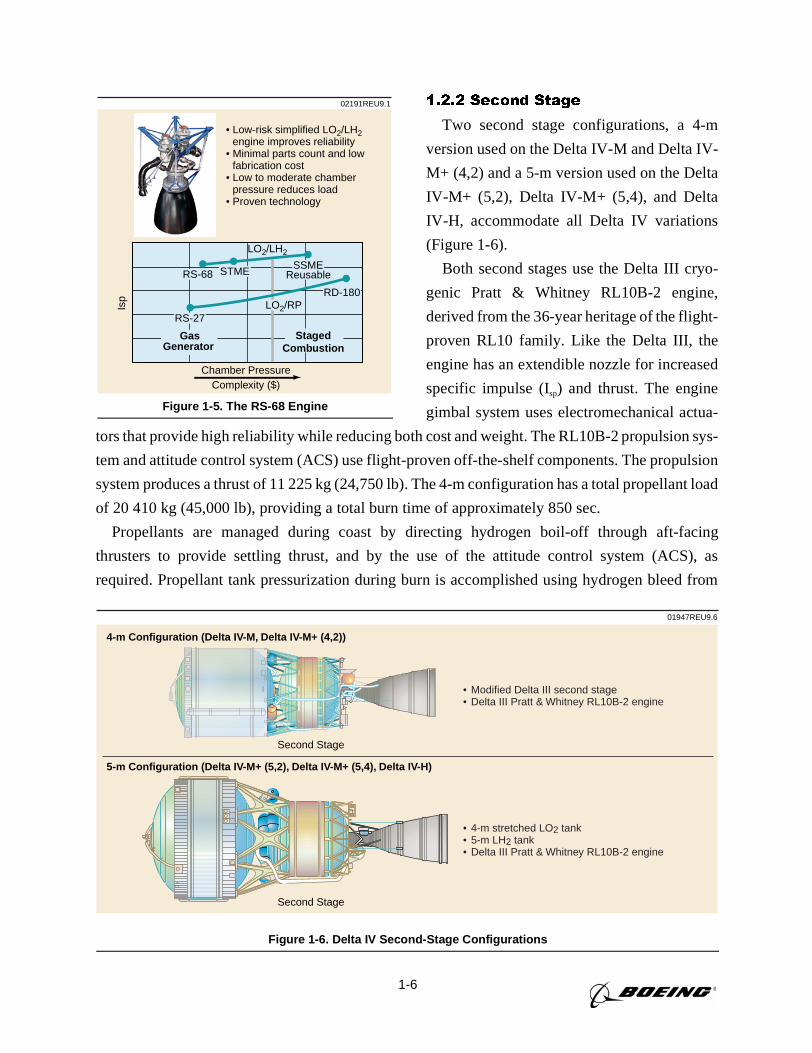
Powering each Delta IV CBC for all missions is the new Rocketdyne RS-68 engine (Figure 1-5).
The RS-68 is a state-of-the-art, low-cost engine, derived from the Space Shuttle main engine
(SSME), that burns LO2 and LH2 cryogens. The RS-68 features moderate chamber pressures and
02192REU9.3
PerformancePayload to GTOPerformancePayload to GTO
1960s 1970s 1980s 1990s 2000s
500 lb2000 lb
4000 lb
8400 lb
24,000 lb
8400 lb
40
6-8
24
OperabilityDays on PadOperabilityDays on Pad
Figure 1-2. Performance and Operability of theDelta Family
1-4
uses a simple gas generator cycle. It features proven, well-understood technologies. The coaxial
injector is derived from the SSME and uses low-cost materials and advanced fabrication techniques.
The thrust chamber is an innovative hot isostatic press (HIP)-bonded evolution of the SSME design.
It has been designed for minimum part count and relies on the use of standard materials. The RS-68
has a 21:5 expansion ratio and employs a gas generator, a turbopump, and a regeneratively cooled
thrust chamber. The thrust chamber and nozzle are hydraulically gimbaled to provide pitch and yaw
5-m Composite Fairing
5-m Metallic Fairing
(Optional)
Delta IV Medium-Plus
5, 24, 2Delta IVMediumDelta III
Delta II7920/7925 5, 4 Delta IV Heavy
4-mCompositeFairing(Delta III)
Delta IIISecond-StageStretched Tank
Delta IIISecond-StageModified
RL10B-2RL10B-2
01950REU9.6
IsogridFirst-StageLO2Tank
CBC RS-68 Engine
Two1.55-m(60-in.)-diaGEM-60s
Four1.55-m(60-in.)-diaGEM-60s
CommonBoosterCore(CBC)
Rocketdyne RS-27 Main Engine
Figure 1-3. Delta Launch Vehicle Family
1-5
control. Vehicle roll control for single-core vehicles is provided during main engine burn by vector-
ing the RS-68 turbine exhaust gases. Roll control for the Heavy vehicle is provided by gimbaling the
RS-68 engines of the two strap-on CBC boosters.
The Delta IV-M+ configurations use either two or four 1.55-m (60-in.)-dia Alliant
graphite-epoxy motors (GEM-60). These motors are derived from the smaller GEM-46
used on Delta III. Ordnance for motor ignition and separation systems is completely
redundant. Separation is accomplished using redundantly initiated ordnance thrusters that
provide a radial thrust to jettison the expended SRMs away from the CBC. The Delta
IV-H uses two additional CBCs as strap-on liquid rocket boosters (LRB) with nose cones
and separation motors.
01949REU9.3
Delta IV-M Delta IV-M+ Delta IV-H
CommonBooster
Core Common Booster
Core
LH2 Tank/N
Centerbody
LO2 Tank/N
Interstage/N
Two or Four (5-m-dia only)1.55-m (60-in.)-dia GEM-60Solid Rocket Motors/D
E = ExistingD = Derived from ExistingN = New Development
Interstage
Engine Section/N
RS-68/N
4-m Second Stage
ModifiedDelta III
Fairing/D
5-m CompositeFairing/D
or 5-m MetallicFairing/D, (not shown)
5-m Second Stage
PAF/D, N
LH2 Tank/D
LO2 Tank/D
Equipment Shelf/D
RL10B-2/E
PAF/D, N
LH2 Tank
LO2 Tank
Equipment Shelf
RL10B-2
Figure 1-4. Delta IV Launch Vehicle Description
1-6
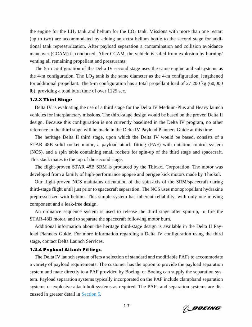
1.2.2 Second Stage
Two second stage configurations, a 4-m
version used on the Delta IV-M and Delta IV-
M+ (4,2) and a 5-m version used on the Delta
IV-M+ (5,2), Delta IV-M+ (5,4), and Delta
IV-H, accommodate all Delta IV variations
(Figure 1-6).
Both second stages use the Delta III cryo-
genic Pratt & Whitney RL10B-2 engine,
derived from the 36-year heritage of the flight-
proven RL10 family. Like the Delta III, the
engine has an extendible nozzle for increased
specific impulse (Isp) and thrust. The engine
gimbal system uses electromechanical actua-
tors that provide high reliability while reducing both cost and weight. The RL10B-2 propulsion sys-
tem and attitude control system (ACS) use flight-proven off-the-shelf components. The propulsion
system produces a thrust of 11 225 kg (24,750 lb). The 4-m configuration has a total propellant load
of 20 410 kg (45,000 lb), providing a total burn time of approximately 850 sec.
Propellants are managed during coast by directing hydrogen boil-off through aft-facing
thrusters to provide settling thrust, and by the use of the attitude control system (ACS), as
required. Propellant tank pressurization during burn is accomplished using hydrogen bleed from
02191REU9.1
• Low-risk simplified LO2/LH2 engine improves reliability
• Minimal parts count and low fabrication cost
• Low to moderate chamber pressure reduces load
• Proven technology
LO2/LH2
Chamber Pressure
Isp RD-180
RS-27
SSMESTMERS-68
Complexity ($)
StagedCombustion
GasGenerator
Reusable
LO2/RP
Figure 1-5. The RS-68 Engine
01947REU9.6
Second Stage
4-m Configuration (Delta IV-M, Delta IV-M+ (4,2))
5-m Configuration (Delta IV-M+ (5,2), Delta IV-M+ (5,4), Delta IV-H)
Second Stage
• Modified Delta III second stage• Delta III Pratt & Whitney RL10B-2 engine
• 4-m stretched LO2 tank• 5-m LH2 tank• Delta III Pratt & Whitney RL10B-2 engine
Figure 1-6. Delta IV Second-Stage Configurations
1-7
the engine for the LH2 tank and helium for the LO2 tank. Missions with more than one restart
(up to two) are accommodated by adding an extra helium bottle to the second stage for addi-
tional tank repressurization. After payload separation a contamination and collision avoidance
maneuver (CCAM) is conducted. After CCAM, the vehicle is safed from explosion by burning/
venting all remaining propellant and pressurants.
The 5-m configuration of the Delta IV second stage uses the same engine and subsystems as
the 4-m configuration. The LO2 tank is the same diameter as the 4-m configuration, lengthened
for additional propellant. The 5-m configuration has a total propellant load of 27 200 kg (60,000
lb), providing a total burn time of over 1125 sec.
1.2.3 Third Stage
Delta IV is evaluating the use of a third stage for the Delta IV Medium-Plus and Heavy launch
vehicles for interplanetary missions. The third-stage design would be based on the proven Delta II
design. Because this configuration is not currently baselined in the Delta IV program, no other
reference to the third stage will be made in the Delta IV Payload Planners Guide at this time.
The heritage Delta II third stage, upon which the Delta IV would be based, consists of a
STAR 48B solid rocket motor, a payload attach fitting (PAF) with nutation control system
(NCS), and a spin table containing small rockets for spin-up of the third stage and spacecraft.
This stack mates to the top of the second stage.
The flight-proven STAR 48B SRM is produced by the Thiokol Corporation. The motor was
developed from a family of high-performance apogee and perigee kick motors made by Thiokol.
Our flight-proven NCS maintains orientation of the spin-axis of the SRM/spacecraft during
third-stage flight until just prior to spacecraft separation. The NCS uses monopropellant hydrazine
prepressurized with helium. This simple system has inherent reliability, with only one moving
component and a leak-free design.
An ordnance sequence system is used to release the third stage after spin-up, to fire the
STAR-48B motor, and to separate the spacecraft following motor burn.
Additional information about the heritage third-stage design is available in the Delta II Pay-
load Planners Guide. For more information regarding a Delta IV configuration using the third
stage, contact Delta Launch Services.
1.2.4 Payload Attach Fittings
The Delta IV launch system offers a selection of standard and modifiable PAFs to accommodate
a variety of payload requirements. The customer has the option to provide the payload separation
system and mate directly to a PAF provided by Boeing, or Boeing can supply the separation sys-
tem. Payload separation systems typically incorporated on the PAF include clampband separation
systems or explosive attach-bolt systems as required. The PAFs and separation systems are dis-
cussed in greater detail inSection 5.
1-8
In addition, Boeing has extensive experience designing and building satellite dispensing systems
for multiple satellite launches. Our dispensers have a 100% success rate. For more information
regarding satellite dispensing systems, please contact Delta Launch Services.
1.2.5 Payload Fairings
The Delta IV launch system offers the PLFs shown inFigure 1-7. These fairings provide pro-
tection to the satellite vehicle from the aerodynamic, acoustic, and thermal environments through
the launch and ascent phases of flight. The 4-m fairing is a stretched Delta III 4-m composite
bisector fairing.
The 5-m composite fairing is based on the Delta III 4-m composite fairing and comes in two
standard lengths: 14.3 m (47 ft) and 19.1 m (62.7 ft). The dual-manifest fairing consists of two
sections, a 5-m composite bisector fairing and a lower 5-m composite dual-payload canister (DPC).
The dual-manifest configurations come in two lengths: 19.1-m (62.7 ft)-long, and 22.4-m (73.5-ft)-
long. This construction is described in greater detail in Section 1.2.6.
The 5-m metallic trisector fairing is a modified version of the Boeing-designed, -manufactured,
and flight-proven Titan IV aluminum isogrid fairing.
All PLFs are configured for off-pad payload encapsulation (seeSections 6.3and 7.3) to
enhance payload safety and security, and to minimize on-pad time. All fairings incorporate inte-
rior acoustic absorption materials as well as flight-proven contamination-free separation joints.
Boeing provides mission-specific modifications to the fairings as required by the customer. These
include access doors, additional acoustic materials, and radio frequency (RF) windows. Fairings
are discussed in greater detail inSection 3.
1.2.6 Dual-Manifest Capability
The Delta IV launch system offers the capability of dual-manifesting payloads on our
Delta IV-H launch vehicle (seeSection 2for dual-manifest payload capability), beginning in
2002. The Delta IV-H dual-manifest system provides payload autonomy similar to a dedi-
cated launch with the price economy of a shared launch, or the capability of launching
multiple payloads in a single launch at a significant cost reduction compared to a dedi-
cated launch. Our Delta IV-H dual-manifest approach has the capability to launch two
spacecraft totaling up to 10 800 kg (23,900 lb) to our standard 27-deg GTO orbit using a
5-m composite fairing with a total length of 22.4 m (73.5 ft).
Our 5-m-dia 19.1-m (62.7-ft)-long Delta IV-H dual-manifest system consists of a 12.3-m
(40.3-ft)-long composite fairing and a 6.8-m (22.4-ft)-long DPC. Our 5-m-dia 22.4-m (73.5-ft)-
long Delta IV-H dual-manifest system consists of a 14.3-m (47-ft)-long composite bisector
fairing and an 8.1-m (26.5-ft)-long DPC. The dual-manifest system consists of two indepen-
dent payload bays, similar in volume, which are vented separately. Both spacecraft are

1-9
02053REU9.5
mm(in.)
• 5.13-m (202-in.)-dia composite fairing• Graphite-epoxy/foam core composite sandwich structure
• 5.13-m (202-in.)-dia composite fairing and composite dual-payload canister• Graphite-epoxy/foam core composite sandwich structure
• 5.13-m (202-in.)-dia composite fairing and composite dual-payload canister• Graphite-epoxy/foam core composite sandwich structure
• 5.13-m (202-in.)-dia composite fairing• Graphite-epoxy/foam core composite sandwich structure
• 4-m (160.3-in.)-dia compositefairing with extended cylindricalsection
• Graphite-epoxy/foam corecomposite sandwich structure
19.1-m (62.7-ft)-Long FairingDelta IV-H
11.7-m (38.5-ft)-Long FairingDelta IV-M and Delta IV-M+ (4,2)
14.3-m (47-ft )-Long FairingDelta IV-M+ (5,2) and Delta IV-M+ (5,4)
19.1-m (62.7-ft)-Long Fairingand Dual-Payload CanisterDelta IV-H Dual Manifest
22.4-m (73.5-ft)-Long Fairingand Dual-Payload CanisterDelta IV-H Dual Manifest
14,338(564.5)
11,751(462.6)
6931(272.9)
8315(327.4)
5131(202.0)
dia
4070(160.3)
dia
• 5-m (200-in.)-dia modifiedTitan IV fairing built by Boeing
• Aluminum isogrid structure
19.8-m (65-ft)-Long FairingDelta IV-H (GovernmentBaseline)
7665 (301.8)
Base (240.0)Cylinder
6096 (238.3)
Nose
6053
19,814(780.1)
5080(200.0)
dia
19,098(751.9)
13075(514.8)
5131(202.0)
dia
22,409(882.2)
16386(645.1)
8071(317.8)
5131(202.0)
dia
19,098(751.9)
13075(514.8)
5131(202.0)
dia
6821(268.6)
Payload Encapsulation Plane
Payload Encapsulation Plane
Payload Encapsulation Plane
Payload Encapsulation Plane
Payload Encapsulation Plane
Payload Encapsulation Plane
Figure 1-7. Delta IV Fairing Configurations
1-10
mounted within these bays to standard Delta IV PAF separation interfaces, dependent on
spacecraft needs. For dual-manifest launches, two standard fairing access doors are provided in
the cylindrical section of each payload bay. As with the Delta IV single-manifest composite
fairing, existing acoustic blankets are provided from the aft end of the fairing to the nose
cone.
For fairing separation, the same noncontaminating thrusting joint system designed and patented
by Boeing (presented inSection 3.2) is used for bisector separation of the composite fairing. For
the lower payload bay, a circumferential sure-sep system (patented by Boeing) with spring actua-
tors is used to deploy the DPC over the spacecraft.
The dual-manifest capability is currently being evaluated for use on other Delta IV vehicle con-
figurations. For further details on the Delta IV Heavy dual-manifest system, as well as dual-mani-
fest launches on other Delta IV vehicles, contact Delta Launch Services.
1.2.7 Avionics and Flight Software
The Delta IV launch system uses a modified advanced Delta III avionics system with a fully fault-
tolerant avionics suite, including a redundant inertial flight control assembly (RIFCA) and auto-
mated launch operations processing using a modified advanced launch control system.
The RIFCA, supplied by AlliedSignal, uses six RL20 ring laser gyros and six QA3000 acceler-
ometers to provide redundant three-axis attitude and velocity data. In addition to RIFCA, both the
first- and second-stage avionics include interface and control electronics to support vehicle control
and sequencing; a power and control box to support power distribution; an ordnance box to issue
ordnance commands; and a pulse code modulation (PCM) telemetry (T/M) system with switchable
formats that provide real-time vehicle system performance data to ground stations either directly or
through the tracking and data relay satellite system (TDRSS). TDRSS is used to relay post-boost
telemetry information when ground coverage is not available, and provides improved mission flex-
ibility with global telemetry coverage. A C-band (beacon) transponder is provided for vehicle track-
ing to support the flight termination system (FTS).
The flight software comprises a standard flight program and a mission-constants database specifi-
cally designed to meet each customer’s mission requirements. Mission requirements are implemented
by configuring the mission-constants database, which will be designed to fly the mission trajectory
and to separate the satellite at the proper attitude and time. The mission-constants database is validated
during the hardware/software functional validation tests, the systems integration tests, and the final
software validation test.
The RIFCA contains the control logic that processes rate and accelerometer data to form the
proportional and discrete control output commands needed to drive the control actuators and cold
gas jet control thrusters.
1-11
Position and velocity data are explicitly computed to derive guidance steering commands.
Early in flight, a load-relief mode turns the vehicle into the wind to reduce angle of attack, struc-
tural loads, and control effort. After dynamic pressure decay, the guidance system corrects trajec-
tory dispersions caused by load relief and vehicle performance variations and directs the vehicle
to the nominal end-of-stage orbit. Payload separation in the desired transfer orbit is accomplished
by applying time adjustments to the nominal engine start/stop sequence, in addition to the
required guidance steering commands.
1.3 DELTA IV VEHICLE COORDINATE SYSTEM
The axes of the vehicle are defined inFigure 1-8. An overhead view shows the vehicle orienta-
tion to the launch pad. The launch vehicle coordinate system is shown with the vehicle pitch, roll
and yaw. The vehicle centerline is the longitudinal axis of the vehicle. Axis II (+Z) is on the
downrange side of the vehicle, and axis IV (-Z) is on the up-range side. The vehicle pitches about
axes I (+Y) and III (-Y). Positive pitch rotates the nose of the vehicle up, toward axis IV. The
vehicle yaws about axes II and IV. Positive yaw rotates the nose to the right, toward axis I. The
vehicle rolls about the centerline. Positive roll is clockwise rotation, looking forward from the aft
end of the vehicle (i.e., from axis I toward axis II).
1.3.1 Orientation
Two distinct coordinate systems are of interest to the spacecraft customer. First is the launch
vehicle coordinate system, which has already been discussed. The second system is the payload
accommodations (PLA) coordinate system.Figure 1-9shows the orientation of the payload accom-
modations coordinate system relative to the launch vehicle coordinate system. The PLA coordinate
system is similar to the launch vehicle coordinate system but is clocked positive 33 deg from the
launch vehicle coordinate system. In this Payload Planners Guide, all coordinates are in the launch
vehicle coordinate system unless otherwise stated. InFigure 1-9, the +X direction is up out of the
page.
1.3.2 Station Number
Station number units are in inches and measured along the X-axis of the vehicle coordinate sys-
tem (see Section 1.3.1 for coordinate system orientation). The origin of the launch vehicle coordi-
nate system is near the top of the mobile service tower. SeeSection 3(Figures 3-2, 3-3, 3-4, 3-5,
3-6, 3-7, and3-8) for launch vehicle station locations at the payload encapsulation plane.
1.4 LAUNCH VEHICLE INSIGNIADelta IV customers are invited to create a mission-peculiar insignia to be placed on their
launch vehicles. The customer is invited to submit the proposed design no later than nine
months prior to launch for review and approval. The maximum size of the insignia is 4.7 m by
4.7 m (15 ft by 15 ft). Following approval, the flight insignia will be prepared and placed on the
up-range side of the launch vehicle.
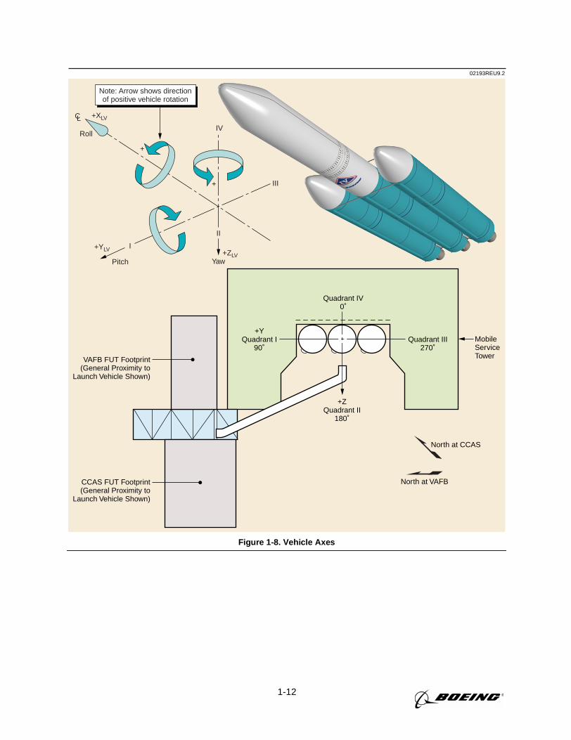
1-12
MobileServiceTower
North at CCAS
North at VAFB
Quadrant IV0˚
Quadrant III270˚
+YQuadrant I
90˚
+ZQuadrant II
180˚
VAFB FUT Footprint(General Proximity to
Launch Vehicle Shown)
CCAS FUT Footprint(General Proximity to
Launch Vehicle Shown)
02193REU9.2
IV
+
+
+ZLV+YLV
III
I
II
YawPitch
Roll
+XLVCL
Note: Arrow shows directionof positive vehicle rotation
Figure 1-8. Vehicle Axes
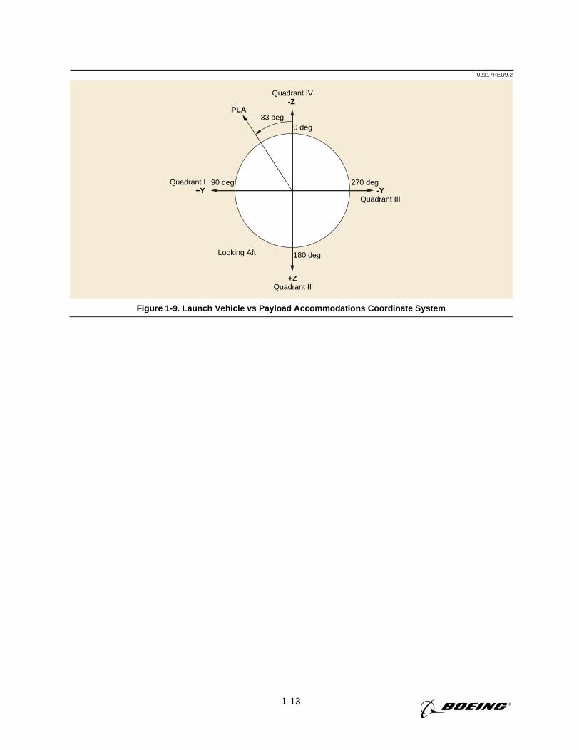
1-13
02117REU9.2
Quadrant IV-Z
+ZQuadrant II
180 deg
270 deg
0 deg33 deg
PLA
90 deg
Looking Aft
Quadrant I +Y -Y
Quadrant III
Figure 1-9. Launch Vehicle vs Payload Accommodations Coordinate System
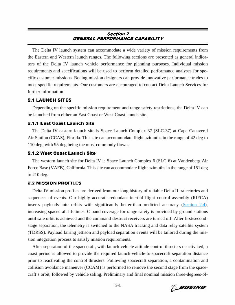
2-1
Section 2
GENERAL PERFORMANCE CAPABILITY
The Delta IV launch system can accommodate a wide variety of mission requirements from
the Eastern and Western launch ranges. The following sections are presented as general indica-
tors of the Delta IV launch vehicle performance for planning purposes. Individual mission
requirements and specifications will be used to perform detailed performance analyses for spe-
cific customer missions. Boeing mission designers can provide innovative performance trades to
meet specific requirements. Our customers are encouraged to contact Delta Launch Services for
further information.
2.1 LAUNCH SITES
Depending on the specific mission requirement and range safety restrictions, the Delta IV can
be launched from either an East Coast or West Coast launch site.
2.1.1 East Coast Launch Site
The Delta IV eastern launch site is Space Launch Complex 37 (SLC-37) at Cape Canaveral
Air Station (CCAS), Florida. This site can accommodate flight azimuths in the range of 42 deg to
110 deg, with 95 deg being the most commonly flown.
2.1.2 West Coast Launch Site
The western launch site for Delta IV is Space Launch Complex 6 (SLC-6) at Vandenberg Air
Force Base (VAFB), California. This site can accommodate flight azimuths in the range of 151 deg
to 210 deg.
2.2 MISSION PROFILES
Delta IV mission profiles are derived from our long history of reliable Delta II trajectories and
sequences of events. Our highly accurate redundant inertial flight control assembly (RIFCA)
inserts payloads into orbits with significantly better-than-predicted accuracy (Section 2.4),
increasing spacecraft lifetimes. C-band coverage for range safety is provided by ground stations
until safe orbit is achieved and the command-destruct receivers are turned off. After first/second-
stage separation, the telemetry is switched to the NASA tracking and data relay satellite system
(TDRSS). Payload fairing jettison and payload separation events will be tailored during the mis-
sion integration process to satisfy mission requirements.
After separation of the spacecraft, with launch vehicle attitude control thrusters deactivated, a
coast period is allowed to provide the required launch-vehicle-to-spacecraft separation distance
prior to reactivating the control thrusters. Following spacecraft separation, a contamination and
collision avoidance maneuver (CCAM) is performed to remove the second stage from the space-
craft’s orbit, followed by vehicle safing. Preliminary and final nominal mission three-degrees-of-
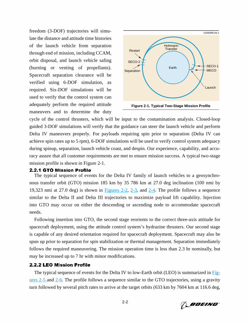
2-2
freedom (3-DOF) trajectories will simu-
late the distance and attitude time histories
of the launch vehicle from separation
through end of mission, including CCAM,
orbit disposal, and launch vehicle safing
(burning or venting of propellants).
Spacecraft separation clearance will be
verified using 6-DOF simulation, as
required. Six-DOF simulations will be
used to verify that the control system can
adequately perform the required attitude
maneuvers and to determine the duty
cycle of the control thrusters, which will be input to the contamination analysis. Closed-loop
guided 3-DOF simulations will verify that the guidance can steer the launch vehicle and perform
Delta IV maneuvers properly. For payloads requiring spin prior to separation (Delta IV can
achieve spin rates up to 5 rpm), 6-DOF simulations will be used to verify control system adequacy
during spinup, separation, launch vehicle coast, and despin. Our experience, capability, and accu-
racy assure that all customer requirements are met to ensure mission success. A typical two-stage
mission profile is shown in Figure 2-1.
2.2.1 GTO Mission ProfileThe typical sequence of events for the Delta IV family of launch vehicles to a geosynchro-
nous transfer orbit (GTO) mission 185 km by 35 786 km at 27.0 deg inclination (100 nmi by
19,323 nmi at 27.0 deg) is shown inFigures 2-2, 2-3, and2-4. The profile follows a sequence
similar to the Delta II and Delta III trajectories to maximize payload lift capability. Injection
into GTO may occur on either the descending or ascending node to accommodate spacecraft
needs.
Following insertion into GTO, the second stage reorients to the correct three-axis attitude for
spacecraft deployment, using the attitude control system’s hydrazine thrusters. Our second stage
is capable of any desired orientation required for spacecraft deployment. Spacecraft may also be
spun up prior to separation for spin stabilization or thermal management. Separation immediately
follows the required maneuvering. The mission operation time is less than 2.3 hr nominally, but
may be increased up to 7 hr with minor modifications.
2.2.2 LEO Mission Profile
The typical sequence of events for the Delta IV to low-Earth orbit (LEO) is summarized inFig-
ures 2-5and2-6. The profile follows a sequence similar to the GTO trajectories, using a gravity
turn followed by several pitch rates to arrive at the target orbits (633 km by 7604 km at 116.6 deg,
02083REU9.2
HohmannTransferRestart
SECO-2SECO-1MECO
Launch
SeparationEarth
Figure 2-1. Typical Two-Stage Mission Profile
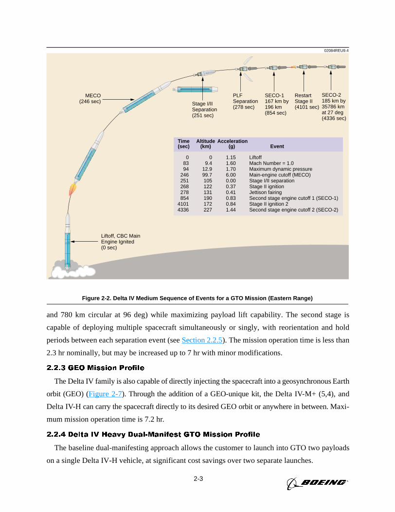
2-3
and 780 km circular at 96 deg) while maximizing payload lift capability. The second stage is
capable of deploying multiple spacecraft simultaneously or singly, with reorientation and hold
periods between each separation event (seeSection 2.2.5). The mission operation time is less than
2.3 hr nominally, but may be increased up to 7 hr with minor modifications.
2.2.3 GEO Mission Profile
The Delta IV family is also capable of directly injecting the spacecraft into a geosynchronous Earth
orbit (GEO) (Figure 2-7). Through the addition of a GEO-unique kit, the Delta IV-M+ (5,4), and
Delta IV-H can carry the spacecraft directly to its desired GEO orbit or anywhere in between. Maxi-
mum mission operation time is 7.2 hr.
2.2.4 Delta IV Heavy Dual-Manifest GTO Mission Profile
The baseline dual-manifesting approach allows the customer to launch into GTO two payloads
on a single Delta IV-H vehicle, at significant cost savings over two separate launches.
02084REU9.4
Liftoff, CBC MainEngine Ignited(0 sec)
MECO(246 sec) Stage I/II
Separation(251 sec)
PLF Separation(278 sec)
SECO-1167 km by196 km (854 sec)
SECO-2185 km by35786 kmat 27 deg (4336 sec)
RestartStage II(4101 sec)
Time Altitude Acceleration(sec) (km) (g) Event
0 0 1.15 Liftoff83 9.4 1.60 Mach Number = 1.094 12.9 1.70 Maximum dynamic pressure
246 99.7 6.00 Main-engine cutoff (MECO)251 105 0.00 Stage I/II separation268 122 0.37 Stage II ignition278 131 0.41 Jettison fairing854 190 0.83 Second stage engine cutoff 1 (SECO-1)
4101 172 0.84 Stage II ignition 24336 227 1.44 Second stage engine cutoff 2 (SECO-2)
Figure 2-2. Delta IV Medium Sequence of Events for a GTO Mission (Eastern Range)
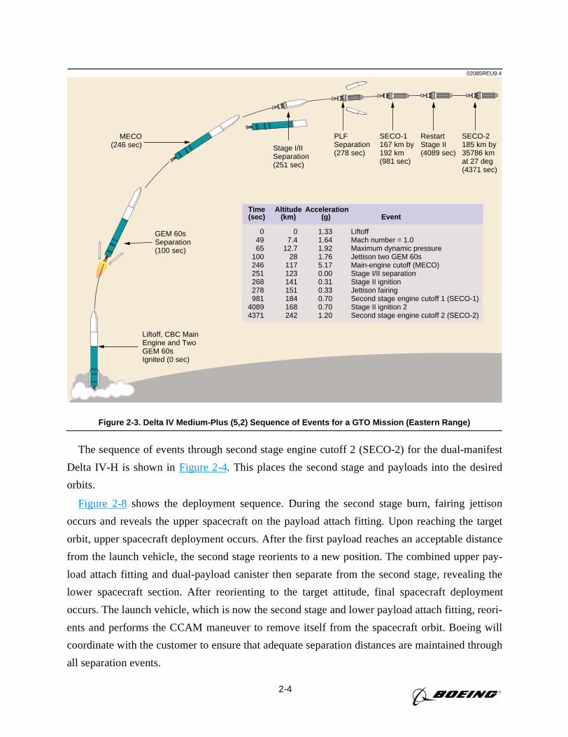
2-4
The sequence of events through second stage engine cutoff 2 (SECO-2) for the dual-manifest
Delta IV-H is shown inFigure 2-4. This places the second stage and payloads into the desired
orbits.
Figure 2-8shows the deployment sequence. During the second stage burn, fairing jettison
occurs and reveals the upper spacecraft on the payload attach fitting. Upon reaching the target
orbit, upper spacecraft deployment occurs. After the first payload reaches an acceptable distance
from the launch vehicle, the second stage reorients to a new position. The combined upper pay-
load attach fitting and dual-payload canister then separate from the second stage, revealing the
lower spacecraft section. After reorienting to the target attitude, final spacecraft deployment
occurs. The launch vehicle, which is now the second stage and lower payload attach fitting, reori-
ents and performs the CCAM maneuver to remove itself from the spacecraft orbit. Boeing will
coordinate with the customer to ensure that adequate separation distances are maintained through
all separation events.
02085REU9.4
Time Altitude Acceleration(sec) (km) (g) Event
0 0 1.33 Liftoff49 7.4 1.64 Mach number = 1.065 12.7 1.92 Maximum dynamic pressure
100 28 1.76 Jettison two GEM 60s246 117 5.17 Main-engine cutoff (MECO)251 123 0.00 Stage I/II separation268 141 0.31 Stage II ignition278 151 0.33 Jettison fairing981 184 0.70 Second stage engine cutoff 1 (SECO-1)
4089 168 0.70 Stage II ignition 24371 242 1.20 Second stage engine cutoff 2 (SECO-2)
Liftoff, CBC MainEngine and TwoGEM 60sIgnited (0 sec)
GEM 60sSeparation(100 sec)
MECO(246 sec) Stage I/II
Separation(251 sec)
PLF Separation(278 sec)
SECO-1167 km by192 km (981 sec)
SECO-2185 km by35786 kmat 27 deg (4371 sec)
RestartStage II(4089 sec)
Figure 2-3. Delta IV Medium-Plus (5,2) Sequence of Events for a GTO Mission (Eastern Range)
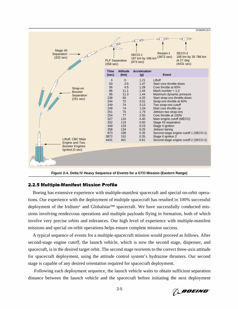
2-5
2.2.5 Multiple-Manifest Mission Profile
Boeing has extensive experience with multiple-manifest spacecraft and special on-orbit opera-
tions. Our experience with the deployment of multiple spacecraft has resulted in 100% successful
deployment of the Iridium® and Globalstar™ spacecraft. We have successfully conducted mis-
sions involving rendezvous operations and multiple payloads flying in formation, both of which
involve very precise orbits and tolerances. Our high level of experience with multiple-manifest
missions and special on-orbit operations helps ensure complete mission success.
A typical sequence of events for a multiple-spacecraft mission would proceed as follows. After
second-stage engine cutoff, the launch vehicle, which is now the second stage, dispenser, and
spacecraft, is in the desired target orbit. The second stage reorients to the correct three-axis attitude
for spacecraft deployment, using the attitude control system’s hydrazine thrusters. Our second
stage is capable of any desired orientation required for spacecraft deployment.
Following each deployment sequence, the launch vehicle waits to obtain sufficient separation
distance between the launch vehicle and the spacecraft before initiating the next deployment
02086REU9.5
Time Altitude Acceleration(sec) (km) (g) Event
0 0 1.21 Liftoff 50 3.5 1.47 Start core throttle-down 56 4.5 1.28 Core throttle at 60% 86 11.1 1.44 Mach number = 1.0 86 11.3 1.44 Maximum dynamic pressure 238 69 4.20 Start strap-ons throttle-down 244 72 3.01 Strap-ons throttle at 60% 249 74 3.13 Two strap-ons cutoff 249 74 1.04 Start core throttle-up 251 75 1.79 Jettison two strap-ons 254 77 2.50 Core throttle at 100% 327 116 4.40 Main-engine cutoff (MECO) 332 119 0.00 Stage I/II separation 349 129 0.23 Stage II ignition 358 134 0.25 Jettison fairing 873 198 0.35 Second-stage engine cutoff 1 (SECO-1) 3872 152 0.35 Stage II ignition 2 4431 401 0.61 Second-stage engine cutoff 2 (SECO-2)Liftoff, CBC Main
Engine and TwoBooster EnginesIgnited (0 sec)
Strap-onBoosterSeparation(251 sec)
Stage I/IISeparation
(332 sec)SECO-1 167 km by 196 km(873 sec)
Restart-1(3872 sec)
SECO-2185 km by 35 786 kmat 27 deg(4431 sec)
PLF Separation(358 sec)
Figure 2-4. Delta IV Heavy Sequence of Events for a GTO Mission (Eastern Range)
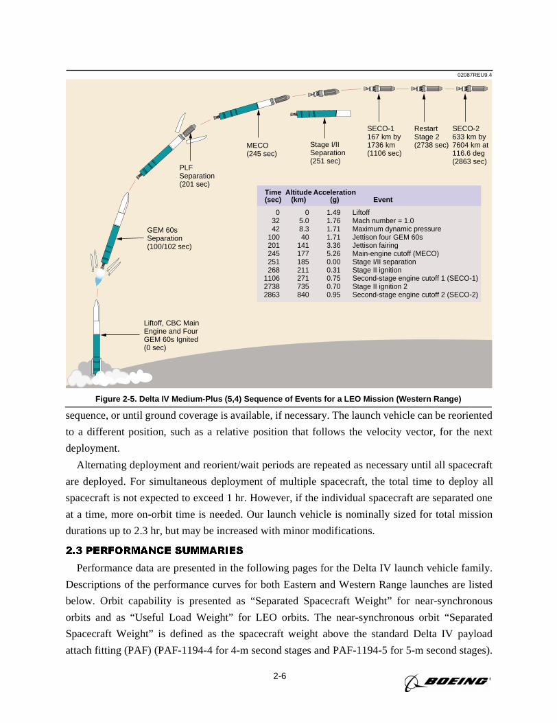
2-6
sequence, or until ground coverage is available, if necessary. The launch vehicle can be reoriented
to a different position, such as a relative position that follows the velocity vector, for the next
deployment.
Alternating deployment and reorient/wait periods are repeated as necessary until all spacecraft
are deployed. For simultaneous deployment of multiple spacecraft, the total time to deploy all
spacecraft is not expected to exceed 1 hr. However, if the individual spacecraft are separated one
at a time, more on-orbit time is needed. Our launch vehicle is nominally sized for total mission
durations up to 2.3 hr, but may be increased with minor modifications.
2.3 PERFORMANCE SUMMARIES
Performance data are presented in the following pages for the Delta IV launch vehicle family.
Descriptions of the performance curves for both Eastern and Western Range launches are listed
below. Orbit capability is presented as “Separated Spacecraft Weight” for near-synchronous
orbits and as “Useful Load Weight” for LEO orbits. The near-synchronous orbit “Separated
Spacecraft Weight” is defined as the spacecraft weight above the standard Delta IV payload
attach fitting (PAF) (PAF-1194-4 for 4-m second stages and PAF-1194-5 for 5-m second stages).
02087REU9.4
Liftoff, CBC MainEngine and FourGEM 60s Ignited(0 sec)
GEM 60sSeparation(100/102 sec)
MECO(245 sec)
Stage I/IISeparation(251 sec)
PLF Separation(201 sec)
SECO-1167 km by1736 km (1106 sec)
SECO-2633 km by7604 km at116.6 deg (2863 sec)
RestartStage 2(2738 sec)
0 0 1.49 Liftoff32 5.0 1.76 Mach number = 1.042 8.3 1.71 Maximum dynamic pressure
100 40 1.71 Jettison four GEM 60s201 141 3.36 Jettison fairing245 177 5.26 Main-engine cutoff (MECO)251 185 0.00 Stage I/II separation268 211 0.31 Stage II ignition
1106 271 0.75 Second-stage engine cutoff 1 (SECO-1)2738 735 0.70 Stage II ignition 22863 840 0.95 Second-stage engine cutoff 2 (SECO-2)
Time(sec)
Altitude(km)
Acceleration(g) Event
Figure 2-5. Delta IV Medium-Plus (5,4) Sequence of Events for a LEO Mission (Western Range)
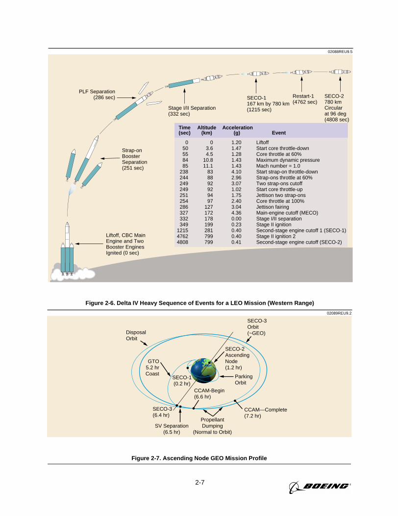
2-7
02088REU9.5
Time Altitude Acceleration(sec) (km) (g) Event
0 0 1.20 Liftoff 50 3.6 1.47 Start core throttle-down 55 4.5 1.28 Core throttle at 60% 84 10.8 1.43 Maximum dynamic pressure 85 11.1 1.43 Mach number = 1.0 238 83 4.10 Start strap-on throttle-down 244 88 2.96 Strap-ons throttle at 60% 249 92 3.07 Two strap-ons cutoff 249 92 1.02 Start core throttle-up 251 94 1.75 Jettison two strap-ons 254 97 2.40 Core throttle at 100% 286 127 3.04 Jettison fairing 327 172 4.36 Main-engine cutoff (MECO) 332 178 0.00 Stage I/II separation 349 199 0.23 Stage II ignition 1215 281 0.40 Second-stage engine cutoff 1 (SECO-1) 4762 799 0.40 Stage II ignition 2 4808 799 0.41 Second-stage engine cutoff (SECO-2)
Liftoff, CBC MainEngine and TwoBooster EnginesIgnited (0 sec)
Strap-onBoosterSeparation(251 sec)
PLF Separation(286 sec) SECO-1
167 km by 780 km(1215 sec)Stage I/II Separation
(332 sec)
Restart-1(4762 sec)
SECO-2780 km Circularat 96 deg(4808 sec)
Figure 2-6. Delta IV Heavy Sequence of Events for a LEO Mission (Western Range)
02089REU9.2
GTO5.2 hrCoast
SECO-1(0.2 hr)
SV Separation(6.5 hr)
PropellantDumping
(Normal to Orbit)
ParkingOrbit
SECO-2AscendingNode(1.2 hr)
SECO-3Orbit(~GEO)
SECO-3(6.4 hr)
CCAM-Begin(6.6 hr)
CCAM—Complete(7.2 hr)
Disposal Orbit
Figure 2-7. Ascending Node GEO Mission Profile
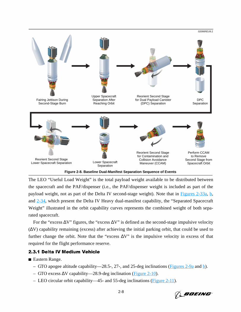
2-8
The LEO “Useful Load Weight” is the total payload weight available to be distributed between
the spacecraft and the PAF/dispenser (i.e., the PAF/dispenser weight is included as part of the
payload weight, not as part of the Delta IV second-stage weight). Note that inFigures 2-33a, b,
and2-34, which present the Delta IV Heavy dual-manifest capability, the “Separated Spacecraft
Weight” illustrated in the orbit capability curves represents the combined weight of both sepa-
rated spacecraft.
For the “excess∆V” figures, the “excess∆V” is defined as the second-stage impulsive velocity
(∆V) capability remaining (excess) after achieving the initial parking orbit, that could be used to
further change the orbit. Note that the “excess∆V” is the impulsive velocity in excess of that
required for the flight performance reserve.
2.3.1 Delta IV Medium Vehicle
Eastern Range.
– GTO apogee altitude capability—28.5-, 27-, and 25-deg inclinations (Figures 2-9aandb).
– GTO excess∆V capability—28.9-deg inclination (Figure 2-10).
– LEO circular orbit capability—45- and 55-deg inclinations (Figure 2-11).
02090REU9.2
Fairing Jettison DuringSecond-Stage Burn
Upper SpacecraftSeparation AfterReaching Orbit
Lower SpacecraftSeparation
Reorient Second Stagefor Dual Payload Canister
(DPC) Separation
Reorient Second StageLower Spacecraft Separation
Reorient Second Stagefor Contamination and
Collision AvoidanceManeuver (CCAM)
Perform CCAMto Remove
Second Stage fromSpacecraft Orbit
DPCSeparation
Figure 2-8. Baseline Dual-Manifest Separation Sequence of Events
2-9
– LEO excess∆V capability—45- and 55-deg inclinations (Figure 2-12).
Western Range.
– LEO circular orbit capability—63.4-deg inclination and sun-synchronous (Figure 2-13).
– LEO excess∆V capability—63.4-deg inclination and sun-synchronous (Figure 2-14).
2.3.2 Delta IV Medium-Plus (4,2) Vehicle
Eastern Range.
– GTO apogee altitude capability—28.5-, 27-, and 25-deg inclinations (Figure 2-15aandb).
– GTO excess∆V capability—28.9-deg inclination (Figure 2-16).
– LEO circular orbit capability—45- and 55-deg inclinations (Figure 2-17).
– LEO excess∆V capability—45- and 55-deg inclinations (Figure 2-18).
Western Range.
– LEO circular orbit capability—63.4-deg inclination and sun-synchronous (Figure 2-19).
– LEO excess∆V capability—63.4-deg inclination and sun-synchronous (Figure 2-20).
2.3.3 Delta IV Medium-Plus (5,2) Vehicle
Eastern Range.
– GTO apogee altitude capability—28.5-, 27-, and 25-deg inclinations (Figures 2-21aandb).
– GTO excess∆V capability—28.9-deg inclination (Figure 2-22).
– LEO circular orbit capability—45- and 55-deg inclinations (Figure 2-23).
– LEO excess∆V capability—45- and 55-deg inclinations (Figure 2-24).
Western Range.
– LEO circular orbit capability—63.4-deg inclination and sun-synchronous (Figure 2-25).
– LEO excess∆V capability—63.4-deg inclination and sun-synchronous (Figure 2-26).
2.3.4 Delta IV Medium-Plus (5,4) Vehicle
Eastern Range.
– GTO apogee altitude capability—28.5-, 27-, and 25-deg inclinations (Figures 2-27aandb).
– GTO excess∆V capability—28.9-deg inclination (Figure 2-28).
– LEO circular orbit capability—45- and 55-deg inclinations (Figure 2-29).
– LEO excess∆V capability—45- and 55-deg inclinations (Figure 2-30).
Western Range.
– LEO circular orbit capability—63.4-deg inclination and sun-synchronous (Figure 2-31).
– LEO excess∆V capability—63.4-deg inclination and sun-synchronous (Figure 2-32).
2.3.5 Delta IV Heavy Vehicle
Eastern Range.
– GTO apogee altitude dual manifest—28.5-, 27-, and 25-deg inclinations (Figures 2-33aandb).
– GTO excess∆V capability dual manifest—28.9-deg inclination (Figure 2-34).
2-10
– LEO circular orbit capability—45- and 55-deg inclinations (Figure 2-35).
– LEO excess∆V capability—45- and 55-deg inclinations (Figure 2-36).
Western Range.
– LEO circular orbit capability—63.4-deg inclination and sun-synchronous (Figure 2-37).
– LEO excess∆V capability—63.4-deg inclination and sun-synchronous (Figure 2-38).
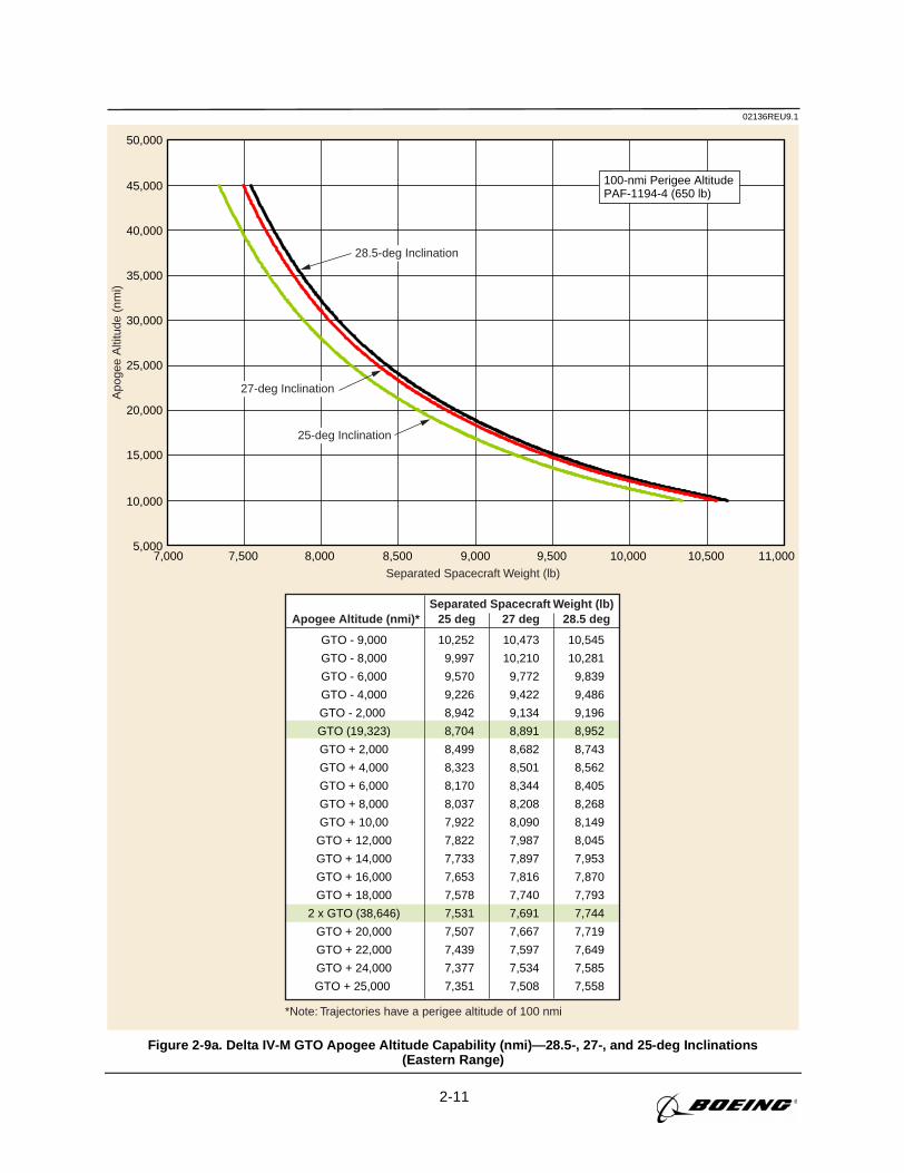
2-11
02136REU9.1A
poge
e A
ltitu
de (
nmi)
Separated Spacecraft Weight (lb)
*Note: Trajectories have a perigee altitude of 100 nmi
Separated Spacecraft Weight (lb)
7,000 7,500 8,000 8,500 9,000 9,500 10,000 10,500 11,000
100-nmi Perigee AltitudePAF-1194-4 (650 lb)
Apogee Altitude (nmi)* 25 deg 27 deg 28.5 deg
GTO - 9,000
GTO - 8,000
GTO - 6,000
GTO - 4,000
GTO - 2,000
GTO (19,323)
GTO + 2,000
GTO + 4,000
GTO + 6,000
GTO + 8,000
GTO + 10,00
GTO + 12,000
GTO + 14,000
GTO + 16,000
GTO + 18,000
2 x GTO (38,646)
GTO + 20,000
GTO + 22,000
GTO + 24,000
GTO + 25,000
10,252
9,997
9,570
9,226
8,942
8,704
8,499
8,323
8,170
8,037
7,922
7,822
7,733
7,653
7,578
7,531
7,507
7,439
7,377
7,351
10,473
10,210
9,772
9,422
9,134
8,891
8,682
8,501
8,344
8,208
8,090
7,987
7,897
7,816
7,740
7,691
7,667
7,597
7,534
7,508
10,545
10,281
9,839
9,486
9,196
8,952
8,743
8,562
8,405
8,268
8,149
8,045
7,953
7,870
7,793
7,744
7,719
7,649
7,585
7,558
5,000
10,000
15,000
20,000
25,000
30,000
35,000
40,000
45,000
50,000
28.5-deg Inclination
27-deg Inclination
25-deg Inclination
Figure 2-9a. Delta IV-M GTO Apogee Altitude Capability (nmi)—28.5-, 27-, and 25-deg Inclinations(Eastern Range)
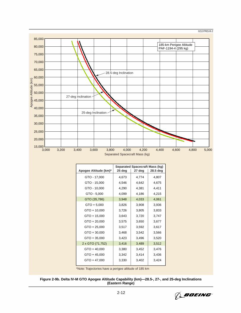
2-12
02137REU9.2A
poge
e A
ltitu
de (
km)
Separated Spacecraft Mass (kg)
*Note: Trajectories have a perigee altitude of 185 km
Separated Spacecraft Mass (kg)
185-km Perigee AltitudePAF-1194-4 (295 kg)
Apogee Altitude (km)* 25 deg 27 deg 28.5 deg
GTO - 17,000
GTO - 15,000
GTO - 10,000
GTO - 5,000
GTO (35,786)
GTO + 5,000
GTO + 10,000
GTO + 15,000
GTO + 20,000
GTO + 25,000
GTO + 30,000
GTO + 35,000
2 x GTO (71,752)
GTO + 40,000
GTO + 45,000
GTO + 47,000
4,673
4,546
4,290
4,099
3,948
3,826
3,726
3,643
3,575
3,517
3,468
3,423
3,416
3,380
3,342
3,330
4,774
4,642
4,381
4,186
4,033
3,908
3,805
3,720
3,650
3,592
3,542
3,496
3,489
3,452
3,414
3,402
4,807
4,675
4,411
4,215
4,061
3,936
3,833
3,747
3,677
3,617
3,566
3,520
3,512
3,476
3,436
3,424
28.5-deg Inclination
27-deg Inclination
25-deg Inclination
15,000
20,000
25,000
30,000
35,000
40,000
45,000
50,000
55,000
60,000
65,000
70,000
75,000
80,000
85,000
3,000 3,200 3,400 3,600 3,800 4,000 4,200 4,400 4,600 4,800 5,000
Figure 2-9b. Delta IV-M GTO Apogee Altitude Capability (km)—28.5-, 27-, and 25-deg Inclinations(Eastern Range)
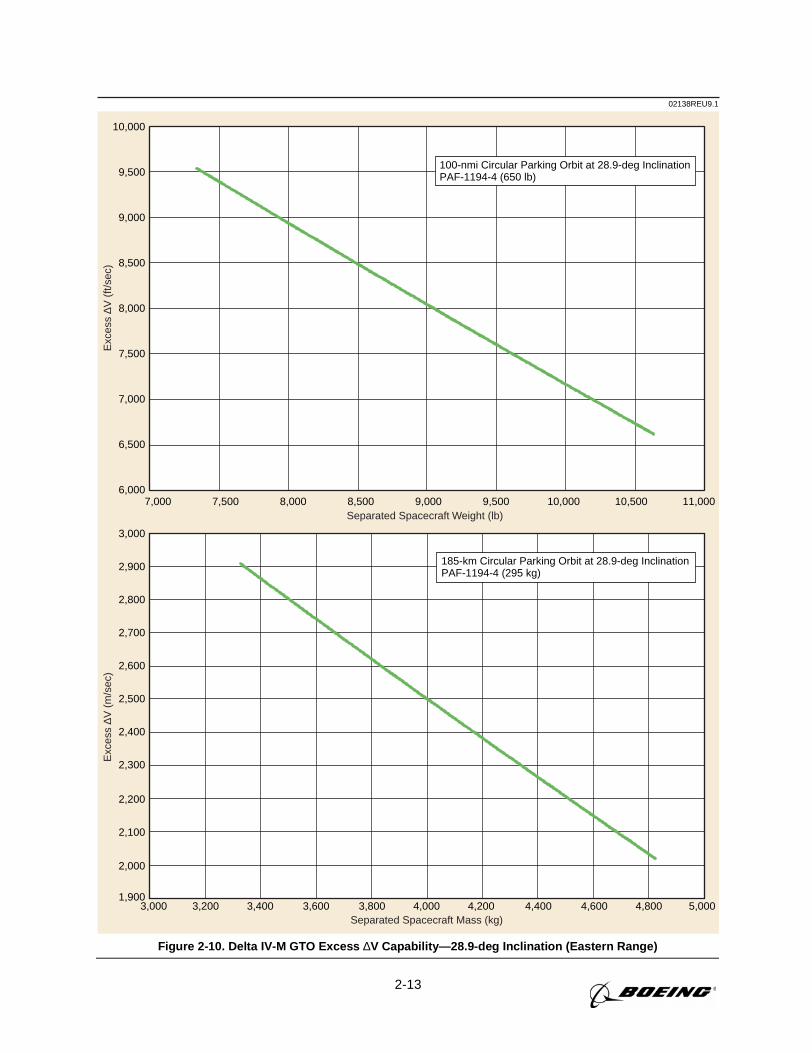
2-13
02138REU9.1E
xces
s ∆V
(ft/
sec)
Exc
ess
∆V (
m/s
ec)
Separated Spacecraft Weight (lb)
Separated Spacecraft Mass (kg)
7,000 7,500 8,000 8,500 9,000 9,500 10,000 10,500 11,0006,000
6,500
7,000
7,500
8,000
8,500
9,000
9,500
10,000
100-nmi Circular Parking Orbit at 28.9-deg InclinationPAF-1194-4 (650 lb)
1,900
2,000
2,100
2,200
2,300
2,400
2,500
2,600
2,700
2,800
2,900
3,000
3,000 3,200 3,400 3,600 3,800 4,000 4,200 4,400 4,600 4,800 5,000
185-km Circular Parking Orbit at 28.9-deg InclinationPAF-1194-4 (295 kg)
Figure 2-10. Delta IV-M GTO Excess ∆V Capability—28.9-deg Inclination (Eastern Range)
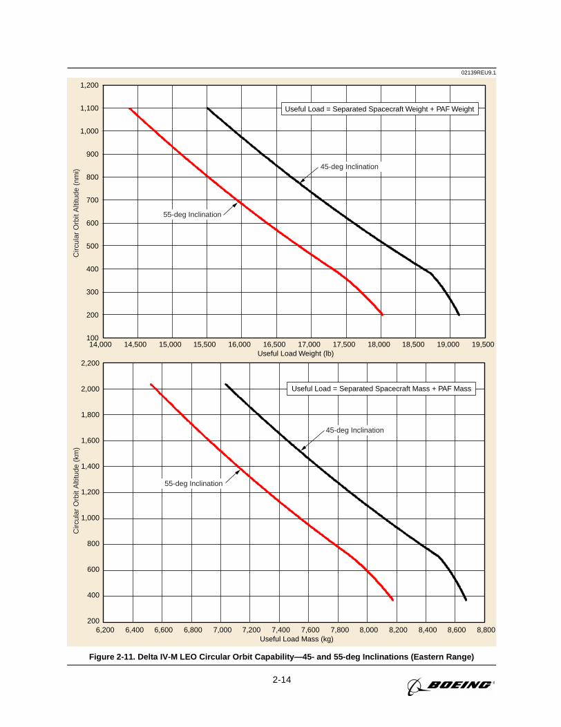
2-14
02139REU9.1C
ircul
ar O
rbit
Alti
tude
(km
)
200
400
600
800
1,000
1,200
1,400
1,600
1,800
2,000
2,200
6,200 6,400 6,600 6,800 7,000 7,200 7,400 7,600 7,800 8,000 8,200 8,400 8,600 8,800Useful Load Mass (kg)
Useful Load = Separated Spacecraft Mass + PAF Mass
Circ
ular
Orb
it A
ltitu
de (
nmi)
100
200
300
400
500
600
700
800
900
1,000
1,100
1,200
14,000 14,500 15,000 15,500 16,000 16,500 17,000 17,500 18,000 18,500 19,000 19,500Useful Load Weight (lb)
45-deg Inclination
55-deg Inclination
Useful Load = Separated Spacecraft Weight + PAF Weight
45-deg Inclination
55-deg Inclination
Figure 2-11. Delta IV-M LEO Circular Orbit Capability—45- and 55-deg Inclinations (Eastern Range)
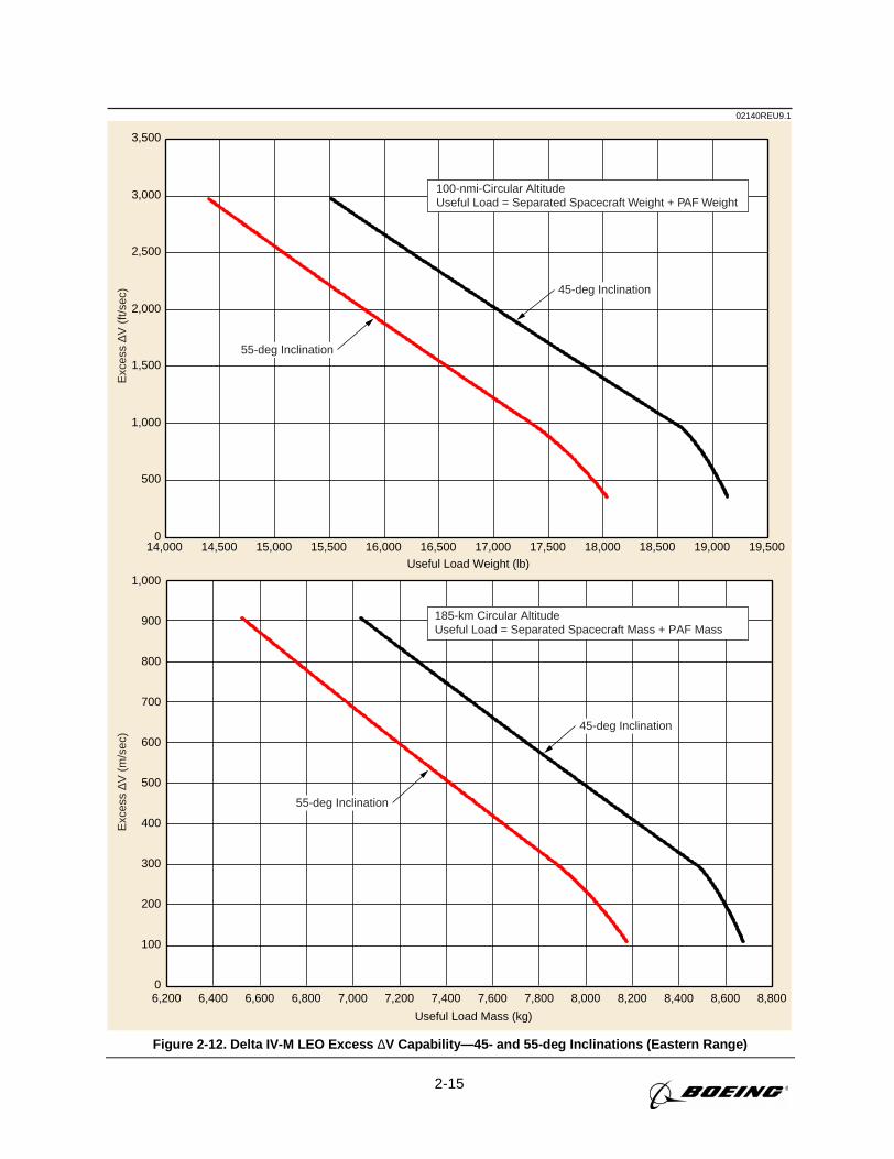
2-15
02140REU9.1E
xces
s ∆V
(m
/sec
)
0
100
200
300
400
500
600
700
800
900
1,000
6,200 6,400 6,600 6,800 7,000 7,200 7,400 7,600 7,800 8,000 8,200 8,400 8,600 8,800
Useful Load Mass (kg)
185-km Circular AltitudeUseful Load = Separated Spacecraft Mass + PAF Mass
Useful Load Weight (lb)
Exc
ess
∆V (
ft/se
c)
0
500
1,000
1,500
2,000
2,500
3,000
3,500
14,000 14,500 15,000 15,500 16,000 16,500 17,000 17,500 18,000 18,500 19,000 19,500
100-nmi-Circular AltitudeUseful Load = Separated Spacecraft Weight + PAF Weight
55-deg Inclination
45-deg Inclination
55-deg Inclination
45-deg Inclination
Figure 2-12. Delta IV-M LEO Excess ∆V Capability—45- and 55-deg Inclinations (Eastern Range)
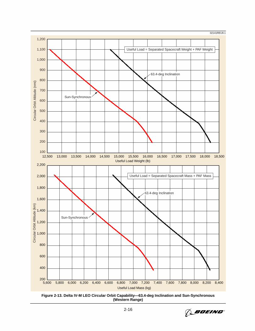
2-16
02141REU9.1C
ircul
ar O
rbit
Alti
tude
(km
)C
ircul
ar O
rbit
Alti
tude
(nm
i)
200
400
600
800
1,000
1,200
1,400
1,600
1,800
2,000
2,200
5,8005,600 6,000 6,200 6,400 6,600 6,800 7,000 7,200 7,400 7,600 7,800 8,000 8,200 8,400
Useful Load Mass (kg)
Useful Load Weight (lb)
Useful Load = Separated Spacecraft Mass + PAF Mass
12,500 13,000 13,500 14,000 14,500 15,000 15,500 16,000 16,500 17,000 17,500 18,000 18,500
1,200
1,100
1,000
900
800
700
600
500
400
300
200
100
Useful Load = Separated Spacecraft Weight + PAF Weight
63.4-deg Inclination
Sun-Synchronous
63.4-deg Inclination
Sun-Synchronous
Figure 2-13. Delta IV-M LEO Circular Orbit Capability—63.4-deg Inclination and Sun-Synchronous(Western Range)
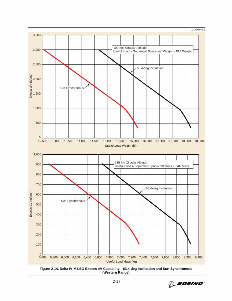
2-17
02142REU9.1E
xces
s ∆V
(m
/sec
)E
xces
s ∆V
(ft/
sec)
5,600 5,800 6,000 6,200 6,400 6,600 6,800 7,000 7,200 7,400 7,600 7,800 8,000 8,200 8,400Useful Load Mass (kg)
1,000
900
800
700
600
500
400
300
200
100
0
185-km Circular AltitudeUseful Load = Separated Spacecraft Mass + PAF Mass
12,500 13,000 13,500 14,000 14,500 15,000 15,500 16,000 16,500 17,000 17,500 18,000 18,500
Useful Load Weight (lb)
3,500
3,000
2,500
2,000
1,500
1,000
500
0
100-nmi Circular AltitudeUseful Load = Separated Spacecraft Weight + PAF Weight
63.4-deg Inclination
Sun-Synchronous
63.4-deg Inclination
Sun-Synchronous
Figure 2-14. Delta IV-M LEO Excess ∆V Capability—63.4-deg Inclination and Sun-Synchronous(Western Range)
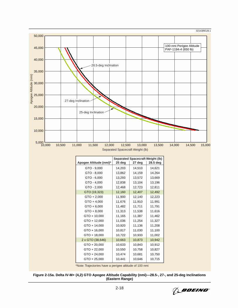
2-18
10,000 10,500 11,000 11,500 12,000 12,500 13,000 13,500 14,000 14,500 15,000
02143REU9.1A
poge
e A
ltitu
de (
nmi)
Separated Spacecraft Weight (lb)
*Note: Trajectories have a perigee altitude of 100 nmi
Separated Spacecraft Weight (lb)
100-nmi Perigee AltitudePAF-1194-4 (650 lb)
Apogee Altitude (nmi)* 25 deg 27 deg 28.5 deg
GTO - 9,000
GTO - 8,000
GTO - 6,000
GTO - 4,000
GTO - 2,000
GTO (19,323)
GTO + 2,000
GTO + 4,000
GTO + 6,000
GTO + 8,000
GTO + 10,000
GTO + 12,000
GTO + 14,000
GTO + 16,000
GTO + 18,000
2 x GTO (38,646)
GTO + 20,000
GTO + 22,000
GTO + 24,000
GTO + 25,000
14,203
13,862
13,293
12,838
12,468
12,160
11,900
11,676
11,482
11,313
11,165
11,036
10,920
10,817
10,722
10,663
10,633
10,550
10,474
10,441
14,510
14,159
13,572
13,104
12,723
12,407
12,140
11,910
11,711
11,538
11,387
11,254
11,136
11,030
10,933
10,873
10,843
10,758
10,681
10,646
14,621
14,264
13,669
13,196
12,811
12,492
12,223
11,991
11,791
11,616
11,462
11,327
11,208
11,100
11,002
10,942
10,912
10,827
10,750
10,715
5,000
10,000
15,000
20,000
25,000
30,000
35,000
40,000
45,000
50,000
28.5-deg Inclination
27-deg Inclination
25-deg Inclination
Figure 2-15a. Delta IV-M+ (4,2) GTO Apogee Altitude Capability (nmi)—28.5-, 27-, and 25-deg Inclinations(Eastern Range)
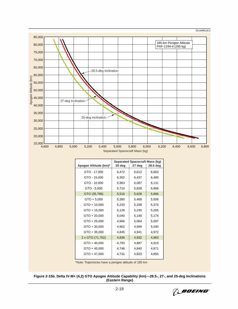
2-19
02144REU9.2A
poge
e A
ltitu
de (
km)
Separated Spacecraft Mass (kg)
*Note: Trajectories have a perigee altitude of 185 km
Separated Spacecraft Mass (kg)
185-km Perigee AltitudePAF-1194-4 (295 kg)
Apogee Altitude (km)* 25 deg 27 deg 28.5 deg
GTO - 17,000
GTO - 15,000
GTO - 10,000
GTO - 5,000
GTO (35,786)
GTO + 5,000
GTO + 10,000
GTO + 15,000
GTO + 20,000
GTO + 25,000
GTO + 30,000
GTO + 35,000
2 x GTO (71,752)
GTO + 40,000
GTO + 45,000
GTO + 47,000
6,472
6,302
5,963
5,710
5,516
5,360
5,233
5,128
5,040
4,966
4,902
4,845
4,836
4,793
4,746
4,731
6,612
6,437
6,087
5,828
5,628
5,468
5,338
5,230
5,140
5,064
4,999
4,941
4,932
4,887
4,840
4,823
6,663
6,485
6,131
5,868
5,666
5,506
5,374
5,265
5,174
5,097
5,030
4,972
4,963
4,919
4,871
4,855
28.5-deg Inclination
27-deg Inclination
25-deg Inclination
15,000
20,000
25,000
30,000
35,000
40,000
45,000
50,000
55,000
60,000
65,000
70,000
75,000
80,000
85,000
4,8004,600 5,000 5,200 5,400 5,600 5,800 6,000 6,200 6,400 6,600 6,800
Figure 2-15b. Delta IV-M+ (4,2) GTO Apogee Altitude Capability (km)—28.5-, 27-, and 25-deg Inclinations(Eastern Range)
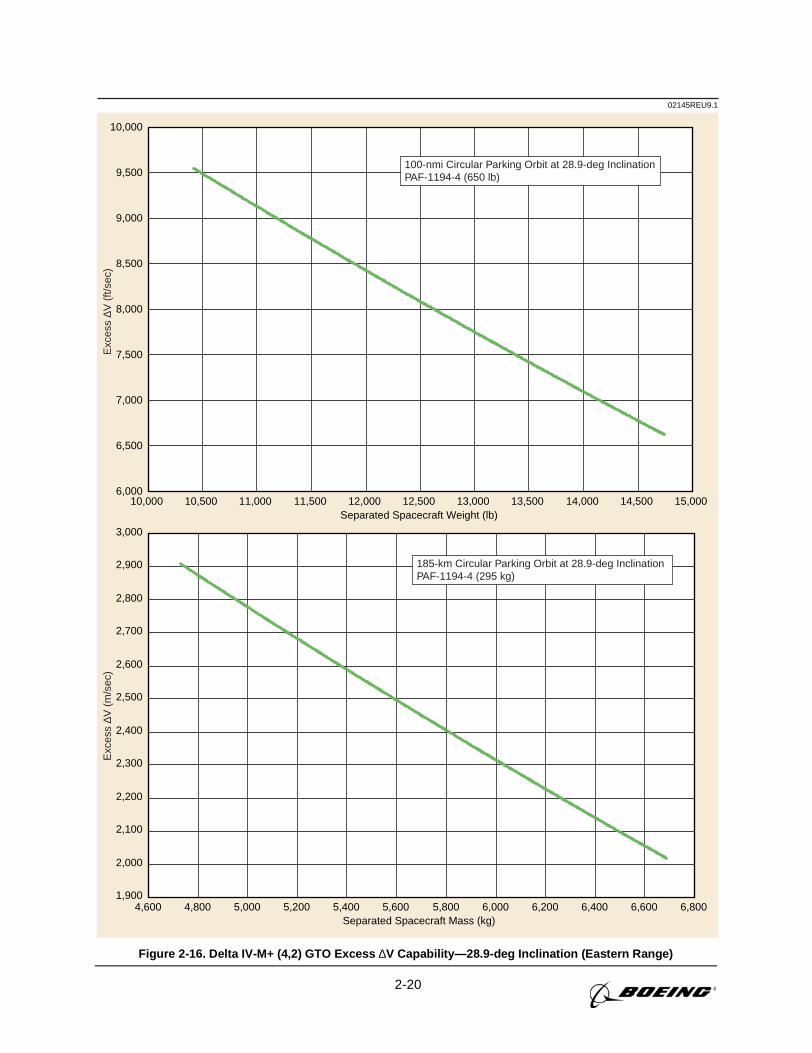
2-20
02145REU9.1
10,000 10,500 11,000 11,500 12,000 12,500Separated Spacecraft Weight (lb)
Separated Spacecraft Mass (kg)
13,000 13,500 14,000 14,500 15,0006,000
6,500
7,000
7,500
8,000
8,500
9,000
9,500
10,000
100-nmi Circular Parking Orbit at 28.9-deg InclinationPAF-1194-4 (650 lb)
Exc
ess
∆V (
ft/se
c)E
xces
s ∆V
(m
/sec
)
4,600 4,800 5,000 5,200 5,400 5,600 5,800 6,000 6,200 6,400 6,600 6,8001,900
2,000
2,100
2,200
2,300
2,400
2,500
2,600
2,700
2,800
2,900
3,000
185-km Circular Parking Orbit at 28.9-deg InclinationPAF-1194-4 (295 kg)
Figure 2-16. Delta IV-M+ (4,2) GTO Excess ∆V Capability—28.9-deg Inclination (Eastern Range)
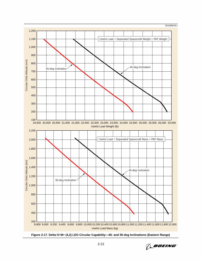
2-21
02146REU9.1C
ircul
ar O
rbit
Alti
tude
(km
)C
ircul
ar O
rbit
Alti
tude
(nm
i)
Useful Load Mass (kg)
Useful Load Weight (lb)
200
400
600
800
1,000
1,200
1,400
1,600
1,800
2,000
2,200
8,800 9,000 9,200 9,400 9,600 9,800 10,000 10,200 10,400 10,600 10,800 11,000 11,200 11,400 11,600 11,800 12,000
Useful Load = Separated Spacecraft Mass + PAF Mass
100
200
300
400
500
600
700
800
900
1,000
1,100
1,200
19,500 20,000 20,500 21,000 21,500 22,000 22,500 23,000 23,500 24,000 24,500 25,000 25,500 26,000 26,500
Useful Load = Separated Spacecraft Weight + PAF Weight
45-deg Inclination55-deg Inclination
45-deg Inclination
55-deg Inclination
Figure 2-17. Delta IV-M+ (4,2) LEO Circular Capability—45- and 55-deg Inclinations (Eastern Range)
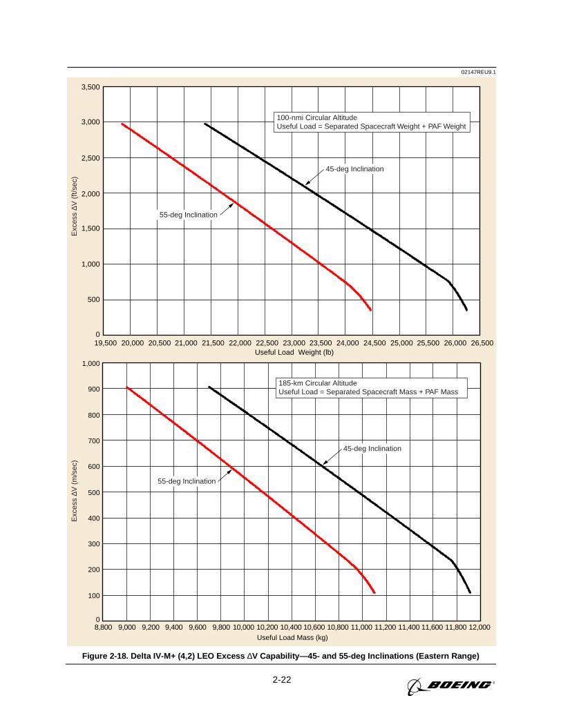
2-22
02147REU9.1E
xces
s ∆V
(m
/sec
)E
xces
s ∆V
(ft/
sec)
Useful Load Mass (kg)
0
100
200
300
400
500
600
700
800
900
1,000
8,800 9,000 9,200 9,400 9,600 9,800 10,000 10,200 10,400 10,600 10,800 11,000 11,200 11,400 11,600 11,800 12,000
185-km Circular AltitudeUseful Load = Separated Spacecraft Mass + PAF Mass
19,500 20,000 20,500 21,000 21,500 22,000 22,500 23,000 23,500 24,000 24,500 25,000 25,500 26,000 26,500Useful Load Weight (lb)
0
500
1,000
1,500
2,000
2,500
3,000
3,500
100-nmi Circular AltitudeUseful Load = Separated Spacecraft Weight + PAF Weight
45-deg Inclination
55-deg Inclination
45-deg Inclination
55-deg Inclination
Figure 2-18. Delta IV-M+ (4,2) LEO Excess ∆V Capability—45- and 55-deg Inclinations (Eastern Range)

2-23
02148REU9.1C
ircul
ar O
rbit
Alti
tude
(km
)
7,600 7,800 8,000 8,200 8,400 8,600 8,800 9,000 9,200 9,400 9,600 9,800 10,000 10,200 10,400 10,600 10,800Useful Load Mass (kg)
200
400
600
800
1,000
1,200
1,400
1,600
1,800
2,000
2,200
Useful Load = Separated Spacecraft Mass + PAF Mass
Circ
ular
Orb
it A
ltitu
de (
nmi)
17,000 17,500 18,000 18,500 19,000 19,500 20,000 20,500 21,000 21,500 22,000 22,500 23,000 23,500 24,000Useful Load Weight (lb)
100
200
300
400
500
600
700
800
900
1,000
1,100
1,200
Useful Load = Separated Spacecraft Weight+ PAF Weight
63.4-deg Inclination
Sun-Synchronous
63.4-deg Inclination
Sun-Synchronous
Figure 2-19. Delta IV-M+ (4,2) LEO Circular Orbit Capability—63.4-deg Inclination and Sun-Synchronous(Western Range)
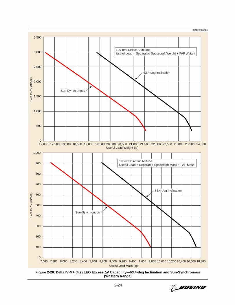
2-24
02149REU9.1E
xces
s ∆V
(m
/sec
)E
xces
s ∆V
(ft/
sec)
7,600 7,800 8,000 8,200 8,400 8,600 8,800 9,000 9,200 9,400 9,600 9,800 10,000 10,200 10,400 10,600 10,800
Useful Load Mass (kg)
0
100
200
300
400
500
600
700
800
900
1,000
185-km Circular AltitudeUseful Load = Separated Spacecraft Mass + PAF Mass
17,000 17,500 18,000 18,500 19,000 19,500 20,000 20,500 21,000 21,500 22,000 22,500 23,000 23,500 24,000Useful Load Weight (lb)
0
500
1,000
1,500
2,000
2,500
3,000
3,500
100-nmi Circular AltitudeUseful Load = Separated Spacecraft Weight + PAF Weight
63.4-deg Inclination
Sun-Synchronous
63.4-deg Inclination
Sun-Synchronous
Figure 2-20. Delta IV-M+ (4,2) LEO Excess ∆V Capability—63.4-deg Inclination and Sun-Synchronous(Western Range)
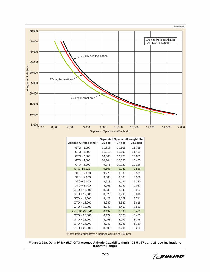
2-25
02150REU9.1A
poge
e A
ltitu
de (
nmi)
Separated Spacecraft Weight (lb)
*Note: Trajectories have a perigee altitude of 100 nmi
Separated Spacecraft Weight (lb)
100-nmi Perigee AltitudePAF-1194-5 (920 lb)
Apogee Altitude (nmi)* 25 deg 27 deg 28.5 deg
GTO - 9,000
GTO - 8,000
GTO - 6,000
GTO - 4,000
GTO - 2,000
GTO (19,323)
GTO + 2,000
GTO + 4,000
GTO + 6,000
GTO + 8,000
GTO + 10,000
GTO + 12,000
GTO + 14,000
GTO + 16,000
GTO + 18,000
2 x GTO (38,646)
GTO + 20,000
GTO + 22,000
GTO + 24,000
GTO + 25,000
11,315
11,012
10,506
10,104
9,778
9,508
9,279
9,083
8,913
8,766
8,636
8,523
8,423
8,332
8,249
8,197
8,172
8,098
8,032
8,002
11,606
11,292
10,770
10,355
10,020
9,743
9,508
9,308
9,134
8,982
8,849
8,733
8,629
8,537
8,452
8,399
8,373
8,299
8,231
8,201
11,719
11,401
10,873
10,455
10,116
9,836
9,599
9,396
9,220
9,067
8,933
8,816
8,711
8,618
8,532
8,479
8,453
8,378
8,310
8,280
5,000
10,000
15,000
20,000
25,000
30,000
35,000
40,000
45,000
50,000
28.5-deg Inclination
27-deg Inclination
25-deg Inclination
7,500 8,000 8,500 9,000 9,500 10,000 10,500 11,000 11,500 12,000
Figure 2-21a. Delta IV-M+ (5,2) GTO Apogee Altitude Capability (nmi)—28.5-, 27-, and 25-deg Inclinations(Eastern Range)
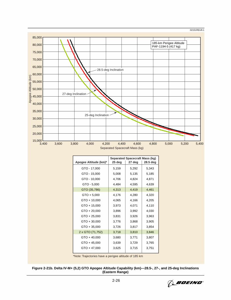
2-26
02151REU9.1A
poge
e A
ltitu
de (
km)
Separated Spacecraft Mass (kg)
*Note: Trajectories have a perigee altitude of 185 km
Separated Spacecraft Mass (kg)
185-km Perigee AltitudePAF-1194-5 (417 kg)
Apogee Altitude (km)* 25 deg 27 deg 28.5 deg
GTO - 17,000
GTO - 15,000
GTO - 10,000
GTO - 5,000
GTO (35,786)
GTO + 5,000
GTO + 10,000
GTO + 15,000
GTO + 20,000
GTO + 25,000
GTO + 30,000
GTO + 35,000
2 x GTO (71,752)
GTO + 40,000
GTO + 45,000
GTO + 47,000
5,159
5,008
4,706
4,484
4,313
4,176
4,065
3,973
3,896
3,831
3,776
3,726
3,718
3,680
3,639
3,625
5,292
5,135
4,824
4,595
4,419
4,280
4,166
4,071
3,992
3,926
3,868
3,817
3,810
3,771
3,729
3,715
5,343
5,185
4,871
4,639
4,461
4,320
4,205
4,110
4,030
3,963
3,905
3,854
3,846
3,807
3,765
3,751
28.5-deg Inclination
27-deg Inclination
25-deg Inclination
15,000
20,000
25,000
30,000
35,000
40,000
45,000
50,000
55,000
60,000
65,000
70,000
75,000
80,000
85,000
3,400 3,600 3,800 4,000 4,200 4,400 4,600 4,800 5,000 5,200 5,400
Figure 2-21b. Delta IV-M+ (5,2) GTO Apogee Altitude Capability (km)—28.5-, 27-, and 25-deg Inclinations(Eastern Range)
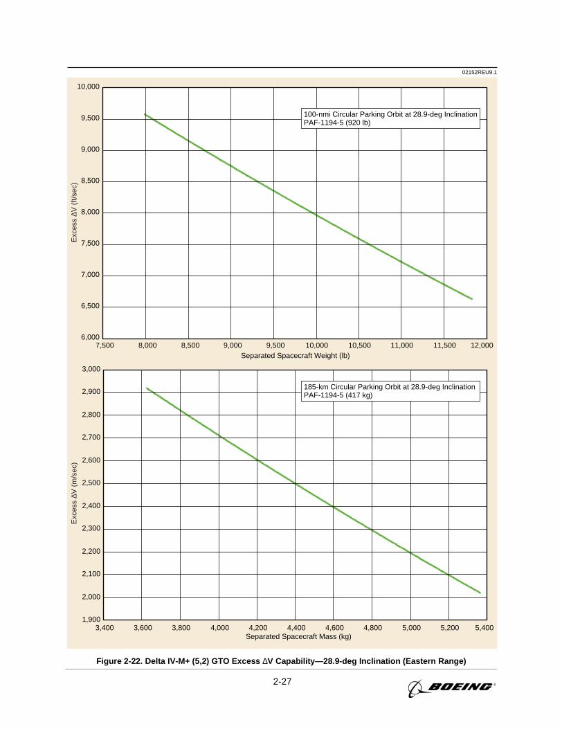
2-27
02152REU9.1E
xces
s ∆V
(m
/sec
)E
xces
s ∆V
(ft/
sec)
3,400 3,600 3,800 4,000 4,200 4,400 4,600 4,800 5,000 5,200 5,400Separated Spacecraft Mass (kg)
1,900
2,000
2,100
2,200
2,300
2,400
2,500
2,600
2,700
2,800
2,900
3,000
185-km Circular Parking Orbit at 28.9-deg InclinationPAF-1194-5 (417 kg)
7,500 8,000 8,500 9,000 9,500 10,000 10,500 11,000 11,500 12,000Separated Spacecraft Weight (lb)
6,000
6,500
7,000
7,500
8,000
8,500
9,000
9,500
10,000
100-nmi Circular Parking Orbit at 28.9-deg InclinationPAF-1194-5 (920 lb)
Figure 2-22. Delta IV-M+ (5,2) GTO Excess ∆V Capability—28.9-deg Inclination (Eastern Range)
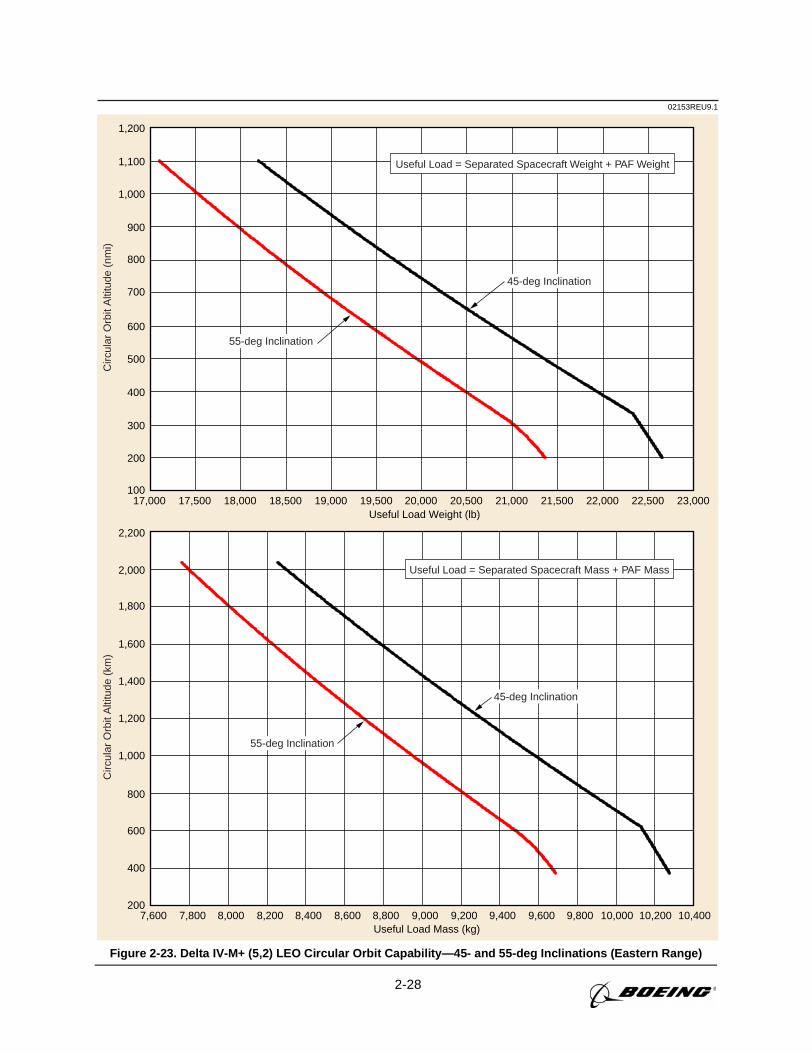
2-28
02153REU9.1C
ircul
ar O
rbit
Alti
tude
(km
)C
ircul
ar O
rbit
Alti
tude
(nm
i)
7,600 7,800 8,000 8,200 8,400 8,600 8,800 9,000 9,200 9,400 9,600 9,800 10,000 10,200 10,400Useful Load Mass (kg)
200
400
600
800
1,000
1,200
1,400
1,600
1,800
2,000
2,200
Useful Load = Separated Spacecraft Mass + PAF Mass
17,000 17,500 18,000 18,500 19,000 19,500 20,000 20,500 21,000 21,500 22,000 22,500 23,000Useful Load Weight (lb)
100
200
300
400
500
600
700
800
900
1,000
1,100
1,200
Useful Load = Separated Spacecraft Weight + PAF Weight
45-deg Inclination
55-deg Inclination
45-deg Inclination
55-deg Inclination
Figure 2-23. Delta IV-M+ (5,2) LEO Circular Orbit Capability—45- and 55-deg Inclinations (Eastern Range)
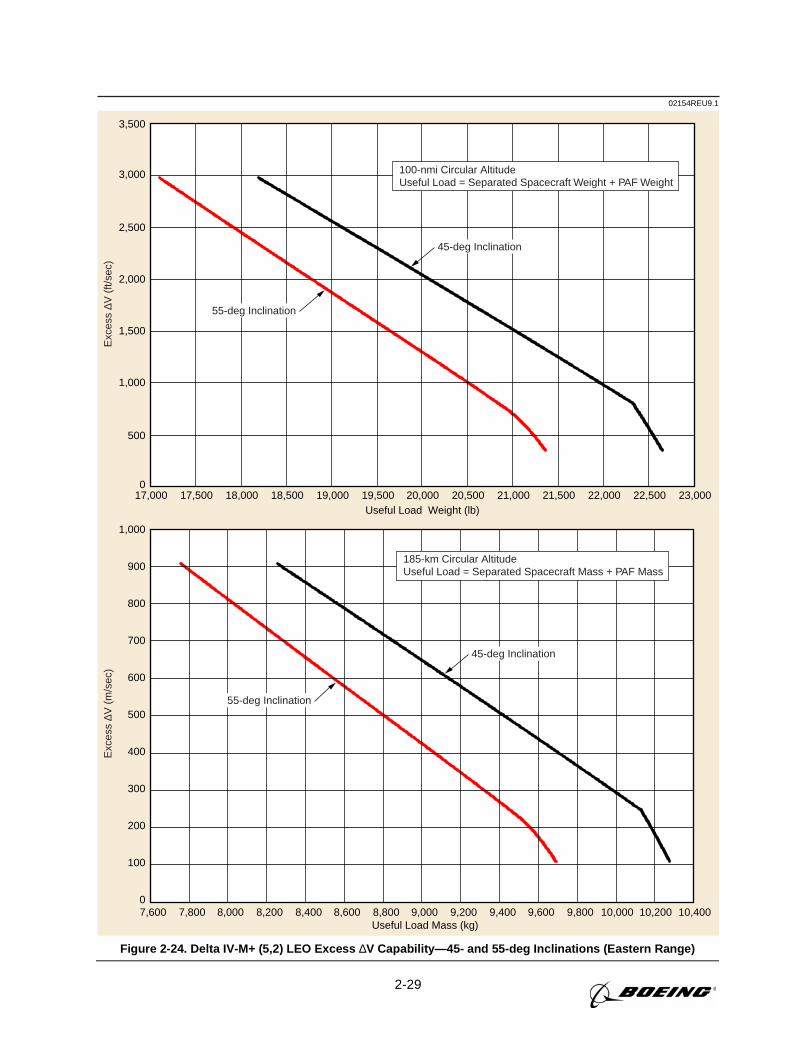
2-29
02154REU9.1E
xces
s ∆V
(m
/sec
)E
xces
s ∆V
(ft/
sec)
7,600 7,800 8,000 8,200 8,400 8,600 8,800 9,000 9,200 9,400 9,600 9,800 10,000 10,200 10,400Useful Load Mass (kg)
0
100
200
300
400
500
600
700
800
900
1,000
185-km Circular AltitudeUseful Load = Separated Spacecraft Mass + PAF Mass
17,000 17,500 18,000 18,500 19,000 19,500 20,000 20,500 21,000 21,500 22,000 22,500 23,000Useful Load Weight (lb)
0
500
1,000
1,500
2,000
2,500
3,000
3,500
100-nmi Circular AltitudeUseful Load = Separated Spacecraft Weight + PAF Weight
45-deg Inclination
55-deg Inclination
45-deg Inclination
55-deg Inclination
Figure 2-24. Delta IV-M+ (5,2) LEO Excess ∆V Capability—45- and 55-deg Inclinations (Eastern Range)
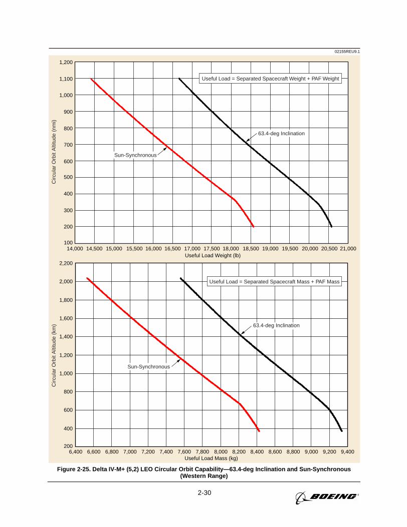
2-30
02155REU9.1C
ircul
ar O
rbit
Alti
tude
(nm
i)C
ircul
ar O
rbit
Alti
tude
(km
)
14,000 14,500 15,000 15,500 16,000 16,500 17,000 17,500 18,000 18,500 19,000 19,500 20,000 20,500 21,000Useful Load Weight (lb)
100
200
300
400
500
600
700
800
900
1,000
1,100
1,200
Useful Load = Separated Spacecraft Weight + PAF Weight
63.4-deg Inclination
Sun-Synchronous
6,400 6,600 6,800 7,000 7,200 7,400 7,600 7,800 8,000 8,200 8,400 8,600 8,800 9,000 9,200 9,400Useful Load Mass (kg)
200
400
600
800
1,000
1,200
1,400
1,600
1,800
2,000
2,200
Useful Load = Separated Spacecraft Mass + PAF Mass
63.4-deg Inclination
Sun-Synchronous
Figure 2-25. Delta IV-M+ (5,2) LEO Circular Orbit Capability—63.4-deg Inclination and Sun-Synchronous(Western Range)
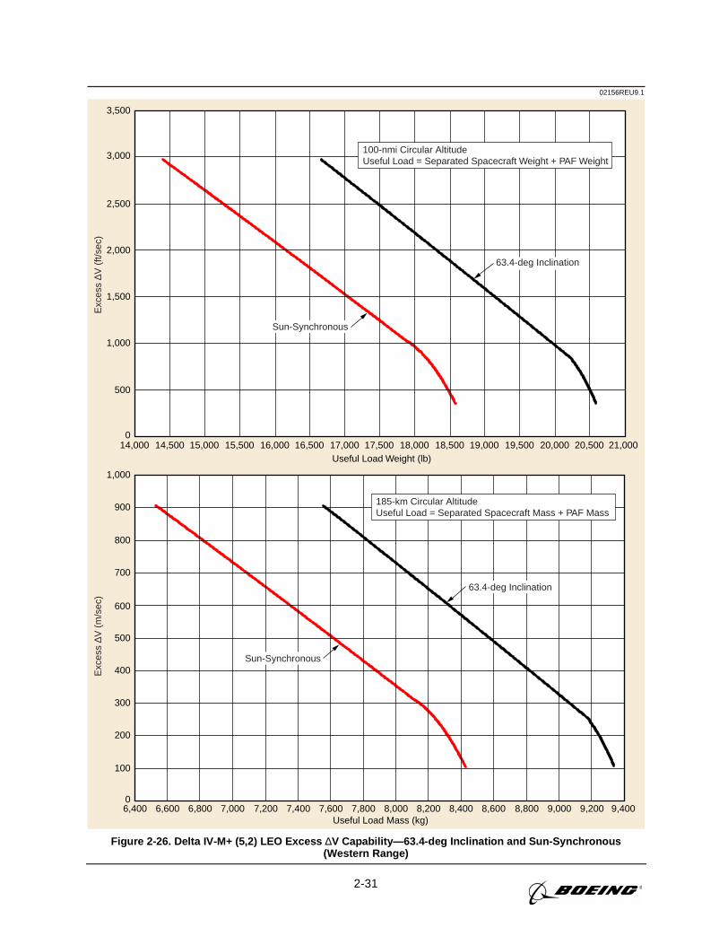
2-31
02156REU9.1E
xces
s ∆V
(m
/sec
)E
xces
s ∆V
(ft/
sec)
6,400 6,600 6,800 7,000 7,200 7,400 7,600 7,800 8,000 8,200 8,400 8,600 8,800 9,000 9,200 9,400Useful Load Mass (kg)
0
100
200
300
400
500
600
700
800
900
1,000
185-km Circular AltitudeUseful Load = Separated Spacecraft Mass + PAF Mass
14,000 14,500 15,000 15,500 16,000 16,500 17,000 17,500 18,000 18,500 19,000 19,500 20,000 20,500 21,000Useful Load Weight (lb)
0
500
1,000
1,500
2,000
2,500
3,000
3,500
100-nmi Circular AltitudeUseful Load = Separated Spacecraft Weight + PAF Weight
63.4-deg Inclination
Sun-Synchronous
63.4-deg Inclination
Sun-Synchronous
Figure 2-26. Delta IV-M+ (5,2) LEO Excess ∆V Capability—63.4-deg Inclination and Sun-Synchronous(Western Range)
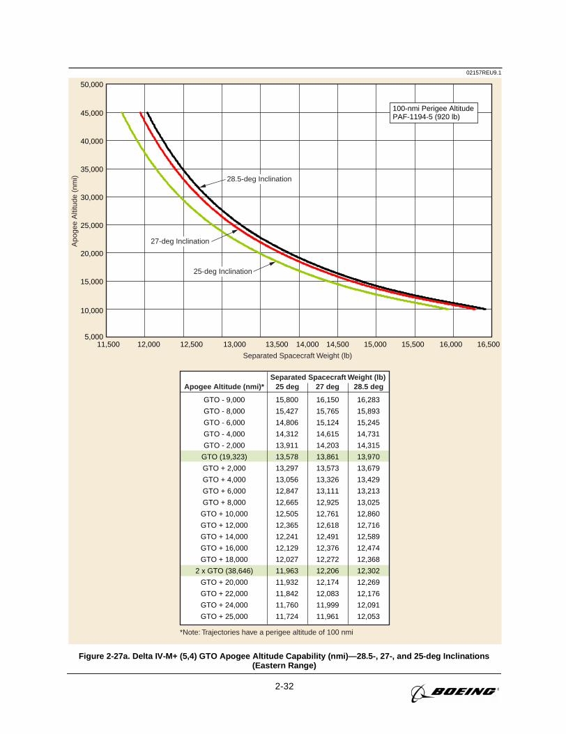
2-32
02157REU9.1A
poge
e A
ltitu
de (
nmi)
Separated Spacecraft Weight (lb)
*Note: Trajectories have a perigee altitude of 100 nmi
Separated Spacecraft Weight (lb)
100-nmi Perigee AltitudePAF-1194-5 (920 lb)
Apogee Altitude (nmi)* 25 deg 27 deg 28.5 deg
GTO - 9,000
GTO - 8,000
GTO - 6,000
GTO - 4,000
GTO - 2,000
GTO (19,323)
GTO + 2,000
GTO + 4,000
GTO + 6,000
GTO + 8,000
GTO + 10,000
GTO + 12,000
GTO + 14,000
GTO + 16,000
GTO + 18,000
2 x GTO (38,646)
GTO + 20,000
GTO + 22,000
GTO + 24,000
GTO + 25,000
15,800
15,427
14,806
14,312
13,911
13,578
13,297
13,056
12,847
12,665
12,505
12,365
12,241
12,129
12,027
11,963
11,932
11,842
11,760
11,724
16,150
15,765
15,124
14,615
14,203
13,861
13,573
13,326
13,111
12,925
12,761
12,618
12,491
12,376
12,272
12,206
12,174
12,083
11,999
11,961
16,283
15,893
15,245
14,731
14,315
13,970
13,679
13,429
13,213
13,025
12,860
12,716
12,589
12,474
12,368
12,302
12,269
12,176
12,091
12,053
5,000
10,000
15,000
20,000
25,000
30,000
35,000
40,000
45,000
50,000
28.5-deg Inclination
27-deg Inclination
25-deg Inclination
11,500 12,000 12,500 13,000 13,500 14,000 14,500 15,000 15,500 16,000 16,500
Figure 2-27a. Delta IV-M+ (5,4) GTO Apogee Altitude Capability (nmi)—28.5-, 27-, and 25-deg Inclinations(Eastern Range)
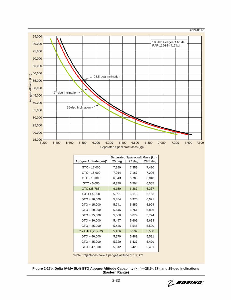
2-33
02158REU9.1A
poge
e A
ltitu
de (
km)
Separated Spacecraft Mass (kg)
*Note: Trajectories have a perigee altitude of 185 km
Separated Spacecraft Mass (kg)
185-km Perigee AltitudePAF-1194-5 (417 kg)
Apogee Altitude (km)* 25 deg 27 deg 28.5 deg
GTO - 17,000
GTO - 15,000
GTO - 10,000
GTO - 5,000
GTO (35,786)
GTO + 5,000
GTO + 10,000
GTO + 15,000
GTO + 20,000
GTO + 25,000
GTO + 30,000
GTO + 35,000
2 x GTO (71,752)
GTO + 40,000
GTO + 45,000
GTO + 47,000
7,199
7,014
6,643
6,370
6,159
5,991
5,854
5,741
5,646
5,566
5,497
5,436
5,426
5,379
5,329
5,312
7,359
7,167
6,785
6,504
6,287
6,115
5,975
5,859
5,761
5,679
5,609
5,546
5,537
5,489
5,437
5,420
7,420
7,226
6,840
6,555
6,337
6,163
6,021
5,904
5,806
5,724
5,653
5,590
5,580
5,531
5,479
5,461
28.5-deg Inclination
27-deg Inclination
25-deg Inclination
15,000
20,000
25,000
30,000
35,000
40,000
45,000
50,000
55,000
60,000
65,000
70,000
75,000
80,000
85,000
5,200 5,400 5,600 5,800 6,000 6,200 6,400 6,600 6,800 7,000 7,200 7,400 7,600
Figure 2-27b. Delta IV-M+ (5,4) GTO Apogee Altitude Capability (km)—28.5-, 27-, and 25-deg Inclinations(Eastern Range)

2-34
02159REU9.1E
xces
s ∆V
(ft/
sec)
Exc
ess
∆V (
m/s
ec)
Separated Spacecraft Weight (lb)
Separated Spacecraft Mass (kg)
11,500 12,000 12,500 13,000 13,500 14,000 14,500 15,000 15,500 16,000 16,5006,000
6,500
7,000
7,500
8,000
8,500
9,000
9,500
10,000
100-nmi Circular Parking Orbit at 28.9-deg InclinationPAF-1194-5 (920 lb)
1,900
2,000
2,100
2,200
2,300
2,400
2,500
2,600
2,700
2,800
2,900
3,000
185-km Circular Parking Orbit at 28.9-deg InclinationPAF-1194-5 (417 kg)
5,200 5,400 5,600 5,800 6,000 6,200 6,400 6,600 6,800 7,000 7,200 7,400 7,600
Figure 2-28. Delta IV-M+ (5,4) GTO Excess ∆V Capability—28.9-deg Inclination (Eastern Range)
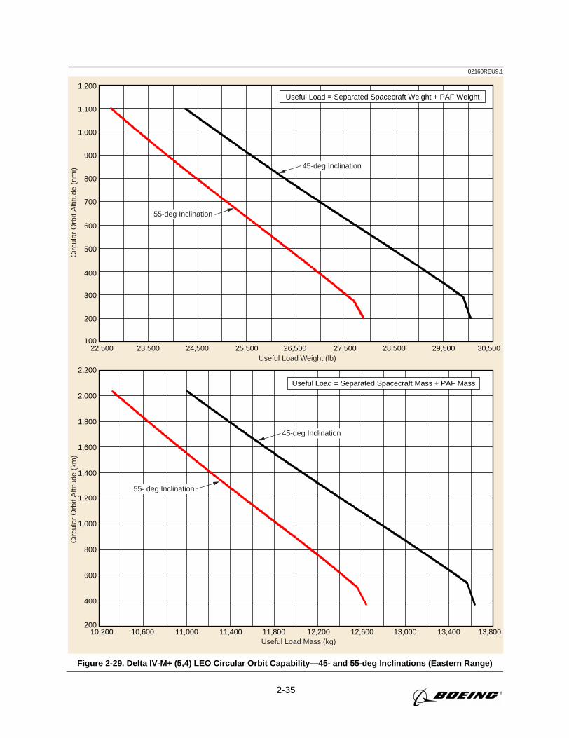
2-35
02160REU9.1C
ircul
ar O
rbit
Alti
tude
(nm
i)C
ircul
ar O
rbit
Alti
tude
(km
)
Useful Load Weight (lb)
Useful Load Mass (kg)
100
200
300
400
500
600
700
800
900
1,000
1,100
1,200
22,500 23,500 24,500 25,500 26,500 27,500 28,500 29,500 30,500
45-deg Inclination
55-deg Inclination
45-deg Inclination
55- deg Inclination
200
400
600
800
1,000
1,200
1,400
1,600
1,800
2,000
2,200
10,200 10,600 11,000 11,400 11,800 12,200 12,600 13,000 13,400 13,800
Useful Load = Separated Spacecraft Weight + PAF Weight
Useful Load = Separated Spacecraft Mass + PAF Mass
Figure 2-29. Delta IV-M+ (5,4) LEO Circular Orbit Capability—45- and 55-deg Inclinations (Eastern Range)
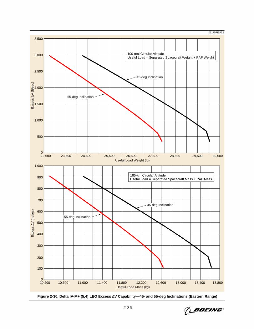
2-36
02175REU9.2E
xces
s ∆V
(ft/
sec)
Exc
ess
∆V (
m/s
ec)
Useful Load Weight (lb)
100-nmi Circular AltitudeUseful Load = Separated Spacecraft Weight + PAF Weight
45-deg Inclination
55-deg Inclination
Useful Load Mass (kg)
185-km Circular AltitudeUseful Load = Separated Spacecraft Mass + PAF Mass
45-deg Inclination
55-deg Inclination
0
500
1,000
1,500
2,000
2,500
3,000
3,500
22,500 23,500 24,500 25,500 26,500 27,500 28,500 29,500 30,500
0
100
200
300
400
500
600
700
800
900
1,000
10,200 10,600 11,000 11,400 11,800 12,200 12,600 13,000 13,400 13,800
Figure 2-30. Delta IV-M+ (5,4) LEO Excess ∆V Capability—45- and 55-deg Inclinations (Eastern Range)
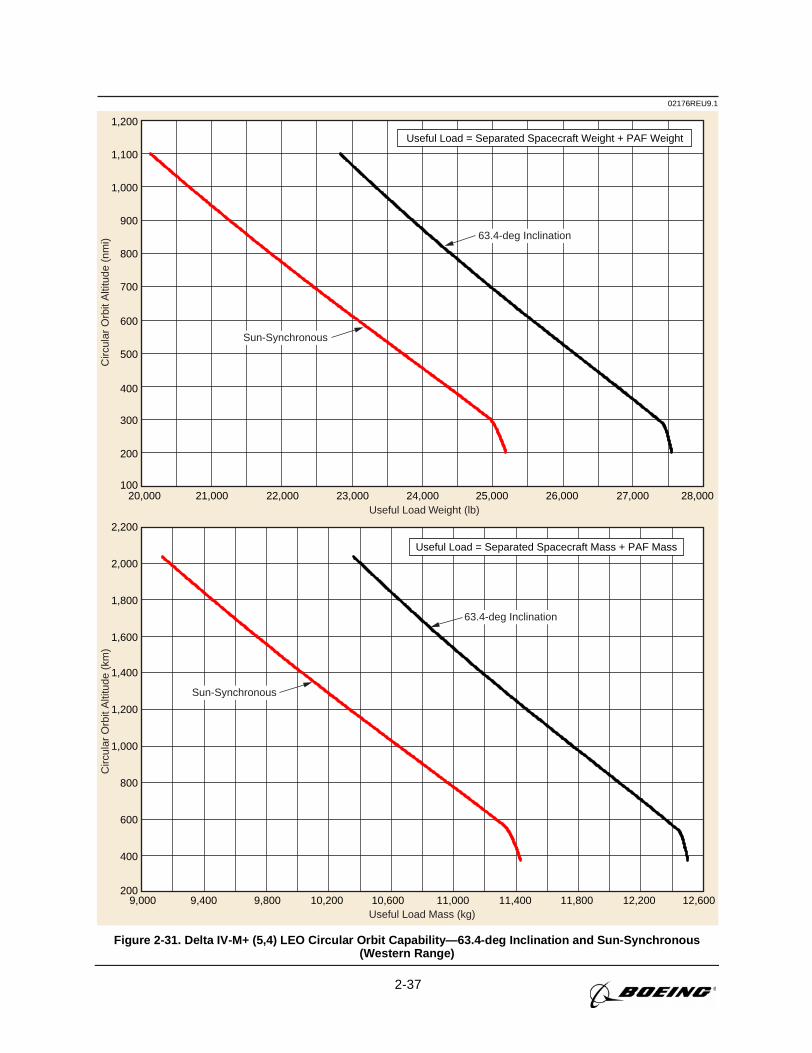
2-37
02176REU9.1C
ircul
ar O
rbit
Alti
tude
(nm
i)C
ircul
ar O
rbit
Alti
tude
(km
)
Useful Load Weight (lb)
Useful Load Mass (kg)
Useful Load = Separated Spacecraft Weight + PAF Weight
Useful Load = Separated Spacecraft Mass + PAF Mass
100
200
300
400
500
600
700
800
900
1,000
1,100
1,200
63.4-deg Inclination
Sun-Synchronous
63.4-deg Inclination
Sun-Synchronous
200
400
600
800
1,000
1,200
1,400
1,600
1,800
2,000
2,200
20,000 21,000 22,000 23,000 24,000 25,000 26,000 27,000 28,000
9,000 9,400 9,800 10,200 10,600 11,000 11,400 11,800 12,200 12,600
Figure 2-31. Delta IV-M+ (5,4) LEO Circular Orbit Capability—63.4-deg Inclination and Sun-Synchronous(Western Range)
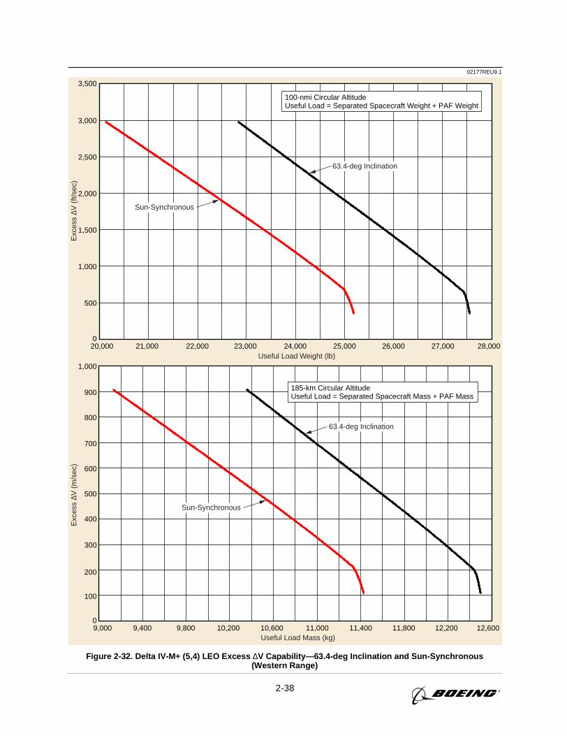
2-38
02177REU9.1E
xces
s ∆V
(ft/
sec)
Exc
ess
∆V (
m/s
ec)
Useful Load Weight (lb)
Useful Load Mass (kg)
100-nmi Circular AltitudeUseful Load = Separated Spacecraft Weight + PAF Weight
185-km Circular AltitudeUseful Load = Separated Spacecraft Mass + PAF Mass
63.4-deg Inclination
Sun-Synchronous
63.4-deg Inclination
Sun-Synchronous
0
500
1,000
1,500
2,000
2,500
3,000
3,500
0
100
200
300
400
500
600
700
800
900
1,000
20,000 21,000 22,000 23,000 24,000 25,000 26,000 27,000 28,000
9,000 9,400 9,800 10,200 10,600 11,000 11,400 11,800 12,200 12,600
Figure 2-32. Delta IV-M+ (5,4) LEO Excess ∆V Capability—63.4-deg Inclination and Sun-Synchronous(Western Range)
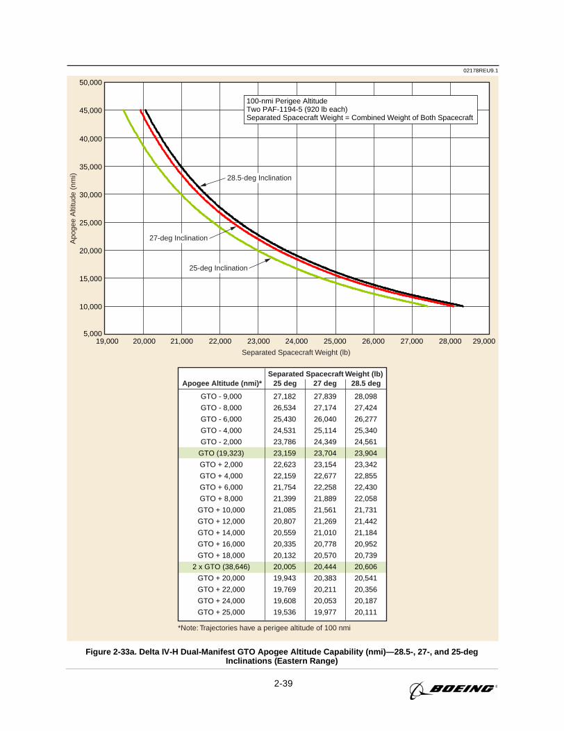
2-39
02178REU9.1A
poge
e A
ltitu
de (
nmi)
Separated Spacecraft Weight (lb)
*Note: Trajectories have a perigee altitude of 100 nmi
Separated Spacecraft Weight (lb)
100-nmi Perigee AltitudeTwo PAF-1194-5 (920 lb each)Separated Spacecraft Weight = Combined Weight of Both Spacecraft
Apogee Altitude (nmi)* 25 deg 27 deg 28.5 deg
GTO - 9,000
GTO - 8,000
GTO - 6,000
GTO - 4,000
GTO - 2,000
GTO (19,323)
GTO + 2,000
GTO + 4,000
GTO + 6,000
GTO + 8,000
GTO + 10,000
GTO + 12,000
GTO + 14,000
GTO + 16,000
GTO + 18,000
2 x GTO (38,646)
GTO + 20,000
GTO + 22,000
GTO + 24,000
GTO + 25,000
27,182
26,534
25,430
24,531
23,786
23,159
22,623
22,159
21,754
21,399
21,085
20,807
20,559
20,335
20,132
20,005
19,943
19,769
19,608
19,536
27,839
27,174
26,040
25,114
24,349
23,704
23,154
22,677
22,258
21,889
21,561
21,269
21,010
20,778
20,570
20,444
20,383
20,211
20,053
19,977
28,098
27,424
26,277
25,340
24,561
23,904
23,342
22,855
22,430
22,058
21,731
21,442
21,184
20,952
20,739
20,606
20,541
20,356
20,187
20,111
5,000
10,000
15,000
20,000
25,000
30,000
35,000
40,000
45,000
50,000
28.5-deg Inclination
27-deg Inclination
25-deg Inclination
19,000 20,000 21,000 22,000 23,000 24,000 25,000 26,000 27,000 28,000 29,000
Figure 2-33a. Delta IV-H Dual-Manifest GTO Apogee Altitude Capability (nmi)—28.5-, 27-, and 25-degInclinations (Eastern Range)
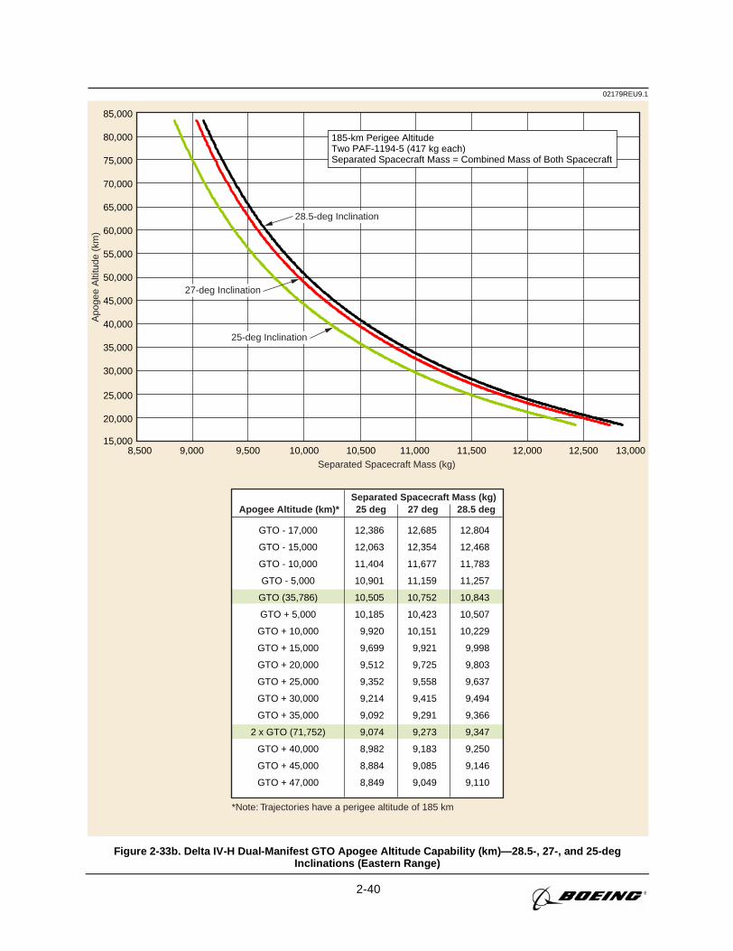
2-40
02179REU9.1A
poge
e A
ltitu
de (
km)
Separated Spacecraft Mass (kg)
*Note: Trajectories have a perigee altitude of 185 km
Separated Spacecraft Mass (kg)Apogee Altitude (km)* 25 deg 27 deg 28.5 deg
GTO - 17,000
GTO - 15,000
GTO - 10,000
GTO - 5,000
GTO (35,786)
GTO + 5,000
GTO + 10,000
GTO + 15,000
GTO + 20,000
GTO + 25,000
GTO + 30,000
GTO + 35,000
2 x GTO (71,752)
GTO + 40,000
GTO + 45,000
GTO + 47,000
12,386
12,063
11,404
10,901
10,505
10,185
9,920
9,699
9,512
9,352
9,214
9,092
9,074
8,982
8,884
8,849
12,685
12,354
11,677
11,159
10,752
10,423
10,151
9,921
9,725
9,558
9,415
9,291
9,273
9,183
9,085
9,049
12,804
12,468
11,783
11,257
10,843
10,507
10,229
9,998
9,803
9,637
9,494
9,366
9,347
9,250
9,146
9,110
28.5-deg Inclination
27-deg Inclination
25-deg Inclination
15,000
20,000
25,000
30,000
35,000
40,000
45,000
50,000
55,000
60,000
65,000
70,000
75,000
80,000
85,000
8,500 9,000 9,500 10,000 10,500 11,000 11,500 12,000 12,500 13,000
185-km Perigee AltitudeTwo PAF-1194-5 (417 kg each)Separated Spacecraft Mass = Combined Mass of Both Spacecraft
Figure 2-33b. Delta IV-H Dual-Manifest GTO Apogee Altitude Capability (km)—28.5-, 27-, and 25-degInclinations (Eastern Range)
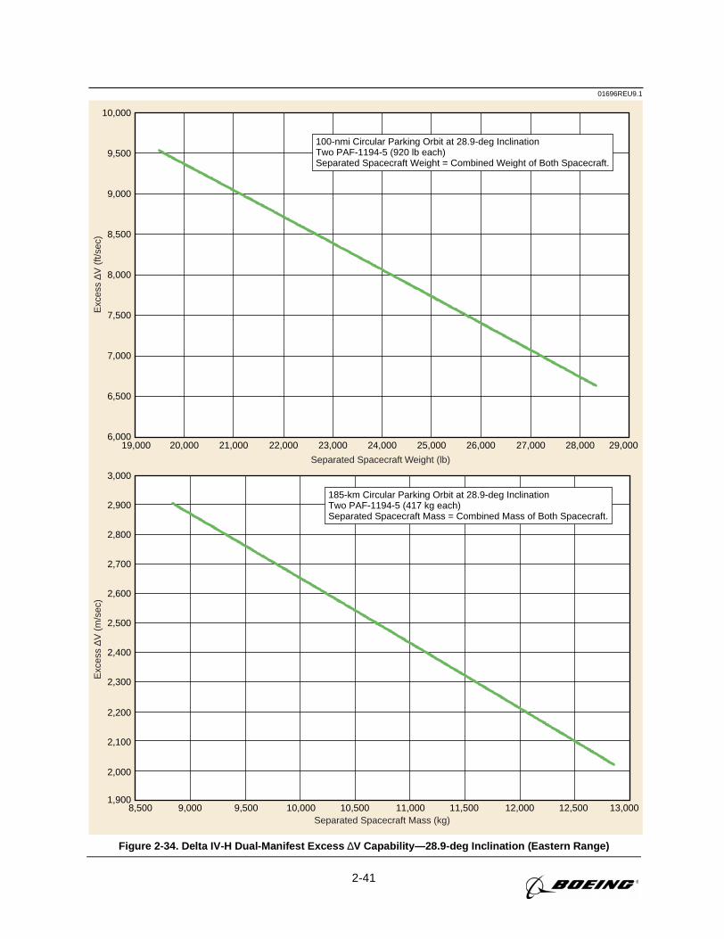
2-41
01696REU9.1E
xces
s ∆V
(ft/
sec)
Exc
ess
∆V (
m/s
ec)
Separated Spacecraft Weight (lb)
Separated Spacecraft Mass (kg)
6,000
6,500
7,000
7,500
8,000
8,500
9,000
9,500
10,000
1,900
2,000
2,100
2,200
2,300
2,400
2,500
2,600
2,700
2,800
2,900
3,000
100-nmi Circular Parking Orbit at 28.9-deg InclinationTwo PAF-1194-5 (920 lb each)Separated Spacecraft Weight = Combined Weight of Both Spacecraft.
185-km Circular Parking Orbit at 28.9-deg InclinationTwo PAF-1194-5 (417 kg each)Separated Spacecraft Mass = Combined Mass of Both Spacecraft.
19,000 20,000 21,000 22,000 23,000 24,000 25,000 26,000 27,000 28,000 29,000
8,500 9,000 9,500 10,000 10,500 11,000 11,500 12,000 12,500 13,000
Figure 2-34. Delta IV-H Dual-Manifest Excess ∆V Capability—28.9-deg Inclination (Eastern Range)
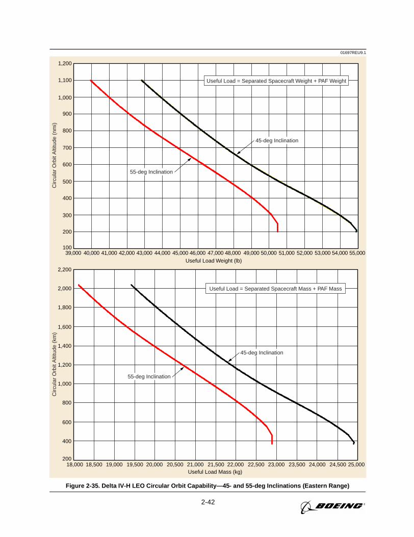
2-42
01697REU9.1C
ircul
ar O
rbit
Alti
tude
(km
)C
ircul
ar O
rbit
Alti
tude
(nm
i)
18,000 18,500 19,000 19,500 20,000 20,500 21,000 21,500 22,000 22,500 23,000 23,500 24,000 24,500 25,000Useful Load Mass (kg)
200
400
600
800
1,000
1,200
1,400
1,600
1,800
2,000
2,200
Useful Load = Separated Spacecraft Mass + PAF Mass
39,000 41,000 42,00040,000 43,000 44,000 45,000 46,000 47,000 48,000 49,000 50,000 51,000 52,000 53,000 54,000 55,000Useful Load Weight (lb)
100
200
300
400
500
600
700
800
900
1,000
1,100
1,200
Useful Load = Separated Spacecraft Weight + PAF Weight
45-deg Inclination
55-deg Inclination
45-deg Inclination
55-deg Inclination
Figure 2-35. Delta IV-H LEO Circular Orbit Capability—45- and 55-deg Inclinations (Eastern Range)
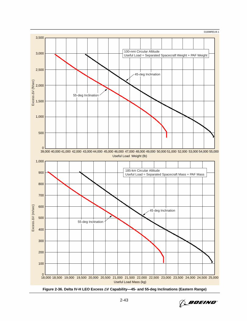
2-43
01698REU9.1E
xces
s ∆V
(m
/sec
)E
xces
s ∆V
(ft/
sec)
18,000 18,500 19,000 19,500 20,000 20,500 21,000 21,500 22,000 22,500 23,000 23,500 24,000 24,500 25,000Useful Load Mass (kg)
0
100
200
300
400
500
600
700
800
900
1,000
185-km Circular AltitudeUseful Load = Separated Spacecraft Mass + PAF Mass
39,000 40,000 41,000 42,000 43,000 44,000 45,000 46,000 47,000 48,000 49,000 50,000 51,000 52,000 53,000 54,000 55,000Useful Load Weight (lb)
0
500
1,000
1,500
2,000
2,500
3,000
3,500
100-nmi Circular AltitudeUseful Load = Separated Spacecraft Weight + PAF Weight
45-deg Inclination
55-deg Inclination
45-deg Inclination
55-deg Inclination
Figure 2-36. Delta IV-H LEO Excess ∆V Capability—45- and 55-deg Inclinations (Eastern Range)
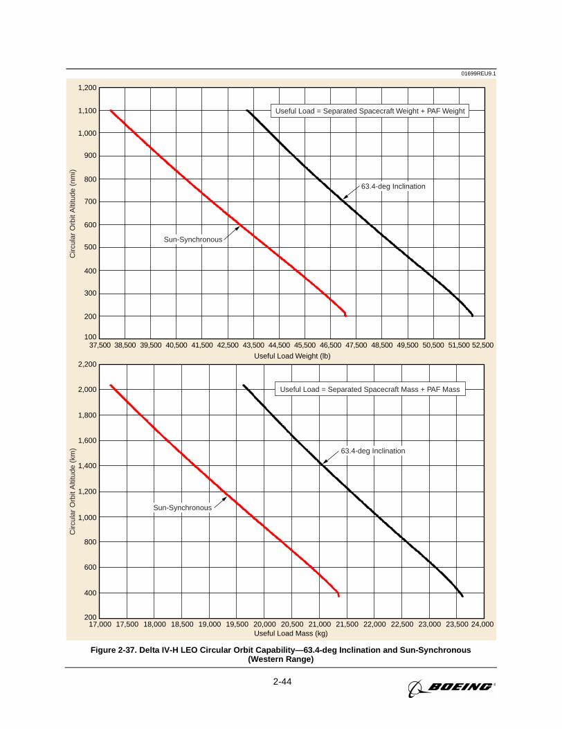
2-44
01699REU9.1C
ircul
ar O
rbit
Alti
tude
(km
)C
ircul
ar O
rbit
Alti
tude
(nm
i)
17,000 17,500 18,000 18,500 19,000 19,500 20,000 20,500 21,000 21,500 22,000 22,500 23,000 23,500 24,000Useful Load Mass (kg)
200
400
600
800
1,000
1,200
1,400
1,600
1,800
2,000
2,200
Useful Load = Separated Spacecraft Mass + PAF Mass
37,500 38,500 39,500 40,500 41,500 42,500 43,500 44,500 45,500 46,500 47,500 48,500 49,500 50,500 51,500 52,500
Useful Load Weight (lb)
100
200
300
400
500
600
700
800
900
1,000
1,100
1,200
Useful Load = Separated Spacecraft Weight + PAF Weight
63.4-deg Inclination
Sun-Synchronous
63.4-deg Inclination
Sun-Synchronous
Figure 2-37. Delta IV-H LEO Circular Orbit Capability—63.4-deg Inclination and Sun-Synchronous(Western Range)
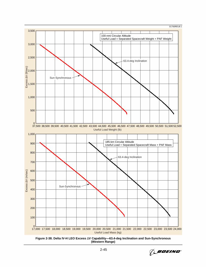
2-45
01700REU9.1E
xces
s ∆V
(ft/
sec)
Exc
ess
∆V (
m/s
ec)
Useful Load Weight (lb)
Useful Load Mass (kg)
100-nmi Circular AltitudeUseful Load = Separated Spacecraft Weight + PAF Weight
185-km Circular AltitudeUseful Load = Separated Spacecraft Mass + PAF Mass
63.4-deg Inclination
Sun-Synchronous
63.4-deg Inclination
Sun-Synchronous
0
500
1,000
1,500
2,000
2,500
3,000
3,500
0
100
200
300
400
500
600
700
800
900
1,000
37,500 38,500 39,500 40,500 41,500 42,500 43,500 44,500 45,500 46,500 47,500 48,500 49,500 50,500 51,500 52,500
17,000 17,500 18,000 18,500 19,000 19,500 20,000 20,500 21,000 21,500 22,000 22,500 23,000 23,500 24,000
Figure 2-38. Delta IV-H LEO Excess ∆V Capability—63.4-deg Inclination and Sun-Synchronous(Western Range)
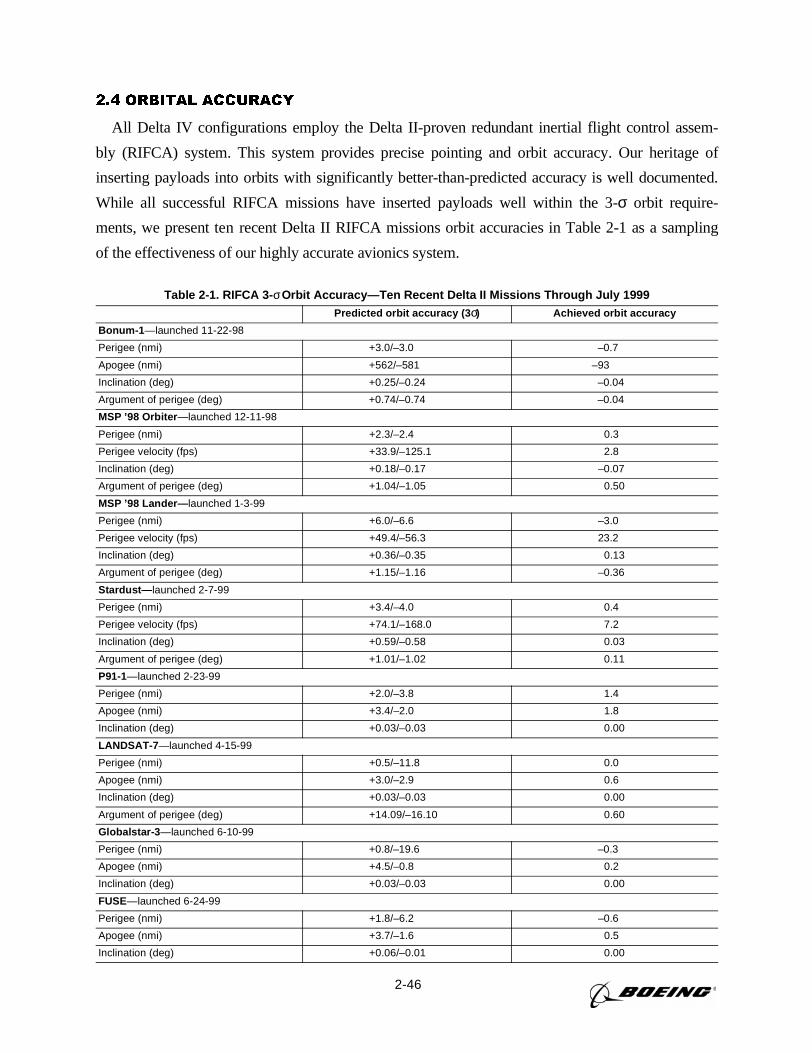
2-46
2.4 ORBITAL ACCURACY
All Delta IV configurations employ the Delta II-proven redundant inertial flight control assem-
bly (RIFCA) system. This system provides precise pointing and orbit accuracy. Our heritage of
inserting payloads into orbits with significantly better-than-predicted accuracy is well documented.
While all successful RIFCA missions have inserted payloads well within the 3-σ orbit require-
ments, we present ten recent Delta II RIFCA missions orbit accuracies in Table 2-1 as a sampling
of the effectiveness of our highly accurate avionics system.
Table 2-1. RIFCA 3- σOrbit Accuracy—Ten Recent Delta II Missions Through July 1999Predicted orbit accuracy (3 σ) Achieved orbit accuracy
Bonum-1 —launched 11-22-98
Perigee (nmi) +3.0/–3.0 –0.7
Apogee (nmi) +562/–581 –93
Inclination (deg) +0.25/–0.24 –0.04
Argument of perigee (deg) +0.74/–0.74 –0.04
MSP ’98 Orbiter —launched 12-11-98
Perigee (nmi) +2.3/–2.4 0.3
Perigee velocity (fps) +33.9/–125.1 2.8
Inclination (deg) +0.18/–0.17 –0.07
Argument of perigee (deg) +1.04/–1.05 0.50
MSP ’98 Lander— launched 1-3-99
Perigee (nmi) +6.0/–6.6 –3.0
Perigee velocity (fps) +49.4/–56.3 23.2
Inclination (deg) +0.36/–0.35 0.13
Argument of perigee (deg) +1.15/–1.16 –0.36
Stardust— launched 2-7-99
Perigee (nmi) +3.4/–4.0 0.4
Perigee velocity (fps) +74.1/–168.0 7.2
Inclination (deg) +0.59/–0.58 0.03
Argument of perigee (deg) +1.01/–1.02 0.11
P91-1—launched 2-23-99
Perigee (nmi) +2.0/–3.8 1.4
Apogee (nmi) +3.4/–2.0 1.8
Inclination (deg) +0.03/–0.03 0.00
LANDSAT-7 —launched 4-15-99
Perigee (nmi) +0.5/–11.8 0.0
Apogee (nmi) +3.0/–2.9 0.6
Inclination (deg) +0.03/–0.03 0.00
Argument of perigee (deg) +14.09/–16.10 0.60
Globalstar-3 —launched 6-10-99
Perigee (nmi) +0.8/–19.6 –0.3
Apogee (nmi) +4.5/–0.8 0.2
Inclination (deg) +0.03/–0.03 0.00
FUSE—launched 6-24-99
Perigee (nmi) +1.8/–6.2 –0.6
Apogee (nmi) +3.7/–1.6 0.5
Inclination (deg) +0.06/–0.01 0.00
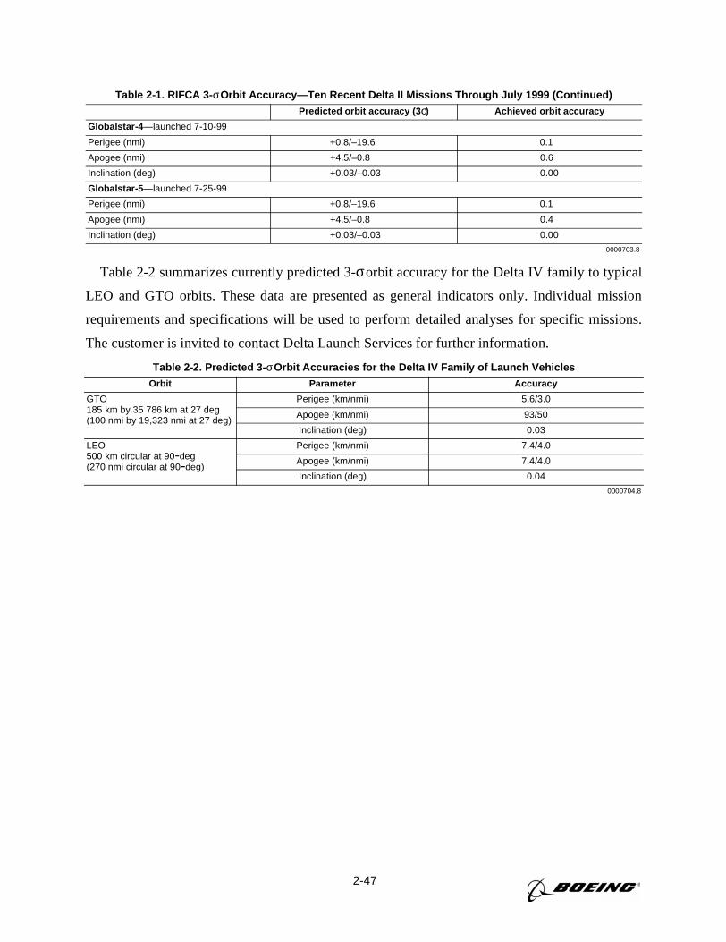
2-47
Table 2-2 summarizes currently predicted 3-σorbit accuracy for the Delta IV family to typical
LEO and GTO orbits. These data are presented as general indicators only. Individual mission
requirements and specifications will be used to perform detailed analyses for specific missions.
The customer is invited to contact Delta Launch Services for further information.
Table 2-1. RIFCA 3- σOrbit Accuracy—Ten Recent Delta II Missions Through July 1999 (Continued)Predicted orbit accuracy (3 σ) Achieved orbit accuracy
Globalstar-4 —launched 7-10-99
Perigee (nmi) +0.8/–19.6 0.1
Apogee (nmi) +4.5/–0.8 0.6
Inclination (deg) +0.03/–0.03 0.00
Globalstar-5 —launched 7-25-99
Perigee (nmi) +0.8/–19.6 0.1
Apogee (nmi) +4.5/–0.8 0.4
Inclination (deg) +0.03/–0.03 0.00
0000703.8
Table 2-2. Predicted 3- σOrbit Accuracies for the Delta IV Family of Launch VehiclesOrbit Parameter Accuracy
GTO185 km by 35 786 km at 27 deg(100 nmi by 19,323 nmi at 27 deg)
Perigee (km/nmi) 5.6/3.0
Apogee (km/nmi) 93/50
Inclination (deg) 0.03
LEO500 km circular at 90-deg(270 nmi circular at 90-deg)
Perigee (km/nmi) 7.4/4.0
Apogee (km/nmi) 7.4/4.0
Inclination (deg) 0.04
0000704.8
3-1
Section 3
PAYLOAD FAIRINGS
The payload launched on a Delta IV Medium, Delta IV Medium-Plus, or Delta IV Heavy launch vehi-
cle is protected by fairings that shield it from the external environment and contamination during the pre-
launch and ascent phases. The Delta IV launch system uses a wide variety of heritage-based fairings to
meet the broad needs of our customers (Figure 3-1). Fairings are jettisoned early during either first- or
second-stage powered flight when an acceptable free molecular heating rate is reached (Section 2.3). A
general discussion of the Delta IV fairings is presented in Section 3.1. Detailed fairing descriptions and
envelopes are given in Sections 3.2 and3.3.
3.1 GENERAL DESCRIPTION
The envelopes presented in the following text and illustrations for composite fairings define the
maximum allowable static dimensions (seeSection 4) of the payload (including manufacturing tol-
erances) relative to the payload/attach fitting interface. If dimensions are maintained within these
envelopes, there will be no contact of the payload with the fairing during flight as long as the pay-
load’s frequency and structural stiffness characteristics are in accordance with the guidelines spec-
ified in Section 4.2.3. Payload envelopes include allowances for relative deflections between the
launch vehicle and payload. Also included are launch vehicle manufacturing tolerances and the
thickness (including billowing) of the acoustic blankets that are installed on the interior of the fair-
ing. The available blanket configurations are described inTable 3-1.
Clearance layouts and analyses are performed and, if necessary, critical clearances are measured
after the fairing is installed to ensure positive clearance during flight. To facilitate this, the payload
description must include an accurate definition of the physical location of all points on the payload
that are within 51 mm (2 in.) of the allowable envelope. (Refer toSection 8, Payload Integration.)
The dimensions must include the maximum payload manufacturing tolerances (and, if applicable,
blanket billowing).
An air-conditioning inlet door on the fairing provides a controlled environment for the encapsu-
lated payload while on the launch stand (Section 4.1.1). A GN2 purge system can be incorporated
to provide continuous dry nitrogen to the payload until liftoff.
Payload contamination is minimized by cleaning the fairing in a class 100,000 clean room prior
to shipment to the field site. Special cleaning of the fairing with inspection using an ultraviolet (UV)
light is available on request. (SeeTable 4-4andSection 4.1.5for a description of cleanliness levels.)
3.2 4-M AND 5-M-DIA COMPOSITE PAYLOAD FAIRING
The 4-m-dia by 11.7-m (38.5-ft)-long composite fairing is the standard fairing used on the
Delta IV-M and Delta IV-M+ (4,2) launch vehicles. The 5-m-dia by 14.3-m (47-ft)-long
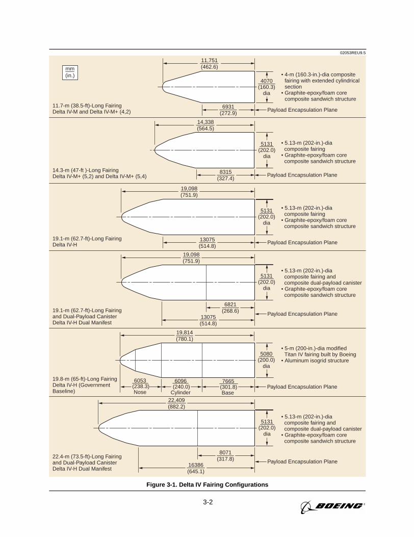
3-2
02053REU9.5
mm(in.)
• 5.13-m (202-in.)-dia composite fairing• Graphite-epoxy/foam core composite sandwich structure
• 5.13-m (202-in.)-dia composite fairing and composite dual-payload canister• Graphite-epoxy/foam core composite sandwich structure
• 5.13-m (202-in.)-dia composite fairing and composite dual-payload canister• Graphite-epoxy/foam core composite sandwich structure
• 5.13-m (202-in.)-dia composite fairing• Graphite-epoxy/foam core composite sandwich structure
• 4-m (160.3-in.)-dia compositefairing with extended cylindricalsection
• Graphite-epoxy/foam corecomposite sandwich structure
19.1-m (62.7-ft)-Long FairingDelta IV-H
11.7-m (38.5-ft)-Long FairingDelta IV-M and Delta IV-M+ (4,2)
14.3-m (47-ft )-Long FairingDelta IV-M+ (5,2) and Delta IV-M+ (5,4)
19.1-m (62.7-ft)-Long Fairingand Dual-Payload CanisterDelta IV-H Dual Manifest
22.4-m (73.5-ft)-Long Fairingand Dual-Payload CanisterDelta IV-H Dual Manifest
14,338(564.5)
11,751(462.6)
6931(272.9)
8315(327.4)
5131(202.0)
dia
4070(160.3)
dia
• 5-m (200-in.)-dia modifiedTitan IV fairing built by Boeing
• Aluminum isogrid structure
19.8-m (65-ft)-Long FairingDelta IV-H (GovernmentBaseline)
7665 (301.8)
Base (240.0)Cylinder
6096 (238.3)
Nose
6053
19,814(780.1)
5080(200.0)
dia
19,098(751.9)
13075(514.8)
5131(202.0)
dia
22,409(882.2)
16386(645.1)
8071(317.8)
5131(202.0)
dia
19,098(751.9)
13075(514.8)
5131(202.0)
dia
6821(268.6)
Payload Encapsulation Plane
Payload Encapsulation Plane
Payload Encapsulation Plane
Payload Encapsulation Plane
Payload Encapsulation Plane
Payload Encapsulation Plane
Figure 3-1. Delta IV Fairing Configurations
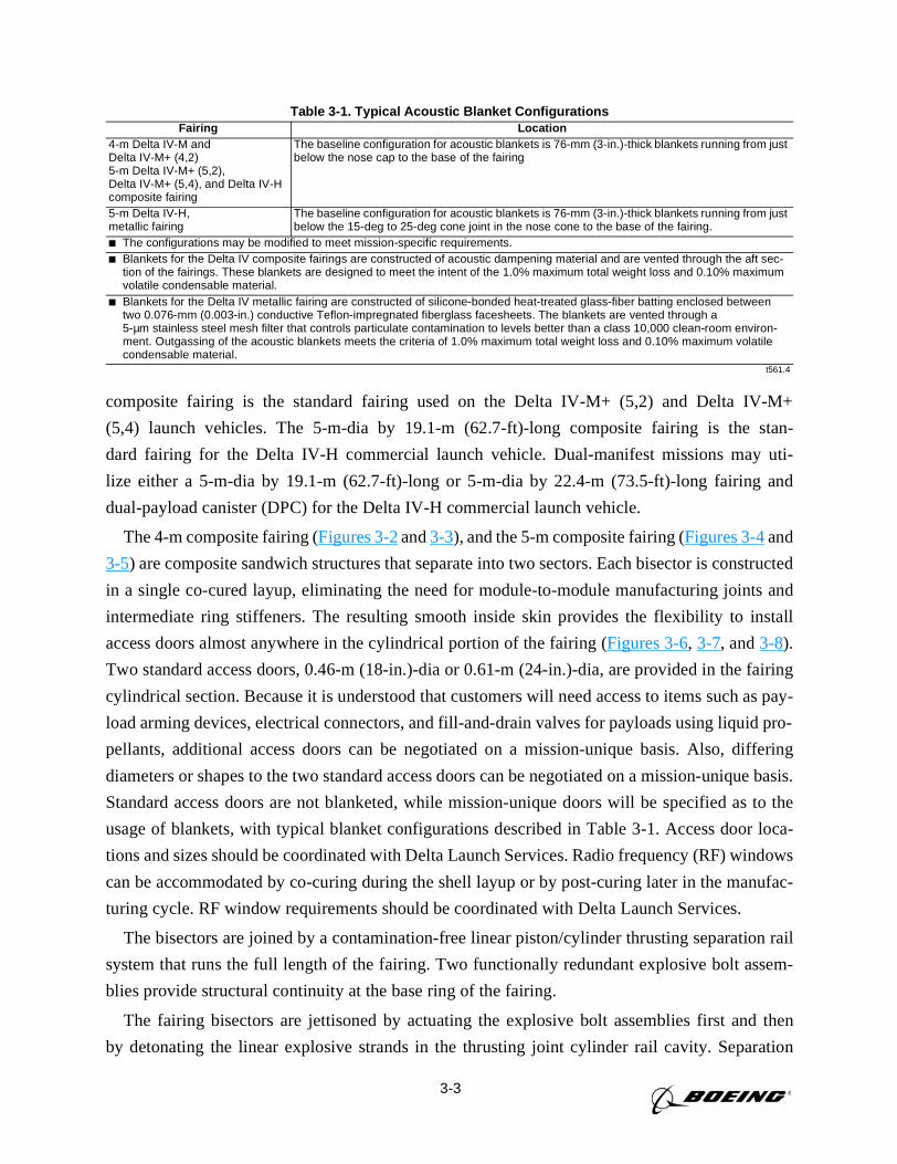
3-3
composite fairing is the standard fairing used on the Delta IV-M+ (5,2) and Delta IV-M+
(5,4) launch vehicles. The 5-m-dia by 19.1-m (62.7-ft)-long composite fairing is the stan-
dard fairing for the Delta IV-H commercial launch vehicle. Dual-manifest missions may uti-
lize either a 5-m-dia by 19.1-m (62.7-ft)-long or 5-m-dia by 22.4-m (73.5-ft)-long fairing and
dual-payload canister (DPC) for the Delta IV-H commercial launch vehicle.
The 4-m composite fairing (Figures 3-2and3-3), and the 5-m composite fairing (Figures 3-4and
3-5) are composite sandwich structures that separate into two sectors. Each bisector is constructed
in a single co-cured layup, eliminating the need for module-to-module manufacturing joints and
intermediate ring stiffeners. The resulting smooth inside skin provides the flexibility to install
access doors almost anywhere in the cylindrical portion of the fairing (Figures 3-6, 3-7, and3-8).
Two standard access doors, 0.46-m (18-in.)-dia or 0.61-m (24-in.)-dia, are provided in the fairing
cylindrical section. Because it is understood that customers will need access to items such as pay-
load arming devices, electrical connectors, and fill-and-drain valves for payloads using liquid pro-
pellants, additional access doors can be negotiated on a mission-unique basis. Also, differing
diameters or shapes to the two standard access doors can be negotiated on a mission-unique basis.
Standard access doors are not blanketed, while mission-unique doors will be specified as to the
usage of blankets, with typical blanket configurations described in Table 3-1. Access door loca-
tions and sizes should be coordinated with Delta Launch Services. Radio frequency (RF) windows
can be accommodated by co-curing during the shell layup or by post-curing later in the manufac-
turing cycle. RF window requirements should be coordinated with Delta Launch Services.
The bisectors are joined by a contamination-free linear piston/cylinder thrusting separation rail
system that runs the full length of the fairing. Two functionally redundant explosive bolt assem-
blies provide structural continuity at the base ring of the fairing.
The fairing bisectors are jettisoned by actuating the explosive bolt assemblies first and then
by detonating the linear explosive strands in the thrusting joint cylinder rail cavity. Separation
Table 3-1. Typical Acoustic Blanket ConfigurationsFairing Location
4-m Delta IV-M andDelta IV-M+ (4,2)5-m Delta IV-M+ (5,2),Delta IV-M+ (5,4), and Delta IV-Hcomposite fairing
The baseline configuration for acoustic blankets is 76-mm (3-in.)-thick blankets running from justbelow the nose cap to the base of the fairing
5-m Delta IV-H,metallic fairing
The baseline configuration for acoustic blankets is 76-mm (3-in.)-thick blankets running from justbelow the 15-deg to 25-deg cone joint in the nose cone to the base of the fairing.
The configurations may be modified to meet mission-specific requirements. Blankets for the Delta IV composite fairings are constructed of acoustic dampening material and are vented through the aft sec-
tion of the fairings. These blankets are designed to meet the intent of the 1.0% maximum total weight loss and 0.10% maximumvolatile condensable material.
Blankets for the Delta IV metallic fairing are constructed of silicone-bonded heat-treated glass-fiber batting enclosed betweentwo 0.076-mm (0.003-in.) conductive Teflon-impregnated fiberglass facesheets. The blankets are vented through a5-µm stainless steel mesh filter that controls particulate contamination to levels better than a class 10,000 clean-room environ-ment. Outgassing of the acoustic blankets meets the criteria of 1.0% maximum total weight loss and 0.10% maximum volatilecondensable material.
t561.4
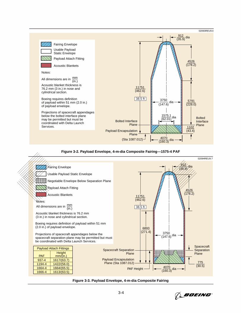
3-4
02093REU9.6
4070(160.3)
11751(462.6)
5791(228.0)
1102(43.4)
4526(178.2)
912(35.9)
Payload EncapsulationPlane
Bolted InterfacePlane
mm(in.)
Usable PayloadStatic Envelope
Fairing Envelope
All dimensions are in
Payload Attach Fitting
Acoustic blanket thickness is76.2 mm (3 in.) in nose andcylindrical section.
Boeing requires definition of payload within 51 mm (2.0 in.) of payload envelope.
Projections of spacecraft appendagesbelow the bolted interface planemay be permitted but must becoordinated with Delta LaunchServices.
Acoustic Blankets
Notes:
dia
1575.1(62.01) Bolted
InterfacePlane
3750(147.6)
dia
dia
dia
38.5 ft
(Sta 1087.012)
Figure 3-2. Payload Envelope, 4-m-dia Composite Fairing—1575-4 PAF
02094REU9.7
912(35.9)
4526(178.2)
6893(271.4)
11751(462.6)
775(30.5)
mm(in.)
Usable Payload Static Envelope
Negotiable Envelope Below Separation Plane
Fairing Envelope
All dimensions are in
Payload Attach Fitting
Boeing requires definition of payload within 51 mm(2.0 in.) of payload envelope.
Projections of spacecraft appendages below the spacecraft separation plane may be permitted but mustbe coordinated with Delta Launch Services.
Acoustic Blankets
Notes:
SpacecraftSeparationPlane
Payload EncapsulationPlane (Sta 1087.012)
Spacecraft SeparationPlane
PAF Height
3750(147.6) dia
dia
4070(160.3)
dia
38.5 ft
Acoustic blanket thickness is 76.2 mm(3 in.) in nose and cylindrical section.
937-41194-41664-41666-4
1617/(63.7)1422/(56.0)1664/(65.5)1613/(63.5)
PAFHeight
mm/(in.)
Payload Attach Fittings
Figure 3-3. Payload Envelope, 4-m-dia Composite Fairing
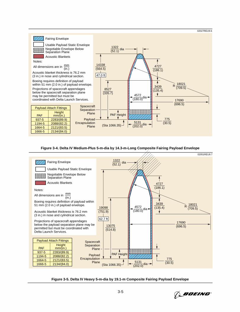
3-5
02027REU9.6
mm(in.)
Usable Payload Static Envelope
Fairing Envelope
All dimensions are in
Acoustic blanket thickness is 76.2 mm(3 in.) in nose and cylindrical section.
Projections of spacecraft appendagesbelow the spacecraft separation planemay be permitted but must becoordinated with Delta Launch Services.
Boeing requires definition of payloadwithin 51 mm (2.0 in.) of payload envelope.
Acoustic Blankets
Notes:
5131(202.0)
PAF Height
PayloadEncapsulation
Plane
SpacecraftSeparation
Plane
4572(180.0)
1322(52.1)
dia
dia
dia
8527(335.7)
14338(564.5)
47.0 ft
17690(696.5)
4727(186.1)
3439(135.4)
18021(709.5)
R
Negotiable Envelope BelowSeparation Plane
(Sta 1066.35)
775(30.5)
937-51194-51664-51666-5
2283/(89.9)2088/(82.2)2121/(83.5)2134/(84.0)
PAFHeight
mm/(in.)
Payload Attach Fittings
Figure 3-4. Delta IV Medium-Plus 5-m-dia by 14.3-m-Long Composite Fairing Payload Envelope
02051REU9.7
mm(in.)
Usable Payload Static Envelope
Negotiable Envelope BelowSeparation Plane
Fairing Envelope
All dimensions are in
Boeing requires definition of payload within51 mm (2.0 in.) of payload envelope.
Acoustic blanket thickness is 76.2 mm(3 in.) in nose and cylindrical section.
Projections of spacecraft appendagesbelow the payload separation plane may bepermitted but must be coordinated withDelta Launch Services.
Acoustic Blankets
Notes:
937-51194-51664-51666-5
2283/(89.9)2088/(82.2)2121/(83.5)2134/(84.0)
PAFHeight
mm/(in.)
Payload Attach Fittings
5131(202.0)
PAF Height
dia
1322(52.1)
dia
13075(514.8)
19098(751.9)
4572(180.0)
dia
PayloadEncapsulation
Plane(Sta 1066.35)
SpacecraftSeparation
Plane
62.7 ft
18021(709.5)
17690(696.5)
775(30.5)
3439(135.4)
4727(186.1)
R
Figure 3-5. Delta IV Heavy 5-m-dia by 19.1-m Composite Fairing Payload Envelope
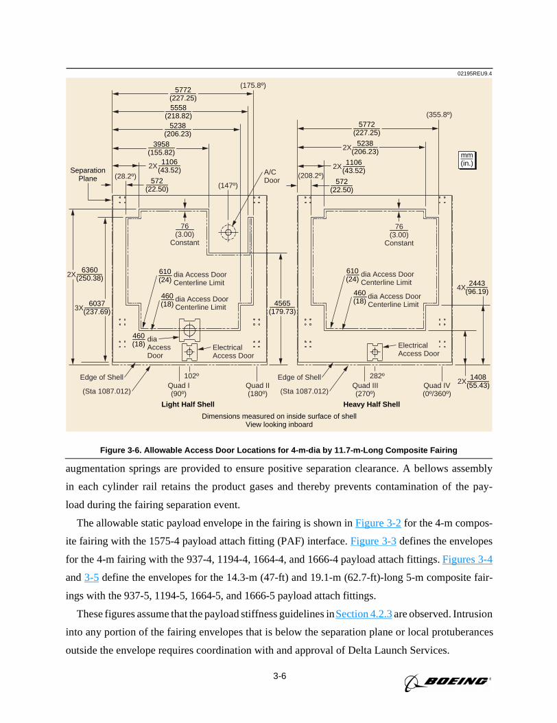
3-6
augmentation springs are provided to ensure positive separation clearance. A bellows assembly
in each cylinder rail retains the product gases and thereby prevents contamination of the pay-
load during the fairing separation event.
The allowable static payload envelope in the fairing is shown inFigure 3-2for the 4-m compos-
ite fairing with the 1575-4 payload attach fitting (PAF) interface.Figure 3-3defines the envelopes
for the 4-m fairing with the 937-4, 1194-4, 1664-4, and 1666-4 payload attach fittings.Figures 3-4
and3-5 define the envelopes for the 14.3-m (47-ft) and 19.1-m (62.7-ft)-long 5-m composite fair-
ings with the 937-5, 1194-5, 1664-5, and 1666-5 payload attach fittings.
These figures assume that the payload stiffness guidelines inSection 4.2.3are observed. Intrusion
into any portion of the fairing envelopes that is below the separation plane or local protuberances
outside the envelope requires coordination with and approval of Delta Launch Services.
Dimensions measured on inside surface of shellView looking inboard
SeparationPlane
Light Half Shell Heavy Half Shell
02195REU9.4
2X
102º
(147º)(208.2º)
(175.8º)
A/CDoor
(355.8º)
(28.2º)
dia Access DoorCenterline Limit
Electrical Access Door
Electrical Access Door
dia Access DoorCenterline Limit
dia Access DoorCenterline Limit
diaAccessDoor
(Sta 1087.012)
dia Access DoorCenterline Limit
Edge of Shell 282º
76(3.00)
Constant
(Sta 1087.012)
Edge of ShellQuad I(90º)
Quad II(180º)
Quad III(270º)
Quad IV(0º/360º)
mm(in.)
5772(227.25)
5772(227.25)
5238(206.23)
3958(155.82)
5238(206.23)
4565(179.73)
76(3.00)
Constant
2X
4X 2443
(96.19)
1408(55.43)
6037(237.69)
6360(250.38)
3X
2X
5558(218.82)
2X 1106(43.52)
572(22.50)
572(22.50)
610(24)
460(18)
610(24)
460(18)
460(18)
2X 1106(43.52)
Figure 3-6. Allowable Access Door Locations for 4-m-dia by 11.7-m-Long Composite Fairing
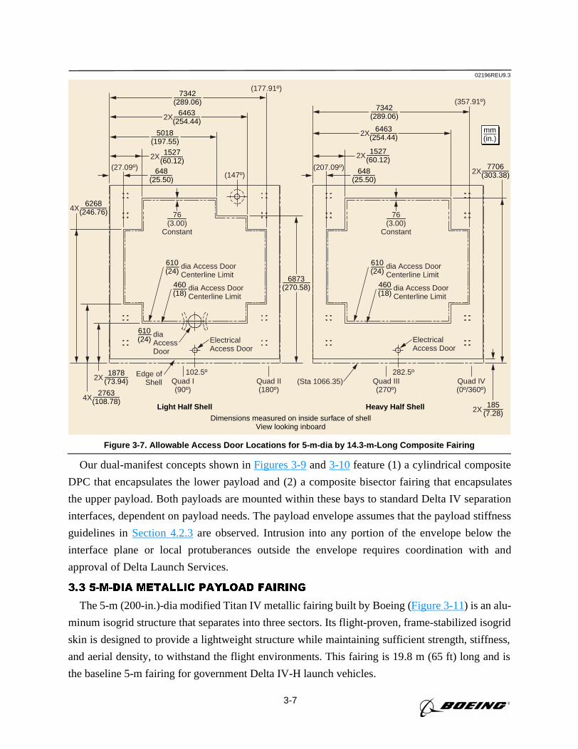
3-7
Our dual-manifest concepts shown inFigures 3-9and3-10feature (1) a cylindrical composite
DPC that encapsulates the lower payload and (2) a composite bisector fairing that encapsulates
the upper payload. Both payloads are mounted within these bays to standard Delta IV separation
interfaces, dependent on payload needs. The payload envelope assumes that the payload stiffness
guidelines inSection 4.2.3are observed. Intrusion into any portion of the envelope below the
interface plane or local protuberances outside the envelope requires coordination with and
approval of Delta Launch Services.
3.3 5-M-DIA METALLIC PAYLOAD FAIRING
The 5-m (200-in.)-dia modified Titan IV metallic fairing built by Boeing (Figure 3-11) is an alu-
minum isogrid structure that separates into three sectors. Its flight-proven, frame-stabilized isogrid
skin is designed to provide a lightweight structure while maintaining sufficient strength, stiffness,
and aerial density, to withstand the flight environments. This fairing is 19.8 m (65 ft) long and is
the baseline 5-m fairing for government Delta IV-H launch vehicles.
Dimensions measured on inside surface of shellView looking inboard
Light Half Shell Heavy Half Shell
02196REU9.3
(147º)(27.09º)
Edge ofShell (Sta 1066.35)
(207.09º)
(177.91º)
(357.91º)
102.5º 282.5ºQuad I(90º)
Quad II(180º)
Quad III(270º)
Quad IV(0º/360º)
dia Access DoorCenterline Limit
dia Access DoorCenterline Limit
Electrical Access Door
Electrical Access Door
6873(270.58)
2X 7706
(303.38)
2X 185
(7.28)
mm(in.)
4X 6268
(246.76)
4X 2763
(108.78)
76(3.00)
Constant
76(3.00)
Constant
2X 1878
(73.94)
648(25.50)
648(25.50)
2X 1527(60.12)
2X 1527(60.12)
5018(197.55)
7342(289.06)
6463(254.44)2X
7342(289.06)
6463(254.44)2X
610(24)
460(18)
dia Access DoorCenterline Limit
dia Access DoorCenterline Limit
610(24)
diaAccessDoor
610(24)
460(18)
Figure 3-7. Allowable Access Door Locations for 5-m-dia by 14.3-m-Long Composite Fairing
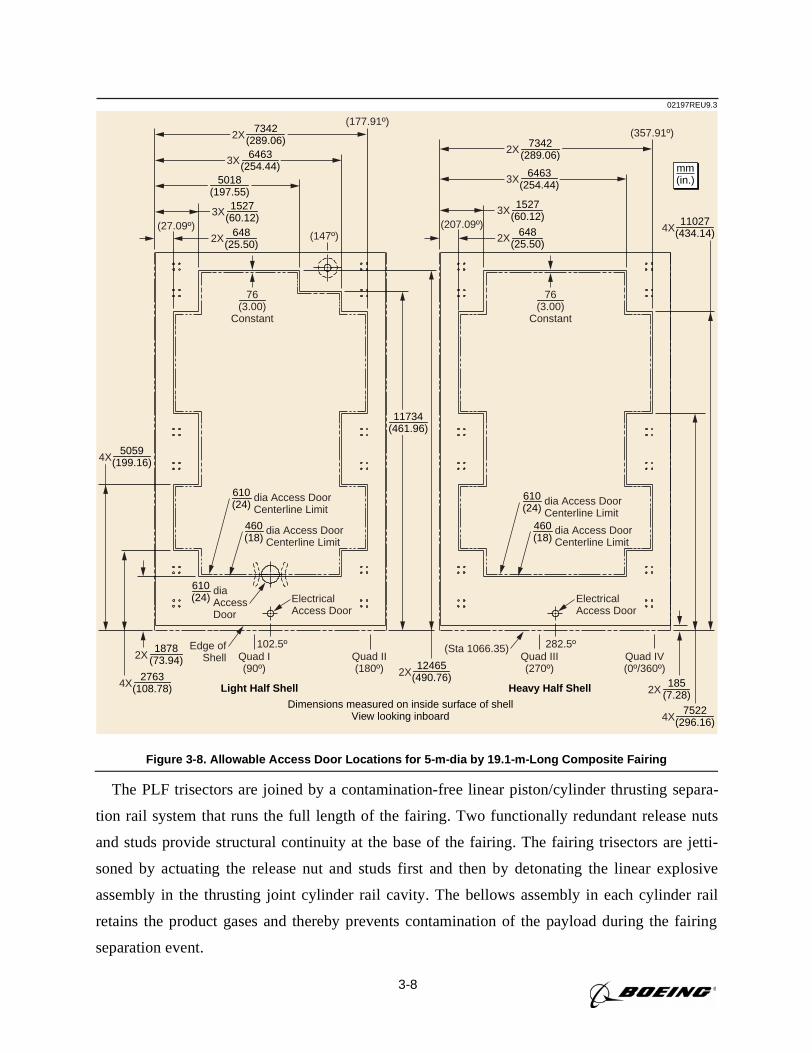
3-8
The PLF trisectors are joined by a contamination-free linear piston/cylinder thrusting separa-
tion rail system that runs the full length of the fairing. Two functionally redundant release nuts
and studs provide structural continuity at the base of the fairing. The fairing trisectors are jetti-
soned by actuating the release nut and studs first and then by detonating the linear explosive
assembly in the thrusting joint cylinder rail cavity. The bellows assembly in each cylinder rail
retains the product gases and thereby prevents contamination of the payload during the fairing
separation event.
Dimensions measured on inside surface of shellView looking inboard
Light Half Shell Heavy Half Shell
02197REU9.3
102.5º 282.5º
(147º)(27.09º)
(177.91º)
(207.09º)
(357.91º)
Quad I(90º)
Quad II(180º)
Quad III(270º)
Quad IV(0º/360º)
Electrical Access Door
Electrical Access Door
Edge ofShell
(Sta 1066.35)
mm(in.)
11734(461.96)
4X 5059
(199.16)
4X 11027
(434.14)
2X 12465
(490.76)
4X 7522
(296.16)
2X 185
(7.28)
76(3.00)
Constant
76(3.00)
Constant
4X 2763
(108.78)
2X 1878
(73.94)
3X 1527(60.12)
2X 648(25.50)
5018(197.55)
7342(289.06)6463
(254.44)3X
3X 1527(60.12)
7342(289.06)
6463(254.44)3X
2X
2X 648(25.50)
2X
dia Access DoorCenterline Limit
dia Access DoorCenterline Limit
610(24)
460(18)
diaAccessDoor
610(24)
dia Access DoorCenterline Limit
dia Access DoorCenterline Limit
610(24)
460(18)
Figure 3-8. Allowable Access Door Locations for 5-m-dia by 19.1-m-Long Composite Fairing
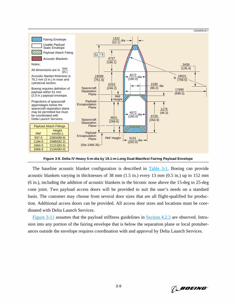
3-9
The baseline acoustic blanket configuration is described inTable 3-1. Boeing can provide
acoustic blankets varying in thicknesses of 38 mm (1.5 in.) every 13 mm (0.5 in.) up to 152 mm
(6 in.), including the addition of acoustic blankets in the biconic nose above the 15-deg to 25-deg
cone joint. Two payload access doors will be provided to suit the user’s needs on a standard
basis. The customer may choose from several door sizes that are all flight-qualified for produc-
tion. Additional access doors can be provided. All access door sizes and locations must be coor-
dinated with Delta Launch Services.
Figure 3-11assumes that the payload stiffness guidelines inSection 4.2.3are observed. Intru-
sion into any portion of the fairing envelope that is below the separation plane or local protuber-
ances outside the envelope requires coordination with and approval by Delta Launch Services.
02028REU9.7
mm(in.)
Usable PayloadStatic Envelope
Fairing Envelope
All dimensions are in
Payload Attach Fitting
Acoustic blanket thickness is76.2 mm (3 in.) in nose andcylindrical section.
Projections of spacecraftappendages below thespacecraft separation planemay be permitted but mustbe coordinated with Delta Launch Services.
Boeing requires definition ofpayload within 51 mm(2.0 in.) payload envelope.
Acoustic Blankets
Notes:
6253(246.2)
6729(264.9)
1176(46.3)
PAFHeight
PAF Height
2190(86.2)
1322(52.1)
dia
PayloadEncapsulation
Plane
SpacecraftSeparation
Plane
PayloadEncapsulation
Plane
SpacecraftSeparation
Plane
5131(202.0)
19098(751.9)
4572(180.0)
dia
dia
R
4572(180.0)
dia
dia
62.7 ft
18021(709.5)
3439(135.4)
4727(186.1)
6821(268.6)
17690(696.5)
(Sta 1066.35)
937-51194-51664-51666-5
2283/(89.9)2088/(82.2)2121/(83.5)2134/(84.0)
PAFHeight
mm/(in.)
Payload Attach Fittings
Figure 3-9. Delta IV Heavy 5-m-dia by 19.1-m-Long Dual-Manifest Fairing Payload Envelope
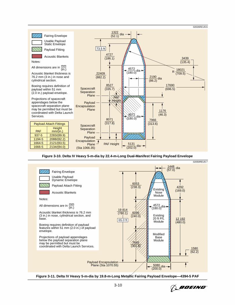
3-10
02026REU9.6
mm(in.)
Usable PayloadStatic Envelope
Fairing Envelope
All dimensions are in
Payload Fitting
Acoustic blanket thickness is76.2 mm (3 in.) in nose andcylindrical section.
Projections of spacecraftappendages below thespacecraft separation planemay be permitted but must becoordinated with Delta LaunchServices.
Boeing requires definition ofpayload within 51 mm(2.0 in.) payload envelope.
Acoustic Blankets
Notes:
8527(335.7)
7966(313.6)
1176(46.3)
PAFHeight
PAF Height
2190(86.2)
1322(52.1)
dia
dia
PayloadEncapsulation
Plane(Sta 1066.35)
SpacecraftSeparation
Plane
PayloadEncapsulation
Plane
SpacecraftSeparation
Plane
5131(202.0)
22409(882.2)
4572(180.0)
dia R
4572(180.0)
dia
dia
73.5 ft
18021(709.5)
3439(135.4)
17690(696.5)
4727(186.1)
8071(317.8)
937-51194-51664-51666-5
2283/(89.9)2088/(82.2)2121/(83.5)2134/(84.0)
PAFHeight
mm/(in.)
Payload Attach Fittings
Figure 3-10. Delta IV Heavy 5-m-dia by 22.4-m-Long Dual-Manifest Fairing Payload Envelope
02050REU9.7
mm(in.)
Usable PayloadDynamic Envelope
Fairing Envelope
All dimensions are in
Payload Attach Fitting
Acoustic blanket thickness is 76.2 mm(3 in.) in nose, cylindrical section, andbase.
Boeing requires definition of payloadfeatures within 51 mm (2.0 in.) of payloadenvelope.
Projections of payload appendagesbelow the payload separation planemay be permitted but must becoordinated with Delta Launch Services.
Acoustic Blankets
Notes:
ModifiedBase
Module
4572(180.0)
ExistingNose
Module
Existing20 ft P/LModule
Payload EncapsulationPlane (Sta 1070.55)
6053(238.3)
6096(240.0)
7665(301.8)
19 814(780.1)
5080(200.0)
1580(62.2)
4292(169.0)
12 192(480.0)
1448(57.0)
dia
dia
dia
65.0 ft
Figure 3-11. Delta IV Heavy 5-m-dia by 19.8-m-Long Metallic Fairing Payload Envelope—4394-5 PAF
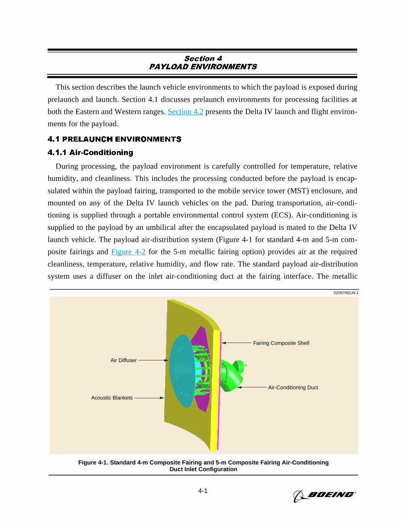
4-1
Section 4
PAYLOAD ENVIRONMENTS
This section describes the launch vehicle environments to which the payload is exposed during
prelaunch and launch. Section 4.1 discusses prelaunch environments for processing facilities at
both the Eastern and Western ranges.Section 4.2presents the Delta IV launch and flight environ-
ments for the payload.
4.1 PRELAUNCH ENVIRONMENTS
4.1.1 Air-Conditioning
During processing, the payload environment is carefully controlled for temperature, relative
humidity, and cleanliness. This includes the processing conducted before the payload is encap-
sulated within the payload fairing, transported to the mobile service tower (MST) enclosure, and
mounted on any of the Delta IV launch vehicles on the pad. During transportation, air-condi-
tioning is supplied through a portable environmental control system (ECS). Air-conditioning is
supplied to the payload by an umbilical after the encapsulated payload is mated to the Delta IV
launch vehicle. The payload air-distribution system (Figure 4-1 for standard 4-m and 5-m com-
posite fairings andFigure 4-2for the 5-m metallic fairing option) provides air at the required
cleanliness, temperature, relative humidity, and flow rate. The standard payload air-distribution
system uses a diffuser on the inlet air-conditioning duct at the fairing interface. The metallic
02097REU9.1
Fairing Composite Shell
Air Diffuser
Acoustic Blankets
Air-Conditioning Duct
Figure 4-1. Standard 4-m Composite Fairing and 5-m Composite Fairing Air-ConditioningDuct Inlet Configuration
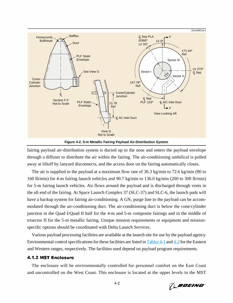
4-2
fairing payload air-distribution system is ducted up to the nose and enters the payload envelope
through a diffuser to distribute the air within the fairing. The air-conditioning umbilical is pulled
away at liftoff by lanyard disconnects, and the access door on the fairing automatically closes.
The air is supplied to the payload at a maximum flow rate of 36.3 kg/min to 72.6 kg/min (80 to
160 lb/min) for 4-m fairing launch vehicles and 90.7 kg/min to 136.0 kg/min (200 to 300 lb/min)
for 5-m fairing launch vehicles. Air flows around the payload and is discharged through vents in
the aft end of the fairing. At Space Launch Complex 37 (SLC-37) and SLC-6, the launch pads will
have a backup system for fairing air-conditioning. A GN2 purge line to the payload can be accom-
modated through the air-conditioning duct. The air-conditioning duct is below the cone/cylinder
junction in the Quad I/Quad II half for the 4-m and 5-m composite fairings and in the middle of
trisector II for the 5-m metallic fairing. Unique mission requirements or equipment and mission-
specific options should be coordinated with Delta Launch Services.
Various payload processing facilities are available at the launch site for use by the payload agency.
Environmental control specifications for these facilities are listed inTables 4-1and4-2for the Eastern
and Western ranges, respectively. The facilities used depend on payload program requirements.
4.1.2 MST Enclosure
The enclosure will be environmentally controlled for personnel comfort on the East Coast
and uncontrolled on the West Coast. This enclosure is located at the upper levels in the MST
02134REU9.4
Baffles
Duct
PLF StaticEnvelope
PLF StaticEnvelope
C AC Inlet Duct
LV 273ºC Sep
147.78ºRef
171.44ºRef
LV 0ºF
F
Sector I
Sector III
Sector II
HoneycombBulkhead
Cone/CylinderJunction
Cone/CylinderJunction
See View G
Section F-FNot to Scale
View GNot to Scale
View Looking Aft
CL
L
L
C A/C Inlet DuctL
C SepPLF 153º
L
C Sep PLA0/360º LV 33º
L
21.78Ref
Figure 4-2. 5-m Metallic Fairing Payload Air-Distribution System
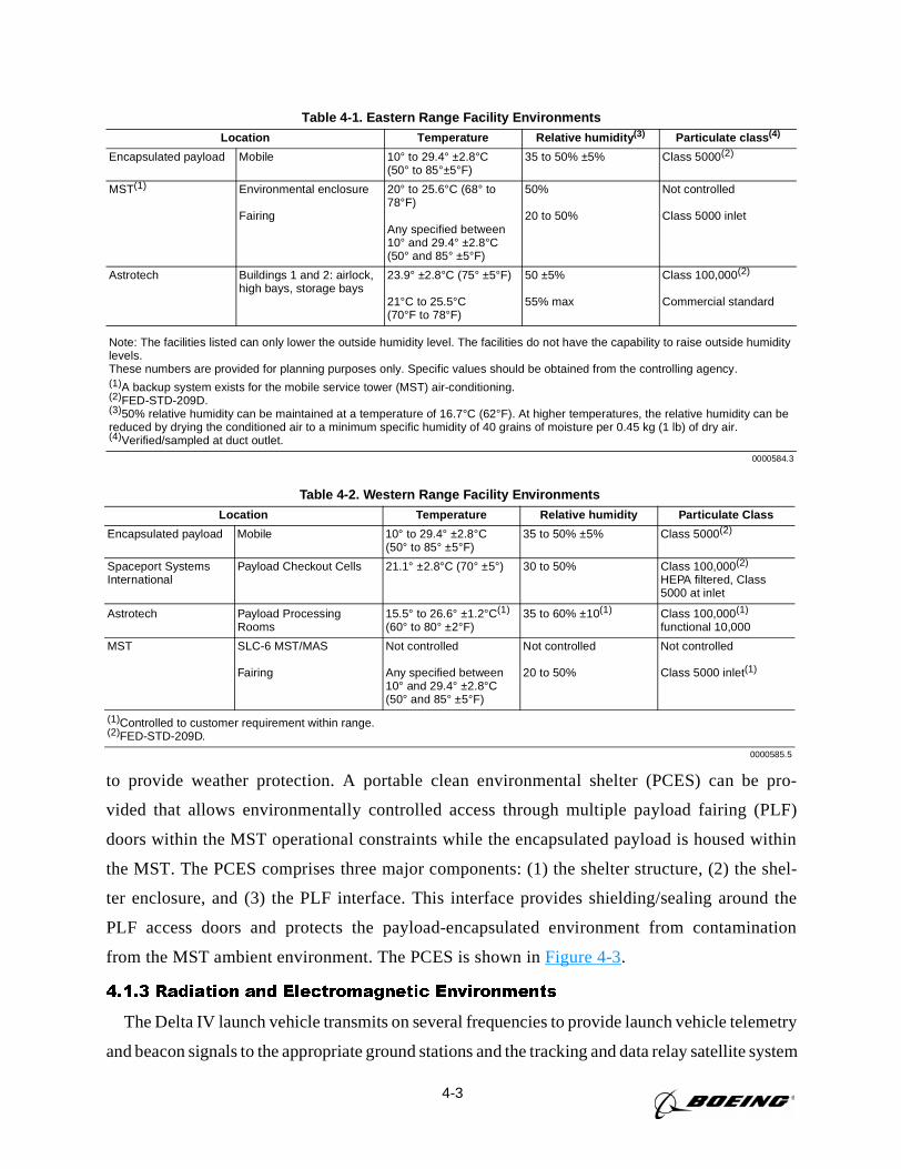
4-3
to provide weather protection. A portable clean environmental shelter (PCES) can be pro-
vided that allows environmentally controlled access through multiple payload fairing (PLF)
doors within the MST operational constraints while the encapsulated payload is housed within
the MST. The PCES comprises three major components: (1) the shelter structure, (2) the shel-
ter enclosure, and (3) the PLF interface. This interface provides shielding/sealing around the
PLF access doors and protects the payload-encapsulated environment from contamination
from the MST ambient environment. The PCES is shown inFigure 4-3.
4.1.3 Radiation and Electromagnetic Environments
The Delta IV launch vehicle transmits on several frequencies to provide launch vehicle telemetry
and beacon signals to the appropriate ground stations and the tracking and data relay satellite system
Table 4-1. Eastern Range Facility EnvironmentsLocation Temperature Relative humidity (3) Particulate class (4)
Encapsulated payload Mobile 10° to 29.4° ±2.8°C(50° to 85°±5°F)
35 to 50% ±5% Class 5000(2)
MST(1) Environmental enclosure
Fairing
20° to 25.6°C (68° to78°F)
Any specified between10° and 29.4° ±2.8°C(50° and 85° ±5°F)
50%
20 to 50%
Not controlled
Class 5000 inlet
Astrotech Buildings 1 and 2: airlock,high bays, storage bays
23.9° ±2.8°C (75° ±5°F)
21°C to 25.5°C(70°F to 78°F)
50 ±5%
55% max
Class 100,000(2)
Commercial standard
Note: The facilities listed can only lower the outside humidity level. The facilities do not have the capability to raise outside humiditylevels.These numbers are provided for planning purposes only. Specific values should be obtained from the controlling agency.(1)A backup system exists for the mobile service tower (MST) air-conditioning.(2)FED-STD-209D.(3)50% relative humidity can be maintained at a temperature of 16.7°C (62°F). At higher temperatures, the relative humidity can bereduced by drying the conditioned air to a minimum specific humidity of 40 grains of moisture per 0.45 kg (1 lb) of dry air.(4)Verified/sampled at duct outlet.
0000584.3
Table 4-2. Western Range Facility EnvironmentsLocation Temperature Relative humidity Particulate Class
Encapsulated payload Mobile 10° to 29.4° ±2.8°C(50° to 85° ±5°F)
35 to 50% ±5% Class 5000(2)
Spaceport SystemsInternational
Payload Checkout Cells 21.1° ±2.8°C (70° ±5°) 30 to 50% Class 100,000(2)
HEPA filtered, Class5000 at inlet
Astrotech Payload ProcessingRooms
15.5° to 26.6° ±1.2°C(1)
(60° to 80° ±2°F)35 to 60% ±10(1) Class 100,000(1)
functional 10,000
MST SLC-6 MST/MAS
Fairing
Not controlled
Any specified between10° and 29.4° ±2.8°C(50° and 85° ±5°F)
Not controlled
20 to 50%
Not controlled
Class 5000 inlet(1)
(1)Controlled to customer requirement within range.(2)FED-STD-209D.
0000585.5
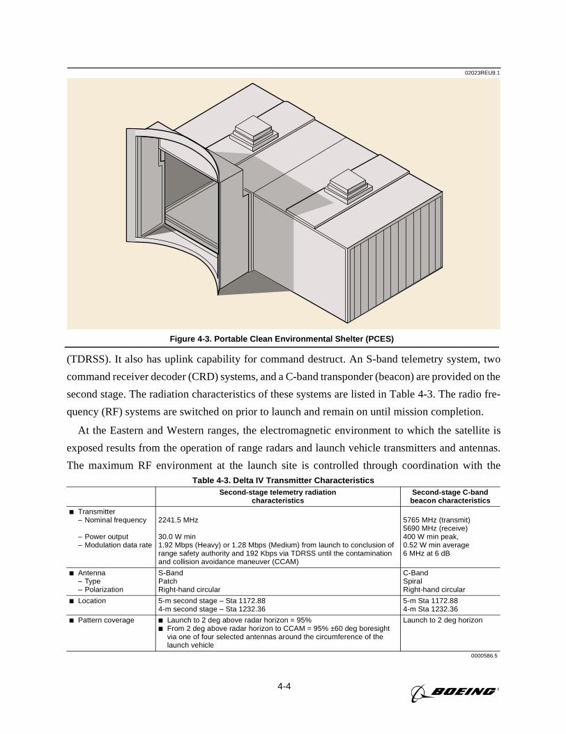
4-4
(TDRSS). It also has uplink capability for command destruct. An S-band telemetry system, two
command receiver decoder (CRD) systems, and a C-band transponder (beacon) are provided on the
second stage. The radiation characteristics of these systems are listed in Table 4-3. The radio fre-
quency (RF) systems are switched on prior to launch and remain on until mission completion.
At the Eastern and Western ranges, the electromagnetic environment to which the satellite is
exposed results from the operation of range radars and launch vehicle transmitters and antennas.
The maximum RF environment at the launch site is controlled through coordination with theTable 4-3. Delta IV Transmitter Characteristics
Second-stage telemetry radiationcharacteristics
Second-stage C-bandbeacon characteristics
Transmitter– Nominal frequency
– Power output– Modulation data rate
2241.5 MHz
30.0 W min1.92 Mbps (Heavy) or 1.28 Mbps (Medium) from launch to conclusion ofrange safety authority and 192 Kbps via TDRSS until the contaminationand collision avoidance maneuver (CCAM)
5765 MHz (transmit)5690 MHz (receive)400 W min peak,0.52 W min average6 MHz at 6 dB
Antenna– Type– Polarization
S-BandPatchRight-hand circular
C-BandSpiralRight-hand circular
Location 5-m second stage – Sta 1172.884-m second stage – Sta 1232.36
5-m Sta 1172.884-m Sta 1232.36
Pattern coverage Launch to 2 deg above radar horizon = 95% From 2 deg above radar horizon to CCAM = 95% ±60 deg boresight
via one of four selected antennas around the circumference of thelaunch vehicle
Launch to 2 deg horizon
0000586.5
02023REU9.1
Figure 4-3. Portable Clean Environmental Shelter (PCES)
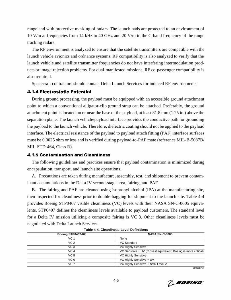
4-5
range and with protective masking of radars. The launch pads are protected to an environment of
10 V/m at frequencies from 14 kHz to 40 GHz and 20 V/m in the C-band frequency of the range
tracking radars.
The RF environment is analyzed to ensure that the satellite transmitters are compatible with the
launch vehicle avionics and ordnance systems. RF compatibility is also analyzed to verify that the
launch vehicle and satellite transmitter frequencies do not have interfering intermodulation prod-
ucts or image-rejection problems. For dual-manifested missions, RF co-passenger compatibility is
also required.
Spacecraft contractors should contact Delta Launch Services for induced RF environments.
4.1.4 Electrostatic Potential
During ground processing, the payload must be equipped with an accessible ground attachment
point to which a conventional alligator-clip ground strap can be attached. Preferably, the ground
attachment point is located on or near the base of the payload, at least 31.8 mm (1.25 in.) above the
separation plane. The launch vehicle/payload interface provides the conductive path for grounding
the payload to the launch vehicle. Therefore, dielectric coating should not be applied to the payload
interface. The electrical resistance of the payload to payload attach fitting (PAF) interface surfaces
must be 0.0025 ohm or less and is verified during payload-to-PAF mate (reference MIL-B-5087B/
MIL-STD-464, Class R).
4.1.5 Contamination and Cleanliness
The following guidelines and practices ensure that payload contamination is minimized during
encapsulation, transport, and launch site operations.
A. Precautions are taken during manufacture, assembly, test, and shipment to prevent contam-
inant accumulations in the Delta IV second-stage area, fairing, and PAF.
B. The fairing and PAF are cleaned using isopropyl alcohol (IPA) at the manufacturing site,
then inspected for cleanliness prior to double-bagging for shipment to the launch site. Table 4-4
provides Boeing STP0407 visible cleanliness (VC) levels with their NASA SN-C-0005 equiva-
lents. STP0407 defines the cleanliness levels available to payload customers. The standard level
for a Delta IV mission utilizing a composite fairing is VC 3. Other cleanliness levels must be
negotiated with Delta Launch Services.Table 4-4. Cleanliness-Level Definitions
Boeing STP0407-0X NASA SN-C-0005VC 1 NoneVC 2 VC StandardVC 3 VC Highly SensitiveVC 4 VC Sensitive + UV (Closest equivalent; Boeing is more critical)VC 5 VC Highly SensitiveVC 6 VC Highly Sensitive + UVVC 7 VC Highly Sensitive + NVR Level A
0000587.2
4-6
Cleanliness Level Definitions
VC 1—All surfaces shall be visibly free of all particulates and nonparticulates visible to the
normal unaided/corrected-vision eye. Particulates are defined as matter of miniature size with
observable length, width, and thickness. Nonparticulates are film matter without definite dimen-
sion. Inspection operations shall be performed under normal shop lighting conditions at a maxi-
mum distance of 0.915 m (3 ft).
VC 2—All surfaces shall be visibly free of all particulates and nonparticulates visible to the
normal unaided/corrected-vision eye. Particulates are defined as matter of miniature size with
observable length, width, and thickness. Nonparticulates are film matter without definite dimen-
sion. Inspection operations shall be performed at incident light levels of 538.2 lux (50 foot-can-
dles [fc]) and observation distances of 1.52 m to 3.05 m (5 ft to 10 ft).
VC 3—All surfaces shall be visibly free of all particulates and nonparticulates visible to the
normal unaided/corrected-vision eye. Particulates are identified as matter of miniature size with
observable length, width, and thickness. Nonparticulates are film matter without definite
dimension. Incident light levels shall be 1076.4 lux to 2152.8 lux (100 fc to 200 fc) at an
observation distance of 45.2 cm (18 in.) or less.
VC 4—All surfaces shall be visibly free of all particulates and nonparticulates visible to the
normal unaided/corrected-vision eye. Particulates are identified as matter of miniature size with
observable length, width, and thickness. Nonparticulates are film matter without definite dimen-
sion. This level requires no particulate count. The source of incident light shall be a 300-W explo-
sion-proof droplight held at distance of 1.52 m (5 ft), maximum, from the local area of inspection.
There shall be no hydrocarbon contamination on surfaces specifying VC 4 cleanliness.
VC 5—All surfaces shall be visibly free of all particulates and nonparticulates visible to the
normal unaided/corrected-vision eye. Particulates are identified as matter of miniature size with
observable length, width, and thickness. Nonparticulates are film matter without definite dimen-
sion. This level requires no particulate count. Incident light levels shall be 1076.4 lux to 2152.8
lux (100 fc to 200 fc) at an observation distance of 15.2 cm to 45.7 cm (6 in. to 18 in.). Cleaning
must be done in a class 100,000 or better clean room.
VC 6—All surfaces shall be visibly free of all particulates and nonparticulates visible to the
normal unaided/corrected-vision eye. Particulates are identified as matter of miniature size with
observable length, width, and thickness. Nonparticulates are film matter without definite dimen-
sion. This level requires no particulate count. Incident light levels shall be 1076.4 lux to 2152.8
lux (100 fc to 200 fc) at an observation distance of 15.2 cm to 45.7 cm (6 in. to 18 in.). Additional
incident light requirements are 8 W minimum of long-wave ultraviolet (UV) light at 15.2 cm to
45.7-cm (6 in. to 18-in.) observation distance in a darkened work area. Protective eyewear may be
used as required with UV lamps. Cleaning must be done in a class 100,000 or better clean room.
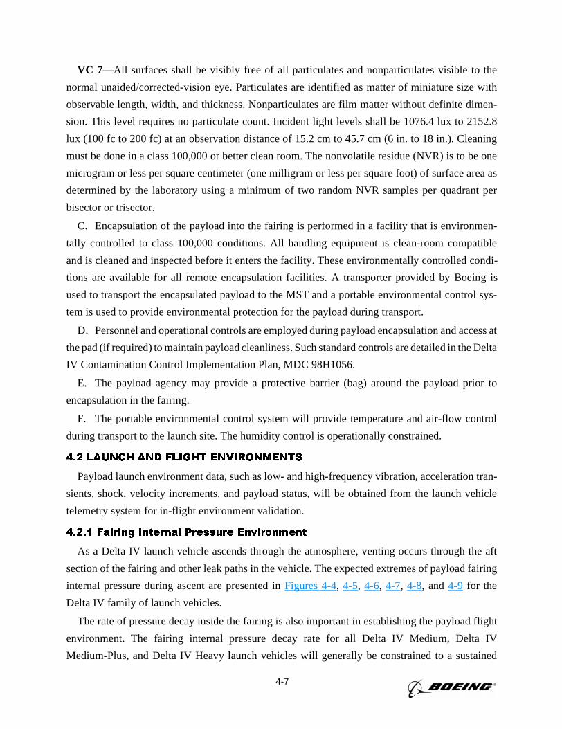
4-7
VC 7—All surfaces shall be visibly free of all particulates and nonparticulates visible to the
normal unaided/corrected-vision eye. Particulates are identified as matter of miniature size with
observable length, width, and thickness. Nonparticulates are film matter without definite dimen-
sion. This level requires no particulate count. Incident light levels shall be 1076.4 lux to 2152.8
lux (100 fc to 200 fc) at an observation distance of 15.2 cm to 45.7 cm (6 in. to 18 in.). Cleaning
must be done in a class 100,000 or better clean room. The nonvolatile residue (NVR) is to be one
microgram or less per square centimeter (one milligram or less per square foot) of surface area as
determined by the laboratory using a minimum of two random NVR samples per quadrant per
bisector or trisector.
C. Encapsulation of the payload into the fairing is performed in a facility that is environmen-
tally controlled to class 100,000 conditions. All handling equipment is clean-room compatible
and is cleaned and inspected before it enters the facility. These environmentally controlled condi-
tions are available for all remote encapsulation facilities. A transporter provided by Boeing is
used to transport the encapsulated payload to the MST and a portable environmental control sys-
tem is used to provide environmental protection for the payload during transport.
D. Personnel and operational controls are employed during payload encapsulation and access at
the pad (if required) to maintain payload cleanliness. Such standard controls are detailed in the Delta
IV Contamination Control Implementation Plan, MDC 98H1056.
E. The payload agency may provide a protective barrier (bag) around the payload prior to
encapsulation in the fairing.
F. The portable environmental control system will provide temperature and air-flow control
during transport to the launch site. The humidity control is operationally constrained.
4.2 LAUNCH AND FLIGHT ENVIRONMENTS
Payload launch environment data, such as low- and high-frequency vibration, acceleration tran-
sients, shock, velocity increments, and payload status, will be obtained from the launch vehicle
telemetry system for in-flight environment validation.
4.2.1 Fairing Internal Pressure Environment
As a Delta IV launch vehicle ascends through the atmosphere, venting occurs through the aft
section of the fairing and other leak paths in the vehicle. The expected extremes of payload fairing
internal pressure during ascent are presented inFigures 4-4, 4-5, 4-6, 4-7, 4-8, and4-9 for the
Delta IV family of launch vehicles.
The rate of pressure decay inside the fairing is also important in establishing the payload flight
environment. The fairing internal pressure decay rate for all Delta IV Medium, Delta IV
Medium-Plus, and Delta IV Heavy launch vehicles will generally be constrained to a sustained
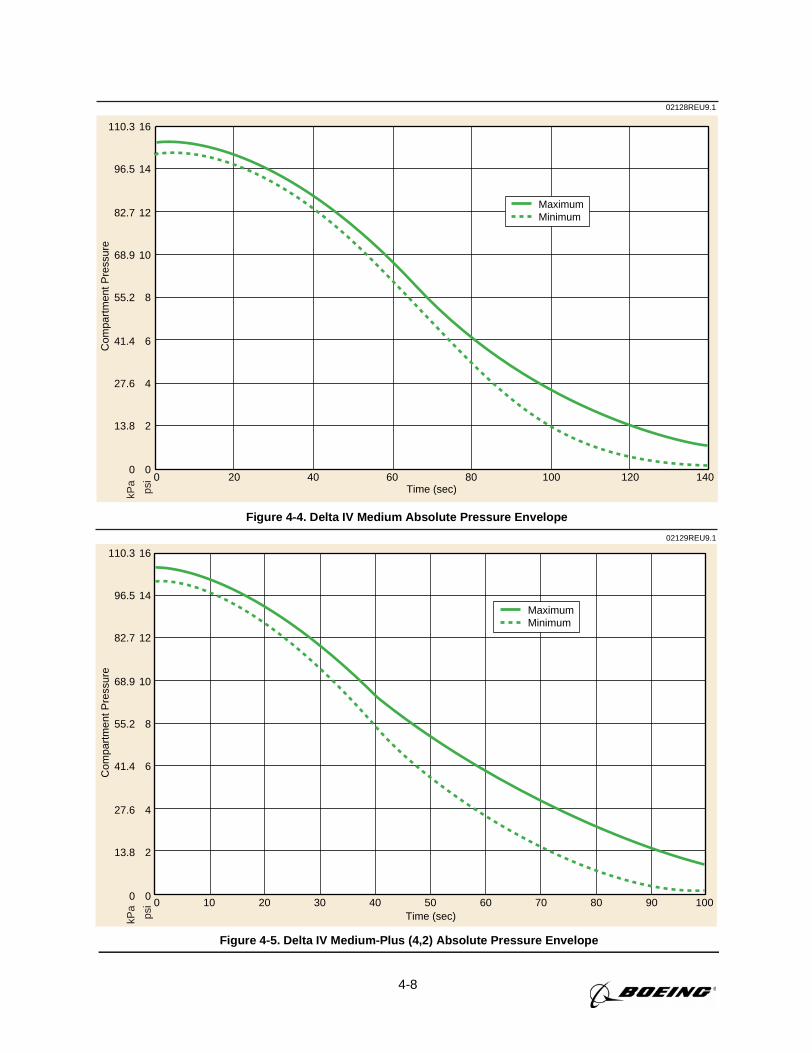
4-8
02128REU9.1
0
2
4
6
8
10
12
14
16
0
13.8
27.6
41.4
55.2
68.9
82.7
96.5
110.3
0 20 40 60 80 100 120 140Time (sec)
Com
part
men
t Pre
ssur
e
MaximumMinimum
kPa
psi
Figure 4-4. Delta IV Medium Absolute Pressure Envelope
0 10 20 30 40 50 60 70 80 90 100Time (sec)
02129REU9.1
0
2
4
6
8
10
12
14
16
0
13.8
27.6
41.4
55.2
68.9
82.7
96.5
110.3
Com
part
men
t Pre
ssur
e
kPa
psi
MaximumMinimum
Figure 4-5. Delta IV Medium-Plus (4,2) Absolute Pressure Envelope
4-9
0 10 20 30 40 50 60 70 80 90 100Time (sec)
MaximumMinimum
02130REU9.1
0
2
4
6
8
10
12
14
16
0
13.8
27.6
41.4
55.2
68.9
82.7
96.5
110.3
Com
part
men
t Pre
ssur
e
kPa
psi
Figure 4-6. Delta IV Medium-Plus (5,2) Absolute Pressure Envelope
0 10 20 30 40 50 60 70 80 90 100Time (sec)
02131REU9.1
MaximumMinimum
0
2
4
6
8
10
12
14
16
0
13.8
27.6
41.4
55.2
68.9
82.7
96.5
110.3
Com
part
men
t Pre
ssur
e
kPa
psi
Figure 4-7. Delta IV Medium-Plus (5,4) Absolute Pressure Envelope
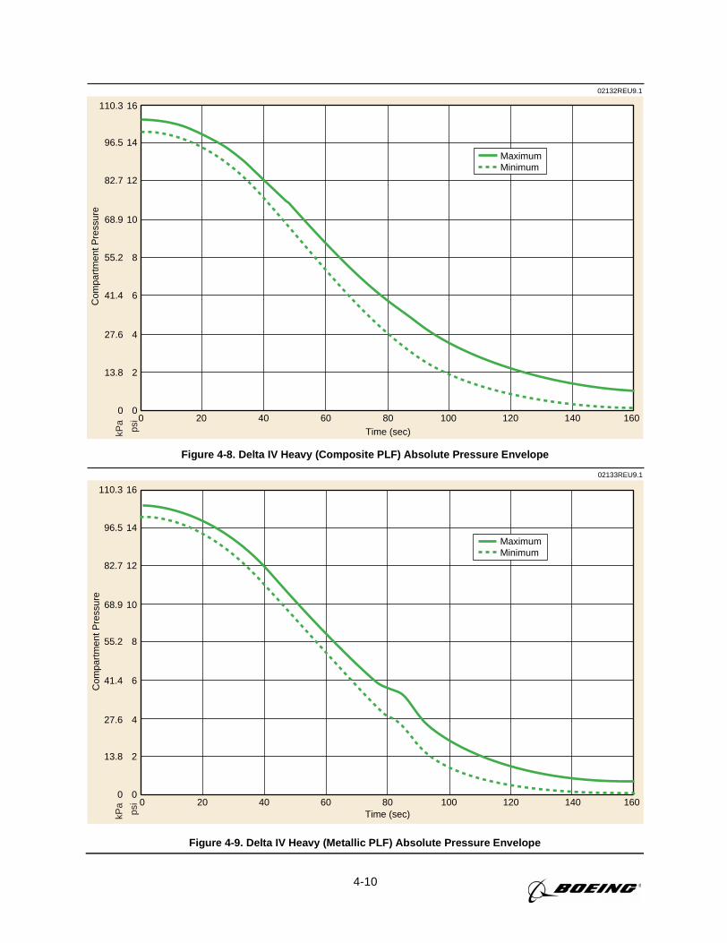
4-10
02132REU9.1
200 40 60 80 100 120 140 160Time (sec)
MaximumMinimum
0
2
4
6
8
10
12
14
16
0
13.8
27.6
41.4
55.2
68.9
82.7
96.5
110.3C
ompa
rtm
ent P
ress
ure
kPa
psi
Figure 4-8. Delta IV Heavy (Composite PLF) Absolute Pressure Envelope
02133REU9.1
0 20 40 60 80 100 120 140 160Time (sec)
MaximumMinimum
0
2
4
6
8
10
12
14
16
0
13.8
27.6
41.4
55.2
68.9
82.7
96.5
110.3
Com
part
men
t Pre
ssur
e
kPa
psi
Figure 4-9. Delta IV Heavy (Metallic PLF) Absolute Pressure Envelope
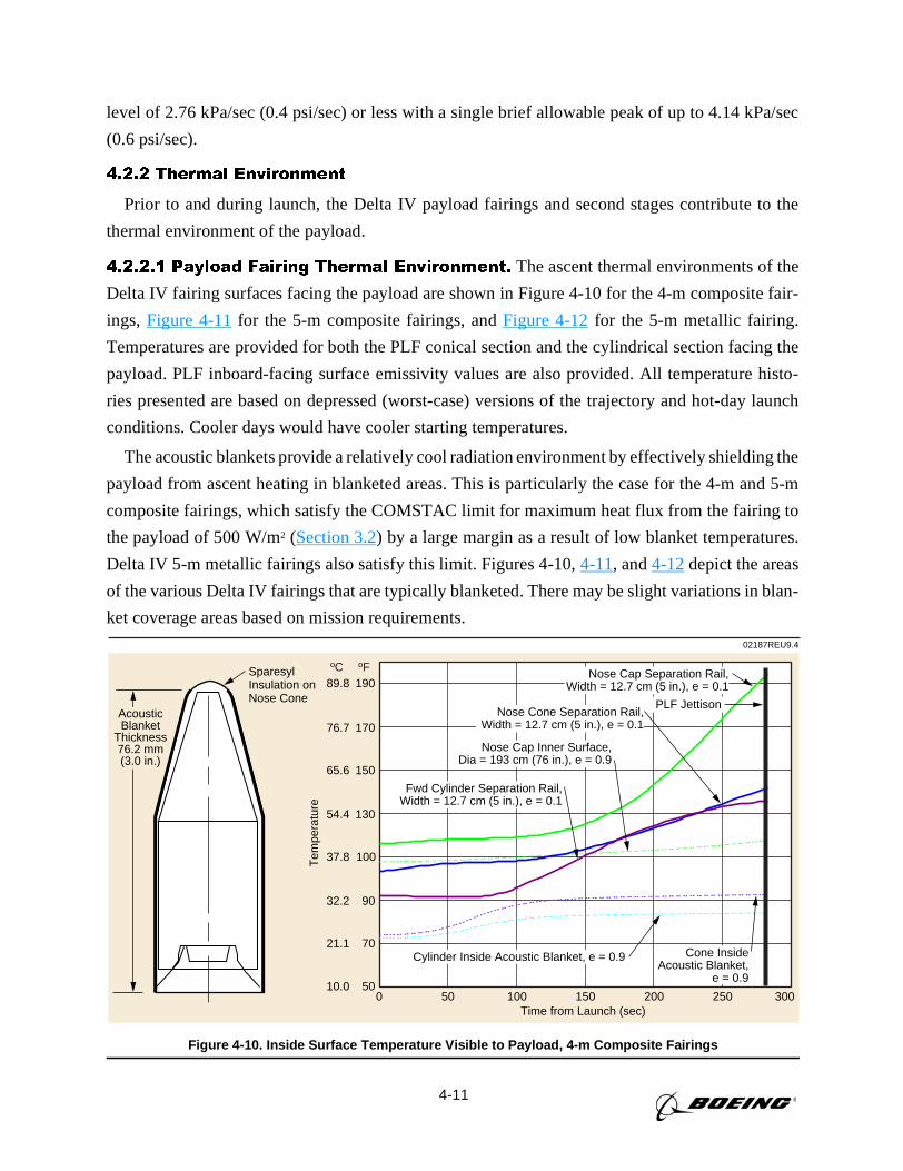
4-11
level of 2.76 kPa/sec (0.4 psi/sec) or less with a single brief allowable peak of up to 4.14 kPa/sec
(0.6 psi/sec).
4.2.2 Thermal Environment
Prior to and during launch, the Delta IV payload fairings and second stages contribute to the
thermal environment of the payload.
4.2.2.1 Payload Fairing Thermal Environment. The ascent thermal environments of the
Delta IV fairing surfaces facing the payload are shown in Figure 4-10 for the 4-m composite fair-
ings, Figure 4-11for the 5-m composite fairings, andFigure 4-12for the 5-m metallic fairing.
Temperatures are provided for both the PLF conical section and the cylindrical section facing the
payload. PLF inboard-facing surface emissivity values are also provided. All temperature histo-
ries presented are based on depressed (worst-case) versions of the trajectory and hot-day launch
conditions. Cooler days would have cooler starting temperatures.
The acoustic blankets provide a relatively cool radiation environment by effectively shielding the
payload from ascent heating in blanketed areas. This is particularly the case for the 4-m and 5-m
composite fairings, which satisfy the COMSTAC limit for maximum heat flux from the fairing to
the payload of 500 W/m2 (Section 3.2) by a large margin as a result of low blanket temperatures.
Delta IV 5-m metallic fairings also satisfy this limit. Figures 4-10,4-11, and4-12depict the areas
of the various Delta IV fairings that are typically blanketed. There may be slight variations in blan-
ket coverage areas based on mission requirements.
AcousticBlanket
Thickness76.2 mm(3.0 in.)
100
90
70
50
130
150
170
190
37.8
32.2
21.1
10.0
54.4
65.6
76.7
89.8
100500 150 200 250 300Time from Launch (sec)
Tem
pera
ture
PLF Jettison
Cylinder Inside Acoustic Blanket, e = 0.9 Cone InsideAcoustic Blanket,
e = 0.9
Nose Cone Separation Rail,Width = 12.7 cm (5 in.), e = 0.1
Fwd Cylinder Separation Rail,Width = 12.7 cm (5 in.), e = 0.1
Nose Cap Inner Surface,Dia = 193 cm (76 in.), e = 0.9
Nose Cap Separation Rail,Width = 12.7 cm (5 in.), e = 0.1
02187REU9.4
SparesylInsulation onNose Cone
ºC ºF
Figure 4-10. Inside Surface Temperature Visible to Payload, 4-m Composite Fairings
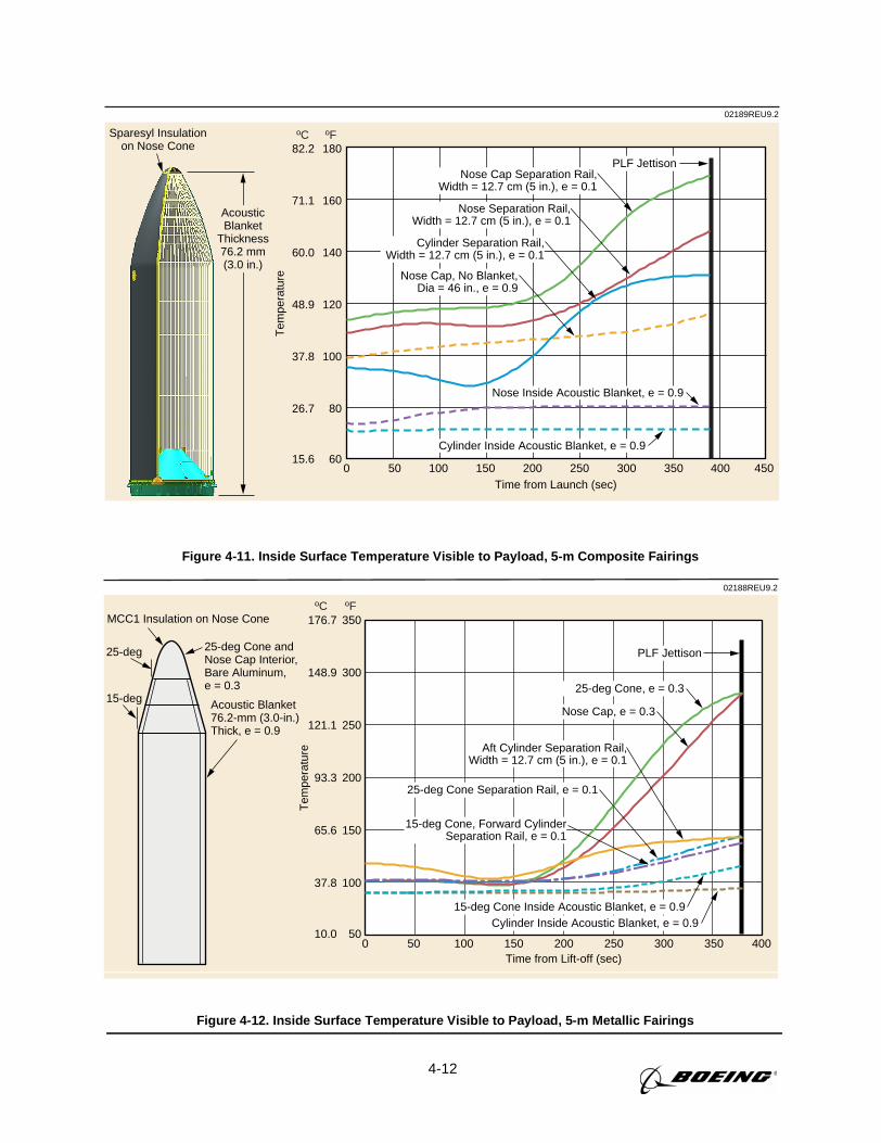
4-12
AcousticBlanket
Thickness76.2 mm(3.0 in.)
100
80
60
120
140
160
180
37.8
26.7
15.6
48.9
60.0
71.1
82.2
100500 150 200 250 300 350 400 450Time from Launch (sec)
Sparesyl Insulationon Nose Cone
Tem
pera
ture
PLF Jettison
02189REU9.2
Cylinder Inside Acoustic Blanket, e = 0.9
Nose Inside Acoustic Blanket, e = 0.9
Nose Separation Rail,Width = 12.7 cm (5 in.), e = 0.1
Cylinder Separation Rail,Width = 12.7 cm (5 in.), e = 0.1
Nose Cap, No Blanket,Dia = 46 in., e = 0.9
Nose Cap Separation Rail,Width = 12.7 cm (5 in.), e = 0.1
ºC ºF
Figure 4-11. Inside Surface Temperature Visible to Payload, 5-m Composite Fairings
25-deg Cone andNose Cap Interior,Bare Aluminum,e = 0.3
25-deg
15-deg
MCC1 Insulation on Nose Cone
Acoustic Blanket76.2-mm (3.0-in.)Thick, e = 0.9
200
150
100
50
250
300
350
93.3
65.6
37.8
10.0
121.1
148.9
176.7
100500 150 200 250 300 350 400Time from Lift-off (sec)
Tem
pera
ture
02188REU9.2
ºC ºF
25-deg Cone, e = 0.3
PLF Jettison
Cylinder Inside Acoustic Blanket, e = 0.915-deg Cone Inside Acoustic Blanket, e = 0.9
25-deg Cone Separation Rail, e = 0.1
15-deg Cone, Forward CylinderSeparation Rail, e = 0.1
Aft Cylinder Separation Rail,Width = 12.7 cm (5 in.), e = 0.1
Nose Cap, e = 0.3
Figure 4-12. Inside Surface Temperature Visible to Payload, 5-m Metallic Fairings
25-deg Cone andNose Cap Interior,Bare Aluminum,e = 0.3
25-deg
15-deg
MCC1 Insulation on Nose Cone
Acoustic Blanket76.2-mm (3.0-in.)Thick, e = 0.9
200
150
100
50
250
300
350
93.3
65.6
37.8
10.0
121.1
148.9
176.7
100500 150 200 250 300 350 400Time from Lift-off (sec)
Tem
pera
ture
02188REU9.2
ºC ºF
25-deg Cone, e = 0.3
PLF Jettison
Cylinder Inside Acoustic Blanket, e = 0.915-deg Cone Inside Acoustic Blanket, e = 0.9
25-deg Cone Separation Rail, e = 0.1
15-deg Cone, Forward CylinderSeparation Rail, e = 0.1
Aft Cylinder Separation Rail,Width = 12.7 cm (5 in.), e = 0.1
Nose Cap, e = 0.3
4-13
Unless otherwise requested, fairing jettison for standard Delta IV missions will occur shortly
after the 3-sigma high theoretical free molecular heating for a flat plate normal to the free stream
drops below 1135 W/m2 (360 Btu/hr ft2) based on the 1962 US Standard Atmosphere. Additional
theoretical free molecular heating rates at fairing jettison (e.g., 1009 W/m2 (320 Btu/hr ft2)) can
be accommodated by the Delta IV family through coordination with Delta Launch Services.
4.2.2.2 On-Orbit Thermal Environment. During coast periods, the Delta IV launch vehi-
cle can be oriented to meet specific sun-angle requirements. A slow roll during a long coast
period can also be used to moderate orbital heating and cooling. The Delta IV roll rate for ther-
mal control is typically 1.5 deg/sec for the 4-m second stage and 1.0 deg/sec for the 5-m second
stage, based on existing Delta launch vehicles.
4.2.2.3 Payload/Launch Vehicle Interface. Boeing will perform a thermodynamic analy-
sis using a customer-provided payload thermal model to define payload temperatures during
ground and flight operations until payload jettison.
4.2.2.4 Stage-Induced Thermal Environments. The plume of the RL10B-2 engine does
not impinge on the payload. Hydrazine thrusters, which are used for attitude control, are located
on the equipment deck, aft of the main propellant tanks. Nozzles are pointed circumferentially
and aft.
4.2.2.5 In-Flight Contamination Environments. Contamination environments from sec-
ond-stage propulsive systems and fairings have been quantified for Delta II and Delta III. Delta IV
4-m and 5-m composite PLFs are comparable to the Delta II and Delta III PLFs, with a unique
acoustic blanket configuration that virtually eliminates contamination of the payload. The blankets
are made of Melamine foam and are attached to the fairing with hook-and-loop fasteners. They are
then covered with carbon-filled kapton face sheets, with all seams sealed with kapton tape. The
PLFs and blankets are cleaned with isopropyl alcohol. During ascent, the blankets vent to the bot-
tom of the PLF, away from the payload. Blanket pressures are kept below 827 Pad (0.12 psid) (with
respect to the fairing internal pressure) to prevent debonding of the blankets. Blanket pressure
models have been verified with flight data. Outgassing from nonmetallics in the fairing is low due
to the low composite fairing temperatures, which are generally below 48.9°C (120°F). Analysis
shows that deposition on the payload envelope from exposed composite material and the carbon-
filled sheets is less than 15Å.
Delta IV second-stage attitude control systems use N2H4 thrusters. The second-stage motor
plumes do not expand enough to impinge on the payload envelope. For payload temperatures
above 93 K (–293°F), only aniline from the N2H4 system plumes will deposit; both species are
quite volatile and evaporate in a reasonable time. A collision contamination avoidance maneuver
(CCAM) is performed after the payload has moved away from the second stage, with a goal of
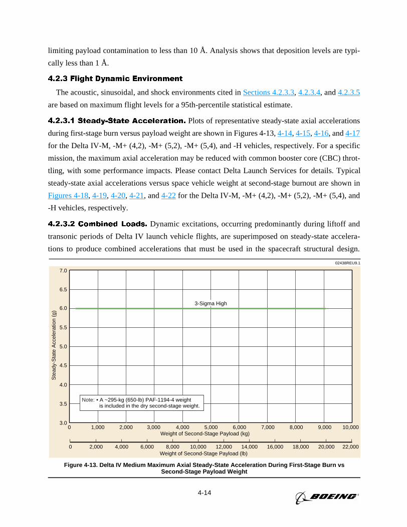
4-14
limiting payload contamination to less than 10 Å. Analysis shows that deposition levels are typi-
cally less than 1 Å.
4.2.3 Flight Dynamic Environment
The acoustic, sinusoidal, and shock environments cited inSections 4.2.3.3, 4.2.3.4, and4.2.3.5
are based on maximum flight levels for a 95th-percentile statistical estimate.
4.2.3.1 Steady-State Acceleration. Plots of representative steady-state axial accelerations
during first-stage burn versus payload weight are shown in Figures 4-13,4-14, 4-15, 4-16, and4-17
for the Delta IV-M, -M+ (4,2), -M+ (5,2), -M+ (5,4), and -H vehicles, respectively. For a specific
mission, the maximum axial acceleration may be reduced with common booster core (CBC) throt-
tling, with some performance impacts. Please contact Delta Launch Services for details. Typical
steady-state axial accelerations versus space vehicle weight at second-stage burnout are shown in
Figures 4-18, 4-19, 4-20, 4-21, and4-22for the Delta IV-M, -M+ (4,2), -M+ (5,2), -M+ (5,4), and
-H vehicles, respectively.
4.2.3.2 Combined Loads. Dynamic excitations, occurring predominantly during liftoff and
transonic periods of Delta IV launch vehicle flights, are superimposed on steady-state accelera-
tions to produce combined accelerations that must be used in the spacecraft structural design.
02438REU9.1
0 2,000 4,000 6,000 8,000 10,000 12,000 14,000 16,000 18,000 20,000 22,000Weight of Second-Stage Payload (lb)
3.0
3.5
4.0
4.5
5.0
5.5
6.0
6.5
7.0
0 1,000 2,000 3,000 4,000 5,000 6,000 7,000 8,000 9,000 10,000Weight of Second-Stage Payload (kg)
Ste
ady-
Sta
te A
ccel
erat
ion
(g)
• A ~295-kg (650-lb) PAF-1194-4 weight is included in the dry second-stage weight.
Note:
3-Sigma High
Figure 4-13. Delta IV Medium Maximum Axial Steady-State Acceleration During First-Stage Burn vsSecond-Stage Payload Weight
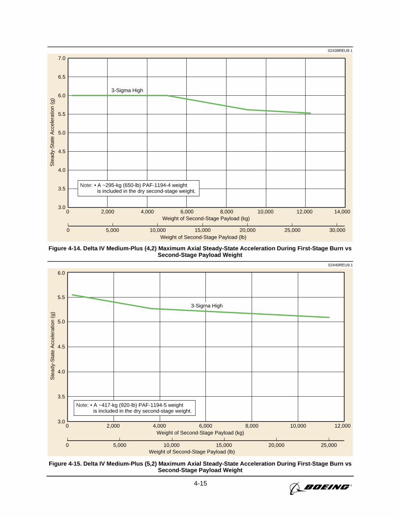
4-15
3.0
3.5
4.0
4.5
5.0
5.5
6.0
6.5
7.0
0 2,000 4,000 6,000 8,000 10,000 12,000 14,000Weight of Second-Stage Payload (kg)
02439REU9.1
3-Sigma High
0 5,000 10,000 15,000 20,000 25,000 30,000Weight of Second-Stage Payload (lb)
Ste
ady-
Sta
te A
ccel
erat
ion
(g)
• A ~295-kg (650-lb) PAF-1194-4 weight is included in the dry second-stage weight.
Note:
Figure 4-14. Delta IV Medium-Plus (4,2) Maximum Axial Steady-State Acceleration During First-Stage Burn vsSecond-Stage Payload Weight
02440REU9.1
Ste
ady-
Sta
te A
ccel
erat
ion
(g)
0 5,000 10,000 15,000 20,000 25,000Weight of Second-Stage Payload (lb)
3.0
3.5
4.0
4.5
5.0
5.5
6.0
0 2,000 4,000 6,000 8,000 10,000 12,000Weight of Second-Stage Payload (kg)
3-Sigma High
• A ~417-kg (920-lb) PAF-1194-5 weight is included in the dry second-stage weight.
Note:
Figure 4-15. Delta IV Medium-Plus (5,2) Maximum Axial Steady-State Acceleration During First-Stage Burn vsSecond-Stage Payload Weight
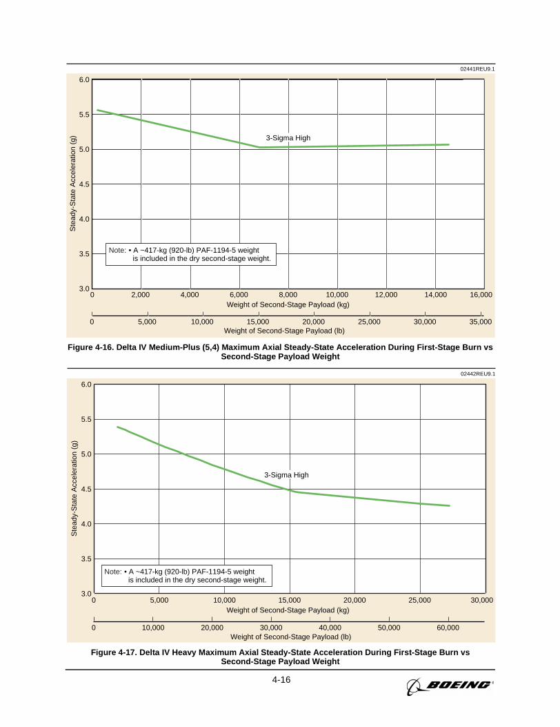
4-16
0 5,000 10,000 15,000 20,000 25,000 30,000 35,000Weight of Second-Stage Payload (lb)
3.0
3.5
4.0
4.5
5.0
5.5
6.0
0 2,000 4,000 6,000 8,000 10,000 12,000 14,000 16,000Weight of Second-Stage Payload (kg)
02441REU9.1S
tead
y-S
tate
Acc
eler
atio
n (g
) 3-Sigma High
• A ~417-kg (920-lb) PAF-1194-5 weight is included in the dry second-stage weight.
Note:
Figure 4-16. Delta IV Medium-Plus (5,4) Maximum Axial Steady-State Acceleration During First-Stage Burn vsSecond-Stage Payload Weight
02442REU9.1
Ste
ady-
Sta
te A
ccel
erat
ion
(g)
0 10,000 20,000 30,000 40,000 50,000 60,000Weight of Second-Stage Payload (lb)
3.0
3.5
4.0
4.5
5.0
5.5
6.0
0 5,000 10,000 15,000 20,000 25,000 30,000Weight of Second-Stage Payload (kg)
3-Sigma High
• A ~417-kg (920-lb) PAF-1194-5 weight is included in the dry second-stage weight.
Note:
Figure 4-17. Delta IV Heavy Maximum Axial Steady-State Acceleration During First-Stage Burn vsSecond-Stage Payload Weight
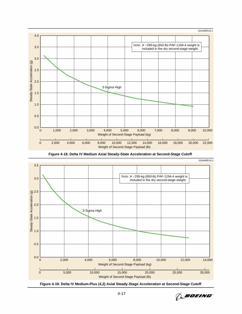
4-17
02443REU9.1S
tead
y-S
tate
Acc
eler
atio
n (g
)
0 2,000 4,000 6,000 8,000 10,000 12,000 14,000 16,000 18,000 20,000 22,000Weight of Second-Stage Payload (lb)
0.0
0.5
1.0
1.5
2.0
2.5
3.0
3.5
4.0
0 1,000 2,000 3,000 4,000 5,000 6,000 7,000 8,000 9,000 10,000Weight of Second-Stage Payload (kg)
A ~295-kg (650-lb) PAF-1194-4 weight isincluded in the dry second-stage weight.
Note:
3-Sigma High
Figure 4-18. Delta IV Medium Axial Steady-State Acceleration at Second-Stage Cutoff
0 5,000 10,000 15,000 20,000 25,000 30,000Weight of Second-Stage Payload (lb)
0.0
0.5
1.0
1.5
2.0
2.5
3.0
3.5
0 2,000 4,000 6,000 8,000 10,000 12,000 14,000Weight of Second-Stage Payload (kg)
02444REU9.1
Ste
ady-
Sta
te A
ccel
erat
ion
(g)
A ~295-kg (650-lb) PAF-1194-4 weight isincluded in the dry second-stage weight.
Note:
3-Sigma High
Figure 4-19. Delta IV Medium-Plus (4,2) Axial Steady-Stage Acceleration at Second-Stage Cutoff
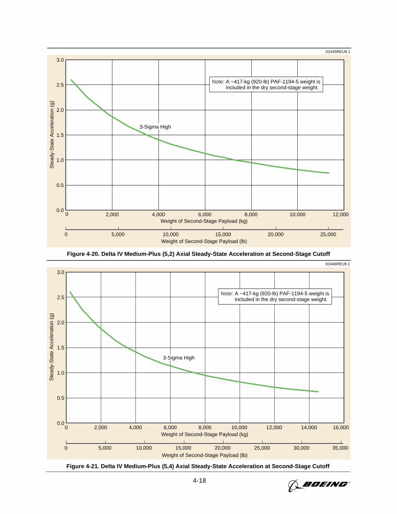
4-18
02445REU9.1S
tead
y-S
tate
Acc
eler
atio
n (g
)
0 5,000 10,000 15,000 20,000 25,000Weight of Second-Stage Payload (lb)
0.0
0.5
1.0
1.5
2.0
2.5
3.0
0 2,000 4,000 6,000 8,000 10,000 12,000Weight of Second-Stage Payload (kg)
3-Sigma High
A ~417-kg (920-lb) PAF-1194-5 weight isincluded in the dry second-stage weight.
Note:
Figure 4-20. Delta IV Medium-Plus (5,2) Axial Steady-State Acceleration at Second-Stage Cutoff
02446REU9.1
Ste
ady-
Sta
te A
ccel
erat
ion
(g)
0 5,000 10,000 15,000 20,000 25,000 30,000 35,000Weight of Second-Stage Payload (lb)
0.0
0.5
1.0
1.5
2.0
2.5
3.0
0 2,000 4,000 6,000 8,000 10,000 12,000 14,000 16,000Weight of Second-Stage Payload (kg)
3-Sigma High
A ~417-kg (920-lb) PAF-1194-5 weight isincluded in the dry second-stage weight.
Note:
Figure 4-21. Delta IV Medium-Plus (5,4) Axial Steady-State Acceleration at Second-Stage Cutoff
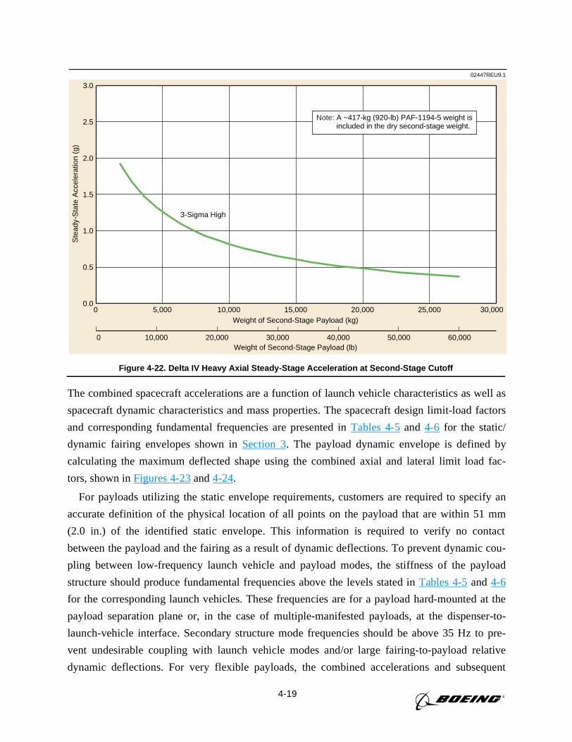
4-19
02447REU9.1S
tead
y-S
tate
Acc
eler
atio
n (g
)
0 10,000 20,000 30,000 40,000 50,000 60,000Weight of Second-Stage Payload (lb)
0.0
0.5
1.0
1.5
2.0
2.5
3.0
0 5,000 10,000 15,000 20,000 25,000 30,000Weight of Second-Stage Payload (kg)
3-Sigma High
A ~417-kg (920-lb) PAF-1194-5 weight isincluded in the dry second-stage weight.
Note:
Figure 4-22. Delta IV Heavy Axial Steady-Stage Acceleration at Second-Stage Cutoff
The combined spacecraft accelerations are a function of launch vehicle characteristics as well as
spacecraft dynamic characteristics and mass properties. The spacecraft design limit-load factors
and corresponding fundamental frequencies are presented inTables 4-5and 4-6 for the static/
dynamic fairing envelopes shown inSection 3. The payload dynamic envelope is defined by
calculating the maximum deflected shape using the combined axial and lateral limit load fac-
tors, shown inFigures 4-23and4-24.
For payloads utilizing the static envelope requirements, customers are required to specify an
accurate definition of the physical location of all points on the payload that are within 51 mm
(2.0 in.) of the identified static envelope. This information is required to verify no contact
between the payload and the fairing as a result of dynamic deflections. To prevent dynamic cou-
pling between low-frequency launch vehicle and payload modes, the stiffness of the payload
structure should produce fundamental frequencies above the levels stated inTables 4-5and4-6
for the corresponding launch vehicles. These frequencies are for a payload hard-mounted at the
payload separation plane or, in the case of multiple-manifested payloads, at the dispenser-to-
launch-vehicle interface. Secondary structure mode frequencies should be above 35 Hz to pre-
vent undesirable coupling with launch vehicle modes and/or large fairing-to-payload relative
dynamic deflections. For very flexible payloads, the combined accelerations and subsequent
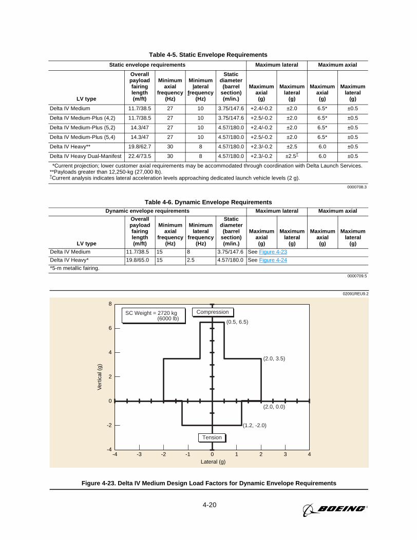
4-20
02091REU9.2
8
6
4
2
0
-2
-4-3
Ver
tical
(g)
-4 -1-2 10Lateral (g)
3 42
Compression
Tension
(1.2, -2.0)
(2.0, 3.5)
(2.0, 0.0)
(0.5, 6.5)
SC Weight = 2720 kg (6000 lb)
Figure 4-23. Delta IV Medium Design Load Factors for Dynamic Envelope Requirements
Table 4-5. Static Envelope Requirements
Static envelope requirements Maximum lateral Maximum axial
LV type
Overallpayloadfairinglength(m/ft)
Minimumaxial
frequency(Hz)
Minimumlateral
frequency(Hz)
Staticdiameter
(barrelsection)(m/in.)
Maximumaxial(g)
Maximumlateral
(g)
Maximumaxial(g)
Maximumlateral
(g)
Delta IV Medium 11.7/38.5 27 10 3.75/147.6 +2.4/-0.2 ±2.0 6.5* ±0.5
Delta IV Medium-Plus (4,2) 11.7/38.5 27 10 3.75/147.6 +2.5/-0.2 ±2.0 6.5* ±0.5
Delta IV Medium-Plus (5,2) 14.3/47 27 10 4.57/180.0 +2.4/-0.2 ±2.0 6.5* ±0.5
Delta IV Medium-Plus (5,4) 14.3/47 27 10 4.57/180.0 +2.5/-0.2 ±2.0 6.5* ±0.5
Delta IV Heavy** 19.8/62.7 30 8 4.57/180.0 +2.3/-0.2 ±2.5 6.0 ±0.5
Delta IV Heavy Dual-Manifest 22.4/73.5 30 8 4.57/180.0 +2.3/-0.2 ±2.5† 6.0 ±0.5
*Current projection; lower customer axial requirements may be accommodated through coordination with Delta Launch Services.**Payloads greater than 12,250-kg (27,000 lb).†Current analysis indicates lateral acceleration levels approaching dedicated launch vehicle levels (2 g).
0000708.3
Table 4-6. Dynamic Envelope RequirementsDynamic envelope requirements Maximum lateral Maximum axial
LV type
Overallpayloadfairinglength(m/ft)
Minimumaxial
frequency(Hz)
Minimumlateral
frequency(Hz)
Staticdiameter
(barrelsection)(m/in.)
Maximumaxial(g)
Maximumlateral
(g)
Maximumaxial(g)
Maximumlateral
(g)
Delta IV Medium 11.7/38.5 15 8 3.75/147.6 See Figure 4-23
Delta IV Heavy* 19.8/65.0 15 2.5 4.57/180.0 See Figure 4-24
*5-m metallic fairing.0000709.5
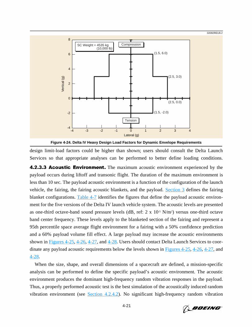
4-21
design limit-load factors could be higher than shown; users should consult the Delta Launch
Services so that appropriate analyses can be performed to better define loading conditions.
4.2.3.3 Acoustic Environment. The maximum acoustic environment experienced by the
payload occurs during liftoff and transonic flight. The duration of the maximum environment is
less than 10 sec. The payload acoustic environment is a function of the configuration of the launch
vehicle, the fairing, the fairing acoustic blankets, and the payload.Section 3defines the fairing
blanket configurations.Table 4-7identifies the figures that define the payload acoustic environ-
ment for the five versions of the Delta IV launch vehicle system. The acoustic levels are presented
as one-third octave-band sound pressure levels (dB, ref: 2 x 10⁻⁵ N/m2) versus one-third octave
band center frequency. These levels apply to the blanketed section of the fairing and represent a
95th percentile space average flight environment for a fairing with a 50% confidence prediction
and a 60% payload volume fill effect. A large payload may increase the acoustic environments
shown inFigures 4-25, 4-26, 4-27, and4-28. Users should contact Delta Launch Services to coor-
dinate any payload acoustic requirements below the levels shown inFigures 4-25, 4-26, 4-27, and
4-28.
When the size, shape, and overall dimensions of a spacecraft are defined, a mission-specific
analysis can be performed to define the specific payload’s acoustic environment. The acoustic
environment produces the dominant high-frequency random vibration responses in the payload.
Thus, a properly performed acoustic test is the best simulation of the acoustically induced random
vibration environment (seeSection 4.2.4.2). No significant high-frequency random vibration
02092REU9.2
8
6
4
2
0
-2
-4-3
Ver
tical
(g)
-4 -1-2 10Lateral (g)
3 42
Compression
Tension
(1.5, -2.0)
(2.5, 3.0)
(2.5, 0.0)
(1.5, 6.0)
SC Weight = 4535 kg (10,000 lb)
Figure 4-24. Delta IV Heavy Design Load Factors for Dynamic Envelope Requirements
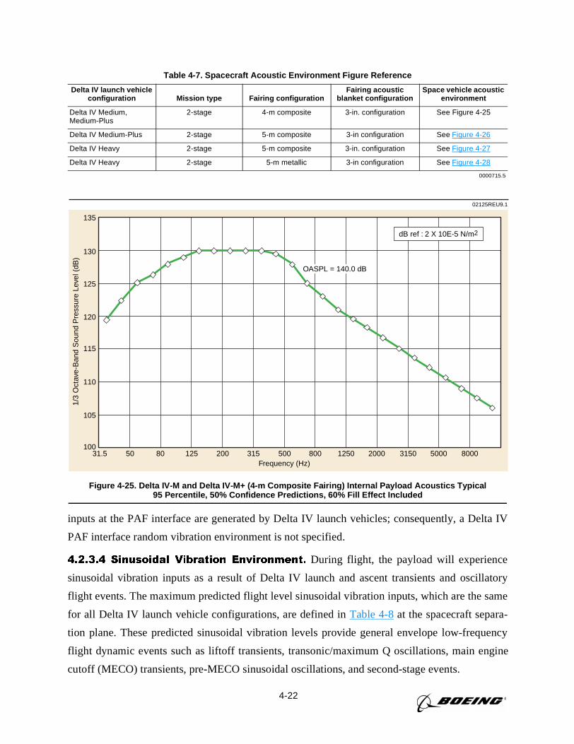
4-22
inputs at the PAF interface are generated by Delta IV launch vehicles; consequently, a Delta IV
PAF interface random vibration environment is not specified.
4.2.3.4 Sinusoidal Vibration Environment. During flight, the payload will experience
sinusoidal vibration inputs as a result of Delta IV launch and ascent transients and oscillatory
flight events. The maximum predicted flight level sinusoidal vibration inputs, which are the same
for all Delta IV launch vehicle configurations, are defined inTable 4-8at the spacecraft separa-
tion plane. These predicted sinusoidal vibration levels provide general envelope low-frequency
flight dynamic events such as liftoff transients, transonic/maximum Q oscillations, main engine
cutoff (MECO) transients, pre-MECO sinusoidal oscillations, and second-stage events.
Table 4-7. Spacecraft Acoustic Environment Figure Reference
Delta IV launch vehicleconfiguration Mission type Fairing configuration
Fairing acousticblanket configuration
Space vehicle acousticenvironment
Delta IV Medium,Medium-Plus
2-stage 4-m composite 3-in. configuration See Figure 4-25
Delta IV Medium-Plus 2-stage 5-m composite 3-in configuration See Figure 4-26
Delta IV Heavy 2-stage 5-m composite 3-in. configuration See Figure 4-27
Delta IV Heavy 2-stage 5-m metallic 3-in configuration See Figure 4-28
0000715.5
Figure 4-25. Delta IV-M and Delta IV-M+ (4-m Composite Fairing) Internal Payload Acoustics Typical95 Percentile, 50% Confidence Predictions, 60% Fill Effect Included
135
130
125
120
115
110
105
10031.5 50 12580 315
Frequency (Hz)
1/3
Oct
ave-
Ban
d S
ound
Pre
ssur
e Le
vel (
dB)
200 20001250800500 800050003150
dB ref : 2 X 10E-5 N/m2
OASPL = 140.0 dB
02125REU9.1
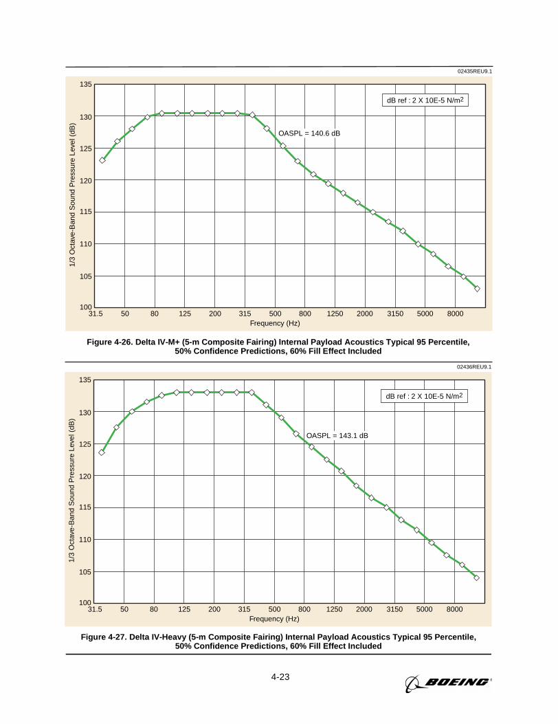
4-23
135
130
125
120
115
110
105
10031.5 50 12580 315
Frequency (Hz)
1/3
Oct
ave-
Ban
d S
ound
Pre
ssur
e Le
vel (
dB)
200 20001250800500 800050003150
OASPL = 140.6 dB
02435REU9.1
dB ref : 2 X 10E-5 N/m2
Figure 4-26. Delta IV-M+ (5-m Composite Fairing) Internal Payload Acoustics Typical 95 Percentile,50% Confidence Predictions, 60% Fill Effect Included
135
130
125
120
115
110
105
10031.5 50 12580 315
Frequency (Hz)
1/3
Oct
ave-
Ban
d S
ound
Pre
ssur
e Le
vel (
dB)
200 20001250800500 800050003150
OASPL = 143.1 dB
02436REU9.1
dB ref : 2 X 10E-5 N/m2
Figure 4-27. Delta IV-Heavy (5-m Composite Fairing) Internal Payload Acoustics Typical 95 Percentile,50% Confidence Predictions, 60% Fill Effect Included
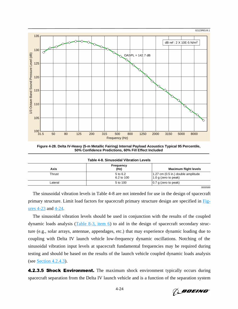
4-24
The sinusoidal vibration levels in Table 4-8 are not intended for use in the design of spacecraft
primary structure. Limit load factors for spacecraft primary structure design are specified inFig-
ures 4-23and4-24.
The sinusoidal vibration levels should be used in conjunction with the results of the coupled
dynamic loads analysis (Table 8-3, item 6) to aid in the design of spacecraft secondary struc-
ture (e.g., solar arrays, antennae, appendages, etc.) that may experience dynamic loading due to
coupling with Delta IV launch vehicle low-frequency dynamic oscillations. Notching of the
sinusoidal vibration input levels at spacecraft fundamental frequencies may be required during
testing and should be based on the results of the launch vehicle coupled dynamic loads analysis
(seeSection 4.2.4.3).
4.2.3.5 Shock Environment. The maximum shock environment typically occurs during
spacecraft separation from the Delta IV launch vehicle and is a function of the separation system
Table 4-8. Sinusoidal Vibration Levels
AxisFrequency
(Hz) Maximum flight levels
Thrust 5 to 6.26.2 to 100
1.27 cm (0.5 in.) double amplitude1.0 g (zero to peak)
Lateral 5 to 100 0.7 g (zero to peak)
0000589
02123REU9.1
135
130
125
120
115
110
105
10031.5 50 12580 315
Frequency (Hz)
1/3
Oct
ave-
Ban
d S
ound
Pre
ssur
e Le
vel (
dB)
200 20001250800500 800050003150
OASPL = 142.7 dB
dB ref : 2 X 10E-5 N/m2
Figure 4-28. Delta IV-Heavy (5-m Metallic Fairing) Internal Payload Acoustics Typical 95 Percentile,50% Confidence Predictions, 60% Fill Effect Included
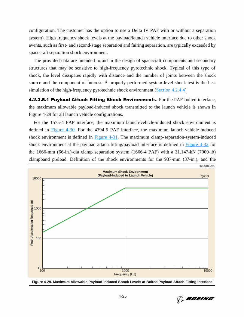
4-25
configuration. The customer has the option to use a Delta IV PAF with or without a separation
system). High frequency shock levels at the payload/launch vehicle interface due to other shock
events, such as first- and second-stage separation and fairing separation, are typically exceeded by
spacecraft separation shock environment.
The provided data are intended to aid in the design of spacecraft components and secondary
structures that may be sensitive to high-frequency pyrotechnic shock. Typical of this type of
shock, the level dissipates rapidly with distance and the number of joints between the shock
source and the component of interest. A properly performed system-level shock test is the best
simulation of the high-frequency pyrotechnic shock environment (Section 4.2.4.4)
4.2.3.5.1 Payload Attach Fitting Shock Environments. For the PAF-bolted interface,
the maximum allowable payload-induced shock transmitted to the launch vehicle is shown in
Figure 4-29 for all launch vehicle configurations.
For the 1575-4 PAF interface, the maximum launch-vehicle-induced shock environment is
defined in Figure 4-30. For the 4394-5 PAF interface, the maximum launch-vehicle-induced
shock environment is defined inFigure 4-31. The maximum clamp-separation-system-induced
shock environment at the payload attach fitting/payload interface is defined inFigure 4-32for
the 1666-mm (66-in.)-dia clamp separation system (1666-4 PAF) with a 31.147-kN (7000-lb)
clampband preload. Definition of the shock environments for the 937-mm (37-in.), and the02120REU9.1
Maximum Shock Environment(Payload-Induced to Launch Vehicle)
10000
1000
100
10100
Frequency (Hz)
Pea
k A
ccel
erat
ion
Res
pons
e (g
)
1000 10000
Q=10
Figure 4-29. Maximum Allowable Payload-Induced Shock Levels at Bolted Payload Attach Fitting Interface
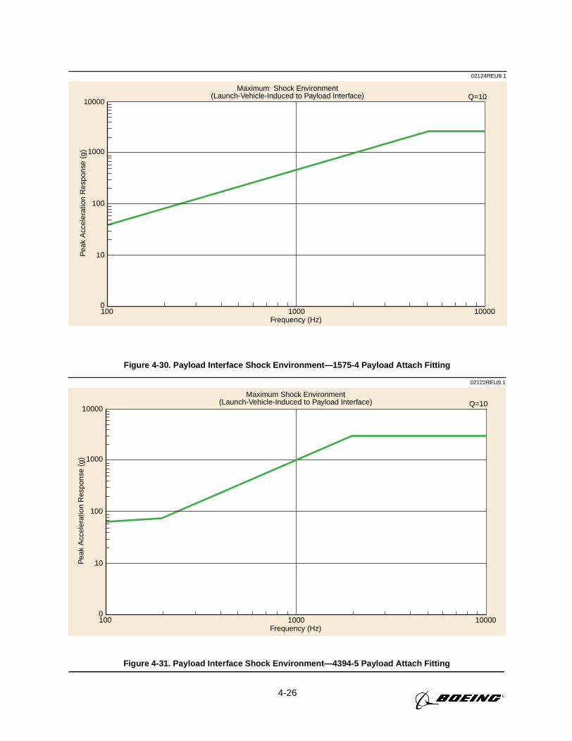
4-26
02124REU9.1
10000
1000
100
10
0100
Frequency (Hz)
Maximum Shock Environment(Launch-Vehicle-Induced to Payload Interface)
Pea
k A
ccel
erat
ion
Res
pons
e (g
)
1000 10000
Q=10
Figure 4-30. Payload Interface Shock Environment—1575-4 Payload Attach Fitting
02122REU9.1
10000
1000
100
10
0100
Frequency (Hz)
Maximum Shock Environment(Launch-Vehicle-Induced to Payload Interface)
Pea
k A
ccel
erat
ion
Res
pons
e (g
)
1000 10000
Q=10
Figure 4-31. Payload Interface Shock Environment—4394-5 Payload Attach Fitting
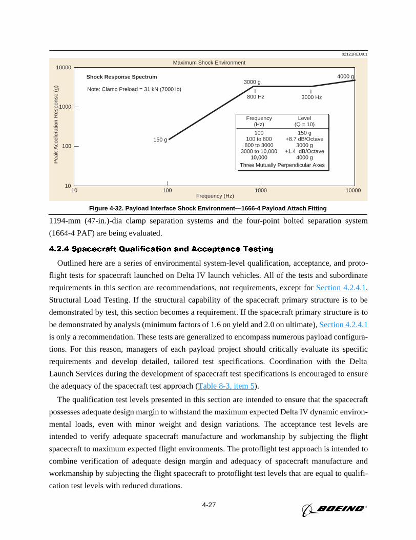
4-27
1194-mm (47-in.)-dia clamp separation systems and the four-point bolted separation system
(1664-4 PAF) are being evaluated.
4.2.4 Spacecraft Qualification and Acceptance Testing
Outlined here are a series of environmental system-level qualification, acceptance, and proto-
flight tests for spacecraft launched on Delta IV launch vehicles. All of the tests and subordinate
requirements in this section are recommendations, not requirements, except forSection 4.2.4.1,
Structural Load Testing. If the structural capability of the spacecraft primary structure is to be
demonstrated by test, this section becomes a requirement. If the spacecraft primary structure is to
be demonstrated by analysis (minimum factors of 1.6 on yield and 2.0 on ultimate),Section 4.2.4.1
is only a recommendation. These tests are generalized to encompass numerous payload configura-
tions. For this reason, managers of each payload project should critically evaluate its specific
requirements and develop detailed, tailored test specifications. Coordination with the Delta
Launch Services during the development of spacecraft test specifications is encouraged to ensure
the adequacy of the spacecraft test approach (Table 8-3, item 5).
The qualification test levels presented in this section are intended to ensure that the spacecraft
possesses adequate design margin to withstand the maximum expected Delta IV dynamic environ-
mental loads, even with minor weight and design variations. The acceptance test levels are
intended to verify adequate spacecraft manufacture and workmanship by subjecting the flight
spacecraft to maximum expected flight environments. The protoflight test approach is intended to
combine verification of adequate design margin and adequacy of spacecraft manufacture and
workmanship by subjecting the flight spacecraft to protoflight test levels that are equal to qualifi-
cation test levels with reduced durations.
02121REU9.1
10
100
1000
10000
10 100 1000 10000Frequency (Hz)
Pea
k A
ccel
erat
ion
Res
pons
e (g
)
3000 g4000 g
Frequency(Hz)
Level(Q = 10)
Three Mutually Perpendicular Axes
150 g
I800 Hz
I3000 Hz
Note: Clamp Preload = 31 kN (7000 lb)
Maximum Shock Environment
Shock Response Spectrum
100100 to 800
800 to 30003000 to 10,000
10,000
150 g+8.7 dB/Octave
3000 g+1.4 dB/Octave
4000 g
Figure 4-32. Payload Interface Shock Environment—1666-4 Payload Attach Fitting
4-28
4.2.4.1 Structural Load Testing. Structural load testing is performed by the user to dem-
onstrate the design integrity of the primary structural elements of the spacecraft. These loads are
based on worst-case conditions as defined inSections 4.2.3.1and4.2.3.2. Maximum flight loads
will be increased by a factor of 1.25 to determine qualification test loads.
A test PAF is required to provide proper load distribution at the payload interface. The payload
user shall consult Delta Launch Services before developing the structural load test plan and shall
obtain concurrence for the test load magnitude to ensure that the PAF is not stressed beyond its
load-carrying capability.
Spacecraft combined-loading qualification testing is accomplished by a static load test. Gener-
ally, static load tests can be readily performed on structures with easily defined load paths.
4.2.4.2 Acoustic Testing. The maximum flight level acoustic environments defined inSec-
tion 4.2.3.3are increased by 3 dB for spacecraft acoustic qualification and protoflight testing.
The acoustic test duration is 120 sec for qualification testing and 60 sec for protoflight testing.
For spacecraft acoustic acceptance testing, the acoustic test levels are equal to the maximum
flight level acoustic environments defined inSection 4.2.3.3. The acoustic acceptance test dura-
tion is 60 sec. The acoustic qualification, acceptance, and protoflight test levels for the Delta IV
launch vehicle configurations are defined inTable 4-9.
The acoustic test tolerances are +4 dB and -2 dB from 50 Hz to 2000 Hz. Above and below
these frequencies the acoustic test levels should be maintained as close to the nominal test lev-
els as possible within the limitations of the test facility. The overall sound pressure level
(OASPL) should be maintained within +3 dB and -1 dB of the nominal overall test level. Space-
craft users should contact Delta Launch Services to coordinate any spacecraft acoustic require-
ments below the test levels provided inTable 4-9.
4.2.4.3 Sinusoidal Vibration Testing. The maximum flight level sinusoidal vibration
environments defined inSection 4.2.3.4are increased by 3 dB (a factor of 1.4) for payload
qualification and protoflight testing. For payload acceptance testing, the sinusoidal vibration
test levels are equal to the maximum flight level sinusoidal vibration environments defined in
Section 4.2.3.4. The sinusoidal vibration qualification, acceptance, and protoflight test levels
for all Delta IV launch vehicle configurations are defined inTables 4-10, 4-11, and4-12 at the
spacecraft separation plane.
The spacecraft sinusoidal vibration qualification test consists of one sweep through the speci-
fied frequency range using a logarithmic sweep rate of 2 octaves per min. For spacecraft accep-
tance and protoflight testing, the test consists of one sweep through the specified frequency range
using a logarithmic sweep rate of 4 octaves per min. The sinusoidal vibration test input levels
should be maintained within ±10% of the nominal test levels throughout the test frequency range.
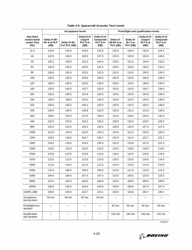
4-29
Table 4-9. Spacecraft Acoustic Test Levels
One-thirdoctave-bandcenter freq
(Hz)
Acceptance levels Protoflight and qualification levels
Delta IV-M/-M+ 4-m PLF
(dB)Delta IV-M+
5-m PLF (dB)
Delta IV-Hisogrid
PLF 5-m(dB)
Delta IV-Hcomposite
PLF 5-m(dB)
Delta IV-M/-M+ 4-mPLF (dB)
Delta IV-M+ 5-m
PLF (dB)
Delta IV-Hisogrid
PLF 5-m(dB)
Delta IV-Hcomposite
PLF 5-m(dB)
31.5 119.5 123.0 129.0 123.5 122.5 126.0 132.0 126.5
40 122.5 126.0 130.5 127.5 125.5 129.0 133.5 130.5
50 125.2 128.0 131.0 130.0 128.2 131.0 134.0 133.0
63 126.3 130.0 132.0 131.5 129.3 133.0 135.0 134.5
80 128.0 130.5 132.5 132.5 131.0 133.5 135.5 135.5
100 129.0 130.5 133.0 133.0 132.0 133.5 136.0 136.0
125 130.0 130.5 133.0 133.0 133.0 133.5 136.0 136.0
160 130.0 130.5 132.7 133.0 133.0 133.5 135.7 136.0
200 130.0 130.5 131.8 133.0 133.0 133.5 134.8 136.0
250 130.0 130.5 131.0 133.0 133.0 133.5 134.0 136.0
315 130.0 130.2 130.2 133.0 133.0 133.2 133.2 136.0
400 129.5 128.0 128.8 131.0 132.5 131.0 131.8 134.0
500 128.0 125.5 127.5 129.0 131.0 128.5 130.5 132.0
630 125.0 123.0 126.2 126.5 128.0 126.0 129.2 129.5
800 123.0 121.0 124.3 124.5 126.0 124.0 127.3 127.5
1000 121.0 119.5 122.5 122.5 124.0 122.5 125.5 125.5
1250 119.5 118.0 120.7 120.7 122.5 121.0 123.7 123.7
1600 118.0 116.5 118.3 118.3 121.0 119.5 121.3 121.3
2000 116.5 115.0 116.5 116.5 119.5 118.0 119.5 119.5
2500 115.0 113.5 115.0 115.0 118.0 116.5 118.0 118.0
3150 113.5 112.0 113.0 113.0 116.5 115.0 116.0 116.0
4000 112.0 110.0 111.5 111.5 115.0 113.0 114.5 114.5
5000 110.5 108.5 109.5 109.5 113.5 111.5 112.5 112.5
6300 109.0 106.5 107.5 107.5 112.0 109.5 110.5 110.5
8000 107.5 105.0 106.0 106.0 110.5 108.0 109.0 109.0
10000 106.0 103.0 104.0 104.0 109.0 106.0 107.0 107.0
OASPL (dB) 140.0 140.6 142.7 143.1 143.0 143.6 145.7 146.1
Acceptancetest duration
60 sec 60 sec 60 sec 60 sec --- --- --- ---
Protoflight testduration
--- --- --- --- 60 sec 60 sec 60 sec 60 sec
Qualificationtest duration
--- --- --- --- 120 sec 120 sec 120 sec 120 sec
001950.4
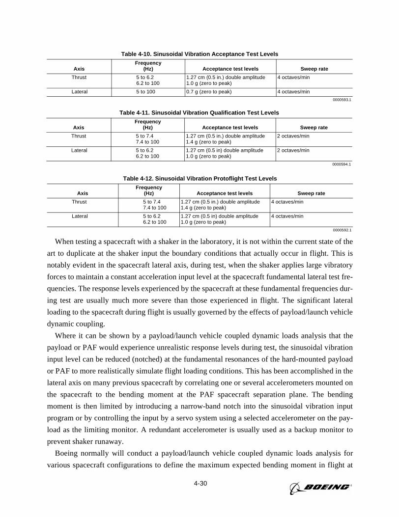
4-30
When testing a spacecraft with a shaker in the laboratory, it is not within the current state of the
art to duplicate at the shaker input the boundary conditions that actually occur in flight. This is
notably evident in the spacecraft lateral axis, during test, when the shaker applies large vibratory
forces to maintain a constant acceleration input level at the spacecraft fundamental lateral test fre-
quencies. The response levels experienced by the spacecraft at these fundamental frequencies dur-
ing test are usually much more severe than those experienced in flight. The significant lateral
loading to the spacecraft during flight is usually governed by the effects of payload/launch vehicle
dynamic coupling.
Where it can be shown by a payload/launch vehicle coupled dynamic loads analysis that the
payload or PAF would experience unrealistic response levels during test, the sinusoidal vibration
input level can be reduced (notched) at the fundamental resonances of the hard-mounted payload
or PAF to more realistically simulate flight loading conditions. This has been accomplished in the
lateral axis on many previous spacecraft by correlating one or several accelerometers mounted on
the spacecraft to the bending moment at the PAF spacecraft separation plane. The bending
moment is then limited by introducing a narrow-band notch into the sinusoidal vibration input
program or by controlling the input by a servo system using a selected accelerometer on the pay-
load as the limiting monitor. A redundant accelerometer is usually used as a backup monitor to
prevent shaker runaway.
Boeing normally will conduct a payload/launch vehicle coupled dynamic loads analysis for
various spacecraft configurations to define the maximum expected bending moment in flight at
Table 4-10. Sinusoidal Vibration Acceptance Test Levels
AxisFrequency
(Hz) Acceptance test levels Sweep rate
Thrust 5 to 6.26.2 to 100
1.27 cm (0.5 in.) double amplitude1.0 g (zero to peak)
4 octaves/min
Lateral 5 to 100 0.7 g (zero to peak) 4 octaves/min
0000593.1
Table 4-11. Sinusoidal Vibration Qualification Test Levels
AxisFrequency
(Hz) Acceptance test levels Sweep rate
Thrust 5 to 7.47.4 to 100
1.27 cm (0.5 in.) double amplitude1.4 g (zero to peak)
2 octaves/min
Lateral 5 to 6.26.2 to 100
1.27 cm (0.5 in) double amplitude1.0 g (zero to peak)
2 octaves/min
0000594.1
Table 4-12. Sinusoidal Vibration Protoflight Test Levels
AxisFrequency
(Hz) Acceptance test levels Sweep rate
Thrust 5 to 7.47.4 to 100
1.27 cm (0.5 in.) double amplitude1.4 g (zero to peak)
4 octaves/min
Lateral 5 to 6.26.2 to 100
1.27 cm (0.5 in) double amplitude1.0 g (zero to peak)
4 octaves/min
0000592.1
4-31
the spacecraft separation plane. In the absence of a specific dynamic analysis, the bending
moment is limited to protect the PAF, which is designed for a wide range of payload configura-
tions and weights. The payload user should consult Delta Launch Services before developing the
sinusoidal vibration test plan for information on the payload/launch vehicle coupled dynamic
loads analysis for that special mission or similar missions. In many cases, the notched sinusoidal
vibration test levels are established from previous similar analyses.
4.2.4.4 Shock Testing.High-frequency pyrotechnic shock levels are very difficult to simulate
mechanically on a shaker at the spacecraft system level. The most direct method for this testing is
to use a Delta IV flight configuration PAF spacecraft separation system and PAF structure with
functional ordnance devices. Payload qualification and protoflight shock testing are performed by
installing the in-flight configuration of the PAF spacecraft separation system and activating the
system twice. Spacecraft shock acceptance testing is similarly performed by activating the PAF
spacecraft separation system once.
4.2.5 Dynamic Analysis Criteria and Balance Requirements
4.2.5.1 Two-Stage Missions. Two-stage missions use the capability of the second stage to
provide terminal velocity, roll, final spacecraft orientation, and separation.
4.2.5.1.1 Spin Balance Requirements. For nonspinning spacecraft, no dynamic balance
constraint exists, but the static imbalance directly influences the spacecraft angular rates at sepa-
ration. When a separation tip-off constraint exists, the spacecraft center-of-gravity offset must be
coordinated with Delta Launch Services for evaluation.
4.2.5.1.2 Second-Stage Roll Rate Capability. For some two-stage missions, the space-
craft may require a roll rate at separation. The Delta IV second stage can command roll rates up
to 5 rpm (0.52 rad/s) using control jets. Higher roll rates are also possible; however, accuracy is
degraded as the rate increases. Roll rates higher than 5 rpm (0.52-rad/s) must be assessed relative
to specific spacecraft requirements.
5-1
Section 5
PAYLOAD INTERFACES
This section presents the detailed description of the mechanical interfaces between the payload
and the Delta IV launch vehicle family. Our Delta IV payload interfaces are designed to meet the
present and future demands of the global satellite market. Boeing utilizes a heritage design
approach for its payload attach fittings (PAFs); hence, unique interface requirements can be accom-
modated through a natural extension of a developed structure. Multiple payload dispenser systems
are also available; for further details coordinate directly with Delta Launch Services (DLS).
5.1 HERITAGE DESIGN PHILOSOPHY
Delta IV payload attach fittings are based on heritage designs that have been developed and
qualified by Boeing. This approach offers several advantages, primarily in reducing development
time and costs for new attach fittings.
5.1.1 Structural Design
The Delta IV PAFs utilize a structural design developed and successfully qualified on the
Delta III program. This heritage design evolved out of demand for a lighter weight structure with
minimal part count. Some of the key features include:
High-modulus graphite-epoxy/foam core sandwich construction for the conic shell.
One-piece aluminum rings at each end for interfaces to the second stage and payload.
Efficient double-splice lap joints to join end rings to conic shell.
High-modulus graphite-epoxy/foam core sandwich diaphragm structure that provides a barrier
to the second stage.
This design is easily adapted to accommodate different interface diameters and payload sizes
simply by extending/contracting the conic shell and sizing the sandwich structure and end-ring
design. As a result, much of the secondary structure developed for one PAF is readily adapted to
another.
The PAF for the evolved expendable launch vehicle (EELV) 5-m metallic fairing missions
adopts a different heritage design. This PAF makes use of a heritage truss structure design devel-
oped and flown by Boeing Space Structures in Kent, Washington. The design’s extensive use of
advanced composite materials, lightweight materials, and bonded structures fits well with the key
objectives for this particular PAF.
5.1.2 Mechanical Design
Boeing has extensive flight experience with both Marmon-type clampband and discrete bolted
interface separation systems. Delta II and Delta III have developed and flown Marmon-type
clampbands over a broad range of diameters, 229 mm (9 in.) to 1666 mm (66-in.). In addition,
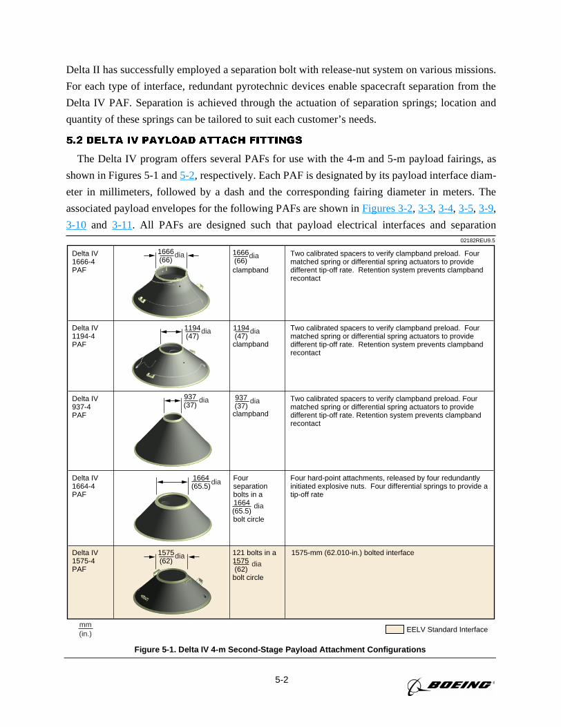
5-2
Delta II has successfully employed a separation bolt with release-nut system on various missions.
For each type of interface, redundant pyrotechnic devices enable spacecraft separation from the
Delta IV PAF. Separation is achieved through the actuation of separation springs; location and
quantity of these springs can be tailored to suit each customer’s needs.
5.2 DELTA IV PAYLOAD ATTACH FITTINGS
The Delta IV program offers several PAFs for use with the 4-m and 5-m payload fairings, as
shown in Figures 5-1 and5-2, respectively. Each PAF is designated by its payload interface diam-
eter in millimeters, followed by a dash and the corresponding fairing diameter in meters. The
associated payload envelopes for the following PAFs are shown inFigures 3-2, 3-3, 3-4, 3-5, 3-9,
3-10 and 3-11. All PAFs are designed such that payload electrical interfaces and separation02182REU9.5
EELV Standard Interfacemm(in.)
dia
Delta IV 1666-4PAF
dia1666(66)clampband
1666(66)
dia
Delta IV 1194-4PAF
1194(47)
dia
clampband
1194(47)
dia
Delta IV 937-4PAF
937(37)
dia
clampband
937(37)
dia
Delta IV 1664-4PAF
1664(65.5)
dia
Fourseparationbolts in a
bolt circle
1664(65.5)
dia
121 bolts in a1575 (62)bolt circle
Delta IV 1575-4PAF
1575(62)
dia
Two calibrated spacers to verify clampband preload. Four matched spring or differential spring actuators to provide different tip-off rate. Retention system prevents clampbandrecontact
1575-mm (62.010-in.) bolted interface
Four hard-point attachments, released by four redundantly initiated explosive nuts. Four differential springs to provide a tip-off rate
Two calibrated spacers to verify clampband preload. Four matched spring or differential spring actuators to provide different tip-off rate. Retention system prevents clampbandrecontact
Two calibrated spacers to verify clampband preload. Four matched spring or differential spring actuators to provide different tip-off rate. Retention system prevents clampband recontact
Figure 5-1. Delta IV 4-m Second-Stage Payload Attachment Configurations
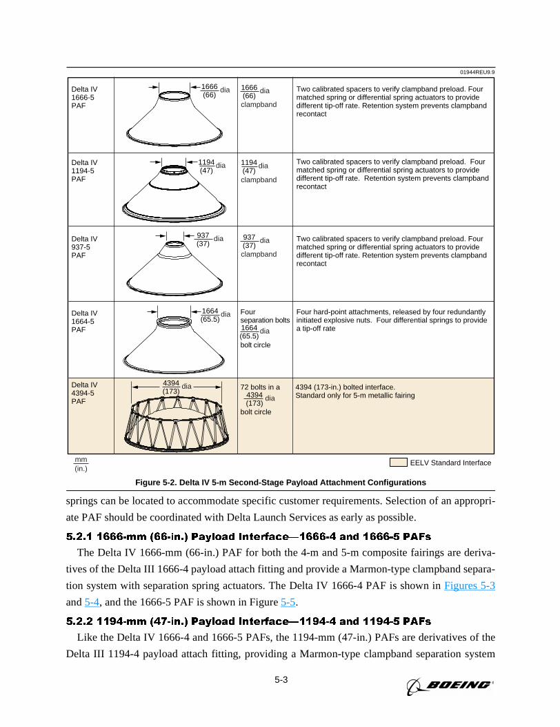
5-3
springs can be located to accommodate specific customer requirements. Selection of an appropri-
ate PAF should be coordinated with Delta Launch Services as early as possible.
5.2.1 1666-mm (66-in.) Payload Interface—1666-4 and 1666-5 PAFs
The Delta IV 1666-mm (66-in.) PAF for both the 4-m and 5-m composite fairings are deriva-
tives of the Delta III 1666-4 payload attach fitting and provide a Marmon-type clampband separa-
tion system with separation spring actuators. The Delta IV 1666-4 PAF is shown inFigures 5-3
and5-4, and the 1666-5 PAF is shown in Figure5-5.
5.2.2 1194-mm (47-in.) Payload Interface—1194-4 and 1194-5 PAFs
Like the Delta IV 1666-4 and 1666-5 PAFs, the 1194-mm (47-in.) PAFs are derivatives of the
Delta III 1194-4 payload attach fitting, providing a Marmon-type clampband separation system
Delta IV4394-5PAF
72 bolts in a
bolt circle
Two calibrated spacers to verify clampband preload. Four matched spring or differential spring actuators to provide different tip-off rate. Retention system prevents clampbandrecontact
4394 (173-in.) bolted interface.Standard only for 5-m metallic fairing
Four hard-point attachments, released by four redundantly initiated explosive nuts. Four differential springs to provide a tip-off rate
Fourseparation bolts
bolt circle
Two calibrated spacers to verify clampband preload. Four matched spring or differential spring actuators to provide different tip-off rate. Retention system prevents clampband recontact
Delta IV1194-5PAF
Delta IV1664-5PAF
Delta IV1666-5PAF
EELV Standard Interface
01944REU9.9
mm(in.)
4394(173)
dia
1194(47)
dia 1194(47)
dia
1664(65.5)
dia
4394(173)
dia
1664(65.5)
dia
1666(66)
dia1666(66)
dia
937(37)
dia
clampband
Two calibrated spacers to verify clampband preload. Four matched spring or differential spring actuators to provide different tip-off rate. Retention system prevents clampband recontact
Delta IV937-5PAF
937(37)
dia
clampband
clampband
Figure 5-2. Delta IV 5-m Second-Stage Payload Attachment Configurations
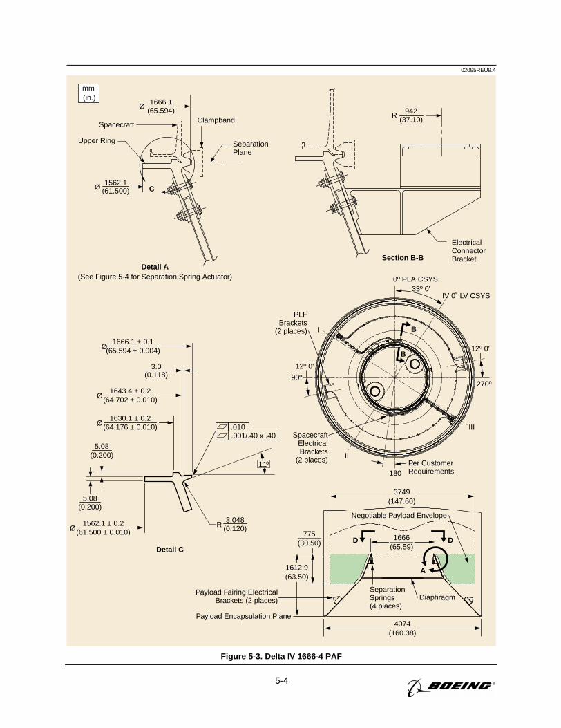
5-4
02095REU9.4
3749(147.60)
1666(65.59)
775(30.50)
Section B-B
ElectricalConnectorBracket
942(37.10)
R
mm(in.)
Detail A(See Figure 5-4 for Separation Spring Actuator)
Payload Encapsulation Plane
180
270º90º
33º 0'
Per CustomerRequirements
SpacecraftElectricalBrackets
(2 places)
PLFBrackets
(2 places)
12º 0'
12º 0'
0º PLA CSYS
IV 0˚ LV CSYS
III
II
I
D
B
B
A
D
Payload Fairing ElectricalBrackets (2 places)
SeparationSprings(4 places)
Negotiable Payload Envelope
Diaphragm
1666.1(65.594)
Upper Ring
SpacecraftClampband
SeparationPlane
Ø
Ø
Ø
1562.1(61.500) C
Detail C
(65.594 ± 0.004)1666.1 ± 0.1
Ø(64.176 ± 0.010)1630.1 ± 0.2
Ø(61.500 ± 0.010)1562.1 ± 0.2
Ø(64.702 ± 0.010)1643.4 ± 0.2
5.08(0.200)
5.08(0.200)
R3.048
(0.120)
.010
.001/.40 x .40
4074(160.38)
1612.9(63.50)
3.0(0.118)
11º
Figure 5-3. Delta IV 1666-4 PAF
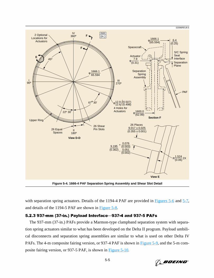
5-5
with separation spring actuators. Details of the 1194-4 PAF are provided inFigures 5-6and5-7,
and details of the 1194-5 PAF are shown inFigure 5-8.
5.2.3 937-mm (37-in.) Payload Interface—937-4 and 937-5 PAFs
The 937-mm (37-in.) PAFs provide a Marmon-type clampband separation system with separa-
tion spring actuators similar to what has been developed on the Delta II program. Payload umbili-
cal disconnects and separation spring assemblies are similar to what is used on other Delta IV
PAFs. The 4-m composite fairing version, or 937-4 PAF is shown inFigure 5-9, and the 5-m com-
posite fairing version, or 937-5 PAF, is shown inFigure 5-10.
02096REU9.5
mm(in.)
SeparationPlane
S/C SpringSeatInterface
PAF
1666.1(65.594)
φ
Spacecraft
SeparationSpring
Assembly
7.9(0.31)
φ
Actuator
1600.0(62.99)
φ
2 OptionalLocations for
Actuators
IV360º
III270º
II180º
I90º
67˚30'
22º 30'
26 ShearPin Slots
45ºE
Upper Ring
1666.165.594
φ
26 EqualSpaces
12.912.6φ
4 Holes forActuators
Section F
View D-D
2X1.524(0.06)R
9.195(0.362)
0.076(0.003)
+
0.051(0.002)
–
9.017 ± 0.025(0.355 ± 0.001)
26 Places
6.4(0.25)
F
F
View E
(0.507)(0.498)
Figure 5-4. 1666-4 PAF Separation Spring Assembly and Shear Slot Detail
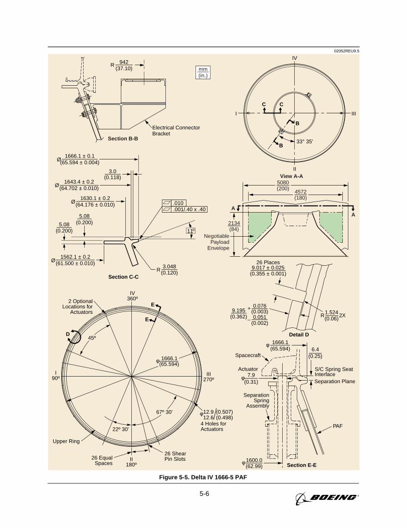
5-6
02052REU9.5
mm(in.)
View A-A
Section B-B
AA
4572(180)
5080(200)
Electrical ConnectorBracket
942(37.10)
R
Separation Plane
S/C Spring SeatInterface
PAF
1666.1(65.594)
φ
Spacecraft
SeparationSpring
Assembly
7.9(0.31)
φ
Actuator
1600.0(62.99)
φ Section E-E
6.4(0.25)
2 OptionalLocations for
Actuators
26 ShearPin Slots
Upper Ring
26 EqualSpaces
12.912.6
φ
4 Holes forActuators
(0.507)(0.498)
Section C-C
3.0(0.118)
5.08(0.200)5.08
(0.200)
R3.048
(0.120)
.010
.001/.40 x .40
2X1.524(0.06)
R9.195
(0.362)
0.076(0.003)
+
0.051(0.002)
–
9.017 ± 0.025(0.355 ± 0.001)
26 Places
Detail D
II
B
IIII
IV
33° 35'
B
CC
NegotiablePayload
Envelope
2134(84)
Ø(64.702 ± 0.010)1643.4 ± 0.2
Ø(65.594 ± 0.004)1666.1 ± 0.1
Ø(64.176 ± 0.010)1630.1 ± 0.2
Ø(61.500 ± 0.010)1562.1 ± 0.2
E
D
E
1666.1(65.594)
φ
67º 30'
22º 30'
45º
IV360º
III270º
II180º
I90º
11º
Figure 5-5. Delta IV 1666-5 PAF
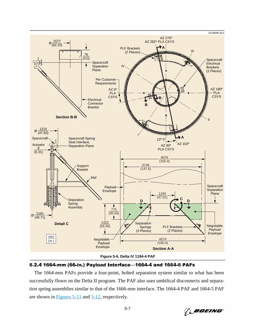
5-7
D D
Section A-A
Section B-B
C
Detail C
NegotiablePayload
Envelope
SeparationSpringAssembly
Spacecraft Spacecraft SpringSeat Interface,Separation Plane
ElectricalConnectorBracket
PayloadEnvelope
SpacecraftSeparationPlane
SpacecraftElectricalBrackets(2 Places)
AZ 180ºPLA
CSYS
AZ 270ºPLA CSYS
III
II
I
IV
AZ 90ºPLA CSYS
AZ 102º12º 0'
AZ 282º
AZ 0ºPLA
CSYS
SupportBracket
PAF
SpacecraftSeparation
Plane
SeparationSprings
(4 Places)
PLF Brackets(2 Places)
Per CustomerRequirements
3749(147.6)
4074(160.4)
4074(160.4)
mm(in.)
1194(47.01)
B
B
A
A
02180REU9.4
1215(47.83)
Ø
1577(62.10)
Ø
1161(45.71)
Ø
8(0.31)
76(3.0)
775(30.50)
1422(56.00)
Actuator
PLF Brackets(2 Places)
NegotiablePayload
Envelope
Figure 5-6. Delta IV 1194-4 PAF
5.2.4 1664-mm (66-in.) Payload Interface—1664-4 and 1664-5 PAFs
The 1664-mm PAFs provide a four-point, bolted separation system similar to what has been
successfully flown on the Delta II program. The PAF also uses umbilical disconnects and separa-
tion spring assemblies similar to that of the 1666-mm interface. The 1664-4 PAF and 1664-5 PAF
are shown inFigures 5-11and5-12, respectively.
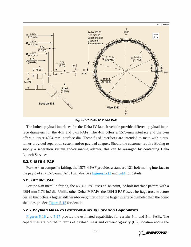
5-8
The bolted payload interfaces for the Delta IV launch vehicle provide different payload inter-
face diameters for the 4-m and 5-m PAFs. The 4-m offers a 1575-mm interface and the 5-m
offers a larger 4394-mm interface dia. These fixed interfaces are intended to mate with a cus-
tomer-provided separation system and/or payload adapter. Should the customer require Boeing to
supply a separation system and/or mating adapter, this can be arranged by contacting Delta
Launch Services.
5.2.5 1575-4 PAF
For the 4-m composite fairing, the 1575-4 PAF provides a standard 121-bolt mating interface to
the payload at a 1575-mm (62.01 in.) dia. SeeFigures 5-13and5-14for details.
5.2.6 4394-5 PAF
For the 5-m metallic fairing, the 4394-5 PAF uses an 18-point, 72-bolt interface pattern with a
4394-mm (173-in.) dia. Unlike other Delta IV PAFs, the 4394-5 PAF uses a heritage truss structure
design that offers a higher stiffness-to-weight ratio for the larger interface diameter than the conic
shell design. SeeFigure 5-15for details.
5.2.7 Payload Mass vs Center-of-Gravity Location Capabilities
Figures 5-16and5-17 provide the estimated capabilities for certain 4-m and 5-m PAFs. The
capabilities are plotted in terms of payload mass and center-of-gravity (CG) location above the
02181REU9.6
1184(46.614)
Section E-EView D-D
2.54(0.100)
E E
Ø
I90º
II180º
III270º
24 by 15º 0'Sep SpringLocations perCustomerRequirements
IV0º
1195(47.047)
Ø
1209(47.605)
Ø
1215(47.835)
Ø
35(1.378)
4(0.157)
21.69(0.854)
1.3(0.05)
1209.2(47.605)
Ø1161.0(45.710)
Ø
1215.0(47.835)
Ø
mm(in.)
9º
Figure 5-7. Delta IV 1194-4 PAF
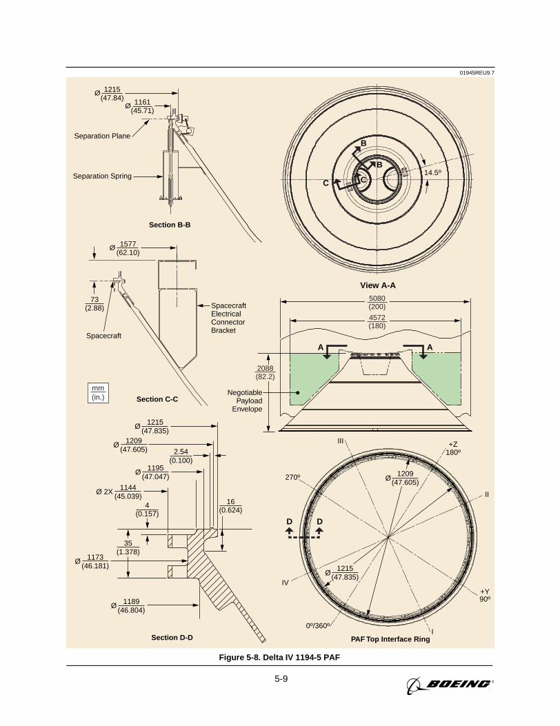
5-9
01945REU9.7
1144(45.039)
4
A
View A-A
Section B-B
PAF Top Interface Ring
B14.5º
CC
B
A
NegotiablePayload
Envelope
5080(200)
2088(82.2)
4572(180)
1161(45.71)
1215(47.84)
Separation Plane
Separation Spring
D D
SpacecraftElectricalConnectorBracket
Spacecraft
Section C-C
Ø
1577(62.10)
Ø
73(2.88)
Ø
III
270º
IV
0º/360ºI
+Y90º
II
+Z180º
(0.157)
(0.100)
Ø 2X
Section D-D
mm(in.)
Ø
1215(47.835)
35(1.378)
Ø
1209(47.605)
Ø
1215(47.835)
Ø 1209(47.605)
Ø 1173(46.181)
Ø 1189(46.804)
Ø 1195(47.047)
16(0.624)
2.54
Figure 5-8. Delta IV 1194-5 PAF
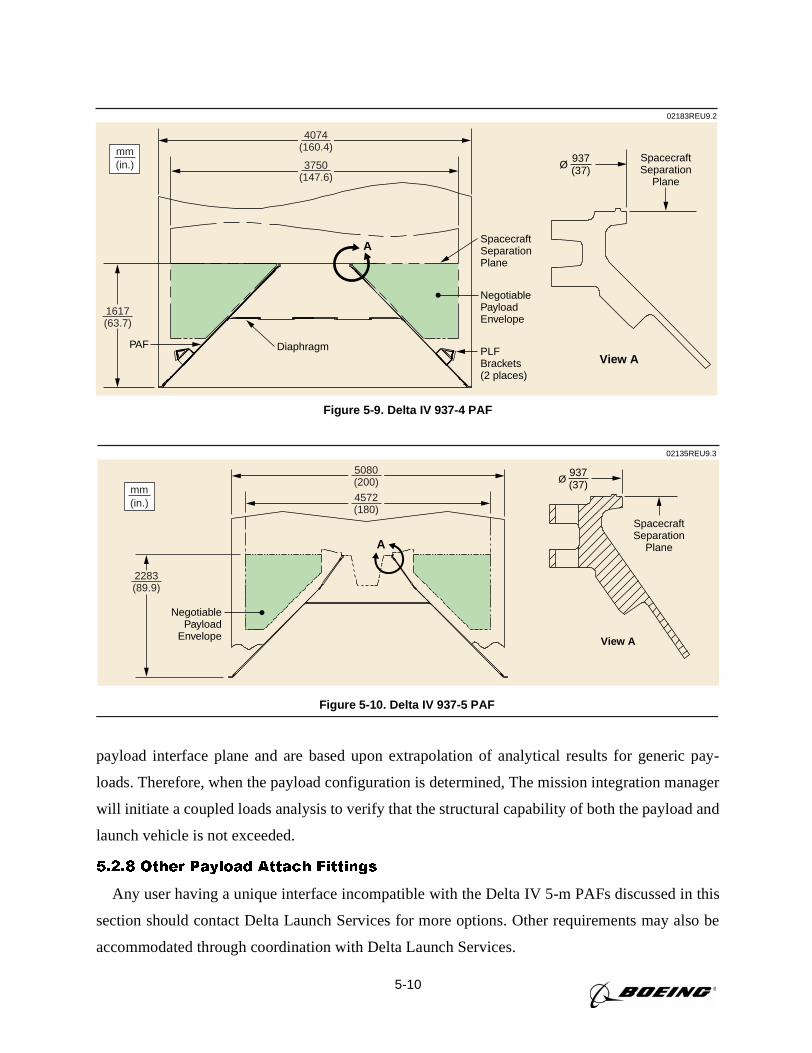
5-10
View A
A
NegotiablePayloadEnvelope
SpacecraftSeparation
Plane
SpacecraftSeparationPlane
PLFBrackets(2 places)
DiaphragmPAF
4074(160.4)
1617(63.7)
mm(in.) 3750
(147.6)
02183REU9.2
937(37)Ø
Figure 5-9. Delta IV 937-4 PAF
A
NegotiablePayload
Envelope
SpacecraftSeparation
Plane
View A
mm(in.)
5080(200)
4572(180)
02135REU9.3
937(37)Ø
2283(89.9)
Figure 5-10. Delta IV 937-5 PAF
payload interface plane and are based upon extrapolation of analytical results for generic pay-
loads. Therefore, when the payload configuration is determined, The mission integration manager
will initiate a coupled loads analysis to verify that the structural capability of both the payload and
launch vehicle is not exceeded.
5.2.8 Other Payload Attach Fittings
Any user having a unique interface incompatible with the Delta IV 5-m PAFs discussed in this
section should contact Delta Launch Services for more options. Other requirements may also be
accommodated through coordination with Delta Launch Services.
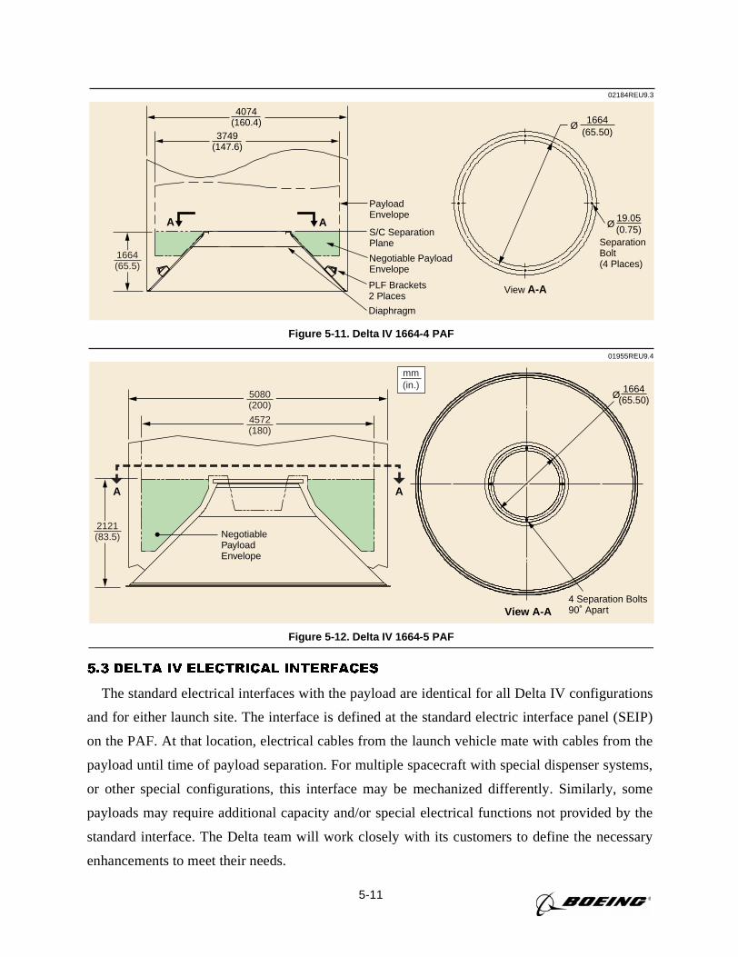
5-11
5.3 DELTA IV ELECTRICAL INTERFACES
The standard electrical interfaces with the payload are identical for all Delta IV configurations
and for either launch site. The interface is defined at the standard electric interface panel (SEIP)
on the PAF. At that location, electrical cables from the launch vehicle mate with cables from the
payload until time of payload separation. For multiple spacecraft with special dispenser systems,
or other special configurations, this interface may be mechanized differently. Similarly, some
payloads may require additional capacity and/or special electrical functions not provided by the
standard interface. The Delta team will work closely with its customers to define the necessary
enhancements to meet their needs.
02184REU9.3
S/C SeparationPlane
3749(147.6)
PayloadEnvelope
PLF Brackets2 Places
4074(160.4)
A A
Diaphragm
Negotiable PayloadEnvelope
1664(65.50)
Ø
19.05(0.75)
Ø
SeparationBolt(4 Places)
View A-A
1664(65.5)
Figure 5-11. Delta IV 1664-4 PAF
A
View A-A
NegotiablePayloadEnvelope
4 Separation Bolts90˚ Apart
5080(200)
mm(in.)
4572(180)
A
01955REU9.4
1664(65.50)Ø
2121(83.5)
Figure 5-12. Delta IV 1664-5 PAF
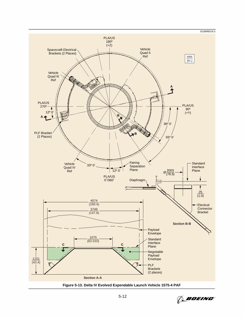
5-12
02186REU9.3
Section A-A
Section B-B
C C
1101(43.4)
PLA/US180º(+Z)
VehicleQuad II
Ref
VehicleQuad III
Ref
VehicleQuad IV
Ref
PLA/US90º(+Y)
PLA/US270º
PLA/US0˚/360˚
A
B
B
A
PayloadEnvelope
mm(in.)
2003(78.9)
25(1.0)
Ø
NegotiablePayloadEnvelope
ElecticalConnectorBracket
StandardInterfacePlane
FairingSeparationPlane
StandardInterfacePlane
Spacecraft ElectricalBrackets (2 Places)
PLF Bracket(2 Places)
Diaphragm
PLFBrackets(2 places)
4074(160.4)
3749(147.6)
1575(62.010)
36º 0'
33º 0'
12º 0'
12º 0'
55º 0'
Figure 5-13. Delta IV Evolved Expendable Launch Vehicle 1575-4 PAF
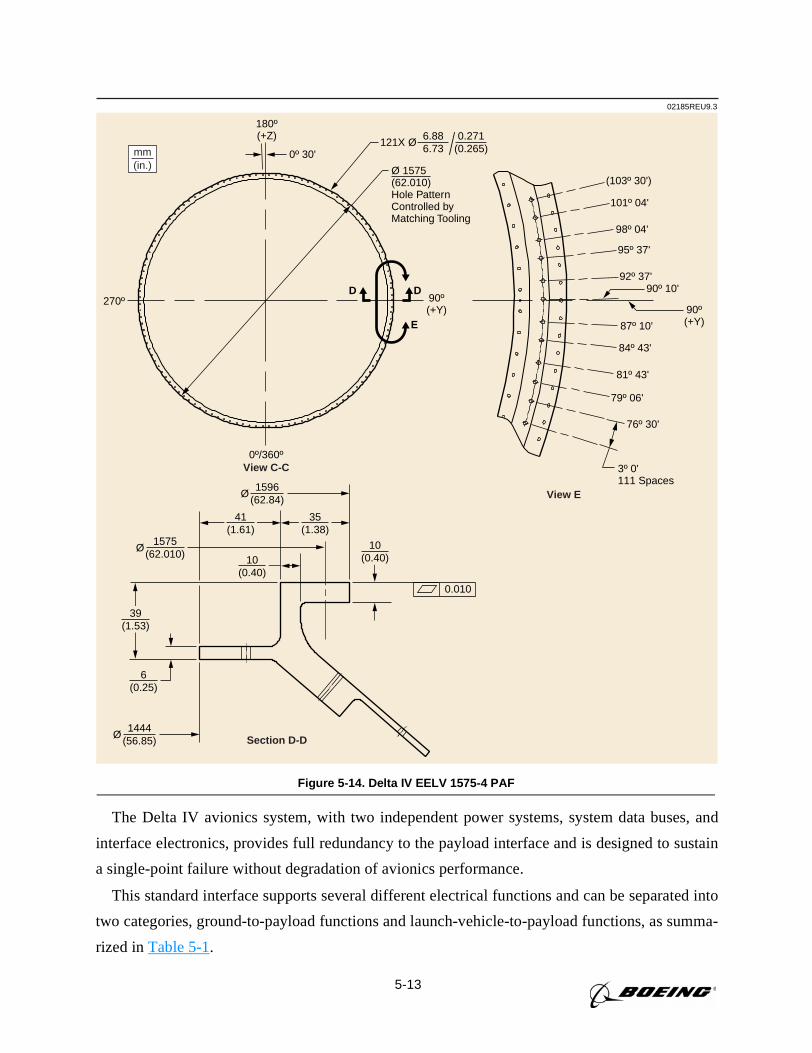
5-13
The Delta IV avionics system, with two independent power systems, system data buses, and
interface electronics, provides full redundancy to the payload interface and is designed to sustain
a single-point failure without degradation of avionics performance.
This standard interface supports several different electrical functions and can be separated into
two categories, ground-to-payload functions and launch-vehicle-to-payload functions, as summa-
rized inTable 5-1.
02185REU9.3
View C-C
View E
Section D-D
270º
180º(+Z)
0º 30'
90º(+Y) 90º
(+Y)
(103º 30')
101º 04'
98º 04'
95º 37'
92º 37'
87º 10'
84º 43'
81º 43'
79º 06'
76º 30'
3º 0'111 Spaces
90º 10'
Ø 1575(62.010)Hole PatternControlled byMatching Tooling
121X Ø0.271
(0.265)
0º/360º
D
E
D
6.886.73
0.010
1596(62.84)
Ø
1575(62.010)
Ø
1444(56.85)
Ø
41(1.61)
39(1.53)
6(0.25)
10(0.40)
35(1.38)
10(0.40)
mm(in.)
Figure 5-14. Delta IV EELV 1575-4 PAF
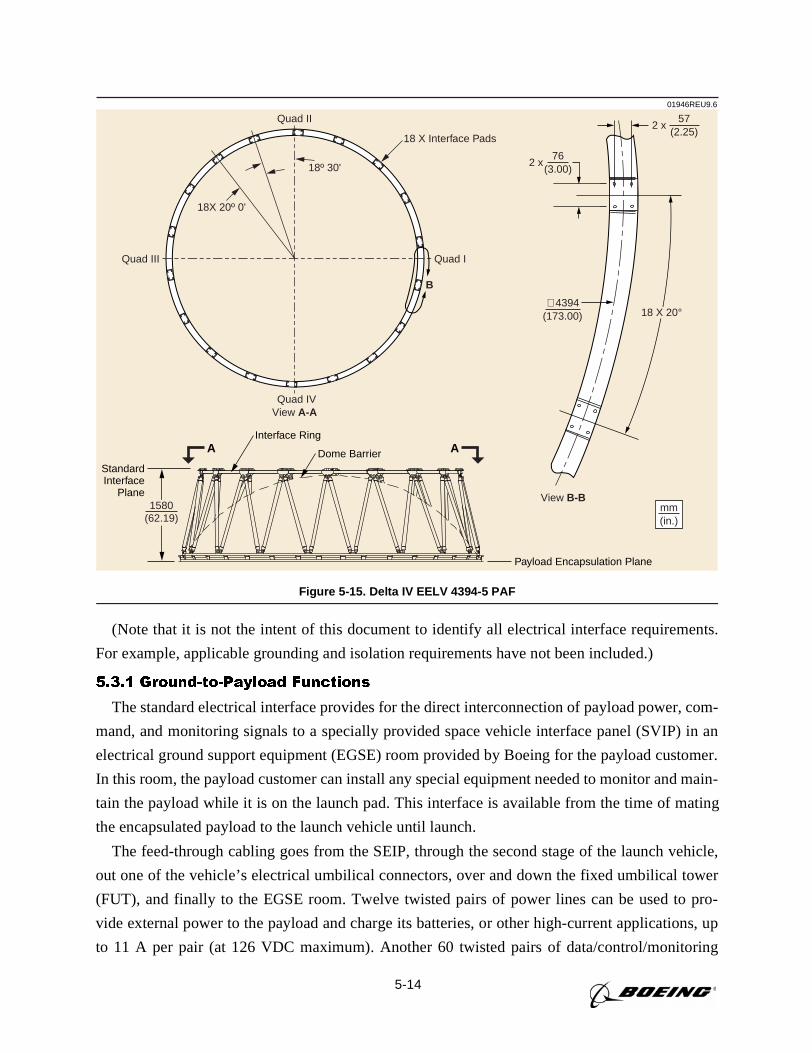
5-14
(Note that it is not the intent of this document to identify all electrical interface requirements.
For example, applicable grounding and isolation requirements have not been included.)
5.3.1 Ground-to-Payload Functions
The standard electrical interface provides for the direct interconnection of payload power, com-
mand, and monitoring signals to a specially provided space vehicle interface panel (SVIP) in an
electrical ground support equipment (EGSE) room provided by Boeing for the payload customer.
In this room, the payload customer can install any special equipment needed to monitor and main-
tain the payload while it is on the launch pad. This interface is available from the time of mating
the encapsulated payload to the launch vehicle until launch.
The feed-through cabling goes from the SEIP, through the second stage of the launch vehicle,
out one of the vehicle’s electrical umbilical connectors, over and down the fixed umbilical tower
(FUT), and finally to the EGSE room. Twelve twisted pairs of power lines can be used to pro-
vide external power to the payload and charge its batteries, or other high-current applications, up
to 11 A per pair (at 126 VDC maximum). Another 60 twisted pairs of data/control/monitoring
01946REU9.6
Payload Encapsulation Plane
StandardInterface
Plane
Interface Ring
Dome BarrierA A
1580(62.19)
mm(in.)
∅4394
View A-A
View B-B
(173.00)
(3.00)76
2 x
(2.25)57
2 x
18 X 20°
18 X Interface Pads
B
Quad III Quad I
Quad II
18º 30'
18X 20º 0'
Quad IV
Figure 5-15. Delta IV EELV 4394-5 PAF
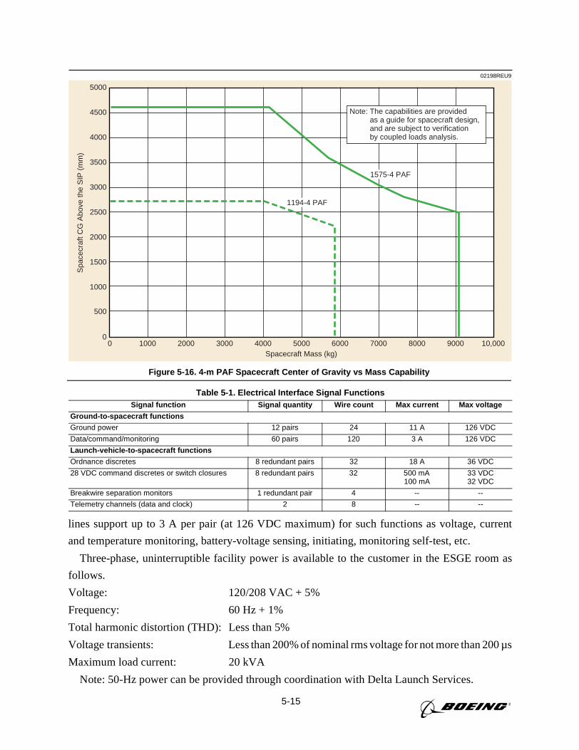
5-15
lines support up to 3 A per pair (at 126 VDC maximum) for such functions as voltage, current
and temperature monitoring, battery-voltage sensing, initiating, monitoring self-test, etc.
Three-phase, uninterruptible facility power is available to the customer in the ESGE room as
follows.
Voltage: 120/208 VAC + 5%
Frequency: 60 Hz + 1%
Total harmonic distortion (THD): Less than 5%
Voltage transients: Less than 200% of nominal rms voltage for not more than 200 µs
Maximum load current: 20 kVA
Note: 50-Hz power can be provided through coordination with Delta Launch Services.
02198REU9
5000
4500
4000
3500
3000
2500
2000
1500
1000
500
Spa
cecr
aft C
G A
bove
the
SIP
(m
m)
Spacecraft Mass (kg)0 1000 2000 3000 4000 5000 6000 7000 8000 9000 10,000
0
Note: The capabilities are providedas a guide for spacecraft design,and are subject to verificationby coupled loads analysis.
1194-4 PAF
1575-4 PAF
Figure 5-16. 4-m PAF Spacecraft Center of Gravity vs Mass Capability
Table 5-1. Electrical Interface Signal FunctionsSignal function Signal quantity Wire count Max current Max voltage
Ground-to-spacecraft functions
Ground power 12 pairs 24 11 A 126 VDC
Data/command/monitoring 60 pairs 120 3 A 126 VDC
Launch-vehicle-to-spacecraft functions
Ordnance discretes 8 redundant pairs 32 18 A 36 VDC
28 VDC command discretes or switch closures 8 redundant pairs 32 500 mA100 mA
33 VDC32 VDC
Breakwire separation monitors 1 redundant pair 4 -- --
Telemetry channels (data and clock) 2 8 -- --
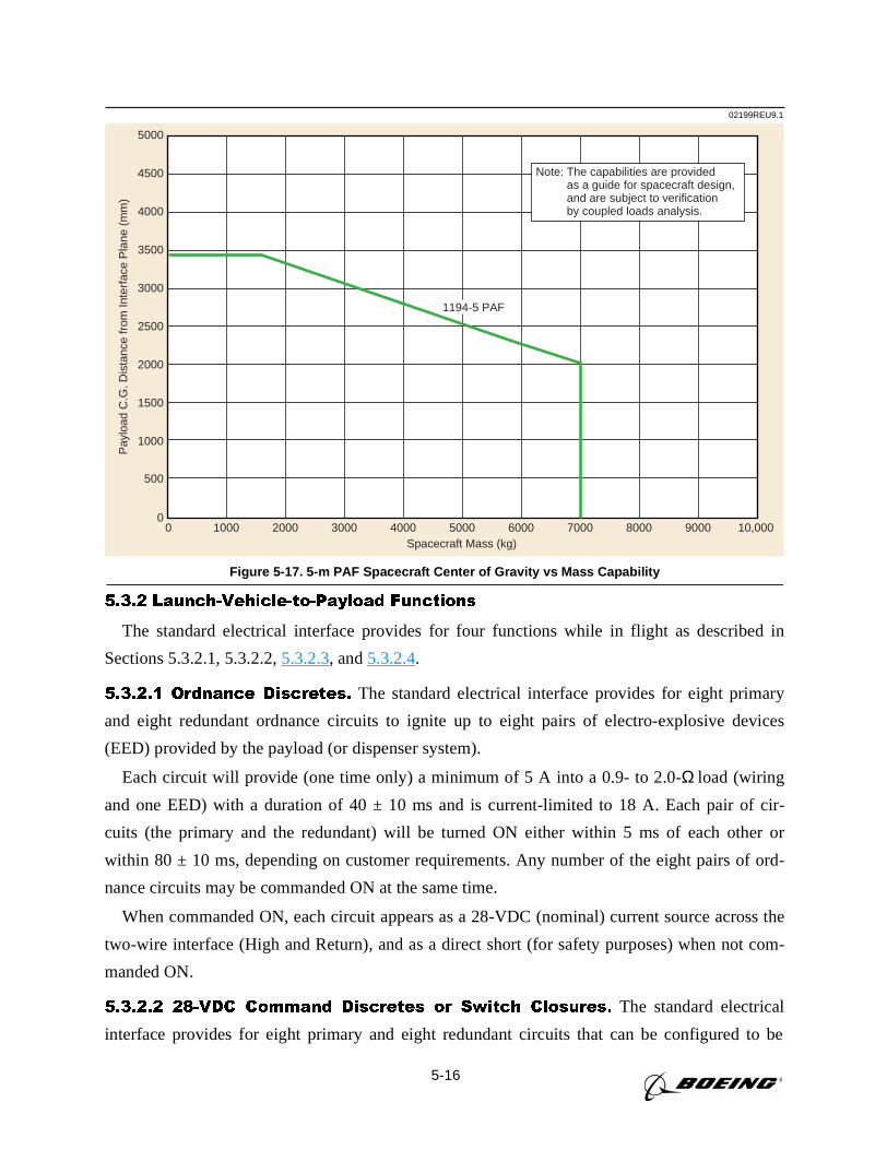
5-16
5.3.2 Launch-Vehicle-to-Payload Functions
The standard electrical interface provides for four functions while in flight as described in
Sections 5.3.2.1, 5.3.2.2,5.3.2.3, and5.3.2.4.
5.3.2.1 Ordnance Discretes. The standard electrical interface provides for eight primary
and eight redundant ordnance circuits to ignite up to eight pairs of electro-explosive devices
(EED) provided by the payload (or dispenser system).
Each circuit will provide (one time only) a minimum of 5 A into a 0.9- to 2.0-Ω load (wiring
and one EED) with a duration of 40 ± 10 ms and is current-limited to 18 A. Each pair of cir-
cuits (the primary and the redundant) will be turned ON either within 5 ms of each other or
within 80 ± 10 ms, depending on customer requirements. Any number of the eight pairs of ord-
nance circuits may be commanded ON at the same time.
When commanded ON, each circuit appears as a 28-VDC (nominal) current source across the
two-wire interface (High and Return), and as a direct short (for safety purposes) when not com-
manded ON.
5.3.2.2 28-VDC Command Discretes or Switch Closures. The standard electrical
interface provides for eight primary and eight redundant circuits that can be configured to be
02199REU9.1P
aylo
ad C
.G. D
ista
nce
from
Inte
rfac
e P
lane
(m
m)
5000
4500
4000
3500
3000
2500
2000
1500
1000
500
Spacecraft Mass (kg)0 1000 2000 3000 4000 5000 6000 7000 8000 9000 10,000
0
Note: The capabilities are providedas a guide for spacecraft design,and are subject to verificationby coupled loads analysis.
1194-5 PAF
Figure 5-17. 5-m PAF Spacecraft Center of Gravity vs Mass Capability
5-17
either 28-VDC command discretes or switch closures, depending on customer needs (all circuits
must be configured in the same way).
If the circuits are configured as 28-VDC command discretes, the two-wire (High and Return)
avionics circuits will provide the payload with up to 500 mA with a voltage of 23 to 33 VDC when
commanded ON. When configured as switch closures, the two-wire (In and Out) avionics circuits
will act as a solid-state relay and support the passage of up to 1 A at a voltage of 22 to 32 VDC
when commanded ON (when OFF, the leakage current shall be less than 1 mA).
In either case, the circuits can be commanded in any sequence with up to ten changes in state
(ON/OFF) for each circuit, but each commanded duration must be between 20 ms and 10 sec.
Hence, each circuit may not be ON for a cumulative time of greater than 50 sec.
5.3.2.3 Breakwire Separation Monitors. The standard electrical interface provides for
one pair of redundant separation monitor circuits. Typically, the payload provides a shorting
jumper on its side of the circuit, and the avionics detects an open circuit when separation occurs.
The jumper (and any wiring) in the payload must present less than 1Ω before separation, and the
circuit must open or be greater than 1 MΩ after separation.
If there is more than one payload and monitoring of each is required, the customer should
request that additional pairs of monitors be provided.
5.3.2.4 Telemetry Channels. The standard electrical interface provides for two telemetry
channels, each capable of receiving up to 2 kBps of data, but not both at the same time.
Each avionics channel consists of two RS-422 differential line receivers, one for data (non-
return-to-zero—phase L) and one for the clock. Data is sampled on the FALSE-to-TRUE transi-
tion of the clock.
5.3.3 Spacecraft Connectors. TBD
5.3.4 Customer Wiring Documentation
To ensure proper attention to the customer’s needs, information regarding customer wiring
documentation, which is contained inSection 8, Table 8-4, Delta IV Spacecraft Questionnaire,
shall be furnished by the customer.
6-1
Section 6
LAUNCH OPERATIONS AT EASTERN RANGE
This section presents a description of Delta launch vehicle operations associated with Space
Launch Complex 37 (SLC-37) at Cape Canaveral Air Station, (CCAS) Florida. Delta IV pre-
launch processing and spacecraft operations conducted prior to launch are presented.
6.1 ORGANIZATIONS
Boeing operates the Delta launch system and maintains a team that provides launch services to
the USAF, NASA, and commercial customers at CCAS. Boeing provides the interface to the Fed-
eral Aviation Administration (FAA) and the Department of Transportation (DOT) for the licens-
ing and certification needed to launch commercial payloads using Delta IV.
Boeing has an established interface with the USAF 45th Space Wing Directorate of Plans. The
USAF designates a program support manager (PSM) to be a representative of the 45th Space
Wing. The PSM serves as the official interface for all USAF support and services requested.
These services include range instrumentation, facilities/equipment operation and maintenance,
and safety, security, and logistics support. Requirements for range services are described in docu-
ments prepared and submitted to the government by Boeing, based on inputs from the spacecraft
contractor, using the government's universal documentation system (UDS) format (seeSection 8,
Payload Integration). The organizations that support a launch are shown inFigure 6-1. For each
mission, a spacecraft coordinator from the Boeing CCAS launch team is assigned to assist the
spacecraft team during the launch campaign by helping to obtain safety approval of the payload
test procedures and operations, integrating the spacecraft operations into the launch vehicle activ-
ities, and serving as the interface between the payload and test conductor in the launch control
center during the countdown and launch. Boeing interfaces with NASA at Kennedy Space Center
(KSC) through the Expendable Launch Vehicle and Payload Carriers Program Office. NASA des-
ignates a launch service integration manager who arranges all of the support requested from
NASA for a launch from CCAS.
Boeing also has an established working relationship with Astrotech Space Operations. Astro-
tech owns and operates a processing facility for commercial payloads in Titusville, Florida, in
support of Delta missions. Use of these facilities and services may be arranged by Boeing for the
customer.
6.2 FACILITIES
In addition to the facilities required for the Delta IV launch vehicles, specialized payload pro-
cessing facilities (PPFs) listed below are provided for checkout and preparation of government
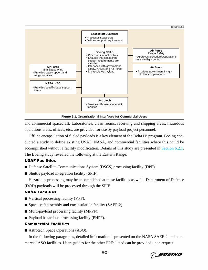
6-2
and commercial spacecraft. Laboratories, clean rooms, receiving and shipping areas, hazardous
operations areas, offices, etc., are provided for use by payload project personnel.
Offline encapsulation of fueled payloads is a key element of the Delta IV program. Boeing con-
ducted a study to define existing USAF, NASA, and commercial facilities where this could be
accomplished without a facility modification. Details of this study are presented inSection 6.2.1.
The Boeing study revealed the following at the Eastern Range:
USAF Facilities
Defense Satellite Communications System (DSCS) processing facility (DPF).
Shuttle payload integration facility (SPIF).
Hazardous processing may be accomplished at these facilities as well. Department of Defense
(DOD) payloads will be processed through the SPIF.
NASA Facilities
Vertical processing facility (VPF).
Spacecraft assembly and encapsulation facility (SAEF-2).
Multi-payload processing facility (MPPF).
Payload hazardous processing facility (PHPF).
Commercial Facilities
Astrotech Space Operations (ASO).
In the following paragraphs, detailed information is presented on the NASA SAEF-2 and com-
mercial ASO facilities. Users guides for the other PPFs listed can be provided upon request.
02058REU9.2
Air Force45th Space Wing
• Provides base support and range services
NASA KSC
• Provides specific base support items
Air ForceRange Safety
• Approves procedures/operations • missile flight control
Air Force
• Provides government insightinto launch operations
Spacecraft Customer• Processes spacecraft• Defines support requirements
Boeing CCAS• Processes launch vehicle• Ensures that spacecraft
support requirements aresatisfied
• Interfaces with government,safety, NASA, and Air Force
• Encapsulates payload
Astrotech• Provides off-base spacecraft facilities
Figure 6-1. Organizational Interfaces for Commercial Users
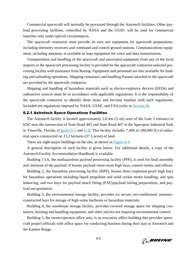
6-3
Commercial spacecraft will normally be processed through the Astrotech facilities. Other pay-
load processing facilities, controlled by NASA and the USAF, will be used for commercial
launches only under special circumstances.
The spacecraft contractor must provide its own test equipment for spacecraft preparations,
including telemetry receivers and command and control ground stations. Communications equip-
ment, including antennas, is available as base equipment for voice and data transmissions.
Transportation and handling of the spacecraft and associated equipment from any of the local
airports to the spacecraft processing facility is provided by the spacecraft contractor-selected pro-
cessing facility with assistance from Boeing. Equipment and personnel are also available for load-
ing and unloading operations. Shipping containers and handling fixtures attached to the spacecraft
are provided by the spacecraft contractor.
Shipping and handling of hazardous materials such as electro-explosive devices (EEDs) and
radioactive sources must be in accordance with applicable regulations. It is the responsibility of
the spacecraft contractor to identify these items and become familiar with such regulations.
Included are regulations imposed by NASA, USAF, and FAA (refer toSection 9).
6.2.1 Astrotech Space Operations Facilities
The Astrotech facility is located approximately 5.6 km (3 mi) west of the Gate 3 entrance to
KSC near the intersection of State Road 405 and State Road 407 in the Spaceport Industrial Park
in Titusville, Florida, (Figures 6-2and6-3). This facility includes 7,400 m2 (80,000 ft2) of indus-
trial space constructed on 15.2 hectares (37.5 acres) of land.
There are eight major buildings on the site, as shown inFigure 6-4.
A general description of each facility is given below. For additional details, a copy of the
Astrotech Facility Accommodation Handbook is available.
Building 1/1A, the nonhazardous payload processing facility (PPF), is used for final assembly
and checkout of the payload. It houses payload clean-room high bays, control rooms, and offices.
Building 2, the hazardous processing facility (HPF), houses three explosion-proof high bays
for hazardous operations including liquid propellant and solid rocket motor handling, and spin
balancing, and two bays for payload attach fitting (PAF)/payload fairing preparations, and pay-
load encapsulation.
Building 3, the environmental storage facility, provides six secure, air-conditioned, masonry-
constructed bays for storage of high-value hardware or hazardous materials.
Building 4, the warehouse storage facility, provides covered storage space for shipping con-
tainers, hoisting and handling equipment, and other articles not requiring environmental control.
Building 5, the owner/operator office area, is an executive office building that provides space-
craft project officials with office space for conducting business during their stay at Astrotech and
the Eastern Range.
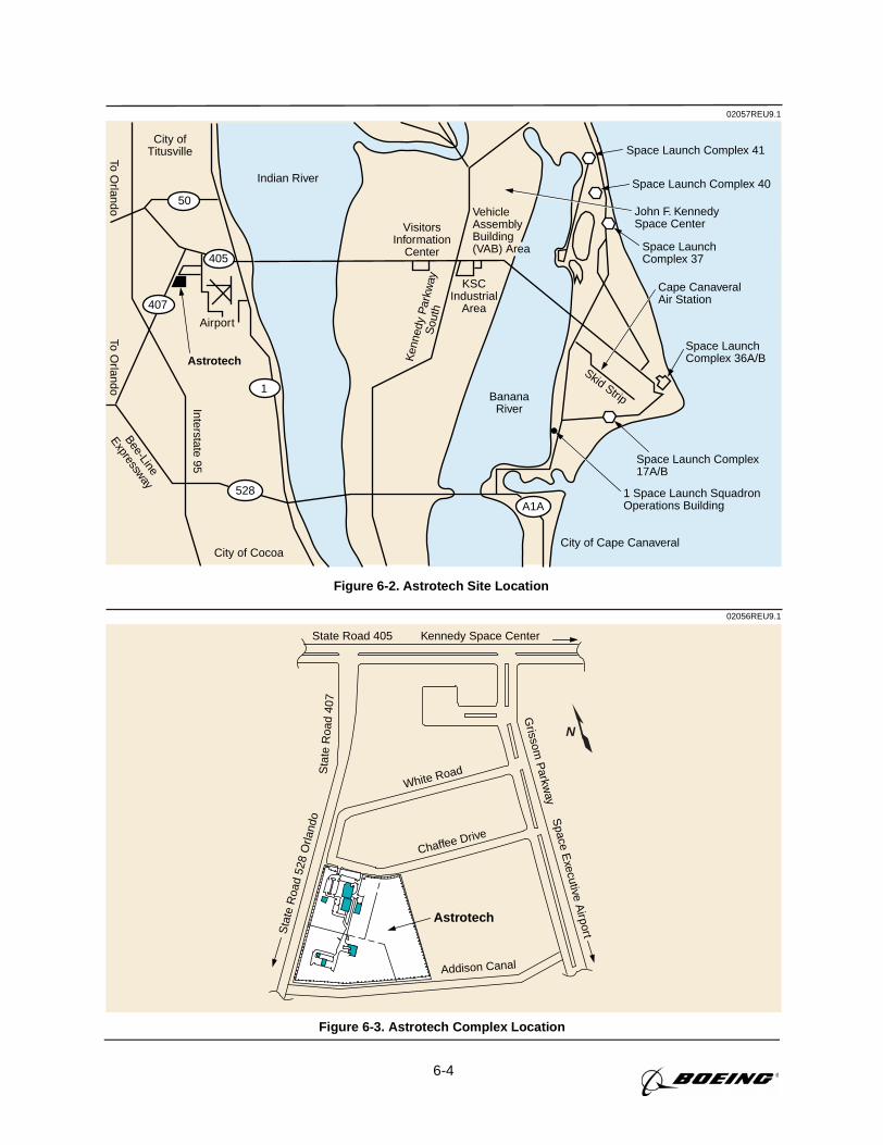
6-4
02057REU9.1
Space Launch Complex17A/B
A1A
City of Cape Canaveral
Skid Strip
VisitorsInformation
Center
KSCIndustrial
Area
VehicleAssemblyBuilding(VAB) Area
Ken
nedy
Par
kway
Sou
th
528
1
407
405
50
Airport
Astrotech
To Orlando
Bee-Line
Expressway
Interstate 95
City of Cocoa
To Orlando
City ofTitusville Space Launch Complex 41
Space Launch Complex 40
Cape CanaveralAir Station
Indian River
John F. KennedySpace Center
Space LaunchComplex 36A/B
Space LaunchComplex 37
1 Space Launch SquadronOperations Building
BananaRiver
Figure 6-2. Astrotech Site Location
N
02056REU9.1
State Road 405 Kennedy Space Center
White Road
Chaffee Drive
Sta
te R
oad
407
Sta
te R
oad
528
Orla
ndo
Addison Canal
Grissom
Parkw
ayS
pace Executive A
irport
Astrotech
Figure 6-3. Astrotech Complex Location
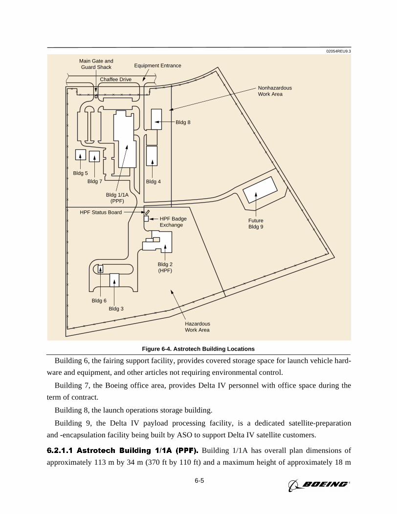
6-5
Building 6, the fairing support facility, provides covered storage space for launch vehicle hard-
ware and equipment, and other articles not requiring environmental control.
Building 7, the Boeing office area, provides Delta IV personnel with office space during the
term of contract.
Building 8, the launch operations storage building.
Building 9, the Delta IV payload processing facility, is a dedicated satellite-preparation
and -encapsulation facility being built by ASO to support Delta IV satellite customers.
6.2.1.1 Astrotech Building 1/1A (PPF). Building 1/1A has overall plan dimensions of
approximately 113 m by 34 m (370 ft by 110 ft) and a maximum height of approximately 18 m
02054REU9.3
NonhazardousWork Area
HazardousWork Area
Bldg 6
Bldg 3
Bldg 2(HPF)
Bldg 4
HPF BadgeExchange
HPF Status Board
FutureBldg 9
Bldg 8
Chaffee Drive
Main Gate andGuard Shack Equipment Entrance
Bldg 1/1A(PPF)
Bldg 7
Bldg 5
Figure 6-4. Astrotech Building Locations
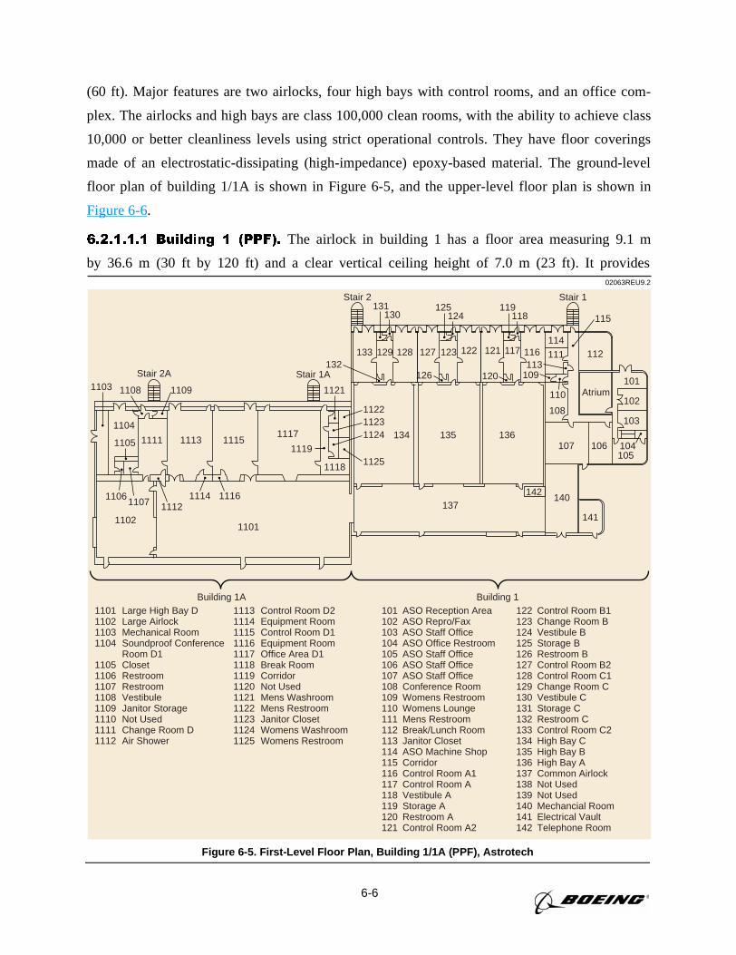
6-6
(60 ft). Major features are two airlocks, four high bays with control rooms, and an office com-
plex. The airlocks and high bays are class 100,000 clean rooms, with the ability to achieve class
10,000 or better cleanliness levels using strict operational controls. They have floor coverings
made of an electrostatic-dissipating (high-impedance) epoxy-based material. The ground-level
floor plan of building 1/1A is shown in Figure 6-5, and the upper-level floor plan is shown in
Figure 6-6.
6.2.1.1.1 Building 1 (PPF). The airlock in building 1 has a floor area measuring 9.1 m
by 36.6 m (30 ft by 120 ft) and a clear vertical ceiling height of 7.0 m (23 ft). It provides02063REU9.2
104
11091108
1122
1125
1121
11231124
1119
131130
132120126
125124
110 Atrium
1118
133 129 128 127
119118
123 116 112
108
109113
101
102
103
105106107
137
13613513411151113
1103
1104
1105
11021101
11071106
Stair 2
Stair 2A
11141112
1116
Stair 1A
Building 1A Building 1
Stair 1
114
115
111
142
1101 Large High Bay D1102 Large Airlock1103 Mechanical Room1104 Soundproof Conference
Room D11105 Closet1106 Restroom1107 Restroom1108 Vestibule1109 Janitor Storage1110 Not Used1111 Change Room D1112 Air Shower
1113 Control Room D21114 Equipment Room1115 Control Room D11116 Equipment Room1117 Office Area D11118 Break Room1119 Corridor1120 Not Used1121 Mens Washroom1122 Mens Restroom1123 Janitor Closet1124 Womens Washroom1125 Womens Restroom
101 ASO Reception Area102 ASO Repro/Fax103 ASO Staff Office104 ASO Office Restroom105 ASO Staff Office106 ASO Staff Office107 ASO Staff Office108 Conference Room109 Womens Restroom110 Womens Lounge111 Mens Restroom112 Break/Lunch Room113 Janitor Closet114 ASO Machine Shop115 Corridor116 Control Room A1117 Control Room A118 Vestibule A119 Storage A120 Restroom A121 Control Room A2
122 Control Room B1123 Change Room B124 Vestibule B125 Storage B126 Restroom B127 Control Room B2128 Control Room C1129 Change Room C130 Vestibule C131 Storage C132 Restroom C133 Control Room C2134 High Bay C135 High Bay B136 High Bay A137 Common Airlock138 Not Used139 Not Used140 Mechancial Room141 Electrical Vault142 Telephone Room
140
141
121
11171111
117122
Figure 6-5. First-Level Floor Plan, Building 1/1A (PPF), Astrotech
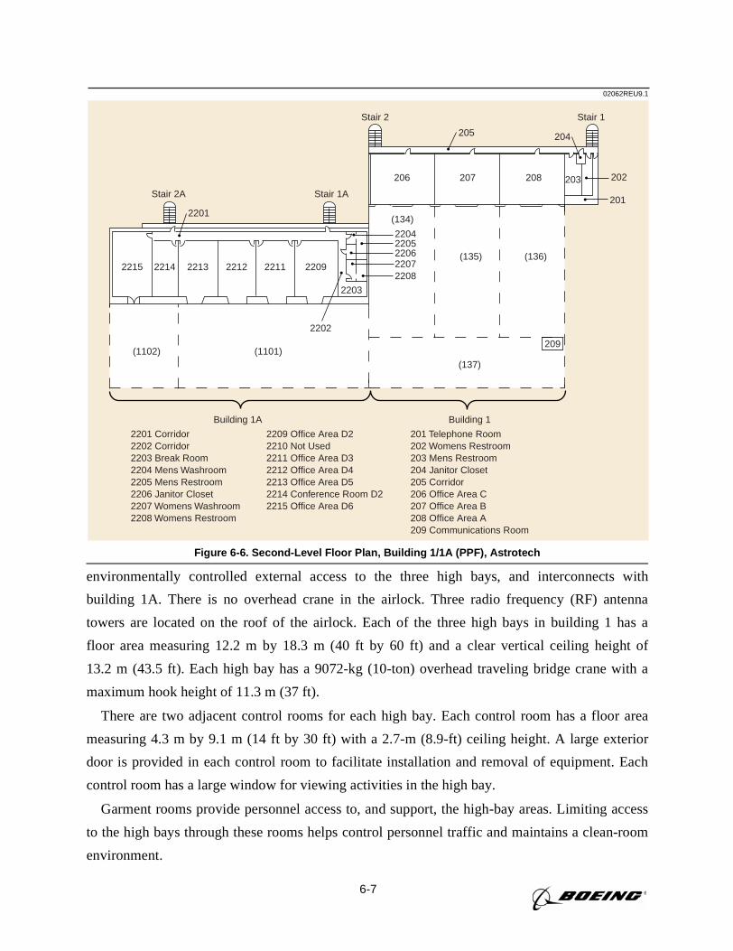
6-7
environmentally controlled external access to the three high bays, and interconnects with
building 1A. There is no overhead crane in the airlock. Three radio frequency (RF) antenna
towers are located on the roof of the airlock. Each of the three high bays in building 1 has a
floor area measuring 12.2 m by 18.3 m (40 ft by 60 ft) and a clear vertical ceiling height of
13.2 m (43.5 ft). Each high bay has a 9072-kg (10-ton) overhead traveling bridge crane with a
maximum hook height of 11.3 m (37 ft).
There are two adjacent control rooms for each high bay. Each control room has a floor area
measuring 4.3 m by 9.1 m (14 ft by 30 ft) with a 2.7-m (8.9-ft) ceiling height. A large exterior
door is provided in each control room to facilitate installation and removal of equipment. Each
control room has a large window for viewing activities in the high bay.
Garment rooms provide personnel access to, and support, the high-bay areas. Limiting access
to the high bays through these rooms helps control personnel traffic and maintains a clean-room
environment.
02062REU9.1
Building 1A Building 1
Stair 2 Stair 1
206 207 208 203
(137)
(136)(135)
(134)
2205
2203
204
Stair 1A
2206
22082211
Stair 2A
221222132214
2201
2215
(1102) (1101)
201
202
205
209
2209 2207
2204
2202
2201 Corridor2202 Corridor2203 Break Room2204 Mens Washroom2205 Mens Restroom2206 Janitor Closet2207 Womens Washroom2208 Womens Restroom
2209 Office Area D22210 Not Used2211 Office Area D32212 Office Area D42213 Office Area D52214 Conference Room D22215 Office Area D6
201 Telephone Room202 Womens Restroom203 Mens Restroom204 Janitor Closet205 Corridor206 Office Area C207 Office Area B208 Office Area A209 Communications Room
Figure 6-6. Second-Level Floor Plan, Building 1/1A (PPF), Astrotech
6-8
Office accommodations for spacecraft project personnel are provided on the upper floor of
building 1 (Figure 6-6). This space is conveniently located near the spacecraft processing area and
contains windows for viewing activities in the high bay.
The remaining areas of building 1 contain the Astrotech offices and shared support areas includ-
ing break room, supply/photocopy room, restroom facilities, and a 24-person conference room.
6.2.1.1.2 Building 1A. In addition to providing access through the building 1 airlock, building
1A contains a separate airlock that is an extension of the high bay and provides environmentally
controlled external access. The airlock has a floor area measuring 12.2 m by 15.5 m (40 ft by 51 ft)
and a clear vertical ceiling height of 18.3 m (60 ft). The airlock is a class 100,000 clean room.
External access for payloads and equipment is provided through a large exterior door.
The exterior wall of the airlock adjacent to the exterior overhead door contains a 4.3-m by
4.3-m (14-ft by 14-ft) RF-transparent window that looks out onto a far-field antenna range that
has a 30.5-m (100-ft)-high target tower located approximately 91.4 m (300 ft) downrange. The
center of the window is 5.8 m (19 ft) above the floor.
The high bay has a floor area measuring 15.5 m by 38.1 m (51 ft by 125 ft) and a clear vertical
ceiling height of 18.3 m (60 ft). The high bay and airlock share a common 27 215-kg (30-ton)
overhead traveling bridge crane with a maximum hook height of 15.2 m (50 ft). Personnel nor-
mally enter the high bay through the garment change room to maintain clean-room standards. The
high bay is class 100,000.
Adjacent to the high bay are two control rooms. Each has a floor area measuring 9.1 m by
10.7 m (30 ft by 35 ft) with a 2.8-m (9.3-ft) ceiling height. Each control room has a large interior
door to permit the direct transfer of equipment between the high bay and the control room; a
large exterior door to facilitate installation and removal of equipment; and a large window for
viewing activities in the high bay.
A garment room provides access for personnel and supports the high bay. Limiting access to
the high bay through this room helps control personnel traffic and maintains a clean-room envi-
ronment. Office accommodations for spacecraft project personnel are provided on the ground
floor and upper floor of building 1A. This space is conveniently located near the spacecraft pro-
cessing area and contains windows for viewing activities in the high bay.
The remaining areas of building 1A contain shared support areas, including break rooms,
restroom facilities, and two 24-person conference rooms (one of which is a secured conference
room designed for the discussion and handling of classified material).
6.2.1.2 Astrotech Building 2 (HPF). Building 2 has overall plan dimensions of 36.6 m by
36.6 m (120 ft by 120 ft) and a height of 14.0 m (46 ft). Major features are two airlocks, three
high bays, and two control rooms. The airlocks and high bays have floor coverings made of
6-9
electrostatic-dissipating (high-impedance) epoxy-based material. They are class 100,000 clean
rooms, with the ability to achieve class 10,000 or better cleanliness levels using strict operational
controls. The ground-level floor plan of building 2 is shown inFigure 6-7.
The south airlock provides environmentally controlled access to building 2 through the south
high bay. The south airlock has a floor area measuring 8.8 m by 11.6 m (29 ft by 38 ft) and a clear
vertical ceiling height of 13.1 m (43 ft). There is no overhead crane in the south airlock.
The north airlock provides environmentally controlled access to building 2 through the north
high bay and, if external building 2 access is restricted to the south airlock, it can be used as a
fourth high bay. The north airlock has a floor area measuring 12.2 m by 15.2 m (40 ft by 50 ft)
and a clear vertical ceiling height of 19.8 m (65 ft). The north airlock has a 27 215-kg (30-ton)
overhead traveling bridge crane with a maximum hook height of 16.8 m (55 ft).
The north and south high bays are designed to support payload solid-propellant motor assem-
bly and liquid monopropellant and bipropellant transfer operations. All liquid-propellant trans-
fer operations take place within a 7.6 m by 7.6 m (25 ft by 25 ft) floor area surrounded by a
trench system. It is sloped so that any major spill of hazardous propellants would drain into the
emergency spill retention system. The north airlock is also configured for propellant loading.
The center high bay contains an 8391-kg (18,500-lb) capacity dynamic balance machine
designed to balance solid rocket motor upper stages and payload. Because the spin balance
table equipment is below the floor level, other uses can be made of this bay. The spin balance
machine control room is separate from the spin room for safety reasons. Television cameras are
used for remote monitoring of spin room activities.
A control room is located next to each processing high bay to facilitate monitoring and control
of hazardous operations. Visual contact with the high bay is through an explosion-proof glass
window in the separating wall. Access to the high bay area from the control room is through the
garment room while spacecraft processing operations are being conducted.
Adjacent to the south high bay, fuel and oxidizer cart storage rooms are provided with access
doors to the high bay and exterior doors for easy equipment access. Garment rooms provide
personnel access to, and support, the high bay areas. Limiting access to the high bays through
these rooms helps control personnel traffic and maintains a clean-room environment.
6.2.1.3 Astrotech Building 3 (Environmental Storage Facility). The dimensions of
building 3 (Figure 6-8) are 15.8 m by 21.6 m (52 ft by 71 ft). The building is divided into six stor-
age bays, each with a clear vertical height of 8.5 m (28 ft). The bays have individual environmen-
tal control but are not clean rooms, which mandates that payloads be stored in suitable containers.
6.2.1.4 Astrotech Building 4 (Warehouse Storage Facility). Building 4 (Figure 6-9)
is 18.9 m by 38.1 m (62 ft by 125 ft), with a maximum roof height of 9.1 m (30 ft). The major
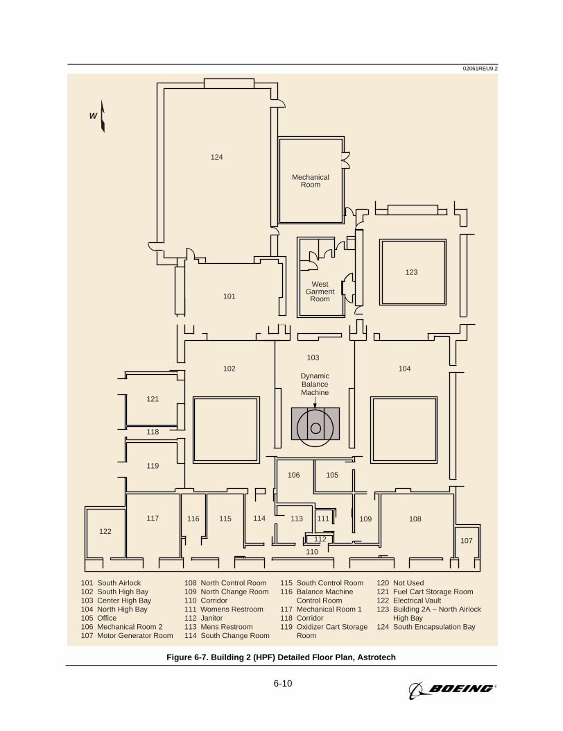
6-10
02061REU9.2
W
115 South Control Room116 Balance Machine Control Room117 Mechanical Room 1118 Corridor119 Oxidizer Cart Storage Room
120 Not Used121 Fuel Cart Storage Room122 Electrical Vault123 Building 2A – North Airlock High Bay124 South Encapsulation Bay
101 South Airlock102 South High Bay103 Center High Bay104 North High Bay105 Office106 Mechanical Room 2107 Motor Generator Room
108 North Control Room109 North Change Room110 Corridor111 Womens Restroom112 Janitor113 Mens Restroom114 South Change Room
123
101
102 104
121
118
119
117 116 115 114 113 111 109 108
122107112
110
106 105
124
MechanicalRoom
WestGarment
Room
DynamicBalanceMachine
103
Figure 6-7. Building 2 (HPF) Detailed Floor Plan, Astrotech
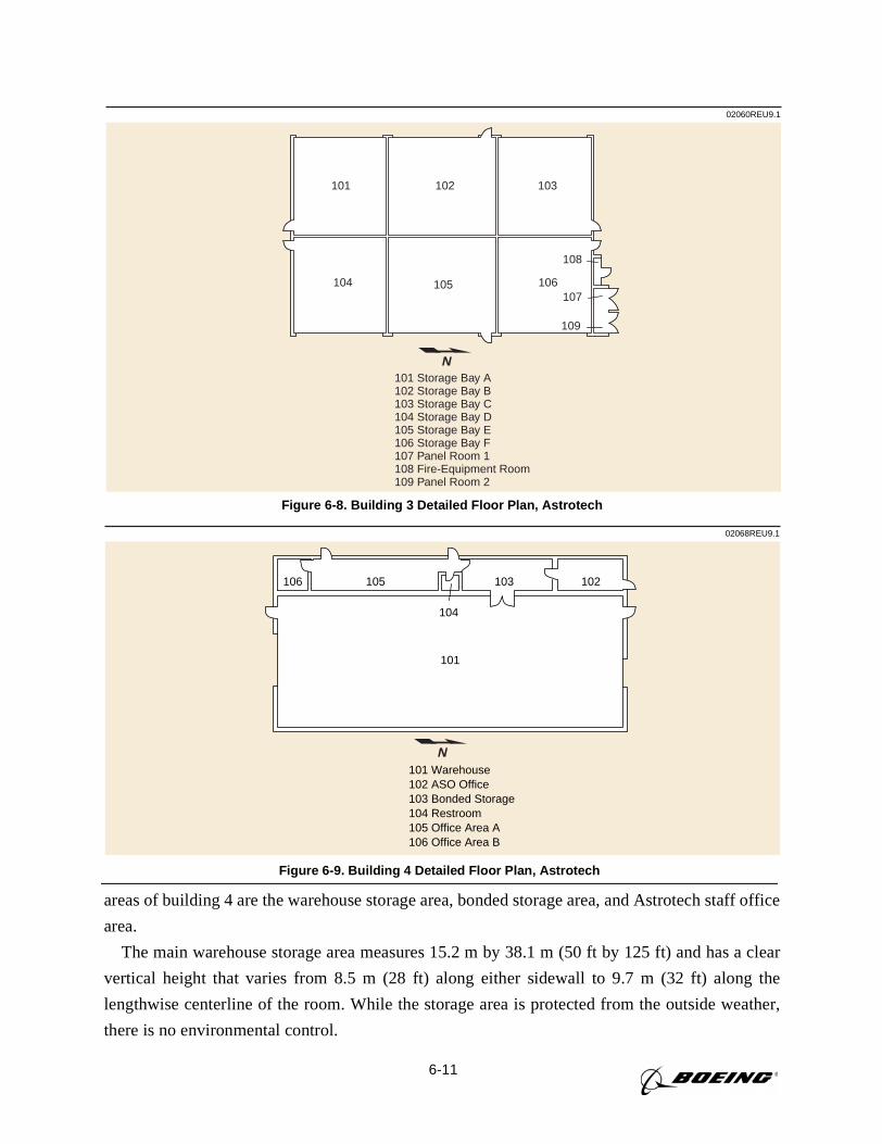
6-11
02060REU9.1
101 102 103
104 105 106
108
107
109
101 Storage Bay A102 Storage Bay B103 Storage Bay C104 Storage Bay D105 Storage Bay E106 Storage Bay F107 Panel Room 1108 Fire-Equipment Room109 Panel Room 2
N
Figure 6-8. Building 3 Detailed Floor Plan, Astrotech
02068REU9.1
104
106 105 103 102
101
101 Warehouse102 ASO Office103 Bonded Storage104 Restroom105 Office Area A106 Office Area B
N
Figure 6-9. Building 4 Detailed Floor Plan, Astrotech
areas of building 4 are the warehouse storage area, bonded storage area, and Astrotech staff office
area.
The main warehouse storage area measures 15.2 m by 38.1 m (50 ft by 125 ft) and has a clear
vertical height that varies from 8.5 m (28 ft) along either sidewall to 9.7 m (32 ft) along the
lengthwise centerline of the room. While the storage area is protected from the outside weather,
there is no environmental control.
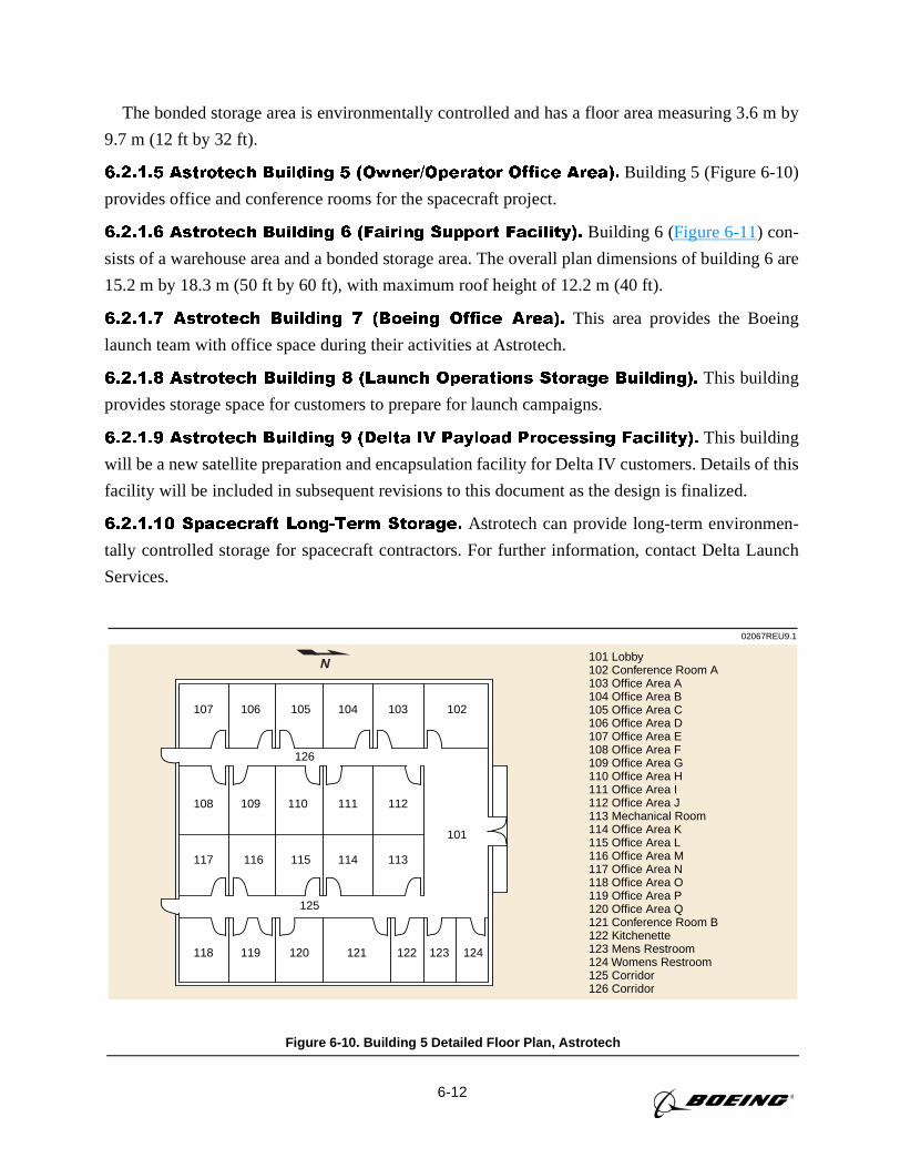
6-12
The bonded storage area is environmentally controlled and has a floor area measuring 3.6 m by
9.7 m (12 ft by 32 ft).
6.2.1.5 Astrotech Building 5 (Owner/Operator Office Area). Building 5 (Figure 6-10)
provides office and conference rooms for the spacecraft project.
6.2.1.6 Astrotech Building 6 (Fairing Support Facility). Building 6 (Figure 6-11) con-
sists of a warehouse area and a bonded storage area. The overall plan dimensions of building 6 are
15.2 m by 18.3 m (50 ft by 60 ft), with maximum roof height of 12.2 m (40 ft).
6.2.1.7 Astrotech Building 7 (Boeing Office Area). This area provides the Boeing
launch team with office space during their activities at Astrotech.
6.2.1.8 Astrotech Building 8 (Launch Operations Storage Building). This building
provides storage space for customers to prepare for launch campaigns.
6.2.1.9 Astrotech Building 9 (Delta IV Payload Processing Facility). This building
will be a new satellite preparation and encapsulation facility for Delta IV customers. Details of this
facility will be included in subsequent revisions to this document as the design is finalized.
6.2.1.10 Spacecraft Long-Term Storage. Astrotech can provide long-term environmen-
tally controlled storage for spacecraft contractors. For further information, contact Delta Launch
Services.
02067REU9.1
101 Lobby102 Conference Room A103 Office Area A104 Office Area B105 Office Area C106 Office Area D107 Office Area E108 Office Area F109 Office Area G110 Office Area H111 Office Area I112 Office Area J113 Mechanical Room114 Office Area K115 Office Area L116 Office Area M117 Office Area N118 Office Area O119 Office Area P120 Office Area Q121 Conference Room B122 Kitchenette123 Mens Restroom124 Womens Restroom125 Corridor126 Corridor
107 106 105 104 103 102
108 109 110 111 112
117 116 115 114 113
118 119 120 121 122 123 124
101
126
125
N
Figure 6-10. Building 5 Detailed Floor Plan, Astrotech
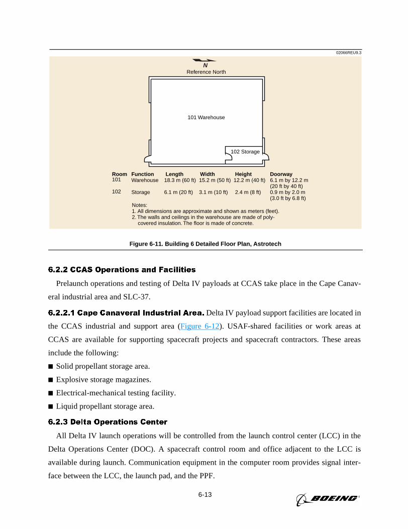
6-13
6.2.2 CCAS Operations and Facilities
Prelaunch operations and testing of Delta IV payloads at CCAS take place in the Cape Canav-
eral industrial area and SLC-37.
6.2.2.1 Cape Canaveral Industrial Area. Delta IV payload support facilities are located in
the CCAS industrial and support area (Figure 6-12). USAF-shared facilities or work areas at
CCAS are available for supporting spacecraft projects and spacecraft contractors. These areas
include the following:
Solid propellant storage area.
Explosive storage magazines.
Electrical-mechanical testing facility.
Liquid propellant storage area.
6.2.3 Delta Operations Center
All Delta IV launch operations will be controlled from the launch control center (LCC) in the
Delta Operations Center (DOC). A spacecraft control room and office adjacent to the LCC is
available during launch. Communication equipment in the computer room provides signal inter-
face between the LCC, the launch pad, and the PPF.
02066REU9.3
101 Warehouse
102 Storage
Notes:1. All dimensions are approximate and shown as meters (feet). 2. The walls and ceilings in the warehouse are made of poly- covered insulation. The floor is made of concrete.
Reference North
Room101
102
FunctionWarehouse
Storage
Length18.3 m (60 ft)
6.1 m (20 ft)
Width 15.2 m (50 ft)
3.1 m (10 ft)
Height 12.2 m (40 ft)
2.4 m (8 ft)
Doorway6.1 m by 12.2 m(20 ft by 40 ft)0.9 m by 2.0 m(3.0 ft by 6.8 ft)
N
Figure 6-11. Building 6 Detailed Floor Plan, Astrotech
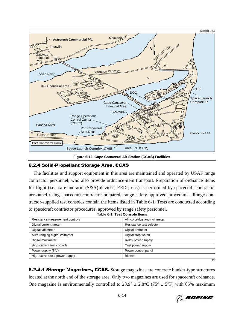
6-14
6.2.4 Solid-Propellant Storage Area, CCAS
The facilities and support equipment in this area are maintained and operated by USAF range
contractor personnel, who also provide ordnance-item transport. Preparation of ordnance items
for flight (i.e., safe-and-arm (S&A) devices, EEDs, etc.) is performed by spacecraft contractor
personnel using spacecraft-contractor-prepared, range-safety-approved procedures. Range-con-
tractor-supplied test consoles contain the items listed in Table 6-1. Tests are conducted according
to spacecraft contractor procedures, approved by range safety personnel.
6.2.4.1 Storage Magazines, CCAS. Storage magazines are concrete bunker-type structures
located at the north end of the storage area. Only two magazines are used for spacecraft ordnance.
One magazine is environmentally controlled to 23.9° ± 2.8°C (75° ± 5°F) with 65% maximum
Table 6-1. Test Console Items
t562
Resistance measurement controls Alinco bridge and null meter
Digital current meter Resistance test selector
Digital voltmeter Digital ammeter
Auto-ranging digital voltmeter Digital stop watch
Digital multimeter Relay power supply
High-current test controls Test power supply
Power supply (5 V) Power control panel
High-current test power supply Blower
02065REU9.4
Titusville
Airfield
Mainland
Area 57E (SRM)
Indian River
Banana River
Kennedy Parkway
Atlantic Ocean
GatewayIndustrialPark
Astrotech Commercial P/L
Port Canaveral Dock
Port CanaveralBoat Dock
Range OperationsControl Center(ROCC)
Cape CanaveralIndustrial Area
KSC Industrial Area
DPF/NPF
HIFDOC
Cocoa Beach
Space LaunchComplex 37
Space Launch Complex 17A/B
N
Figure 6-12. Cape Canaveral Air Station (CCAS) Facilities
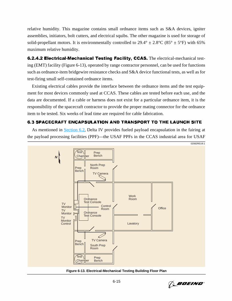
6-15
relative humidity. This magazine contains small ordnance items such as S&A devices, igniter
assemblies, initiators, bolt cutters, and electrical squibs. The other magazine is used for storage of
solid-propellant motors. It is environmentally controlled to 29.4° ± 2.8°C (85° ± 5°F) with 65%
maximum relative humidity.
6.2.4.2 Electrical-Mechanical Testing Facility, CCAS. The electrical-mechanical test-
ing (EMT) facility (Figure 6-13), operated by range contractor personnel, can be used for functions
such as ordnance-item bridgewire resistance checks and S&A device functional tests, as well as for
test-firing small self-contained ordnance items.
Existing electrical cables provide the interface between the ordnance items and the test equip-
ment for most devices commonly used at CCAS. These cables are tested before each use, and the
data are documented. If a cable or harness does not exist for a particular ordnance item, it is the
responsibility of the spacecraft contractor to provide the proper mating connector for the ordnance
item to be tested. Six weeks of lead time are required for cable fabrication.
6.3 SPACECRAFT ENCAPSULATION AND TRANSPORT TO THE LAUNCH SITE
As mentioned inSection 6.2, Delta IV provides fueled payload encapsulation in the fairing at
the payload processing facilities (PPF)—the USAF PPFs in the CCAS industrial area for USAF02082REU9.1
South PrepRoom
TV Camera
Test Chamber
Test Chamber
PrepBench
Ordnance Test Console
Ordnance Test Console
ControlRoom
TVMonitorTVMonitorTVMonitorControl
WorkRoom
Lavatory
Office
TV Camera
North PrepRoomPrep
Bench
PrepBench
PrepBench
N
Figure 6-13. Electrical-Mechanical Testing Building Floor Plan
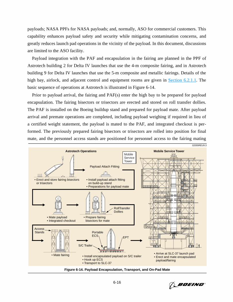
6-16
payloads; NASA PPFs for NASA payloads; and, normally, ASO for commercial customers. This
capability enhances payload safety and security while mitigating contamination concerns, and
greatly reduces launch pad operations in the vicinity of the payload. In this document, discussions
are limited to the ASO facility.
Payload integration with the PAF and encapsulation in the fairing are planned in the PPF of
Astrotech building 2 for Delta IV launches that use the 4-m composite fairing, and in Astrotech
building 9 for Delta IV launches that use the 5-m composite and metallic fairings. Details of the
high bay, airlock, and adjacent control and equipment rooms are given inSection 6.2.1.1. The
basic sequence of operations at Astrotech is illustrated in Figure 6-14.
Prior to payload arrival, the fairing and PAF(s) enter the high bay to be prepared for payload
encapsulation. The fairing bisectors or trisectors are erected and stored on roll transfer dollies.
The PAF is installed on the Boeing buildup stand and prepared for payload mate. After payload
arrival and premate operations are completed, including payload weighing if required in lieu of
a certified weight statement, the payload is mated to the PAF, and integrated checkout is per-
formed. The previously prepared fairing bisectors or trisectors are rolled into position for final
mate, and the personnel access stands are positioned for personnel access to the fairing mating02055REU9.3
Astrotech Operations Mobile Service Tower
• Erect and store fairing bisectors or trisectors
• Install payload attach fitting on build-up stand
• Preparations for payload mate
Payload Attach Fitting
• Arrive at SLC-37 launch pad• Erect and mate encapsulated payload/fairing
• Mate fairing
AccessStands
• Prepare fairing bisectors for mate
RollTransferDollies
• Install encapsulated payload on S/C trailer• Hook up ECS• Transport to SLC-37
PortableECS EPT
S/C Trailer
• Mate payload• Integrated checkout
Mobile Service Tower
Figure 6-14. Payload Encapsulation, Transport, and On-Pad Mate
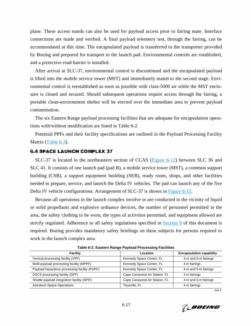
6-17
plane. These access stands can also be used for payload access prior to fairing mate. Interface
connections are made and verified. A final payload telemetry test, through the fairing, can be
accommodated at this time. The encapsulated payload is transferred to the transporter provided
by Boeing and prepared for transport to the launch pad. Environmental controls are established,
and a protective road barrier is installed.
After arrival at SLC-37, environmental control is discontinued and the encapsulated payload
is lifted into the mobile service tower (MST) and immediately mated to the second stage. Envi-
ronmental control is reestablished as soon as possible with class-5000 air while the MST enclo-
sure is closed and secured. Should subsequent operations require access through the fairing, a
portable clean-environment shelter will be erected over the immediate area to prevent payload
contamination.
The six Eastern Range payload processing facilities that are adequate for encapsulation opera-
tions with/without modification are listed in Table 6-2.
Potential PPFs and their facility specifications are outlined in the Payload Processing Facility
Matrix (Table 6-3).
6.4 SPACE LAUNCH COMPLEX 37
SLC-37 is located in the northeastern section of CCAS (Figure 6-12) between SLC 36 and
SLC 41. It consists of one launch pad (pad B), a mobile service tower (MST), a common support
building (CSB), a support equipment building (SEB), ready room, shops, and other facilities
needed to prepare, service, and launch the Delta IV vehicles. The pad can launch any of the five
Delta IV vehicle configurations. Arrangement of SLC-37 is shown inFigure 6-15.
Because all operations in the launch complex involve or are conducted in the vicinity of liquid
or solid propellants and explosive ordnance devices, the number of personnel permitted in the
area, the safety clothing to be worn, the types of activities permitted, and equipment allowed are
strictly regulated. Adherence to all safety regulations specified inSection 9of this document is
required. Boeing provides mandatory safety briefings on these subjects for persons required to
work in the launch complex area.
Table 6-2. Eastern Range Payload Processing FacilitiesFacility Location Encapsulation capability
Vertical processing facility (VPF) Kennedy Space Center, FL 4-m and 5-m fairings
Multi-payload processing facility (MPPF) Kennedy Space Center, FL 4-m fairings
Payload hazardous processing facility (PHPF) Kennedy Space Center, FL 4-m and 5-m fairings
DSCS processing facility (DPF) Cape Canaveral Air Station, FL 4-m fairings
Shuttle payload integration facility (SPIF) Cape Canaveral Air Station, FL 4-m and 5-m fairings
Astrotech Space Operations Titusville, FL 4-m fairings
t564.4
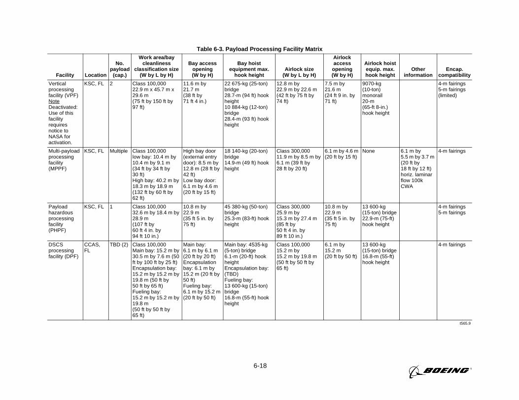
6-18
Table 6-3. Payload Processing Facility Matrix
Facility Location
No. payload
(cap.)
Work area/bay cleanliness
classification size (W by L by H)
Bay access opening(W by H)
Bay hoist equipment max.
hook heightAirlock size
(W by L by H)
Airlock access
opening(W by H)
Airlock hoist equip. max. hook height
Other information
Encap. compatibility
Vertical processing facility (VPF) Note Deactivated: Use of this facility requires notice to NASA for activation.
KSC, FL 2 Class 100,00022.9 m x 45.7 m x 29.6 m(75 ft by 150 ft by 97 ft)
11.6 m by 21.7 m(38 ft by 71 ft 4 in.)
22 675-kg (25-ton) bridge 28.7-m (94 ft) hook height10 884-kg (12-ton) bridge 28.4-m (93 ft) hook height
12.8 m by 22.9 m by 22.6 m (42 ft by 75 ft by 74 ft)
7.5 m by 21.6 m (24 ft 9 in. by 71 ft)
9070-kg (10-ton) monorail 20-m (65-ft 8-in.) hook height
4-m fairings5-m fairings (limited)
Multi-payload processing facility (MPPF)
KSC, FL Multiple Class 100,000low bay: 10.4 m by 10.4 m by 9.1 m (34 ft by 34 ft by 30 ft)High bay: 40.2 m by 18.3 m by 18.9 m (132 ft by 60 ft by 62 ft)
High bay door (external entry door): 8.5 m by 12.8 m (28 ft by 42 ft)Low bay door: 6.1 m by 4.6 m (20 ft by 15 ft)
18 140-kg (20-ton) bridge 14.9-m (49 ft) hook height
Class 300,00011.9 m by 8.5 m by 6.1 m (39 ft by 28 ft by 20 ft)
6.1 m by 4.6 m (20 ft by 15 ft)
None 6.1 m by 5.5 m by 3.7 m (20 ft by 18 ft by 12 ft) horiz. laminar flow 100k CWA
4-m fairings
Payload hazardous processing facility (PHPF)
KSC, FL 1 Class 100,000 32.6 m by 18.4 m by 28.9 m(107 ft by 60 ft 4 in. by 94 ft 10 in.)
10.8 m by 22.9 m (35 ft 5 in. by 75 ft)
45 380-kg (50-ton) bridge25.3-m (83-ft) hook height
Class 300,00025.9 m by 15.3 m by 27.4 m (85 ft by 50 ft 4 in. by 89 ft 10 in.)
10.8 m by 22.9 m (35 ft 5 in. by 75 ft)
13 600-kg (15-ton) bridge22.9-m (75-ft) hook height
4-m fairings5-m fairings
DSCS processing facility (DPF)
CCAS, FL
TBD (2) Class 100,000 Main bay: 15.2 m by 30.5 m by 7.6 m (50 ft by 100 ft by 25 ft)Encapsulation bay: 15.2 m by 15.2 m by 19.8 m (50 ft by 50 ft by 65 ft)Fueling bay: 15.2 m by 15.2 m by 19.8 m (50 ft by 50 ft by 65 ft)
Main bay: 6.1 m by 6.1 m (20 ft by 20 ft)Encapsulation bay: 6.1 m by 15.2 m (20 ft by 50 ft) Fueling bay: 6.1 m by 15.2 m (20 ft by 50 ft)
Main bay: 4535-kg (5-ton) bridge6.1-m (20-ft) hook heightEncapsulation bay: (TBD)Fueling bay: 13 600-kg (15-ton) bridge16.8-m (55-ft) hook height
Class 100,000 15.2 m by 15.2 m by 19.8 m (50 ft by 50 ft by 65 ft)
6.1 m by 15.2 m (20 ft by 50 ft)
13 600-kg (15-ton) bridge16.8-m (55-ft) hook height
4-m fairings
t565.9
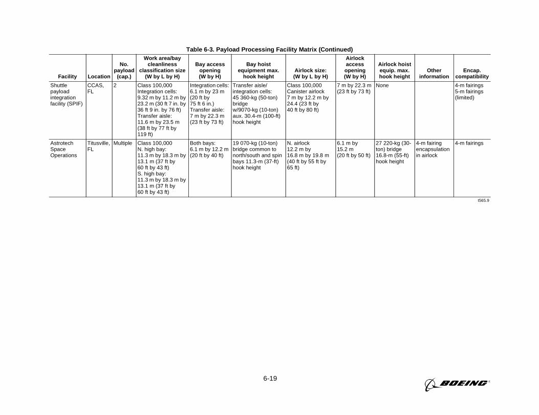
6-19
Table 6-3. Payload Processing Facility Matrix (Continued)
Facility Location
No.payload
(cap.)
Work area/baycleanliness
classification size(W by L by H)
Bay accessopening(W by H)
Bay hoistequipment max.
hook heightAirlock size:
(W by L by H)
Airlockaccess
opening(W by H)
Airlock hoistequip. max.hook height
Otherinformation
Encap.compatibility
Shuttlepayloadintegrationfacility (SPIF)
CCAS,FL
2 Class 100,000Integration cells:9.32 m by 11.2 m by23.2 m (30 ft 7 in. by36 ft 9 in. by 76 ft)Transfer aisle:11.6 m by 23.5 m(38 ft by 77 ft by119 ft)
Integration cells:6.1 m by 23 m(20 ft by75 ft 6 in.)Transfer aisle:7 m by 22.3 m(23 ft by 73 ft)
Transfer aisle/integration cells:45 360-kg (50-ton)bridgew/9070-kg (10-ton)aux. 30.4-m (100-ft)hook height
Class 100,000Canister airlock7 m by 12.2 m by24.4 (23 ft by40 ft by 80 ft)
7 m by 22.3 m(23 ft by 73 ft)
None 4-m fairings5-m fairings(limited)
AstrotechSpaceOperations
Titusville,FL
Multiple Class 100,000N. high bay:11.3 m by 18.3 m by13.1 m (37 ft by60 ft by 43 ft)S. high bay:11.3 m by 18.3 m by13.1 m (37 ft by60 ft by 43 ft)
Both bays:6.1 m by 12.2 m(20 ft by 40 ft)
19 070-kg (10-ton)bridge common tonorth/south and spinbays 11.3-m (37-ft)hook height
N. airlock12.2 m by16.8 m by 19.8 m(40 ft by 55 ft by65 ft)
6.1 m by15.2 m(20 ft by 50 ft)
27 220-kg (30-ton) bridge16.8-m (55-ft)hook height
4-m fairingencapsulationin airlock
4-m fairings
t565.9
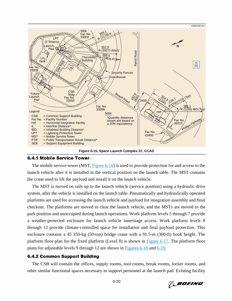
6-20
6.4.1 Mobile Service Tower
The mobile service tower (MST,Figure 6-16) is used to provide protection for and access to the
launch vehicle after it is installed in the vertical position on the launch table. The MST contains
the crane used to lift the payload and install it on the launch vehicle.
The MST is moved on rails up to the launch vehicle (service position) using a hydraulic drive
system, after the vehicle is installed on the launch table. Pneumatically and hydraulically operated
platforms are used for accessing the launch vehicle and payload for integration assembly and final
checkout. The platforms are moved to clear the launch vehicle, and the MSTs are moved to the
park position and unoccupied during launch operations. Work platform levels 5 through 7 provide
a weather-protected enclosure for launch vehicle innerstage access. Work platform levels 8
through 12 provide climate-controlled space for installation and final payload protection. This
enclosure contains a 45 350-kg (50-ton) bridge crane with a 91.5-m (300-ft) hook height. The
platform floor plan for the fixed platform (Level 8) is shown inFigure 6-17. The platform floor
plans for adjustable levels 9 through 12 are shown inFigures 6-18and6-19.
6.4.2 Common Support Building
The CSB will contain the offices, supply rooms, tool rooms, break rooms, locker rooms, and
other similar functional spaces necessary to support personnel at the launch pad. Existing facility
02081REU9.1
N
CSBFac No.HIFILIBDLPTMSTPTRSEB
Legend
= Common Support Building= Facility Number= Horizontal Integration Facility= Interline Distance*= Inhabited Building Distance*= Lightning Protection Tower= Mobile Service Tower= Public Transportation Route Distance*= Support Equipment Building
m(ft)
Gas
Are
a
Fac No.33008
Fac No.43400
Fac No.38315
*Quantity distancesshown are based ona 20% equivalency
Note:
LaunchPad
LH2Tank
LPT(2 Towers)
FutureLaunch
Pad
CSBBldg
Fac No.33000
TheodoliteBuilding
SEBFac No.33002
R (1178) IL359.1
Phillips Parkway
3400
HIF
Beach Road
Pat
rol R
oad
Fac No.33006
R (1827) (Med)557.0
Security FencesGuardhouse
598.5R (1963) PTR
(600
)
182.
9
(1000)
304.9
R (750) PTR (Typ)
228.7
R (1250) IBD (Typ)381.1
Figure 6-15. Space Launch Complex 37, CCAS
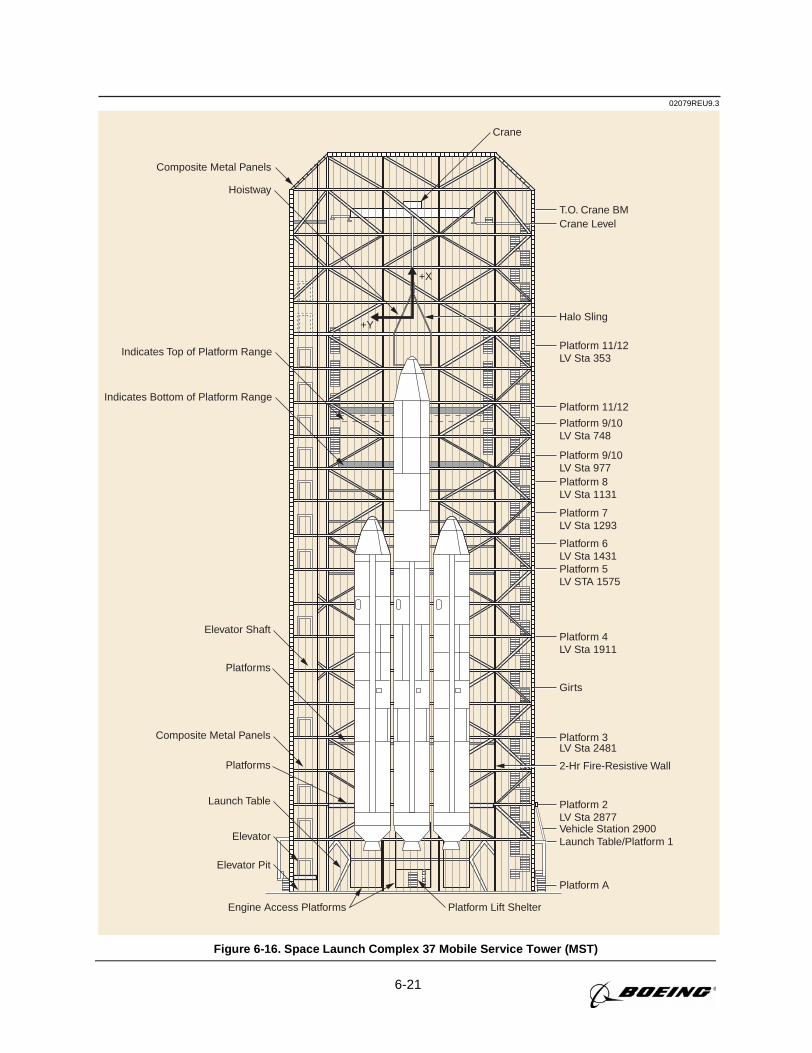
6-21
02079REU9.3
Composite Metal Panels
Hoistway
Halo Sling
Elevator
Elevator Pit
Engine Access Platforms Platform Lift Shelter
Launch Table
Elevator Shaft
Platform A
Launch Table/Platform 1Vehicle Station 2900
Platform 2LV Sta 2877
Platform 3LV Sta 2481
Girts
Platform 5LV STA 1575
Platform 6LV Sta 1431
Platform 7LV Sta 1293
Platform 8LV Sta 1131
Platform 9/10LV Sta 977
Platform 11/12
Indicates Top of Platform Range
Indicates Bottom of Platform Range
Platform 11/12LV Sta 353
Crane LevelT.O. Crane BM
Crane
+X
+Y
Platform 9/10LV Sta 748
Platform 4LV Sta 1911
2-Hr Fire-Resistive Wall
Platforms
Composite Metal Panels
Platforms
Figure 6-16. Space Launch Complex 37 Mobile Service Tower (MST)
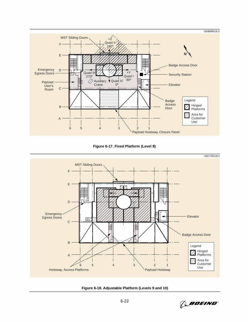
6-22
02080REU9.3
6 5 4 3 2 1
F
E
D
C
B
A
Security Station
ElevatorPayload
User'sRoom
AuxiliaryCrane
HingedPlatforms
Area for Customer Use
Legend
Quad III270º
+ZQuad II
180º
Quad IV0º
MST Sliding Doors
+YQuad I
90º
Payload Hoistway, Closure Panel
N
Badge Access Door
BadgeAccessDoor
EmergencyEgress Doors
Figure 6-17. Fixed Platform (Level 8)
02077REU9.2
HingedPlatforms
Area for Customer Use
Legend
6 5 4 3 2 1
F
E
D
C
B
A
MST Sliding Doors
Payload Hoistway
Elevator
Hoistway, Access Platforms
Badge Access Door
EmergencyEgress Doors
Figure 6-18. Adjustable Platform (Levels 9 and 10)
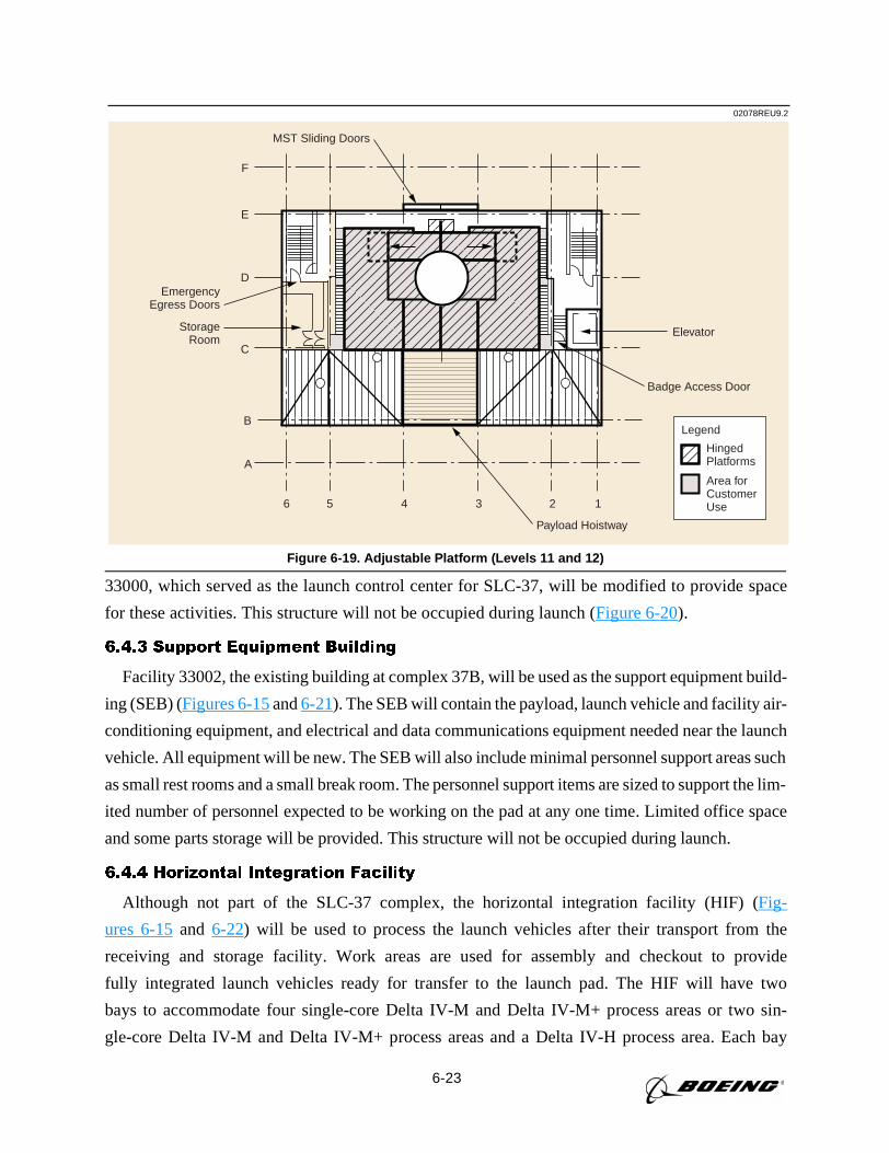
6-23
02078REU9.2
HingedPlatforms
Area for Customer Use
Legend
Badge Access Door
EmergencyEgress Doors
6 5 4 3 2 1
F
E
D
C
B
A
MST Sliding Doors
Payload Hoistway
ElevatorStorageRoom
Figure 6-19. Adjustable Platform (Levels 11 and 12)
33000, which served as the launch control center for SLC-37, will be modified to provide space
for these activities. This structure will not be occupied during launch (Figure 6-20).
6.4.3 Support Equipment Building
Facility 33002, the existing building at complex 37B, will be used as the support equipment build-
ing (SEB) (Figures 6-15and6-21). The SEB will contain the payload, launch vehicle and facility air-
conditioning equipment, and electrical and data communications equipment needed near the launch
vehicle. All equipment will be new. The SEB will also include minimal personnel support areas such
as small rest rooms and a small break room. The personnel support items are sized to support the lim-
ited number of personnel expected to be working on the pad at any one time. Limited office space
and some parts storage will be provided. This structure will not be occupied during launch.
6.4.4 Horizontal Integration Facility
Although not part of the SLC-37 complex, the horizontal integration facility (HIF) (Fig-
ures 6-15and 6-22) will be used to process the launch vehicles after their transport from the
receiving and storage facility. Work areas are used for assembly and checkout to provide
fully integrated launch vehicles ready for transfer to the launch pad. The HIF will have two
bays to accommodate four single-core Delta IV-M and Delta IV-M+ process areas or two sin-
gle-core Delta IV-M and Delta IV-M+ process areas and a Delta IV-H process area. Each bay
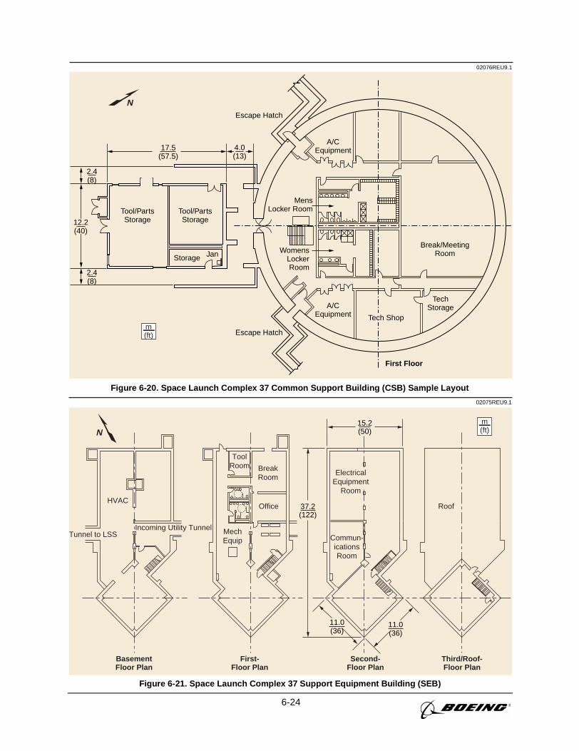
6-24
02076REU9.1
Tool/PartsStorage
Tool/PartsStorage
Escape Hatch
Escape Hatch
A/CEquipment
A/CEquipment
TechStorage
First Floor
Break/MeetingRoom
MensLocker Room
WomensLockerRoom
Storage Jan
m(ft)
(57.5)17.5
(13)4.0
(40)12.2
(8)2.4
(8)2.4
N
Tech Shop
Figure 6-20. Space Launch Complex 37 Common Support Building (CSB) Sample Layout
02075REU9.1
Third/Roof-Floor Plan
Roof
m(ft)
Tunnel to LSS
HVAC
Incoming Utility Tunnel
BasementFloor Plan
First-Floor Plan
Second-Floor Plan
ElectricalEquipment
Room
Commun-icationsRoom
BreakRoom
Office
MechEquip
ToolRoom
(122)37.2
(36)11.0
(36)11.0
(50)15.2
N
Figure 6-21. Space Launch Complex 37 Support Equipment Building (SEB)
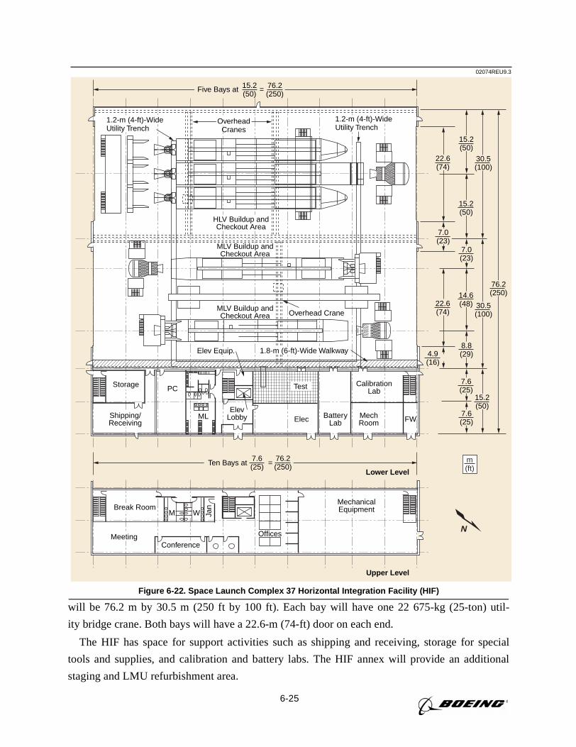
6-25
will be 76.2 m by 30.5 m (250 ft by 100 ft). Each bay will have one 22 675-kg (25-ton) util-
ity bridge crane. Both bays will have a 22.6-m (74-ft) door on each end.
The HIF has space for support activities such as shipping and receiving, storage for special
tools and supplies, and calibration and battery labs. The HIF annex will provide an additional
staging and LMU refurbishment area.
02074REU9.3
Overhead Crane
Elev Equip.
Lower Level
Upper Level
Storage PC
ML FWElev
Lobby Elec
OfficesMeeting
M W Jan
BatteryLab
MechRoom
CalibrationLab
Test
Shipping/Receiving
MechanicalEquipmentBreak Room
MLV Buildup andCheckout Area
MLV Buildup andCheckout Area
HLV Buildup andCheckout Area
OverheadCranes
Conference
m(ft)
Five Bays at = (50)15.2
(250)76.2
1.8-m (6-ft)-Wide Walkway
1.2-m (4-ft)-WideUtility Trench
1.2-m (4-ft)-WideUtility Trench
Ten Bays at = 7.6(25)
76.2(250)
7.6(25)
15.2(50)
7.6(25)
8.8(29)4.9
(16)
76.2(250)
30.5(100)
14.6(48)22.6
(74)
7.0(23)
7.0(23)
15.2(50)
30.5(100)
15.2(50)
22.6(74)
N
Figure 6-22. Space Launch Complex 37 Horizontal Integration Facility (HIF)
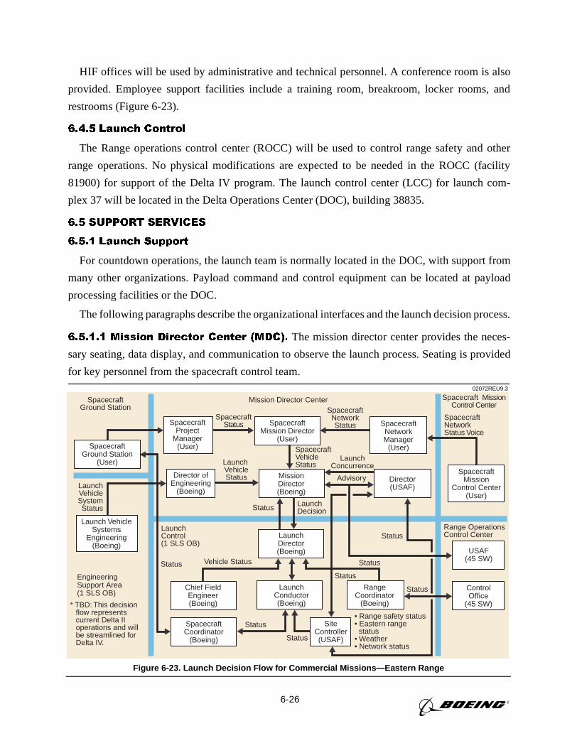
6-26
HIF offices will be used by administrative and technical personnel. A conference room is also
provided. Employee support facilities include a training room, breakroom, locker rooms, and
restrooms (Figure 6-23).
6.4.5 Launch Control
The Range operations control center (ROCC) will be used to control range safety and other
range operations. No physical modifications are expected to be needed in the ROCC (facility
81900) for support of the Delta IV program. The launch control center (LCC) for launch com-
plex 37 will be located in the Delta Operations Center (DOC), building 38835.
6.5 SUPPORT SERVICES
6.5.1 Launch Support
For countdown operations, the launch team is normally located in the DOC, with support from
many other organizations. Payload command and control equipment can be located at payload
processing facilities or the DOC.
The following paragraphs describe the organizational interfaces and the launch decision process.
6.5.1.1 Mission Director Center (MDC). The mission director center provides the neces-
sary seating, data display, and communication to observe the launch process. Seating is provided
for key personnel from the spacecraft control team.
Launch VehicleStatus
SpacecraftMission Director
(User)
SpacecraftStatusSpacecraft
ProjectManager
(User)
MissionDirector(Boeing)
SpacecraftVehicleStatus
Director ofEngineering
(Boeing)
LaunchConcurrence
LaunchDecisionStatus
Vehicle Status
LaunchConductor(Boeing)
SiteController(USAF)
LaunchDirector(Boeing)
• Range safety status• Eastern range status• Weather• Network status
Range OperationsControl Center
Status
EngineeringSupport Area(1 SLS OB)
SpacecraftGround Station
Mission Director Center
LaunchVehicleSystemStatus
SpacecraftNetworkManager
(User)
Spacecraft Mission Control Center
SpacecraftNetworkStatus Voice
SpacecraftNetwork Status
Advisory
USAF(45 SW)
ControlOffice
(45 SW)
SpacecraftCoordinator
(Boeing)
Status
LaunchControl(1 SLS OB)
Status
Status
Status
Status
Status
Launch VehicleSystems
Engineering(Boeing)
Spacecraft Mission
Control Center(User)
SpacecraftGround Station
(User)
RangeCoordinator
(Boeing)
Chief FieldEngineer(Boeing)* TBD: This decision
flow representscurrent Delta IIoperations and willbe streamlined forDelta IV.
Director(USAF)
02072REU9.3
Figure 6-23. Launch Decision Flow for Commercial Missions—Eastern Range
6-27
6.5.1.2 Launch Decision Process. The launch decision process is conducted by appro-
priate management personnel representing the payload, the launch vehicle, and the range.
Figure 6-23shows the typical communication flow required to make the launch decision for
Delta II/III. The Delta IV process is currently evolving but will generally follow the same
decision paths as Delta II/III.
6.5.2 Weather Constraints
6.5.2.1 Ground-Wind Constraints. The Delta IV launch vehicles will be enclosed in the
MST until approximately launch- (L-) 7 hr. The tower protects the launch vehicle from ground
winds (measured using anemometers at several levels of the tower).
6.5.2.2 Winds-Aloft Constraints. Measurements of winds aloft are taken at the launch pad.
On launch day, Delta IV launch vehicle controls and load constraints for winds aloft are evaluated
by conducting a trajectory analysis using the measured wind. A curve fit to the wind data provides
load relief in the trajectory analysis. The curve fit and other load-relief parameters are used to
reset the mission constants just prior to launch.
6.5.2.3 Weather Constraints. Weather constraints are imposed by range safety to assure
safe passage of the Delta IV launch vehicle through the atmosphere. The following condensed
set of constraints is evaluated just prior to liftoff. (The complete set of constraints is contained
in Appendix B.)
A. The launch will not take place if the normal flight path will carry the launch vehicle:
1. Within 18.5 km (10 nmi) of a cumulo-nimbus (thunderstorm) cloud, whether convec-
tive or in layers, where precipitation (or virga) is observed.
2. Through any cloud, whether convective or in layers, where precipitation or virga is
observed.
3. Through any frontal or squall-line clouds which extend above 3048 m (10,000 ft).
4. Through cloud layers or through cumulus clouds where the freeze level is in the
clouds.
5. Through any cloud if a ±1 kV/m or greater level electric field contour passes within
9.3 km (5 nmi) of the launch site at any time within 15 min prior to liftoff.
6. Through previously electrified clouds not monitored by an electrical field mill network
if the dissipating state was short-lived (less than 15 min after observed electrical activity).
B. The launch will not take place if there is precipitation over the launch site or along the
flight path.
C. A weather observation aircraft is mandatory to augment meteorological capabilities for
real-time evaluation of local conditions unless a cloud-free line of sight exists to the launch vehi-
cle flight path. Rawinsonde will not be used to determine cloud buildup.
6-28
D. Even though the above criteria are observed or forecast to be satisfied at the predicted
launch time, the launch director may elect to delay the launch based on the instability of atmo-
spheric conditions.
6.5.2.4 Lightning Activity. The following are procedures for test status during lightning
activity:
A. Evacuation of the MST is accomplished at the direction of the launch conductor (Refer-
ence: Delta Launch Complex Safety Plan).
B. Instrumentation may be operated during an electrical storm.
C. If other electrical systems are powered when an electrical storm approaches, these systems
may remain powered.
D. If an electrical storm passes through after vehicle automated interface tests are performed,
all electrical systems are turned on to a quiescent state, and all data sources are evaluated for evi-
dence of damage. This turn-on is done remotely (pad clear) if any Category-A ordnance circuits
are connected for flight. Ordnance circuits are disconnected and safed prior to turn-on with person-
nel exposed to the vehicle.
E. If data from the health monitoring turn-on reveals equipment discrepancies that can be
attributed to the electrical storm, a flight program requalification test must be run subsequent to
the storm and prior to a launch attempt.
6.5.3 Operational Safety
Safety requirements are covered inSection 9of this document. In addition, it is the operating
policy at both CCAS and Astrotech that all personnel will be given safety orientation briefings
prior to entrance to hazardous areas. These briefings will be scheduled by the Boeing spacecraft
coordinator and presented by the appropriate safety personnel.
6.5.4 Security
6.5.4.1 CCAS Security. For access to CCAS, US citizens must provide to Boeing security their
full name with middle initial (if applicable), social security number, company name, company
address, company telephone, and dates of arrival and expected departure by seven days prior to
arrival. Boeing security will arrange for entry authority for commercial missions or individuals
sponsored by Boeing. Access by NASA personnel or NASA-sponsored foreign nationals is coor-
dinated by NASA KSC with the USAF at CCAS. Access by other US government-sponsored for-
eign nationals is coordinated by their sponsor directly with the USAF at CCAS. For non-US
citizens, entry authority information (name, nationality/citizenship, date and place of birth, passport
number and date/place of issue, visa number and date of expiration, and title or job description,
organization, company address, home address) must be furnished to Boeing security two months
prior to the CCAS entry date. Government-sponsored individuals follow NASA or US government
6-29
guidelines, as appropriate. After Boeing security gets entry authority approval, entry to CCAS will
be the same as for US citizens.
For security requirements at facilities other than those listed below, please see the appropriate
facility user guide.
6.5.4.2 Launch Complex Security. SLC-37 physical security is ensured by perimeter fenc-
ing, guards, and access badges. The MST is configured to provide security for Priority-A
resources. Unique badging is required for unescorted entry into the fenced area at SLC-37.
Arrangements must be made through Boeing security at least 30 days prior to need to begin badg-
ing arrangements for personnel requiring such access. Boeing personnel are also available 24 hr a
day to provide escort to others requiring access.
6.5.4.3 Astrotech Security. Physical security at the Astrotech facilities is provided by
chain-link perimeter fencing, door locks, and guards. Details of payload security requirements
will be arranged through the Boeing spacecraft coordinator.
6.5.5 Field-Related Services
Boeing employs certified handlers wearing propellant handler’s ensemble (PHE) suits, equip-
ment drivers, welders, riggers, and explosive ordnance handlers in addition to personnel experi-
enced in most electrical and mechanical assembly skills such as torquing, soldering, crimping,
precision cleaning, and contamination control. Boeing has access to a machine shop, metrology
laboratory, LO2 cleaning facility, proof-load facility, and hydrostatic proof test equipment. Boeing
operational team members are familiar with the payload processing facilities and can offer all
these skills and services to the spacecraft contractor during the launch program.
6.6 DELTA IV PLANS AND SCHEDULES
6.6.1 Mission Plan
At least 12 months prior to each launch campaign, a mission launch operations schedule is
developed that shows major tasks in a weekly timeline format. The plan includes launch vehicle
activities, prelaunch reviews, and spacecraft payload processing facility (PPF) and boost vehicles
horizontal integration facility (HIF) occupancy time.
6.6.2 Integrated Schedules
The schedule of payload activities occurring before integrated activities in the HIF varies from
mission to mission. The extent of payload field testing varies and is determined by the spacecraft
contractor.
Payload/launch vehicle schedules are similar from mission to mission, from the time of payload
weighing until launch.
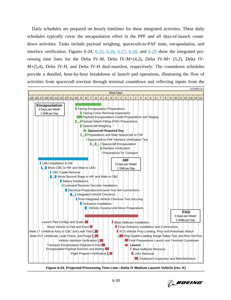
6-30
Daily schedules are prepared on hourly timelines for these integrated activities. These daily
schedules typically cover the encapsulation effort in the PPF and all days-of-launch count-
down activities. Tasks include payload weighing, spacecraft-to-PAF mate, encapsulation, and
interface verification. Figures 6-24,6-25, 6-26, 6-27, 6-28, and 6-29 show the integrated pro-
cessing time lines for the Delta IV-M, Delta IV-M+(4,2), Delta IV-M+ (5,2), Delta IV-
M+(5,4), Delta IV-H, and Delta IV-H dual-manifest, respectively. The countdown schedules
provide a detailed, hour-by-hour breakdown of launch pad operations, illustrating the flow of
activities from spacecraft erection through terminal countdown and reflecting inputs from the
01978REU9.4
Work Days
-12-13-14-15-16-17-18-19 -11 -10 -9 -8 -7 -6 -5 -4 -3 -2 -1 0 1 2 3 4 5 7 8 9 10 11 12 13 14 156
Fairing Encapsulation PreparationsFairing Cover Removal Inspections
Spacecraft-to-PAF Interface Verification Test
Interface Verification
Payload Encapsulation Cradle Preparations and StagingPayload Attach Fitting (PAF) Preparations
Spacecraft Required DayPreparations and Mate Spacecraft to PAF
Spacecraft Encapsulation
Preparations for Transport
Spacecraft Weighing
Encapsulation5 Days per Week/
1 Shift per Day
Move CBC to HIF and Mate to LMU
CBC Cradle RemovalMove Second Stage to HIF and Mate to CBC
Battery Installations
LMU Installation in HIF
Ordnance InstallationVehicle Closeout and Move Preparations
Command Receiver Decoder Installation
Electrical Preparations/Ground Test Set ConnectionsIntegrated Vehicle Checkout
Post-Integrated Vehicle Checkout Test Securing
HIF5 Days per Week/
1 Shift per Day
Launch Pad Configs and Quals
Move Vehicle to Pad and Erect Final Ordnance Installation and Connections
Mate LT Umbilical Assy to CBC and Leak Test
Blast Deflector Installation
ACS Vehicle Prop Loading, Prop and Pneumatic Watch
Mate FUT Umbilicals, Leak Check, and Purge Prop System Loading, Range Safety Test, and Rmv Ord Pins
Vehicle Interface Verification Final Preparations Launch and Terminal Countdown
Transport Encapsulated Payload to Pad LaunchEncapsulated Payload Erection and Mating
Flight Program VerificationBlast Deflector Removal
LMU Retrieval
Postlaunch Inspection and Refurbishment
PAD5 Days per Week/2 Shifts per Day
Figure 6-24. Projected Processing Time Line—Delta IV Medium Launch Vehicle (rev. K)
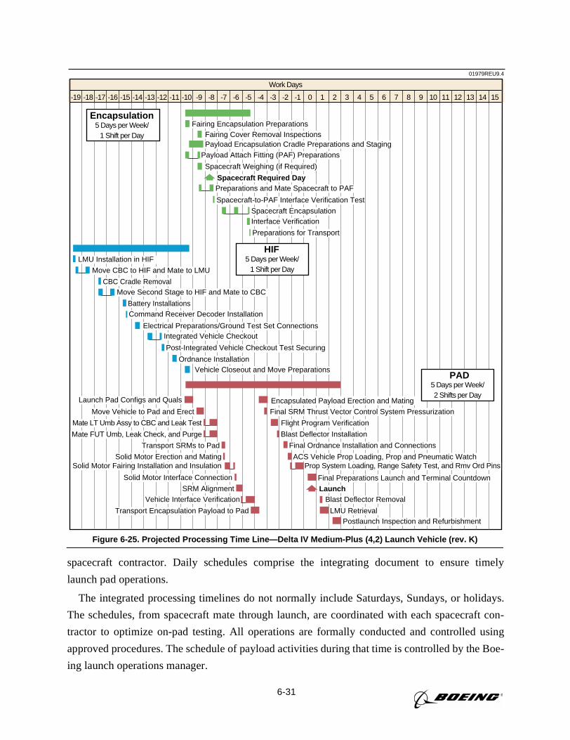
6-31
spacecraft contractor. Daily schedules comprise the integrating document to ensure timely
launch pad operations.
The integrated processing timelines do not normally include Saturdays, Sundays, or holidays.
The schedules, from spacecraft mate through launch, are coordinated with each spacecraft con-
tractor to optimize on-pad testing. All operations are formally conducted and controlled using
approved procedures. The schedule of payload activities during that time is controlled by the Boe-
ing launch operations manager.
01979REU9.4
Work Days
-12-13-14-15-16-17-18-19 -11 -10 -9 -8 -7 -6 -5 -4 -3 -2 -1 0 1 2 3 4 5 7 8 9 10 11 12 13 14 156
Fairing Encapsulation PreparationsFairing Cover Removal Inspections
Spacecraft-to-PAF Interface Verification Test
Interface Verification
Payload Encapsulation Cradle Preparations and StagingPayload Attach Fitting (PAF) Preparations
Spacecraft Required DayPreparations and Mate Spacecraft to PAF
Spacecraft Encapsulation
Preparations for Transport
Spacecraft Weighing (if Required)
Encapsulation5 Days per Week/
1 Shift per Day
Move CBC to HIF and Mate to LMU
CBC Cradle RemovalMove Second Stage to HIF and Mate to CBC
Battery Installations
LMU Installation in HIF
Ordnance InstallationVehicle Closeout and Move Preparations
Command Receiver Decoder Installation
Electrical Preparations/Ground Test Set ConnectionsIntegrated Vehicle Checkout
Post-Integrated Vehicle Checkout Test Securing
HIF5 Days per Week/
1 Shift per Day
Launch Pad Configs and Quals
Move Vehicle to Pad and Erect Final SRM Thrust Vector Control System Pressurization
Mate LT Umb Assy to CBC and Leak Test
Encapsulated Payload Erection and Mating
Flight Program Verification
Mate FUT Umb, Leak Check, and Purge Blast Deflector Installation
Transport SRMs to Pad Final Ordnance Installation and Connections
Postlaunch Inspection and Refurbishment
Solid Motor Erection and Mating ACS Vehicle Prop Loading, Prop and Pneumatic WatchSolid Motor Fairing Installation and Insulation
Solid Motor Interface Connection
SRM Alignment
Prop System Loading, Range Safety Test, and Rmv Ord Pins
Vehicle Interface Verification Blast Deflector Removal
Final Preparations Launch and Terminal Countdown
LMU Retrieval
Launch
Transport Encapsulation Payload to Pad
PAD5 Days per Week/2 Shifts per Day
Figure 6-25. Projected Processing Time Line—Delta IV Medium-Plus (4,2) Launch Vehicle (rev. K)
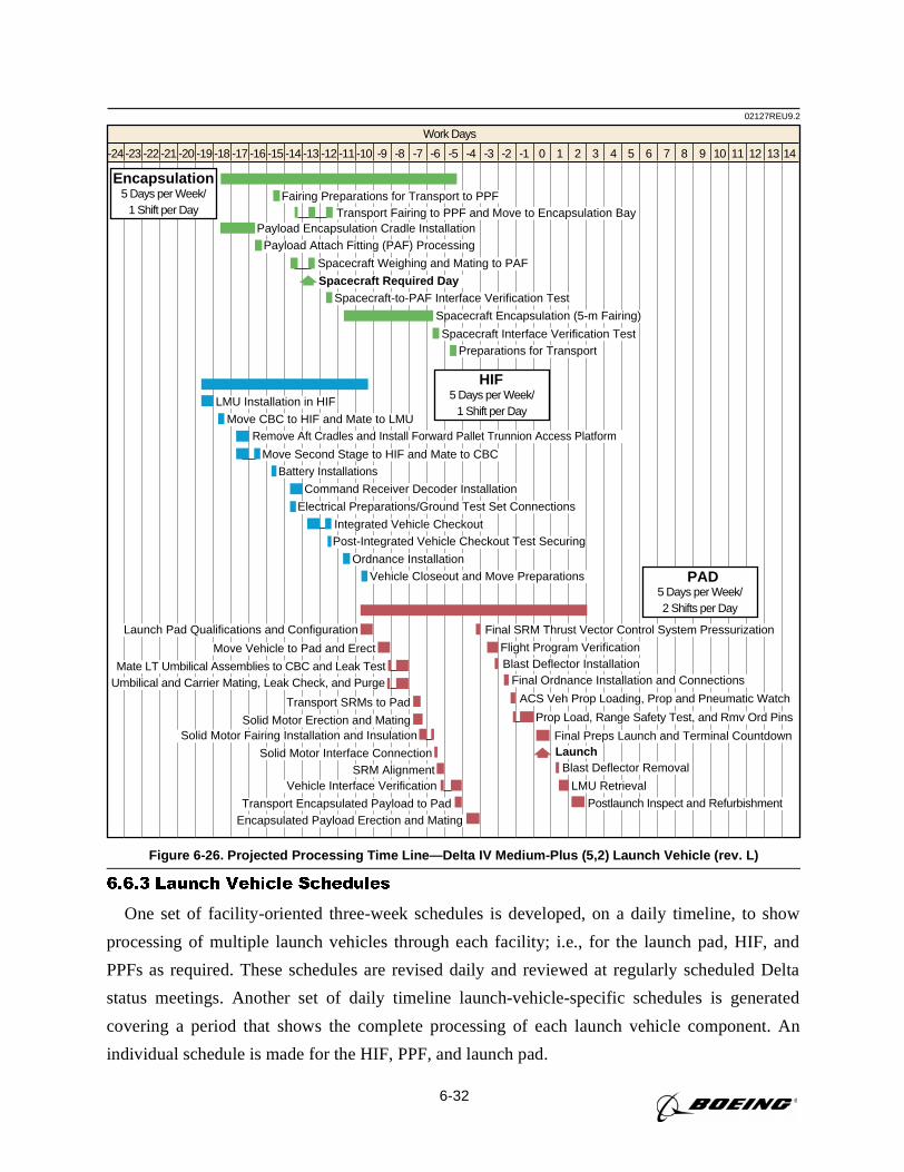
6-32
6.6.3 Launch Vehicle Schedules
One set of facility-oriented three-week schedules is developed, on a daily timeline, to show
processing of multiple launch vehicles through each facility; i.e., for the launch pad, HIF, and
PPFs as required. These schedules are revised daily and reviewed at regularly scheduled Delta
status meetings. Another set of daily timeline launch-vehicle-specific schedules is generated
covering a period that shows the complete processing of each launch vehicle component. An
individual schedule is made for the HIF, PPF, and launch pad.
Work Days
-24 -23 -22 -21 -20 -19 -18 -17 -16 -15 -14 -13 -12 -11 -10 -9 -8 -7 -6 -5 -4 -3 -2 -1 0 1 2 3 4 5 6 7 8 9 10 11 12 1413
Fairing Preparations for Transport to PPFTransport Fairing to PPF and Move to Encapsulation Bay
Spacecraft Encapsulation (5-m Fairing)
Payload Encapsulation Cradle InstallationPayload Attach Fitting (PAF) Processing
Spacecraft Required DaySpacecraft-to-PAF Interface Verification Test
Spacecraft Interface Verification TestPreparations for Transport
Spacecraft Weighing and Mating to PAF
Encapsulation5 Days per Week/
1 Shift per Day
Move CBC to HIF and Mate to LMURemove Aft Cradles and Install Forward Pallet Trunnion Access Platform
Move Second Stage to HIF and Mate to CBC
Battery Installations
LMU Installation in HIF
Ordnance Installation
Vehicle Closeout and Move Preparations
Command Receiver Decoder Installation
Electrical Preparations/Ground Test Set Connections
Integrated Vehicle CheckoutPost-Integrated Vehicle Checkout Test Securing
HIF5 Days per Week/
1 Shift per Day
Launch Pad Qualifications and Configuration
Move Vehicle to Pad and Erect Flight Program Verification
Mate LT Umbilical Assemblies to CBC and Leak Test
Final SRM Thrust Vector Control System Pressurization
Umbilical and Carrier Mating, Leak Check, and Purge
Transport SRMs to Pad
Solid Motor Erection and Mating
SRM Alignment
Solid Motor Fairing Installation and Insulation
Transport Encapsulated Payload to PadEncapsulated Payload Erection and Mating
Solid Motor Interface Connection
Vehicle Interface Verification
Final Ordnance Installation and ConnectionsBlast Deflector Installation
ACS Veh Prop Loading, Prop and Pneumatic Watch
Prop Load, Range Safety Test, and Rmv Ord Pins
Final Preps Launch and Terminal CountdownLaunch
Blast Deflector Removal
LMU Retrieval
Postlaunch Inspect and Refurbishment
PAD5 Days per Week/2 Shifts per Day
02127REU9.2
Figure 6-26. Projected Processing Time Line—Delta IV Medium-Plus (5,2) Launch Vehicle (rev. L)
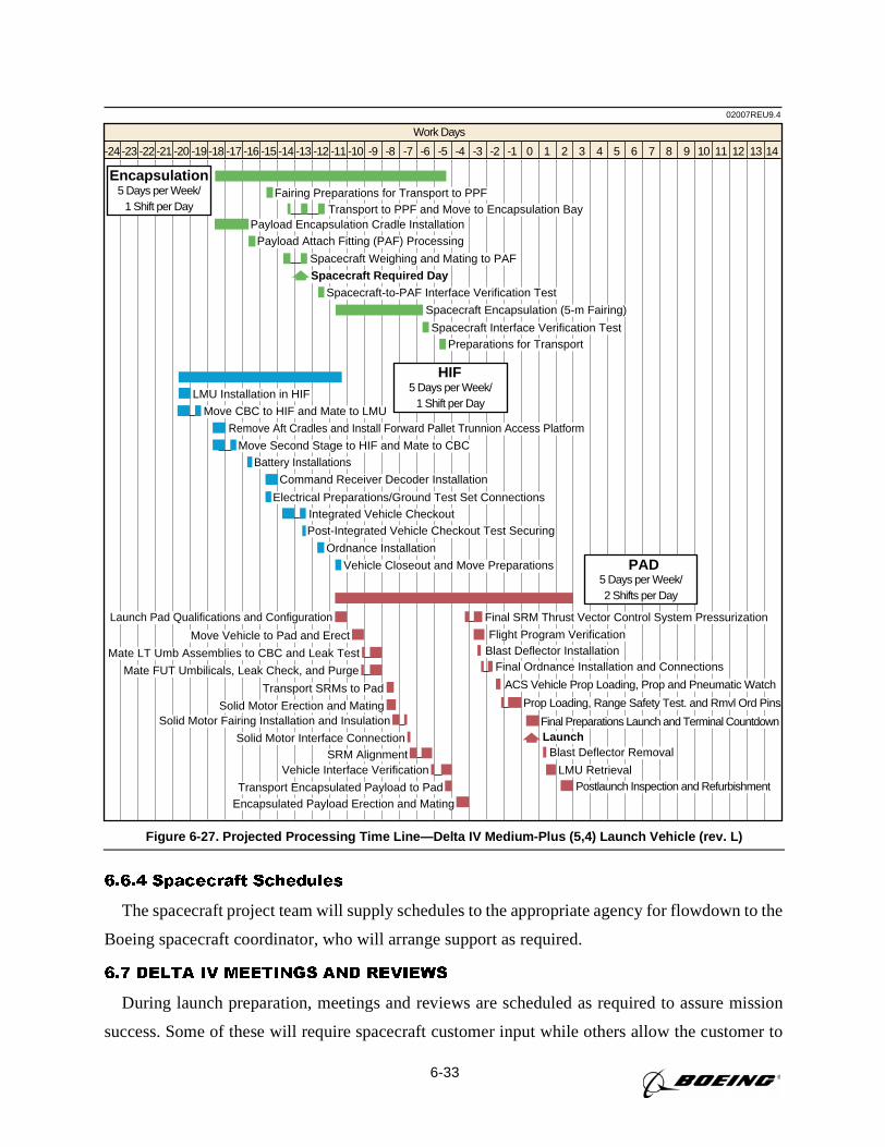
6-33
6.6.4 Spacecraft Schedules
The spacecraft project team will supply schedules to the appropriate agency for flowdown to the
Boeing spacecraft coordinator, who will arrange support as required.
6.7 DELTA IV MEETINGS AND REVIEWS
During launch preparation, meetings and reviews are scheduled as required to assure mission
success. Some of these will require spacecraft customer input while others allow the customer to
02007REU9.4
Work Days
-24 -23 -22 -21 -20 -19 -18 -17 -16 -15 -14 -13 -12 -11 -10 -9 -8 -7 -6 -5 -4 -3 -2 -1 0 1 2 3 4 5 6 7 8 9 10 11 12 1413
Fairing Preparations for Transport to PPFTransport to PPF and Move to Encapsulation Bay
Spacecraft Encapsulation (5-m Fairing)
Payload Encapsulation Cradle InstallationPayload Attach Fitting (PAF) Processing
Spacecraft Required DaySpacecraft-to-PAF Interface Verification Test
Spacecraft Interface Verification TestPreparations for Transport
Spacecraft Weighing and Mating to PAF
Encapsulation5 Days per Week/
1 Shift per Day
Move CBC to HIF and Mate to LMU
Remove Aft Cradles and Install Forward Pallet Trunnion Access Platform
Move Second Stage to HIF and Mate to CBC
Battery Installations
LMU Installation in HIF
Ordnance Installation
Vehicle Closeout and Move Preparations
Command Receiver Decoder Installation
Electrical Preparations/Ground Test Set ConnectionsIntegrated Vehicle CheckoutPost-Integrated Vehicle Checkout Test Securing
HIF5 Days per Week/
1 Shift per Day
Launch Pad Qualifications and Configuration
Move Vehicle to Pad and Erect Flight Program Verification
Mate LT Umb Assemblies to CBC and Leak Test
Final SRM Thrust Vector Control System Pressurization
Mate FUT Umbilicals, Leak Check, and Purge
Transport SRMs to Pad
Solid Motor Erection and Mating
SRM Alignment
Solid Motor Fairing Installation and Insulation
Transport Encapsulated Payload to PadEncapsulated Payload Erection and Mating
Solid Motor Interface Connection
Vehicle Interface Verification
Final Ordnance Installation and ConnectionsBlast Deflector Installation
ACS Vehicle Prop Loading, Prop and Pneumatic Watch
Prop Loading, Range Safety Test. and Rmvl Ord Pins
Final Preparations Launch and Terminal CountdownLaunch
Blast Deflector Removal
LMU RetrievalPostlaunch Inspection and Refurbishment
PAD5 Days per Week/2 Shifts per Day
Figure 6-27. Projected Processing Time Line—Delta IV Medium-Plus (5,4) Launch Vehicle (rev. L)
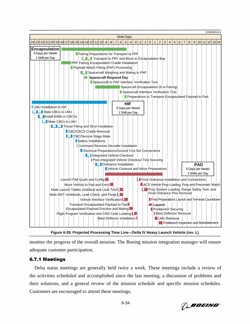
6-34
monitor the progress of the overall mission. The Boeing mission integration manager will ensure
adequate customer participation.
6.7.1 Meetings
Delta status meetings are generally held twice a week. These meetings include a review of
the activities scheduled and accomplished since the last meeting, a discussion of problems and
their solutions, and a general review of the mission schedule and specific mission schedules.
Customers are encouraged to attend these meetings.
01980REU9.4
Work Days
-24 -23 -22 -21 -20 -19 -18 -17 -16 -15 -14 -13 -12 -11 -10 -9 -8 -7 -6 -5 -4 -3 -2 -1 0 1 2 3 4 5 6 7 8 9 10 11 12 1413
Fairing Preparations for Transport to PPFTransport to PPF and Move to Encapsulation Bay
Spacecraft Encapsulation (5-m Fairing)
PPF Fairing Encapsulation Cradle InstallationPayload Attach Fitting (PAF) Processing
Spacecraft Required DaySpacecraft to PAF Interface Verification Test
Spacecraft Interface Verification TestPreparations to Transport Encapsulated Payload to Pad
Spacecraft Weighing and Mating to PAF
Encapsulation5 Days per Week/
1 Shift per Day
Mate CBCs to LMUInstall BSMs in CBCSs
Mate CBCs to LMU
Battery Installations
LMU Installation in HIF
Ordnance InstallationVehicle Closeout and Move Preparations
Command Receiver Decoder Installation
CBC/CBCS Cradle Removal
Thrust Fitting and Strut Installation
CBC/Second-Stage Mate
Electrical Preparations/Ground Test Set ConnectionsIntegrated Vehicle CheckoutPost-Integrated Vehicle Checkout Test Securing
HIF5 Days per Week/
1 Shift per Day
Launch Pad Quals and Config
Move Vehicle to Pad and Erect
Final Ordnance Installation and Connections
Mate Launch Tables Umbilical and Leak Test
ACS Vehicle Prop Loading, Prop and Pneumatic Watch
Mate MST Umbilicals, Leak Check, and Purge
Prop System Loading, Range Safety Test, andFinal Ordnance Pins Removal
Vehicle Interface Verification Final Preparations Launch and Terminal Countdown
Postlaunch SecuringTransport Encapsulated Payload to Pad
Blast Deflector Installation
LaunchEncapsulated Payload Erection and Mating
Flight Program Verification and CRD Code Loading Blast Deflector Removal
LMU RetrievalPostlaunch Inspection and Refurbishment
PAD5 Days per Week/2 Shifts per Day
Figure 6-28. Projected Processing Time Line—Delta IV Heavy Launch Vehicle (rev. L)
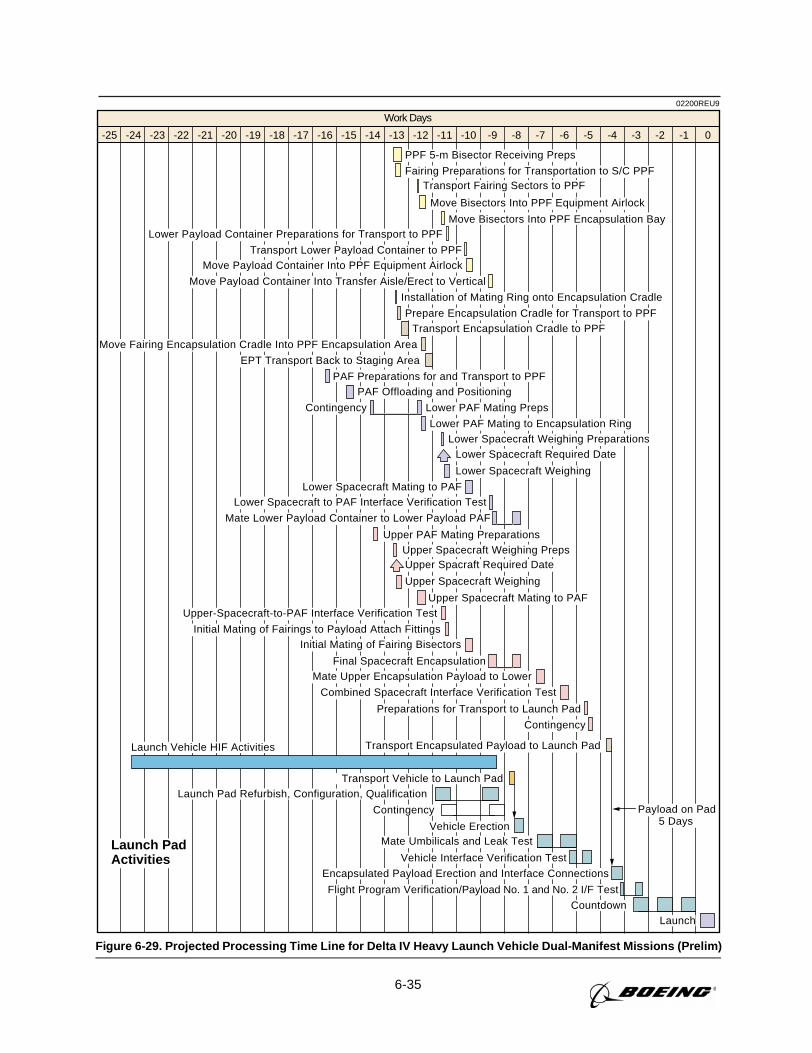
6-35
02200REU9
Work Days
-25 -24 -23 -22 -21 -20 -19 -18 -17 -16 -15 -14 -13 -12 -11 -10 -9 -8 -7 -6 -5 -4 -3 -1-2 0
Launch PadActivities
Transport Encapsulated Payload to Launch Pad
PPF 5-m Bisector Receiving Preps
Fairing Preparations for Transportation to S/C PPF
Move Bisectors Into PPF Encapsulation Bay
Installation of Mating Ring onto Encapsulation Cradle
Lower PAF Mating to Encapsulation RingLower Spacecraft Weighing Preparations
Lower Spacecraft Required Date
Lower Spacecraft Weighing
PAF Preparations for and Transport to PPFPAF Offloading and Positioning
Lower PAF Mating PrepsContingency
Prepare Encapsulation Cradle for Transport to PPFTransport Encapsulation Cradle to PPF
Move Fairing Encapsulation Cradle Into PPF Encapsulation Area
Lower Spacecraft Mating to PAFLower Spacecraft to PAF Interface Verification Test
Mate Lower Payload Container to Lower Payload PAF
Upper-Spacecraft-to-PAF Interface Verification Test
Initial Mating of Fairings to Payload Attach FittingsInitial Mating of Fairing Bisectors
Final Spacecraft EncapsulationMate Upper Encapsulation Payload to Lower
Combined Spacecraft Interface Verification Test
Preparations for Transport to Launch Pad
Contingency
Upper PAF Mating PreparationsUpper Spacecraft Weighing PrepsUpper Spacraft Required Date
Upper Spacecraft Weighing
Upper Spacecraft Mating to PAF
EPT Transport Back to Staging Area
Lower Payload Container Preparations for Transport to PPF
Transport Lower Payload Container to PPFMove Payload Container Into PPF Equipment Airlock
Move Payload Container Into Transfer Aisle/Erect to Vertical
Transport Fairing Sectors to PPF
Move Bisectors Into PPF Equipment Airlock
Launch Pad Refurbish, Configuration, Qualification
Contingency
Vehicle Erection
Vehicle Interface Verification Test
Encapsulated Payload Erection and Interface Connections
Flight Program Verification/Payload No. 1 and No. 2 I/F Test
Transport Vehicle to Launch Pad
Launch
Launch Vehicle HIF Activities
Mate Umbilicals and Leak Test
Countdown
Payload on Pad5 Days
Figure 6-29. Projected Processing Time Line for Delta IV Heavy Launch Vehicle Dual-Manifest Missions (Prelim)
6-36
Daily schedule meetings are held to provide the team members with their assignments and to
summarize the previous or current day’s accomplishments. These meetings are attended by the
launch conductor, technicians, inspectors, engineers, supervisors, and the spacecraft coordinator.
Depending on testing activities, these meetings are held at the beginning of the first shift.
6.7.2 Prelaunch Review Process
Periodic reviews are held to ensure that the payload and launch vehicle are ready for launch.
The mission plan will show the relationship of the reviews to the program assembly and test flow.
The following paragraphs discuss the Delta IV readiness reviews.
6.7.2.1 Postproduction Review. This meeting, conducted at Decatur, Alabama, reviews the
flight hardware at the end of production and prior to shipment to CCAS.
6.7.2.2 Mission Analysis Review. This meeting is held at Huntington Beach, California,
approximately three months prior to launch to review mission-specific drawings, studies, and
analyses.
6.7.2.3 Pre-Vehicle-On-Stand Review. A pre-vehicle-on-stand (pre-VOS) review is held
at CCAS subsequent to the completion of HIF processing and prior to erection of the vehicle on
the launch pad. It includes an update of the activities since manufacturing, the results of HIF pro-
cessing, and hardware history changes. Launch facility readiness is also discussed. (Pre-VOS
occurs approximately at L-12.)
6.7.2.4 Flight Readiness Review. Flight readiness review (FRR) is a status of the launch
vehicle after HIF processing and a mission analysis update. It is conducted to determine that the
launch vehicle and payload are ready for countdown and launch. Upon completion of this review,
authorization to proceed with the final phases of countdown preparation is given. This review also
assesses the readiness of the range to support launch and provides predicted weather data. (FRR
occurs at L-2 days.)
6.7.2.5 Launch Readiness Review. Launch readiness review (LRR) is held on L-1 day.
All agencies and contractors are required to provide a ready-to-launch statement. Upon comple-
tion of this meeting, authorization to enter terminal countdown is given.
7-1
Section 7
LAUNCH OPERATIONS AT WESTERN RANGE
This section presents a description of Delta launch vehicle operations associated with Space
Launch Complex 6 (SLC-6) at Vandenberg Air Force Base (VAFB), California. Prelaunch pro-
cessing of the Delta IV launch system is discussed, as are payload processing and operations con-
ducted prior to launch day.
7.1 ORGANIZATIONS
As operator of the Delta IV launch system, Boeing maintains an operations team at VAFB that
provides launch services to the United States Air Force (USAF), National Aeronautics and Space
Administration (NASA), and commercial customers. Boeing provides the interface to the Federal
Aviation Administration (FAA) and Department of Transportation (DOT) for licensing and certi-
fication to launch commercial payloads using the Delta IV family of launch vehicles.
Boeing has established an interface with the USAF 30th Space Wing Directorate of Plans; the West-
ern Range has designated a range program support manager (PSM) to represent the 30th Space Wing.
The PSM serves as the official interface for all launch support and services requested. These services
include range instrumentation, facilities/equipment operation and maintenance, safety, security, and
logistics support. Requirements for range services are described in documents prepared and submitted
to the government by Boeing, based on inputs from the spacecraft contractor (the launch vehicle
builder), using the government’s universal documentation system (UDS) format (seeSection 8, Pay-
load Integration). Boeing and the spacecraft contractor generate the program requirements document
(PRD). Formal submittal of these documents to the government agencies is arranged by Boeing.
For commercial launches, Boeing makes all the arrangements for the payload processing facil-
ities (PPF) and services. The organizations that support a launch from VAFB are listed inFig-
ure 7-1. For each mission, a spacecraft coordinator from the Boeing VAFB launch team is
assigned to assist the spacecraft team during the launch campaign by helping to obtain safety
approval of the payload test procedures and operations; integrating the spacecraft operations into
the launch vehicle activities; and, during the countdown and launch, serving as the interface
between the payload and test conductor in the launch control center (LCC). Boeing interfaces
with NASA at VAFB through the VAFB Kennedy Space Center (KSC) resident office.
7.2 FACILITIES
In addition to facilities required for Delta IV launch vehicle processing, specialized PPFs are
provided for checkout and preparation of the payload. Laboratories, clean rooms, receiving and
shipping areas, hazardous operations areas, and offices are provided for payload project personnel.
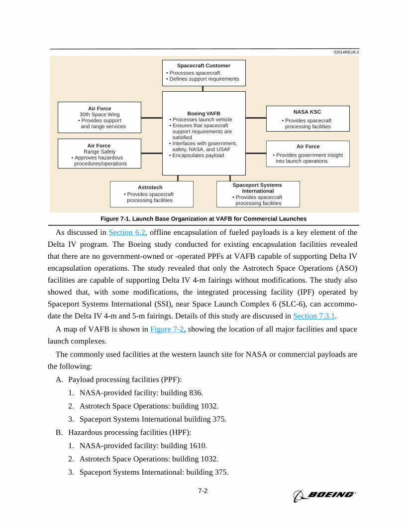
7-2
As discussed inSection 6.2, offline encapsulation of fueled payloads is a key element of the
Delta IV program. The Boeing study conducted for existing encapsulation facilities revealed
that there are no government-owned or -operated PPFs at VAFB capable of supporting Delta IV
encapsulation operations. The study revealed that only the Astrotech Space Operations (ASO)
facilities are capable of supporting Delta IV 4-m fairings without modifications. The study also
showed that, with some modifications, the integrated processing facility (IPF) operated by
Spaceport Systems International (SSI), near Space Launch Complex 6 (SLC-6), can accommo-
date the Delta IV 4-m and 5-m fairings. Details of this study are discussed inSection 7.3.1.
A map of VAFB is shown inFigure 7-2, showing the location of all major facilities and space
launch complexes.
The commonly used facilities at the western launch site for NASA or commercial payloads are
the following:
A. Payload processing facilities (PPF):
1. NASA-provided facility: building 836.
2. Astrotech Space Operations: building 1032.
3. Spaceport Systems International building 375.
B. Hazardous processing facilities (HPF):
1. NASA-provided facility: building 1610.
2. Astrotech Space Operations: building 1032.
3. Spaceport Systems International: building 375.
02014REU9.3
NASA KSC Air Force
30th Space Wing• Provides support
and range services
Spacecraft Customer• Processes spacecraft• Defines support requirements
Air Force Range Safety
• Approves hazardous procedures/operations
Boeing VAFB• Processes launch vehicle• Ensures that spacecraft
support requirements are • satisfied
• Interfaces with government, • safety, NASA, and USAF
• Encapsulates payload
Spaceport Systems International
Air Force
• Provides government insight into launch operations
• Provides spacecraft processing facilities
Astrotech• Provides spacecraft processing facilities
• Provides spacecraft processing facilities
Figure 7-1. Launch Base Organization at VAFB for Commercial Launches
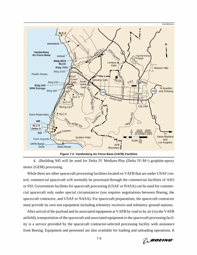
7-3
4. (Building 945 will be used for Delta IV Medium-Plus (Delta IV-M+) graphite-epoxy
motor (GEM) processing.
While there are other spacecraft processing facilities located on VAFB that are under USAF con-
trol, commercial spacecraft will normally be processed through the commercial facilities of ASO
or SSI. Government facilities for spacecraft processing (USAF or NASA) can be used for commer-
cial spacecraft only under special circumstances (use requires negotiations between Boeing, the
spacecraft contractor, and USAF or NASA). For spacecraft preparations, the spacecraft contractor
must provide its own test equipment including telemetry receivers and telemetry ground stations.
After arrival of the payload and its associated equipment at VAFB by road or by air (via the VAFB
airfield), transportation of the spacecraft and associated equipment to the spacecraft processing facil-
ity is a service provided by the spacecraft contractor-selected processing facility with assistance
from Boeing. Equipment and personnel are also available for loading and unloading operations. It
01976REU9.4
SLC-3
SLC-2
SLC-4
SLC-5
Boat House
Pacific Ocean
Scale
0 (6,000)(12,000)0 1829 3659
VandenbergAir Force Base Airfield
Bldg 8510RLCC
VAFB BargeDock
1
1
1
Spring Can yon
RdS
urfR
d
Honda Ridge RdTra
nqilli
an
Mtn
Rd
Coa
stR
d
Mig uelli
toR
d
Sa n taYnez River
Sa
n taLucia
Canyon
Rd
SanY
nezR
idge
Rd
Ocean Ave
Solvang Gate
Sudden Flats
Mission Hills
To Buelltonand Solvang
LompocGate
Lompoc
City Hall
Oil Well Canyon
PineC
a
nyon
ToSanta Barbara
andLos Angeles
SurfCoastGate South
VAFBGate
AFBBoundary
246246
Point Arguello
VandenbergVillage
Astrotech
Bldg 7525
Bldg 2520
Bldg 836Bldg 945
SRM StorageBldg 960
PacificR
SSI
SLC-6Delta IV
HIF
m(ft)
Bear Cree k Rd
N
Point Pedernales
Figure 7-2. Vandenberg Air Force Base (VAFB) Facilities
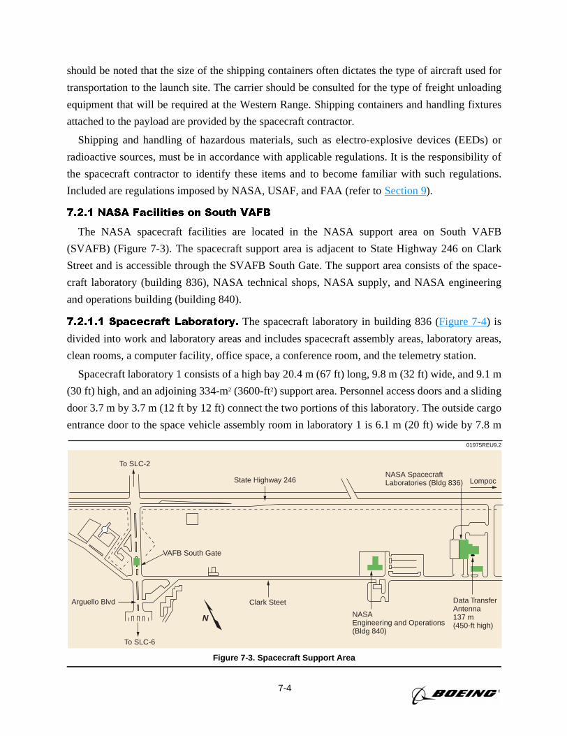
7-4
should be noted that the size of the shipping containers often dictates the type of aircraft used for
transportation to the launch site. The carrier should be consulted for the type of freight unloading
equipment that will be required at the Western Range. Shipping containers and handling fixtures
attached to the payload are provided by the spacecraft contractor.
Shipping and handling of hazardous materials, such as electro-explosive devices (EEDs) or
radioactive sources, must be in accordance with applicable regulations. It is the responsibility of
the spacecraft contractor to identify these items and to become familiar with such regulations.
Included are regulations imposed by NASA, USAF, and FAA (refer toSection 9).
7.2.1 NASA Facilities on South VAFB
The NASA spacecraft facilities are located in the NASA support area on South VAFB
(SVAFB) (Figure 7-3). The spacecraft support area is adjacent to State Highway 246 on Clark
Street and is accessible through the SVAFB South Gate. The support area consists of the space-
craft laboratory (building 836), NASA technical shops, NASA supply, and NASA engineering
and operations building (building 840).
7.2.1.1 Spacecraft Laboratory. The spacecraft laboratory in building 836 (Figure 7-4) is
divided into work and laboratory areas and includes spacecraft assembly areas, laboratory areas,
clean rooms, a computer facility, office space, a conference room, and the telemetry station.
Spacecraft laboratory 1 consists of a high bay 20.4 m (67 ft) long, 9.8 m (32 ft) wide, and 9.1 m
(30 ft) high, and an adjoining 334-m2 (3600-ft2) support area. Personnel access doors and a sliding
door 3.7 m by 3.7 m (12 ft by 12 ft) connect the two portions of this laboratory. The outside cargo
entrance door to the space vehicle assembly room in laboratory 1 is 6.1 m (20 ft) wide by 7.8 m
01975REU9.2
NASA SpacecraftLaboratories (Bldg 836) LompocState Highway 246
To SLC-2
VAFB South Gate
Arguello Blvd Clark Steet
To SLC-6
NASAEngineering and Operations(Bldg 840)
Data TransferAntenna137 m(450-ft high)
N
Figure 7-3. Spacecraft Support Area
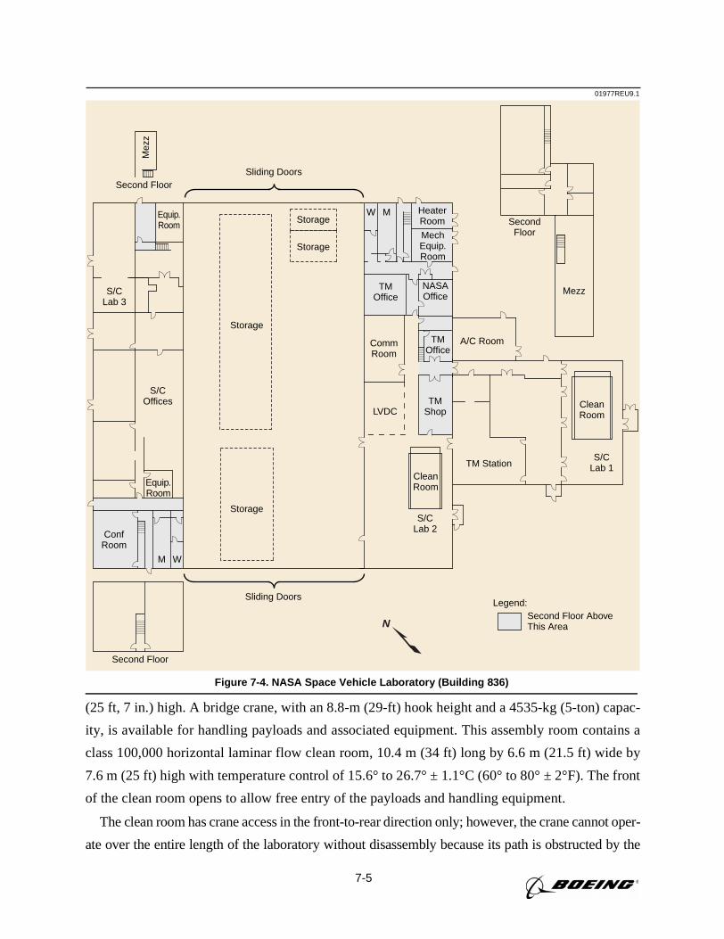
7-5
(25 ft, 7 in.) high. A bridge crane, with an 8.8-m (29-ft) hook height and a 4535-kg (5-ton) capac-
ity, is available for handling payloads and associated equipment. This assembly room contains a
class 100,000 horizontal laminar flow clean room, 10.4 m (34 ft) long by 6.6 m (21.5 ft) wide by
7.6 m (25 ft) high with temperature control of 15.6° to 26.7° ± 1.1°C (60° to 80° ± 2°F). The front
of the clean room opens to allow free entry of the payloads and handling equipment.
The clean room has crane access in the front-to-rear direction only; however, the crane cannot oper-
ate over the entire length of the laboratory without disassembly because its path is obstructed by the
01977REU9.1
Second Floor
S/COffices
S/CLab 3
Mez
z
Second Floor
Storage
Storage
Storage
Storage
Legend:Second Floor AboveThis Area
Equip.Room
Equip.Room
Sliding Doors
Sliding Doors
ConfRoom
M W
S/CLab 2
TM Station
SecondFloor
Mezz
S/CLab 1
A/C Room
CleanRoom
CleanRoom
LVDC
HeaterRoom
MechEquip.Room
TMOffice
NASAOffice
TMOffice
CommRoom
TMShop
W M
N
Figure 7-4. NASA Space Vehicle Laboratory (Building 836)
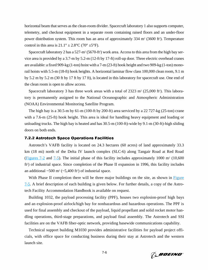
7-6
horizontal beam that serves as the clean-room divider. Spacecraft laboratory 1 also supports computer,
telemetry, and checkout equipment in a separate room containing raised floors and an under-floor
power distribution system. This room has an area of approximately 334 m2 (3600 ft2). Temperature
control in this area is 21.1° ± 2.8°C (70° ±5°F).
Spacecraft laboratory 2 has a 527-m2 (5670-ft2) work area. Access to this area from the high bay ser-
vice area is provided by a 3.7-m by 5.2-m (12-ft by 17-ft) roll-up door. Three electric overhead cranes
are available: a fixed 909-kg (1-ton) hoist with a 7-m (23-ft) hook height and two 909-kg (1-ton) mono-
rail hoists with 5.5-m (18-ft) hook heights. A horizontal laminar flow class 100,000 clean room, 9.1 m
by 5.2 m by 5.2 m (30 ft by 17 ft by 17 ft), is located in this laboratory for spacecraft use. One end of
the clean room is open to allow access.
Spacecraft laboratory 3 has three work areas with a total of 2323 m2 (25,000 ft2). This labora-
tory is permanently assigned to the National Oceanographic and Atmospheric Administration
(NOAA) Environmental Monitoring Satellite Program.
The high bay is a 30.5-m by 61-m (100-ft by 200-ft) area serviced by a 22 727-kg (25-ton) crane
with a 7.6-m (25-ft) hook height. This area is ideal for handling heavy equipment and loading or
unloading trucks. The high bay is heated and has 30.5-m (100-ft)-wide by 9.1-m (30-ft)-high sliding
doors on both ends.
7.2.2 Astrotech Space Operations Facilities
Astrotech’s VAFB facility is located on 24.3 hectares (60 acres) of land approximately 33.3
km (18 mi) north of the Delta IV launch complex (SLC-6) along Tangair Road at Red Road
(Figures 7-2and 7-5). The initial phase of this facility includes approximately 1000 m2 (10,600
ft2) of industrial space. Since completion of the Phase II expansion in 1996, this facility includes
an additional ~500 m2 (~5,400 ft2) of industrial space.
With Phase II completion there will be three major buildings on the site, as shown inFigure
7-5. A brief description of each building is given below. For further details, a copy of the Astro-
tech Facility Accommodation Handbook is available on request.
Building 1032, the payload processing facility (PPF), houses two explosion-proof high bays
and an explosion-proof airlock/high bay for nonhazardous and hazardous operations. The PPF is
used for final assembly and checkout of the payload, liquid propellant and solid rocket motor han-
dling operations, third-stage preparations, and payload final assembly. The Astrotech and SSI
facilities are on the VAFB fiber-optic network, providing basewide communications capability.
Technical support building M1030 provides administrative facilities for payload project offi-
cials, with office space for conducting business during their stay at Astrotech and the western
launch site.
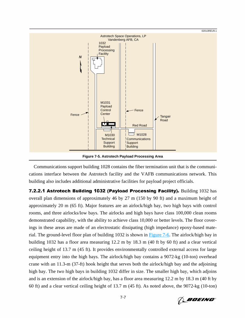
7-7
Communications support building 1028 contains the fiber termination unit that is the communi-
cations interface between the Astrotech facility and the VAFB communications network. This
building also includes additional administrative facilities for payload project officials.
7.2.2.1 Astrotech Building 1032 (Payload Processing Facility). Building 1032 has
overall plan dimensions of approximately 46 by 27 m (150 by 90 ft) and a maximum height of
approximately 20 m (65 ft). Major features are an airlock/high bay, two high bays with control
rooms, and three airlocks/low bays. The airlocks and high bays have class 100,000 clean rooms
demonstrated capability, with the ability to achieve class 10,000 or better levels. The floor cover-
ings in these areas are made of an electrostatic dissipating (high impedance) epoxy-based mate-
rial. The ground-level floor plan of building 1032 is shown inFigure 7-6. The airlock/high bay in
building 1032 has a floor area measuring 12.2 m by 18.3 m (40 ft by 60 ft) and a clear vertical
ceiling height of 13.7 m (45 ft). It provides environmentally controlled external access for large
equipment entry into the high bays. The airlock/high bay contains a 9072-kg (10-ton) overhead
crane with an 11.3-m (37-ft) hook height that serves both the airlock/high bay and the adjoining
high bay. The two high bays in building 1032 differ in size. The smaller high bay, which adjoins
and is an extension of the airlock/high bay, has a floor area measuring 12.2 m by 18.3 m (40 ft by
60 ft) and a clear vertical ceiling height of 13.7 m (45 ft). As noted above, the 9072-kg (10-ton)
02013REU9.1
Astrotech Space Operations, LPVandenberg AFB, CA
1032PayloadProcessingFacility
M1031PayloadControlCenter
FenceFence
Red Road
M1030Technical
SupportBuilding
M1028
TangairRoad
CommunicationsSupportBuilding
N
Figure 7-5. Astrotech Payload Processing Area
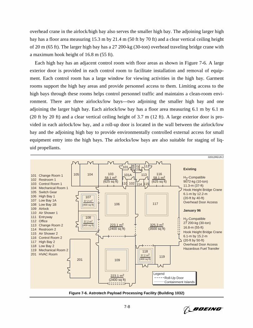
7-8
overhead crane in the airlock/high bay also serves the smaller high bay. The adjoining larger high
bay has a floor area measuring 15.3 m by 21.4 m (50 ft by 70 ft) and a clear vertical ceiling height
of 20 m (65 ft). The larger high bay has a 27 200-kg (30-ton) overhead traveling bridge crane with
a maximum hook height of 16.8 m (55 ft).
Each high bay has an adjacent control room with floor areas as shown in Figure 7-6. A large
exterior door is provided in each control room to facilitate installation and removal of equip-
ment. Each control room has a large window for viewing activities in the high bay. Garment
rooms support the high bay areas and provide personnel access to them. Limiting access to the
high bays through these rooms helps control personnel traffic and maintains a clean-room envi-
ronment. There are three airlocks/low bays—two adjoining the smaller high bay and one
adjoining the larger high bay. Each airlock/low bay has a floor area measuring 6.1 m by 6.1 m
(20 ft by 20 ft) and a clear vertical ceiling height of 3.7 m (12 ft). A large exterior door is pro-
vided in each airlock/low bay, and a roll-up door is located in the wall between the airlock/low
bay and the adjoining high bay to provide environmentally controlled external access for small
equipment entry into the high bays. The airlocks/low bays are also suitable for staging of liq-
uid propellants.
02012REU9.2
101102103104105106107108109110111112113114115116117118119201
Change Room 1Restroom 1Control Room 1Mechanical Room 1Switch GearHigh Bay 1Low Bay 1ALow Bay 1BAirlockAir Shower 1EntrywayOfficeChange Room 2Restroom 2Air Shower 2Control Room 2High Bay 2Low Bay 2Mechanical Room 2HVAC Room
105 104 101A 113
101
112
101B 111
110 102 114 115
119201
Legend Roll-Up Door Containment Islands
10737.2 m2
(400 sq ft)
10358.1 m2
(625 sq ft)
11658.1 m2
(625 sq ft)
10837.2 m2
(400 sq ft) 223.1 m2
(2400 sq ft)325.3 m2
(3500 sq ft)
106
223.1 m2
(2400 sq ft)
109
11837.2 m2
(400 sq ft)
117
Existing
H2-Compatible9072-kg (10-ton)11.3-m (37-ft) Hook Height Bridge Crane6.1-m by 12.2-m(20-ft by 40-ft) Overhead Door Access
January 96
H2-Compatible27 200-kg (30-ton)16.8-m (55-ft)Hook Height Bridge Crane6.1-m by 15.2-m(20-ft by 50-ft) Overhead Door AccessHazardous Fuel Transfer
Figure 7-6. Astrotech Payload Processing Facility (Building 1032)
7-9
7.2.2.2 Astrotech Building M1030 (Technical Support Building). Building M1030
provides 223 m2 (2400 ft2) of office and conference room space for the spacecraft project.
7.2.2.3 Astrotech Building 1028 (Communications Support Building). Building
1028 provides 111 m2 (1200 ft2) of office area for the spacecraft project.
7.2.3 Spaceport Systems International
Spaceport Systems International (SSI) is located immediately south of and adjacent to SLC-6
(Figure 7-2). The PPF associated with the California spaceport is located on South Vandenberg adja-
cent to the spaceport. This PPF is called the integrated processing facility (IPF) because booster
components and payloads (satellites) can be processed at the same time. Originally built to process
classified Space Shuttle payloads, this facility is now a part of SSI’s facilities. It has two basic areas:
processing, and technical support (Figure 7-7). The processing areas are on the north side of the
building, and the technical support areas are on the south side.
The cross-sectional view of the IPF shown inFigure 7-8illustrates the relationships between
the technical support area and the processing area level numbers. Level numbers are defined in
feet in reference to the SLC-6 launch mount. Rooms on two levels (89 and 101) provide office
space and technical support rooms ranging from 14 m2 to 150 m2 (150 ft2 to 1620 ft2). These floors
Security Office
Support Center OpsMgr
ConferenceRoom
FAXBreakRoom
Clean Room
Dressing Area
SecureClean Room
139.0 m2
(1495 sq ft)
MicRoom
Clean Room91.8 m2
(988 sq ft)
SecureOffice
104.6 m2
(1125 sq ft)
Secure Office14.1 m2
(152 sq ft)
MensRoom
Womens Room
Cell1
Cell2
Cell3
6902
High Bay9.14 m by 44.81 m
(30 ft by 147 ft)
10.7 m by 13.4 m(35 ft by 44 ft)
10.7 m by 13.4 m(35 ft by 44 ft)
Airlock 9.1 m by 30.5 m(30 ft by 100 ft)
SE Storage
Clean Elevator
68 040-kg (75-ton) Crane Envelope
4535-kg (5-ton) Crane Envelope
Payload Control Room6.4 m by 7.0 m(21 ft by 23 ft)
TransferTower Area
8.2 m by 9.1 m(27 ft by 30 ft)
AirLock
N
02018REU9.3
Figure 7-7. California Spaceport—Plan View of the Integrated Processing Facility
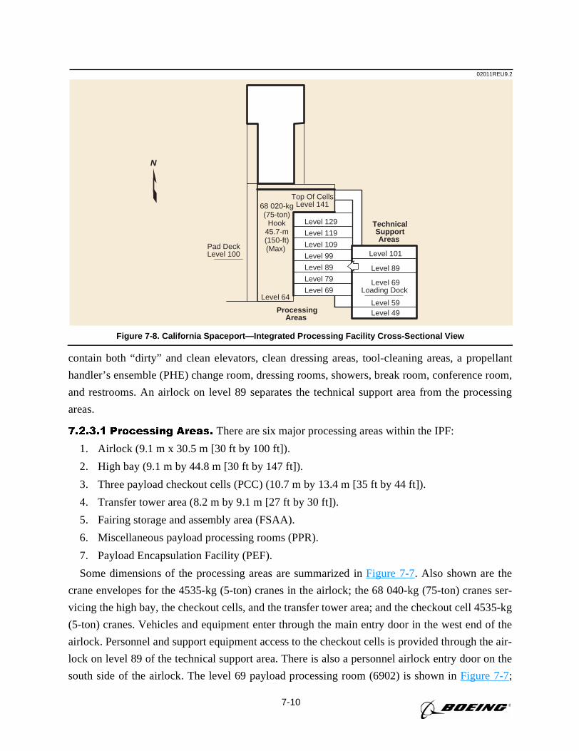
7-10
contain both “dirty” and clean elevators, clean dressing areas, tool-cleaning areas, a propellant
handler’s ensemble (PHE) change room, dressing rooms, showers, break room, conference room,
and restrooms. An airlock on level 89 separates the technical support area from the processing
areas.
7.2.3.1 Processing Areas. There are six major processing areas within the IPF:
1. Airlock (9.1 m x 30.5 m [30 ft by 100 ft]).
2. High bay (9.1 m by 44.8 m [30 ft by 147 ft]).
3. Three payload checkout cells (PCC) (10.7 m by 13.4 m [35 ft by 44 ft]).
4. Transfer tower area (8.2 m by 9.1 m [27 ft by 30 ft]).
5. Fairing storage and assembly area (FSAA).
6. Miscellaneous payload processing rooms (PPR).
7. Payload Encapsulation Facility (PEF).
Some dimensions of the processing areas are summarized inFigure 7-7. Also shown are the
crane envelopes for the 4535-kg (5-ton) cranes in the airlock; the 68 040-kg (75-ton) cranes ser-
vicing the high bay, the checkout cells, and the transfer tower area; and the checkout cell 4535-kg
(5-ton) cranes. Vehicles and equipment enter through the main entry door in the west end of the
airlock. Personnel and support equipment access to the checkout cells is provided through the air-
lock on level 89 of the technical support area. There is also a personnel airlock entry door on the
south side of the airlock. The level 69 payload processing room (6902) is shown inFigure 7-7;
02011REU9.2
Level 101
Level 89
Level 69Loading Dock
Level 59
TechnicalSupportAreas
ProcessingAreas
68 020-kg(75-ton)
Hook45.7-m(150-ft)(Max)
Level 64Level 69
Level 79
Level 89
Level 99
Level 109
Level 119
Level 129
Level 49
Pad DeckLevel 100
Top Of CellsLevel 141
N
Figure 7-8. California Spaceport—Integrated Processing Facility Cross-Sectional View
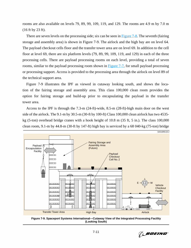
7-11
rooms are also available on levels 79, 89, 99, 109, 119, and 129. The rooms are 4.9 m by 7.0 m
(16 ft by 23 ft).
There are seven levels on the processing side; six can be seen inFigure 7-8. The seventh (fairing
storage and assembly area) is shown in Figure 7-9. The airlock and the high bay are on level 64.
The payload checkout cells floor and the transfer tower area are on level 69. In addition to the cell
floor at level 69, there are six platform levels (79, 89, 99, 109, 119, and 129) in each of the three
processing cells. There are payload processing rooms on each level, providing a total of seven
rooms, similar to the payload processing room shown inFigure 7-7, for small payload processing
or processing support. Access is provided to the processing area through the airlock on level 89 of
the technical support area.
Figure 7-9 illustrates the IPF as viewed in cutaway looking south, and shows the loca-
tion of the fairing storage and assembly area. This class 100,000 clean room provides the
option for fairing storage and build-up prior to encapsulating the payload in the transfer
tower area.
Access to the IPF is through the 7.3-m (24-ft)-wide, 8.5-m (28-ft)-high main door on the west
side of the airlock. The 9.1-m by 30.5-m (30-ft by 100-ft) Class 100,000 clean airlock has two 4535-
kg (5-ton) overhead bridge cranes with a hook height of 10.8 m (35 ft, 5 in.). The class 100,000
clean room, 9.1-m by 44.8-m (30-ft by 147-ft) high bay is serviced by a 68 040-kg (75-ton) bridge02010REU9.2
E W
Fairing Storage andAssembly Area(Future)
PayloadCheckoutCell No. 2
PayloadEncapsulation
Facility
Transfer Tower Area High Bay Airlock
VehicleCheckoutFacility
Figure 7-9. Spaceport Systems International—Cutaway View of the Integrated Processing Facility(Looking South)
7-12
crane. The hook height in the high bay is 26.3 m (86 ft, 4 in.). Access to the high bay is through the
7.3-m-(24-ft)-wide, 8.5-m (28-ft) door from the airlock.
The three class 100,000 clean-room (10.7-m by 13.4-m [35-ft by 44-ft]) payload checkout cells
(PCCs) are serviced by a 68 040-kg (75-ton) bridge crane with a 24.8-m (81-ft, 4-in.) hook height.
Each cell also has 4535-kg (5-ton) crane support with a hook height of 21.9 m (71 ft, 11 in.).
Access to each cell is through doors from the high bay with a total opening of 6.4 m (21 ft, 2 in.).
Tables 7-1, 7-2, 7-3, 7-4, 7-5, 7-6, and7-7 detail some of the capabilities in each of the processing
areas. They define constraints, customer-provided equipment, and technical capability summaries in
nine categories: space/access, handling, electrical, liquids, pneumatics, environmental control, safety,
security, and communications.
7.2.3.2 Technical Support Areas. Figures 7-10and7-11are plan views of the IPF, show-
ing levels 89 and 101 of the technical support side. (Level numbers are defined in feet, with the
SLC-6 launch mount defined as level 100.) These figures show room sizes as well as potential
functions. Note that the clean elevator can be accessed only from the technical support side on
level 89 through the airlock (for support equipment) or the clean change room. From the elevator,
any level on the processing side can be accessed.
7.3 PAYLOAD ENCAPSULATION AND TRANSPORT TO LAUNCH SITE
Delta IV provides fueled payload encapsulation in the fairing at the payload processing facility.
This capability enhances payload safety and security while mitigating contamination concerns,
and greatly reduces launch pad operations in the vicinity of the payload.
Payload integration with the PAF and encapsulation in the fairing is planned using either
Astrotech or SSI facilities for government, NASA, or commercial payloads. The Astrotech facil-
ities can accommodate payload encapsulation for 4-m fairing (Delta IV-M, Delta IV-M+[4,2])
launch vehicles, and with modifications, can accommodate all Delta IV launch vehicle configu-
rations. With modifications, the SSI facilities can also accommodate all Delta IV launch vehicle
configurations. For purposes of this document, discussions are limited to Astrotech and SSI
facilities.
Prior to or after payload arrival, the fairing and PAF(s) enter a high bay to be prepared for payload
encapsulation. The fairing bisectors or trisectors are erected and stored on roll transfer dollies. The
PAF is installed on the Boeing buildup stand and prepared for payload mate. After payload arrival
and premate operations are completed, including payload weighing if required (a certified weight
statement will suffice), the payload is mated to the PAF, and integrated checkout is performed. The
previously prepared fairing bisectors or trisectors are then rolled into position for final mate, and the
personnel access platforms are positioned for personnel access to the fairing mating plane. (These
access platforms can also be used for payload access prior to fairing mate.) Interface connections
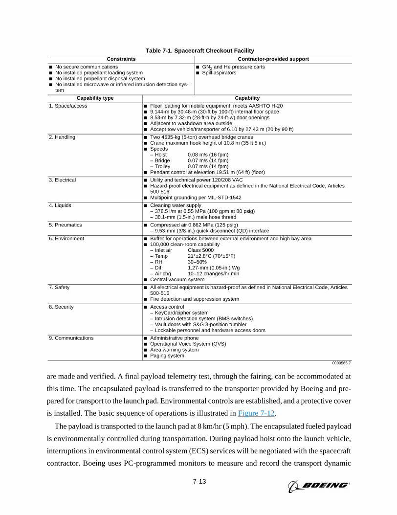
7-13
are made and verified. A final payload telemetry test, through the fairing, can be accommodated at
this time. The encapsulated payload is transferred to the transporter provided by Boeing and pre-
pared for transport to the launch pad. Environmental controls are established, and a protective cover
is installed. The basic sequence of operations is illustrated inFigure 7-12.
The payload is transported to the launch pad at 8 km/hr (5 mph). The encapsulated fueled payload
is environmentally controlled during transportation. During payload hoist onto the launch vehicle,
interruptions in environmental control system (ECS) services will be negotiated with the spacecraft
contractor. Boeing uses PC-programmed monitors to measure and record the transport dynamic
Table 7-1. Spacecraft Checkout FacilityConstraints Contractor-provided support
No secure communications No installed propellant loading system No installed propellant disposal system No installed microwave or infrared intrusion detection sys-
tem
GN2 and He pressure carts Spill aspirators
Capability type Capability
1. Space/access Floor loading for mobile equipment; meets AASHTO H-20 9.144-m by 30.48-m (30-ft by 100-ft) internal floor space 8.53-m by 7.32-m (28-ft-h by 24-ft-w) door openings Adjacent to washdown area outside Accept tow vehicle/transporter of 6.10 by 27.43 m (20 by 90 ft)
2. Handling Two 4535-kg (5-ton) overhead bridge cranes Crane maximum hook height of 10.8 m (35 ft 5 in.) Speeds
– Hoist 0.08 m/s (16 fpm)– Bridge 0.07 m/s (14 fpm)– Trolley 0.07 m/s (14 fpm)
Pendant control at elevation 19.51 m (64 ft) (floor)
3. Electrical Utility and technical power 120/208 VAC Hazard-proof electrical equipment as defined in the National Electrical Code, Articles
500-516 Multipoint grounding per MIL-STD-1542
4. Liquids Cleaning water supply– 378.5 l/m at 0.55 MPa (100 gpm at 80 psig)– 38.1-mm (1.5-in.) male hose thread
5. Pneumatics Compressed air 0.862 MPa (125 psig)– 9.53-mm (3/8-in.) quick-disconnect (QD) interface
6. Environment Buffer for operations between external environment and high bay area 100,000 clean-room capability
– Inlet air Class 5000– Temp 21°±2.8°C (70°±5°F)– RH 30–50%– Dif 1.27-mm (0.05-in.) Wg– Air chg 10–12 changes/hr min
Central vacuum system
7. Safety All electrical equipment is hazard-proof as defined in National Electrical Code, Articles500-516
Fire detection and suppression system
8. Security Access control– KeyCard/cipher system– Intrusion detection system (BMS switches)– Vault doors with S&G 3-position tumbler– Lockable personnel and hardware access doors
9. Communications Administrative phone Operational Voice System (OVS) Area warning system Paging system
0000566.7
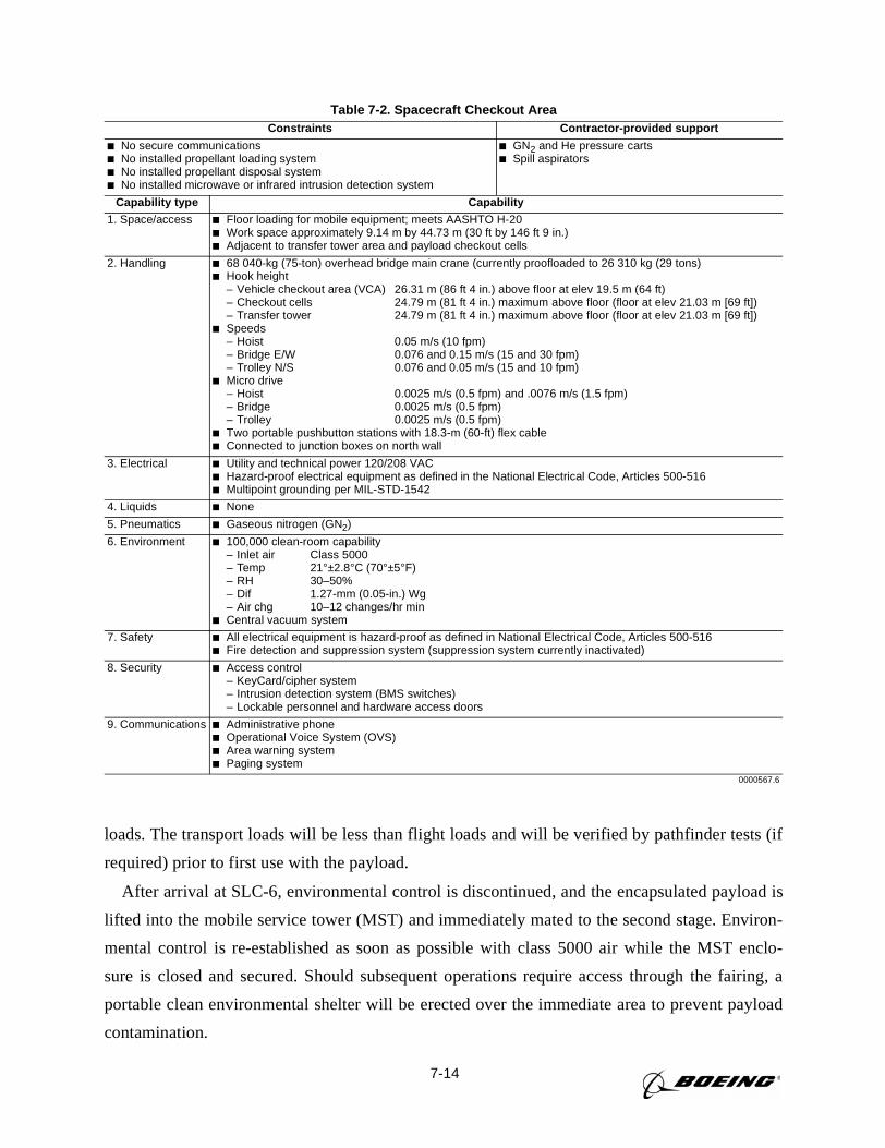
7-14
loads. The transport loads will be less than flight loads and will be verified by pathfinder tests (if
required) prior to first use with the payload.
After arrival at SLC-6, environmental control is discontinued, and the encapsulated payload is
lifted into the mobile service tower (MST) and immediately mated to the second stage. Environ-
mental control is re-established as soon as possible with class 5000 air while the MST enclo-
sure is closed and secured. Should subsequent operations require access through the fairing, a
portable clean environmental shelter will be erected over the immediate area to prevent payload
contamination.
Table 7-2. Spacecraft Checkout AreaConstraints Contractor-provided support
No secure communications No installed propellant loading system No installed propellant disposal system No installed microwave or infrared intrusion detection system
GN2 and He pressure carts Spill aspirators
Capability type Capability
1. Space/access Floor loading for mobile equipment; meets AASHTO H-20 Work space approximately 9.14 m by 44.73 m (30 ft by 146 ft 9 in.) Adjacent to transfer tower area and payload checkout cells
2. Handling 68 040-kg (75-ton) overhead bridge main crane (currently proofloaded to 26 310 kg (29 tons) Hook height
– Vehicle checkout area (VCA) 26.31 m (86 ft 4 in.) above floor at elev 19.5 m (64 ft)– Checkout cells 24.79 m (81 ft 4 in.) maximum above floor (floor at elev 21.03 m [69 ft])– Transfer tower 24.79 m (81 ft 4 in.) maximum above floor (floor at elev 21.03 m [69 ft])
Speeds– Hoist 0.05 m/s (10 fpm)– Bridge E/W 0.076 and 0.15 m/s (15 and 30 fpm)– Trolley N/S 0.076 and 0.05 m/s (15 and 10 fpm)
Micro drive– Hoist 0.0025 m/s (0.5 fpm) and .0076 m/s (1.5 fpm)– Bridge 0.0025 m/s (0.5 fpm)– Trolley 0.0025 m/s (0.5 fpm)
Two portable pushbutton stations with 18.3-m (60-ft) flex cable Connected to junction boxes on north wall
3. Electrical Utility and technical power 120/208 VAC Hazard-proof electrical equipment as defined in the National Electrical Code, Articles 500-516 Multipoint grounding per MIL-STD-1542
4. Liquids None
5. Pneumatics Gaseous nitrogen (GN2)
6. Environment 100,000 clean-room capability– Inlet air Class 5000– Temp 21°±2.8°C (70°±5°F)– RH 30–50%– Dif 1.27-mm (0.05-in.) Wg– Air chg 10–12 changes/hr min
Central vacuum system
7. Safety All electrical equipment is hazard-proof as defined in National Electrical Code, Articles 500-516 Fire detection and suppression system (suppression system currently inactivated)
8. Security Access control– KeyCard/cipher system– Intrusion detection system (BMS switches)– Lockable personnel and hardware access doors
9. Communications Administrative phone Operational Voice System (OVS) Area warning system Paging system
0000567.6
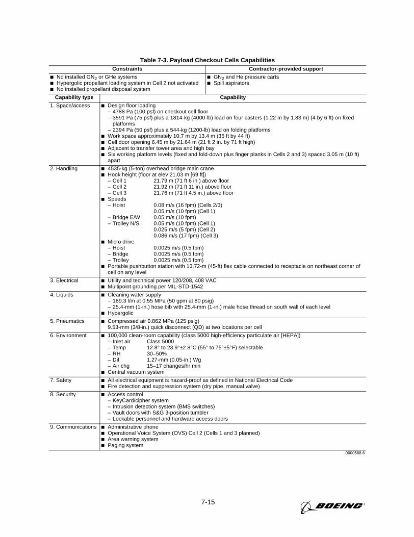
7-15
Table 7-3. Payload Checkout Cells CapabilitiesConstraints Contractor-provided support
No installed GN2 or GHe systems Hypergolic propellant loading system in Cell 2 not activated No installed propellant disposal system
GN2 and He pressure carts Spill aspirators
Capability type Capability
1. Space/access Design floor loading– 4788 Pa (100 psf) on checkout cell floor– 3591 Pa (75 psf) plus a 1814-kg (4000-lb) load on four casters (1.22 m by 1.83 m) (4 by 6 ft) on fixed
platforms– 2394 Pa (50 psf) plus a 544-kg (1200-lb) load on folding platforms
Work space approximately 10.7 m by 13.4 m (35 ft by 44 ft) Cell door opening 6.45 m by 21.64 m (21 ft 2 in. by 71 ft high) Adjacent to transfer tower area and high bay Six working platform levels (fixed and fold-down plus finger planks in Cells 2 and 3) spaced 3.05 m (10 ft)
apart
2. Handling 4535-kg (5-ton) overhead bridge main crane Hook height (floor at elev 21.03 m [69 ft])
– Cell 1 21.79 m (71 ft 6 in.) above floor– Cell 2 21.92 m (71 ft 11 in.) above floor– Cell 3 21.76 m (71 ft 4.5 in.) above floor
Speeds– Hoist 0.08 m/s (16 fpm) (Cells 2/3)
0.05 m/s (10 fpm) (Cell 1)– Bridge E/W 0.05 m/s (10 fpm)– Trolley N/S 0.05 m/s (10 fpm) (Cell 1)
0.025 m/s (5 fpm) (Cell 2)0.086 m/s (17 fpm) (Cell 3)
Micro drive– Hoist 0.0025 m/s (0.5 fpm)– Bridge 0.0025 m/s (0.5 fpm)– Trolley 0.0025 m/s (0.5 fpm)
Portable pushbutton station with 13.72-m (45-ft) flex cable connected to receptacle on northeast corner ofcell on any level
3. Electrical Utility and technical power 120/208, 408 VAC Multipoint grounding per MIL-STD-1542
4. Liquids Cleaning water supply– 189.3 l/m at 0.55 MPa (50 gpm at 80 psig)– 25.4-mm (1-in.) hose bib with 25.4-mm (1-in.) male hose thread on south wall of each level
Hypergolic
5. Pneumatics Compressed air 0.862 MPa (125 psig)9.53-mm (3/8-in.) quick disconnect (QD) at two locations per cell
6. Environment 100,000 clean-room capability (class 5000 high-efficiency particulate air [HEPA])– Inlet air Class 5000– Temp 12.8° to 23.9°±2.8°C (55° to 75°±5°F) selectable– RH 30–50%– Dif 1.27-mm (0.05-in.) Wg– Air chg 15–17 changes/hr min
Central vacuum system
7. Safety All electrical equipment is hazard-proof as defined in National Electrical Code Fire detection and suppression system (dry pipe, manual valve)
8. Security Access control– KeyCard/cipher system– Intrusion detection system (BMS switches)– Vault doors with S&G 3-position tumbler– Lockable personnel and hardware access doors
9. Communications Administrative phone Operational Voice System (OVS) Cell 2 (Cells 1 and 3 planned) Area warning system Paging system
0000568.6
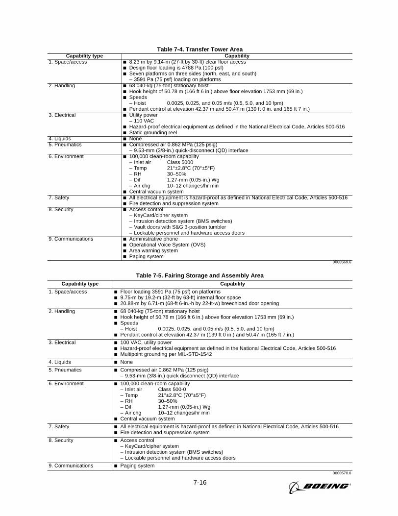
7-16
Table 7-4. Transfer Tower AreaCapability type Capability
1. Space/access 8.23 m by 9.14-m (27-ft by 30-ft) clear floor access Design floor loading is 4788 Pa (100 psf) Seven platforms on three sides (north, east, and south)
– 3591 Pa (75 psf) loading on platforms2. Handling 68 040-kg (75-ton) stationary hoist
Hook height of 50.78 m (166 ft 6 in.) above floor elevation 1753 mm (69 in.) Speeds
– Hoist 0.0025, 0.025, and 0.05 m/s (0.5, 5.0, and 10 fpm) Pendant control at elevation 42.37 m and 50.47 m (139 ft 0 in. and 165 ft 7 in.)
3. Electrical Utility power– 110 VAC
Hazard-proof electrical equipment as defined in the National Electrical Code, Articles 500-516 Static grounding reel
4. Liquids None5. Pneumatics Compressed air 0.862 MPa (125 psig)
– 9.53-mm (3/8-in.) quick-disconnect (QD) interface6. Environment 100,000 clean-room capability
– Inlet air Class 5000– Temp 21°±2.8°C (70°±5°F)– RH 30–50%– Dif 1.27-mm (0.05-in.) Wg– Air chg 10–12 changes/hr min
Central vacuum system7. Safety All electrical equipment is hazard-proof as defined in National Electrical Code, Articles 500-516
Fire detection and suppression system8. Security Access control
– KeyCard/cipher system– Intrusion detection system (BMS switches)– Vault doors with S&G 3-position tumbler– Lockable personnel and hardware access doors
9. Communications Administrative phone Operational Voice System (OVS) Area warning system Paging system
0000569.6
Table 7-5. Fairing Storage and Assembly AreaCapability type Capability
1. Space/access Floor loading 3591 Pa (75 psf) on platforms 9.75-m by 19.2-m (32-ft by 63-ft) internal floor space 20.88-m by 6.71-m (68-ft 6-in.-h by 22-ft-w) breechload door opening
2. Handling 68 040-kg (75-ton) stationary hoist Hook height of 50.78 m (166 ft 6 in.) above floor elevation 1753 mm (69 in.) Speeds
– Hoist 0.0025, 0.025, and 0.05 m/s (0.5, 5.0, and 10 fpm) Pendant control at elevation 42.37 m (139 ft 0 in.) and 50.47 m (165 ft 7 in.)
3. Electrical 100 VAC, utility power Hazard-proof electrical equipment as defined in the National Electrical Code, Articles 500-516 Multipoint grounding per MIL-STD-1542
4. Liquids None
5. Pneumatics Compressed air 0.862 MPa (125 psig)– 9.53-mm (3/8-in.) quick disconnect (QD) interface
6. Environment 100,000 clean-room capability– Inlet air Class 500-0– Temp 21°±2.8°C (70°±5°F)– RH 30–50%– Dif 1.27-mm (0.05-in.) Wg– Air chg 10–12 changes/hr min
Central vacuum system
7. Safety All electrical equipment is hazard-proof as defined in National Electrical Code, Articles 500-516 Fire detection and suppression system
8. Security Access control– KeyCard/cipher system– Intrusion detection system (BMS switches)– Lockable personnel and hardware access doors
9. Communications Paging system0000570.6
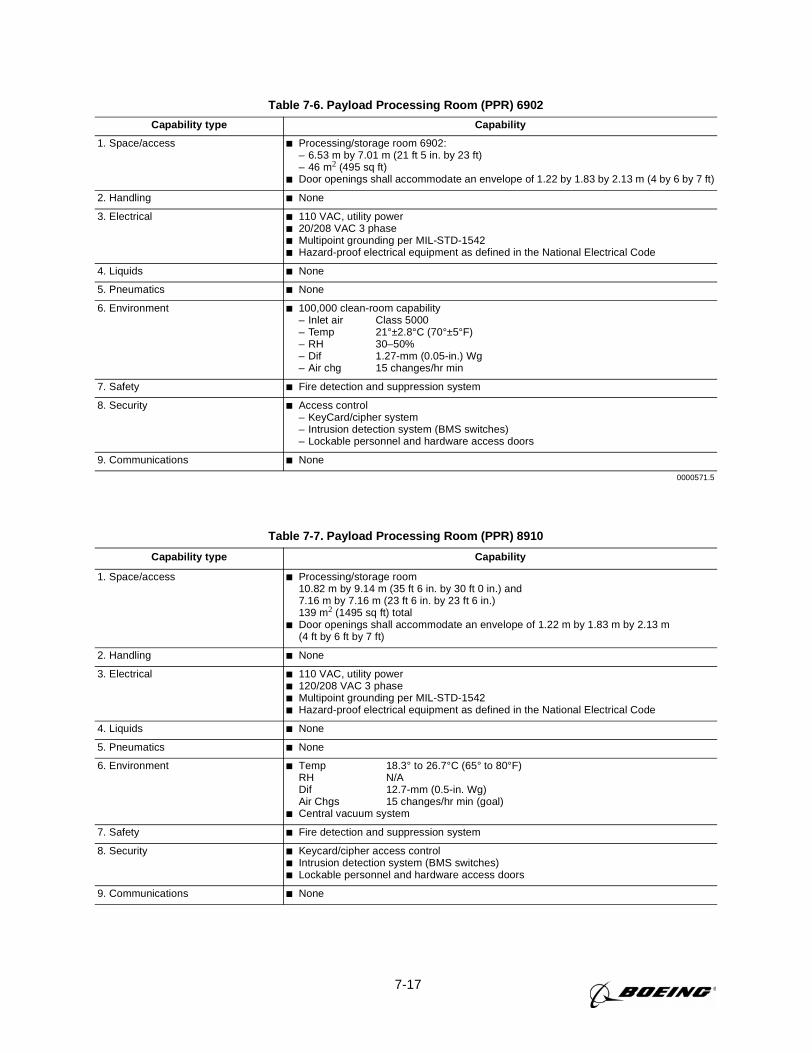
7-17
Table 7-6. Payload Processing Room (PPR) 6902
Capability type Capability
1. Space/access Processing/storage room 6902:– 6.53 m by 7.01 m (21 ft 5 in. by 23 ft)– 46 m2 (495 sq ft)
Door openings shall accommodate an envelope of 1.22 by 1.83 by 2.13 m (4 by 6 by 7 ft)
2. Handling None
3. Electrical 110 VAC, utility power 20/208 VAC 3 phase Multipoint grounding per MIL-STD-1542 Hazard-proof electrical equipment as defined in the National Electrical Code
4. Liquids None
5. Pneumatics None
6. Environment 100,000 clean-room capability– Inlet air Class 5000– Temp 21°±2.8°C (70°±5°F)– RH 30–50%– Dif 1.27-mm (0.05-in.) Wg– Air chg 15 changes/hr min
7. Safety Fire detection and suppression system
8. Security Access control– KeyCard/cipher system– Intrusion detection system (BMS switches)– Lockable personnel and hardware access doors
9. Communications None
0000571.5
Table 7-7. Payload Processing Room (PPR) 8910
Capability type Capability
1. Space/access Processing/storage room10.82 m by 9.14 m (35 ft 6 in. by 30 ft 0 in.) and7.16 m by 7.16 m (23 ft 6 in. by 23 ft 6 in.)139 m2 (1495 sq ft) total
Door openings shall accommodate an envelope of 1.22 m by 1.83 m by 2.13 m(4 ft by 6 ft by 7 ft)
2. Handling None
3. Electrical 110 VAC, utility power 120/208 VAC 3 phase Multipoint grounding per MIL-STD-1542 Hazard-proof electrical equipment as defined in the National Electrical Code
4. Liquids None
5. Pneumatics None
6. Environment Temp 18.3° to 26.7°C (65° to 80°F)RH N/ADif 12.7-mm (0.5-in. Wg)Air Chgs 15 changes/hr min (goal)
Central vacuum system
7. Safety Fire detection and suppression system
8. Security Keycard/cipher access control Intrusion detection system (BMS switches) Lockable personnel and hardware access doors
9. Communications None
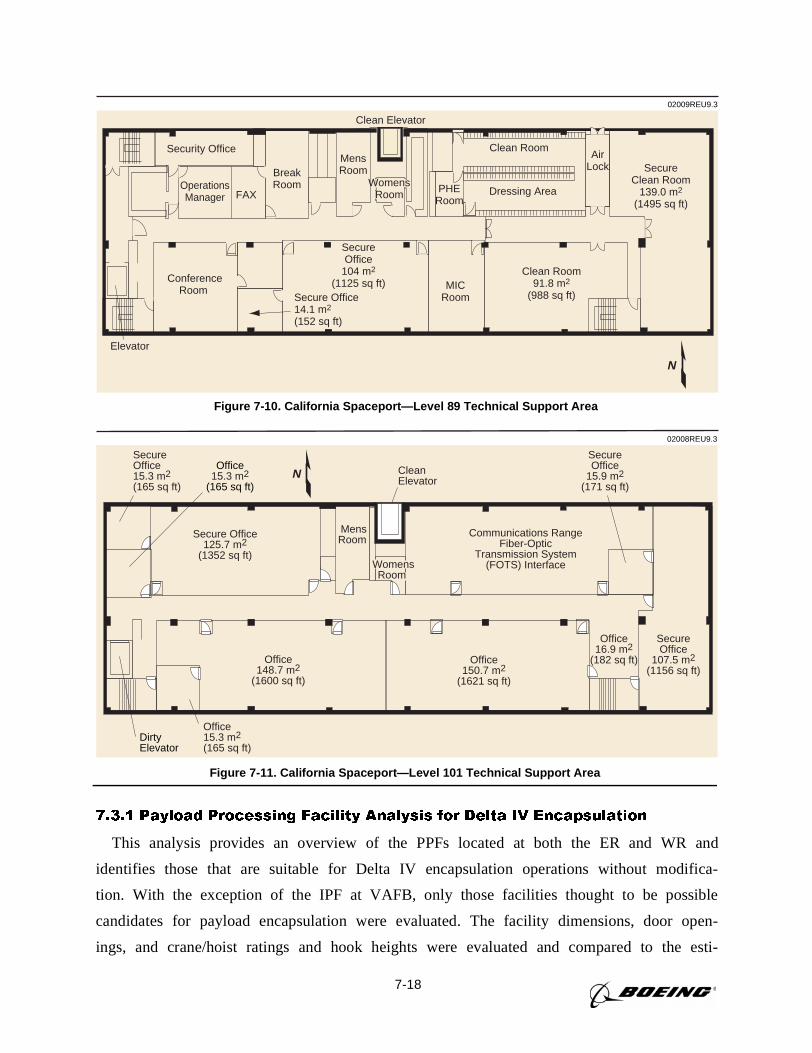
7-18
7.3.1 Payload Processing Facility Analysis for Delta IV Encapsulation
This analysis provides an overview of the PPFs located at both the ER and WR and
identifies those that are suitable for Delta IV encapsulation operations without modifica-
tion. With the exception of the IPF at VAFB, only those facilities thought to be possible
candidates for payload encapsulation were evaluated. The facility dimensions, door open-
ings, and crane/hoist ratings and hook heights were evaluated and compared to the esti-
02009REU9.3
Security Office
OperationsManager
ConferenceRoom
FAX
BreakRoom
Clean Room
Dressing Area
SecureClean Room
139.0 m2
(1495 sq ft)
MICRoom
Clean Room91.8 m2
(988 sq ft)
AirLock
SecureOffice
104 m2
(1125 sq ft)Secure Office14.1 m2
(152 sq ft)
MensRoom
PHERoom
Clean Elevator
Elevator
WomensRoom
N
Figure 7-10. California Spaceport—Level 89 Technical Support Area
02008REU9.3
SecureOffice15.3 m2(165 sq ft)
Secure Office125.7 m2
(1352 sq ft)
MensRoom
Communications RangeFiber-Optic
Transmission System(FOTS) Interface
SecureOffice
15.9 m2(171 sq ft)
SecureOffice
107.5 m2(1156 sq ft)
Office16.9 m2
(182 sq ft)Office150.7 m2
(1621 sq ft)
Office148.7 m2
(1600 sq ft)
Office15.3 m2(165 sq ft)
CleanElevator
Office15.3 m2
(165 sq ft)
DirtyElevator
WomensRoom
N
Figure 7-11. California Spaceport—Level 101 Technical Support Area
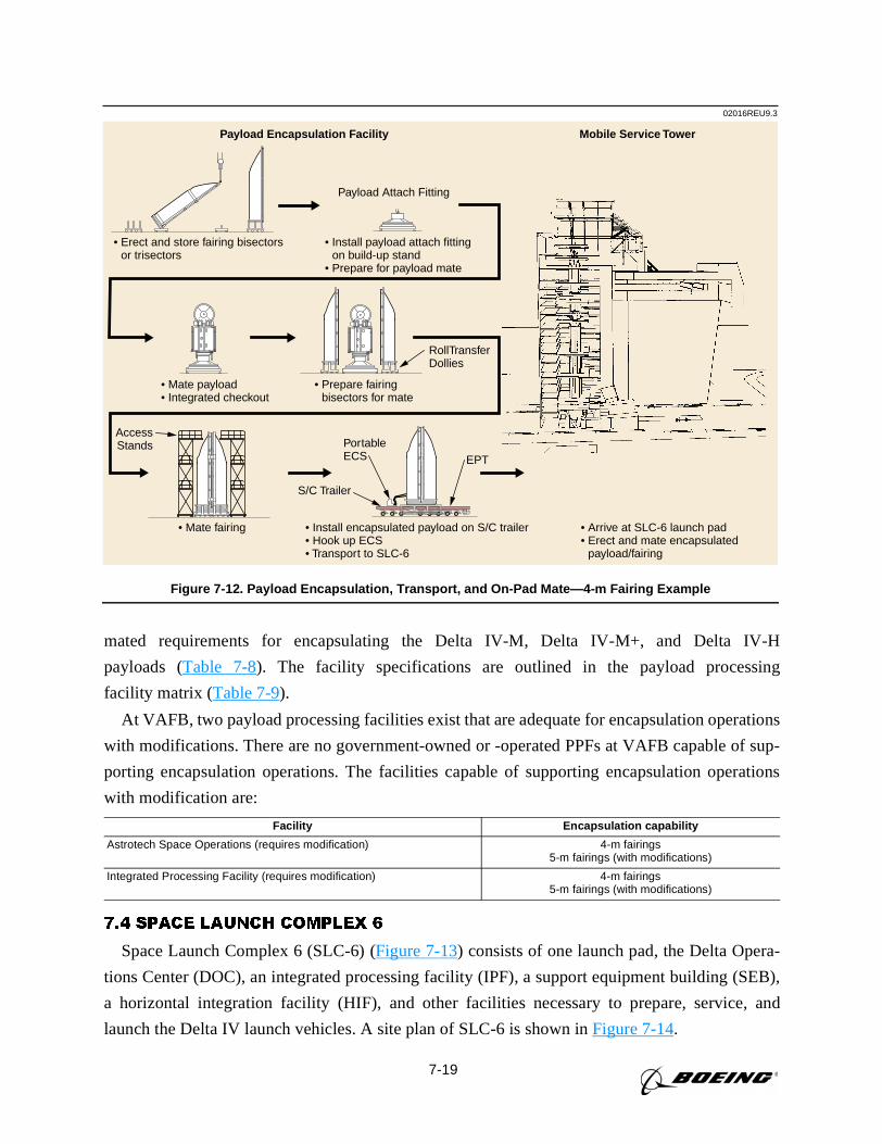
7-19
mated requirements for encapsulating the Delta IV-M, Delta IV-M+, and Delta IV-H
payloads (Table 7-8). The facility specifications are outlined in the payload processing
facility matrix (Table 7-9).
At VAFB, two payload processing facilities exist that are adequate for encapsulation operations
with modifications. There are no government-owned or -operated PPFs at VAFB capable of sup-
porting encapsulation operations. The facilities capable of supporting encapsulation operations
with modification are:
7.4 SPACE LAUNCH COMPLEX 6
Space Launch Complex 6 (SLC-6) (Figure 7-13) consists of one launch pad, the Delta Opera-
tions Center (DOC), an integrated processing facility (IPF), a support equipment building (SEB),
a horizontal integration facility (HIF), and other facilities necessary to prepare, service, and
launch the Delta IV launch vehicles. A site plan of SLC-6 is shown inFigure 7-14.
Facility Encapsulation capability
Astrotech Space Operations (requires modification) 4-m fairings5-m fairings (with modifications)
Integrated Processing Facility (requires modification) 4-m fairings5-m fairings (with modifications)
02016REU9.3
Payload Encapsulation Facility Mobile Service Tower
• Erect and store fairing bisectors or trisectors
• Install payload attach fitting on build-up stand
• Prepare for payload mate
Payload Attach Fitting
• Arrive at SLC-6 launch pad• Erect and mate encapsulated payload/fairing
• Mate fairing
AccessStands
• Prepare fairing bisectors for mate
RollTransferDollies
• Install encapsulated payload on S/C trailer• Hook up ECS• Transport to SLC-6
• Mate payload• Integrated checkout
PortableECS EPT
S/C Trailer
Figure 7-12. Payload Encapsulation, Transport, and On-Pad Mate—4-m Fairing Example
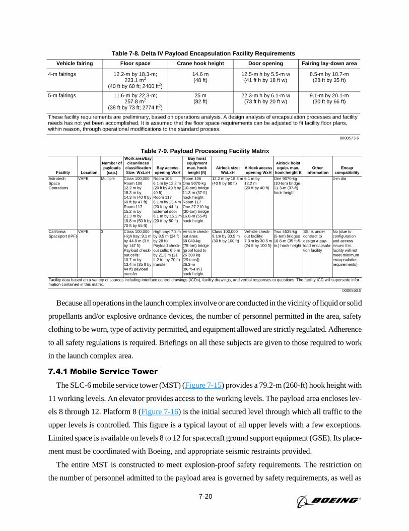
7-20
Because all operations in the launch complex involve or are conducted in the vicinity of liquid or solid
propellants and/or explosive ordnance devices, the number of personnel permitted in the area, safety
clothing to be worn, type of activity permitted, and equipment allowed are strictly regulated. Adherence
to all safety regulations is required. Briefings on all these subjects are given to those required to work
in the launch complex area.
7.4.1 Mobile Service Tower
The SLC-6 mobile service tower (MST) (Figure 7-15) provides a 79.2-m (260-ft) hook height with
11 working levels. An elevator provides access to the working levels. The payload area encloses lev-
els 8 through 12. Platform 8 (Figure 7-16) is the initial secured level through which all traffic to the
upper levels is controlled. This figure is a typical layout of all upper levels with a few exceptions.
Limited space is available on levels 8 to 12 for spacecraft ground support equipment (GSE). Its place-
ment must be coordinated with Boeing, and appropriate seismic restraints provided.
The entire MST is constructed to meet explosion-proof safety requirements. The restriction on
the number of personnel admitted to the payload area is governed by safety requirements, as well as
Table 7-8. Delta IV Payload Encapsulation Facility Requirements
Vehicle fairing Floor space Crane hook height Door opening Fairing lay -down area
4-m fairings 12.2-m by 18.3-m;223.1 m2
(40 ft by 60 ft; 2400 ft2)
14.6 m(48 ft)
12.5-m h by 5.5-m w(41 ft h by 18 ft w)
8.5-m by 10.7-m(28 ft by 35 ft)
5-m fairings 11.6-m by 22.3-m;257.8 m2
(38 ft by 73 ft; 2774 ft2)
25 m(82 ft)
22.3-m h by 6.1-m w(73 ft h by 20 ft w)
9.1-m by 20.1-m(30 ft by 66 ft)
These facility requirements are preliminary, based on operations analysis. A design analysis of encapsulation processes and facilityneeds has not yet been accomplished. It is assumed that the floor space requirements can be adjusted to fit facility floor plans,within reason, through operational modifications to the standard process.
0000573.6
Table 7-9. Payload Processing Facility Matrix
Facility Location
Number ofpayloads
(cap.)
Work area/baycleanliness
classificationSize: WxLxH
Bay accessopening WxH
Bay hoistequipmentmax. hookheight (ft)
Airlock size:WxLxH
Airlock accessopening WxH
Airlock hoistequip. max.
hook height ftOther
informationEncap
compatibility
AstrotechSpaceOperations
VAFB Multiple Class 100,000Room 10612.2 m by18.3 m by14.3 m (40 ft by60 ft by 47 ft)Room 11715.2 m by21.3 m by19.8 m (50 ft by70 ft by 65 ft)
Room 1066.1 m by 12.2 m(20 ft by 40 ft by40 ft)Room 1176.1 m by 13.4 m(20 ft by 44 ft)External door6.1 m by 15.2 m(20 ft by 50 ft)
Room 106One 9070-kg(10-ton) bridge11.3-m (37-ft)hook heightRoom 117One 27 210-kg(30-ton) bridge16.8-m (55-ft)hook height
12.2 m by 18.3 m(40 ft by 60 ft)
6.1 m by12.2 m(20 ft by 40 ft)
One 9070-kg(10-ton) bridge11.3-m (37-ft)hook height
4-m dia
CaliforniaSpaceport (IPF)
VAFB 3 Class 100,000High bay: 9.1 mby 44.8 m (3 ftby 147 ft)Payload check-out cells:10.7 m by13.4 m (35 ft by44 ft) payloadtransfer
High bay: 7.3 mby 8.5 m (24 ftby 28 ft)Payload check-out cells: 6.5 mby 21.3 m (21ft-2 in. by 70 ft)transfer
Vehicle check-out area:68 040-kg(75-ton) bridge(proof load to26 300 kg[29 tons])26.3-m(86 ft-4 in.)hook height
Class 100,0009.1m by 30.5 m(30 ft by 100 ft)
Vehicle check-out facility:7.3 m by 30.5 m(24 ft by 100 ft)
Two 4535-kg(5-ton) bridges10.8-m (35 ft-5-in.) hook height
SSI is undercontract todesign a pay-load encapsula-tion facility
No (due toconfigurationand accessissues thisfacility will notmeet minimumencapsulationrequirements)
Facility data based on a variety of sources including interface control drawings (ICDs), facility drawings, and verbal responses to questions. The facility ICD will supersede infor-mation contained in this matrix.
0000560.8
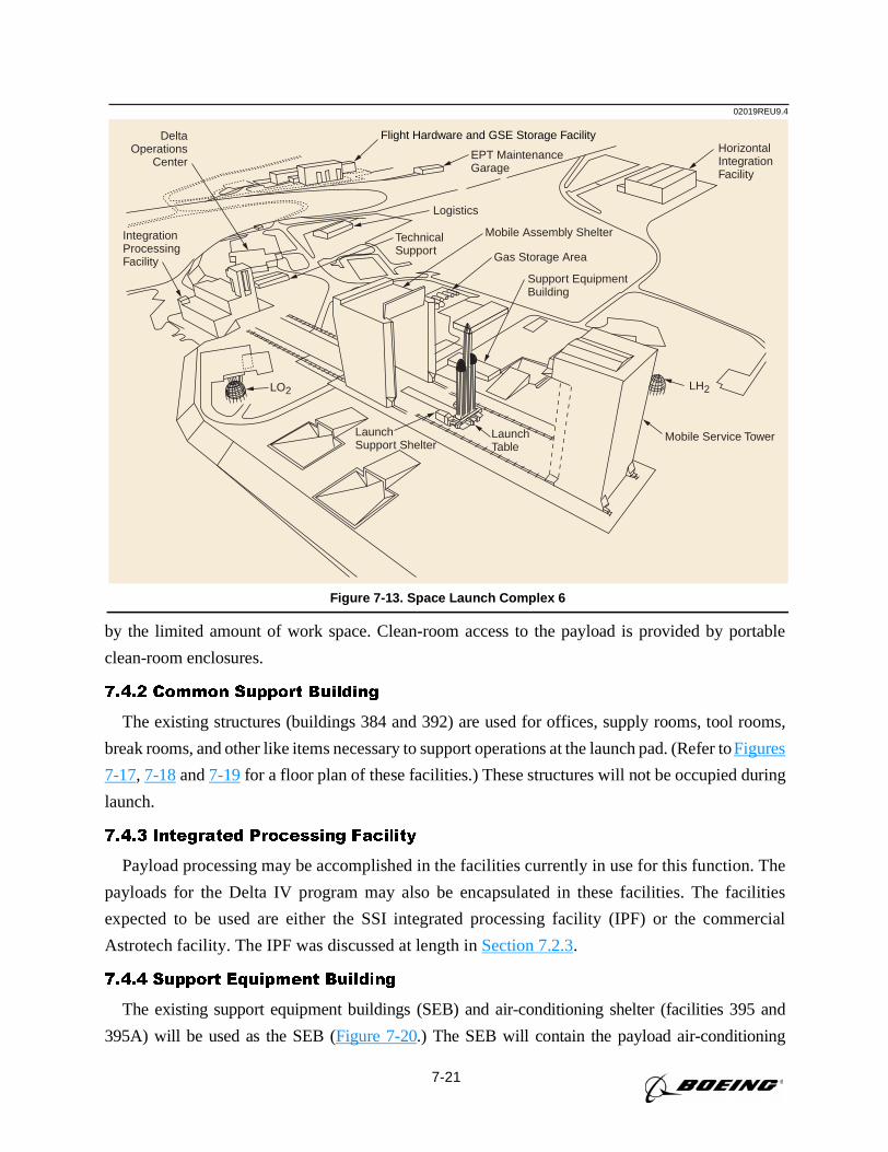
7-21
by the limited amount of work space. Clean-room access to the payload is provided by portable
clean-room enclosures.
7.4.2 Common Support Building
The existing structures (buildings 384 and 392) are used for offices, supply rooms, tool rooms,
break rooms, and other like items necessary to support operations at the launch pad. (Refer toFigures
7-17, 7-18and7-19for a floor plan of these facilities.) These structures will not be occupied during
launch.
7.4.3 Integrated Processing Facility
Payload processing may be accomplished in the facilities currently in use for this function. The
payloads for the Delta IV program may also be encapsulated in these facilities. The facilities
expected to be used are either the SSI integrated processing facility (IPF) or the commercial
Astrotech facility. The IPF was discussed at length inSection 7.2.3.
7.4.4 Support Equipment Building
The existing support equipment buildings (SEB) and air-conditioning shelter (facilities 395 and
395A) will be used as the SEB (Figure 7-20.) The SEB will contain the payload air-conditioning
02019REU9.4
Flight Hardware and GSE Storage Facility
TechnicalSupport
EPT MaintenanceGarage
Logistics
Mobile Assembly Shelter
Gas Storage Area
Support EquipmentBuilding
HorizontalIntegrationFacility
Mobile Service Tower
LH2LO2
LaunchTable
LaunchSupport Shelter
IntegrationProcessingFacility
DeltaOperations
Center
Figure 7-13. Space Launch Complex 6
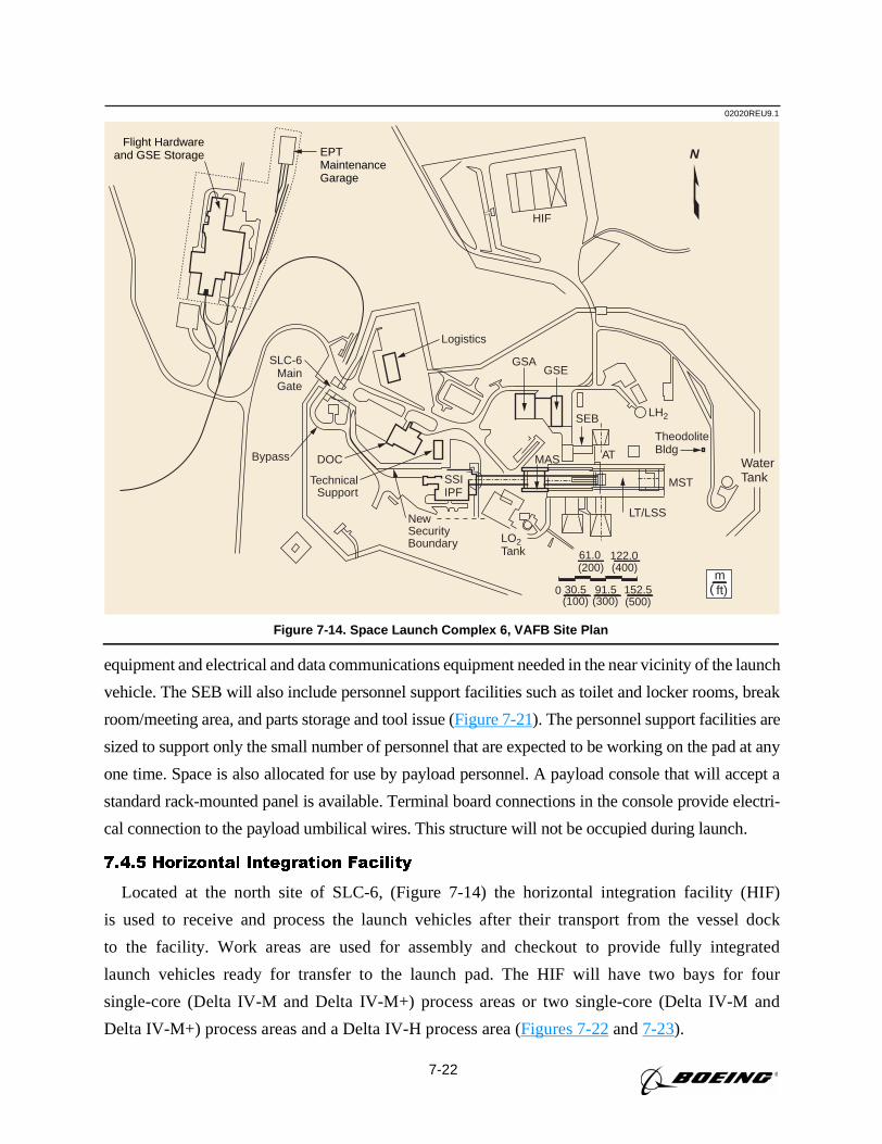
7-22
equipment and electrical and data communications equipment needed in the near vicinity of the launch
vehicle. The SEB will also include personnel support facilities such as toilet and locker rooms, break
room/meeting area, and parts storage and tool issue (Figure 7-21). The personnel support facilities are
sized to support only the small number of personnel that are expected to be working on the pad at any
one time. Space is also allocated for use by payload personnel. A payload console that will accept a
standard rack-mounted panel is available. Terminal board connections in the console provide electri-
cal connection to the payload umbilical wires. This structure will not be occupied during launch.
7.4.5 Horizontal Integration Facility
Located at the north site of SLC-6, (Figure 7-14) the horizontal integration facility (HIF)
is used to receive and process the launch vehicles after their transport from the vessel dock
to the facility. Work areas are used for assembly and checkout to provide fully integrated
launch vehicles ready for transfer to the launch pad. The HIF will have two bays for four
single-core (Delta IV-M and Delta IV-M+) process areas or two single-core (Delta IV-M and
Delta IV-M+) process areas and a Delta IV-H process area (Figures 7-22and7-23).
Flight Hardwareand GSE Storage EPT
MaintenanceGarage
Bypass
SLC-6MainGate
TechnicalSupport
NewSecurityBoundary
SSIIPF
DOC
GSAGSE
Logistics
TheodoliteBldg
MST
WaterTank
LH2
LO2Tank
SEB
ATMAS
LT/LSS
HIF
(100) (300) (500)0 30.5 91.5 152.5
(200) (400)61.0 122.0
ft)m
(
N
02020REU9.1
Figure 7-14. Space Launch Complex 6, VAFB Site Plan
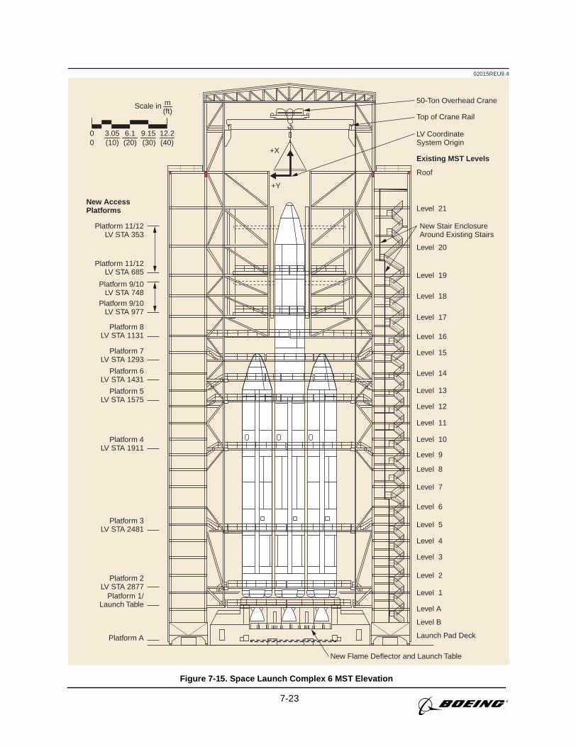
7-23
Scale in
0 (10) (20) (30) (40)0 3.05 6.1 9.15 12.2
m(ft)
02015REU9.4
Platform 11/12LV STA 353
New AccessPlatforms
Platform 11/12LV STA 685
Platform 9/10LV STA 748
Platform 9/10LV STA 977
Platform 8LV STA 1131
Platform 7LV STA 1293
Platform 6LV STA 1431
Platform 5LV STA 1575
Platform 4LV STA 1911
Platform 3LV STA 2481
Platform 2LV STA 2877
Platform A
Platform 1/Launch Table
New Flame Deflector and Launch Table
Launch Pad Deck
Level B
Level A
Level 1
Level 2
Level 3
Level 4
Level 5
Level 6
Level 7
Level 8
Level 9
Level 10
Level 11
Level 12
Level 13
Level 14
Level 15
Level 16
Level 17
Level 18
Level 19
Level 20
Level 21
Roof
Top of Crane Rail
Existing MST Levels
LV CoordinateSystem Origin
New Stair EnclosureAround Existing Stairs
50-Ton Overhead Crane
+X
+Y
Figure 7-15. Space Launch Complex 6 MST Elevation
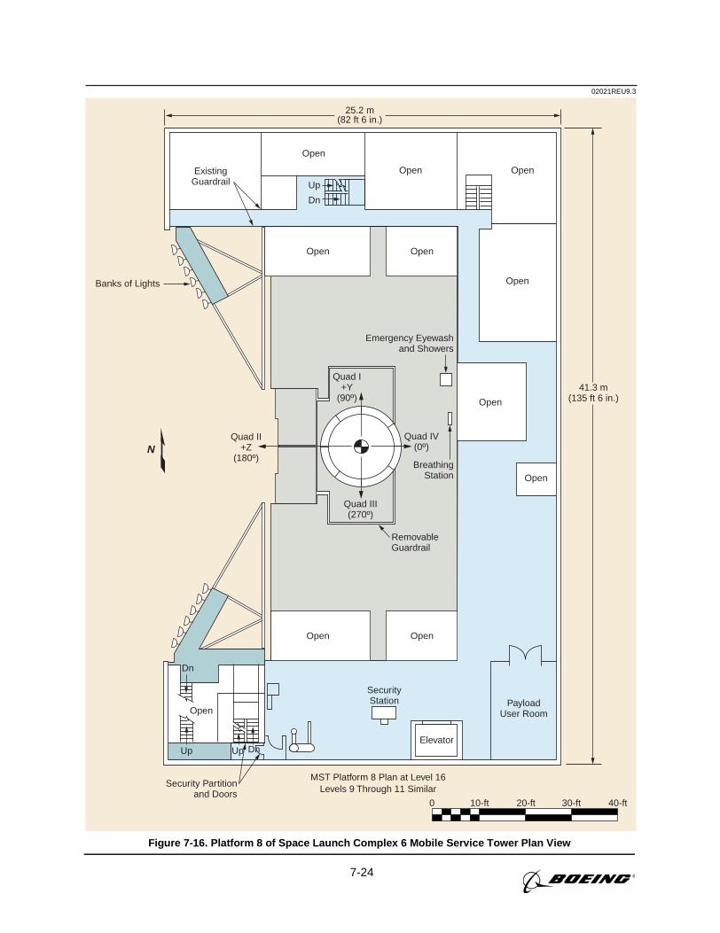
7-24
02021REU9.3
25.2 m(82 ft 6 in.)
ExistingGuardrail
Banks of Lights
Quad I+Y
(90º)
Quad II+Z
(180º)
Quad III(270º)
Quad IV(0º)
Security Partitionand Doors
Elevator
PayloadUser Room
MST Platform 8 Plan at Level 16Levels 9 Through 11 Similar
0 10-ft 20-ft 30-ft 40-ft
SecurityStation
Open
Up Up Dn
Dn
RemovableGuardrail
Dn
Open
Open Open
OpenOpen
OpenOpen
Open
Open
Emergency Eyewashand Showers
BreathingStation Open
Up
41.3 m(135 ft 6 in.)
N
Figure 7-16. Platform 8 of Space Launch Complex 6 Mobile Service Tower Plan View
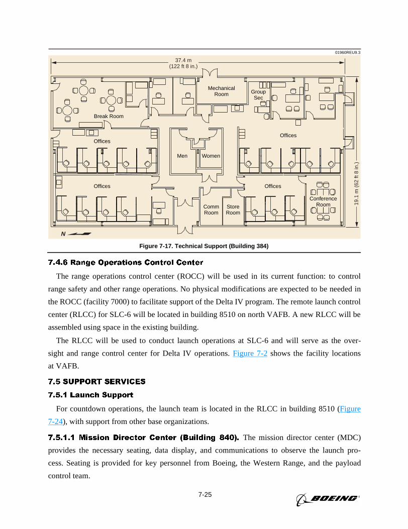
7-25
7.4.6 Range Operations Control Center
The range operations control center (ROCC) will be used in its current function: to control
range safety and other range operations. No physical modifications are expected to be needed in
the ROCC (facility 7000) to facilitate support of the Delta IV program. The remote launch control
center (RLCC) for SLC-6 will be located in building 8510 on north VAFB. A new RLCC will be
assembled using space in the existing building.
The RLCC will be used to conduct launch operations at SLC-6 and will serve as the over-
sight and range control center for Delta IV operations.Figure 7-2shows the facility locations
at VAFB.
7.5 SUPPORT SERVICES
7.5.1 Launch Support
For countdown operations, the launch team is located in the RLCC in building 8510 (Figure
7-24), with support from other base organizations.
7.5.1.1 Mission Director Center (Building 840). The mission director center (MDC)
provides the necessary seating, data display, and communications to observe the launch pro-
cess. Seating is provided for key personnel from Boeing, the Western Range, and the payload
control team.
MechanicalRoom Group
Sec
CommRoom
StoreRoom
Men
Offices
Offices
Offices
Offices
Break Room
Women
N
ConferenceRoom
01960REU9.3
37.4 m(122 ft 8 in.)
19.1
m (
62 ft
8 in
.)
Figure 7-17. Technical Support (Building 384)
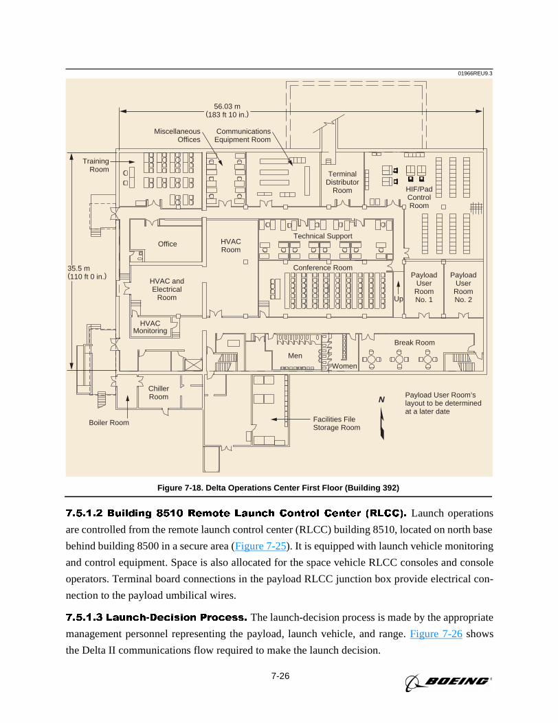
7-26
7.5.1.2 Building 8510 Remote Launch Control Center (RLCC). Launch operations
are controlled from the remote launch control center (RLCC) building 8510, located on north base
behind building 8500 in a secure area (Figure 7-25). It is equipped with launch vehicle monitoring
and control equipment. Space is also allocated for the space vehicle RLCC consoles and console
operators. Terminal board connections in the payload RLCC junction box provide electrical con-
nection to the payload umbilical wires.
7.5.1.3 Launch-Decision Process. The launch-decision process is made by the appropriate
management personnel representing the payload, launch vehicle, and range.Figure 7-26shows
the Delta II communications flow required to make the launch decision.
Facilities FileStorage Room
Payload User Room’slayout to be determinedat a later date
Boiler Room
Office HVACRoom
TrainingRoom
MiscellaneousOffices
CommunicationsEquipment Room
PayloadUser
RoomNo. 1
TerminalDistributor
Room HIF/PadControlRoom
PayloadUser
RoomNo. 2
ChillerRoom
Men
Break Room
Up
Women
HVACMonitoring
HVAC andElectrical
Room
Technical Support
Conference Room
N
01966REU9.3
56.03 m(183 ft 10 in.)
35.5 m(110 ft 0 in.)
Figure 7-18. Delta Operations Center First Floor (Building 392)
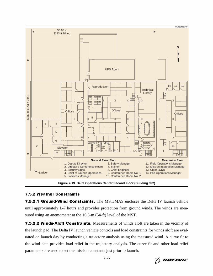
7-27
7.5.2 Weather Constraints
7.5.2.1 Ground-Wind Constraints. The MST/MAS encloses the Delta IV launch vehicle
until approximately L-7 hours and provides protection from ground winds. The winds are mea-
sured using an anemometer at the 16.5-m (54-ft) level of the MST.
7.5.2.2 Winds-Aloft Constraints. Measurements of winds aloft are taken in the vicinity of
the launch pad. The Delta IV launch vehicle controls and load constraints for winds aloft are eval-
uated on launch day by conducting a trajectory analysis using the measured wind. A curve fit to
the wind data provides load relief in the trajectory analysis. The curve fit and other load-relief
parameters are used to set the mission constants just prior to launch.
UPS Room
1
2
3 4
5
6
Elevator
Ladder
9
8
14
11
13 12
10
7
TechnicalLibrary
Reproduction
Women Men
43.8
2 m
(14
3 ft
9 in
.)
N
1. Deputy Director2. Director’s Conference Room3. Security Spec4. Chief of Launch Operations5. Business Manager
6. Safety Manager 7. Trainer 8. Chief Engineer 9. Conference Room No. 110. Conference Room No. 2
11. Field Operations Manager12. Mission Integration Manager13. Chief LCDR14. Pad Operations Manager
Second Floor Plan Mezzanine Plan
01969REU9.4
Offices OfficesOffices
56.03 m(183 ft 10 in.)
Figure 7-19. Delta Operations Center Second Floor (Building 392)
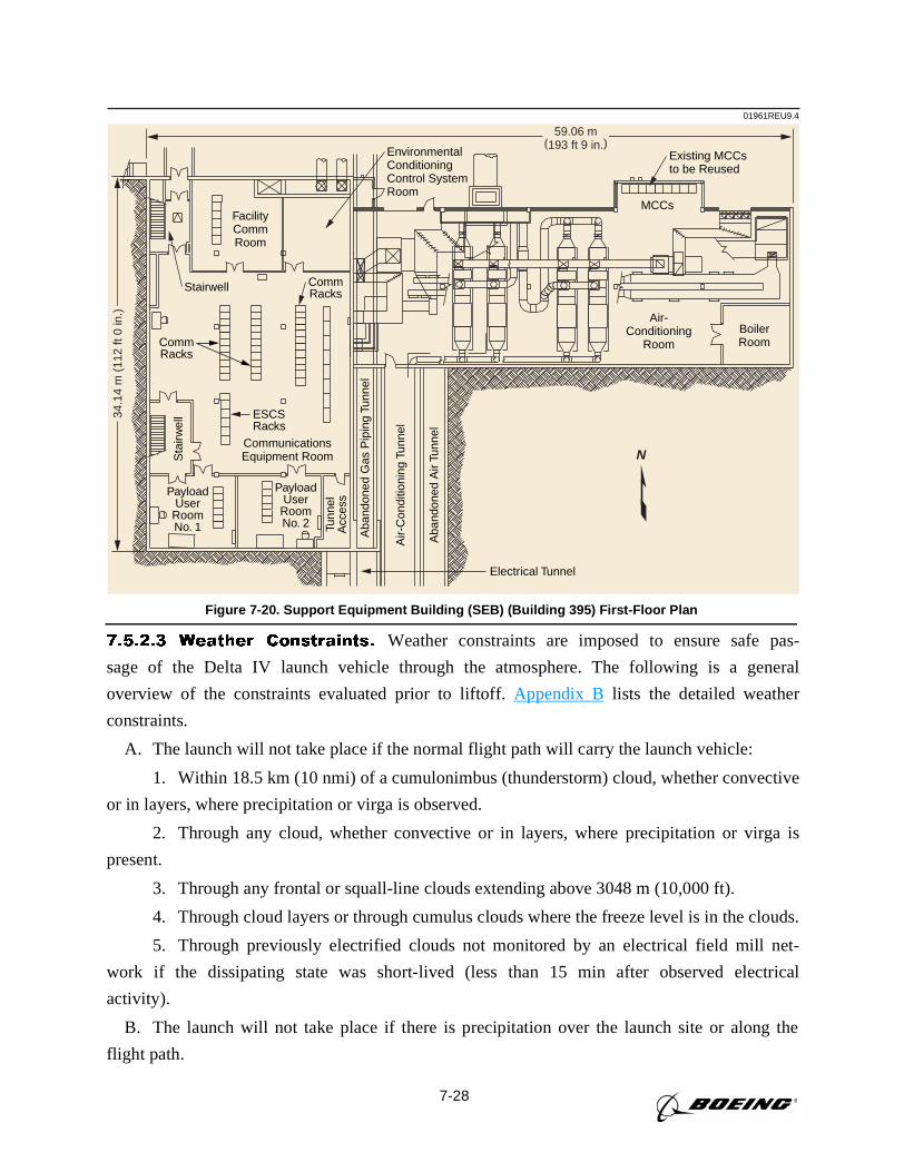
7-28
7.5.2.3 Weather Constraints. Weather constraints are imposed to ensure safe pas-
sage of the Delta IV launch vehicle through the atmosphere. The following is a general
overview of the constraints evaluated prior to liftoff.Appendix B lists the detailed weather
constraints.
A. The launch will not take place if the normal flight path will carry the launch vehicle:
1. Within 18.5 km (10 nmi) of a cumulonimbus (thunderstorm) cloud, whether convective
or in layers, where precipitation or virga is observed.
2. Through any cloud, whether convective or in layers, where precipitation or virga is
present.
3. Through any frontal or squall-line clouds extending above 3048 m (10,000 ft).
4. Through cloud layers or through cumulus clouds where the freeze level is in the clouds.
5. Through previously electrified clouds not monitored by an electrical field mill net-
work if the dissipating state was short-lived (less than 15 min after observed electrical
activity).
B. The launch will not take place if there is precipitation over the launch site or along the
flight path.
EnvironmentalConditioningControl SystemRoom
FacilityCommRoom
CommunicationsEquipment Room
CommRacks
CommRacks
ESCSRacks
Electrical Tunnel
Air-Conditioning
RoomBoilerRoom
MCCs
Existing MCCsto be Reused
PayloadUser
RoomNo. 1
PayloadUser
RoomNo. 2
Air-
Con
ditio
ning
Tun
nel
Aba
ndon
ed A
ir Tu
nnel
Aba
ndon
ed G
as P
ipin
g Tu
nnel
Tunn
elA
cces
s
Sta
irwel
l
Stairwell
N
01961REU9.434
.14
m (
112
ft 0
in.)
59.06 m(193 ft 9 in.)
Figure 7-20. Support Equipment Building (SEB) (Building 395) First-Floor Plan
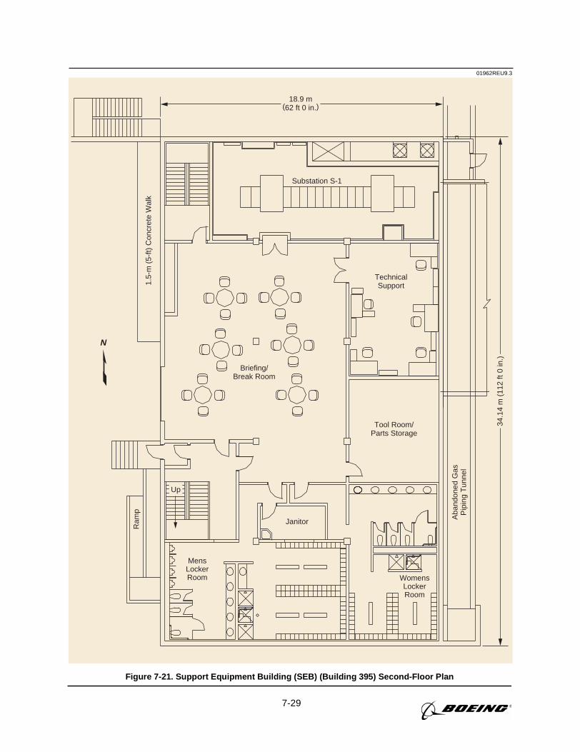
7-29
1.5-
m (
5-ft)
Con
cret
e W
alk
Briefing/Break Room
Tool Room/Parts Storage
MensLockerRoom Womens
LockerRoom
Janitor Aba
ndon
ed G
asP
ipin
g T
unne
l
TechnicalSupport
Substation S-1
Ram
p
01962REU9.3
N
Up34
.14
m (
112
ft 0
in.)
18.9 m(62 ft 0 in.)
Figure 7-21. Support Equipment Building (SEB) (Building 395) Second-Floor Plan
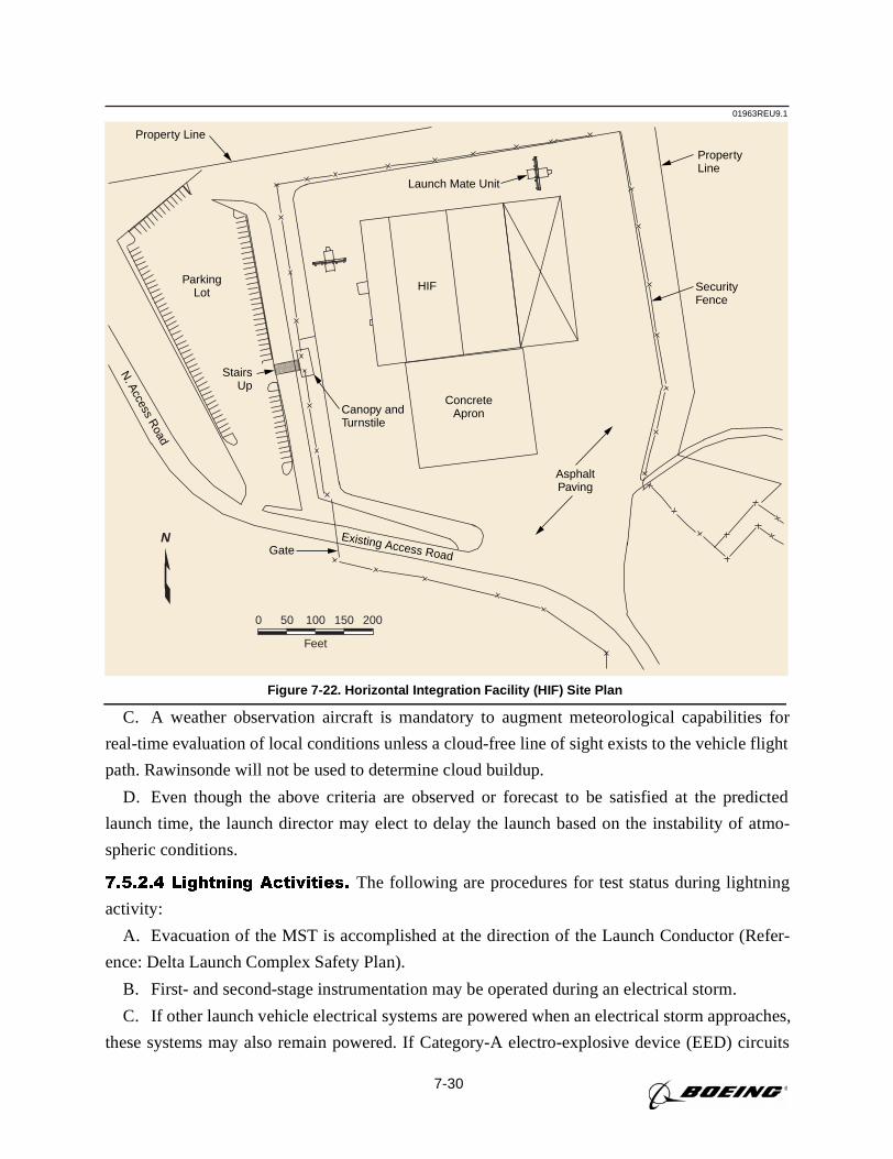
7-30
C. A weather observation aircraft is mandatory to augment meteorological capabilities for
real-time evaluation of local conditions unless a cloud-free line of sight exists to the vehicle flight
path. Rawinsonde will not be used to determine cloud buildup.
D. Even though the above criteria are observed or forecast to be satisfied at the predicted
launch time, the launch director may elect to delay the launch based on the instability of atmo-
spheric conditions.
7.5.2.4 Lightning Activities. The following are procedures for test status during lightning
activity:
A. Evacuation of the MST is accomplished at the direction of the Launch Conductor (Refer-
ence: Delta Launch Complex Safety Plan).
B. First- and second-stage instrumentation may be operated during an electrical storm.
C. If other launch vehicle electrical systems are powered when an electrical storm approaches,
these systems may also remain powered. If Category-A electro-explosive device (EED) circuits
SecurityFence
PropertyLine
HIF
ConcreteApronCanopy and
Turnstile
Gate
StairsUp
Launch Mate Unit
ParkingLot
AsphaltPaving
Property Line
N. A
ccess Road
Existing Access Road
0 50 100 150
Feet
200
N
01963REU9.1
Figure 7-22. Horizontal Integration Facility (HIF) Site Plan
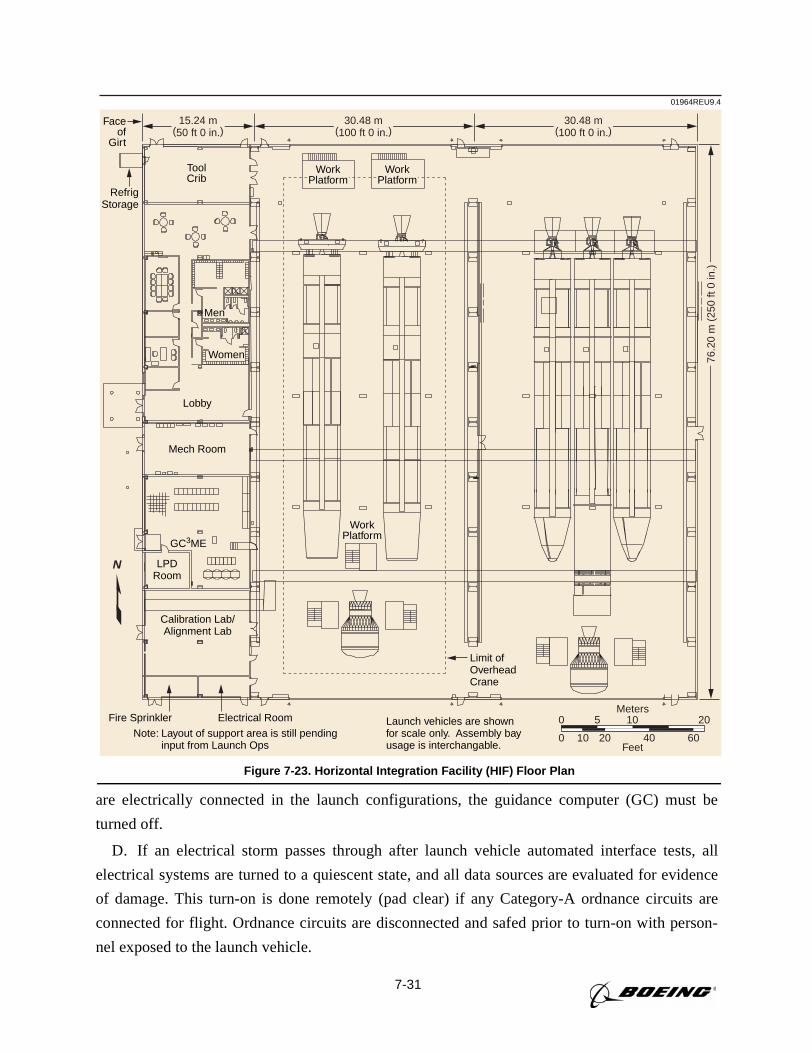
7-31
are electrically connected in the launch configurations, the guidance computer (GC) must be
turned off.
D. If an electrical storm passes through after launch vehicle automated interface tests, all
electrical systems are turned to a quiescent state, and all data sources are evaluated for evidence
of damage. This turn-on is done remotely (pad clear) if any Category-A ordnance circuits are
connected for flight. Ordnance circuits are disconnected and safed prior to turn-on with person-
nel exposed to the launch vehicle.
ToolCrib
Faceof
Girt
RefrigStorage
Men
Women
Lobby
WorkPlatform
Mech Room
Calibration Lab/Alignment Lab
LPDRoom
GC3ME
Note: Layout of support area is still pendingNote: input from Launch Ops
Launch vehicles are shownfor scale only. Assembly bayusage is interchangable.
Limit ofOverheadCrane
Fire Sprinkler Electrical Room
WorkPlatform
WorkPlatform
0
0 5
20
20
10
10
40 60Feet
Meters
N
01964REU9.4
76.2
0 m
(25
0 ft
0 in
.)
30.48 m(100 ft 0 in.)
30.48 m(100 ft 0 in.)
15.24 m(50 ft 0 in.)
Figure 7-23. Horizontal Integration Facility (HIF) Floor Plan
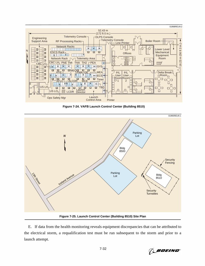
7-32
E. If data from the health monitoring reveals equipment discrepancies that can be attributed to
the electrical storm, a requalification test must be run subsequent to the storm and prior to a
launch attempt.
01968REU9.2
Telemetry Area
Network Racks
ESCS Rack
Network Rack
RF Processing Racks
Offices
Boiler Room
Delta BreakRoom
P/LUser
Room1
P/LUser
Room2
Lower LevelMechanicalEquipment
Room
LaunchControl Area
CBC LO2CBC LH2
US LO2
ALCDRAFLC
LCDR
Timer
Printer
TBDLaunchDirector
MCE
THAPNE TMI TH2 PEASYS
US LH2
HYEMEQ
FMA GE MEAECS
Telemetry ConsoleEngineeringSupport Area Telemetry Console
Line Printer
DLPS Console
Ops Safety Mgr
52.43 m(172 ft 0 in.)
N
16.2
3 m
(56
ft 3
in.)
Figure 7-24. VAFB Launch Control Center (Building 8510)
01965REU9.1
SecurityFencing
SecurityTurnstiles
13th Street Iceland Avenue
Bldg8500
Bldg8510
ParkingLot
ParkingLot
N
Figure 7-25. Launch Control Center (Building 8510) Site Plan
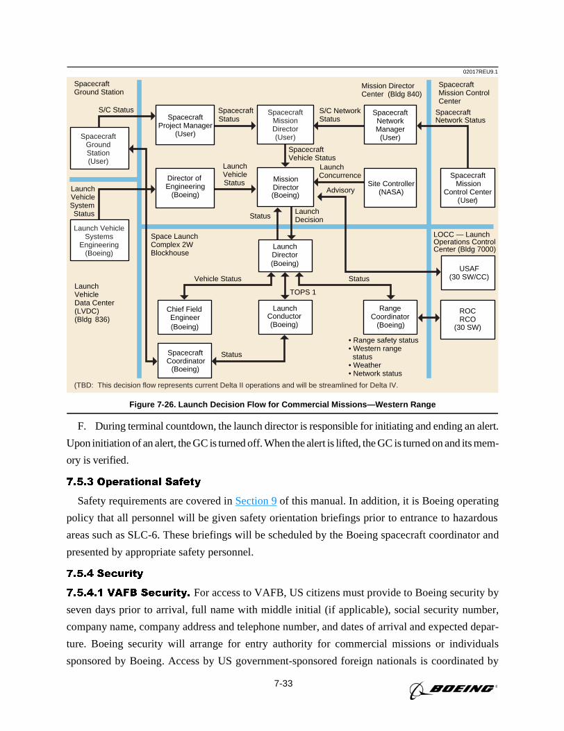
7-33
F. During terminal countdown, the launch director is responsible for initiating and ending an alert.
Upon initiation of an alert, the GC is turned off. When the alert is lifted, the GC is turned on and its mem-
ory is verified.
7.5.3 Operational Safety
Safety requirements are covered inSection 9of this manual. In addition, it is Boeing operating
policy that all personnel will be given safety orientation briefings prior to entrance to hazardous
areas such as SLC-6. These briefings will be scheduled by the Boeing spacecraft coordinator and
presented by appropriate safety personnel.
7.5.4 Security
7.5.4.1 VAFB Security. For access to VAFB, US citizens must provide to Boeing security by
seven days prior to arrival, full name with middle initial (if applicable), social security number,
company name, company address and telephone number, and dates of arrival and expected depar-
ture. Boeing security will arrange for entry authority for commercial missions or individuals
sponsored by Boeing. Access by US government-sponsored foreign nationals is coordinated by
02017REU9.1
Launch VehicleStatus
Status
MissionDirector
SpacecraftVehicle Status
LaunchConcurrence
LaunchDecisionStatus
Chief FieldEngineer
Vehicle Status
RangeCoordinator
LaunchConductor
LaunchDirector
• Range safety status• Western range status• Weather• Network status
LOCC — Launch Operations Control Center (Bldg 7000)
StatusLaunchVehicleData Center(LVDC)(Bldg 836)
Mission Director Center (Bldg 840)
LaunchVehicleSystemStatus
SpacecraftMission ControlCenter
SpacecraftNetwork Status
TOPS 1
S/C NetworkStatus
S/C Status
Advisory
USAF(30 SW/CC)
CoordinatorStatus
Space LaunchComplex 2WBlockhouse
(Boeing)
(Boeing)
(Boeing) (Boeing)(Boeing)
(Boeing)
(TBD: This decision flow represents current Delta II operations and will be streamlined for Delta IV.
Spacecraft
Spacecraft
SpacecraftGround Station
Project Manager(User)
Spacecraft
Director of Engineering
(Boeing)
ROCRCO
(30 SW)
(User
Spacecraft Mission
Control Center)
SpacecraftNetworkManager
(User)
Site Controller(NASA)
SpacecraftMissionDirector(User)Spacecraft
GroundStation(User)
Launch VehicleSystems
Engineering(Boeing)
Figure 7-26. Launch Decision Flow for Commercial Missions—Western Range
7-34
their sponsor directly with the USAF at VAFB. For non-US citizens, entry authority information
(name, nationality/citizenship, date and place of birth, passport number and date/place of issue,
visa number and date of expiration, and title or job description and organization, company
address, and home address) must be furnished to Boeing security two months prior to the VAFB
entry date. Government-sponsored individuals must follow US government guidelines as appro-
priate. After Boeing security obtains entry authority approval, entry to VAFB will be the same as
for US citizens.
For security requirements at facilities other than those listed below, please see the appropriate
facility user guide.
7.5.4.2 VAFB Security, Space Launch Complex 6. SLC-6 security is ensured by perim-
eter fencing, interior fencing, guards, and access badges. The MST is configured to provide secu-
rity for Priority-A resources.
Unique badging is required for unescorted entry into the fenced area at SLC-6. Arrangements
must be made through Boeing security at least 30 days prior to usage, in order to begin badging
arrangements for personnel requiring such access. Boeing personnel are also available 24 hr a day
to provide escort to others requiring access.
7.5.4.3 Hazardous Processing Facility. (TBD).
7.5.4.4 Spacecraft Processing Laboratories. Physical security at the payload process-
ing laboratories (building 836) is provided by door locks and guards. Details of the payload secu-
rity requirements are arranged through the Boeing spacecraft coordinator or appropriate payload
processing facility.
7.5.5 Field-Related Services
Boeing employs certified propellant handlers wearing propellant handler’s ensemble (PHE)
suits, equipment drivers, welders, riggers, and explosive-ordnance handlers, in addition to per-
sonnel experienced in most electrical and mechanical assembly skills such as torquing, solder-
ing, crimping, precision cleaning, and contamination control. Boeing has access to a machine
shop, metrology laboratory, LO2 cleaning facility, and proof-loading facility. Boeing opera-
tional team members are familiar with USAF, NASA, and commercial payload processing facil-
ities at VAFB and can offer all of these skills and services to the payload project during the
launch program.
7.6 DELTA IV PLANS AND SCHEDULES
7.6.1 Mission Plan
For each launch campaign, a mission plan is developed showing major tasks in a weekly timeline
format. The plan includes launch vehicle activities, prelaunch reviews, and payload PPF and HIF
occupancy times.
7-35
7.6.2 Integrated Schedules
The schedule of payload activities occurring before integrated activities in the HIF varies from
mission to mission. The extent of payload field testing varies and is determined by the payload
contractor.
Payload/launch vehicle schedules are similar from mission to mission from the time of payload
weighing until launch.
Daily schedules are prepared on hourly timelines for these integrated activities. Daily schedules
will typically cover the encapsulation effort in the PPF and all days-of-launch countdown activi-
ties. PPF tasks include payload weighing, if required, spacecraft-to-PAF mate and interface verifi-
cation, and fairing encapsulation around the combined payload.Figures 7-27, 7-28, 7-29, 7-30, 7-
31, and7-32 show the processing time lines for Delta IV-M, Delta IV-M+ (4,2), Delta IV-M+
(5,2), Delta IV-M+ (5,4), Delta IV-H and Delta IV-H dual manifest, respectively.
The countdown schedules provide detailed hour-by-hour breakdowns of launch pad operations,
illustrating the flow of activities from payload erection through terminal countdown, and reflecting
inputs from the spacecraft contractor. These schedules comprise the integrating document to ensure
timely launch pad operations.
The integrated processing time lines do not normally include Saturdays, Sundays, or holidays.
The schedules, from payload mate through launch, are coordinated with each spacecraft contractor
to optimize on-pad testing. All operations are formally conducted and controlled using launch
countdown documents. The schedule of payload activities during that time is controlled by the
Boeing launch operations manager.
7.6.3 Spacecraft Schedules
The spacecraft contractor will supply schedules to the Boeing spacecraft coordinator, who will
arrange support as required.
7.7 DELTA IV MEETINGS AND REVIEWS
During the launch scheduling preparation, various meetings and reviews occur. Some of these
will require customer input while others allow the customer to monitor the progress of the overall
mission. The Boeing mission integration manager will ensure adequate customer participation.
7.7.1 Meetings
Delta status meetings are generally held twice a week. They include a review of the activities
scheduled and accomplished since the last meeting, a discussion of problems and their solutions,
and a review of the mission schedule. Customers are encouraged to attend these meetings.
Daily schedule meetings are held to provide team members with their assignments and to sum-
marize the previous or current day’s accomplishments. These meetings are attended by the launch
conductor, technicians, inspectors, engineers, supervisors, and the spacecraft coordinator.
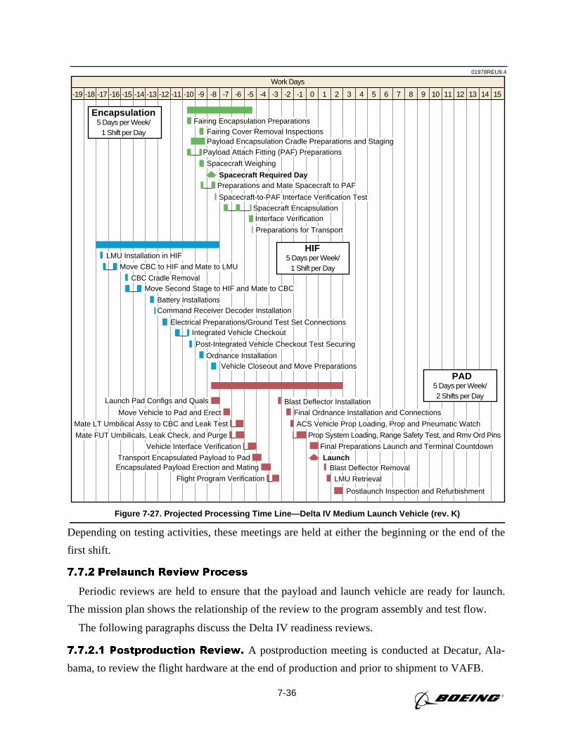
7-36
Depending on testing activities, these meetings are held at either the beginning or the end of the
first shift.
7.7.2 Prelaunch Review Process
Periodic reviews are held to ensure that the payload and launch vehicle are ready for launch.
The mission plan shows the relationship of the review to the program assembly and test flow.
The following paragraphs discuss the Delta IV readiness reviews.
7.7.2.1 Postproduction Review. A postproduction meeting is conducted at Decatur, Ala-
bama, to review the flight hardware at the end of production and prior to shipment to VAFB.
01978REU9.4
Work Days
-12-13-14-15-16-17-18-19 -11 -10 -9 -8 -7 -6 -5 -4 -3 -2 -1 0 1 2 3 4 5 7 8 9 10 11 12 13 14 156
Fairing Encapsulation PreparationsFairing Cover Removal Inspections
Spacecraft-to-PAF Interface Verification Test
Interface Verification
Payload Encapsulation Cradle Preparations and StagingPayload Attach Fitting (PAF) Preparations
Spacecraft Required DayPreparations and Mate Spacecraft to PAF
Spacecraft Encapsulation
Preparations for Transport
Spacecraft Weighing
Encapsulation5 Days per Week/
1 Shift per Day
Move CBC to HIF and Mate to LMU
CBC Cradle RemovalMove Second Stage to HIF and Mate to CBC
Battery Installations
LMU Installation in HIF
Ordnance InstallationVehicle Closeout and Move Preparations
Command Receiver Decoder Installation
Electrical Preparations/Ground Test Set ConnectionsIntegrated Vehicle Checkout
Post-Integrated Vehicle Checkout Test Securing
HIF5 Days per Week/
1 Shift per Day
Launch Pad Configs and Quals
Move Vehicle to Pad and Erect Final Ordnance Installation and Connections
Mate LT Umbilical Assy to CBC and Leak Test
Blast Deflector Installation
ACS Vehicle Prop Loading, Prop and Pneumatic Watch
Mate FUT Umbilicals, Leak Check, and Purge Prop System Loading, Range Safety Test, and Rmv Ord Pins
Vehicle Interface Verification Final Preparations Launch and Terminal Countdown
Transport Encapsulated Payload to Pad LaunchEncapsulated Payload Erection and Mating
Flight Program VerificationBlast Deflector Removal
LMU Retrieval
Postlaunch Inspection and Refurbishment
PAD5 Days per Week/2 Shifts per Day
Figure 7-27. Projected Processing Time Line—Delta IV Medium Launch Vehicle (rev. K)
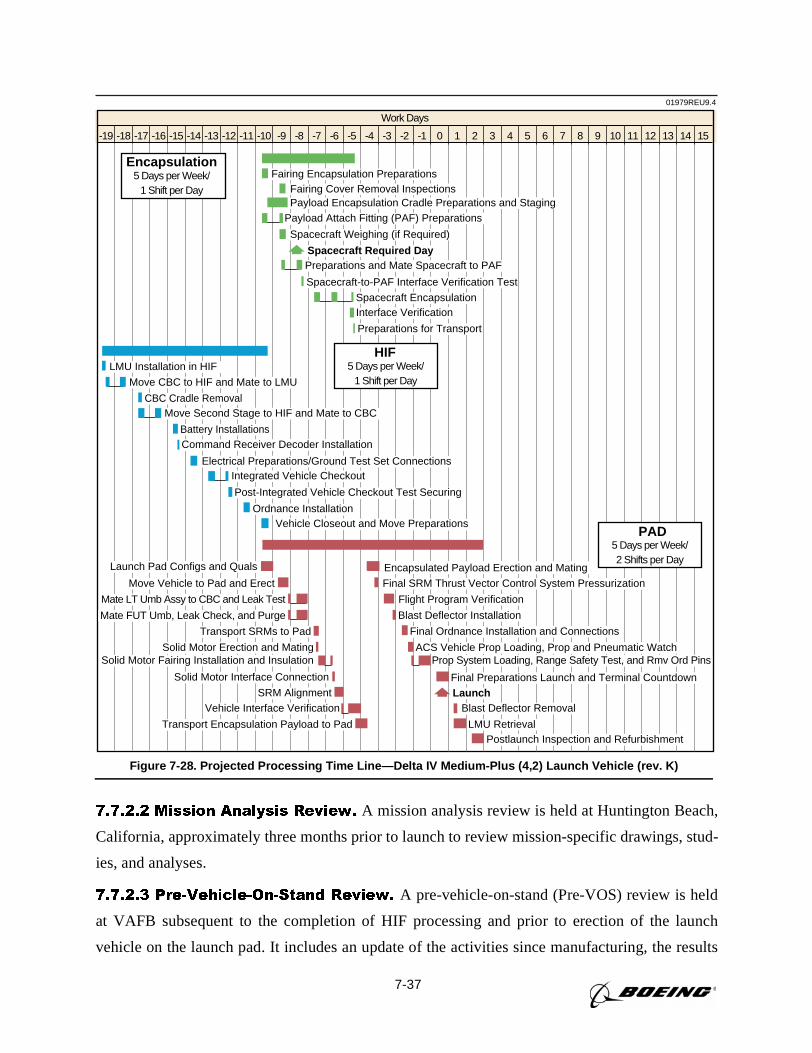
7-37
7.7.2.2 Mission Analysis Review. A mission analysis review is held at Huntington Beach,
California, approximately three months prior to launch to review mission-specific drawings, stud-
ies, and analyses.
7.7.2.3 Pre-Vehicle-On-Stand Review. A pre-vehicle-on-stand (Pre-VOS) review is held
at VAFB subsequent to the completion of HIF processing and prior to erection of the launch
vehicle on the launch pad. It includes an update of the activities since manufacturing, the results
01979REU9.4
Work Days
-12-13-14-15-16-17-18-19 -11 -10 -9 -8 -7 -6 -5 -4 -3 -2 -1 0 1 2 3 4 5 7 8 9 10 11 12 13 14 156
Fairing Encapsulation PreparationsFairing Cover Removal Inspections
Spacecraft-to-PAF Interface Verification Test
Interface Verification
Payload Encapsulation Cradle Preparations and StagingPayload Attach Fitting (PAF) Preparations
Spacecraft Required DayPreparations and Mate Spacecraft to PAF
Spacecraft Encapsulation
Preparations for Transport
Spacecraft Weighing (if Required)
Encapsulation5 Days per Week/
1 Shift per Day
Move CBC to HIF and Mate to LMU
CBC Cradle RemovalMove Second Stage to HIF and Mate to CBC
Battery Installations
LMU Installation in HIF
Ordnance InstallationVehicle Closeout and Move Preparations
Command Receiver Decoder Installation
Electrical Preparations/Ground Test Set ConnectionsIntegrated Vehicle Checkout
Post-Integrated Vehicle Checkout Test Securing
HIF5 Days per Week/
1 Shift per Day
Launch Pad Configs and Quals
Move Vehicle to Pad and Erect Final SRM Thrust Vector Control System Pressurization
Mate LT Umb Assy to CBC and Leak Test
Encapsulated Payload Erection and Mating
Flight Program Verification
Mate FUT Umb, Leak Check, and Purge Blast Deflector Installation
Transport SRMs to Pad Final Ordnance Installation and Connections
Postlaunch Inspection and Refurbishment
Solid Motor Erection and Mating ACS Vehicle Prop Loading, Prop and Pneumatic WatchSolid Motor Fairing Installation and Insulation
Solid Motor Interface Connection
SRM Alignment
Prop System Loading, Range Safety Test, and Rmv Ord Pins
Vehicle Interface Verification Blast Deflector Removal
Final Preparations Launch and Terminal Countdown
LMU Retrieval
Launch
Transport Encapsulation Payload to Pad
PAD5 Days per Week/2 Shifts per Day
Figure 7-28. Projected Processing Time Line—Delta IV Medium-Plus (4,2) Launch Vehicle (rev. K)
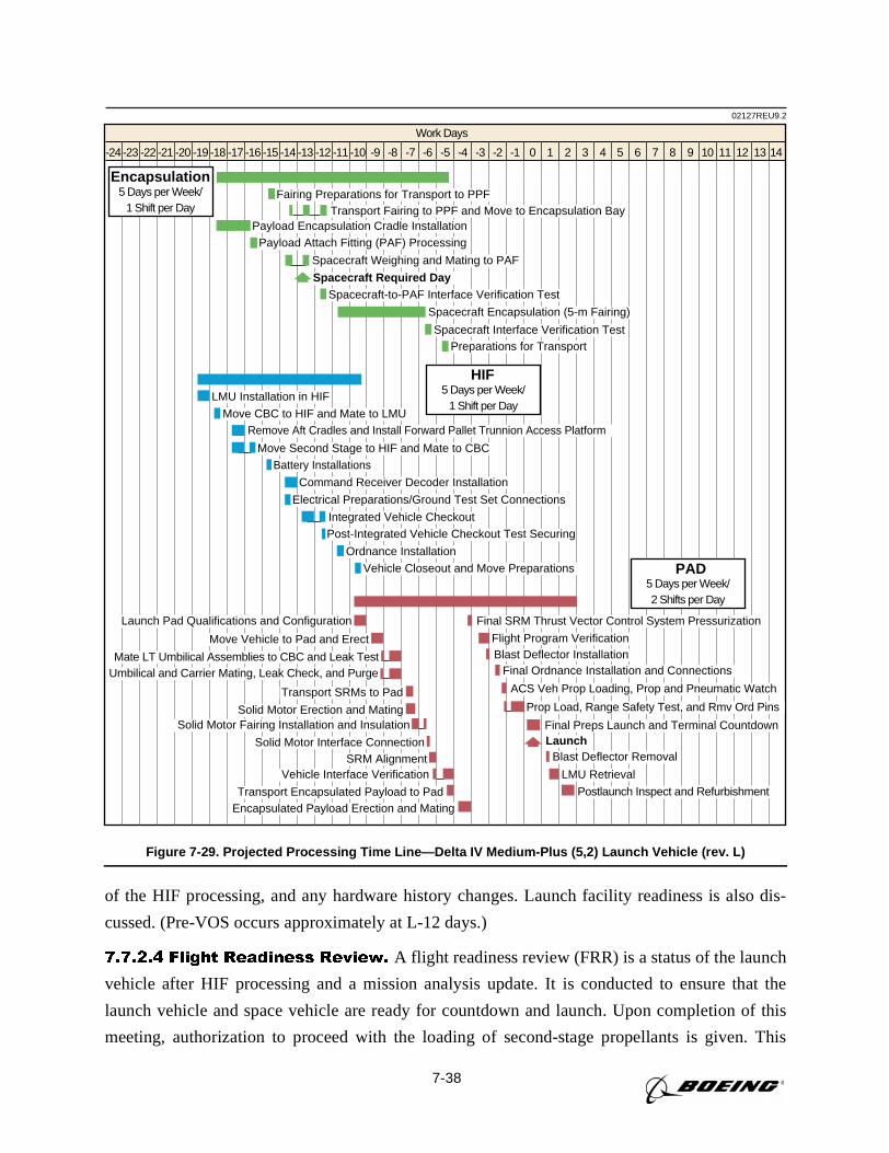
7-38
of the HIF processing, and any hardware history changes. Launch facility readiness is also dis-
cussed. (Pre-VOS occurs approximately at L-12 days.)
7.7.2.4 Flight Readiness Review. A flight readiness review (FRR) is a status of the launch
vehicle after HIF processing and a mission analysis update. It is conducted to ensure that the
launch vehicle and space vehicle are ready for countdown and launch. Upon completion of this
meeting, authorization to proceed with the loading of second-stage propellants is given. This
Work Days
-24 -23 -22 -21 -20 -19 -18 -17 -16 -15 -14 -13 -12 -11 -10 -9 -8 -7 -6 -5 -4 -3 -2 -1 0 1 2 3 4 5 6 7 8 9 10 11 12 1413
Fairing Preparations for Transport to PPFTransport Fairing to PPF and Move to Encapsulation Bay
Spacecraft Encapsulation (5-m Fairing)
Payload Encapsulation Cradle InstallationPayload Attach Fitting (PAF) Processing
Spacecraft Required DaySpacecraft-to-PAF Interface Verification Test
Spacecraft Interface Verification TestPreparations for Transport
Spacecraft Weighing and Mating to PAF
Encapsulation5 Days per Week/
1 Shift per Day
Move CBC to HIF and Mate to LMURemove Aft Cradles and Install Forward Pallet Trunnion Access Platform
Move Second Stage to HIF and Mate to CBC
Battery Installations
LMU Installation in HIF
Ordnance Installation
Vehicle Closeout and Move Preparations
Command Receiver Decoder Installation
Electrical Preparations/Ground Test Set Connections
Integrated Vehicle CheckoutPost-Integrated Vehicle Checkout Test Securing
HIF5 Days per Week/
1 Shift per Day
Launch Pad Qualifications and Configuration
Move Vehicle to Pad and Erect Flight Program Verification
Mate LT Umbilical Assemblies to CBC and Leak Test
Final SRM Thrust Vector Control System Pressurization
Umbilical and Carrier Mating, Leak Check, and Purge
Transport SRMs to Pad
Solid Motor Erection and Mating
SRM Alignment
Solid Motor Fairing Installation and Insulation
Transport Encapsulated Payload to PadEncapsulated Payload Erection and Mating
Solid Motor Interface Connection
Vehicle Interface Verification
Final Ordnance Installation and ConnectionsBlast Deflector Installation
ACS Veh Prop Loading, Prop and Pneumatic Watch
Prop Load, Range Safety Test, and Rmv Ord Pins
Final Preps Launch and Terminal CountdownLaunch
Blast Deflector Removal
LMU Retrieval
Postlaunch Inspect and Refurbishment
PAD5 Days per Week/2 Shifts per Day
02127REU9.2
Figure 7-29. Projected Processing Time Line—Delta IV Medium-Plus (5,2) Launch Vehicle (rev. L)
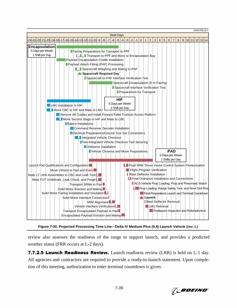
7-39
review also assesses the readiness of the range to support launch, and provides a predicted
weather status (FRR occurs at L-2 days).
7.7.2.5 Launch Readiness Review. Launch readiness review (LRR) is held on L-1 day.
All agencies and contractors are required to provide a ready-to-launch statement. Upon comple-
tion of this meeting, authorization to enter terminal countdown is given.
02007REU9.4
Work Days
-24 -23 -22 -21 -20 -19 -18 -17 -16 -15 -14 -13 -12 -11 -10 -9 -8 -7 -6 -5 -4 -3 -2 -1 0 1 2 3 4 5 6 7 8 9 10 11 12 1413
Fairing Preparations for Transport to PPFTransport to PPF and Move to Encapsulation Bay
Spacecraft Encapsulation (5-m Fairing)
Payload Encapsulation Cradle InstallationPayload Attach Fitting (PAF) Processing
Spacecraft Required DaySpacecraft-to-PAF Interface Verification Test
Spacecraft Interface Verification TestPreparations for Transport
Spacecraft Weighing and Mating to PAF
Encapsulation5 Days per Week/
1 Shift per Day
Move CBC to HIF and Mate to LMU
Remove Aft Cradles and Install Forward Pallet Trunnion Access Platform
Move Second Stage to HIF and Mate to CBC
Battery Installations
LMU Installation in HIF
Ordnance Installation
Vehicle Closeout and Move Preparations
Command Receiver Decoder Installation
Electrical Preparations/Ground Test Set ConnectionsIntegrated Vehicle CheckoutPost-Integrated Vehicle Checkout Test Securing
HIF5 Days per Week/
1 Shift per Day
Launch Pad Qualifications and Configuration
Move Vehicle to Pad and Erect Flight Program Verification
Mate LT Umb Assemblies to CBC and Leak Test
Final SRM Thrust Vector Control System Pressurization
Mate FUT Umbilicals, Leak Check, and Purge
Transport SRMs to Pad
Solid Motor Erection and Mating
SRM Alignment
Solid Motor Fairing Installation and Insulation
Transport Encapsulated Payload to PadEncapsulated Payload Erection and Mating
Solid Motor Interface Connection
Vehicle Interface Verification
Final Ordnance Installation and ConnectionsBlast Deflector Installation
ACS Vehicle Prop Loading, Prop and Pneumatic Watch
Prop Loading, Range Safety Test. and Rmvl Ord Pins
Final Preparations Launch and Terminal CountdownLaunch
Blast Deflector Removal
LMU RetrievalPostlaunch Inspection and Refurbishment
PAD5 Days per Week/2 Shifts per Day
Figure 7-30. Projected Processing Time Line—Delta IV Medium-Plus (5,4) Launch Vehicle (rev. L)
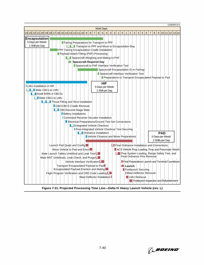
7-40
01980REU9.4
Work Days
-24 -23 -22 -21 -20 -19 -18 -17 -16 -15 -14 -13 -12 -11 -10 -9 -8 -7 -6 -5 -4 -3 -2 -1 0 1 2 3 4 5 6 7 8 9 10 11 12 1413
Fairing Preparations for Transport to PPFTransport to PPF and Move to Encapsulation Bay
Spacecraft Encapsulation (5-m Fairing)
PPF Fairing Encapsulation Cradle InstallationPayload Attach Fitting (PAF) Processing
Spacecraft Required DaySpacecraft to PAF Interface Verification Test
Spacecraft Interface Verification TestPreparations to Transport Encapsulated Payload to Pad
Spacecraft Weighing and Mating to PAF
Encapsulation5 Days per Week/
1 Shift per Day
Mate CBCs to LMUInstall BSMs in CBCSs
Mate CBCs to LMU
Battery Installations
LMU Installation in HIF
Ordnance InstallationVehicle Closeout and Move Preparations
Command Receiver Decoder Installation
CBC/CBCS Cradle Removal
Thrust Fitting and Strut Installation
CBC/Second-Stage Mate
Electrical Preparations/Ground Test Set ConnectionsIntegrated Vehicle CheckoutPost-Integrated Vehicle Checkout Test Securing
HIF5 Days per Week/
1 Shift per Day
Launch Pad Quals and Config
Move Vehicle to Pad and Erect
Final Ordnance Installation and Connections
Mate Launch Tables Umbilical and Leak Test
ACS Vehicle Prop Loading, Prop and Pneumatic Watch
Mate MST Umbilicals, Leak Check, and Purge
Prop System Loading, Range Safety Test, andFinal Ordnance Pins Removal
Vehicle Interface Verification Final Preparations Launch and Terminal Countdown
Postlaunch SecuringTransport Encapsulated Payload to Pad
Blast Deflector Installation
LaunchEncapsulated Payload Erection and Mating
Flight Program Verification and CRD Code Loading Blast Deflector Removal
LMU RetrievalPostlaunch Inspection and Refurbishment
PAD5 Days per Week/2 Shifts per Day
Figure 7-31. Projected Processing Time Line—Delta IV Heavy Launch Vehicle (rev. L)
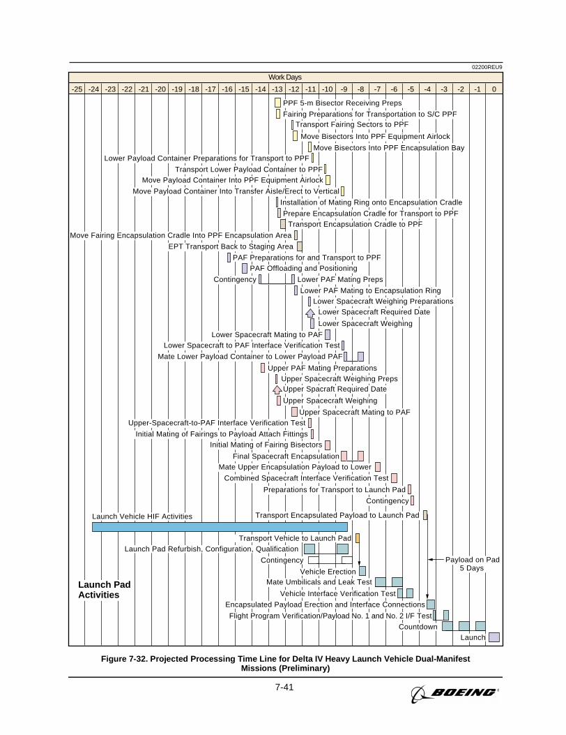
7-41
02200REU9
Work Days
-25 -24 -23 -22 -21 -20 -19 -18 -17 -16 -15 -14 -13 -12 -11 -10 -9 -8 -7 -6 -5 -4 -3 -1-2 0
Launch PadActivities
Transport Encapsulated Payload to Launch Pad
PPF 5-m Bisector Receiving Preps
Fairing Preparations for Transportation to S/C PPF
Move Bisectors Into PPF Encapsulation Bay
Installation of Mating Ring onto Encapsulation Cradle
Lower PAF Mating to Encapsulation RingLower Spacecraft Weighing Preparations
Lower Spacecraft Required Date
Lower Spacecraft Weighing
PAF Preparations for and Transport to PPFPAF Offloading and Positioning
Lower PAF Mating PrepsContingency
Prepare Encapsulation Cradle for Transport to PPFTransport Encapsulation Cradle to PPF
Move Fairing Encapsulation Cradle Into PPF Encapsulation Area
Lower Spacecraft Mating to PAFLower Spacecraft to PAF Interface Verification Test
Mate Lower Payload Container to Lower Payload PAF
Upper-Spacecraft-to-PAF Interface Verification Test
Initial Mating of Fairings to Payload Attach FittingsInitial Mating of Fairing Bisectors
Final Spacecraft EncapsulationMate Upper Encapsulation Payload to Lower
Combined Spacecraft Interface Verification Test
Preparations for Transport to Launch Pad
Contingency
Upper PAF Mating PreparationsUpper Spacecraft Weighing PrepsUpper Spacraft Required Date
Upper Spacecraft Weighing
Upper Spacecraft Mating to PAF
EPT Transport Back to Staging Area
Lower Payload Container Preparations for Transport to PPF
Transport Lower Payload Container to PPFMove Payload Container Into PPF Equipment Airlock
Move Payload Container Into Transfer Aisle/Erect to Vertical
Transport Fairing Sectors to PPF
Move Bisectors Into PPF Equipment Airlock
Launch Pad Refurbish, Configuration, Qualification
Contingency
Vehicle Erection
Vehicle Interface Verification Test
Encapsulated Payload Erection and Interface Connections
Flight Program Verification/Payload No. 1 and No. 2 I/F Test
Transport Vehicle to Launch Pad
Launch
Launch Vehicle HIF Activities
Mate Umbilicals and Leak Test
Countdown
Payload on Pad5 Days
Figure 7-32. Projected Processing Time Line for Delta IV Heavy Launch Vehicle Dual-ManifestMissions (Preliminary)
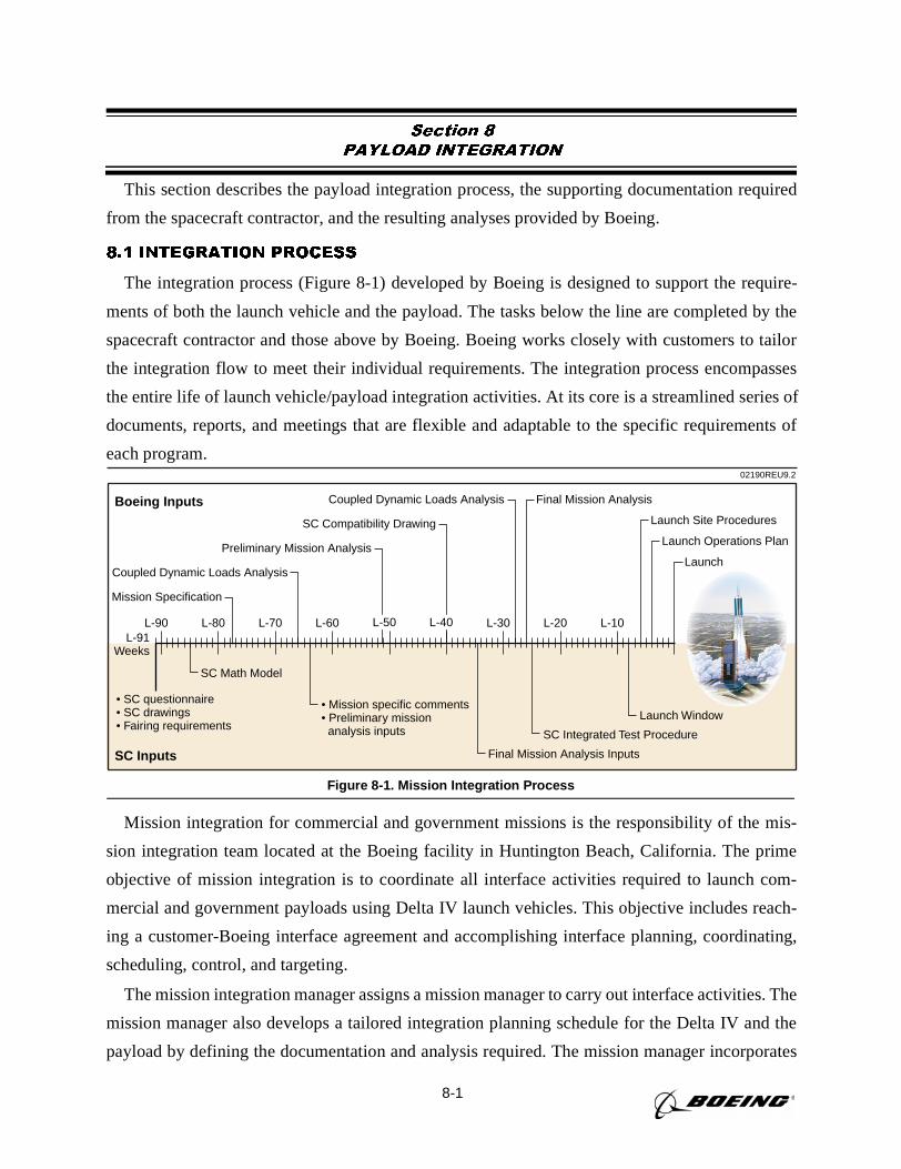
8-1
Section 8
PAYLOAD INTEGRATION
This section describes the payload integration process, the supporting documentation required
from the spacecraft contractor, and the resulting analyses provided by Boeing.
8.1 INTEGRATION PROCESS
The integration process (Figure 8-1) developed by Boeing is designed to support the require-
ments of both the launch vehicle and the payload. The tasks below the line are completed by the
spacecraft contractor and those above by Boeing. Boeing works closely with customers to tailor
the integration flow to meet their individual requirements. The integration process encompasses
the entire life of launch vehicle/payload integration activities. At its core is a streamlined series of
documents, reports, and meetings that are flexible and adaptable to the specific requirements of
each program.
Mission integration for commercial and government missions is the responsibility of the mis-
sion integration team located at the Boeing facility in Huntington Beach, California. The prime
objective of mission integration is to coordinate all interface activities required to launch com-
mercial and government payloads using Delta IV launch vehicles. This objective includes reach-
ing a customer-Boeing interface agreement and accomplishing interface planning, coordinating,
scheduling, control, and targeting.
The mission integration manager assigns a mission manager to carry out interface activities. The
mission manager also develops a tailored integration planning schedule for the Delta IV and the
payload by defining the documentation and analysis required. The mission manager incorporates
• SC questionnaire• SC drawings• Fairing requirements
• Mission specific comments• Preliminary mission analysis inputs
Boeing Inputs
SC Inputs
Mission Specification
Coupled Dynamic Loads Analysis Final Mission Analysis
Final Mission Analysis Inputs
Launch Site Procedures
Launch Window
SC Integrated Test Procedure
SC Math Model
Launch Operations Plan
LaunchCoupled Dynamic Loads Analysis
Preliminary Mission Analysis
SC Compatibility Drawing
L-91Weeks
L-90 L-80 L-70 L-60 L-30 L-20 L-10
02190REU9.2
L-50 L-40
Figure 8-1. Mission Integration Process
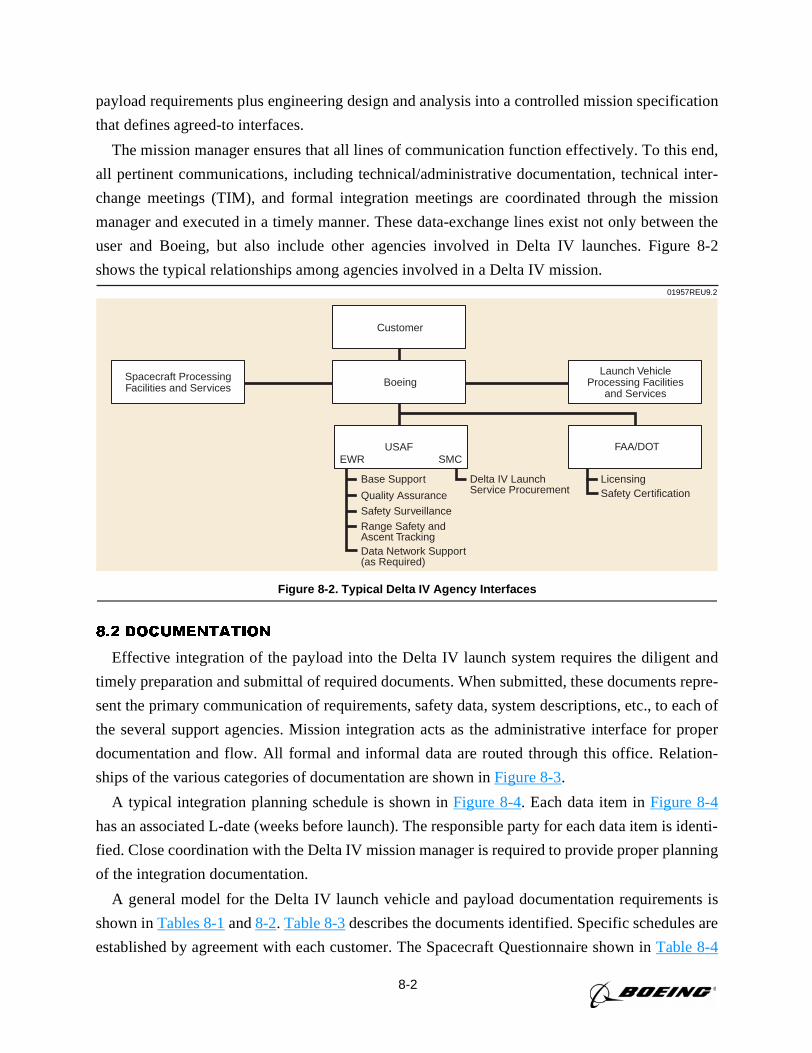
8-2
payload requirements plus engineering design and analysis into a controlled mission specification
that defines agreed-to interfaces.
The mission manager ensures that all lines of communication function effectively. To this end,
all pertinent communications, including technical/administrative documentation, technical inter-
change meetings (TIM), and formal integration meetings are coordinated through the mission
manager and executed in a timely manner. These data-exchange lines exist not only between the
user and Boeing, but also include other agencies involved in Delta IV launches. Figure 8-2
shows the typical relationships among agencies involved in a Delta IV mission.
8.2 DOCUMENTATION
Effective integration of the payload into the Delta IV launch system requires the diligent and
timely preparation and submittal of required documents. When submitted, these documents repre-
sent the primary communication of requirements, safety data, system descriptions, etc., to each of
the several support agencies. Mission integration acts as the administrative interface for proper
documentation and flow. All formal and informal data are routed through this office. Relation-
ships of the various categories of documentation are shown inFigure 8-3.
A typical integration planning schedule is shown inFigure 8-4. Each data item inFigure 8-4
has an associated L-date (weeks before launch). The responsible party for each data item is identi-
fied. Close coordination with the Delta IV mission manager is required to provide proper planning
of the integration documentation.
A general model for the Delta IV launch vehicle and payload documentation requirements is
shown inTables 8-1and8-2. Table 8-3describes the documents identified. Specific schedules are
established by agreement with each customer. The Spacecraft Questionnaire shown inTable 8-4
USAF
Base Support
Quality Assurance
Safety SurveillanceRange Safety and Ascent TrackingData Network Support (as Required)
Delta IV LaunchService Procurement
LicensingSafety Certification
EWR
Boeing
FAA/DOTSMC
Launch VehicleProcessing Facilities
and Services
Customer
Spacecraft ProcessingFacilities and Services
01957REU9.2
Figure 8-2. Typical Delta IV Agency Interfaces
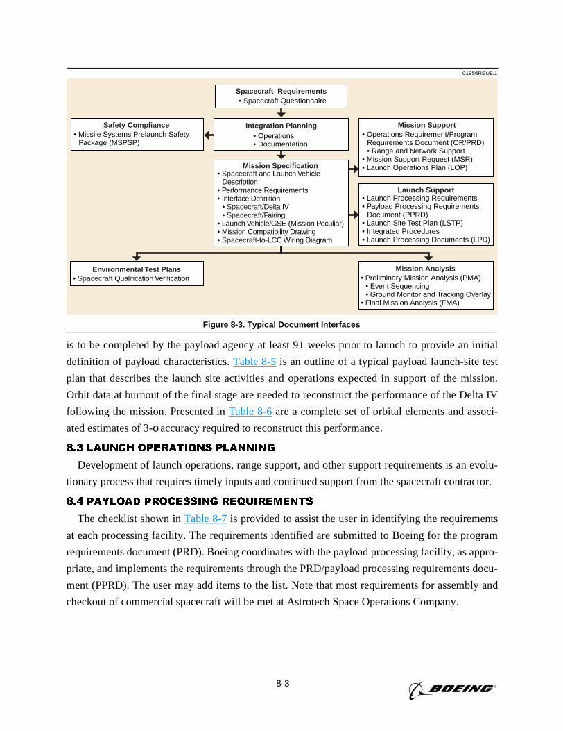
8-3
is to be completed by the payload agency at least 91 weeks prior to launch to provide an initial
definition of payload characteristics.Table 8-5is an outline of a typical payload launch-site test
plan that describes the launch site activities and operations expected in support of the mission.
Orbit data at burnout of the final stage are needed to reconstruct the performance of the Delta IV
following the mission. Presented inTable 8-6are a complete set of orbital elements and associ-
ated estimates of 3-σaccuracy required to reconstruct this performance.
8.3 LAUNCH OPERATIONS PLANNING
Development of launch operations, range support, and other support requirements is an evolu-
tionary process that requires timely inputs and continued support from the spacecraft contractor.
8.4 PAYLOAD PROCESSING REQUIREMENTS
The checklist shown inTable 8-7is provided to assist the user in identifying the requirements
at each processing facility. The requirements identified are submitted to Boeing for the program
requirements document (PRD). Boeing coordinates with the payload processing facility, as appro-
priate, and implements the requirements through the PRD/payload processing requirements docu-
ment (PPRD). The user may add items to the list. Note that most requirements for assembly and
checkout of commercial spacecraft will be met at Astrotech Space Operations Company.
01956REU9.1
• Preliminary Mission Analysis (PMA)• Event Sequencing• Ground Monitor and Tracking Overlay
• Final Mission Analysis (FMA)
Mission Analysis
• Operations Requirement/ProgramRequirements Document (OR/PRD) • Range and Network Support
• Mission Support Request (MSR)• Launch Operations Plan (LOP)
Mission Support
• Launch Processing Requirements• Payload Processing Requirements
Document (PPRD)• Launch Site Test Plan (LSTP)• Integrated Procedures• Launch Processing Documents (LPD)
Launch Support
• Missile Systems Prelaunch SafetyPackage (MSPSP)
Safety Compliance
• Spacecraft QuestionnaireSpacecraft Requirements
• Operations• Documentation
Integration Planning
• Spacecraft and Launch VehicleDescription
• Performance Requirements• Interface Definition
• Spacecraft/Delta IV• Spacecraft/Fairing
• Launch Vehicle/GSE (Mission Peculiar)• Mission Compatibility Drawing• Spacecraft-to-LCC Wiring Diagram
Mission Specification
Environmental Test Plans• Spacecraft Qualification Verification
Figure 8-3. Typical Document Interfaces
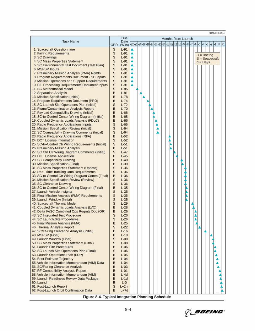
8-4
01958REU9.3
Months From LaunchTask Name
OPR
DueDate(Wks) -22 -21 -20 -19 -18 -17 -16 -15 -14 -13 -12 -11 -10 -9 -8 -7 -6 -5 -4 -3 -2 -1 0 +1
1. Spacecraft Questionnaire 2. Fairing Requirements 3. SC Drawings 4. SC Mass Properties Statement 5. SC Environmental Test Document (Test Plan) 6. MSPSP Inputs 7. Preliminary Mission Analysis (PMA) Rqmts 8. Program Requirements Document - SC Inputs 9. Mission Operations and Support Requirements10. P/L Processing Requirements Document Inputs11. SC Mathematical Model 12. Separation Analysis13. Mission Specification (Initial)14. Program Requirements Document (PRD)15. SC Launch Site Operations Plan (Initial)16. Plume/Contamination Analysis Report17. Payload Compatibility Drawing (Initial)18. SC-to-Control Center Wiring Diagram (Initial)19. Coupled Dynamic Loads Analysis (FDLC)20. Radio Frequency Applications Inputs21. Mission Specification Review (Initial) 22. SC Compatibility Drawing Comments (Initial)23. Radio Frequency Applications (RFA)24. DOT License Information25. SC-to-Control Ctr Wiring Requirements (Initial)26. Preliminary Mission Analysis27. SC Ctrl Ctr Wiring Diagram Comments (Initial)28. DOT License Application29. SC Compatibility Drawing30. Mission Specification (Final)31. SC Mass Properties Statement (Update)32. Real-Time Tracking Data Requirements33. SC-to-Control Ctr Wiring Diagram Comm (Final)34. Mission Specification Review (Review)35. SC Clearance Drawing36. SC-to-Control Center Wiring Diagram (Final)37. Launch Vehicle Insignia38. Final Mission Analysis (FMA) Requirements39. Launch Window (Initial)40. Spacecraft Thermal Model41. Coupled Dynamic Loads Analysis (LVC)42. Delta IV/SC Combined Ops Reqmts Doc (OR)43. SC Integrated Test Procedure44. SC Launch Site Procedures45. Final Mission Analysis (FMA)46. Thermal Analysis Report47. SC/Fairing Clearance Analysis (Initial)48. MSPSP (Final)49. Launch Window (Final)50. SC Mass Properties Statement (Final)51. Launch Site Procedures52. SC Launch Site Operations Plan (Final)53. Launch Operations Plan (LOP)54. Best-Estimate Trajectory55. Vehicle Information Memorandum (VIM) Data56. SC/Fairing Clearance Analysis57. RF Compatibility Analysis Report58. Vehicle Information Memorandum (VIM)59. Launch Readiness Review Data Package60. Launch61. Post-Launch Report62. Post-Launch Orbit Confirmation Data
SSSSSSSSSSSBBBSBBBBSSSBSSBSBBBSSBSSBSSSSBBSSBSBBSSBSBBBBBBBBSB
L-91L-91L-91L-91L-91L-91L-91L-91L-91L-91L-85L-81L-78L-74L-72L-70L-68L-68L-66L-65L-64L-64L-52L-52L-51L-51L-47L-45L-40L-39L-36L-36L-36L-36L-36L-35L-35L-35L-35L-29L-28L-26L-26L-26L-25L-22L-16L-10L-08L-08L-06L-06L-05L-04L-04L-03L-01L-4dL-1dL-0
L+2hrL+7d
B = BoeingS = Spacecraft d = Days
Figure 8-4. Typical Integration Planning Schedule
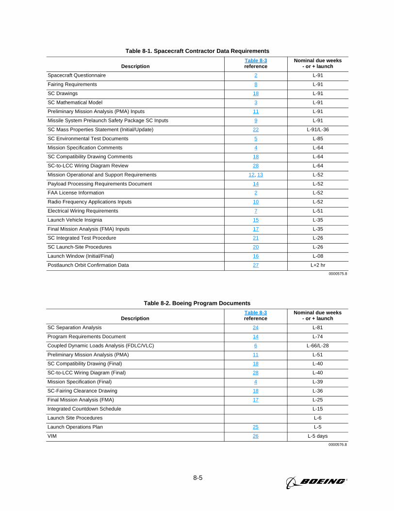
8-5
Table 8-1. Spacecraft Contractor Data Requirements
DescriptionTable 8-3reference
Nominal due weeks- or + launch
Spacecraft Questionnaire 2 L-91
Fairing Requirements 8 L-91
SC Drawings 18 L-91
SC Mathematical Model 3 L-91
Preliminary Mission Analysis (PMA) Inputs 11 L-91
Missile System Prelaunch Safety Package SC Inputs 9 L-91
SC Mass Properties Statement (Initial/Update) 22 L-91/L-36
SC Environmental Test Documents 5 L-85
Mission Specification Comments 4 L-64
SC Compatibility Drawing Comments 18 L-64
SC-to-LCC Wiring Diagram Review 28 L-64
Mission Operational and Support Requirements 12, 13 L-52
Payload Processing Requirements Document 14 L-52
FAA License Information 2 L-52
Radio Frequency Applications Inputs 10 L-52
Electrical Wiring Requirements 7 L-51
Launch Vehicle Insignia 15 L-35
Final Mission Analysis (FMA) Inputs 17 L-35
SC Integrated Test Procedure 21 L-26
SC Launch-Site Procedures 20 L-26
Launch Window (Initial/Final) 16 L-08
Postlaunch Orbit Confirmation Data 27 L+2 hr
0000575.8
Table 8-2. Boeing Program Documents
DescriptionTable 8-3reference
Nominal due weeks- or + launch
SC Separation Analysis 24 L-81
Program Requirements Document 14 L-74
Coupled Dynamic Loads Analysis (FDLC/VLC) 6 L-66/L-28
Preliminary Mission Analysis (PMA) 11 L-51
SC Compatibility Drawing (Final) 18 L-40
SC-to-LCC Wiring Diagram (Final) 28 L-40
Mission Specification (Final) 4 L-39
SC-Fairing Clearance Drawing 18 L-36
Final Mission Analysis (FMA) 17 L-25
Integrated Countdown Schedule L-15
Launch Site Procedures L-6
Launch Operations Plan 25 L-5
VIM 26 L-5 days
0000576.8
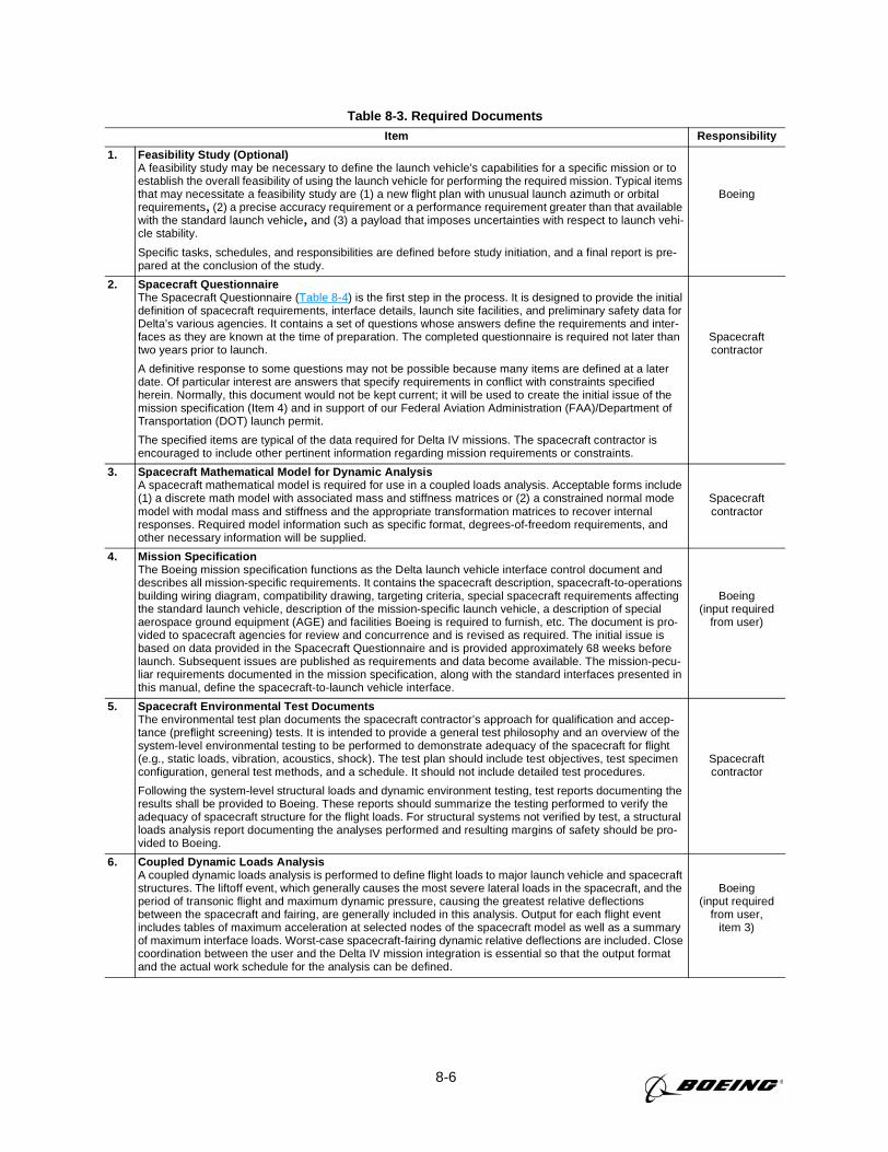
8-6
Table 8-3. Required DocumentsItem Responsibility
1. Feasibility Study (Optional)A feasibility study may be necessary to define the launch vehicle’s capabilities for a specific mission or toestablish the overall feasibility of using the launch vehicle for performing the required mission. Typical itemsthat may necessitate a feasibility study are (1) a new flight plan with unusual launch azimuth or orbitalrequirements, (2) a precise accuracy requirement or a performance requirement greater than that availablewith the standard launch vehicle, and (3) a payload that imposes uncertainties with respect to launch vehi-cle stability.
Specific tasks, schedules, and responsibilities are defined before study initiation, and a final report is pre-pared at the conclusion of the study.
Boeing
2. Spacecraft QuestionnaireThe Spacecraft Questionnaire (Table 8-4) is the first step in the process. It is designed to provide the initialdefinition of spacecraft requirements, interface details, launch site facilities, and preliminary safety data forDelta’s various agencies. It contains a set of questions whose answers define the requirements and inter-faces as they are known at the time of preparation. The completed questionnaire is required not later thantwo years prior to launch.
A definitive response to some questions may not be possible because many items are defined at a laterdate. Of particular interest are answers that specify requirements in conflict with constraints specifiedherein. Normally, this document would not be kept current; it will be used to create the initial issue of themission specification (Item 4) and in support of our Federal Aviation Administration (FAA)/Department ofTransportation (DOT) launch permit.
The specified items are typical of the data required for Delta IV missions. The spacecraft contractor isencouraged to include other pertinent information regarding mission requirements or constraints.
Spacecraftcontractor
3. Spacecraft Mathematical Model for Dynamic AnalysisA spacecraft mathematical model is required for use in a coupled loads analysis. Acceptable forms include(1) a discrete math model with associated mass and stiffness matrices or (2) a constrained normal modemodel with modal mass and stiffness and the appropriate transformation matrices to recover internalresponses. Required model information such as specific format, degrees-of-freedom requirements, andother necessary information will be supplied.
Spacecraftcontractor
4. Mission SpecificationThe Boeing mission specification functions as the Delta launch vehicle interface control document anddescribes all mission-specific requirements. It contains the spacecraft description, spacecraft-to-operationsbuilding wiring diagram, compatibility drawing, targeting criteria, special spacecraft requirements affectingthe standard launch vehicle, description of the mission-specific launch vehicle, a description of specialaerospace ground equipment (AGE) and facilities Boeing is required to furnish, etc. The document is pro-vided to spacecraft agencies for review and concurrence and is revised as required. The initial issue isbased on data provided in the Spacecraft Questionnaire and is provided approximately 68 weeks beforelaunch. Subsequent issues are published as requirements and data become available. The mission-pecu-liar requirements documented in the mission specification, along with the standard interfaces presented inthis manual, define the spacecraft-to-launch vehicle interface.
Boeing(input required
from user)
5. Spacecraft Environmental Test DocumentsThe environmental test plan documents the spacecraft contractor’s approach for qualification and accep-tance (preflight screening) tests. It is intended to provide a general test philosophy and an overview of thesystem-level environmental testing to be performed to demonstrate adequacy of the spacecraft for flight(e.g., static loads, vibration, acoustics, shock). The test plan should include test objectives, test specimenconfiguration, general test methods, and a schedule. It should not include detailed test procedures.
Following the system-level structural loads and dynamic environment testing, test reports documenting theresults shall be provided to Boeing. These reports should summarize the testing performed to verify theadequacy of spacecraft structure for the flight loads. For structural systems not verified by test, a structuralloads analysis report documenting the analyses performed and resulting margins of safety should be pro-vided to Boeing.
Spacecraftcontractor
6. Coupled Dynamic Loads AnalysisA coupled dynamic loads analysis is performed to define flight loads to major launch vehicle and spacecraftstructures. The liftoff event, which generally causes the most severe lateral loads in the spacecraft, and theperiod of transonic flight and maximum dynamic pressure, causing the greatest relative deflectionsbetween the spacecraft and fairing, are generally included in this analysis. Output for each flight eventincludes tables of maximum acceleration at selected nodes of the spacecraft model as well as a summaryof maximum interface loads. Worst-case spacecraft-fairing dynamic relative deflections are included. Closecoordination between the user and the Delta IV mission integration is essential so that the output formatand the actual work schedule for the analysis can be defined.
Boeing(input required
from user,item 3)
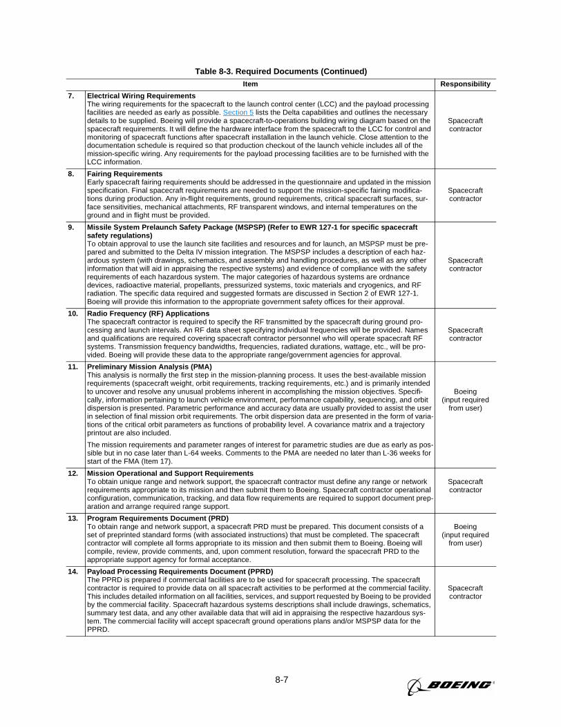
8-7
Table 8-3. Required Documents (Continued)Item Responsibility
7. Electrical Wiring RequirementsThe wiring requirements for the spacecraft to the launch control center (LCC) and the payload processingfacilities are needed as early as possible. Section 5 lists the Delta capabilities and outlines the necessarydetails to be supplied. Boeing will provide a spacecraft-to-operations building wiring diagram based on thespacecraft requirements. It will define the hardware interface from the spacecraft to the LCC for control andmonitoring of spacecraft functions after spacecraft installation in the launch vehicle. Close attention to thedocumentation schedule is required so that production checkout of the launch vehicle includes all of themission-specific wiring. Any requirements for the payload processing facilities are to be furnished with theLCC information.
Spacecraftcontractor
8. Fairing RequirementsEarly spacecraft fairing requirements should be addressed in the questionnaire and updated in the missionspecification. Final spacecraft requirements are needed to support the mission-specific fairing modifica-tions during production. Any in-flight requirements, ground requirements, critical spacecraft surfaces, sur-face sensitivities, mechanical attachments, RF transparent windows, and internal temperatures on theground and in flight must be provided.
Spacecraftcontractor
9. Missile System Prelaunch Safety Package (MSPSP) (Refer to EWR 127-1 for specific spacecraftsafety regulations)To obtain approval to use the launch site facilities and resources and for launch, an MSPSP must be pre-pared and submitted to the Delta IV mission integration. The MSPSP includes a description of each haz-ardous system (with drawings, schematics, and assembly and handling procedures, as well as any otherinformation that will aid in appraising the respective systems) and evidence of compliance with the safetyrequirements of each hazardous system. The major categories of hazardous systems are ordnancedevices, radioactive material, propellants, pressurized systems, toxic materials and cryogenics, and RFradiation. The specific data required and suggested formats are discussed in Section 2 of EWR 127-1.Boeing will provide this information to the appropriate government safety offices for their approval.
Spacecraftcontractor
10. Radio Frequency (RF) ApplicationsThe spacecraft contractor is required to specify the RF transmitted by the spacecraft during ground pro-cessing and launch intervals. An RF data sheet specifying individual frequencies will be provided. Namesand qualifications are required covering spacecraft contractor personnel who will operate spacecraft RFsystems. Transmission frequency bandwidths, frequencies, radiated durations, wattage, etc., will be pro-vided. Boeing will provide these data to the appropriate range/government agencies for approval.
Spacecraftcontractor
11. Preliminary Mission Analysis (PMA)This analysis is normally the first step in the mission-planning process. It uses the best-available missionrequirements (spacecraft weight, orbit requirements, tracking requirements, etc.) and is primarily intendedto uncover and resolve any unusual problems inherent in accomplishing the mission objectives. Specifi-cally, information pertaining to launch vehicle environment, performance capability, sequencing, and orbitdispersion is presented. Parametric performance and accuracy data are usually provided to assist the userin selection of final mission orbit requirements. The orbit dispersion data are presented in the form of varia-tions of the critical orbit parameters as functions of probability level. A covariance matrix and a trajectoryprintout are also included.
The mission requirements and parameter ranges of interest for parametric studies are due as early as pos-sible but in no case later than L-64 weeks. Comments to the PMA are needed no later than L-36 weeks forstart of the FMA (Item 17).
Boeing(input required
from user)
12. Mission Operational and Support RequirementsTo obtain unique range and network support, the spacecraft contractor must define any range or networkrequirements appropriate to its mission and then submit them to Boeing. Spacecraft contractor operationalconfiguration, communication, tracking, and data flow requirements are required to support document prep-aration and arrange required range support.
Spacecraftcontractor
13. Program Requirements Document (PRD)To obtain range and network support, a spacecraft PRD must be prepared. This document consists of aset of preprinted standard forms (with associated instructions) that must be completed. The spacecraftcontractor will complete all forms appropriate to its mission and then submit them to Boeing. Boeing willcompile, review, provide comments, and, upon comment resolution, forward the spacecraft PRD to theappropriate support agency for formal acceptance.
Boeing(input required
from user)
14. Payload Processing Requirements Document (PPRD)The PPRD is prepared if commercial facilities are to be used for spacecraft processing. The spacecraftcontractor is required to provide data on all spacecraft activities to be performed at the commercial facility.This includes detailed information on all facilities, services, and support requested by Boeing to be providedby the commercial facility. Spacecraft hazardous systems descriptions shall include drawings, schematics,summary test data, and any other available data that will aid in appraising the respective hazardous sys-tem. The commercial facility will accept spacecraft ground operations plans and/or MSPSP data for thePPRD.
Spacecraftcontractor
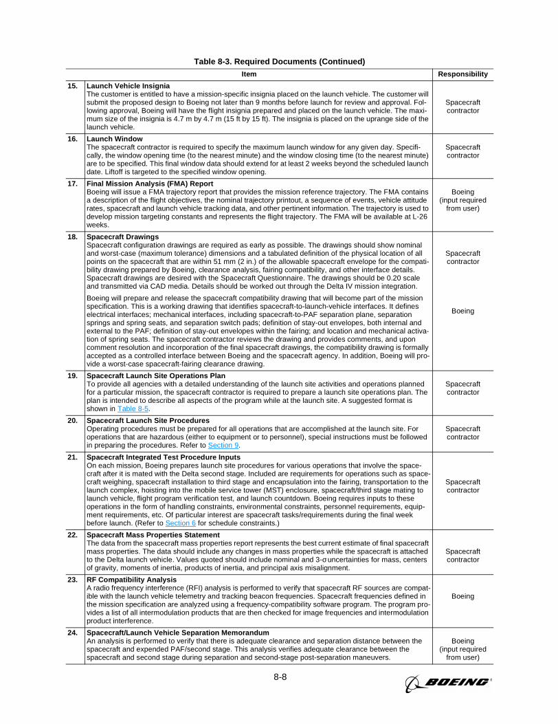
8-8
Table 8-3. Required Documents (Continued)Item Responsibility
15. Launch Vehicle InsigniaThe customer is entitled to have a mission-specific insignia placed on the launch vehicle. The customer willsubmit the proposed design to Boeing not later than 9 months before launch for review and approval. Fol-lowing approval, Boeing will have the flight insignia prepared and placed on the launch vehicle. The maxi-mum size of the insignia is 4.7 m by 4.7 m (15 ft by 15 ft). The insignia is placed on the uprange side of thelaunch vehicle.
Spacecraftcontractor
16. Launch WindowThe spacecraft contractor is required to specify the maximum launch window for any given day. Specifi-cally, the window opening time (to the nearest minute) and the window closing time (to the nearest minute)are to be specified. This final window data should extend for at least 2 weeks beyond the scheduled launchdate. Liftoff is targeted to the specified window opening.
Spacecraftcontractor
17. Final Mission Analysis (FMA) ReportBoeing will issue a FMA trajectory report that provides the mission reference trajectory. The FMA containsa description of the flight objectives, the nominal trajectory printout, a sequence of events, vehicle attituderates, spacecraft and launch vehicle tracking data, and other pertinent information. The trajectory is used todevelop mission targeting constants and represents the flight trajectory. The FMA will be available at L-26weeks.
Boeing(input required
from user)
18. Spacecraft DrawingsSpacecraft configuration drawings are required as early as possible. The drawings should show nominaland worst-case (maximum tolerance) dimensions and a tabulated definition of the physical location of allpoints on the spacecraft that are within 51 mm (2 in.) of the allowable spacecraft envelope for the compati-bility drawing prepared by Boeing, clearance analysis, fairing compatibility, and other interface details.Spacecraft drawings are desired with the Spacecraft Questionnaire. The drawings should be 0.20 scaleand transmitted via CAD media. Details should be worked out through the Delta IV mission integration.
Boeing will prepare and release the spacecraft compatibility drawing that will become part of the missionspecification. This is a working drawing that identifies spacecraft-to-launch-vehicle interfaces. It defineselectrical interfaces; mechanical interfaces, including spacecraft-to-PAF separation plane, separationsprings and spring seats, and separation switch pads; definition of stay-out envelopes, both internal andexternal to the PAF; definition of stay-out envelopes within the fairing; and location and mechanical activa-tion of spring seats. The spacecraft contractor reviews the drawing and provides comments, and uponcomment resolution and incorporation of the final spacecraft drawings, the compatibility drawing is formallyaccepted as a controlled interface between Boeing and the spacecraft agency. In addition, Boeing will pro-vide a worst-case spacecraft-fairing clearance drawing.
Spacecraftcontractor
Boeing
19. Spacecraft Launch Site Operations PlanTo provide all agencies with a detailed understanding of the launch site activities and operations plannedfor a particular mission, the spacecraft contractor is required to prepare a launch site operations plan. Theplan is intended to describe all aspects of the program while at the launch site. A suggested format isshown in Table 8-5.
Spacecraftcontractor
20. Spacecraft Launch Site ProceduresOperating procedures must be prepared for all operations that are accomplished at the launch site. Foroperations that are hazardous (either to equipment or to personnel), special instructions must be followedin preparing the procedures. Refer to Section 9.
Spacecraftcontractor
21. Spacecraft Integrated Test Procedure InputsOn each mission, Boeing prepares launch site procedures for various operations that involve the space-craft after it is mated with the Delta second stage. Included are requirements for operations such as space-craft weighing, spacecraft installation to third stage and encapsulation into the fairing, transportation to thelaunch complex, hoisting into the mobile service tower (MST) enclosure, spacecraft/third stage mating tolaunch vehicle, flight program verification test, and launch countdown. Boeing requires inputs to theseoperations in the form of handling constraints, environmental constraints, personnel requirements, equip-ment requirements, etc. Of particular interest are spacecraft tasks/requirements during the final weekbefore launch. (Refer to Section 6 for schedule constraints.)
Spacecraftcontractor
22. Spacecraft Mass Properties StatementThe data from the spacecraft mass properties report represents the best current estimate of final spacecraftmass properties. The data should include any changes in mass properties while the spacecraft is attachedto the Delta launch vehicle. Values quoted should include nominal and 3-σ uncertainties for mass, centersof gravity, moments of inertia, products of inertia, and principal axis misalignment.
Spacecraftcontractor
23. RF Compatibility AnalysisA radio frequency interference (RFI) analysis is performed to verify that spacecraft RF sources are compat-ible with the launch vehicle telemetry and tracking beacon frequencies. Spacecraft frequencies defined inthe mission specification are analyzed using a frequency-compatibility software program. The program pro-vides a list of all intermodulation products that are then checked for image frequencies and intermodulationproduct interference.
Boeing
24. Spacecraft/Launch Vehicle Separation MemorandumAn analysis is performed to verify that there is adequate clearance and separation distance between thespacecraft and expended PAF/second stage. This analysis verifies adequate clearance between thespacecraft and second stage during separation and second-stage post-separation maneuvers.
Boeing(input required
from user)
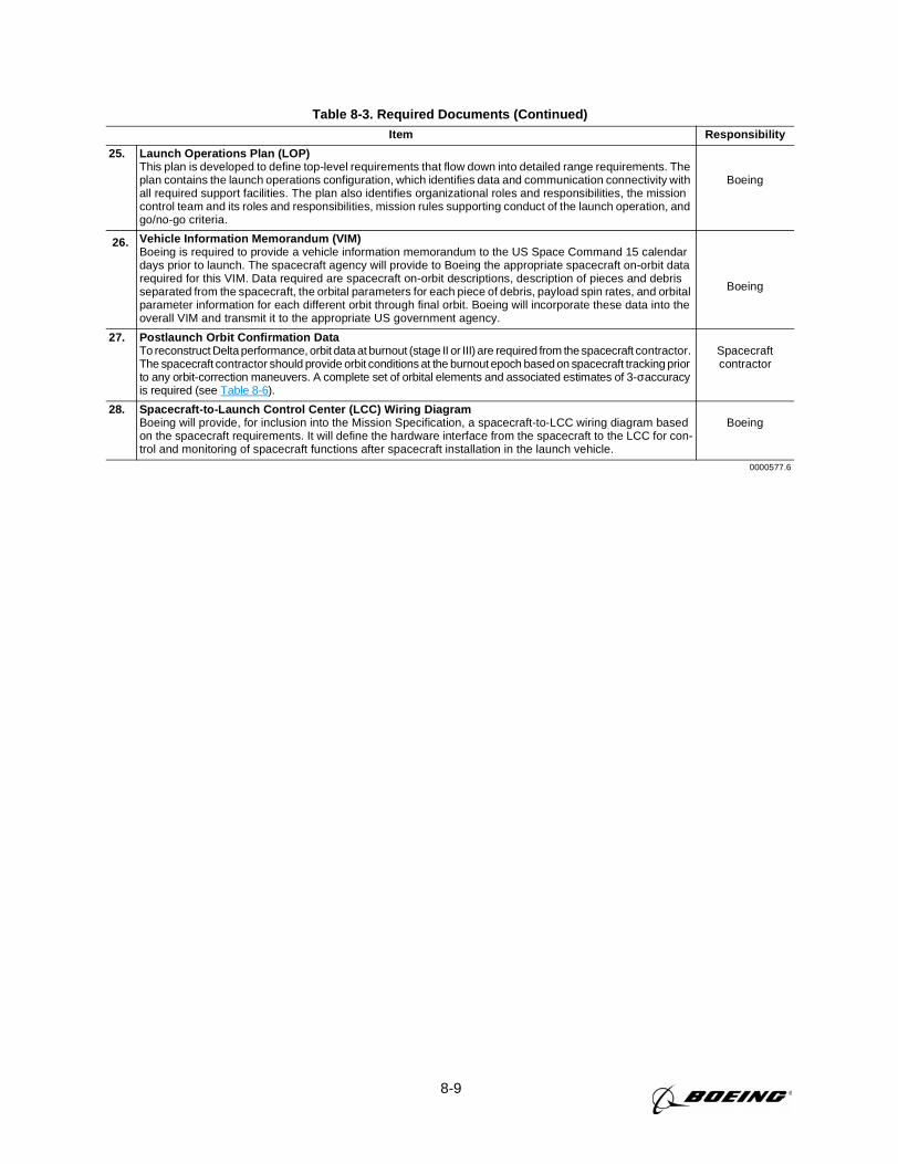
8-9
Table 8-3. Required Documents (Continued)Item Responsibility
25. Launch Operations Plan (LOP)This plan is developed to define top-level requirements that flow down into detailed range requirements. Theplan contains the launch operations configuration, which identifies data and communication connectivity withall required support facilities. The plan also identifies organizational roles and responsibilities, the missioncontrol team and its roles and responsibilities, mission rules supporting conduct of the launch operation, andgo/no-go criteria.
Boeing
26. Vehicle Information Memorandum (VIM)Boeing is required to provide a vehicle information memorandum to the US Space Command 15 calendardays prior to launch. The spacecraft agency will provide to Boeing the appropriate spacecraft on-orbit datarequired for this VIM. Data required are spacecraft on-orbit descriptions, description of pieces and debrisseparated from the spacecraft, the orbital parameters for each piece of debris, payload spin rates, and orbitalparameter information for each different orbit through final orbit. Boeing will incorporate these data into theoverall VIM and transmit it to the appropriate US government agency.
Boeing
27. Postlaunch Orbit Confirmation DataTo reconstruct Delta performance, orbit data at burnout (stage II or III) are required from the spacecraft contractor.The spacecraft contractor should provide orbit conditions at the burnout epoch based on spacecraft tracking priorto any orbit-correction maneuvers. A complete set of orbital elements and associated estimates of 3-σaccuracyis required (see Table 8-6).
Spacecraftcontractor
28. Spacecraft-to-Launch Control Center (LCC) Wiring DiagramBoeing will provide, for inclusion into the Mission Specification, a spacecraft-to-LCC wiring diagram basedon the spacecraft requirements. It will define the hardware interface from the spacecraft to the LCC for con-trol and monitoring of spacecraft functions after spacecraft installation in the launch vehicle.
Boeing
0000577.6
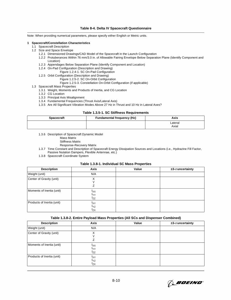
8-10
Table 8-4. Delta IV Spacecraft Questionnaire
Note: When providing numerical parameters, please specify either English or Metric units.
1 Spacecraft/Constellation Characteristics1.1 Spacecraft Description1.2 Size and Space Envelope
1.2.1 Dimensioned Drawings/CAD Model of the Spacecraft in the Launch Configuration1.2.2 Protuberances Within 76 mm/3.0 in. of Allowable Fairing Envelope Below Separation Plane (Identify Component and
Location)1.2.3 Appendages Below Separation Plane (Identify Component and Location)1.2.4 On-Pad Configuration (Description and Drawing)
Figure 1.2.4-1. SC On-Pad Configuration1.2.5 Orbit Configuration (Description and Drawing)
Figure 1.2.5-2. SC On-Orbit ConfigurationFigure 1.2.5-3. Constellation On-Orbit Configuration (if applicable)
1.3 Spacecraft Mass Properties1.3.1 Weight, Moments and Products of Inertia, and CG Location1.3.2 CG Location1.3.3 Principal Axis Misalignment1.3.4 Fundamental Frequencies (Thrust Axis/Lateral Axis)1.3.5 Are All Significant Vibration Modes Above 27 Hz in Thrust and 10 Hz in Lateral Axes?
1.3.6 Description of Spacecraft Dynamic ModelMass MatrixStiffness MatrixResponse-Recovery Matrix
1.3.7 Time Constant and Description of Spacecraft Energy Dissipation Sources and Locations (i.e., Hydrazine Fill Factor,Passive Nutation Dampers, Flexible Antennae, etc.)
1.3.8 Spacecraft Coordinate System
Table 1.3.5-1. SC Stiffness RequirementsSpacecraft Fundamental frequency (Hz) Axis
LateralAxial
Table 1.3.8-1. Individual SC Mass PropertiesDescription Axis Value ±3- σuncertainty
Weight (unit) N/A
Center of Gravity (unit) XYZ
Moments of Inertia (unit) IXXIYYIZZ
Products of Inertia (unit) IXYIYZIZX
Table 1.3.8-2. Entire Payload Mass Properties (All SCs and Dispenser Combined)Description Axis Value ±3- σuncertainty
Weight (unit) N/A
Center of Gravity (unit) XYZ
Moments of Inertia (unit) IXXIYYIZZ
Products of Inertia (unit) IXYIYZIZX
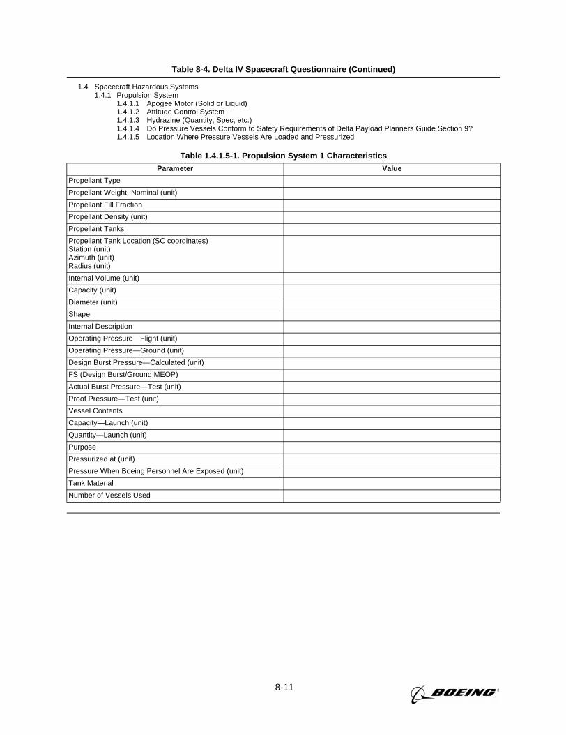
8-11
Table 8-4. Delta IV Spacecraft Questionnaire (Continued)
1.4 Spacecraft Hazardous Systems1.4.1 Propulsion System
1.4.1.1 Apogee Motor (Solid or Liquid)1.4.1.2 Attitude Control System1.4.1.3 Hydrazine (Quantity, Spec, etc.)1.4.1.4 Do Pressure Vessels Conform to Safety Requirements of Delta Payload Planners Guide Section 9?1.4.1.5 Location Where Pressure Vessels Are Loaded and Pressurized
Table 1.4.1.5-1. Propulsion System 1 CharacteristicsParameter Value
Propellant Type
Propellant Weight, Nominal (unit)
Propellant Fill Fraction
Propellant Density (unit)
Propellant Tanks
Propellant Tank Location (SC coordinates)Station (unit)Azimuth (unit)Radius (unit)
Internal Volume (unit)
Capacity (unit)
Diameter (unit)
Shape
Internal Description
Operating Pressure—Flight (unit)
Operating Pressure—Ground (unit)
Design Burst Pressure—Calculated (unit)
FS (Design Burst/Ground MEOP)
Actual Burst Pressure—Test (unit)
Proof Pressure—Test (unit)
Vessel Contents
Capacity—Launch (unit)
Quantity—Launch (unit)
Purpose
Pressurized at (unit)
Pressure When Boeing Personnel Are Exposed (unit)
Tank Material
Number of Vessels Used
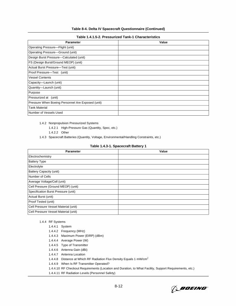
8-12
Table 8-4. Delta IV Spacecraft Questionnaire (Continued)
1.4.2 Nonpropulsion Pressurized Systems
1.4.2.1 High-Pressure Gas (Quantity, Spec, etc.)
1.4.2.2 Other
1.4.3 Spacecraft Batteries (Quantity, Voltage, Environmental/Handling Constraints, etc.)
1.4.4 RF Systems
1.4.4.1 System
1.4.4.2 Frequency (MHz)
1.4.4.3 Maximum Power (EIRP) (dBm)
1.4.4.4 Average Power (W)
1.4.4.5 Type of Transmitter
1.4.4.6 Antenna Gain (dBi)
1.4.4.7 Antenna Location
1.4.4.8 Distance at Which RF Radiation Flux Density Equals 1 mW/cm2
1.4.4.9 When Is RF Transmitter Operated?
1.4.4.10 RF Checkout Requirements (Location and Duration, to What Facility, Support Requirements, etc.)
1.4.4.11 RF Radiation Levels (Personnel Safety)
Table 1.4.1.5-2. Pressurized Tank-1 CharacteristicsParameter Value
Operating Pressure—Flight (unit)
Operating Pressure—Ground (unit)
Design Burst Pressure—Calculated (unit)
FS (Design Burst/Ground MEOP) (unit)
Actual Burst Pressure—Test (unit)
Proof Pressure—Test (unit)
Vessel Contents
Capacity—Launch (unit)
Quantity—Launch (unit)
Purpose
Pressurized at (unit)
Pressure When Boeing Personnel Are Exposed (unit)
Tank Material
Number of Vessels Used
Table 1.4.3-1. Spacecraft Battery 1Parameter Value
Electrochemistry
Battery Type
Electrolyte
Battery Capacity (unit)
Number of Cells
Average Voltage/Cell (unit)
Cell Pressure (Ground MEOP) (unit)
Specification Burst Pressure (unit)
Actual Burst (unit)
Proof Tested (unit)
Cell Pressure Vessel Material (unit)
Cell Pressure Vessel Material (unit)
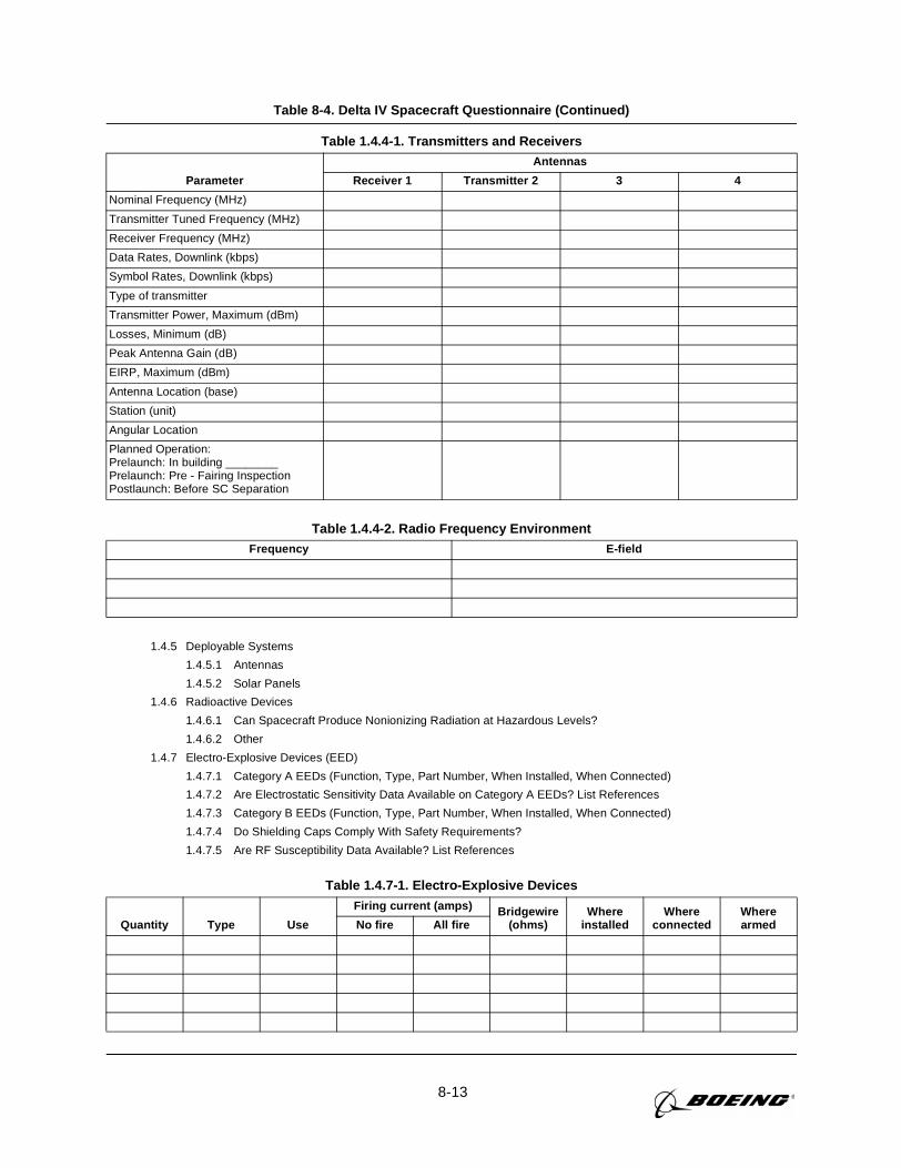
8-13
Table 8-4. Delta IV Spacecraft Questionnaire (Continued)
1.4.5 Deployable Systems
1.4.5.1 Antennas
1.4.5.2 Solar Panels
1.4.6 Radioactive Devices
1.4.6.1 Can Spacecraft Produce Nonionizing Radiation at Hazardous Levels?
1.4.6.2 Other
1.4.7 Electro-Explosive Devices (EED)
1.4.7.1 Category A EEDs (Function, Type, Part Number, When Installed, When Connected)
1.4.7.2 Are Electrostatic Sensitivity Data Available on Category A EEDs? List References
1.4.7.3 Category B EEDs (Function, Type, Part Number, When Installed, When Connected)
1.4.7.4 Do Shielding Caps Comply With Safety Requirements?
1.4.7.5 Are RF Susceptibility Data Available? List References
Table 1.4.4-1. Transmitters and Receivers
Parameter
Antennas
Receiver 1 Transmitter 2 3 4
Nominal Frequency (MHz)
Transmitter Tuned Frequency (MHz)
Receiver Frequency (MHz)
Data Rates, Downlink (kbps)
Symbol Rates, Downlink (kbps)
Type of transmitter
Transmitter Power, Maximum (dBm)
Losses, Minimum (dB)
Peak Antenna Gain (dB)
EIRP, Maximum (dBm)
Antenna Location (base)
Station (unit)
Angular Location
Planned Operation:Prelaunch: In building ________Prelaunch: Pre - Fairing InspectionPostlaunch: Before SC Separation
Table 1.4.4-2. Radio Frequency EnvironmentFrequency E-field
Table 1.4.7-1. Electro-Explosive Devices
Quantity Type Use
Firing current (amps) Bridgewire(ohms)
Whereinstalled
Whereconnected
WherearmedNo fire All fire
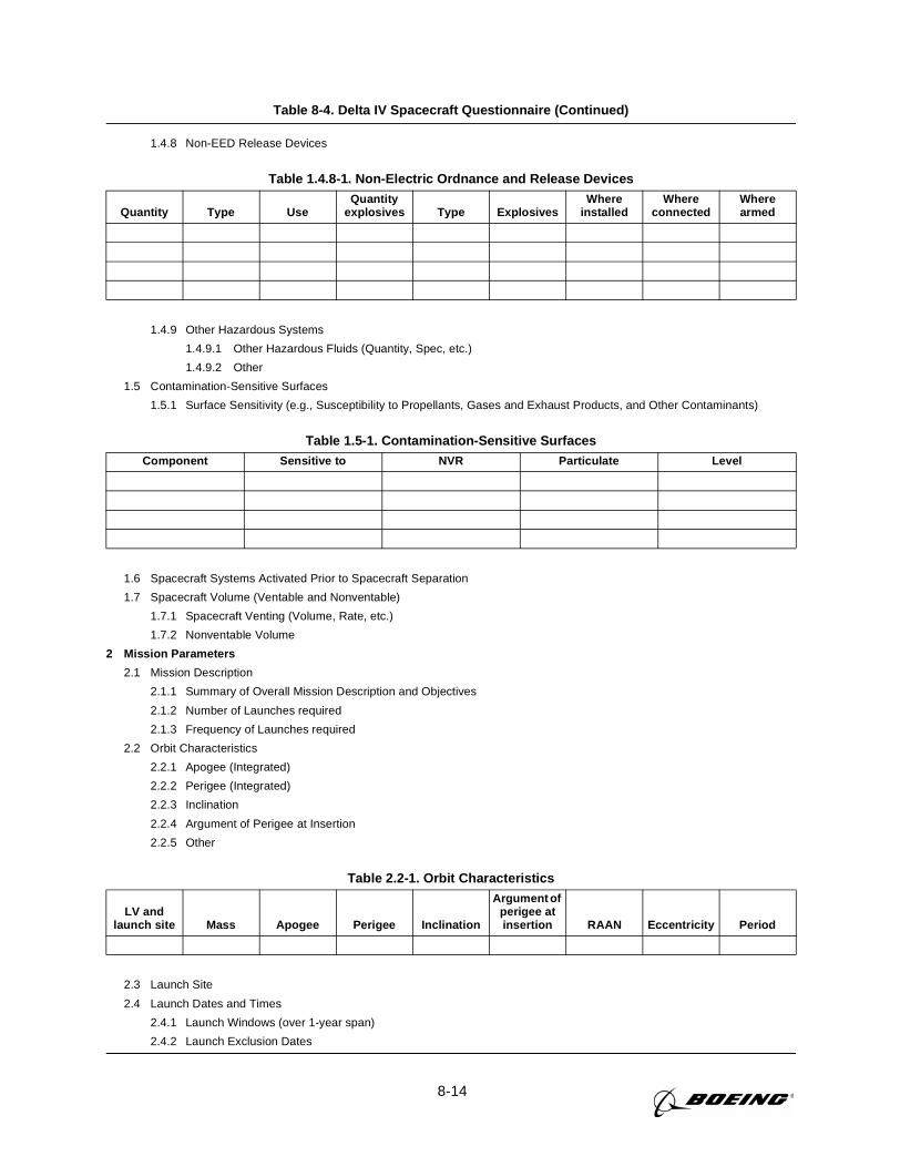
8-14
Table 8-4. Delta IV Spacecraft Questionnaire (Continued)
1.4.8 Non-EED Release Devices
1.4.9 Other Hazardous Systems
1.4.9.1 Other Hazardous Fluids (Quantity, Spec, etc.)
1.4.9.2 Other
1.5 Contamination-Sensitive Surfaces
1.5.1 Surface Sensitivity (e.g., Susceptibility to Propellants, Gases and Exhaust Products, and Other Contaminants)
1.6 Spacecraft Systems Activated Prior to Spacecraft Separation
1.7 Spacecraft Volume (Ventable and Nonventable)
1.7.1 Spacecraft Venting (Volume, Rate, etc.)
1.7.2 Nonventable Volume
2 Mission Parameters
2.1 Mission Description
2.1.1 Summary of Overall Mission Description and Objectives
2.1.2 Number of Launches required
2.1.3 Frequency of Launches required
2.2 Orbit Characteristics
2.2.1 Apogee (Integrated)
2.2.2 Perigee (Integrated)
2.2.3 Inclination
2.2.4 Argument of Perigee at Insertion
2.2.5 Other
2.3 Launch Site
2.4 Launch Dates and Times
2.4.1 Launch Windows (over 1-year span)
2.4.2 Launch Exclusion Dates
Table 1.4.8-1. Non-Electric Ordnance and Release Devices
Quantity Type UseQuantity
explosives Type ExplosivesWhere
installedWhere
connectedWherearmed
Table 1.5-1. Contamination-Sensitive SurfacesComponent Sensitive to NVR Particulate Level
Table 2.2-1. Orbit Characteristics
LV andlaunch site Mass Apogee Perigee Inclination
Argument ofperigee atinsertion RAAN Eccentricity Period
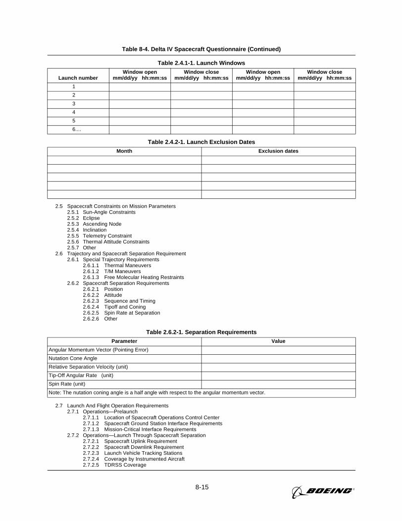
8-15
Table 8-4. Delta IV Spacecraft Questionnaire (Continued)
2.5 Spacecraft Constraints on Mission Parameters2.5.1 Sun-Angle Constraints2.5.2 Eclipse2.5.3 Ascending Node2.5.4 Inclination2.5.5 Telemetry Constraint2.5.6 Thermal Attitude Constraints2.5.7 Other
2.6 Trajectory and Spacecraft Separation Requirement2.6.1 Special Trajectory Requirements
2.6.1.1 Thermal Maneuvers2.6.1.2 T/M Maneuvers2.6.1.3 Free Molecular Heating Restraints
2.6.2 Spacecraft Separation Requirements2.6.2.1 Position2.6.2.2 Attitude2.6.2.3 Sequence and Timing2.6.2.4 Tipoff and Coning2.6.2.5 Spin Rate at Separation2.6.2.6 Other
2.7 Launch And Flight Operation Requirements2.7.1 Operations—Prelaunch
2.7.1.1 Location of Spacecraft Operations Control Center2.7.1.2 Spacecraft Ground Station Interface Requirements2.7.1.3 Mission-Critical Interface Requirements
2.7.2 Operations—Launch Through Spacecraft Separation2.7.2.1 Spacecraft Uplink Requirement2.7.2.2 Spacecraft Downlink Requirement2.7.2.3 Launch Vehicle Tracking Stations2.7.2.4 Coverage by Instrumented Aircraft2.7.2.5 TDRSS Coverage
Table 2.4.1-1. Launch Windows
Launch numberWindow open
mm/dd/yy hh:mm:ssWindow close
mm/dd/yy hh:mm:ssWindow open
mm/dd/yy hh:mm:ssWindow close
mm/dd/yy hh:mm:ss
1
2
3
4
5
6....
Table 2.4.2-1. Launch Exclusion DatesMonth Exclusion dates
Table 2.6.2-1. Separation RequirementsParameter Value
Angular Momentum Vector (Pointing Error)
Nutation Cone Angle
Relative Separation Velocity (unit)
Tip-Off Angular Rate (unit)
Spin Rate (unit)
Note: The nutation coning angle is a half angle with respect to the angular momentum vector.
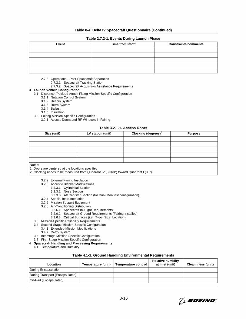
8-16
Table 8-4. Delta IV Spacecraft Questionnaire (Continued)
2.7.3 Operations—Post-Spacecraft Separation2.7.3.1 Spacecraft Tracking Station2.7.3.2 Spacecraft Acquisition Assistance Requirements
3 Launch Vehicle Configuration3.1 Dispenser/Payload Attach Fitting Mission-Specific Configuration
3.1.1 Nutation Control System3.1.2 Despin System3.1.3 Retro System3.1.4 Ballast3.1.5 Insulation
3.2 Fairing Mission-Specific Configuration3.2.1 Access Doors and RF Windows in Fairing
3.2.2 External Fairing Insulation3.2.3 Acoustic Blanket Modifications
3.2.3.1 Cylindrical Section3.2.3.2 Nose Section3.2.3.3 Aft Canister Section (for Dual-Manifest configuration)
3.2.4 Special Instrumentation3.2.5 Mission Support Equipment3.2.6 Air-Conditioning Distribution
3.2.6.1 Spacecraft In-Flight Requirements3.2.6.2 Spacecraft Ground Requirements (Fairing Installed)3.2.6.3 Critical Surfaces (i.e., Type, Size, Location)
3.3 Mission-Specific Reliability Requirements3.4 Second-Stage Mission-Specific Configuration
3.4.1 Extended-Mission Modifications3.4.2 Retro System
3.5 Interstage Mission-Specific Configuration3.6 First-Stage Mission-Specific Configuration
4 Spacecraft Handling and Processing Requirements4.1 Temperature and Humidity
Table 2.7.2-1. Events During Launch PhaseEvent Time from liftoff Constraints/comments
Table 3.2.1-1. Access DoorsSize (unit) LV station (unit) 1 Clocking (degrees) 2 Purpose
Notes:1. Doors are centered at the locations specified.2. Clocking needs to be measured from Quadrant IV (0/360°) toward Quadrant I (90°).
Table 4.1-1. Ground Handling Environmental Requirements
Location Temperature (unit) Temperature controlRelative humidity
at inlet (unit) Cleanliness (unit)
During Encapsulation
During Transport (Encapsulated)
On-Pad (Encapsulated)
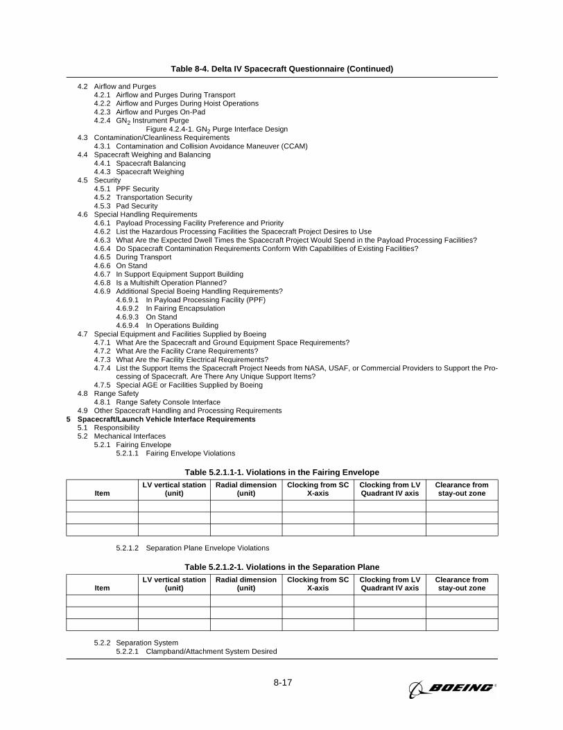
8-17
Table 8-4. Delta IV Spacecraft Questionnaire (Continued)
4.2 Airflow and Purges4.2.1 Airflow and Purges During Transport4.2.2 Airflow and Purges During Hoist Operations4.2.3 Airflow and Purges On-Pad4.2.4 GN2 Instrument Purge
Figure 4.2.4-1. GN2 Purge Interface Design4.3 Contamination/Cleanliness Requirements
4.3.1 Contamination and Collision Avoidance Maneuver (CCAM)4.4 Spacecraft Weighing and Balancing
4.4.1 Spacecraft Balancing4.4.3 Spacecraft Weighing
4.5 Security4.5.1 PPF Security4.5.2 Transportation Security4.5.3 Pad Security
4.6 Special Handling Requirements4.6.1 Payload Processing Facility Preference and Priority4.6.2 List the Hazardous Processing Facilities the Spacecraft Project Desires to Use4.6.3 What Are the Expected Dwell Times the Spacecraft Project Would Spend in the Payload Processing Facilities?4.6.4 Do Spacecraft Contamination Requirements Conform With Capabilities of Existing Facilities?4.6.5 During Transport4.6.6 On Stand4.6.7 In Support Equipment Support Building4.6.8 Is a Multishift Operation Planned?4.6.9 Additional Special Boeing Handling Requirements?
4.6.9.1 In Payload Processing Facility (PPF)4.6.9.2 In Fairing Encapsulation4.6.9.3 On Stand4.6.9.4 In Operations Building
4.7 Special Equipment and Facilities Supplied by Boeing4.7.1 What Are the Spacecraft and Ground Equipment Space Requirements?4.7.2 What Are the Facility Crane Requirements?4.7.3 What Are the Facility Electrical Requirements?4.7.4 List the Support Items the Spacecraft Project Needs from NASA, USAF, or Commercial Providers to Support the Pro-
cessing of Spacecraft. Are There Any Unique Support Items?4.7.5 Special AGE or Facilities Supplied by Boeing
4.8 Range Safety4.8.1 Range Safety Console Interface
4.9 Other Spacecraft Handling and Processing Requirements5 Spacecraft/Launch Vehicle Interface Requirements
5.1 Responsibility5.2 Mechanical Interfaces
5.2.1 Fairing Envelope5.2.1.1 Fairing Envelope Violations
5.2.1.2 Separation Plane Envelope Violations
5.2.2 Separation System5.2.2.1 Clampband/Attachment System Desired
Table 5.2.1.1-1. Violations in the Fairing Envelope
ItemLV vertical station
(unit)Radial dimension
(unit)Clocking from SC
X-axisClocking from LVQuadrant IV axis
Clearance fromstay-out zone
Table 5.2.1.2-1. Violations in the Separation Plane
ItemLV vertical station
(unit)Radial dimension
(unit)Clocking from SC
X-axisClocking from LVQuadrant IV axis
Clearance fromstay-out zone
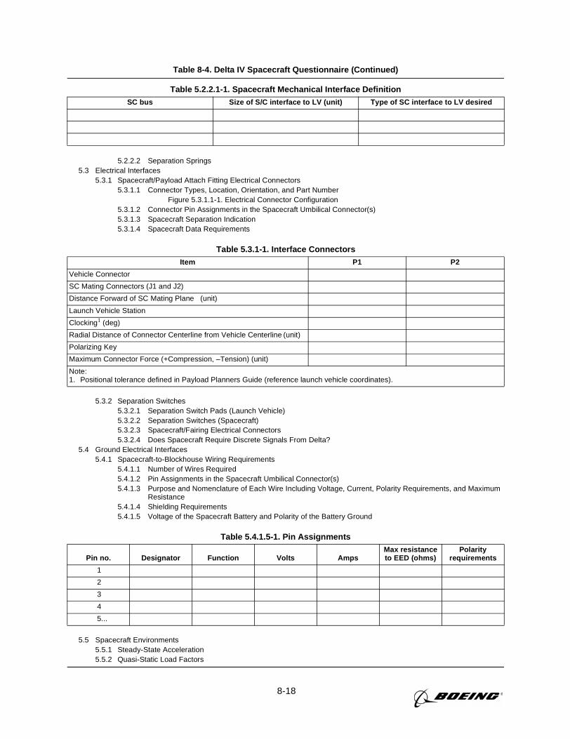
8-18
Table 8-4. Delta IV Spacecraft Questionnaire (Continued)
5.2.2.2 Separation Springs5.3 Electrical Interfaces
5.3.1 Spacecraft/Payload Attach Fitting Electrical Connectors5.3.1.1 Connector Types, Location, Orientation, and Part Number
Figure 5.3.1.1-1. Electrical Connector Configuration5.3.1.2 Connector Pin Assignments in the Spacecraft Umbilical Connector(s)5.3.1.3 Spacecraft Separation Indication5.3.1.4 Spacecraft Data Requirements
5.3.2 Separation Switches5.3.2.1 Separation Switch Pads (Launch Vehicle)5.3.2.2 Separation Switches (Spacecraft)5.3.2.3 Spacecraft/Fairing Electrical Connectors5.3.2.4 Does Spacecraft Require Discrete Signals From Delta?
5.4 Ground Electrical Interfaces5.4.1 Spacecraft-to-Blockhouse Wiring Requirements
5.4.1.1 Number of Wires Required5.4.1.2 Pin Assignments in the Spacecraft Umbilical Connector(s)5.4.1.3 Purpose and Nomenclature of Each Wire Including Voltage, Current, Polarity Requirements, and Maximum
Resistance5.4.1.4 Shielding Requirements5.4.1.5 Voltage of the Spacecraft Battery and Polarity of the Battery Ground
5.5 Spacecraft Environments5.5.1 Steady-State Acceleration5.5.2 Quasi-Static Load Factors
Table 5.2.2.1-1. Spacecraft Mechanical Interface DefinitionSC bus Size of S/C interface to LV (unit) Type of SC interface to LV desired
Table 5.3.1-1. Interface ConnectorsItem P1 P2
Vehicle Connector
SC Mating Connectors (J1 and J2)
Distance Forward of SC Mating Plane (unit)
Launch Vehicle Station
Clocking1 (deg)
Radial Distance of Connector Centerline from Vehicle Centerline (unit)
Polarizing Key
Maximum Connector Force (+Compression, –Tension) (unit)
Note:1. Positional tolerance defined in Payload Planners Guide (reference launch vehicle coordinates).
Table 5.4.1.5-1. Pin Assignments
Pin no. Designator Function Volts AmpsMax resistanceto EED (ohms)
Polarityrequirements
1
2
3
4
5...
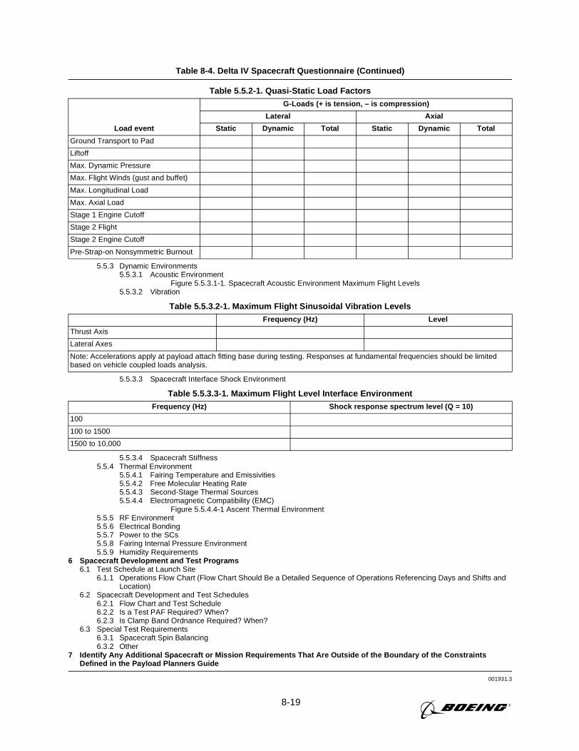
8-19
Table 8-4. Delta IV Spacecraft Questionnaire (Continued)
5.5.3 Dynamic Environments5.5.3.1 Acoustic Environment
Figure 5.5.3.1-1. Spacecraft Acoustic Environment Maximum Flight Levels5.5.3.2 Vibration
5.5.3.3 Spacecraft Interface Shock Environment
5.5.3.4 Spacecraft Stiffness5.5.4 Thermal Environment
5.5.4.1 Fairing Temperature and Emissivities5.5.4.2 Free Molecular Heating Rate5.5.4.3 Second-Stage Thermal Sources5.5.4.4 Electromagnetic Compatibility (EMC)
Figure 5.5.4.4-1 Ascent Thermal Environment5.5.5 RF Environment5.5.6 Electrical Bonding5.5.7 Power to the SCs5.5.8 Fairing Internal Pressure Environment5.5.9 Humidity Requirements
6 Spacecraft Development and Test Programs6.1 Test Schedule at Launch Site
6.1.1 Operations Flow Chart (Flow Chart Should Be a Detailed Sequence of Operations Referencing Days and Shifts andLocation)
6.2 Spacecraft Development and Test Schedules6.2.1 Flow Chart and Test Schedule6.2.2 Is a Test PAF Required? When?6.2.3 Is Clamp Band Ordnance Required? When?
6.3 Special Test Requirements6.3.1 Spacecraft Spin Balancing6.3.2 Other
7 Identify Any Additional Spacecraft or Mission Requirements That Are Outside of the Boundary of the ConstraintsDefined in the Payload Planners Guide
001931.3
Table 5.5.2-1. Quasi-Static Load Factors
Load event
G-Loads (+ is tension, – is compression)
Lateral Axial
Static Dynamic Total Static Dynamic Total
Ground Transport to Pad
Liftoff
Max. Dynamic Pressure
Max. Flight Winds (gust and buffet)
Max. Longitudinal Load
Max. Axial Load
Stage 1 Engine Cutoff
Stage 2 Flight
Stage 2 Engine Cutoff
Pre-Strap-on Nonsymmetric Burnout
Table 5.5.3.2-1. Maximum Flight Sinusoidal Vibration LevelsFrequency (Hz) Level
Thrust Axis
Lateral Axes
Note: Accelerations apply at payload attach fitting base during testing. Responses at fundamental frequencies should be limitedbased on vehicle coupled loads analysis.
Table 5.5.3.3-1. Maximum Flight Level Interface EnvironmentFrequency (Hz) Shock response spectrum level (Q = 10)
100
100 to 1500
1500 to 10,000
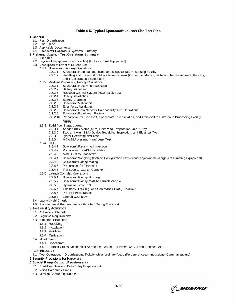
8-20
Table 8-5. Typical Spacecraft Launch-Site Test Plan
1 General1.1 Plan Organization1.2 Plan Scope1.3 Applicable Documents1.4 Spacecraft Hazardous Systems Summary
2 Prelaunch/Launch Test Operations Summary2.1 Schedule2.2 Layout of Equipment (Each Facility) (Including Test Equipment)2.3 Description of Event at Launch Site
2.3.1 Spacecraft Delivery Operations2.3.1.1 Spacecraft Removal and Transport to Spacecraft Processing Facility2.3.1.2 Handling and Transport of Miscellaneous Items (Ordnance, Motors, Batteries, Test Equipment, Handling
and Transportation Equipment)2.3.2 Payload Processing Facility Operations
2.3.2.1 Spacecraft Receiving Inspection2.3.2.2 Battery Inspection2.3.2.3 Reaction Control System (RCS) Leak Test2.3.2.4 Battery Installation2.3.2.5 Battery Charging2.3.2.6 Spacecraft Validation2.3.2.7 Solar Array Validation2.3.2.8 Spacecraft/Data Network Compatibility Test Operations2.3.2.9 Spacecraft Readiness Review2.3.2.10 Preparation for Transport, Spacecraft Encapsulation, and Transport to Hazardous Processing Facility
(HPF)2.3.3 Solid Fuel Storage Area
2.3.3.1 Apogee Kick Motor (AKM) Receiving, Preparation, and X-Ray2.3.3.2 Safe and Arm (S&A) Device Receiving, Inspection, and Electrical Test2.3.3.3 Igniter Receiving and Test2.3.3.4 AKM/S&A Assembly and Leak Test
2.3.4 HPF2.3.4.1 Spacecraft Receiving Inspection2.3.4.2 Preparation for AKM Installation2.3.4.3 Mate AKM to Spacecraft2.3.4.4 Spacecraft Weighing (Include Configuration Sketch and Approximate Weights of Handling Equipment)2.3.4.5 Spacecraft/Fairing Mating2.3.4.6 Preparation for Transport2.3.4.7 Transport to Launch Complex
2.3.5 Launch Complex Operations2.3.5.1 Spacecraft/Fairing Hoisting2.3.5.2 Spacecraft/Fairing Mate to Launch Vehicle2.3.5.3 Hydrazine Leak Test2.3.5.4 Telemetry, Tracking, and Command (TT&C) Checkout2.3.5.5 Preflight Preparations2.3.5.6 Launch Countdown
2.4 Launch/Hold Criteria2.5 Environmental Requirement for Facilities During Transport
3 Test Facility Activation3.1 Activation Schedule3.2 Logistics Requirements3.3 Equipment Handling
3.3.1 Receiving3.3.2 Installation3.3.3 Validation3.3.4 Calibration
3.4 Maintenance3.4.1 Spacecraft3.4.2 Launch-Critical Mechanical Aerospace Ground Equipment (AGE) and Electrical AGE
4 Administration4.1 Test Operations—Organizational Relationships and Interfaces (Personnel Accommodations, Communications)
5 Security Provisions for Hardware6 Special Range-Support Requirements
6.1 Real-Time Tracking Data Relay Requirements6.2 Voice Communications6.3 Mission Control Operations
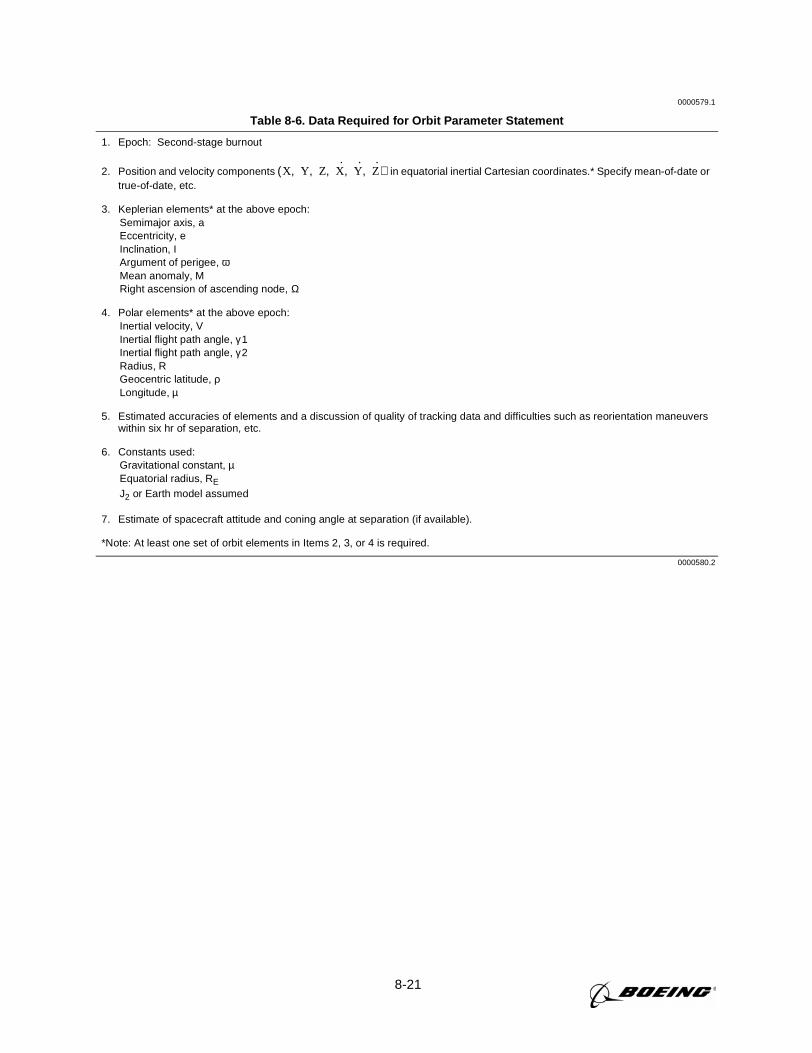
8-21
0000579.1
Table 8-6. Data Required for Orbit Parameter Statement
1. Epoch: Second-stage burnout
2. Position and velocity components in equatorial inertial Cartesian coordinates.* Specify mean-of-date ortrue-of-date, etc.
3. Keplerian elements* at the above epoch:Semimajor axis, aEccentricity, eInclination, IArgument of perigee, ωMean anomaly, MRight ascension of ascending node, Ω
4. Polar elements* at the above epoch:Inertial velocity, VInertial flight path angle, γ 1Inertial flight path angle, γ 2Radius, RGeocentric latitude, ρLongitude, µ
5. Estimated accuracies of elements and a discussion of quality of tracking data and difficulties such as reorientation maneuverswithin six hr of separation, etc.
6. Constants used:Gravitational constant, µEquatorial radius, RE
J2 or Earth model assumed
7. Estimate of spacecraft attitude and coning angle at separation (if available).
*Note: At least one set of orbit elements in Items 2, 3, or 4 is required.
0000580.2
X Y Z X·
Y·
Z·
, , , , ,( )
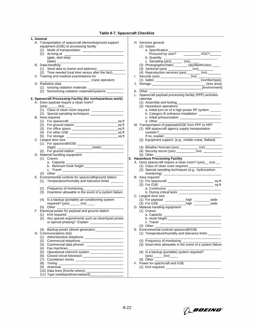
8-22
Table 8-7. Spacecraft Checklist1. General
A. Transportation of spacecraft elements/ground supportequipment (GSE) to processing facility(1) Mode of transportation ______________________(2) Arriving at ________________________________
(gate, skid strip)(date) ____________________________________
B. Data-handling(1) Send data to (name and address) _______________(2) Time needed (real time versus after the fact)_______
C. Training and medical examinations for___________________________ crane operators
D. Radiation data(1) Ionizing radiation materials ___________________(2) Nonionizing radiation materials/systems _________
_________________________________________2. Spacecraft Processing Facility (for nonhazardous work)
A. Does payload require a clean room?(yes) _____ (no) ____(1) Class of clean room required _________________(2) Special sampling techniques __________________
B. Area required(1) For spacecraft __________________________sq ft(2) For ground station _______________________sq ft(3) For office space _________________________sq ft(4) For other GSE __________________________sq ft(5) For storage ____________________________ sq ft
C. Largest door size(1) For spacecraft/GSE _________________________
(high) ___________________(wide) ____________(2) For ground station __________________________
D. Material-handling equipment(1) Cranes
a. Capacity _______________________________b. Minimum hook height _____________________c. Travel _________________________________
(2) Other ____________________________________E. Environmental controls for spacecraft/ground station
(1) Temperature/humidity and tolerance limits ________________________________________________
(2) Frequency of monitoring______________________(3) Downtime allowable in the event of a system failure
__________________________________________(4) Is a backup (portable) air-conditioning system
required? (yes) _____ (no) ____(5) Other ____________________________________
F. Electrical power for payload and ground station(1) kVA required ______________________________(2) Any special requirements such as clean/quiet power,
or special phasing? Explain ___________________________________________________________
(3) Backup power (diesel generator) _______________G. Communications (list)
(1) Administrative telephone _____________________(2) Commercial telephone _______________________(3) Commercial data phones ____________________(4) Fax machines ______________________________(5) Operational intercom system __________________(6) Closed-circuit television ______________________(7) Countdown clocks __________________________(8) Timing ___________________________________(9) Antennas _________________________________(10) Data lines (from/to where) ____________________(11) Type (wideband/narrowband)__________________
H. Services general(1) Gases
a. Specification_____________________________Procured by user? _________ KSC?______
b. Quantity _____________________________c. Sampling (yes)______ (no)_____
(2) Photographs/Video _______ (qty/B&W/color) ____(3) Janitorial (yes) _____________ (no)________(4) Reproduction services (yes) _______ (no) _______
I. Security (yes) ________________ (no) _____________(1) Safes ________________________ (number/type)
J. Storage _____________________________ (size area)__________________________________(environment)
K. Other _____________________________________L. Spacecraft payload processing facility (PPF) activities
calendar(1) Assembly and testing________________________(2) Hazardous operations
a. Initial turn-on of a high-power RF system ______b. Category B ordnance installation ____________c. Initial pressurization ______________________d. Other __________________________________
M. Transportation of payloads/GSE from PPF to HPF(1) Will spacecraft agency supply transportation
canister?__________________________________If no, explain _______________________________
(2) Equipment support, (e.g., mobile crane, flatbed)__________________________________________
(3) Weather forecast (yes) __________ (no) _________(4) Security escort (yes) __________ (no) __________(5) Other _____________________________________
3. Hazardous Processing FacilityA. Does spacecraft require a clean room? (yes)__ (no) __
(1) Class of clean room required __________________(2) Special sampling techniques (e.g., hydrocarbon
monitoring) _______________________________B. Area required
(1) For spacecraft _________________________ sq ft(2) For GSE _____________________________ sq ft
a. Continuous _____________________________b. During critical tests _______________________
C. Largest door size(1) For payload ___________high _________wide(2) For GSE ______________high _________wide
D. Material handling equipment(1) Cranes
a. Capacity _______________________________b. Hook height _____________________________c. Travel _________________________________
(2) Other ____________________________________E. Environmental controls spacecraft/GSE
(1) Temperature/humidity and tolerance limits ________________________________________________
(2) Frequency of monitoring _____________________(3) Down-time allowable in the event of a system failure
_________________________________________(4) Is a backup (portable) system required?
(yes) _____ (no) ____(5) Other ____________________________________
F. Power for spacecraft and GSE(1) kVA required ______________________________
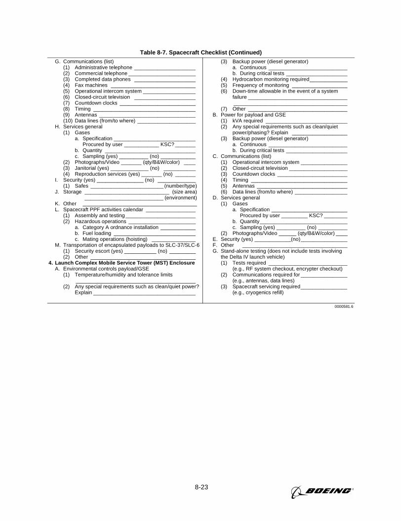
8-23
Table 8-7. Spacecraft Checklist (Continued)G. Communications (list)
(1) Administrative telephone _____________________(2) Commercial telephone _______________________(3) Completed data phones _____________________(4) Fax machines _____________________________(5) Operational intercom system __________________(6) Closed-circuit television _____________________(7) Countdown clocks __________________________(8) Timing ___________________________________(9) Antennas _________________________________(10) Data lines (from/to where) ____________________
H. Services general(1) Gases
a. Specification ____________________________Procured by user ____________ KSC? _______
b. Quantity _______________________________c. Sampling (yes) __________ (no) ____________
(2) Photographs/Video _______ (qty/B&W/color) ____(3) Janitorial (yes) _____________ (no) ___________(4) Reproduction services (yes) _______ (no) _______
I. Security (yes) ________________ (no) _____________(1) Safes _________________________ (number/type)
J. Storage _____________________________ (size area)___________________________ (environment)
K. Other _____________________________L. Spacecraft PPF activities calendar _________________
(1) Assembly and testing ________________________(2) Hazardous operations _______________________
a. Category A ordnance installation ____________b. Fuel loading ____________________________c. Mating operations (hoisting) _______________
M. Transportation of encapsulated payloads to SLC-37/SLC-6(1) Security escort (yes) ___________ (no) _________(2) Other ____________________________________
4. Launch Complex Mobile Service Tower (MST) EnclosureA. Environmental controls payload/GSE
(1) Temperature/humidity and tolerance limits_________________________________________
(2) Any special requirements such as clean/quiet power?Explain ___________________________________
(3) Backup power (diesel generator)a. Continuous ___________________________b. During critical tests _____________________
(4) Hydrocarbon monitoring required_____________(5) Frequency of monitoring ___________________(6) Down-time allowable in the event of a system
failure _________________________________________________________________________
(7) Other __________________________________B. Power for payload and GSE
(1) kVA required ____________________________(2) Any special requirements such as clean/quiet
power/phasing? Explain ___________________(3) Backup power (diesel generator)
a. Continuous ___________________________b. During critical tests _____________________
C. Communications (list)(1) Operational intercom system ________________(2) Closed-circuit television ____________________(3) Countdown clocks ________________________(4) Timing _________________________________(5) Antennas _______________________________(6) Data lines (from/to where) __________________
D. Services general(1) Gases
a. Specification __________________________Procured by user _________ KSC? ________
b. Quantity______________________________c. Sampling (yes) __________ (no) __________
(2) Photographs/Video ______ (qty/B&W/color) ____E. Security (yes) ____________ (no)________________F. Other ____________________________________G. Stand-alone testing (does not include tests involving
the Delta IV launch vehicle)(1) Tests required ___________________________
(e.g., RF system checkout, encrypter checkout)(2) Communications required for ________________
(e.g., antennas, data lines)(3) Spacecraft servicing required________________
(e.g., cryogenics refill)
0000581.6
9-1
Section 9
SAFETY
This section discusses the safety requirements that govern a payload to be launched by a
Delta IV launch vehicle from Cape Canaveral Air Station (CCAS), Florida, or Vandenberg Air
Force Base (VAFB), California. This section provides safety requirements guidance for pay-
load processing operations conducted at Space Launch Complex 37 A/B (CCAS) or Space
Launch Complex 6 (VAFB).
Payload prelaunch operations may be conducted at Cape Canaveral Air Station, Florida; at
Astrotech in Titusville, Florida; Astrotech, Vandenberg Air Force Base, California; or at Space-
port Systems International, Vandenberg Air Force Base, California, by arrangement with the
appropriate agencies. Payload operations conducted at Astrotech facilities shall be conducted in
accordance with Astrotech ground safety polices. Payload operations conducted at Spaceport
Systems International facilities shall be conducted in accordance with Spaceport Systems interna-
tional ground safety polices.
Payload transportation operations conducted on public highways shall be conducted in accor-
dance with Code of Federal Regulations (CFR), Title 49, Department of Transportation, Transpor-
tation of Hazardous Materials.
The USAF 30th and 45th Space Wings are responsible for overall range (ground/flight) safety
at CCAS and VAFB, respectively, and are primarily concerned with payload flight and public
safety concerns associated with cryogenic, solid fuel, hypergolic fuel, or early flight termination
system (FTS) action catastrophic hazards. Payload operations conducted under the jurisdiction of
the Eastern and Western Range shall be in accordance with the Eastern and Western Range
(EWR) 127-1 Range Safety Requirements.
The Federal Aviation Administration (FAA)/Associate Administrator for Commercial Safety
Transportation (AST) is responsible for the licensing of commercial space launches and permit-
ting the operations of commercial launch sites. Mission-specific launch license processing shall
be the responsibility of Boeing Delta Launch Services in accordance with Code of Federal Regu-
lations, Title 14, Aeronautics and Space, Parts 400-499, Commercial Space Transportation.
Delta IV payload launch complex operations are conducted at Space Launch Complex 37 A/B
(CCAS) and Space Launch Complex 6 (VAFB) in accordance with the applicable Operations
Safety Plan and the Delta IV EWR 127-1 Range Safety Requirements (Tailored), MDC 99H1112.
9.1 REQUIREMENTS
The payload organization shall have a system safety program to effectively:
A. Identify and adequately describe all hazardous systems, assess associated mishap risks/mit-
igation measures, reduce mishap risks to acceptable levels, verify/document/track identified risks
9-2
using a risk-management-process to support preparation of a mission-unique missile system pre-
launch safety package (MSPSP) and payload safety review process in accordance with Delta IV
EWR 127-1 (T), Appendix 3A and Appendix C “Payload Safety Requirements.”
B. Support an assessment to determine if a flight termination system is required.
C. Identify to Delta Launch Services any potential Delta IV EWR 127-1 (T)—MDC 99H1112,
tailoring requests prior to the mission orientation briefing.
D. Identify to Delta Launch Services any potential Delta IV EWR 127-1 (T)—MDC 99H1112,
noncompliance requests prior to the mission orientation briefing.
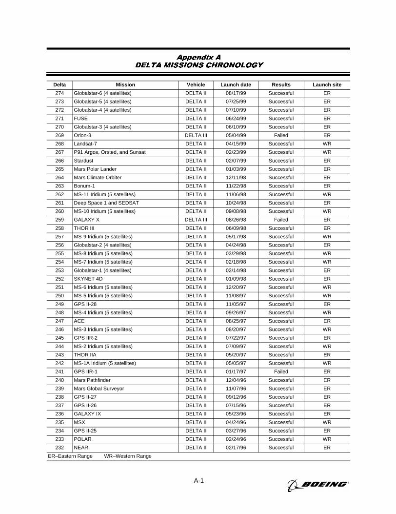
A-1
Appendix ADELTA MISSIONS CHRONOLOGY
Delta Mission Vehicle Launch date Results Launch site
274 Globalstar-6 (4 satellites) DELTA II 08/17/99 Successful ER
273 Globalstar-5 (4 satellites) DELTA II 07/25/99 Successful ER
272 Globalstar-4 (4 satellites) DELTA II 07/10/99 Successful ER
271 FUSE DELTA II 06/24/99 Successful ER
270 Globalstar-3 (4 satellites) DELTA II 06/10/99 Successful ER
269 Orion-3 DELTA III 05/04/99 Failed ER
268 Landsat-7 DELTA II 04/15/99 Successful WR
267 P91 Argos, Orsted, and Sunsat DELTA II 02/23/99 Successful WR
266 Stardust DELTA II 02/07/99 Successful ER
265 Mars Polar Lander DELTA II 01/03/99 Successful ER
264 Mars Climate Orbiter DELTA II 12/11/98 Successful ER
263 Bonum-1 DELTA II 11/22/98 Successful ER
262 MS-11 Iridium (5 satellites) DELTA II 11/06/98 Successful WR
261 Deep Space 1 and SEDSAT DELTA II 10/24/98 Successful ER
260 MS-10 Iridium (5 satellites) DELTA II 09/08/98 Successful WR
259 GALAXY X DELTA III 08/26/98 Failed ER
258 THOR III DELTA II 06/09/98 Successful ER
257 MS-9 Iridium (5 satellites) DELTA II 05/17/98 Successful WR
256 Globalstar-2 (4 satellites) DELTA II 04/24/98 Successful ER
255 MS-8 Iridium (5 satellites) DELTA II 03/29/98 Successful WR
254 MS-7 Iridium (5 satellites) DELTA II 02/18/98 Successful WR
253 Globalstar-1 (4 satellites) DELTA II 02/14/98 Successful ER
252 SKYNET 4D DELTA II 01/09/98 Successful ER
251 MS-6 Iridium (5 satellites) DELTA II 12/20/97 Successful WR
250 MS-5 Iridium (5 satellites) DELTA II 11/08/97 Successful WR
249 GPS II-28 DELTA II 11/05/97 Successful ER
248 MS-4 Iridium (5 satellites) DELTA II 09/26/97 Successful WR
247 ACE DELTA II 08/25/97 Successful ER
246 MS-3 Iridium (5 satellites) DELTA II 08/20/97 Successful WR
245 GPS IIR-2 DELTA II 07/22/97 Successful ER
244 MS-2 Iridium (5 satellites) DELTA II 07/09/97 Successful WR
243 THOR IIA DELTA II 05/20/97 Successful ER
242 MS-1A Iridium (5 satellites) DELTA II 05/05/97 Successful WR
241 GPS IIR-1 DELTA II 01/17/97 Failed ER
240 Mars Pathfinder DELTA II 12/04/96 Successful ER
239 Mars Global Surveyor DELTA II 11/07/96 Successful ER
238 GPS II-27 DELTA II 09/12/96 Successful ER
237 GPS II-26 DELTA II 07/15/96 Successful ER
236 GALAXY IX DELTA II 05/23/96 Successful ER
235 MSX DELTA II 04/24/96 Successful WR
234 GPS II-25 DELTA II 03/27/96 Successful ER
233 POLAR DELTA II 02/24/96 Successful WR
232 NEAR DELTA II 02/17/96 Successful ER
ER–Eastern Range WR–Western Range
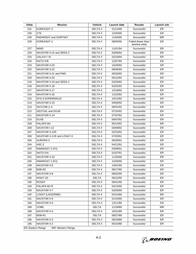
A-2
231 KOREASAT-2 DELTA II 01/14/96 Successful ER
230 XTE DELTA II 12/30/95 Successful ER
229 RADARSAT and SURFSAT DELTA II 11/04/95 Successful WR
228 KOREASAT-1 DELTA II 08/05/95 Failed (lower thandesired orbit)
ER
227 WIND DELTA II 11/01/94 Successful ER
226 NAVSTAR II-24 and SEDS-2 DELTA II 03/09/94 Successful ER
225 GALAXY I-R DELTA II 02/19/94 Successful ER
224 NATO IVB DELTA II 12/07/93 Successful ER
223 NAVSTAR II-23 DELTA II 10/26/93 Successful ER
222 NAVSTAR II-22 DELTA II 08/30/93 Successful ER
221 NAVSTAR II-21 and PMG DELTA II 06/26/93 Successful ER
220 NAVSTAR II-20 DELTA II 05/12/93 Successful ER
219 NAVSTAR II-19 and SEDS-1 DELTA II 03/29/93 Successful ER
218 NAVSTAR II-18 DELTA II 02/02/93 Successful ER
217 NAVSTAR II-17 DELTA II 12/18/92 Successful ER
216 NAVSTAR II-16 DELTA II 11/22/92 Successful ER
215 DFS-3 KOPERNIKUS DELTA II 10/12/92 Successful ER
214 NAVSTAR II-15 DELTA II 09/09/92 Successful ER
213 SATCOM C-4 DELTA II 08/31/92 Successful ER
212 GEOTAIL and DUVE DELTA II 07/24/92 Successful ER
211 NAVSTAR II-14 DELTA II 07/07/92 Successful ER
210 EUVE DELTA II 06/07/92 Successful ER
209 PALAPA B4 DELTA II 05/13/92 Successful ER
208 NAVSTAR I-13 DELTA II 04/09/92 Successful ER
207 NAVSTAR II-12R DELTA II 02/23/92 Successful ER
206 NAVSTAR II-11R and LOSAT-X DELTA II 07/03/91 Successful ER
205 AURORA II DELTA II 05/29/91 Successful ER
204 ASC-2 DELTA II 04/12/91 Successful ER
203 INMARSAT 2 (F2) DELTA II 03/08/91 Successful ER
202 NATO-IVA DELTA II 01/07/91 Successful ER
201 NAVSTAR II-10 DELTA II 11/26/90 Successful ER
200 INMARSAT 2 (F2) DELTA II 10/30/90 Successful ER
199 NAVSTAR II-9 DELTA II 10/01/90 Successful ER
198 BSB-R2 DELTA II 08/17/90 Successful ER
197 NAVSTAR II-8 DELTA II 08/02/90 Successful ER
196 INSAT-1D DELTA 06/12/90 Successful ER
195 ROSAT DELTA II 06/01/90 Successful ER
194 PALAPA B2-R DELTA II 04/13/90 Successful ER
193 NAVSTAR II-7 DELTA II 03/25/90 Successful ER
192 LOSAT (LACE/RME) DELTA II 02/14/90 Successful ER
191 NAVSTAR II-6 DELTA II 01/24/90 Successful ER
190 NAVSTAR II-5 DELTA II 12/11/89 Successful ER
189 COBE DELTA 11/18/89 Successful WR
188 NAVSTAR II-4 DELTA II 10/21/89 Successful ER
187 BSB-R1 DELTA 08/27/89 Successful ER
186 NAVSTAR II-3 DELTA II 08/18/89 Successful ER
185 NAVSTAR II-2 DELTA II 06/10/89 Successful ER
ER–Eastern Range WR–Western Range
Delta Mission Vehicle Launch date Results Launch site
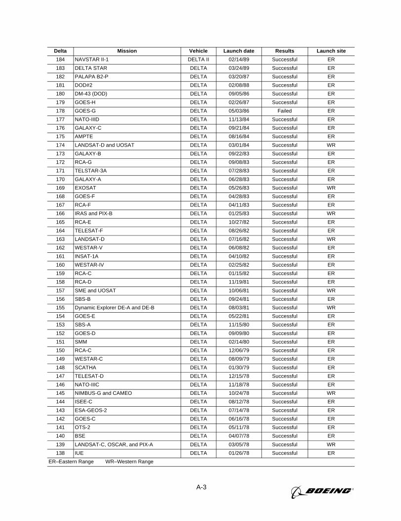
A-3
184 NAVSTAR II-1 DELTA II 02/14/89 Successful ER
183 DELTA STAR DELTA 03/24/89 Successful ER
182 PALAPA B2-P DELTA 03/20/87 Successful ER
181 DOD#2 DELTA 02/08/88 Successful ER
180 DM-43 (DOD) DELTA 09/05/86 Successful ER
179 GOES-H DELTA 02/26/87 Successful ER
178 GOES-G DELTA 05/03/86 Failed ER
177 NATO-IIID DELTA 11/13/84 Successful ER
176 GALAXY-C DELTA 09/21/84 Successful ER
175 AMPTE DELTA 08/16/84 Successful ER
174 LANDSAT-D and UOSAT DELTA 03/01/84 Successful WR
173 GALAXY-B DELTA 09/22/83 Successful ER
172 RCA-G DELTA 09/08/83 Successful ER
171 TELSTAR-3A DELTA 07/28/83 Successful ER
170 GALAXY-A DELTA 06/28/83 Successful ER
169 EXOSAT DELTA 05/26/83 Successful WR
168 GOES-F DELTA 04/28/83 Successful ER
167 RCA-F DELTA 04/11/83 Successful ER
166 IRAS and PIX-B DELTA 01/25/83 Successful WR
165 RCA-E DELTA 10/27/82 Successful ER
164 TELESAT-F DELTA 08/26/82 Successful ER
163 LANDSAT-D DELTA 07/16/82 Successful WR
162 WESTAR-V DELTA 06/08/82 Successful ER
161 INSAT-1A DELTA 04/10/82 Successful ER
160 WESTAR-IV DELTA 02/25/82 Successful ER
159 RCA-C DELTA 01/15/82 Successful ER
158 RCA-D DELTA 11/19/81 Successful ER
157 SME and UOSAT DELTA 10/06/81 Successful WR
156 SBS-B DELTA 09/24/81 Successful ER
155 Dynamic Explorer DE-A and DE-B DELTA 08/03/81 Successful WR
154 GOES-E DELTA 05/22/81 Successful ER
153 SBS-A DELTA 11/15/80 Successful ER
152 GOES-D DELTA 09/09/80 Successful ER
151 SMM DELTA 02/14/80 Successful ER
150 RCA-C DELTA 12/06/79 Successful ER
149 WESTAR-C DELTA 08/09/79 Successful ER
148 SCATHA DELTA 01/30/79 Successful ER
147 TELESAT-D DELTA 12/15/78 Successful ER
146 NATO-IIIC DELTA 11/18/78 Successful ER
145 NIMBUS-G and CAMEO DELTA 10/24/78 Successful WR
144 ISEE-C DELTA 08/12/78 Successful ER
143 ESA-GEOS-2 DELTA 07/14/78 Successful ER
142 GOES-C DELTA 06/16/78 Successful ER
141 OTS-2 DELTA 05/11/78 Successful ER
140 BSE DELTA 04/07/78 Successful ER
139 LANDSAT-C, OSCAR, and PIX-A DELTA 03/05/78 Successful WR
138 IUE DELTA 01/26/78 Successful ER
ER–Eastern Range WR–Western Range
Delta Mission Vehicle Launch date Results Launch site
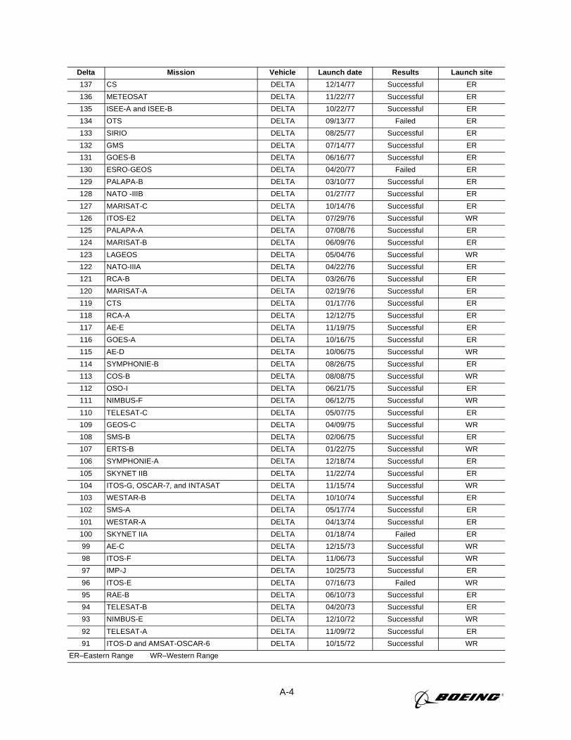
A-4
137 CS DELTA 12/14/77 Successful ER
136 METEOSAT DELTA 11/22/77 Successful ER
135 ISEE-A and ISEE-B DELTA 10/22/77 Successful ER
134 OTS DELTA 09/13/77 Failed ER
133 SIRIO DELTA 08/25/77 Successful ER
132 GMS DELTA 07/14/77 Successful ER
131 GOES-B DELTA 06/16/77 Successful ER
130 ESRO-GEOS DELTA 04/20/77 Failed ER
129 PALAPA-B DELTA 03/10/77 Successful ER
128 NATO -IIIB DELTA 01/27/77 Successful ER
127 MARISAT-C DELTA 10/14/76 Successful ER
126 ITOS-E2 DELTA 07/29/76 Successful WR
125 PALAPA-A DELTA 07/08/76 Successful ER
124 MARISAT-B DELTA 06/09/76 Successful ER
123 LAGEOS DELTA 05/04/76 Successful WR
122 NATO-IIIA DELTA 04/22/76 Successful ER
121 RCA-B DELTA 03/26/76 Successful ER
120 MARISAT-A DELTA 02/19/76 Successful ER
119 CTS DELTA 01/17/76 Successful ER
118 RCA-A DELTA 12/12/75 Successful ER
117 AE-E DELTA 11/19/75 Successful ER
116 GOES-A DELTA 10/16/75 Successful ER
115 AE-D DELTA 10/06/75 Successful WR
114 SYMPHONIE-B DELTA 08/26/75 Successful ER
113 COS-B DELTA 08/08/75 Successful WR
112 OSO-I DELTA 06/21/75 Successful ER
111 NIMBUS-F DELTA 06/12/75 Successful WR
110 TELESAT-C DELTA 05/07/75 Successful ER
109 GEOS-C DELTA 04/09/75 Successful WR
108 SMS-B DELTA 02/06/75 Successful ER
107 ERTS-B DELTA 01/22/75 Successful WR
106 SYMPHONIE-A DELTA 12/18/74 Successful ER
105 SKYNET IIB DELTA 11/22/74 Successful ER
104 ITOS-G, OSCAR-7, and INTASAT DELTA 11/15/74 Successful WR
103 WESTAR-B DELTA 10/10/74 Successful ER
102 SMS-A DELTA 05/17/74 Successful ER
101 WESTAR-A DELTA 04/13/74 Successful ER
100 SKYNET IIA DELTA 01/18/74 Failed ER
99 AE-C DELTA 12/15/73 Successful WR
98 ITOS-F DELTA 11/06/73 Successful WR
97 IMP-J DELTA 10/25/73 Successful ER
96 ITOS-E DELTA 07/16/73 Failed WR
95 RAE-B DELTA 06/10/73 Successful ER
94 TELESAT-B DELTA 04/20/73 Successful ER
93 NIMBUS-E DELTA 12/10/72 Successful WR
92 TELESAT-A DELTA 11/09/72 Successful ER
91 ITOS-D and AMSAT-OSCAR-6 DELTA 10/15/72 Successful WR
ER–Eastern Range WR–Western Range
Delta Mission Vehicle Launch date Results Launch site
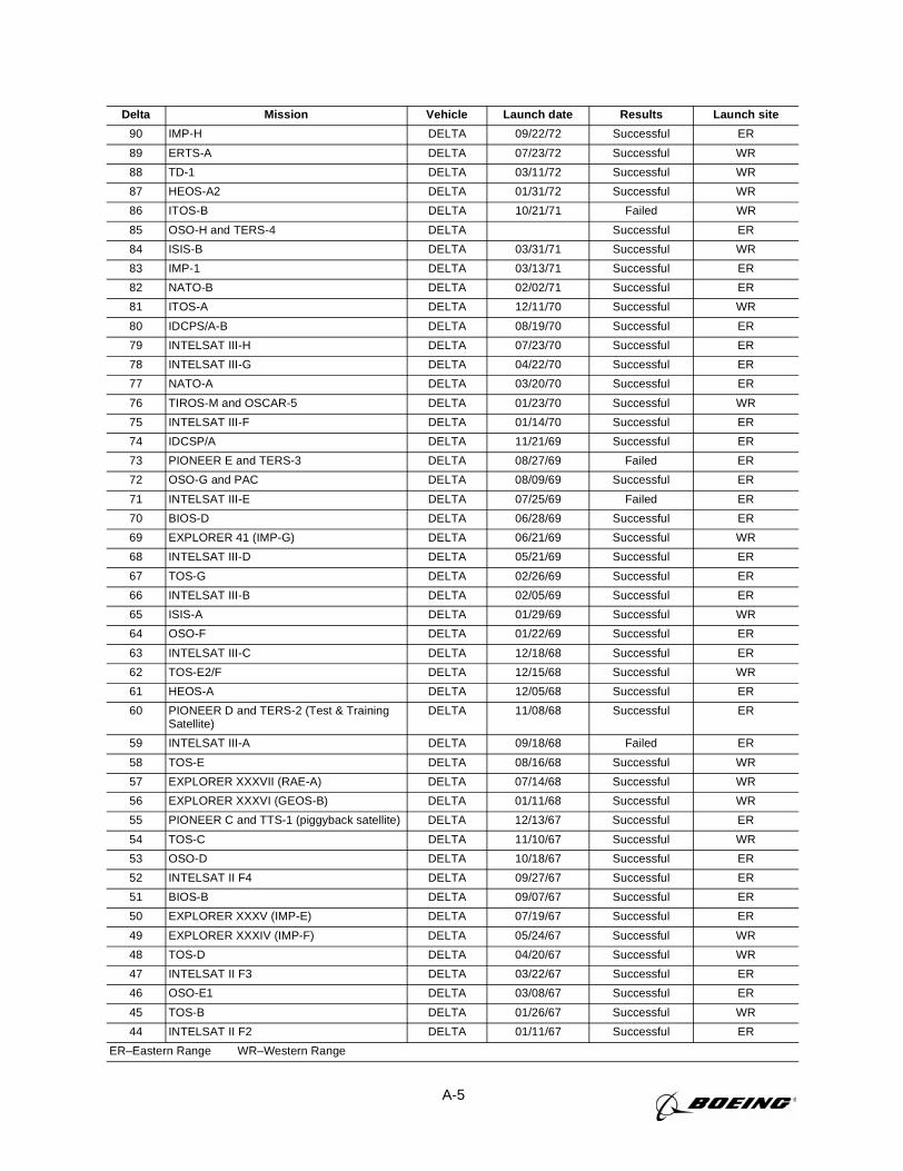
A-5
90 IMP-H DELTA 09/22/72 Successful ER
89 ERTS-A DELTA 07/23/72 Successful WR
88 TD-1 DELTA 03/11/72 Successful WR
87 HEOS-A2 DELTA 01/31/72 Successful WR
86 ITOS-B DELTA 10/21/71 Failed WR
85 OSO-H and TERS-4 DELTA Successful ER
84 ISIS-B DELTA 03/31/71 Successful WR
83 IMP-1 DELTA 03/13/71 Successful ER
82 NATO-B DELTA 02/02/71 Successful ER
81 ITOS-A DELTA 12/11/70 Successful WR
80 IDCPS/A-B DELTA 08/19/70 Successful ER
79 INTELSAT III-H DELTA 07/23/70 Successful ER
78 INTELSAT III-G DELTA 04/22/70 Successful ER
77 NATO-A DELTA 03/20/70 Successful ER
76 TIROS-M and OSCAR-5 DELTA 01/23/70 Successful WR
75 INTELSAT III-F DELTA 01/14/70 Successful ER
74 IDCSP/A DELTA 11/21/69 Successful ER
73 PIONEER E and TERS-3 DELTA 08/27/69 Failed ER
72 OSO-G and PAC DELTA 08/09/69 Successful ER
71 INTELSAT III-E DELTA 07/25/69 Failed ER
70 BIOS-D DELTA 06/28/69 Successful ER
69 EXPLORER 41 (IMP-G) DELTA 06/21/69 Successful WR
68 INTELSAT III-D DELTA 05/21/69 Successful ER
67 TOS-G DELTA 02/26/69 Successful ER
66 INTELSAT III-B DELTA 02/05/69 Successful ER
65 ISIS-A DELTA 01/29/69 Successful WR
64 OSO-F DELTA 01/22/69 Successful ER
63 INTELSAT III-C DELTA 12/18/68 Successful ER
62 TOS-E2/F DELTA 12/15/68 Successful WR
61 HEOS-A DELTA 12/05/68 Successful ER
60 PIONEER D and TERS-2 (Test & TrainingSatellite)
DELTA 11/08/68 Successful ER
59 INTELSAT III-A DELTA 09/18/68 Failed ER
58 TOS-E DELTA 08/16/68 Successful WR
57 EXPLORER XXXVII (RAE-A) DELTA 07/14/68 Successful WR
56 EXPLORER XXXVI (GEOS-B) DELTA 01/11/68 Successful WR
55 PIONEER C and TTS-1 (piggyback satellite) DELTA 12/13/67 Successful ER
54 TOS-C DELTA 11/10/67 Successful WR
53 OSO-D DELTA 10/18/67 Successful ER
52 INTELSAT II F4 DELTA 09/27/67 Successful ER
51 BIOS-B DELTA 09/07/67 Successful ER
50 EXPLORER XXXV (IMP-E) DELTA 07/19/67 Successful ER
49 EXPLORER XXXIV (IMP-F) DELTA 05/24/67 Successful WR
48 TOS-D DELTA 04/20/67 Successful WR
47 INTELSAT II F3 DELTA 03/22/67 Successful ER
46 OSO-E1 DELTA 03/08/67 Successful ER
45 TOS-B DELTA 01/26/67 Successful WR
44 INTELSAT II F2 DELTA 01/11/67 Successful ER
ER–Eastern Range WR–Western Range
Delta Mission Vehicle Launch date Results Launch site
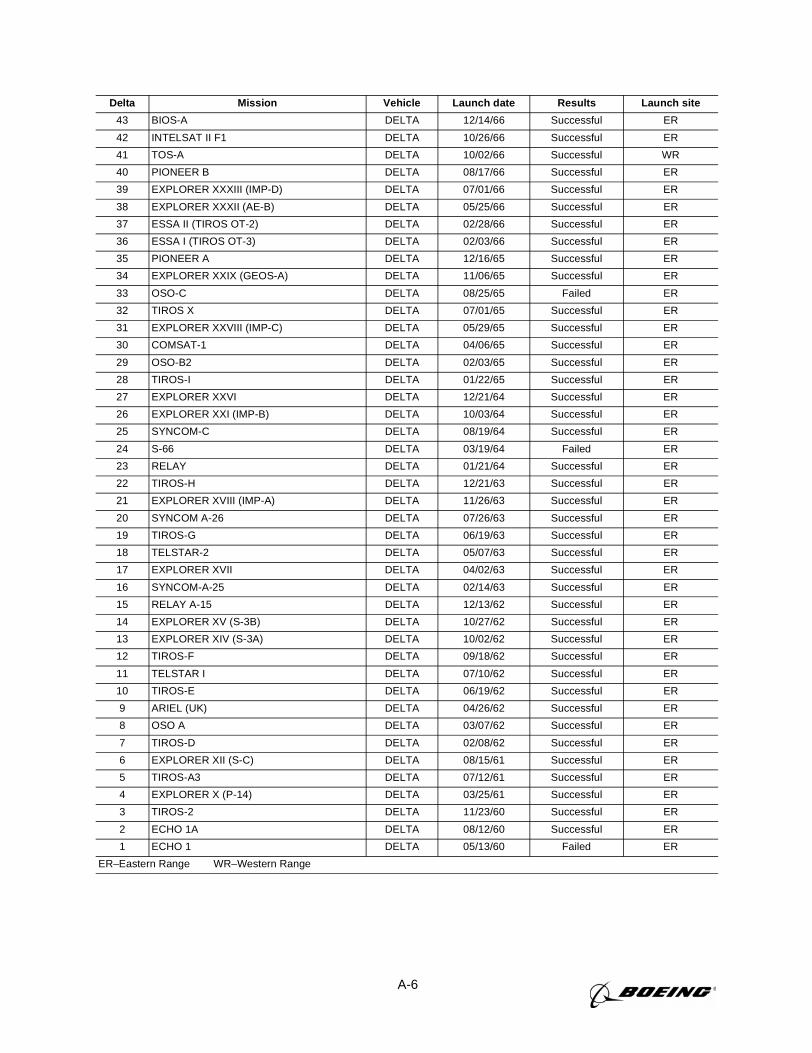
A-6
43 BIOS-A DELTA 12/14/66 Successful ER
42 INTELSAT II F1 DELTA 10/26/66 Successful ER
41 TOS-A DELTA 10/02/66 Successful WR
40 PIONEER B DELTA 08/17/66 Successful ER
39 EXPLORER XXXIII (IMP-D) DELTA 07/01/66 Successful ER
38 EXPLORER XXXII (AE-B) DELTA 05/25/66 Successful ER
37 ESSA II (TIROS OT-2) DELTA 02/28/66 Successful ER
36 ESSA I (TIROS OT-3) DELTA 02/03/66 Successful ER
35 PIONEER A DELTA 12/16/65 Successful ER
34 EXPLORER XXIX (GEOS-A) DELTA 11/06/65 Successful ER
33 OSO-C DELTA 08/25/65 Failed ER
32 TIROS X DELTA 07/01/65 Successful ER
31 EXPLORER XXVIII (IMP-C) DELTA 05/29/65 Successful ER
30 COMSAT-1 DELTA 04/06/65 Successful ER
29 OSO-B2 DELTA 02/03/65 Successful ER
28 TIROS-I DELTA 01/22/65 Successful ER
27 EXPLORER XXVI DELTA 12/21/64 Successful ER
26 EXPLORER XXI (IMP-B) DELTA 10/03/64 Successful ER
25 SYNCOM-C DELTA 08/19/64 Successful ER
24 S-66 DELTA 03/19/64 Failed ER
23 RELAY DELTA 01/21/64 Successful ER
22 TIROS-H DELTA 12/21/63 Successful ER
21 EXPLORER XVIII (IMP-A) DELTA 11/26/63 Successful ER
20 SYNCOM A-26 DELTA 07/26/63 Successful ER
19 TIROS-G DELTA 06/19/63 Successful ER
18 TELSTAR-2 DELTA 05/07/63 Successful ER
17 EXPLORER XVII DELTA 04/02/63 Successful ER
16 SYNCOM-A-25 DELTA 02/14/63 Successful ER
15 RELAY A-15 DELTA 12/13/62 Successful ER
14 EXPLORER XV (S-3B) DELTA 10/27/62 Successful ER
13 EXPLORER XIV (S-3A) DELTA 10/02/62 Successful ER
12 TIROS-F DELTA 09/18/62 Successful ER
11 TELSTAR I DELTA 07/10/62 Successful ER
10 TIROS-E DELTA 06/19/62 Successful ER
9 ARIEL (UK) DELTA 04/26/62 Successful ER
8 OSO A DELTA 03/07/62 Successful ER
7 TIROS-D DELTA 02/08/62 Successful ER
6 EXPLORER XII (S-C) DELTA 08/15/61 Successful ER
5 TIROS-A3 DELTA 07/12/61 Successful ER
4 EXPLORER X (P-14) DELTA 03/25/61 Successful ER
3 TIROS-2 DELTA 11/23/60 Successful ER
2 ECHO 1A DELTA 08/12/60 Successful ER
1 ECHO 1 DELTA 05/13/60 Failed ER
ER–Eastern Range WR–Western Range
Delta Mission Vehicle Launch date Results Launch site
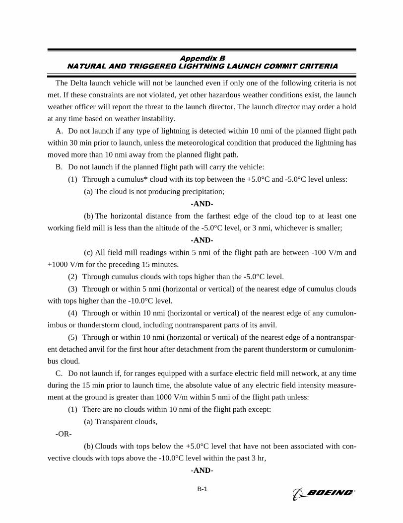
B-1
Appendix BNATURAL AND TRIGGERED LIGHTNING LAUNCH COMMIT CRITERIA
The Delta launch vehicle will not be launched even if only one of the following criteria is not
met. If these constraints are not violated, yet other hazardous weather conditions exist, the launch
weather officer will report the threat to the launch director. The launch director may order a hold
at any time based on weather instability.
A. Do not launch if any type of lightning is detected within 10 nmi of the planned flight path
within 30 min prior to launch, unless the meteorological condition that produced the lightning has
moved more than 10 nmi away from the planned flight path.
B. Do not launch if the planned flight path will carry the vehicle:
(1) Through a cumulus* cloud with its top between the +5.0°C and -5.0°C level unless:
(a) The cloud is not producing precipitation;
-AND-
(b) The horizontal distance from the farthest edge of the cloud top to at least one
working field mill is less than the altitude of the -5.0°C level, or 3 nmi, whichever is smaller;
-AND-
(c) All field mill readings within 5 nmi of the flight path are between -100 V/m and
+1000 V/m for the preceding 15 minutes.
(2) Through cumulus clouds with tops higher than the -5.0°C level.
(3) Through or within 5 nmi (horizontal or vertical) of the nearest edge of cumulus clouds
with tops higher than the -10.0°C level.
(4) Through or within 10 nmi (horizontal or vertical) of the nearest edge of any cumulon-
imbus or thunderstorm cloud, including nontransparent parts of its anvil.
(5) Through or within 10 nmi (horizontal or vertical) of the nearest edge of a nontranspar-
ent detached anvil for the first hour after detachment from the parent thunderstorm or cumulonim-
bus cloud.
C. Do not launch if, for ranges equipped with a surface electric field mill network, at any time
during the 15 min prior to launch time, the absolute value of any electric field intensity measure-
ment at the ground is greater than 1000 V/m within 5 nmi of the flight path unless:
(1) There are no clouds within 10 nmi of the flight path except:
(a) Transparent clouds,
-OR-
(b) Clouds with tops below the +5.0°C level that have not been associated with con-
vective clouds with tops above the -10.0°C level within the past 3 hr,
-AND-
B-2
(2) A known source of electric field (such as ground fog) that is occurring near the sensor,
and that has been previously determined and documented to be benign, is clearly causing the ele-
vated readings.
Note: For confirmed failure of the surface field mill system, the countdown and launch may
continue,becausethe other lightning launch commit criteria completely describe unsafe meteoro-
logical conditions.
D. Do not launch if the flight path is through a vertically continuous layer of clouds with an
overall depth of 4,500 ft or greater where any part of the clouds is located between the 0.0°C and
-20.0°C levels.
E. Do not launch if the flight path is through any clouds that:
(1) Extend to altitudes at or above the 0.0°C level,
-AND-
(2) Are associated with disturbed weather that is producing moderate (29 dBz) or greater
precipitation within 5 nmi of the flight path.
F. Do not launch if the flight path will carry the vehicle:
(1) Through any nontransparent thunderstorm or cumulonimbus debris cloud during the
first 3 hr after the debris cloud formed from the parent cloud.
(2) Within 5 nmi (horizontal or vertical) of the nearest edge of a nontransparent thunder-
storm or cumulonimbus debris cloud during the first 3 hr after the debris cloud formed from a par-
ent cloud unless:
(a) There is at least one working field mill within 5 nmi of the debris cloud;
-AND-
(b) All electric field intensity measurements at the ground are between +1000 V/m
and -1000 V/m within 5 nmi of the flight path during the 15 min preceding the launch time;
(c) The maximum radar return from the entire debris cloud is less than 10 dBz during
the 15 minutes preceding launch time;
-AND-
(3) The start of the 3-hr period is determined as follows:
(a) DETACHMENT . If the cloud detaches from the parent cloud, the 3-hr period
begins at the time when cloud detachment is observed or at the time of the last detected lightning
discharge (if any) from the detached debris cloud, whichever is later.
(b) DECAY OR DETACHMENT UNCERTAIN. If it is not known whether the
cloud is detached or the debris cloud forms from the decay of the parent cloud, the 3-hr period
begins at the time when the parent cloud top decays to below the altitude of the -10°C level, or at
the time of the last detected lightning discharge (if any) from the parent cloud or debris cloud,
whichever is later.
B-3
G. Good Sense Rule: Even when constraints are not violated, if hazardous conditions exist, the
launch weather officer will report the threat to the launch director. The launch director may order
a hold at any time based on the weather threat.
H. Definitions/Explanations
(1) Anvil: Stratiform or fibrous cloud produced by the upper level outflow or blow-off
from thunderstorms or convective clouds.
(2) Cloud Edge: The visible cloud edge is preferred. If this is not possible, then the 10
dBz radar cloud edge is acceptable.
(3) Cloud Layer: An array of clouds, not necessarily all of the same type, whose bases are
approximately at the same level. Also, multiple arrays of clouds at different altitudes that are con-
nected vertically by cloud element; e.g., turrets from one cloud to another. Convective clouds
(e.g., clouds under Rule B above) are excluded from this definition unless they are imbedded with
other cloud types.
(4) Cloud Top: The visible cloud top is preferred. If this is not possible, then the 13 dBz
radar cloud top is acceptable.
(5) Cumulonimbus Cloud: Any convective cloud with any part above the -20.0°C tem-
perature level.
(6) Debris Cloud: Any nontransparent cloud that has become detached from a parent
cumulonimbus cloud or thunderstorm, or that results from the decay of a parent cumulonimbus
cloud or thunderstorm.
(7) Documented: With respect to Rule C (2), “documented” means that sufficient data
have been gathered on the benign phenomenon to both understand it and to develop procedures to
evaluate it, and that the supporting data and evaluation have been reported in a technical report,
journal article, or equivalent publication. For launches at the Eastern Range, copies of the docu-
mentation shall be maintained by the 45th Weather Squadron and KSC Weather Projects Office.
The procedures used to assess the phenomenon during launch countdowns shall be documented
and implemented by the 45th Weather Squadron.
(8) Electric Field (for surface-based electric field mill measurements):The 1-min
arithmetic average of the vertical electric field (Ez) at the ground such as is measured by a
ground-based field mill. The polarity of the electric field is the same as that of the potential gradi-
ent; that is, the polarity of the field at the ground is the same as that of the charge overhead.
(9) Flight Path: The planned flight trajectory including its uncertainties (“error bounds”).
(10)Precipitating Cloud: Any cloud containing precipitation, producing virga, or having
radar reflectivity greater than 13 dBz.
(11)Thunderstorm: Any cloud that produces lightning.

B-4
(12)Transparent: Synonymous with visually transparent. Sky cover through which higher
clouds, blue sky, stars, etc., may be clearly observed from below. Also, sky cover through which
terrain, buildings, etc., may be clearly observed from above. Sky cover through which forms are
blurred, indistinct, or obscured is not transparent.
C-1
Appendix CPAYLOAD SAFETY REQUIREMENTS
The interactive process between the payload manufacturers, Delta IV system safety, and range
safety or other government agencies described in this section will ensure minimum impact to pay-
load programs and reduce the cost and time required for the approval process.
Many payload systems are generic, meaning that they are built to a common bus structure,
using a common launch vehicle and common range processing prelaunch and launch procedures.
As a result, these generic payloads contain few changes to the baseline system, and the safety data
can remain the same from one mission to the next.
To take advantage of previously approved payload systems and generic safety data, the require-
ments described below shall be followed; however, they may be modified to meet individual pro-
gram requirements:
A. Delta IV system safety and the payload manufacturer, in conjunction with range safety or
other government agency, shall conduct initial planning meetings to establish a payload approval
process.
B. Once a baseline system has been approved, efforts will focus on specific changes for each
new program or mission. NOTE: Existing and ongoing previously (range-safety) approved com-
ponents, systems, and subsystems need not be resubmitted as part of data packages for review but
referenced for traceability.
C. Delta IV system safety, the payload manufacturer, and range safety or other government
agencies shall conduct a safety assessment of each new program or mission to define changes
and/or additions that create new, uncontrolled hazards or that increase risks significantly.
D. Based on the joint safety assessment, the parties shall agree on the minimum required mis-
sion-unique documentation to be submitted for review and approval.
E. Data submittal and response times shall be established based on the joint safety assessment
and modified only upon agreement of all parties.
F. The goal of the generic payload approval process is to achieve final range safety or other
government agency approval at least 60 calendar days prior to payload arrival at Space Launch
Complex 37 A/B (CCAS) or 6 (VAFB).
C.1 APPROVAL PROCESS FOR EXISTING PAYLOAD BUSES
For currently (range-safety) approved payload buses, the goal is to grant baseline approvals for
generic buses during the first mission after implementation of this approach. Subsequent flights
would use the joint assessment process to review and approve changes to the generic bus and/or
payload additions for specific missions. Key to the approach is the safety assessment that is used
to determine whether changes or additions have created any new uncontrolled hazards or have
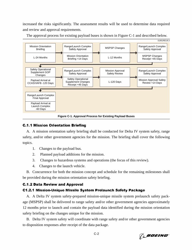
C-2
increased the risks significantly. The assessment results will be used to determine data required
and review and approval requirements.
The approval process for existing payload buses is shown in Figure C-1 and described below.
C.1.1 Mission Orientation Briefing
A. A mission orientation safety briefing shall be conducted for Delta IV system safety, range
safety, and/or other government agencies for the mission. The briefing shall cover the following
topics.
1. Changes to the payload bus.
2. Planned payload additions for the mission.
3. Changes to hazardous systems and operations (the focus of this review).
4. Changes to the launch vehicle.
B. Concurrence for both the mission concept and schedule for the remaining milestones shall
be provided during the mission orientation safety briefing.
C.1.2 Data Review and Approval
C1.2.1 Mission-Unique Missile System Prelaunch Safety Package
A. A Delta IV system safety-prepared mission-unique missile system prelaunch safety pack-
age (MSPSP) shall be delivered to range safety and/or other government agencies approximately
12 months prior to launch and contain the payload data identified during the mission orientation
safety briefing on the changes unique for the mission.
B. Delta IV system safety will coordinate with range safety and/or other government agencies
to disposition responses after receipt of the data package.
01951REU9.3
Mission OrientationBriefing
Range/Launch ComplexSafety Approval
Mission OrientationBriefing +14 Days
MSPSP Changes
L-12 MonthsL-24 Months
Safety OperationalSupplement GOP
Changes
Payload Arrival atCCAS/VAFB -120 Days
Range/Launch ComplexSafety Approval
Safety OperationalSupplement Changes
Receipt +45 Days
Mission ApprovalSafety Review
L-120 Days
Range/Launch ComplexSafety Approval
Mission Approval SafetyReview +14 Days
Range/Launch ComplexFinal Approval
Payload Arrival atLaunch Complex
-60 Days
Range/Launch ComplexSafety Approval
MSPSP ChangesReceipt +45 Days
Figure C-1. Approval Process for Existing Payload Buses
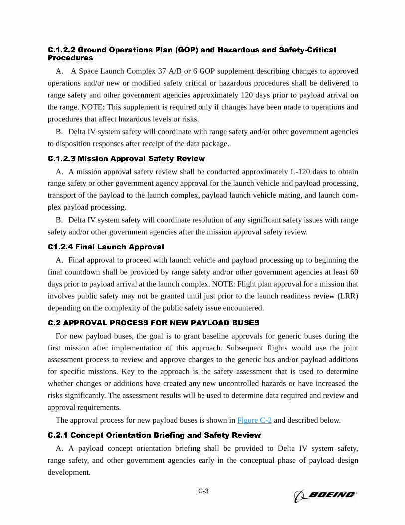
C-3
C.1.2.2 Ground Operations Plan (GOP) and Hazardous and Safety-Critical Procedures
A. A Space Launch Complex 37 A/B or 6 GOP supplement describing changes to approved
operations and/or new or modified safety critical or hazardous procedures shall be delivered to
range safety and other government agencies approximately 120 days prior to payload arrival on
the range. NOTE: This supplement is required only if changes have been made to operations and
procedures that affect hazardous levels or risks.
B. Delta IV system safety will coordinate with range safety and/or other government agencies
to disposition responses after receipt of the data package.
C.1.2.3 Mission Approval Safety Review
A. A mission approval safety review shall be conducted approximately L-120 days to obtain
range safety or other government agency approval for the launch vehicle and payload processing,
transport of the payload to the launch complex, payload launch vehicle mating, and launch com-
plex payload processing.
B. Delta IV system safety will coordinate resolution of any significant safety issues with range
safety and/or other government agencies after the mission approval safety review.
C1.2.4 Final Launch Approval
A. Final approval to proceed with launch vehicle and payload processing up to beginning the
final countdown shall be provided by range safety and/or other government agencies at least 60
days prior to payload arrival at the launch complex. NOTE: Flight plan approval for a mission that
involves public safety may not be granted until just prior to the launch readiness review (LRR)
depending on the complexity of the public safety issue encountered.
C.2 APPROVAL PROCESS FOR NEW PAYLOAD BUSES
For new payload buses, the goal is to grant baseline approvals for generic buses during the
first mission after implementation of this approach. Subsequent flights would use the joint
assessment process to review and approve changes to the generic bus and/or payload additions
for specific missions. Key to the approach is the safety assessment that is used to determine
whether changes or additions have created any new uncontrolled hazards or have increased the
risks significantly. The assessment results will be used to determine data required and review and
approval requirements.
The approval process for new payload buses is shown inFigure C-2and described below.
C.2.1 Concept Orientation Briefing and Safety Review
A. A payload concept orientation briefing shall be provided to Delta IV system safety,
range safety, and other government agencies early in the conceptual phase of payload design
development.
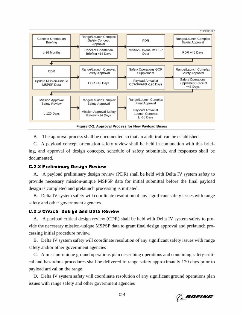
C-4
B. The approval process shall be documented so that an audit trail can be established.
C. A payload concept orientation safety review shall be held in conjunction with this brief-
ing, and approval of design concepts, schedule of safety submittals, and responses shall be
documented.
C.2.2 Preliminary Design Review
A. A payload preliminary design review (PDR) shall be held with Delta IV system safety to
provide necessary mission-unique MSPSP data for initial submittal before the final payload
design is completed and prelaunch processing is initiated.
B. Delta IV system safety will coordinate resolution of any significant safety issues with range
safety and other government agencies.
C.2.3 Critical Design and Data Review
A. A payload critical design review (CDR) shall be held with Delta IV system safety to pro-
vide the necessary mission-unique MSPSP data to grant final design approval and prelaunch pro-
cessing initial procedure review.
B. Delta IV system safety will coordinate resolution of any significant safety issues with range
safety and/or other government agencies
C. A mission-unique ground operations plan describing operations and containing safety-criti-
cal and hazardous procedures shall be delivered to range safety approximately 120 days prior to
payload arrival on the range.
D. Delta IV system safety will coordinate resolution of any significant ground operations plan
issues with range safety and other government agencies
01952REU9.2
Concept OrientationBriefing
Range/Launch ComplexSafety Concept
Approval
Concept OrientationBriefing +14 Days
PDR
Mission-Unique MSPSPData
Range/Launch ComplexSafety Approval
PDR +45 DaysL-36 Months
CDR
Update Mission-UniqueMSPSP Data
Range/Launch ComplexSafety Approval
CDR +45 Days
Safety Operations GOPSupplement
Payload Arrival atCCAS/VAFB -120 Days
Range/Launch ComplexSafety Approval
Safety OperationsSupplement Receipt
+45 Days
Mission ApprovalSafety Review
L-120 Days
Range/Launch ComplexSafety Approval
Mission Approval SafetyReview +14 Days
Range/Launch ComplexFinal Approval
Payload Arrival atLaunch Complex
L -60 Days
Figure C-2. Approval Process for New Payload Buses
C-5
C.2.4 Mission Approval Safety Review
A. A mission approval safety review shall be conducted by Delta IV system safety
approximately L-120 days to obtain range safety approval for launch vehicle and payload pro-
cessing, transport to the payload launch pad, payload launch vehicle mating, and launch pad
payload processing.
B. Delta IV system safety will coordinate resolution of any significant safety issues with range
safety and other government agencies
C.2.5 Final Launch Approval
Final approval to proceed with launch vehicle and payload processing up to beginning the final
countdown shall be provided by range safety and/or other government agencies at least 60 days
prior to payload arrival at the launch complex. NOTE: Flight plan approval for a mission that
involves public safety may not be granted until just prior to the LRR, depending on the complex-
ity of the public safety issue encountered. Typically, easterly launch azimuths can be approved at
least 120 days prior to launch. Alternatively, high-inclination launches may require additional risk
analyses that can lengthen the final flight plan approval process.
C.3 INCIDENTAL RANGE SAFETY ISSUES
Incidental range safety/launch complex issues such as component failures, test failures, and the
discovery of unforeseen hazards occurring after baseline approvals shall be worked in real time as
part of the final approval process for an individual launch. Typically, these issues involve the
launch vehicle and not the payload.
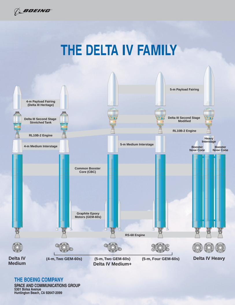
Delta III Second Stage Stretched Tank
4-m Payload Fairing(Delta III Heritage)
4-m Medium Interstage
5-m Payload Fairing
Delta III Second Stage Modified
Common BoosterCore (CBC)
RS-68 Engine
Graphite Epoxy Motors (GEM-60s)
RL10B-2 Engine
Booster Nose Cone
Booster Nose Cone
Heavy Interstage
RL10B-2 Engine
5-m Medium Interstage
(5-m, Two GEM-60s)Delta IV Medium+
(4-m, Two GEM-60s) (5-m, Four GEM-60s)Delta IVMedium
Delta IV Heavy