
Datasheet MEC Floorscanner v03 2014
3
MEC-Floorscanner High Performance Tank Floorscanners Innospection Limited Unit 1, Howemoss Avenue, Kirkhill Industrial Estate, Dyce, AB21 0GP, Aberdeen, United Kingdom Tel : +44 (0)1224-724744 Email : info@innospe ction.com Web : www.innospe ction-technologies.co m Web : www.innospe ction.com © Copyright Innospection Ltd 2014. All rights reserved. Datasheet MEC-Floorscanner v03-2014 Key Features & Benefits High defect detection sensitivity for corrosion and pitting in tanks - with wall thickness to 30mm - with coating thickness to 10mm High inspection speed of approx. 25m/min Average accuracy of +/- 10% Detection capability for internal and external defects from < 10% wall loss, depending on wall thickness and defect size from Ø 3mm Detection and distinction between topside and underside defects as well as false calls by means of the signal phase Ability to inspect stainless and carbon steel tanks Designed to cover maximum inspectable areas of floor plates and overlap welds, including close to the tank shell Minimal surface preparation prior to inspection Allow tolerances in material magnetic properties MEC-Floorscanner The MEC-Floorscanners are designed and built for high speed, high performance inspection of storage tank floors. Based on the Saturation Low Frequency Eddy Current technique, the MEC-Floorscanners enable the detection of topside and underside corrosion in coated and uncoated tank floors of both ferrous and non-ferrous materials. Saturation Low Frequency Eddy Current is a dynamic electromagnetic technique that utilises Eddy Current in combination w ith a Direct Current magn etic field. By superimposing the DC ma gnetisation onto the Eddy Current field lines, the depth of penetration is increased such that underside corrosion attack (metal loss) can be detected from the topside. This includes very small diameter and volume isolated internal pits with wall loss from 10% onwards. The MEC-Floorscanners have powerful scanning capabilities in excess of 3 times the material thickness and 5 times the coating thickness. They are capable of detecting defects less than half the size of what could be detected by the MFL technique. With its comprehensive reporting software, accurate, reliable and repeatable inspection results are provided in real time. The advanced colour condition mapping report provides an analysis of both the detected external and internal defects in terms of size, wall loss severity and location.
Transcript of Datasheet MEC Floorscanner v03 2014
8/10/2019 Datasheet MEC Floorscanner v03 2014
http://slidepdf.com/reader/full/datasheet-mec-floorscanner-v03-2014 1/2
MEC-FloorscannerHigh Performance Tank Floorscanners
Innospection LimitedUnit 1, Howemoss Avenue, Kirkhill Industrial Estate, Dyce, AB21 0GP, Aberdeen, United Kingdom
Tel : +44 (0)1224-724744 Email : [email protected] : www.innospection-technologies.com Web : www.innospection.com
© Copyright Innospection Ltd 2014. All rights reserved.
Datasheet MEC-Floorscanner v03-2014
Key Features & Benefits
High defect detection sensitivity for corrosion and
pitting in tanks
- with wall thickness to 30mm
- with coating thickness to 10mm
High inspection speed of approx. 25m/min
Average accuracy of +/- 10%
Detection capability for internal and external defects
from < 10% wall loss, depending on wall thickness anddefect size from Ø 3mm
Detection and distinction between topside and
underside defects as well as false calls by means of the
signal phase
Ability to inspect stainless and carbon steel tanks
Designed to cover maximum inspectable areas of floor
plates and overlap welds, including close to the tank
shell
Minimal surface preparation prior to inspection
Allow tolerances in material magnetic properties
MEC-Floorscanner
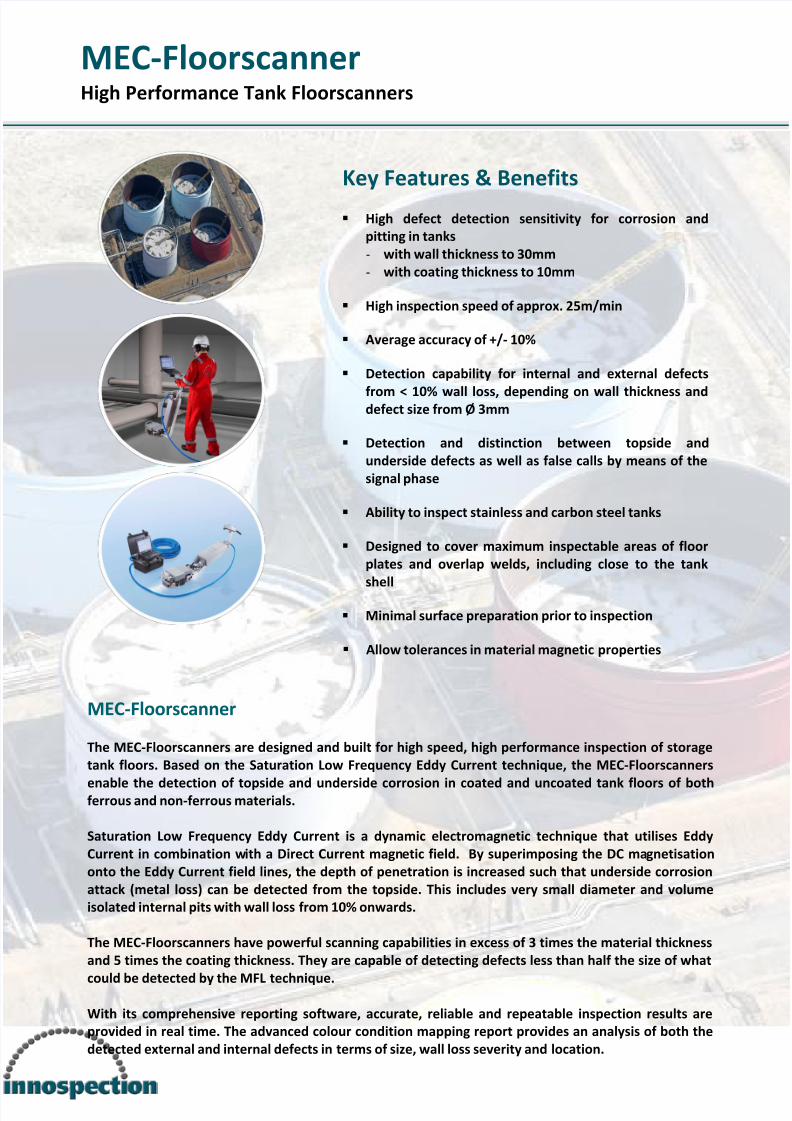
The MEC-Floorscanners are designed and built for high speed, high performance inspection of storage
tank floors. Based on the Saturation Low Frequency Eddy Current technique, the MEC-Floorscanners
enable the detection of topside and underside corrosion in coated and uncoated tank floors of bothferrous and non-ferrous materials.
Saturation Low Frequency Eddy Current is a dynamic electromagnetic technique that utilises Eddy
Current in combination with a Direct Current magnetic field. By superimposing the DC magnetisation
onto the Eddy Current field lines, the depth of penetration is increased such that underside corrosion
attack (metal loss) can be detected from the topside. This includes very small diameter and volume
isolated internal pits with wall loss from 10% onwards.
The MEC-Floorscanners have powerful scanning capabilities in excess of 3 times the material thickness
and 5 times the coating thickness. They are capable of detecting defects less than half the size of what
could be detected by the MFL technique.
With its comprehensive reporting software, accurate, reliable and repeatable inspection results are
provided in real time. The advanced colour condition mapping report provides an analysis of both the
detected external and internal defects in terms of size, wall loss severity and location.
8/10/2019 Datasheet MEC Floorscanner v03 2014
http://slidepdf.com/reader/full/datasheet-mec-floorscanner-v03-2014 2/2
MEC-FloorscannerHigh Performance Tank Floorscanners
Innospection LimitedUnit 1, Howemoss Avenue, Kirkhill Industrial Estate, Dyce, AB21 0GP, Aberdeen, United Kingdom
Tel : +44 (0)1224-724744 Email : [email protected] : www.innospection-technologies.com Web : www.innospection.com
© Copyright Innospection Ltd 2014. All rights reserved.
Datasheet MEC-Floorscanner v03-2014
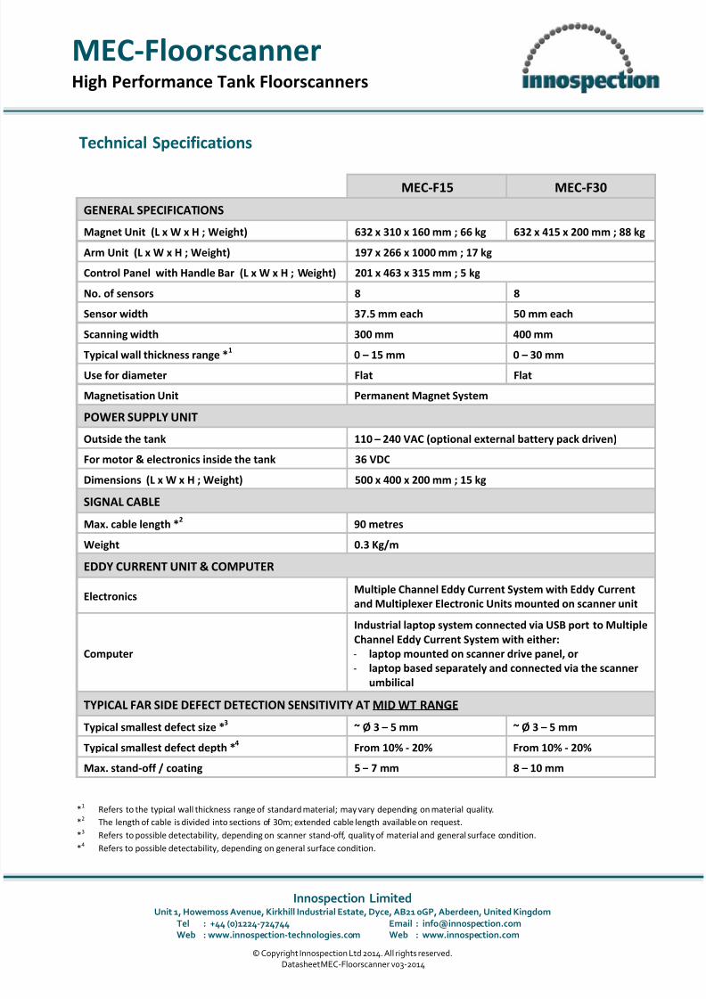
Technical Specifications
MEC-F15 MEC-F30
GENERAL SPECIFICATIONS
Magnet Unit (L x W x H ; Weight) 632 x 310 x 160 mm ; 66 kg 632 x 415 x 200 mm ; 88 kg
Arm Unit (L x W x H ; Weight) 197 x 266 x 1000 mm ; 17 kg
Control Panel with Handle Bar (L x W x H ; Weight) 201 x 463 x 315 mm ; 5 kg
No. of sensors 8 8
Sensor width 37.5 mm each 50 mm each
Scanning width 300 mm 400 mm
Typical wall thickness range *1 0 –
15 mm 0 –
30 mm
Use for diameter Flat Flat
Magnetisation Unit Permanent Magnet System
POWER SUPPLY UNIT
Outside the tank 110 – 240 VAC (optional external battery pack driven)
For motor & electronics inside the tank 36 VDC
Dimensions (L x W x H ; Weight) 500 x 400 x 200 mm ; 15 kg
SIGNAL CABLE
Max. cable length *2
90 metres
Weight 0.3 Kg/m
EDDY CURRENT UNIT & COMPUTER
ElectronicsMultiple Channel Eddy Current System with Eddy Current
and Multiplexer Electronic Units mounted on scanner unit
Computer
Industrial laptop system connected via USB port to Multiple
Channel Eddy Current System with either:
- laptop mounted on scanner drive panel, or
- laptop based separately and connected via the scanner
umbilical
TYPICAL FAR SIDE DEFECT DETECTION SENSITIVITY AT MID WT RANGE
Typical smallest defect size *3 ~ Ø 3 – 5 mm ~ Ø 3 – 5 mm
Typical smallest defect depth *4 From 10% - 20% From 10% - 20%
Max. stand-off / coating 5 – 7 mm 8 – 10 mm
*1 Refers to the typical wall thickness range of standard material; may vary depending on material quality.
*2 The length of cable is divided into sections of 30m; extended cable length available on request.
*3 Refers to possible detectability, depending on scanner stand-off, quality of material and general surface condition.
*4 Refers to possible detectability, depending on general surface condition.


![[GF] Toradora! v03](https://static.fdocument.pub/doc/165x107/577c86011a28abe054bf675e/gf-toradora-v03.jpg)