CUSTOMER : MOTOROLA CUSTOMER P/N : 524475-034 PROJECT NAME : DCX700 ... Sheets/Lite-On...
37
CUSTOMER : MOTOROLA CUSTOMER P/N : 524475-034 PROJECT NAME : DCX700 LITE-ON P/N : PB-1200-1M01 光 寶 科 技 股 份 有 限 公 司 LITE-ON TECHNOLOGY CORPORATION 1
Transcript of CUSTOMER : MOTOROLA CUSTOMER P/N : 524475-034 PROJECT NAME : DCX700 ... Sheets/Lite-On...

CUSTOMER : MOTOROLA
CUSTOMER P/N : 524475-034
PROJECT NAME : DCX700
LITE-ON P/N : PB-1200-1M01
光 寶 科 技 股 份 有 限 公 司
LITE-ON TECHNOLOGY CORPORATION
1

20W Power Supply History Card
PB-1200-1M01 DCX700
History Card
Project Name : 524475-034
Liteon Model Name : PB-1200-1M01 Rev. 01
Description : Switching Power Supply
Customer : Motorola/GIT
Issue Date : 12/22/2009
Elec. Design Engineer : Arvin Wang
Elec. Design Leader : Gary Shyi
Mech. Design Engineer : Elaine Chen
3

General Instrument of Taiwan, Ltd. Sheet 1 of 28 No. 1, Lane 232, Pao Chiao Road, Hsin Tien, Taipei, Taiwan, R.O.C. T: +886-2-2-918-9145
Internal Level 2
asizemot.dot | 473452-001 Rev W
General Instrument of Taiwan, Ltd. 8
This document is the property of Motorola, Inc., Home & Networks Mobility. This document may only be distributed to: (i) a Motorola employee ("Motorolan") having a legitimate business need for the information contained herein, or (ii) a non-Motorolan having a legitimate business need for the information contained herein. No license, expressed or implied, under any patent, copyright or trade secret right is granted or implied by the conveyance of this document. No part of this document may be reproduced, transmitted, transcribed, stored in a retrieval system, translated into any language or computer language, in any form or by any means, electronic, mechanical, magnetic, optical, chemical, manual, or otherwise without the prior written permission of Motorola, Inc. Home & Networks Mobility. (See Document Security Standard, 320190-000 for details.)
MOTOROLA, the Stylized M Logo and all other trademarks indicated as such herein are trademarks of Motorola, Inc. ® Reg. U.S. Pat. & Tm. Off. All other product or service names are the property of their respective owners.
Copyright © 2000-2010 Motorola, Inc. All rights reserved.
Document Title P/S,SWG,90-140VOLTS,57-63HZFREQ,20W,5V/4A, DCX700, LEAD-FREE / ROHS COMPLIANT
Number 524475-034 Revision B Revision Date 4/14/2010
Author(s) Bryan Zublin / Kevin Huang

P/S,SWG,90-140VOLTS,57-63HZFREQ,20W,5V/4A, DCX700, LEAD-FREE / ROHS COMPLIANT
Motorola 524475-034 Sheet 2 of 28 Printed Copies of this Document are Not Controlled Revision B
Revision History – see Workflow History for approvers and approval dates, and Notice for release dates Rev Notice # Description Author Revision
Date
A C389038 Release specification. Bryan Zublin / Kevin Huang
01/20/2010
B C403877 Update Table 1- Electrical Requirements - adding condition on “Minimum, No load”
3.7 No Load Condition – adding text “The adapter ( PSU ) needs to keep in specified regulation range during system at stand by mode 0mA under full line / frequency condition ”
Bryan Zublin / Kevin Huang
04/14/2010

P/S,SWG,90-140VOLTS,57-63HZFREQ,20W,5V/4A, DCX700, LEAD-FREE / ROHS COMPLIANT
Motorola 524475-034 Sheet 3 of 28 Printed Copies of this Document are Not Controlled Revision B
TABLE OF CONTENTS
1. Scope ..................................................................................................................................................................6 2. Applicable Documents........................................................................................................................................6 3. Requirements ......................................................................................................................................................6
3.1. General................................................................................................................................................................6 3.2. RoHS Requirements ...........................................................................................................................................6
3.2.1. Marking ..............................................................................................................................................................6 3.2.2. Motorola Controlled & Reportable Materials Disclosure ...................................................................................6 3.2.3. Orderable Part Number.......................................................................................................................................6 3.2.4. Solderability........................................................................................................................................................6 3.2.5 Moisture/Reflow Sensitivity Classification for Nonhermetic Solid State...........................................................6 Surface Mount Devices ....................................................................................................................................................6 3.2.6 Lead Finish .........................................................................................................................................................6
3.3. Input Line Voltage ..............................................................................................................................................7 3.4. Input Line Frequency..........................................................................................................................................7 3.5. Over Current Input Protection ............................................................................................................................7 3.6. Operating Efficiency & No Load Input Power ...................................................................................................7 3.7. No Load Condition .............................................................................................................................................7 3.8. Holdup Time.......................................................................................................................................................8 3.9. CA Proposition 65 & Motorola Controlled & Reportable Materials Disclosure ................................................9 3.10. Over-current Protection ....................................................................................................................................11 3.11. Maximum Load ................................................................................................................................................11 3.12. DC Output Surge Current .................................................................................................................................11 3.13. Brownout ..........................................................................................................................................................11 3.14. Transient Load Response..................................................................................................................................11 3.15. Overshoot..........................................................................................................................................................11 3.16. Power-up Rise Time .........................................................................................................................................11
4. Mechanical Requirements.................................................................................................................................12 4.1. Input Cord and Connector.................................................................................................................................12 4.2. Output Cord and Connector ..............................................................................................................................12 4.3. Mating Connector .............................................................................................................................................12 4.4. Physical Size.....................................................................................................................................................13
4.4.1. Configuration A................................................................................................................................................13 4.4.2. Configuration B ................................................................................................................................................13 4.4.3. Configuration C ................................................................................................................................................13
4.5. Case material ....................................................................................................................................................14

P/S,SWG,90-140VOLTS,57-63HZFREQ,20W,5V/4A, DCX700, LEAD-FREE / ROHS COMPLIANT
Motorola 524475-034 Sheet 4 of 28 Printed Copies of this Document are Not Controlled Revision B
4.6. Weight (Maximum) ..........................................................................................................................................14 4.7. PCB Material ....................................................................................................................................................14 4.8. Cooling Method ................................................................................................................................................14 4.9. Strain Relief ......................................................................................................................................................14
5. Environmental Requirements ...........................................................................................................................15 5.1. General..............................................................................................................................................................15 5.2. Humidity...........................................................................................................................................................15
5.2.1. Operating Relative Humidity............................................................................................................................15 5.2.2. Storage Humidity..............................................................................................................................................15 5.2.3. Humidity shock (non-condensing)....................................................................................................................15
5.3. Electrostatic Discharge .....................................................................................................................................16 6. Agency Approval Requirements.......................................................................................................................17
6.1. Conducted and Radiated Emissions..................................................................................................................17 6.2. Safety ................................................................................................................................................................17
6.2.1. Electric Strength Requirements ........................................................................................................................18 6.3. Leakage current ................................................................................................................................................18 6.4. Surge Immunity ................................................................................................................................................19
6.4.1. Surge Test - UL60065 ......................................................................................................................................19 6.4.2. Surge Immunity - IEEE Standard C62.41.2-2002 ............................................................................................20
6.5. Approval Markings ...........................................................................................................................................21 7. Quality Assurance Provisions ...........................................................................................................................22
7.1. Responsibility for Inspection ............................................................................................................................22 7.2. Quality System..................................................................................................................................................22 7.3. Acceptance Tests ..............................................................................................................................................22 7.4. Right to Inspect.................................................................................................................................................22 7.5. Test Equipment and Inspection Failures...........................................................................................................22 7.6. Inspection Records............................................................................................................................................22 7.7. General..............................................................................................................................................................22 7.8. Preparation for Delivery ...................................................................................................................................22 7.9. Process Requirements .......................................................................................................................................23 7.10. Component Change ..........................................................................................................................................23 7.11. MTBF ...............................................................................................................................................................23 7.12. Lifetime of Aluminum Electrolytic Capacitors ................................................................................................23 7.13. On-going Reliability Test (ORT) Requirements...............................................................................................23 7.14. Demonstrated Life Test (DLT) Requirements ..................................................................................................23 7.15. Out-of-box Audit Requirements .......................................................................................................................23 7.16. Burn-in Requirements.......................................................................................................................................23 7.17. Monthly Report Requirements..........................................................................................................................24
P/S,SWG,90-140VOLTS,57-63HZFREQ,20W,5V/4A, DCX700, LEAD-FREE / ROHS COMPLIANT
Motorola 524475-034 Sheet 5 of 28 Printed Copies of this Document are Not Controlled Revision B
7.18. Component De-Rating ......................................................................................................................................24 8. Documentation..................................................................................................................................................24 9. Version history..................................................................................................................................................24 10. Appendix A.......................................................................................................................................................25
10.1. Component De-rating .......................................................................................................................................25
P/S,SWG,90-140VOLTS,57-63HZFREQ,20W,5V/4A, DCX700, LEAD-FREE / ROHS COMPLIANT
Motorola 524475-034 Sheet 6 of 28 Printed Copies of this Document are Not Controlled Revision B
1. SCOPE This document describes the requirements of a low cost external switching power supply to power the DCX700 digital cable TV set-top box. The intended market is North America (US, Canada and Mexico).
2. APPLICABLE DOCUMENTS UL60950-1 Information Technology Equipment – Safety – Part 1: General Requirements
UL60065 7th edition Audio, Video and Similar Electronic Apparatus – Safety Requirements
FCC Code of Federal Regulations, Telecommunications Section, CFR-47 Part 15 Class B, October 1999
CSA C22.2 No. 60065 Audio, Video and Similar Electronic Apparatus – Safety requirements
ENERGY STAR Program Requirements for Single Voltage External Ac-Dc and Ac-Ac Power Supplies Eligibility Criteria
3. REQUIREMENTS
3.1. General The power supply shall meet the electrical requirements specified in Table 1 under the operating environmental requirements specified in Table 2. It needs to be meet RoHS compliance. It is a RoHS adaptor.
3.2. RoHS Requirements 3.2.1. Marking As space permits, part shall be marked with the manufacturer's name or trademark, manufacturer's part number, and lot code or date code.
3.2.2. Motorola Controlled & Reportable Materials Disclosure Components supplied to this specification must be compliant to Appendix C, Section 2, Global Compliance Acceptance Criteria of the Motorola "W-18" specification.
Supplier must complete a Compliance Connect material declaration (".cxs" spreadsheet) for the component supplied.
3.2.3. Orderable Part Number Components must have a manufacturer part number that distinguishes them from similar parts that do not meet the "Global" compliance standard (e.g. legacy parts that are Pb-bearing and/or non-ROHS compliant). This requirement does not apply to components that have been Globally Compliant since 1/1/2002 or have been since their introduction to the marketplace.
3.2.4. Solderability Components must meet J-STD-002 latest revision. Manufacturers must qualify their parts to assure that solderability is maintained after storage in typical uncontrolled warehouse conditions.
3.2.5 Moisture/Reflow Sensitivity Classification for Nonhermetic Solid State Surface Mount Devices
Surface mount devices supplied must be Moisture Sensitivity Level 1, 2, 2a, or 3 per J-STD-020C (or later) at the peak temperatures and profiles specified in Table 4-2 of that standard.
3.2.6 Lead Finish Acceptable lead finishes per JEDEC JESD97 are:

P/S,SWG,90-140VOLTS,57-63HZFREQ,20W,5V/4A, DCX700, LEAD-FREE / ROHS COMPLIANT
Motorola 524475-034 Sheet 7 of 28 Printed Copies of this Document are Not Controlled Revision B
e1 SnAgCu Acceptable, but not preferred as it is not a backward compatible finish for (lower temperature) lead solder reflow processes. Note, however, that SnAgCu is the preferred finish for all lead-free BGA packages
e2 Sn Alloys (no Bi, Zn, or SnAgCu) Acceptable. SnCu not preferred.
e3 Sn Acceptable. Matte tin strongly preferred.
e4 Precious metal (e.g.Ag,Au,NiPd,NiPdAu) Acceptable.
e6 Contains Bi Acceptable where Bi is < 4%.
Notes:
1. e2, e3, e6 (Pure tin or high content tin alloy finishes) require compliance to NEMI "Tin Whisker Acceptance Test Requirements" (7/28/2004 revision or later) for a "Class II" product application.
2. Where an underplate is used, Nickel (Ni) is preferred.
3.3. Input Line Voltage Input line voltage defines the AC power mains voltage range over which the supply shall operate and maintain all specified parameters. Refer to Table 1 for requirements.
3.4. Input Line Frequency Input line frequency is the frequency of the AC power mains measured at the mains outlet at the subscriber’s residence. The supply shall operate within all specified parameters over the entire range from minimum to maximum input line frequency. Refer to Table 1 for requirements.
3.5. Over Current Input Protection To meet agency safety requirements, the power supply shall be designed with over-current, thermal, or energy limiting circuitry. There shall be an over current protection device in the AC line path. The over current protection device must be able to survive all abnormal conditions (lightning, start-up, AC surge, and output short circuit) without failing.
3.6. Operating Efficiency & No Load Input Power The operating efficiency is defined to be the percent ratio of the output power to the input power.
The efficiency shall meet the California Energy Commission Appliance Efficiency Regulations, Standards for Power Supplies and the requirements specified in document ENERGY STAR Program Requirements for Single Voltage External Ac-Dc and Ac-Ac Power Supplies Eligibility Criteria. The average efficiency for this 20 watt power supply shall be 78.6% minimum at 115 VAC 60 Hz input, tested with output DC current loads of 1000 mA, 2000 mA, 3000 mA, and 4000 mA. The test shall be performed at 23 +/-5 deg C ambient temperature following preconditioning at 100% of rated output current for 30 minutes.
3.7. No Load Condition No load condition refers to an operating condition of the supply when there is no output load. Under no load conditions the supply shall operate in a stable and non-destructive manner while not meeting some or all of the stated specifications.
The input power under the no load condition shall not exceed 0.3 watts.
"The adapter ( PSU ) needs to keep in specified regulation range during system at stand by mode 0 mA under full line / frequency condition".

P/S,SWG,90-140VOLTS,57-63HZFREQ,20W,5V/4A, DCX700, LEAD-FREE / ROHS COMPLIANT
Motorola 524475-034 Sheet 8 of 28 Printed Copies of this Document are Not Controlled Revision B
3.8. Holdup Time Holdup time refers to the time it takes for a loss of input voltage to propagate through the power supply and affect the output voltages. Holdup time spec must be met over the entire operational line voltage range. Holdup time shall be measured by monitoring the output voltages and measuring the time it takes for the first affected output voltage to pass through the lower bound of the regulation threshold after input power to the converter is removed. The initial conditions of loading and input voltage are maximum load and minimum operational line input. The holdup time is measured by triggering an oscilloscope on the loss of input voltage while monitoring the conditions of the output voltages. At least one set of measurements should be made at the zero crossing time of the input AC power signal. The holdup time shall be 10 msec minimum for a complete AC line dropout at operational input voltage (115 VAC, 60 Hz) and maximum output load (4000 mA).

P/S,SWG,90-140VOLTS,57-63HZFREQ,20W,5V/4A, DCX700, LEAD-FREE / ROHS COMPLIANT
Motorola 524475-034 Sheet 9 of 28 Printed Copies of this Document are Not Controlled Revision B
3.9. CA Proposition 65 & Motorola Controlled & Reportable Materials Disclosure Items supplied to this specification must comply with California Proposition 65. This specifically limits lead content to less than 300 ppm. Motorola has additional requirements regarding the maximum levels of substances (other than lead) that may be contained in products you supply. The substances and maximum levels are specified in the Motorola “Controlled and Reportable Materials Disclosure” document (12G02897W18). It is your responsibility to understand these requirements through the vendor qualification process and to provide certification of compliance with these requirements as may be requested by Motorola from time to time.
Table 1 - Electrical Requirements
Parameter Value Units
Minimum 90
Nominal 115
Operational Input Line Voltage
Maximum 140
VAC (rms)
Minimum 57
Nominal 60
Input Line Frequency
Maximum 63
Hz
Minimum, loaded +4.8
Nominal +5.1
Maximum, load = 100 mA to 1299 mA
+5.45
Maximum, load = 1300 mA to 4000 mA
+5.25
Maximum, no load +5.45
Output Voltage (note 1)
Minimum, no load +4.75
Volts DC
Negative Output Voltage Transients
Absolute Minimum -0.5 Volts DC
Minimum 100 Output Load Current (note 1)
Maximum 4000
mA (rms)
Output Voltage Ripple, measured with 1 MHz first order lowpass filter
Maximum 50 mVp-p
Notes: 1. The output load current shall be applied to the mated connector end so that the contact resistance of both connectors is included in the measurement, as shown in Figure 1. The output voltage measurement shall be performed with the two connectors mated and the measurement point shall be the exposed pins of the mated connector, as shown in Figure 1. See section 4.3 for the mating connector part number.

P/S,SWG,90-140VOLTS,57-63HZFREQ,20W,5V/4A, DCX700, LEAD-FREE / ROHS COMPLIANT
Motorola 524475-034 Sheet 10 of 28 Printed Copies of this Document are Not Controlled Revision B
Figure 1 Output Load Current and Output Voltage Measurement Points

P/S,SWG,90-140VOLTS,57-63HZFREQ,20W,5V/4A, DCX700, LEAD-FREE / ROHS COMPLIANT
Motorola 524475-034 Sheet 11 of 28 Printed Copies of this Document are Not Controlled Revision B
3.10. Over-current Protection The power supply shall not be damaged when the output is subjected to DC loads exceeding the maximum listed in Table 1. The power supply shall not be damaged when the output is subjected to a short circuit condition. The unit shall recover and function automatically after the over-current or short condition is removed.
3.11. Maximum Load The power supply shall power-up normally and not sustain any damage when the applied load is an active load with constant power load of 20 watts when the output voltage is above 3.5V. The requirement shall be met for any AC input voltage between 0 VAC and the maximum input voltage specified in Table 1. The 20 watt active load will result in increasing load current as the output voltage drops (4 amps at 5V; 5 amps at 4V; 5.7 amps at 3.5V, etc).
3.12. DC Output Surge Current The power supply shall be able to power-up and operate normally following AC power application when loaded with the following: 1.25 ohm resistor in parallel with 2500 uF capacitor. The capacitor shall be discharged prior to the application of the AC input voltage.
3.13. Brownout Any fluctuations in AC line voltage (such as slowly decreasing line voltage down to zero volts or slowly increasing line voltage up to maximum input voltage from zero volts) shall not cause damage to the power supply.
3.14. Transient Load Response The power supply dynamic load regulation shall be within the limits specified in Table 1 as measured at 50%-75%-50% load change at any frequency up to 250 Hz with 50% duty.
3.15. Overshoot During turn-on or turn-off, the output voltage shall not exceed +5.8V under all load conditions.
3.16. Power-up Rise Time Following the application of AC input voltage, the DC output voltage rise time from 10% to 90% of steady state value shall be 20 msec maximum. There shall be a smooth and continuous ramp of DC voltage from 10% to 90% of its steady state value. The requirement shall be met under all load conditions listed in Table 1, section 3.11 and section 3.12.

P/S,SWG,90-140VOLTS,57-63HZFREQ,20W,5V/4A, DCX700, LEAD-FREE / ROHS COMPLIANT
Motorola 524475-034 Sheet 12 of 28 Printed Copies of this Document are Not Controlled Revision B
4. MECHANICAL REQUIREMENTS 4.1. Input Cord and Connector
The input line cord shall be 3 to 3.3 feet long and must comply with safety standards for a North American line cord. The input cable connection shall be referred to as a North American 2 blade plug, polarized, with no ground. Rating, finish, and design shall meet all of the required safety requirements for the said market. The plug that will be used is a NEMA 1-15 P. The input cable shall be fixed to the adaptor.
4.2. Output Cord and Connector The output cord length shall be 6 to 6.6 feet long. The output cord shall be 2-conductor stranded wire.
The output connector shall be a molded miniature female barrel power plug. The outside diameter shall be 4 mm nominal and the inside diameter shall be 1.7 mm nominal. The dimensions shall meet the general requirements of EIAJ RC-5320A for connector type EIAJ-02.
The output connector center contact shall be positive polarity and the outer sleeve shall be the negative polarity.
The output cord shall have affixed to it a low cost paper label with the text "FOR USE WITH MOTOROLA DCX PRODUCTS". The label shall be located within one inch of the output connector body.
4.3. Mating Connector The mating DC connector shall be used for all electrical tests so that the total contact resistance of the mated pair is included. Refer to Figure 1. Acceptable part numbers for the mating connector are: Winpoint DCJ-17R-K3-H (Motorola 503402-006)..

P/S,SWG,90-140VOLTS,57-63HZFREQ,20W,5V/4A, DCX700, LEAD-FREE / ROHS COMPLIANT
Motorola 524475-034 Sheet 13 of 28 Printed Copies of this Document are Not Controlled Revision B
4.4. Physical Size 4.4.1. Configuration A An acceptable outline dimensions and label is shown in attached files – vendor A.
D:\Data\DCX700\Adapter\SPEC\Rev_A
4.4.2. Configuration B An acceptable outline dimensions and label is shown in attached files – vendor B.
D:\Data\DCX700\Adapter\SPEC\Rev_A
4.4.3. Configuration C An acceptable outline dimensions and label is shown in attached files – vendor C.
TBD

P/S,SWG,90-140VOLTS,57-63HZFREQ,20W,5V/4A, DCX700, LEAD-FREE / ROHS COMPLIANT
Motorola 524475-034 Sheet 14 of 28 Printed Copies of this Document are Not Controlled Revision B
4.5. Case material The case material must meet UL requirements.
4.6. Weight (Maximum) 300g
4.7. PCB Material The PCB material used shall be flame rated as type 94V-0. FR-4, Cem-1 or equivalent board material is acceptable.
The PCB material must meet UL requirements.
4.8. Cooling Method The power supply shall meet UL requirements for external case temperature.
4.9. Strain Relief The input and output cords shall withstand a minimum pull out force of 2 pounds.
The pull force can be applied at any angle.
There should be no visible or electrical damage found.

P/S,SWG,90-140VOLTS,57-63HZFREQ,20W,5V/4A, DCX700, LEAD-FREE / ROHS COMPLIANT
Motorola 524475-034 Sheet 15 of 28 Printed Copies of this Document are Not Controlled Revision B
5. ENVIRONMENTAL REQUIREMENTS 5.1. General
The power supply shall meet the environmental requirements specified in Table 2.
Table 2 - Environmental Requirements
Operating Temperature 0 to 40 deg C
Storage Temperature -30 to 80 deg C
Humidity (Operating) See section 5.2
Humidity (Non-operating) See section 5.2
Vibration (Non-operating) 6 G's rms random vibration on X, Y, and Z axis, 20 Hz to 500 Hz, 10 minutes on each axis.
Shock (Operating) 6 G's at 11 msec (half sine wave) on X, Y, and Z axes
Shock (Non-operating), Unpackaged
20 G's at 11 ms (half sine wave) on X, Y, and Z axes.
Must survive a handling drop of 4 inches on any face and all corners.
Shock (Non-operating), Packaged
Must survive a 36 inch drop on each face and corner of shipping container.
5.2. Humidity
5.2.1. Operating Relative Humidity 0 to 95 percent, non-condensing.
5.2.2. Storage Humidity The power supply shall be subjected to power-off storage under +40 (+/-2) deg. C and 95 % relative humidity for a period of 48 hours. After removal from storage, the unit shall be left to dry for 1 hour under normal temperature and humidity, and then be powered on and meet all functional specifications after 0.5 hrs. Units shall also be visually inspected and shall not display any sign of deterioration.
5.2.3. Humidity shock (non-condensing) The power supply shall be fully operational and meet all electrical specifications after being subjected to the following non-condensing humidity shock testing (Reference MIL-STD-810E, method 507.2, procedure III aggravated): Raise temperature to +60 deg C and 95% R.H. over 2 hours.
Maintain +60 deg C and 95% R.H. over 6 hours.
Drop and maintain 85% R.H. while gradually reducing temperature to +30 deg C over 8 hours.
Maintain +30 deg C, at 95% R.H. for 8 hours.
A minimum of 10 cycles is required to reveal potential test sample problems (total of 240 hrs).

P/S,SWG,90-140VOLTS,57-63HZFREQ,20W,5V/4A, DCX700, LEAD-FREE / ROHS COMPLIANT
Motorola 524475-034 Sheet 16 of 28 Printed Copies of this Document are Not Controlled Revision B
5.3. Electrostatic Discharge The unit shall be constructed to withstand electrostatic discharge when tested as described below. The unit shall not sustain any damage and shall resume operation and meet all requirements after the test is performed.
When tested as specified in IEC 61000-4-2 with the test conditions specified below, the following shall be considered acceptable: temporary loss of function or degradation of performance which ceases after the disturbance ceases, and from which the equipment under test recovers its normal performance, without operator intervention.
Operating condition: The unit shall not be powered.
Test configuration: Table top.
Points at which discharges are to be applied: The static electricity discharges shall be applied only to those points and surfaces of the unit which are accessible to persons during normal use. As a minimum, the discharges shall be applied to each of the four corners of the unit, to the center of each of the six sides of the unit, to the input and output power cords, and to the input and output terminals.
Type and Level of discharge: Test Level 4, contact discharge at 8 kV; and Test Level 4, air discharge at 15 kV.
Test Generator: The test generator shall be as specified in IEC 61000-4-2 (150 pF capacitor, 330 ohm resistor).
Number of discharges applied at each point: 10 minimum for each discharge type and level.

P/S,SWG,90-140VOLTS,57-63HZFREQ,20W,5V/4A, DCX700, LEAD-FREE / ROHS COMPLIANT
Motorola 524475-034 Sheet 17 of 28 Printed Copies of this Document are Not Controlled Revision B
6. AGENCY APPROVAL REQUIREMENTS 6.1. Conducted and Radiated Emissions
The power supply shall meet the Radiated and Conducted Emission requirements specified by FCC Code of Federal Regulations, Telecommunications Section, CFR-47 Part 15 Class B, October 1999.
The power supply shall meet the Radiated and Conducted Emission requirements specified by CISPR 22 Class B (CISPR 22:2005 Information Technology Equipment - Radio Disturbance Characteristics - Limits and Methods of Measurement).
The requirement shall be met when the power supply is tested with the DCX700 product.
Conducted emissions refers to any unwanted AC or RF energy that is conducted out to the AC mains supply. Radiated EMI refers to any unwanted AC or RF energy that is emitted by the power supply to the surrounding environment via electromagnetic radiation.
Radiated and Conducted emissions with single-phase AC input shall meet the limits set by FCC, CFR-47 Part 15 class B.
The power supply shall conform to the FCC standards when tested with the DCX700 product, but the power supply does not need to have an FCC approval marking.
6.2. Safety The power supply shall meet the requirements specified in the following safety standards:
UL Standard for Information Technology Equipment, UL60950-1 including national differences for Canada.
UL Standard for Safety Audio, Video and Similar Electronic Apparatus, UL60065 7th Edition including national differences for Canada.

P/S,SWG,90-140VOLTS,57-63HZFREQ,20W,5V/4A, DCX700, LEAD-FREE / ROHS COMPLIANT
Motorola 524475-034 Sheet 18 of 28 Printed Copies of this Document are Not Controlled Revision B
6.2.1. Electric Strength Requirements The power supply shall meet the Electric Strength requirements of 60950-1. Since this power supply has a two wire AC input, (i.e. no ground) it is considered to be a Class II power supply which requires reinforced insulation between the AC mains and the SELV secondary. To test the dielectric strength of this reinforced insulation, a voltage shall be applied between the AC input and the secondary output and the current draw is measured against a maximum. This is called a HI-POT or Dielectric Voltage Withstand test.
The HI-POT voltage is determined by the maximum AC input voltage and type of insulation used. Since the maximum input voltage is 140 VAC rms and the insulation used is reinforced, the required HI-POT voltage is 3,000 VAC rms or 4,242 VDC. If the power supply does not pass the HI-POT test using 3,000 VAC, the failure may be due to excessive leakage current through any input filter capacitors. In this case, a DC potential of 4,242 VDC may be used. Table 5B from UL60950 shows the requirement (shown below).
6.3. Leakage current The leakage current must meet UL60950-1 requirements. The supply must be tested throughout the AC input range and the leakage current must be less than 0.5 mA.

P/S,SWG,90-140VOLTS,57-63HZFREQ,20W,5V/4A, DCX700, LEAD-FREE / ROHS COMPLIANT
Motorola 524475-034 Sheet 19 of 28 Printed Copies of this Document are Not Controlled Revision B
6.4. Surge Immunity 6.4.1. Surge Test - UL60065 The power supply must be tested to the surge requirement of UL60065 section 10.1. The 10 kV surge test is applied between the AC mains input and the secondary output ground. This surge test simulates a transient (e.g. from lightning) which could enter the product via the coax cable. Since the coax cable shield is directly connected to the power supply ground, the power supply “stand alone” must be surge tested and pass a subsequent HI-POT test.
First, the HI-POT test is performed. If the power supply passes the HI-POT test, then it is subjected to the 10 kV surge test specified in section 10.1 of UL60065. Then the power supply is tested again using the HI-POT test to ensure the Electric Strength requirements are maintained. Reference figure 5A in UL60065 and the surge test diagram shown in Figure 2.
Figure 2 Surge Test - UL60065
Power Supply Cable Modem
10 kVSurge
Generator using 1nF
Per UL60065
VDC
Circuit Ground
L
N
AC+
-
See UL60065 figure 5A
Coax center conductor tied to coax shield
The Coax cable is considered an antenna terminal where surges
could enter our equipment. (e.g. Lightning)
Note that circuit ground and coax shield are connected

P/S,SWG,90-140VOLTS,57-63HZFREQ,20W,5V/4A, DCX700, LEAD-FREE / ROHS COMPLIANT
Motorola 524475-034 Sheet 20 of 28 Printed Copies of this Document are Not Controlled Revision B
6.4.2. Surge Immunity - IEEE Standard C62.41.2-2002
The unit shall be constructed to withstand surge at the AC power input port when tested with the waveforms described below. The unit shall not sustain any damage and shall resume operation and meet all requirements after the surge is removed. During the application of the surge, the DC output voltage of the power supply shall be within the limits listed in Table 1.
Waveform Details Surge Application Point Number of surges
50 surges at +6 kV at AC power input angle of 90 degrees.
AC power input, line to AC power input, neutral. Tested with AC power applied (115 VAC nominal). 50 surges at -6 kV at AC power input
angle of 270 degrees.
50 surges at +6 kV at AC power input angle of 90 degrees.
AC power input, line to power supply secondary ground (negative terminal of DC output). Tested with AC power applied (115 VAC nominal). 50 surges at -6 kV at AC power input
angle of 270 degrees.
50 surges at +6 kV at AC power input angle of 90 degrees.
AC power input, neutral to power supply secondary ground (negative terminal of DC output). Tested with AC power applied (115 VAC nominal). 50 surges at -6 kV at AC power input
angle of 270 degrees.
50 surges at +6 kV.
“0.5 usec - 100 kHz Ring Wave” as defined in IEEE Standard C62.41.2-2002. Peak open circuit voltage shall be 6 kV nominal and the peak short circuit current shall be 500 amps nominal (surge source effective impedance = 12 ohms).
AC power input, line & neutral shorted together, to power supply secondary ground (negative terminal of DC output).
50 surges at -6 kV.
50 surges at +6 kV at AC power input angle of 90 degrees.
AC power input, line to AC power input, neutral. Tested with AC power applied (115 VAC nominal). 50 surges at -6 kV at AC power input
angle of 270 degrees.
50 surges at +6 kV at AC power input angle of 90 degrees.
AC power input, line to power supply secondary ground (negative terminal of DC output). Tested with AC power applied (115 VAC nominal). 50 surges at -6 kV at AC power input
angle of 270 degrees.
50 surges at +6 kV at AC power input angle of 90 degrees.
AC power input, neutral to power supply secondary ground (negative terminal of DC output). Tested with AC power applied (115 VAC nominal). 50 surges at -6 kV at AC power input
angle of 270 degrees.
50 surges at +6 kV.
“1.2/50 usec Combination Wave” as defined in IEEE Standard C62.41.2-2002, with the following exceptions:
Peak open circuit voltage: 6 kV nominal.
Peak short circuit current: 500 amps nominal (surge source effective impedance = 12 ohms).
AC power input, line & neutral shorted together, to power supply secondary ground (negative terminal of DC output).
50 surges at -6 kV.

P/S,SWG,90-140VOLTS,57-63HZFREQ,20W,5V/4A, DCX700, LEAD-FREE / ROHS COMPLIANT
Motorola 524475-034 Sheet 21 of 28 Printed Copies of this Document are Not Controlled Revision B
6.5. Approval Markings The power supply shall have the following agency approval listing mark. The C/UL symbol indicates safety approval for a Class II power supply to be sold in the United States or Canada. It is acceptable to show separate marks for UL and CSA approval. The power supply must also contain the mark indicating double insulation. The power supply shall be NOM certified for Mexico market.
The unit shall include labeling requirements specified by California Energy Commission Appliance Efficiency Regulations, Standards for Power Supplies and the document ENERGY STAR Program Requirements for Single Voltage External Ac-Dc and Ac-Ac Power Supplies Eligibility Criteria. The label shall include the manufacturers name, model number, date of manufacture indicating year and month, and the text “EFFICIENCY LEVEL V”.
For the voltage range, it should be labeled as “100-127V~ 60 Hz”.
The unit label shall include the Motorola part number. The unit label shall include the text “FOR USE WITH MOTOROLA DCX PRODUCTS”.

P/S,SWG,90-140VOLTS,57-63HZFREQ,20W,5V/4A, DCX700, LEAD-FREE / ROHS COMPLIANT
Motorola 524475-034 Sheet 22 of 28 Printed Copies of this Document are Not Controlled Revision B
7. QUALITY ASSURANCE PROVISIONS 7.1. Responsibility for Inspection
Unless otherwise specified, the manufacturer is responsible for in-process controls and inspections or tests required to ensure delivery to the procuring activity of a product conforming to the requirements of the drawing and/or specification. It is the Suppliers responsibility to assure each item conforms to the requirements of the drawings and/or specification, both as received and during operation in an environment, which does not exceed the absolute limitations of the drawing and/or specification. Buyer expects 100% good product; there is no acceptable level of defects.
7.2. Quality System The manufacturer shall have a Quality System in conformance with IS09000/ANSI Q90 series or with MIL-Q-9858. Motorola has the option to audit the manufacturer's conformance with reasonable notification. Motorola expects positive process control and continuous improvement activities such as statistical process control programs to be implemented. Where appropriate, ESD/EOS prevention must be implemented.
7.3. Acceptance Tests The manufacturer is required to test all parameters on each device in such a manner that assures those parameters are within requirements in all specified operating environments and conditions. The manufacturer shall perform, on each device, such acceptance tests as necessary to ensure the compliance of each unit within requirements of the specification.
7.4. Right to Inspect All material, work in progress, processes, documentation, and finished products or services to the buyer are subject to examination, evaluation, and source inspection at any reasonable time during the term of the purchase agreement. In such instances, the manufacturer shall provide all reasonable facilities and assistance for such inspection. Notwithstanding any such preliminary inspection, the buyer reserves the right to perform any inspection or tests deemed necessary after delivery has been made to ensure that the items are supplied conform to requirements.
7.5. Test Equipment and Inspection Failures The manufacturer may use his own or any other facilities suitable for the performance of the inspection requirements. Test and measuring equipment shall be calibrated and have sufficient accuracy to permit performance of the required inspection.
7.6. Inspection Records Inspection records shall be kept complete and made available to the procuring activity for a minimum of one year.
7.7. General It is the suppliers' responsibility to assure each device conforms to the electrical and mechanical requirements of this specification, both as received and after operation in an environment, which does not exceed the absolute limitations in this specification. There is no acceptable level of defects.
7.8. Preparation for Delivery The unit(s) shall be packaged in a manner that will afford adequate protection against corrosion, deterioration, and other physical damage during shipment; per International Safe Transit Association pre-shipment test procedures (Project 1A). Multiple packing is permitted. Motorola shall be advised of packaging changes in advance of such changes.
P/S,SWG,90-140VOLTS,57-63HZFREQ,20W,5V/4A, DCX700, LEAD-FREE / ROHS COMPLIANT
Motorola 524475-034 Sheet 23 of 28 Printed Copies of this Document are Not Controlled Revision B
7.9. Process Requirements All the components on the power supply board should be placed via automatic insertion machine. If there is any exception, the vendor should provide the list to Motorola for approval.
7.10. Component Change Substitution may be made for parts, but prior Motorola approval is required for any component change.
7.11. MTBF The MTBF of the power supply shall exceed 500,000 hours when calculated using Telcordia SR-332 Issue 2, September 2006. All measurements are to be performed with the power supply operating at full (maximum) load and worse case input voltage. Temperature measurements (@ 25 deg C ambient) are to be performed with the power supply and loads installed. The supplier is responsible for performing, and supplying to Motorola, the measurements and MTBF calculations.
7.12. Lifetime of Aluminum Electrolytic Capacitors The minimum lifetime shall be more than 7 years (61,320 hours). The testing shall be performed at an ambient temperature of 40 deg C utilizing maximum output power and maximum input voltage. Data shall be provided from the manufacturer showing the formula and test method used.
Useful life may be calculated by the equation: useful life = Lo * (2 ^ ((Trated - Tcase) /10)) where Lo is the rated load life at rated maximum temperature, Trated is the rated maximum temperature and Tcase is the capacitor’s case temperature.
7.13. On-going Reliability Test (ORT) Requirements The supplier is to perform ORT for the duration of production. ORT consists of subjecting one percent of each day’s production build quantity to 4 weeks of operation at 40 degrees C, full load, and AC power cycling. The units under test will be monitored daily for loss of output. All units will be functionally tested before and after the test using final test parameters. The supplier will notify Motorola Quality Engineering of any failures within two working days. The supplier will provide Motorola Quality Engineering a monthly report of the test status. The units subjected to the test may be shipped to Motorola after the test as new units.
7.14. Demonstrated Life Test (DLT) Requirements The supplier is to perform DLT. DLT consists of taking 50 units from the first production lot and operating them at 40 degrees C, 80% load, and AC power cycling every 5 minutes. The units will operate continuously for the duration of the purchase contract or 18 months, whichever is greater. The units under test will be monitored daily for loss of output. All units will be inspected and functionally tested monthly using final inspection and test parameters. The supplier will notify Motorola Quality Engineering of any failures within two working days. The supplier will provide Motorola Quality Engineering a monthly report of the test status. The units subjected to the test are considered un-sellable and are to be scrapped after the test.
7.15. Out-of-box Audit Requirements The supplier is to perform an audit of out-going product to assure product being shipped to Motorola meets the specification and will pass a 0.1% AQL acceptance (per MIL-STD-810) test and inspection at Motorola.
7.16. Burn-in Requirements Units shall be burned-in for 4 hours minimum at 40 – 5 degrees C and full load with input voltage cycled on/off. Reduction in burn-in time can be made only with concurrence of Motorola Quality Engineering. Burn-in reduction processes can be submitted to Motorola Quality Engineering for review and approval prior to quote submission. The input voltage, duty cycle, and length of cycle are all defined by the supplier.

P/S,SWG,90-140VOLTS,57-63HZFREQ,20W,5V/4A, DCX700, LEAD-FREE / ROHS COMPLIANT
Motorola 524475-034 Sheet 24 of 28 Printed Copies of this Document are Not Controlled Revision B
7.17. Monthly Report Requirements The supplier is to supply to Motorola Quality Engineering process yield and corrective action reports monthly. The processes to be measured and reported must include, as a minimum, final test, final inspection, and out-of-box audit results. Corrective action is required for all significant process failures. In addition, the report will include failure analysis and corrective action for Motorola production and field failures.
7.18. Component De-Rating The components in the power supply shall be derated as specified in Appendix A.
8. DOCUMENTATION The manufacturer will supply a design package including schematic, bills of material (BOM), test procedures, and all compliance test data. A report must be provided showing service life and MTBF of components.
9. VERSION HISTORY
Version 1: Initial version.
Version 2: Updated sections:
3.16. Power-up Rise Time
7.12. Lifetime of Aluminum Electrolytic Capacitors
Version 3: Updated sections:
Table 1 - Electrical Requirements
3.14. Transient Load Response
Version 4: Updated sections:
6.5. Approval Markings - add NOM requirement for Mexico.
Version A: Updated sections:
4.4 Physical Size
3.9 CA Proposition 65 & Motorola Controlled & Reportable Materials Disclosure - add Figure 1 for Output Load Current and Output Voltage Measurement Points
4.3 Mating Connector - adding Manufacture Information
Version B: Updated sections:
Table 1- Electrical Requirements - adding condition on “Minimum, No load”
3.7 No Load Condition – adding text “The adapter ( PSU ) needs to keep in specified regulation range during system at stand by mode 0 mA under full line / frequency condition ”
P/S,SWG,90-140VOLTS,57-63HZFREQ,20W,5V/4A, DCX700, LEAD-FREE / ROHS COMPLIANT
Motorola 524475-034 Sheet 25 of 28 Printed Copies of this Document are Not Controlled Revision B
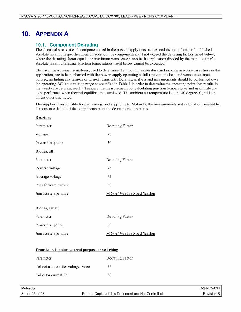
10. APPENDIX A 10.1. Component De-rating The electrical stress of each component used in the power supply must not exceed the manufacturers’ published absolute maximum specifications. In addition, the components must not exceed the de-rating factors listed below, where the de-rating factor equals the maximum worst-case stress in the application divided by the manufacturer’s absolute maximum rating. Junction temperatures listed below cannot be exceeded.
Electrical measurements/analyses, used to determine the junction temperature and maximum worse-case stress in the application, are to be performed with the power supply operating at full (maximum) load and worse-case input voltage, including any turn-on or turn-off transients. Derating analysis and measurements should be performed over the operating AC input voltage range as specified in Table 1 in order to determine the operating point that results in the worst case derating result. Temperature measurements for calculating junction temperatures and useful life are to be performed when thermal equilibrium is achieved. The ambient air temperature is to be 40 degrees C, still air unless otherwise noted.
The supplier is responsible for performing, and supplying to Motorola, the measurements and calculations needed to demonstrate that all of the components meet the de-rating requirements.
Resistors
Parameter De-rating Factor
Voltage .75
Power dissipation .50
Diodes, all
Parameter De-rating Factor
Reverse voltage .75
Average voltage .75
Peak forward current .50
Junction temperature 80% of Vendor Specification
Diodes, zener
Parameter De-rating Factor
Power dissipation .50
Junction temperature 80% of Vendor Specification
Transistor, bipolar, general purpose or switching
Parameter De-rating Factor
Collector-to-emitter voltage, Vceo .75
Collector current, Ic .50

P/S,SWG,90-140VOLTS,57-63HZFREQ,20W,5V/4A, DCX700, LEAD-FREE / ROHS COMPLIANT
Motorola 524475-034 Sheet 26 of 28 Printed Copies of this Document are Not Controlled Revision B
Emitter-base voltage, Veb .75
Power dissipation .50
Junction temperature 80% of Vendor Specification
Transistor, bipolar, power
Parameter De-rating Factor
Collector-to-emitter voltage, Vceo .75
Collector current, Ic .50
Emitter-base voltage, Veb .75
Power dissipation .50
Junction temperature 80% of Vendor Specification
Transistor, low power FET
Parameter De-rating Factor
Drain-source or drain-to-gate voltage, Vds or Vdg .75
Gate current .75
Power dissipation .50
Junction temperature 80% of Vendor Specification
Transistor, power MOSFET
Parameter De-rating Factor
Drain to-source voltage, Vdss .75
Gate-to-source voltage, Vgs .75
Drain current, Id .50
Power dissipation .50
Junction temperature 80% of Vendor Specification
Capacitors, except Aluminum electrolytic
Parameter De-rating Factor
Voltage .50

P/S,SWG,90-140VOLTS,57-63HZFREQ,20W,5V/4A, DCX700, LEAD-FREE / ROHS COMPLIANT
Motorola 524475-034 Sheet 27 of 28 Printed Copies of this Document are Not Controlled Revision B
Capacitors, Aluminum electrolytic
Parameter De-rating Factor
Case temperature .85
Voltage (excluding bulk capacitor) .75
Voltage (bulk capacitor) .96
See section 7.12 for useful life requirements.
IC, PWM, op amps & comparators
Parameter De-rating Factor
Supply voltage, Vcc .75
Input voltage, Vin .75
Power dissipation .75
Junction temperature 80% of Vendor Specification
IC, linear regulator
Parameter De-rating Factor
Input voltage, Vin .75
Power dissipation .50
Junction temperature 80% of Vendor Specification
IC, adjustable precision shunt regulator (example: TL431)
Parameter De-rating Factor
Cathode to anode voltage, Vka .75
Continuous cathode current, Ik .50
Continuous reference input current, Iref .50
Power dissipation .50
Junction temperature 80% of Vendor Specification
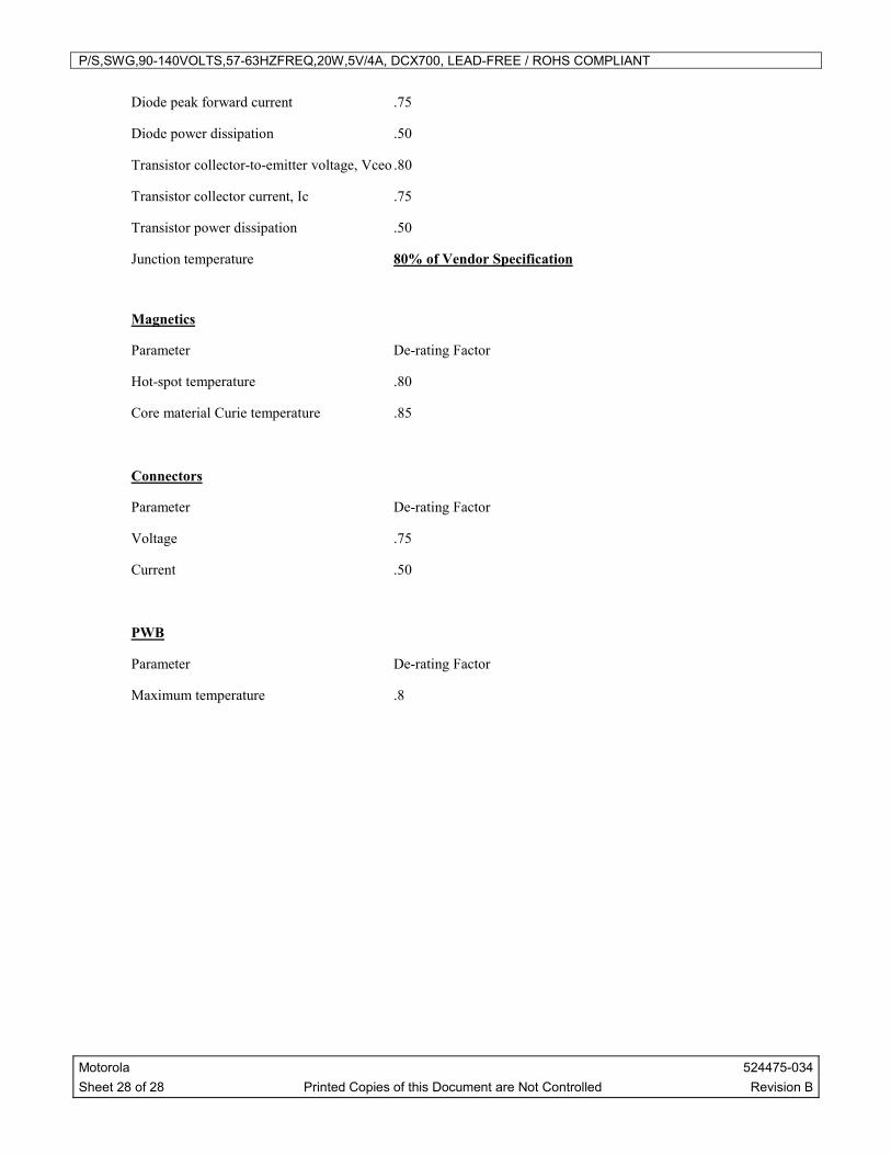
IC, opto-coupler
Parameter De-rating Factor
Diode continuous forward current .75
P/S,SWG,90-140VOLTS,57-63HZFREQ,20W,5V/4A, DCX700, LEAD-FREE / ROHS COMPLIANT
Motorola 524475-034 Sheet 28 of 28 Printed Copies of this Document are Not Controlled Revision B
Diode peak forward current .75
Diode power dissipation .50
Transistor collector-to-emitter voltage, Vceo .80
Transistor collector current, Ic .75
Transistor power dissipation .50
Junction temperature 80% of Vendor Specification
Magnetics
Parameter De-rating Factor
Hot-spot temperature .80
Core material Curie temperature .85
Connectors
Parameter De-rating Factor
Voltage .75
Current .50
PWB
Parameter De-rating Factor
Maximum temperature .8

光寶科技股份有限公司
30

Pb
LITE-ON TECHNOLOGY CORP.
35

43

44
davidchu
David Chu

C
46
davidchu
David Chu


49
davidchu
David Chu