Cu07821 7 culverts new
49
Culverts / Duikers Learning goals on the VLD 1
-
Upload
henk-massink -
Category
Education
-
view
1.265 -
download
1
Transcript of Cu07821 7 culverts new

Culverts / Duikers
Learning goals on the VLD
1

Definition Civil Engineering work for the passage of water. Sometimes lockable, for example related to safety.
Top view
Longitudal sectionCulvert between two waters1
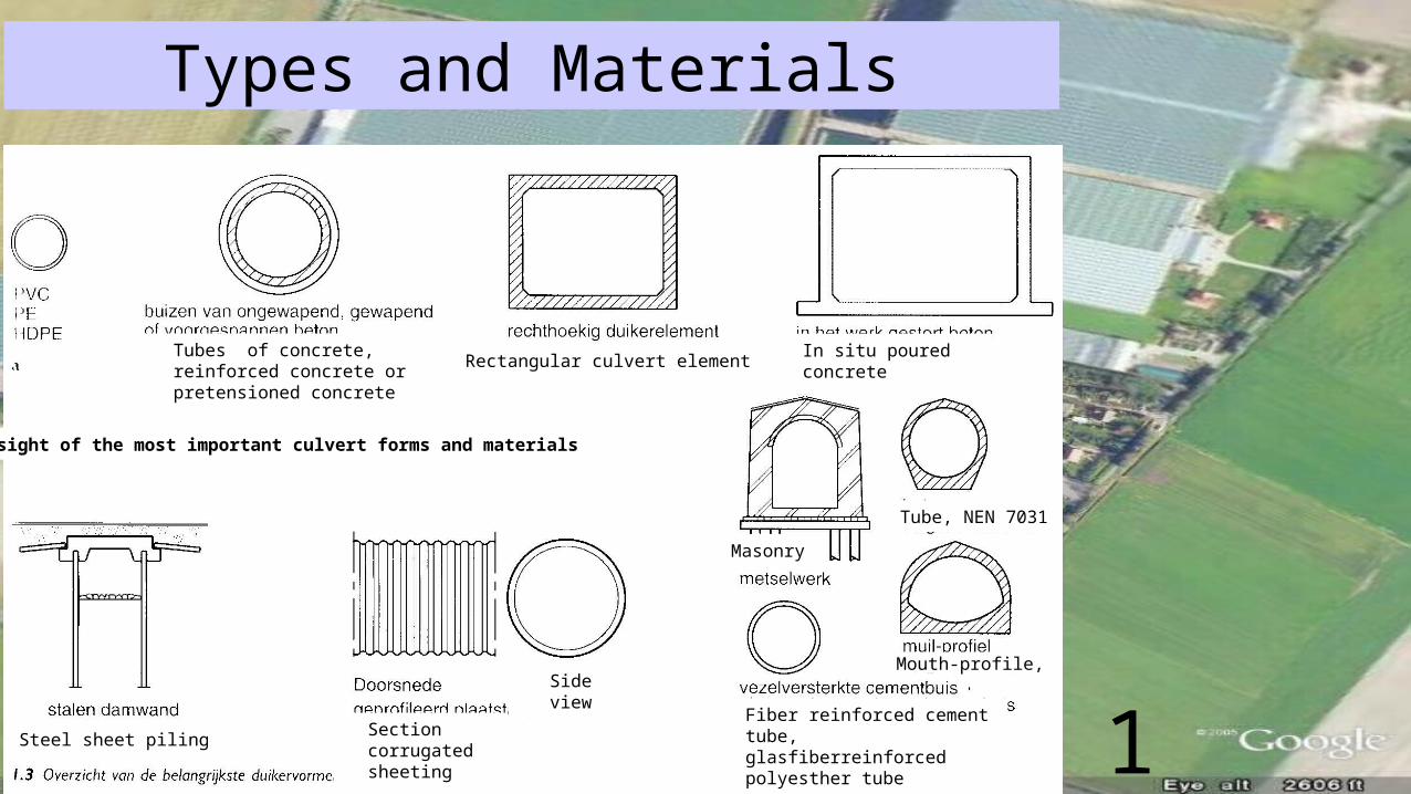
Types and Materials
Tubes of concrete, reinforced concrete or pretensioned concrete
Rectangular culvert element In situ poured concrete
Steel sheet piling Section corrugated sheeting
Side view
Masonry
Tube, NEN 7031
Mouth-profile,
Fiber reinforced cement tube, glasfiberreinforced polyesther tube
Oversight of the most important culvert forms and materials
1

Round concrete tubes with socket and wedge
• Reinforced• Not reinforced
Working length
1
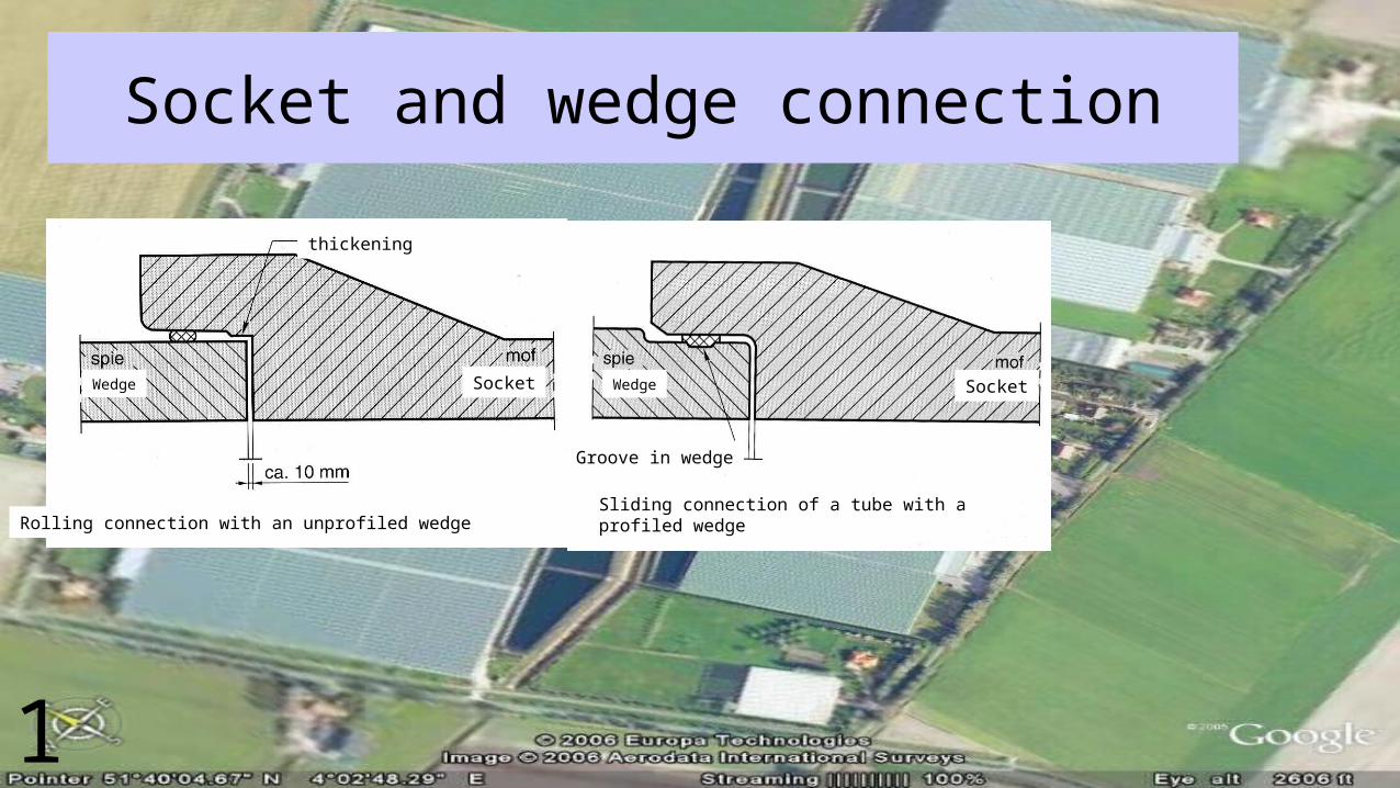
Socket and wedge connection
thickening
Wedge WedgeSocket Socket
Groove in wedge
Rolling connection with an unprofiled wedge Sliding connection of a tube with a profiled wedge
1

Round tubes
www.dehamer.nlwww.wacolingen.nl
Dimensions Mass
Working length
Reinforced and non-reinforced Waco SW-tubes
1

Shallow foundation(fundering op staal)(foundation on sand / gravel)
Bottom of trench free of rocks
Shallow foundation1
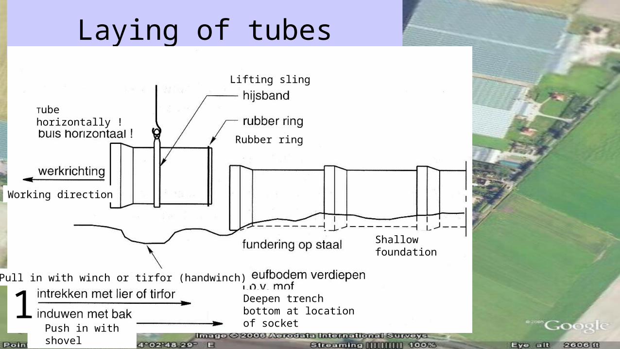
Laying of tubes
Tube horizontally !
Lifting sling
Rubber ring
Shallow foundation
Deepen trench bottom at location of socket
Pull in with winch or tirfor (handwinch)
Push in with shovel
Working direction
1

Foundation on improved soilGrondverbetering
Carrying layer
Dig out and fill in with sand
Foundation on improved soil1
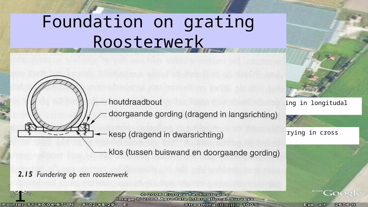
Foundation on gratingRoosterwerk
Bolt for wood
Ongoing girder (carrying in longitudal direction)
Girder (carrying in cross direction)
Block (between tubeside and ongoing girder)
Foundation on grating1
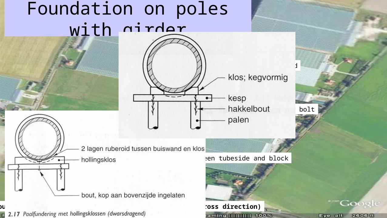
Foundation on poles with girder
Block; wedge formed
Girder
Large bolt
Poles
2 layers of ruberoid between tubeside and block
Hollows block
Bolt, head in wood on topside
Foundation on poles with hollows blocks (carrying in cross direction)1

Foundation on poles with wooden girders and purlins
BlockCarrying girder
Purlin at the location of the sockets
Tubesides free of blocks!
Foundation on poles (carrying cross- and longitudally)1
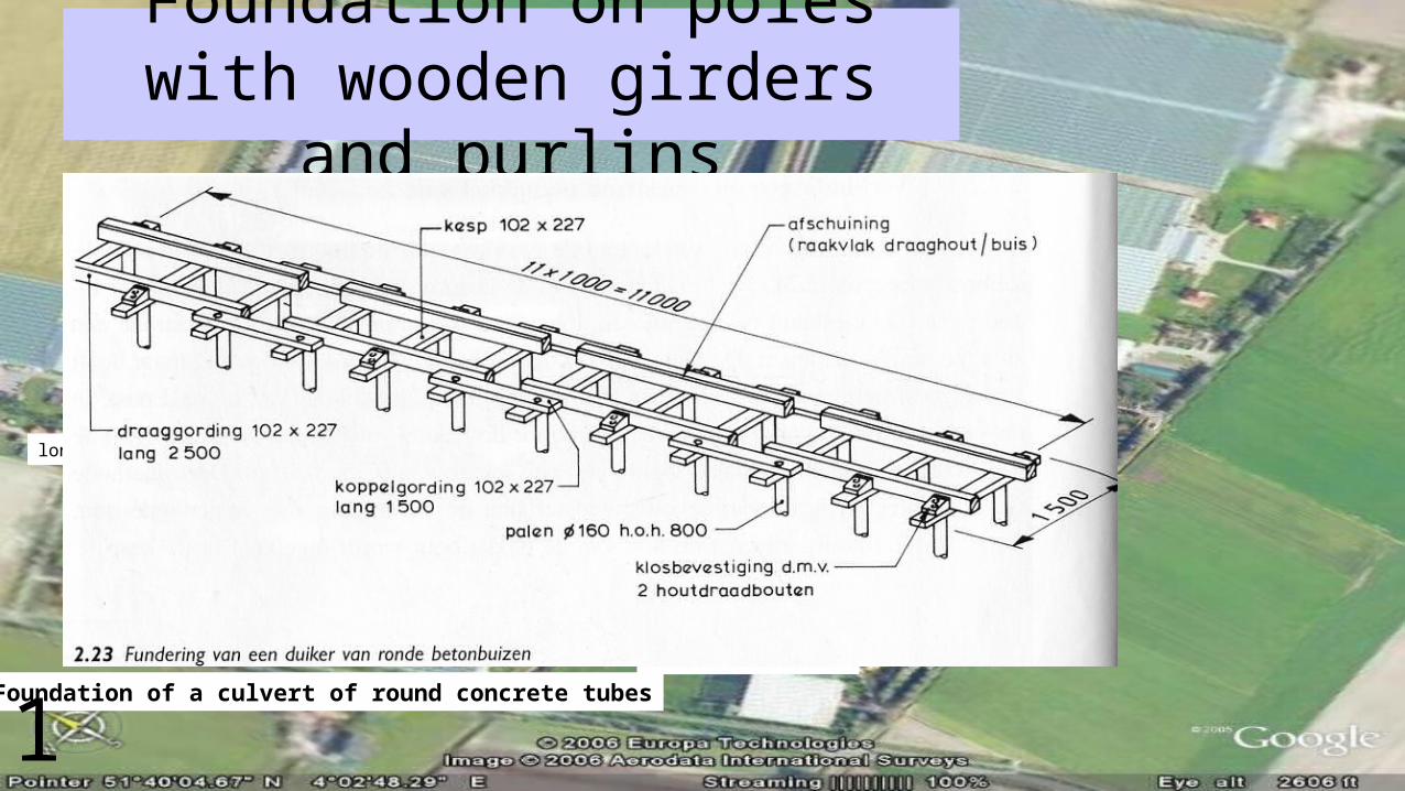
Foundation on poles with wooden girders and purlins
carrying girder
long (length)
Girder
Slanting (interface carrying wood/ tube)
Block connection by means of 2 bolts for wood
Purlin Poles
long (length)
Foundation of a culvert of round concrete tubes
1
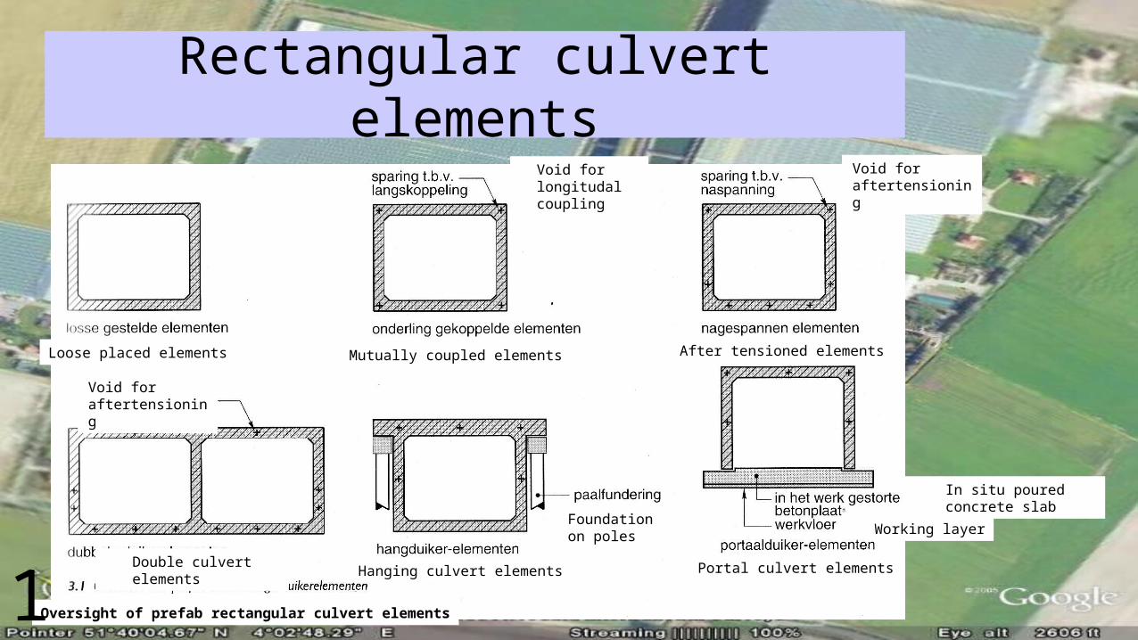
Rectangular culvert elements
Loose placed elements
Void for longitudal coupling
Mutually coupled elements
Void for aftertensioning
After tensioned elements
Void for aftertensioning
Double culvert elements Hanging culvert elements
Foundation on poles
In situ poured concrete slab
Working layer
Portal culvert elements
Oversight of prefab rectangular culvert elements1
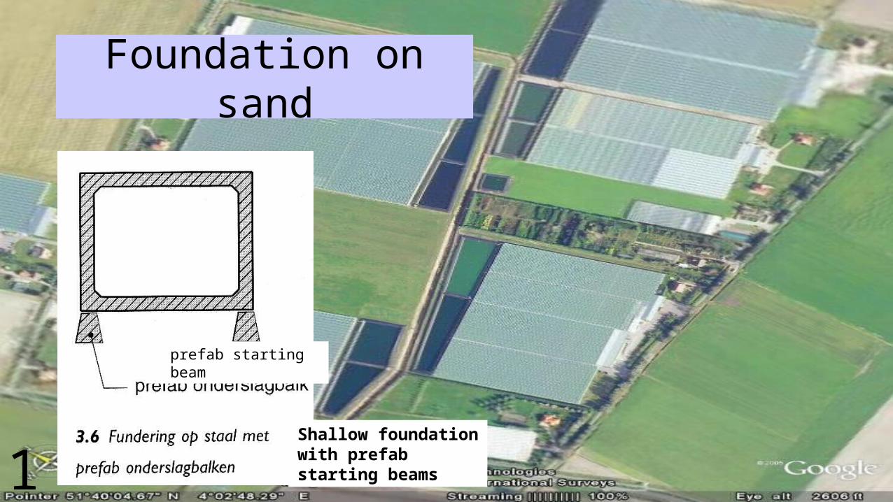
Foundation on sand
prefab starting beam
Shallow foundation with prefab starting beams1
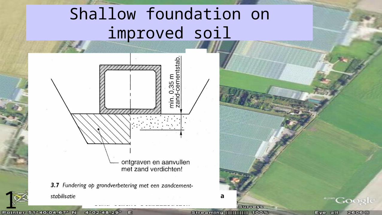
Shallow foundation on improved soil
San
d-ce
men
t st
abili
satio
n
dig out and refill with sand, compress!
Foundation on improved soil with a sand-cement stabilisation1

Foundation on grating
Girder
Cross girder
Deflection
Foundation on grating1

Foundation on concrete slab
Concrete slab
Deflection
Girder
Foundation on a concrete slab
1

Foundation on wooden poles
Longitudal Girder
Cross girder
Foundation on wooden poles1

Foundation on concrete polesImposition
In situ poured concrete (longitudal girder)Punch slab
Cable canal
Concrete pole
Hanging culvert1
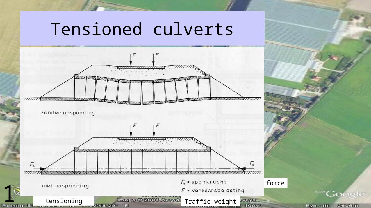
Tensioned culverts
Without tensioning
With tensioning
Tensioning force
Traffic weight1

Rectangular culverts with interlocking
Coupling canal
Lifting hole
Interlocking ends
Large bolt
Poles
Girder
Carrying wood 100x180
Detail interlocking connection
Wedge type endSocket type end Filler
Taping
Mass of cross section of the culvert element 4350 kg; scale 1:40
1
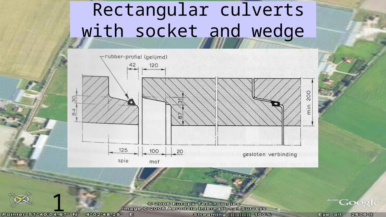
Rectangular culverts with socket and wedge
Rubber profile (glued)
wedge socketClosed connection
1
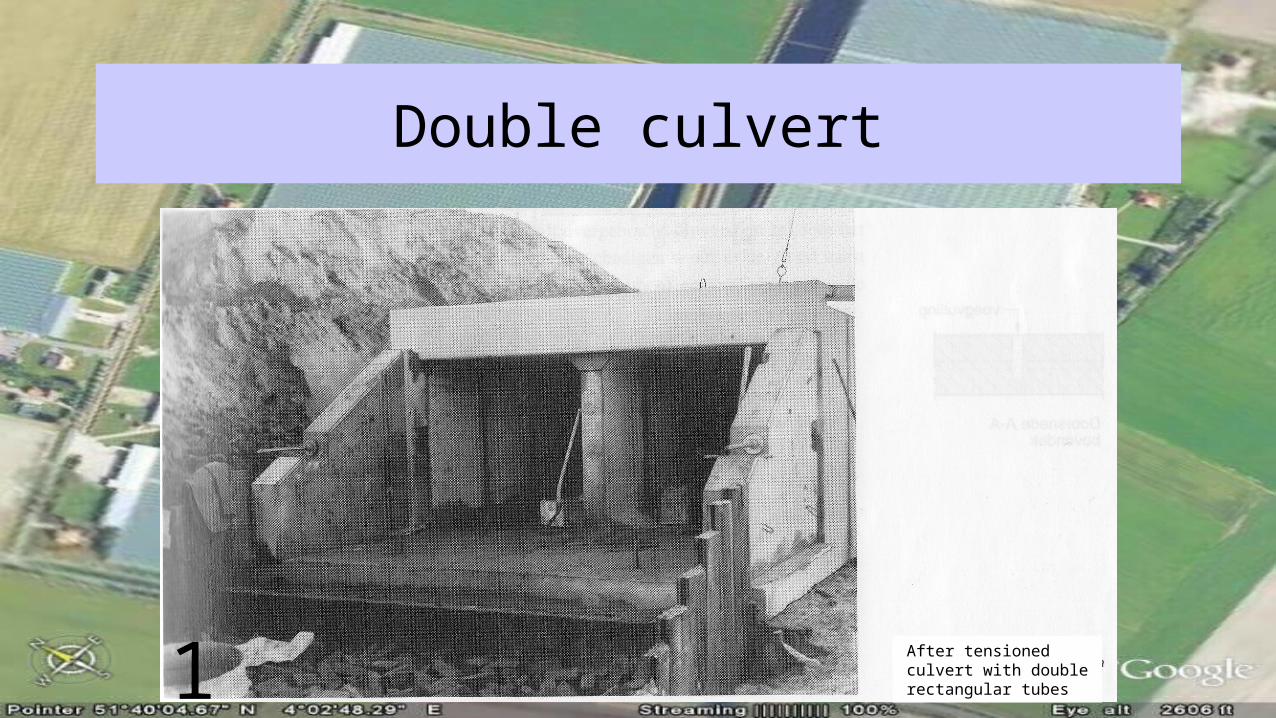
Double culvert
After tensioned culvert with double rectangular tubes1

Hanging culvert
Imposition on fur felt
Longitudal tensioning/cable void
punch- or passage slab
longitudal girder (poured in situ)
poles (reinforced concrete)
1

Portal culverts
Lifting facility
Levelling floor (poured in situ)
Working layer
View Section
Mass of element
Detail interlocking element
Fill joint with sand-cement
Outside measurementTaping
Culvert build of (reversed) U-shaped elements1
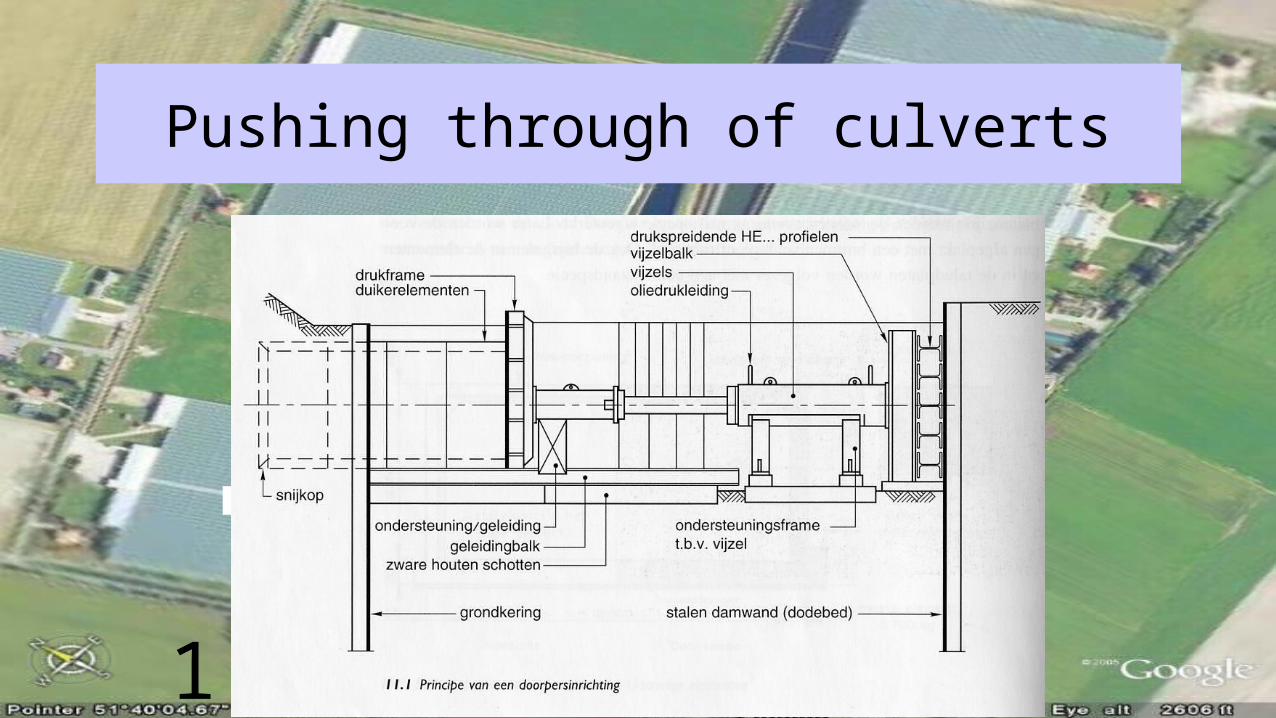
Pushing through of culverts
Pressure frameCulvert elements
Pressure spreading HE-profilesJack beamJacks
Oil pressure tube
Support frame for jacks
Support of conduitConduit beam
Heavy wooden slabs
Soil reversal construction Steel sheet piling (dead weight)
Cutting head
Principle of a push through facility1

Pulled through culverts
jacks
Culvert elements R3
Steel frame
Steel level frame
Steel cutting headPull bars
Pressure girders
Steel sheet piling (dead weight)
Level beams
Pressure frame
Principle of the construction of a pulled through culvert
1
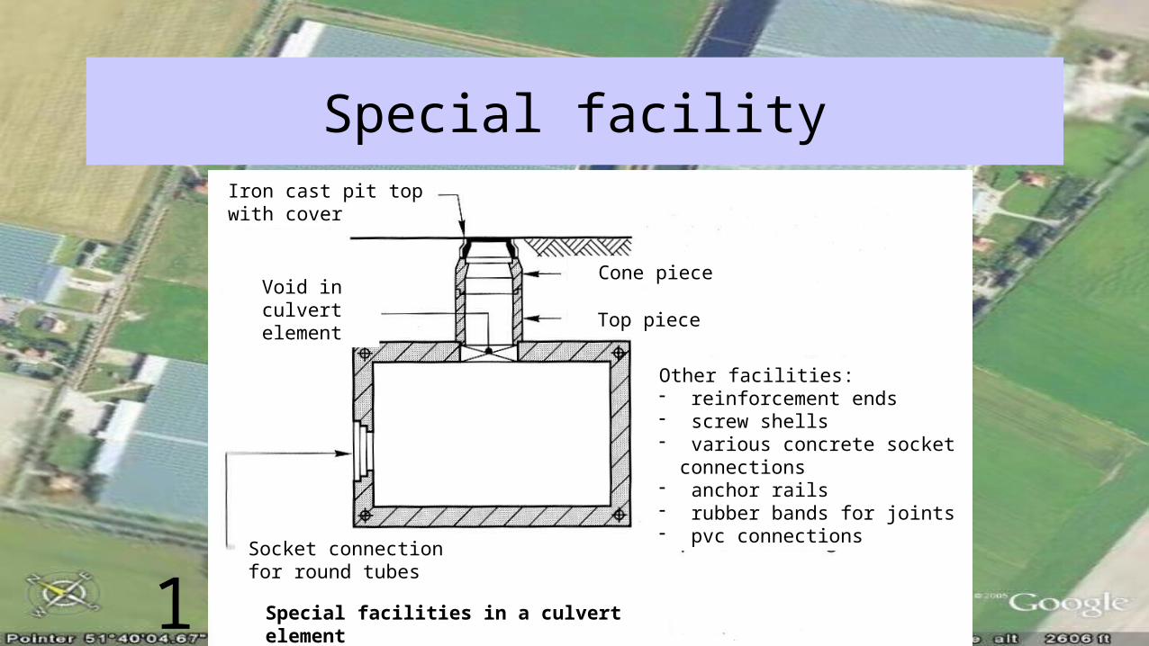
Special facilityIron cast pit top with cover
Cone piece
Top pieceVoid in culvert element
Other facilities:- reinforcement ends- screw shells- various concrete socket
connections- anchor rails- rubber bands for joints- pvc connections
Special facilities in a culvert element
Socket connection for round tubes
1

Trash RackScrew shell for a M10 bolt
Screw shell for a M10 bolt1

Under - and around seepage
(underwashing)New culvert
After some time
Sheet piling1
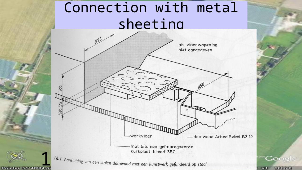
Connection with metal sheeting
Reminder: slab reinforcement is not drawn
Sheet piling Working layer
With bitumen impregnated sheet of cork, width 350
Connection of steel sheeting with a construction on a shallow foundation1
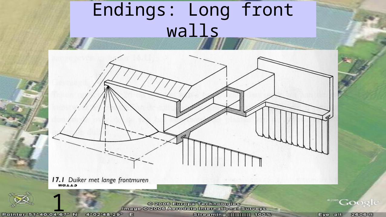
Endings: Long front walls
Culvert with long front walls
1
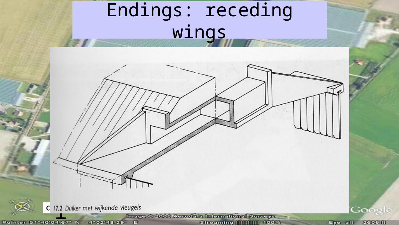
Endings: receding wings
Culvert with receding wings1

Endings: receding wings and return walls
Culvert with receding wings and return walls
1
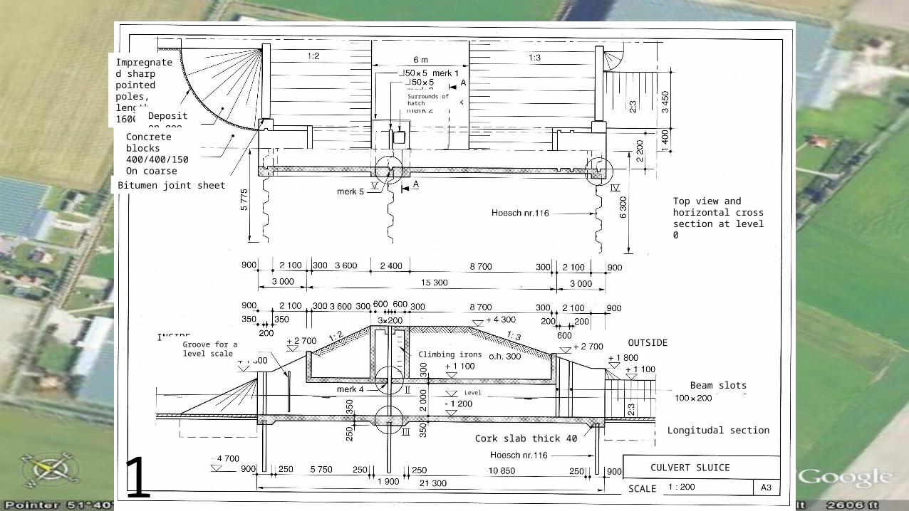
Duikersluis
Impregnated sharp pointed poles, length 1600
Deposit on geo textile
Concrete blocks 400/400/150On coarse gravel
Bitumen joint sheet
Surrounds of hatch
Top view and horizontal cross section at level 0
INSIDE OUTSIDEGroove for a level scale
Climbing irons
Beam slotsLevel
Longitudal sectionCork slab thick 40
CULVERT SLUICE
SCALE1
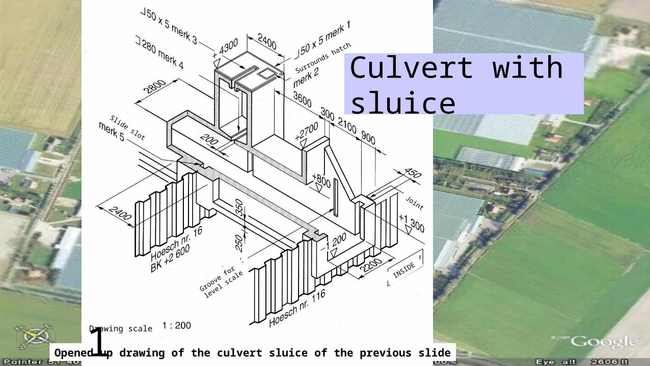
Culvert with sluiceSurrounds hatch
INSIDE
Groove for
level scale
Slide slot
Drawing scale
Opened up drawing of the culvert sluice of the previous slide
Joint
1

Culvert made of metal sheeting
Cross section
Front view without earthing
Front view with earthing
Railing is not drawn
Impregnated sharp pointed poles
1

Culvert made of metal sheeting
Top view with earthing Top view without earthing
Punch slabs
Ramming plan steel sheet piling
Steel sheet piling
Longitudal section
Concrete blocks on gravel Rubble (broken concrete and masonry) on polyetheen fabric1

Culvert of corrugated steel tubes
“Armco” culvert1

Culvert made of masonry
Special layer
Segment curve
Pla
ster
ed s
ides
poles
girdersflooring
Sliding woods
Bottom levelled Bottom curved
Cross section of a culvert made of masonry1

Floating
Steel works to be galvanized
Side view
boltnut
1
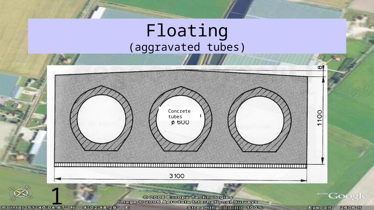
Floating(aggravated tubes)
Concrete tubes
1

Floating“concrete” anchors Anchor blocks
“concrete” anchors Prefab anchor block
Tensioning rods
Tensioning rods
Polyetheen plating1

Dilatation joints
Dilatation joint width 300
Culvert floor slabSealer or glue
Bitumen joint sheeting or EPS
2xbituminateShallow foundation
Foundation on poles
2xbituminateBitumen joint sheeting or EPS
Culvert floor slab
Dilatation joints with sealed joints1

Receiving- and gravel beds
Ground water level fall
Dumping bed Receiving bed
General: σsoil = σgrain + σwater
Ground level
Ground water level
Water over pressure
turbulence
excavation
Scheme of weights/pressures working on the bottom defence1
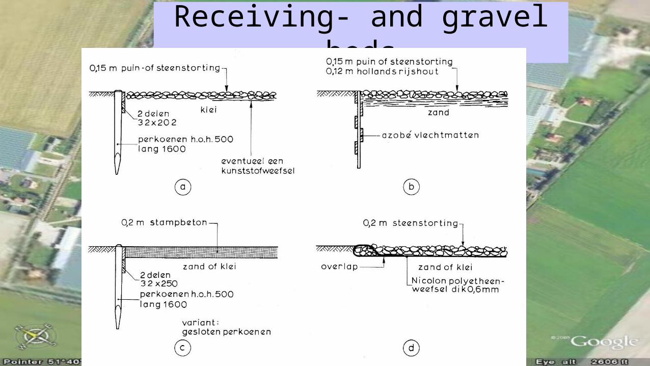
Receiving- and gravel bedsrubble (broken concrete/ broken masonry) or broken natural stone dump
Rubble or natural stone dump
Willow branches
planks clay
poles
long
Situational a synthetic fabric
sand
Azobe (tropical wood) twined mat
Concrete layer Broken natural stone dump
Sand or clay Sand or clayplanks
poles
long
Variant: row of closely rowed poles
Doubled layer
Nicolon polyetheen fabric thick 0,6 mmm
1

Receiving- and gravel bedsConcrete blocks
gravelclay
Stone masonryRubble dump (filling layers)
Layed layers
Sand or clay
Sheeting thick 72 long 2000Creosoted pine
Sheeting thick 72 long 2300
Reinforced concrete
Azobe sheeting
Stone masonry
Rubble dump
Reed on 0,3 m clayWillow branches
sand
sheeting
sand
1
Prefab or in situ poured concrete?
1