Corrosion of Aluminium-clad Spent Research Reactor Fuel in ... · Corrosion of Aluminium-clad Spent...
12
Corrosion of Aluminium-clad Spent Research Reactor Fuel in Wet Storage L.Ramanathan 1 , R.Haddad 2 , P.Adelfang 3 and I.Ritchie 3 (1) Instituto de Pesquisas Energéticas e Nucleares, IPEN, São Paulo, Brazil. (2) Comisión Nacional de Energía Atómica, CNEA, Buenos Aires, Argentina. (3) International Atomic Energy Agency, IAEA, Vienna, Austria. Abstract A variety of spent research reactor (RR) fuels with different fuel meats, different geometries and different U235 enrichments are presently stored under water in basins throughout the world while awaiting final disposition or shipment to the USA or to the Russian Federation. More than 90% of this fuel is clad in aluminium or its alloy and are susceptible to corrosion in water of less than optimum quality. Concerns related to corrosion of the Al-clad fuels in storage lead to the implementation of a coordinated research project (CRP) “Corrosion of research reactor aluminium-clad spent fuel in water” by the IAEA and RR spent fuel corrosion studies within the IAEA coordinated Regional Project for Latin America (RLA) on “Research Reactor Spent Fuel Management”. The activities within the two projects consisted of exposing standard racks of coupons of a variety of aluminium alloys in different configurations to spent fuel storage basins in 14 participating countries of the CRP and 5 participating countries in the RLA project. The coupons were evaluated after predetermined exposures times and during the whole surveillance period the storage basin water parameters were monitored periodically. The Al alloys selected for testing were representative of typical RR cladding alloys, handling tools and storage racks. The influence of Al alloy composition, galvanic effects (Al alloy/stainless steel), crevice effects, presence of surface oxide, mechanically damaged surface oxide, water parameters (mainly, pH, conductivity, chloride ions), coupon orientation, presence of settled solids on coupon surfaces on the corrosion of Al alloys were investigated. Pitting was found to be the main form of corrosion and the factors that influenced pitting corrosion of the coupons in the storage basins were water conductivity, chloride ion content, formation of galvanic couples with stainless steel rack supports and settled solid particles. Complementary tests were carried to determine the composition and nature of the settled solids. Further laboratory tests were carried out to determine the effect of settled solid composition on the nature and mechanism of corrosion. Key words: Corrosion, spent fuel, research reactor, wet storage, aluminium alloy, pitting, water quality.
Transcript of Corrosion of Aluminium-clad Spent Research Reactor Fuel in ... · Corrosion of Aluminium-clad Spent...
Corrosion of Aluminium-clad Spent Research Reactor Fuel in
Wet Storage
L.Ramanathan1, R.Haddad2, P.Adelfang3 and I.Ritchie3
(1) Instituto de Pesquisas Energéticas e Nucleares, IPEN, São Paulo, Brazil. (2) Comisión Nacional de Energía Atómica, CNEA, Buenos Aires, Argentina.
(3) International Atomic Energy Agency, IAEA, Vienna, Austria.
Abstract
A variety of spent research reactor (RR) fuels with different fuel meats, different geometries and different U235 enrichments are presently stored under water in basins throughout the world while awaiting final disposition or shipment to the USA or to the Russian Federation. More than 90% of this fuel is clad in aluminium or its alloy and are susceptible to corrosion in water of less than optimum quality. Concerns related to corrosion of the Al-clad fuels in storage lead to the implementation of a coordinated research project (CRP) “Corrosion of research reactor aluminium-clad spent fuel in water” by the IAEA and RR spent fuel corrosion studies within the IAEA coordinated Regional Project for Latin America (RLA) on “Research Reactor Spent Fuel Management”. The activities within the two projects consisted of exposing standard racks of coupons of a variety of aluminium alloys in different configurations to spent fuel storage basins in 14 participating countries of the CRP and 5 participating countries in the RLA project. The coupons were evaluated after predetermined exposures times and during the whole surveillance period the storage basin water parameters were monitored periodically. The Al alloys selected for testing were representative of typical RR cladding alloys, handling tools and storage racks. The influence of Al alloy composition, galvanic effects (Al alloy/stainless steel), crevice effects, presence of surface oxide, mechanically damaged surface oxide, water parameters (mainly, pH, conductivity, chloride ions), coupon orientation, presence of settled solids on coupon surfaces on the corrosion of Al alloys were investigated. Pitting was found to be the main form of corrosion and the factors that influenced pitting corrosion of the coupons in the storage basins were water conductivity, chloride ion content, formation of galvanic couples with stainless steel rack supports and settled solid particles. Complementary tests were carried to determine the composition and nature of the settled solids. Further laboratory tests were carried out to determine the effect of settled solid composition on the nature and mechanism of corrosion. Key words: Corrosion, spent fuel, research reactor, wet storage, aluminium alloy, pitting, water quality.
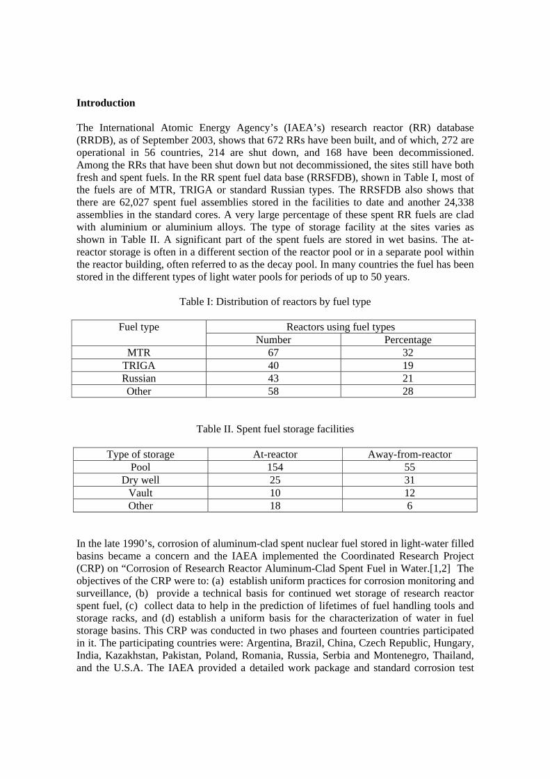
Introduction The International Atomic Energy Agency’s (IAEA’s) research reactor (RR) database (RRDB), as of September 2003, shows that 672 RRs have been built, and of which, 272 are operational in 56 countries, 214 are shut down, and 168 have been decommissioned. Among the RRs that have been shut down but not decommissioned, the sites still have both fresh and spent fuels. In the RR spent fuel data base (RRSFDB), shown in Table I, most of the fuels are of MTR, TRIGA or standard Russian types. The RRSFDB also shows that there are 62,027 spent fuel assemblies stored in the facilities to date and another 24,338 assemblies in the standard cores. A very large percentage of these spent RR fuels are clad with aluminium or aluminium alloys. The type of storage facility at the sites varies as shown in Table II. A significant part of the spent fuels are stored in wet basins. The at- reactor storage is often in a different section of the reactor pool or in a separate pool within the reactor building, often referred to as the decay pool. In many countries the fuel has been stored in the different types of light water pools for periods of up to 50 years.
Table I: Distribution of reactors by fuel type
Fuel type Reactors using fuel types Number Percentage
MTR 67 32 TRIGA 40 19 Russian 43 21 Other 58 28
Table II. Spent fuel storage facilities
Type of storage At-reactor Away-from-reactor Pool 154 55
Dry well 25 31 Vault 10 12 Other 18 6
In the late 1990’s, corrosion of aluminum-clad spent nuclear fuel stored in light-water filled basins became a concern and the IAEA implemented the Coordinated Research Project (CRP) on “Corrosion of Research Reactor Aluminum-Clad Spent Fuel in Water.[1,2] The objectives of the CRP were to: (a) establish uniform practices for corrosion monitoring and surveillance, (b) provide a technical basis for continued wet storage of research reactor spent fuel, (c) collect data to help in the prediction of lifetimes of fuel handling tools and storage racks, and (d) establish a uniform basis for the characterization of water in fuel storage basins. This CRP was conducted in two phases and fourteen countries participated in it. The participating countries were: Argentina, Brazil, China, Czech Republic, Hungary, India, Kazakhstan, Pakistan, Poland, Romania, Russia, Serbia and Montenegro, Thailand, and the U.S.A. The IAEA provided a detailed work package and standard corrosion test
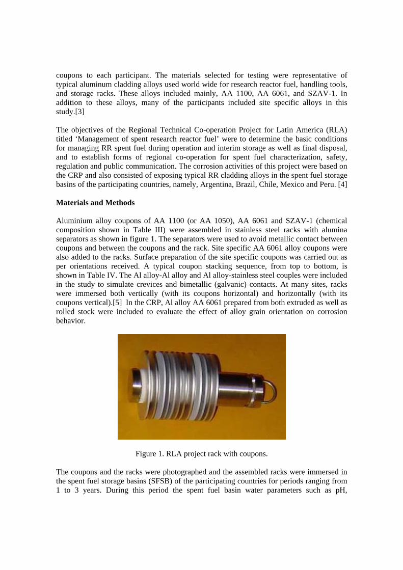
coupons to each participant. The materials selected for testing were representative of typical aluminum cladding alloys used world wide for research reactor fuel, handling tools, and storage racks. These alloys included mainly, AA 1100, AA 6061, and SZAV-1. In addition to these alloys, many of the participants included site specific alloys in this study.[3] The objectives of the Regional Technical Co-operation Project for Latin America (RLA) titled ‘Management of spent research reactor fuel’ were to determine the basic conditions for managing RR spent fuel during operation and interim storage as well as final disposal, and to establish forms of regional co-operation for spent fuel characterization, safety, regulation and public communication. The corrosion activities of this project were based on the CRP and also consisted of exposing typical RR cladding alloys in the spent fuel storage basins of the participating countries, namely, Argentina, Brazil, Chile, Mexico and Peru. [4] Materials and Methods Aluminium alloy coupons of AA 1100 (or AA 1050), AA 6061 and SZAV-1 (chemical composition shown in Table III) were assembled in stainless steel racks with alumina separators as shown in figure 1. The separators were used to avoid metallic contact between coupons and between the coupons and the rack. Site specific AA 6061 alloy coupons were also added to the racks. Surface preparation of the site specific coupons was carried out as per orientations received. A typical coupon stacking sequence, from top to bottom, is shown in Table IV. The Al alloy-Al alloy and Al alloy-stainless steel couples were included in the study to simulate crevices and bimetallic (galvanic) contacts. At many sites, racks were immersed both vertically (with its coupons horizontal) and horizontally (with its coupons vertical).[5] In the CRP, Al alloy AA 6061 prepared from both extruded as well as rolled stock were included to evaluate the effect of alloy grain orientation on corrosion behavior.
Figure 1. RLA project rack with coupons. The coupons and the racks were photographed and the assembled racks were immersed in the spent fuel storage basins (SFSB) of the participating countries for periods ranging from 1 to 3 years. During this period the spent fuel basin water parameters such as pH,
conductivity, chloride content, temperature and other ions that were site specific were monitored periodically. Overall the quality of basin water at the different sites varied significantly, from very good to very bad. Table-V lists some of the basin water parameters at some sites. Graphs of variations in the water parameters were also plotted to help correlate coupon corrosion with water parameters. After pre-determined periods the racks were withdrawn from the basins, were photographed and the extent of corrosion of the coupons evaluated following standard procedures outlined in the CRP Test Protocol. The Test Protocol included measurement of pH in the crevices of the crevice and bimetallic couples. The CRP coupons were examined in an optical microscope and the RLA project coupons, in an optical microscope coupled to an image analysis system.
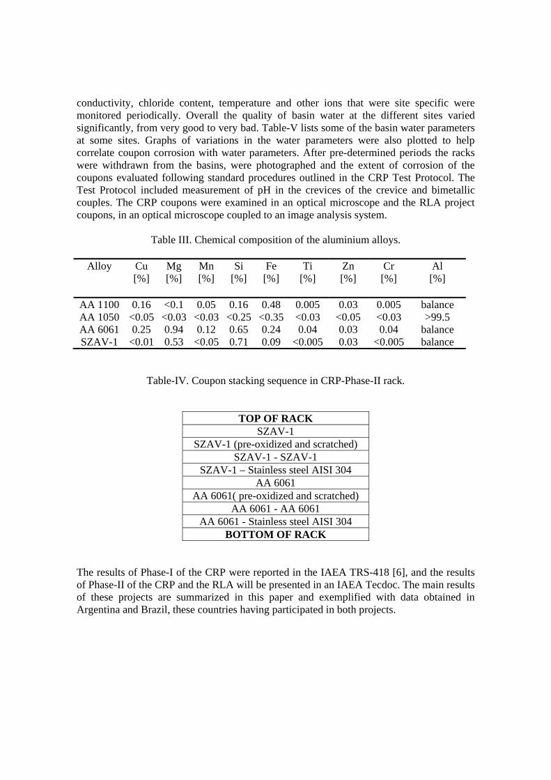
Table III. Chemical composition of the aluminium alloys.
Alloy Cu [%]
Mg [%]
Mn [%]
Si [%]
Fe [%]
Ti [%]
Zn [%]
Cr [%]
Al [%]
AA 1100 0.16 <0.1 0.05 0.16 0.48 0.005 0.03 0.005 balance AA 1050 <0.05 <0.03 <0.03 <0.25 <0.35 <0.03 <0.05 <0.03 >99.5 AA 6061 0.25 0.94 0.12 0.65 0.24 0.04 0.03 0.04 balance SZAV-1 <0.01 0.53 <0.05 0.71 0.09 <0.005 0.03 <0.005 balance
Table-IV. Coupon stacking sequence in CRP-Phase-II rack.
TOP OF RACK SZAV-1
SZAV-1 (pre-oxidized and scratched) SZAV-1 - SZAV-1
SZAV-1 – Stainless steel AISI 304 AA 6061
AA 6061( pre-oxidized and scratched) AA 6061 - AA 6061
AA 6061 - Stainless steel AISI 304 BOTTOM OF RACK
The results of Phase-I of the CRP were reported in the IAEA TRS-418 [6], and the results of Phase-II of the CRP and the RLA will be presented in an IAEA Tecdoc. The main results of these projects are summarized in this paper and exemplified with data obtained in Argentina and Brazil, these countries having participated in both projects.
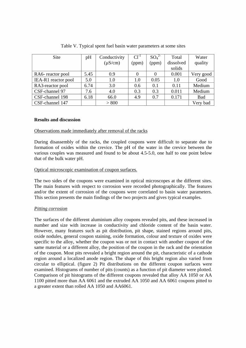
Table V. Typical spent fuel basin water parameters at some sites
Site pH Conductivity (µS/cm)
Cl-1 (ppm)
SO42-
(ppm) Total
dissolved solids
Water quality
RA6- reactor pool 5.45 0.9 0 0 0.001 Very goodIEA-R1 reactor pool 5.0 1.0 1.0 0.05 1.0 Good RA3-reactor pool 6.74 3.0 0.6 0.1 0.11 Medium CSF-channel 97 7.6 4.0 0.3 0.3 0.011 Medium CSF-channel 198 6.18 66.0 4.9 0.7 0.171 Bad CSF-channel 147 > 800 Very bad Results and discussion Observations made immediately after removal of the racks During disassembly of the racks, the coupled coupons were difficult to separate due to formation of oxides within the crevice. The pH of the water in the crevice between the various couples was measured and found to be about 4.5-5.0, one half to one point below that of the bulk water pH. Optical microscopic examination of coupon surfaces. The two sides of the coupons were examined in optical microscopes at the different sites. The main features with respect to corrosion were recorded photographically. The features and/or the extent of corrosion of the coupons were correlated to basin water parameters. This section presents the main findings of the two projects and gives typical examples. Pitting corrosion The surfaces of the different aluminium alloy coupons revealed pits, and these increased in number and size with increase in conductivity and chloride content of the basin water. However, many features such as pit distribution, pit shape, stained regions around pits, oxide nodules, general coupon staining, oxide formation, colour and texture of oxides were specific to the alloy, whether the coupon was or not in contact with another coupon of the same material or a different alloy, the position of the coupon in the rack and the orientation of the coupon. Most pits revealed a bright region around the pit, characteristic of a cathode region around a localized anode region. The shape of this bright region also varied from circular to elliptical. (figure 2) Pit distributions on the different coupon surfaces were examined. Histograms of number of pits (counts) as a function of pit diameter were plotted. Comparison of pit histograms of the different coupons revealed that alloy AA 1050 or AA 1100 pitted more than AA 6061 and the extruded AA 1050 and AA 6061 coupons pitted to a greater extent than rolled AA 1050 and AA6061.
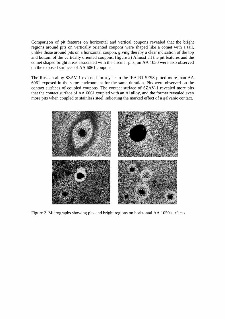
Comparison of pit features on horizontal and vertical coupons revealed that the bright regions around pits on vertically oriented coupons were shaped like a comet with a tail, unlike those around pits on a horizontal coupon, giving thereby a clear indication of the top and bottom of the vertically oriented coupons. (figure 3) Almost all the pit features and the comet shaped bright areas associated with the circular pits, on AA 1050 were also observed on the exposed surfaces of AA 6061 coupons. The Russian alloy SZAV-1 exposed for a year to the IEA-R1 SFSS pitted more than AA 6061 exposed in the same environment for the same duration. Pits were observed on the contact surfaces of coupled coupons. The contact surface of SZAV-1 revealed more pits that the contact surface of AA 6061 coupled with an Al alloy, and the former revealed even more pits when coupled to stainless steel indicating the marked effect of a galvanic contact.
Figure 2. Micrographs showing pits and bright regions on horizontal AA 1050 surfaces.
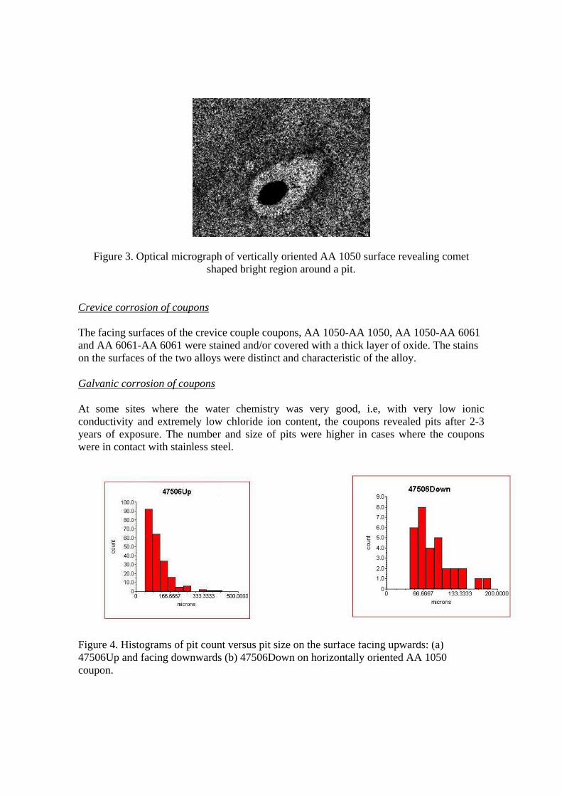
Figure 3. Optical micrograph of vertically oriented AA 1050 surface revealing comet shaped bright region around a pit.
Crevice corrosion of coupons The facing surfaces of the crevice couple coupons, AA 1050-AA 1050, AA 1050-AA 6061 and AA 6061-AA 6061 were stained and/or covered with a thick layer of oxide. The stains on the surfaces of the two alloys were distinct and characteristic of the alloy. Galvanic corrosion of coupons At some sites where the water chemistry was very good, i.e, with very low ionic conductivity and extremely low chloride ion content, the coupons revealed pits after 2-3 years of exposure. The number and size of pits were higher in cases where the coupons were in contact with stainless steel.
Figure 4. Histograms of pit count versus pit size on the surface facing upwards: (a) 47506Up and facing downwards (b) 47506Down on horizontally oriented AA 1050 coupon.
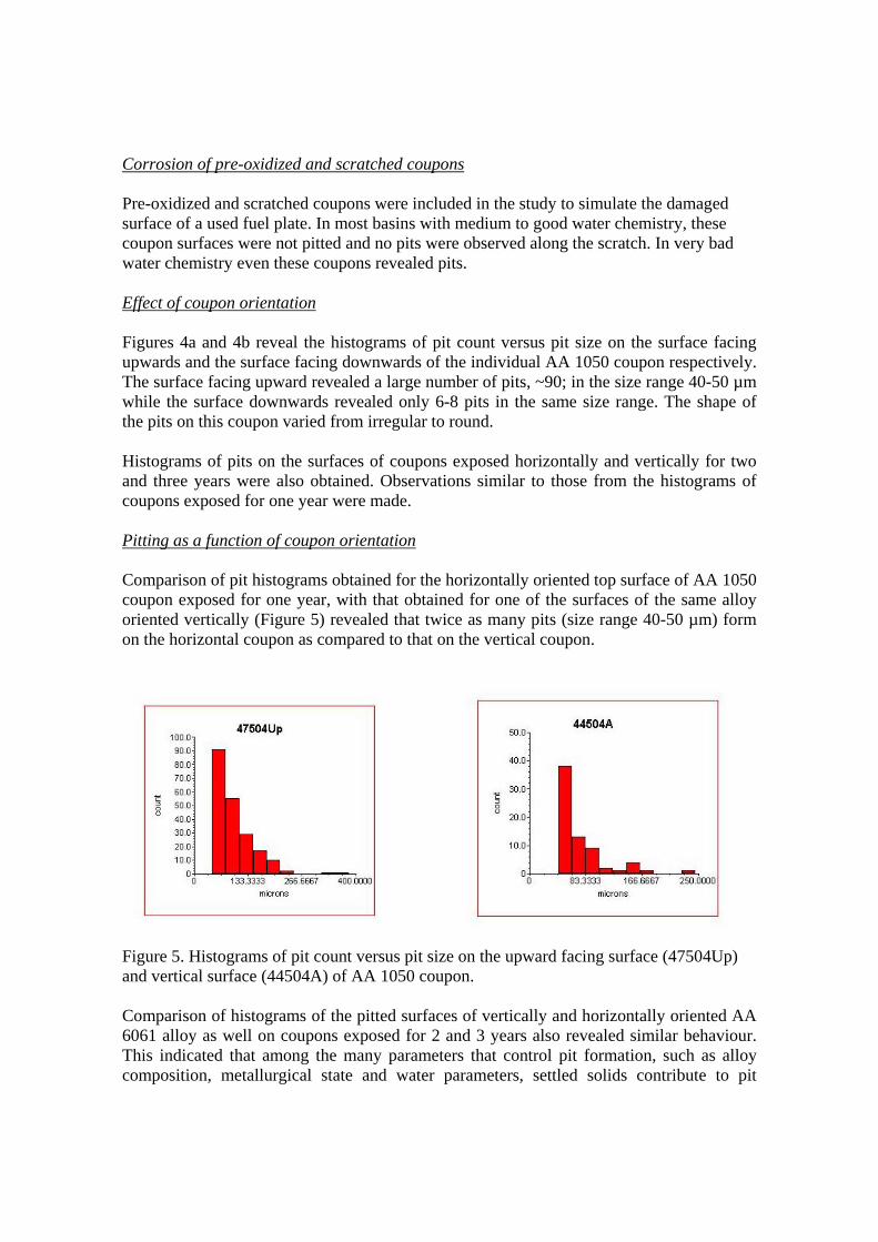
Corrosion of pre-oxidized and scratched coupons Pre-oxidized and scratched coupons were included in the study to simulate the damaged surface of a used fuel plate. In most basins with medium to good water chemistry, these coupon surfaces were not pitted and no pits were observed along the scratch. In very bad water chemistry even these coupons revealed pits. Effect of coupon orientation Figures 4a and 4b reveal the histograms of pit count versus pit size on the surface facing upwards and the surface facing downwards of the individual AA 1050 coupon respectively. The surface facing upward revealed a large number of pits, ~90; in the size range 40-50 µm while the surface downwards revealed only 6-8 pits in the same size range. The shape of the pits on this coupon varied from irregular to round. Histograms of pits on the surfaces of coupons exposed horizontally and vertically for two and three years were also obtained. Observations similar to those from the histograms of coupons exposed for one year were made. Pitting as a function of coupon orientation Comparison of pit histograms obtained for the horizontally oriented top surface of AA 1050 coupon exposed for one year, with that obtained for one of the surfaces of the same alloy oriented vertically (Figure 5) revealed that twice as many pits (size range 40-50 µm) form on the horizontal coupon as compared to that on the vertical coupon. Figure 5. Histograms of pit count versus pit size on the upward facing surface (47504Up) and vertical surface (44504A) of AA 1050 coupon. Comparison of histograms of the pitted surfaces of vertically and horizontally oriented AA 6061 alloy as well on coupons exposed for 2 and 3 years also revealed similar behaviour. This indicated that among the many parameters that control pit formation, such as alloy composition, metallurgical state and water parameters, settled solids contribute to pit
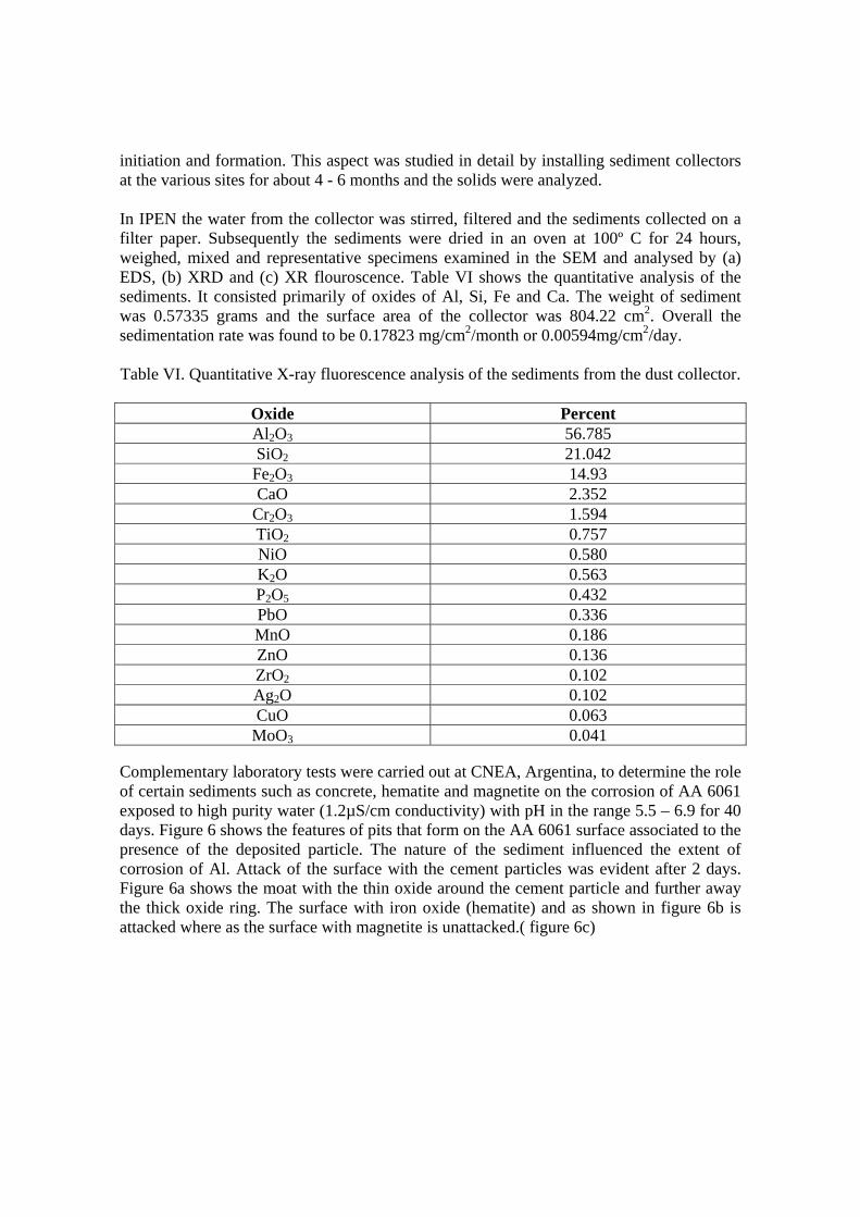
initiation and formation. This aspect was studied in detail by installing sediment collectors at the various sites for about 4 - 6 months and the solids were analyzed. In IPEN the water from the collector was stirred, filtered and the sediments collected on a filter paper. Subsequently the sediments were dried in an oven at 100º C for 24 hours, weighed, mixed and representative specimens examined in the SEM and analysed by (a) EDS, (b) XRD and (c) XR flouroscence. Table VI shows the quantitative analysis of the sediments. It consisted primarily of oxides of Al, Si, Fe and Ca. The weight of sediment was 0.57335 grams and the surface area of the collector was 804.22 cm2. Overall the sedimentation rate was found to be 0.17823 mg/cm2/month or 0.00594mg/cm2/day. Table VI. Quantitative X-ray fluorescence analysis of the sediments from the dust collector.
Oxide Percent Al2O3 56.785 SiO2 21.042 Fe2O3 14.93 CaO 2.352
Cr2O3 1.594 TiO2 0.757 NiO 0.580 K2O 0.563 P2O5 0.432 PbO 0.336 MnO 0.186 ZnO 0.136 ZrO2 0.102 Ag2O 0.102 CuO 0.063
MoO3 0.041 Complementary laboratory tests were carried out at CNEA, Argentina, to determine the role of certain sediments such as concrete, hematite and magnetite on the corrosion of AA 6061 exposed to high purity water (1.2µS/cm conductivity) with pH in the range 5.5 – 6.9 for 40 days. Figure 6 shows the features of pits that form on the AA 6061 surface associated to the presence of the deposited particle. The nature of the sediment influenced the extent of corrosion of Al. Attack of the surface with the cement particles was evident after 2 days. Figure 6a shows the moat with the thin oxide around the cement particle and further away the thick oxide ring. The surface with iron oxide (hematite) and as shown in figure 6b is attacked where as the surface with magnetite is unattacked.( figure 6c)
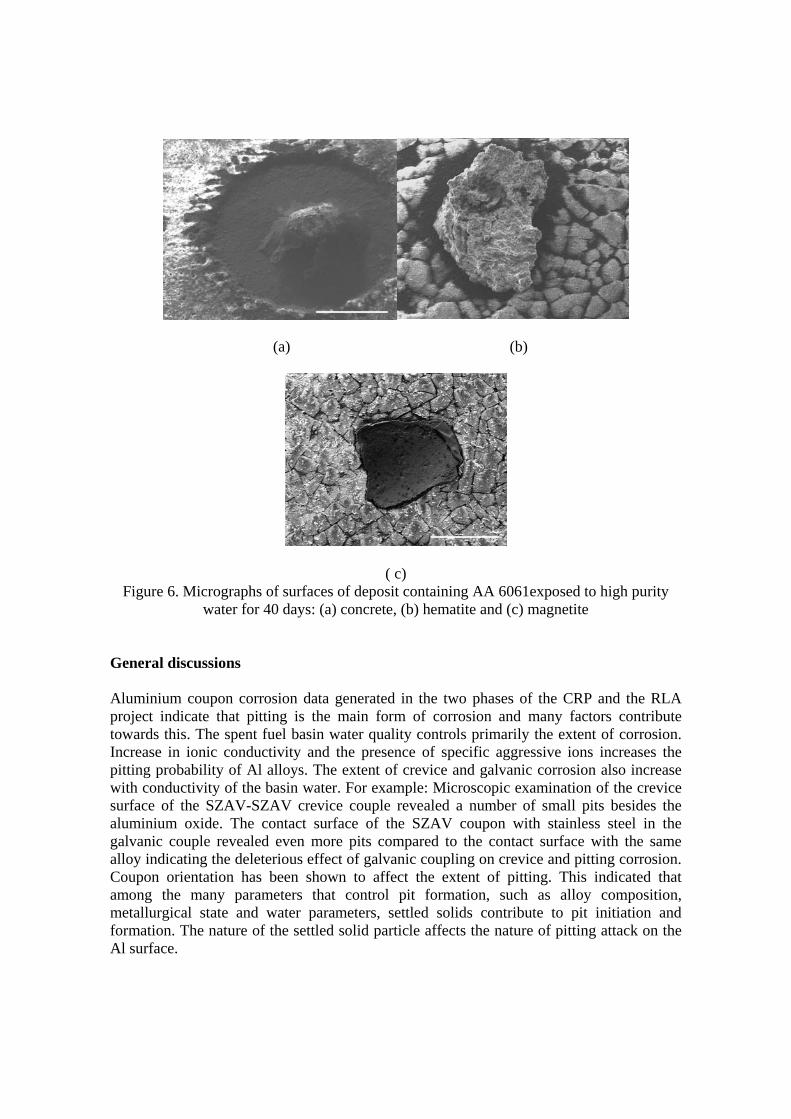
(a) (b)
( c) Figure 6. Micrographs of surfaces of deposit containing AA 6061exposed to high purity
water for 40 days: (a) concrete, (b) hematite and (c) magnetite General discussions Aluminium coupon corrosion data generated in the two phases of the CRP and the RLA project indicate that pitting is the main form of corrosion and many factors contribute towards this. The spent fuel basin water quality controls primarily the extent of corrosion. Increase in ionic conductivity and the presence of specific aggressive ions increases the pitting probability of Al alloys. The extent of crevice and galvanic corrosion also increase with conductivity of the basin water. For example: Microscopic examination of the crevice surface of the SZAV-SZAV crevice couple revealed a number of small pits besides the aluminium oxide. The contact surface of the SZAV coupon with stainless steel in the galvanic couple revealed even more pits compared to the contact surface with the same alloy indicating the deleterious effect of galvanic coupling on crevice and pitting corrosion. Coupon orientation has been shown to affect the extent of pitting. This indicated that among the many parameters that control pit formation, such as alloy composition, metallurgical state and water parameters, settled solids contribute to pit initiation and formation. The nature of the settled solid particle affects the nature of pitting attack on the Al surface.
Conclusions
1. Coupons exposed to the spent fuel basins revealed that pitting was the main form of corrosion.
2. The top surface of the horizontally oriented coupons pitted more than the bottom facing surface. The extent of pitting on the top surface of horizontal coupons decreased with change in position of the coupon from top to bottom in the rack.
3. The two sides of vertically oriented coupons of different alloys pitted to the same extent.
4. The extent of pitting of vertically oriented coupons was considerably less than that of the horizontally oriented coupons indicating that pit formation is influenced by, among other factors, settled solid particles on the coupon surface.
5. Both the horizontally and vertically oriented pre-oxidized coupons pitted to a lesser extent than the corresponding un-oxidized alloy coupons.
6. Coupon orientation has no noticeable effect on crevice or galvanic corrosion. 7. The contact surfaces of AA 1050/AA1050, AA1050/AA6061 and AA 6061/AA
6061 couples and the surfaces of the aluminium alloys in contact with AISI 304 stainless steel, were stained with white to grey aluminium oxide.
8. SZAV coupons tend to pit more within crevices compared to AA6061. 9. Al alloy surfaces in contact with stainless steel pitted to a higher extent than
surfaces in contact with another Al alloy. 10. Extruded AA 1050 and AA 6061 coupons pitted to a greater extent compared to
rolled AA 1050 and AA6061 coupons. 11. Analysis of spent fuel basin sediments indicated that it was mainly oxides of
aluminium, iron, silicon and calcium. References
1. J.P. Howell, Corrosion surveillance for research reactor spent nuclear fuel in wet basin storage, corrosion-99, Natl. Assoc. of Corrosion Engineers, Houston, USA, paper 462, 1999.
2. J.P.Howell, Criteria for corrosion protection of aluminum clad spent nuclear fuel in wet storage, corrosion-2000, Natl. Assoc. Corrosion Engineers, Houston, USA, paper 200, 2000.
3. I.G.Ritchie, L.V.Ramanathan, J.P.Howell, R.Haddad, S.Luo, O.S.Bendreskaya, V.Yakovlev, S.Laoharojanaphand, N.Hussain, P.K.de, A.B.Johnson Jr., , I.Vidowsky, Corrosion of Research Reactor Al-Clad Spent Fuel in Water, Proceedings of 24th Reduced Enrichment for Research and Test Reactors, RERTR-2002, Bariloche, Argentina, 2002.
4. L.V. Ramanathan, R. Haddad, and I. Ritchie, Corrosion Surveillance Programme for Latin American Research Reactors Al-Clad Spent Fuel in Water, Proceedings of 24th Reduced Enrichment for Research and Test Reactors, RERTR-2002, Bariloche, Argentina, 2002.

5. O.V. Correa, R.M.Lobo, S.M.C. Fernandes, G.Marcondes and L.V.Ramanathan, Effect of coupon orientation on corrosion behavior of aluminium alloy coupons in the spent fuel storage section of the IEA-R1 research reactor, Proc. Int. Conf. Research reactor utilization, safety, decommissioning, fuel and waste management, Santiago, Chile, 2003, 637.
6. Corrosion of research reactor aluminium clad spent fuel in water, Technical Report Series no. 418, International Atomic Energy Agency, Vienna, 2003, ISBN 92-0-113703-6.