Coordinated Multi-Point Transmissions Based On ... · PDF fileCoordinated Multi-Point...
9
Coordinated Multi-Point Transmissions Based On Interference Alignment and Neutralization Zhao Li *† , Sha Cui * , Kang G. Shin † , Jun Gu * * State Key Laboratory of Integrated Service Networks, Xidian University † Department of Electrical Engineering and Computer Science, The University of Michigan [email protected], [email protected], [email protected], [email protected] Abstract—Both interference alignment (IA) and interference neutralization (IN) are exploited for Coordinated Multi-Point (CoMP) transmissions. With the base station’s cooperation, transmit precoder and receive filter are designed jointly, and then concurrent transmissions of multiple data streams are achieved. In the design of preprocessing, IN is applied to the interferences carrying same data so as to align the interfering signals with opposite directions in a subspace. On the other hand, for interferences carrying different information, IA is employed to align them with the same direction in a subspace, thus reducing the interference signal dimension observed at the user side. Based on different precoding schemes at the transmitter’s side, receivers adopt zero-forcing (ZF) so as to recover the desired data. The proposed interference alignment and neutralization based CoMP (IAN-CoMP) mechanism can achieve effective interference cancellation and suppression by exploiting limited and flexible collaboration only at the base station (BS) side. We also extend the mechanism to general cases where the antenna configurations at both transmitter and receiver side, the number of transmitters participating in CoMP and simultaneously served users are variable. In addition, the proposed scheme can also achieve a flexible tradeoff between cooperation overhead and the system’s achievable degrees of freedom (DoFs). Our in-depth simulation results show that IAN- CoMP can significantly improve the spectral efficiency (SE) for cell-edge users. I. I NTRODUCTION Improving spectral efficiency to meet the rapidly growing demand for high-speed data transmission is of great impor- tance to wireless communication service providers [1]. In particular, as the frequency reuse efficiency improves, cell- edge users suffer more co-channel interference (CCI) from adjacent cells, which degrades the overall system performance. Therefore, how to solve the interference problem for cell- edge users and improve the system throughput becomes a critical issue. Coordinated multi-point (CoMP) transmission— designed to solve the problem by enforcing the cooperation of multiple cells—is a promising technique and has been chosen as a key technology in the 3rd Generation Partnership Project (3GPP) long-term evolution-advanced (LTE-A) systems [2-3]. Besides CoMP, there are other types of interference man- agement, such as zero-forcing (ZF) [4-6] and interference alignment (IA) [7-9]. By using these, a set of BSs jointly encode transmit symbols, so that interference at the receiver may be effectively suppressed or mitigated, and then the desired signal is recovered accurately. Thanks to its simplicity, ZF-based precoding has been widely applied to CoMP systems [4-6]. In [4], a hybrid cooperative downlink transmission and preprocessing scheme incorporating JP and CS/CB was proposed for heterogeneous networks. In [5], a low-feedback scheduling scheme was proposed for downlink CoMP systems, in which multiple users are selected and then served with zero- forcing beamformer simultaneously by several cooperative BSs. In [6], a dynamic switching mechanism between CoMP mode and non-CoMP mode was proposed to adapt to a dynamically changing communication environment. IA is a novel interference management technique that has been under development in recent years [7-9]. By pre- processing at the transmitter, multiple interfering signals are mapped into a finite subspace, i.e., the overall interference space at the destination/receiver is minimized, so that the desired signal(s) may be sent through a subspace without attenuation. The authors of [7] showed that the feasibility of IA is highly dependent on system parameters, such as the numbers of transmitters and receivers, configuration of transmit/receive antennas, etc. IA-based beamforming was proposed in [8] to improve the downlink performance of multiple cell-edge users in multi-user MIMO (Multiple-input multiple-output) systems. A CoMP mechanism incorporated with IA was proposed in [9] for multi-cell multi-user downlink systems based on partial information exchange where both IA and successive decoding are employed. Although this method can improve system throughput, it is based on the user side cooperation which is impractical due to the limited capability of, and the overhead at mobile terminals, non-interoperability between different operators, etc. For wireless networks, interference can be not only aligned but also canceled or partially canceled through multiple paths, which is referred to as interference neutralization (IN) [10- 13]. IN seeks to properly combine signals arriving from various paths in such a way that the interfering signals are canceled while the desired signals are preserved [10]. It can be regarded as a distributed zero forcing of interference [11], i.e., transmissions from separate sources cancel each other at a destination without either source actually forming a null to the destination. Note that in practical communications, the interfering transmitters may have their own transmis- sion demands, i.e., the data from multiple transmitters are always different. So, how to incorporate data transmission with interference elimination is a critical issue in the IN- based mechanism design. The authors of [10] constructed
Transcript of Coordinated Multi-Point Transmissions Based On ... · PDF fileCoordinated Multi-Point...

Coordinated Multi-Point Transmissions Based OnInterference Alignment and Neutralization
Zhao Li∗†, Sha Cui∗, Kang G. Shin†, Jun Gu∗∗State Key Laboratory of Integrated Service Networks, Xidian University
†Department of Electrical Engineering and Computer Science, The University of [email protected], [email protected], [email protected], [email protected]
Abstract—Both interference alignment (IA) and interferenceneutralization (IN) are exploited for Coordinated Multi-Point(CoMP) transmissions. With the base station’s cooperation,transmit precoder and receive filter are designed jointly, andthen concurrent transmissions of multiple data streams areachieved. In the design of preprocessing, IN is applied to theinterferences carrying same data so as to align the interferingsignals with opposite directions in a subspace. On the otherhand, for interferences carrying different information, IA isemployed to align them with the same direction in a subspace,thus reducing the interference signal dimension observed atthe user side. Based on different precoding schemes at thetransmitter’s side, receivers adopt zero-forcing (ZF) so as torecover the desired data. The proposed interference alignmentand neutralization based CoMP (IAN-CoMP) mechanism canachieve effective interference cancellation and suppression byexploiting limited and flexible collaboration only at the basestation (BS) side. We also extend the mechanism to generalcases where the antenna configurations at both transmitter andreceiver side, the number of transmitters participating in CoMPand simultaneously served users are variable. In addition, theproposed scheme can also achieve a flexible tradeoff betweencooperation overhead and the system’s achievable degrees offreedom (DoFs). Our in-depth simulation results show that IAN-CoMP can significantly improve the spectral efficiency (SE) forcell-edge users.
I. INTRODUCTION
Improving spectral efficiency to meet the rapidly growingdemand for high-speed data transmission is of great impor-tance to wireless communication service providers [1]. Inparticular, as the frequency reuse efficiency improves, cell-edge users suffer more co-channel interference (CCI) fromadjacent cells, which degrades the overall system performance.Therefore, how to solve the interference problem for cell-edge users and improve the system throughput becomes acritical issue. Coordinated multi-point (CoMP) transmission—designed to solve the problem by enforcing the cooperation ofmultiple cells—is a promising technique and has been chosenas a key technology in the 3rd Generation Partnership Project(3GPP) long-term evolution-advanced (LTE-A) systems [2-3].
Besides CoMP, there are other types of interference man-agement, such as zero-forcing (ZF) [4-6] and interferencealignment (IA) [7-9]. By using these, a set of BSs jointlyencode transmit symbols, so that interference at the receivermay be effectively suppressed or mitigated, and then thedesired signal is recovered accurately. Thanks to its simplicity,ZF-based precoding has been widely applied to CoMP systems
[4-6]. In [4], a hybrid cooperative downlink transmissionand preprocessing scheme incorporating JP and CS/CB wasproposed for heterogeneous networks. In [5], a low-feedbackscheduling scheme was proposed for downlink CoMP systems,in which multiple users are selected and then served with zero-forcing beamformer simultaneously by several cooperativeBSs. In [6], a dynamic switching mechanism between CoMPmode and non-CoMP mode was proposed to adapt to adynamically changing communication environment.
IA is a novel interference management technique thathas been under development in recent years [7-9]. By pre-processing at the transmitter, multiple interfering signals aremapped into a finite subspace, i.e., the overall interferencespace at the destination/receiver is minimized, so that thedesired signal(s) may be sent through a subspace withoutattenuation. The authors of [7] showed that the feasibility of IAis highly dependent on system parameters, such as the numbersof transmitters and receivers, configuration of transmit/receiveantennas, etc. IA-based beamforming was proposed in [8] toimprove the downlink performance of multiple cell-edge usersin multi-user MIMO (Multiple-input multiple-output) systems.A CoMP mechanism incorporated with IA was proposedin [9] for multi-cell multi-user downlink systems based onpartial information exchange where both IA and successivedecoding are employed. Although this method can improvesystem throughput, it is based on the user side cooperationwhich is impractical due to the limited capability of, andthe overhead at mobile terminals, non-interoperability betweendifferent operators, etc.
For wireless networks, interference can be not only alignedbut also canceled or partially canceled through multiple paths,which is referred to as interference neutralization (IN) [10-13]. IN seeks to properly combine signals arriving fromvarious paths in such a way that the interfering signals arecanceled while the desired signals are preserved [10]. It canbe regarded as a distributed zero forcing of interference [11],i.e., transmissions from separate sources cancel each other ata destination without either source actually forming a nullto the destination. Note that in practical communications,the interfering transmitters may have their own transmis-sion demands, i.e., the data from multiple transmitters arealways different. So, how to incorporate data transmissionwith interference elimination is a critical issue in the IN-based mechanism design. The authors of [10] constructed
a linear distributed IN scheme that encodes in both spaceand time for separated multiuser uplink-downlink two-waycommunications. In [11], an aligned IN was proposed in amulti-hop interference network formed by concatenation oftwo two-user interference channels. The mechanism provides away to align interference terms over each hop in a manner thatallows them to be canceled over the air at the last hop. In [12-13], instantaneous relay (relay-without-delay) was introducedto achieve a higher capacity than conventional relays. Withthose schemes, relays receive desired and interference signalsfrom source nodes and reconstruct them before forwardingto the destinations so as to achieve partial interference elim-ination (i.e., IN) at the destinations and preserve the desiredsignal. Although the studies based on instantaneous relay canprovide some useful theoretical results, this type of relay istoo idealistic. In addition, most of the existing work [10-13]investigated IN in multi-hop interference relay channels. Byexploiting the broadcast feature of wireless communications,relay nodes receive both desired and interference signals, thenapply proper signal reconstruction to implement IN at thedestination. However, dedicated relay nodes are needed, whichmay increase the system cost and complexity. Moreover, insome practical cases, relays may not be necessary.
Motivated by the above observations, we exploit the co-operative capability of eNBs (or eNodeBs) in LTE systemto propose a CoMP mechanism incorporating both IA andIN (IAN-CoMP). With IAN-CoMP, data symbols are properlyassigned to collaborating eNBs, and precoding and filtering al-gorithms are jointly designed, so that concurrent transmissionsof multiple data streams is achieved.
The contributions of this paper are two-fold:● A CoMP transmission scheme based on interference
alignment and neutralization is proposed. Both IN andIA are employed for appropriately adjusting interferingsignals carrying identical and different information, re-spectively.
● The proposed scheme is extended to general cases wherethe number of antennas at both transmitter and receiver,the number of eNBs participating in CoMP and simul-taneously served UEs are variable. Moreover, it couldacquire a flexible tradeoff between cooperation overheadand achievable DoFs.
In this paper, the terminology DoF is defined by the numberof concurrent interference-free data streams the system cansupport. Throughout this paper, we use the following notations.The set of complex numbers is denoted as C, while vectorsand matrices are represented by bold lower-case and upper-case letters, respectively. Let XH , X−1, and det(X) denote theHermitian, inverse, and determinant of matrix X. ∥ ⋅∥ indicatesthe Euclidean norm. E(⋅) denotes statistical expectation. ⟨a,b⟩represents the inner product of two vectors.
II. SYSTEM MODEL
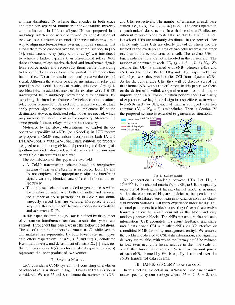
Let’s consider a CoMP system [14] consisting of a clusterof adjacent cells as shown in Fig. 1. Downlink transmission isconsidered. We use M and L to denote the numbers of eNBs
and UEs, respectively. The number of antennas at each basestation, i.e., eNBi (i = 1,2,⋯,M ) is NT . The eNBs operate ina synchronized slot structure. In each time slot, eNB allocatesdifferent resource block to its UEs, so that CCI within a cellis avoided. UEs are randomly distributed in the network. Forclarity, only three UEs are clearly plotted of which two arelocated in the overlapping area of two cells whereas the otherone lies in the central area of a cell. The unclear UEs inFig. 1 indicate those are not scheduled in the current slot. Thenumber of antennas at each UEj (j = 1,2,⋯, L) is NR. Weassume that UE1 is affiliated with eNB1 whereas eNB2 andeNB3 are the home BSs for UE2 and UE3, respectively. Forcell-edge users, they would suffer CCI from adjacent eNBs.As for the central area UEs, they will be directly served bytheir home eNBs without interference. In this paper, we focuson the design of downlink cooperative transmission aiming toimprove edge users’ communication performance. For clarityof exposition, we begin our design in a specific case in whichtwo eNBs and two UEs, each of them is equipped with twoantennas (NT = NR = 2), are included. Then in Section IVthe proposed scheme is extended to generalized situations.
(1)
(1)
1121
2xHp
(1)
(1)
1222
2xHp (1)
(1)11
111x
Hp
(2) (2)
12 12 1xH p
IN
Central areaEdge areaInterfering signalDesired signal
1UE
3eNB3UE
X2X2
X2
2UE
1eNB
2eNB
(1) (1) (1) (1)11 1 21 2x x+p p
11H (2) (2) (1) (1)12 1 22 2x x+p p
21H
12H22H
Modified MME
(1)(1)
2111
1x
Hp
(2)(2)
2212
1x
Hp
(1)(1)
2121
2xHp
(1) (1)
22 22 2xH p
IA
ZF
Fig. 1. System model.No cooperation is available between UEs. Let Hji ∈
CNR×NT be the channel matrix from eNBi to UEj . A spatiallyuncorrelated Rayleigh flat fading channel model is assumedso that the elements of Hji are modeled as independent andidentically distributed zero-mean unit-variance complex Gaus-sian random variables. All users experience block fading, i.e.,channel parameters in a block consisting of several successivetransmission cycles remain constant in the block and varyrandomly between blocks. The eNBs can acquire channel stateinformation (CSI) accurately via users’ feedback, and shareusers’ data or/and CSI with other eNBs via X2 interface ora modified MME (Mobility management entity). We assumethe backhaul dedicated to CSI, data information, and signalingdelivery are reliable, with which the latency could be reducedto low, even negligible levels relative to the time scale onwhich the channel state varies [15-16]. The transmit powerof each eNB, denoted by PT , is equally distributed over theeNB’s transmitted data streams.
III. IAN-BASED COMP TRANSMISSION
In this section, we detail an IAN-based CoMP mechanismunder specific system settings where M = 2, L = 2, and

NT = NR = 2, with which 3 data streams can be simul-taneously supported. We assume that UE1 is assigned to 2streams, denoted by x(1)1 and x(2)1 , respectively, while UE2 isserved with a single data stream x
(1)2 . Due to the symmetrical
feature of the system model, if UE1 is served by one streamand UE2 by two, the proposed scheme is directly applicable.Although the method based on interference alignment andcancellation (IAC) [17] can also achieve the same number ofconcurrent data streams with an identical system configuration,it requires receiver-side collaboration which is impractical todownlink communications. Moreover, the proposed IAN-basedstrategy only needs partial users’ data sharing between eNBs.Specifically, eNB1 transfers an arbitrary data stream to be sentto UE1, say x(2)1 to eNB2, whereas for the data intended forUE2, i.e., x(1)2 , it is shared between eNB2 and eNB1, thenboth eNBs transmit x(1)2 to UE2 cooperatively. According tothe above description, each eNB precodes and transmits twodata streams to two UEs, as shown in Fig. 1. On one hand,IN is used to adjust two interfering signals of the same datain opposite directions in a subspace such that they can beneutralized at a target UE. On the other hand, IA is appliedto align interference signals carrying different information inthe same direction in a subspace to reduce the received signaldimension. Based on the cooperative preprocessing at eNBs,ZF is employed at each UE to cancel the residual interferenceand recover the desired data.
A. IAN-Based Transmit Precoding Design
The mixed signal received at UE1 and UE2 can be ex-pressed, respectively, as Eqs. (1) and (2) below:
y1 =H11p(1)11 x
(1)1 +H12p
(2)12 x
(2)1 + (H11p
(1)21 +H12p
(1)22 )x
(1)2
+ z1(1)
y2 = (H21p(1)21 +H22p
(1)22 )x
(1)2 +H21p
(1)11 x
(1)1 +H22p
(2)12 x
(2)1
+ z2(2)
where Hji ∈ C2×2 (i, j = 1,2). The transmit symbols to UE1
and UE2 are denoted by x(m)1 (m = 1,2) and x(1)2 , respectively.Here we use the terminologies data symbol and data stream tomean the same since the latter can be regarded as a continuousprocess of symbol transmission. Moreover, the analysis in thispaper is based on a discrete-time process where the time indexis omitted for simplicity. p(m)ji ∈ CNT×1 is the precoding vectorthat eNBi adopts for data x(m)j to transmit to UEj .
The first two terms on the right hand side (RHS) of Eq. (1)indicate the expected signal for UE1, whereas the third termdenotes the interference caused by the transmission of shareddata x(1)2 from two collaborating eNBs to UE2. The first termon the RHS of Eq. (2) represents the expected transmissionto UE2, whereas the second and third terms denote theinterference caused by the transmission of x(1)1 from eNB1
to UE1 and x(2)1 from eNB2 to UE1, respectively. zj ∈ CNR×1
is an additive white Gaussian noise (AWGN) vector whoseelements have zero-mean and variance σ2
n. E(zjzHj ) = σ2
nINR,
where INRis an NR × NR identity matrix. Based on the
above description, both eNBs send x(1)2 to UE2, i.e., x(1)2 is
shared by two eNBs. As for UE1, its intended data x(1)1 andx(2)1 are precoded and transmitted by two eNBs, respectively,
i.e., one data is transferred from eNB1 to eNB2. Therefore,E(∥x
(m)1 ∥2) = PT /2 (m = 1,2), E(∥x
(1)2 ∥2) = PT /2.
From Eq. (1), one can see that two interfering signalscarry same data x(1)2 , so that joint precoding can be designedto achieve IN at UE1. As for (2), there are two differentinterferences carrying x
(1)1 and x
(2)1 , respectively. Hence, IA
is employed to align the interferences in one direction atUE2. Then, UE2 can implement ZF to cancel the alignedinterference and recover its expected information (see SectionIII.B for details). It should be noted that the direction in whichtwo interferences align at UE2 may be optimized to enhancetransmission performance. Due to limited space, we onlyinvestigate the alignment based on the subspace determinedby H21p
(1)11 or H22p
(2)12 .
The precoding vectors designed for eNB should thereforemeet the following conditions:
H11p(1)21 +H12p
(1)22 = 0, H21p
(1)11 =H22p
(2)12 (3)
We can then obtain:
p(1)22 = −H−1
12H11p(1)21 , p
(2)12 =H−1
22H21p(1)11 (4)
The second equation in Eq. (4) is to design p(2)12 such
that H22p(2)12 aligns in the direction determined by H21p
(1)11 .
Similarly, we can also design p(1)11 = H−1
21H22p(2)12 so as to
make H21p(1)11 align in the subspace determined by H22p
(2)12 .
For a concise analysis, we introduce equivalent matrices G1 =
H−122H21 and G2 =H−1
12H11. Then a general form of precoder,p(m)j2 = (−1)mGjp
(1)j1 where (m,j) ∈ {(1,2), (2,1)}, is ob-
tained. Note that when antenna configurations are generalized(see Section IV.A for detail), the inverse of channel matrixshould be replaced by Moore-Penrose pseudo-inverse so as tocalculate the precoders.
From the above general expression we can see that in orderto calculate p
(m)j2 , p(1)j1 should be determined first. Applying
the singular value decomposition (SVD) to Hj1 (j = 1,2),we get Hj1 = Uj1Dj1V
Hj1 where Uj1 = [u
(1)j1 u
(2)j1 ],
Dj1 =
⎡⎢⎢⎢⎢⎣
λ(1)j1 0
0 λ(2)j1
⎤⎥⎥⎥⎥⎦
and Vj1 = [v(1)j1 v
(2)j1 ]. The column
vectors of Uj1 and Vj1 indicate spatial features, whereas non-zero principal diagonal elements of Dj1, sorted in descendingorder, represent for the amplitude gains of a set of decoupledparallel subchannels. In order to achieve as high a transmissionrate as possible, we adopt p
(1)j1 = v
(1)j1 , i.e., the principal
subchannel with the maximum singular value λ(1)j1 is selected.Then, Eqs. (1) and (2) can be rewritten as (5) and (6) below:
y1 = λ(1)11 u
(1)11 x
(1)1 +H12G1v
(1)11 x
(2)1 + z1 (5)
y2 = (λ(1)21 u
(1)21 −H22G2v
(1)21 )x
(1)2 +H21v
(1)11 (x
(1)1 + x
(2)1 )
+ z2(6)

Here we should note that although p(1)j1 is a unit vector, p(1)j2
is probably not. Moreover, in order to achieve IN, the twosignals should have the same strength and be with oppositedirection; whereas for IA, only identical direction is required.As a consequence, p(2)12 should be normalized before using sothat neither power gain nor attenuation is introduced. However,p(1)22 cannot be scaled due to the purpose of IN. In practice, we
could adjust the signal with a higher channel gain to neutralizethe one with lower gain so as to avoid additional power cost.
From Eq. (5) one can see that the interferences causedby the transmission of x(1)2 from eNB1 and eNB2 to UE2
are neutralized at UE1 via IN. Eq. (6) indicates that theinterferences caused by sending x(1)1 and x(2)1 from two eNBsto UE1 align in the same direction at UE2 with IA. However,the interference is not eliminated, as shown in (6). Next, weelaborate the design of receive filter to cancel the residualinterference and recover the expected information.
B. Design of Receive Filter
In this subsection, ZF is employed to cancel the residualinterference and decode the expected data. Note that no user-side collaboration is assumed, so each UE implements post-processing independently.
Adopt FHj = [f
(1)j f
(2)j ]H to denote the filter matrix of
yj where j = 1,2. For simplicity, let C(1)1 = λ
(1)11 u
(1)11 =
∥C(1)1 ∥u
C(1)1
, C(2)1 = H12G1v
(1)11 = ∥C
(2)1 ∥u
C(2)1
, C(1)2 =
λ(1)21 u
(1)21 −H22G2v
(1)21 = ∥C
(1)2 ∥u
C(1)2
and C(2)2 = H21v
(1)11 =
∥C(2)2 ∥u
C(2)2
. The amplitude of C(m)j is ∥C
(m)j ∥ whereas
uC(m)j
=C(m)j /∥C
(m)j ∥ indicates the direction of C(m)j . These
coefficients are substituted into (5) and (6) and FHj is adopted
as the filter to obtain Eqs. (7) and (8).
y1 = FH1 ∥C
(1)1 ∥u
C(1)1
x(1)1 +FH
1 ∥C(2)1 ∥u
C(2)1
x(2)1 +FH
1 z1 (7)
y2 =FH2 ∥C
(1)2 ∥u
C(1)2
x(1)2 +FH
2 ∥C(2)2 ∥u
C(2)2
(x(1)1 + x
(2)1 )
+FH2 z2
(8)
Note that C(2)2 is essentially the coefficient of interferencepart of the mixed signal received by UE2. The design ofreceive filter should meet the following condition:
(f(m)j )
HuC(m′)j
= {α(m)j , m =m′
0 , m ≠m′(9)
where m,m′, j = 1,2 and 1 ≥ ∥α(m)j ∥ > 0. Then, the receive
filter for UEj is calculated as:
f(m)j =
uC(m)j
− uH
C(m′)j
uC(m)j
uC(m′)j
∥uC(m)j
− uH
C(m′)j
uC(m)j
uC(m′)j
∥
, m =m′ (10)
Substituting (10) into (7) and (8), we get (11) and (12).According to (11), the desired data x
(1)1 and x
(2)1 of UE1
can be decoded, respectively, in two mutually orthogonalsubspaces. As for (12), the expected data x
(1)2 of UE2 is
recovered in the subspace orthogonal to the one in whichresidual interference, indicated by the second term on the RHSof (12), is located.
C. Achievable Spectral-Efficiency Analysis
By observing the noise parts in (11) and (12), although co-channel interference is eliminated and the expected data isdecoded in an interference-free subspace, Fj is not a unitarymatrix, i.e., ⟨f (1)j , f
(2)j ⟩ ≠ 0. As a result, the noise power after
receive filtering becomes:
E {(FHj zj)(F
Hj zj)
H} = E {FHj zjz
Hj Fj} = σ
2nAj (13)
where Aj =
⎡⎢⎢⎢⎢⎣
1 (f(1)j )Hf
(2)j
(f(2)j )Hf
(1)j 1
⎤⎥⎥⎥⎥⎦
.
Given E(∥x(m)1 ∥2) = PT /2 where m = 1,2 and
E(∥x(1)2 ∥2) = PT /2, The achievable spectral efficiency for
each UE is computed as Eqs. (14) and (15). The effect of Aj
on R1 and R2 has been studied in [18]. For space limitationswe do not discuss it in this paper.
IV. GENERALIZATION OF IAN-COMP
In this section, we extend IAN-CoMP to general cases whilevarying antenna configurations at both the Tx and Rx sides, thenumbers of eNBs participating in CoMP and simultaneously
y1 = ∥C(1)1 ∥
⎡⎢⎢⎢⎣
(f(1)1 )Hu
C(1)1
0
⎤⎥⎥⎥⎦x(1)1 + ∥C
(2)1 ∥
⎡⎢⎢⎢⎣
0
(f(2)1 )Hu
C(2)1
⎤⎥⎥⎥⎦x(2)1 +FH
1 z1 (11)
y2 = ∥C(1)2 ∥
⎡⎢⎢⎢⎣
(f(1)2 )Hu
C(1)2
0
⎤⎥⎥⎥⎦x(1)2 + ∥C
(2)2 ∥
⎡⎢⎢⎢⎣
0
(f(2)2 )Hu
C(2)2
⎤⎥⎥⎥⎦(x(1)1 + x
(2)1 ) +FH
2 z2 (12)
R1 =2
∑m=1
R(m)1 =
2
∑m=1
log2
⎧⎪⎪⎪⎪⎨⎪⎪⎪⎪⎩
det
⎡⎢⎢⎢⎢⎢⎢⎣
INR+PT (FH
1 C(m)1 ) (FH
1 C(m)1 )
H
2σ2nA1
⎤⎥⎥⎥⎥⎥⎥⎦
⎫⎪⎪⎪⎪⎬⎪⎪⎪⎪⎭
(14)
R2 = log2
⎧⎪⎪⎪⎪⎨⎪⎪⎪⎪⎩
det
⎡⎢⎢⎢⎢⎢⎢⎣
INR+PT (FH
2 C(1)2 ) (FH
2 C(1)2 )
H
2σ2nA2
⎤⎥⎥⎥⎥⎥⎥⎦
⎫⎪⎪⎪⎪⎬⎪⎪⎪⎪⎭
(15)
served UEs. Before delving into details, we first provide onetheorem and three corollaries on IA and IN.
Theorem 1: Each of the signals generated to achieve inter-ference alignment or neutralization at an unintended receiverwhile being decoded at their intended receiver should beoriginated from a different transmitter.
Proof sketch: Take the transmission of x(1)1 and x(2)1 as
an example, as shown in Fig. 1. If both are sent from eNBi
and aligned in one direction at their unintended receiver UE2,where i ∈ {1,⋯,M} is the index of eNB, then H2ip
(1)2i =
H2ip(2)2i . One can easily see that these two signals also overlap
with each other at their intended receiver UE1, thus becomingindistinguishable. As for IN, if the signal carrying x
(1)1 is
neutralized at UE2, then H2ip(1)2i x
(1)1 = −H2ip
′(1)2i x
(1)1 , where
p′(1)2i represents the precoder for a duplicate signal to mitigate
the original interference H2ip(1)2i x
(1)1 at UE2. Then, the two
signals will also be neutralized at any other UEj where userindex j ∈ {1,⋯, L} and j ≠ 2. ∎
Corollary 1: If κ > 1 interferences are from an identicaltransmitter, they should be mapped into a κ-dimensional spaceat their unintended receivers so as to be distinguishable at theirintended receiver(s).
Proof sketch: According to Theorem 1, if Corollary 1 isnot satisfied, at least two signal components will overlap witheach other at a UE, thus becoming indistinguishable. Thus,Corollary 1 follows. ∎
Corollary 2: The same set of signals cannot be simultane-ously aligned with each other at more than one receiver.
Proof sketch: Take the transmission of x(1)1 and x(2)1 as anexample. According to Theorem 1, they should be sent by twoeNBs, say eNB1 and eNB2, separately, so as to be aligned inone direction at a UE. Without loss of generality, if two signalscarrying x(1)1 and x(2)1 are aligned with each other at UE1 andUE2, then H1ip
(1)1i =H1i′p
(2)1i′ and H2ip
(1)1i =H2i′p
(2)1i′ where
i, i′ ∈ {1,2} and i ≠ i′, should be satisfied simultaneously. Dueto the randomness of channel conditions, given p
(1)1i (or p(2)1i′ ),
a solution for the other precoder p(2)1i′ (or p(1)1i ), satisfying bothequations, usually does not exist. ∎
Similar to Corollary 2, we can derive the following corol-lary.
Corollary 3: The same pair of signals cannot be neutralizedat more than one receiver simultaneously.
Proof sketch: The proof is similar to that in Corollary 2. ∎In what follows, we extend the proposed IAN-CoMP to
more general cases.
A. Generalized Antenna Configurations
The proposed IAN-CoMP can be extended to the general sit-uation in which the antenna configurations at both transmitter
and receiver sides are variable. Since mobile stations/devicesare subject to severer restrictions such as cost and hardwarethan a base station, we assume NT ≥ NR. For clarity, ourdiscussion is confined to 2-eNB 2-UE system settings.
Let s1 = [x(1)1 ⋯ x
(NR)
1 ]T and s2 = [x(1)2 ⋯ x
(NR−1)2 ]T
denote the desired data of UE1 and UE2, respectively. Vectorss11 = [x
(1)1 ⋯ x
(NR−1)1 ]T and s2 are sent by eNB1, whereas
s12 = [x(1)1 ⋯ x
(NR−2)1 x
(NR)
1 ]T and s2 are sent by eNB2. Inother words, UE1’s data, except x(NR−1)
1 and x(NR)
1 , is sharedover both eNBs. eNB1 transfers x
(NR)
1 to eNB2 whereasx(NR−1)1 is sent by eNB1 exclusively. In addition, both eNBs
transmit s2 to UE2 cooperatively. In the above description,x(NR−1)1 and x(NR)
1 are taken as an example in the mechanismdesign. In practice, any two arbitrary data streams, say x
(m)1
and x(n)1 (m ≠ n), can be used. Our scheme is still applicablein such cases. For simplicity, an equal power allocation isadopted, i.e., E(∥x
(m)1 ∥2) = E(∥x
(n)2 ∥2) = PT /(2NR − 2)
where m = 1,⋯,NR and n = 1,⋯,NR − 1.Given the above system configurations, the received mixed
signal at UE1 and UE2 can be expressed as (16) and (17),where Hji ∈ CNR×NT (i, j = 1,2). p
(m)1i ∈ CNT×1 (m =
1,⋯,NR) is the precoding vector for data x(m)1 that eNBi
transmits to UE1. P(s2)i ∈ CNT×(NR−1) represents the precod-ing matrix for s2 that eNBi transmits to UE2. The first threeterms on the RHS of (16) indicate the desired signal for UE1,whereas the fourth term denotes the interference caused by thetransmission of shared data s2 from two cooperating eNBs toUE2. In (17), the first term on the RHS represents the expectedtransmission to UE2, whereas the next three terms denote theinterference caused by the transmission of s11 from eNB1 toUE1 and s12 from eNB2 to UE1, respectively. In (16), twointerference signals carry the same data s2, and hence jointprecoding can be adopted to achieve IN at UE1. In (17), IA isemployed to align the interferences in one direction so that themixed signal’s dimension is reduced at UE2. The precodingvectors designed for eNB should thus meet the followingconditions:
{H11P
(s2)1 +H12P
(s2)2 = 0
H21p(m)11 +H22p
(m)12 =H21p
(NR−1)11 =H22p
(NR)
12 .(18)
According to Theorem 1, in the second equation of (18),since H21p
(NR−1)11 =H22p
(NR)
12 holds, the solutions for p(m)11
and p(m)12 w.r.t. H21p
(m)11 = H21p
(NR−1)11 and H22p
(m)12 =
H22p(NR)
12 alone are not available. In order to solve thisproblem, we let both eNBs transmit x(m)1 (m = 1,⋯,NR − 2)and align the combined signal H21p
(m)11 +H22p
(m)12 with either
H21p(NR−1)11 or H22p
(NR)
12 , so that all interferences at UE2 arealigned in one direction.
y1 =NR−2
∑m=1
(H11p(m)11 +H12p
(m)12 )x
(m)1 +H11p
(NR−1)11 x
(NR−1)1 +H12p
(NR)
12 x(NR)
1 + (H11P(s2)1 +H12P
(s2)2 ) s2 + z1 (16)
y2 = (H21P(s2)1 +H22P
(s2)2 ) s2 +
NR−2
∑m=1
(H21p(m)11 +H22p
(m)12 )x
(m)1 +H21p
(NR−1)11 x
(NR−1)1 +H22p
(NR)
12 x(NR)
1 + z2 (17)
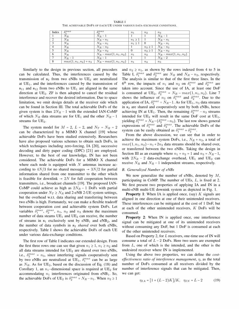
TABLE ITHE ACHIEVABLE DOFS OF EACH UE UNDER VARIOUS DATA-EXCHANGE CONDITIONS.
Index δmax1 δmax
2 n1 n2 n3
1 NR NR − 1 1 1 NR − 12 NR NR − n1 n1 ≥ 1 1 NR − n1
3 NR NR − n1 n1 ≥ 1 0 NR − n1
4 NR NR − n2 1 n2 ≥ 1 NR − n2
5 NR NR − n2 0 n2 ≥ 1 NR − n2
6 NR NR −max(1, n1, n2) n1 n2 NR −max(1, n1, n2)7 NR − 1 NR − 1 1 1 NR − 28 max(1, n1, n2) + n3 NR −max(1, n1, n2) n1 n2 n3
Similarly to the design in previous section, all precoderscan be calculated. Thus, the interferences caused by thetransmission of s2 from two eNBs to UE2 are neutralizedat UE1, and the interferences caused by the transmission ofs11 and s12 from two eNBs to UE1 are aligned in the samedirection at UE2. ZF is then adopted to cancel the residualinterference and recover the desired information. Due to spacelimitation, we omit design details at the receiver side whichcan be found in Section III. The total achievable DoFs of thegiven system is thus 2NR − 1 with the extended IAN-CoMPof which NR data streams are for UE1 and the other NR − 1streams for UE2.
The system model for M = 2, L = 2, and NT = NR = 2can be characterized by a MIMO X channel [19] whoseachievable DoFs have been studied extensively. Researchershave also proposed various schemes to obtain such DoFs, inwhich techniques including zero-forcing, IA [20], successivedecoding and dirty paper coding (DPC) [21] are employed.However, to the best of our knowledge, IN has not beenconsidered. The achievable DoFs for a MIMO X channelwhere each node is equipped with N antennas increase ac-cording to 4N/3 for no shared messages → 3N/2 for partialinformation shared from one transmitter to the other whichis feasible for downlink → 2N for full cooperation betweentransmitters, i.e., broadcast channels [19]. The proposed IAN-CoMP could achieve as high as 2NR − 1 DoFs with partialcooperation under NT ≥ NR and 2-eNB 2-UE system settings,but the overhead w.r.t. data sharing and transferring betweentwo eNBs is high. Fortunately, we can make a flexible tradeoffbetween cooperation cost and achievable system DoFs. Letvariables δmax
1 , δmax2 , n1, n2 and n3 denote the maximum
number of data steams UE1 and UE2 can receive, the numberof streams in s1 exclusively sent by eNB1 and eNB2, andthe number of data symbols in s2 shared over both eNBs,respectively. Table I shows the achievable DoFs of each UEunder various data-exchange conditions.
The first row of Table I indicates our extended design. Fromthe first three rows one can see that given n1 ≥ 1, n1 ≥ n2 andall data streams intended for UE2 are shared over two eNBs,i.e., δmax
2 = n3, since interfering signals cooperatively sentby two eNBs are neutralized at UE1, δmax
1 can be as largeas NR. As for UE2, based on the discussion of Eq. (18) andCorollary 1, an n1−dimensional space is required at UE2 foraccommodating n1 interferences originated from eNB1. So,the achievable DoFs of UE2 is δmax
2 = NR −n1. When n2 ≥ 1
and n2 ≥ n1, as shown by the rows indexed from 4 to 5 inTable I, δmax
1 and δmax2 are NR and NR − n2, respectively.
The analysis is similar to that of the first three lines. In the6th row, the impacts of n1 and n2 on δmax
1 and δmax2 are
taken into account. Since the use of IA, at least one DoFis consumed at UE2, δmax
2 = NR − max(1, n1, n2). Line 7shows the influence of n3 on δmax
1 and δmax2 . Due to the
application of IA, δmax2 = NR−1. As for UE1, n3 data streams
in s2 are shared and cooperatively sent by both eNBs, henceachieving IN at UE1. Then, the remaining δmax
2 − n3 streamsintended for UE2 will result in the same DoF cost at UE1,yielding δmax
1 = NR−(δmax2 −n3). The last row shows general
expressions of δmax1 and δmax
2 . The achievable DoFs of thesystem can be easily obtained as δmax
1 + δmax2 .
From the above discussion, we can see that in order toachieve the maximum system DoFs, i.e., NR + n3, a total ofmax(1, n1, n2)−n1+2n3 data streams should be shared over,or transferred between the two eNBs. Taking the design inSection III as an example where n1 = n2 = 1 and n3 = NR−1,with 2NR − 2 data-exchange overhead, UE1 and UE2 canreceive NR and NR − 1 independent streams, respectively.
B. Generalized Number of eNBs
We now generalize the number of eNBs, denoted by M ,participating in CoMP. The number of UEs, L, is fixed at 2.We first present two properties of applying IA and IN in amulti-eNB multi-UE downink system as depicted in Fig. 1.
Property 1: When IA is applied once, (say) K signals arealigned in one direction at one of their unintended receivers.These interferences can be mitigated at the cost of 1 DoF, butat each of the other unintended receivers, K DoFs will beconsumed.
Property 2: When IN is applied once, one interferencesignal can be mitigated at one of its unintended receiverswithout consuming any DoF, but 1 DoF is consumed at eachof the other unintended receivers.
Based on Property 2, for L receivers, one-time use of IN willconsume a total of L − 2 DoFs. Here two users are exemptedfrom L, one of which is the intended, and the other is theundesired receiver where IN is implemented.
Using the above two properties, we can define the cost-effectiveness ratio of interference management, η, as the totalnumber of DoFs consumed at all receivers divided by thenumber of interference signals that can be mitigated. Then,we can get:
ηIA = [1 + (L − 2)K]/K, ηIN = L − 2 (19)
2UE
11H1eNB 2eNB 3eNB
1UE
12H 22H 23H21H 13H
(1)(1)
21
1
ii x
Hp
(2)(2)
2 ' 1 '1
ii x
Hp
IA
ZF
(3)(3)
2 '' 1 ''1
ii x
Hp
(1) (1)2 ' 2 ' 2i i xH p
(1) (1)
22
2i
ix
H p(2)(2)
22
2
ii x
Hp
(2)(2)
2'
2'
2
ii x
Hp
Interfering signalDesired signal
(1)
(1)
1'
2'
2i
ix
Hp
(1)
(1)
12
2i
ix
Hp
(2)(2)
1 ' 1 '1
ii x
Hp
(1) (1)
1 1 1i i xH p
IN
(2) (2)
1 ' 2 ' 2
iix
H p
(2) (2)
12
2i
ix
H p
(3)(3)
1''
1''
1i
i xH
p
Fig. 2. IAN-CoMP extension under 3-eNB and 2-UE system settings.
3UE
11H 1eNB 2eNB
2UE
21H 32H22H
1UE
12H 31H
(1)(1)
33
3i
i xHp
(1)(1)
3'
3'
3i
i xHp
(1)(1)
31
1
ii x
Hp
(2) (2)3 ' 1 ' 1i i xH p
(1)(1)
21
1
ii x
Hp
(2)(2)
2 ' 1 '1
ii x
Hp
IA
(1) (1)
2 ' 2 ' 2i i xH p
(1) (1)
2 2 2i i xH p
(1)
(1)
23
3i
ix
Hp
(1)
(1)
2'
3'
3i
ix
Hp
(1) (1)
3 ' 2 ' 2i
ix
H p
(1) (1)
32
2i
ix
H p
Interfering signalDesired signal
IN
(1)(1)
1 '3 '
3
iix
Hp
(1)(1)
13
3
iix
Hp
(1)
(1)
1'
2'
2i
ix
Hp
(1)
(1)
12
2i
ix
Hp
(2) (2)1 ' 1 ' 1i
i xH p
(1) (1)
1 11
i ix
H p
Fig. 3. IAN-CoMP extension under 2-eNB and 3-UE system settings.
where K is the number of aligned signals. Note that L shouldbe at least 2 for multi-user CoMP transmission. When L = 2,K interferences could be mitigated at the expense of 1 DoF, soηIA = 1/K. As for IN, one interference could be eliminatedat no cost of DoFs, thus ηIN = 0. Eq. (19) shows that asL grows larger than 2, both ηIA and ηIN are greater than 1and increase accordingly, i.e., more DoFs are consumed forinterference mitigation.
In practice, IA and IN can be implemented in a centralizedway, i.e., all signal components are aligned in one directionor paired and neutralized at a single UE; or in a distributedmanner, i.e., alignment and neutralization of various subsets ofinterferences are done at multiple UEs. However, we can showthat given the same set of interferences, DoF costs of bothcentralized IA/IN and distributed IA/IN are the same. Due tospace limitation, we omit details. Without loss of generality, acentralized implementation is used in the following extensionof IAN-CoMP.
Suppose M > 2, L = 2 and NR ≥M , i.e., UE has sufficientantennas to decode its information. Similarly to the processingshown in Fig. 1, IN is implemented at UE1 while IA isachieved at UE2. The difference between M = 2 (SectionIII) and M > 2 lies in the fact that when M = 2, there areonly two signal components of s1 which are sent by eNB1
and eNB2, respectively; for the other signals intended to UE1,they are cooperatively sent by both eNBs so as to achievealignment at UE2. In case of M > 2, at most M signals couldbe explicitly sent by the eNBs whereas for the remainders,cooperative transmissions could be done by C2
M combinationsof eNB-pairs. Since signals intended for UE2, i.e., s2, areneutralized at UE1, we have δmax
1 = NR. As for UE2, usingIA consumes 1 DoF, hence δmax
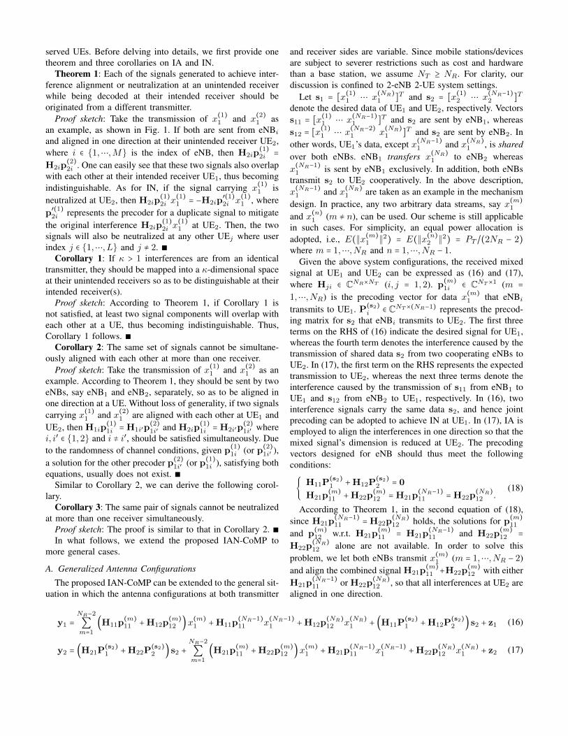
2 = NR − 1. So, when M > 2eNBs participate in CoMP, we can achieve a selection diversitygain from multiple eNBs while keeping the total system DoFsintact. Taking system settings M = 3, L = 2, NR = 3, andNT ≥ NR as an example, the proposed IAN-CoMP can beimplemented as shown in Fig. 2. The extension of IAN-CoMPto more general M can be readily achieved.
In Fig. 2, the subscripts i, i′ and i′′ indicate the indices ofeNBs, and i ≠ i′ ≠ i′′. As can be seen in this instance, x(1)1 ,x(2)1 and x(3)1 are sent by three eNBs, respectively, so that IA
is achieved at UE2. Moreover, x(1)2 and x(2)2 are sent from twoarbitrarily selected eNB-pairs, and two corresponding signal-pairs achieve IN at UE1 separately. As a result, we support a
total of five concurrent streams, three of which are intendedfor UE1 and two for UE2.
C. Generalized Number of UEs
Here we generalize the number of simultaneously servedUEs, L > 2. For simplicity of presentation, the number ofeNBs, M is fixed at 2, and NR ≥M .
We assume IN is implemented at UE1, and IA is achievedat UE2. According to Corollaries 2 and 3, signals achieving INor IA at one UE cannot establish the same relationship at theother UEs. Also, based on Eq. (18), signals intended to UE1
can be explicitly or cooperatively sent by the two eNBs so as toachieve IA at UE2. In addition, since more CCI is introducedas L increases, the achievable DoFs of a user are dependenton those of the others. So, we get δmax
1 = NR − (L − 1),δmax2 = NR−1−∑
Ll=3 δ
maxl and δmax
j = NR−∑Ll=1,l≠j δ
maxl (j =
3,⋯, L) where l and j are the indices of UEs. By observingthe expression of δmax
j (j ≥ 3) and observing that δmaxj ≥ 1
(j = 1,⋯, L), we have:
⎧⎪⎪⎪⎪⎪⎪⎨⎪⎪⎪⎪⎪⎪⎩
∑Ll=1 δ
maxl = NR
∑Ll=3 δ
maxl ≤ NR − 2
∑Ll=1,l≠j δ
maxl ≤ NR − 1, j = 3,⋯, L
δmaxj > 0, j = 1,⋯, L.
(20)
From the first equation in (20) we can see that when L > 2,the achievable system DoFs are NR. Moreover, since δmax
1 ≥
1, we get L ≤ NR. Therefore, at most L = NR users can besimultaneously supported, each being served by a single datastream.
Taking the system settings M = 2, L = 3, NR = 4,and NT ≥ NR as an example, (δmax
1 , δmax2 , δmax
3 ) can beselected from the set {(2,1,1), (1,2,1), (1,1,2)} so that4 independent data streams can be simultaneously supported.So, there could be various ways to allocate DoFs to multipleusers. In practice, round-robin [22], weighted fair scheduling[23], and other channel allocation algorithms can be employedfor DoFs distribution. Due to space limitation, we do notelaborate them in this paper. Fig. 3 shows the extension ofIAN-CoMP under (δmax
1 , δmax2 , δmax
3 ) = (2,1,1). As can beseen, x(1)1 and x(2)1 are explicitly sent, whereas x(1)2 and x(1)3
are cooperatively sent by the two eNBs, so that IA and INare achieved at UE2 and UE1, respectively. Given the other(δmax
1 , δmax2 , δmax
3 ) values, the proposed IAN-CoMP can besimilarly implemented.
V. EVALUATION
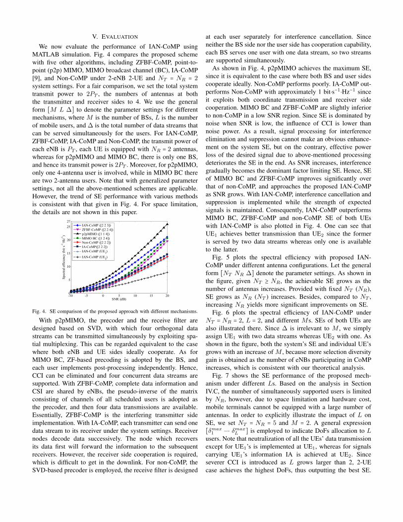
We now evaluate the performance of IAN-CoMP usingMATLAB simulation. Fig. 4 compares the proposed schemewith five other algorithms, including ZFBF-CoMP, point-to-point (p2p) MIMO, MIMO broadcast channel (BC), IA-CoMP[9], and Non-CoMP under 2-eNB 2-UE and NT = NR = 2system settings. For a fair comparison, we set the total systemtransmit power to 2PT , the numbers of antennas at boththe transmitter and receiver sides to 4. We use the generalform [M L ∆] to denote the parameter settings for differentmechanisms, where M is the number of BSs, L is the numberof mobile users, and ∆ is the total number of data streams thatcan be served simultaneously for the users. For IAN-CoMP,ZFBF-CoMP, IA-CoMP and Non-CoMP, the transmit power ofeach eNB is PT , each UE is equipped with NR = 2 antennas,whereas for p2pMIMO and MIMO BC, there is only one BS,and hence its transmit power is 2PT . Moreover, for p2pMIMO,only one 4-antenna user is involved, while in MIMO BC thereare two 2-antenna users. Note that with generalized parametersettings, not all the above-mentioned schemes are applicable.However, the trend of SE performance with various methodsis consistent with that given in Fig. 4. For space limitation,the details are not shown in this paper.
-10 -5 0 5 10 15 200
5
10
15
20
2527
SNR (dB)
Spec
tral e
ffici
ency
(bit ⋅
s-1⋅ H
z-1)
IAN-CoMP ([2 2 3])ZFBF-CoMP ([2 2 4])p2pMIMO ([1 1 4])MIMO BC ([1 2 4])Non-CoMP ([2 2 2])IA-CoMP([2 2 2])IAN-CoMP (UE1)
IAN-CoMP (UE2)
Fig. 4. SE comparison of the proposed approach with different mechanisms.
With p2pMIMO, the precoder and the receive filter aredesigned based on SVD, with which four orthogonal datastreams can be transmitted simultaneously by exploiting spa-tial multiplexing. This can be regarded equivalent to the casewhere both eNB and UE sides ideally cooperate. As forMIMO BC, ZF-based precoding is adopted by the BS, andeach user implements post-processing independently. Hence,CCI can be eliminated and four concurrent data streams aresupported. With ZFBF-CoMP, complete data information andCSI are shared by eNBs, the pseudo-inverse of the matrixconsisting of channels of all scheduled users is adopted asthe precoder, and then four data transmissions are available.Essentially, ZFBF-CoMP is the interfering transmitter sideimplementation. With IA-CoMP, each transmitter can send onedata stream to its receiver under the system settings. Receivernodes decode data successively. The node which recoversits data first will forward the information to the subsequentreceivers. However, the receiver side cooperation is required,which is difficult to get in the downlink. For non-CoMP, theSVD-based precoder is employed, the receive filter is designed
at each user separately for interference cancellation. Sinceneither the BS side nor the user side has cooperation capability,each BS serves one user with one data stream, so two streamsare supported simultaneously.
As shown in Fig. 4, p2pMIMO achieves the maximum SE,since it is equivalent to the case where both BS and user sidescooperate ideally. Non-CoMP performs poorly. IA-CoMP out-performs Non-CoMP with approximately 1 bit⋅s−1⋅Hz−1 sinceit exploits both coordinate transmission and receiver sidecooperation. MIMO BC and ZFBF-CoMP are slightly inferiorto non-CoMP in a low SNR region. Since SE is dominated bynoise when SNR is low, the influence of CCI is lower thannoise power. As a result, signal processing for interferenceelimination and suppression cannot make an obvious enhance-ment on the system SE, but on the contrary, effective powerloss of the desired signal due to above-mentioned processingdeteriorates the SE in the end. As SNR increases, interferencegradually becomes the dominant factor limiting SE. Hence, SEof MIMO BC and ZFBF-CoMP improves significantly overthat of non-CoMP, and approaches the proposed IAN-CoMPas SNR grows. With IAN-CoMP, interference cancellation andsuppression is implemented while the strength of expectedsignals is maintained. Consequently, IAN-CoMP outperformsMIMO BC, ZFBF-CoMP and non-CoMP. SE of both UEswith IAN-CoMP is also plotted in Fig. 4. One can see thatUE1 achieves better transmission than UE2 since the formeris served by two data streams whereas only one is availableto the latter.
Fig. 5 plots the spectral efficiency with proposed IAN-CoMP under different antenna configurations. Let the generalform [NT NR ∆] denote the parameter settings. As shown inthe figure, given NT ≥ NR, the achievable SE grows as thenumber of antennas increases. Provided with fixed NT (NR),SE grows as NR (NT ) increases. Besides, compared to NT ,increasing NR yields more significant improvements on SE.
Fig. 6 plots the spectral efficiency of IAN-CoMP underNT = NR = 2, L = 2, and different Ms. SEs of both UEs arealso illustrated there. Since ∆ is irrelevant to M , we simplyassign UE1 with two data streams whereas UE2 with one. Asshown in the figure, both the system’s SE and individual UE’sgrows with an increase of M , because more selection diversitygain is obtained as the number of eNBs participating in CoMPincreases, which is consistent with our theoretical analysis.
Fig. 7 shows the SE performance of the proposed mech-anism under different Ls. Based on the analysis in SectionIV.C, the number of simultaneously supported users is limitedby NR, however, due to space limitation and hardware cost,mobile terminals cannot be equipped with a large number ofantennas. In order to explicitly illustrate the impact of L onSE, we set NT = NR = 5 and M = 2. A general expression[δmax
1 ⋯ δmaxL ] is employed to indicate DoFs allocation to L
users. Note that neutralization of all the UEs’ data transmissionexcept for UE1’s is implemented at UE1, whereas for signalscarrying UE1’s information IA is achieved at UE2. Sinceseverer CCI is introduced as L grows larger than 2, 2-UEcase achieves the highest DoFs, thus outputting the best SE.

-10 -5 0 5 10 15 200
5
10
15
20
25
30
35
40
45
50
SNR (dB)
Spec
tral e
fficie
ncy
(bit ⋅
s-1⋅ H
z-1)
IAN-CoMP([2 2 3])IAN-CoMP([4 2 3])IAN-CoMP([3 3 5])IAN-CoMP([4 3 5])IAN-CoMP([4 4 7])IAN-CoMP([6 4 7])
Fig. 5. SE of IAN-CoMP under different NT andNR.
2T RN N= = , 2L = , 2,3,4,5M = 。
-10 -5 0 5 10 15 200
5
10
15
20
25
SNR (dB)
Spe
ctra
l eff
icie
ncy
(bit
⋅ s-1
⋅ Hz-1
)
UE1
UE2
UE1+UE
2
2-eNB3-eNB4-eNB5-eNB
-10 -5 0 5 10 15 200
5
10
15
20
25
SNR (dB)
Spe
ctra
l eff
icie
ncy
(bit
⋅ s-1
⋅ Hz-1
)
UE1
UE2
UE1+UE
2
2-eNB3-eNB4-eNB5-eNB
Fig. 6. SE of IAN-CoMP under NT = NR = 2,L = 2, and different Ms.
-10 -5 0 5 10 15 200
10
20
30
40
50
60
SNR (dB)
Spec
tral e
ffici
ency
(bit ⋅
s-1
⋅ Hz-1
)
2-UE [5 4]3-UE [3 1 1]3-UE [1 3 1]4-UE [2 1 1 1]4-UE [1 2 1 1]5-UE [1 1 1 1 1]
18 18.5 19 19.5 2032
34
36
38
40
Fig. 7. SE of IAN-CoMP under NT = NR = 5,M = 2, and different Ls.
Given L > 2 and the same system DoFs, SE improves with anincrease of L since it benefits from multiple simultaneously-served users. Especially when SNR is low, such benefits mayoutweigh the performance loss due to severer CCI. So, the SEof 5-UE case slightly outperforms that with 2-UE under smallSNR. Note that IN yields less effective signal power loss ascompared to IA, resulting in higher SE, e.g., for the two 3-UEcases, the [1 3 1] DoF allocation excels the [3 1 1] case in SE,since 4 data transmissions achieve IN for the former whereasonly 2 for the latter.
VI. CONCLUSION
In this paper, a new CoMP mechanism based on IAN isproposed. By exploiting the BS-side cooperation, transmitprecoding and receive filtering are designed jointly. On onehand, IN is used to align two interfering signals carrying thesame data in opposite directions in a subspace such that theycan be canceled out. On the other hand, IA is applied toalign interference signals carrying different information in thesame direction in one subspace so as to reduce the dimensionof received signal. Based on the cooperative preprocessingat eNBs, ZF is employed at the receiver side to cancel theresidual interference and recover the desired information. Thisscheme is designed first under a specific system configuration,and then extended to more general cases. The proposed IAN-CoMP could achieve effective interference cancellation andsuppression by exploiting limited cooperation, hence improv-ing spectral efficiency for cell-edge users significantly.
ACKNOWLEDGMENT
This work was supported in part by NSFC (61173135, U1405255, 61231008, 61102057); the 111 Project (B08038). Itwas also supported in part by the US National ScienceFoundation under Grant 1160775.
REFERENCES
[1] G. Y. Li, Z. Xu, C. Xiong, et al., “Energy-efficient wireless communica-tions: Tutorial, survey, and open issues,” IEEE Wireless Commun. Mag.,vol. 18, no. 6, pp. 28-35, 2011.
[2] 3GPP TR36.814, “Further advancements for E-UTRA physical layeraspects; Coordinated multiple point transmission and reception,” 2010.
[3] P. Marsch, G. P. Fettweis, “Coordinated multi-point in mobile communi-cations: From theory to practice,” Cambridge Univ. Press, 2011.
[4] W. Liu, S. Han, C. Yang, “Hybrid cooperative transmission in heteroge-neous networks,” in Proc. of the IEEE Int. Sympo. on Personal Indoorand Mobile Radio Commun. (PIMRC), pp. 921-925, 2012.
[5] S. Han, C. Yang, M. Bengtsson, et al., “Channel norm-based userscheduler in coordinated multi-point systems,” in Proc. of the IEEEGlobal Commun. Conf. (GLOBECOM), pp. 1-5, 2009.
[6] Q. Zhang, C. Yang, “Semi-dynamic mode selection in base station coop-erative transmission system,” in Proc. of the IEEE Vehicular TechnologyConf. (VTC), pp. 1-5, 2011.
[7] C. M. Yetis, T. Gou, S. A. Jafar, et al., “On feasibility of interferencealignment in MIMO interference networks,” IEEE Trans. Sig. Process.,vol. 58, no. 9, pp. 4771-4782, 2010.
[8] C. Na, X. Hou, A. Harada, “Two-cell coordinated transmission schemebased on interference alignment and MU-MIMO beamforming,” in Proc.of the IEEE Vehicular Technology Conf. (VTC), pp. 1-5, 2012.
[9] S. M. Razavi, T. Ratnarajah, “Interference alignment in partially coordi-nated multipoint receivers,” in Proc. of the IEEE Int. Sympo. on PersonalIndoor and Mobile Radio Commun. (PIMRC), pp. 1114-1118, 2013.
[10] J. Chen, A. Singh, P. Elia, et al., “Interference neutralization forseparated multiuser uplink-downlink with distributed relays,” in Proc. ofthe Inf. Theory and Applications Workshop (ITA), pp. 1-9, 2011.
[11] T. Gou, S. A. Jafar, C. Wang, et al., “Aligned interference neutralizationand the degrees of freedom of the 2×2×2 interference channel,” IEEETrans. Inf. Theory, vol. 58, no. 7, pp. 4381-4395, 2012.
[12] N. Lee, C. Wang, “Aligned interference neutralization and the degrees offreedom of the two-user wireless networks with an instantaneous relay,”IEEE Trans. Commun., vol. 61, no. 9, pp. 3611-3619, 2013.
[13] Z. Ho, E. A. Jorswieck, “Instantaneous relaying: optimal strategies andinterference neutralization,” IEEE Trans. Sig. Process., vol. 60, no. 12,pp. 6655-6668, 2012.
[14] S. A. Jafar, S. Shamai, “Degrees of freedom region of the MIMO Xchannel,” IEEE Trans. Inf. Theory, vol. 54, no. 1, pp. 151-170, 2008.
[15] V. Jungnickel, K. Manolakis, S. Jaeckel, et al., “Backhaul requirementsfor inter-site cooperation in heterogeneous LTE-Advanced networks,” inProc. of the IEEE Int. Conf. on Commun. (ICC), pp. 905-910, 2013.
[16] I. F. Akyildiz, D. M. Gutierrez-Estevez, R. Balakrishnan, E. Chavarria-Reyes, “LTE-Advanced and the evolution to Beyond 4G (B4G) systems,”Physical Communication, vol. 10, pp. 31-60, 2014.
[17] S. Gollakota, S. D. Perli, D. Katabi, “Interference alignment andcancellation,” in Proc. of the ACM SIGCOMM Conf. on Data Commun.(SIGCOMM), pp. 159-170, 2009.
[18] Z. Li, B. Shen, J. Li, “Interference alignment and cancellation basedconcurrent transmission and scheduling scheme for multiuser CR-MIMOsystem,” China communications, vol. 10, no. 8, pp. 36-43, 2013.
[19] S. A. Jafar, S. Shamai, “Degrees of freedom region of the MIMO Xchannel,” IEEE Trans. Inf. Theory, vol. 54, no. 1, pp. 151-170, 2008.
[20] M. A. Maddah-Ali, A. S. Motahari, A. K. Khandani, “Communicationover MIMO X channels: interference alignment, decomposition, andperformance analysis,” IEEE Trans. Inf. Theory, vol. 54, no. 8, pp. 3457-3470, 2008.
[21] M. A. Maddah-Ali, A. S. Motahari, A. K. Khandani, “Signaling overMIMO multi-base systems: combination of multi-access and broadcastschemes,” in Proc. of the IEEE Int. Sympo. on Inf. Theory (ISIT), pp.2104-2108, 2006.
[22] C. Simon, G. Leus, “Round-robin scheduling for orthogonal beamform-ing with limited feedback ,” IEEE Trans. Wireless Commun., vol. 10, no.8, pp. 2486-2496, 2011.
[23] M. Mehrjoo, M. K. Awad, M. Dianati, Xuemin Shen, “Design of fairweights for heterogeneous traffic scheduling in multichannel wirelessnetworks,” IEEE Trans. Commun., vol. 58, no. 10, pp. 2892-2902, 2010.