Controls - parlonsaviation.com · ent. V00D11 029337 Pilots 27.2 Controls Description controls....
12
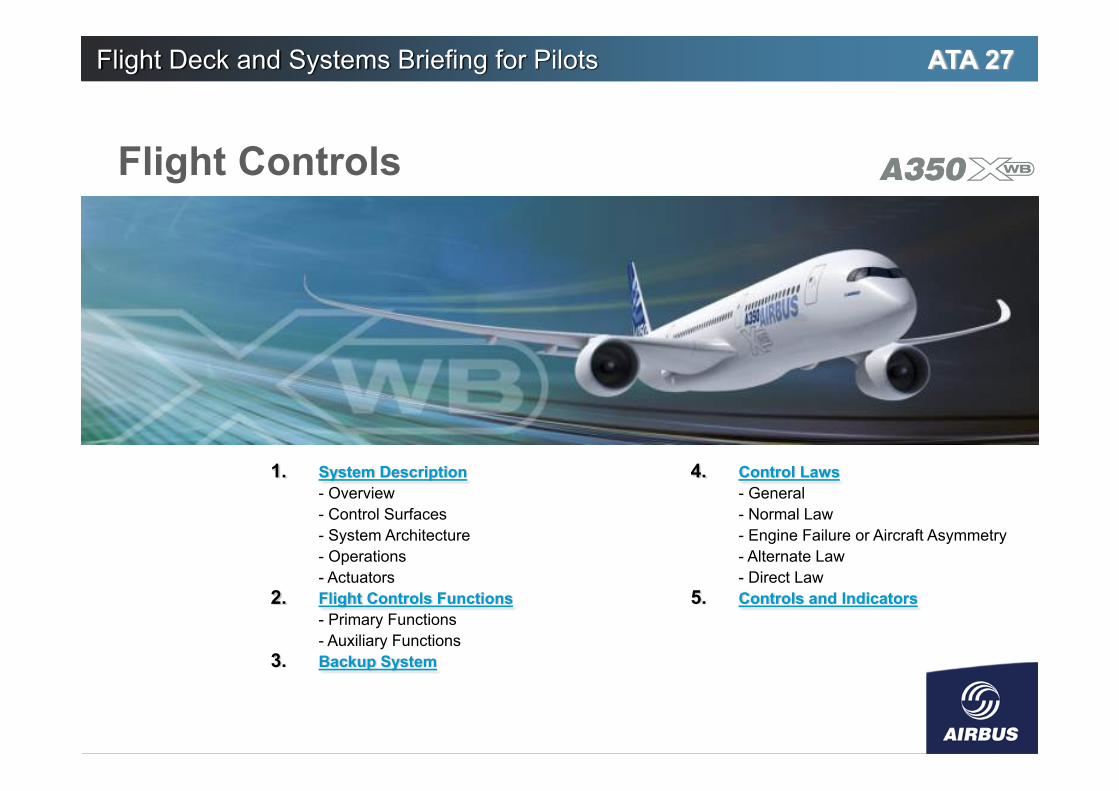
Flight Deck and Systems Briefing for Pilots 1. System Description - Overview - Control Surfaces - System Architecture - Operations - Actuators 2. Flight Controls Functions - Primary Functions - Auxiliary Functions 3. Backup System 4. Control Laws - General - Normal Law - Engine Failure or Aircraft Asymmetry - Alternate Law - Direct Law 5. Controls and Indicators ATA 27 Flight Controls
Transcript of Controls - parlonsaviation.com · ent. V00D11 029337 Pilots 27.2 Controls Description controls....
Flight Deck and Systems Briefing for Pilots
1. System Description- Overview- Control Surfaces- System Architecture- Operations- Actuators
2. Flight Controls Functions- Primary Functions- Auxiliary Functions
3. Backup System
4. Control Laws- General- Normal Law- Engine Failure or Aircraft Asymmetry- Alternate Law- Direct Law
5. Controls and Indicators
ATA 27
Flight Controls

© A
IRBU
S S.
A.S.
All
right
s re
serv
ed. C
onfid
entia
l and
pro
prie
tary
doc
umen
t.
27.2V00D11029337 Flight Deck and Systems Briefing for Pilots
A350 Flight Controls1.System Description
The A350 has fly-by-wire flight controls.The flight controls can be divided into two categories:• The primary flight controls which control the
aircraft according to the three axes (Roll, Pitch andYaw) and fulfill the auxiliary functions (speedbrakes,ground spoilers,…)
• The slats and flaps which fulfill the high-liftfunction.
The A350 flight controls system benefits from evolutionsintroduced on the A380:
• Integration of the Flight Guidance (FG) and FlightEnvelope (FE) functions in the Primary FlightComputers (PRIMs)
• Replacement of all mechanical backup controls byelectrical backup controls
• Addition of a new pitch trim switch which replacesthe trim wheels
• Introduction of active stability for longitudinal andlateral axes
• Introduction of Electro-Hydrostatic Actuators (EHAs)and Electro Backup Hydraulic Actuators (refer toActuators).
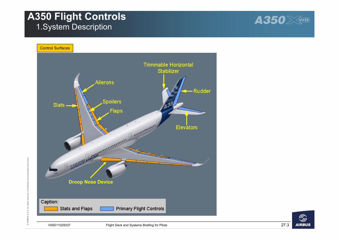
Overview Control SurfacesThe A350 has:• 4 ailerons• 14 spoilers• 2 elevators and 1 Trimmable Horizontal Stabilizer
(THS)• 1 rudder• 12 slats, 4 Adaptive Dropped Hinge Flaps and 2
Droop Nose Devices.
The A350 has two independent hydraulic circuits andtwo independent electrical circuits which power the flightcontrols surfaces. For more information refer to
Power supply for the Actuators and Control Surfaces
© A
IRBU
S S.
A.S.
All
right
s re
serv
ed. C
onfid
entia
l and
pro
prie
tary
doc
umen
t.
27.3V00D11029337 Flight Deck and Systems Briefing for Pilots
A350 Flight Controls1.System Description
Control Surfaces
Droop Nose Device
© A
IRBU
S S.
A.S.
All
right
s re
serv
ed. C
onfid
entia
l and
pro
prie
tary
doc
umen
t.
27.4V00D11029337 Flight Deck and Systems Briefing for Pilots
A350 Flight Controls1.System Description
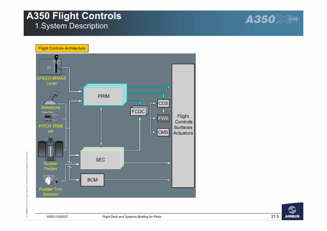
The flight controls system has:
• Flight deck controls� Sidesticks� Rudder pedals� Rudder trim selector� Pitch trim switch� Speed brake lever
The relation between the flight crew input on thesidestick and the aircraft response is called a ControlLaw.There are three control laws:� The normal law� The alternate law� The direct law.
• Three Primary Flight Computers (PRIMs).Each PRIM can provide aircraft control under normal,direct or alternate law. The PRIMs perform the� Control of flight controls� Flight Guidance (FG), A/THR and AP/FD
functions� Flight Envelope (FE) function
• Three Secondary Flight Computers (SECs). TheSECs can provide complete aircraft control in directlaw only.
The computers receive inputs from the pilot controlsor from the Auto Flight System. These inputs aretransformed into control surfaces commands whichare electrically transmitted to actuators.
The A350 has:
• Two Flight Control Data Concentrators (FCDCs)which acquire data from PRIMs and SECs and sendthem to the:� Control and Display System (CDS)� Flight Warning System (FWS)� Centralized Maintenance System (CMS)
• An Electrical Backup System (Backup ControlModule – BCM) that controls the aircraft in thecase of failure of all PRIMs and all SECs (For moreinformation, refer to Backup System)
• Flight Control Surfaces and Actuators.
System Architecture
© A
IRBU
S S.
A.S.
All
right
s re
serv
ed. C
onfid
entia
l and
pro
prie
tary
doc
umen
t.
27.5V00D11029337 Flight Deck and Systems Briefing for Pilots
A350 Flight Controls1.System Description
Flight Controls Architecture
© A
IRBU
S S.
A.S.
All
right
s re
serv
ed. C
onfid
entia
l and
pro
prie
tary
doc
umen
t.
27.6V00D11029337 Flight Deck and Systems Briefing for Pilots
A350 Flight Controls1.System Description
OperationsThe PRIMs and SECs compute the flight controlsorders.Each of these computers can perform two functions:• The computation function:
� Converts inputs that come from the flight crewor FG into orders, and computes correspondingsurface deflections that are sent to the othercomputers
� Compares the aircraft response with theobjective to check if its orders are fulfilled.
• The execution function:� Commands the surfaces actuation� Monitors the surface deflection.
One of the three PRIMs is the master. The masterPRIM computes the flight controls orders and transmitsthem to the other computers. Then, each operativePRIM and SEC activates its respective control surfacesaccordingly.
If a malfunction is detected on the master PRIM, themaster PRIM transfers the computation function toanother PRIM. The master PRIM continues to performthe execution function, depending on the malfunction.If all the PRIMs are lost, each SEC performs thecomputation and execution functions. There is nomaster SEC.
© A
IRBU
S S.
A.S.
All
right
s re
serv
ed. C
onfid
entia
l and
pro
prie
tary
doc
umen
t.
27.7V00D11029337 Flight Deck and Systems Briefing for Pilots
A350 Flight Controls1.System Description
Intentionally Left Blank
© A
IRBU
S S.
A.S.
All
right
s re
serv
ed. C
onfid
entia
l and
pro
prie
tary
doc
umen
t.
27.8V00D11029337 Flight Deck and Systems Briefing for Pilots
A350 Flight Controls1.System Description
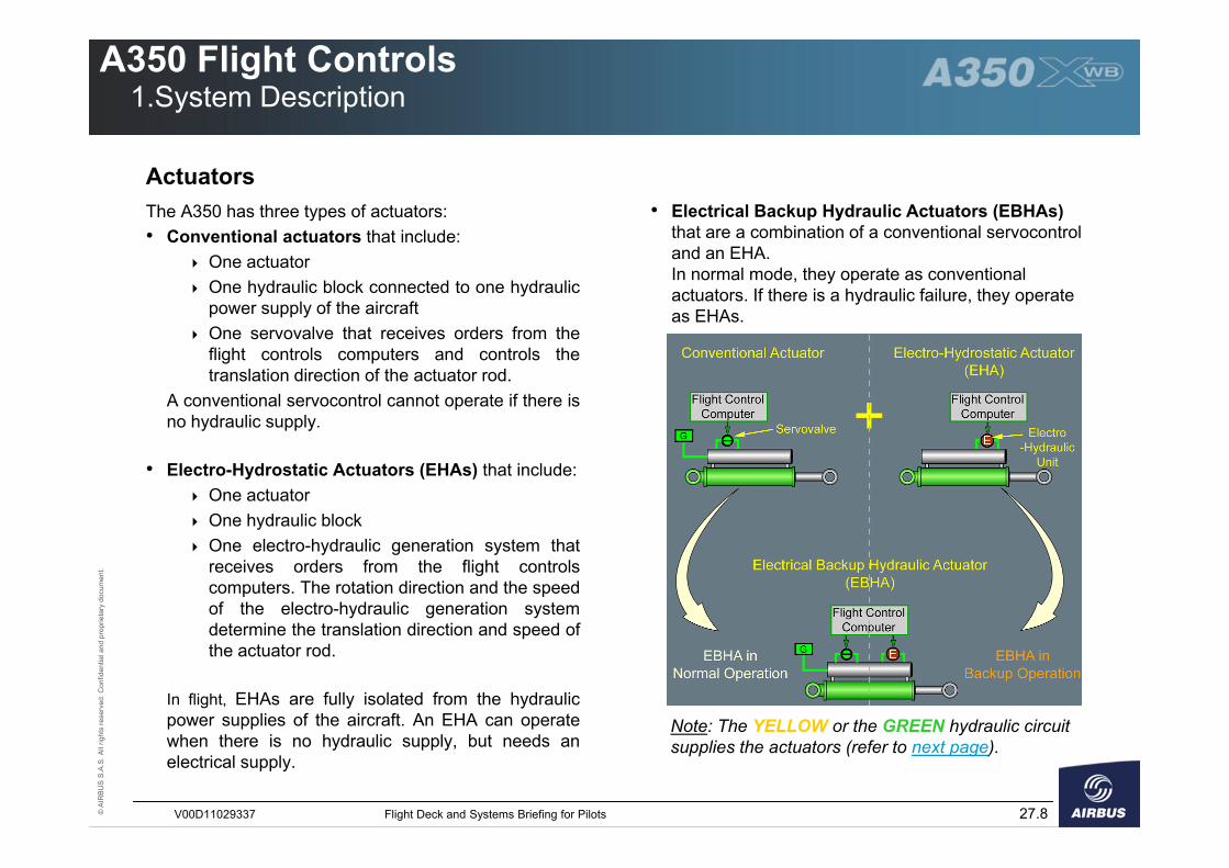
The A350 has three types of actuators:• Conventional actuators that include:
� One actuator� One hydraulic block connected to one hydraulic
power supply of the aircraft� One servovalve that receives orders from the
flight controls computers and controls thetranslation direction of the actuator rod.
A conventional servocontrol cannot operate if there isno hydraulic supply.
• Electro-Hydrostatic Actuators (EHAs) that include:� One actuator� One hydraulic block� One electro-hydraulic generation system that
receives orders from the flight controlscomputers. The rotation direction and the speedof the electro-hydraulic generation systemdetermine the translation direction and speed ofthe actuator rod.
In flight, EHAs are fully isolated from the hydraulicpower supplies of the aircraft. An EHA can operatewhen there is no hydraulic supply, but needs anelectrical supply.
Actuators• Electrical Backup Hydraulic Actuators (EBHAs)
that are a combination of a conventional servocontrol and an EHA.In normal mode, they operate as conventional actuators. If there is a hydraulic failure, they operate as EHAs.
Note: The YELLOW or the GREEN hydraulic circuit supplies the actuators (refer to next page).
© A
IRBU
S S.
A.S.
All
right
s re
serv
ed. C
onfid
entia
l and
pro
prie
tary
doc
umen
t.
27.9V00D11029337 Flight Deck and Systems Briefing for Pilots
A350 Flight Controls1.System Description
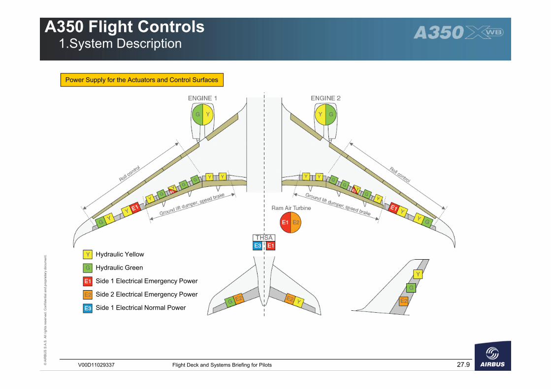
Power Supply for the Actuators and Control Surfaces
Hydraulic Yellow
Hydraulic Green
Side 1 Electrical Emergency Power
Side 2 Electrical Emergency Power
Side 1 Electrical Normal Power
© A
IRBU
S S.
A.S.
All
right
s re
serv
ed. C
onfid
entia
l and
pro
prie
tary
doc
umen
t.
27.10V00D11029337 Flight Deck and Systems Briefing for Pilots
A350 Flight Controls2.Flight Controls Functions
Primary Functions Auxiliary Functions (1/2)Lateral Control (Roll+Yaw)The following surfaces provide lateral control:• The two pairs of ailerons (Inboard and Outboard)• Spoilers 3 to 7• The rudder.
Lateral orders are sent by:• The sidesticks, to the PRIMs and SECs• The rudder pedals and pedal feel and trim unit, to the
PRIMs and SECs• The rudder trim control panel, to the SECs only• The autopilot, to the PRIMs only.
Pitch ControlThe following surfaces provide pitch control:• The elevators for short-term actions• The Trimmable Horizontal Stabilizer (THS) for long-
term actions.
Pitch orders are sent by:• The sidesticks, to the PRIMs and the SECs• The pitch trim control switches, to the PRIMs and the
SECs (only active on ground or in direct law)• The autopilot, to the PRIMs only.
Speedbrake FunctionThe objective of the speedbrake function is to increasethe drag of the aircraft with an acceptable buffet forpassenger comfort.A speedbrake demand deflects all the spoilers.The roll command has priority over the speedbrakecommand.An automatic retraction is provided, when one of thefollowing conditions is fulfilled:
� Angle-of-Attack (AOA) protection is active� Load factor is lower than 0.3 g in normal or
alternate law� A go-around is initiated.
Spoilers are lost in symmetrical pairs in the case of afailure.
Ground Spoilers FunctionThe objective of the ground spoiler function is to:
� Stick the aircraft to the ground and reduce therisk of bounce at touchdown
� Increase the efficiency of the brakes� Decelerate the aircraft.
The ground spoilers function orders the deflection of allthe spoilers.
© A
IRBU
S S.
A.S.
All
right
s re
serv
ed. C
onfid
entia
l and
pro
prie
tary
doc
umen
t.
27.11V00D11029337 Flight Deck and Systems Briefing for Pilots
A350 Flight Controls2.Flight Controls Functions
Auxiliary Functions (2/2)Aileron Droop FunctionThe objective of the aileron droop function is to increasethe high lift function performed by the slats and flaps.The inboard ailerons droop downwards when the flapsare extended. They continue to perform the rollfunction.
Load Alleviation FunctionThe objective of the load alleviation function is to reducestructure fatigue and static loads on the wing duringmanoeuvres, turbulence and gust. This function isavailable in normal law only.
Differential Flap Setting and Variable CamberThe Differential Flap Setting and Variable Camber enable to optimize the loads and drag on the wings.Small flaps deflections (4° maximum) either symmetrically or asymmetrically, enable to automatically :
� Optimize the wing camber to reduce wing loads and drag
� Perform an optimized Lateral Trim function.
© A
IRBU
S S.
A.S.
All
right
s re
serv
ed. C
onfid
entia
l and
pro
prie
tary
doc
umen
t.
27.12V00D11029337 Flight Deck and Systems Briefing for Pilots
A350 Flight Controls3.Backup System
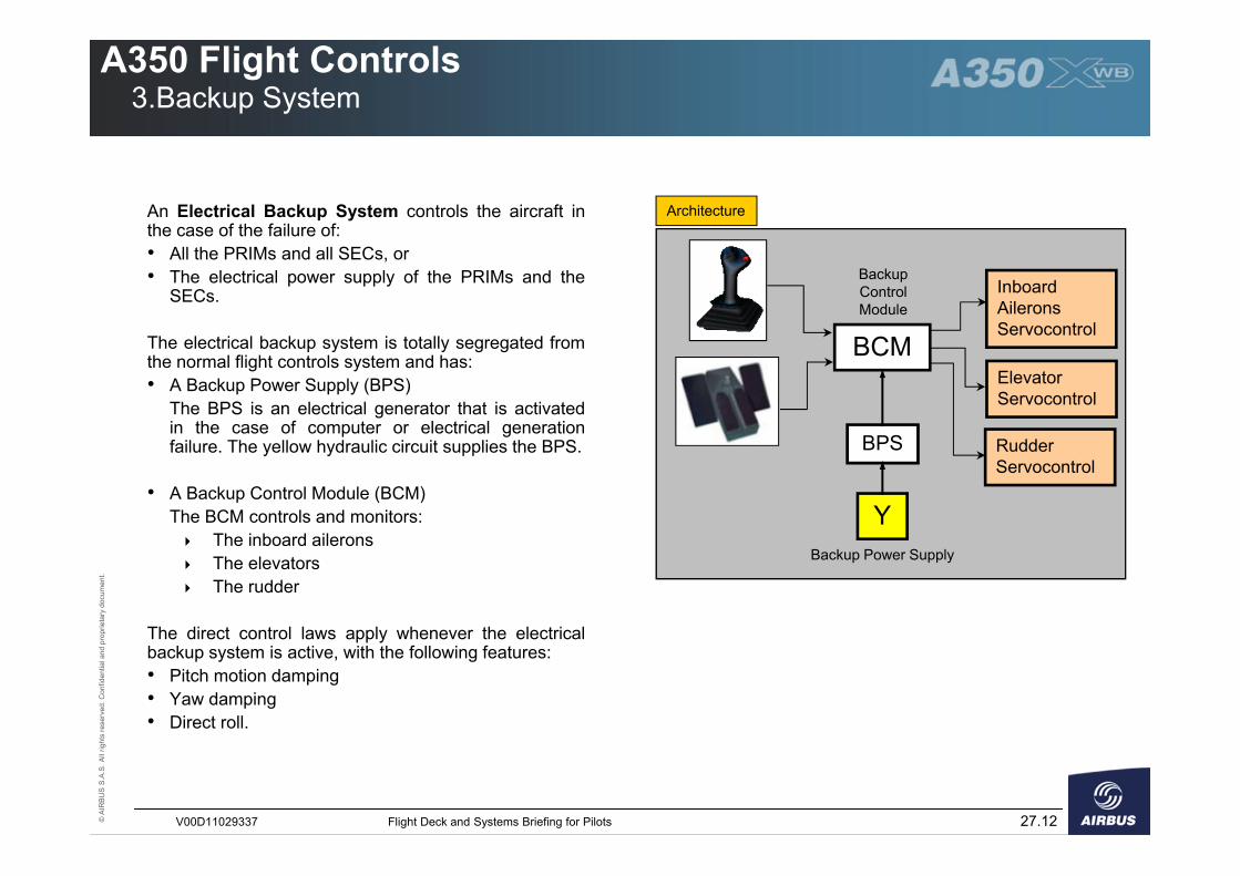
An Electrical Backup System controls the aircraft inthe case of the failure of:• All the PRIMs and all SECs, or• The electrical power supply of the PRIMs and the
SECs.
The electrical backup system is totally segregated fromthe normal flight controls system and has:• A Backup Power Supply (BPS)
The BPS is an electrical generator that is activatedin the case of computer or electrical generationfailure. The yellow hydraulic circuit supplies the BPS.
• A Backup Control Module (BCM)The BCM controls and monitors:� The inboard ailerons� The elevators� The rudder
The direct control laws apply whenever the electricalbackup system is active, with the following features:• Pitch motion damping• Yaw damping• Direct roll.
BCM
Inboard Ailerons Servocontrol
Elevator Servocontrol
Rudder Servocontrol
Y
BPS
Backup Control Module
Backup Power Supply
Architecture