Direct torque control of doubly fed induction motor using ...

Control and simulation of doubly‐fed induction generator for variable‐speed wind turbine systems based on an
integrated Finite Element approach
Qiong‐zhong Chen*, Michel Defourny#, Olivier Brüls*
*Department of Aerospace and Mechanical Engineering (LTAS),University of Liège, Belgium
# SAMTECH Headquarters, Liège, Belgium
EWEA 2011, Brussels, Belgium
1
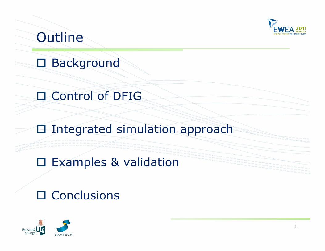
Outline
Background
Control of DFIG
Integrated simulation approach
Examples & validation
Conclusions
2
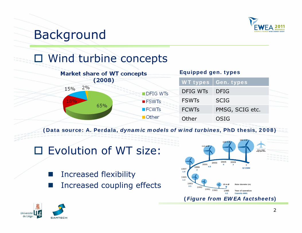
Background
Wind turbine concepts
Evolution of WT size:
Increased flexibility Increased coupling effects
(Data source: A. Perdala, dynamic models of wind turbines, PhD thesis, 2008)
WT types Gen. typesDFIG WTs DFIG
FSWTs SCIG
FCWTs PMSG, SCIG etc.
Other OSIG
Equipped gen. types
(Figure from EWEA factsheets)
3
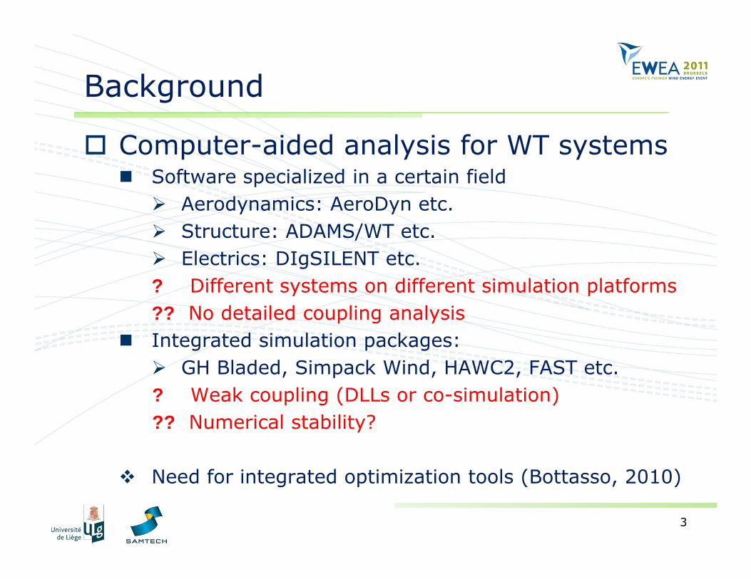
Background
Computer-aided analysis for WT systems Software specialized in a certain field Aerodynamics: AeroDyn etc. Structure: ADAMS/WT etc. Electrics: DIgSILENT etc.? Different systems on different simulation platforms?? No detailed coupling analysis
Integrated simulation packages: GH Bladed, Simpack Wind, HAWC2, FAST etc.? Weak coupling (DLLs or co-simulation)?? Numerical stability?
Need for integrated optimization tools (Bottasso, 2010)
4
Background
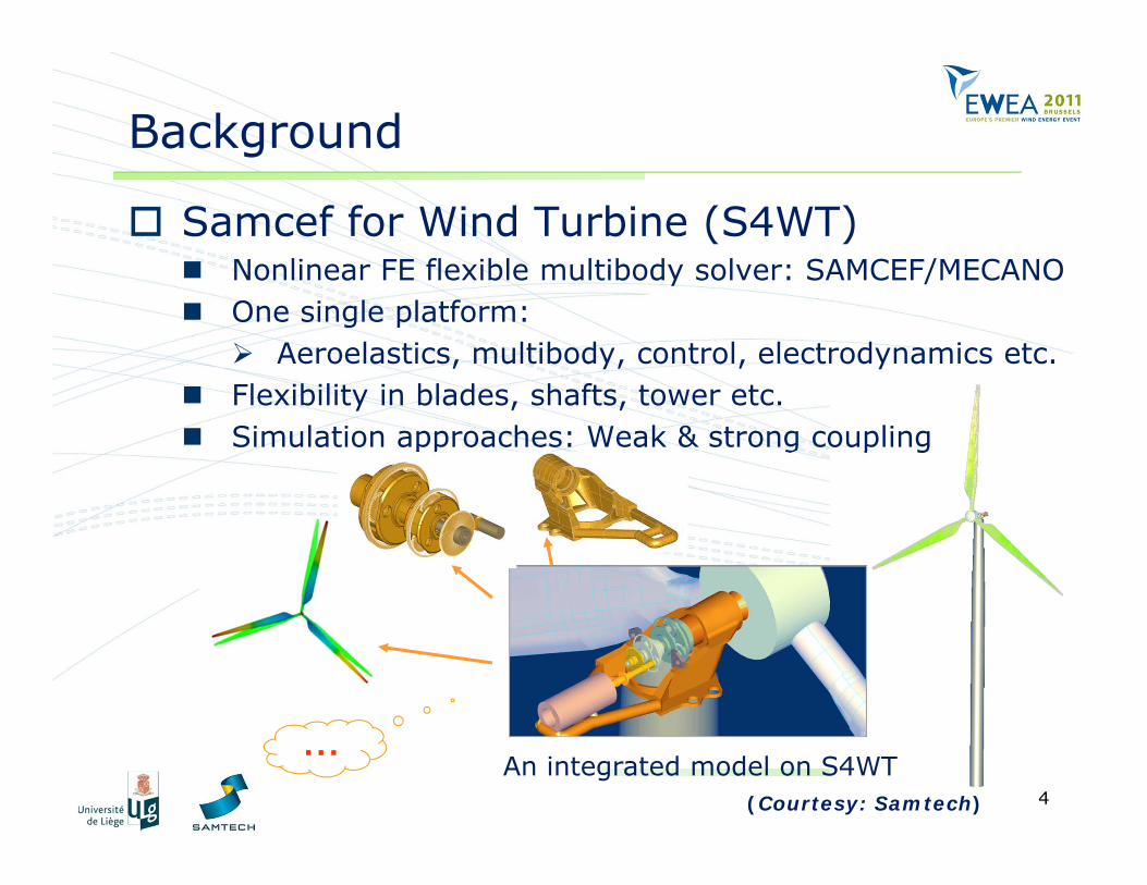
Samcef for Wind Turbine (S4WT) Nonlinear FE flexible multibody solver: SAMCEF/MECANO One single platform: Aeroelastics, multibody, control, electrodynamics etc.
Flexibility in blades, shafts, tower etc. Simulation approaches: Weak & strong coupling
An integrated model on S4WT(Courtesy: Samtech)
…
5
Highlights of the paper
Improved control strategies of DFIG WTs Grid-synchronization Power optimization
Strongly-coupled approach for mechatronic systems [B. & Golinval 2006]
Integrated structure-control-generator analysis on S4WT
Brüls, O. and Golinval, J. C. The generalized-α method in mechatronic applications. Zeitschrift für angewandte mathematik und mechanik (ZAMM) 86, 10 (2006), 748-758.
6
Control of DFIG
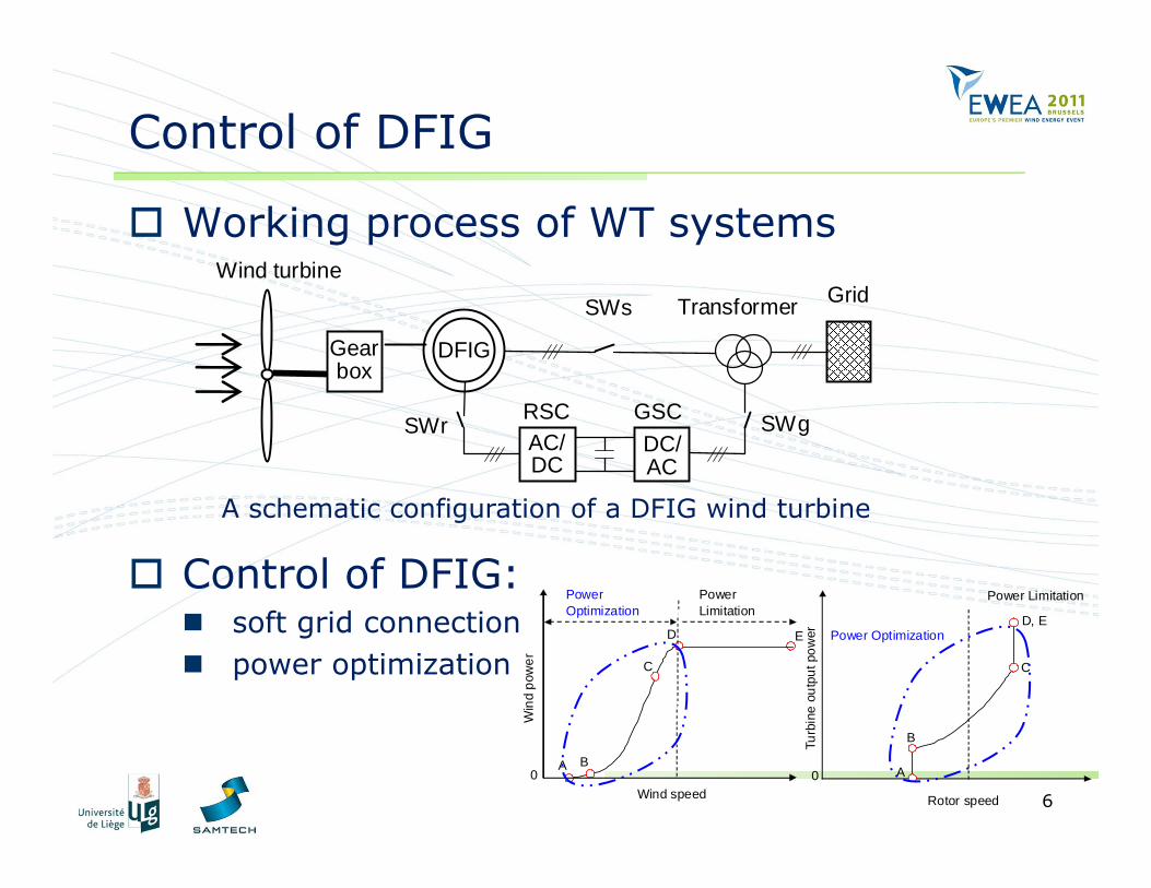
Working process of WT systems
Control of DFIG: soft grid connection power optimization
Gearbox
Grid
AC/DC
DC/ AC
SWs
SWg SWr
Transformer
DFIG
RSC GSC
Wind turbine
A schematic configuration of a DFIG wind turbine
E
A B
C
D
Power Optimization
Power Limitation
Win
d po
wer
Wind speed 0
Turb
ine
outp
ut p
ower
Rotor speed
0 A
B
C
D, E Power Optimization
Power Limitation
7
Grid synchronization control
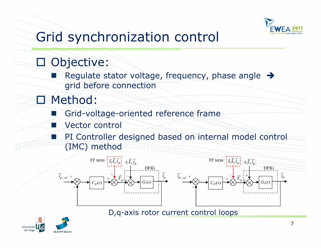
Objective: Regulate stator voltage, frequency, phase angle
grid before connection
Method: Grid-voltage-oriented reference frame Vector control PI Controller designed based on internal model control
(IMC) method
+
_ Gr(s)+ +qrVqr_refi qri
l r drs L i
+DFIG
Cqr(s)
l r drs L i
_
FF term
+
_ Gr(s)+ +drVdr_refi dri
l r qrs L i
_DFIG
Cdr(s)
l r qrs L i
+
FF term
D,q-axis rotor current control loops
8
Power control
Objective: Follow a pre-defined power-speed characteristics
profile speed regulation
Method Stator-flux-oriented reference frame
Vector control q-axis rotor current active power d-axis rotor current reactive power
IMC or pole placement method for design of controllers
9
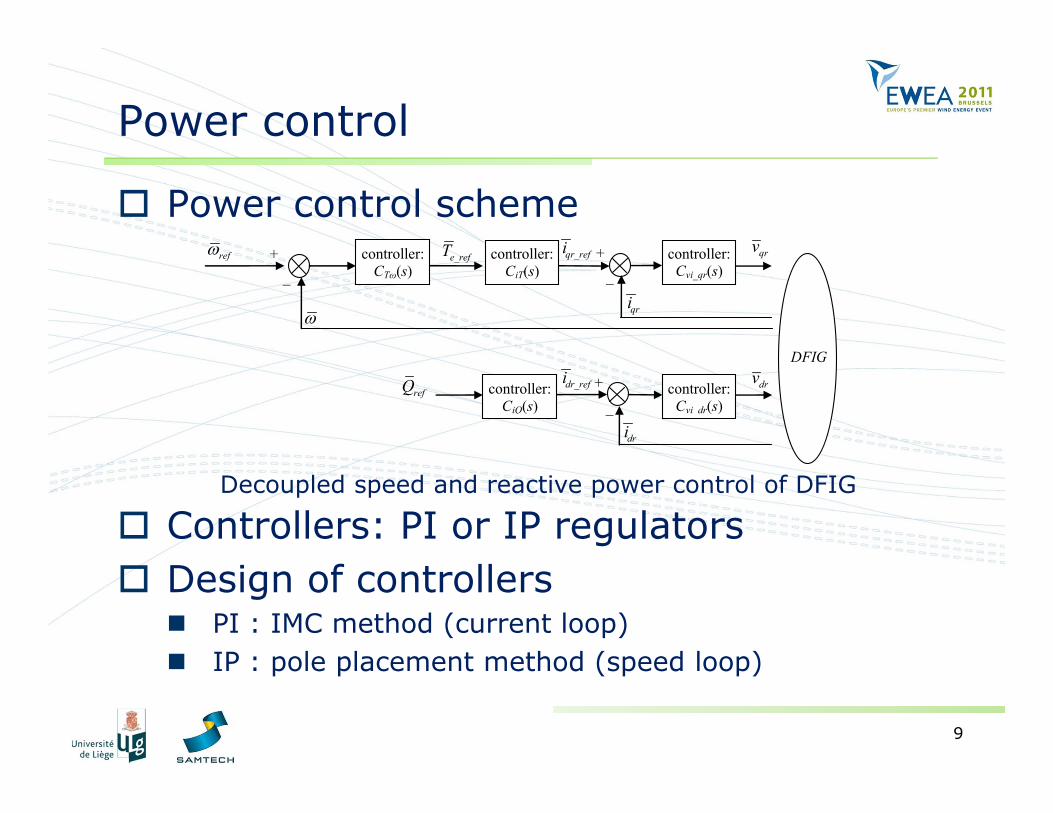
Power control
Power control scheme
Controllers: PI or IP regulators Design of controllers
PI : IMC method (current loop) IP : pole placement method (speed loop)
controller:CTω(s)
+ _
qr_refi
qri
qrvref
e_refT
dr_refi
dri
refQ drv
DFIG
controller:CiT(s)
controller:CiQ(s)
controller:Cvi_qr(s)
controller:Cvi dr(s)
+_
+_
Decoupled speed and reactive power control of DFIG
10
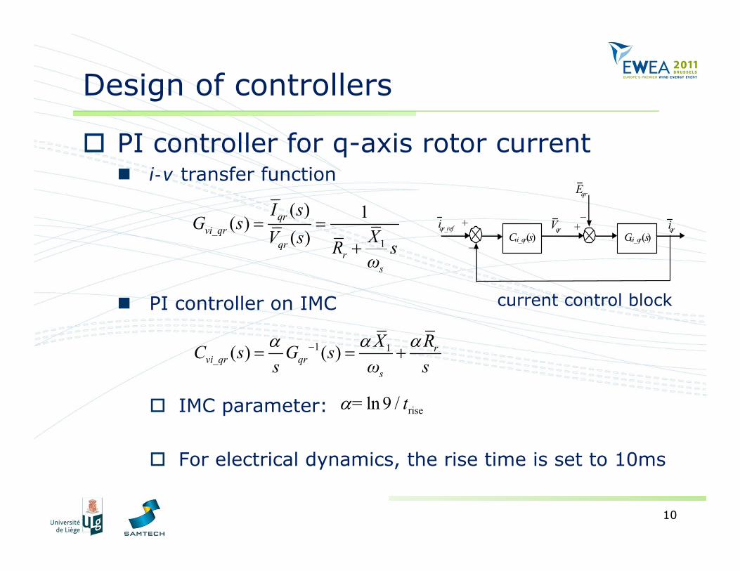
Design of controllers
PI controller for q-axis rotor current i-v transfer function
PI controller on IMC
IMC parameter:
For electrical dynamics, the rise time is set to 10ms
1
( ) 1( )( )
qrvi_qr
qrr
s
I sG s
XV s R sω
1 1( ) ( ) rvi_qr qr
s
X RC s G ss ω s
riseln 9 /= t
+
_ Cvi_qr(s) Gvi_qr(s)+̄qrVqr_refi qri
qrE
current control block
11
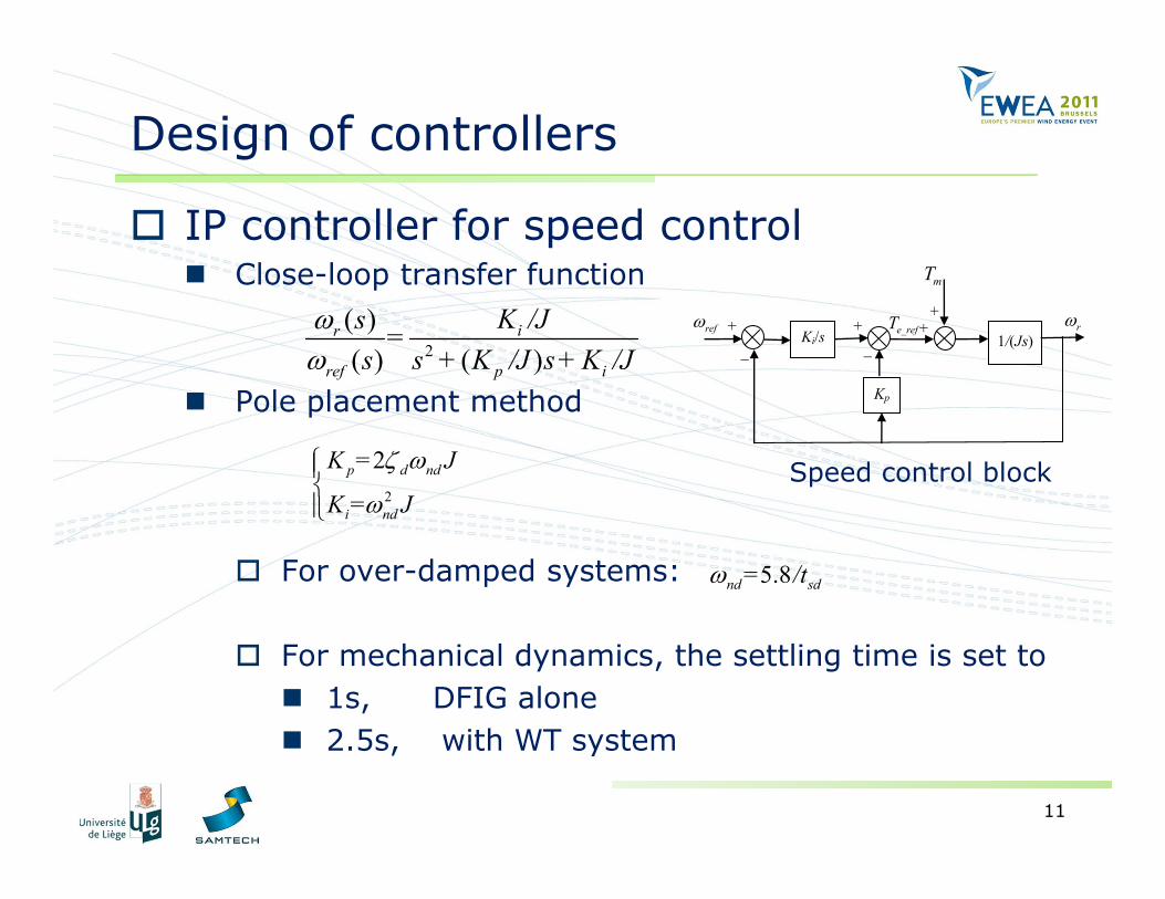
Design of controllers
IP controller for speed control Close-loop transfer function
Pole placement method
For over-damped systems:
For mechanical dynamics, the settling time is set to 1s, DFIG alone 2.5s, with WT system
+
_Ki/s 1/(Js)
+ +e_refTref
Kp
+
_
mT
r
2
( )( ) ( )
ir
ref p i
K /Js =s s + K /J s+ K /J
2
2p d nd
i nd
K = J
K = J
5.8nd sd= /t
Speed control block
12
Integrated simulation approach
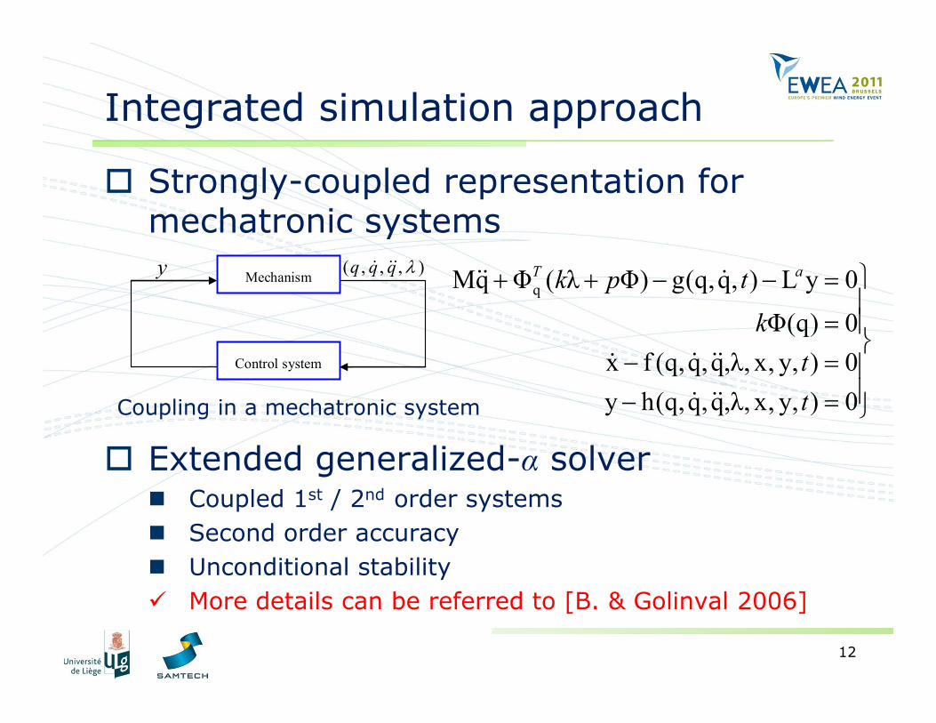
Strongly-coupled representation for mechatronic systems
Extended generalized-α solver Coupled 1st / 2nd order systems Second order accuracy Unconditional stability More details can be referred to [B. & Golinval 2006]
qMq Φ ( λ Φ) g(q,q, ) L y 0
Φ(q) 0x f (q,q,q,λ, x, y, ) 0y h(q,q,q,λ, x, y, ) 0
T ak p t
ktt
Mechanism
Control system
y ( , , , )q q q
Coupling in a mechatronic system
13
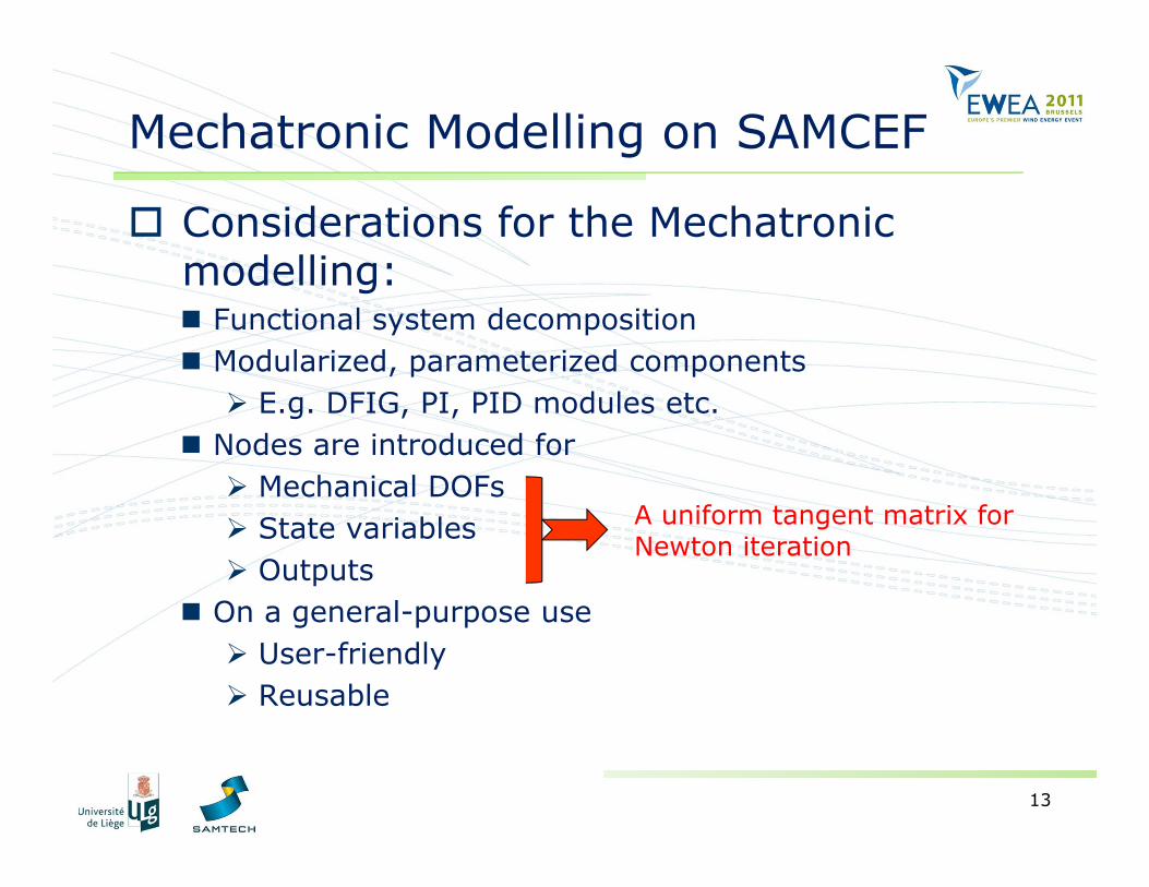
Mechatronic Modelling on SAMCEF
Considerations for the Mechatronic modelling: Functional system decomposition Modularized, parameterized components E.g. DFIG, PI, PID modules etc.
Nodes are introduced for Mechanical DOFs State variables Outputs
On a general-purpose use User-friendly Reusable
A uniform tangent matrix for Newton iteration
14
Examples & validation
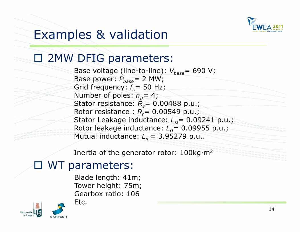
2MW DFIG parameters:
WT parameters:
Base voltage (line-to-line): Vbase= 690 V;Base power: Pbase= 2 MW;Grid frequency: fs= 50 Hz;Number of poles: np= 4;Stator resistance: Rs= 0.00488 p.u.;Rotor resistance : Rr= 0.00549 p.u.;Stator Leakage inductance: Lsl= 0.09241 p.u.;Rotor leakage inductance: Lrl= 0.09955 p.u.;Mutual inductance: Lm= 3.95279 p.u..
Inertia of the generator rotor: 100kg·m2
Blade length: 41m;Tower height: 75m;Gearbox ratio: 106Etc.
15
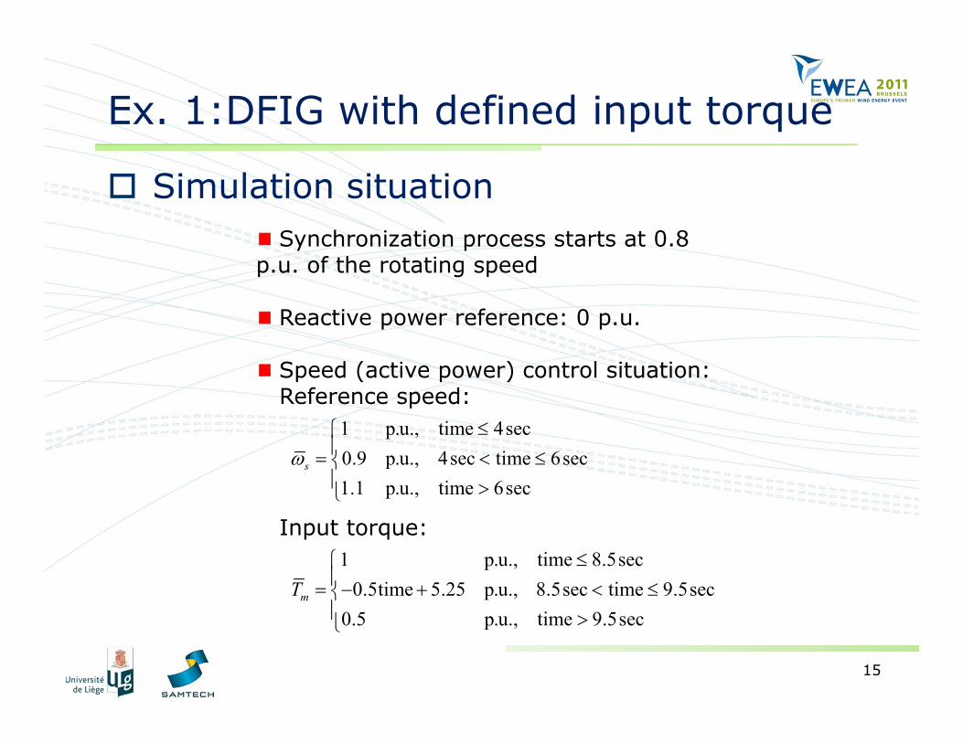
Ex. 1:DFIG with defined input torque
Simulation situationSynchronization process starts at 0.8
p.u. of the rotating speed
Reactive power reference: 0 p.u.
Speed (active power) control situation:Reference speed:
Input torque:
1 p.u., time 4sec0.9 p.u., 4sec time 6sec1.1 p.u., time 6sec
s
1 p.u., time 8.5sec0.5time 5.25 p.u., 8.5sec time 9.5sec
0.5 p.u., time 9.5sec
mT
16
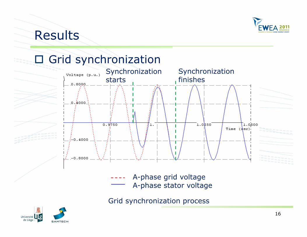
Results
Grid synchronizationSynchronization starts
Synchronization finishes
A-phase grid voltageA-phase stator voltage
Grid synchronization process
17
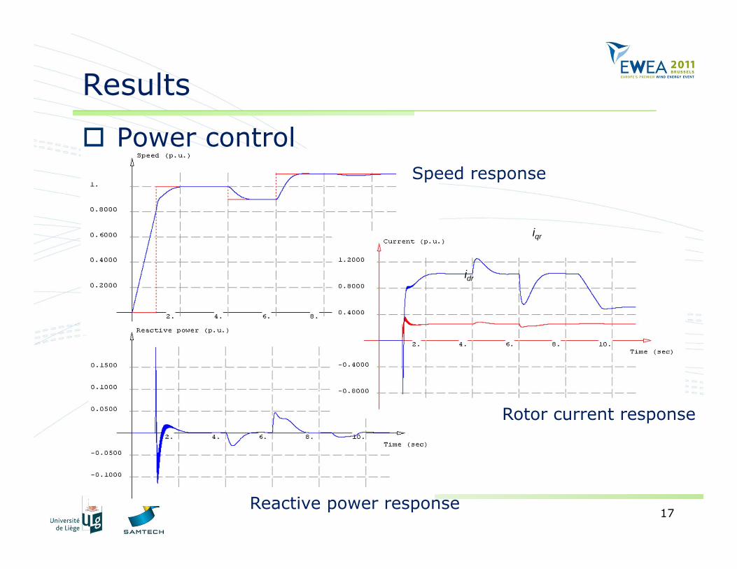
Results
Power controlSpeed response
Reactive power response
Rotor current response
iqr
idr
18
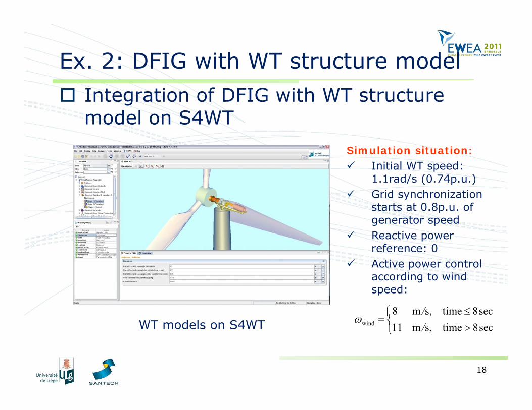
Ex. 2: DFIG with WT structure model
WT models on S4WT wind
8 m s, time 8sec11 m s, time 8sec
//
Integration of DFIG with WT structure model on S4WT
Simulation situation: Initial WT speed:
1.1rad/s (0.74p.u.) Grid synchronization
starts at 0.8p.u. of generator speed
Reactive power reference: 0
Active power control according to wind speed:
19
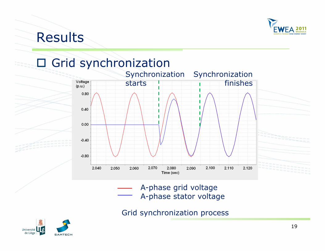
Results
Grid synchronizationSynchronization starts
Synchronization finishes
A-phase grid voltageA-phase stator voltage
Grid synchronization process
20
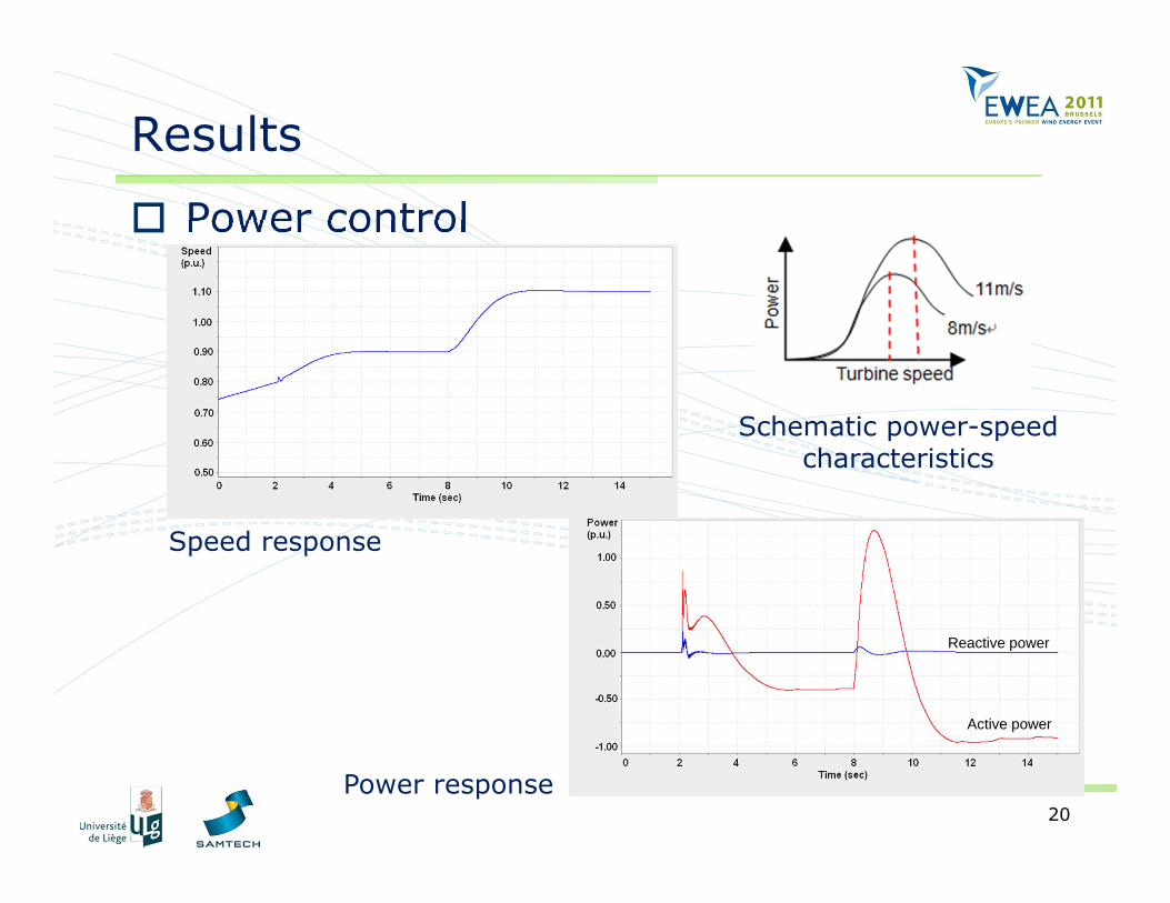
Results
Power control
Active power
Reactive power
Schematic power-speed characteristics
Speed response
Power response
21
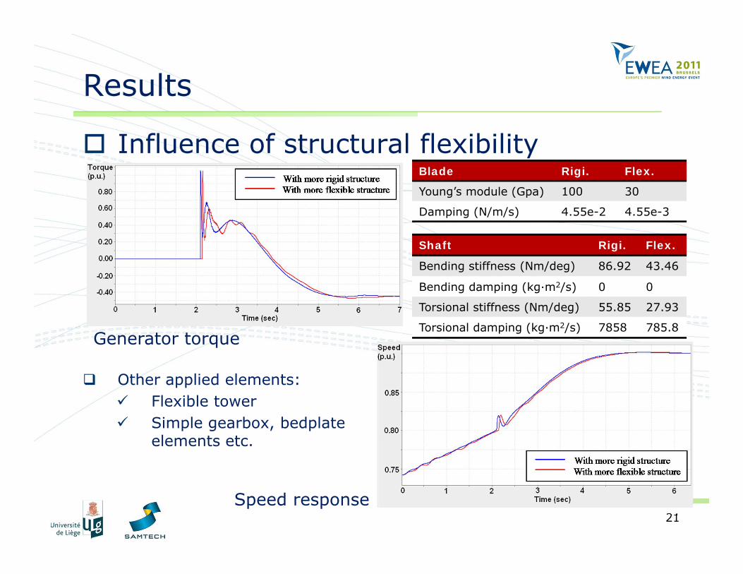
Results
Influence of structural flexibility
Generator torque
Speed response
Blade Rigi. Flex.
Young’s module (Gpa) 100 30
Damping (N/m/s) 4.55e-2 4.55e-3
Shaft Rigi. Flex.
Bending stiffness (Nm/deg) 86.92 43.46
Bending damping (kg·m2/s) 0 0
Torsional stiffness (Nm/deg) 55.85 27.93
Torsional damping (kg·m2/s) 7858 785.8
Other applied elements: Flexible tower Simple gearbox, bedplate
elements etc.
22
Conclusions
Improved control strategies for DFIG Grid synchronization & power control Solution to the difficulty in the configuration of the
controllers’ coefficients Integrated FE approach with strong coupling
instead of weak coupling Unconditional stability, less intricacy Could be less efficient
Modular models of the generator/control systems for S4WT package (on a general purpose)
Integrated variable-speed DFIG WT system model analysis and validation
23
In acknowledgement of DYNAWIND (grant number: 850533)
funded by Wallonia government, Belgium
Thank you for your Attention!