CONSTRUCTION OF PARKING LOT E … · Part of the Community College System of New ... is proposing...
149
1066 Front Street, Manchester, NH 03102 Phone (603) 206-8000 ,Fax (603) 668-5354 www.mccnh.edu | TDD Access: NH 1-800-924-3445 Part of the Community College System of New Hampshire CONSTRUCTION OF PARKING LOT E IMPROVEMENTS AT MANCHESTER COMMUNITY COLLEGE Manchester, N.H. Project: MCC14‐07C October 29, 2013
Transcript of CONSTRUCTION OF PARKING LOT E … · Part of the Community College System of New ... is proposing...

1066 Front Street, Manchester, NH 03102 Phone (603) 206-8000 ,Fax (603) 668-5354 www.mccnh.edu | TDD Access: NH 1-800-924-3445
Part of the Community College System of New Hampshire
CONSTRUCTION OF PARKING LOT E IMPROVEMENTS
AT
MANCHESTER COMMUNITY COLLEGE Manchester, N.H.
Project: MCC14‐07C
October 29, 2013

MCC14-07C Construction of Parking Lot E Improvements October 29 , 2013
Invitation to Bid – CCSNH
1
INVITATION TO BID – CCSNH
Sealed proposals will be accepted at MANCHESTER COMMUNITY COLLEGE, 1066 Front Street, Manchester, NH 03102, Attention: Susan Huard, President until 3:00 PM, prevailing time, on Tuesday, November 19, 2013 (Bids received after this time will not be accepted), for the following project:
Construction of PARKING LOT E IMPROVEMENTS
MANCHESTER, NEW HAMPSHIRE 03102
Project # MCC14-07C Description: 1.02 PROJECT DESCRIPTION A. OWNER: Manchester Community College ENGINEER: Hoyle, Tanner & Associates, Inc.
B. The Manchester Community College is proposing to construct an access drive and a 196
space paved parking lot northwest of the main building at their campus (Lot E). AND an 18 space paved extension to an existing parking lot (Lot C) that is adjacent to the Construction Technologies Building. The work includes clearing and grubbing, excavation, full depth hot bituminous pavement, installation of a drainage system, bituminous curb, pavement markings, signs, lighting, and other incidental work. The Engineer's estimate for the work is $ 390,000
C. The anticipated project schedule is to start construction in November 2013, complete
interim construction of Lot E to the crushed stone (fine Gradation) course including drainage structures and pipe by December 2013, be substantially complete by May 30, 2014 and complete final construction by June 27, 2014. See Traffic Control Plan for more details.
Plans and specifications will be available from the Community College System of New Hampshire at: www.ccsnh.edu/open-bids.
Plans and specifications are available at the following printers: Signature Press and Blueprinting, Inc., 45 Londonderry Turnpike, Rte. 28 Bypass, Hooksett, NH 03106; Reed Construction Data, 30 Technology Parkway South Suite 100 Norcross GA., 30092 Construction Summary of NH: Inc., 734 Chestnut Street, Manchester, NH 03104; Infinite Imaging: 933 Islington Street, Portsmouth, NH 03801 McGraw-Hill Construction, Dodge Plan Room: 880 Second Street, Manchester, NH 03102; Minuteman Press: 109 Gosling Road, Newington, NH 03801; Works in Progress, 20 Farrell Street, Suite 103, South Burlington, VT 05403 Community College System of New Hampshire website: www.ccsnh.edu/open-bids

MCC14-07C Construction of Parking Lot E Improvements October 29 , 2013
Invitation to Bid – CCSNH
2
BIDDERS SHOULD ACT PROMPTLY AND SUBMIT ALL QUESTIONS IN WRITING TO MATTHEW MOORE via E-MAIL [email protected].
A MANDATORY SITE WALK WILL NOT BE HELD. INTERESTED BIDDERS MAY VISIT THE SITE MONDAY TO FRIDAY 8AM TO 4PM. SIGN IN AND OUT IS REQUIRED AT THE CAMPUS SECURITY OFFICE LOCATED IN THE FRONT LOBBY AT THE MAIN ENTRANCE.
Proposals must be completed in both words and figures on forms furnished by the College, or on previously-approved, substantially-identical forms generated by computer software, which shall be submitted in a sealed envelope marked: Proposal for: “Manchester Community College –Parking Lot E Improvements MCC14-07C,” received by the College as specified no later than the date and time mentioned above.
Bidders must show three recent years’ experience with installations of a similar complexity and cost and prior experience with installations of the materials within 50 miles of the project site.
The successful bidder will be required to comply with State of New Hampshire RSA#21-1:81-a.The successful bidder will be required to furnish a 100% payment and 100% performance bond prior to execution of contract.
The award will be based on the proposal that best meets the needs of the college. Factors included will be the cost, completeness of the proposal, quality of the technology provided, and experience of the contractor and installation team. The college reserves the right to waive any informality in or to reject any or all proposals.
Category Possible Points*
1. Cost of Base Proposal 70 2. Quality of the related projects/areas of expertise/experience 30
Grand Total 100*
*Maximum points for the best and so forth. Difference between scores is based on how close they are to one another. The College reserves the right to waive any and all informalities in its best interest.
All contract documents can be found on the CCSNH website at www.ccsnh.edu/open-bids. Before your submission, always check for any addenda or other materials that may have been issued which would affect the invitation to bid by checking the CCSNH website at www.ccsnh.edu/open-bids.
Matthew Moore, PE,
Director of Capital Projects Community College System of New Hampshire
END OF DOCUMENT


COMMUNITY COLLEGE SYSTEM OF NEW HAMPSHIRE INSURANCE REQUIRED OF CONTRACTORS
TYPES OF INSURANCE REQUIRED For the purposes of this document the term Contractor shall include each and every contractor, subcontractor, and sub-subcontractor utilized by the General Contractor to complete the contruction project.
General Liability Insurance Commercial General Liability insurance covers claims for Bodily Injury and Property
damage. CCSNH requires GL insurance when: ♦ A contractor will be working at a CCSNH location. ♦ The contractor has third parties on CCSNH’s premises who could be injured
or cause injury to others. ♦ Their “completed work” (building; renovations; HVAC; etc.) may fail, causing
bodily injury or property damage ♦ The contractor is likely to subcontract part of their work
Automobile Liability Insurance A Business Auto Liability insurance is required when a Contractor and/or their employees and subcontractors will operate, maintain, load or unload vehicles as part of their contracted work on any campus. As such, any Contractor who drives onto CCSNH’s owned or leased property should be required to provide evidence of a Commercial Automobile Liability insurance.
Umbrella/Excess Liability Insurance An Umbrella/Excess policy is required when CCSNH is requesting total per occurrence and aggregate limits of liability that are higher than those carried by the Contractor in their “primary” General Liability, Auto Liability or Employer’s Liability (WC) policies – which is always the case. Note: General Liability policies typically provide limits of $1,000,000 per occurrence and $2,000,000 aggregate. Automobile liability policies generally provide a $1,000,000 “combined single” (CSL) limit.
Workers’ Compensation Insurance CCSNH should request evidence of Workers’ Compensation (including Employers Liability coverage) for EACH AND EVERY Contractor. Evidence of workers’ compensation insurance from subcontractors and sub-subcontractors is the responsibility of General Contractor.
Property Insurance When a new building is being contructed or an existing building is being renovated, coverage for the building material and the structure itself is provided by CCSNH.

2
However, the Contractor, all Subcontractors, and Sub-subcontractors should be aware that this “Builder’s Risk” coverage does not provide coverage for the Contractor’s business personal property – tools, equipment, etc. As such, they need to provide coverage for this exposure themselves.
Pollution Liability Insurance Pollution legal liability insurance may be required if there is a chance that the Contractor may cause a first party or third party liabilty or property damage claim arising out of the “pollution” of any land, water or buildings by any type of “hazardous waste” material through their own actions or actions of another acting on their behalf. Professional/Errors & Omissions Liability Insurance Professional or E&O insurance is required of all Architects and Engineers who provide the design and engineering for buildings and other structures.
LIMITS OF INSURANCE REQUIRED The following insurance requirements are to be used as a guide for CCSNH’s contracts with Contractors/Sub-Contractors. The insurance requirements and indemnification language that are ultimately incorporated into the contracts should be tailored to the operations and exposures with respect to the construction being performed in order to protect the interests of CCSNH and its Affiliated Entities. Commercial General Liability: Contractor agrees to maintain in full force during the term of this contract and until the completion of this project Commercial General Liability insurance with the following minimum limits of liability: $1,000,000. per occurrence Limit for bodily injury/property damage $1.000,000 per occurrence Personal and advertising injury $2,000,000 aggregate Products/completed operations
$2,000,000 aggregate Policy aggregate $5,000 per person Medical expense These limits shall be provided per project/per job.
Automobile Liability Insurance: Contractor agrees to maintain in full force during the term of this contract and until the completion of this project Commercial Automobile Liability insurance for all owned, non-owned, and hired vehicles/trucks. The minimum limit of liability shall be $1,000,000 each accident, combined single limit for Bodily Injury and Property Damage. Workers’ Compensation Insurance: Contractor agrees to maintain in full force and effect Workers’ Compensation insurance which provides statutory coverage for Workers’ Compensation claims and Employers’ Liability insurance subject to minimum limits of : $500,000 each accident Bodily injury by accident

3
$500,000 each employee Bodily injury by disease $500,000 policy limit Bodily injury by disease or the minimum limits required by Contractor’s Umbrella insurer. Umbrella Liability Insurance: Contractor agrees to maintain in full force and affect Umbrella Liability insurance which provides excess following form coverage over the underlying Commercial General Liability, Automobile Liability, and Employers Liability policies previously described. The Umbrella/Excess policy will provide minimum limits of liability of $5,000,000 per occurrence and aggregate - and the aggregate limit should be provided on a “per project or job” or location basis. Professional Liability Insurance: Architect/Engineer agrees to maintain in full force during the term of this contract and for a period of five years after the completion of this project, Architects and Engineers Professional Liability (Errors and Omissions) insurance subject to a minimum per occurrence and aggregate limit of $3,000,000. Note: The scope of coverage and limit provided by the policy shall encompass the Architect/Engineers obligations as defined in the project agreement. Personal Property Insurance: Contractor is responsible for the purchase and maintenance of “property” insurance on a “replacement cost basis” to cover all of “property” (tools, equipment, materials, etc.) owned by the Contractor. Note: The contract should indicate that the property will “be the sole responsibility and risk of Contractor” and that “CCSNH shall not be liable for any loss, damage, or theft to such property.” Other Insurance: CCSNH reserves the right to require the Contractor to maintain additional insurance coverage as deemed necessary by the nature of the contract and from time to time during the contract period.
OTHER INSURANCE ISSUES AND REQUIRMENTS: General Requirements Contractor is required to maintain, during the life of this contract with CCSNH, insurance that will adequately protect CCSNH and the Contractor against the exposures inherent to the contract and construction project. The insurance policies provided by Contractor must be underwritten by an insurance company that is financially sound and adequately rated (“A-” or higher) by one or more of the leading financial rating services including AM Best, Moody’s and/or Standard & Poors. The insurance companies utilized by the Contractor must be licensed to do business in the State of New Hampshire. If such insurance is provided by “self-insurance” or a Captive insurance company, adequate financial data should be provided to assure CCSNH of the Contractor’s ability to fund all deductibles, retentions and claims that occur.
4
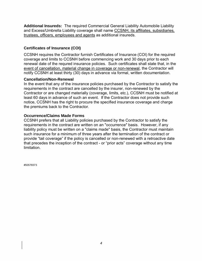
Additional Insureds: The required Commercial General Liability Automobile Liability and Excess/Umbrella Liability coverage shall name CCSNH, its affiliates, subsidiaries, trustees, officers, employees and agents as additional insureds. Certificates of Insurance (COI) CCSNH requires the Contractor furnish Certificates of Insurance (COI) for the required coverage and limits to CCSNH before commencing work and 30 days prior to each renewal date of the requred insurance policies. Such certificates shall state that, in the event of cancellation, material change in coverage or non-renewal, the Contractor will notify CCSNH at least thirty (30) days in advance via formal, written documentation. Cancellation/Non-Renewal In the event that any of the insurance policies purchased by the Contractor to satisfy the requirements in the contract are cancelled by the insurer, non-renewed by the Contractor or are changed materially (coverage, limits, etc.), CCSNH must be notified at least 60 days in advance of such an event. If the Contractor does not provide such notice, CCSNH has the right to procure the specified insurance coverage and charge the premiums back to the Contractor. Occurrence/Claims Made Forms CCSNH prefers that all Liability policies purchased by the Contractor to satisfy the requirements in the contract are written on an "occurrence" basis. However, if any liability policy must be written on a "claims made" basis, the Contractor must maintain such insurance for a minimum of three years after the termination of the contract or provide “tail coverage” if the policy is cancelled or non-renewed with a retroactive date that precedes the inception of the contract - or “prior acts” coverage without any time limitation. #50576573

NAME OF BIDDING CONTRACTOR
LUMP SUM GRAND TOTAL
THE COLLEGE SYSTEM RESERVES THE RIGHT TO AWARD ANY OR ALL ITEMS.
PROPOSAL FORM – LUMP SUM GRAND TOTAL BID
MANCHESTER COMMUNITY COLLEGE
CONSTRUCTION OF PARKING LOT E IMPROVEMENTS PROJECT # MCC14-07C
1066 FRONT STREET MANCHESTER, NEW HAMPSHIRE 03102
PROPOSAL DUE: NOVEMBER 19, 2013
MCC14-07C Construction of Parking Lot E Improvements October 29, 2013
Proposal Form – Lump Sum Grand Total – CCSNH 1
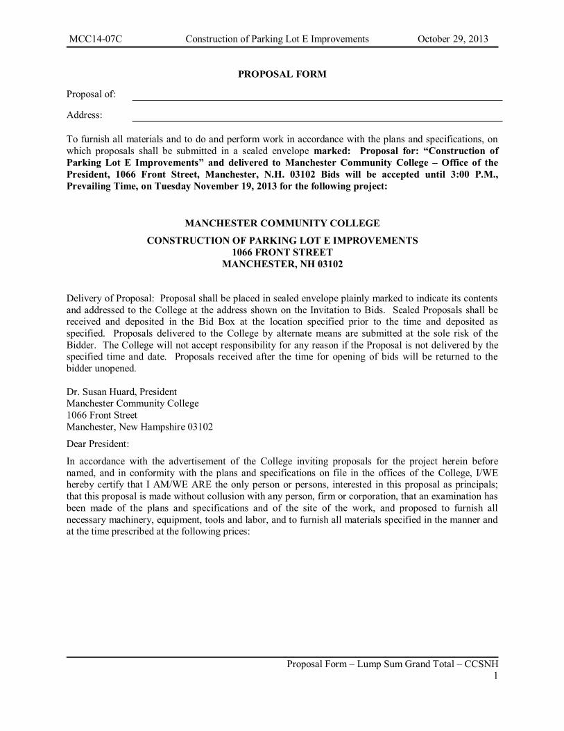
PROPOSAL FORM
Proposal of: Address: To furnish all materials and to do and perform work in accordance with the plans and specifications, on which proposals shall be submitted in a sealed envelope marked: Proposal for: “Construction of Parking Lot E Improvements” and delivered to Manchester Community College – Office of the President, 1066 Front Street, Manchester, N.H. 03102 Bids will be accepted until 3:00 P.M., Prevailing Time, on Tuesday November 19, 2013 for the following project:
MANCHESTER COMMUNITY COLLEGE
CONSTRUCTION OF PARKING LOT E IMPROVEMENTS 1066 FRONT STREET
MANCHESTER, NH 03102
Delivery of Proposal: Proposal shall be placed in sealed envelope plainly marked to indicate its contents and addressed to the College at the address shown on the Invitation to Bids. Sealed Proposals shall be received and deposited in the Bid Box at the location specified prior to the time and deposited as specified. Proposals delivered to the College by alternate means are submitted at the sole risk of the Bidder. The College will not accept responsibility for any reason if the Proposal is not delivered by the specified time and date. Proposals received after the time for opening of bids will be returned to the bidder unopened. Dr. Susan Huard, President Manchester Community College 1066 Front Street Manchester, New Hampshire 03102
Dear President:
In accordance with the advertisement of the College inviting proposals for the project herein before named, and in conformity with the plans and specifications on file in the offices of the College, I/WE hereby certify that I AM/WE ARE the only person or persons, interested in this proposal as principals; that this proposal is made without collusion with any person, firm or corporation, that an examination has been made of the plans and specifications and of the site of the work, and proposed to furnish all necessary machinery, equipment, tools and labor, and to furnish all materials specified in the manner and at the time prescribed at the following prices:
MCC14-07C Construction of Parking Lot E Improvements October 29, 2013
Proposal Form – Lump Sum Grand Total – CCSNH 2
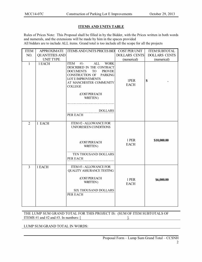
ITEMS AND UNITS TABLE Rules of Prices Note: This Proposal shall be filled in by the Bidder, with the Prices written in both words and numerals, and the extensions will be made by him in the spaces provided All bidders are to include ALL items. Grand total is too include all the scope for all the projects
ITEM NO.
APPROXIMATE QUANTITIES AND
UNIT TYPE
ITEMS AND UNITS PRICES BID COST PER UNIT DOLLARS CENTS
(numerical)
ITEM SUBTOTAL DOLLARS CENTS
(numerical) 1 1 EACH ITEM #1- ALL WORK
DESCRIBED IN THE CONTRACT DOCUMENTS TO PROVDE CONSTRUCTION OF PARKING LOT E IMPROVEMENTS AT MANCHESTER COMMUNITY COLLEGE
(COST PER EACH WRITTEN )
DOLLARS PER EACH
1PER EACH
$ .
2 1 EACH ITEM #2 - ALLOWANCE FOR UNFORESEEN CONDITIONS
(COST PER EACH WRITTEN )
TEN THOUSAND DOLLARS
PER EACH
1 PER EACH
$10,000.00
3 1 EACH ITEM #3 - ALLOWANCE FOR QUALITY ASSURANCE TESTING
(COST PER EACH
WRITTEN )
SIX THOUSAND DOLLARS PER EACH
1 PER EACH
$6,000.00
THE LUMP SUM GRAND TOTAL FOR THIS PROJECT IS: (SUM OF ITEM SUBTOTALS OF ITEMS #1 and #2 and #3. In numbers: [ ]. LUMP SUM GRAND TOTAL IN WORDS:

MCC14-07C Construction of Parking Lot E Improvements October 29, 2013
Proposal Form – Lump Sum Grand Total – CCSNH 3
______________________________________________________________________________________
The award will be based on the proposal that best meets the needs of the college. Factors included will be the cost, completeness of the proposal, quality of the technology provided, and experience of the contractor and installation team. The college reserves the right to waive any informality in or to reject any or all proposals.
The Chancellor reserves the right to waive any and all informalities in the best interests of the College.
It is further proposed:
To execute the form of contract and to complete the project on or before June 27, 2014 and in accordance with agreed to extensions based on weather conditions. To furnish a contract bond in the amount of one hundred percent (100%) of the contract award as security for the completion of the contract in accordance with the plans and specifications and contract documents. The form of bond shall be that provided for by the Department, and the surety shall be acceptable to the Chancellor.
To guarantee all of the work performed under this contract to be done in accordance with the plans and specifications and the contract documents.
The undersigned acknowledges receipt of the following addenda, issued during the bidding time, and states that these have been incorporated in this proposal:
Addendum No.___ dated
Addendum No.___ dated
MCC14-07C Construction of Parking Lot E Improvements October 29, 2013
Proposal Form – Lump Sum Grand Total – CCSNH 4
IF A PARTNERSHIP
Signature of Bidder: (printed name and title)
Partnership Name & Address Names and Addresses of Members of the Partnership:

MCC14-07C Construction of Parking Lot E Improvements October 29, 2013
Proposal Form – Lump Sum Grand Total – CCSNH 5
IF AN LLC
Signature of Bidder: (printed name and title)
LLC Name & Address: Names and Addresses of Members and Managers:

MCC14-07C Construction of Parking Lot E Improvements October 29, 2013
Proposal Form – Lump Sum Grand Total – CCSNH 6
IF A CORPORATION
Signature of Bidder: (printed name and title) Corporation Name & Address:
Incorporated under the laws of the State of Names and Addresses of Corporate Officers: [A bid by a person who affixes to his/her signature, the word "President," "Secretary,” "Agent" or other designation, without disclosing whom he/she is representing if other than the contracting entity noted above, may be held to the bid of the individual signing.] President
Name:
Address: Secretary
Name:
Address: (Enter Designation of another Corporate Officer below, such as Vice President or Agent …..)
Name:
Address:
MCC14-07C Construction of Parking Lot E Improvements October 29, 2013
Proposal Form – Lump Sum Grand Total – CCSNH 7
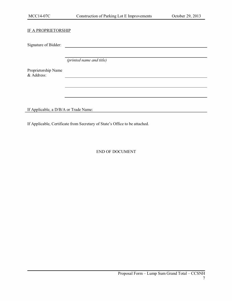
IF A PROPRIETORSHIP
Signature of Bidder: (printed name and title)
Proprietorship Name & Address: If Applicable, a D/B/A or Trade Name:
If Applicable, Certificate from Secretary of State’s Office to be attached.
END OF DOCUMENT


Hoyle, Tanner Project No. 920601.07 TS-1 Technical Specifications
TECHNICAL SPECIFICATIONS
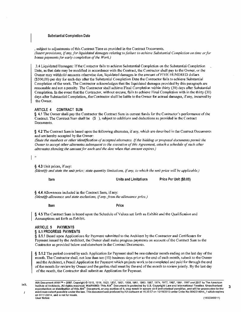
All work shall be in accordance with State of New Hampshire, Department of Transportation NHDOT Standard Specifications for Road and Bridge Construction, approved and adopted in August 2010 (Standard Specifications). The NHDOT specifications are hereby amended as follows: 1. Delete Division 100-General Provisions in its entirety. The Applicable provisions
within the AIA Document A201-2007 shall apply. Should any descrepancies develop between the technical specifications and the AIA document, the AIA document shall govern.
2. Substitute “Owner’s Representative” for “Engineer”, “Department”, “State”, “Bureau of Bridge Design”, “Bureau of Materials and Research” or “NHDOT Compliance Review Officer” throughout the specifications.
All applicable portions of Sections 201 through 699 from the NHDOT Standard Specifications (English Units) apply to this Project, unless modified by Supplemental Specifications or Special Provisions in this document. The NHDOT Specifications are periodically supplemented with updates posted on the NHDOT website at www.nh.gov./dot/org/projectdevelopment/highwaydesign/specifications/supplementals/index.htm. All applicable supplemental specifications for sections 201 through 699 available at the time that the bid is due will be considered part of this contract specification. The following plans from NHDOT Standard Plans for Road and Bridge Construction are also considered a part of this contract: CR-2 Bituminous Curb Type B DR-1 Type “B” Grate and Frame DR-2 Manhole Cover and Frame PM-1 Layout Details PM-2 Tolerances for Pavement Marking Lines PM-11 Accessible Parking Detail These lists are not all inclusive and do not relieve the Contractor from complying with any or all NHDOT specifications or plans referred to by the contract documents or referred to by sections of the NHDOT specifications that apply. It is the contractor’s responsibility to obtain copies of these specifications and plans. These plans may also be downloaded, free of charge, from the NHDOT website at http://www.nh.gov./dot/org/projectdevelopment/highwaydesign/standardplans/index.htm NHDOT Standard Specifications for Road and Bridge Construction and NHDOT Standard
Plans for Road and Bridge Construction may be purchased from NHDOT, Records Section, 1 Hazen Drive, P.O. Box 483, Concord, NH 03302-0483, Phone No. 603-271-3514. These specifications may also be downloaded, free of charge, from the NHDOT website
at http://www.nh.gov./dot/org/projectdevelopment/highwaydesign/specifications/index.htm

Hoyle, Tanner Project No. 920601.07 SP-1 Special Provisions
SPECIAL PROVISIONS
The following Special Provisions are to be used in conjunction with the NHDOT Standard Specifications and are herein made a part of the Contract Documents and apply to this project:
Special Provisions Section Description 604 Catch Basins, Drop Inlets and Manholes SP-2 1010.30 Quality Assurance Testing SP-3 16402 Site Electrical Work SP-5
Hoyle, Tanner Project No. 920601.07 SP-2 Special Provisions
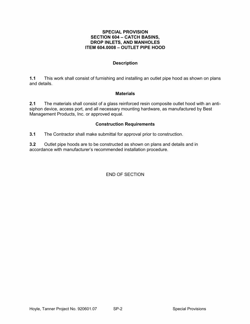
SPECIAL PROVISION SECTION 604 – CATCH BASINS, DROP INLETS, AND MANHOLES
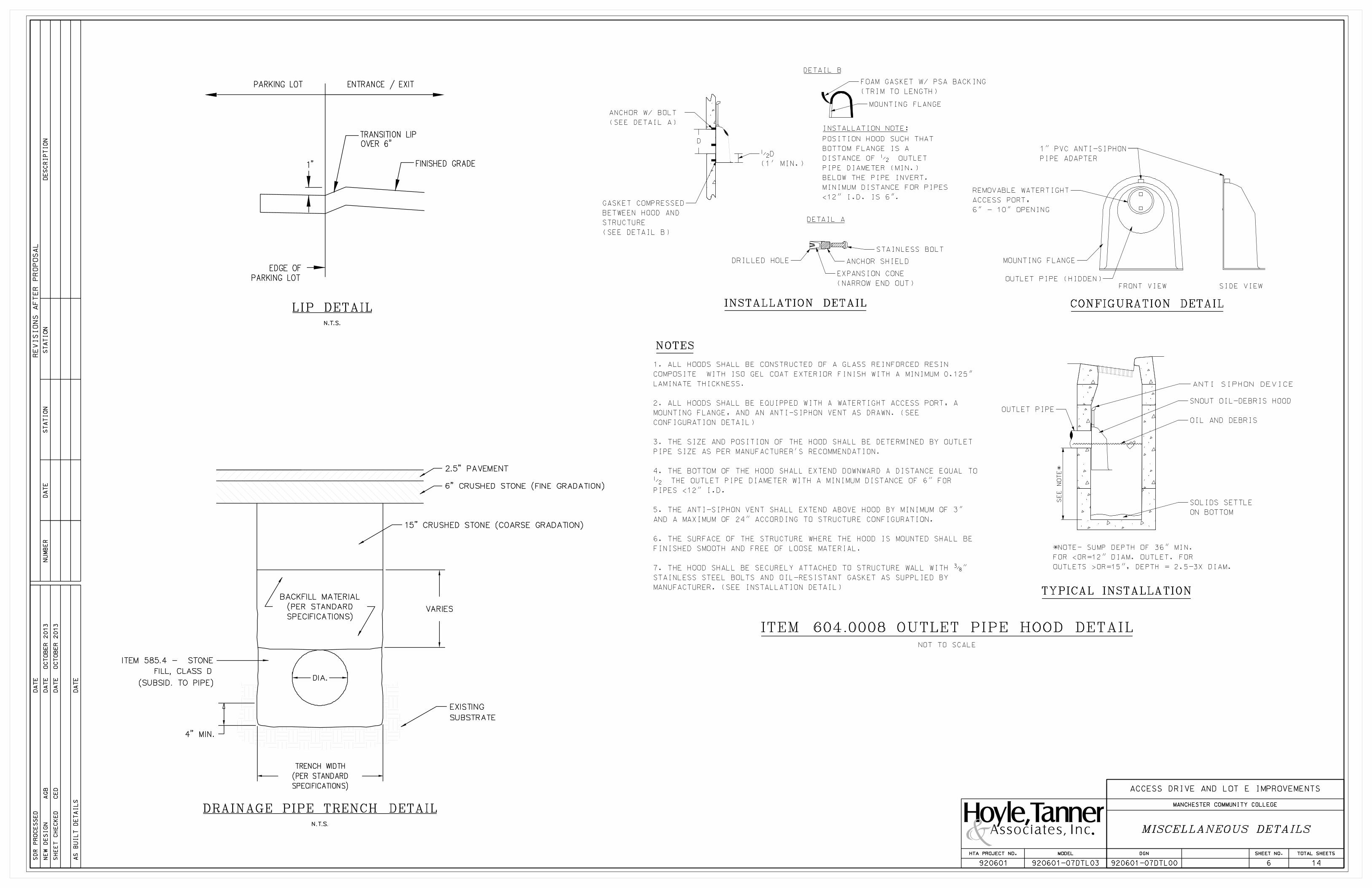
ITEM 604.0008 – OUTLET PIPE HOOD
Description
1.1 This work shall consist of furnishing and installing an outlet pipe hood as shown on plans and details.
Materials
2.1 The materials shall consist of a glass reinforced resin composite outlet hood with an anti-siphon device, access port, and all necessary mounting hardware, as manufactured by Best Management Products, Inc. or approved equal.
Construction Requirements
3.1 The Contractor shall make submittal for approval prior to construction.
3.2 Outlet pipe hoods are to be constructed as shown on plans and details and in accordance with manufacturer’s recommended installation procedure.
END OF SECTION
Hoyle, Tanner Project No. 920601.07 SP-3 Special Provisions
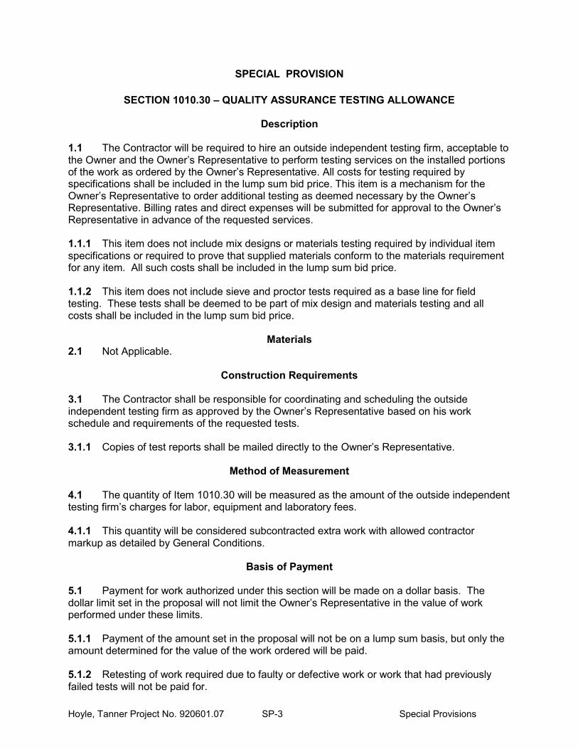
SPECIAL PROVISION
SECTION 1010.30 – QUALITY ASSURANCE TESTING ALLOWANCE
Description
1.1 The Contractor will be required to hire an outside independent testing firm, acceptable to the Owner and the Owner’s Representative to perform testing services on the installed portions of the work as ordered by the Owner’s Representative. All costs for testing required by specifications shall be included in the lump sum bid price. This item is a mechanism for the Owner’s Representative to order additional testing as deemed necessary by the Owner’s Representative. Billing rates and direct expenses will be submitted for approval to the Owner’s Representative in advance of the requested services. 1.1.1 This item does not include mix designs or materials testing required by individual item specifications or required to prove that supplied materials conform to the materials requirement for any item. All such costs shall be included in the lump sum bid price. 1.1.2 This item does not include sieve and proctor tests required as a base line for field testing. These tests shall be deemed to be part of mix design and materials testing and all costs shall be included in the lump sum bid price.
Materials 2.1 Not Applicable.
Construction Requirements
3.1 The Contractor shall be responsible for coordinating and scheduling the outside independent testing firm as approved by the Owner’s Representative based on his work schedule and requirements of the requested tests. 3.1.1 Copies of test reports shall be mailed directly to the Owner’s Representative.
Method of Measurement
4.1 The quantity of Item 1010.30 will be measured as the amount of the outside independent testing firm’s charges for labor, equipment and laboratory fees. 4.1.1 This quantity will be considered subcontracted extra work with allowed contractor markup as detailed by General Conditions.
Basis of Payment
5.1 Payment for work authorized under this section will be made on a dollar basis. The dollar limit set in the proposal will not limit the Owner’s Representative in the value of work performed under these limits. 5.1.1 Payment of the amount set in the proposal will not be on a lump sum basis, but only the amount determined for the value of the work ordered will be paid. 5.1.2 Retesting of work required due to faulty or defective work or work that had previously failed tests will not be paid for.

Hoyle, Tanner Project No. 920601.07 SP-4 Special Provisions
5.2 The Bidder’s attention is called to the dollar amount inserted in the proposal under these items, which dollar amount is the allowance the OWNER has set up for the special work. This figure must not be altered by the Bidder on the proposal, and must be included to obtain the grand total of the bid. Pay item and units: 1010.30 Quality Assurance Testing Allowance $6000
END OF SECTION
Hoyle, Tanner Project No. 920601.07 SP-5 Special Provisions
SPECIAL PROVISION
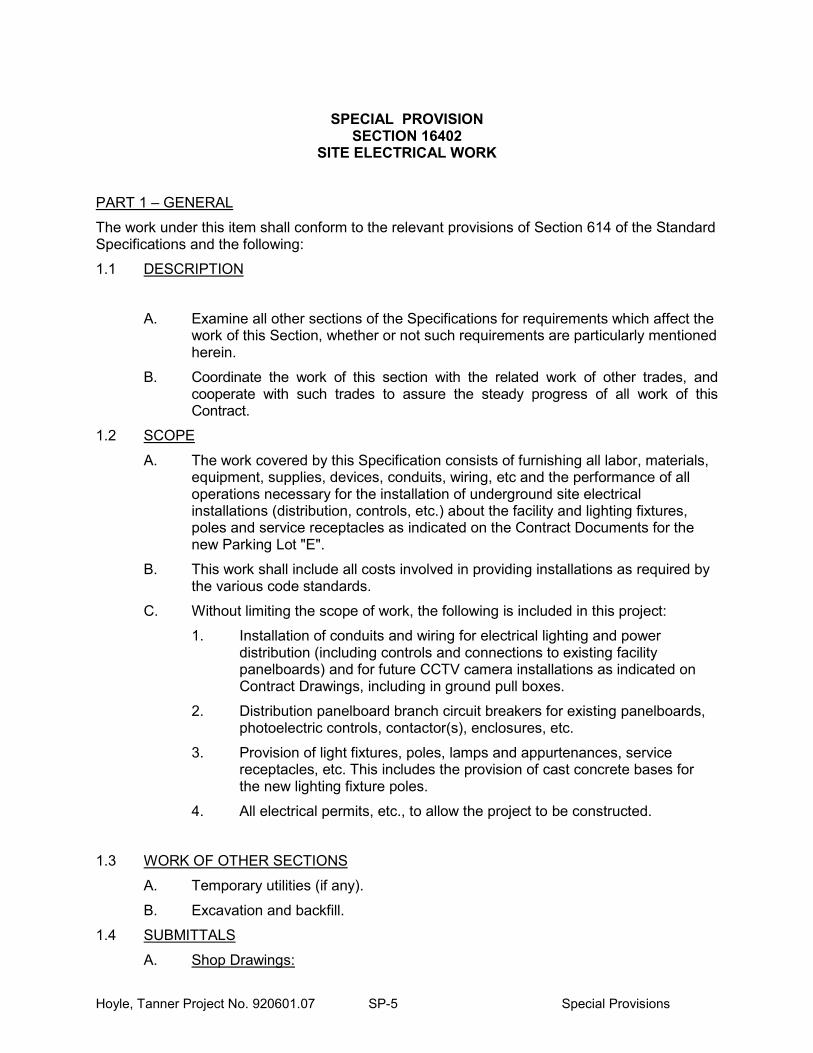
SECTION 16402 SITE ELECTRICAL WORK
PART 1 – GENERAL
The work under this item shall conform to the relevant provisions of Section 614 of the Standard Specifications and the following:
1.1 DESCRIPTION
A. Examine all other sections of the Specifications for requirements which affect the work of this Section, whether or not such requirements are particularly mentioned herein.
B. Coordinate the work of this section with the related work of other trades, and cooperate with such trades to assure the steady progress of all work of this Contract.
1.2 SCOPE
A. The work covered by this Specification consists of furnishing all labor, materials, equipment, supplies, devices, conduits, wiring, etc and the performance of all operations necessary for the installation of underground site electrical installations (distribution, controls, etc.) about the facility and lighting fixtures, poles and service receptacles as indicated on the Contract Documents for the new Parking Lot "E".
B. This work shall include all costs involved in providing installations as required by the various code standards.
C. Without limiting the scope of work, the following is included in this project:
1. Installation of conduits and wiring for electrical lighting and power distribution (including controls and connections to existing facility panelboards) and for future CCTV camera installations as indicated on Contract Drawings, including in ground pull boxes.
2. Distribution panelboard branch circuit breakers for existing panelboards, photoelectric controls, contactor(s), enclosures, etc.
3. Provision of light fixtures, poles, lamps and appurtenances, service receptacles, etc. This includes the provision of cast concrete bases for the new lighting fixture poles.
4. All electrical permits, etc., to allow the project to be constructed.
1.3 WORK OF OTHER SECTIONS
A. Temporary utilities (if any).
B. Excavation and backfill.
1.4 SUBMITTALS
A. Shop Drawings:

Hoyle, Tanner Project No. 920601.07 SP-6 Special Provisions
1. Submit shop drawings in accordance with the requirements of the General Conditions and in the manner described therein. Shop drawings shall indicate specifications section and paragraph requiring equipment indicated.
a. Shop drawings are required on all major pieces of equipment in the following list, but not necessarily limited thereto: conduit, conduit spacers, wire/cable, light fixtures, poles, controls, enclosures, panelboard components, receptacles, etc.
B. Record Drawings:
1. The Subcontractor shall furnish and keep on the job at all times one complete set of black line prints of the electrical work, on which shall be clearly, neatly and accurately noted, promptly as the work progresses, all electrical changes, revisions and additions to the work. Wherever work is installed otherwise than as shown on the Contract Drawings, such changes shall be noted.
2. The Subcontractor shall indicate on these prints the daily progress by coloring in the various apparatus and associated appurtenances as they are installed.
3. No approval of requisition for payment for work installed will be given unless supported by record prints as required above.
C. Operating Instructions and Maintenance Manual:
1. The Subcontractor shall instruct, to the Owner's satisfaction, such persons as the Owner designates in the proper operation and maintenance of systems and their parts.
2. Parties indicated above sign affidavits stating that the above instructions were given by the Electrical Subcontractor.
3. Furnish operating and maintenance manuals and forward same to the Owner’s Representative for transmittal to the Owner.
4. The operating instructions shall be specific for each system and shall include copies of posted specific instructions.
5. For maintenance purposes, provide shop drawings, parts lists, specifications and manufacturer's maintenance bulletins for each piece of equipment. Provide name, address and telephone number of the manufacturer's representative and service company, for each piece of equipment so that service or spare parts can be readily obtained.
D. Manufacturer's Data:
1. Within ten days of award of Contract, the subcontractor shall submit for Engineer's approval a complete list of manufacturer's names of all materials and equipment proposed for the project.
2. After approval of the above list, the Subcontractor shall submit for Engineer's approval complete detailed manufacturer's data consisting of bulletins, shop drawings, and parts lists of the materials and equipment to be furnished, as required.
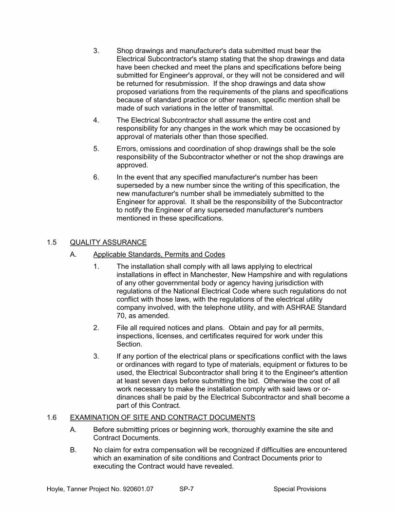
Hoyle, Tanner Project No. 920601.07 SP-7 Special Provisions
3. Shop drawings and manufacturer's data submitted must bear the Electrical Subcontractor's stamp stating that the shop drawings and data have been checked and meet the plans and specifications before being submitted for Engineer's approval, or they will not be considered and will be returned for resubmission. If the shop drawings and data show proposed variations from the requirements of the plans and specifications because of standard practice or other reason, specific mention shall be made of such variations in the letter of transmittal.
4. The Electrical Subcontractor shall assume the entire cost and responsibility for any changes in the work which may be occasioned by approval of materials other than those specified.
5. Errors, omissions and coordination of shop drawings shall be the sole responsibility of the Subcontractor whether or not the shop drawings are approved.
6. In the event that any specified manufacturer's number has been superseded by a new number since the writing of this specification, the new manufacturer's number shall be immediately submitted to the Engineer for approval. It shall be the responsibility of the Subcontractor to notify the Engineer of any superseded manufacturer's numbers mentioned in these specifications.
1.5 QUALITY ASSURANCE
A. Applicable Standards, Permits and Codes
1. The installation shall comply with all laws applying to electrical installations in effect in Manchester, New Hampshire and with regulations of any other governmental body or agency having jurisdiction with regulations of the National Electrical Code where such regulations do not conflict with those laws, with the regulations of the electrical utility company involved, with the telephone utility, and with ASHRAE Standard 70, as amended.
2. File all required notices and plans. Obtain and pay for all permits, inspections, licenses, and certificates required for work under this Section.
3. If any portion of the electrical plans or specifications conflict with the laws or ordinances with regard to type of materials, equipment or fixtures to be used, the Electrical Subcontractor shall bring it to the Engineer's attention at least seven days before submitting the bid. Otherwise the cost of all work necessary to make the installation comply with said laws or or-dinances shall be paid by the Electrical Subcontractor and shall become a part of this Contract.
1.6 EXAMINATION OF SITE AND CONTRACT DOCUMENTS
A. Before submitting prices or beginning work, thoroughly examine the site and Contract Documents.
B. No claim for extra compensation will be recognized if difficulties are encountered which an examination of site conditions and Contract Documents prior to executing the Contract would have revealed.

Hoyle, Tanner Project No. 920601.07 SP-8 Special Provisions
1.7 DRAWINGS
A. The Subcontractor shall refer to the electrical drawings, and other plans and details for a full comprehension of the extent and detail of the work to be per-formed. These drawings are intended to be supplementary to the specifications, and any work indicated, mentioned or implied in either is to be constructed as specified by both.
B. All work shown on the Drawings is intended to be approximately correct to the scale of the drawings, but figured dimensions and detailed drawings are diagrammatic and are not intended to show every detail of construction or the exact location of equipment. Where project construction makes it advisable or necessary to change the location of equipment, the Contractor shall perform such work without cost to the Owner on written request of the Engineer. Any doubt as to the intended location of equipment shall be resolved by the Engineer before proceeding with the installation.
C. The intent is to obtain an electrical installation of all systems, complete in every detail within and about the project site, and with all facilities properly interconnected with power. The Electrical Contractor shall complete the systems in accordance with the best trade practice and to the satisfaction of the Engineer. Upon completion, the electrical systems and all equipment throughout the project shall operate properly and adequately and function as intended.
D. In any discrepancy between requirements of any Section, between notes on the drawings, between drawings, between details in the specifications, or between drawings and specifications, that which is in the best interest of the Owner shall apply.
1. Testing by Contractor: Provide equipment and personnel for operating test of electrical system.
2. Changes by Contractor: The contract drawings indicate the extent and schematic arrangement of the conduit and wiring systems. If changes from the drawings are deemed necessary by the Contractor, submit details of such changes within 30 days of award of Contract. Make no changes without written authorization of Engineer. Where conduit routings are not indicated, coordinate with Engineer, General Contractor, and other Subcontractors to insure no conflicts resulting from routings selected.
1.8 ELECTRICAL REFERENCE SYMBOLS
A. Standard symbols have been employed where such will meet the need. These are augmented and modified to illustrate as necessary. The chart on the Contract Drawings is intended to illustrate all symbols and explain the function and installation method of the device represented. When not clear, or where one has been inadvertently omitted, it shall be the responsibility of the Electrical Contractor to obtain a ruling on the intent before proceeding with any work.
1.9 TEMPORARY POWER
A. If required by any trade, the Electrical Subcontractor shall furnish and install tem-porary service and feeders of proper capacity power required for the site work while under construction. The Electrical Subcontractor shall provide all required transformer(s), panels, etc. Sufficient outlets shall be installed at convenient locations so that extension cords of not over 50 feet will reach all areas requiring
Hoyle, Tanner Project No. 920601.07 SP-9 Special Provisions
power.
B. The General Contractor will pay for the cost of energy consumed by all trades.
C. The General Contractor and all subcontractors shall furnish their own extension cords and such lamps as may be required for their work, and shall pay for the cost of temporary wiring of construction offices or shanties used by them and any temporary wiring of a special nature for light and power required other than that mentioned above.
1.10 GUARANTEE
A. Contractor's guarantee for items furnished covers and includes:
1. Faulty or inadequate design of equipment provided. 2. Improper installation. 3. Defective workmanship and materials.
B. Warranties of Manufacture
1. Not less than one year. 2. As specified. 3. As normally supplied if greater than one year.
1.11 ALTERATIONS
A. The Electrical Subcontractor shall execute all alterations, additions, removals, relocations, or new electrical work, etc., as indicated or required to provide a complete installation in accordance with the intent of the drawings and specifications.
B. Remove any existing equipment to be discontinued as directed by the Owner’s Representative.
C. Existing electrical equipment removed shall remain the property of the Owner and shall be carefully packed and delivered for on site storage at a location designated by the Owner.
D. Any existing work disturbed or damaged by the alterations or new work shall be repaired or replaced to the Owner’s satisfaction.
E. Any existing electrical equipment discontinued and removed and indicated as not wanted for Owner salvage shall be disposed of in a legal and lawful manner by the Electrical Subcontractor.
1.12 SCHEDULING
A. The Subcontractor shall schedule his work in accordance with Contract Requirements relative to any interruption of services and/or the requirements to maintain site areas or spaces available for the Owner's use during construction.
B. If required to maintain operations, work may be required to be scheduled around such limiting conditions. If this occurs this Subcontractor shall provide a suitable work force to accommodate the schedule requirements.
Hoyle, Tanner Project No. 920601.07 SP-10 Special Provisions
PART 2 - PRODUCTS
2.1 GENERAL REQUIREMENTS
A. All materials, devices, and equipment, unless specifically excepted, shall be new.
2.2 IDENTIFICATION
A. All materials shall bear UL labels where such have been established for the particular device.
B. All devices shall show make, type, serial number (where applicable), voltage, amperage, wattage, motor ratings, and all other pertinent data.
C. All wire shall have make, type of insulation, size, and voltage rating clearly marked upon it.
2.3 WIRE AND CABLE
A. All wire and cable shall comply with the latest requirements and specifications of the NFPA and/or the Insulated Power Cable Engineers Association (IPCEA) and shall be as manufactured by Triangle, General Cable, General Electric, Carol, or approved equal, unless otherwise specified or indicated.
B. All conductors used in this wiring system shall be soft-drawn copper wire having a conductivity of not less than 98 percent of that of pure copper, unless otherwise indicated or specified.
C. Wire No. 10 AWG and smaller may be solid and wire No. 8 AWG and larger shall be stranded.
D. All wire and cable shall be stamped approximately every two feet to indicate voltage, type, temperature rating, UL listing, manufacturer’s name, size, etc.
E. All cable and wire shall be: 600-volt; installed in approved raceways or conduit
F. Insulation for cable and wire shall be as follows:
Distribution XHHW-2, THWN-2
G. The following color code shall be used for all conductors. The colors must be fast, fadeless, and capable of withstanding cleaning:
120/208 Volt, 3 phase 277/480 Volt, 3 Phase Phase A (Leg 1) Red Brown Phase B (Leg 2) Black Yellow Phase C (Leg 3) Blue Orange Neutral White Gray Bond Green Green
H. All circuit wires shall be tagged in cabinets, etc., with 1/16” thick tags securely fastened to the connectors with a heavy type of linen wrap at time wires are pulled in and tested. Circuit numbers shall be indicated on the tags. Tags shall not be removed for any reason.
I. Wires and cables shall be carefully handled during installation.
J. When a lubricant is necessary for pulling wires, it must be listed by UL and of such consistency that it will leave no obstruction or tackiness that will prevent pulling out old wires or pulling in new wires or additional wires. No soap flake or vegetable soaps will be permitted.

Hoyle, Tanner Project No. 920601.07 SP-11 Special Provisions
K. Conductors shall be continuous with no splices below grade.
L. All conductors and connections shall be free of grounds, shorts, and opens.
M. Aluminum conductors shall NOT be used on this project.
N. It is the intent of the Engineer that all wiring installed shall be continuous from circuit origin to controls and from controls to and through pull boxes and into the base of the lighting pole it will be utilized at, with splices of conductors that continue to other poles for the same circuit from that pole being made in the base of the pole and no splices being made in the in-ground pull boxes.
2.4 PULLING CABLES
A. All raceways are to be equipped with conductors. Swab all conduit before cable is drawn into them. Any crushed raceways shall be replaced before drawing in cable. Where cable-pulling compounds are required, materials specifically intended for that purpose that may be utilized.
2.5 WIRE CONNECTORS AND DEVICES
A. Provide appropriate devices. Twist on type wire nuts will not be considered acceptable in any wet or damp areas of this project.
B. Each pole shall receive full sized wires into the base and exiting the base to the next pole, with all connections made in the pole base.
2.6 UTILITY SERVICE
A. Electrical utility service is existing and is not modified by this project.
2.7 ELECTRICAL DISTRIBUTION SYSTEM
A. The project consists of the provision of new branch circuit breakers for installation in the Owner's existing distribution panelboards and the wiring from those to the indicated loads on the Contract Drawings.
2.8 PANELBOARDS
A. Panelboards are existing manufactured by General Electric.
B. The existing 120/208 Volt panelboard is Type NLAB with TQB branch breakers. It is mounted adjacent to existing 277/480 volt panel LP4 in the indicated electrical room. It has 2 blank spaces for new breakers for this project.
C. The existing 277/480 Volt designated LP4 with TED branch breakers. There are blank circuit positions available in the panel.
2.9 CONDUITS
A. Exterior below grade.
1. Direct buried conduit and conduit in concrete in earth shall be schedule 40 PVC. All elbows and/or offsets shall be rigid galvanized steel.
2. PVC conduit shall be type II by Carlon Products or approved equal. All plastic joints shall be cemented or heat welded.
3. Provide expansion fittings on all conduits rising from below grade at the exterior of poles and/or other structures and elsewhere as required by codes, ordinances and/or utility standards.

Hoyle, Tanner Project No. 920601.07 SP-12 Special Provisions
4. Provide manufactured PVC or other nonmetallic spacers to maintain uniform separation of all conduits in common trench/ditch installations. Maintain any utility, code and/or ordinance specified separation between conduits for electric power and conduits provided for other purposes.
2.10 JUNCTION AND DEVICE BOXES
A. All boxes shall be held to wood surfaces by wood screws. On metal surface, boxes shall be held by metal-to-metal screws or by machine bolts.
B. Exposed boxes in unfinished areas, where required, shall be coordinated with Owner as to final location and shall be cast metal style with integral threaded hubs and matching plates (Crouse Hinds Types FS or FD). Bell style boxes will not be accepted.
C. Any outside boxes mounted exposed shall be cast metal type with integral threaded hubs, Crouse Hinds Types FS or FD.
D. Pull boxes, cabinet boxes and junction boxes shall be constructed of code gauge galvanized sheet metal of not less than the minimum size recommended by the National Electric Code. Boxes shall be furnished with screw-fastening covers. Where several feeders pass through a common pull box, they shall be tagged to indicate clearly their electrical characteristics, circuit number and panel designation. Where pull boxes must be used in finished areas, the Owner shall be consulted for the location, style of cover, and finish of the box. The location shall always be as inconspicuous as possible. Where shown on the drawings, sizes of pull boxes, terminal and junction boxes shall be followed or next larger standard trade size shall be used. Add pull boxes when such are deemed advantageous.
2.11 RECEPTACLES
A. Ground fault receptacles shall be Class A, NEMA 5-20R configuration. Each device indicated as “GFI” on contract drawings shall be an individually protected device. Receptacles shall listed "weather resistant" type.
B. Outdoor and elsewhere as shown or required to be damp or wet location rated use weatherproof covers, UL listed and identified as "extra duty" and as conforming to NEC Article 406.9(B).
C. Automatic grip set outlets are not permitted.
D. Outlets and plates shall be a product of Bryant, Hubbell, or approved equal.
2.12 CCTV
A. Provide conduit for future CCTV wiring installations as indicated on the Contract Drawings. Provide pull cords on all conduits with attached identification tags on each end to identify the starting and end of each pull cord. Provide in-ground pull boxes for the system as indicated.
B. Conduits shall be provided from the existing electrical room as located on the Contract Drawings to and through underground pull box(es) and to rise in the base of the poles indicated on the Drawings. All cameras, camera brackets, mounting of brackets, wiring, and routing of wiring from within the indicated electrical room to other location(s) within the facility will be by others in the future and all such materials and installations are not a part of the work to be provided under this Project and Contract.

Hoyle, Tanner Project No. 920601.07 SP-13 Special Provisions
2.13 LIGHTING CONTROLS
A. Controls shall consist of a suitably rated photoelectric controller, with appropriate mounting enclosure and shielding as may be required to shield it from adjacent building and/or vehicular traffic lights. This shall be used in conjunction with a time clock installed in the electrical room and approved equal to Paragon 4214-27S, 277 volt, NEMA 1 enclosed controlling power to the associated light fixtures. A contactor, NEMA 1 enclosed, 4 pole, 20 ampere contacts, 277 volt coil, approved equal to Square D Lighting Contactor, Class 8903, Type LG40.
2.14 IN GROUND PULL/SPLICE BOXES
A. Provide all required in ground pull/splice boxes for all electrical power or other uses. Units shall be per Contract Drawings and Quazite boxes by Hubbell, sized per codes, shall be acceptable.
B. Design provides one in ground pull/splice box adjacent to each light pole for electric power. Additional boxes are indicated for future CCTV wiring. Check Contract Drawings for numbers and locations. Units for electric conductors shall have "Electric" or "Power" on their covers. Units for future CCTV conductors shall have “Comm." on their covers.
2.15 CLEAN UP OF SITE
A. At project completion the site is to be cleaned of any and all debris.
B. All accessible abandoned/discontinued wiring, poles, etc. shall be removed.
2.16 DELIVERY, STORAGE AND PROTECTION
A. The Contractor shall be responsible for the work and equipment until finally inspected, tested and accepted. Carefully store materials and equipment which are not immediately installed after delivery to the site. Close open ends of work with temporary covers or plugs during construction to prevent entry of obstructing material.
B. Each Subcontractor shall protect work and material of other trades from damage that might be caused by that Subcontractor’s work or workers and shall make good a damage thus caused.
PART 3 - INSTALLATION
3.1 GENERAL
A. The entire work provided in this specification shall be constructed and finished in every respect in a workmanlike and substantial manner.
B. The Subcontractor shall obtain detailed information from the manufacturer of apparatus as to the proper method of installing and connecting same. The Subcontractor shall also obtain all information from the General Contractor and other Subcontractors that may be necessary to facilitate the work and the completion of the whole project.
C. Before installing any of the work, the Subcontractor shall see that it does not interfere with the clearances required.
D. Work installed by the Subcontractor which interferes with or modifies the design

Hoyle, Tanner Project No. 920601.07 SP-14 Special Provisions
as shown on the Contract Drawings shall be changed as directed by the Engineer, and all costs incidental to such changes shall be paid by the Subcontractor.
E. In any and all cases of discrepancy in figures, plans or specifications the matter shall be immediately submitted to the Engineer for decision.
3.2 SITE VISITS
A. The Subcontractor will be required to visit the site as the work progresses and to carefully investigate the structural and finished conditions affecting all details of the work, and shall arrange such work required to meet such conditions.
3.3 CONDUITS
A. Conduits are to be installed in accordance with details on Contract Drawings and/or any requirements of the utility that will be assigned use of the conduit.
3.4 GROUNDING
A. A copper ground bonding conductor shall be installed in the same conduit as all power wiring. The use of metallic conduit as a bonding conductor is not permitted for installations under this Contract.
3.5 EXPLOSION PROOF REQUIREMENTS
A. Explosion proof areas are not known to exist on the project. If encountered provide appropriate installations per NEC.
3.6 PULLING CABLES
A. Cables shall be installed utilizing pulling equipment designed for the types of wireways or conduits installed. Where lubricating material is required, it shall be a material manufactured for and designed by UL label as suitable for the types of insulation involved on the conductors.
B. Care shall be taken during cable pulling not to cause kinks or sharp bends in the conductors. If insulation on conductors is cut or nicked during pulling, the conductors involved shall be removed and replaced at no added cost to the Owner. During pulling, the maximum strain applied to the conductors shall not exceed 50% of the ultimate strength of the conductors.
3.7 EXAMINATION AND APPROVAL OF WORK
A. No work shall be covered before examination and approval by the Engineer and by all inspectors and authorities having jurisdiction. Replace any imperfect or condemned work with work conforming to requirements and satisfactory to the Engineer, without extra cost to the Owner. If work is covered before due inspection and approval, the Subcontractor shall pay all costs of uncovering and reinstalling the work.
3.8 CLEAN UP AND REPAIR
A. At the completion of the work, the work area shall be left clean. Any damage caused to work of other trades by these installations shall be repaired at the expense of the Subcontractor.
3.9 GUARANTEE
A. Attention is directed to provisions of the General Conditions regarding guarantees and warranties for work under this Contract.

Hoyle, Tanner Project No. 920601.07 SP-15 Special Provisions
B. Manufacturer shall provide standard guarantees for work under this Section. However, such guarantees shall be in addition to and not in lieu of all other liabilities which the manufacturer and Subcontractor may have by law or by other provisions of the Contract Documents.
C. All materials, items of equipment and workmanship furnished under this Section shall carry the standard warranty against all defects in material and workmanship for a period of not less that one (1) year from the date of final acceptance of the work. Any fault due to defective or improper material, equipment, workmanship or design which may develop within that period shall be made good, forthwith by and at the expense of the Subcontractor, including all other damages done to areas, materials and other systems resulting from this failure.
D. This Subcontractor shall guarantee that all elements of the systems are of sufficient capacity to meet the specified performance requirements as are set forth herein or as indicated.
E. Upon receipt of notice from the Owner of failure of any part of the systems or equipment during the guarantee period, the affected part or parts shall be replaced by the Subcontractor.
F. This Subcontractor shall furnish, before the final payment is made, a written guarantee covering the above requirements.
END OF SECTION
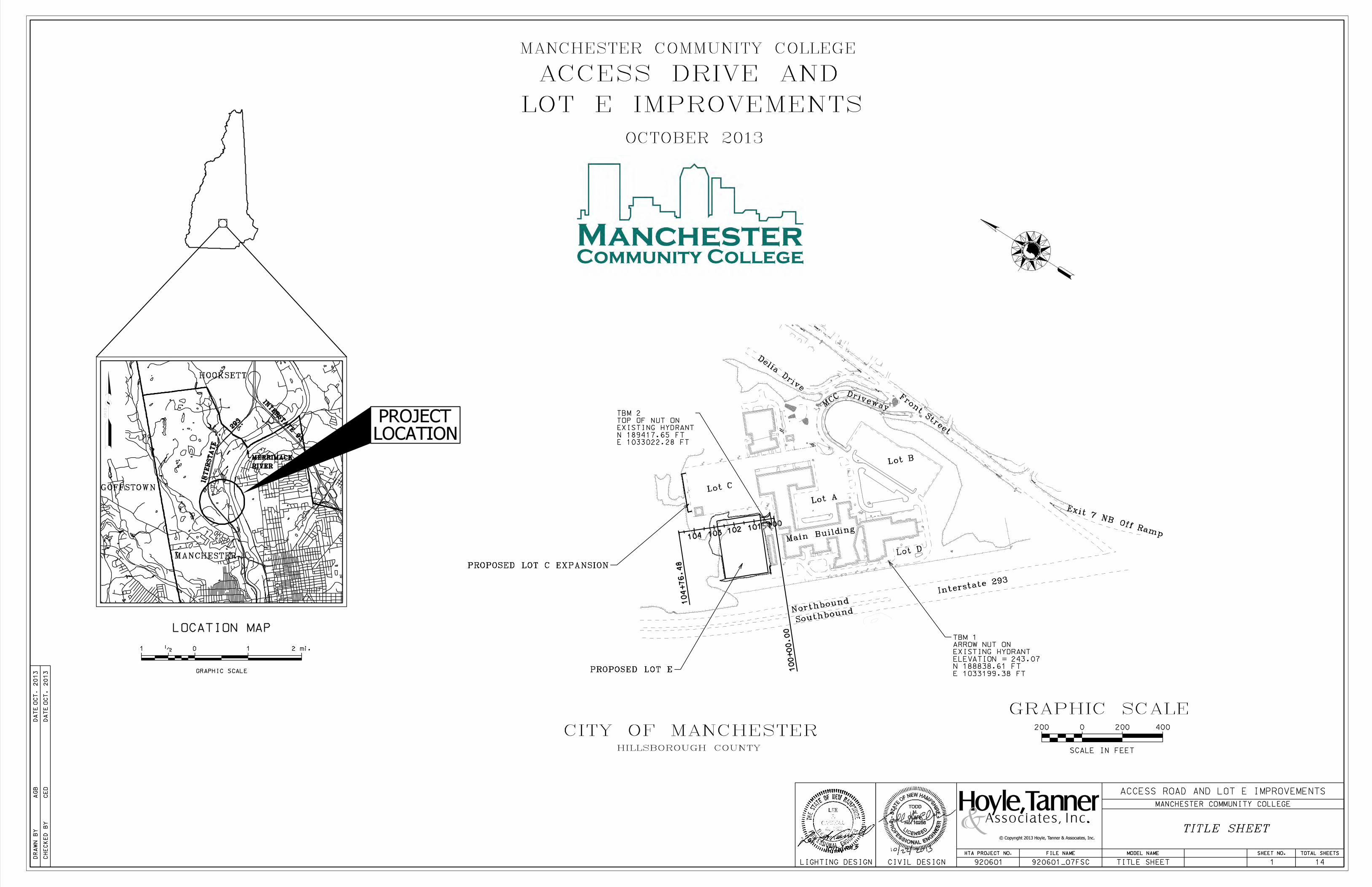
GOFFSTOWN
MANCHESTER
HOOKSETT
MERRIMACK
RIVER
PROPOSED LOT E
TBM 1
ARROW NUT ON
EXISTING HYDRANT
ELEVATION = 243.07
N 188838.61 FT
E 1033199.38 FT
TBM 2
TOP OF NUT ON
EXISTING HYDRANT
N 189417.65 FT
E 1033022.28 FT
PROPOSED LOT C EXPANSION
REVISION DATE
SHEET NO. DESCRIPTION
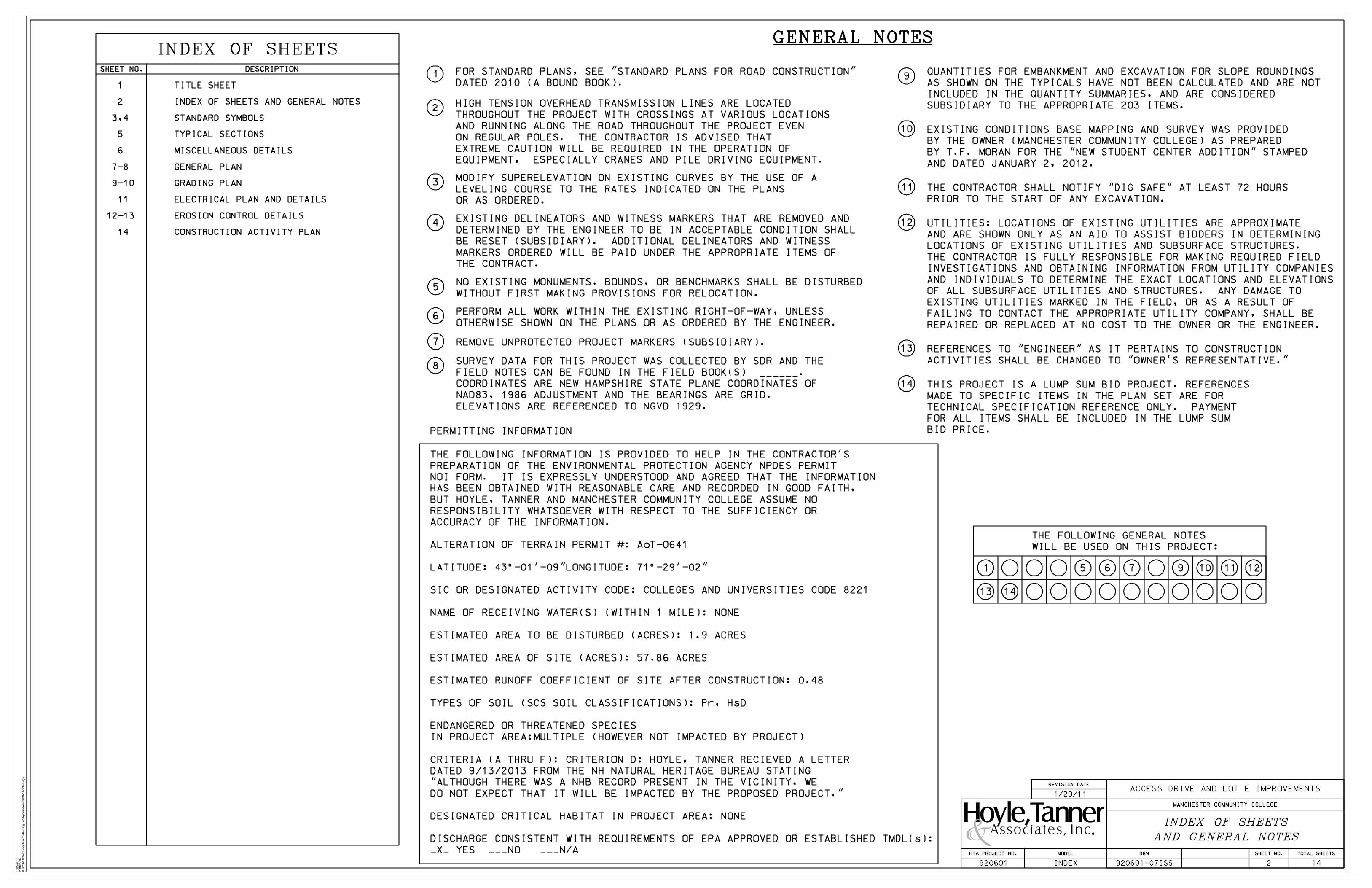
INDEX OF SHEETS
THE FOLLOWING GENERAL NOTES
WILL BE USED ON THIS PROJECT:
1 5 6 7 9
1/20/11
MODIFY SUPERELEVATION ON EXISTING CURVES BY THE USE OF A
LEVELING COURSE TO THE RATES INDICATED ON THE PLANS
OR AS ORDERED.
NO EXISTING MONUMENTS, BOUNDS, OR BENCHMARKS SHALL BE DISTURBED
WITHOUT FIRST MAKING PROVISIONS FOR RELOCATION.
PERFORM ALL WORK WITHIN THE EXISTING RIGHT-OF-WAY, UNLESS
OTHERWISE SHOWN ON THE PLANS OR AS ORDERED BY THE ENGINEER.
REMOVE UNPROTECTED PROJECT MARKERS (SUBSIDIARY).
1
2
3
4
5
6
7
8
GENERAL NOTES
HIGH TENSION OVERHEAD TRANSMISSION LINES ARE LOCATED
THROUGHOUT THE PROJECT WITH CROSSINGS AT VARIOUS LOCATIONS
AND RUNNING ALONG THE ROAD THROUGHOUT THE PROJECT EVEN
ON REGULAR POLES. THE CONTRACTOR IS ADVISED THAT
EXTREME CAUTION WILL BE REQUIRED IN THE OPERATION OF
EQUIPMENT, ESPECIALLY CRANES AND PILE DRIVING EQUIPMENT.
EXISTING DELINEATORS AND WITNESS MARKERS THAT ARE REMOVED AND
DETERMINED BY THE ENGINEER TO BE IN ACCEPTABLE CONDITION SHALL
BE RESET (SUBSIDIARY). ADDITIONAL DELINEATORS AND WITNESS
MARKERS ORDERED WILL BE PAID UNDER THE APPROPRIATE ITEMS OF
THE CONTRACT.
9
SURVEY DATA FOR THIS PROJECT WAS COLLECTED BY SDR AND THE
FIELD NOTES CAN BE FOUND IN THE FIELD BOOK(S) .
COORDINATES ARE NEW HAMPSHIRE STATE PLANE COORDINATES OF
NAD83, 1986 ADJUSTMENT AND THE BEARINGS ARE GRID.
ELEVATIONS ARE REFERENCED TO NGVD 1929.
QUANTITIES FOR EMBANKMENT AND EXCAVATION FOR SLOPE ROUNDINGS
AS SHOWN ON THE TYPICALS HAVE NOT BEEN CALCULATED AND ARE NOT
INCLUDED IN THE QUANTITY SUMMARIES, AND ARE CONSIDERED
SUBSIDIARY TO THE APPROPRIATE 203 ITEMS.
FOR STANDARD PLANS, SEE "STANDARD PLANS FOR ROAD CONSTRUCTION"
DATED 2010 (A BOUND BOOK).
10
10
EXISTING CONDITIONS BASE MAPPING AND SURVEY WAS PROVIDED
BY THE OWNER (MANCHESTER COMMUNITY COLLEGE) AS PREPARED
BY T.F. MORAN FOR THE "NEW STUDENT CENTER ADDITION" STAMPED
AND DATED JANUARY 2, 2012.
11 THE CONTRACTOR SHALL NOTIFY "DIG SAFE" AT LEAST 72 HOURS
PRIOR TO THE START OF ANY EXCAVATION.
12 UTILITIES: LOCATIONS OF EXISTING UTILITIES ARE APPROXIMATE
AND ARE SHOWN ONLY AS AN AID TO ASSIST BIDDERS IN DETERMINING
LOCATIONS OF EXISTING UTILITIES AND SUBSURFACE STRUCTURES.
THE CONTRACTOR IS FULLY RESPONSIBLE FOR MAKING REQUIRED FIELD
INVESTIGATIONS AND OBTAINING INFORMATION FROM UTILITY COMPANIES
AND INDIVIDUALS TO DETERMINE THE EXACT LOCATIONS AND ELEVATIONS
OF ALL SUBSURFACE UTILITIES AND STRUCTURES. ANY DAMAGE TO
EXISTING UTILITIES MARKED IN THE FIELD, OR AS A RESULT OF
FAILING TO CONTACT THE APPROPRIATE UTILITY COMPANY, SHALL BE
REPAIRED OR REPLACED AT NO COST TO THE OWNER OR THE ENGINEER.
11 12
1 TITLE SHEET
2 INDEX OF SHEETS AND GENERAL NOTES
3,4 STANDARD SYMBOLS
5 TYPICAL SECTIONS
6 MISCELLANEOUS DETAILS
7-8 GENERAL PLAN
9-10 GRADING PLAN
11 ELECTRICAL PLAN AND DETAILS
12-13 EROSION CONTROL DETAILS
14 CONSTRUCTION ACTIVITY PLAN
13 REFERENCES TO "ENGINEER" AS IT PERTAINS TO CONSTRUCTION
ACTIVITIES SHALL BE CHANGED TO "OWNER’S REPRESENTATIVE."
14 THIS PROJECT IS A LUMP SUM BID PROJECT. REFERENCES
MADE TO SPECIFIC ITEMS IN THE PLAN SET ARE FOR
TECHNICAL SPECIFICATION REFERENCE ONLY. PAYMENT
FOR ALL ITEMS SHALL BE INCLUDED IN THE LUMP SUM
BID PRICE.
13 14
PERMITTING INFORMATION
THE FOLLOWING INFORMATION IS PROVIDED TO HELP IN THE CONTRACTOR’S
PREPARATION OF THE ENVIRONMENTAL PROTECTION AGENCY NPDES PERMIT
NOI FORM. IT IS EXPRESSLY UNDERSTOOD AND AGREED THAT THE INFORMATION
HAS BEEN OBTAINED WITH REASONABLE CARE AND RECORDED IN GOOD FAITH,
BUT HOYLE, TANNER AND MANCHESTER COMMUNITY COLLEGE ASSUME NO
RESPONSIBILITY WHATSOEVER WITH RESPECT TO THE SUFFICIENCY OR
ACCURACY OF THE INFORMATION.
ALTERATION OF TERRAIN PERMIT #: AoT-0641
LATITUDE: 43%%d-01’-09" LONGITUDE: 71%%d-29’-02"
SIC OR DESIGNATED ACTIVITY CODE: COLLEGES AND UNIVERSITIES CODE 8221
NAME OF RECEIVING WATER(S) (WITHIN 1 MILE): NONE
ESTIMATED AREA TO BE DISTURBED (ACRES): 1.9 ACRES
ESTIMATED AREA OF SITE (ACRES): 57.86 ACRES
ESTIMATED RUNOFF COEFFICIENT OF SITE AFTER CONSTRUCTION: 0.48
TYPES OF SOIL (SCS SOIL CLASSIFICATIONS): Pr, HsD
ENDANGERED OR THREATENED SPECIES
IN PROJECT AREA:MULTIPLE (HOWEVER NOT IMPACTED BY PROJECT)
CRITERIA (A THRU F): CRITERION D: HOYLE, TANNER RECIEVED A LETTER
DATED 9/13/2013 FROM THE NH NATURAL HERITAGE BUREAU STATING
"ALTHOUGH THERE WAS A NHB RECORD PRESENT IN THE VICINITY, WE
DO NOT EXPECT THAT IT WILL BE IMPACTED BY THE PROPOSED PROJECT."
DESIGNATED CRITICAL HABITAT IN PROJECT AREA: NONE
DISCHARGE CONSISTENT WITH REQUIREMENTS OF EPA APPROVED OR ESTABLISHED TMDL(s):
_X_ YES ___NO ___N/ASHEET NO. TOTAL SHEETSDGN
920601-07ISS
HTA PROJECT NO.
920601 2 14INDEX
MODEL
MANCHESTER COMMUNITY COLLEGE
ACCESS DRIVE AND LOT E IMPROVEMENTS

REVISION DATE
SHEET 1 OF 2
w
DRIVEWAYS
BUILDINGS
FOUNDATION
STEPS AND WALK
INTERMITTENT WATER COURSE
SHORE LINE
BRUSH OR WOODS LINE
TREES (PLANS)
HEDGE
WELL
SEPTIC TANK
LEACH FIELD
GAS PUMP
FUEL TANK (ABOVE GROUND)
GRAVE
ROCK OUTCROP
ORIGINAL GROUND
(TYPICALS & SECTIONS ONLY)
(TYPICALS)
ROCK LINE
STONE WALL
RETAINING WALL (LABEL TYPE)
SIGNS
MAILBOX
(label type)
(label type)
river/stream
(deciduous) (coniferous) (stump)
(double post)
(single post)
(label type)
SATELLITE DISH ANTENNA
DELINEATED WETLAND
BORING LOCATION
TEST PIT
CONSTRUCTION BASELINE
PC, PT, POT (ON CONST BASELINE)
PI (IN CONSTRUCTION BASELINES)
INTERSECTION OR EQUATION OF
TWO LINES
ORIGINAL GROUND LINE
(PROFILES AND CROSS-SECTIONS)
PROFILE GRADE LINE
(PROFILES AND CROSS-SECTIONS)
SLOPE LINE (FILL)
SLOPE LINE (CUT)
ORIGINAL GROUND ELEVATION (LEFT)
FINISHED GRADE ELEVATION (RIGHT)
INTERSTATE NUMBERED HIGHWAY
UNITED STATES NUMBERED HIGHWAY
STATE NUMBERED HIGHWAY
PROFILES AND CROSS SECTIONS:
(label surface type)
pond
(label size & type)
FLAG POLE
WETLANDS
ENGINEERING
SLOPE LINE CLEARING LINE
EDGE OF PAVEMENT
TRAVELED WAY
PROPOSED
ROADWAY
existing
roadway
(pavement removed
outside slope lines)
(building to
be removed)
(label house or type
of building)
(label name of
water body)
fp
leach
field
(points toward
retained ground)
s
gp
ft
gr
mb
da
vpVENT PIPE
PHONE
TIDAL BUFFER ZONE
ORDINARY HIGH WATER
HIGHEST OBSERVABLE TIDAL LINE
MEAN HIGH TIDE
SPECIAL AQUATIC SITE
TOP OF BANK
TOP OF BANK & ORDINARY HIGH WATER
VERNAL POOL
INVASIVE SPECIES
CLEARING LINE
SLOPE LINE
GENERAL
ph
STORAGE TANK FILLER CAP
2
PUB2E
OHWOHWOHWOHWOHWOHWVPVPVPVPVPVPVPVPVPVPVPVP
GUARDRAIL (LABEL TYPE)
cgr
bgr
JERSEY BARRIER
fc
B
WATER FRONT BUFFER
NATURAL WOODLAND BUFFER
PROTECTED SHORE LAND
POTENTIAL WET AREA SYMBOL
MONITORING WELL
II
I.S.
I
I.S.INVASIVE SPECIES LABEL
TP
PRIME WETLAND
WETLAND DESIGNATION AND TYPE
293
3
102
BRIDGE CROSSINGS
STREAM OVERPASS
TREE OR STUMP (CROSS-SECTIONS)
(show station, circumference in feet & type)
existing PROPOSED
500 YEAR FLOODPLAIN BOUNDARY
100 YEAR FLOODPLAIN BOUNDARY
FLOODPLAIN / FLOODWAY
FLOODWAY
GROUND LIGHT/LAMP POST gl lp
FENCE (LABEL TYPE)
CURB (LABEL TYPE)
w
mon
MEDIAN CGR
BGR
3/15/13
SHEET NO. TOTAL SHEETSDGN
920601-07ISS
HTA PROJECT NO.
920601 3 14SYM01
MODEL
MANCHESTER COMMUNITY COLLEGE
ACCESS DRIVE AND LOT E IMPROVEMENTS

REVISION DATE
DRAINAGE TRAFFIC SIGNALSUTILITIES
SHEET 2 OF 2
TELEPHONE POLE
POWER POLE
JOINT OCCUPANCY
MISCELLANEOUS/UNKNOWN POLE
POLE STATUS:
AS APPLICABLE e.g.:
LIGHT POLE
LIGHT ON POWER POLE
LIGHT ON JOINT POLE
(plot point at face
not center of symbol)
RIGHT-OF-WAY LINE
PROPERTY LINE
TOWN LINE
COUNTY LINE
STATE LINE
BOUND
DRILL HOLE IN ROCK
NATIONAL FOREST
(label type)
BOW
CONCORD
COOS
GRAFTON
MAINE
IRON PIPE OR PIN
NHDOT PROJECT MARKER
PEDESTAL WITH PEDESTRIAN SIGNAL
HEADS AND PUSH BUTTON UNIT
CONTROLLER CABINET
METER PEDESTAL
PULL BOX
LOOP DETECTOR (QUADRUPOLE)
LOOP DETECTOR (RECTANGULAR)
(label size)
(label size)
PROPERTY PARCEL NUMBER
HISTORIC PROPERTY
WATER SHUT OFF
GAS SHUT OFF
RAILROAD
RAILROAD SIGN
RAILROAD SIGNAL
(label ownership)
HYDRANT
UTILITY JUNCTION BOX
MAST ARM (existing)
OPTICOM RECEIVER
OPTICOM STROBE
MANHOLE
CATCH BASIN
DROP INLET
DRAINAGE PIPE (existing)
EROSION CONTROL/ STONE
SLOPE PROTECTION
(existing)
DRAINAGE
BOUNDARIES / RIGHT-OF-WAY
UTILITIES
di
cb (PROPOSED)
RCP
s
Y
12
DRAINAGE PIPE (PROPOSED)
HEADER (existing & PROPOSED)
REMOVE, LEAVE, PROPOSED, OR TEMPORARYEND SECTION (existing & PROPOSED)
OPEN DITCH (PROPOSED)
SEWER
TELEPHONE
ELECTRICAL
GAS
NEW HAMPSHIRE
S/L T/L
bnd
STATE LINE/
TOWN LINE MONUMENT
show
direction
of flow
(label size
& type)
(label size
& type)
UNDERDRAIN (PROPOSED)
W/ FLUSHING BASIN
MANHOLES
TRAFFIC SIGNAL
LCHIP CONSERVATION EASEMENT
RR RIGHT-OF-WAY LINE
PROPERTY LINE (COMMON OWNER)
TAX MAP AND LOT NUMBER
(with stone outlet
protection)
1642/341
6.80 Ac.¨
156
14
(on existing lines
label size, type and
note if abandoned)
UNDERGROUND UTILITIES
UNDERDRAIN (existing)W/ FLUSHING BASIN
L P+04
25.0’
R T+04
25.0’
jb
M H T
M H E
M H S
M H G
e
g
y
t
s
s
cc
pb
mp
PB
MP
(NOTE ANGLE FROM ¯)
FENCING NOTE
CLEARING AND GRUBBING AREA
DRAINAGE NOTE
GUARDRAIL NOTE
G-1
B-1
LIGHTING NOTE
EROSION CONTROL NOTE
A
1
A
A
1
A
CONSTRUCTION NOTES
(PROPOSED)
GUY POLE OR PUSH BRACE
BENCH MARK / SURVEY DISK
METAL or PLASTIC
CURB MARK NUMBER - GRANITE
CURB MARK NUMBER - BITUMINOUS
fb
TELEPHONE
ELECTRIC
GAS
LIGHTING
FIBER OPTIC
INTELLIGENT TRANSPORTATION SYSTEM
WATER
SEWER
JB
CC
SIGNAL CONDUIT
PROPOSEDexistingPROPOSEDexisting
dh
ip
1TRAFFIC SIGNAL NOTE
OVERHEAD ELECTRIC
uUNKNOWN
d
TRAFFIC SIGNALS / ITS
ITS NOTE
f
ITSitsVS F
FODfod
VARIABLE SPEED LIMIT SIGN
DYNAMIC MESSAGE SIGN
FIBER OPTIC SPLICE VAULT
ROAD AND WEATHER INFO SYSTEM
CAMERA POLE (CCTV)
ITS EQUIPMENT CABINET
1
3/15/13
SHEET NO. TOTAL SHEETSDGN
920601-07ISS
HTA PROJECT NO.
920601 4 14SYM02
MODEL
MANCHESTER COMMUNITY COLLEGE
ACCESS DRIVE AND LOT E IMPROVEMENTS

11’-0" 11’-0" 18’-0"36’-0"22’-0"
29’-0"
23.5"
ITEM 403.11-HOT BITUMINOUS PAVEMENT
MACHINE METHOD, 2.5" NOMINAL
290’-0"
2’-6"
15"
2.5"
6"
ORIGINAL
GROUND
2’-6"
AISLE ENTRANCEEXIT
261’-0"
12’-0" 12’-0"
23.5"
ITEM 403.11-HOT BITUMINOUS PAVEMENT
MACHINE METHOD, 2.5" NOMINAL
2’-6"
15"
2.5"
6"
ORIGINAL
GROUND
2’-6"
ENTRANCEEXIT
24’-0"
ORIGINAL
GROUND
ITEM 609.811 - BITUMINOUS CURB,
TYPE B (4" REVEAL)
ADDITIONAL PARKING
STALLS AND AISLES
(SEE GENERAL PLAN)
3’-0"
1’-0"
1’-0"
2 - 18’-0" LONG X 9’-0" WIDE
PARKING STALLS
18’-0" LONG X 9’-0" WIDE
PARKING STALL
ITEM 641 - LOAM (6")
AND ITEM 646.31 -
TURF ESTABLISHMENT
WITH MULCH AND
TACKIFIERS
ITEM 641 - LOAM (6")
AND ITEM 646.31 -
TURF ESTABLISHMENT
WITH MULCH AND
TACKIFIERS
100 SERIES
CONSTRUCTION
BASELINE
100 SERIES
CONSTRUCTION
BASELINE
ITEM 304.5 - CRUSHED STONE
(COARSE GRADATION) (F)
ITEM 304.4 - CRUSHED STONE
(FINE GRADATION) (F)
ITEM 645.43 - TEMPORARY
SLOPE STABILIZATION TYPE C
ITEM 645.43 - TEMPORARY
SLOPE STABILIZATION TYPE C
19’-0"
23.5"
ITEM 403.11-HOT BITUMINOUS PAVEMENT
MACHINE METHOD, 2.5" NOMINAL
1’-0"
15"
2.5"
6"
19’-0"
LOT E
ENTRANCE/EXIT
STA. 100+15.14 - 100+67.28
NOT TO SCALE
LOT E
STA. 100+67.28 - 102+82.28
NOT TO SCALE
ITEM 304.4 - CRUSHED STONE
(FINE GRADATION) (F)
ITEM 304.5 -
CRUSHED STONE
(COARSE GRADATION)
(F)
ITEM 304.4 - CRUSHED STONE
(FINE GRADATION) (F)
ITEM 304.5 - CRUSHED STONE
(COARSE GRADATION) (F)
ORIGINAL
GROUND
EXISTING
LOT C
PAVEMENT
LOT C EXPANSION
NOT TO SCALE
2.5" BINDER COURSE (0.141 TON/SY)
ITEM 641 - LOAM (6")
AND ITEM 646.31 -
TURF ESTABLISHMENT
WITH MULCH AND
TACKIFIERS
2.5" BINDER COURSE (0.141 TON/SY)
2.5" BINDER COURSE (0.141 TON/SY)
NOTE:
TOPSOIL SHALL BE
REMOVED BENEATH ALL
FILL LOCATIONS.
SHEET NO. TOTAL SHEETSDGN
920601-07TYP00
HTA PROJECT NO.
920601 5 14920601-07TYP01
MODEL
MANCHESTER COMMUNITY COLLEGE
ACCESS DRIVE AND LOT E IMPROVEMENTS
1" PVC ANTI-SIPHON
PIPE ADAPTER
OUTLET PIPE (HIDDEN)
MOUNTING FLANGE
SOLIDS SETTLE
ON BOTTOM
FRONT VIEW SIDE VIEW
REMOVABLE WATERTIGHT
ACCESS PORT,
6" - 10" OPENING
OIL AND DEBRIS
SNOUT OIL-DEBRIS HOOD
ANTI SIPHON DEVICE
CONFIGURATION DETAIL
TYPICAL INSTALLATION
INSTALLATION DETAIL
NOTES
ANCHOR W/ BOLT
(SEE DETAIL A)
FOAM GASKET W/ PSA BACKING
(TRIM TO LENGTH)
MOUNTING FLANGE
INSTALLATION NOTE:
DETAIL B
DETAIL A
DRILLED HOLE ANCHOR SHIELD
STAINLESS BOLT
EXPANSION CONE
(NARROW END OUT)
OUTLET PIPE
D POSITION HOOD SUCH THAT
BOTTOM FLANGE IS A
DISTANCE OF 1/2 OUTLET
PIPE DIAMETER (MIN.)
BELOW THE PIPE INVERT.
MINIMUM DISTANCE FOR PIPES
%%12712" I.D. IS 6".
*NOTE- SUMP DEPTH OF 36" MIN.
FOR %%127OR=12" DIAM. OUTLET. FOR
OUTLETS %%128OR=15", DEPTH = 2.5-3X DIAM.
GASKET COMPRESSED
BETWEEN HOOD AND
STRUCTURE
(SEE DETAIL B)
1/2 D
(1’ MIN.)
1. ALL HOODS SHALL BE CONSTRUCTED OF A GLASS REINFORCED RESIN
COMPOSITE WITH ISO GEL COAT EXTERIOR FINISH WITH A MINIMUM 0.125"
LAMINATE THICKNESS.
2. ALL HOODS SHALL BE EQUIPPED WITH A WATERTIGHT ACCESS PORT, A
MOUNTING FLANGE, AND AN ANTI-SIPHON VENT AS DRAWN. (SEE
CONFIGURATION DETAIL)
3. THE SIZE AND POSITION OF THE HOOD SHALL BE DETERMINED BY OUTLET
PIPE SIZE AS PER MANUFACTURER’S RECOMMENDATION.
4. THE BOTTOM OF THE HOOD SHALL EXTEND DOWNWARD A DISTANCE EQUAL TO
1/2 THE OUTLET PIPE DIAMETER WITH A MINIMUM DISTANCE OF 6" FOR
PIPES %%12712" I.D.
5. THE ANTI-SIPHON VENT SHALL EXTEND ABOVE HOOD BY MINIMUM OF 3"
AND A MAXIMUM OF 24" ACCORDING TO STRUCTURE CONFIGURATION.
6. THE SURFACE OF THE STRUCTURE WHERE THE HOOD IS MOUNTED SHALL BE
FINISHED SMOOTH AND FREE OF LOOSE MATERIAL.
7. THE HOOD SHALL BE SECURELY ATTACHED TO STRUCTURE WALL WITH 3/8 "
STAINLESS STEEL BOLTS AND OIL-RESISTANT GASKET AS SUPPLIED BY
MANUFACTURER. (SEE INSTALLATION DETAIL)
NOT TO SCALE
ITEM 604.0008 OUTLET PIPE HOOD DETAIL
SHEET NO. TOTAL SHEETSDGN
920601-07DTL00
HTA PROJECT NO.
920601 6 14920601-07DTL03
MODEL
MANCHESTER COMMUNITY COLLEGE
ACCESS DRIVE AND LOT E IMPROVEMENTS
PARKING LOT
OVER 6"
ENTRANCE / EXITPARKING LOT
TRANSITION LIP
1"
EDGE OF
N.T.S.
LIP DETAIL
FINISHED GRADE
N.T.S.
DRAINAGE PIPE TRENCH DETAIL
EXISTING
SUBSTRATE
4" MIN.
BACKFILL MATERIAL
(PER STANDARD
SPECIFICATIONS)
2.5" PAVEMENT
TRENCH WIDTH
(PER STANDARD
SPECIFICATIONS)
VARIES
15" CRUSHED STONE (COARSE GRADATION)
6" CRUSHED STONE (FINE GRADATION)
ITEM 585.4 - STONE
FILL, CLASS D
(SUBSID. TO PIPE)DIA.
1
2
34
5
6
7
8
9
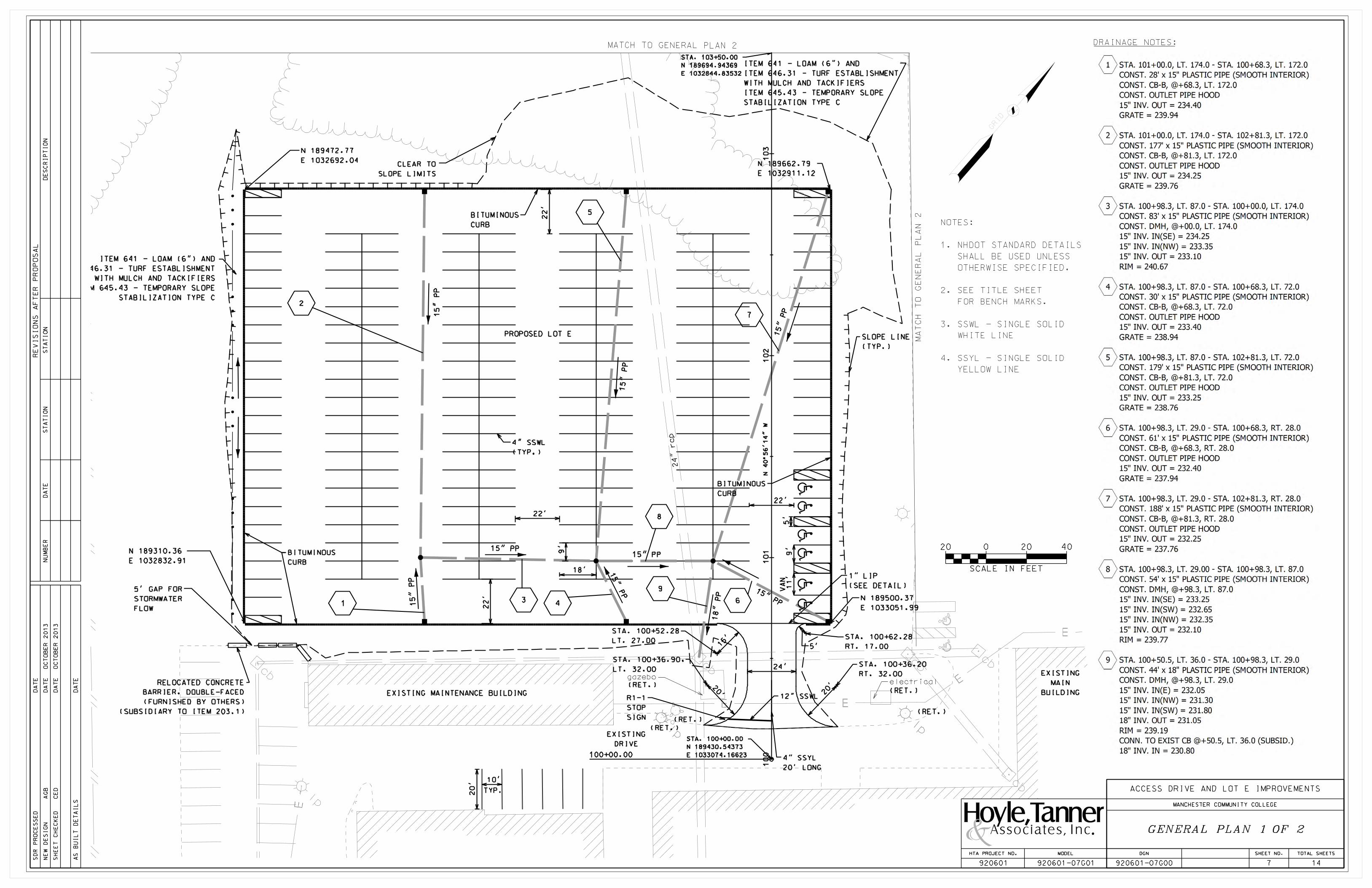
100+00.00
STA. 100+00.00
N 189430.54373
E 1033074.16623
STA. 103+50.00
N 189694.94369
E 1032844.83532
gazebo
24’
22’
22’
EXISTING MAINTENANCE BUILDING
EXISTING
DRIVE
BITUMINOUS
CURB
BITUMINOUS
CURB
BITUMINOUS
CURB
CLEAR TO
SLOPE LIMITS
1" LIP
(SEE DETAIL)5’ GAP FOR
STORMWATER
FLOW
PROPOSED LOT E
EXISTING
MAIN
BUILDINGR1-1
STOP
SIGN(RET.)
electrical
(RET.)
STA. 100+36.90,
LT. 32.00
STA. 100+52.28
LT. 27.00
(RET.)
STA. 100+36.20
RT. 32.00
STA. 100+62.28
RT. 17.00
(RET.)
(RET.)
4" SSYL
20’ LONG
SLOPE LINE
(TYP.)
12" SSWL
4" SSWL
(TYP.)
RELOCATED CONCRETE
BARRIER, DOUBLE-FACED
(FURNISHED BY OTHERS)
(SUBSIDIARY TO ITEM 203.1)
N 189310.36
E 1032832.91
N 189500.37
E 1033051.99
N 189662.79
E 1032911.12
N 189472.77
E 1032692.04
ITEM 641 - LOAM (6") AND
ITEM 646.31 - TURF ESTABLISHMENT
WITH MULCH AND TACKIFIERS
ITEM 645.43 - TEMPORARY SLOPE
STABILIZATION TYPE C
ITEM 641 - LOAM (6") AND
ITEM 646.31 - TURF ESTABLISHMENT
WITH MULCH AND TACKIFIERS
ITEM 645.43 - TEMPORARY SLOPE
STABILIZATION TYPE C
5’
EXISTING SALT
SHED TO BE
RELOCATED
(BY OTHERS)
SHEET NO. TOTAL SHEETSDGN
920601-07G00
HTA PROJECT NO.
920601 7 14920601-07G01
MODEL
MANCHESTER COMMUNITY COLLEGE
ACCESS DRIVE AND LOT E IMPROVEMENTS

5
7
104+76.48
STA. 103+50.00
N 189694.94369
E 1032844.83532
STA. 104+76.48
N 189790.49 FT
E 1032761.96 FT
EXISTING
INFILTRATION
BASIN
EXISTING OUTFALL TO REMAIN
EXISTING
LOT C
BITUMINOUS
CURB
PROPOSED PARKING
LOT EXPANSION
CLEAR TO
SLOPE LIMITS
PROPOSED LOT E
(RET.)
(RET.)(RET.)
(RET.)
SLOPE LINE
(TYP.)
4" SSWL
SLOPE LINE
(TYP.)
N 189662.79
E 1032911.12
N 189472.77
E 1032692.04
ITEM 641 - LOAM (6") AND
ITEM 646.31 - TURF ESTABLISHMENT
WITH MULCH AND TACKIFIERS
ITEM 645.43 - TEMPORARY SLOPE
STABILIZATION TYPE C
5’
27.7’
EXISTING SALT
SHED TO BE
RELOCATED
(BY OTHERS)
LOT C WORK
SHEET NO. TOTAL SHEETSDGN
920601-07G00
HTA PROJECT NO.
920601 8 14920601-07G02
MODEL
MANCHESTER COMMUNITY COLLEGE
ACCESS DRIVE AND LOT E IMPROVEMENTS
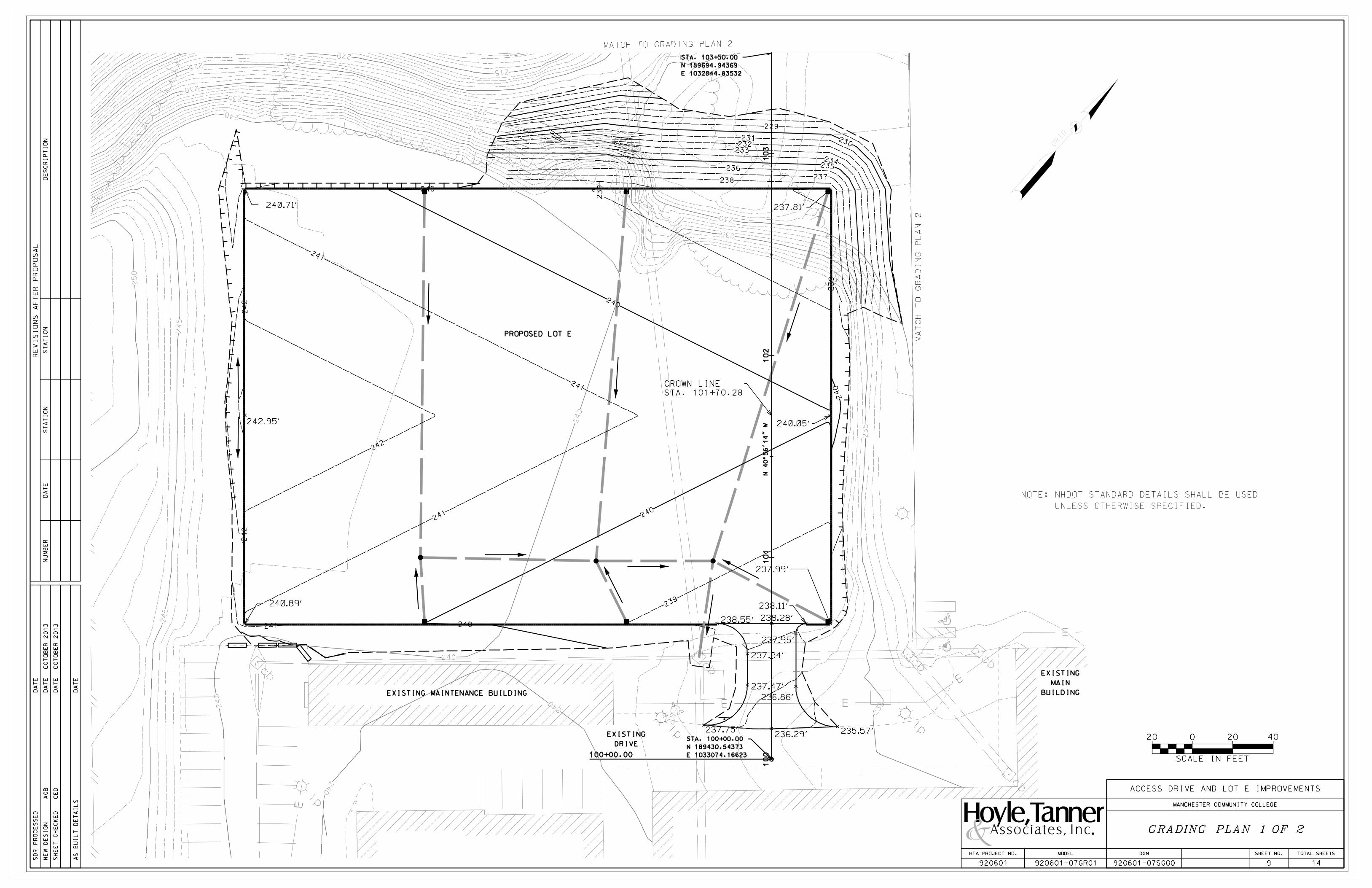
100+00.00
STA. 100+00.00
N 189430.54373
E 1033074.16623
STA. 103+50.00
N 189694.94369
E 1032844.83532
238.55’
242.95’
237.94’
237.47’
237.75’ 235.57’
236.86’
237.95’
238.28’
236.29’
229.58’
229.15’
237.81’
240.05’
237.99’
238.11’
240.71’
240.89’
CROWN LINE
STA. 101+70.28
EXISTING MAINTENANCE BUILDING
EXISTING
DRIVE
PROPOSED LOT E
EXISTING
MAIN
BUILDING
SHEET NO. TOTAL SHEETSDGN
920601-07SG00
HTA PROJECT NO.
920601 9 14920601-07GR01
MODEL
MANCHESTER COMMUNITY COLLEGE
ACCESS DRIVE AND LOT E IMPROVEMENTS

104+76.48
STA. 103+50.00
N 189694.94369
E 1032844.83532
STA. 104+76.48
N 189790.49 FT
E 1032761.96 FT
238.55’
237.94’
237.47’
237.75’ 235.57’
236.86’
237.95’
238.28’
236.29’
229.58’
229.15’ 231.68’
232.86’
237.81’
240.05’
CROWN LINE
STA. 101+70.28
EXISTING
LOT C
PROPOSED PARKING
LOT EXPANSION
PROPOSED LOT E
SHEET NO. TOTAL SHEETSDGN
920601-07SG00
HTA PROJECT NO.
920601 10 14920601-07GR02
MODEL
MANCHESTER COMMUNITY COLLEGE
ACCESS DRIVE AND LOT E IMPROVEMENTS
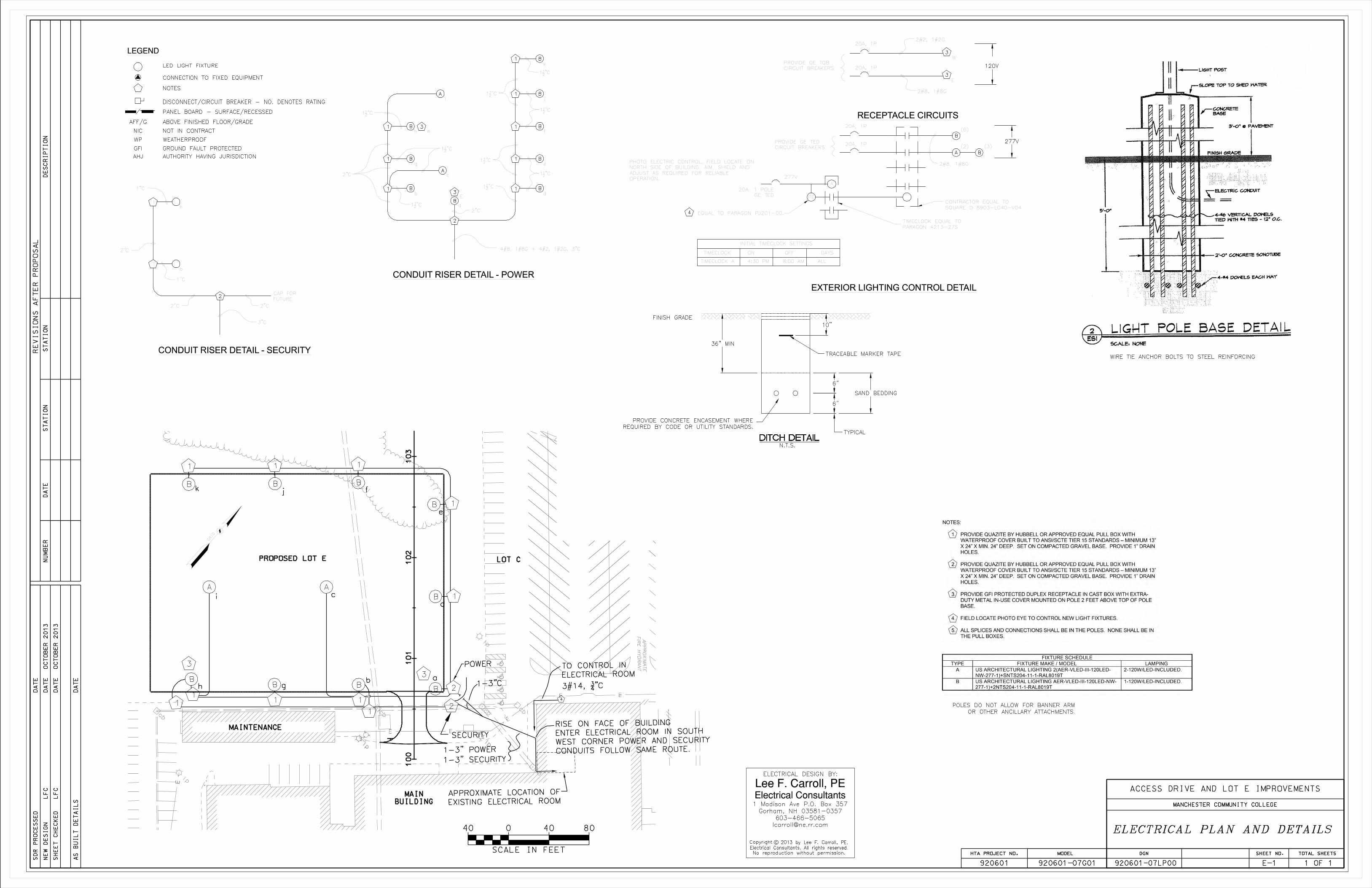
MANCHESTER COMMUNITY COLLEGE
ACCESS DRIVE AND LOT E IMPROVEMENTS
MAINTENANCE
PROPOSED LOT E LOT C
MAIN
BUILDING
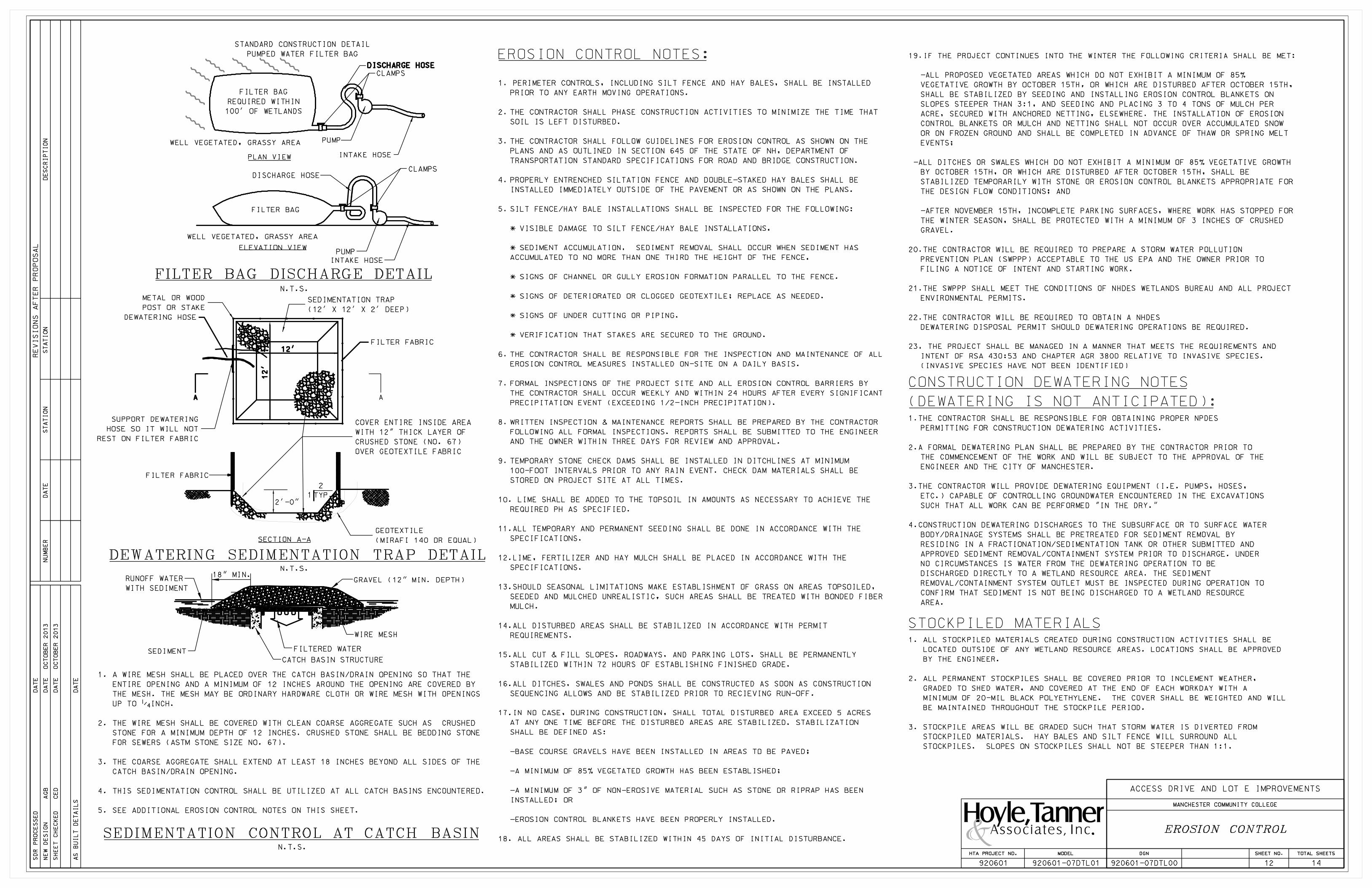
A
12’
A
2’-0"
1 TYP.
2
FILTER FABRIC
N.T.S.18" MIN.
GRAVEL (12" MIN. DEPTH)
FILTERED WATER
CATCH BASIN STRUCTURE
SEDIMENT
N.T.S.
WIRE MESH
N.T.S.
DISCHARGE HOSE
PUMPWELL VEGETATED, GRASSY AREA
INTAKE HOSE
CLAMPS
DISCHARGE HOSE
CLAMPS
INTAKE HOSE
PUMP
DEWATERING SEDIMENTATION TRAP DETAIL
FILTER BAG DISCHARGE DETAIL
EROSION CONTROL NOTES:
STOCKPILED MATERIALS
FILTER BAG
REQUIRED WITHIN
100’ OF WETLANDS
PLAN VIEW
ELEVATION VIEW
WELL VEGETATED, GRASSY AREA
FILTER BAG
FILTER FABRIC
METAL OR WOOD
POST OR STAKE
DEWATERING HOSE
SUPPORT DEWATERING
HOSE SO IT WILL NOT
REST ON FILTER FABRIC
GEOTEXTILE
(MIRAFI 140 OR EQUAL)SECTION A-A
RUNOFF WATER
WITH SEDIMENT
SEDIMENTATION CONTROL AT CATCH BASIN
SEDIMENTATION TRAP
(12’ X 12’ X 2’ DEEP)
STANDARD CONSTRUCTION DETAIL
PUMPED WATER FILTER BAG
COVER ENTIRE INSIDE AREA
WITH 12" THICK LAYER OF
CRUSHED STONE (NO. 67)
OVER GEOTEXTILE FABRIC
1. A WIRE MESH SHALL BE PLACED OVER THE CATCH BASIN/DRAIN OPENING SO THAT THE
ENTIRE OPENING AND A MINIMUM OF 12 INCHES AROUND THE OPENING ARE COVERED BY
THE MESH. THE MESH MAY BE ORDINARY HARDWARE CLOTH OR WIRE MESH WITH OPENINGS
UP TO 1/4 INCH.
2. THE WIRE MESH SHALL BE COVERED WITH CLEAN COARSE AGGREGATE SUCH AS CRUSHED
STONE FOR A MINIMUM DEPTH OF 12 INCHES. CRUSHED STONE SHALL BE BEDDING STONE
FOR SEWERS (ASTM STONE SIZE NO. 67).
3. THE COARSE AGGREGATE SHALL EXTEND AT LEAST 18 INCHES BEYOND ALL SIDES OF THE
CATCH BASIN/DRAIN OPENING.
4. THIS SEDIMENTATION CONTROL SHALL BE UTILIZED AT ALL CATCH BASINS ENCOUNTERED.
5. SEE ADDITIONAL EROSION CONTROL NOTES ON THIS SHEET.
1.THE CONTRACTOR SHALL BE RESPONSIBLE FOR OBTAINING PROPER NPDES
PERMITTING FOR CONSTRUCTION DEWATERING ACTIVITIES.
2.A FORMAL DEWATERING PLAN SHALL BE PREPARED BY THE CONTRACTOR PRIOR TO
THE COMMENCEMENT OF THE WORK AND WILL BE SUBJECT TO THE APPROVAL OF THE
ENGINEER AND THE CITY OF MANCHESTER.
3.THE CONTRACTOR WILL PROVIDE DEWATERING EQUIPMENT (I.E. PUMPS, HOSES,
ETC.) CAPABLE OF CONTROLLING GROUNDWATER ENCOUNTERED IN THE EXCAVATIONS
SUCH THAT ALL WORK CAN BE PERFORMED "IN THE DRY."
4.CONSTRUCTION DEWATERING DISCHARGES TO THE SUBSURFACE OR TO SURFACE WATER
BODY/DRAINAGE SYSTEMS SHALL BE PRETREATED FOR SEDIMENT REMOVAL BY
RESIDING IN A FRACTIONATION/SEDIMENTATION TANK OR OTHER SUBMITTED AND
APPROVED SEDIMENT REMOVAL/CONTAINMENT SYSTEM PRIOR TO DISCHARGE. UNDER
NO CIRCUMSTANCES IS WATER FROM THE DEWATERING OPERATION TO BE
DISCHARGED DIRECTLY TO A WETLAND RESOURCE AREA. THE SEDIMENT
REMOVAL/CONTAINMENT SYSTEM OUTLET MUST BE INSPECTED DURING OPERATION TO
CONFIRM THAT SEDIMENT IS NOT BEING DISCHARGED TO A WETLAND RESOURCE
AREA.
1. PERIMETER CONTROLS, INCLUDING SILT FENCE AND HAY BALES, SHALL BE INSTALLED
PRIOR TO ANY EARTH MOVING OPERATIONS.
2. THE CONTRACTOR SHALL PHASE CONSTRUCTION ACTIVITIES TO MINIMIZE THE TIME THAT
SOIL IS LEFT DISTURBED.
3. THE CONTRACTOR SHALL FOLLOW GUIDELINES FOR EROSION CONTROL AS SHOWN ON THE
PLANS AND AS OUTLINED IN SECTION 645 OF THE STATE OF NH, DEPARTMENT OF
TRANSPORTATION STANDARD SPECIFICATIONS FOR ROAD AND BRIDGE CONSTRUCTION.
4. PROPERLY ENTRENCHED SILTATION FENCE AND DOUBLE-STAKED HAY BALES SHALL BE
INSTALLED IMMEDIATELY OUTSIDE OF THE PAVEMENT OR AS SHOWN ON THE PLANS.
5. SILT FENCE/HAY BALE INSTALLATIONS SHALL BE INSPECTED FOR THE FOLLOWING:
* VISIBLE DAMAGE TO SILT FENCE/HAY BALE INSTALLATIONS.
* SEDIMENT ACCUMULATION. SEDIMENT REMOVAL SHALL OCCUR WHEN SEDIMENT HAS
ACCUMULATED TO NO MORE THAN ONE THIRD THE HEIGHT OF THE FENCE.
* SIGNS OF CHANNEL OR GULLY EROSION FORMATION PARALLEL TO THE FENCE.
* SIGNS OF DETERIORATED OR CLOGGED GEOTEXTILE; REPLACE AS NEEDED.
* SIGNS OF UNDER CUTTING OR PIPING.
* VERIFICATION THAT STAKES ARE SECURED TO THE GROUND.
6. THE CONTRACTOR SHALL BE RESPONSIBLE FOR THE INSPECTION AND MAINTENANCE OF ALL
EROSION CONTROL MEASURES INSTALLED ON-SITE ON A DAILY BASIS.
7. FORMAL INSPECTIONS OF THE PROJECT SITE AND ALL EROSION CONTROL BARRIERS BY
THE CONTRACTOR SHALL OCCUR WEEKLY AND WITHIN 24 HOURS AFTER EVERY SIGNIFICANT
PRECIPITATION EVENT (EXCEEDING 1/2-INCH PRECIPITATION).
8. WRITTEN INSPECTION & MAINTENANCE REPORTS SHALL BE PREPARED BY THE CONTRACTOR
FOLLOWING ALL FORMAL INSPECTIONS. REPORTS SHALL BE SUBMITTED TO THE ENGINEER
AND THE OWNER WITHIN THREE DAYS FOR REVIEW AND APPROVAL.
9. TEMPORARY STONE CHECK DAMS SHALL BE INSTALLED IN DITCHLINES AT MINIMUM
100-FOOT INTERVALS PRIOR TO ANY RAIN EVENT. CHECK DAM MATERIALS SHALL BE
STORED ON PROJECT SITE AT ALL TIMES.
10. LIME SHALL BE ADDED TO THE TOPSOIL IN AMOUNTS AS NECESSARY TO ACHIEVE THE
REQUIRED PH AS SPECIFIED.
11.ALL TEMPORARY AND PERMANENT SEEDING SHALL BE DONE IN ACCORDANCE WITH THE
SPECIFICATIONS.
12.LIME, FERTILIZER AND HAY MULCH SHALL BE PLACED IN ACCORDANCE WITH THE
SPECIFICATIONS.
13.SHOULD SEASONAL LIMITATIONS MAKE ESTABLISHMENT OF GRASS ON AREAS TOPSOILED,
SEEDED AND MULCHED UNREALISTIC, SUCH AREAS SHALL BE TREATED WITH BONDED FIBER
MULCH.
14.ALL DISTURBED AREAS SHALL BE STABILIZED IN ACCORDANCE WITH PERMIT
REQUIREMENTS.
15.ALL CUT & FILL SLOPES, ROADWAYS, AND PARKING LOTS, SHALL BE PERMANENTLY
STABILIZED WITHIN 72 HOURS OF ESTABLISHING FINISHED GRADE.
16.ALL DITCHES, SWALES AND PONDS SHALL BE CONSTRUCTED AS SOON AS CONSTRUCTION
SEQUENCING ALLOWS AND BE STABILIZED PRIOR TO RECIEVING RUN-OFF.
17.IN NO CASE, DURING CONSTRUCTION, SHALL TOTAL DISTURBED AREA EXCEED 5 ACRES
AT ANY ONE TIME BEFORE THE DISTURBED AREAS ARE STABILIZED. STABILIZATION
SHALL BE DEFINED AS:
-BASE COURSE GRAVELS HAVE BEEN INSTALLED IN AREAS TO BE PAVED;
-A MINIMUM OF 85% VEGETATED GROWTH HAS BEEN ESTABLISHED;
-A MINIMUM OF 3" OF NON-EROSIVE MATERIAL SUCH AS STONE OR RIPRAP HAS BEEN
INSTALLED; OR
-EROSION CONTROL BLANKETS HAVE BEEN PROPERLY INSTALLED.
18. ALL AREAS SHALL BE STABILIZED WITHIN 45 DAYS OF INITIAL DISTURBANCE.
19.IF THE PROJECT CONTINUES INTO THE WINTER THE FOLLOWING CRITERIA SHALL BE MET:
-ALL PROPOSED VEGETATED AREAS WHICH DO NOT EXHIBIT A MINIMUM OF 85%
VEGETATIVE GROWTH BY OCTOBER 15TH, OR WHICH ARE DISTURBED AFTER OCTOBER 15TH,
SHALL BE STABILIZED BY SEEDING AND INSTALLING EROSION CONTROL BLANKETS ON
SLOPES STEEPER THAN 3:1, AND SEEDING AND PLACING 3 TO 4 TONS OF MULCH PER
ACRE, SECURED WITH ANCHORED NETTING, ELSEWHERE. THE INSTALLATION OF EROSION
CONTROL BLANKETS OR MULCH AND NETTING SHALL NOT OCCUR OVER ACCUMULATED SNOW
OR ON FROZEN GROUND AND SHALL BE COMPLETED IN ADVANCE OF THAW OR SPRING MELT
EVENTS;
-ALL DITCHES OR SWALES WHICH DO NOT EXHIBIT A MINIMUM OF 85% VEGETATIVE GROWTH
BY OCTOBER 15TH, OR WHICH ARE DISTURBED AFTER OCTOBER 15TH, SHALL BE
STABILIZED TEMPORARILY WITH STONE OR EROSION CONTROL BLANKETS APPROPRIATE FOR
THE DESIGN FLOW CONDITIONS; AND
-AFTER NOVEMBER 15TH, INCOMPLETE PARKING SURFACES, WHERE WORK HAS STOPPED FOR
THE WINTER SEASON, SHALL BE PROTECTED WITH A MINIMUM OF 3 INCHES OF CRUSHED
GRAVEL.
20.THE CONTRACTOR WILL BE REQUIRED TO PREPARE A STORM WATER POLLUTION
PREVENTION PLAN (SWPPP) ACCEPTABLE TO THE US EPA AND THE OWNER PRIOR TO
FILING A NOTICE OF INTENT AND STARTING WORK.
21.THE SWPPP SHALL MEET THE CONDITIONS OF NHDES WETLANDS BUREAU AND ALL PROJECT
ENVIRONMENTAL PERMITS.
22.THE CONTRACTOR WILL BE REQUIRED TO OBTAIN A NHDES
DEWATERING DISPOSAL PERMIT SHOULD DEWATERING OPERATIONS BE REQUIRED.
23. THE PROJECT SHALL BE MANAGED IN A MANNER THAT MEETS THE REQUIREMENTS AND
INTENT OF RSA 430:53 AND CHAPTER AGR 3800 RELATIVE TO INVASIVE SPECIES.
(INVASIVE SPECIES HAVE NOT BEEN IDENTIFIED)
CONSTRUCTION DEWATERING NOTES
(DEWATERING IS NOT ANTICIPATED):
1. ALL STOCKPILED MATERIALS CREATED DURING CONSTRUCTION ACTIVITIES SHALL BE
LOCATED OUTSIDE OF ANY WETLAND RESOURCE AREAS. LOCATIONS SHALL BE APPROVED
BY THE ENGINEER.
2. ALL PERMANENT STOCKPILES SHALL BE COVERED PRIOR TO INCLEMENT WEATHER,
GRADED TO SHED WATER, AND COVERED AT THE END OF EACH WORKDAY WITH A
MINIMUM OF 20-MIL BLACK POLYETHYLENE. THE COVER SHALL BE WEIGHTED AND WILL
BE MAINTAINED THROUGHOUT THE STOCKPILE PERIOD.
3. STOCKPILE AREAS WILL BE GRADED SUCH THAT STORM WATER IS DIVERTED FROM
STOCKPILED MATERIALS. HAY BALES AND SILT FENCE WILL SURROUND ALL
STOCKPILES. SLOPES ON STOCKPILES SHALL NOT BE STEEPER THAN 1:1.
SHEET NO. TOTAL SHEETSDGN
920601-07DTL00
HTA PROJECT NO.
920601 12 14920601-07DTL01
MODEL
MANCHESTER COMMUNITY COLLEGE
ACCESS DRIVE AND LOT E IMPROVEMENTS
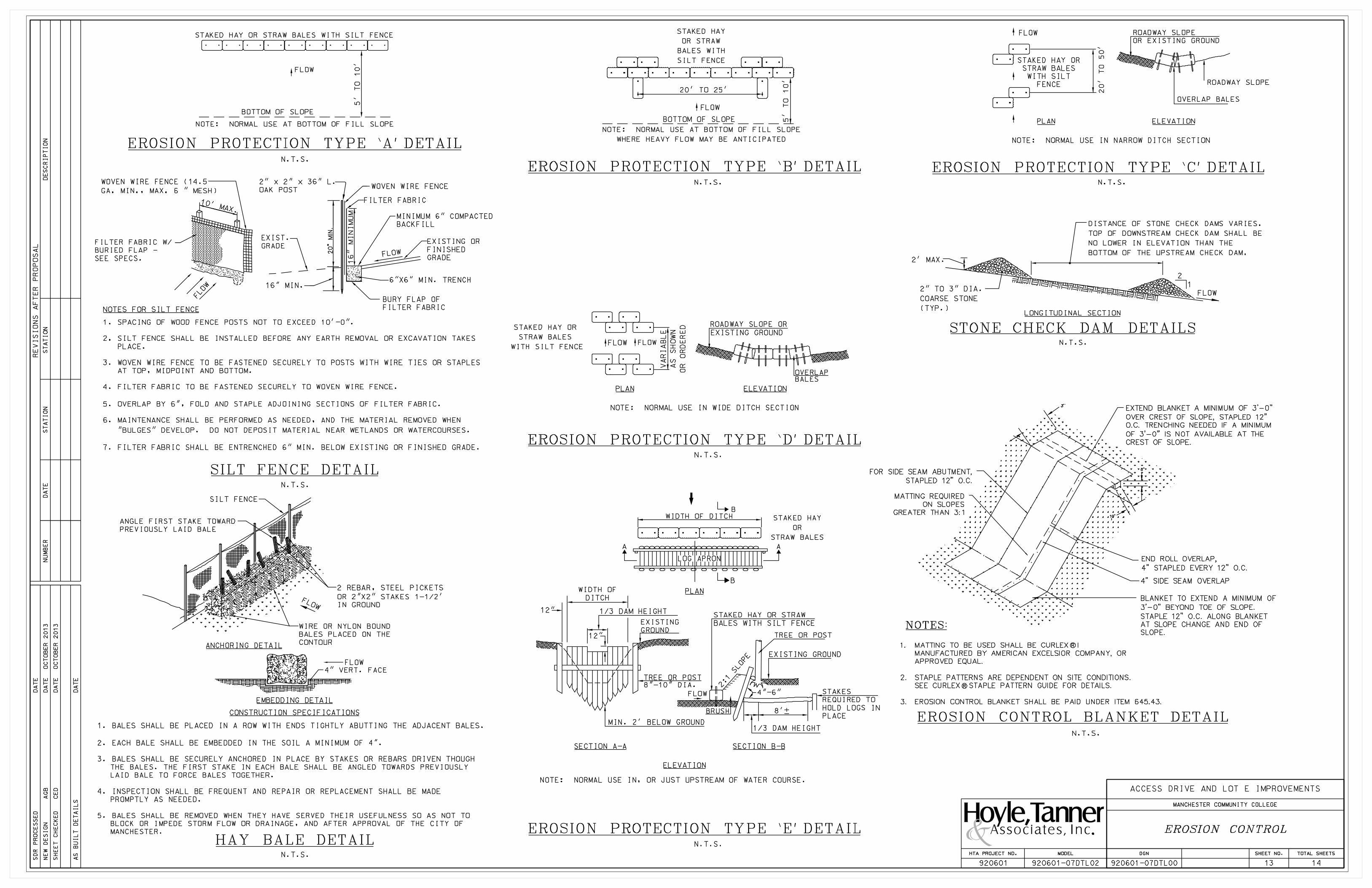
FLOW
1
N.T.S.
2
STONE CHECK DAM DETAILS
LONGITUDINAL SECTION
EMBEDDING DETAIL
N.T.S.
CONSTRUCTION SPECIFICATIONS
SILT FENCE
FILTER FABRIC
WOVEN WIRE FENCE
6"X6" MIN. TRENCH16" MIN.
12"
8’%%p
1/3 DAM HEIGHT
4"-6"
TREE OR POST
EXISTING GROUND
BRUSH
FLOW
1/3 DAM HEIGHT
MIN. 2’ BELOW GROUND
12"
LOG APRON
B
B
WIDTH OF DITCH
N.T.S.
N.T.S.
ELEVATION
BALES
ROADWAY SLOPE OR
EXISTING GROUND
OVERLAP
ROADWAY SLOPE
FLOW
FLOW
NOTE: NORMAL USE IN NARROW DITCH SECTION
OVERLAP BALES
FLOW
NOTE: NORMAL USE IN WIDE DITCH SECTION
N.T.S.
N.T.S.
STAKED HAY OR STRAW BALES WITH SILT FENCE
BOTTOM OF SLOPE
20’ TO 25’
FLOW
NOTE: NORMAL USE AT BOTTOM OF FILL SLOPE
BOTTOM OF SLOPE
N.T.S.
SILT FENCE DETAIL
HAY BALE DETAIL
FLOW
EROSION PROTECTION TYPE ‘A’ DETAIL
MINIMUM 6" COMPACTED
BACKFILL
EXISTING OR
FINISHED
GRADE
BURY FLAP OF
FILTER FABRIC
EXIST.
GRADEFILTER FABRIC W/
BURIED FLAP -
SEE SPECS.
WOVEN WIRE FENCE (14.5
GA. MIN., MAX. 6 " MESH)
2" x 2" x 36" L.
OAK POST
NOTES FOR SILT FENCE
N.T.S.
2 REBAR, STEEL PICKETS
OR 2"X2" STAKES 1-1/2’
IN GROUND
WIRE OR NYLON BOUND
BALES PLACED ON THE
CONTOUR
ANGLE FIRST STAKE TOWARD
PREVIOUSLY LAID BALE
ANCHORING DETAIL
FLOW
4" VERT. FACE
1. SPACING OF WOOD FENCE POSTS NOT TO EXCEED 10’-0".
2. SILT FENCE SHALL BE INSTALLED BEFORE ANY EARTH REMOVAL OR EXCAVATION TAKES
PLACE.
3. WOVEN WIRE FENCE TO BE FASTENED SECURELY TO POSTS WITH WIRE TIES OR STAPLES
AT TOP, MIDPOINT AND BOTTOM.
4. FILTER FABRIC TO BE FASTENED SECURELY TO WOVEN WIRE FENCE.
5. OVERLAP BY 6", FOLD AND STAPLE ADJOINING SECTIONS OF FILTER FABRIC.
6. MAINTENANCE SHALL BE PERFORMED AS NEEDED, AND THE MATERIAL REMOVED WHEN
"BULGES" DEVELOP. DO NOT DEPOSIT MATERIAL NEAR WETLANDS OR WATERCOURSES.
7. FILTER FABRIC SHALL BE ENTRENCHED 6" MIN. BELOW EXISTING OR FINISHED GRADE.
EROSION PROTECTION TYPE ‘C’ DETAILEROSION PROTECTION TYPE ‘B’ DETAIL
EROSION PROTECTION TYPE ‘D’ DETAIL
EROSION PROTECTION TYPE ‘E’ DETAIL
STAKED HAY
OR STRAW
BALES WITH
SILT FENCE
NOTE: NORMAL USE AT BOTTOM OF FILL SLOPE
WHERE HEAVY FLOW MAY BE ANTICIPATED
PLAN
STAKED HAY OR
STRAW BALES
WITH SILT FENCE
STAKED HAY
OR
STRAW BALES
PLAN
AA
SECTION B-BSECTION A-A
ELEVATION
NOTE: NORMAL USE IN, OR JUST UPSTREAM OF WATER COURSE.
STAKED HAY OR STRAW
BALES WITH SILT FENCE
TREE OR POST
8"-10" DIA.
EXISTING
GROUND
WIDTH OF
DITCH
ROADWAY SLOPE
OR EXISTING GROUND
ELEVATIONPLAN
STAKED HAY OR
STRAW BALES
WITH SILT
FENCE
2" TO 3" DIA.
COARSE STONE
(TYP.)
2’ MAX.
DISTANCE OF STONE CHECK DAMS VARIES.
TOP OF DOWNSTREAM CHECK DAM SHALL BE
NO LOWER IN ELEVATION THAN THE
BOTTOM OF THE UPSTREAM CHECK DAM.
EROSION CONTROL BLANKET DETAIL
R
R
8"
’
’3’
NOTES:
MATTING REQUIRED
ON SLOPES
GREATER THAN 3:1
FOR SIDE SEAM ABUTMENT,
STAPLED 12" O.C.
4" SIDE SEAM OVERLAP
END ROLL OVERLAP,
4" STAPLED EVERY 12" O.C.
10"
STAKES
REQUIRED TO
HOLD LOGS IN
PLACE
BLANKET TO EXTEND A MINIMUM OF
3’-0" BEYOND TOE OF SLOPE.
STAPLE 12" O.C. ALONG BLANKET
AT SLOPE CHANGE AND END OF
SLOPE.
EXTEND BLANKET A MINIMUM OF 3’-0"
OVER CREST OF SLOPE, STAPLED 12"
O.C. TRENCHING NEEDED IF A MINIMUM
OF 3’-0" IS NOT AVAILABLE AT THE
CREST OF SLOPE.
N.T.S.
1. BALES SHALL BE PLACED IN A ROW WITH ENDS TIGHTLY ABUTTING THE ADJACENT BALES.
2. EACH BALE SHALL BE EMBEDDED IN THE SOIL A MINIMUM OF 4".
3. BALES SHALL BE SECURELY ANCHORED IN PLACE BY STAKES OR REBARS DRIVEN THOUGH
THE BALES. THE FIRST STAKE IN EACH BALE SHALL BE ANGLED TOWARDS PREVIOUSLY
LAID BALE TO FORCE BALES TOGETHER.
4. INSPECTION SHALL BE FREQUENT AND REPAIR OR REPLACEMENT SHALL BE MADE
PROMPTLY AS NEEDED.
5. BALES SHALL BE REMOVED WHEN THEY HAVE SERVED THEIR USEFULNESS SO AS NOT TO
BLOCK OR IMPEDE STORM FLOW OR DRAINAGE, AND AFTER APPROVAL OF THE CITY OF
MANCHESTER.
1.
MANUFACTURED BY AMERICAN EXCELSIOR COMPANY, OR
APPROVED EQUAL.
2. STAPLE PATTERNS ARE DEPENDENT ON SITE CONDITIONS.
SEE CURLEX STAPLE PATTERN GUIDE FOR DETAILS.
MATTING TO BE USED SHALL BE CURLEX I
3. EROSION CONTROL BLANKET SHALL BE PAID UNDER ITEM 645.43.
SHEET NO. TOTAL SHEETSDGN
920601-07DTL00
HTA PROJECT NO.
920601 13 14920601-07DTL02
MODEL
MANCHESTER COMMUNITY COLLEGE
ACCESS DRIVE AND LOT E IMPROVEMENTS
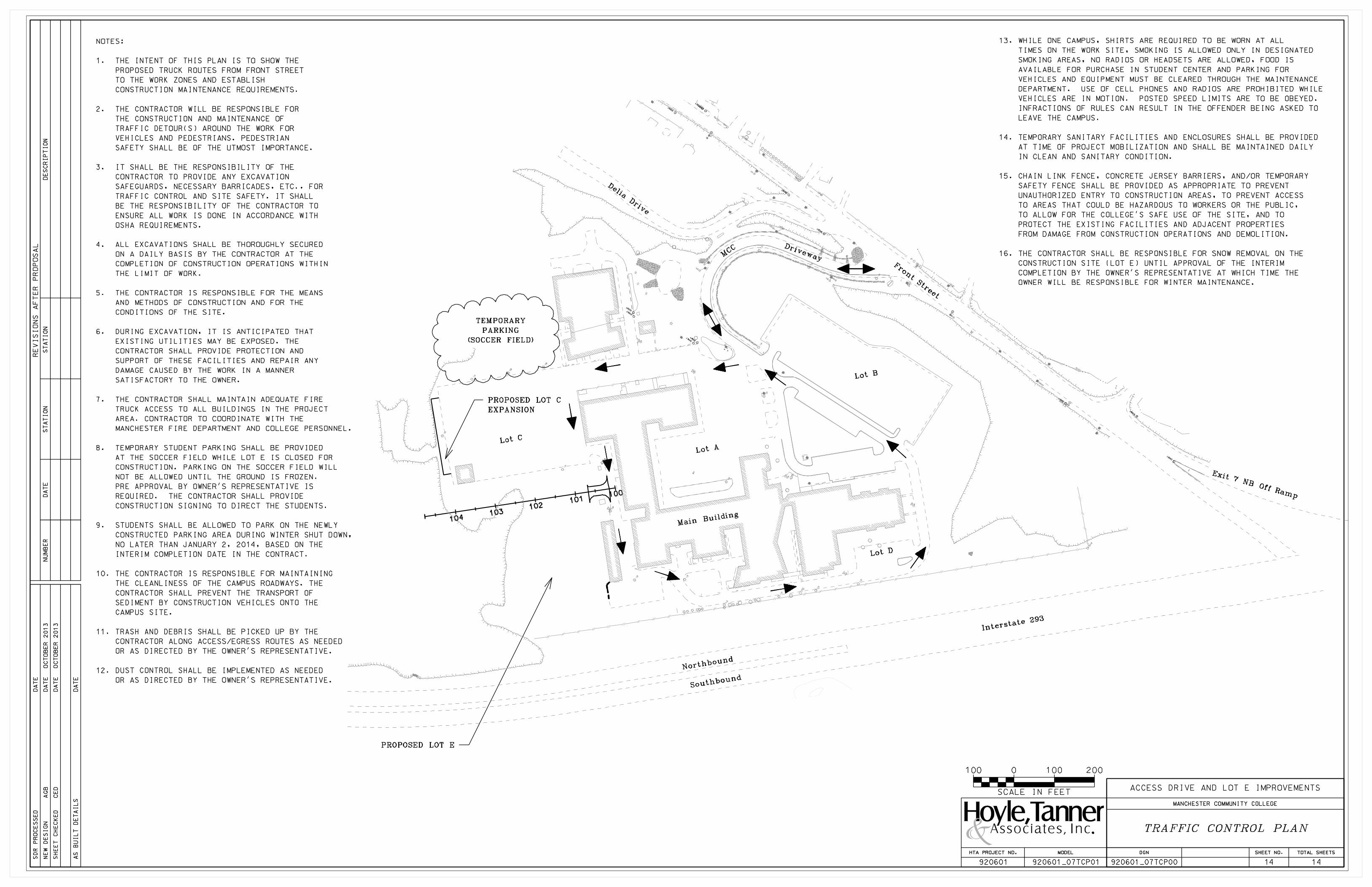
13. WHILE ONE CAMPUS, SHIRTS ARE REQUIRED TO BE WORN AT ALL
TIMES ON THE WORK SITE, SMOKING IS ALLOWED ONLY IN DESIGNATED
SMOKING AREAS, NO RADIOS OR HEADSETS ARE ALLOWED, FOOD IS
AVAILABLE FOR PURCHASE IN STUDENT CENTER AND PARKING FOR
VEHICLES AND EQUIPMENT MUST BE CLEARED THROUGH THE MAINTENANCE
DEPARTMENT. USE OF CELL PHONES AND RADIOS ARE PROHIBITED WHILE
VEHICLES ARE IN MOTION. POSTED SPEED LIMITS ARE TO BE OBEYED.
INFRACTIONS OF RULES CAN RESULT IN THE OFFENDER BEING ASKED TO
LEAVE THE CAMPUS.
14. TEMPORARY SANITARY FACILITIES AND ENCLOSURES SHALL BE PROVIDED
AT TIME OF PROJECT MOBILIZATION AND SHALL BE MAINTAINED DAILY
IN CLEAN AND SANITARY CONDITION.
15. CHAIN LINK FENCE, CONCRETE JERSEY BARRIERS, AND/OR TEMPORARY
SAFETY FENCE SHALL BE PROVIDED AS APPROPRIATE TO PREVENT
UNAUTHORIZED ENTRY TO CONSTRUCTION AREAS, TO PREVENT ACCESS
TO AREAS THAT COULD BE HAZARDOUS TO WORKERS OR THE PUBLIC,
TO ALLOW FOR THE COLLEGE’S SAFE USE OF THE SITE, AND TO
PROTECT THE EXISTING FACILITIES AND ADJACENT PROPERTIES
FROM DAMAGE FROM CONSTRUCTION OPERATIONS AND DEMOLITION.
16. THE CONTRACTOR SHALL BE RESPONSIBLE FOR SNOW REMOVAL ON THE
CONSTRUCTION SITE (LOT E) UNTIL APPROVAL OF THE INTERIM
COMPLETION BY THE OWNER’S REPRESENTATIVE AT WHICH TIME THE
OWNER WILL BE RESPONSIBLE FOR WINTER MAINTENANCE.
NOTES:
1. THE INTENT OF THIS PLAN IS TO SHOW THE
PROPOSED TRUCK ROUTES FROM FRONT STREET
TO THE WORK ZONES AND ESTABLISH
CONSTRUCTION MAINTENANCE REQUIREMENTS.
2. THE CONTRACTOR WILL BE RESPONSIBLE FOR
THE CONSTRUCTION AND MAINTENANCE OF
TRAFFIC DETOUR(S) AROUND THE WORK FOR
VEHICLES AND PEDESTRIANS. PEDESTRIAN
SAFETY SHALL BE OF THE UTMOST IMPORTANCE.
3. IT SHALL BE THE RESPONSIBILITY OF THE
CONTRACTOR TO PROVIDE ANY EXCAVATION
SAFEGUARDS, NECESSARY BARRICADES, ETC., FOR
TRAFFIC CONTROL AND SITE SAFETY. IT SHALL
BE THE RESPONSIBILITY OF THE CONTRACTOR TO
ENSURE ALL WORK IS DONE IN ACCORDANCE WITH
OSHA REQUIREMENTS.
4. ALL EXCAVATIONS SHALL BE THOROUGHLY SECURED
ON A DAILY BASIS BY THE CONTRACTOR AT THE
COMPLETION OF CONSTRUCTION OPERATIONS WITHIN
THE LIMIT OF WORK.
5. THE CONTRACTOR IS RESPONSIBLE FOR THE MEANS
AND METHODS OF CONSTRUCTION AND FOR THE
CONDITIONS OF THE SITE.
6. DURING EXCAVATION, IT IS ANTICIPATED THAT
EXISTING UTILITIES MAY BE EXPOSED. THE
CONTRACTOR SHALL PROVIDE PROTECTION AND
SUPPORT OF THESE FACILITIES AND REPAIR ANY
DAMAGE CAUSED BY THE WORK IN A MANNER
SATISFACTORY TO THE OWNER.
7. THE CONTRACTOR SHALL MAINTAIN ADEQUATE FIRE
TRUCK ACCESS TO ALL BUILDINGS IN THE PROJECT
AREA. CONTRACTOR TO COORDINATE WITH THE
MANCHESTER FIRE DEPARTMENT AND COLLEGE PERSONNEL.
8. TEMPORARY STUDENT PARKING SHALL BE PROVIDED
AT THE SOCCER FIELD WHILE LOT E IS CLOSED FOR
CONSTRUCTION. PARKING ON THE SOCCER FIELD WILL
NOT BE ALLOWED UNTIL THE GROUND IS FROZEN.
PRE APPROVAL BY OWNER’S REPRESENTATIVE IS
REQUIRED. THE CONTRACTOR SHALL PROVIDE
CONSTRUCTION SIGNING TO DIRECT THE STUDENTS.
9. STUDENTS SHALL BE ALLOWED TO PARK ON THE NEWLY
CONSTRUCTED PARKING AREA DURING WINTER SHUT DOWN,
NO LATER THAN JANUARY 2, 2014, BASED ON THE
INTERIM COMPLETION DATE IN THE CONTRACT.
10. THE CONTRACTOR IS RESPONSIBLE FOR MAINTAINING
THE CLEANLINESS OF THE CAMPUS ROADWAYS. THE
CONTRACTOR SHALL PREVENT THE TRANSPORT OF
SEDIMENT BY CONSTRUCTION VEHICLES ONTO THE
CAMPUS SITE.
11. TRASH AND DEBRIS SHALL BE PICKED UP BY THE
CONTRACTOR ALONG ACCESS/EGRESS ROUTES AS NEEDED
OR AS DIRECTED BY THE OWNER’S REPRESENTATIVE.
12. DUST CONTROL SHALL BE IMPLEMENTED AS NEEDED
OR AS DIRECTED BY THE OWNER’S REPRESENTATIVE.
PROPOSED LOT E
PROPOSED LOT C
EXPANSION
TEMPORARY
PARKING
(SOCCER FIELD)