computer organization ch 1(mu)
63
Chapter 1:Introduction 1 Chapter 1 Introduction Computer Organization and Architecture
description
COA asper (MU)
Transcript of computer organization ch 1(mu)

Chapter 1:Introduction 1
Chapter 1 Introduction
Computer Organization and Architecture

Chapter 1:Introduction 2
• Computer Organization
– Refers to the operational units and their interconnection that realize the architecture specification.
– Organization attributes include those hardware details transparent to the programmer
• Control signals
• Interfaces between Computer and peripherals
• Memory technology
Organization

Chapter 1:Introduction 3
• Computer Organization
– Refers to the operational units and their interconnection that realize the architecture specification.
– Organization attributes include those hardware details transparent to the programmer
• Control signals
• Interfaces between Computer and peripherals
• Memory technology
Organization

Chapter 1:Introduction 4
• Computer Architecture
– Computer architecture refers to those attributes of a system visible to a programmer
– Those attributes that have a direct impact on the logical execution of a program.
• Instruction sets• Instruction formats,• Data types,• Addressing modes.
Architecture

Human Computation vs ComputerInput-Output Equipment
Central Processing Unit
Main Memory

Chapter 1:Introduction 6
Computer Components
• At the most basic level, a computer is a device consisting of three pieces:
– A processor to interpret and execute programs
– A memory to store both data and programs
– A mechanism for transferring data to and from the outside world.
Functional Units
Figure 1.1. Basic functional units of a computer.
I/O Processor
Output
Memory
Input andArithmetic
logic
Control

Information Handled by a Computer
• Instructions/machine instructions Govern the transfer of information within a computer as
well as between the computer and its I/O devices Specify the arithmetic and logic operations to be
performed Program• Data Used as operands by the instructions
• Encoded in binary code – 0 and 1

Memory Unit
• Store programs and data• Two classes of storage Primary storage Fast Programs must be stored in memory while they are being executed Large number of semiconductor storage cells Processed in words Address RAM and memory access time Memory hierarchy – cache, main memory
Secondary storage – larger and cheaper

Arithmetic and Logic Unit (ALU)
• Most computer operations are executed in ALU of the processor.
• Load the operands into memory – bring them to the processor – perform operation in ALU – store the result back to memory or retain in the processor.
• Registers

Control Unit• All computer operations are controlled by the control unit.
• The timing signals that govern the I/O transfers are also generated by the control unit
• Control unit is usually distributed throughout the machine instead of standing alone.
• Operations of a computer:– Accept information in the form of programs and data through an
input unit and store it in the memory– Fetch the information stored in the memory, under program
control, into an ALU, where the information is processed– Output the processed information through an output unit– Control all activities inside the machine through a control unit

Chapter 1:Introduction 12
0th Generation ComputersEarly mechanicalcomputational devices
Abacus
Pascal’sCalculator(1600s)
Babbage’sAnalytical Engine(1832)
Difference Engine

Chapter 1:Introduction 13
Abacus
The abacus, a simple counting aid, may have been invented in Babylonia (now Iraq) in the fourth century B.C.
This device allows users to make computations using a system of sliding beads arranged on a rack.

In 1642, the French mathematician and philosopher Blaise Pascal invented a calculating device that would come to be called the "Adding Machine".
Blaise Pascal

Blaise Pascal
Originally called a "numerical wheel calculator" or the "Pascaline", Pascal's invention utilized a train of 8 moveable dials to add sums of up to 8 figures long.
Pascal's mechanical Adding Machine automated the process of calculation. Although slow by modern standards, this machine did provide a fair degree of accuracy and speed.

Charles Babbage
• 19th Centuary
• English inventor
Taught math at Cambridge University
• Invented a viable mechanical computer equivalent to modern digital computers

Babbage’s first computer
Built in early 1800’s
Special purpose calculator
Perform multi-step operations automatically
Compute & print mathematical tables automatically
Perform only addition
Calculates complex function
Used for solving the polynomial and trigonometric functions.
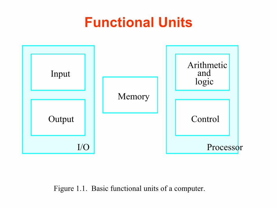
Babbage’s second computer It was first described in 1837 as the
successor to Babbage's Difference engine
The Analytical Engine incorporated
An arithmetic logic unit,
Control flow in the form of conditional branching and loops,
Integrated memory,
The first design for a general-purpose computer
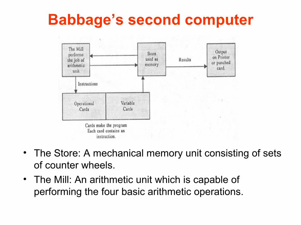
Babbage’s second computer
• The Store: A mechanical memory unit consisting of sets of counter wheels.
• The Mill: An arithmetic unit which is capable of performing the four basic arithmetic operations.

Babbage’s second computer
(a) Operation Cards: Selects one of four arithmetic operating by activating the mill to perform the selected function.
(b) Variable Cards: Selects the memory locations to be used by the mill for a particular operation (i.e. the source of the operands and the destination of the results).
Output: Could be directed to a printer or a card punch device.

Chapter 1:Introduction 21
0th Generation ComputersEarly mechanicalcomputational devices
Computing speed is limited
- Inertia of moving parts
Transmission of digital
information is quite
unreliable

Chapter 1:Introduction 22
1st Generation Computers Moving parts Transmitted & processed
at speed approaching Speed of light(300,000km/s)
Vaccum tubes Developed in 1900s
Processes & stores digital signals
Programmed in machine language
Often programmed by physical connection(hardwiring)

Chapter 1:Introduction 23
1st Generation ComputersThe ENIAC ( Electronic Numerical Integrator and Calculator)
The first programmable electronic computer – 1946
Enormous machine- 18000 vacuum tubes, 1800 square feet, 30 tons
Accumulator : Set of electronic memory units
Capacity : Twenty 10 digits decimal numbers
Operations : Addition, subtraction, Division, multiplication & Square root extraction
Store Program Concept- Von Neumann
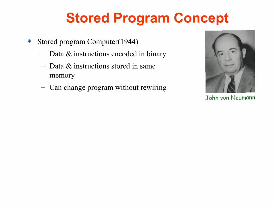
Stored Program Concept
Stored program Computer(1944)
– Data & instructions encoded in binary
– Data & instructions stored in same memory
– Can change program without rewiring

Chapter 1:Introduction 25
1st Generation Computers
The EDVAC( Electronic Discrete Variable Computer)-1951
Binary serial computer with automatic addition, subtraction, multiplication, division and automatic checking
Two kinds memory
Main Memory: Capacity of 1024 words or 1K Words
– Secondary Memory: Capacity of 20K words
Capacity of 1,000 44-bit words

Chapter 1:Introduction 26
Organization of 1st Generation Computers
Instructions
Data
Programs,Data, Operator Command

Organization of IAS Computers
Instruction Unit I-unit
Fetching & Interpreting
Instructions
Execution Unit E-unit
Executing
Instructions

28282828
IAS Computer Machine LanguageIAS Computer Machine Language
40-bit word, two machine instructions per word.
Left instruction Right instruction
bit 0 7 8 19 20 27 28 39
8-bit opcode 12-bit memory address
(operand)
Memory Capacity
212 = 4K * 40( bit words)

29292929
IAS Data Transfer Instructions IAS Data Transfer Instructions
InstructionInstruction Opcode Description Opcode DescriptionLOAD MQ 00001010 AC ← MQLOAD MQ, M(X) 00001001 MQ ← M(X)STOR M(X) 00100001 M(X) ← ACLOAD M(X) 00000001 AC ← M(X)
Instruction format: Op A

30303030
IAS Arithmetic Instructions IAS Arithmetic Instructions
Instruction Opcode Instruction Opcode DescriptionDescription
ADD M(X) 00000101 AC ← AC + M(X)
SUB M(X) 00000110 AC ← AC ─ M(X)
MUL M(X) 00001011 AC, MQ ← MQ×M(X)
DIV M(X) 00001100 MQ, AC ← MQ/M(X)

3131Spring 2013, Jan 16 . . .Spring 2013, Jan 16 . . . ELEC 5200-001/6200-001 Lecture 2ELEC 5200-001/6200-001 Lecture 2 3131
How IAS Computer Adds Two NumbersHow IAS Computer Adds Two Numbers
Suppose the numbers are stored in memory locations 100 and 101, and
The sum is to be saved in memory location 102
Instruction Opcode Description
LOAD M(100) 00000001 AC ← M(100)
ADD M(101) 00000101 AC ← AC + M(101)
STOR M(102) 00100001 M(102) ← AC

32323232
IAS Computer Machine LanguageIAS Computer Machine Language
40-bit word, two machine instructions per word.
Left instruction Right instruction
bit 0 7 8 19 20 27 28 39
8-bit opcode 12-bit memory address
(operand)
Memory Capacity
212 = 4K * 40( bit words)

3333Spring 2013, Jan 16 . . .Spring 2013, Jan 16 . . . ELEC 5200-001/6200-001 Lecture 2ELEC 5200-001/6200-001 Lecture 2 3333
IAS Computer Machine CodeIAS Computer Machine Code
00000001 000001100100 00000101 000001100101
00100001 000001100110 00000000 000000000000
Load 100 Add 101
Stor 102 Stop

3434Spring 2013, Jan 16 . . .Spring 2013, Jan 16 . . . ELEC 5200-001/6200-001 Lecture 2ELEC 5200-001/6200-001 Lecture 2 3434
Review : First-Generation Review : First-Generation ComputersComputers
Late 1940s and 1950sLate 1940s and 1950s
Stored-program computersStored-program computers
Programmed in assembly language: Example ADD A,BProgrammed in assembly language: Example ADD A,B
Used magnetic devices and earlier forms of memoriesUsed magnetic devices and earlier forms of memories
Examples: IAS, ENIAC, EDVAC, UNIVAC, Mark I, IBM Examples: IAS, ENIAC, EDVAC, UNIVAC, Mark I, IBM 701701

Chapter 1:Introduction 35
2nd Generation Computers• Transistors replaced vacuum tubes
– High speed electronic switch for binary signal– Smaller– Requires less power– Cheaper
• Primary memory – Ferrite core memory
• Secondary memory– Magnetic Disks
• Various programming languages introduced – High-level – FORTRAN (Formula Translation)– COBOL ( Common Business Oriented
Language)• IBM 7094
– IOP processor
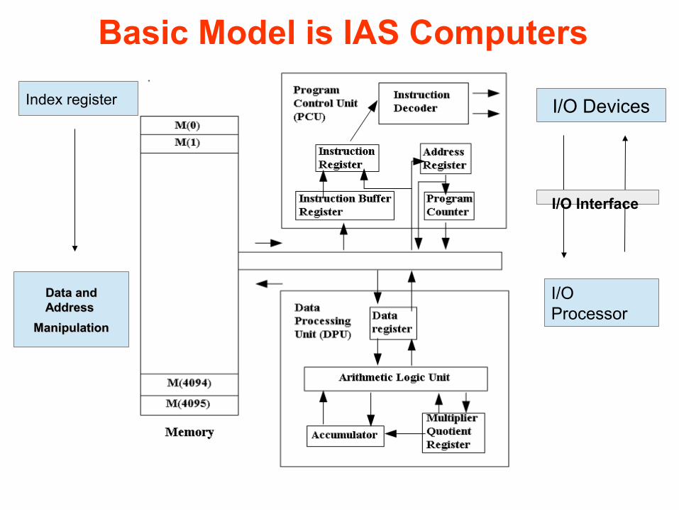
Basic Model is IAS Computers
Index register
Data and Data and Address Address
ManipulationManipulation
I/O Devices
I/O Processor
I/O Interface

Chapter 1:Introduction 37
3rd Generation Computers• Integrated circuit (IC) – or the ability to place
transistor & associated components onto silicon chips– Result was easily mass-produced components
reducing the cost of computer manufacturing significantly
• Smaller size• Higher Speed• Concept of Multiprocessing introduced
– Allows instruction from different programs to be executed simultaneously
• Micro-programming Introduced– To achieve instruction set compatibility across
models• Minicomputers introduced
– Popular computers included PDP-8, PDP-11• More sophisticated programming languages and OS developed
Silicon chips now containedboth logic (CPU) and memory
Chapter 1:Introduction 38
3rd Generation Computers• Micro-programming
– Allows a CPU program control unit to be designed in a systematic & flexible way
– Microprogram• Low level Control sequences
– Micro Programs are stored in special control memory• Instruction from CPU's main instruction set is executed by
invoking & executing corresponding microprogram.
• A CPU with no floating point arithmetic circuits can execute floating point instructions
– if micro-programs are written to perform the desired floating point operation by means of fixed point arithmetic circuits

Chapter 1:Introduction 39
4th Generation Computers
• Miniaturization took over– From SSI to VLSI– SSI (10-100 components per chip) – MSI (100-1000)– LSI (1,000-10,000)– VLSI (10,000+)
• Intel developed a CPU on a single chip – the microprocessor– This led to the development of microcomputers
• Most of the 4th generation has revolved around not new technologies, but the ability to better use the available technology – with more components per chip, what are we going to use them
for? More processing elements? More registers? More cache? Parallel processing? Pipelining? Etc.

Chapter 1:Introduction 40
The Von Neumann Architecture

Chapter 1:Introduction 41
Von Neumann Architectures• There is a single pathway used to move
both data and instructions between memory, I/O and CPU
– the pathway is implemented as a bus
– the single pathway creates a bottleneck
• known as the von Neumann bottleneck
– A variation of this architecture is the Harvard architecture which separates data and instructions into two pathways
– Another variation, used in most computers, is the system bus version in which there are different buses between CPU and memory and memory and I/O
• The von Neumann architecture operates on the fetch-execute cycle
– Fetch an instruction from memory as indicated by the Program Counter register
– Decode the instruction in the control unit
– Data operands needed for the instruction are fetched from memory
– Execute the instruction in the ALU storing the result in a register
– Move the result back to memory if needed

Chapter 1:Introduction 42
Bus• A bus is a set of wires designed to transfer
all bits of a word from a specified source to a specified destination on the same or a different IC
• Uni-directional– Transfers data in one direction only
• Bi-directional– Transfers data in both direction
• No logical function • Buses can be dedicated or shared• Shared Buses
– Do not allow simultaneous transfers between different devices
– Cheaper

Chapter 1:Introduction 43
Intra-system Bus• Typical Bus transactions:
• Memory Read
– Transfer of data words from Memory to CPU
• Memory Write– Transfer of data words from CPU to Memory
• CPU serve as Bus master
• Memory serve as slave• Input -Output operations
– Transfer of data words from I/O devices to Memory• CPU serve as Bus master • I/O devices serve as slave

Chapter 1:Introduction 44
Intra-system BusAddress Bus : Carries Address
Control Bus : Carries Control signals
Memory read/write signal
Interrupt request
Clock signals
Data Bus :
A bus transaction includes two parts:
• Sending the address
• Receiving or sending the data

Chapter 1:Introduction 45
Bus
• Versatility:– New devices can be added easily– Peripherals can be moved between computer
systems that use the same bus standard
• Low Cost:– A single set of wires is shared in multiple ways

Chapter 1:Introduction 46
Bus
• It creates a communication bottleneck– The bandwidth of that bus can limit the maximum I/O throughput
• The maximum bus speed is largely limited by:
– The length of the bus
– The number of devices on the bus
Chapter 1:Introduction 47
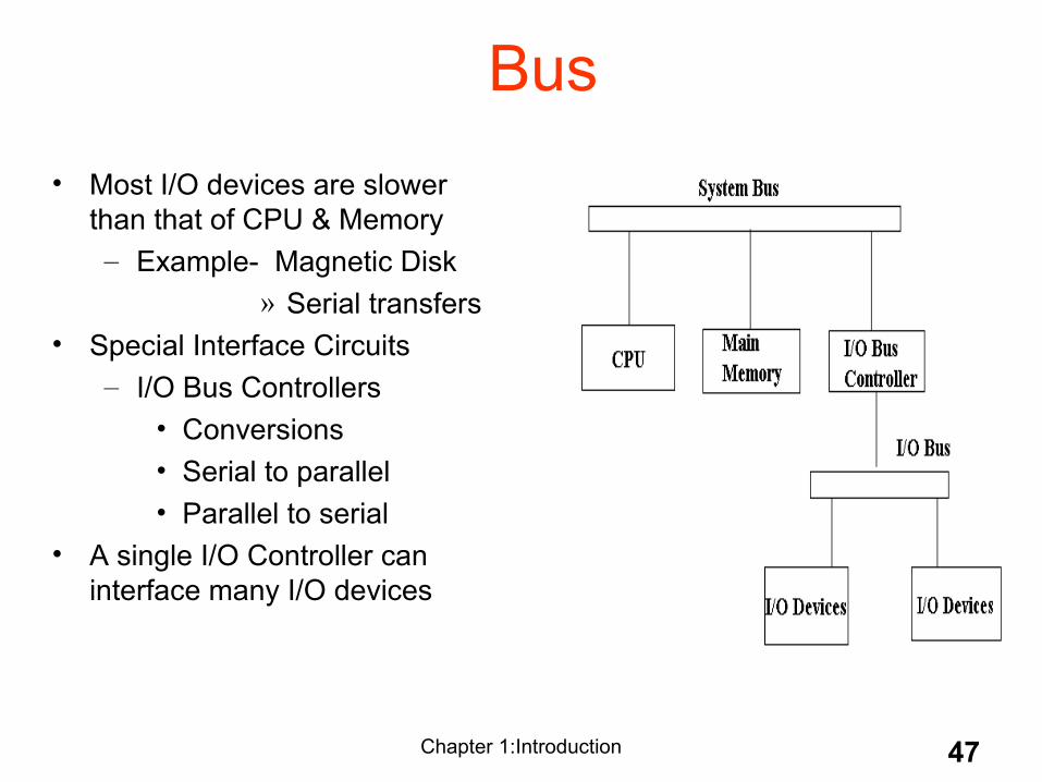
Bus
• Most I/O devices are slower than that of CPU & Memory
– Example- Magnetic Disk » Serial transfers
• Special Interface Circuits– I/O Bus Controllers
• Conversions• Serial to parallel• Parallel to serial
• A single I/O Controller can interface many I/O devices
Need for Bus Arbitration
A bus master wanting to use the bus asserts the bus request
A bus master cannot use the bus until its request is granted
A bus master must signal to the arbiter after finish using the bus
Bus arbitration schemes usually try to balance two factors:
Bus priority:
the highest priority device should be service first
Fairness:
Even the lowest priority device should never be completely locked out from the bus

Daisy Chaining Bus Arbitration
Control Signals
Bus Request
Bus Busy
Bus Grant
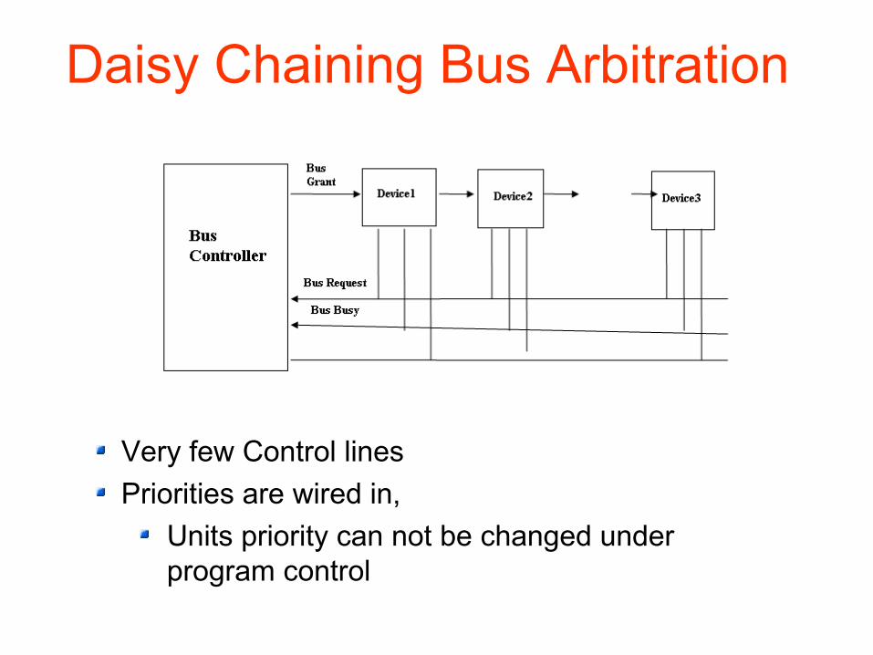
Daisy Chaining Bus Arbitration
Very few Control lines
Priorities are wired in,
Units priority can not be changed under program control

Priorities are wired in,
Units priority can be changed under program control

Chapter 1:Introduction 52
• This chapter has given you an overview of the subject of computer architecture.
• You should now be sufficiently familiar with general system structure to guide your studies throughout the remainder of this course.
• Subsequent chapters will explore many of these topics in great detail.
Conclusion
Chapter 1:Introduction 53
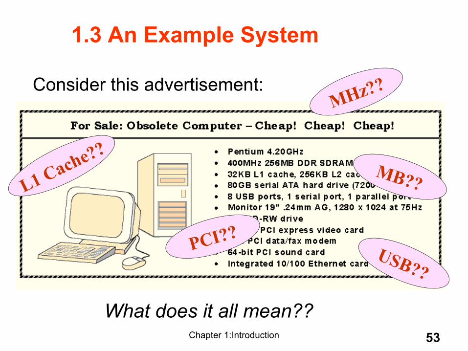
Consider this advertisement:
1.3 An Example System
MHz??
MB??
PCI??USB??
L1 Cache??
What does it all mean??

Chapter 1:Introduction 54
Measures of capacity and speed:• Kilo- (K) = 1 thousand = 103 and 210
• Mega- (M) = 1 million = 106 and 220
• Giga- (G) = 1 billion = 109 and 230
• Tera- (T) = 1 trillion = 1012 and 240
• Peta- (P) = 1 quadrillion = 1015 and 250
• Exa- (E) = 1 quintillion = 1018 and 260
• Zetta-(Z) = 1 sextillion = 1021 and 270
• Yotta-(Y) = 1 septillion = 1024 and 280
1.3 An Example SystemWhether a metric refers to a power of ten or a power of two typically depends upon what is being measured.
• Hertz = clock cycles per second (frequency)– 1MHz = 1,000,000Hz– Processor speeds are measured in MHz or GHz.
• Byte = a unit of storage– 1KB = 210 = 1024 Bytes– 1MB = 220 = 1,048,576 Bytes– Main memory (RAM) is measured in MB– Disk storage is measured in GB for small systems,
TB for large systems.

Chapter 1:Introduction 55
1.3 An Example System
Measures of time and space:• Milli- (m) = 1 thousandth = 10 -3
• Micro- () = 1 millionth = 10 -6
• Nano- (n) = 1 billionth = 10 -9
• Pico- (p) = 1 trillionth = 10 -12
• Femto- (f) = 1 quadrillionth = 10 -15
• Atto- (a) = 1 quintillionth = 10 -18
• Zepto- (z) = 1 sextillionth = 10 -21
• Yocto- (y) = 1 septillionth = 10 -24
• Millisecond = 1 thousandth of a second– Hard disk drive access times are often 10 to 20 milliseconds.
• Nanosecond = 1 billionth of a second– Main memory access times are often 50 to 70 nanoseconds.
• Micron (micrometer) = 1 millionth of a meter– Circuits on computer chips are measured in microns.
• We note that cycle time is the reciprocal of clock frequency.
• A bus operating at 133MHz has a cycle time of 7.52 nanoseconds:

Chapter 1:Introduction 56
1.3 An Example System
A system bus moves data within the computer. This one runs at 400MHz.
The microprocessor is the “brain” of the system. It executes program instructions. This one is a Pentium (Intel) running at 4.20GHz.

Chapter 1:Introduction 57
1.3 An Example System
• Computers with large main memory capacity can run larger programs with greater speed than computers having small memories.
• RAM is an acronym for random access memory. Random access means that memory contents can be accessed directly if you know its location.
• Cache is a type of temporary memory that can be accessed faster than RAM.

Chapter 1:Introduction 58
1.3 An Example System
… and two levels of cache memory, the level 1 (L1) cache is smaller and (probably) faster than the L2 cache. Note that these cache sizes are measured in KB.
This system has 256MB of (fast) synchronous dynamic RAM (SDRAM) . . .

Chapter 1:Introduction 59
1.3 An Example System
This one can store 80GB. 7200 RPM is the rotational speed of the disk. Generally, the faster a disk rotates, the faster it can deliver data to RAM. (There are many other factors involved.)
Hard disk capacity determines the amount of data and size of programs you can store.

Chapter 1:Introduction 60
1.3 An Example System
ATA stands for advanced technology attachment, which describes how the hard disk interfaces with (or connects to) other system components.
A CD can store about 650MB of data. This drive supports rewritable CDs, CD-RW, that can be written to many times.. 48x describes its speed.

Chapter 1:Introduction 61
1.3 An Example System
This system has ten ports.
Ports allow movement of data between a system and its external devices.
• Serial ports send data as a series of pulses along one or two data lines.
• Parallel ports send data as a single pulse along at least eight data lines.
• USB, Universal Serial Bus, is an intelligent serial interface that is self-configuring. (It supports “plug and play.”)

Chapter 1:Introduction 62
1.3 An Example System
System buses can be augmented by dedicated I/O buses. PCI, peripheral component interface, is one such bus.
This system has three PCI devices: a video card, a sound card, and a data/fax modem.

Chapter 1:Introduction 63
1.3 An Example System
System buses can be augmented by dedicated I/O buses. PCI, peripheral component interface, is one such bus.
Network interface built into the motherboard.