Comparision of BS5950 and EC3
151
PSZ 19:16 (Pind. 1/97) UNIVERSITI TEKNOLOGI MALAYSIA BORANG PENGESAHAN STATUS TESIS COMPARISON BETWEEN BS 5950: PART 1: 2000 & EUROCODE 3 FOR JUDUL: THE DESIGN OF MULTI-STOREY BRACED STEEL FRAME SESI PENGAJIAN: 2006 / 2007 Saya CHAN CHEE HAN (HURUF BESAR) mengaku membenarkan tesis (PSM / Sarjana/ Doktor Falsafah )* ini disimpan di Perpustakaan Universiti Teknologi Malaysia dengan syarat-syarat kegunaan seperti berikut: 1. Tesis adalah hakmilik Universiti Teknologi Malaysia. 2. Perpustakaan Universiti Teknologi Malaysia dibenarkan membuat salinan untuk tujuan pengajian sahaja. 3. Perpustakaan dibenarkan membuat salinan tesis ini sebagai bahan pertukaran antara institusi pengajian tinggi. 4. **Sila tandakan ( ) SULIT (Mengandungi maklumat yang berdarjah keselamatan atau kepentingan Malaysia seperti yang termaktub di dalam (AKTA RAHSIA RASMI 1972) TERHAD (Mengandungi maklumat TERHAD yang telah ditentukan oleh organisasi/ badan di mana penyelidikan dijalankan) TIDAK TERHAD Disahkan oleh (TANDATANGAN PENULIS) (TANDATANGAN PENYELIA) Alamat Tetap: PETI SURAT 61162, 91021 TAWAU, PM DR. IR. MAHMOOD MD. TAHIR SABAH. Nama Penyelia : 01 NOVEMBER 2006 : 01 NOVEMBER 2006 Tarikh Tarikh: CATATAN: * Potong yang tidak berkenaan. ** Jika tesis ini SULIT atau TERHAD, sila lampirkan surat daripada pihak berkuasa/ organisasi berkenaan dengan menyatakan sekali sebab dan tempoh tesis ini perlu dikelaskan sebagai SULIT atau TERHAD. υ Tesis dimaksudkan sebagai tesis bagi Ijazah Doktor Falsafah dan Sarjana secara penyelidikan, atau disertasi bagi pengajian secara kerja kursus dan penyelidikan, atau Laporan Projek Sarjana Muda (PSM). υ
-
Upload
ganeshkonar -
Category
Documents
-
view
157 -
download
10
description
Comparision of BS5950 and EC3
Transcript of Comparision of BS5950 and EC3
PSZ 19:16 (Pind. 1/97)
UNIVERSITI TEKNOLOGI MALAYSIA
BORANG PENGESAHAN STATUS TESIS COMPARISON BETWEEN BS 5950: PART 1: 2000 & EUROCODE 3 FOR JUDUL: THE DESIGN OF MULTI-STOREY BRACED STEEL FRAME
SESI PENGAJIAN: 2006 / 2007
Saya CHAN CHEE HAN (HURUF BESAR)
mengaku membenarkan tesis (PSM/ Sarjana/ Doktor Falsafah)* ini disimpan di Perpustakaan Universiti Teknologi Malaysia dengan syarat-syarat kegunaan seperti berikut:
1. Tesis adalah hakmilik Universiti Teknologi Malaysia. 2. Perpustakaan Universiti Teknologi Malaysia dibenarkan membuat salinan untuk
tujuan pengajian sahaja. 3. Perpustakaan dibenarkan membuat salinan tesis ini sebagai bahan pertukaran antara
institusi pengajian tinggi. 4. **Sila tandakan ( )
SULIT (Mengandungi maklumat yang berdarjah keselamatan atau kepentingan Malaysia seperti yang termaktub di dalam (AKTA RAHSIA RASMI 1972)
TERHAD (Mengandungi maklumat TERHAD yang telah ditentukan oleh organisasi/ badan di mana penyelidikan dijalankan)
TIDAK TERHAD
Disahkan oleh
(TANDATANGAN PENULIS) (TANDATANGAN PENYELIA)
Alamat Tetap:
PETI SURAT 61162,
91021 TAWAU, PM DR. IR. MAHMOOD MD. TAHIR SABAH.
Nama Penyelia
: 01 NOVEMBER 2006 : 01 NOVEMBER 2006
Tarikh
Tarikh:
CATATAN: *
Potong yang tidak berkenaan.
** Jika tesis ini SULIT atau TERHAD, sila lampirkan surat daripada pihak berkuasa/ organisasi berkenaan dengan menyatakan sekali sebab dan tempoh tesis ini perlu dikelaskan sebagai SULIT atau TERHAD.
υ
Tesis dimaksudkan sebagai tesis bagi Ijazah Doktor Falsafah dan Sarjana secara penyelidikan, atau disertasi bagi pengajian secara kerja kursus dan penyelidikan, atau Laporan Projek Sarjana Muda (PSM).
υ
“I hereby declare that I have read this project report and in
my opinion this project report is sufficient in terms of scope and
quality for the award of the degree of Master of Engineering
(Civil – Structure).”
Signature :
Name of Supervisor : P.M. Dr. Ir. Mahmood Md. Tahir
Date : 01 NOVEMBER 2006
i
COMPARISON BETWEEN BS 5950: PART 1: 2000 & EUROCODE 3 FOR THE
DESIGN OF MULTI-STOREY BRACED STEEL FRAME
CHAN CHEE HAN
A project report submitted as partial fulfillment of the
requirements for the award of the degree of
Master of Engineering (Civil – Structure)
Faculty of Civil Engineering
Universiti Teknologi Malaysia
NOVEMBER, 2006
ii
I declare that this project report entitled “Comparison Between BS 5950: Part 1:
2000 & Eurocode 3 for The Design of Multi-Storey Braced Steel Frame” is the result
of my own research except as cited in the references. The report has not been
accepted for any degree and is not concurrently submitted in candidature of any other
degree.
Signature :
Name : Chan Chee Han
Date : 01 NOVEMBER 2006

iii
To my beloved parents and siblings

iv
ACKNOWLEDGEMENT
First of all, I would like to express my appreciation to my thesis supervisor,
PM. Dr. Ir. Mahmood Md. Tahir of the Faculty of Civil Engineering, Universiti
Teknologi Malaysia, for his generous advice, patience and guidance during the
duration of my study.
I would also like to express my thankful appreciation to Dr. Mahmood’s
research students, Mr. Shek and Mr. Tan for their helpful guidance in the process of
completing this study.
Finally, I am most thankful to my parents and family for their support and
encouragement given to me unconditionally in completing this task.
Without the contribution of all those mentioned above, this work would not
have been possible.
v
ABSTRACT
Reference to standard code is essential in the structural design of steel
structures. The contents of the standard code generally cover comprehensive details
of a design. These details include the basis and concept of design, specifications to
be followed, design methods, safety factors, loading values and etc. The Steel
Construction Institute (SCI) claimed that a steel structural design by using Eurocode
3 is 6 – 8% more cost-saving than using BS 5950: Part 1: 2000. This study intends to
testify the claim. This paper presents comparisons of findings on a series of two-bay,
four-storey braced steel frames with spans of 6m and 9m and with steel grade S275
(Fe 460) and S355 (Fe 510) by designed using BS 5950: Part 1: 2000 and Eurocode 3.
Design worksheets are created for the design of structural beam and column. The
design method by Eurocode 3 has reduced beam shear capacity by up to 4.06% and
moment capacity by up to 6.43%. Meanwhile, structural column designed by
Eurocode 3 has compression capacity of between 5.27% and 9.34% less than BS
5950: Part 1:2000 design. Eurocode 3 also reduced the deflection value due to
unfactored imposed load of up to 3.63% in comparison with BS 5950: Part 1: 2000.
However, serviceability limit states check governs the design of Eurocode 3 as
permanent loads have to be considered in deflection check. Therefore, Eurocode 3
produced braced steel frames which consume 1.60% to 17.96% more steel weight
than the ones designed with BS 5950: Part 1: 2000. However, with the application of
partial strength connections, the percentage of difference had been reduced to the
range of 0.11% to 10.95%.
vi
ABSTRAK
Dalam rekabentuk struktur keluli, rujukan kepada kod piawai adalah penting.
Kandungan dalam kod piawai secara amnya mengandungi butiran rekabentuk yang
komprehensif. Butiran-butiran ini mengandungi asas dan konsep rekabentuk,
spesifikasi yang perlu diikuti, cara rekabentuk, factor keselamatan, nilai beban, dan
sebagainya. Institut Pembinaan Keluli (SCI) berpendapat bahawa rekabentuk struktur
keluli menggunakan Eurocode 3 adalah 6 – 8% lebih menjimatkan daripada
menggunakan BS 5950: Part 1: 2000. Kajian ini bertujuan menguji pendapat ini.
Kertas ini menunjukkan perbandingan keputusan kajian ke atas satu siri kerangka
besi terembat 2 bay, 4 tingkat yang terdiri daripada rentang rasuk 6m dan 9m serta
gred keluli S275 (Fe 430) dan S355 (Fe 510). Kertas kerja komputer ditulis untuk
merekabentuk rasuk dan tiang keluli. Rekebentuk menggunakan Eurocode 3 telah
mengurangkan keupayaan ricih rasuk sehingga 4.06% dan keupayaan momen rasuk
sebanyak 6.43%. Selain itu, tiang keluli yang direkebentuk oleh Eurocode 3
mempunyai keupayaan mampatan 5.27% – 9.34% kurang daripada rekabentuk
menggunakan BS 5950: Part 1: 2000. Eurocode 3 juga mengurangkan nilai pesongan
yang disebabkan oleh beban kenaan tanpa faktor sehingga 3.63% berbanding BS
5950: Part 1: 2000. Namun begitu, didapati bahawa keadaan had kebolehkhidmatan
mengawal rekabentuk Eurocode 3 disebabkan beban mati tanpa faktor yang perlu
diambilkira dalam pemeriksaan pesongan. Justeru, Eurocode 3 menghasilkan
kerangka keluli dirembat yang menggunakan berat besi 1.60% – 17.96% lebih
banyak daripada kerangka yang direkabentuk oleh BS 5950: Part 1: 2000. Namun
begitu, penggunaan sambungan kekuatan separa telah berjaya mengurangkan
lingkungan berat besi kepada 0.11% – 10.95%.
vii
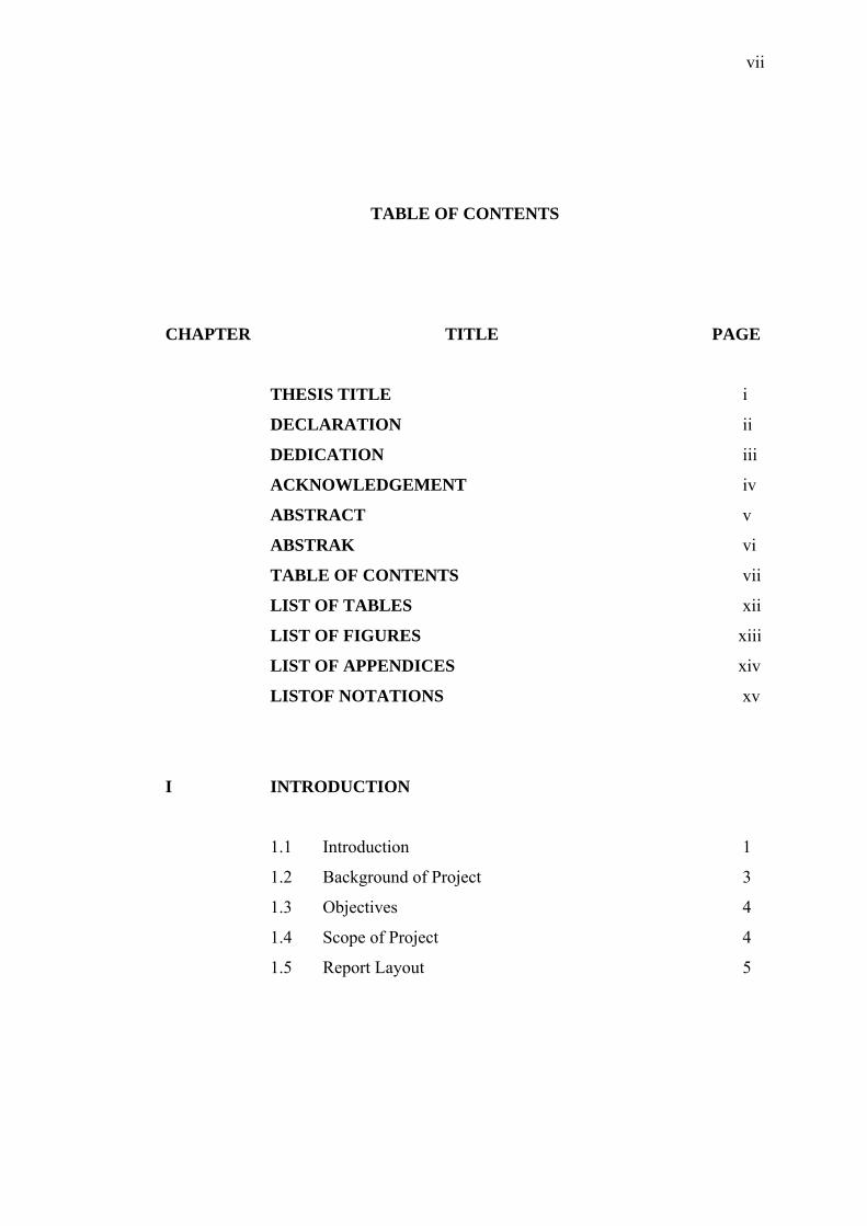
TABLE OF CONTENTS
CHAPTER TITLE PAGE
THESIS TITLE i
DECLARATION ii
DEDICATION iii
ACKNOWLEDGEMENT iv
ABSTRACT v
ABSTRAK vi
TABLE OF CONTENTS vii
LIST OF TABLES xii
LIST OF FIGURES xiii
LIST OF APPENDICES xiv
LISTOF NOTATIONS xv
I INTRODUCTION
1.1 Introduction 1
1.2 Background of Project 3
1.3 Objectives 4
1.4 Scope of Project 4
1.5 Report Layout 5
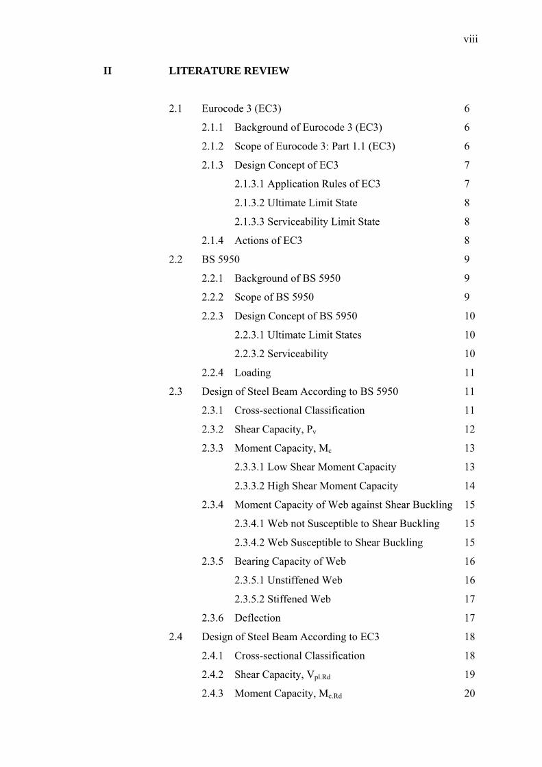
viii
II LITERATURE REVIEW
2.1 Eurocode 3 (EC3) 6
2.1.1 Background of Eurocode 3 (EC3) 6
2.1.2 Scope of Eurocode 3: Part 1.1 (EC3) 6
2.1.3 Design Concept of EC3 7
2.1.3.1 Application Rules of EC3 7
2.1.3.2 Ultimate Limit State 8
2.1.3.3 Serviceability Limit State 8
2.1.4 Actions of EC3 8
2.2 BS 5950 9
2.2.1 Background of BS 5950 9
2.2.2 Scope of BS 5950 9
2.2.3 Design Concept of BS 5950 10
2.2.3.1 Ultimate Limit States 10
2.2.3.2 Serviceability 10
2.2.4 Loading 11
2.3 Design of Steel Beam According to BS 5950 11
2.3.1 Cross-sectional Classification 11
2.3.2 Shear Capacity, Pv 12
2.3.3 Moment Capacity, Mc 13
2.3.3.1 Low Shear Moment Capacity 13
2.3.3.2 High Shear Moment Capacity 14
2.3.4 Moment Capacity of Web against Shear Buckling 15
2.3.4.1 Web not Susceptible to Shear Buckling 15
2.3.4.2 Web Susceptible to Shear Buckling 15
2.3.5 Bearing Capacity of Web 16
2.3.5.1 Unstiffened Web 16
2.3.5.2 Stiffened Web 17
2.3.6 Deflection 17
2.4 Design of Steel Beam According to EC3 18
2.4.1 Cross-sectional Classification 18
2.4.2 Shear Capacity, Vpl.Rd 19
2.4.3 Moment Capacity, Mc.Rd 20
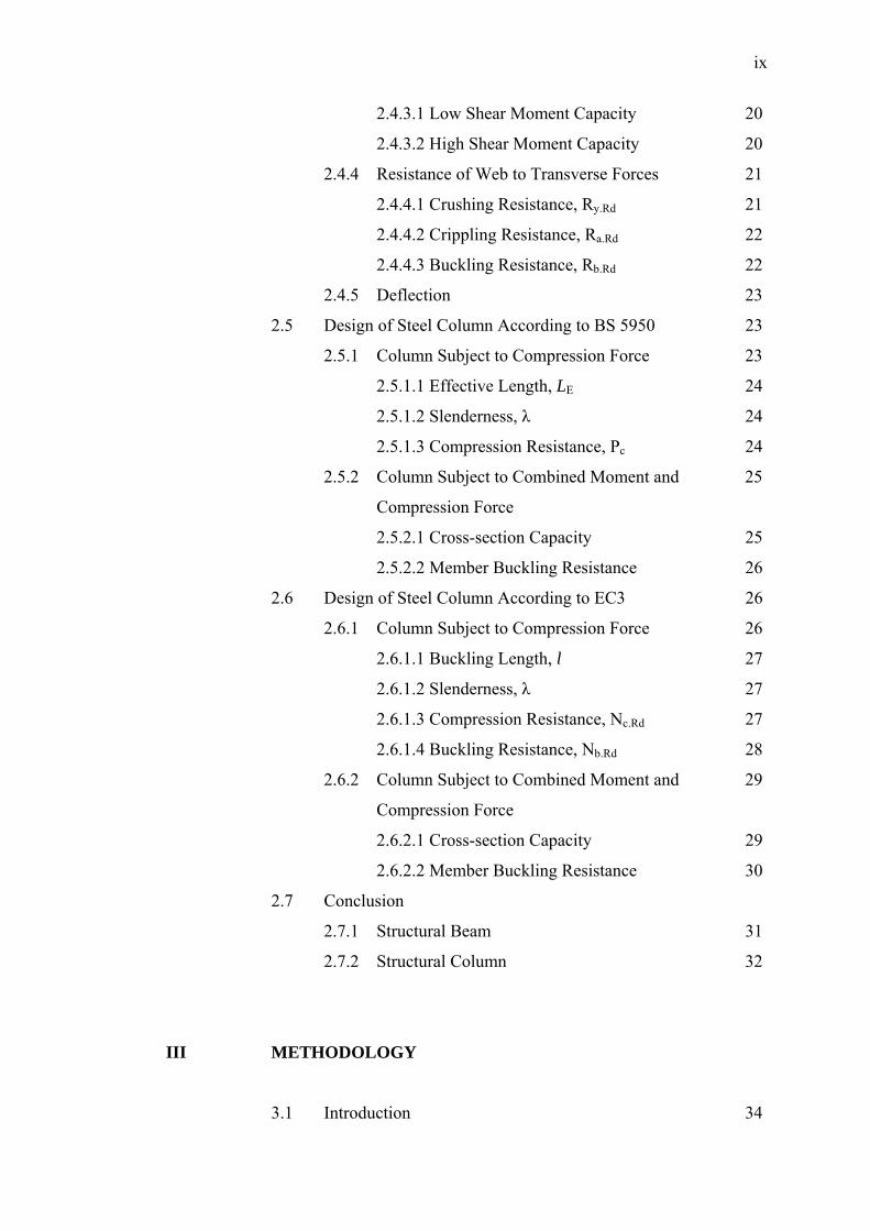
ix
2.4.3.1 Low Shear Moment Capacity 20
2.4.3.2 High Shear Moment Capacity 20
2.4.4 Resistance of Web to Transverse Forces 21
2.4.4.1 Crushing Resistance, Ry.Rd 21
2.4.4.2 Crippling Resistance, Ra.Rd 22
2.4.4.3 Buckling Resistance, Rb.Rd 22
2.4.5 Deflection 23
2.5 Design of Steel Column According to BS 5950 23
2.5.1 Column Subject to Compression Force 23
2.5.1.1 Effective Length, LE 24
2.5.1.2 Slenderness, λ 24
2.5.1.3 Compression Resistance, Pc 24
2.5.2 Column Subject to Combined Moment and 25
Compression Force
2.5.2.1 Cross-section Capacity 25
2.5.2.2 Member Buckling Resistance 26
2.6 Design of Steel Column According to EC3 26
2.6.1 Column Subject to Compression Force 26
2.6.1.1 Buckling Length, l 27
2.6.1.2 Slenderness, λ 27
2.6.1.3 Compression Resistance, Nc.Rd 27
2.6.1.4 Buckling Resistance, Nb.Rd 28
2.6.2 Column Subject to Combined Moment and 29
Compression Force
2.6.2.1 Cross-section Capacity 29
2.6.2.2 Member Buckling Resistance 30
2.7 Conclusion
2.7.1 Structural Beam 31
2.7.2 Structural Column 32
III METHODOLOGY
3.1 Introduction 34
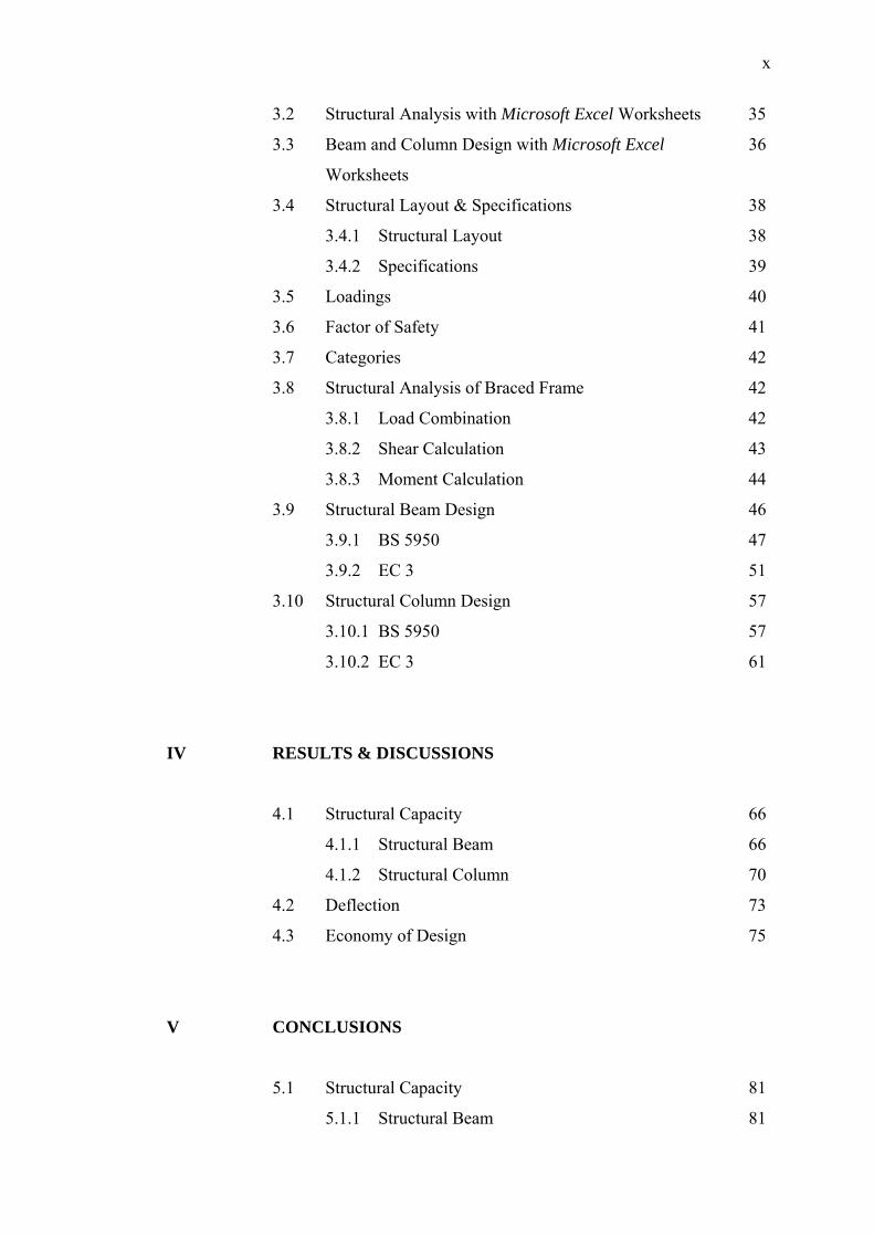
x
3.2 Structural Analysis with Microsoft Excel Worksheets 35
3.3 Beam and Column Design with Microsoft Excel 36
Worksheets
3.4 Structural Layout & Specifications 38
3.4.1 Structural Layout 38
3.4.2 Specifications 39
3.5 Loadings 40
3.6 Factor of Safety 41
3.7 Categories 42
3.8 Structural Analysis of Braced Frame 42
3.8.1 Load Combination 42
3.8.2 Shear Calculation 43
3.8.3 Moment Calculation 44
3.9 Structural Beam Design 46
3.9.1 BS 5950 47
3.9.2 EC 3 51
3.10 Structural Column Design 57
3.10.1 BS 5950 57
3.10.2 EC 3 61
IV RESULTS & DISCUSSIONS
4.1 Structural Capacity 66
4.1.1 Structural Beam 66
4.1.2 Structural Column 70
4.2 Deflection 73
4.3 Economy of Design 75
V CONCLUSIONS
5.1 Structural Capacity 81
5.1.1 Structural Beam 81
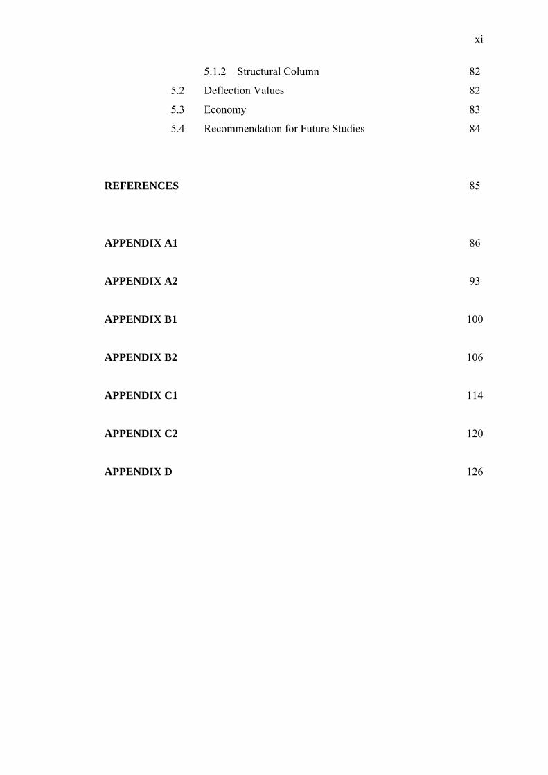
xi
5.1.2 Structural Column 82
5.2 Deflection Values 82
5.3 Economy 83
5.4 Recommendation for Future Studies 84
REFERENCES 85
APPENDIX A1 86
APPENDIX A2 93
APPENDIX B1 100
APPENDIX B2 106
APPENDIX C1 114
APPENDIX C2 120
APPENDIX D 126
xii
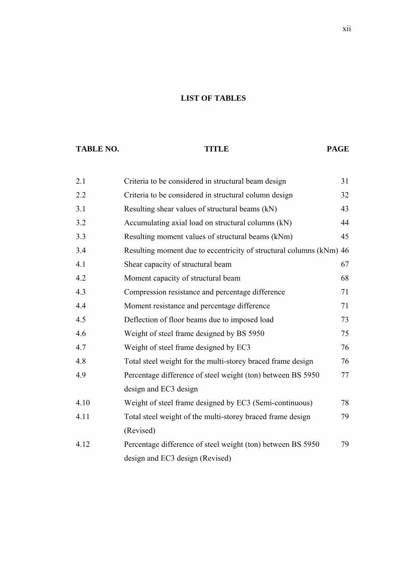
LIST OF TABLES
TABLE NO. TITLE PAGE
2.1 Criteria to be considered in structural beam design 31
2.2 Criteria to be considered in structural column design 32
3.1 Resulting shear values of structural beams (kN) 43
3.2 Accumulating axial load on structural columns (kN) 44
3.3 Resulting moment values of structural beams (kNm) 45
3.4 Resulting moment due to eccentricity of structural columns (kNm) 46
4.1 Shear capacity of structural beam 67
4.2 Moment capacity of structural beam 68
4.3 Compression resistance and percentage difference 71
4.4 Moment resistance and percentage difference 71
4.5 Deflection of floor beams due to imposed load 73
4.6 Weight of steel frame designed by BS 5950 75
4.7 Weight of steel frame designed by EC3 76
4.8 Total steel weight for the multi-storey braced frame design 76
4.9 Percentage difference of steel weight (ton) between BS 5950 77
design and EC3 design
4.10 Weight of steel frame designed by EC3 (Semi-continuous) 78
4.11 Total steel weight of the multi-storey braced frame design 79
(Revised)
4.12 Percentage difference of steel weight (ton) between BS 5950 79
design and EC3 design (Revised)
xiii
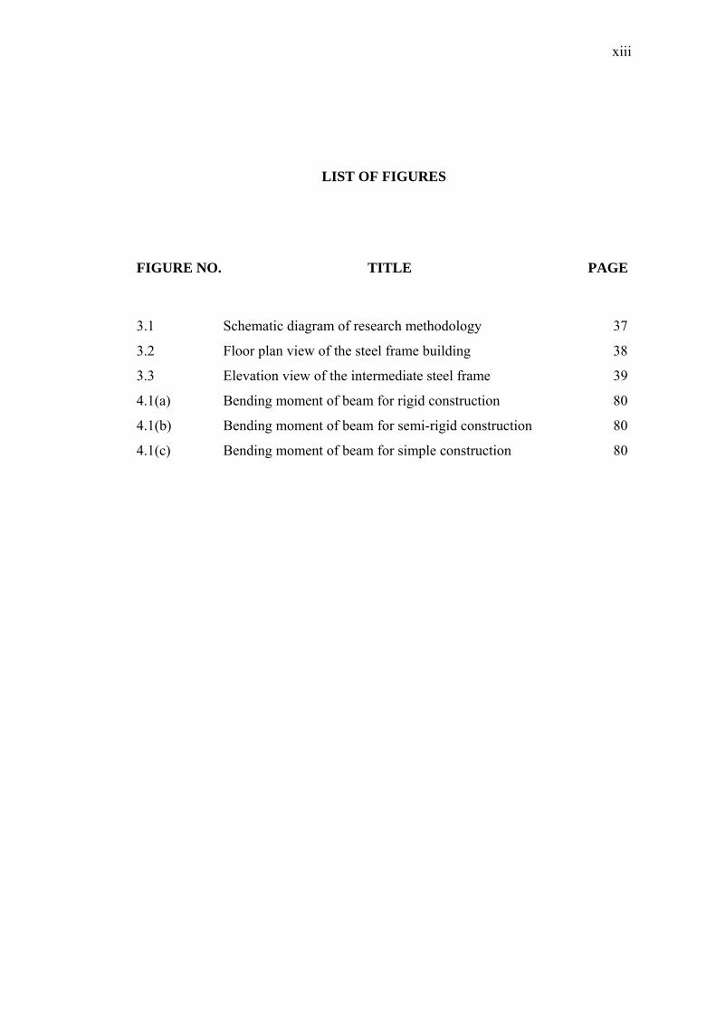
LIST OF FIGURES
FIGURE NO. TITLE PAGE
3.1 Schematic diagram of research methodology 37
3.2 Floor plan view of the steel frame building 38
3.3 Elevation view of the intermediate steel frame 39
4.1(a) Bending moment of beam for rigid construction 80
4.1(b) Bending moment of beam for semi-rigid construction 80
4.1(c) Bending moment of beam for simple construction 80
xiv
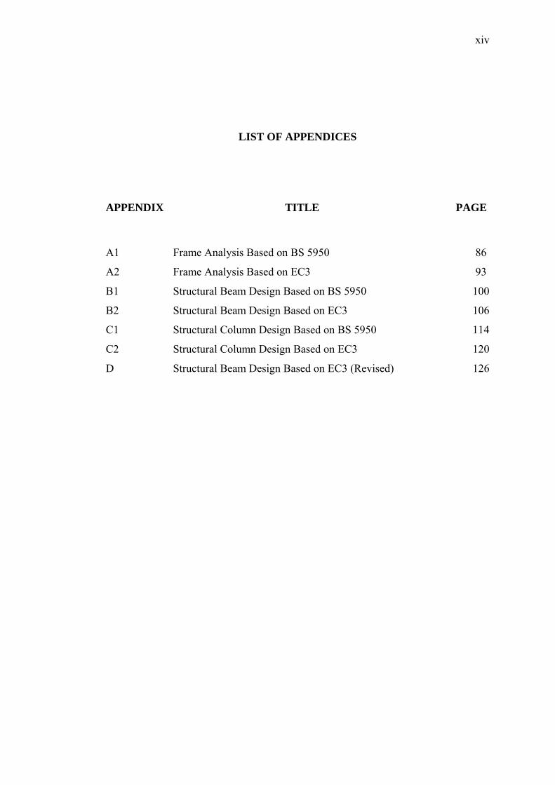
LIST OF APPENDICES
APPENDIX TITLE PAGE
A1 Frame Analysis Based on BS 5950 86
A2 Frame Analysis Based on EC3 93
B1 Structural Beam Design Based on BS 5950 100
B2 Structural Beam Design Based on EC3 106
C1 Structural Column Design Based on BS 5950 114
C2 Structural Column Design Based on EC3 120
D Structural Beam Design Based on EC3 (Revised) 126
xv
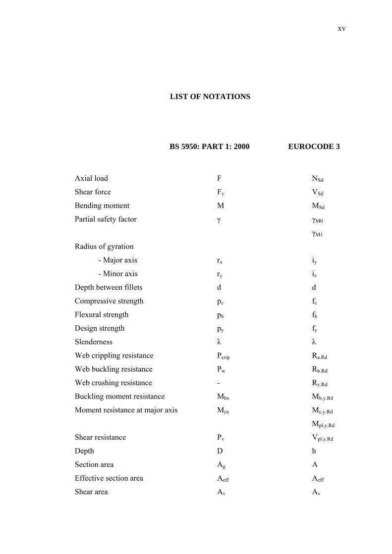
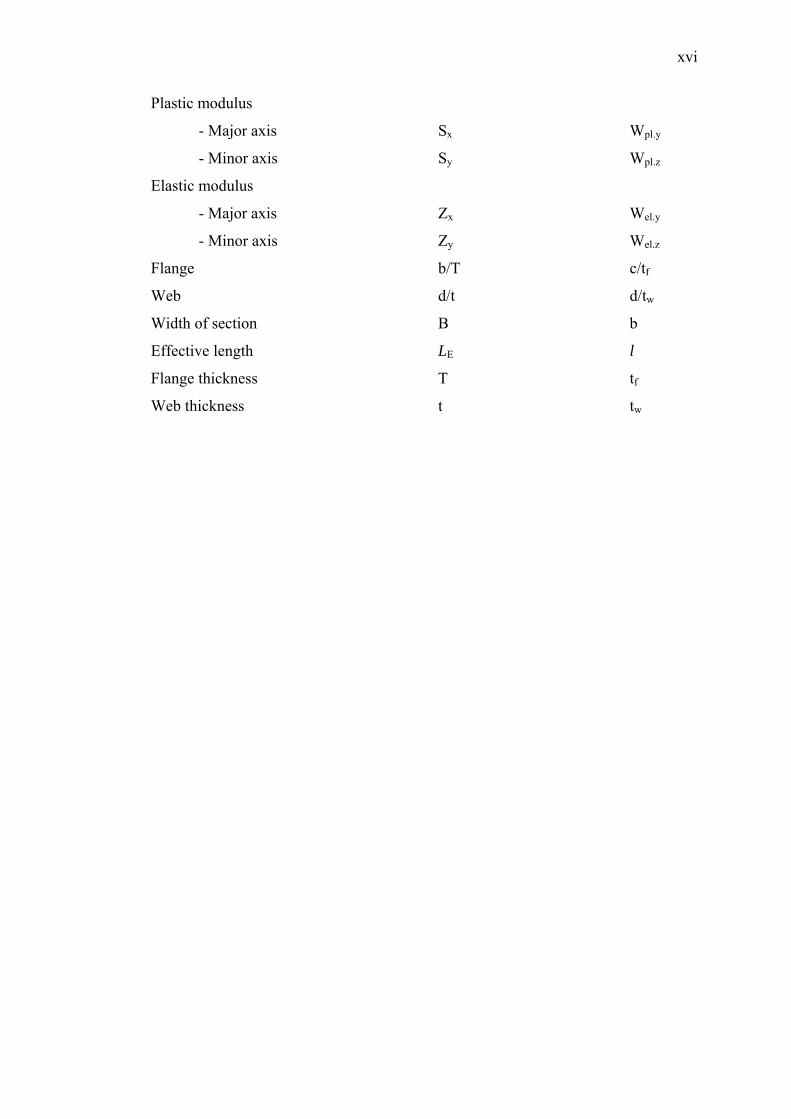
LIST OF NOTATIONS
BS 5950: PART 1: 2000 EUROCODE 3
Axial load F NSd
Shear force Fv VSd
Bending moment M MSd
Partial safety factor γ γM0
γM1
Radius of gyration
- Major axis rx iy
- Minor axis ry iz
Depth between fillets d d
Compressive strength pc fc
Flexural strength pb fb
Design strength py fy
Slenderness λ λ
Web crippling resistance Pcrip Ra.Rd
Web buckling resistance Pw Rb.Rd
Web crushing resistance - Ry.Rd
Buckling moment resistance Mbx Mb.y.Rd
Moment resistance at major axis Mcx Mc.y.Rd
Mpl.y.Rd
Shear resistance Pv Vpl.y.Rd
Depth D h
Section area Ag A
Effective section area Aeff Aeff
Shear area Av Av
xvi
Plastic modulus
- Major axis Sx Wpl.y
- Minor axis Sy Wpl.z
Elastic modulus
- Major axis Zx Wel.y
- Minor axis Zy Wel.z
Flange b/T c/tf
Web d/t d/tw
Width of section B b
Effective length LE l
Flange thickness T tf
Web thickness t tw
CHAPTER I
INTRODUCTION
1.1 Introduction
Structural design is a process of selecting the material type and conducting in-
depth calculation of a structure to fulfill its construction requirements. The main purpose
of structural design is to produce a safe, economic and functional building. Structural
design should also be an integration of art and science. It is a process of converting an
architectural perspective into a practical and reasonable entity at construction site.
In the structural design of steel structures, reference to standard code is essential.
A standard code serves as a reference document with important guidance. The contents
of the standard code generally cover comprehensive details of a design. These details
include the basis and concept of design, specifications to be followed, design methods,
safety factors, loading values and etc.
In present days, many countries have published their own standard codes. These
codes were a product of constant research and development, and past experiences of
experts at respective fields. Meanwhile, countries or nations that do not publish their
own standard codes will adopt a set of readily available code as the national reference.
Several factors govern the type of code to be adopted, namely suitability of application
of the code set in a country with respect to its culture, climate and national preferences;
as well as the trading volume and diplomatic ties between these countries.

2
Like most of the other structural Eurocodes, Eurocode 3 has developed in stages.
The earliest documents seeking to harmonize design rules between European countries
were the various recommendations published by the European Convention for
Constructional Steelwork, ECCS. From these, the initial draft Eurocode 3, published by
the European Commission, were developed. This was followed by the various parts of a
pre-standard code, ENV1993 (ENV stands for EuroNorm Vornorm) issued by Comité
Européen de Normalisation (CEN) – the European standardisation committee. These
preliminary standards of ENV will be revised, amended in the light of any comments
arising out of its use before being reissued as the EuroNorm standards (EN). As with
other Europeans standards, Eurocodes will be used in public procurement specifications
and to assess products for ‘CE’ (Conformité Européen) mark.
The establishment of Eurocode 3 will provide a common understanding
regarding the structural steel design between owners, operators and users, designers,
contractors and manufacturers of construction products among the European member
countries. It is believed that Eurocode 3 is more comprehensive and better developed
compared to national codes. Standardization of design code for structural steel in
Malaysia is primarily based on the practice in Britain. Therefore, the move to withdraw
BS 5950 and replace with Eurocode 3 will be taking place in the country as soon as all
the preparation has completed.
Codes of practice provide detailed guidance and recommendations on design of
structural elements. Buckling resistance and shear resistance are two major elements of
structural steel design. Therefore, provision for these topics is covered in certain sections
of the codes. The study on Eurocode 3 in this project will focus on the subject of
moment and shear design.
3
1.2 Background of Project
The arrival of Eurocode 3 calls for reconsideration of the approach to design.
Design can be complex, for those who pursue economy of material, but it can be
simplified for those pursuing speed and clarity. Many designers feel depressed when
new codes are introduced (Charles, 2005). There are new formulae and new
complications to master, even though there seems to be no benefit to the designer for the
majority of his regular workload.
The increasing complexity of codes arises due to several reasons; namely earlier
design over-estimated strength in a few particular circumstances, causing safety issues;
earlier design practice under-estimated strength in various circumstances affecting
economy; and new forms of structure evolve and codes are expanded to include them.
However, simple design is possible if a scope of application is defined to avoid
the circumstances and the forms of construction in which strength is over-estimated by
simple procedures. Besides, this can be achieved if the designer is not too greedy in the
pursuit of the least steel weight from the strength calculations. Finally, simple design is
possible if the code requirements are presented in an easy-to-use format, such as the
tables of buckling stresses in existing BS codes.
The Steel Construction Institute (SCI), in its publication of “eurocodesnews”
magazine has claimed that a steel structural design by using Eurocode 3 is 6 – 8% more
cost-saving than using BS 5950. Lacking analytical and calculative proof, this project is
intended to testify the claim.
4
1.3 Objectives
The objectives of this project are:
1) To compare the difference in the concept of the design using BS 5950: Part 1:
2000 and Eurocode 3.
2) To study on the effect of changing the steel grade from S275 to S355 in
Eurocode 3.
3) To compare the economy aspect between the designs of both BS 5950: Part 1:
2000 and Eurocode 3.
1.4 Scope of Project
The project focuses mainly on the moment and shear design on structural steel
members of a series four-storey, 2 bay braced frames. This structure is intended to serve
as an office building. All the beam-column connections are to be assumed simple. The
standard code used here will be Eurocode 3, hereafter referred to as EC3. A study on the
basis and design concept of EC3 will be carried out. Comparison to other steel structural
design code is made. The comparison will be made between the EC3 with BS 5950: Part
1: 2000, hereafter referred to as BS 5950.
The multi-storey steel frame will be first analyzed by using Microsoft Excel
worksheets to obtain the shear and moment values. Next, design spreadsheets will be
created to calculate and design the structural members.
5
1.5 Report Layout
The report will be divided into five main chapters.
Chapter I presents an introduction to the study. Chapter II presents the literature
review that discusses the design procedures and recommendations for steel frame design
of the codes EC3 and BS 5950. Chapter III will be a summary of research methodology.
Results and discussions are presented in Chapter IV. Meanwhile, conclusions and
recommendations are presented in Chapter V.
CHAPTER II
LITERATURE REVIEW
2.1 Eurocode 3 (EC3)
2.1.1 Background of Eurocode 3 (EC3)
European Code, or better known as Eurocode, was initiated by the Commission
of European Communities as a standard structural design guide. It was intended to
smooth the trading activities among the European countries. Eurocode is separated by
the use of different construction materials. Eurocode 1 covers loading situations;
Eurocode covers concrete construction; Eurocode 3 covers steel construction; while
Eurocode 4 covers for composite construction.
2.1.2 Scope of Eurocode 3: Part 1.1 (EC3)
EC3, “Design of Steel Structures: Part 1.1 General rules and rules for buildings”
covers the general rules for designing all types of structural steel. It also covers specific
rules for building structures. EC3 stresses the need for durability, serviceability and
resistance of a structure. It also covers other construction aspects only if they are
necessary for design. Principles and application rules are also clearly stated. Principles
should be typed in Roman wordings. Application rules must be written in italic style.
The use of local application rules are allowed only if they have similar principles as EC3
7
and their resistance, durability and serviceability design does not differ too much. EC3
stresses the need for durability, serviceability and resistance of structure (Taylor, 2001).
It also covers other construction aspects only if they are necessary for design.
2.1.3 Design Concept of EC3
All designs are based on limit state design. EC3 covers two limit states, which
are ultimate limit state and serviceability limit state. Partial safety factor is applied to
loadings and design for durability. Safety factor values are recommended in EC3. Every
European country using EC3 has different loading and material standard to
accommodate safety limit that is set by respective countries.
2.1.3.1 Application Rules of EC3
A structure should be designed and constructed in such a way that: with
acceptable probability, it will remain fit for the use for which it is required, having due
regard to its intended life and its cost; and with appropriate degrees of reliability, it will
sustain all actions and other influences likely to occur during execution and use and
have adequate durability in relation to maintenance costs. It should also be designed in
such a way that it will not be damaged by events like explosions, impact or
consequences of human errors, to an extent disproportionate to the original cause.
Potential damage should be limited or avoided by appropriate choice of one or
more of the following criteria: Avoiding, eliminating or reducing the hazards which the
structure is to sustain; selecting a structural form which has low sensitivity to the
hazards considered; selecting a structural form and design that can survive adequately
the accidental removal of an individual element; and tying the structure together.
8
2.1.3.2 Ultimate Limit State
Ultimate limit states are those associated with collapse, or with other forms of
structural failure which may endanger the safety of people. Partial or whole of structure
will suffer from failure. This failure may be caused by excessive deformation, rupture,
or loss of stability of the structure or any part of it, including supports and foundations,
and loss of equilibrium of the structure or any part of it, considered as a rigid body.
2.1.3.3 Serviceability Limit State
Serviceability limit states correspond to states beyond which specified service
criteria are no longer met. It may require certain consideration, including: deformations
or deflections which adversely affect the appearance or effective use of the structure
(including the proper functioning of machines or services) or cause damage to finishes
or non-structural elements; and vibration, which causes discomfort to people, damage to
the building or its contents, or which limits its functional effectiveness.
2.1.4 Actions of EC3
An action (F) is a force (load) applied to the structure in direct action, or an
imposed deformation in indirect action; for example, temperature effects or settlement.
Actions are classified by variation in time and by their spatial variation.
In time variation classification, actions can be grouped into permanent actions
(G), e.g. self-weight of structures, fittings, ancillaries and fixed equipment; variable
actions (Q), e.g. imposed loads, wind loads or snow loads; and accidental loads (A), e.g.
explosions or impact from vehicles. Meanwhile, in spatial variation classification,
actions are defined as fixed actions, e.g. self-weight; and free actions, which result in
different arrangements of actions, e.g. movable imposed loads, wind loads, snow loads.
9
2.2 BS 5950
2.2.1 Background of BS 5950
BS 5950 was prepared to supersede BS 5950: Part 1: 1990, which was
withdrawn. Several clauses were technically updated for topics such as sway stability,
avoidance of disproportionate collapse, local buckling, lateral-torsional buckling, shear
resistance, members subject to combined axial force and bending moment, etc. Changes
were due to structural safety, but offsetting potential reductions in economy was also
one of the reasons.
BS 5950 comprises of nine parts. Part 1 covers the code of practice for design of
rolled and welded sections; Part 2 and 7 deal with specification for materials, fabrication
and erected for rolled, welded sections and cold formed sections, sheeting respectively;
Part 3 and Part 4 focus mainly on composite design and construction; Part 5 concerns
design of cold formed thin gauge sections; Part 6 covers design for light gauge profiled
steel sheeting; Part 8 comprises of code of practice for fire resistance design; and Part 9
covers the code of practice for stressed skin design.
2.2.2 Scope of BS 5950
Part 1 of BS 5950 provides recommendations for the design of structural
steelwork using hot rolled steel sections, flats, plates, hot finished structural hollow
sections and cold formed structural hollow sections. They are being used in buildings
and allied structures not specifically covered by other standards.
10
2.2.3 Design Concept of BS 5950
There are several methods of design, namely simple design, continuous design,
semi-continuous design, and experimental verification. The fundamental of the methods
are different joints for different methods. Meanwhile, in the design for limiting states,
BS 5950 covers two types of states – ultimate limit states and serviceability limit states.
2.2.3.1 Ultimate Limit States
Several elements are considered in ultimate limit states. They are: strength,
inclusive of general yielding, rupture, buckling and mechanism formation; stability
against overturning and sway sensitivity; fracture due to fatigue; and brittle fracture.
Generally, in checking, the specified loads should be multiplied by the relevant partial
factors γf given in Table 2. The load carrying capacity of each member should be such
that the factored loads will not cause failure.
2.2.3.2 Serviceability Limit States
There are several elements to be considered in serviceability limit states –
Deflection, vibration, wind induced oscillation, and durability. Generally, serviceability
loads should be taken as the unfactored specified values. In the case of combined
imposed load and wind load, only 80% of the full specified values need to be considered
when checking for serviceability. In the case of combined horizontal crane loads and
wind load, only the greater effect needs to be considered when checking for
serviceability.
11
2.2.4 Loading
BS 5950 had identified and classified several loads that act on the structure.
There are dead, imposed and wind loading; overhead traveling cranes; earth and ground-
water loading. All relevant loads should be separately considered and combined
realistically as to compromise the most critical effects on the elements and the structure
as a whole. Loading conditions during erection should be given particular attention.
Where necessary, the settlement of supports should be taken into account as well.
2.3 Design of Steel Beam According to BS 5950
The design of simply supported steel beam covers all the elements stated below.
Sectional size chosen should satisfy the criteria as stated below:
(i) Cross-sectional classification
(ii) Shear capacity
(iii) Moment capacity (Low shear or High shear)
(iv) Moment Capacity of Web against Shear Buckling
(v) Bearing capacity of web
(vi) Deflection
2.3.1 Cross-sectional Classification
Cross-sections should be classified to determine whether local buckling
influences their capacity, without calculating their local buckling resistance. The
classification of each element of a cross-section subject to compression (due to a
bending moment or an axial force) should be based on its width-to-thickness ratio. The
elements of a cross-section are generally of constant thickness.
12
Generally, the complete cross-section should be classified according to the
highest (least favourable) class of its compression elements. Alternatively, a cross-
section may be classified with its compression flange and its web in different classes.
Class 1 is known as plastic section. It is cross-section with plastic hinge rotation
capacity. Class 1 section is used for plastic design as the plastic hinge rotation capacity
enables moment redistribution within the structure.
Class 2 is known as compact section. It enables plastic moment to take place.
However, local buckling will bar any rotation at constant moment.
Class 3 is known as semi-compact section. When this section is applied, the
stress at the extreme compression fiber can reach design strength. However, the plastic
moment capacity cannot be reached.
Class 4 is known as slender section. Sections that do not meet the limits for class
3 semi-compact sections should be classified as class 4 slender. Cross-sections at this
category should be given explicit allowance for the effects of local buckling.
2.3.2 Shear Capacity, Pv
The web of a section will sustain the shear in a structure. Shear capacity is
normally checked at section part that sustains the maximum shear force, Fv. Clause 4.2.3
of BS 5950 states the shear force Fv should not be greater than the shear capacity Pv,
given by:
Pv = 0.6pyAv
13
in which Av is the shear area. BS 5950 provides various formulas for different type of
sections. py is the design strength of steel and it depends on the thickness of the web.
2.3.3 Moment Capacity, Mc
At sectional parts that suffer from maximum moment, moment capacity of the
section needs to be verified. There are two situations to be verified in the checking of
moment capacity – low shear moment capacity and high shear moment capacity.
2.3.3.1 Low Shear Moment Capacity
This situation occurs when the maximum shear force Fv does not exceed 60% of
the shear capacity Pv. Clause 4.2.5.2 of BS 5950 states that:
Mc = pyS for class 1 plastic or class 2 compact cross-sections;
Mc = pyZ or alternatively Mc = pySeff for class 3 semi-compact sections; and
Mc = pyZeff for class 4 slender cross-sections
where S is the plastic modulus; Seff is the effective plastic modulus; Z is the section
modulus; and Zeff is the effective section modulus.
14
2.3.3.2 High Shear Moment Capacity
This situation occurs when the maximum shear force Fv exceeds 60% of the
shear capacity Pv. Clause 4.2.5.3 of BS 5950 states that:
Mc = py(S – ρSv) < 1.2pyZ for class 1 plastic or class 2 compact cross-sections;
Mc = py(Z – ρSv/1.5) or alternatively Mc = py(Seff – ρSv) for class 3 semi-compact
sections; and
Mc = py(Zeff – ρSv/1.5) for class 4 slender cross-sections
in which Sv is obtained from the following:
- For sections with unequal flanges:
Sv = S – Sf, in which Sf is the plastic modulus of the effective section excluding the
shear area Av.
- Otherwise:
Sv is the plastic modulus of the shear area Av.
and ρ is given by ρ = [2(Fv/Pv) – 1]2

15
2.3.4 Moment Capacity of Web against Shear Buckling
2.3.4.1 Web not Susceptible to Shear Buckling
Clause 4.4.4.1 of BS 5950 states that, if the web depth-to-thickness d/t ≤ 62ε, it
should be assumed not to be susceptible to shear buckling and the moment capacity of
the cross-section should be determined using 2.3.3.
2.3.4.2 Web Susceptible to Shear Buckling
Clause 4.4.4.2 states that, if the web depth-to-thickness ratio d/t > 70ε for a
rolled section, or 62ε for a welded section, it should be assumed to be susceptible to
shear buckling. The moment capacity of the cross-section should be determined taking
account of the interaction of shear and moment using the following methods:
a) Low shear
Provided that the applied shear Fv ≤ 0.6Vw, where Vw is the simple shear
buckling resistance,
Vw = dtqw
where
d = depth of the web;
qw = shear buckling strength of the web; obtained from Table 21 BS 5950
t = web thickness
b) High shear – “flanges only” method
If the applied shear Fv > 0.6Vw, but the web is designed for shear only,
provided that the flanges are not class 4 slender, a conservative value Mf for
16
the moment capacity may be obtained by assuming that the moment is
resisted by the flanges alone, with each flange subject to a uniform stress not
exceeding pyf, where pyf is the design strength of the compression flange.
c) High shear – General method
If the applied shear Fv > 0.6Vw, provided that the applied moment does not
exceed the “low-shear” moment capacity given in a), the web should be
designed using Annex H.3 for the applied shear combined with any
additional moment beyond the “flanges-only” moment capacity Mf given by
b).
2.3.5 Bearing Capacity of Web
2.3.5.1 Unstiffened Web
Clause 4.5.2.1 states that bearing stiffeners should be provided where the local
compressive force Fx applied through a flange by loads or reactions exceeds the bearing
capacity Pbw of the unstiffened web at the web-to-flange connection. It is given by:
Pbw = (b1 + nk)tpyw
in which, - except at the end of a member: n = 5
- at the end of a member: n = 2 + 0.6be/k but n ≤ 5
and k is obtained as follows:
- for a rolled I- or H-section: k = T + r
- for a welded I- or H-section: k = T
17
where b1 is the stiff bearing length; be is the distance to the nearer end of the member
from the end of the stiff bearing; pyw is the design strength of the web; r is the root
radius; T is the flange thickness; and t is the web thickness.
2.3.5.2 Stiffened Web
Bearing stiffeners should be designed for the applied force Fx minus the bearing
capacity Pbw of the unstiffened web. The capacity Ps of the stiffener should be obtained
from:
Ps = As.netpy
in which As.net is the net cross-sectional area of the stiffener, allowing for cope holes for
welding. If the web and the stiffener have different design strengths, the smaller value
should be used to calculate both the web capacity Pbw and the stiffener capacity Ps.
2.3.6 Deflection
Deflection checking should be conducted to ensure that the actual deflection of
the structure does not exceed the limit as allowed in the standard. Actual deflection is a
deflection caused by unfactored live load. Suggested limits for calculated deflections are
given in Table 8 of BS 5950.
18
2.4 Design of Steel Beam According to EC3
The design of simply supported steel beam covers all the elements stated below.
Sectional size chosen should satisfy the criteria as stated below:
(i) Cross-sectional classification
(ii) Shear capacity
(iii) Moment capacity (Low shear or High shear)
(iv) Bearing capacity of web
a) Crushing resistance
b) Crippling resistance
c) Buckling resistance
(v) Deflection
2.4.1 Cross-sectional Classification
A beam section should firstly be classified to determine whether the chosen
section will possibly suffer from initial local buckling. When the flange of the beam is
relatively too thin, the beam will buckle during pre-mature stage. To avoid this, Clause
5.3 of EC3 provided limits on the outstand-to-thickness (c/tf) for flange and depth-to-
thickness (d/tw) in Table 5.3.1. Beam sections are classified into 4 classes.
Class 1 is known as plastic section. It is applicable for plastic design. This limit
allows the formation of a plastic hinge with the rotation capacity required for plastic
analysis.
Class 2 is also known as compact section. This section can develop plastic
moment resistance. However, plastic hinge is disallowed because local buckling will
occur first. It has limited rotation capacity. It can also achieve rectangular stress block.
19
Class 3 is also known as semi-compact section. The stress block will be of
triangle shape. Calculated stress in the extreme compression fibre of the steel member
can reach its yield strength, but local buckling is liable to prevent development of the
plastic moment resistance.
Class 4 is known as slender section. Pre-mature buckling will occur before yield
strength is achieved. The member will fail before it reaches design stress. It is necessary
to make explicit allowances for the effects of local buckling when determining their
moment resistance or compression resistance. Apart from that, the ratios of c/tf and d/tw
will be the highest among all four classes.
2.4.2 Shear Capacity, Vpl.Rd
The web of a section will sustain shear from the structure. Shear capacity will
normally be checked at section that takes the maximum shear force, Vsd. At each cross-
section, the inequality should be satisfied:
Vsd ≤ Vpl.Rd
where Vpl.Rd = Av (fy / √3) / γMO
Av is the shear area. fy is the steel yield strength and γMO is partial safety factor
as stated in Clause 5.1.1.
Shear buckling resistance should be verified when for an unstiffened web, the
ratio of d/tw > 69ε or d/tw > 30ε √kγ for a stiffened web. kγ is the buckling factor for
shear, and ε = [235/fy]0,5
20
2.4.3 Moment Capacity, Mc.Rd
Moment capacity should be verified at sections sustaining maximum moment.
There are two situations to verify when checking moment capacity – that is, low shear
moment capacity and high shear moment capacity.
2.4.3.1 Low Shear Moment Capacity
When maximum shear force, Vsd is equal or less than the design resistance Vpl.Rd,
the design moment resistance of a cross-section Mc.Rd may be determined as follows:
Class 1 or 2 cross-sections: Mc.Rd = Wpl fy / γMO
Class 3 cross-sections: Mc.Rd = Wel fy / γMO
Class 4 cross-sections: Mc.Rd = Weff fy / γM1
where Wpl and Wel the plastic modulus and elastic modulus respectively. For class 4
cross-sections, Weff is the elastic modulus at effective shear area, as stated in Clause
5.3.5. γMO and γM1 are partial safety factors.
2.4.3.2 High Shear Moment Capacity
Clause 5.4.7 states that, when maximum shear force, Vsd exceeds 50% of the
design resistance Vpl.Rd, the design moment resistance of a cross-section should be
reduced to MV.Rd, the reduced design plastic resistance moment allowing for the shear
21
force. For cross-sections with equal flanges, bending about the major axis, it is obtained
as follows:
MV.Rd = (Wpl – ρAv
2/4tw) fy / γMO but MV.Rd ≤ Mc.Rd
where ρ = (2Vsd / Vpl.Rd – 1)2
2.4.4 Resistance of Web to Transverse Forces
The resistance of an unstiffened web to transverse forces applied through a
flange, is governed by one of the three modes of failure – Crushing of the web close to
the flange, accompanied by plastic deformation of the flange; crippling of the web in the
form of localized buckling and crushing of the web close to the flange, accompanied by
plastic deformation of the flange; and buckling of the web over most of the depth of the
member. However, if shear force acts directly at web without acting through flange in
the first place, this checking is unnecessary. This checking is intended to prevent the
web from buckling under excessive compressive force.
2.4.4.1 Crushing Resistance, Ry.Rd
Situation becomes critical when a point load is applied to the web. Thus,
checking should be done at section subject to maximum shear force. Clause 5.7.3
provides that the design crushing resistance, Ry.Rd of the web of an I, H or U section
should be obtained from:
Ry.Rd = (ss + sγ) tw fγw / γM1
in which sγ is given by sγ = 2tf (bf / tw)0,5 (fyf / fyw)0,5 [1 – (σf.Ed / fyf)2]0,5
22
but bf should not be taken as more than 25tf. σf.Ed is the longitudinal stress in the flange.
fyf and fyw are yield strength of steel at flange and web respectively.
2.4.4.2 Crippling Resistance, Ra.Rd
The design crippling resistance Ra.Rd of the web of an I, H or U section is given
by:
Ra.Sd = 0.5tw
2(Efyw)0,5 [(tf / tw)0,5 + 3(tw / tf)(ss / d)] / γM1
where ss is the length of stiff bearing, and ss / d < 0,2. For member subject to bending
moments, the following criteria should be satisfied:
Fsd ≤ Ra.Rd
Msd ≤ Mc.Rd
and Fsd / Ra.Rd + Msd / Mc.Rd ≤ 1,5
2.4.4.3 Buckling Resistance, Rb.Rd
The design buckling resistance Rb.Rd of the web of an I, H or U section should be
obtained by considering the web as a virtual compression member with an effective beff,
obtained from beff = [h2 + ss2]0,5.
Rb.Rd = (χ βA fy A) / γM1
23
where βA = 1 and buckling curve c is used at Table 5.5.1 and Table 5.5.2.
2.4.5 Deflection
Deflection checking should be conducted to ensure that the actual deflection of
the structure does not exceed the limit as allowed in the standard. Actual deflection is a
deflection caused by unfactored live load. Suggested limits for calculated deflections are
given in Table 4.1 of EC3.
2.5 Design of Steel Column According to BS 5950
The design of structural steel column is relatively easier than the design of
structural steel beam. Column is a compressive member and it generally supports
compressive point loads. Therefore, checking is normally conducted for capacity of steel
column to compression only. This, however, applies only to non-moment sustaining
column.
2.5.1 Column Subject to Compression Force
Cross-sectional classification of structural steel column is identical as of the
classification of structural steel beam. For a structural steel column subject to
compression load only, the following criteria should be checked:
(i) Effective length
(ii) Slenderness
(iii) Compression resistance
24
2.5.1.1 Effective Length, LE
The effective length LE of a compression member is determined from the
segment length L centre-to-centre of restraints or intersections with restraining members
in the relevant plane.
Depending on the conditions of restraint in the relevant plate, column members
that carry more than 90% of their reduced plastic moment capacity Mr in the presence of
axial force is assumed to be incapable of providing directional restraint.
For continuous columns in multi-storey buildings of simple design, in
accordance of Table 22, depending on the conditions of restraint in the relevant plane,
directional restraint is based on connection stiffness and member stiffness.
2.5.1.2 Slenderness, λ
The slenderness λ of a compression member is generally taken as its effective
length LE divided by its radius of gyration r about the relevant axis. This concept is not
applicable for battened struts, angle, channel, T-section struts, and back-to-back struts.
λ = LE / r
2.5.1.3 Compression Resistance, Pc
According to Clause 4.7.4, the compression resistance Pc of a member is given
by:
Pc = Ag pc (for class 1 plastic, class 2 compact and class 3 semi-compact cross-sections)
25
Pc = Aeff pcs (for class 4 slender cross-section)
where Aeff is the effective cross-sectional area; Ag is the gross cross-sectional area; pc
the compressive strength obtained from Table 23 and Table 24; and pcs is the value of pc
from Table 23 and Table 24 for a reduced slenderness of λ(Aeff/Ag)0.5, in which λ is
based on the radius of gyration r of the gross cross-section.
2.5.2 Column Subject to Combined Moment and Compression Force
For a column subject to combined moment and compression force, the cross-
section capacity and the member buckling resistance need to be checked.
2.5.2.1 Cross-section Capacity
Generally, for class 1 plastic, class 2 compact and class 3 semi-compact cross
sections, the checking of cross-section capacity is as follows:
1≤++cy
y
cx
x
yg
c
MM
MM
pAF
where Fc is the axial compression; Ag is the gross cross-sectional area; py is the design
steel strength; Mx is the moment about major axis; Mcx is the moment capacity about
major axis; My is the moment about minor axis; and Mcy is the moment capacity about
minor axis.
26
2.5.2.2 Member Buckling Resistance
In simple construction, the following stability check needs to be satisfied:
0.1≤++yy
y
bs
x
c ZpM
MM
PF
where F is the axial force in column; Pc the compression resistance of column; Mx the
maximum end moment on x-axis; Mb the buckling resistance moment; py the steel
design strength; and Zy the elastic modulus.
2.6 Design of Steel Column According to EC3
The design of steel column according to EC3 is quite similar to the design of
steel column according to BS 5950.
2.6.1 Column Subject to Compression Force
Cross-sectional classification of structural steel column is identical as of the
classification of structural steel beam. For a structural steel column subject to
compression load only, the following criteria should be checked:
(i) Buckling length
(ii) Slenderness
(iii) Compression resistance
(iv) Buckling resistance
27
2.6.1.1 Buckling Length, l
The buckling length l of a compression member is dependant on the restraint
condition at both ends. Clause 5.5.1.5 states that, provided that both ends of a column
are effectively held in position laterally, the buckling length l may be conservatively be
taken as equal to its system length L. Alternatively, the buckling length l may be
determined using informative of Annex E provided in EC3.
2.6.1.2 Slenderness, λ
The slenderness λ of a compression member is generally taken as its buckling
length l divided by its radius of gyration i about the relevant axis, determined using the
properties of the gross cross-section.
λ = l / i
For column resisting loads other than wind loads, the value of λ should not
exceed 180, whereas for column resisting self-weight and wind loads only, the value of
λ should not exceed 250.
2.6.1.3 Compression Resistance, Nc.Rd
According to Clause 5.4.4, the compression resistance Nc.Rd of a member is
given by:
Nc.Rd = A fy / γM0 (for class 1 plastic, class 2 compact and class 3 semi-compact cross-
sections)
28
Nc.Rd = Aeff fy / γM1 (for class 4 slender cross-section)
The design value of the compressive force NSd at each cross-section shall satisfy
the following condition:
NSd ≤ Nc.Rd
2.6.1.4 Buckling Resistance, Nb.Rd
For compression members, Clause 5.5.1.1 states that the design buckling
resistance of a compression member should be taken as:
Nc.Rd = χ βA A fy / γM1
where βA = 1 for Class 1, 2 or 3 cross-sections; and Aeff / A for Class 4 cross-sections. χ
is the reduction factor for the relevant buckling mode. For hot rolled steel members with
the types of cross-section commonly used for compression members, the relevant
buckling mode is generally “flexural” buckling.
The design value of the compressive force NSd at each cross-section shall satisfy
the following condition:
NSd ≤ Nb.Rd
29
2.6.2 Column Subject to Combined Moment and Compression Force
For a column subject to combined moment and compression force, the cross-
section capacity and the member buckling resistance need to be checked.
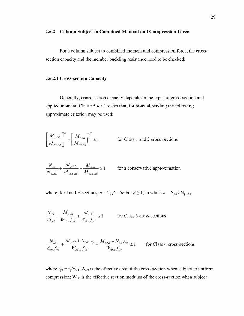
2.6.2.1 Cross-section Capacity
Generally, cross-section capacity depends on the types of cross-section and
applied moment. Clause 5.4.8.1 states that, for bi-axial bending the following
approximate criterion may be used:
1.
.
.
. ≤⎥⎦
⎤⎢⎣
⎡+
⎥⎥⎦
⎤
⎢⎢⎣
⎡ βα
RdNz
Sdz
RdNy
Sdy
MM
MM
for Class 1 and 2 cross-sections
1..
.
..
.
.
≤++Rdzpl
Sdz
Rdypl
Sdy
Rdpl
Sd
MM
MM
NN for a conservative approximation
where, for I and H sections, α = 2; β = 5n but β ≥ 1, in which n = Nsd / Npl.Rd.
1.
.
.
. ≤++ydzel
Sdz
ydyel
Sdy
yd
Sd
fWM
fWM
AfN for Class 3 cross-sections
1.
.
.
. ≤+
++
+ydzeff
NzSdSdz
ydyeff
NySdSdy
ydeff
Sd
fWeNM
fWeNM
fAN for Class 4 cross-sections
where fyd = fy/γM1; Aeff is the effective area of the cross-section when subject to uniform
compression; Weff is the effective section modulus of the cross-section when subject
30
only to moment about the relevant axis; and eN is the shift of the relevant centroidal axis
when the cross-section is subject to uniform compression.
However, for high shear (VSd ≥ 0.5 Vpl.Rd), Clause 5.4.9 states that the design
resistance of the cross-section to combinations of moment and axial force should be
calculated using a reduced yield strength of (1 – ρ)fy for the shear area, where ρ = (2VSd
/ Vpl.Rd – 1)2.
2.6.2.2 Member Buckling Resistance
A column, subject to buckling moment, may buckle about major axis or minor
axis or both. All members subject to axial compression NSd and major axis moment
My.Sd must satisfy the following condition:
0,1..
.
..
≤+Rdyc
Sdyy
Rdyb
Sd
MMk
NN
η
where Nb.y.Rd is the design buckling resistance for major axis; Mc.y.Rd is the design
moment resistance for major-axis bending, ky is the conservative value and taken as 1,5;
and η = γM0 / γM1 for Class 1, 2 or 3 cross-sections, but 1,0 for Class 4.
2.7 Conclusion
This section summarizes the general steps to be taken when designing a
structural member in simple construction.
31
2.7.1 Structural Beam
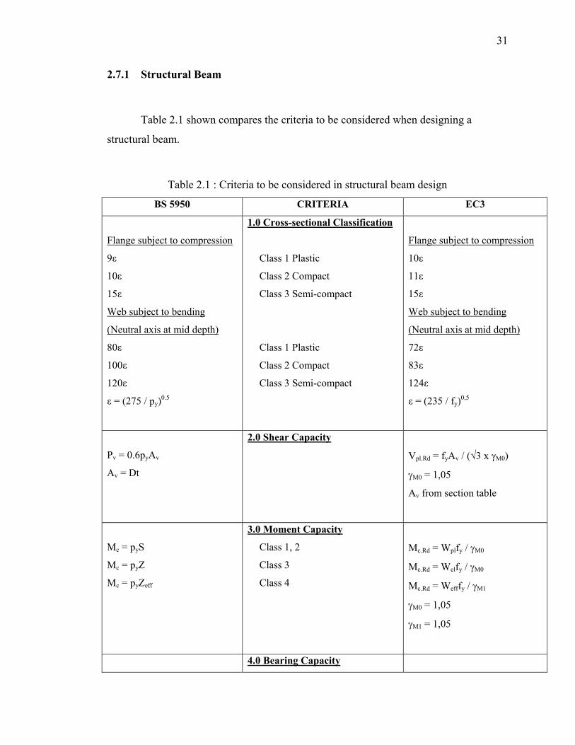
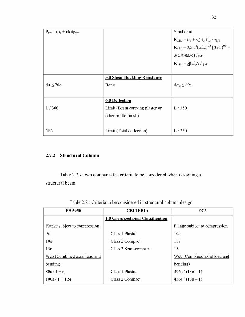
Table 2.1 shown compares the criteria to be considered when designing a
structural beam.
Table 2.1 : Criteria to be considered in structural beam design
BS 5950 CRITERIA EC3
Flange subject to compression
9ε
10ε
15ε
Web subject to bending
(Neutral axis at mid depth)
80ε
100ε
120ε
ε = (275 / py)0.5
1.0 Cross-sectional Classification
Class 1 Plastic
Class 2 Compact
Class 3 Semi-compact
Class 1 Plastic
Class 2 Compact
Class 3 Semi-compact
Flange subject to compression
10ε
11ε
15ε
Web subject to bending
(Neutral axis at mid depth)
72ε
83ε
124ε
ε = (235 / fy)0,5
Pv = 0.6pyAv
Av = Dt
2.0 Shear Capacity
Vpl.Rd = fyAv / (√3 x γM0)
γM0 = 1,05
Av from section table
Mc = pyS
Mc = pyZ
Mc = pyZeff
3.0 Moment Capacity
Class 1, 2
Class 3
Class 4
Mc.Rd = Wplfy / γM0
Mc.Rd = Welfy / γM0
Mc.Rd = Wefffy / γM1
γM0 = 1,05
γM1 = 1,05
4.0 Bearing Capacity
32
Pbw = (b1 + nk)tpyw
Smaller of
Ry.Rd = (ss + sy) tw fyw / γM1
Ra.Rd = 0,5tw2(Efyw)0,5 [(tf/tw)0,5 +
3(tw/tf)(ss/d)]/γM1
Rb.Rd = χβAfyA / γM1
d/t ≤ 70ε
5.0 Shear Buckling Resistance
Ratio
d/tw ≤ 69ε
L / 360
N/A
6.0 Deflection
Limit (Beam carrying plaster or
other brittle finish)
Limit (Total deflection)
L / 350
L / 250
2.7.2 Structural Column
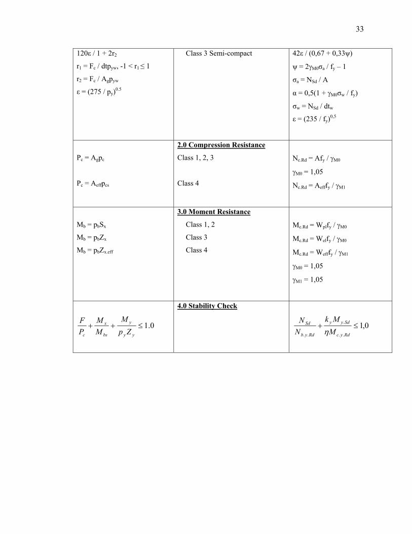
Table 2.2 shown compares the criteria to be considered when designing a
structural beam.
Table 2.2 : Criteria to be considered in structural column design
BS 5950 CRITERIA EC3
Flange subject to compression
9ε
10ε
15ε
Web (Combined axial load and
bending)
80ε / 1 + r1
100ε / 1 + 1.5r1
1.0 Cross-sectional Classification
Class 1 Plastic
Class 2 Compact
Class 3 Semi-compact
Class 1 Plastic
Class 2 Compact
Flange subject to compression
10ε
11ε
15ε
Web (Combined axial load and
bending)
396ε / (13α – 1)
456ε / (13α – 1)
33
120ε / 1 + 2r2
r1 = Fc / dtpyw, -1 < r1 ≤ 1
r2 = Fc / Agpyw
ε = (275 / py)0.5
Class 3 Semi-compact
42ε / (0,67 + 0,33ψ)
ψ = 2γM0σa / fy – 1
σa = NSd / A
α = 0,5(1 + γM0σw / fy)
σw = NSd / dtw
ε = (235 / fy)0,5
Pc = Agpc
Pc = Aeffpcs
2.0 Compression Resistance
Class 1, 2, 3
Class 4
Nc.Rd = Afy / γM0
γM0 = 1,05
Nc.Rd = Aefffy / γM1
Mb = pbSx
Mb = pbZx
Mb = pbZx.eff
3.0 Moment Resistance
Class 1, 2
Class 3
Class 4
Mc.Rd = Wplfy / γM0
Mc.Rd = Welfy / γM0
Mc.Rd = Wefffy / γM1
γM0 = 1,05
γM1 = 1,05
0.1≤++yy
y
bs
x
c ZpM
MM
PF
4.0 Stability Check
0,1..
.
..
≤+Rdyc
Sdyy
Rdyb
Sd
MMk
NN
η
CHAPTER III
METHODOLOGY
3.1 Introduction
As EC3 will eventually replace BS 5950 as the new code of practice, it is
necessary to study and understand the concept of design methods in EC3 and compare
the results with the results of BS 5950 design.
The first step is to study and understand the cross-section classification for steel
members as given in EC, analyzing the tables provided and the purpose of each clause
stated in the code. At the same time, an understanding on the cross-section classification
for BS 5950 is also carried out.
Analysis, design and comparison works will follow subsequently. Beams and
columns are designed for the maximum moment and shear force obtained from
computer software analysis. Checking on several elements, such as shear capacity,
moment capacity, bearing capacity, buckling capacity and deflection is carried out. Next,
analysis on the difference between the results using two codes is done. Eventually,
comparison of the results will lead to recognizing the difference in design approach for
each code.
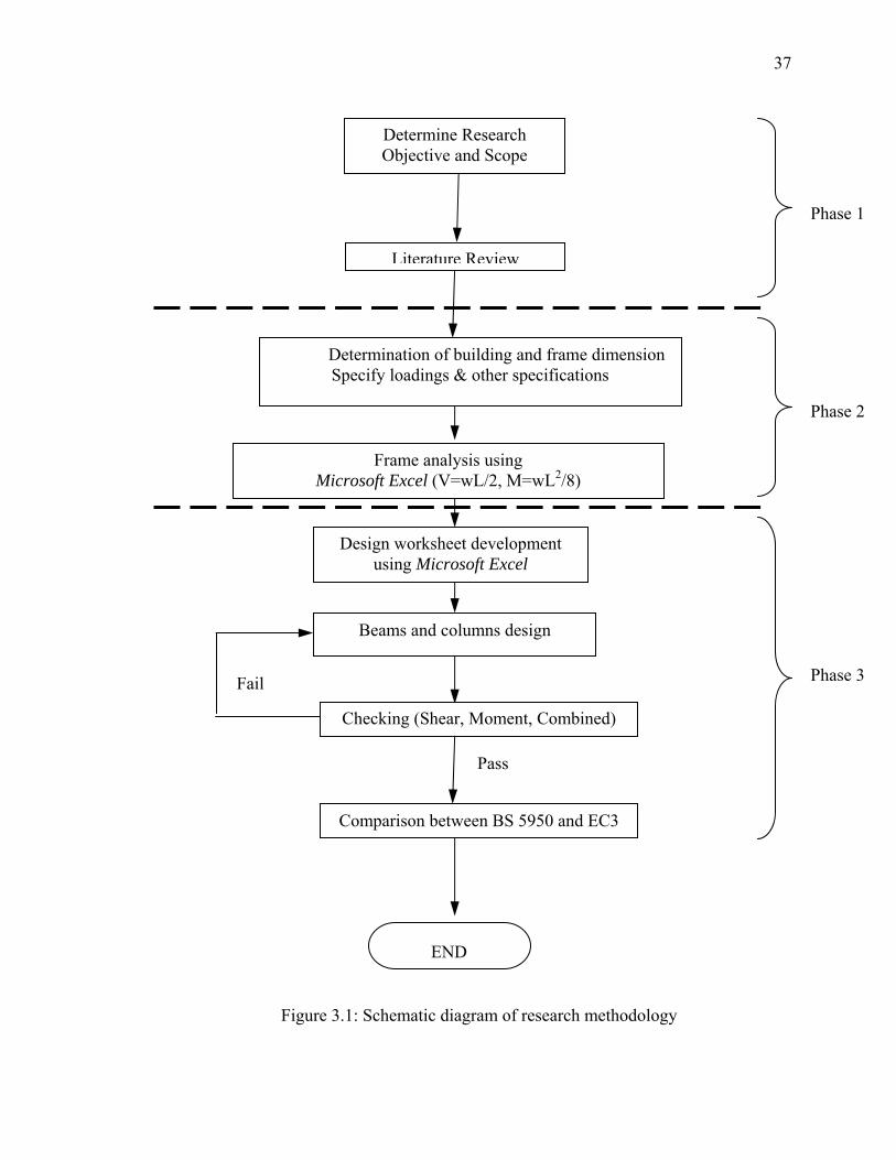
Please refer to Figure 3.1 for the flowchart of the methodology of this study.
35
3.2 Structural Analysis with Microsoft Excel Worksheets
The structural analysis of the building frame will be carried out by using
Microsoft Excel worksheets. As the scope of this study is limited at simple construction,
the use of advanced structural analysis software is not needed.
Sections 3.4 to 3.8 discuss in detail all the specifications and necessary data for
the analysis of the multi-storey braced frame. Different factors of safety with reference
to BS 5950 and EC3 are defined respectively.
Simple construction allows the connection of beam-to-column to be pinned
jointed. Therefore, only beam shear forces will be transferred to the structural column.
End moments are zero. Calculation of bending moment, M and shear force, V are based
on simply-supported condition, that is
M = wL2 / 8
V = wL / 2
where w is the uniform distributed load and L the beam span.
Please refer to Appendices A1 and A2 for the analysis worksheets created for the
purpose of calculating shear force and bending moment values based on the
requirements of different safety factors of both codes.
36
3.3 Beam and Column Design with Microsoft Excel Worksheets
The design of beam and column is calculated with Microsoft Excel software. The
Microsoft Excel software is used for its features that allow continual and repeated
calculations using values calculated in every cell of the worksheet. Several trial and
error calculations can be used to cut down on the calculation time needed as well as
prevent calculation error.
Furthermore, Microsoft Excel worksheets will show the calculation steps in a
clear and fair manner. The method of design using BS 5950 will be based on the work
example drawn by Heywood (2003). Meanwhile, the method of design using EC3 will
be based on the work example drawn by Narayanan et. al. (1995).
Please refer to Appendices B1 to C2 for the calculation worksheets created for
the purpose of the design of structural beam and column of both design codes.
37
Determine Research Objective and Scope
Frame analysis using Microsoft Excel (V=wL/2, M=wL2/8)
Determination of building and frame dimension Specify loadings & other specifications
Design worksheet development using Microsoft Excel
Beams and columns design
Pass
Literature Review
Checking (Shear, Moment, Combined)
END
Fail
Comparison between BS 5950 and EC3
Phase 1
Phase 2
Phase 3
Figure 3.1: Schematic diagram of research methodology
38
3.4 Structural Layout & Specifications
3.4.1 Structural Layout
In order to make comparisons of the design of braced steel frame between BS
5950-1: 2000 and Eurocode 3, a parametric study for the design of multi-storey braced
frames is carried out.
The number of storey of the frame is set at four (4). In plan view, the 4-storey
frame consists of four (4) bays; in total, there will be three (3) numbers of 4-storey
frames. 4th storey is roof while the rest will serve as normal floors. Each of the frame’s
longitudinal length is 6m. Two (2) lengths of bay width will be used in the analysis –
6m and 9m respectively.
The storey height will be 5m from ground floor to first floor; whereas for other
floors (1st to 2nd, 2nd to 3rd, 3rd to roof), the storey height will be 4m.
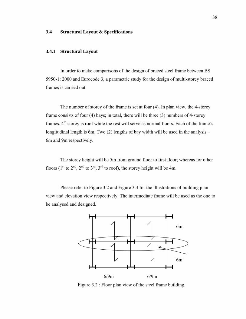
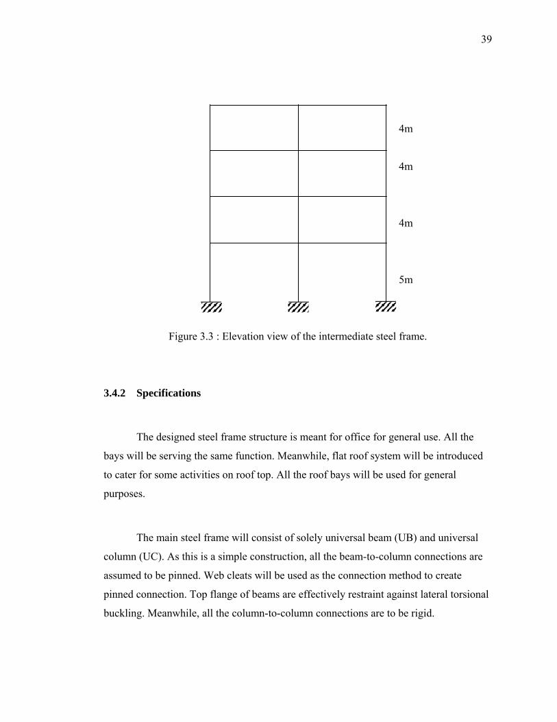
Please refer to Figure 3.2 and Figure 3.3 for the illustrations of building plan
view and elevation view respectively. The intermediate frame will be used as the one to
be analysed and designed.
6m
6m
6/9m 6/9m
Figure 3.2 : Floor plan view of the steel frame building.
39
4m
4m
4m
5m
Figure 3.3 : Elevation view of the intermediate steel frame.
3.4.2 Specifications
The designed steel frame structure is meant for office for general use. All the
bays will be serving the same function. Meanwhile, flat roof system will be introduced
to cater for some activities on roof top. All the roof bays will be used for general
purposes.
The main steel frame will consist of solely universal beam (UB) and universal
column (UC). As this is a simple construction, all the beam-to-column connections are
assumed to be pinned. Web cleats will be used as the connection method to create
pinned connection. Top flange of beams are effectively restraint against lateral torsional
buckling. Meanwhile, all the column-to-column connections are to be rigid.
40
Precast concrete flooring system will be introduced to this project. The type of
precast flooring system to be used will be solid precast floor panel. Therefore, all floors
will be of one-way slab. Consequently, each bay will contribute half of the load
intensity to the intermediate frame.
The steel frame is assumed to be laterally braced. Therefore, wind load
(horizontal load) will not be considered in the design. Only gravitational loads will be
considered in this project.
3.5 Loadings
Section 2.2.3 of Concise Eurocode 3 (C-EC3) states that the characteristic values
of imposed floor load and imposed roof load must be obtained from Part 1 and Part 3 of
BS 6399 respectively. Therefore, all the values of imposed loads of both BS 5950 and
EC3 design will be based on BS 6399.
For imposed roof load, section 6.2 (Flat roofs) states that, for a flat roof with
access available for cleaning, repair and other general purposes, a uniform load intensity
of 1.5kN/m2 is appropriate. In this design, this value will be adopted. Meanwhile, Table
8 (Offices occupancy class) states that the intensity of distributed load of offices for
general use will be 2.5kN/m2. This value will be used as this frame model is meant for a
general office usage. Multiplying by 6m (3m apiece from either side of the bay) will
result in 9kN/m and 15kN/m of load intensity on roof beam and floor beam respectively.
For precast floor selfweight, precast solid floor panel of 100mm thick was
selected for flat roof. Meanwhile, 125mm think floor panel will be used for other floors.
Weight of concrete is given by 24kN/m3. Multiplying the thickness of the slabs, the
intensity of slab selfweight will be 2.4kN/m2 and 3.0kN/m2 respectively.
41
The finishes on the flat roof will be waterproofing membrane and decorative
screed. For other floors, a selection of floor carpets and ceramic tiles will be used,
depending on the interior designer’s intention. A general load intensity of 1.0kN/m2 for
finishes (superimposed dead load) on all floors will be assumed.
Combining the superimposed dead load with selfweight, the total dead load
intensity for roof and floor slabs are 3.4kN/m2 and 4kN/m2 respectively. Multiplying by
6m (3m apiece from either side of the bay) will result in kN/m and 24kN/m of load
intensity on roof beam and floor beam respectively.
3.6 Factor of Safety
Section 2.4.1.2 “Buildings without cranes” of BS 5950 states that, in the design
of buildings not subject to loads from cranes, the principal combination of loads that
should be taken into account will be load combination 1 – Dead load and imposed
gravity loads. Partial safety factors for loads, γf should be taken as 1.4 for dead load, and
1.6 for imposed load.
In EC3, permanent actions G include dead loads such as self-weight of structure,
finishes and fittings. Meanwhile, variable actions Q include live loads such as imposed
load. From Table 2.1, for normal design situations, partial safety factors, γF for dead
load, γG is given by 1,35. Meanwhile, for imposed floor load, γQ is given by 1,5.
Partial safety factor for resistance of Class 1, 2 or 3 cross-section, γM0, is given
by 1,05. Partial safety factor for resistance of Class 4 cross-section, γM1, is given by 1,05
as well. The factor γM0 is used where the failure mode is plasticity or yielding. The
42
factor γM1 is used where the failure mode is buckling – including local buckling, which
governs the resistance of a Class 4 (slender) cross-section.
3.7 Categories
In this project, in order to justify the effect of design strength of a steel member
on the strength of a steel member, two (2) types of steel grade will be used, namely S
275 (or Fe 430 as identified in EC3) and S 355 (or Fe 510 as identified in EC3).
In BS 5950, design strength py is decided by the thickness of the thickest
element of the cross-section (for rolled sections). For steel grade S 275, py is 275N/mm2
for thickness less than or equal to 16mm and 265N/mm2 for thickness larger but less
than or equal to 40mm. For steel grade S 355, in the meantime, py is 355N/mm2 and
345N/mm2 respectively for the same limits of thickness.
3.1.2 “Material properties for hot rolled steel” (C-EC3) limits thickness of flange
to less than or equal to 40mm for nominal yield strength fy of 275N/mm2 and larger but
less than or equal to 100mm for fy of 255N/mm2. Meanwhile, for Fe 510, fy is
355N/mm2 and 335N/mm2 respectively for the same thickness limits.
3.8 Structural Analysis of Braced Frame
3.8.1 Load Combination
This section describes the structural analysis of the steel frame. According to BS
5950, the load combination will be 1.4 times total dead load plus 1.6 times total imposed
43
load (1.4DL + 1.6LL). For the roof, the resultant load combination, w, will be 48kN/m.
For all other floors, the w will be 62.64kN/m.
According to EC3, the load combination will be 1.35 times total dead load plus
1.5 times total imposed load (1,35DL + 1,5LL). For the roof, the resultant load
combination, w, will be 45.9kN/m. For all other floors, the w will be 59.76kN/m.
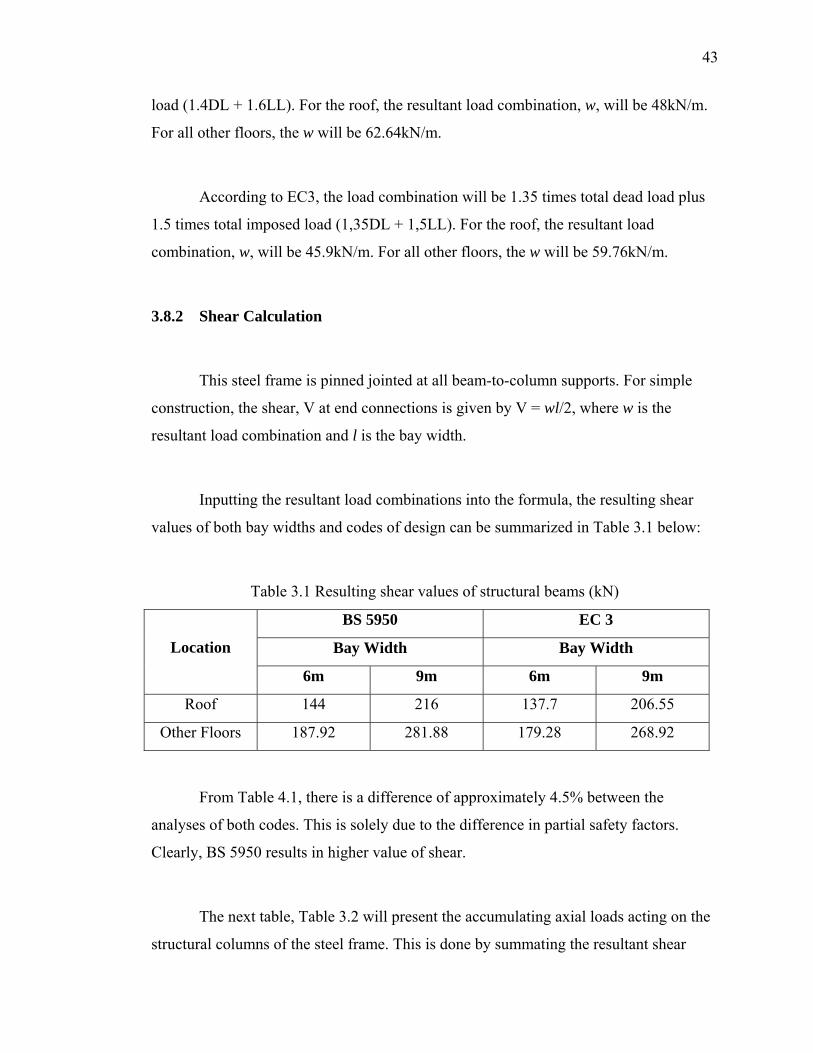
3.8.2 Shear Calculation
This steel frame is pinned jointed at all beam-to-column supports. For simple
construction, the shear, V at end connections is given by V = wl/2, where w is the
resultant load combination and l is the bay width.
Inputting the resultant load combinations into the formula, the resulting shear
values of both bay widths and codes of design can be summarized in Table 3.1 below:
Table 3.1 Resulting shear values of structural beams (kN)
BS 5950 EC 3
Bay Width Bay Width Location
6m 9m 6m 9m
Roof 144 216 137.7 206.55
Other Floors 187.92 281.88 179.28 268.92
From Table 4.1, there is a difference of approximately 4.5% between the
analyses of both codes. This is solely due to the difference in partial safety factors.
Clearly, BS 5950 results in higher value of shear.
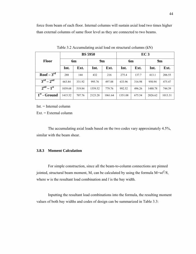
The next table, Table 3.2 will present the accumulating axial loads acting on the
structural columns of the steel frame. This is done by summating the resultant shear
44
force from beam of each floor. Internal columns will sustain axial load two times higher
than external columns of same floor level as they are connected to two beams.
Table 3.2 Accumulating axial load on structural columns (kN)
BS 5950 EC 3
6m 9m 6m 9m Floor
Int. Ext. Int. Ext. Int. Ext. Int. Ext.
Roof – 3rd 288 144 432 216 275.4 137.7 413.1 206.55
3rd – 2nd 663.84 331.92 995.76 497.88 633.96 316.98 950.94 475.47
2nd – 1st 1039.68 519.84 1559.52 779.76 992.52 496.26 1488.78 744.39
1st - Ground 1415.52 707.76 2123.28 1061.64 1351.08 675.54 2026.62 1013.31
Int. = Internal column
Ext. = External column
The accumulating axial loads based on the two codes vary approximately 4.5%,
similar with the beam shear.
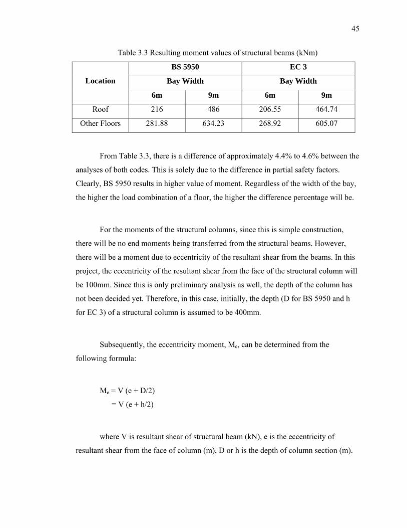
3.8.3 Moment Calculation
For simple construction, since all the beam-to-column connections are pinned
jointed, structural beam moment, M, can be calculated by using the formula M=wl2/8,
where w is the resultant load combination and l is the bay width.
Inputting the resultant load combinations into the formula, the resulting moment
values of both bay widths and codes of design can be summarized in Table 3.3:
45
Table 3.3 Resulting moment values of structural beams (kNm)
BS 5950 EC 3
Bay Width Bay Width Location
6m 9m 6m 9m
Roof 216 486 206.55 464.74
Other Floors 281.88 634.23 268.92 605.07
From Table 3.3, there is a difference of approximately 4.4% to 4.6% between the
analyses of both codes. This is solely due to the difference in partial safety factors.
Clearly, BS 5950 results in higher value of moment. Regardless of the width of the bay,
the higher the load combination of a floor, the higher the difference percentage will be.
For the moments of the structural columns, since this is simple construction,
there will be no end moments being transferred from the structural beams. However,
there will be a moment due to eccentricity of the resultant shear from the beams. In this
project, the eccentricity of the resultant shear from the face of the structural column will
be 100mm. Since this is only preliminary analysis as well, the depth of the column has
not been decided yet. Therefore, in this case, initially, the depth (D for BS 5950 and h
for EC 3) of a structural column is assumed to be 400mm.
Subsequently, the eccentricity moment, Me, can be determined from the
following formula:
Me = V (e + D/2)
= V (e + h/2)
where V is resultant shear of structural beam (kN), e is the eccentricity of
resultant shear from the face of column (m), D or h is the depth of column section (m).
46
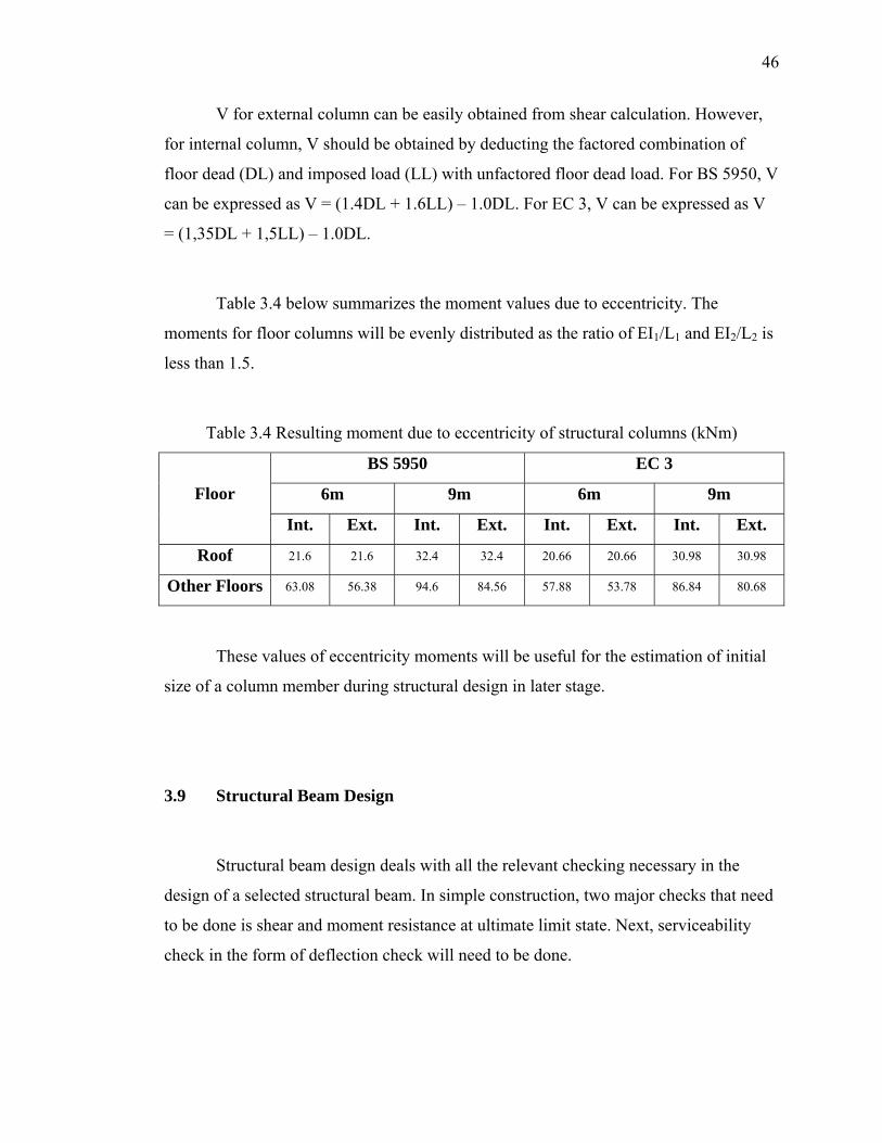
V for external column can be easily obtained from shear calculation. However,
for internal column, V should be obtained by deducting the factored combination of
floor dead (DL) and imposed load (LL) with unfactored floor dead load. For BS 5950, V
can be expressed as V = (1.4DL + 1.6LL) – 1.0DL. For EC 3, V can be expressed as V
= (1,35DL + 1,5LL) – 1.0DL.
Table 3.4 below summarizes the moment values due to eccentricity. The
moments for floor columns will be evenly distributed as the ratio of EI1/L1 and EI2/L2 is
less than 1.5.
Table 3.4 Resulting moment due to eccentricity of structural columns (kNm)
BS 5950 EC 3
6m 9m 6m 9m Floor
Int. Ext. Int. Ext. Int. Ext. Int. Ext.
Roof 21.6 21.6 32.4 32.4 20.66 20.66 30.98 30.98
Other Floors 63.08 56.38 94.6 84.56 57.88 53.78 86.84 80.68
These values of eccentricity moments will be useful for the estimation of initial
size of a column member during structural design in later stage.
3.9 Structural Beam Design
Structural beam design deals with all the relevant checking necessary in the
design of a selected structural beam. In simple construction, two major checks that need
to be done is shear and moment resistance at ultimate limit state. Next, serviceability
check in the form of deflection check will need to be done.
47
The sub-sections next will show one design example which is the floor beam of
length 6m and of steel grade S 275 (Fe 430).
3.9.1 BS 5950
In simple construction, necessary checks for ultimate limit state will be shear
buckling, shear capacity, moment capacity and web bearing capacity. The shear and
moment value for this particular floor beam is 187.92kN and 281.88kNm.
From the section table for universal beam, the sections are rearranged in
ascending form, first the mass (kg/m) and then the plastic modulus Sx (cm3). The
moment will then be divided by the design strength py to obtain an estimated minimum
plastic modulus value necessary in the design.
Sx = M / py
= 281.88 x 10³ / 275
= 1025cm3
From the rearranged table, UB section 457x152x60 is chosen. This is selected to
give a suitable moment capacity. The size will then be checked to ensure suitability in
all other aspects.
From the section table, the properties of the UB chosen are as follows: Mass =
59.8kg/m; Depth, D = 454.6mm; Width, B = 152.9mm; Web thickness, t = 8.1mm;
Flange thickness, T = 13.3mm; Depth between fillets, d = 407.6mm; Plastic modulus, Sx
= 1290cm3; Elastic modulus, Zx = 1120cm3; b/T = 6.99; d/t = 50.3.
ε = √(275/py)
= √(275/275)
48
= 1.0
Sectional classification is based on Table 11 of BS 5950. Actual b/T = 5.75,
which is smaller than 9ε = 9.0. This is the limit for Class 1 plastic section. Therefore,
flange is Class 1 plastic section. Meanwhile, actual d/t = 50.3. For web of I-section,
where neutral axis is at mid-depth, the limiting value for Class 1 plastic section is 80ε =
80.0. Actual d/t did not exceed 80.0. Therefore, web is Class 1 plastic section. Since
both flange and web are plastic, this section is Class 1 plastic section.
Next, clause 4.4.5 states that if the d/t ratio exceeds 70ε for a rolled section,
shear buckling resistance should be checked. Since actually d/t < 70.0 in this design,
therefore, shear buckling needs not be checked.
After clause 4.4.5 is checked, section 4.2.3 “Shear capacity” is checked. Shear
capacity, Pv = 0.6pyAv, where Av = tD for a rolled I-section.
Av = 8.1 x 454.6 = 3682.26mm2
Pv = 0.6 x 275 x 3682.26 x 10-3
= 607.57kN
> Fv = 187.92kN
Therefore, shear capacity is adequate.
Next, section 4.2.5 “Moment capacity, Mc” is checked.
0.6Pv = 0.6 x 607.57
= 364.54kN > Fv
Therefore, it is low shear. For class 1 plastic cross-section, Mc = pySx.
Mc = 275 x 1290 x 10-3
49
= 354.75kNm
To avoid irreversible deformation under serviceability loads, Mc should be
limited to 1.2pyZx.
1.2pyZx = 1.2 x 275 x 1120 x 10-3
= 369.6kNm > Mc, therefore, OK.
M = 281.88kNm from analysis
< Mc = 354.75kNm
Therefore, moment capacity is adequate.
To prevent crushing of the web due to forces applied through a flange, section
4.5.2 “Bearing capacity of web” is checked. If Fv exceeds Pbw, bearing capacity of web,
bearing stiffener should be provided.
Pbw = (b1 + nk)tpyw
r = 10.2mm
b1 = t + 1.6r + 2T (Figure 13)
= 8.1 + 1.6 x 10.2 + 2 x 13.3
= 51.02mm
k = T + r
= 13.3 + 10.2
= 23.5mm
At support, n = 2 + 0.6be/k, be = 0, n = 2
b1 + nk = 98.02mm
Pbw = 98.02 x 8.1 x 275 x 10-3
= 218.34kN
> Fv = 187.92kN
50
Therefore, the bearing capacity at support is adequate.
After necessary ultimate limit state checks have been done, the serviceability
limit state check (Section 2.5) should be conducted. This is done in the form of
deflection check. Generally, the serviceability load should be taken as the unfactored
specified value. Therefore, only unfactored imposed load shall be used to calculate the
deflection.
w = 15kN/m for floors.
L = 6.0m
E = 205kN/mm2
I = 25500cm4
The formula for calculating exact deflection, δ, is given by
δ = 5wL4 / 384EI
= 5 x 15 x 64 x 105 / 384 x 205 x 25500
= 4.84mm
Table 8 (Suggested limits for calculated deflections) suggests that for “beams
carrying plaster or other brittle finish), the vertical deflection limit should be L/360. In
this case,
δlim = 6000 / 360
= 16.67mm
> δ
Therefore, the deflection is satisfactory. The section is adequate. This calculation
is repeated for different sections to determine the suitable section which has the minimal
mass per length. However, it should also satisfy all the required criteria in the ultimate
limit state check.
51
This section satisfied all the required criteria in both ultimate and serviceability
limit state check. Therefore, it is adequate to be used.
3.9.2 EC 3
In simple construction, necessary checks for ultimate limit state will be shear
buckling, shear capacity, moment capacity, lateral torsional buckling, resistance of web
to crushing, crippling and buckling. The shear and moment value for this particular floor
beam is 179.28kN and 268.92kNm.
From the section table for universal beam, the sections are rearranged in
ascending form, first the mass (kg/m) and then the plastic modulus Wpl.y (cm3). The
moment will then be divided by the design strength py to obtain an estimated minimum
plastic modulus value necessary in the design.
Wpl.y = M / py
= 268.92 x 10³ / 275
= 977.9cm3
From the rearranged table, UB section 406x178x54 is chosen. This is selected to
give a suitable moment capacity. The size will then be checked to ensure suitability in
all other aspects.
From the section table, the properties of the UB chosen are as follows: Mass =
54kg/m; Depth, h = 402,6mm; Width, b = 177,6mm; Web thickness, tw = 7,6mm;
Flange thickness, tf = 10,9mm; Depth between fillets, d = 360,4mm; Plastic modulus,
Wpl.y = 1051cm3; Elastic modulus, Wel.y = 927cm3; Shear area, Av = 32,9cm2; Area of
52
section, A = 68,6cm2; Second moment of area, Iy = 18670cm4; iLT = 4,36cm; aLT =
131cm; c/tf = 8,15; d/tw = 47,4.
Before checks are done for ultimate limit states, section classification is a must.
Based on Table 3.1, tf = 10,9mm. tf ≤ 40mm. For S275 (Fe 430), yield strength, fy =
275N/mm2 and ultimate tensile strength, fu = 430N/mm2. These values must be adopted
as characteristic values in calculations. From Table 5.6(a), for “outstand element of
compression flange, flange subject to compression only”, limiting c/tf ratio (c is half of b)
is 9,2 for Class 1 elements. For “web subject to bending, neutral axis at mid depth”,
limiting d/tw ratio is 66,6 for Class 1 elements.
Actual c/tf = 8,15 ≤ 9,2. Flange is Class 1 element.
Actual d/tw = 47,4 ≤ 66,6. Web is Class 1 element.
Therefore, UB section 406x178x54 is Class 1 section.
Next, section 5.5.1 “Shear resistance of cross-section” of beam is checked. The
design value of shear force, VSd from analysis at each cross-section should not exceed
the design plastic shear resistance Vpl.Rd, that is Vpl.Rd = Av(fy / √3) / γM0.
VSd = 179,28kN
γM0 = 1,05
Vpl.Rd = (32,9 x 100 x 275) / (√3 x 1,05)
= 497,48kN
> 179,28kN
Therefore, shear resistance is sufficient.
0,5Vpl.Rd = 0,5 x 497,48
= 298,49kN > VSd = 179,28kN
53
Therefore, low shear.
For low shear, section 5.5.2 “Moment resistance of cross-section with low shear”
the design value of moment MSd must not exceed the design moment resistance of the
cross-section Mc.Rd = Wpl.y fy / γM0 for Class 1 or Class 2 cross-section.
MSd = 268,92kNm
Mc.Rd = 1051 x 275 x 10-3 / 1,05
= 275,26kNm
> MSd
Therefore, the moment capacity is sufficient.
The beam is fully restrained, not susceptible to lateral torsional buckling.
Therefore, section 5.5.5 “Lateral-torsional buckling” needs not be checked.
Section 5.5.6 “Shear buckling” requires that webs must have transverse
stiffeners at the supports if d/tw is greater than 63,8 and 56,1 for steel grade Fe 430 and
Fe 510 respectively. Actual d/tw = 47,4 < 63,8. Therefore, shear buckling check is not
required.
Section 5.6 “Resistance of webs to transverse forces” requires transverse
stiffeners to be provided in any case that the design value VSd applied through a flange
to a web exceeds the smallest of the following – Crushing resistance, Ry.Rd, crippling
resistance, Ra.Rd and buckling resistance, Rb.Rd.
For crushing resistance, Ry.Rd = (ss + sy) twfyw / γM1
where at support, sy = tf(bf/tw)0,5[fyf/fyw]0,5 [1 – (γM0 σf.Ed/fyf)2]0,5
54
At support, bending moment is zero. σf.Ed = 0. γM0 = 1,05, ss = 50mm at support.
fyf = 275N/mm2.
sy = 10,9 (177,6 / 7.6)0,5
= 52.69mm
Ry.Rd = (50 + 52,69) x 7,6 x 275 x 10-3 / 1,05
= 204,4kN
For crippling resistance,
Ra.Rd = 0,5tw
2 (Efyw)0,5 [(tf/tw)0,5 + 3(tw/tf) (ss/d)] / γM1
ss/d = 50 / 360,4
= 0,14 ≤ 0,2. OK
γM1 = 1,05
E = 210kN/mm2
Ra.Rd = 0,5 x 7,62 (210000 x 275)0,5 [(10,9/7,6)0,5 + 3(7,6/10,9)(0,14)] / 1,05
= 307,8kN
For buckling resistance, Rb.Rd = βA fc A / γM1
A = beff x tw
beff = 0,5[h2 + ss2]0,5 + a + ss/2
= 0,5 [402,62 + 502]0,5 + 0 + 50/2
= 227,8mm
beff should be less than [h2 + ss2]0,5 = 405,7mm. OK.
A = 227,8 x 7,6
= 1731,28mm2
55
βA = 1
γM1 = 1,05
For ends restrained against rotation and relative lateral movement (Table 5.29),
λ = 2,5 d/t
= 2,5 x 360,4 / 7.6
= 118,6
From Table 5.13 (rolled I-section), buckling about y-y axis, curve (a) is used.
λ√βA = 118,6
λ√βA = 118, fc = 121N/mm2
λ√βA = 120, fc = 117N/mm2
By interpolation, fc = 119,8N/mm2
Rb.Rd = 1 x 119,8 x 1731,28 x 10-3 / 1,05
= 197,5kN
Ra.Rd = 307,8kN
Ry.Rd = 204,4kN
Minimum of the 3 values are 197,5kN, which is larger than VSd = 179,28kN.
Therefore, the web of the section can resist transverse forces. OK.
After necessary ultimate limit state checks have been done, the serviceability
limit state check (Section 4.2) should be conducted. This is done in the form of
deflection check. Generally, the serviceability load should be taken as the unfactored
specified value. From Figure 4.1, deflection should take into account deflection due to
both permanent loads and imposed loads.
δmax = δ1 + δ2 – δ0 (hogging δ0 = 0 at unloaded state)
w1 = 27.6kN/m for floors. (Permanent load)
56
w2 = 15kN/m for floors. (Imposed load)
L = 6.0m
E = 210kN/mm2
Iy = 18670cm4
The formula for calculating exact deflection, δ, is given by
δ = 5wL4 / 384EI
δ1 = 5 x 27,6 x 64 x 105 / 384 x 210 x 18670
= 11,88mm
δ2 = 5 x 15 x 64 x 105 / 384 x 210 x 18670
= 6,46mm
Table 4.1 (Recommended limiting values for vertical deflections) suggests that
for “floors and roofs supporting plaster or other brittle finish or non-flexible partitions”,
the vertical deflection limit should be L/350 for δ2 and L/250 for δmax. In this case,
δlim. 2 = 6000 / 350
= 17,14mm
> δ2
δlim. max = 6000 / 250
= 24mm
> δ1 + δ2 = 18,34mm
Therefore, the deflection is satisfactory. The section is adequate. This calculation
is repeated for different sections to determine the suitable section which has the minimal
mass per length. However, it should also satisfy all the required criteria in the ultimate
limit state check.
57
This section satisfied all the required criteria in both ultimate and serviceability
limit state check. Therefore, it is adequate to be used.
3.10 Structural Column Design
Structural column design deals with all the relevant checking necessary in the
design of a selected structural beam. In simple construction, apart from section
classification, two major checks that need to be done is compression and combined axial
and bending at ultimate limit state.
The sub-sections next will show one design example which is the internal
column “ground floor to 1st floor” (length 5m) of the steel frame with bay width 6m and
of steel grade S 275 (Fe 430).
3.10.1 BS 5950
In simple construction, apart from section classification, necessary checks for
ultimate limit state will be compression resistance and combined axial force and
moment. The axial force and eccentricity moment value for this particular internal
column are 1415.52kN and 63.08kNm respectively.
From the section table for universal column, the sections are rearranged in
ascending form, first the mass (kg/m) and then the plastic modulus Sx (cm3). The
moment will then be divided by the design strength py to obtain an estimated minimum
plastic modulus value necessary in the design.
Sx = M / py
58
= 63.08 x 10³ / 275
= 229.4cm3
From the rearranged table, UC section 203x203x60 is chosen. This is selected to
give a suitable moment capacity. The size will then be checked to ensure suitability in
all other aspects.
From the section table, the properties of the UC chosen are as follows: Mass =
60kg/m; Depth, D = 209.6mm; Width, B = 205.2mm; Web thickness, t = 9.3mm; Flange
thickness, T = 14.2mm; Depth between fillets, d = 160.8mm; Plastic modulus, Sx =
652cm3; Elastic modulus, Zx = 581.1cm3; Radius of gyration, rx = 8.96cm, ry = 5.19cm;
Gross area, Ag = 75.8cm2; b/T = 7.23 (b = 0.5B); d/t = 17.3.
T < 16mm, therefore, py = 275N/mm2
ε = √(275/py)
= √(275/275)
= 1.0
Sectional classification is based on Table 11 of BS 5950. Actual b/T = 7.23,
which is smaller than 9ε = 9.0. This is the limit for Class 1 plastic section (Outstand
element of compression flange). Therefore, flange is Class 1 plastic section. Meanwhile,
actual d/t = 17.3. For web of I-section under axial compression and bending, the limiting
value for Class 1 plastic section is 80ε / 1 + r1, where r1 is given by r1 = Fc / dtpy.
r1 = 1415.52 x 103 / 160.8 x 9.3 x 275
= 3.44
but -1 < r1 ≤ 1, therefore, r1 = 1
Limiting d/t value = 80 x 1 / 1 + 1
= 40
59
> Actual d/t = 17.3
Therefore, the web is Class 1 plastic section. Since both flange and web are
plastic, this section is Class 1 plastic section.
Next, based on section 4.7.2 “Slenderness” and section 4.7.3 “Effective lengths”,
and from Table 22 (Restrained in direction at one end), the effective length, LE = 0.85L
= 0.85 x 5000 = 4250mm.
λx = LEx / rx
= 4250 / 8.96 x 10
= 47.4
Next, based on section 4.7.4 “Compression resistance”, for class 1 plastic section,
compression resistance, Pc = Agpc. pc is the compressive strength determined from Table
24. For buckling about x-x axis, T < 40mm, strut curve (b) is used.
λx = 46, pc = 242N/mm2
λx = 48, pc = 239N/mm2
From interpolation,
λx = 47.4, pc = 239.9N/mm2
Pc = Agpc
= 75.8 x 100 x 239.9 x 10-3
= 1818.44kN
> Fc = 1415.52kN
Therefore, compressive resistance is adequate.
60
Next, for columns in simple construction, the beam reaction, R, is assumed to be
acting 100mm from the face of the column. From frame analysis, Mi = 63.08kNm. The
moment is distributed between the column lengths above and below 1st floor, in
proportion to the bending stiffness of each length.
For EI / L1st-2nd : EI / Lground-1st < 1.5, the moment will be equally divided.
Therefore, M = 31.54kNm.
Section 4.7.7 “Columns in simple structures”, when only nominal moments are
applied, the column should satisfy the relationship
(Fc / Pc) + (Mx / Mbs) + (My / pyZy) ≤ 1
My = 0, therefore, My / pyZy = 0
Equivalent slenderness λLT of column is given by
λLT = 0.5L / ry
= 0.5 x 5000 / 5.19 x 10
= 48.17
From Table 16 (Bending strength pb for rolled sections),
λLT = 45, pb = 250N/mm2
λLT = 50, pb = 233N/mm2
From interpolation,
λLT = 48.17, pb = 260.78N/mm2
Mb = pbSx
= 260.78 x 652 x 10-3
= 170.03kNm
61
(Fc / Pc) + (Mx / Mbs) = 1415.52 / 1818.44 + 31.54 / 170.03
= 0.96
< 1.0
Therefore, the combined resistance against axial force and eccentricity moment
is adequate. This section satisfied all the required criteria in ultimate limit state check.
Therefore, it is adequate to be used.
3.10.2 EC 3
In simple construction, apart from section classification, necessary checks for
ultimate limit state will be cross-section resistance (in the form of moment resistance)
and in-plane failure about major axis (which is a combination of axial force and
eccentricity moment). The axial force and eccentricity moment value for this particular
internal column are 1351,08kN and 57,88kNm respectively.
From the section table for universal column, the sections are rearranged in
ascending form, first the mass (kg/m) and then the plastic modulus Wpl.y (cm3). The
moment will then be divided by the design strength fy to obtain an estimated minimum
plastic modulus value necessary in the design.
Wpl.y = MSd / fy
= 57,88 x 10³ / 275
= 210,5cm3
From the rearranged table, UC section 254x254x73 is chosen. This is selected to
give a suitable moment capacity. The size will then be checked to ensure suitability in
all other aspects.
62
From the section table, the properties of the UC chosen are as follows: Mass =
73kg/m; Depth, h = 254mm; Width, b = 254mm; Web thickness, tw = 8,6mm; Flange
thickness, tf = 14,2mm; Depth between fillets, d = 200,2mm; Plastic modulus, Wpl.y =
990cm3; Elastic modulus, Wel.y = 895cm3; Radius of gyration, iy = 11,1cm, iz = 6,46cm;
Area of section, A = 92,9cm2; Shear area, Av = 25,6cm2; Second moment of area, Iy =
11370cm4; iLT = 6,86cm; aLT = 98,5cm; c/tf = 8,94 (c = 0,5b); d/tw = 23,3.
tf = 14,2mm < 40mm, therefore, fy = 275N/mm2, fu = 430N/mm2
Sectional classification is based on Table 5.6(a) of C-EC3 for Class 1 elements.
Actual c/tf = 8,94. From this table, for outstand element of compression flange (flange
subject to compression only), the limiting values of c/tf for Class 1 and 2 are 9,2 and
10,2 respectively.
Actual c/tf = 8,94 < 9,2. Therefore, flange is Class 1 element.
For web subject to bending and compression, the classification depends on the
mean web stress, σw.
For symmetric I-section of Class 1 or 2,
σw = NSd / dtw
= 1351,08 x 103 / 200,2 x 8,6
= 784,73N/mm2
Table 5.8 gives the limiting values of stress σw for Class 1 and 2 cross-sections.
From Table 5.8, with d/tw = 23,3, the web is Class 1.
Since both flange and web are plastic, this section is Class 1 section.
Next, section 5.6 “Axially loaded members with moments” will be checked.
Beforehand, from, section 5.5.1,
63
Vpl.Rd = Av(fy / √3) / γM0
= (25,6 x 102 x 275) x 10-3 / (√3 x 1,05)
= 387,1kN
Maximum applied shear load (at top of column) is
Vmax.Sd = My.Sd / L
= 57,88 x 10³ / 5000
= 11,58kN
0,5Vpl.Rd > Vmax.Sd
Therefore, the section is subject to a low shear.
From Table 5.27, n = NSd / Npl.Rd
Reduced design plastic moment, allowing for axial force, MN.Rd is such that
n < 0,1 : MNy.Rd = Mpl.y.Rd
n ≥ 0,1 : MNy.Rd = 1,11 Mpl.y.Rd (1 – n)
Npl.Rd = A fy / γM0
= 92,9 x 102 x 275 x 10-3 / 1,05
= 2433,1kN
n = 1351,08 / 2433,1
= 0,555 ≥ 0,1
Therefore, MNy.Rd = 1,11 Mpl.y.Rd (1 – n)
Mpl.y.Rd = Wpl.y fy / γM0
= 990 x 10-3 x 275 / 1,05
= 259,3kNm
MNy.Rd = 1,11 x 259,3 x (1 – 0,555)
64
= 128,1kNm
> MSd = 28,94kNm
Therefore, the moment resistance is sufficient.
Lastly, section 5.6.3.2 “Axial compression and major axis bending” states that
all members subject to axial compression NSd and major axis moment My.Sd must satisfy
the expression
(NSd / Nb.y.Rd) + (kyMy.Sd / ηMc.y.Rd) ≤ 1,0
Ly = 0,85L
= 0,85 x 5000
= 4250mm
Slenderness ratio
λy = Ly / iy
= 4250 / 11,1 x 10
= 38,3
Based on Table 5.13 “Selection of buckling curve for fc”, for buckling about y-y
axis, buckling curve (b) is used.
βA = 1
λy√βA = 38,3
tf ≤ 40mm
λy√βA = 38, fc = 250N/mm2
λy√βA = 40, fc = 248N/mm2
From interpolation,
λy√βA = 38,3, fc = 249,7N/mm2
65
Nb.y.Rd = βA fc A / γM1, γM1 = 1,05
= 1 x 249,7 x 92,9 x 102 x 10-3 / 1,05
= 2209,3kN
ky = interaction factor about yy axis
= 1,5 (Conservative value)
η = γM0 / γM1
= 1
(NSd / Nb.y.Rd) + (kyMy.Sd / ηMc.y.Rd)
= (1351,08 / 2209,3) + (1,5 x 28,94 / 1 x 128,1)
= 0,95
< 1,0
Therefore, the resistance against in-plane failure against major axis is sufficient.
This section 254x254x73 UC satisfied all the required criteria in ultimate limit state
check. Therefore, it is adequate to be used.
CHAPTER IV
RESULTS & DISCUSSIONS
The results of the structural design of the braced steel frame (beam and column)
are tabulated and compiled in the next sections. The results are arranged accordingly,
namely structural capacity, deflection, and weight of steel.
4.1 Structural Capacity
Structural capacity deals with shear and moment resistance of a particular section
chosen. Here, structural capacity is sub-divided into beam and column.
4.1.1 Structural Beam
UB sections ranging from 305x102x25 to 533x210x122 are being tabulated in
ascending form. Shear capacity and moment capacity of each section are being
calculated separately, based on steel grade S275 and S355. The results are shown in
Table 4.1 for shear capacity and Table 5.2 for moment capacity. The results based on BS
5950 and EC3 calculation are compiled together to show the difference between each
other.
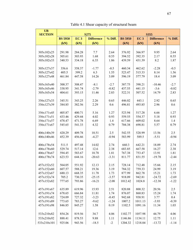
67
Table 4.1 Shear capacity of structural beam UB
SECTION S275 S355 BS 5950 EC 3 Difference % Diff. BS 5950 EC 3 Difference % Diff. (kN) (kN) (kN) (kN) (kN) (kN)
305x102x25 291.98 284.28 7.7 2.64 376.92 366.97 9.95 2.64 305x102x28 305.61 303.93 1.68 0.55 394.52 392.35 2.17 0.55 305x102x33 340.53 334.18 6.35 1.86 439.59 431.39 8.2 1.87
305x127x37 356.6 358.37 -1.77 -0.5 460.34 462.62 -2.28 -0.5 305x127x42 405.5 399.2 6.3 1.55 523.47 515.33 8.14 1.56 305x127x48 461.84 447.58 14.26 3.09 596.19 577.79 18.4 3.09
305x165x40 300.37 308.47 -8.1 -2.7 387.75 398.21 -10.46 -2.7 305x165x46 338.95 341.74 -2.79 -0.82 437.55 441.15 -3.6 -0.82 305x165x54 404.61 393.15 11.46 2.83 522.31 507.52 14.79 2.83
356x127x33 345.51 343.25 2.26 0.65 446.02 443.1 2.92 0.65 356x127x39 384.85 382.56 2.29 0.6 496.81 493.85 2.96 0.6
356x171x45 405.87 400.71 5.16 1.27 523.94 517.28 6.66 1.27 356x171x51 433.46 429.44 4.02 0.93 559.55 554.37 5.18 0.93 356x171x57 478.47 471.78 6.69 1.4 617.66 609.02 8.64 1.4 356x171x67 545.65 541.33 4.32 0.79 704.38 698.81 5.57 0.79
406x140x39 420.29 409.78 10.51 2.5 542.55 528.99 13.56 2.5 406x140x46 452.39 456.66 -4.27 -0.94 583.99 589.5 -5.51 -0.94
406x178x54 511.5 497.48 14.02 2.74 660.3 642.21 18.09 2.74 406x178x60 529.74 517.14 12.6 2.38 683.85 667.58 16.27 2.38 406x178x67 594.45 583.67 10.78 1.81 767.38 753.47 13.91 1.81 406x178x74 623.53 644.16 -20.63 -3.31 811.77 831.55 -19.78 -2.44
457x152x52 564.05 551.92 12.13 2.15 728.14 712.48 15.66 2.15 457x152x60 607.57 588.21 19.36 3.19 784.32 759.33 24.99 3.19 457x152x67 680.13 668.35 11.78 1.73 877.99 862.78 15.21 1.73 457x152x74 705.2 730.35 -25.15 -3.57 918.09 942.81 -24.72 -2.69 457x152x82 777.65 793.86 -16.21 -2.08 1012.42 1024.8 -12.38 -1.22
457x191x67 635.89 619.96 15.93 2.51 820.88 800.32 20.56 2.5 457x191x74 678.65 666.84 11.81 1.74 876.07 860.83 15.24 1.74 457x191x82 724.09 727.32 -3.23 -0.45 942.68 938.91 3.77 0.4 457x191x89 773.65 783.27 -9.62 -1.24 1007.2 1011.13 -3.93 -0.39 457x191x98 846.85 845.27 1.58 0.19 1102.5 1091.16 11.34 1.03
533x210x82 854.26 819.56 34.7 4.06 1102.77 1057.98 44.79 4.06 533x210x92 888.41 878.53 9.88 1.11 1146.86 1134.11 12.75 1.11
533x210x101 925.06 943.56 -18.5 -2 1204.32 1218.04 -13.72 -1.14
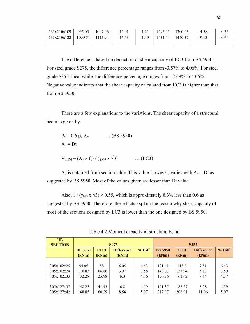
68
533x210x109 995.05 1007.06 -12.01 -1.21 1295.45 1300.03 -4.58 -0.35 533x210x122 1099.51 1115.94 -16.43 -1.49 1431.44 1440.57 -9.13 -0.64
The difference is based on deduction of shear capacity of EC3 from BS 5950.
For steel grade S275, the difference percentage ranges from -3.57% to 4.06%. For steel
grade S355, meanwhile, the difference percentage ranges from -2.69% to 4.06%.
Negative value indicates that the shear capacity calculated from EC3 is higher than that
from BS 5950.
There are a few explanations to the variations. The shear capacity of a structural
beam is given by
Pv = 0.6 py Av … (BS 5950)
Av = Dt
Vpl.Rd = (Av x fy) / (γM0 x √3) … (EC3)
Av is obtained from section table. This value, however, varies with Av = Dt as
suggested by BS 5950. Most of the values given are lesser than Dt value.
Also, 1 / (γM0 x √3) ≈ 0.55, which is approximately 8.3% less than 0.6 as
suggested by BS 5950. Therefore, these facts explain the reason why shear capacity of
most of the sections designed by EC3 is lower than the one designed by BS 5950.
Table 4.2 Moment capacity of structural beam UB
SECTION S275 S355 BS 5950 EC 3 Difference % Diff. BS 5950 EC 3 Difference % Diff. (kNm) (kNm) (kNm) (kNm) (kNm) (kNm)
305x102x25 94.05 88 6.05 6.43 121.41 113.6 7.81 6.43 305x102x28 110.83 106.86 3.97 3.58 143.07 137.94 5.13 3.59 305x102x33 132.28 125.98 6.3 4.76 170.76 162.62 8.14 4.77
305x127x37 148.23 141.43 6.8 4.59 191.35 182.57 8.78 4.59 305x127x42 168.85 160.29 8.56 5.07 217.97 206.91 11.06 5.07
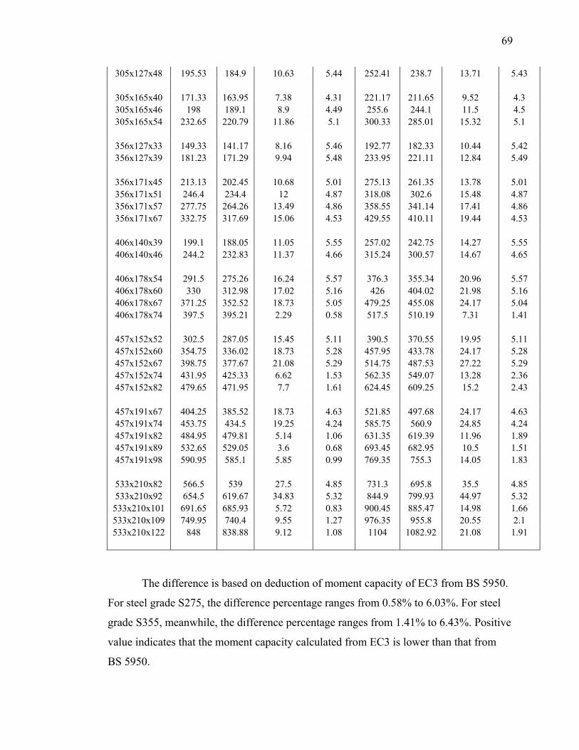
69
305x127x48 195.53 184.9 10.63 5.44 252.41 238.7 13.71 5.43
305x165x40 171.33 163.95 7.38 4.31 221.17 211.65 9.52 4.3 305x165x46 198 189.1 8.9 4.49 255.6 244.1 11.5 4.5 305x165x54 232.65 220.79 11.86 5.1 300.33 285.01 15.32 5.1
356x127x33 149.33 141.17 8.16 5.46 192.77 182.33 10.44 5.42 356x127x39 181.23 171.29 9.94 5.48 233.95 221.11 12.84 5.49
356x171x45 213.13 202.45 10.68 5.01 275.13 261.35 13.78 5.01 356x171x51 246.4 234.4 12 4.87 318.08 302.6 15.48 4.87 356x171x57 277.75 264.26 13.49 4.86 358.55 341.14 17.41 4.86 356x171x67 332.75 317.69 15.06 4.53 429.55 410.11 19.44 4.53
406x140x39 199.1 188.05 11.05 5.55 257.02 242.75 14.27 5.55 406x140x46 244.2 232.83 11.37 4.66 315.24 300.57 14.67 4.65
406x178x54 291.5 275.26 16.24 5.57 376.3 355.34 20.96 5.57 406x178x60 330 312.98 17.02 5.16 426 404.02 21.98 5.16 406x178x67 371.25 352.52 18.73 5.05 479.25 455.08 24.17 5.04 406x178x74 397.5 395.21 2.29 0.58 517.5 510.19 7.31 1.41
457x152x52 302.5 287.05 15.45 5.11 390.5 370.55 19.95 5.11 457x152x60 354.75 336.02 18.73 5.28 457.95 433.78 24.17 5.28 457x152x67 398.75 377.67 21.08 5.29 514.75 487.53 27.22 5.29 457x152x74 431.95 425.33 6.62 1.53 562.35 549.07 13.28 2.36 457x152x82 479.65 471.95 7.7 1.61 624.45 609.25 15.2 2.43
457x191x67 404.25 385.52 18.73 4.63 521.85 497.68 24.17 4.63 457x191x74 453.75 434.5 19.25 4.24 585.75 560.9 24.85 4.24 457x191x82 484.95 479.81 5.14 1.06 631.35 619.39 11.96 1.89 457x191x89 532.65 529.05 3.6 0.68 693.45 682.95 10.5 1.51 457x191x98 590.95 585.1 5.85 0.99 769.35 755.3 14.05 1.83
533x210x82 566.5 539 27.5 4.85 731.3 695.8 35.5 4.85 533x210x92 654.5 619.67 34.83 5.32 844.9 799.93 44.97 5.32
533x210x101 691.65 685.93 5.72 0.83 900.45 885.47 14.98 1.66 533x210x109 749.95 740.4 9.55 1.27 976.35 955.8 20.55 2.1 533x210x122 848 838.88 9.12 1.08 1104 1082.92 21.08 1.91
The difference is based on deduction of moment capacity of EC3 from BS 5950.
For steel grade S275, the difference percentage ranges from 0.58% to 6.03%. For steel
grade S355, meanwhile, the difference percentage ranges from 1.41% to 6.43%. Positive
value indicates that the moment capacity calculated from EC3 is lower than that from
BS 5950.
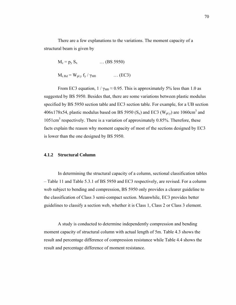
70
There are a few explanations to the variations. The moment capacity of a
structural beam is given by
Mc = py Sx … (BS 5950)
Mc.Rd = Wpl.y fy / γM0 … (EC3)
From EC3 equation, 1 / γM0 ≈ 0.95. This is approximately 5% less than 1.0 as
suggested by BS 5950. Besides that, there are some variations between plastic modulus
specified by BS 5950 section table and EC3 section table. For example, for a UB section
406x178x54, plastic modulus based on BS 5950 (Sx) and EC3 (Wpl.y) are 1060cm3 and
1051cm3 respectively. There is a variation of approximately 0.85%. Therefore, these
facts explain the reason why moment capacity of most of the sections designed by EC3
is lower than the one designed by BS 5950.
4.1.2 Structural Column
In determining the structural capacity of a column, sectional classification tables
– Table 11 and Table 5.3.1 of BS 5950 and EC3 respectively, are revised. For a column
web subject to bending and compression, BS 5950 only provides a clearer guideline to
the classification of Class 3 semi-compact section. Meanwhile, EC3 provides better
guidelines to classify a section web, whether it is Class 1, Class 2 or Class 3 element.
A study is conducted to determine independently compression and bending
moment capacity of structural column with actual length of 5m. Table 4.3 shows the
result and percentage difference of compression resistance while Table 4.4 shows the
result and percentage difference of moment resistance.
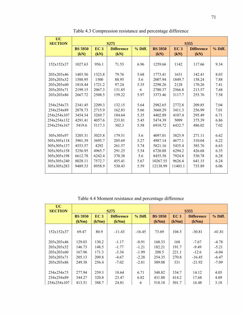
71
Table 4.3 Compression resistance and percentage difference UC
SECTION S275 S355 BS 5950 EC 3 Difference % Diff. BS 5950 EC 3 Difference % Diff. (kN) (kN) (kN) (kN) (kN) (kN)
152x152x37 1027.63 956.1 71.53 6.96 1259.66 1142 117.66 9.34
203x203x46 1403.56 1323.8 79.76 5.68 1773.41 1631 142.41 8.03 203x203x52 1588.95 1500 88.95 5.6 2007.94 1849.7 158.24 7.88 203x203x60 1818.44 1721.2 97.24 5.35 2298.26 2128 170.26 7.41 203x203x71 2199.15 2067.3 131.85 6 2780.37 2566.8 213.57 7.68 203x203x86 2667.72 2508.5 159.22 5.97 3373.46 3117.7 255.76 7.58
254x254x73 2341.45 2209.3 132.15 5.64 2982.65 2772.8 209.85 7.04 254x254x89 2878.73 2715.9 162.83 5.66 3668.29 3411.3 256.99 7.01
254x254x107 3454.34 3269.7 184.64 5.35 4402.89 4107.4 295.49 6.71 254x254x132 4291.41 4057.6 233.81 5.45 5474.39 5099 375.39 6.86 254x254x167 5419.6 5117.3 302.3 5.58 6918.72 6432.7 486.02 7.02
305x305x97 3205.31 3025.8 179.51 5.6 4097.01 3825.9 271.11 6.62
305x305x118 3901.39 3695.7 205.69 5.27 4987.14 4677.1 310.04 6.22 305x305x137 4553.57 4292 261.57 5.74 5821.16 5435.4 385.76 6.63 305x305x158 5256.95 4965.7 291.25 5.54 6720.88 6294.2 426.68 6.35 305x305x198 6612.78 6242.4 370.38 5.6 8455.58 7924.8 530.78 6.28 305x305x240 8028.11 7572.7 455.41 5.67 10267.55 9626.4 641.15 6.24 305x305x283 9489.33 8958.9 530.43 5.59 12138.99 11403.1 735.89 6.06
Table 4.4 Moment resistance and percentage difference UC
SECTION S275 S355 BS 5950 EC 3 Difference % Diff. BS 5950 EC 3 Difference % Diff. (kNm) (kNm) (kNm) (kNm) (kNm) (kNm)
152x152x37 69.47 80.9 -11.43 -16.45 73.69 104.5 -30.81 -41.81
203x203x46 129.03 130.2 -1.17 -0.91 160.33 168 -7.67 -4.78 203x203x52 146.73 148.5 -1.77 -1.21 182.21 191.7 -9.49 -5.21 203x203x60 167.96 171.3 -3.34 -1.99 208.5 221.1 -12.6 -6.04 203x203x71 205.13 209.8 -4.67 -2.28 254.35 270.8 -16.45 -6.47 203x203x86 249.38 256.4 -7.02 -2.81 309.08 331 -21.92 -7.09
254x254x73 277.94 259.3 18.64 6.71 348.82 334.7 14.12 4.05 254x254x89 344.27 320.8 23.47 6.82 431.88 414.2 17.68 4.09
254x254x107 413.51 388.7 24.81 6 518.18 501.7 16.48 3.18
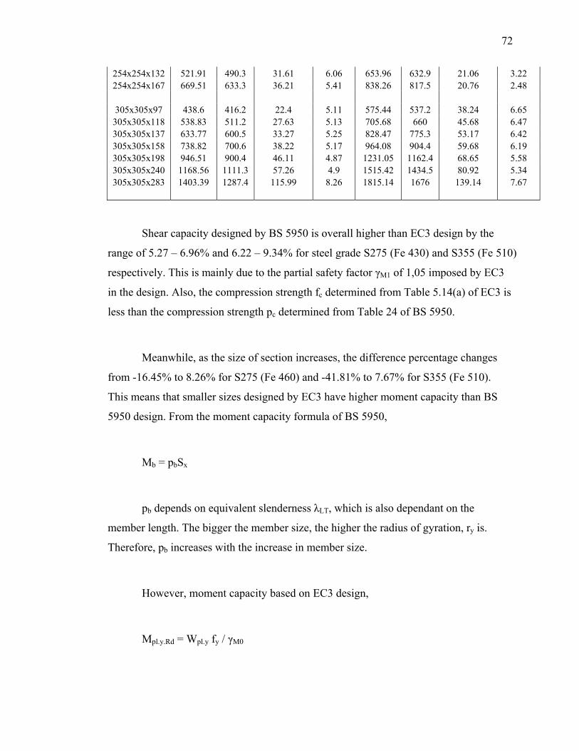
72
254x254x132 521.91 490.3 31.61 6.06 653.96 632.9 21.06 3.22 254x254x167 669.51 633.3 36.21 5.41 838.26 817.5 20.76 2.48
305x305x97 438.6 416.2 22.4 5.11 575.44 537.2 38.24 6.65
305x305x118 538.83 511.2 27.63 5.13 705.68 660 45.68 6.47 305x305x137 633.77 600.5 33.27 5.25 828.47 775.3 53.17 6.42 305x305x158 738.82 700.6 38.22 5.17 964.08 904.4 59.68 6.19 305x305x198 946.51 900.4 46.11 4.87 1231.05 1162.4 68.65 5.58 305x305x240 1168.56 1111.3 57.26 4.9 1515.42 1434.5 80.92 5.34 305x305x283 1403.39 1287.4 115.99 8.26 1815.14 1676 139.14 7.67
Shear capacity designed by BS 5950 is overall higher than EC3 design by the
range of 5.27 – 6.96% and 6.22 – 9.34% for steel grade S275 (Fe 430) and S355 (Fe 510)
respectively. This is mainly due to the partial safety factor γM1 of 1,05 imposed by EC3
in the design. Also, the compression strength fc determined from Table 5.14(a) of EC3 is
less than the compression strength pc determined from Table 24 of BS 5950.
Meanwhile, as the size of section increases, the difference percentage changes
from -16.45% to 8.26% for S275 (Fe 460) and -41.81% to 7.67% for S355 (Fe 510).
This means that smaller sizes designed by EC3 have higher moment capacity than BS
5950 design. From the moment capacity formula of BS 5950,
Mb = pbSx
pb depends on equivalent slenderness λLT, which is also dependant on the
member length. The bigger the member size, the higher the radius of gyration, ry is.
Therefore, pb increases with the increase in member size.
However, moment capacity based on EC3 design,
Mpl.y.Rd = Wpl.y fy / γM0
73
The moment capacity is not dependant on equivalent slenderness. Therefore,
when member sizes increase, eventually, the moment capacity based on EC3 is
overtaken by BS 5950 design.
4.2 Deflection
Table 4.5 shows the deflection values due to floor imposed load. In BS 5950, this
is symbolized as δ while for EC3, this is symbolized as δ2.
Table 4.5 Deflection of floor beams due to imposed load UB
SECTION L = 6.0m L = 9.0m
BS 5950 EC 3 Difference %
Diff. BS 5950 EC 3 Difference %
Diff. (δ, mm) (δ2, mm) (mm) (δ, mm) (δ2, mm) (mm)
305x102x25 27.56 27.62 -0.06 -0.22 139.53 139.83 -0.3 -0.22 305x102x28 22.99 22.16 0.83 3.61 116.41 112.19 4.22 3.63 305x102x33 19 18.54 0.46 2.42 96.17 93.86 2.31 2.4 305x127x37 17.22 16.83 0.39 2.26 87.18 85.2 1.98 2.27 305x127x42 15.06 14.77 0.29 1.93 76.23 74.79 1.44 1.89 305x127x48 12.89 12.68 0.21 1.63 65.25 64.19 1.06 1.62
305x165x40 14.53 14.1 0.43 2.96 73.54 71.36 2.18 2.96 305x165x46 12.47 12.13 0.34 2.73 63.14 61.42 1.72 2.72 305x165x54 10.55 10.31 0.24 2.27 53.43 52.2 1.23 2.3
356x127x33 14.97 14.71 0.26 1.74 75.77 74.49 1.28 1.69 356x127x39 12.11 11.93 0.18 1.49 61.28 60.42 0.86 1.4
356x171x45 10.2 9.98 0.22 2.16 51.66 50.51 1.15 2.23 356x171x51 8.76 8.51 0.25 2.85 44.33 43.09 1.24 2.8 356x171x57 7.72 7.51 0.21 2.72 39.07 38 1.07 2.74 356x171x67 6.33 6.17 0.16 2.53 32.06 31.23 0.83 2.59
406x140x39 9.88 9.71 0.17 1.72 50.01 49.17 0.84 1.68 406x140x46 7.86 7.69 0.17 2.16 39.81 38.94 0.87 2.19
406x178x54 6.6 6.46 0.14 2.12 33.43 32.68 0.75 2.24 406x178x60 5.72 5.6 0.12 2.1 28.94 28.33 0.61 2.11 406x178x67 5.08 4.95 0.13 2.56 25.72 25.08 0.64 2.49 406x178x74 4.52 4.39 0.13 2.88 22.9 22.25 0.65 2.84
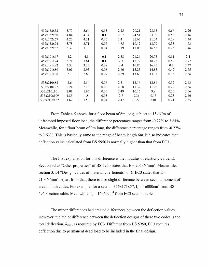
74
457x152x52 5.77 5.64 0.13 2.25 29.21 28.55 0.66 2.26 457x152x60 4.84 4.74 0.1 2.07 24.51 23.98 0.53 2.16 457x152x67 4.27 4.21 0.06 1.41 21.63 21.34 0.29 1.34 457x152x74 3.78 3.71 0.07 1.85 19.12 18.79 0.33 1.73 457x152x82 3.37 3.33 0.04 1.19 17.08 16.83 0.25 1.46
457x191x67 4.2 4.1 0.1 2.38 21.26 20.75 0.51 2.4 457x191x74 3.71 3.61 0.1 2.7 18.77 18.25 0.52 2.77 457x191x82 3.33 3.25 0.08 2.4 16.85 16.45 0.4 2.37 457x191x89 3.01 2.93 0.08 2.66 15.25 14.83 0.42 2.75 457x191x98 2.7 2.63 0.07 2.59 13.68 13.33 0.35 2.56
533x210x82 2.6 2.54 0.06 2.31 13.16 12.84 0.32 2.43 533x210x92 2.24 2.18 0.06 2.68 11.32 11.03 0.29 2.56
533x210x101 2.01 1.96 0.05 2.49 10.16 9.9 0.26 2.56 533x210x109 1.85 1.8 0.05 2.7 9.36 9.13 0.23 2.46 533x210x122 1.62 1.58 0.04 2.47 8.22 8.01 0.21 2.55
From Table 4.5 above, for a floor beam of 6m long, subject to 15kN/m of
unfactored imposed floor load, the difference percentage ranges from -0.22% to 3.61%.
Meanwhile, for a floor beam of 9m long, the difference percentage ranges from -0.22%
to 3.63%. This is basically same as the range of beam length 6m. It also indicates that
deflection value calculated from BS 5950 is normally higher than that from EC3.
The first explanation for this difference is the modulus of elasticity value, E.
Section 3.1.3 “Other properties” of BS 5950 states that E = 205kN/mm2. Meanwhile,
section 3.1.4 “Design values of material coefficients” of C-EC3 states that E =
210kN/mm2. Apart from that, there is also slight difference between second moment of
area in both codes. For example, for a section 356x171x57, Ix = 16000cm4 from BS
5950 section table. Meanwhile, Iy = 16060cm4 from EC3 section table.
The minor differences had created differences between the deflection values.
However, the major difference between the deflection designs of these two codes is the
total deflection, δmax, as required by EC3. Different from BS 5950, EC3 requires
deflection due to permanent dead load to be included in the final design.
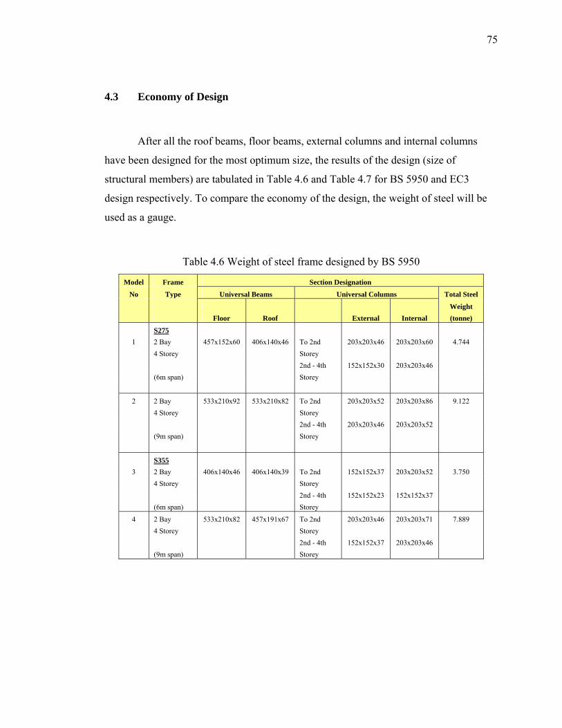
75
4.3 Economy of Design
After all the roof beams, floor beams, external columns and internal columns
have been designed for the most optimum size, the results of the design (size of
structural members) are tabulated in Table 4.6 and Table 4.7 for BS 5950 and EC3
design respectively. To compare the economy of the design, the weight of steel will be
used as a gauge.
Table 4.6 Weight of steel frame designed by BS 5950
Model Frame Section Designation
No Type Universal Beams Universal Columns Total Steel
Weight Floor Roof External Internal (tonne)
S275 1 2 Bay 457x152x60 406x140x46 To 2nd 203x203x46 203x203x60 4.744 4 Storey Storey 2nd - 4th 152x152x30 203x203x46 (6m span) Storey
2 2 Bay 533x210x92 533x210x82 To 2nd 203x203x52 203x203x86 9.122 4 Storey Storey 2nd - 4th 203x203x46 203x203x52 (9m span) Storey
S355 3 2 Bay 406x140x46 406x140x39 To 2nd 152x152x37 203x203x52 3.750 4 Storey Storey 2nd - 4th 152x152x23 152x152x37 (6m span) Storey
4 2 Bay 533x210x82 457x191x67 To 2nd 203x203x46 203x203x71 7.889 4 Storey Storey 2nd - 4th 152x152x37 203x203x46 (9m span) Storey
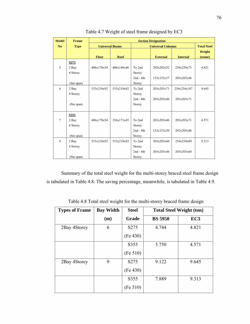
76
Table 4.7 Weight of steel frame designed by EC3
Model Frame Section Designation
No Type Universal Beams Universal Columns Total Steel
Weight Floor Roof External Internal (tonne)
S275 5 2 Bay 406x178x54 406x140x46 To 2nd 203x203x52 254x254x73 4.821 4 Storey Storey 2nd - 4th 152x152x37 203x203x46 (6m span) Storey
6 2 Bay 533x210x92 533x210x82 To 2nd 203x203x71 254x254x107 9.645 4 Storey Storey 2nd - 4th 203x203x46 203x203x71 (9m span) Storey
S355 7 2 Bay 406x178x54 356x171x45 To 2nd 203x203x46 203x203x71 4.571 4 Storey Storey 2nd - 4th 152x152x30 203x203x46 (6m span) Storey
8 2 Bay 533x210x92 533x210x82 To 2nd 203x203x60 254x254x89 9.313 4 Storey Storey 2nd - 4th 203x203x46 203x203x60 (9m span) Storey
Summary of the total steel weight for the multi-storey braced steel frame design
is tabulated in Table 4.8. The saving percentage, meanwhile, is tabulated in Table 4.9.
Table 4.8 Total steel weight for the multi-storey braced frame design
Total Steel Weight (ton) Types of Frame Bay Width
(m)
Steel
Grade BS 5950 EC3
2Bay 4Storey 6 S275
(Fe 430)
4.744 4.821
S355
(Fe 510)
3.750 4.571
2Bay 4Storey 9 S275
(Fe 430)
9.122 9.645
S355
(Fe 510)
7.889 9.313
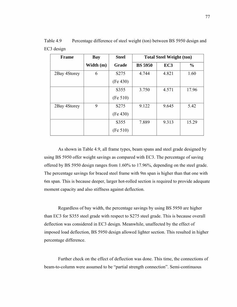
77
Table 4.9 Percentage difference of steel weight (ton) between BS 5950 design and
EC3 design
Total Steel Weight (ton) Frame Bay
Width (m)
Steel
Grade BS 5950 EC3 %
2Bay 4Storey 6 S275
(Fe 430)
4.744 4.821 1.60
S355
(Fe 510)
3.750 4.571 17.96
2Bay 4Storey 9 S275
(Fe 430)
9.122 9.645 5.42
S355
(Fe 510)
7.889 9.313 15.29
As shown in Table 4.9, all frame types, beam spans and steel grade designed by
using BS 5950 offer weight savings as compared with EC3. The percentage of saving
offered by BS 5950 design ranges from 1.60% to 17.96%, depending on the steel grade.
The percentage savings for braced steel frame with 9m span is higher than that one with
6m span. This is because deeper, larger hot-rolled section is required to provide adequate
moment capacity and also stiffness against deflection.
Regardless of bay width, the percentage savings by using BS 5950 are higher
than EC3 for S355 steel grade with respect to S275 steel grade. This is because overall
deflection was considered in EC3 design. Meanwhile, unaffected by the effect of
imposed load deflection, BS 5950 design allowed lighter section. This resulted in higher
percentage difference.
Further check on the effect of deflection was done. This time, the connections of
beam-to-column were assumed to be “partial strength connection”. Semi-continuous
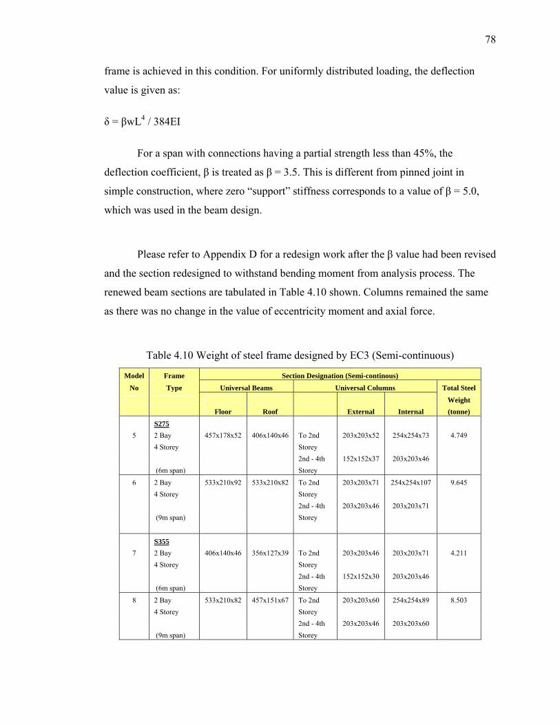
78
frame is achieved in this condition. For uniformly distributed loading, the deflection
value is given as:
δ = βwL4 / 384EI
For a span with connections having a partial strength less than 45%, the
deflection coefficient, β is treated as β = 3.5. This is different from pinned joint in
simple construction, where zero “support” stiffness corresponds to a value of β = 5.0,
which was used in the beam design.
Please refer to Appendix D for a redesign work after the β value had been revised
and the section redesigned to withstand bending moment from analysis process. The
renewed beam sections are tabulated in Table 4.10 shown. Columns remained the same
as there was no change in the value of eccentricity moment and axial force.
Table 4.10 Weight of steel frame designed by EC3 (Semi-continuous)
Model Frame Section Designation (Semi-continous)
No Type Universal Beams Universal Columns Total Steel
Weight Floor Roof External Internal (tonne)
S275 5 2 Bay 457x178x52 406x140x46 To 2nd 203x203x52 254x254x73 4.749 4 Storey Storey 2nd - 4th 152x152x37 203x203x46 (6m span) Storey
6 2 Bay 533x210x92 533x210x82 To 2nd 203x203x71 254x254x107 9.645 4 Storey Storey 2nd - 4th 203x203x46 203x203x71 (9m span) Storey
S355 7 2 Bay 406x140x46 356x127x39 To 2nd 203x203x46 203x203x71 4.211 4 Storey Storey 2nd - 4th 152x152x30 203x203x46 (6m span) Storey
8 2 Bay 533x210x82 457x151x67 To 2nd 203x203x60 254x254x89 8.503 4 Storey Storey 2nd - 4th 203x203x46 203x203x60 (9m span) Storey
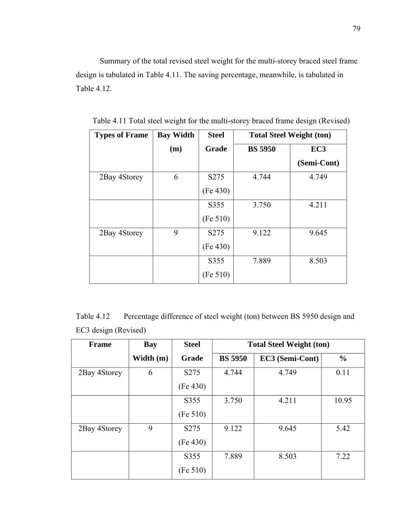
79
Summary of the total revised steel weight for the multi-storey braced steel frame
design is tabulated in Table 4.11. The saving percentage, meanwhile, is tabulated in
Table 4.12.
Table 4.11 Total steel weight for the multi-storey braced frame design (Revised)
Total Steel Weight (ton) Types of Frame Bay Width
(m)
Steel
Grade BS 5950 EC3
(Semi-Cont)
2Bay 4Storey 6 S275
(Fe 430)
4.744 4.749
S355
(Fe 510)
3.750 4.211
2Bay 4Storey 9 S275
(Fe 430)
9.122 9.645
S355
(Fe 510)
7.889 8.503
Table 4.12 Percentage difference of steel weight (ton) between BS 5950 design and
EC3 design (Revised)
Total Steel Weight (ton) Frame Bay
Width (m)
Steel
Grade BS 5950 EC3 (Semi-Cont) %
2Bay 4Storey 6 S275
(Fe 430)
4.744 4.749 0.11
S355
(Fe 510)
3.750 4.211 10.95
2Bay 4Storey 9 S275
(Fe 430)
9.122 9.645 5.42
S355
(Fe 510)
7.889 8.503 7.22
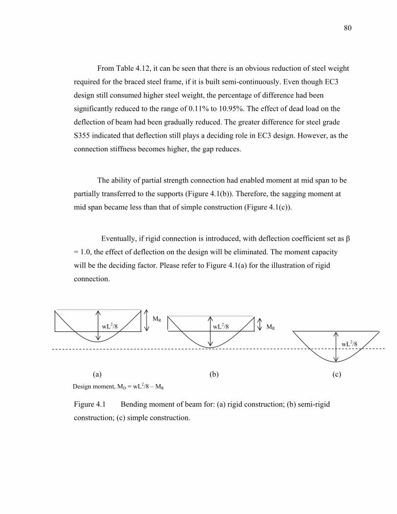
80
From Table 4.12, it can be seen that there is an obvious reduction of steel weight
required for the braced steel frame, if it is built semi-continuously. Even though EC3
design still consumed higher steel weight, the percentage of difference had been
significantly reduced to the range of 0.11% to 10.95%. The effect of dead load on the
deflection of beam had been gradually reduced. The greater difference for steel grade
S355 indicated that deflection still plays a deciding role in EC3 design. However, as the
connection stiffness becomes higher, the gap reduces.
The ability of partial strength connection had enabled moment at mid span to be
partially transferred to the supports (Figure 4.1(b)). Therefore, the sagging moment at
mid span became less than that of simple construction (Figure 4.1(c)).
Eventually, if rigid connection is introduced, with deflection coefficient set as β
= 1.0, the effect of deflection on the design will be eliminated. The moment capacity
will be the deciding factor. Please refer to Figure 4.1(a) for the illustration of rigid
connection.
wL2/8 MR
wL2/8 MR
wL2/8
(a) (b) (c) Design moment, MD = wL2/8 – MR
Figure 4.1 Bending moment of beam for: (a) rigid construction; (b) semi-rigid
construction; (c) simple construction.
CHAPTER V
CONCLUSIONS
This chapter presents the summary for the study on the comparison between BS
5950 and EC3 for the design of multi-storey braced frame. In review to the research
objectives, a summary on the results of the objectives is categorically discussed.
Suggestions of further research work are also included in this chapter.
5.1 Structural Capacity
5.1.1 Structural Beam
For the shear capacity of a structural beam, calculation based on EC3 had
reduced a member’s shear capacity of up to 4.06% with regard to BS 5950 due to the
variance between constant values of the shear capacity formula specified by both codes.
Apart from that, the difference between the approaches to obtain shear area, Av value
also caused the difference. The application of different steel grade did not contribute
greater percentage of difference between the shear capacities calculated by both codes.
Meanwhile, for the moment capacity of structural beam, calculation based on
EC3 had effectively reduced a member’s shear capacity of up to 6.43%. This is mainly
due to the application of partial safety factor, γM0 of 1,05 in the moment capacity
82
calculation required by EC3, as compared to the partial safety factor, γM of 1.0 as
suggested by BS 5950.
With the inclusion of partial safety factor, it is obvious that EC3 stresses on the
safety of a structural beam. The design of structural beam proposed by EC3 is concluded
to be safer than that by BS 5950.
5.1.2 Structural Column
In simple construction, only moments due to eccentricity will be transferred to
structural column. In comparison, axial compression is much more critical. Therefore,
only compressive resistance comparison of structural column was made.
A reduction in the range of 5.27% to 9.24% of column compressive resistance
was achieved when designing by EC3, compared with BS 5950. This comparison is
based on a structural column of 5.0m long. This is due to the implication of partial safety
factor, γM0 of 1,05 as required by EC3 design. Meanwhile, there is also a deviation in
between the compressive strength, fc and pc respectively, of both codes. From
interpolation, it was found that for a same value of λ, fc is smaller than pc.
The steel frame is assumed to be laterally braced. Therefore, wind load
(horizontal load) will not be considered in the design. Only gravitational loads will be
considered in this project.
5.2 Deflection Values
When subject to an unfactored imposed load, a structural beam will be subject to
deflection. For the same value of unfactored imposed load, EC3 design created majority
83
lower deflection values with respect to BS 5950 design. The difference ranges from -
0.22% to 3.63%. The main reason for the deviation is the difference in the specification
of modulus of elasticity, E. BS 5950 specifies 205kN/mm2 while EC3 specifies
210kN/mm2. Higher E means the elasticity of a member is higher, thus can sustain
higher load without deforming too much.
However, serviceability limit states check governs the design of EC3 as
permanent loads have to be considered in deflection check. Section 4.2.1 of EC3
provided proof to this.
Therefore, taking into account deflection due to permanent loads, the total
deflection was greater. Cross-section with higher second moment of area value, I will
have to be chosen, compared with the section chosen for BS 5950 design.
5.3 Economy
Economy aspect in this study focused on the minimum steel weight that is
needed in the construction of the braced steel frame. The total steel weight of structural
beams and columns was accumulated for comparison.
In this study, it was found that EC3 design produced braced steel frames that
require higher steel weight than the ones designed with BS 5950. For a 2-bay, 4-storey,
6m bay width steel frame, the consumption of steel for S275 (Fe 430) and S355 (Fe 510)
is 4.744 tons and 3.750 tons for BS 5950 design; and 4.821 tons and 4.571 tons for EC3
design. For a 2-bay, 4-storey, 9m bay width steel frame, the consumption of steel for
S275 (Fe 430) and S355 (Fe 510) is 9.122 tons and 7.889 tons for BS 5950 design; and
9.645 tons and 9.313 tons for EC3 design.
84
The percentages of differences are as follow:
(i) 2-bay, 4-storey, 6m bay width, S275 (Fe 430): 1.60%
(ii) 2-bay, 4-storey, 6m bay width, S355 (Fe 510): 17.96%
(iii) 2-bay, 4-storey, 9m bay width, S275 (Fe 430): 5.42%
(iv) 2-bay, 4-storey, 9m bay width, S355 (Fe 510): 15.29%
Further study was extended for the application of partial strength connection for
beam-to-column connections in EC3 design. The reduction in deflection coefficient from
5.0 to 3.5 had successfully reduced the percentage of difference between the steel
weights designed by both codes. The percentages of differences are as follow:
(i) 2-bay, 4-storey, 6m bay width, S275 (Fe 430): 0.11%
(ii) 2-bay, 4-storey, 6m bay width, S355 (Fe 510): 10.95%
(iii) 2-bay, 4-storey, 9m bay width, S275 (Fe 430): 5.42%
(iv) 2-bay, 4-storey, 9m bay width, S355 (Fe 510): 7.22%
5.4 Recommendation for Future Studies
For future studies, it is suggested that an unbraced steel frame design is
conducted to study the behavior, structural design and economic aspect based on both of
the design codes.
However, since the results of the third objective contradicted with the
background of the study (claim by Steel Construction Institute), it is recommended that
further studies to be conducted to focus on the economy aspect of EC3 with respect to
BS 5950. This study showed that steel weight did not contribute to cost saving of EC3
design.
85
REFERENCES
Charles King (2005). “Steel Design Can be Simple Using EC3.” New Steel
Construction, Vol 13 No 4, 24-27.
Steel Construction Institute (SCI) (2005). “EN 1993 Eurocode 3 – Steel.” Eurocodenews,
November 2005, Issue 3, 4.
Taylor J.C. (2001). “EN1993 Eurocode 3: Design of Steel Structures.” ICE Journal,
Paper 2658, 29-32.
British Standards Institution (2001). “British Standard – Structural Use of Steelwork in
Building: Part 1: Code of Practice for Design – Rolled and Welded Sections.” London:
British Standards Institution.
European Committee for Standardization (1992). “Eurocode 3: Design of Steel
Structures: Part 1.1 General Rules and Rules for Buildings.” London: European
Committee for Standardization.
Heywood M. D. & Lim J B (2003). “Steelwork design guide to BS 5950-1:2000
Volume 2: Worked examples.” Berkshire: Steel Construction Institute.
Narayanan R et. al. (1995). “Introduction to Concise Eurocode 3 (C-EC3) – with
Worked Examples.” Berkshire: Steel Construction Institute.

86
APPENDIX A1
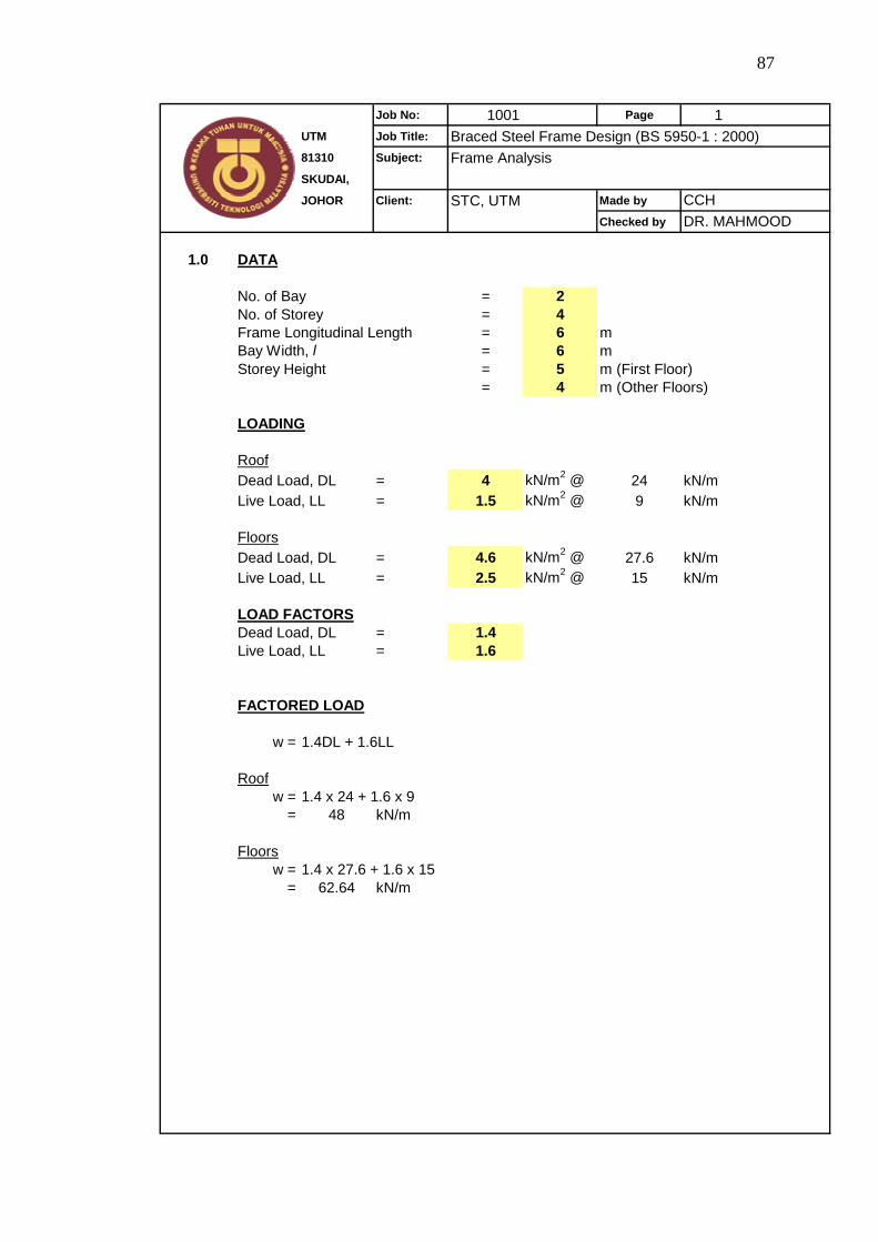
87
Job No: 1001 Page 1UTM Job Title: Braced Steel Frame Design (BS 5950-1 : 2000)81310 Subject: Frame AnalysisSKUDAI,
JOHOR Client: STC, UTM Made by
Checked by
1.0 DATA
= 2No. of Storey = 4Frame Longitudinal Length = 6 mBay Width, l = 6 mStorey Height = 5 m (First Floor)
= 4 m (Other Floors)
LOADING
RoofDead Load, DL = 4 kN/m2 @ 24 kN/mLive Load, LL = 1.5 kN/m2 @ 9 kN/m
FloorsDead Load, DL = 4.6 kN/m2 @ 27.6 kN/mLive Load, LL = 2.5 kN/m2 @ 15 kN/m
LOAD FACTORSDead Load, DL = 1.4Live Load, LL = 1.6
FACTORED LOAD
w = 1.4DL + 1.6LL
Roofw = 1.4 x 24 + 1.6 x 9
= 48 kN/m
Floorsw = 1.4 x 27.6 + 1.6 x 15
= 62.64 kN/m
No. of Bay
CCHDR. MAHMOOD
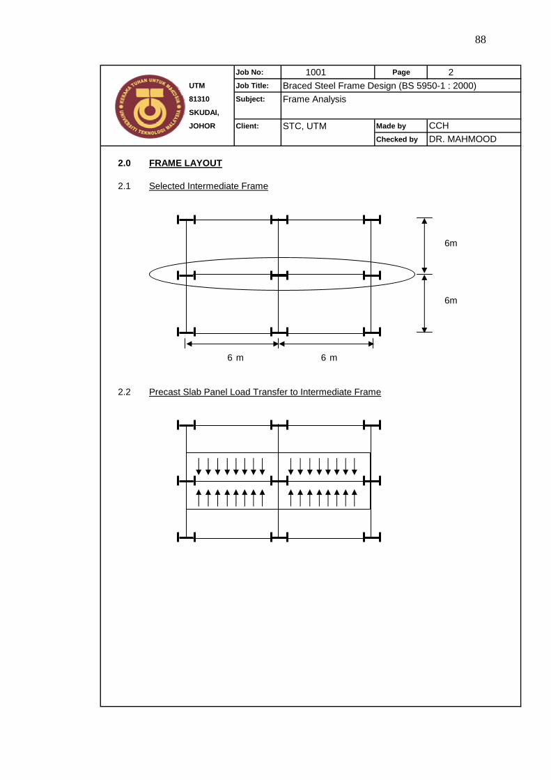
88
Job No: 1001 Page 2UTM Job Title: Braced Steel Frame Design (BS 5950-1 : 2000)81310 Subject: Frame AnalysisSKUDAI,
JOHOR Client: STC, UTM Made by
Checked by
2.0 FRAME LAYOUT
2.1 Selected Intermediate Frame
6m
6m
6 m 6 m
2.2 Precast Slab Panel Load Transfer to Intermediate Frame
CCHDR. MAHMOOD
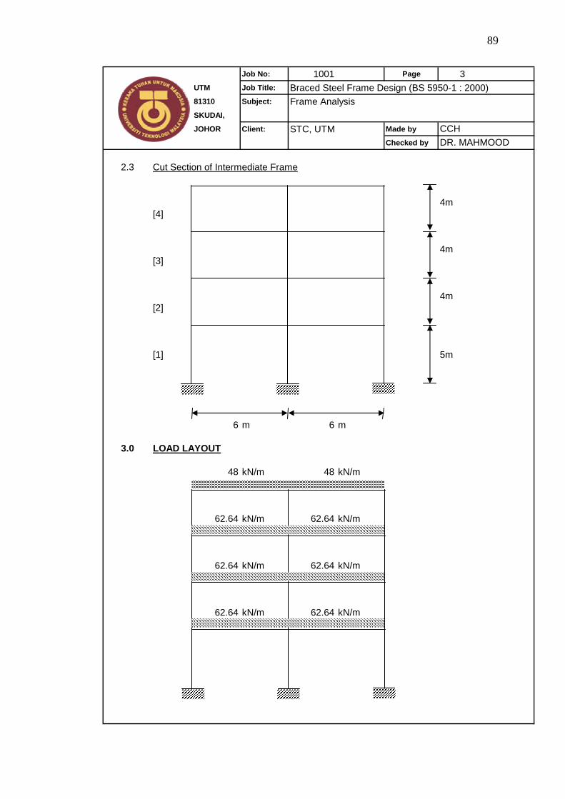
89
Job No: 1001 Page 3UTM Job Title: Braced Steel Frame Design (BS 5950-1 : 2000)81310 Subject: Frame AnalysisSKUDAI,
JOHOR Client: STC, UTM Made by
Checked by
2.3 Cut Section of Intermediate Frame
4m[4]
4m[3]
4m[2]
[1] 5m
6 m 6 m
3.0 LOAD LAYOUT
48 kN/m 48 kN/m
62.64 kN/m 62.64 kN/m
62.64 kN/m 62.64 kN/m
62.64 kN/m 62.64 kN/m
CCHDR. MAHMOOD

90
Job No: 1001 Page 4UTM Job Title: Braced Steel Frame Design (BS 5950-1 : 2000)81310 Subject: Frame AnalysisSKUDAI,
JOHOR Client: STC, UTM Made by
Checked by
4.0 LOAD CALCULATION
Frame bracingLaterally braced, horizontal load is not taken into account
Beam restraintTop flange effectively restrained against lateral torsional buckling
4.1 Beam
Moment, M = wl 2 / 8Shear, V = wl / 2
Roof beams,V = 48 x 6 / 2
= 144 kN
M = 48 x 6^2 / 8= 216 kNm
Floor beams,V = 62.64 x 6 / 2
= 187.92 kN
M = 62.64 x 6^2 / 8= 281.88 kNm
4.2 Column
Shear
ColumnInternal External
[4] 288 144[3] 663.84 331.92[2] 1039.68 519.84[1] 1415.52 707.76
Moment
External column will be subjected to eccentricity moment, contributed by beam shear.Eccentricity = 100 mm from face of column.Universal column of depth 200 mmInternal column - Moments from left and right will cancel out each other.
Shear (kN)
CCHDR. MAHMOOD
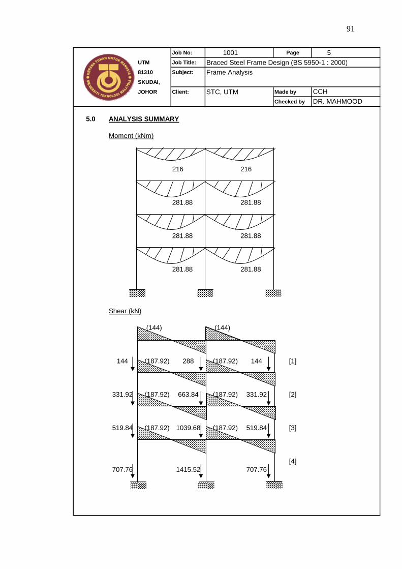
91
Job No: 1001 Page 5UTM Job Title: Braced Steel Frame Design (BS 5950-1 : 2000)81310 Subject: Frame AnalysisSKUDAI,
JOHOR Client: STC, UTM Made by
Checked by
5.0 ANALYSIS SUMMARY
Moment (kNm)
216 216
281.88 281.88
281.88 281.88
281.88 281.88
Shear (kN)
(144) (144)
144 (187.92) 288 (187.92) 144 [1]
331.92 (187.92) 663.84 (187.92) 331.92 [2]
519.84 (187.92) 1039.68 (187.92) 519.84 [3]
[4]707.76 1415.52 707.76
CCHDR. MAHMOOD
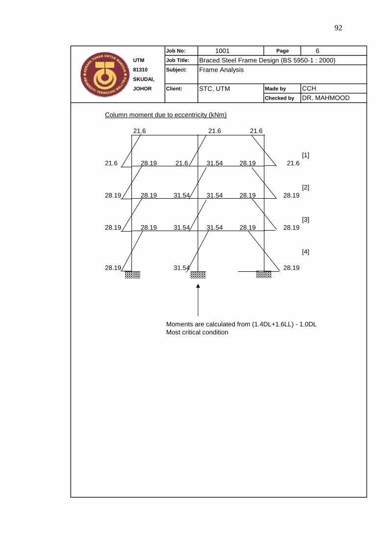
92
Job No: 1001 Page 6UTM Job Title: Braced Steel Frame Design (BS 5950-1 : 2000)81310 Subject: Frame AnalysisSKUDAI,
JOHOR Client: STC, UTM Made by
Checked by
Column moment due to eccentricity (kNm)
21.6 21.6 21.6
[1]21.6 28.19 21.6 31.54 28.19 21.6
[2]28.19 28.19 31.54 31.54 28.19 28.19
[3]28.19 28.19 31.54 31.54 28.19 28.19
[4]
28.19 31.54 28.19
Moments are calculated from (1.4DL+1.6LL) - 1.0DLMost critical condition
CCHDR. MAHMOOD

93
APPENDIX A2
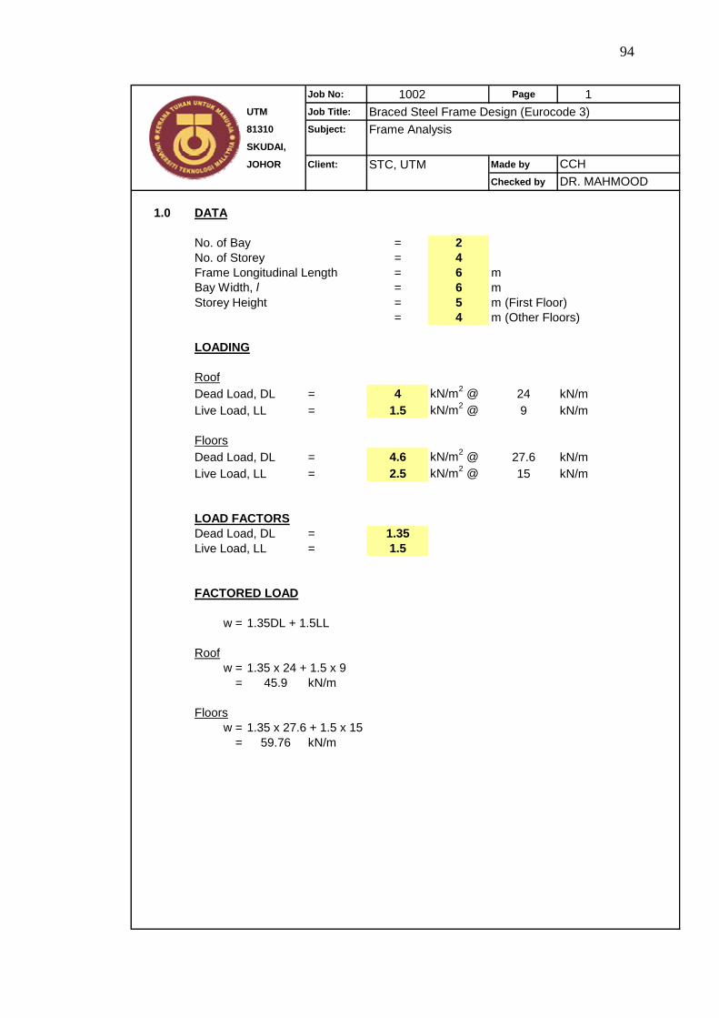
94
Job No: 1002 Page 1UTM Job Title: Braced Steel Frame Design (Eurocode 3)81310 Subject: Frame AnalysisSKUDAI,
JOHOR Client: STC, UTM Made by
Checked by
1.0 DATA
= 2No. of Storey = 4Frame Longitudinal Length = 6 mBay Width, l = 6 mStorey Height = 5 m (First Floor)
= 4 m (Other Floors)
LOADING
RoofDead Load, DL = 4 kN/m2 @ 24 kN/mLive Load, LL = 1.5 kN/m2 @ 9 kN/m
FloorsDead Load, DL = 4.6 kN/m2 @ 27.6 kN/mLive Load, LL = 2.5 kN/m2 @ 15 kN/m
LOAD FACTORSDead Load, DL = 1.35Live Load, LL = 1.5
FACTORED LOAD
w = 1.35DL + 1.5LL
Roofw = 1.35 x 24 + 1.5 x 9
= 45.9 kN/m
Floorsw = 1.35 x 27.6 + 1.5 x 15
= 59.76 kN/m
CCHDR. MAHMOOD
No. of Bay
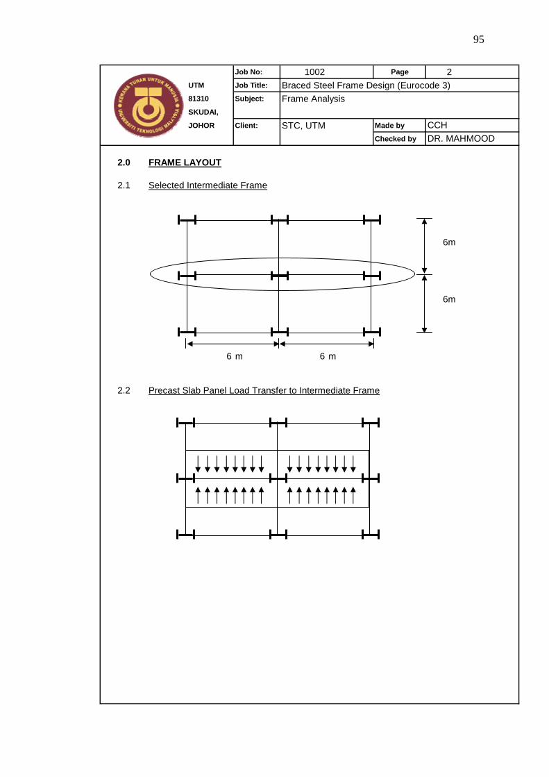
95
Job No: 1002 Page 2UTM Job Title: Braced Steel Frame Design (Eurocode 3)81310 Subject: Frame AnalysisSKUDAI,
JOHOR Client: STC, UTM Made by
Checked by
2.0 FRAME LAYOUT
2.1 Selected Intermediate Frame
6m
6m
6 m 6 m
2.2 Precast Slab Panel Load Transfer to Intermediate Frame
CCHDR. MAHMOOD
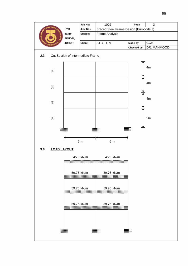
96
Job No: 1002 Page 3UTM Job Title: Braced Steel Frame Design (Eurocode 3)81310 Subject: Frame AnalysisSKUDAI,
JOHOR Client: STC, UTM Made by
Checked by
2.3 Cut Section of Intermediate Frame
4m[4]
4m[3]
4m[2]
[1] 5m
6 m 6 m
3.0 LOAD LAYOUT
45.9 kN/m 45.9 kN/m
59.76 kN/m 59.76 kN/m
59.76 kN/m 59.76 kN/m
59.76 kN/m 59.76 kN/m
CCHDR. MAHMOOD
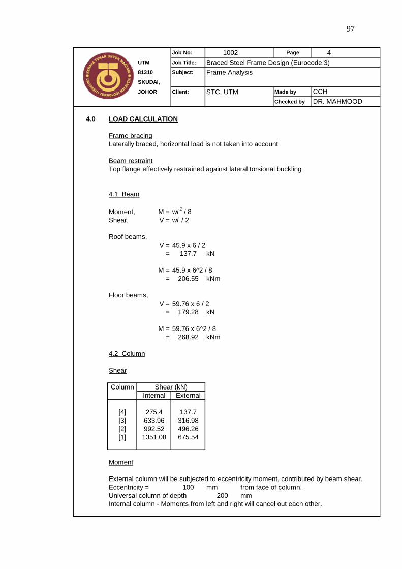
97
Job No: 1002 Page 4UTM Job Title: Braced Steel Frame Design (Eurocode 3)81310 Subject: Frame AnalysisSKUDAI,
JOHOR Client: STC, UTM Made by
Checked by
4.0 LOAD CALCULATION
Frame bracingLaterally braced, horizontal load is not taken into account
Beam restraintTop flange effectively restrained against lateral torsional buckling
4.1 Beam
Moment, M = wl 2 / 8Shear, V = wl / 2
Roof beams,V = 45.9 x 6 / 2
= 137.7 kN
M = 45.9 x 6^2 / 8= 206.55 kNm
Floor beams,V = 59.76 x 6 / 2
= 179.28 kN
M = 59.76 x 6^2 / 8= 268.92 kNm
4.2 Column
Shear
ColumnInternal External
[4] 275.4 137.7[3] 633.96 316.98[2] 992.52 496.26[1] 1351.08 675.54
Moment
External column will be subjected to eccentricity moment, contributed by beam shear.Eccentricity = 100 mm from face of column.Universal column of depth 200 mmInternal column - Moments from left and right will cancel out each other.
Shear (kN)
CCHDR. MAHMOOD
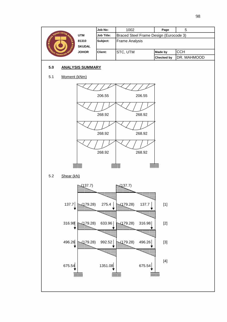
98
Job No: 1002 Page 5UTM Job Title: Braced Steel Frame Design (Eurocode 3)81310 Subject: Frame AnalysisSKUDAI,
JOHOR Client: STC, UTM Made by
Checked by
5.0 ANALYSIS SUMMARY
5.1 Moment (kNm)
206.55 206.55
268.92 268.92
268.92 268.92
268.92 268.92
5.2 Shear (kN)
(137.7) (137.7)
137.7 (179.28) 275.4 (179.28) 137.7 [1]
316.98 (179.28) 633.96 (179.28) 316.98 [2]
496.26 (179.28) 992.52 (179.28) 496.26 [3]
[4]675.54 1351.08 675.54
CCHDR. MAHMOOD
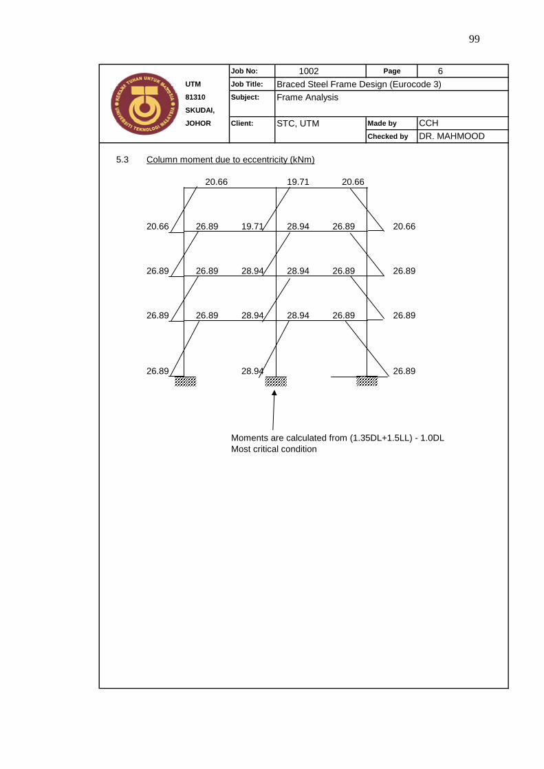
99
Job No: 1002 Page 6UTM Job Title: Braced Steel Frame Design (Eurocode 3)81310 Subject: Frame AnalysisSKUDAI,
JOHOR Client: STC, UTM Made by
Checked by
5.3 Column moment due to eccentricity (kNm)
20.66 19.71 20.66
20.66 26.89 19.71 28.94 26.89 20.66
26.89 26.89 28.94 28.94 26.89 26.89
26.89 26.89 28.94 28.94 26.89 26.89
26.89 28.94 26.89
Moments are calculated from (1.35DL+1.5LL) - 1.0DLMost critical condition
CCHDR. MAHMOOD

100
APPENDIX B1
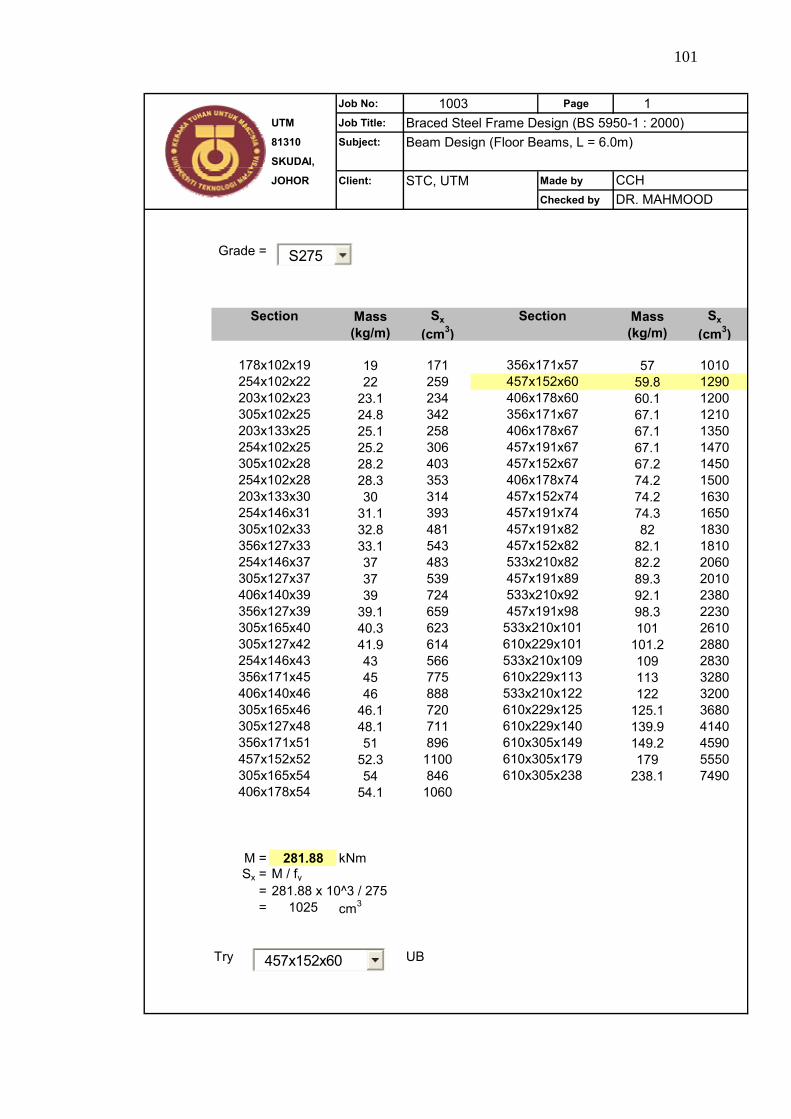
101
Job No: 1003 Page 1UTM Job Title: Braced Steel Frame Design (BS 5950-1 : 2000)81310 Subject: Beam Design (Floor Beams, L = 6.0m)SKUDAI,
JOHOR Client: STC, UTM Made by
Checked by
Grade =
Mass Sx Mass Sx(kg/m) (cm3) (kg/m) (cm3)
19 171 57 101022 259 59.8 1290
23.1 234 60.1 120024.8 342 67.1 121025.1 258 67.1 135025.2 306 67.1 147028.2 403 67.2 145028.3 353 74.2 150030 314 74.2 1630
31.1 393 74.3 165032.8 481 82 183033.1 543 82.1 181037 483 82.2 206037 539 89.3 201039 724 92.1 2380
39.1 659 98.3 223040.3 623 101 261041.9 614 101.2 288043 566 109 283045 775 113 328046 888 122 3200
46.1 720 125.1 368048.1 711 139.9 414051 896 149.2 4590
52.3 1100 179 555054 846 238.1 7490
54.1 1060
M = 281.88 kNmSx = M / fy
= 281.88 x 10^3 / 275= 1025 cm3
Try UB
610x305x179610x305x238
533x210x122610x229x125610x229x140610x305x149
533x210x101610x229x101533x210x109610x229x113
533x210x82457x191x89533x210x92457x191x98
457x152x74457x191x74457x191x82457x152x82
305x165x54406x178x54
356x171x57457x152x60406x178x60356x171x67406x178x67457x191x67457x152x67406x178x74
305x165x46305x127x48356x171x51457x152x52
305x127x42254x146x43356x171x45406x140x46
305x127x37406x140x39356x127x39305x165x40
254x102x25305x102x28254x102x28203x133x30254x146x31305x102x33356x127x33254x146x37
CCHDR. MAHMOOD
Section Section
178x102x19254x102x22203x102x23305x102x25203x133x25
457x152x60
S275
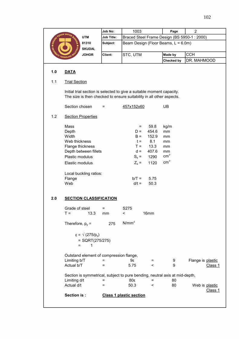
102
Job No: 1003 Page 2UTM Job Title: Braced Steel Frame Design (BS 5950-1 : 2000)81310 Subject: Beam Design (Floor Beams, L = 6.0m)SKUDAI,
JOHOR Client: STC, UTM Made by
Checked by
1.0 DATA
1.1
Initial trial section is selected to give a suitable moment capacity.The size is then checked to ensure suitability in all other aspects.
Section chosen = 457x152x60 UB
1.2 Section Properties
Mass = 59.8 kg/mDepth D = 454.6 mmWidth B = 152.9 mmWeb thickness t = 8.1 mmFlange thickness T = 13.3 mmDepth between fillets d = 407.6 mmPlastic modulus Sx = 1290 cm3
Elastic modulus Zx = 1120 cm3
Local buckling ratios:Flange b/T = 5.75Web d/t = 50.3
2.0 SECTION CLASSIFICATION
Grade of steel = S275T = 13.3 mm < 16mm
Therefore, py = 275 N/mm2
ε = √ (275/py)= SQRT(275/275)= 1
Outstand element of compression flange,Limiting b/T = 9ε = 9 Flange is plasticActual b/T = 5.75 < 9 Class 1
Section is symmetrical, subject to pure bending, neutral axis at mid-depth,Limiting d/t = 80ε = 80Actual d/t = 50.3 < 80 Web is plastic
Class 1Section is : Class 1 plastic section
CCHDR. MAHMOOD
Trial Section
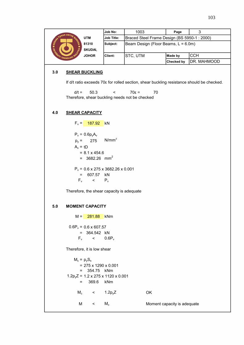
103
Job No: 1003 Page 3UTM Job Title: Braced Steel Frame Design (BS 5950-1 : 2000)81310 Subject: Beam Design (Floor Beams, L = 6.0m)SKUDAI,
JOHOR Client: STC, UTM Made by
Checked by
3.0 SHEAR BUCKLING
If d/t ratio exceeds 70ε for rolled section, shear buckling resistance should be checked.
d/t = 50.3 < 70ε = 70Therefore, shear buckling needs not be checked
4.0 SHEAR CAPACITY
Fv = 187.92 kN
Pv = 0.6pyAv
py = 275 N/mm2
Av = tD= 8.1 x 454.6= 3682.26 mm2
Pv = 0.6 x 275 x 3682.26 x 0.001= 607.57 kN
Fv < Pv
Therefore, the shear capacity is adequate
5.0 MOMENT CAPACITY
M = 281.88 kNm
0.6Pv = 0.6 x 607.57= 364.542 kN
Fv < 0.6Pv
Therefore, it is low shear
Mc = pySx
= 275 x 1290 x 0.001= 354.75 kNm
1.2pyZ = 1.2 x 275 x 1120 x 0.001= 369.6 kNm
Mc < 1.2pyZ OK
M < Mc Moment capacity is adequate
CCHDR. MAHMOOD
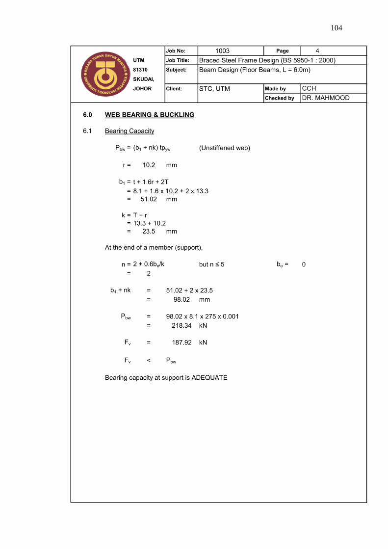
104
Job No: 1003 Page 4UTM Job Title: Braced Steel Frame Design (BS 5950-1 : 2000)81310 Subject: Beam Design (Floor Beams, L = 6.0m)SKUDAI,
JOHOR Client: STC, UTM Made by
Checked by
6.0 WEB BEARING & BUCKLING
6.1 Bearing Capacity
Pbw = (b1 + nk) tpyw (Unstiffened web)
r = 10.2 mm
b1 = t + 1.6r + 2T= 8.1 + 1.6 x 10.2 + 2 x 13.3= 51.02 mm
k = T + r= 13.3 + 10.2= 23.5 mm
At the end of a member (support),
n = 2 + 0.6be/k but n ≤ 5 be = 0= 2
b1 + nk = 51.02 + 2 x 23.5= 98.02 mm
Pbw = 98.02 x 8.1 x 275 x 0.001= 218.34 kN
Fv = 187.92 kN
Fv < Pbw
Bearing capacity at support is ADEQUATE
CCHDR. MAHMOOD
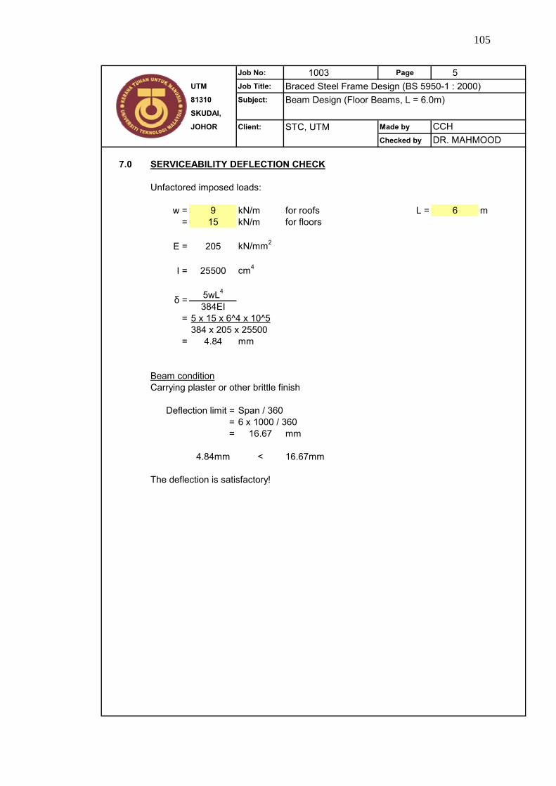
105
Job No: 1003 Page 5UTM Job Title: Braced Steel Frame Design (BS 5950-1 : 2000)81310 Subject: Beam Design (Floor Beams, L = 6.0m)SKUDAI,
JOHOR Client: STC, UTM Made by
Checked by
7.0 SERVICEABILITY DEFLECTION CHECK
Unfactored imposed loads:
w = 9 kN/m for roofs L = 6 m= 15 kN/m for floors
E = 205 kN/mm2
I = 25500 cm4
5wL4
384EI= 5 x 15 x 6^4 x 10^5
384 x 205 x 25500= 4.84 mm
Beam conditionCarrying plaster or other brittle finish
Span / 360= 6 x 1000 / 360= 16.67 mm
4.84mm < 16.67mm
The deflection is satisfactory!
CCHDR. MAHMOOD
δ =
Deflection limit =

106
APPENDIX B2
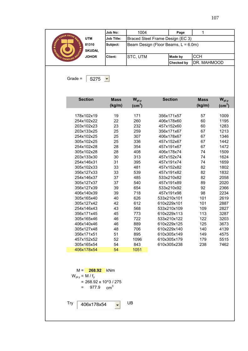
107
Job No: 1004 Page 1UTM Job Title: Braced Steel Frame Design (EC 3)81310 Subject: Beam Design (Floor Beams, L = 6.0m)SKUDAI,
JOHOR Client: STC, UTM Made by
Checked by
Grade =
Mass Wpl.y Mass Wpl.y
(kg/m) (cm3) (kg/m) (cm3)
19 171 57 100922 260 60 119523 232 60 128325 259 67 121325 307 67 134625 336 67 144228 354 67 147228 408 74 150930 313 74 162431 395 74 165933 481 82 180233 539 82 183237 485 82 205837 540 89 202039 654 92 236639 718 98 223440 626 101 261942 612 101 288743 568 109 282745 773 113 328746 722 122 320346 889 125 367348 706 140 413951 895 149 457552 1096 179 551554 843 238 746254 1051
M = 268.92 kNmWpl.y = M / fy
= 268.92 x 10^3 / 275= 977.9 cm3
Try UB
203x102x23254x102x22178x102x19
254x102x28305x102x25254x102x25203x133x25
305x102x33254x146x31203x133x30305x102x28
356x127x39305x127x37254x146x37356x127x33
254x146x43305x127x42305x165x40406x140x39
305x127x48406x140x46305x165x46356x171x45
406x178x54305x165x54457x152x52356x171x51
610x229x140610x305x149610x305x179610x305x238
533x210x109610x229x113533x210x122610x229x125
533x210x92457x191x98533x210x101610x229x101
457x152x82457x191x82533x210x82457x191x89
457x191x67406x178x74457x152x74457x191x74
457x152x60356x171x67406x178x67457x152x67
Section Section
356x171x57406x178x60
CCHDR. MAHMOOD
406x178x54
S275
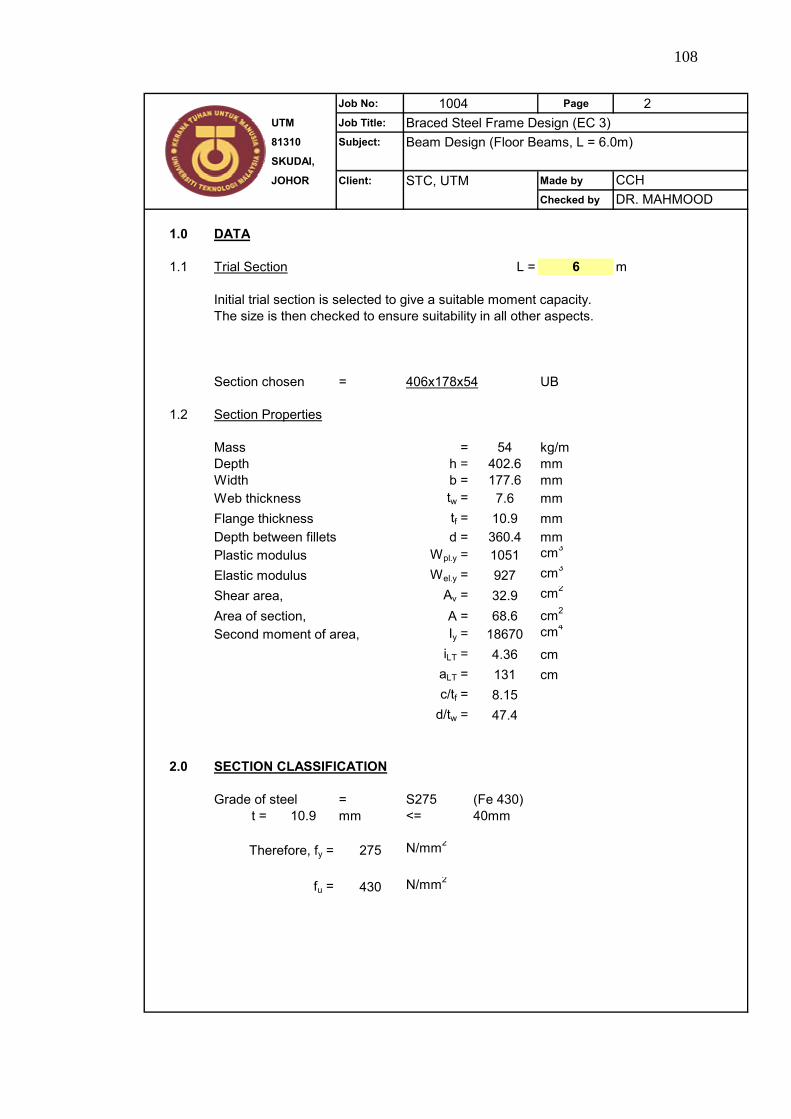
108
Job No: 1004 Page 2UTM Job Title: Braced Steel Frame Design (EC 3)81310 Subject: Beam Design (Floor Beams, L = 6.0m)SKUDAI,
JOHOR Client: STC, UTM Made by
Checked by
1.0 DATA
1.1 L = 6 m
Initial trial section is selected to give a suitable moment capacity.The size is then checked to ensure suitability in all other aspects.
Section chosen = 406x178x54 UB
1.2 Section Properties
Mass = 54 kg/mDepth h = 402.6 mmWidth b = 177.6 mmWeb thickness tw = 7.6 mmFlange thickness tf = 10.9 mmDepth between fillets d = 360.4 mmPlastic modulus Wpl.y = 1051 cm3
Elastic modulus Wel.y = 927 cm3
Shear area, Av = 32.9 cm2
Area of section, A = 68.6 cm2
Second moment of area, Iy = 18670 cm4
iLT = 4.36 cmaLT = 131 cmc/tf = 8.15
d/tw = 47.4
2.0 SECTION CLASSIFICATION
Grade of steel = S275 (Fe 430)t = 10.9 mm <= 40mm
275 N/mm2
fu = 430 N/mm2
Trial Section
Therefore, fy =
CCHDR. MAHMOOD

109
Job No: 1004 Page 3UTM Job Title: Braced Steel Frame Design (EC 3)81310 Subject: Beam Design (Floor Beams, L = 6.0m)SKUDAI,
JOHOR Client: STC, UTM Made by
Checked by
Classification of Trial Section
(a) Outstand element of compression flange, flange subject to compression only :
c/tf = 8.15 Class 1 limit : c/tf = 9.2<= 9.2
Flange is Class 1 element
(b) Web, subject to bending (neutral axis at mid depth) :
d/tw = 47.4 Class 1 limit : d/tw = 46.7> 46.7Web is Class 2 element
406x178x54 UB is a Class 2 section
3.0 SHEAR RESISTANCE
VSd = 179.28 kN
γMO = 1.05
= 32.9 x 100 275 x 0.0011.05 √3
= 497.48 kN
VSd < Vpl.Rd Sufficient shear resistance
4.0 MOMENT RESISTANCE
MSd = 268.92 kNm0.5Vpl.Rd = 0.5 x 497.48
= 298.49 kNVSd < 0.5Vpl.Rd
Therefore, it is low shear
Mc.Rd = Wpl.y fy / γMO
= 1051 x 275 x 0.001 / 1.05= 275.26 kNm
MSd < Mc.Rd Moment capacity is adequate
DR. MAHMOODCCH
⎟⎟⎠
⎞⎜⎜⎝
⎛=
3.y
MO
vRdpl
fAV
γ

110
Job No: 1004 Page 4UTM Job Title: Braced Steel Frame Design (EC 3)81310 Subject: Beam Design (Floor Beams, L = 6.0m)SKUDAI,
JOHOR Client: STC, UTM Made by
Checked by
5.0 LATERAL TORSIONAL BUCKLING (LTB)
Beam is fully restrained, not susceptible to LTB
6.0 SHEAR BUCKLING
For steel grade S275 (Fe 430), shear buckling must be checked if
d/tw > 63.8d/tw = 47.4 < 63.8
Shear buckling check is NOT required
7.0 RESISTANCE OF WEB TO TRANSVERSE FORCES
Stiff bearing at support, ss = 50 mmStiff bearing at midspan, ss = 75 mm
7.1 Crushing Resistance
Design crushing resistance,tw fyw
γM1
At support,
σf.Ed = Longitudinal stress in flange (My / I)= 0 at support (bending moment is zero)
γMO = 1.05fyf = 275 N/mm2
sy = 52.69 mmRy.Rd = (50 + 52.69) x 7.6 x 275 x 0.001 / 1.05
= 204.4 kN
VSd = 179.28 kN < Ry.Rd
Sufficient crushing resistance
Ry.Rd = (ss + sy)
CCHDR. MAHMOOD
5.02
.
5.05.0
1⎥⎥
⎦
⎤
⎢⎢
⎣
⎡
⎟⎟⎠
⎞⎜⎜⎝
⎛−×⎟
⎟⎠
⎞⎜⎜⎝
⎛×⎟⎟
⎠
⎞⎜⎜⎝
⎛=
yf
EdfMO
yw
yf
w
ffy ff
ftb
tsσγ
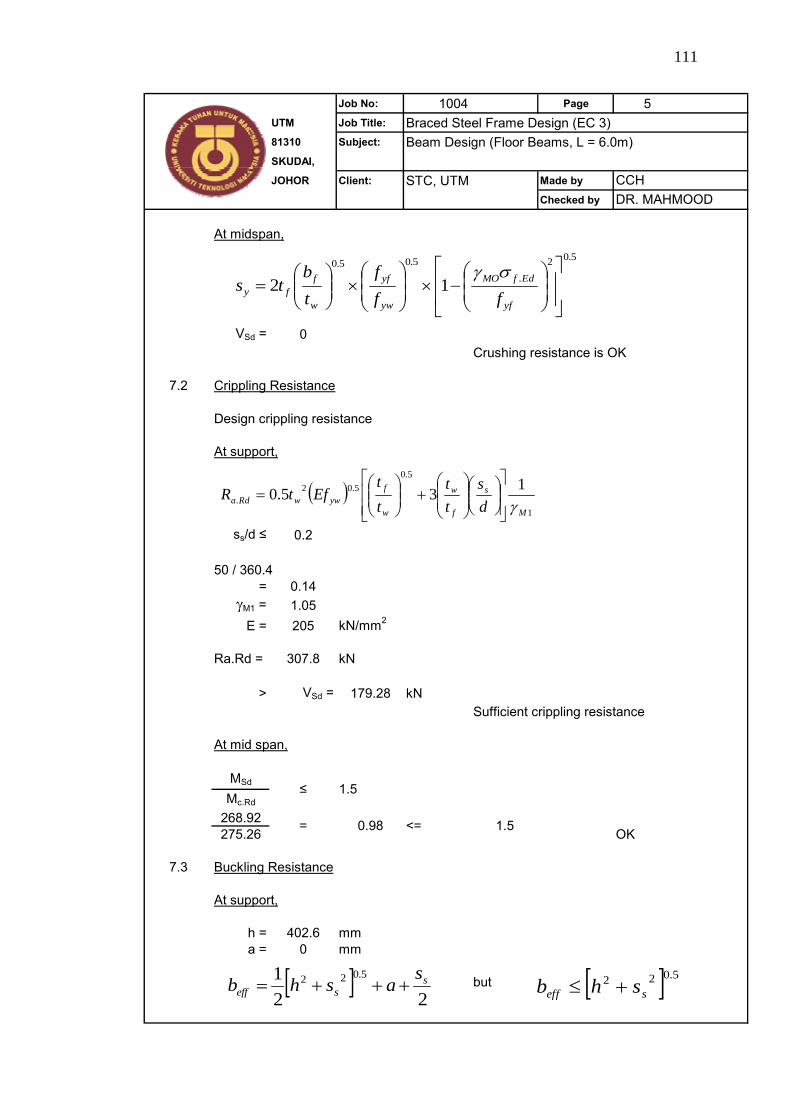
111
Job No: 1004 Page 5UTM Job Title: Braced Steel Frame Design (EC 3)81310 Subject: Beam Design (Floor Beams, L = 6.0m)SKUDAI,
JOHOR Client: STC, UTM Made by
Checked by
At midspan,
VSd = 0Crushing resistance is OK
7.2 Crippling Resistance
Design crippling resistance
At support,
ss/d ≤ 0.2
50 / 360.4= 0.14
γM1 = 1.05E = 205 kN/mm2
Ra.Rd = 307.8 kN
> VSd = 179.28 kNSufficient crippling resistance
At mid span,
MSd
Mc.Rd
268.92275.26 OK
7.3 Buckling Resistance
At support,
h = 402.6 mma = 0 mm
but
≤ 1.5
= 0.98 <= 1.5
CCHDR. MAHMOOD
5.02
.
5.05.0
12⎥⎥
⎦
⎤
⎢⎢
⎣
⎡
⎟⎟⎠
⎞⎜⎜⎝
⎛−×⎟
⎟⎠
⎞⎜⎜⎝
⎛×⎟⎟
⎠
⎞⎜⎜⎝
⎛=
yf
EdfMO
yw
yf
w
ffy ff
ftb
tsσγ
( )1
5.05.02
.135.0M
s
f
w
w
fywwRda d
stt
tt
EftRγ⎥
⎥⎦
⎤
⎢⎢⎣
⎡⎟⎠⎞
⎜⎝⎛⎟⎟⎠
⎞⎜⎜⎝
⎛+⎟⎟
⎠
⎞⎜⎜⎝
⎛=
[ ]22
1 5.022 sseff
sashb +++= [ ] 5.022
seff shb +≤
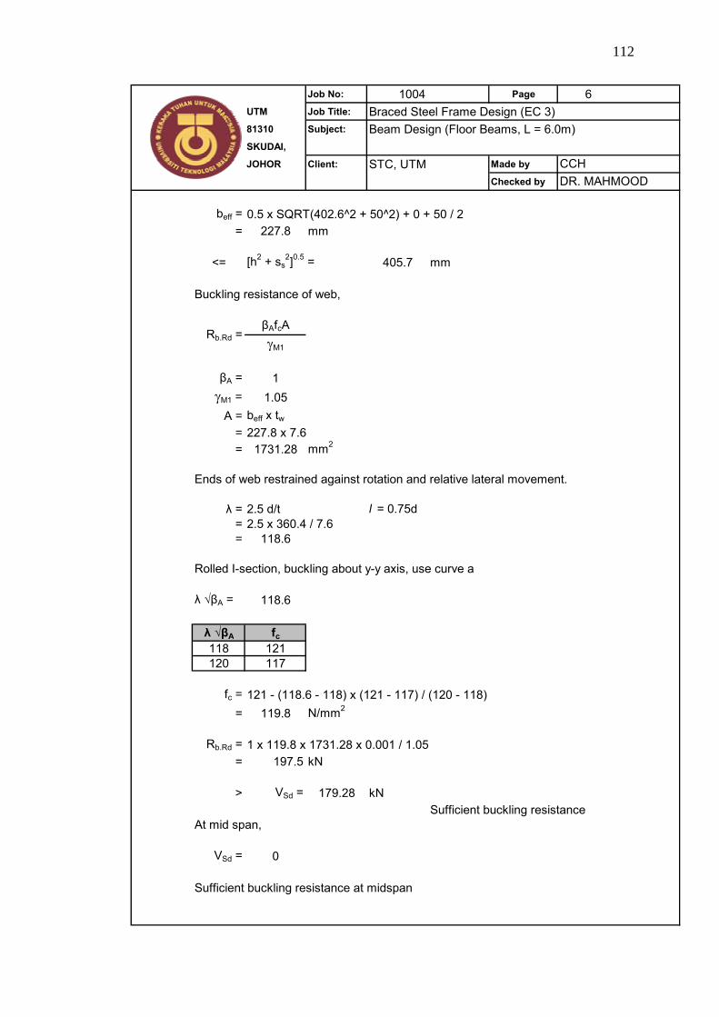
112
Job No: 1004 Page 6UTM Job Title: Braced Steel Frame Design (EC 3)81310 Subject: Beam Design (Floor Beams, L = 6.0m)SKUDAI,
JOHOR Client: STC, UTM Made by
Checked by
beff = 0.5 x SQRT(402.6^2 + 50^2) + 0 + 50 / 2= 227.8 mm
<= [h2 + ss2]0.5 = 405.7 mm
Buckling resistance of web,
βAfcAγM1
βA = 1γM1 = 1.05
A = beff x tw= 227.8 x 7.6= 1731.28 mm2
Ends of web restrained against rotation and relative lateral movement.
λ = 2.5 d/t l = 0.75d= 2.5 x 360.4 / 7.6= 118.6
Rolled I-section, buckling about y-y axis, use curve a
λ √βA = 118.6
λ √βA fc118 121120 117
fc = 121 - (118.6 - 118) x (121 - 117) / (120 - 118)= 119.8 N/mm2
Rb.Rd = 1 x 119.8 x 1731.28 x 0.001 / 1.05= 197.5 kN
> VSd = 179.28 kNSufficient buckling resistance
At mid span,
VSd = 0
Sufficient buckling resistance at midspan
Rb.Rd =
CCHDR. MAHMOOD
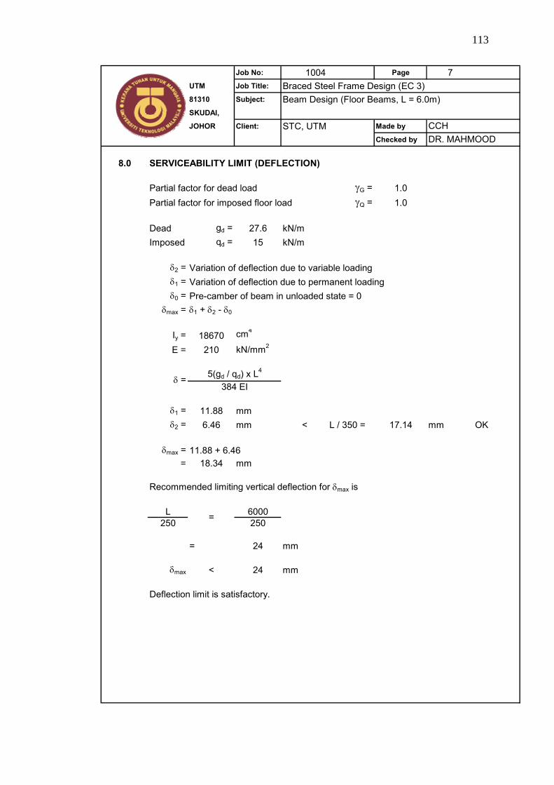
113
Job No: 1004 Page 7UTM Job Title: Braced Steel Frame Design (EC 3)81310 Subject: Beam Design (Floor Beams, L = 6.0m)SKUDAI,
JOHOR Client: STC, UTM Made by
Checked by
8.0 SERVICEABILITY LIMIT (DEFLECTION)
Partial factor for dead load γG = 1.0Partial factor for imposed floor load γQ = 1.0
Dead gd = 27.6 kN/mImposed qd = 15 kN/m
δ2 = Variation of deflection due to variable loadingδ1 = Variation of deflection due to permanent loadingδ0 = Pre-camber of beam in unloaded state = 0
δmax = δ1 + δ2 - δ0
Iy = 18670 cm4
E = 210 kN/mm2
δ1 = 11.88 mmδ2 = 6.46 mm < L / 350 = 17.14 mm OK
δmax = 11.88 + 6.46= 18.34 mm
Recommended limiting vertical deflection for δmax is
L 6000250 250
= 24 mm
δmax < 24 mm
Deflection limit is satisfactory.
δ =
=
CCHDR. MAHMOOD
5(gd / qd) x L4
384 EI

114
APPENDIX C1
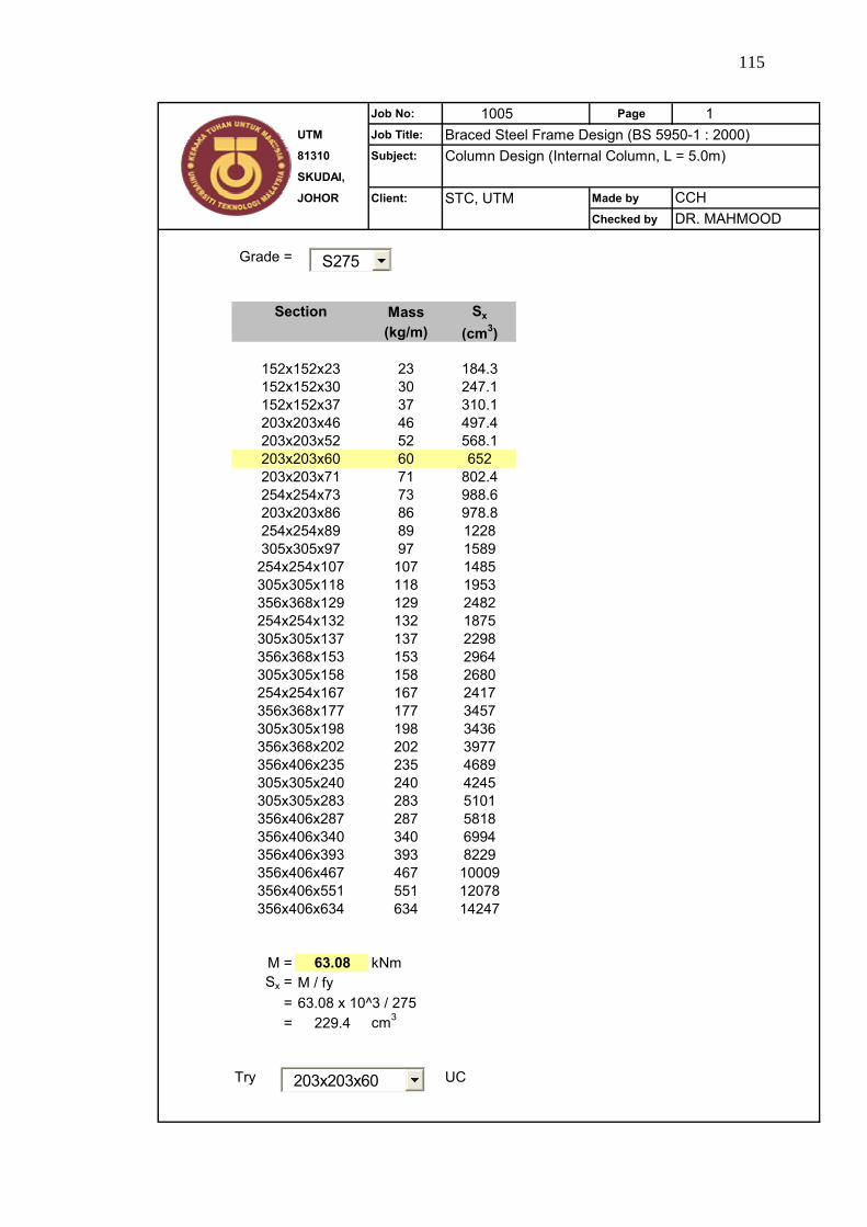
115
Job No: 1005 Page 1UTM Job Title: Braced Steel Frame Design (BS 5950-1 : 2000)81310 Subject: Column Design (Internal Column, L = 5.0m)SKUDAI,
JOHOR Client: STC, UTM Made by
Checked by
Grade =
Mass Sx
(kg/m) (cm3)
23 184.330 247.137 310.146 497.452 568.160 65271 802.473 988.686 978.889 122897 1589107 1485118 1953129 2482132 1875137 2298153 2964158 2680167 2417177 3457198 3436202 3977235 4689240 4245283 5101287 5818340 6994393 8229467 10009551 12078634 14247
M = 63.08 kNmSx = M / fy
= 63.08 x 10^3 / 275= 229.4 cm3
Try UC
356x406x551356x406x634
356x406x287356x406x340356x406x393356x406x467
356x368x202356x406x235305x305x240305x305x283
305x305x158254x254x167356x368x177305x305x198
356x368x129254x254x132305x305x137356x368x153
254x254x89305x305x97254x254x107305x305x118
203x203x60203x203x71254x254x73203x203x86
152x152x30152x152x37203x203x46203x203x52
CCHDR. MAHMOOD
Section
152x152x23
203x203x60
S275
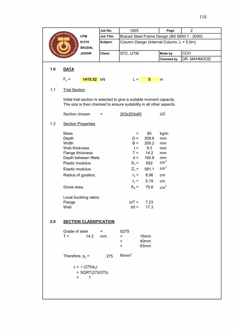
116
Job No: 1005 Page 2UTM Job Title: Braced Steel Frame Design (BS 5950-1 : 2000)81310 Subject: Column Design (Internal Column, L = 5.0m)SKUDAI,
JOHOR Client: STC, UTM Made by
Checked by
1.0 DATA
Fc = 1415.52 kN L = 5 m
1.1
Initial trial section is selected to give a suitable moment capacity.The size is then checked to ensure suitability in all other aspects.
Section chosen = 203x203x60 UC
1.2 Section Properties
Mass = 60 kg/mDepth D = 209.6 mmWidth B = 205.2 mmWeb thickness t = 9.3 mmFlange thickness T = 14.2 mmDepth between fillets d = 160.8 mmPlastic modulus Sx = 652 cm3
Elastic modulus Zx = 581.1 cm3
Radius of gyration, rx = 8.96 cmry = 5.19 cm
Gross area, Ag = 75.8 cm2
Local buckling ratios:Flange b/T = 7.23Web d/t = 17.3
2.0 SECTION CLASSIFICATION
Grade of steel = S275T = 14.2 mm < 16mm
< 40mm< 63mm
Therefore, py = 275 N/mm2
ε = √ (275/py)= SQRT(275/275)= 1
CCHDR. MAHMOOD
Trial Section
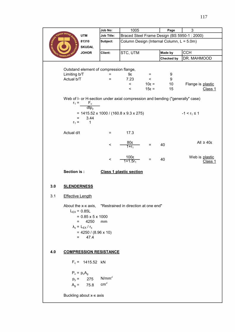
117
Job No: 1005 Page 3UTM Job Title: Braced Steel Frame Design (BS 5950-1 : 2000)81310 Subject: Column Design (Internal Column, L = 5.0m)SKUDAI,
JOHOR Client: STC, UTM Made by
Checked by
Outstand element of compression flange,Limiting b/T = 9ε = 9Actual b/T = 7.23 < 9
< 10ε = 10 Flange is plastic< 15ε = 15 Class 1
Web of I- or H-section under axial compression and bending ("generally" case)r1 = Fc
dtpy
= 1415.52 x 1000 / (160.8 x 9.3 x 275)= 3.44
r1 = 1
Actual d/t = 17.3
80ε All ≥ 40ε1+r1
100ε Web is plastic1+1.5r1 Class 1
Section is : Class 1 plastic section
3.0 SLENDERNESS
3.1 Effective Length
About the x-x axis, "Restrained in direction at one end"LEX = 0.85L
= 0.85 x 5 x 1000= 4250 mm
λx = LEX / rx
= 4250 / (8.96 x 10)= 47.4
4.0 COMPRESSION RESISTANCE
Fc = 1415.52 kN
Pc = pcAg
py = 275 N/mm2
Ag = 75.8 cm2
Buckling about x-x axis
< = 40
CCH
= 40
DR. MAHMOOD
<
-1 < r1 ≤ 1
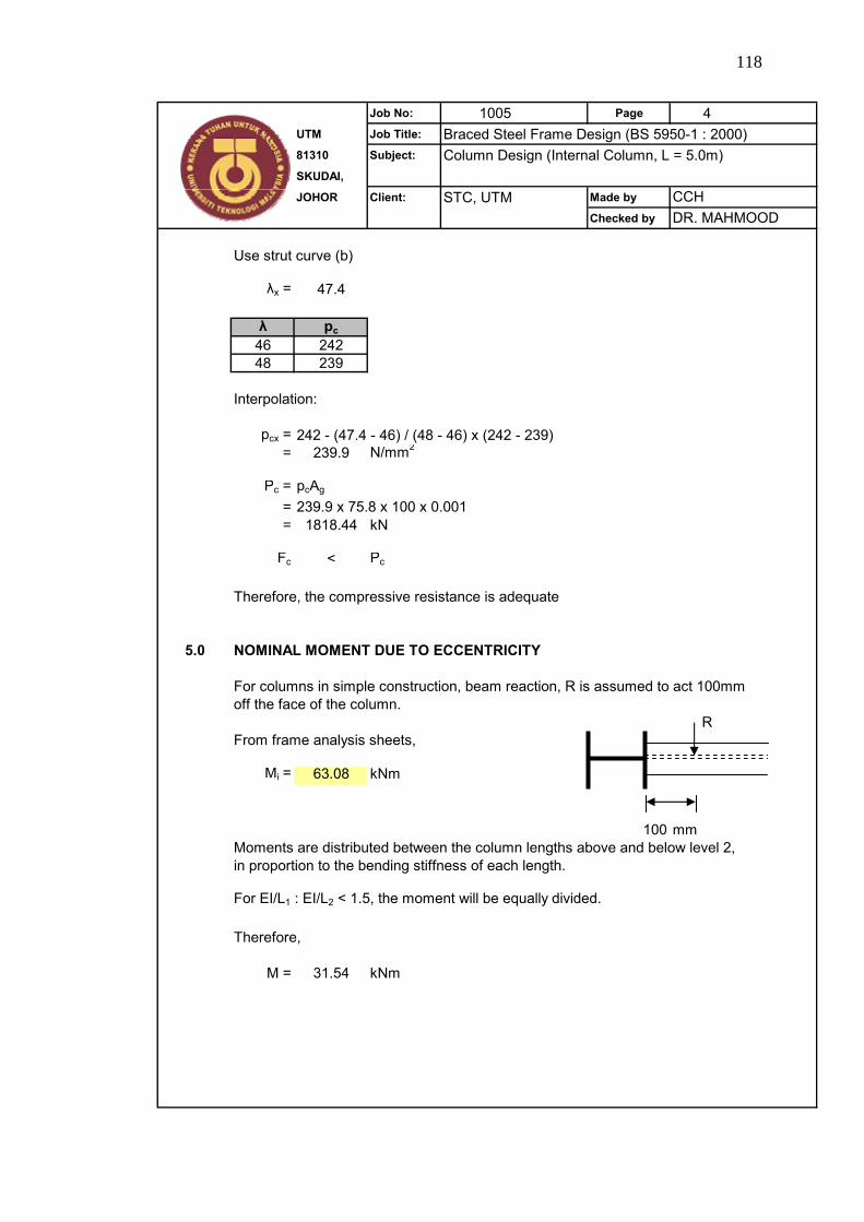
118
Job No: 1005 Page 4UTM Job Title: Braced Steel Frame Design (BS 5950-1 : 2000)81310 Subject: Column Design (Internal Column, L = 5.0m)SKUDAI,
JOHOR Client: STC, UTM Made by
Checked by
Use strut curve (b)
λx = 47.4
λ pc46 24248 239
Interpolation:
pcx = 242 - (47.4 - 46) / (48 - 46) x (242 - 239)= 239.9 N/mm2
Pc = pcAg
= 239.9 x 75.8 x 100 x 0.001= 1818.44 kN
Fc < Pc
Therefore, the compressive resistance is adequate
5.0 NOMINAL MOMENT DUE TO ECCENTRICITY
For columns in simple construction, beam reaction, R is assumed to act 100mmoff the face of the column.
RFrom frame analysis sheets,
Mi = 63.08 kNm
100 mmMoments are distributed between the column lengths above and below level 2,in proportion to the bending stiffness of each length.
For EI/L1 : EI/L2 < 1.5, the moment will be equally divided.
Therefore,
M = 31.54 kNm
CCHDR. MAHMOOD
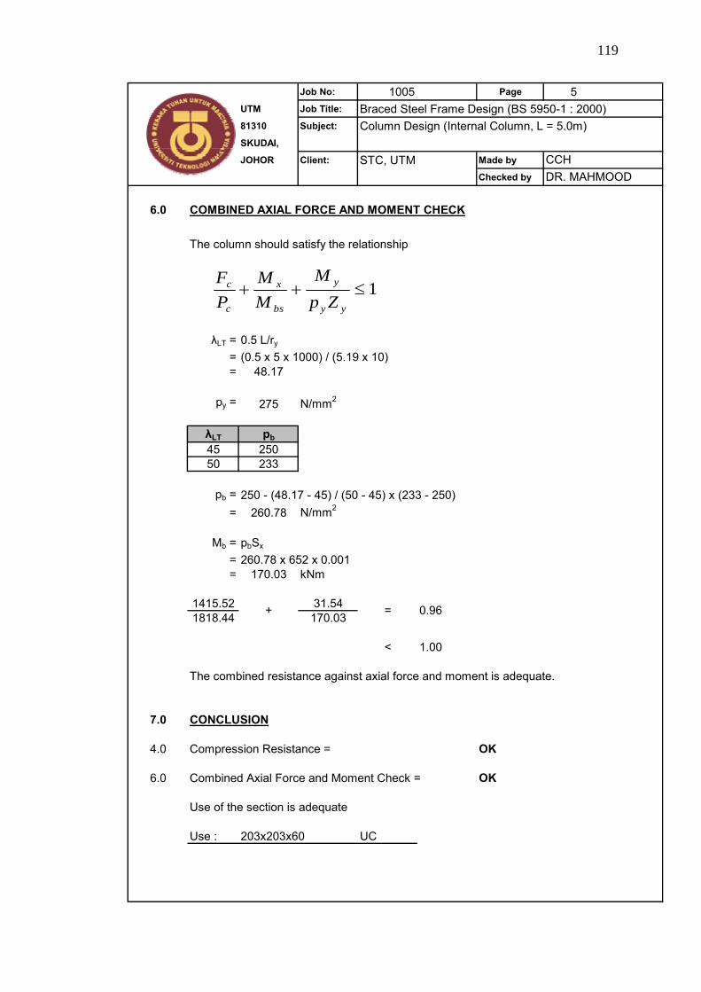
119
Job No: 1005 Page 5UTM Job Title: Braced Steel Frame Design (BS 5950-1 : 2000)81310 Subject: Column Design (Internal Column, L = 5.0m)SKUDAI,
JOHOR Client: STC, UTM Made by
Checked by
6.0 COMBINED AXIAL FORCE AND MOMENT CHECK
The column should satisfy the relationship
λLT = 0.5 L/ry
= (0.5 x 5 x 1000) / (5.19 x 10)= 48.17
py = 275 N/mm2
λLT pb45 25050 233
pb = 250 - (48.17 - 45) / (50 - 45) x (233 - 250)= 260.78 N/mm2
Mb = pbSx
= 260.78 x 652 x 0.001= 170.03 kNm
1415.52 31.541818.44 170.03
< 1.00
The combined resistance against axial force and moment is adequate.
7.0 CONCLUSION
4.0 Compression Resistance = OK
6.0 Combined Axial Force and Moment Check = OK
Use of the section is adequate
Use : 203x203x60 UC
+ = 0.96
CCHDR. MAHMOOD
1≤++yy
y
bs
x
c
c
ZpM
MM
PF
120
APPENDIX C2
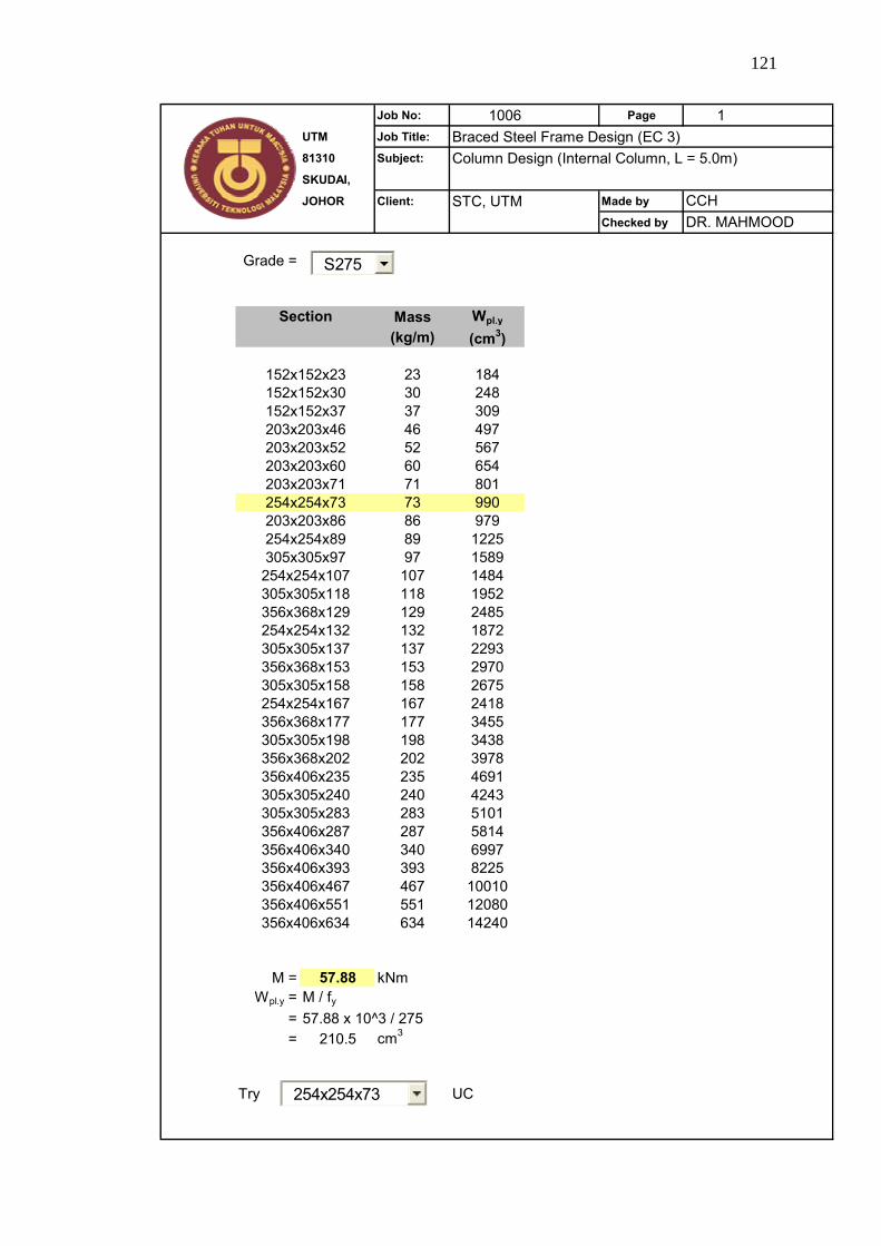
121
Job No: 1006 Page 1UTM Job Title: Braced Steel Frame Design (EC 3)81310 Subject: Column Design (Internal Column, L = 5.0m)SKUDAI,
JOHOR Client: STC, UTM Made by
Checked by
Grade =
Mass Wpl.y
(kg/m) (cm3)
23 18430 24837 30946 49752 56760 65471 80173 99086 97989 122597 1589107 1484118 1952129 2485132 1872137 2293153 2970158 2675167 2418177 3455198 3438202 3978235 4691240 4243283 5101287 5814340 6997393 8225467 10010551 12080634 14240
M = 57.88 kNmWpl.y = M / fy
= 57.88 x 10^3 / 275= 210.5 cm3
Try UC
356x406x467356x406x551356x406x634
305x305x283356x406x287356x406x340356x406x393
305x305x198356x368x202356x406x235305x305x240
356x368x153305x305x158254x254x167356x368x177
305x305x118356x368x129254x254x132305x305x137
203x203x86254x254x89305x305x97254x254x107
152x152x23152x152x30152x152x37203x203x46
CCHDR. MAHMOOD
Section
203x203x52203x203x60203x203x71254x254x73
254x254x73
S275
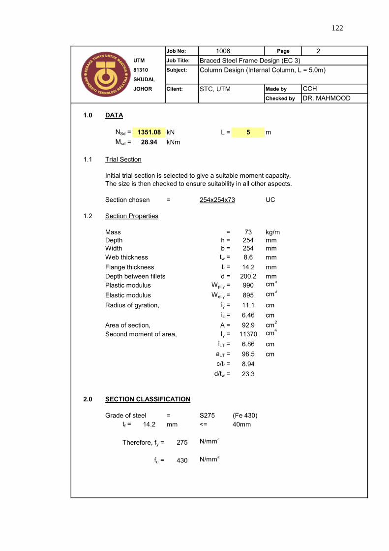
122
Job No: 1006 Page 2UTM Job Title: Braced Steel Frame Design (EC 3)81310 Subject: Column Design (Internal Column, L = 5.0m)SKUDAI,
JOHOR Client: STC, UTM Made by
Checked by
1.0 DATA
NSd = 1351.08 kN L = 5 mMsd = 28.94 kNm
1.1
Initial trial section is selected to give a suitable moment capacity.The size is then checked to ensure suitability in all other aspects.
Section chosen = 254x254x73 UC
1.2 Section Properties
Mass = 73 kg/mDepth h = 254 mmWidth b = 254 mmWeb thickness tw = 8.6 mmFlange thickness tf = 14.2 mmDepth between fillets d = 200.2 mmPlastic modulus Wpl.y = 990 cm3
Elastic modulus Wel.y = 895 cm3
Radius of gyration, iy = 11.1 cmiz = 6.46 cm
Area of section, A = 92.9 cm2
Second moment of area, Iy = 11370 cm4
iLT = 6.86 cmaLT = 98.5 cmc/tf = 8.94
d/tw = 23.3
2.0 SECTION CLASSIFICATION
Grade of steel = S275 (Fe 430)tf = 14.2 mm <= 40mm
275 N/mm2
fu = 430 N/mm2
Therefore, fy =
CCHDR. MAHMOOD
Trial Section
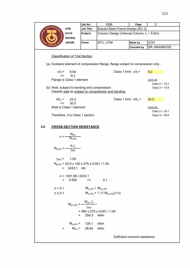
123
Job No: 1006 Page 3UTM Job Title: Braced Steel Frame Design (EC 3)81310 Subject: Column Design (Internal Column, L = 5.0m)SKUDAI,
JOHOR Client: STC, UTM Made by
Checked by
Classification of Trial Section
(a) Outstand element of compression flange, flange subject to compression only :
c/tf = 8.94 Class 1 limit : c/tf = 9.2<= 9.2
Flange is Class 1 element Limit c/tfClass 2 = 10.2
(b) Web, subject to bending and compression : Class 3 = 13.9Classify web as subject to compression and bending
d/tw = 23.3 Class 1 limit : d/tw = 30.5<= 30.5
Web is Class 1 element Limit d/twClass 2 = 35.1
Therefore, it is Class 1 section Class 3 = 38.8
3.0 CROSS-SECTION RESISTANCE
NSdNpl.Rd
A fyγMO
γMO = 1.05Npl.Rd = 92.9 x 100 x 275 x 0.001 / 1.05
= 2433.1 kN
n = 1351.08 / 2433.1= 0.555 >= 0.1
n < 0.1 Mny.Rd = Mpl.y.Rd
n ≥ 0.1 Mny.Rd = 1.11 Mpl.y.Rd(1-n)
Wpl.y fyγMO
= 990 x 275 x 0.001 / 1.05= 259.3 kNm
Mny.Rd = 128.1 kNm> MSd = 28.94 kNm
Sufficient moment resistance
n =
Npl.Rd =
CCHDR. MAHMOOD
Mpl.y.Rd =
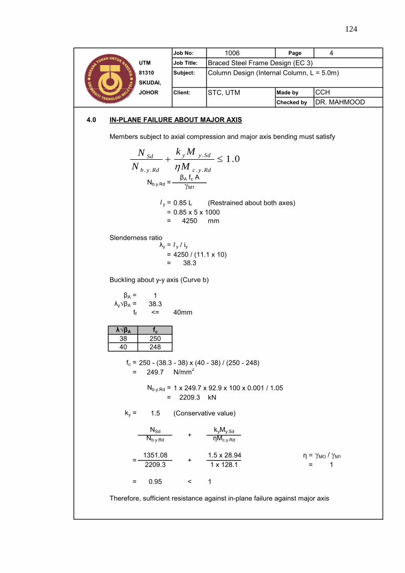
124
Job No: 1006 Page 4UTM Job Title: Braced Steel Frame Design (EC 3)81310 Subject: Column Design (Internal Column, L = 5.0m)SKUDAI,
JOHOR Client: STC, UTM Made by
Checked by
4.0 IN-PLANE FAILURE ABOUT MAJOR AXIS
Members subject to axial compression and major axis bending must satisfy
βA fc AγM1
l y = 0.85 L (Restrained about both axes)= 0.85 x 5 x 1000= 4250 mm
Slenderness ratioλy = l y / iy
= 4250 / (11.1 x 10)= 38.3
Buckling about y-y axis (Curve b)
βA = 1λy√βA = 38.3
tf <= 40mm
λ√βA fc38 25040 248
fc = 250 - (38.3 - 38) x (40 - 38) / (250 - 248)= 249.7 N/mm2
Nb.y.Rd = 1 x 249.7 x 92.9 x 100 x 0.001 / 1.05= 2209.3 kN
ky = 1.5 (Conservative value)
NSd kyMy.SdNb.y.Rd ηMc.y.Rd
1351.08 1.5 x 28.94 η = γMO / γM1
2209.3 1 x 128.1 = 1
= 0.95 < 1
Therefore, sufficient resistance against in-plane failure against major axis
CCH
Nb.y.Rd =
DR. MAHMOOD
+
= +
0.1..
.
..
≤+Rdyc
Sdyy
Rdyb
Sd
MMk
NN
η
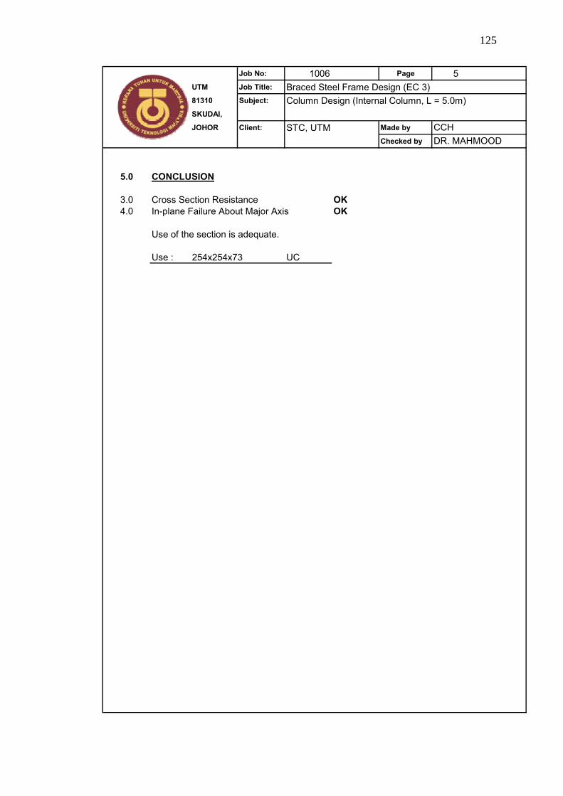
125
Job No: 1006 Page 5UTM Job Title: Braced Steel Frame Design (EC 3)81310 Subject: Column Design (Internal Column, L = 5.0m)SKUDAI,
JOHOR Client: STC, UTM Made by
Checked by
5.0 CONCLUSION
3.0 Cross Section Resistance OK4.0 In-plane Failure About Major Axis OK
Use of the section is adequate.
Use : 254x254x73 UC
CCHDR. MAHMOOD
126
APPENDIX D

127
Job No: 1004 Page 1 Rev 1UTM Job Title: Braced Steel Frame Design (EC 3)81310 Subject: Beam Design (Floor Beams, L = 6.0m)SKUDAI,
JOHOR Client: STC, UTM Made by
Checked by
Grade =
Mass Wpl.y Mass Wpl.y
(kg/m) (cm3) (kg/m) (cm3)
19 171 57 100922 260 60 119523 232 60 128325 259 67 121325 307 67 134625 336 67 144228 354 67 147228 408 74 150930 313 74 162431 395 74 165933 481 82 180233 539 82 183237 485 82 205837 540 89 202039 654 92 236639 718 98 223440 626 101 261942 612 101 288743 568 109 282745 773 113 328746 722 122 320346 889 125 367348 706 140 413951 895 149 457552 1096 179 551554 843 238 746254 1051
M = 268.92 kNmWpl.y = M / fy
= 268.92 x 10^3 / 275= 977.9 cm3
Try UB
203x102x23254x102x22178x102x19
254x102x28305x102x25254x102x25203x133x25
305x102x33254x146x31203x133x30305x102x28
356x127x39305x127x37254x146x37356x127x33
254x146x43305x127x42305x165x40406x140x39
305x127x48406x140x46305x165x46356x171x45
406x178x54305x165x54457x152x52356x171x51
610x229x140610x305x149610x305x179610x305x238
533x210x109610x229x113533x210x122610x229x125
533x210x92457x191x98533x210x101610x229x101
457x152x82457x191x82533x210x82457x191x89
457x191x67406x178x74457x152x74457x191x74
457x152x60356x171x67406x178x67457x152x67
Section Section
356x171x57406x178x60
CCHDR. MAHMOOD
457x152x52
S275

128
Job No: 1004 Page 2 Rev 1UTM Job Title: Braced Steel Frame Design (EC 3)81310 Subject: Beam Design (Floor Beams, L = 6.0m)SKUDAI,
JOHOR Client: STC, UTM Made by
Checked by
1.0 DATA
1.1 L = 6 m
Initial trial section is selected to give a suitable moment capacity.The size is then checked to ensure suitability in all other aspects.
Section chosen = 457x152x52 UB
1.2 Section Properties
Mass = 52 kg/mDepth h = 449.8 mmWidth b = 152.4 mmWeb thickness tw = 7.6 mmFlange thickness tf = 10.9 mmDepth between fillets d = 407.6 mmPlastic modulus Wpl.y = 1096 cm3
Elastic modulus Wel.y = 950 cm3
Shear area, Av = 36.5 cm2
Area of section, A = 66.6 cm2
Second moment of area, Iy = 21370 cm4
iLT = 3.59 cmaLT = 121 cmc/tf = 6.99
d/tw = 53.6
2.0 SECTION CLASSIFICATION
Grade of steel = S275 (Fe 430)t = 10.9 mm <= 40mm
275 N/mm2
fu = 430 N/mm2
Trial Section
Therefore, fy =
CCHDR. MAHMOOD
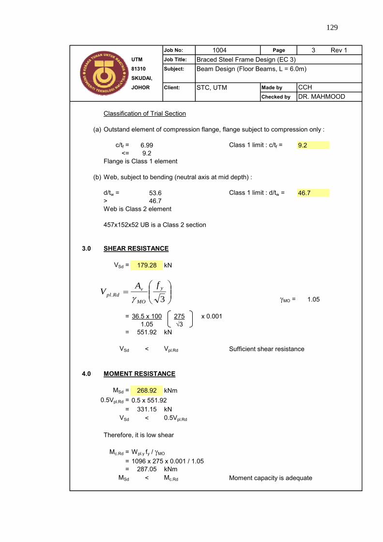
129
Job No: 1004 Page 3 Rev 1UTM Job Title: Braced Steel Frame Design (EC 3)81310 Subject: Beam Design (Floor Beams, L = 6.0m)SKUDAI,
JOHOR Client: STC, UTM Made by
Checked by
Classification of Trial Section
(a) Outstand element of compression flange, flange subject to compression only :
c/tf = 6.99 Class 1 limit : c/tf = 9.2<= 9.2
Flange is Class 1 element
(b) Web, subject to bending (neutral axis at mid depth) :
d/tw = 53.6 Class 1 limit : d/tw = 46.7> 46.7Web is Class 2 element
457x152x52 UB is a Class 2 section
3.0 SHEAR RESISTANCE
VSd = 179.28 kN
γMO = 1.05
= 36.5 x 100 275 x 0.0011.05 √3
= 551.92 kN
VSd < Vpl.Rd Sufficient shear resistance
4.0 MOMENT RESISTANCE
MSd = 268.92 kNm0.5Vpl.Rd = 0.5 x 551.92
= 331.15 kNVSd < 0.5Vpl.Rd
Therefore, it is low shear
Mc.Rd = Wpl.y fy / γMO
= 1096 x 275 x 0.001 / 1.05= 287.05 kNm
MSd < Mc.Rd Moment capacity is adequate
DR. MAHMOODCCH
⎟⎟⎠
⎞⎜⎜⎝
⎛=
3.y
MO
vRdpl
fAV
γ
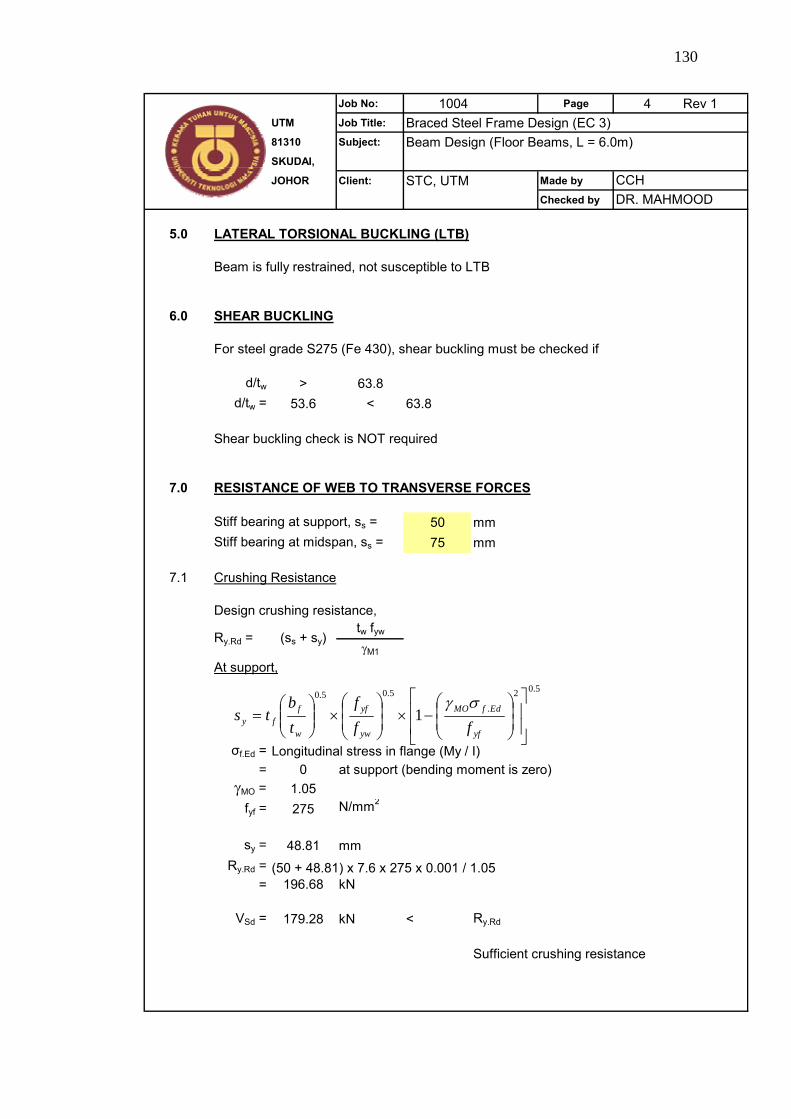
130
Job No: 1004 Page 4 Rev 1UTM Job Title: Braced Steel Frame Design (EC 3)81310 Subject: Beam Design (Floor Beams, L = 6.0m)SKUDAI,
JOHOR Client: STC, UTM Made by
Checked by
5.0 LATERAL TORSIONAL BUCKLING (LTB)
Beam is fully restrained, not susceptible to LTB
6.0 SHEAR BUCKLING
For steel grade S275 (Fe 430), shear buckling must be checked if
d/tw > 63.8d/tw = 53.6 < 63.8
Shear buckling check is NOT required
7.0 RESISTANCE OF WEB TO TRANSVERSE FORCES
Stiff bearing at support, ss = 50 mmStiff bearing at midspan, ss = 75 mm
7.1 Crushing Resistance
Design crushing resistance,tw fyw
γM1
At support,
σf.Ed = Longitudinal stress in flange (My / I)= 0 at support (bending moment is zero)
γMO = 1.05fyf = 275 N/mm2
sy = 48.81 mmRy.Rd = (50 + 48.81) x 7.6 x 275 x 0.001 / 1.05
= 196.68 kN
VSd = 179.28 kN < Ry.Rd
Sufficient crushing resistance
Ry.Rd = (ss + sy)
CCHDR. MAHMOOD
5.02
.
5.05.0
1⎥⎥
⎦
⎤
⎢⎢
⎣
⎡
⎟⎟⎠
⎞⎜⎜⎝
⎛−×⎟
⎟⎠
⎞⎜⎜⎝
⎛×⎟⎟
⎠
⎞⎜⎜⎝
⎛=
yf
EdfMO
yw
yf
w
ffy ff
ftb
tsσγ

131
Job No: 1004 Page 5 Rev 1UTM Job Title: Braced Steel Frame Design (EC 3)81310 Subject: Beam Design (Floor Beams, L = 6.0m)SKUDAI,
JOHOR Client: STC, UTM Made by
Checked by
At midspan,
VSd = 0Crushing resistance is OK
7.2 Crippling Resistance
Design crippling resistance
At support,
ss/d ≤ 0.2
50 / 407.6= 0.12
γM1 = 1.05E = 205 kN/mm2
Ra.Rd = 299.16 kN
> VSd = 179.28 kNSufficient crippling resistance
At mid span,
MSd
Mc.Rd
268.92287.05 OK
7.3 Buckling Resistance
At support,
h = 449.8 mma = 0 mm
but
≤ 1.5
= 0.94 <= 1.5
CCHDR. MAHMOOD
5.02
.
5.05.0
12⎥⎥
⎦
⎤
⎢⎢
⎣
⎡
⎟⎟⎠
⎞⎜⎜⎝
⎛−×⎟
⎟⎠
⎞⎜⎜⎝
⎛×⎟⎟
⎠
⎞⎜⎜⎝
⎛=
yf
EdfMO
yw
yf
w
ffy ff
ftb
tsσγ
( )1
5.05.02
.135.0M
s
f
w
w
fywwRda d
stt
tt
EftRγ⎥
⎥⎦
⎤
⎢⎢⎣
⎡⎟⎠⎞
⎜⎝⎛⎟⎟⎠
⎞⎜⎜⎝
⎛+⎟⎟
⎠
⎞⎜⎜⎝
⎛=
[ ]22
1 5.022 sseff
sashb +++= [ ] 5.022
seff shb +≤
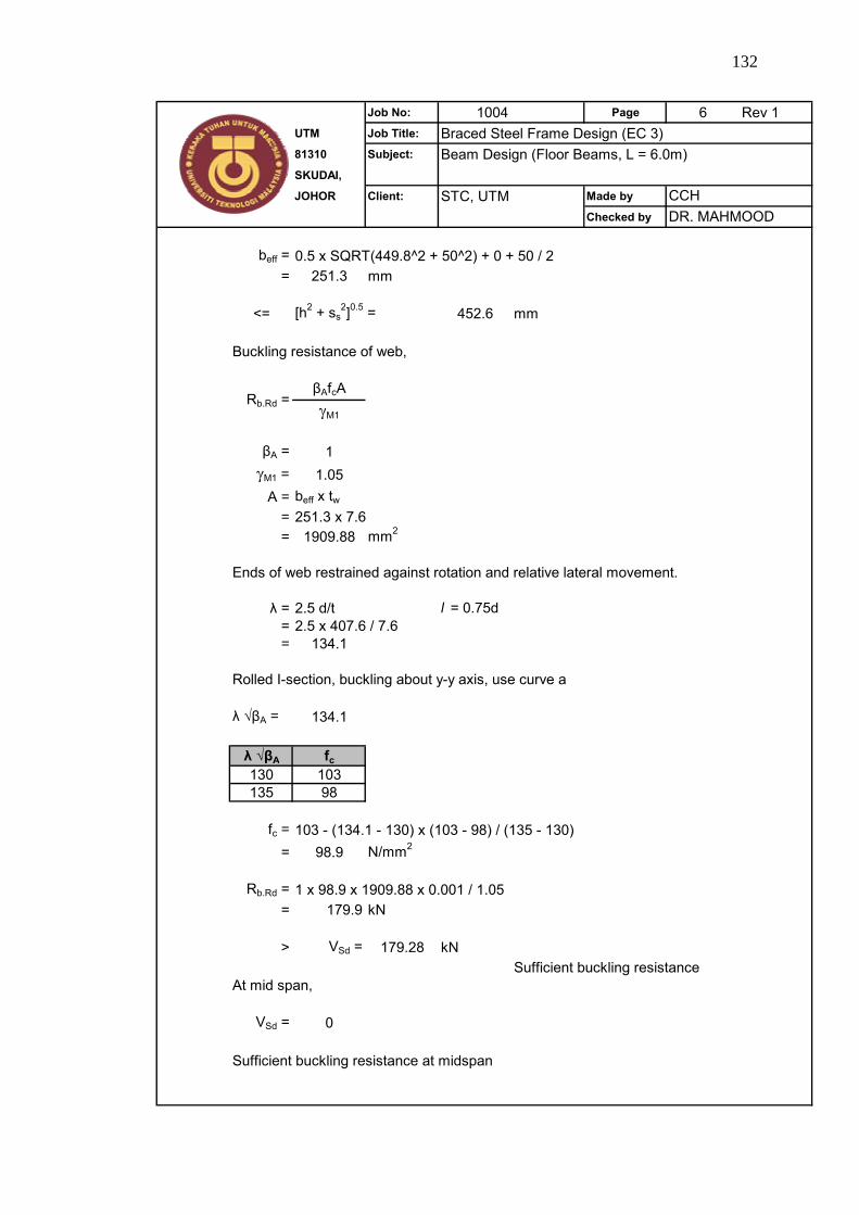
132
Job No: 1004 Page 6 Rev 1UTM Job Title: Braced Steel Frame Design (EC 3)81310 Subject: Beam Design (Floor Beams, L = 6.0m)SKUDAI,
JOHOR Client: STC, UTM Made by
Checked by
beff = 0.5 x SQRT(449.8^2 + 50^2) + 0 + 50 / 2= 251.3 mm
<= [h2 + ss2]0.5 = 452.6 mm
Buckling resistance of web,
βAfcAγM1
βA = 1γM1 = 1.05
A = beff x tw= 251.3 x 7.6= 1909.88 mm2
Ends of web restrained against rotation and relative lateral movement.
λ = 2.5 d/t l = 0.75d= 2.5 x 407.6 / 7.6= 134.1
Rolled I-section, buckling about y-y axis, use curve a
λ √βA = 134.1
λ √βA fc130 103135 98
fc = 103 - (134.1 - 130) x (103 - 98) / (135 - 130)= 98.9 N/mm2
Rb.Rd = 1 x 98.9 x 1909.88 x 0.001 / 1.05= 179.9 kN
> VSd = 179.28 kNSufficient buckling resistance
At mid span,
VSd = 0
Sufficient buckling resistance at midspan
Rb.Rd =
CCHDR. MAHMOOD

133
Job No: 1004 Page 7 Rev 1UTM Job Title: Braced Steel Frame Design (EC 3)81310 Subject: Beam Design (Floor Beams, L = 6.0m)SKUDAI,
JOHOR Client: STC, UTM Made by
Checked by
8.0 SERVICEABILITY LIMIT (DEFLECTION)
Partial factor for dead load γG = 1.0Partial factor for imposed floor load γQ = 1.0
Dead gd = 27.6 kN/mImposed qd = 15 kN/m
δ2 = Variation of deflection due to variable loadingδ1 = Variation of deflection due to permanent loadingδ0 = Pre-camber of beam in unloaded state = 0
δmax = δ1 + δ2 - δ0
Iy = 21370 cm4
E = 210 kN/mm2
δ1 = 7.26 mmδ2 = 3.95 mm < L / 350 = 17.14 mm OK
δmax = 7.26 + 3.95= 11.21 mm
Recommended limiting vertical deflection for δmax is
L 6000250 250
= 24 mm
δmax < 24 mm
Deflection limit is satisfactory.
δ =
=
CCHDR. MAHMOOD
3.5(gd / qd) x L4
384 EI