
COE758 Xilinx ISE 9.2 Tutorial 2 - Ryerson Universitylkirisch/ele758/handouts/Tutorial2_Chip... ·...
35
COE758 ‐ Xilinx ISE 9.2 Tutorial 2 ChipScope Overview ChipScope Overview Integrating ChipScope Pro into a project
Transcript of COE758 Xilinx ISE 9.2 Tutorial 2 - Ryerson Universitylkirisch/ele758/handouts/Tutorial2_Chip... ·...
COE758 ‐ Xilinx ISE 9.2 Tutorial 2ChipScope OverviewChipScope Overview
Integrating ChipScope Pro into a project
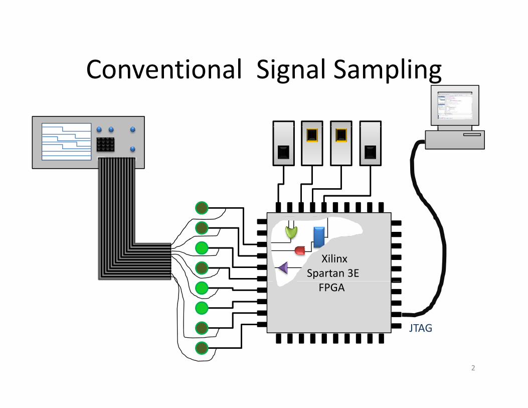
Conventional Signal SamplingConventional Signal Sampling
XilinxSpartan 3EFPGA
JTAG
2

ChipScope Pro Signal SamplingChipScope Pro Signal Sampling
XilinxSpartan 3EFPGA
JTAG
ChipScope Pro
3
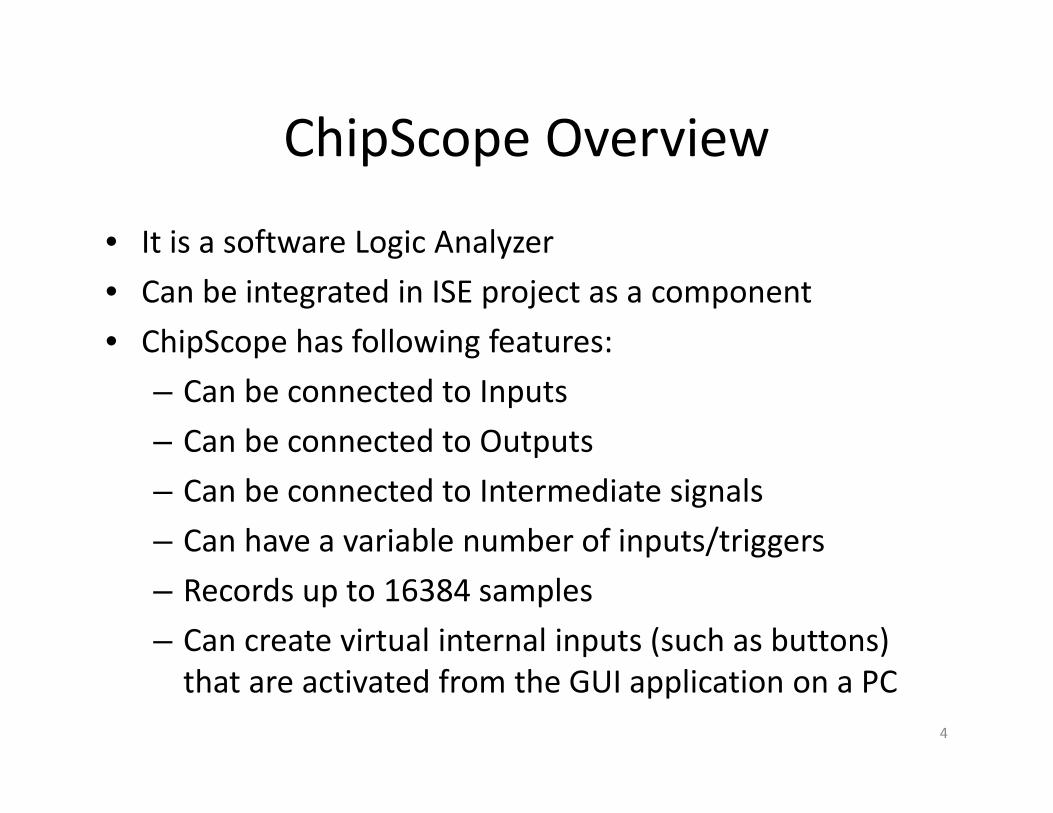
ChipScope OverviewChipScope Overview
• It is a software Logic Analyzers a so a e og c a y e
• Can be integrated in ISE project as a component
• ChipScope has following features:p p g
– Can be connected to Inputs
– Can be connected to Outputs
– Can be connected to Intermediate signals
– Can have a variable number of inputs/triggers
– Records up to 16384 samples
– Can create virtual internal inputs (such as buttons) that are activated from the GUI application on a PC
4
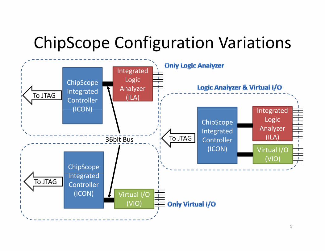
ChipScope Configuration VariationsChipScope Configuration VariationsIntegrated
L iChipScope Integrated Controller(ICON)
Logic Analyzer(ILA)
Integrated
To JTAG
(ICON)
ChipScope Integrated Controller
IntegratedLogic
Analyzer(ILA)To JTAG36bit Bus
ChipScope d
Controller(ICON) Virtual I/O
(VIO)
36bit Bus
Integrated Controller(ICON) Virtual I/O
(VIO)
To JTAG
(VIO)
5

Integration ChipScope ICON and ILA f linto Project from Tutorial 1
• Before inserting components we need to:e o e se g co po e s e eed o
– Generate ICON for the project
– Generate ILA with appropriate amount of inputs, pp p p ,and triggers
Open ChipScope Pro Core Generator
6
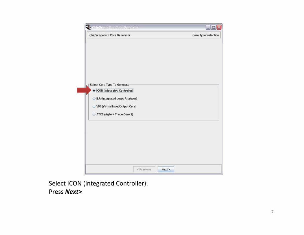
Select ICON (integrated Controller).Press Next>Press Next>
7

1
2
3
1. Specify directory where the project is located2 Select appropriate FPGA device (Spartan3E)2. Select appropriate FPGA device (Spartan3E)3. Select number of Control Ports. In this case it is 1 since we only have ILAPress Next>
8
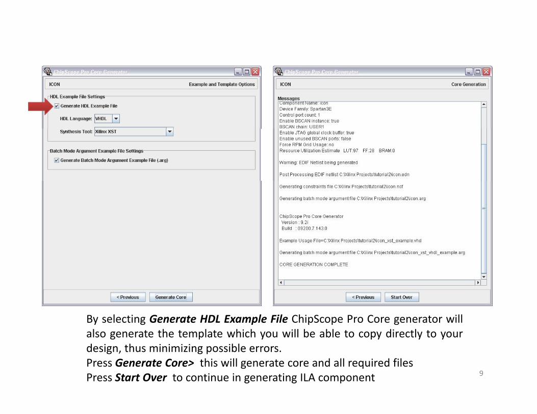
By selecting Generate HDL Example File ChipScope Pro Core generator willalso generate the template which you will be able to copy directly to yourg p y py y ydesign, thus minimizing possible errors.Press Generate Core> this will generate core and all required filesPress Start Over to continue in generating ILA component 9

This time select ILA (Integrated Logic Analyzer) and Press Next>As before, make sure that Output Netlist: is placed in the project directoryp p p j yand Spartan3E is selected as Device Family. By default these settingsshould be already present.Press Next> 10
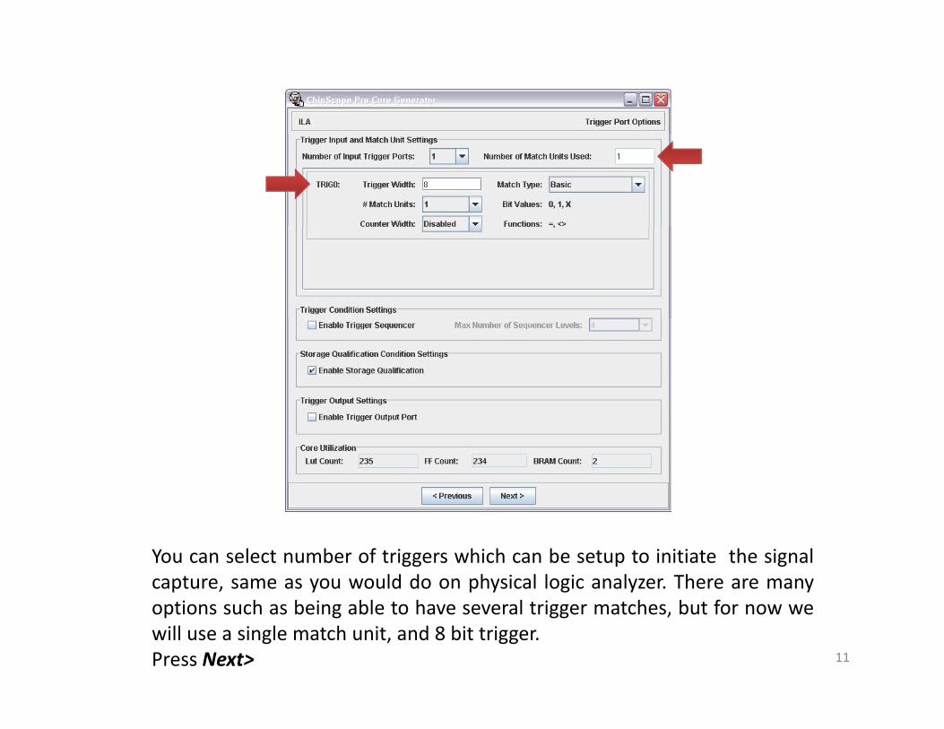
You can select number of triggers which can be setup to initiate the signalcapture, same as you would do on physical logic analyzer. There are manyoptions such as being able to have several trigger matches, but for now wewill use a single match unit, and 8 bit trigger.Press Next> 11
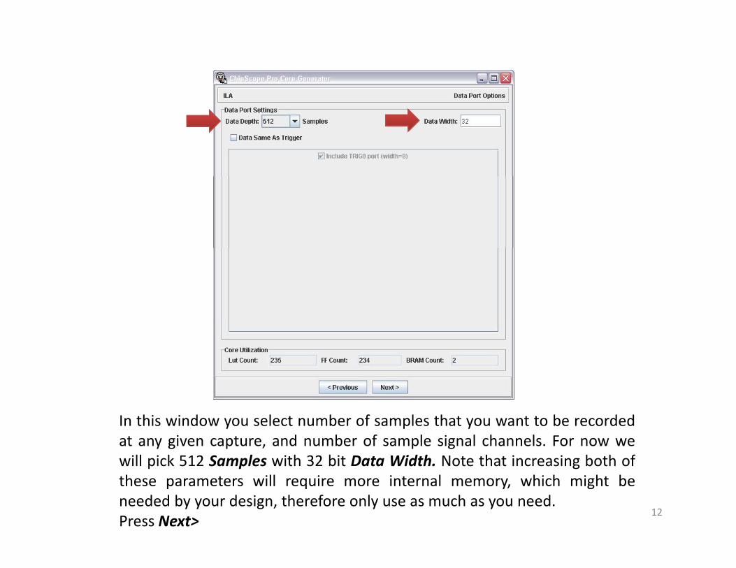
In this window you select number of samples that you want to be recordedat any given capture, and number of sample signal channels. For now wewill pick 512 Samples with 32 bit Data Width Note that increasing both ofwill pick 512 Samples with 32 bit Data Width. Note that increasing both ofthese parameters will require more internal memory, which might beneeded by your design, therefore only use as much as you need.Press Next>
12
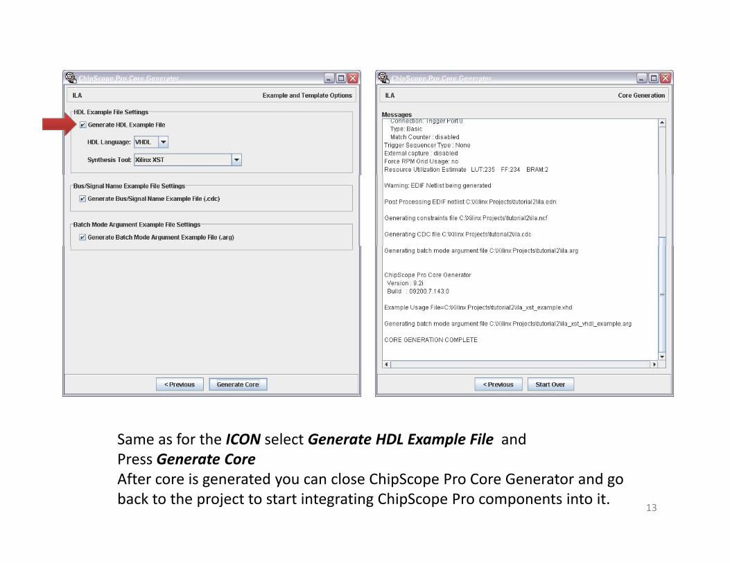
Same as for the ICON select Generate HDL Example File and Press Generate CorePress Generate CoreAfter core is generated you can close ChipScope Pro Core Generator and go back to the project to start integrating ChipScope Pro components into it.
13
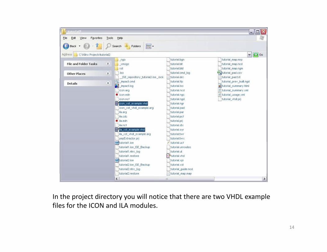
In the project directory you will notice that there are two VHDL example files for the ICON and ILA modulesfiles for the ICON and ILA modules.
14

You will need to open the example files either in a text editor, or directly in the Xilinx ISEthe Xilinx ISE.
15

Declaration
Instantiation
In these files you will find component declaration, and instantiation asshown in the window above These sections can be directly copied to theshown in the window above. These sections can be directly copied to theproject which in turn will initialize these components in your project.
16
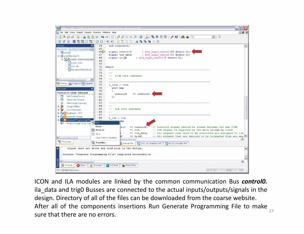
ICON and ILA modules are linked by the common communication Bus control0.ila data and trig0 Busses are connected to the actual inputs/outputs/signals in theila_data and trig0 Busses are connected to the actual inputs/outputs/signals in thedesign. Directory of all of the files can be downloaded from the coarse website.After all of the components insertions Run Generate Programming File to makesure that there are no errors.
17
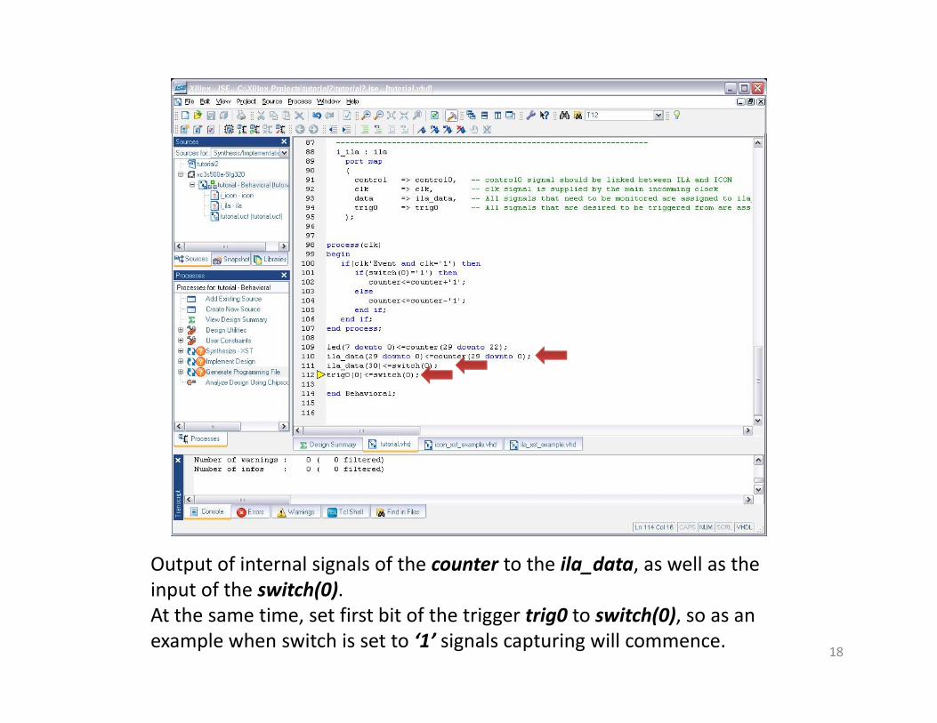
Output of internal signals of the counter to the ila_data, as well as the input of the switch(0)input of the switch(0).At the same time, set first bit of the trigger trig0 to switch(0), so as an example when switch is set to ‘1’ signals capturing will commence.
18
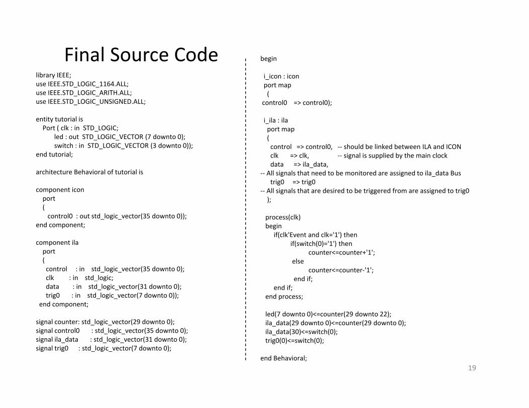
library IEEE;
begin
i icon : icon
Final Source Codelibrary IEEE;use IEEE.STD_LOGIC_1164.ALL;use IEEE.STD_LOGIC_ARITH.ALL;use IEEE.STD_LOGIC_UNSIGNED.ALL;
entity tutorial isPort ( clk in STD LOGIC
i_icon : iconport map(
control0 => control0);
i_ila : ilaPort ( clk : in STD_LOGIC;
led : out STD_LOGIC_VECTOR (7 downto 0);switch : in STD_LOGIC_VECTOR (3 downto 0));
end tutorial;
architecture Behavioral of tutorial is
port map(control => control0, ‐‐ should be linked between ILA and ICONclk => clk, ‐‐ signal is supplied by the main clockdata => ila_data,
‐‐ All signals that need to be monitored are assigned to ila_data Bus
component iconport(control0 : out std_logic_vector(35 downto 0));
end component;
trig0 => trig0‐‐ All signals that are desired to be triggered from are assigned to trig0);
process(clk)begin
component ilaport(control : in std_logic_vector(35 downto 0);clk : in std_logic;
if(clk'Event and clk='1') thenif(switch(0)='1') then
counter<=counter+'1';else
counter<=counter‐'1';end if;
data : in std_logic_vector(31 downto 0);trig0 : in std_logic_vector(7 downto 0));
end component;
signal counter: std_logic_vector(29 downto 0);signal control0 : std logic vector(35 downto 0);
;end if;
end process;
led(7 downto 0)<=counter(29 downto 22);ila_data(29 downto 0)<=counter(29 downto 0);ila data(30)<=switch(0);
19
signal control0 : std_logic_vector(35 downto 0);signal ila_data : std_logic_vector(31 downto 0);signal trig0 : std_logic_vector(7 downto 0);
ila_data(30)<=switch(0);trig0(0)<=switch(0);
end Behavioral;

After all of the ILA signals were assigned Run the Generate ProgrammingFile and correct all of the errors that are encounteredFile and correct all of the errors that are encountered.At this point platform can be configured with the configuration file andChipScope Pro can be used to sample the signals.
20
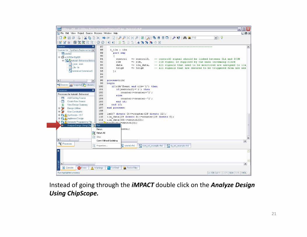
Instead of going through the iMPACT double click on the Analyze Design Using ChipScopeUsing ChipScope.
21
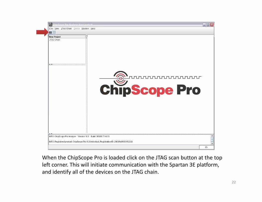
When the ChipScope Pro is loaded click on the JTAG scan button at the top left corner This will initiate communication with the Spartan 3E platformleft corner. This will initiate communication with the Spartan 3E platform, and identify all of the devices on the JTAG chain.
22
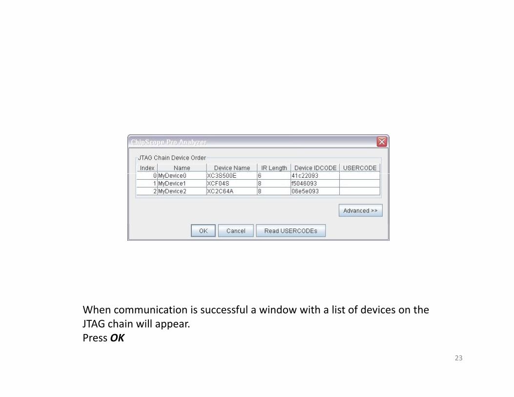
When communication is successful a window with a list of devices on the JTAG chain will appearJTAG chain will appear.Press OK
23
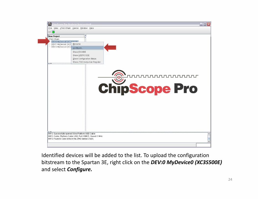
Identified devices will be added to the list. To upload the configuration bitstream to the Spartan 3E right click on the DEV:0 MyDevice0 (XC3S500E)bitstream to the Spartan 3E, right click on the DEV:0 MyDevice0 (XC3S500E)and select Configure.
24

Select configuration file from your project directory with extention .bit and press Openpress OpenPress OK to upload the configuration bitstream file.
25
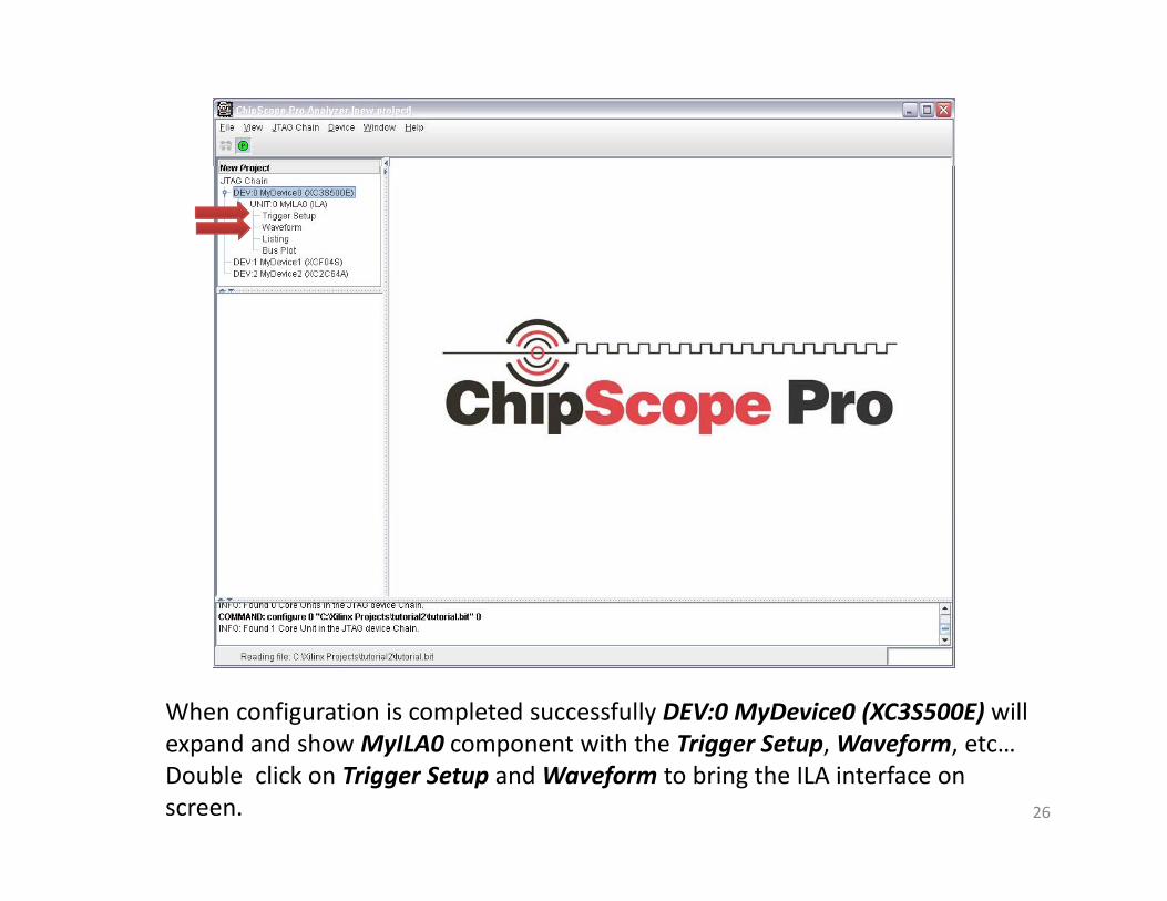
When configuration is completed successfully DEV:0 MyDevice0 (XC3S500E) will d d h 0 i h h i S fexpand and show MyILA0 component with the Trigger Setup, Waveform, etc…
Double click on Trigger Setup and Waveform to bring the ILA interface on screen. 26

3
1
2
1. Trigger Setup window allows to configure ChipScope Pro to commence capturing when combination of the particular signals is encounteredcapturing when combination of the particular signals is encountered. 2. Middle window shows the signal captures as it would on any logic analyzer.3. To initiate capture at any point, without trigger press on T! button.
27
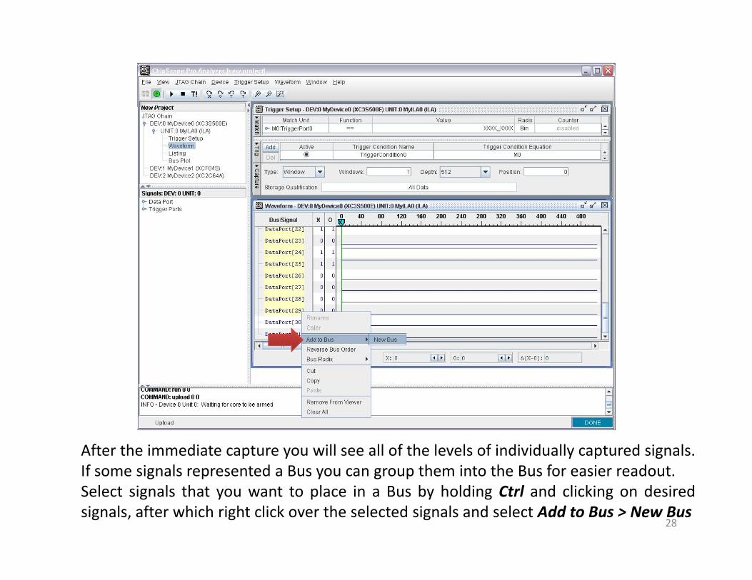
After the immediate capture you will see all of the levels of individually captured signals.If some signals represented a Bus you can group them into the Bus for easier readoutIf some signals represented a Bus you can group them into the Bus for easier readout.Select signals that you want to place in a Bus by holding Ctrl and clicking on desiredsignals, after which right click over the selected signals and select Add to Bus > New Bus
28

Grouped Bus will be added at the top of the list of signals. Grouped Bus can be renamed by right clicking on the Bus and selecting Renamebe renamed by right clicking on the Bus and selecting Rename.
29

There are several ways of representing grouped value. Options are available by right clicking on the bus and selecting Bus Radixmenu In this menu youby right clicking on the bus and selecting Bus Radix menu. In this menu you have many options such as Hex, Dec, Binary, and more.
30
21
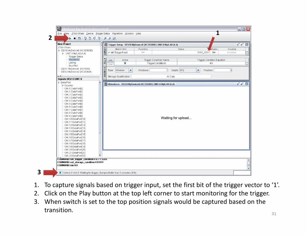
1. To capture signals based on trigger input, set the first bit of the trigger vector to ‘1’. 2 Click on the Play button at the top left corner to start monitoring for the trigger
3
2. Click on the Play button at the top left corner to start monitoring for the trigger.3. When switch is set to the top position signals would be captured based on the
transition. 31

As shown, when trigger (switch 0) was set to ‘1’ signals were captured and shown in the Waveform windowshown in the Waveform window.
32
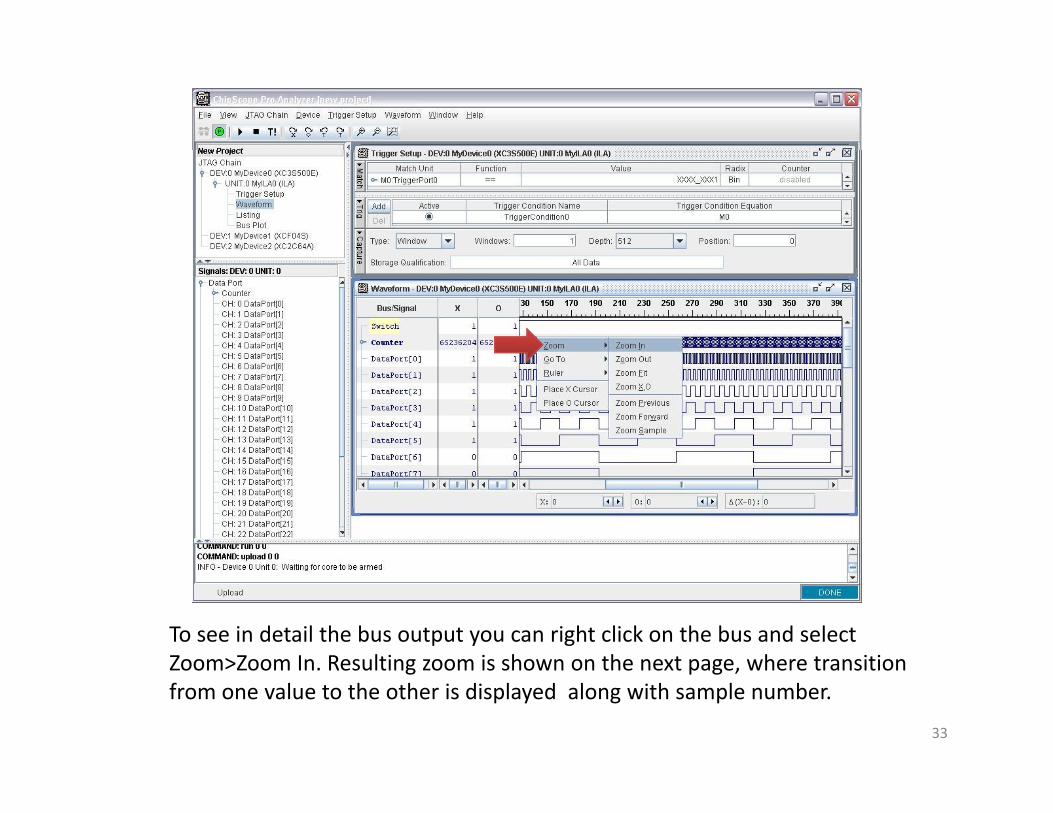
To see in detail the bus output you can right click on the bus and select Zoom>Zoom In Resulting zoom is shown on the next page where transitionZoom>Zoom In. Resulting zoom is shown on the next page, where transition from one value to the other is displayed along with sample number.
33
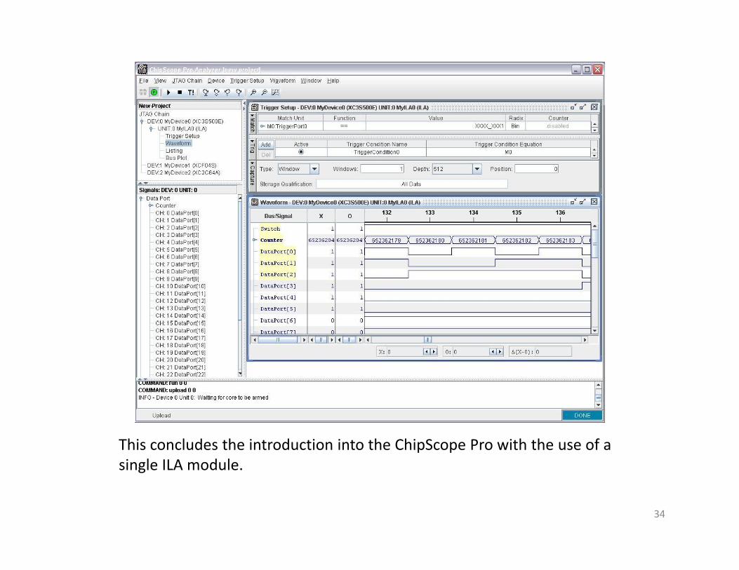
This concludes the introduction into the ChipScope Pro with the use of a single ILA modulesingle ILA module.
34
Conclusion
This complete ChipScope Pro tutorial which included:
•Overview of the ChipScope Pro•Generation of ChipScope Pro coresGeneration of ChipScope Pro cores•Insertion of ChipScope Pro cores into the project from Tutorial 1•Identification and Configuration of the FPGA device directly from ChipScope Pro•Capturing signals using ILA module and displaying in the Waveform window.C i i l b d h i•Capturing signals based on the trigger setup.
Next tutorial will cover the Virtual I/O module which allows for generation of virtual inputs and outputs inside the FPGA using the ChipScope Pro GUI. This p p g p pbenefits the designer on the stage of debugging of the firmware and hardware .
35