cobas h 232 POC system Operator’s Manual - Roche · Table of Contents 5 1 Introduction 9 The...
168
cobas h 232 POC system Operator’s Manual
Transcript of cobas h 232 POC system Operator’s Manual - Roche · Table of Contents 5 1 Introduction 9 The...

cobas h 232 POC systemOperator’s Manual
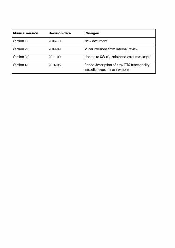
Manual version Revision date Changes
Version 1.0 2006-10 New document
Version 2.0 2009-09 Minor revisions from internal review
Version 3.0 2011-09 Update to SW 03; enhanced error messages
Version 4.0 2014-05 Added description of new OTS functionality, miscellaneous minor revisions
0 4880889001 (04) 2014-05 EN
cobas h 232 POC system
Operator’s Manual
Version 4.0
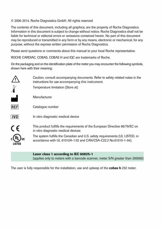
© 2006-2014, Roche Diagnostics GmbH. All rights reserved
The contents of this document, including all graphics, are the property of Roche Diagnostics. Information in this document is subject to change without notice. Roche Diagnostics shall not be liable for technical or editorial errors or omissions contained herein. No part of this document may be reproduced or transmitted in any form or by any means, electronic or mechanical, for any purpose, without the express written permission of Roche Diagnostics.
Please send questions or comments about this manual to your local Roche representative.
ROCHE CARDIAC, COBAS, COBAS H and IQC are trademarks of Roche.
On the packaging and on the identification plate of the meter you may encounter the following symbols, shown here with their meaning:
The user is fully responsible for the installation, use and upkeep of the cobas h 232 meter.
Caution, consult accompanying documents. Refer to safety-related notes in the instructions for use accompanying this instrument.
Temperature limitation (Store at)
Manufacturer
Catalogue number
In vitro diagnostic medical device
This product fulfills the requirements of the European Directive 98/79/EC on in vitro diagnostic medical devices
The system fulfills the Canadian and U.S. safety requirements (UL LISTED, in accordance with UL 61010A-1:02 and CAN/CSA-C22.2 No.61010-1-04).
Laser class 1 according to IEC 60825-1(applies only to meters with a barcode scanner, meter S/N greater than 200000)
IVD
Table of Contents
5
1 Introduction 9The cobas h 232 meter................................................................................................................... 9Test principle ..................................................................................................................................... 10Contents of the Pack ...................................................................................................................... 10
1.1 Important safety instructions and additional information......................................................... 11Safety information............................................................................................................................ 12Disposal of the system ................................................................................................................... 13General care....................................................................................................................................... 13Laser scanner .................................................................................................................................... 14Electrical safety ................................................................................................................................. 14Electromagnetic interference ...................................................................................................... 14Touchscreen....................................................................................................................................... 14Local Area Network: protection from unauthorized access ............................................ 15Wired network connection ........................................................................................................... 15
2 The cobas h 232 POC System 162.1 Overview of the meter and its accessories..................................................................................... 16
Meter ................................................................................................................................................... 16Test strip .............................................................................................................................................. 19Handheld Base Unit ........................................................................................................................ 20
3 Overview of the Buttons and Icons used on Screen 214 Putting the Meter into Operation 23
Power supply...................................................................................................................................... 24Inserting the handheld battery pack......................................................................................... 25Powering the meter on and off ................................................................................................... 27
5 Meter Setup 29Settings summary............................................................................................................................. 30
5.1 Basics setup ............................................................................................................................................... 35Contrast ............................................................................................................................................... 35Language ............................................................................................................................................ 37Setting the date................................................................................................................................. 39Setting the time................................................................................................................................. 41Setting the display options for date and time ....................................................................... 43Sound.................................................................................................................................................... 45Auto off ................................................................................................................................................ 48
5.2 Data Handling setup ............................................................................................................................... 50Connection ........................................................................................................................................ 50Computer............................................................................................................................................. 51Printer ................................................................................................................................................... 52Result memory .................................................................................................................................. 54Result unit ........................................................................................................................................... 57Result display mode........................................................................................................................ 59
5.3 ID Setup setting ........................................................................................................................................ 61Administrator ID ............................................................................................................................... 62Operator ID......................................................................................................................................... 68Patient ID............................................................................................................................................. 71

Table of Contents
6
5.4 Lockout setup ............................................................................................................................................ 73Operator lockout............................................................................................................................... 74Quality control (QC) settings ....................................................................................................... 77Quality control (QC) lockout ........................................................................................................ 79Instrument quality control (IQC) lockout................................................................................. 80QC result format ............................................................................................................................... 81Custom Range Troponin T ............................................................................................................ 82Reset test parameters..................................................................................................................... 84Cleaning lockout............................................................................................................................... 85STAT test configuration ................................................................................................................. 86
5.5 Optional Screens setup .......................................................................................................................... 886 Performing a Test 91
Sample material ................................................................................................................................ 926.1 Preparing to test ....................................................................................................................................... 93
Code chip ............................................................................................................................................ 93Inserting the code chip ................................................................................................................. 94Test steps (overview) ...................................................................................................................... 95Powering on the meter................................................................................................................... 96Logging in ........................................................................................................................................... 97
6.2 Performing a test ................................................................................................................................... 100Inserting a test strip .................................................................................................................... 104Displaying, confirming or adding comments to results.................................................. 109STAT tests ........................................................................................................................................ 112
7 Control Testing and Quality Control 1137.1 Preparing to run a quality control test .......................................................................................... 1137.2 Performing a quality control test ..................................................................................................... 115
Quality control (QC) ..................................................................................................................... 115Instrument quality control (IQC).............................................................................................. 121
8 Review Results 125Reviewing test results.................................................................................................................. 125Patient history ................................................................................................................................. 127All results.......................................................................................................................................... 128Quality control (QC) results....................................................................................................... 129Instrument quality control (IQC) results ............................................................................... 130Maintenance history .................................................................................................................... 131
9 Extended Functionalities 132Data handling ................................................................................................................................. 132Computer (Setup option)............................................................................................................ 133Operator lists................................................................................................................................... 134Patient lists....................................................................................................................................... 135Barcode scanner............................................................................................................................ 136Stored test results and comments .......................................................................................... 136
10 Cleaning and Disinfecting the Meter 139Recommended cleaning/disinfecting solutions ................................................................ 140Cleaning/disinfecting the exterior (meter housing) ......................................................... 140Cleaning after contamination due to mispipetting........................................................... 141Cleaning the test strip guide cover......................................................................................... 142Cleaning the visible area of the test strip guide................................................................ 143

Table of Contents
7
11 Troubleshooting 145Errors and unusual behavior without error messages .................................................... 146
12 General Product Specifications 14712.1 Operating conditions and technical data..................................................................................... 147
Technical data ................................................................................................................................ 147Sample material ............................................................................................................................. 148Storage and transport conditions ........................................................................................... 148
12.2 Further information............................................................................................................................... 148Ordering information ................................................................................................................... 148Product limitations........................................................................................................................ 150Information about software licenses .................................................................................... 150Repairs .............................................................................................................................................. 150Contact Roche................................................................................................................................ 150
13 Warranty 15014 Appendix 151
14.1 Example of barcode symbologies ................................................................................................... 15114.2 Contact Roche ...................................................................................................................................... 152
15 Supplement for Observed Test Sequence 159Observed Test Sequence (OTS) ............................................................................................. 159Using the OTS function............................................................................................................... 160
16 Index 163

Table of Contents
8
This page intentionally left blank.

Introduction
9
1 Introduction
The cobas h 232 meter
The cobas h 232 meter is an instrument for the quantitative evaluation of immunoassays using the gold-labeling technique. The rapid diagnostic tests in strip format available for this meter support efficient diagnosis and assessment of cardiovascular diseases. The evaluation of these tests with the cobas h 232 meter combines the advantages of a rapid diagnosis with enhanced clinical interpretation of quantitative values (in comparison with qualitative tests). In addition, automated evaluation provides more reliable results by eliminating the potential sources of error associ-ated with visual reading. Refer to the package inserts accompanying the test strips for detailed information on specific tests.
Readings may be carried out directly where the blood samples are taken. Therefore, the cobas h 232 meter is ideal for use at the point of care in emergency rooms, intensive care units and ambulances, as well as by cardiologists and general practitioners. The cobas h 232 meter is rapid and easy to operate: Insert an unused strip in the meter and apply the sample. After the reaction period, the meter provides a quantitative result; in addition, a qualitative result is pro-vided prior to the end of some tests.
The cobas h 232 meter has the ability to connect to a data management system (DMS) through the Handheld Base Unit from Roche (available separately). The cobas h 232 meter supports data exchange via the POCT1A standard. Data management systems may have the ability to expand the security features of the meter, such as enabling operator lockouts. Data management sys-tems may also enable data transfer to an LIS or HIS. Refer to the manuals of the Handheld Base Unit and of your DMS for technical details.
Read this operator's manual, as well as the package inserts for all relevant consumables, before using the system for the first time. You must configure the cobas h 232 meter according to your needs before initial use. Refer to Chapter 5, “Meter Setup”. Be sure to read the “Important safety instructions and additional information” section in this chapter before operating the system.
For all questions about the cobas h 232 system that are not answered in this manual, contact your Roche representative (see Chapter 12). In order to expedite troubleshooting, please have ready your cobas h 232 meter, its serial number, this manual, and all related consumables when you call.
If you connect your cobas h 232 meter to a cobas IT 1000 data management system or another PC/DMS, you will not be able to print directly from the meter to a printer. In order to print out meter data, use printers connected to the respective PC/DMS.

Introduction
10
Test principle
Two lines (signal and control line) in the detection zone of the test strip indicate whether the analyte to be determined is present in the sample material. These lines are detected by the cobas h 232 meter with the help of an LED (lighting the detection zone) and a camera sensor (imaging the detection zone). The test signal (signal line) increases in intensity in proportion to the concentration of the respective analyte. Integrated system software converts the signal intensity to a quantitative result, which is then displayed on the screen at the end of the measurement.
The accuracy of the measurement is ensured through a simple principle: Every test strip box includes a code chip that contains all test and lot-specific information in electronic format. The test strips are labelled with a barcode on their underside and are hereby assigned to a specific code chip. When you insert a test strip from a new strip lot for the first time, the meter prompts you to plug in the corresponding code chip. The information is now read from the code chip and stored for future tests.
Contents of the Pack
■ cobas h 232 meter
■ Handheld power supply with cable
■ Operator’s manual in English
■ CD-ROM with operator’s manual in other languages
Optionally available (not included in the scope of delivery):
■ Roche Handheld Battery Pack (rechargeable) for temporary operation without the hand-held power supply
■ Handheld Base Unit (docking station) for data transfer within a network or via USB (Universal Serial Bus)
For a personal printout of the operator’s manual in your language, contact your local Roche organization (see Chapter 14).
Introduction
11
1.1 Important safety instructions and additional information
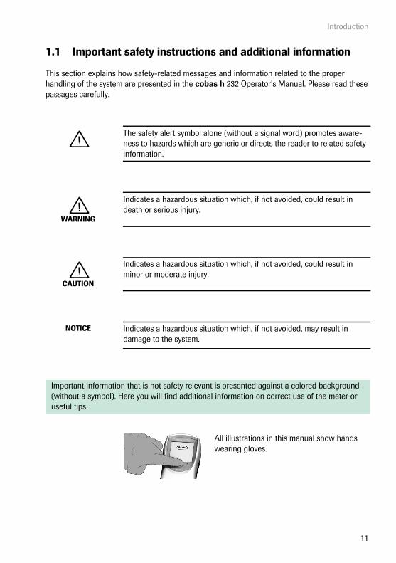
This section explains how safety-related messages and information related to the proper handling of the system are presented in the cobas h 232 Operator’s Manual. Please read these passages carefully.
The safety alert symbol alone (without a signal word) promotes aware-ness to hazards which are generic or directs the reader to related safety information.
WARNING
Indicates a hazardous situation which, if not avoided, could result in death or serious injury.
CAUTION
Indicates a hazardous situation which, if not avoided, could result in minor or moderate injury.
NOTICE Indicates a hazardous situation which, if not avoided, may result in damage to the system.
Important information that is not safety relevant is presented against a colored background (without a symbol). Here you will find additional information on correct use of the meter or useful tips.
All illustrations in this manual show hands wearing gloves.
Introduction
12
Safety information
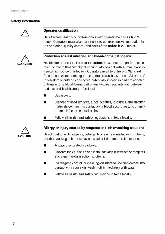
Operator qualification
Only trained healthcare professionals may operate the cobas h 232 meter. Operators must also have received comprehensive instruction in the operation, quality control, and care of the cobas h 232 meter.
WARNING
Protection against infection and blood-borne pathogens
Healthcare professionals using the cobas h 232 meter to perform tests must be aware that any object coming into contact with human blood is a potential source of infection. Operators need to adhere to Standard Precautions when handling or using the cobas h 232 meter. All parts of this system should be considered potentially infectious and are capable of transmitting blood-borne pathogens between patients and between patients and healthcare professionals.
■ Use gloves.
■ Dispose of used syringes, tubes, pipettes, test strips, and all other materials coming into contact with blood according to your insti-tution’s infection control policy.
■ Follow all health and safety regulations in force locally.
CAUTION
Allergy or injury caused by reagents and other working solutions
Direct contact with reagents, detergents, cleaning/disinfection solutions, or other working solutions may cause skin irritation or inflammation.
■ Always use protective gloves.
■ Observe the cautions given in the package inserts of the reagents and cleaning/disinfection solutions.
■ If a reagent, control, or cleaning/disinfection solution comes into contact with your skin, wash it off immediately with water.
■ Follow all health and safety regulations in force locally.
Introduction
13
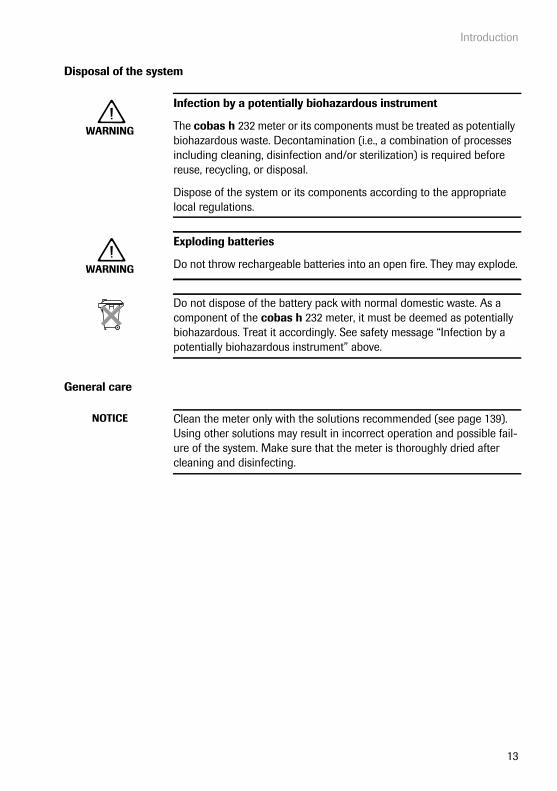
Disposal of the system
General care
WARNING
Infection by a potentially biohazardous instrument
The cobas h 232 meter or its components must be treated as potentially biohazardous waste. Decontamination (i.e., a combination of processes including cleaning, disinfection and/or sterilization) is required before reuse, recycling, or disposal.
Dispose of the system or its components according to the appropriate local regulations.
WARNING
Exploding batteries
Do not throw rechargeable batteries into an open fire. They may explode.
Do not dispose of the battery pack with normal domestic waste. As a component of the cobas h 232 meter, it must be deemed as potentially biohazardous. Treat it accordingly. See safety message “Infection by a potentially biohazardous instrument” above.
NOTICE Clean the meter only with the solutions recommended (see page 139). Using other solutions may result in incorrect operation and possible fail-ure of the system. Make sure that the meter is thoroughly dried after cleaning and disinfecting.
Introduction
14
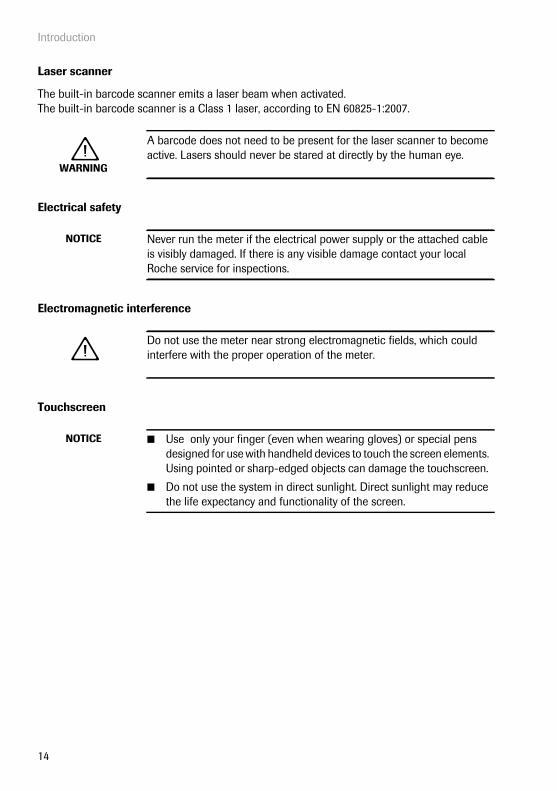
Laser scanner
The built-in barcode scanner emits a laser beam when activated.The built-in barcode scanner is a Class 1 laser, according to EN 60825-1:2007.
Electrical safety
Electromagnetic interference
Touchscreen
WARNING
A barcode does not need to be present for the laser scanner to become active. Lasers should never be stared at directly by the human eye.
NOTICE Never run the meter if the electrical power supply or the attached cable is visibly damaged. If there is any visible damage contact your local Roche service for inspections.
Do not use the meter near strong electromagnetic fields, which could interfere with the proper operation of the meter.
NOTICE ■ Use only your finger (even when wearing gloves) or special pens designed for use with handheld devices to touch the screen elements. Using pointed or sharp-edged objects can damage the touchscreen.
■ Do not use the system in direct sunlight. Direct sunlight may reduce the life expectancy and functionality of the screen.
Introduction
15
Local Area Network: protection from unauthorized access
If this product is connected to a local area network, this network must be protected against unauthorized access. In particular, it must not be linked directly to any other network or the Inter-net. Customers are responsible for the security of their local area network, especially in protect-ing it against malicious software and attacks. This protection might include measures, such as a firewall, to separate the device from uncontrolled networks as well as measures that ensure that the connected network is free of malicious code.
Wired network connection
If connected to a local area network, the cobas h 232 Handheld Base Unit must be protected against unauthorized access by means of a strong password management. Observe your own facility guidelines on password management where available, or apply the following rules:
Characteristics of strong passwords
■ Passwords must not contain the user’s account name or parts of the user’s full name that exceed two consecutive characters.
■ Passwords must be at least eight characters in length.
■ Passwords must contain characters from at least three of the following four categories:
– English uppercase alphabetic characters (A through Z)– English lowercase alphabetic characters (a through z)– Numeric characters (0 through 9)– Non-alphabetic characters (for example, !, $, #, %)
Examples of weak passwords
■ uhxwze11 contains no upper case letter.
■ UHXW13SF contains no lower case letter.
■ uxxxxx7F contains the same character more than four times.
■ x12useridF contains a substring of the user ID longer than four characters.
To ensure that your cobas h 232 meter functions properly, observe the operating and storage conditions as given in the chapter “General Product Specifications”, starting on page 147.
The cobas h 232 POC System
16
2 The cobas h 232 POC System
2.1 Overview of the meter and its accessories
Meter
AB
D
E
C
G
CLASS I LASER PRODUCT
Complies with 21 CFR 1040.10
and 1040.11 except for deviations pursuant to Laser
Notice No. 50, dated July 26, 2001
H
F
I

The cobas h 232 POC System
17
A TouchscreenShows results, information, icons and results saved in the memory. To select an option, simply touch the button lightly.
B On/Off buttonPress this button to power the meter on or off.
C Opening for sample applicationOpening in the test strip guide cover that enables you to apply blood once the test strip is inserted.
D Test strip guide coverRemove this cover to clean the area underneath (if it has become soiled, e.g., with blood).
E Barcode scanner (Laser)Operator and patient IDs can be read into the meter using the integrated barcode scanner (only meter versions with a serial number greater than 200 000).
F Battery compartmentA cover closes the empty battery com-partment if meter is operated without the Handheld Battery Pack; alternatively insert battery pack.
G Tab of the battery compartment coverUsed to open the battery compartment.
H Meter identification plateSee page 4 for symbol explanation.
I Laser labelFor meters with a barcode scanner only.

The cobas h 232 POC System
18
J Test strip guideInsert the test strip here.
K Reset buttonUse this button to reset the meter in case of software or power-up errors.
L Infrared (IR) window Supports data communication (covered by the semi-transparent rear panel).
M Code chip slotInsert the code chip here.
N Contacts for Handheld Base UnitUsed for power supply and/or charging the handheld battery pack, when the meter is docked in the Handheld Base Unit.
O Connection socket for thepower supply unitHere you can plug in the power supply unit provided.
M
J
O
L
N
K
The cobas h 232 POC System
19
Test strip
P Test areaThis area is evaluated by the meter via the camera.
Q Sample application areaThe sample is applied to this area after inserting the test strip in the meter.
R BarcodeAssigns the strip to the corresponding code chip. The barcode is automatically read by the meter when the strip is inserted into the test strip guide.
S Code chipContains strip lot specific data.
R
P
QS
The cobas h 232 POC System
20
Handheld Base Unit
T Charging contactsUsed for power supply and/or charging the handheld battery pack.
U Status indicator Lights up when power is connected, charge indicator.
V Infrared (IR) windowFor communication with the meter.
W Extension piece For cobas h 232 meter.
X Data ports (Ethernet/RJ45 and USB)For connecting the device to a Data Management System (DMS).
Y Connection socket for thepower supply unitHere you can plug in the power supply unit provided with the meter.
Z Removable cover for configuration switchThe switch sets the mode of operation for the Handheld Base Unit.
The Handheld Base Unit can be ordered separately. For detailed information on usage and configuration please consult the operator's manual of the Handheld Base Unit and the Technical Note stored on the Handheld Base Unit itself.
T
U
V
Y
Z
W
X

Overview of the Buttons and Icons used on Screen
21
3 Overview of the Buttons and Icons used on Screen
The buttons and icons that appear during normal operation are shown here, along with a general explanation. Error messages and the description of the icons linked to them are provided in a separate chapter. See “Troubleshooting” starting on page 145.
Button/Icon Meaning
OK, save setting
Cancel, discard setting
Return (to previous menu)
Decrease/increase a numeric value orScroll through lists that are too long to be displayed at once
Inactive button; value cannot be further decreased/increased orEnd of list in this direction is reached
Return to the Main Menu screen
List of tests of an individual patient
Scroll through stored results
Print displayed result (via infrared interface to corresponding printer)
Add a comment
Operator logout
Operator login
Operator must wait until the meter has completed an action.
Insert test strip
Remove test strip
Test strip warming up
Apply sample (the time left to apply sample is counted down in the screen alongside the required sample amount)
Apply QC sample (the time left to apply sample is counted down in the screen alongside the required sample amount)
Overview of the Buttons and Icons used on Screen
22
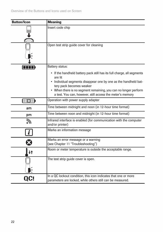
Insert code chip
Open test strip guide cover for cleaning
Battery status:
• If the handheld battery pack still has its full charge, all segments are lit
• Individual segments disappear one by one as the handheld bat-tery pack becomes weaker
• When there is no segment remaining, you can no longer perform a test. You can, however, still access the meter’s memory
Operation with power supply adapter
Time between midnight and noon (in 12-hour time format)
Time between noon and midnight (in 12-hour time format)
Infrared interface is enabled (for communication with the computer and/or printer)
Marks an information message
Marks an error message or a warning (see Chapter 11 “Troubleshooting”)
Room or meter temperature is outside the acceptable range.
The test strip guide cover is open.
In a QC lockout condition, this icon indicates that one or more parameters are locked, while others still can be measured.
Button/Icon Meaning
am
pm
QC!

Putting the Meter into Operation
23
4 Putting the Meter into Operation
Before using the meter for the first time, perform the following steps:
1 Connect the handheld power supply
2 If present, insert the handheld battery pack for recharging (see page 25)
3 Set the current date and time as well as the appropriate display format (see Chapter “Meter Setup” starting on page 29)
4 Enter the settings of choice (language, quality controls – where necessary, user administration, etc.)
If the meter has no date/time settings (either because you are powering on the meter for the first time or because the handheld battery pack was removed from the meter for more than 24 hours), you cannot perform a test (see page 24 “Power supply”). In that case powering on the meter takes you immediately to the Setup mode, where you must set the date and time. See “Setting the date” on page 39 and “Setting the time” on page 41.

Putting the Meter into Operation
24
Power supply
The meter can be operated with either the handheld power supply (adapter/charger) provided, the (optional) Handheld Base Unit or the (optional) handheld battery pack. It is advisable to insert the handheld battery pack even when you use the handheld power supply. This ensures that you do not lose the date and time settings (in case of a power outage or if the local power supply is shut off). Results are retained in the memory together with the corresponding date and time, as well as all other settings, even when no handheld battery pack is inserted.
To save power, the meter can automatically power itself off after a programmable period of time, if no buttons are pressed or new test strips are inserted. When the meter powers itself off, all test results obtained up to that point remain in memory and the settings are retained (see “Auto off” in the chapter entitled “Data Handling setup” on page 48).
During battery operation, the meter always displays the power level of the handheld battery pack. The battery icon is divided into four segments which correspond to the bat-tery power level.
When replacing the batteries you must insert the new handheld battery pack within ten (10) minutes of removing the old one, to retain the date and time settings. If you take longer than this, you must re-enter the date and time.
To make certain you do not lose your date and time settings, connect the handheld power supply unit while you change the handheld battery pack.
Dispose of used battery packs in an environmentally responsible manner in accordance with applicable local regulations and directives. See “Infection by a potentially biohazardous instrument” on page 13.
Main Menu
Control Test
Review Results
Setup
Patient Test
Logout
09:15 am
04/19/2014

Putting the Meter into Operation
25
Inserting the handheld battery pack
1 With the meter powered off, hold it so that the tab on the handheld battery pack points upward.
2 Gently press the tab on the battery com-partment cover towards the center of the meter and tilt the cover to the side.
3 Slide the battery compartment cover upward and remove it.
Note: The battery compartment cover is no longer needed, once you insert a handheld battery pack.

Putting the Meter into Operation
26
With a fully charged battery, up to 10 tests can be performed. This includes samples, QC and meter controls.
4 Insert the handheld battery pack as indi-cated in the battery compartment.
Use only the specially-designed handheld battery pack.
5 Close the battery compartment. The meter powers itself on after a (charged) handheld battery pack has been inserted. If you insert an uncharged or partially charged handheld battery pack, it can only be charged by connect-ing the handheld power supply.
If the settings for date and time have not yet been set or if they have been lost (because the meter was without power for more than ten minutes), your cobas h 232 meter automatically switches to Setup mode when power is restored. You must enter the date and time, then the meter automatically switches to the Main Menu.
After installing a new battery pack, the meter should be charged for four hours before testing.
Putting the Meter into Operation
27
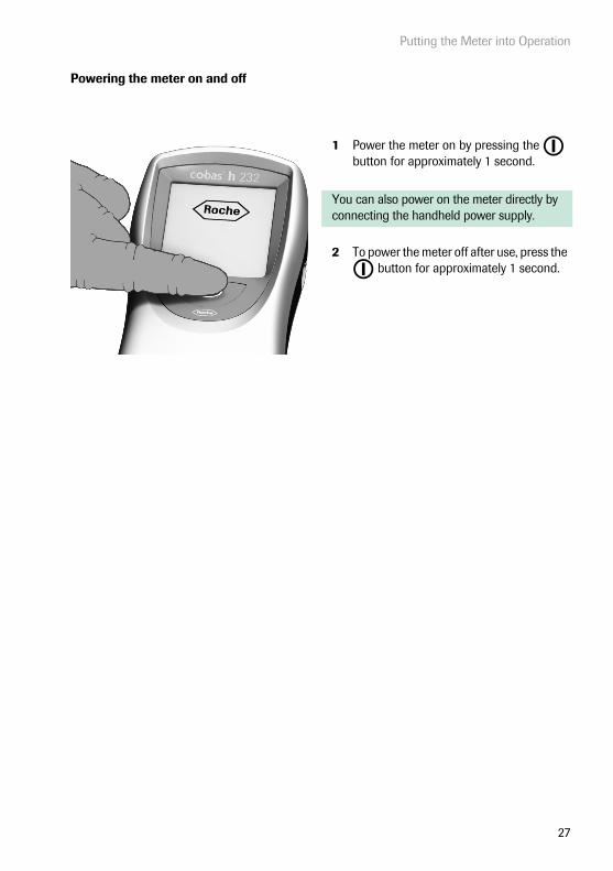
Powering the meter on and off
1 Power the meter on by pressing the button for approximately 1 second.
You can also power on the meter directly by connecting the handheld power supply.
2 To power the meter off after use, press the button for approximately 1 second.

Putting the Meter into Operation
28
This page intentionally left blank.

Meter Setup
29
5 Meter Setup
Buttons are screen prompts that cause something to happen when touched. The names of all buttons are either shown as bold text or as the icon used on the button (e.g., for OK ).
Other screen elements (e.g., Menu titles) are written in italics. These screen elements are not active.
You can open any displayed function by touching (or tapping) the button for it with your finger (or a special pen for this purpose). “Tap” means: Touch the button, then remove your finger from the touchscreen. The next screen appears once you remove your finger.
1 Touch Setup to call up the Setup menu.
2 Select the group of settings of choice (see the Settings summary following this section).
For a description of the buttons and icons used on screen see page 21.
Data Handling
ID Setup
Lockout
Basics
Optional Screens
Setup
04/19/2014
Main Menu
Control Test
Review Results
Setup
Patient Test
04/19/2014
09:15 am

Meter Setup
30
Settings summary
The diagram below gives an overview of the setup areas that can be accessed on the meter.
Setup
Data Handling
ID Setup
Basics
LanguageContrast
Connection
Administrator ID
Operator Lockout
Start Info
Date/Time
QC Settings
Result Login
Sound
Operator ID
Cleaning Lockout
Result Confi rmation
Auto Off
Result Memory
Patient ID
STAT Test Confi g.
Lockout
Optional Screens
Result Display ModeDD Result Unit

Meter Setup
31
* Default settings are labelled with an asterisk (*).
Group Subgroup Setting Values *Basics Contrast 0 – 10 (5*)
Language Dansk
Deutsch
English *
Español
Français
Italiano
Nederlands
Norsk
Português
Svenska
An installable language
Date/Time Date 01/01/2011 *
Time 12:00 am *
Date formats Day.Month.Year (31.12.2011)
Month/Day/Year (12/31/2011) *
Year-Month-Day (2011-12-31)
Time formats 24-hour time format (24H)
12-hour time format (12H), with am/pm *
Sound (Beeper) Volume Off
Low
Medium *
High
Key Click Enable
Disable *
Auto Off [minutes] Off
1 … 10 (default: 5 min *)
15, 20, 25, 30
40, 50, 60

Meter Setup
32
* Default settings are labelled with an asterisk (*).
Group Subgroup Setting Values *Data Handling Connection Off *
Computer
Printer
Result Memory Result Display Filter All results *
Current Op. Res.
Result Storage Mode
No results deletion *
Delete oldest result
DD Result Unit μg/mL *
ng/mL
mg/L
μg/L
Result Display Mode Static *
Flashing
ID Setup Administrator ID Blank (off) *
Operator ID None *
Optional
Required
Scan Only
Patient ID None
Optional *
Required
Hidden List

Meter Setup
33
* Default settings are labelled with an asterisk (*).
Group Subgroup Setting Values *Lockout Operator Lockout (only if “Operator ID”
option is enabled)No *
Daily
Weekly
Monthly
Every 3 months
Every 6 months
Yearly
QC Settings QC Lockout New Lot: Yes/No *
No *
Daily
Weekly
Monthly
IQC Lockout No *
Daily
Weekly
Monthly
QC Result Format Pass/Fail *
Value
Value & Pass/Fail
Custom Range Trop T
Default Range*
Custom Range
Reset Test Param. Do Reset
No Reset *
Cleaning Lockout No *
Daily
Weekly
Monthly
STAT Test Config. Enable
Disable *
Meter Setup
34
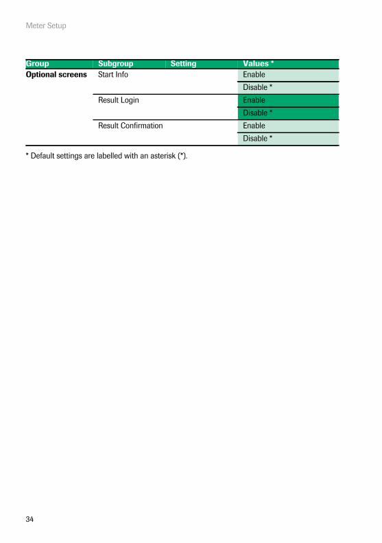
* Default settings are labelled with an asterisk (*).
Group Subgroup Setting Values *Optional screens Start Info Enable
Disable *
Result Login Enable
Disable *
Result Confirmation Enable
Disable *

Meter Setup
35
5.1 Basics setup
The Basics setup area contains the basic options for changing the user interface.
Contrast
Use the Contrast menu to adjust the display to your ambient light conditions and make it easier to read.
1 From the Main Menu, touch Setup to open the meter settings.
2 From the Setup menu, touch Basics.
3 From the Setup-Basics menu, touch Contrast.
Main Menu
Control Test
Review Results
Setup
Patient Test
04/19/2014
09:15 am
Data Handling
ID Setup
Lockout
Basics
Optional Screens
Setup
04/19/2014Language
Date/Time
Sound
Contrast
Auto Off
Setup - Basics
04/19/2014

Meter Setup
36
4 Touch or to change the contrast in a range from 0 to 10.
■ Contrast “0” makes the screen very dark.
■ Contrast “10” makes the screen very light.
5 Touch to save this setting, or:
Touch to exit this menu without saving any changes.The display automatically returns to the previous screen.
Select Contrast
Contrast:(0-10) 5
04/19/2014
Meter Setup
37
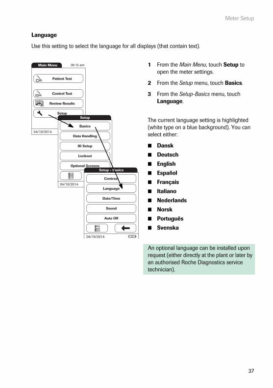
Language
Use this setting to select the language for all displays (that contain text).
1 From the Main Menu, touch Setup to open the meter settings.
2 From the Setup menu, touch Basics.
3 From the Setup-Basics menu, touch Language.
The current language setting is highlighted (white type on a blue background). You can select either:
■ Dansk
■ Deutsch
■ English
■ Español
■ Français
■ Italiano
■ Nederlands
■ Norsk
■ Português
■ Svenska
An optional language can be installed upon request (either directly at the plant or later by an authorised Roche Diagnostics service technician).
Main Menu
Control Test
Review Results
Setup
Patient Test
04/19/2014
09:15 am
Data Handling
ID Setup
Lockout
Basics
Optional Screens
Setup
04/19/2014Language
Date/Time
Sound
Contrast
Auto Off
Setup - Basics
04/19/2014
Meter Setup
38
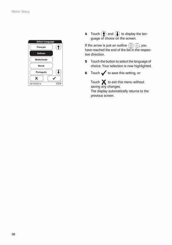
4 Touch and to display the lan-guage of choice on the screen.
If the arrow is just an outline , you have reached the end of the list in the respec-tive direction.
5 Touch the button to select the language of choice. Your selection is now highlighted.
6 Touch to save this setting, or:
Touch to exit this menu without saving any changes.The display automatically returns to the previous screen.
Français
Italiano
Nederlands
Norsk
Português
Select Language
04/19/2014

Meter Setup
39
Setting the date
Use this menu to set the date of the meter.
1 From the Main Menu, touch Setup to open the meter settings.
2 From the Setup menu, touch Basics.
3 From the Setup-Basics menu, touch Date/Time.
Main Menu
Control Test
Review Results
Setup
Patient Test
04/19/2014
09:15 am
Data Handling
ID Setup
Lockout
Basics
Optional Screens
Setup
04/19/2014Language
Date/Time
Sound
Contrast
Auto Off
Setup - Basics
04/19/2014
Meter Setup
40
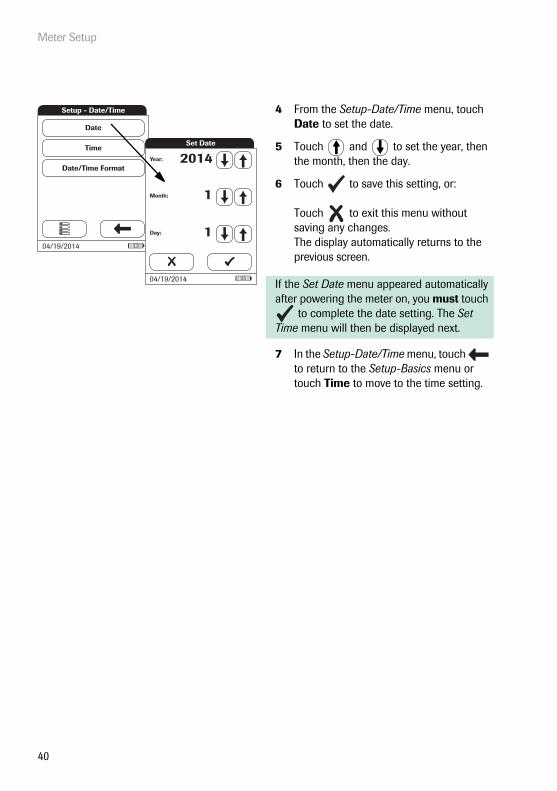
4 From the Setup-Date/Time menu, touch Date to set the date.
5 Touch and to set the year, then the month, then the day.
6 Touch to save this setting, or:
Touch to exit this menu without saving any changes.The display automatically returns to the previous screen.
If the Set Date menu appeared automatically after powering the meter on, you must touch
to complete the date setting. The Set Time menu will then be displayed next.
7 In the Setup-Date/Time menu, touch to return to the Setup-Basics menu or touch Time to move to the time setting.
Setup - Date/Time
Time
Date/Time Format
Date
04/19/2014
Set Date
Month: 1
Day: 1
Year: 2014
04/19/2014
Meter Setup
41
Setting the time
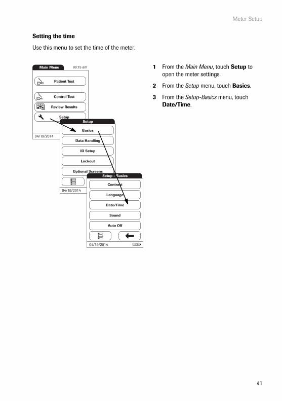
Use this menu to set the time of the meter.
1 From the Main Menu, touch Setup to open the meter settings.
2 From the Setup menu, touch Basics.
3 From the Setup-Basics menu, touch Date/Time.
Main Menu
Control Test
Review Results
Setup
Patient Test
04/19/2014
09:15 am
Data Handling
ID Setup
Lockout
Basics
Optional Screens
Setup
04/19/2014Language
Date/Time
Sound
Contrast
Auto Off
Setup - Basics
04/19/2014
Meter Setup
42
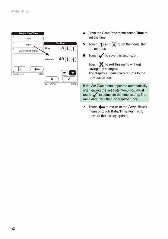
4 From the Date/Time menu, touch Time to set the time.
5 Touch and to set the hours, then the minutes.
6 Touch to save this setting, or:
Touch to exit this menu without saving any changes.The display automatically returns to the previous screen.
If the Set Time menu appeared automatically after leaving the Set Date menu, you must touch to complete the time setting. The Main Menu will then be displayed next.
7 Touch to return to the Setup-Basics menu or touch Date/Time Format to move to the display options.
Setup - Date/Time
Time
Date/Time Format
Date
04/19/2014
Minutes: 49
Hour: 3Set Time
04/19/2014
AM PM

Meter Setup
43
Setting the display options for date and time
Select your preferred format for the date and time display.
1 From the Main Menu, touch Setup to open the meter settings.
2 From the Setup menu, touch Basics.
3 From the Setup-Basics menu, touch Date/Time.
Main Menu
Control Test
Review Results
Setup
Patient Test
04/19/2014
09:15 am
Data Handling
ID Setup
Lockout
Basics
Optional Screens
Setup
04/19/2014Language
Date/Time
Sound
Contrast
Auto Off
Setup - Basics
04/19/2014
Meter Setup
44
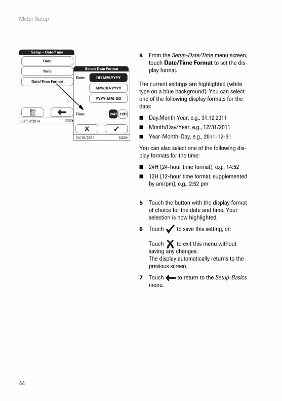
4 From the Setup-Date/Time menu screen, touch Date/Time Format to set the dis-play format.
The current settings are highlighted (white type on a blue background). You can select one of the following display formats for the date:
■ Day.Month.Year, e.g., 31.12.2011
■ Month/Day/Year, e.g., 12/31/2011
■ Year-Month-Day, e.g., 2011-12-31
You can also select one of the following dis-play formats for the time:
■ 24H (24-hour time format), e.g., 14:52
■ 12H (12-hour time format, supplemented by am/pm), e.g., 2:52 pm
5 Touch the button with the display format of choice for the date and time. Your selection is now highlighted.
6 Touch to save this setting, or:
Touch to exit this menu without saving any changes.The display automatically returns to the previous screen.
7 Touch to return to the Setup-Basics menu.
Setup - Date/Time
Time
Date/Time Format
Date
04/19/2014
Select Date Format
Date: DD.MM.YYYY
MM/DD/YYYY
YYYY-MM-DD
Time: 24H 12H
04/19/2014

Meter Setup
45
Sound
The cobas h 232 meter can display information visually and alert you to special circumstances with a beep sound. When the Sound is activated, the meter beeps when:
■ it is powered on
■ it detects a test strip
■ pre-heating of the test strip is complete and you need to apply a sample
■ the test is completed and the results are displayed (a long beep)
■ an error occurs (three short beeps)
■ the handheld power supply unit is connected when the meter is on
■ a barcode is scanned successfully (short beep)
■ the barcode scanner is disabled (two short beeps)
■ a positive test result can be expected, while the measurement still is in progress (a long beep)
You can also activate a Key Click. When the Key Click is activated, the meter clicks briefly every time a button is touched, facilitating the input of information.
We recommend that you keep the Sound (beeper) activated at all times.

Meter Setup
46
1 From the Main Menu, touch Setup to open the meter settings.
2 From the Setup menu, touch Basics.
3 From the Setup-Basics menu, touch Sound.
Main Menu
Control Test
Review Results
Setup
Patient Test
04/19/2014
09:15 am
Data Handling
ID Setup
Lockout
Basics
Optional Screens
Setup
04/19/2014Language
Date/Time
Sound
Contrast
Auto Off
Setup - Basics
04/19/2014

Meter Setup
47
4 From the Setup-Sound menu, touch Volume to set the volume level of the beeper.
The current setting is highlighted (white type on a blue background). You may select from the following options:
■ Off
■ Low
■ Medium
■ High
5 Touch Key Click in the Setup-Sound menu to turn the key click on or off.
You may select from the following options:
■ Enable
■ Disable
6 Touch to save this setting, or:
Touch to exit this menu without saving any changes.The display automatically returns to the previous screen.
7 Touch to return to the Setup-Basics menu.
Disable
Enable
Key Click
04/19/2014
Key Click
Volume
Setup - Sound
04/19/2014
Off
Low
Medium
High
Select Volume
04/19/2014

Meter Setup
48
Auto off
You can set up your meter so that it powers itself off automatically if it has not been used (no buttons touched or tests run) for a preselected time period. Use this feature to save power and extend the life of the batteries.
1 From the Main Menu, touch Setup to open the meter settings.
2 From the Setup menu, touch Basics.
3 In the Setup-Basics menu, touch Auto Off.
If the meter is connected to the handheld power supply or the Handheld Base Unit, the Auto Off function has a different effect:
■ If you do not work with operator IDs, the meter switches to the Main Menu, once Auto Off is triggered.
■ If you work with operator IDs, the meter switches to Operator Login, once Auto Off is triggered.
For information on Operator ID, see “Operator ID” on page 68.
Main Menu
Control Test
Review Results
Setup
Patient Test
04/19/2014
09:15 am
Data Handling
ID Setup
Lockout
Basics
Optional Screens
Setup
04/19/2014Language
Date/Time
Sound
Contrast
Auto Off
Setup - Basics
04/19/2014

Meter Setup
49
You may select from the following options:
■ Off (meter never powers itself off)
■ Time until meter powers itself off:1…10, 15, 20, 25, 30, 40, 50, 60 minutes
4 Touch and to select the time of choice in minutes or to deactivate the feature.
5 Touch to save this setting, or:
Touch to exit this menu without saving any changes.The display automatically returns to the previous screen.
6 Touch to return to the Setup menu.
Set Auto Off Time
Minutes: 5
04/19/2014
Meter Setup
50
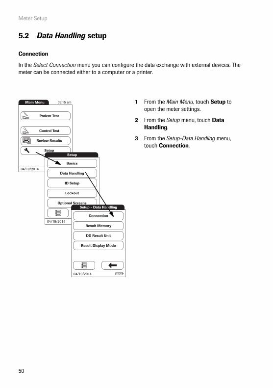
5.2 Data Handling setup
Connection
In the Select Connection menu you can configure the data exchange with external devices. The meter can be connected either to a computer or a printer.
1 From the Main Menu, touch Setup to open the meter settings.
2 From the Setup menu, touch Data Handling.
3 From the Setup-Data Handling menu, touch Connection.
Main Menu
Control Test
Review Results
Setup
Patient Test
04/19/2014
09:15 am
Data Handling
ID Setup
Lockout
Basics
Optional Screens
Setup
04/19/2014Result Memory
DD Result Unit
Result Display Mode
Setup - Data Handling
Connection
04/19/2014

Meter Setup
51
Computer
The cobas h 232 meter can connect with a computer or host system running appropriate soft-ware (that is, a DMS must be installed). To use this connectivity feature, however, you need the optional Handheld Base Unit. The connection is established in two steps.
■ The meter connects to the Handheld Base Unit via infrared.
■ The Handheld Base Unit is either connected to a single computer (via USB) or to a net-work/host system (via Ethernet).
The option Computer (when activated) can be used together with a DMS to set up:
■ operator lists, or
■ patient lists (lists of patients to be tested)
This eliminates the need for manual entry of these data. In addition, you can transfer test results stored in the meter to other systems for archiving or further evaluation. The option Computer controls the meter’s ability to communicate with a computer or a network.
4 Touch Computer. Your selection is now highlighted.
5 Touch to save this setting, or:
Touch to exit this menu without saving any changes.The display automatically returns to the previous screen.
Extended data handling functionality is dependent on the capabilities of the particular Data Management System (DMS) being used and may vary.
Off
Computer
Printer
Select Connection
04/19/2014

Meter Setup
52
Printer
The meter can connect directly with three different infrared printers. The Handheld Base Unit cannot be used for this purpose.
The option to print is displayed in a test result as well as directly after a test and when calling up stored results. Using the settings you enter here, you can activate or deactivate the meter‘s ability to print.
1 From the Main Menu, touch Setup to open the meter settings.
2 From the Setup menu, touch Data Handling.
3 From the Setup-Data Handling menu, touch Connection.
Connection to a printer can only be established via infrared.
Main Menu
Control Test
Review Results
Setup
Patient Test
04/19/2014
09:15 am
Data Handling
ID Setup
Lockout
Basics
Optional Screens
Setup
04/19/2014Result Memory
DD Result Unit
Result Display Mode
Setup - Data Handling
Connection
04/19/2014

Meter Setup
53
4 Touch Printer. Your selection is now highlighted.
5 Touch to confirm the selection. The next screen allows you to choose the type of printer you are using.
6 Touch to save this setting, or:
Touch to exit this menu without saving any changes.The display automatically returns to the previous screen.
To print :
■ Align the meter with the IR printer
■ At any test or memory screen, touch .
The printer icon only appears if the printer function is activated. Otherwise it is not displayed.
Note: (Only applies if you are working with the meter in a language other than English.) With the exception of information you have entered (such as patient ID and name, operator ID, comments), the printout will be in English.
Enabling the connection to a printer disables the connection to a computer (and vice versa).
Off
Computer
Printer
Select Connection
04/19/2014
Citizen CMP-10
GeBE GPT-437x
Zebra MZ 320
Select Printer
04/19/2014
Pat. Test - Result
62001/25/2014 10:17
pg/ml
proBNP PB1234
SCHULZ, MANFREDJONES, TOM
Par:Op:
Code:
PID111SCHULZM457Pat:
04/19/2014
Meter Setup
54
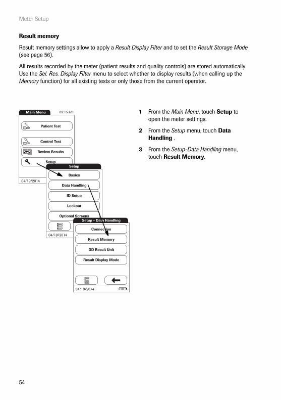
Result memory
Result memory settings allow to apply a Result Display Filter and to set the Result Storage Mode (see page 56).
All results recorded by the meter (patient results and quality controls) are stored automatically. Use the Sel. Res. Display Filter menu to select whether to display results (when calling up the Memory function) for all existing tests or only those from the current operator.
1 From the Main Menu, touch Setup to open the meter settings.
2 From the Setup menu, touch Data Handling .
3 From the Setup-Data Handling menu, touch Result Memory.
Main Menu
Control Test
Review Results
Setup
Patient Test
04/19/2014
09:15 am
Data Handling
ID Setup
Lockout
Basics
Optional Screens
Setup
04/19/2014Result Memory
DD Result Unit
Result Display Mode
Setup - Data Handling
Connection
04/19/2014
Meter Setup
55
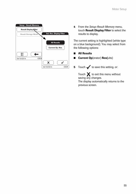
4 From the Setup-Result Memory menu, touch Result Display Filter to select the results to display.
The current setting is highlighted (white type on a blue background). You may select from the following options:
■ All Results
■ Current Op(erator) Res(ults)
5 Touch to save this setting, or:
Touch to exit this menu without saving any changes.The display automatically returns to the previous screen.
Result Storage Mode
Result Display Filter
Setup - Result Memory
04/19/2014
Sel. Res. Display Filter
Current Op. Res.
All Results
04/19/2014
Meter Setup
56
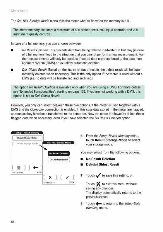
The Sel. Res. Storage Mode menu tells the meter what to do when the memory is full.
In case of a full memory, you can choose between:
■ No Result Deletion. This prevents data from being deleted inadvertently, but may (in case of a full memory) lead to the situation that you cannot perform a new measurement. Fur-ther measurements will only be possible if stored data are transferred to the data man-agement system (DMS) or you allow automatic deletion.
■ Del. Oldest Result. Based on the 1st in/1st out principle, the oldest result will be auto-matically deleted when necessary. This is the only option if the meter is used without a DMS (i.e. no data will be transferred and archived).
However, you only can select between these two options, if the meter is used together with a DMS and the Computer connection is enabled. In this case data stored in the meter are flagged, as soon as they have been transferred to the computer. Now the meter is allowed to delete those flagged data when necessary, even if you have selected the No Result Deletion option.
The meter memory can store a maximum of 500 patient tests, 500 liquid controls, and 200 instrument quality controls.
The option No Result Deletion is available only when you are using a DMS. For more details see “Extended Functionalities”, starting on page 132. If you are not working with a DMS, this option is set to Del. Oldest Result.
6 From the Setup-Result Memory menu, touch Result Storage Mode to select your storage mode.
You may select from the following options:
■ No Result Deletion
■ Del(ete) Oldest Result
7 Touch to save this setting, or:
Touch to exit this menu without saving any changes.The display automatically returns to the previous screen.
8 Touch to return to the Setup-Data Handling menu.
Result Storage Mode
Result Display Filter
Setup - Result Memory
04/19/2014
Sel. Res. Storage Mode
Del. Oldest Result
No Result Deletion
04/19/2014
Meter Setup
57
Result unit
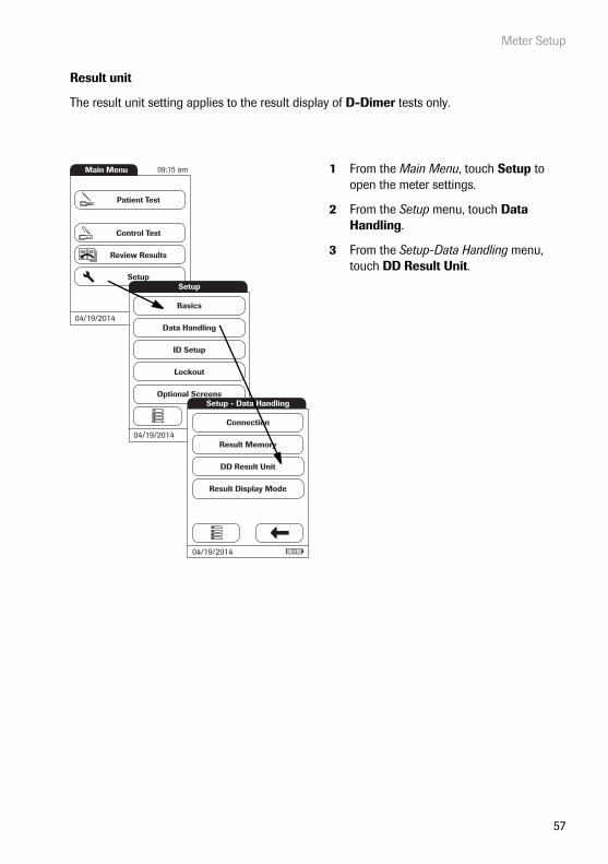
The result unit setting applies to the result display of D-Dimer tests only.
1 From the Main Menu, touch Setup to open the meter settings.
2 From the Setup menu, touch Data Handling.
3 From the Setup-Data Handling menu, touch DD Result Unit.
Main Menu
Control Test
Review Results
Setup
Patient Test
04/19/2014
09:15 am
Data Handling
ID Setup
Lockout
Basics
Optional Screens
Setup
04/19/2014Result Memory
DD Result Unit
Result Display Mode
Setup - Data Handling
Connection
04/19/2014
Meter Setup
58
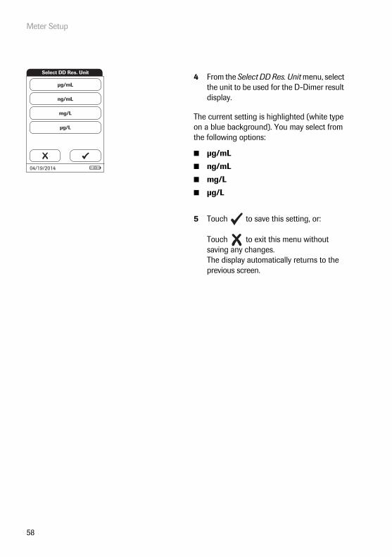
4 From the Select DD Res. Unit menu, select the unit to be used for the D-Dimer result display.
The current setting is highlighted (white type on a blue background). You may select from the following options:
■ μg/mL
■ ng/mL
■ mg/L
■ μg/L
5 Touch to save this setting, or:
Touch to exit this menu without saving any changes.The display automatically returns to the previous screen.
ng/mL
mg/L
µg/L
Select DD Res. Unit
µg/mL
04/19/2014
Meter Setup
59
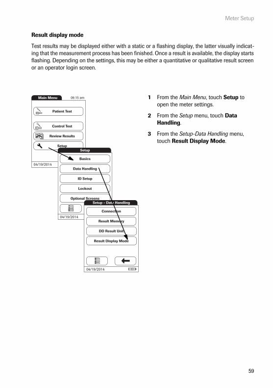
Result display mode
Test results may be displayed either with a static or a flashing display, the latter visually indicat-ing that the measurement process has been finished. Once a result is available, the display starts flashing. Depending on the settings, this may be either a quantitative or qualitative result screen or an operator login screen.
1 From the Main Menu, touch Setup to open the meter settings.
2 From the Setup menu, touch Data Handling.
3 From the Setup-Data Handling menu, touch Result Display Mode.
Main Menu
Control Test
Review Results
Setup
Patient Test
04/19/2014
09:15 am
Data Handling
ID Setup
Lockout
Basics
Optional Screens
Setup
04/19/2014Result Memory
DD Result Unit
Result Display Mode
Setup - Data Handling
Connection
04/19/2014
Meter Setup
60
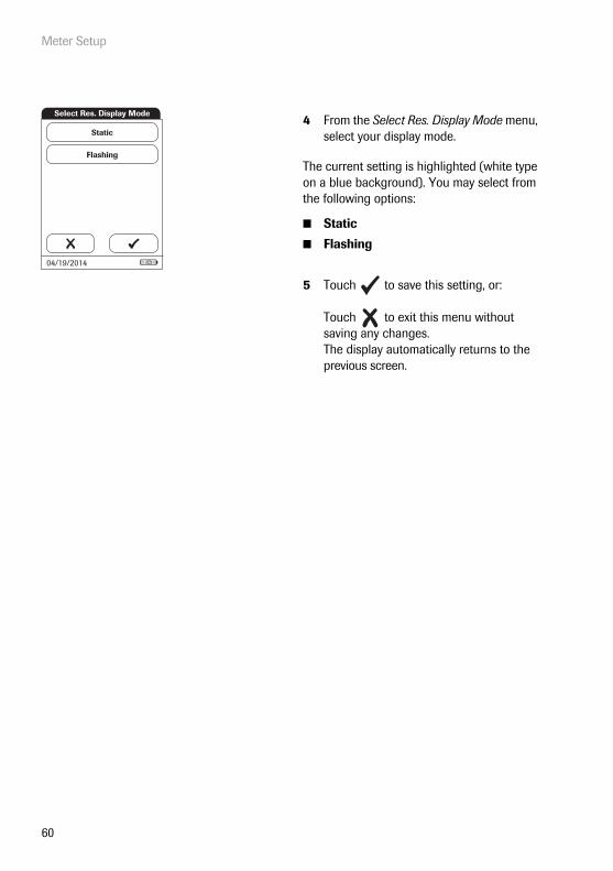
4 From the Select Res. Display Mode menu, select your display mode.
The current setting is highlighted (white type on a blue background). You may select from the following options:
■ Static
■ Flashing
5 Touch to save this setting, or:
Touch to exit this menu without saving any changes.The display automatically returns to the previous screen.
Flashing
Select Res. Display Mode
Static
04/19/2014
Meter Setup
61
5.3 ID Setup setting
Use the ID Setup menu to enter settings for user management and patient management. These settings are optional and set to Off/Inactive by default; the meter can be operated without these settings.
There are three types of identification used with the meter:
■ System Administrator: The administrator has special rights to enter certain meter set-tings and is the only one who can enter and change these settings. It is not necessary for administrator identification to be activated to use the cobas h 232 meter. However, it might be desired or necessary, depending on the regulatory environment and the site of use.
■ Operator: The Operator ID is assigned to persons who use the meter to run tests. If you want to use Operator IDs, you have several options:
– You may use Operator IDs to restrict the use of the meter to qualified personnel or a predefined group of users. In this case an operator list created on a DMS must be trans-ferred to the meter, enabling you to select an Operator ID when logging in. For more details see “Data handling”, starting on page 132.
– You may use Operator IDs for informational purposes only, in order to assign stored measurement results to the users who performed the test. In this case Operator IDs may directly be entered on the meter (by keypad or scanner), with or without an operator list being available.
■ Patient: The Patient ID is assigned to the person, whose test results are recorded. You can either:
– block input of a unique Patient ID (in this case, every test is simply numbered in consecutive order)
– allow a unique Patient ID as optional, or
– require a unique Patient ID for every test. Patient lists created on a DMS can also be trans-ferred to the meter, enabling you to select Patient IDs for a test from these lists. For more details see “Data handling”, starting on page 132.
Operator IDs can be selected from a list (if available) or read by the barcode scanner on the front of the meter. If passwords were created, they must be entered via the onscreen keypad. Patient IDs can be entered by using the onscreen keypad or the barcode scanner on the front of the meter.

Meter Setup
62
Administrator ID
In the default setting, the meter is not protected with an Administrator ID, and all setup options are accessible to every user. If you set up an Administrator ID, the following setup areas are auto-matically reserved only for the administrator (i.e., the person who knows the password):
■ Screen: Date/Time
■ Data Handling
■ ID Setup
■ Quality control and the associated lockouts
■ Optional screens
The setup of an Administrator ID does not limit or alter the usage of the meter for measurements in any way. Furthermore setting up the Administrator ID has no impact on the usage of Operator IDs. Only the setup options as listed above are tied to administrator access.
When you enter an Administrator ID, this ID must be entered from this point forward before any future IDs can be set up (anywhere in the ID Setup menu). The Administrator ID must also be entered before you can delete or change the Administrator ID.
If you forget the Administrator ID, the meter setup may be unlocked via the external data man-agement system (e.g., cobas IT 1000). If you don’t use such a system and need to reset the Administrator ID, contact your Roche representative (see Chapter 12).
Meter Setup
63
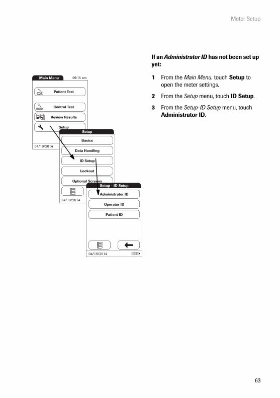
If an Administrator ID has not been set up yet:
1 From the Main Menu, touch Setup to open the meter settings.
2 From the Setup menu, touch ID Setup.
3 From the Setup-ID Setup menu, touch Administrator ID.
Main Menu
Control Test
Review Results
Setup
Patient Test
04/19/2014
09:15 am
Data Handling
ID Setup
Lockout
Basics
Optional Screens
Setup
04/19/2014Operator ID
Patient ID
Administrator ID
Setup - ID Setup
04/19/2014

Meter Setup
64
4 Using the onscreen keypad, enter the Administrator ID of choice (or the pass-word provided by Roche Diagnostics). The ID can consist of up to 20 alpha-numeric characters.
Pay close attention to the buttons you press, because the characters are not displayed on the screen. Asterisks are displayed instead (as if entering a password on a computer).
5 Use to switch to the input of numbers.
6 Use to switch back to the input of text.
7 Use to backspace and correct a mistake.
8 Touch to save this Administrator ID, or:Touch to exit this menu without saving any changes.
A
****|B C D E
F G H I J
K L M N O
P Q R S T
U V W X Y
Z 123
Enter Administrator ID
Enter Administrator ID
0 1 2 3 4
5 6 7 8 9
ABC
****|
123
ABC

Meter Setup
65
9 Enter the Administrator ID again (the onscreen keypad is automatically dis-played again) to confirm the first entry.
Touch to save this entry, (the Administrator ID is now set), or
Touch to exit this menu, the Administrator ID is not set and is therefore still inactive.
The display automatically returns to the Setup-ID Setup menu. After you exit the Setup menu, only an authenticated administrator may set up any further IDs.
Repeat Administrator ID
A
****|B C D E
F G H I J
K L M N O
P Q R S T
U V W X Y
Z 123
Meter Setup
66
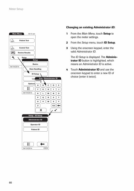
Changing an existing Administrator ID:
1 From the Main Menu, touch Setup to open the meter settings.
2 From the Setup menu, touch ID Setup.
3 Using the onscreen keypad, enter the valid Administrator ID.
The ID Setup is displayed. The Adminis-trator ID button is highlighted, which means an Administrator ID is active.
4 Touch Administrator ID and use the onscreen keypad to enter a new ID of choice (enter it twice).
Main Menu
Control Test
Review Results
Setup
Patient Test
04/19/2014
09:15 am
Data Handling
ID Setup
Lockout
Basics
Optional Screens
Setup
04/19/2014
A
****|B C D E
F G H I J
K L M N O
P Q R S T
U V W X Y
Z 123
Enter Administrator ID
Operator ID
Patient ID
Administrator ID
Setup - ID Setup
04/19/2014

Meter Setup
67
Disabling an existing Administrator ID:
1 From the Main Menu, touch Setup to open the meter settings.
2 From the Setup menu, touch ID Setup.
3 Using the onscreen keypad, enter the valid Administrator ID.
The ID Setup is displayed. The Adminis-trator ID button is highlighted, which means an Administrator ID is active.
4 Touch Administrator ID.
5 Touch to close the onscreen keypad without entering an ID number.
The Administrator ID has been deleted and therefore deactivated. The Adminis-trator ID button is no longer highlighted.
Main Menu
Control Test
Review Results
Setup
Patient Test
04/19/2014
09:15 am
Data Handling
ID Setup
Lockout
Basics
Optional Screens
Setup
04/19/2014
A
****|B C D E
F G H I J
K L M N O
P Q R S T
U V W X Y
Z 123
Enter Administrator ID
Operator ID
Patient ID
Administrator ID
Setup - ID Setup
04/19/2014
A
|B C D E
F G H I J
K L M N O
P Q R S T
U V W X Y
Z 123
Enter Administrator ID
Meter Setup
68
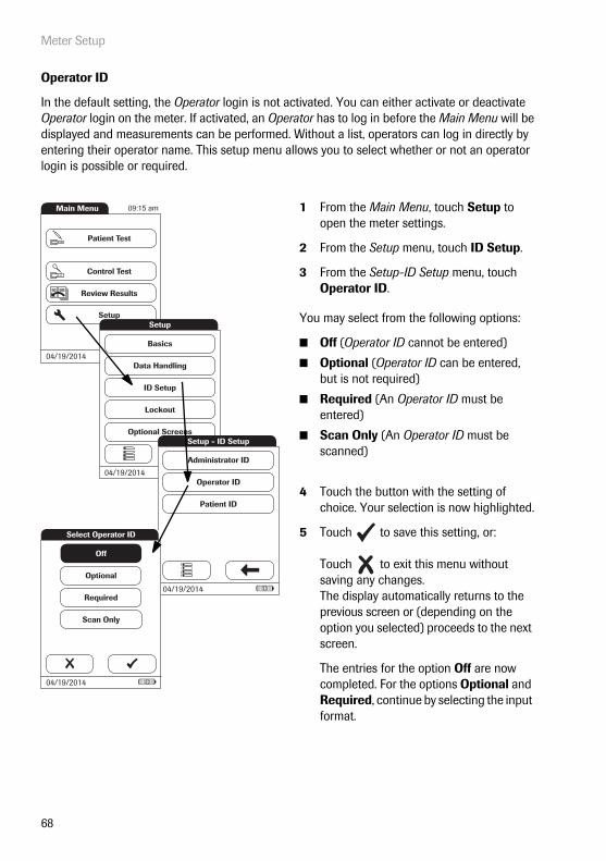
Operator ID
In the default setting, the Operator login is not activated. You can either activate or deactivate Operator login on the meter. If activated, an Operator has to log in before the Main Menu will be displayed and measurements can be performed. Without a list, operators can log in directly by entering their operator name. This setup menu allows you to select whether or not an operator login is possible or required.
1 From the Main Menu, touch Setup to open the meter settings.
2 From the Setup menu, touch ID Setup.
3 From the Setup-ID Setup menu, touch Operator ID.
You may select from the following options:
■ Off (Operator ID cannot be entered)
■ Optional (Operator ID can be entered, but is not required)
■ Required (An Operator ID must be entered)
■ Scan Only (An Operator ID must be scanned)
4 Touch the button with the setting of choice. Your selection is now highlighted.
5 Touch to save this setting, or:
Touch to exit this menu without saving any changes.The display automatically returns to the previous screen or (depending on the option you selected) proceeds to the next screen.
The entries for the option Off are now completed. For the options Optional and Required, continue by selecting the input format.
Main Menu
Control Test
Review Results
Setup
Patient Test
04/19/2014
09:15 am
Data Handling
ID Setup
Lockout
Basics
Optional Screens
Setup
04/19/2014Operator ID
Patient ID
Administrator ID
Setup - ID Setup
04/19/2014
Select Operator ID
Off
Optional
Required
Scan Only
04/19/2014

Meter Setup
69
6 Select the form for input of the Operator ID.
You may select from the following options:
■ Alphanum. (alphanumeric) Enter any combination of letters and numbers, e.g., “J. DOE 3378”
■ Numeric Enter numbers only, e.g., “3387”
■ Max. Length Enter the maximum number of characters (1 … 20) the Operator ID can have.
7 Touch the button with the form of choice for setting up the Operator ID. Your selec-tion is now highlighted.
8 Touch and to set the number of characters (length) of choice.
9 Touch to save this setting, or:
Touch to exit this menu without saving any changes.
The meter automatically returns to the Setup-ID Setup menu.
Operator ID
Alphanum.
Numeric
Max. Length:
20
04/19/2014

Meter Setup
70
With an Operator list being transferred to the meter, the Operator ID options are different from the options in “standalone” mode.
If you want to create a list of Operator IDs from which you can select an operator, additional software (a data management system) and the Handheld Base Unit are required (for more details see “Data handling”, starting on page 132).
1 From the Main Menu, touch Setup to open the meter settings.
2 From the Setup menu, touch ID Setup.
3 From the Setup-ID Setup menu, touch Operator ID.
You may select from the following options:
■ List (Operator ID must be selected from the list or scanned using the barcode scanner)
■ None (Operator ID cannot be entered or selected)
■ Hidden List (Operator ID must be entered using the barcode scanner or the onscreen keypad)
4 Touch the button with the setting of choice. Your selection is now highlighted.
5 Touch to save this setting, or:
Touch to exit this menu without saving any changes.The display automatically returns to the previous screen.
Main Menu
Control Test
Review Results
Setup
Patient Test
04/19/2014
09:15 am
Data Handling
ID Setup
Lockout
Basics
Optional Screens
Setup
04/19/2014Operator ID
Patient ID
Administrator ID
Setup - ID Setup
04/19/2014
Select Operator ID
List
None
Hidden List
04/19/2014

Meter Setup
71
Patient ID
Patient IDs help you to assign stored results to individual patients. In the default setting, input of Patient IDs is set to No. This means that a consecutive number is assigned to each test. However, you can require that a Patient ID must be entered or make it optional.
If you want to create a list of Patient IDs from which you can select a patient for testing, addi-tional software (a data management system) and the Handheld Base Unit are required (see page 132).
1 From the Main Menu, touch Setup to open the meter settings.
2 From the Setup menu, touch ID Setup.
3 From the Setup-ID Setup menu, touch Patient ID.
You may select from the following options:
■ Off (Patient ID cannot be entered)
■ Optional (Patient ID can be entered, but is not required)
■ Required (The operator must enter the Patient ID)
■ Hidden List (Only available when work-ing with a DMS. The list will not be shown. The operator needs to enter the Patient ID manually or via barcode scan.)
4 Touch the button with the setting of choice. Your selection is now highlighted.
5 Touch to save this setting, or:
Touch to exit this menu without saving any changes.The display automatically returns to the previous screen or (depending on the option you selected) proceeds to the next screen.
The entries for the option Off are now completed. For the options Optional and Required, continue by selecting the input format.
Main Menu
Control Test
Review Results
Setup
Patient Test
04/19/2014
09:15 am
Data Handling
ID Setup
Lockout
Basics
Optional Screens
Setup
04/19/2014Operator ID
Patient ID
Administrator ID
Setup - ID Setup
04/19/2014
Off
Optional
Required
Hidden List
Select Patient ID
04/19/2014

Meter Setup
72
6 Select the form for input of the Patient ID before each test.
You may select from the following options:
■ Alphanum. (alphanumeric) Enter any combination of letters and numbers, e.g., “J. DOE 3378”
■ Numeric Enter numbers only, e.g., “3387”
■ Max. Length Enter the maximum number of characters (1 … 20) the Patient ID can have.
7 Touch the button with the form of choice for the Patient ID. Your selection is now highlighted.
8 Touch and to set the number of characters (length) of choice.
9 Touch to save this setting, or:
Touch to exit this menu without saving any changes.
The display automatically returns to the Setup-ID Setup menu.
Alphanum.
Numeric
Max. Length:
20
Patient ID
04/19/2014
Meter Setup
73
5.4 Lockout setup
The Lockout menu contains the options for quality control tests that the operator is required to perform at specified intervals or based on specific triggers. This is a list of the available lockout options:
■ Operator Lockout
■ QC Settings, containing
– New Lot Lockout– QC Lockout– IQC Lockout– Custom Range Trop T
■ Cleaning Lockout
■ STAT Test Config. (overriding a lockout in an emergency situation)
If the quality control test is not performed as required or if the result is outside the target value range, the meter, parameter or test strip lot is locked from further use. Lockouts can also be set up on an operator-specific basis, i.e., each operator must perform the corresponding quality con-trol tests at specified intervals.
A quality control test must be completed successfully before the meter is made available again (either to the operator or in general) for testing.
The option of setting up lockouts for operators is available only when the meter is set up for operator logins (see page 68) and operator lists are stored in the meter.
In case of an emergency, there may not be the time to first complete the required quality control test if a lockout has been triggered and the meter is "locked". For such cases you may set up so-called STAT Tests (STAT = Short TurnAround Time). This option allows to perform a limited number of tests when an operator lockout or QC lockout is in force. However, once the defined number of STAT tests has been performed, further use of the meter is no longer possible (for the affected test parameter or operator), unless the required quality control test is successfully completed.
STAT tests cannot be performed if IQC lockout is in place or a new lot has not (yet) passed a quality control test (New Lot Lockout).

Meter Setup
74
Operator lockout
To perform a test with the meter, the individual steps must be performed properly. Quality control tests can be performed on a regular basis by every operator to ensure these steps are performed properly. By activating the operator lockout, operators are required to perform regular quality control tests.
1 From the Main Menu, touch Setup to open the meter settings.
2 From the Setup menu, touch Lockout.
3 From the Setup-Lockout menu, touch Operator Lockout.If this button appears in gray (inactive), the option Operator ID is deactivated.
Main Menu
Control Test
Review Results
Setup
Patient Test
04/19/2014
09:15 am
Data Handling
ID Setup
Lockout
Basics
Optional Screens
Setup
04/19/2014
QC Settings
Cleaning Lockout
STAT Test Confi g.
Operator Lockout
Setup - Lockout
04/19/2014

Meter Setup
75
4 Select the time interval of choice in which the required quality control tests must be performed.
You may select from the following options:
■ No (deactivated)
■ Daily
■ Weekly
■ Monthly
■ Every 3 or 6 months
■ Yearly
5 Touch and to display the option of choice on the screen. If the arrow is just an outline , this means no other options are available in the direction indi-cated.
6 Touch the button to select the time interval of choice. Your selection is now high-lighted.
7 Touch to save this setting, or:
Touch to exit this menu without saving any changes.
If you selected No, Operator Lockout is deac-tivated.
No
Daily
Weekly
Monthly
Every 3 Months
Select Operator Lockout
04/19/2014
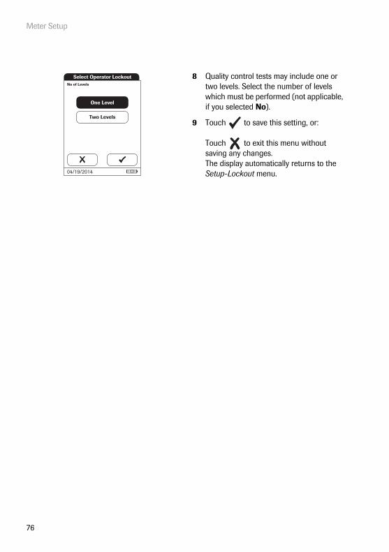
Meter Setup
76
8 Quality control tests may include one or two levels. Select the number of levels which must be performed (not applicable, if you selected No).
9 Touch to save this setting, or:
Touch to exit this menu without saving any changes.The display automatically returns to the Setup-Lockout menu.
Two Levels
One Level
No of Levels
Select Operator Lockout
04/19/2014
Meter Setup
77
Quality control (QC) settings
QC Settings define that operator-independent quality control tests must be run on a regular basis. Lockouts may be triggerd by selectable time periods, and lockouts may be triggered by certain events. The QC Settings menu contains the following options:
■ QC Lockout (time-based), with the additional option of a New Lot Lockout (applies every time a new test strip lot is used)
■ IQC Lockout (time-based)
■ Custom Range Trop. T (customize the QC Range in accordance with applicable local guidelines)
■ QC Result Format (select the format for QC result displays)
■ Reset Test Param. (reset all test parameters, including code chip data and QC lockouts)

Meter Setup
78
1 From the Main Menu, touch Setup to open the meter settings.
2 From the Setup menu, touch Lockout.
3 From the Setup-Lockout menu, touch QC Settings.
Main Menu
Control Test
Review Results
Setup
Patient Test
04/19/2014
09:15 am
Data Handling
ID Setup
Lockout
Basics
Optional Screens
Setup
04/19/2014
QC Settings
Cleaning Lockout
STAT Test Confi g.
Operator Lockout
Setup - Lockout
04/19/2014
QC Lockout
IQC Lockout
QC Result Format
Custom Range Trop. T
Reset Test Param.
Setup - QC Settings
04/19/2014

Meter Setup
79
Quality control (QC) lockout
A QC Lockout requires a quality control test to be performed. You may also set the number of levels for this test. You may select from the following options:
■ New Lot: Yes/No (applies every time a new test strip lot is used)
The general intervals are:
■ No
■ Daily
■ Weekly
■ Monthly
All enabled QC Lockouts, if the time period has elapsed, are activated at 8:00 a.m. (default set-ting, time can be changed with a DMS).
See page 78 on how to access the Setup-QC Settings menu.
1 Touch QC Lockout to set regularly recur-ring quality control tests for available test parameters.
2 New Lot: Touch Yes if you want to force a control test every time a new test strip lot is used. Otherwise touch No.
3 Time intervals: Touch the button to select the time interval of choice (e.g., Daily). Your selection is now highlighted.
4 Touch to save this setting, or:
Touch to exit this menu without saving any changes.
5 Quality control tests may include one or two levels. Select the number of levels which must be performed (not applicable, if you selected No).
6 Touch to save this setting, or:
Touch to exit this menu without saving any changes.The display automatically returns to the previous screen.
QC Lockout
IQC Lockout
QC Result Format
Custom Range Trop. T
Reset Test Param.
Setup - QC Settings
04/19/2014
Setup - LockoutNew Lot:
Yes No
Daily
Weekly
Monthly
No
09:15 am
04/19/2014

Meter Setup
80
Instrument quality control (IQC) lockout
An IQC Lockout also requires a quality control test with dedicated IQC test strips to be per-formed. You may select from the following options:
■ No
■ Daily
■ Weekly
■ Monthly
All enabled IQC Lockouts, if the time period has elapsed, are activated at 8:00 a.m. (default set-ting, time can be changed with a DMS).
See page 78 on how to access the Setup-QC Settings menu.
1 Touch IQC Lockout to set regularly recur-ring instrument quality control tests (IQC = Instrument Quality Control).
2 Touch the button to select the time interval of choice. Your selection is now high-lighted.
3 Touch to save this setting, or:
Touch to exit this menu without saving any changes.The display automatically returns to the previous screen.
QC Lockout
IQC Lockout
QC Result Format
Custom Range Trop. T
Reset Test Param.
Setup - QC Settings
04/19/2014
No
Daily
Weekly
Monthly
Select IQC Lockout
04/19/2014

Meter Setup
81
QC result format
The QC Result format defines the kind of information that is displayed in a QC result screen. You may select from the following options:
■ Display without a value, but with text “Pass” or “Fail”
■ Display a value
■ Display as value and with text “Pass” or “Fail”
See page 78 on how to access the Setup-QC Settings menu.
1 Touch QC Result Format to set the dis-play format.
2 Touch the button to select the result format of choice. Your selection is now highlighted.
3 Touch to save this setting, or:
Touch to exit this menu without saving any changes.The display automatically returns to the previous screen.
QC Lockout
IQC Lockout
QC Result Format
Custom Range Trop. T
Reset Test Param.
Setup - QC Settings
04/19/2014
Pass/Fail
Value
Value & Pass/Fail
Select QC Result Format
04/19/2014
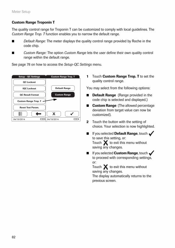
Meter Setup
82
Custom Range Troponin T
The quality control range for Troponin T can be customized to comply with local guidelines. The Custom Range Trop. T function enables you to narrow the default range.
■ Default Range: The meter displays the quality control range provided by Roche in the code chip.
■ Custom Range: The option Custom Range lets the user define their own quality control range within the default range.
See page 78 on how to access the Setup-QC Settings menu.
1 Touch Custom Range Trop. T to set the quality control range.
You may select from the following options:
■ Default Range (Range provided in the code chip is selected and displayed.)
■ Custom Range (The allowed percentage deviation from target value can now be customized).
2 Touch the button with the setting of choice. Your selection is now highlighted.
■ If you selected Default Range, touch to save this setting, or:Touch to exit this menu without saving any changes.
■ If you selected Custom Range, touch to proceed with corresponding settings, or:Touch to exit this menu without saving any changes.The display automatically returns to the previous screen.
QC Lockout
IQC Lockout
QC Result Format
Custom Range Trop. T
Reset Test Param.
Setup - QC Settings
04/19/2014
Custom Range
Default Range
Custom Range Trop. T
04/19/2014

Meter Setup
83
If you selected Custom Range, the Custom Range screen opens and offers you the option of customizing the deviation from target value (percentage value).
For the control solutions, the target value always comes from the information stored in the code chip. If you have chosen Custom Range, you can now select an allowed devia-tion from target value in the range of 0 to 50% (in the illustration, 21%).
3 Use the arrows to to set the allowed per-centage deviation from the target value.
■ Touch to save this setting, or:
Touch to exit this menu without saving any changes.The display automatically returns to the previous screen.
Custom Range
Default Range
Custom Range Trop. T
04/19/2014
Custom Range Trop. T
Deviation from target value (in %):
21
04/19/2014
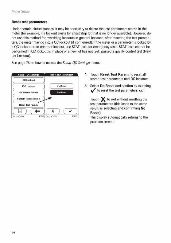
Meter Setup
84
Reset test parameters
Under certain circumstances, it may be necessary to delete the test parameters stored in the meter (for example, if a lockout exists for a test strip lot that is no longer available). However, do not use this method for overriding lockouts in general because, after resetting the test parame-ters, the meter may go into a QC lockout (if configured). If the meter or a parameter is locked by a QC lockout or an operator lockout, use STAT tests for emergency tests. STAT tests cannot be performed if IQC lockout is in place or a new lot has not (yet) passed a quality control test (New Lot Lockout).
See page 78 on how to access the Setup-QC Settings menu.
4 Touch Reset Test Param. to reset all stored test parameters and QC lockouts.
5 Select Do Reset and confirm by touching to reset the test parameters, or:
Touch to exit without resetting the test parameters (this leads to the same result as selecting and confirming No Reset). The display automatically returns to the previous screen.
QC Lockout
IQC Lockout
QC Result Format
Custom Range Trop. T
Reset Test Param.
Setup - QC Settings
04/19/2014
No Reset
Do Reset
Reset Test Parameter
04/19/2014

Meter Setup
85
Cleaning lockout
Under normal handling conditions, your meter will not be exposed to significant dirt or contami-nation. However, circumstances might require regular checks of the test strip guide and (when necessary) cleaning of the meter. The Cleaning Lockout allows operators to specify time intervals for cleaning.
1 From the Main Menu, touch Setup to open the meter settings.
2 From the Setup menu, touch Lockout.
3 From the Setup-Lockout menu, touch Cleaning Lockout.
You may select from the following options:
■ No
■ Daily
■ Weekly
■ Monthly
4 Touch the button to select the time interval of choice. Your selection is now high-lighted.
5 Touch to save this setting, or:
Touch to exit this menu without saving any changes.The display automatically returns to the previous screen.
Main Menu
Control Test
Review Results
Setup
Patient Test
04/19/2014
09:15 am
Data Handling
ID Setup
Lockout
Basics
Optional Screens
Setup
04/19/2014
QC Settings
Cleaning Lockout
STAT Test Confi g.
Operator Lockout
Setup - Lockout
04/19/2014
Daily
Weekly
Monthly
No
Select Cleaning Lockout
04/19/2014

Meter Setup
86
STAT test configuration
Quality control tests ensure consistent quality and accurate measurements. In emergency situa-tions, however, it may be necessary to perform a test without delay. To override an active lockout for a test parameter, lot or operator, you can allow for STAT Tests (STAT = Short TurnAround Time). STAT tests cannot be performed if IQC lockout is in place or a new lot has not (yet) passed a quality control test (New Lot Lockout).
You can set a number of tests permitted beyond the lockout. Once the number of allowed STAT Tests has been reached (for a single parameter), additional tests for this parameter are locked until you successfully perform a quality control test.
STAT tests are labelled accordingly in the result window.
STAT Tests will be counted separately for each test parameter. Thus the actual availability of STAT Tests may differ for each parameter.
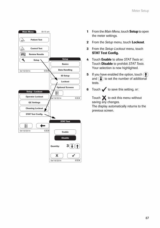
Meter Setup
87
1 From the Main Menu, touch Setup to open the meter settings.
2 From the Setup menu, touch Lockout.
3 From the Setup-Lockout menu, touch STAT Test Config.
4 Touch Enable to allow STAT Tests or:Touch Disable to prohibit STAT Tests.Your selection is now highlighted.
5 If you have enabled the option, touch and to set the number of additional tests.
6 Touch to save this setting, or:
Touch to exit this menu without saving any changes.The display automatically returns to the previous screen.
Main Menu
Control Test
Review Results
Setup
Patient Test
04/19/2014
09:15 am
Data Handling
ID Setup
Lockout
Basics
Optional Screens
Setup
04/19/2014
QC Settings
Cleaning Lockout
STAT Test Confi g.
Operator Lockout
Setup - Lockout
04/19/2014
Disable
Enable
Quantity: 3
STAT Test
04/19/2014

Meter Setup
88
5.5 Optional Screens setup
In this screen, you can customise display formats and test procedures. You can choose to display additional information and select from options for managing the result display.
1 From the Main Menu, touch Setup to open the meter settings.
2 From the Setup menu, touch Optional Screens.
In this menu screen, you may select from the following options:
■ Display additional information on meter status
■ Select to display results only after new login by operator
■ Enable operators to confirm or reject test results
Main Menu
Control Test
Review Results
Setup
Patient Test
04/19/2014
09:15 am
Data Handling
ID Setup
Lockout
Basics
Optional Screens
Setup
04/19/2014
Setup - Optional Screens
Result Login
Result Confi rmation
Start Info
04/19/2014

Meter Setup
89
The additional status information is displayed after powering on the meter or after logging off as an operator. This includes information about current lockouts, the number of results not trans-ferred (to the DMS) and the time since the last data transfer.
In environments with multiple operators, it can be useful to display a test only if the operator carrying out the test is present. By requiring operators to login again before displaying results, you ensure that only authorised persons view the results.
3 Touch Start Info.
4 Touch the button to select the state of the status display. Your selection is now high-lighted.
5 Touch to save this setting, or:
Touch to exit this menu without saving any changes.
6 Touch Result Login.
7 Touch the button to select the state of the option. Your selection is now highlighted.
8 Touch to save this setting, or:
Touch to exit this menu without saving any changes.
Setup - Optional Screens
Result Login
Result Confi rmation
Start Info
04/19/2014
Disable
Enable
Start Info Screen
04/19/2014
Setup - Optional Screens
Result Login
Result Confi rmation
Start Info
04/19/2014
Disable
Enable
Result Login Screen
04/19/2014

Meter Setup
90
In some circumstances, it may be useful for operators to confirm the validity of their results. To do so, an option can be enabled that prompts operators to confirm the results of every test.
9 Touch Result Confirmation.
10 Touch the button to select the state of the option. Your selection is now highlighted.
11 Touch to save this setting, or:
Touch to exit this menu without saving any changes.
Setup - Optional Screens
Result Login
Result Confi rmation
Start Info
04/19/2014
Disable
Enable
Res. Confi rmation Screen
04/19/2014
Performing a Test
91
6 Performing a Test
What you need:
■ Suitable blood sampling system to collect venous whole blood
■ cobas h 232 meter
■ Roche CARDIAC test strips for the desired test, with the supplied code chip
■ Roche CARDIAC pipettes (or other suitable pipettes with pipetting volume of 150 μL) for applying the sample to the test strip
Always …
■ … operate the meter according to the specified operating conditions (see page 147).
■ … follow the information on correct handling of test strips in the package insert.
■ … place the meter on a level, vibration-free surface when applying the sample to the sample application area of the test strip. Once the sample has been completely absorbed by the test strip, you can move the meter.
■ … keep the meter clean. See “Cleaning and Disinfecting the Meter” on page 139.
Only heparinized blood collection tubes are allowed. Refer to test strip package insert.
The Roche CARDIAC family includes several strips. Always ensure that the disposables you are using (e.g., test strips) are intended for use with the cobas h 232 meter. Some tests might require a minimum software version. Ensure that the software version on the cobas h 232 meter is compatible with the test you are running (refer to the corresponding package insert for details). Contact your Roche representative if the cobas h 232 meter requires a software update.

Performing a Test
92
Never …
■ … use Roche CARDIAC pipettes for collecting blood from the patient.
■ … touch or remove the test strip during a test.
■ … add more blood after the test has begun.
■ … remove or insert the code chip while the meter is performing a test.
■ … move or pick up the meter while applying the sample - wait until the necessary sample has been absorbed completely by the test strip.
■ … store the meter at extreme temperatures.
■ … store the meter in damp or humid conditions without protection.
Sample material
Heparinized venous whole blood is used as sample material. For each test use exactly 150 μL of sample.
Use a suitable sampling system to collect the blood sample. Use only heparinized blood collec-tion tubes. Do not use blood collection tubes containing EDTA, citrate, sodium fluoride or other additives. For details refer to the test strip package insert.
CAUTION
Accuracy/precision of measured results: Failure to comply with the above may lead to inaccurate results. An incorrect result may lead to an error in diagnosis, therefore posing danger to the patient.
IMPORTANT NOTE: Do not use Roche CARDIAC pipettes for blood sampling from the vein or for injections. Roche CARDIAC pipettes are intended only for drawing the sample from the blood collection tube and applying it to the test strip. See page 106.
■ Observe the applicable regulations and directives for hygiene and safety when collecting blood samples.
■ Observe the applicable regulations and directives for disposing of potentially infectious samples and materials.
■ Dispose of used consumables in line with the disposal policy of your hospital, institute or medical practice.
■ See safety message “Protection against infection and blood-borne pathogens” on page 12.
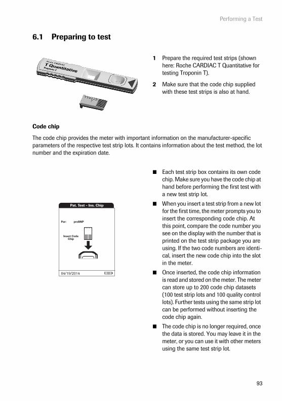
Performing a Test
93
6.1 Preparing to test
Code chip
The code chip provides the meter with important information on the manufacturer-specific parameters of the respective test strip lots. It contains information about the test method, the lot number and the expiration date.
1 Prepare the required test strips (shown here: Roche CARDIAC T Quantitative for testing Troponin T).
2 Make sure that the code chip supplied with these test strips is also at hand.
■ Each test strip box contains its own code chip. Make sure you have the code chip at hand before performing the first test with a new test strip lot.
■ When you insert a test strip from a new lot for the first time, the meter prompts you to insert the corresponding code chip. At this point, compare the code number you see on the display with the number that is printed on the test strip package you are using. If the two code numbers are identi-cal, insert the new code chip into the slot in the meter.
■ Once inserted, the code chip information is read and stored on the meter. The meter can store up to 200 code chip datasets (100 test strip lots and 100 quality control lots). Further tests using the same strip lot can be performed without inserting the code chip again.
■ The code chip is no longer required, once the data is stored. You may leave it in the meter, or you can use it with other meters using the same test strip lot.
Pat. Test - Ins. Chip
Insert Code Chip
proBNPPar:
04/19/2014
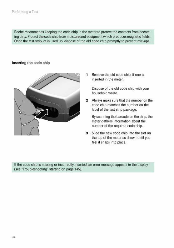
Performing a Test
94
Inserting the code chip
Roche recommends keeping the code chip in the meter to protect the contacts from becom-ing dirty. Protect the code chip from moisture and equipment which produces magnetic fields. Once the test strip lot is used up, dispose of the old code chip promptly to prevent mix-ups.
1 Remove the old code chip, if one is inserted in the meter.
Dispose of the old code chip with your household waste.
2 Always make sure that the number on the code chip matches the number on the label of the test strip package.
By scanning the barcode on the strip, the meter gathers information about the number of the required code chip.
3 Slide the new code chip into the slot on the top of the meter as shown until you feel it snaps into place.
If the code chip is missing or incorrectly inserted, an error message appears in the display (see “Troubleshooting” starting on page 145).
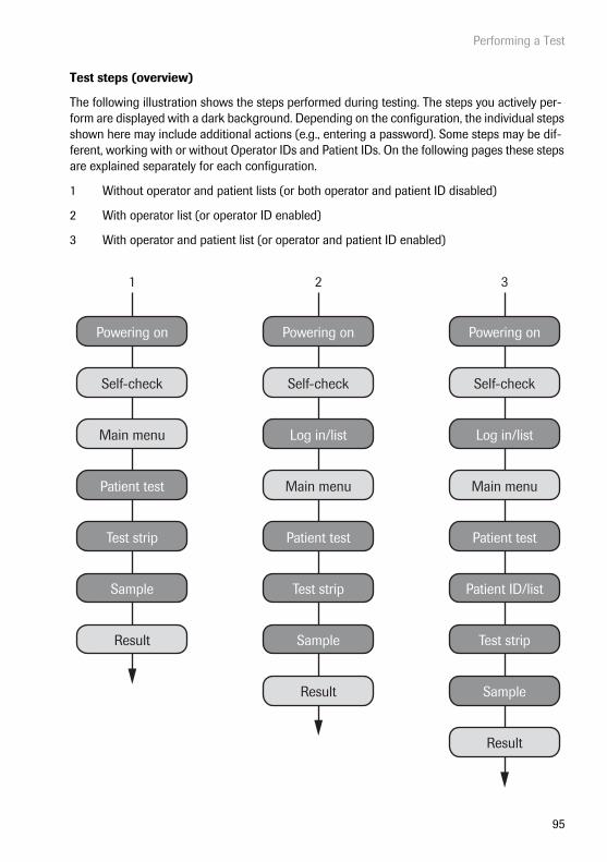
Performing a Test
95
Test steps (overview)
The following illustration shows the steps performed during testing. The steps you actively per-form are displayed with a dark background. Depending on the configuration, the individual steps shown here may include additional actions (e.g., entering a password). Some steps may be dif-ferent, working with or without Operator IDs and Patient IDs. On the following pages these steps are explained separately for each configuration.
1 Without operator and patient lists (or both operator and patient ID disabled)
2 With operator list (or operator ID enabled)
3 With operator and patient list (or operator and patient ID enabled)
Powering on
Self-check
Main menu
Patient test
Test strip
Sample
Result
Powering on
Self-check
Main menu
Log in/list
Patient test
Test strip
Sample
Result
Powering on
1 2 3
Self-check
Main menu
Log in/list
Patient test
Patient ID/list
Test strip
Sample
Result

Performing a Test
96
Powering on the meter
1 Power the meter on by pressing the button for approximately 1 second.
You can also power on the meter directly by connecting the handheld power supply.
The meter performs a self-check at startup.
Self-Check
Performing self-checks...
SW Version: 03.00.00
04/19/2014
09:15 am
Self-Check
Self-checks complete.
09:15 am
04/19/2014

Performing a Test
97
Logging in
The initial steps until the Main Menu is displayed depend on the configuration and are performed as follows:
Without operator login required
With operator login (no operator list)
2 Wait until the main menu is displayed.
2 Enter or scan your Operator ID.
3 Touch to confirm your entry.
4 Wait until the main menu is displayed.
Main Menu
Control Test
Review Results
Setup
Patient Test
04/19/2014
09:15 am
A
SC123B C D E
F G H I J
K L M N O
P Q R S T
U V W X Y
Z , 123
Operator ID
Scan
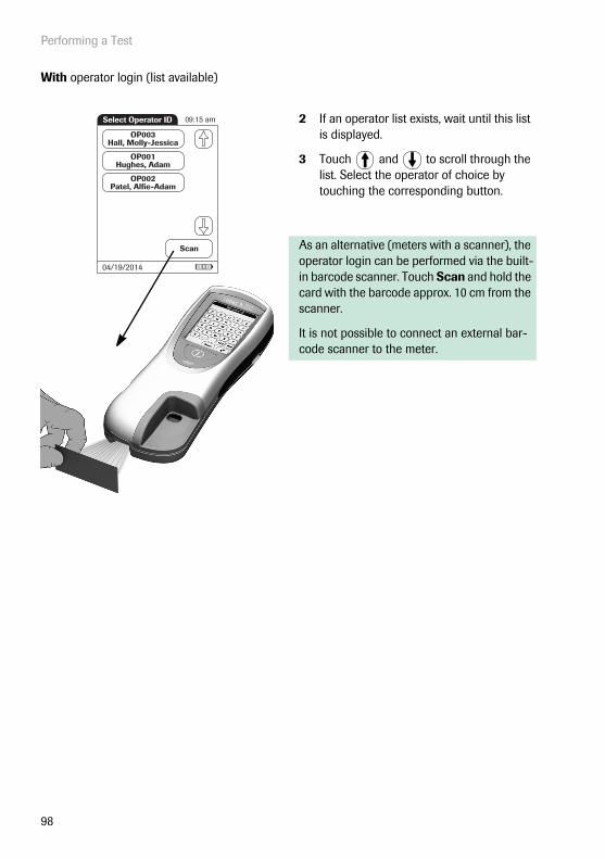
Performing a Test
98
With operator login (list available)
2 If an operator list exists, wait until this list is displayed.
3 Touch and to scroll through the list. Select the operator of choice by touching the corresponding button.
As an alternative (meters with a scanner), the operator login can be performed via the built-in barcode scanner. Touch Scan and hold the card with the barcode approx. 10 cm from the scanner.
It is not possible to connect an external bar-code scanner to the meter.
OP003Hall, Molly-Jessica
OP001Hughes, Adam
OP002Patel, Alfi e-Adam
Select Operator ID
Scan
04/19/2014
09:15 am
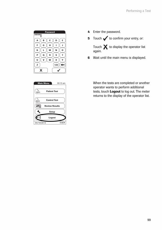
Performing a Test
99
4 Enter the password.
5 Touch to confirm your entry, or:
Touch to display the operator list again.
6 Wait until the main menu is displayed.
When the tests are completed or another operator wants to perform additional tests, touch Logout to log out. The meter returns to the display of the operator list.
A B C D E
F G H I J
K L M N O
P Q R S T
U V W X Y
Z 123
Password
****|
Main Menu
Control Test
Review Results
Setup
Patient Test
Logout
09:15 am
04/19/2014
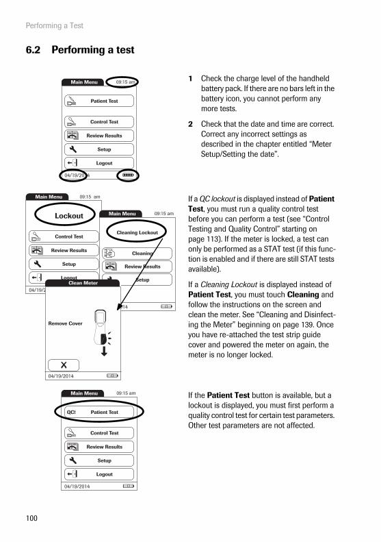
Performing a Test
100
6.2 Performing a test
1 Check the charge level of the handheld battery pack. If there are no bars left in the battery icon, you cannot perform any more tests.
2 Check that the date and time are correct. Correct any incorrect settings as described in the chapter entitled “Meter Setup/Setting the date”.
If a QC lockout is displayed instead of Patient Test, you must run a quality control test before you can perform a test (see “Control Testing and Quality Control” starting on page 113). If the meter is locked, a test can only be performed as a STAT test (if this func-tion is enabled and if there are still STAT tests available).
If a Cleaning Lockout is displayed instead of Patient Test, you must touch Cleaning and follow the instructions on the screen and clean the meter. See “Cleaning and Disinfect-ing the Meter” beginning on page 139. Once you have re-attached the test strip guide cover and powered the meter on again, the meter is no longer locked.
If the Patient Test button is available, but a lockout is displayed, you must first perform a quality control test for certain test parameters. Other test parameters are not affected.
Main Menu
Control Test
Review Results
Setup
Patient Test
Logout
09:15 am
04/19/2014
Main Menu
Control Test
Review Results
Setup
Lockout
Logout
09:15 am
04/19/2014
Main Menu
Cleaning Lockout
Cleaning
Review Results
Setup
09:15 am
04/19/2014
Clean Meter
Remove Cover
04/19/2014
Main Menu
Control Test
Review Results
Setup
Patient Test
Logout
QC!
09:15 am
04/19/2014

Performing a Test
101
Without patient list
3 Touch Patient Test.
4 If you selected the Patient ID as optional, you can enter or scan a Patient ID.If you selected the Patient ID as required, you must enter or scan the Patient ID.If you selected no Patient ID (None), the meter automatically proceeds to the next step.
5 Touch to confirm the ID, or:
Touch to cancel the ID entry.
Continue reading on page 104.
A
PID111SCHULZM457
B C D E
F G H I J
K L M N O
P Q R S T
U V W X Y
Z , 123
Patient ID
Scan
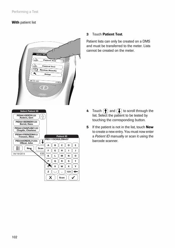
Performing a Test
102
With patient list
3 Touch Patient Test.
Patient lists can only be created on a DMS and must be transferred to the meter. Lists cannot be created on the meter.
4 Touch and to scroll through the list. Select the patient to be tested by touching the corresponding button.
5 If the patient is not in the list, touch New to create a new entry. You must now enter a Patient ID manually or scan it using the barcode scanner.
Select Patient ID
New
PID001GERTA123Anders, Gert
PID001CHAPLINC123Chaplin, Charlene
PID001BERNDH123Bernd, Hans
PID001FRENZENA12Frenzen, Alice
PID230ONEALJ1234ONeal, John
Scan
04/19/2014
A
PID111SCHULZM457
B C D E
F G H I J
K L M N O
P Q R S T
U V W X Y
Z , 123
Patient ID
Scan
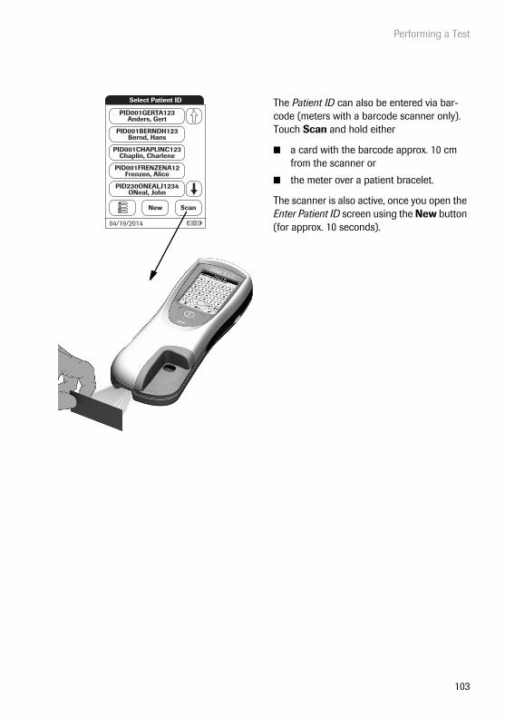
Performing a Test
103
The Patient ID can also be entered via bar-code (meters with a barcode scanner only). Touch Scan and hold either
■ a card with the barcode approx. 10 cm from the scanner or
■ the meter over a patient bracelet.
The scanner is also active, once you open the Enter Patient ID screen using the New button (for approx. 10 seconds).
Select Patient ID
New
PID001GERTA123Anders, Gert
PID001CHAPLINC123Chaplin, Charlene
PID001BERNDH123Bernd, Hans
PID001FRENZENA12Frenzen, Alice
PID230ONEALJ1234ONeal, John
Scan
04/19/2014

Performing a Test
104
Inserting a test strip
1 The test strip icon prompts you to insert a test strip. Remove the test strip from its foil pouch.
2 Hold the test strip so that the application and test area is facing up.
3 Hold the test strip straight and flat. Insert it in the test strip guide of the meter. It is important that you insert the test strip using one smooth movement.
Inserting the test strip too slowly or too fast can cause a barcode reading error.
Slide the test strip in as far as it will go. A beep tone indicates that the meter has detected the test strip (provided the beeper is enabled).
Exposure to external influences (e.g., humidity) may deteriorate the test strips and may lead to error messages! Remove the test strip from its foil pouch only when you are ready to per-form a test.
Pat. Test - Ins. Strip
Insert Strip
JONES, TOMOp:
PID111SCHULZM457SCHULZ, MANFRED
Pat:
04/19/2014

Performing a Test
105
If you use a new test strip lot, you must insert the corresponding code chip once. See “Code chip” on page 93.
Depending on the meter setting, you may also be required to run a quality control test at this point.
The meter identifies the required code chip based on the test strip barcode and displays the code number.
For each test parameter and each new test strip lot a different code key number is displayed.
The thermometer icon shows that the test strip is warming up. A beep tone indicates when the warming-up process is complete (provided the beeper is enabled).
The pipette icon indicates that the meter is ready to perform the test and is waiting for blood to be applied.
Simultaneously, a 5-minute countdown begins. You must apply the sample within this time. Otherwise you will receive an error message (after the sample detection has timed out).
In case of errors, see “Troubleshooting” on page 145.
Pat. Test - Ins. Chip
Insert Code Chip
proBNPPar:
04/19/2014
Pat. Test - Warming Up
Please Wait
Warming Up
PID111SCHULZM457SCHULZ, MANFREDJONES, TOM
Pat:
Op:proBNPPar: PB1234Code:
04/19/2014
Pat. Test - App. Sample
Apply Sample
4:10
PID111SCHULZM457SCHULZ, MANFREDJONES, TOM
Pat:
Op:proBNPPar:
Min
150µL
PB1234Code:
04/19/2014

Performing a Test
106
4 Using the Roche CARDIAC pipette, draw exactly 150 μL (to the blue mark on the pipette) heparinized blood from the blood collection tube. Make sure the sample contains no air bubbles.
5 Apply the entire sample to the sample application area of the test strip.
Always place the meter on a level, vibration-free surface when applying the sample to the sample application area of the test strip. Once the sample has been completely absorbed by the test strip, you can move the meter.
6 Touch to confirm that the sample has been applied.
The hourglass icon appears as the meter begins to process the sample. For better control over the measurement process, you should always confirm this yourself, instead of waiting for the meter to detect the sample.
After you confirm that the sample has been applied, or if the meter automatically recog-nises that the sample has been applied, the
button disappears.
15
0 µ
L

Performing a Test
107
The hourglass icon spins until the sample has been detected and the test begins. The time remaining for the test is displayed.
Measurement time: The time needed to run a test depends on the test parameter (refer to package insert for details). Typically, 8 to 12 minutes are required.
Do not add more blood. Do not touch the test strip until the result is displayed.
For Troponin T only: As soon as the meter detects a signal (this may take a few minutes), a qualitative result (TnT Elevated) appears under the hourglass icon (see illustration).
The quantitative result is displayed when the test is completed. Refer to the Roche CARDIAC T Quantitative package insert for more details.
Pat. Test - Measuring
proBNP PB1234JONES, TOM
Par:Op:
Code:
SCHULZ, MANFREDPat:
10:20 Min
04/19/2014
Pat. Test - Measuring
Trop T TT 2721JONES, TOM
Par:Op:
Code:
SCHULZ, MANFREDPat:
10:20 MinTnT Elevated
04/19/2014

Performing a Test
108
The test result is shown and stored automati-cally.
When interpreting your result, please read the test strip package insert carefully.
Print button: Print results (infrared interface)
Menu button: Return to main menu
Comment button: Add predefined or custom comments to the test result
7 Remove the test strip from the meter.
8 Power the meter off by pressing the button for approximately 1 second.
9 Discard the used disposable item and test strip in compliance with the disposal policy of your hospital or medical practice.
10 Clean the meter if necessary. See “Clean-ing and Disinfecting the Meter” on page 139).
Pat. Test - Result
62001/25/2014 10:17
pg/ml
proBNP PB1234
SCHULZ, MANFREDJONES, TOM
Par:Op:
Code:
PID111SCHULZM457Pat:
04/19/2014

Performing a Test
109
Displaying, confirming or adding comments to results
As described in the chapter “Optional Screens setup” starting on page 88, there are many options for displaying results that can be activated:
If a new Operator Login is required to display the result:
1 Touch the button for Operator Login.
2 Log in as described on page 98.
The result is now displayed.
Pat. Test - Op. Login
Measurement Complete
proBNP PB1234
SCHULZ, MANFREDJONES, TOM
Par:Op:
Code:
PID111SCHULZM457Pat:
04/19/2014

Performing a Test
110
If the test result requires a confirmation:
■ When the result is displayed, touch the button to select the confirmation of choice.
You can choose to either
■ Reject
■ Accept
If you reject the result, the result value is no longer displayed. However, the test entry is stored.
Pat. Test - Confi rm.
62001/25/2014 10:17
pg/ml
proBNP PB1234
SCHULZ, MANFREDJONES, TOM
Par:Op:
Code:
PID111SCHULZM457Pat:
Measurement OK?
Reject Accept
04/19/2014
Pat. Test - Result
Rejected01/25/2014 10:17
proBNP PB1234
SCHULZ, MANFREDJONES, TOM
Par:Op:
Code:
PID111SCHULZM457Pat:
04/19/2014

Performing a Test
111
You can add up to three comments to a test result. Comments can provide, for example, addi-tional information about the test conditions or the patient. A comment may be up to 20 charac-ters in length. You can open the function for adding comments directly in the results screen.
If you want to add a comment, do not remove the test strip. Once the strip is removed, the meter automatically returns to Main Menu and a comment can no longer be added.
If you want to add a comment to a test result:
1 In the result screen, touch .
2 Select a predefined comment from the list and/or
3 Touch Custom to enter your own com-ment using the onscreen keypad.
The comments are stored with the test result.
Pat. Test - Result
62001/25/2014 10:17
pg/ml
proBNP PB1234
SCHULZ, MANFREDJONES, TOM
Par:Op:
Code:
PID111SCHULZM457Pat:
04/19/2014
Pat. Test - Comment
Asymptomatic
Chest Pain
Dyspnea
Symptomatic
Custom
04/19/2014
Pat. Test - Result
62001/25/2014 10:17
pg/ml
Trop T TT 2721User1
Par:Op:
Code:
TESTERPat:
Test
Symptomatic
Chest Pain
04/19/2014
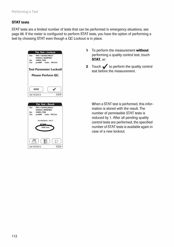
Performing a Test
112
STAT tests
STAT tests are a limited number of tests that can be performed in emergency situations, see page 86. If the meter is configured to perform STAT tests, you have the option of performing a test by choosing STAT even though a QC Lockout is in place.
1 To perform the measurement without performing a quality control test, touch STAT, or:
2 Touch to perform the quality control test before the measurement.
When a STAT test is performed, this infor-mation is stored with the result. The number of permissible STAT tests is reduced by 1. After all pending quality control tests are performed, the specified number of STAT tests is available again in case of a new lockout.
Pat. Test - Lockout
Test Parameter Locked!
Please Perform QC.
PID111SCHULZM457SCHULZ, MANFREDJONES, TOM
Pat:
Op:proBNPPar:
STAT
PB1234Code:
04/19/2014
Pat. Test - Result
62001/25/2014 10:17
pg/ml
proBNP PB1234
SCHULZ, MANFREDJONES, TOM
Par:Op:
Code:
PID111SCHULZM457Pat:
STAT Test
04/19/2014
Control Testing and Quality Control
113
7 Control Testing and Quality Control
The cobas h 232 POC system employs several methods to check that the meter and test strips are working properly and that the operator is performing the test correctly.
The meter has a number of built-in quality control functions:
■ A self-check of the electronic components and functions every time the meter is powered on.
■ A check of test temperature when warming up and during the test.
■ A check of the expiration date and lot information on the test strip using the information from the code chip.
In addition, the cobas h 232 POC system provides:
■ Configurable, prescribed quality control tests using Roche CARDIAC IQC test strips for internal functionality tests.
■ Definable, prescribed control tests using Roche CARDIAC Control materials for the avail-able test parameters.
7.1 Preparing to run a quality control test
Prepare for a quality control test in the same way you would prepare to perform a test with a patient sample. The only difference is the use of control solution instead of blood.
To perform a quality control test using control solutions, you need:
■ cobas h 232 meter
■ Test strips for the desired tests, with the supplied code chip
■ Roche CARDIAC pipettes (or other suitable pipettes with pipetting volume of 150 μL)
■ Control set containing two vials of Roche CARDIAC Control material and code chip

Control Testing and Quality Control
114
You can specify the frequency of quality control tests according to your own requirements (see “Meter Setup/Lockout setup” starting on page 73).
If you encounter a lockout for a test strip lot that no longer exists, see “Reset test parameters” on page 84. Please note that, when you use this method, all saved test parameters and QC lockouts will be deleted.
Always refer to the package insert provided with the control material for specific handling and testing instructions.
Reconstituted control material taken from the refrigerator must be allowed to reach room temperature before use.

Control Testing and Quality Control
115
7.2 Performing a quality control test
Quality control (QC)
1 Power the meter on by pressing the button for approximately 1 second.
You can also power on the meter directly by connecting the handheld power supply.
To power the meter off after use, press the button for approximately 1 second.
Depending on the system settings the opera-tor my have to log in and/or enter a password. Follow the procedures as described on page 98.
2 Wait until the main menu is displayed.Main Menu
Control Test
Review Results
Setup
Patient TestQC!
09:15 am
04/19/2014

Control Testing and Quality Control
116
3 Touch Control Test.
4 In the QC Status screen, touch to continue with the quality control test.
5 The test strip icon now prompts you to insert a test strip. Remove the test strip from its foil pouch.
6 Hold the test strip so that the application and test area is facing up.
7 Hold the test strip straight and flat. Insert it in the test strip guide of the meter. It is important that you insert the test strip using one smooth movement.
Inserting the test strip too slowly or too fast can cause a barcode reading error.
Slide the test strip in as far as it will go. A beep tone indicates that the meter has detected the test strip (provided the beeper is enabled).
Exposure to external influences (e.g., humidity) may deteriorate the test strips and may lead to error messages! Remove the test strip from its foil pouch only when you are ready to per-form a test.
Main Menu
Control Test
Review Results
Setup
Patient TestQC!
09:15 am
04/19/2014
QC Test - QC Status
CK-MB
QC Status
MyoDDimer
- Pass
- Pass- Pass
Trop TproBNP
- Locked- Locked
04/19/2014
QC Test - Ins. Strip
Insert Strip
JONES, TOMOp:
04/19/2014

Control Testing and Quality Control
117
If you use a new test strip lot and have not inserted the code chip yet, you must do so now. Otherwise you cannot perform a quality control test.
As with the test strips, a code chip is also pro-vided with the control materials. The informa-tion on the code chip is stored in the memory so you can use the same control materials again at any time.
8 Select the code stored for your current control material, or touch New to use a new control material.
If you are using a new control material, remove the code chip from the meter and insert the code chip that came with the control material instead.
QC Test - Sel. QC Lotpro BNP PB1234
JONES,TOM
Par:
Op:
Code:
New
Code PBC014
Code PBC016
Code PBC017
Code PBC018
04/19/2014
QC Test - Ins. Chip
Insert Code Chip
PBC014
proBNP PB1234PBC014JONES, TOM
Par:
Op:
Code:QC:
04/19/2014
QC

Control Testing and Quality Control
118
9 If the control material box contains more than one level, select the level of choice for this measurement.
The thermometer icon shows that the test strip is warming up. A beep tone indicates when the warming-up process is complete (provided the beeper is enabled).
The pipette icon indicates that the meter is ready to perform the test and is waiting for the sample to be applied.
Simultaneously, a 5-minute countdown begins. You must apply the sample within this time, otherwise you will receive an error message (after the sample detection has timed out).
In case of errors, see “Troubleshooting” on page 145.
QC Test - Sel. QC Level
Level 2
Level 1
proBNP PB1234PBC014JONES, TOM
Par:
Op:
Code:QC:
04/19/2014
QC Test - Warming Up
Level: 1
Please Wait
Warming Up
proBNP, PB1234PBC014JONES, TOM
Par:
Op:
Code:QC:
04/19/2014
QC Test - App. QC
Apply QC
Min
150 µL
Level: 1proBNP PB1234PBC014JONES, TOM
Par:
Op:
Code:QC:
4:10
04/19/2014
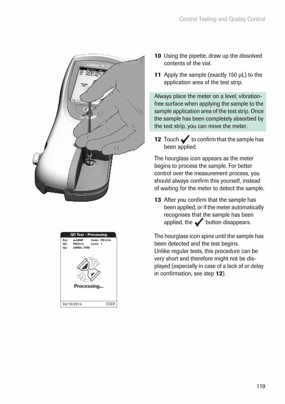
Control Testing and Quality Control
119
10 Using the pipette, draw up the dissolved contents of the vial.
11 Apply the sample (exactly 150 μL) to the application area of the test strip.
Always place the meter on a level, vibration-free surface when applying the sample to the sample application area of the test strip. Once the sample has been completely absorbed by the test strip, you can move the meter.
12 Touch to confirm that the sample has been applied.
The hourglass icon appears as the meter begins to process the sample. For better control over the measurement process, you should always confirm this yourself, instead of waiting for the meter to detect the sample.
13 After you confirm that the sample has been applied, or if the meter automatically recognises that the sample has been applied, the button disappears.
The hourglass icon spins until the sample has been detected and the test begins. Unlike regular tests, this procedure can be very short and therefore might not be dis-played (especially in case of a lack of or delay in confirmation, see step 12).
QC Test - Processing
Processing...
Level:proBNP PB1234PBC014JONES, TOM
Par:
Op:
Code:QC: 1
04/19/2014

Control Testing and Quality Control
120
The time remaining for the test is displayed.
Measurement time: The time needed to run a test depends on the test parameter (refer to package insert for details). Typically, 8 to 12 minutes are required.
The result of this quality control test is dis-played and is automatically saved to memory.
The target value and the range in which the results for this control material should be located is displayed below the current result. If a quality control test fails, an up arrow (too high) or down arrow (too low) is displayed.
There are three options for displaying a QC test result:
• Pass/Fail• Value• Value & Pass/Fail
For details refer to “QC result format” on page 81 and “Settings summary” on page 33.
Print button: Print results (infrared interface)
Menu button: Return to main menu
Comment button: Add predefined or custom comments to the test result
QC Test - Measuring
10:20 Min
Level:proBNP PB1234PBC014JONES, TOM
Par:
Op:
Code:QC: 1
04/19/2014
QC Test - Result
32901/25/2014 10:17
pg/ml(350 / 300-400 pg/ml)
Level:proBNP PB1234PBC014JONES, TOM
Par:
Op:
Code:QC: 1
Pass:
04/19/2014
QC Test - Result
49001/25/2014 10:17
pg/ml(350 / 300-400 pg/ml)
Level:proBNP PB1234PBC014JONES, TOM
Par:
Op:
Code:QC: 1
Fail:
04/19/2014
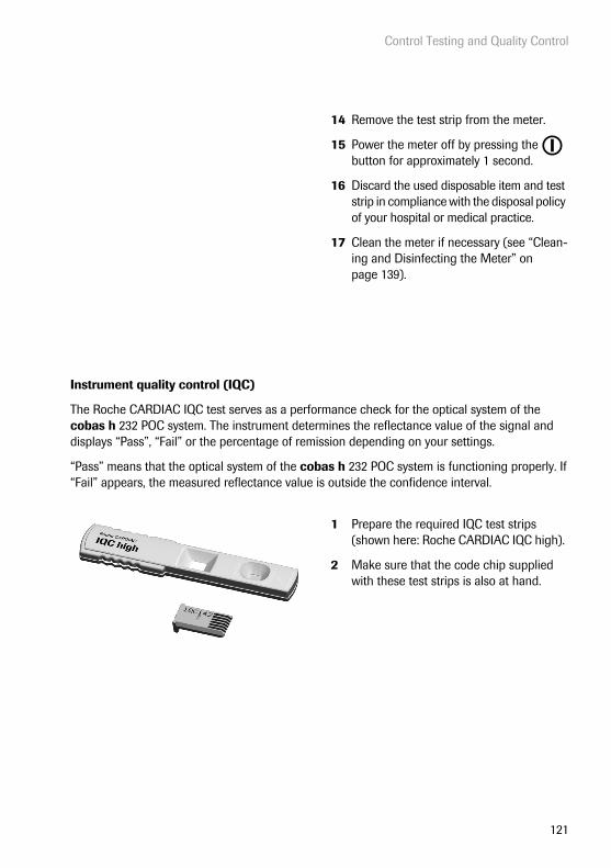
Control Testing and Quality Control
121
Instrument quality control (IQC)
The Roche CARDIAC IQC test serves as a performance check for the optical system of the cobas h 232 POC system. The instrument determines the reflectance value of the signal and displays “Pass”, “Fail” or the percentage of remission depending on your settings.
“Pass” means that the optical system of the cobas h 232 POC system is functioning properly. If “Fail” appears, the measured reflectance value is outside the confidence interval.
14 Remove the test strip from the meter.
15 Power the meter off by pressing the button for approximately 1 second.
16 Discard the used disposable item and test strip in compliance with the disposal policy of your hospital or medical practice.
17 Clean the meter if necessary (see “Clean-ing and Disinfecting the Meter” on page 139).
1 Prepare the required IQC test strips (shown here: Roche CARDIAC IQC high).
2 Make sure that the code chip supplied with these test strips is also at hand.
Control Testing and Quality Control
122
The first steps in this quality control test are identical to the procedure described before, see page 115. The following description therefore starts at the main menu.
3 Touch Control Test.
4 Touch in the QC Status screen to continue with quality control test. The test strip icon prompts you now to insert a test strip.
5 Remove the test strip from its IQC test strip container.
6 Insert the test strip as described before, see page 116.
7 If you are using a new lot of IQC test strips and have not inserted the code chip yet, you must do so now. If you have used the test strips already, skip this step.
Main Menu
Control Test
Review Results
Setup
Patient TestQC!
09:15 am
04/19/2014
QC Test - QC Status
CK-MB
QC Status
MyoDDimer
- Pass
- Pass- Pass
Trop TproBNP
- Locked- Locked
04/19/2014
QC Test - Ins. Strip
Insert Strip
JONES, TOMOp:
04/19/2014
QC Test - Ins. ChipIQC
JONES, TOM
Par:
Op:
Insert Code Chip702
04/19/2014
QC

Control Testing and Quality Control
123
The hourglass icon is displayed and the (inter-nal) measurement begins.
The result of this IQC quality control test is displayed as Pass or Fail (default setting) or in the format selected in the QC result format setting.
There are three options for displaying an IQC test result:
• Pass/Fail• Value• Value & Pass/Fail
For details refer to “QC result format” on page 81 and “Settings summary” on page 33.
QC Test - MeasuringIQC IQC702Code:
JONES, TOM
Par:
Op:Level: 1
04/19/2014
QC Test - ResultIQC Code: IQC702
JONES, TOM
Par:
Op:
11/04/2014 10:17
Level: 1
04/19/2014
83 %(85 / 82 - 88 %)

Control Testing and Quality Control
124
This page intentionally left blank.

Review Results
125
8 Review Results
The cobas h 232 meter can save 500 patient test results as well as 500 quality control tests to memory, together with time, date, lot number and, if applicable, IDs and comments.
Reviewing test results
1 Power the meter on by pressing the button for approximately 1 second.
You can also power on the meter directly by connecting the handheld power supply.
To power the meter off after use, press the button for approximately 1 second.
Depending on the system settings the opera-tor my have to log in and/or enter a password. Follow the procedures as described on page 98.
2 Wait until the main menu is displayed.Main Menu
Control Test
Review Results
Setup
Patient Test
04/19/2014
09:15 am
Review Results
126
From the Main Menu you have access to all stored results, sorted by selectable criteria:
■ Patient History
■ All Results
■ QC Results (Quality Control)
■ IQC Results (Instrument Quality Control)
■ Maintenance History
3 Touch Review Results.
4 Select the function you want to perform in the memory.
The printer icon only appears if the printer function is activated. Otherwise it is not displayed. In the following screens the printer function is activated.
Main Menu
Control Test
Review Results
Setup
Patient Test
04/19/2014
09:15 am Review Results
All Results
QC Results
IQC Results
Patient History
Mainten. History
04/19/2014
Review Results
127
Patient history
This memory area contains a list of all patients, sorted by Patient ID. From here, you can call up results for any individual patient.
1 Touch and to display the entry of choice on the screen. If the arrow is just an outline , you have reached the beginning or end of the patient list.
2 Touch the patient name whose results you want to open.
3 Touch and to display the test result of choice on the screen.
4 Touch the test result you would like to view in detail.
Pat. History - Select ID
Scan
PID001GERTA123Anders, Gert
PID001CHAPLINC123Chaplin, Charlene
PID001BERNDH123Bernd, Hans
PID001FRENZENA12Frenzen, Alice
PID230ONEALJ1234ONeal, John
04/19/2014
Single Patient ResultsPat:
proBNP 620 pg/ml02/08/14 09:49
SCHULZ, MANFREDPID111SCHULZM457
DDimer High02/12/14 08:30
DDimer 1.3 µg/ml01/21/14 09:15
04/19/2014
Pat. Test - Result
62002/08/2014 09:49
pg/ml
proBNP PB1234
SCHULZ, MANFREDJONES, TOM
Par:Op:
Code:
PID111SCHULZM457Pat:
New Strip Lot
04/19/2014

Review Results
128
All results
This memory area contains a list of all tests, sorted chronologically. From here, you can call up results for specific times.
1 Touch and to display the entry of choice on the screen.
2 Touch the patient name whose result you want to open.
The selected test result dialog box will appear.
When you touch , a list of results for the selected patient is displayed (see page 127).
All Results
Doe, John02/15 10:52 Trop-T
Zend, Nora02/15 09:40 DDimer
Smith, Adam02/15 10:11 proBNP
Smith, Bob02/14 11:40 Trop-T
Smithee, Aaron02/14 10:50 proBNP
04/19/2014
Pat. Test - Result
62002/08/2014 09:49
pg/ml
proBNP PB1234
SCHULZ, MANFREDJONES, TOM
Par:Op:
Code:
PID111SCHULZM457Pat:
New Strip Lot
04/19/2014
Review Results
129
Quality control (QC) results
This memory area contains all test parameter-specific quality control tests (QC, starting on page 115) that were run, sorted chronologically. The most recent results are at the top of the list.
1 Touch and to display the entry of choice on the screen.
2 Touch the entry you want to open.
The entry is displayed.
QC Results
DDimer L102/12/14 08:00
DDimer L202/12/14 08:30
proBNP L102/04/14 10:17
DDimer L201/10/14 07:30
DDimer High01/10/14 07:05
04/19/2014
QC Result
32904/18/2014 10:17
pg/ml(350 / 300-400 pg/ml)
Level:proBNP PB1234PBC014JONES, TOM
Par:
Op:
Code:QC: 1
Pass:
04/19/2014
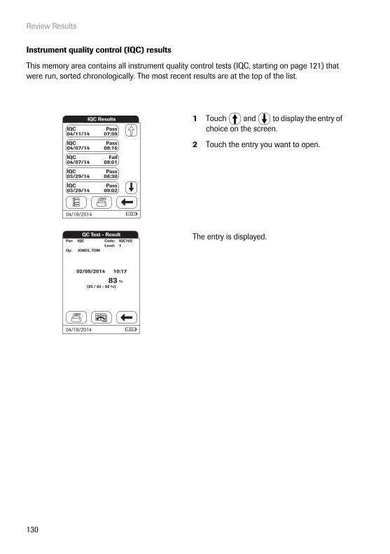
Review Results
130
Instrument quality control (IQC) results
This memory area contains all instrument quality control tests (IQC, starting on page 121) that were run, sorted chronologically. The most recent results are at the top of the list.
1 Touch and to display the entry of choice on the screen.
2 Touch the entry you want to open.
The entry is displayed.
IQC Results
IQC04/11/14
Pass07:59
IQC04/07/14
Pass08:16
IQC04/07/14
Fail08:01
IQC03/29/14
Pass08:30
IQC03/29/14
Pass09:02
04/19/2014
QC Test - ResultIQC Code:
JONES, TOM
Par:
Op:
02/08/2014 10:17
Level: 1
04/19/2014
IQC702
83 %(85 / 82 - 88 %)

Review Results
131
Maintenance history
Maintenance History actually is a list of comments. Whenever routine maintenance or service is done for the meter, this event can be stored in form of a comment. You may use the default preset comments in the meter or enter a custom comment.
1 Touch and to display the entry of choice on the screen.
Once saved, a maintenance comment can not be opened or edited. Maintenance History is (like test results) a view-only list. You can, however, add new entries:
2 Touch New.
3 Touch and to display the prede-fined comment of choice on the screen.
4 Touch the predefined comment you would like to add to the Maintenance His-tory or:
5 Touch Custom to enter your own text using the onscreen keypad.
6 Touch to save your comment.
Maintenance History
Meter Cleaned04/13/2014 08:00
Meter Cleaned04/05/2014 08:20
Meter Cleaned03/29/2014 09:00
New Battery Pack03/21/2014 08:30
Meter Cleaned03/14/2014 08:10
New
04/19/2014

Extended Functionalities
132
9 Extended Functionalities
Data handling
When used in conjunction with the Handheld Base Unit from Roche (available separately), the cobas h 232 meter can conveniently connect to a data management system (DMS). The main advantages of such a connection between meter and DMS may include:
■ Transferring patient lists, operator lists, and settings from the DMS to the meter. In this way the setup for daily work as well as general meter setup can be performed (for one or more meters) quickly and conveniently.
■ Transferring all stored test results with the corresponding Patient ID, Operator ID, and comments from the meter to the DMS. This transfer of data permits further evaluation or proper archiving according to your needs.
Through the DMS the system administrator (such as the POC coordinator) may specify what set-tings are to be applied to a set of meters within a site or unit (e.g., hospitals or wards). All meters assigned to a specific site and/or unit would consequently share the same settings. The different operator and patient lists (that match a site or unit) are then made available on their respective meters. Other settings such as QC Lockout and Operator Lockout may easily be set (once) and distributed to all meters.
Extended data handling functionality is dependent on the capabilities of the particular Data Management System (DMS) being used and may vary.
The option of setting up an Operator Lockout is available only when operator lists are created on the DMS, stored in the meter, and Operator login is activated. For more details on Operator login see page 68, for details on Operator Lockout see page 74.
Extended Functionalities
133
Computer (Setup option)
For initial connection to a DMS, the ability to communicate within a network has to be set up as follows:
■ In the Setup menu, the Connection option must be set to Computer (see page 51).
■ The Handheld Base Unit must be configured correctly. (For details please refer to the manual of the Handheld Base Unit and the Technical Note stored on the Handheld Base Unit itself.)
■ Place the meter on a Handheld Base Unit that is connected to the network. The meter will automatically be recognized by the DMS and may now be assigned to a site and/or unit managed by the DMS (if your DMS has that functionality).
■ Depending on DMS functionality available, the DMS may transfer settings and lists to the meter as well as enable test results to be transferred from the meter to the DMS.

Extended Functionalities
134
Operator lists
After powering the meter on, an Operator login may be configured. If no list is available, the options described on page 68 apply.
■ Operator is set to Optional or Required:The Operator can either log in via the onscreen keypad or a barcode scan. The use of the meter is not restricted to a predefined Operator group, so Operator IDs are entered via the onscreen keypad or read from the barcode and stored with test results for informational purposes only.
■ Operator is is set to Scan Only: The display of the meter's onscreen keypad is blocked. The Operator can only log in via a barcode scan as there is no onscreen keypad. The use of the meter is not restricted to a predefined Operator group, so Operator IDs are read from the barcode and stored with test results for informational purposes only.
Meters which are managed by a DMS may receive an Operator list.
■ Operator ID is set to List, a list is available and displayed on the login screen:The Operator selects the ID from the displayed list. If so configured by the Administrator, the Operator may also be required to enter a password to log in.
■ Operator ID is set to Hidden List:The Operator can login via a barcode scan or the onscreen keypad. If so configured by the Administrator, the Operator may also be required to enter a password to log in.
When working with operator lists: The use of the meter is restricted to the operators on this list.
Extended Functionalities
135
Patient lists
When starting a Patient Test, there will be the option of either selecting a Patient ID from a patient list, entering the Patient ID using the onscreen keypad or, if available, of scanning the barcode with the Patient ID. The Patient ID, if entered on the DMS, comes with an additional identification entry. Up to 20 characters can be used and assigned as a second confirmation (e.g., name, date of birth).
There are four possible configurations for a Patient ID input:
■ The Patient ID is set to Optional or Required, and there is no list available:A Patient ID can be entered manually via the onscreen keypad or read in via a barcode scan. The Patient ID is stored with the test result.
■ The Patient ID is set to No, but there is a list available:The list of Patient IDs is always shown when starting a test. You may now
– select a patient from the list;– scan a Patient ID using the barcode scanner;– create a new patient entry by touching New. Instead of an ID a consecutive number will
be assigned to this result.
■ The Patient ID is set to Optional or Required, and there is a list available:The list of Patient IDs is always shown when starting a measurement. You may now
– select a patient from the list;– scan a Patient ID using the barcode scanner;– create a new patient entry by touching New. You may either read the ID using the bar-
code scanner or enter a new ID via the onscreen keypad.
■ The Patient ID is set to Hidden List (only possible with a data management system), and there is a list available:An empty list is shown when starting a measurement. You may now
– scan a Patient ID using the barcode scanner;– create a new patient entry by touching New. You may either read the ID using the bar-
code scanner or enter a new ID via the onscreen keypad.
When working with Patient lists, you have the following options:
■ A Patient ID does not have to be on the list to be scanned and used.
■ The meter displays a warning that the Patient ID scanned is not on the list.
■ The meter displays an error message that the ID was not found on the list of valid Patient IDs. You must enter a valid ID to proceed.
Extended Functionalities
136
Barcode scanner
Using a DMS, the barcode scanner may be configured to accept only selected barcode symbol-ogies. Furthermore, it is possible to define a barcode mask for Patient ID and Operator ID. With masks being defined, the meter checks a barcode after scanning and rejects it, if it does not match the mask. See “Example of barcode symbologies” on page 151 for further information.
Stored test results and comments
When performing a test, the test result will be stored along with additional information, including the Patient ID, Operator ID, the kind of test performed, and optional Comments. The meter comes with a default set of Comments that can be assigned to each test result. If you are working with a DMS, these comments can be replaced by the comments in the DMS. The new wording will then be available for selection from the Comments list in the meter.
Up to 3 comments can be assigned to each result.
The Comment function may be configured to be either optional, required for test results which are out of range, or always required. If the user is required to enter/select a comment, com-pletely empty comments will not be accepted by the meter.

Extended Functionalities
137
The default preset comments in the meter are:
Patient and QC Result comments Maintenance comments
■ Symptomatic
■ Asymptomatic
■ Chest Pain
■ Dyspnea
■ Intermediate Zone
■ Doctor Notified
■ RN Notified
■ Under Medication
■ Will Repeat Test
■ No Action
■ New Strip Lot
■ New Strip/Kit Lot
■ New Lot Number
■ Lab Draw
■ Cleaned Meter
■ Switched QC Vial
■ Repeat Control Test
■ Acceptable Control
■ New Control Lot
■ Procedure Error
■ Meter Cleaned
■ Samp. App. Area Cl. (Sample Application Area Cleaned)
■ Test Strip Guide Cl. (Test Strip Guide Cleaned)
■ New Battery Pack

Extended Functionalities
138
This page intentionally left blank.

Cleaning and Disinfecting the Meter
139
10 Cleaning and Disinfecting the Meter
■ Make sure the meter is powered off. Unplug the power supply unit and remove the hand-held battery pack.
■ Use only ordinary lint-free cotton swabs/buds and lint-free tissues.
■ Ensure that cloth or swab/bud is only damp, not wet, to protect against moisture entering the meter.
■ Do not spray anything onto the meter and do not immerse it in liquid.
■ Observe the disinfection guidelines of your institution.
■ Use gloves.
NOTICE Follow the procedures below to clean/disinfect the meter. Failure to follow these procedures may cause malfunction of the meter.

Cleaning and Disinfecting the Meter
140
Recommended cleaning/disinfecting solutions
Use only the following solutions for cleaning/disinfecting the meter (housing and the test strip guide cover).
■ Ammonium chloride solution (2 %)
■ Diluted bleach solution (1:10)
■ Mild soapy water
■ Citric acid (2.5 %)
■ Hydrogen peroxide (0.5 %)
■ Sodium hypochlorite solution (0.6 %)
■ 70 % isopropyl alcohol
Cleaning/disinfecting the exterior (meter housing)
Clean the meter whenever it becomes dirty. You can also use the device-specific “Cleaning Lockout” function (see page 85) to ensure regular checks are performed.
Use only the solutions recommended above.
Basic sequence of steps for cleaning
■ First remove any blood and other dirt using water or soapy water.
■ Then disinfect the meter's housing.
NOTICE Do not use any other disinfectants/cleaning solutions on the meter (housing or the test strip guide cover). Use of other disinfectants/clean-ing solutions could result in damage to the meter.
Refer to the safety information provided on the packaging of the prod-ucts when using the chemical cleaning agents mentioned above. Some of the agents must not be used together as this may result in undesirable reactions. Follow the manufacturer's instructions.

Cleaning and Disinfecting the Meter
141
Cleaning after contamination due to mispipetting
Observe the following precautions to prevent instrument damage
■ Do not move the meter to prevent liquids from creeping and penetrating the meter.
■ Dab away all visible blood (also on the test strip, but not in the application area).
■ Do not use the meter before the liquid/moisture has been completely removed. While it is drying, the meter must not be moved as this may soil the optical components.
For detailed cleaning instructions (“how to clean…”) for the individual components of the meter, see the following pages. The instructions below describe only the sequence of steps to be taken in case of mispipetting.
■ Remove the test strip guide cover.
■ Remove and dispose of the test strip.
■ Clean the soiled parts of the meter with a moistened cotton swab/bud or tissue.
■ Disinfect the meter.

Cleaning and Disinfecting the Meter
142
Cleaning the test strip guide cover
1 If required, remove the meter from the Handheld Base Unit and place it horizon-tally on a table.
2 Remove the test strip guide cover by pull-ing it forward horizontally (in the direction of the arrow).
Move the cover safely away from the meter and wipe it clean using the solu-tions recommended above.
In case of significant soiling or contami-nation, you can rinse the test strip guide cover with warm water, dry it with a fresh tissue, and then disinfect it using the solu-tions recommended on page 140.
Always ensure that the test strip guide cover is completely dry before re-attach-ing it to the meter.
3 Clean the outside of the meter with a lightly moistened tissue. Then dry the meter with a fresh tissue.

Cleaning and Disinfecting the Meter
143
Cleaning the visible area of the test strip guide
1 Clean the easily accessible and visible pipetting field area of the test strip guide with a moistened cotton swab/bud or tissue. Then dry the test strip guide with a fresh tissue.
Adhere to the following:
■ Clean only the visible area of the test strip guide.
■ Do not insert any objects into the con-cealed areas of the test strip guide as this will damage the optical components of the meter.
■ Do not use objects to try to scratch off any dried contaminants in the test strip guide.
2 Clean the membrane (small circle) in the visible area at the end of the test strip guide with a moistened cotton swab/bud or tissue.
3 Allow the inside of the test strip guide to dry for about 10 minutes.
4 After this time, re-attach the test strip guide cover to the housing. Make sure that the cover is properly attached. You will feel it snap into place.

Cleaning and Disinfecting the Meter
144
This page intentionally left blank.

Troubleshooting
145
11 Troubleshooting
The cobas h 232 meter continually checks its systems for unexpected and unwanted conditions. These may arise for technical reasons (defective components or consumables, environmental factors) or due to handling and procedure errors.
Depending on the circumstances, a message may appear on the display of the meter. These messages are marked with an icon, either for a status message, or for an error mes-sage. All messages displayed by the system are accompanied by a description of the error and a possible solution.
Take the action suggested on screen to resolve the problem. If the error disappears, you may continue using the meter as desired. If the problem persists, contact Roche (see page 152).
The two different message types are illustrated below:
Message Description
I-001: Battery Low
Status message
Touch to proceed with the next step.
E-101: Patient ID Required
Error message
Touch to exit this message. Perform the suggested step(s) to solve the problem.
Battery Low
The battery is getting low. Replace or recharge battery pack as soon as possible.
I-001
Patient ID Required
A patient ID is required. Enter a valid patient ID.
E-101

Troubleshooting
146
Errors and unusual behavior without error messages
Some conditions may arise that have no associated error or status message.
Message Description
No message or unusual behavior
Meter display does not power on
■ Wait 10 seconds and try powering on the unit again.
■ Check that the meter has power.• If you are using the external power supply unit, is it connected
properly to the meter?Or:
• Place the meter in the Handheld Base Unit.Or:
• If you are using the Handheld Battery Pack, is it properly installed in the meter?
Meter displays an unexpected result
Refer to the package insert for the test strips.
Automatic shutdown
The meter powers off after a configurable time without activity (e.g., pressing a key, touching the screen) to conserve energy. Reactivate the meter/screen as described in the following:
Shutdown after time spec-ified by system administra-tor (default is 5 minutes, configurable by system administrator)
■ Press the On/Off button of the meter.

General Product Specifications
147
12 General Product Specifications
12.1 Operating conditions and technical data
Technical data
Temperature range 18-32 °C
Relative humidity 10-85% (no condensation)
Maximum altitude 4000 m
Position Always place the meter on a level, vibration-free surface when applying the sample to the sample application area of the test strip. Once the sample has been completely absorbed by the test strip, you can move the meter.
Measuring range Depends on test parameters
Memory 500 Patient Test Results500 QC Test Results200 IQC Test Results100 Strip Code Chips100 QC Code Chips500 Patient List entries200 Operator List entries
Interface Infrared interface, LED/IRED Class 1
Battery operation Handheld battery pack
Mains connection Power supply adapter: Input: 100-240 V AC (± 10%) / 50-60Hz / 350-150 mAOutput: 7.5 V DC / 1.7 A
Number of tests with fully charged battery
approx. 10 tests
Safety class III
Automatic power-off Programmable 1 … 60 minutes
Dimensions 275 102 55 mm
Weight approx. 650 g incl. handheld battery pack and scanner
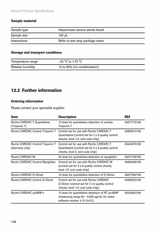
General Product Specifications
148
Sample material
Storage and transport conditions
12.2 Further information
Ordering information
Please contact your specialist supplier.
Sample type Heparinized venous whole blood
Sample size 150 μL
Interactions Refer to test strip package insert
Temperature range –25 °C to +70 °C
Relative humidity 10 to 85% (no condensation)
Item Description REFRoche CARDIAC T Quantitative (Troponin T)
10 tests for quantitative detection of cardiac Troponin T
04877772190
Roche CARDIAC Control Troponin T Control set for use with Roche CARDIAC T Quantitative (control set for 2 x 6 quality control checks, level 1/2, and code chip)
04890515190
Roche CARDIAC Control Troponin T (Germany only)
Control set for use with Roche CARDIAC T Quantitative (control set for 2 x 6 quality control checks, level 2, and code chip)
05453879190
Roche CARDIAC M 20 tests for quantitative detection of myoglobin 04877799190
Roche CARDIAC Control Myoglobin Control set for use with Roche CARDIAC M (control set for 2 x 6 quality control checks, level 1/2, and code chip)
04890469190
Roche CARDIAC D-Dimer 10 tests for quantitative detection of D-Dimer 04877802190
Roche CARDIAC Control D-Dimer Control set for use with Roche CARDIAC D-Dimer (control set for 2 x 6 quality control checks, level 1/2, and code chip)
04890523190
Roche CARDIAC proBNP+ 10 tests for quantitative detection of NT-proBNP (measuring range 60 - 9,000 pg/mL for meter software version ≥ 01.04.01)
05533643190
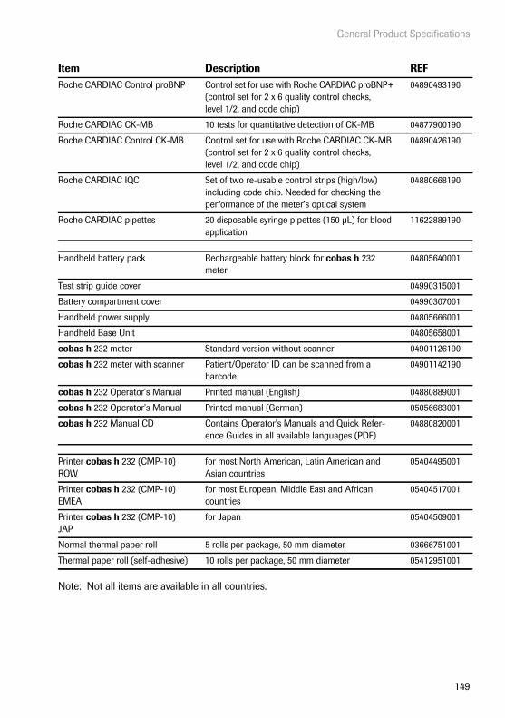
General Product Specifications
149
Note: Not all items are available in all countries.
Roche CARDIAC Control proBNP Control set for use with Roche CARDIAC proBNP+(control set for 2 x 6 quality control checks, level 1/2, and code chip)
04890493190
Roche CARDIAC CK-MB 10 tests for quantitative detection of CK-MB 04877900190
Roche CARDIAC Control CK-MB Control set for use with Roche CARDIAC CK-MB (control set for 2 x 6 quality control checks, level 1/2, and code chip)
04890426190
Roche CARDIAC IQC Set of two re-usable control strips (high/low) including code chip. Needed for checking the performance of the meter’s optical system
04880668190
Roche CARDIAC pipettes 20 disposable syringe pipettes (150 μL) for blood application
11622889190
Handheld battery pack Rechargeable battery block for cobas h 232 meter
04805640001
Test strip guide cover 04990315001
Battery compartment cover 04990307001
Handheld power supply 04805666001
Handheld Base Unit 04805658001
cobas h 232 meter Standard version without scanner 04901126190
cobas h 232 meter with scanner Patient/Operator ID can be scanned from a barcode
04901142190
cobas h 232 Operator’s Manual Printed manual (English) 04880889001
cobas h 232 Operator’s Manual Printed manual (German) 05056683001
cobas h 232 Manual CD Contains Operator’s Manuals and Quick Refer-ence Guides in all available languages (PDF)
04880820001
Printer cobas h 232 (CMP-10) ROW
for most North American, Latin American and Asian countries
05404495001
Printer cobas h 232 (CMP-10) EMEA
for most European, Middle East and African countries
05404517001
Printer cobas h 232 (CMP-10) JAP
for Japan 05404509001
Normal thermal paper roll 5 rolls per package, 50 mm diameter 03666751001
Thermal paper roll (self-adhesive) 10 rolls per package, 50 mm diameter 05412951001
Item Description REF

Warranty
150
Product limitations
Please read the information in the package insert supplied with the test strips for detailed product data and limitations.
Information about software licenses
This product incorporates software modules developed under open source licenses. The source code of this software can be requested on a standard data exchange medium from the manufac-turer at the following address:
Roche Diagnostics GmbHSandhofer Str. 11668305 Mannheim, Germany
The General Public License (GPL) licensing conditions are available (in English only for legal rea-sons) as a text file (file name “License_txt.PDF”) on the CD supplied with this manual. The com-plete license agreements are also stored as a text file (file name “license.txt”) on the Handheld Base Unit. You can access this file by connecting the base unit to a PC with the USB cable. For detailed instructions on how to do this, see the Operator's Manual of the Handheld Base Unit.
Everyone is permitted to copy and distribute verbatim copies of this license document, but changing it is not allowed.
Repairs
Please note that repairs and other modifications to the meter may only be performed by persons authorized by Roche.
Contact Roche
For all questions about the cobas h 232 POC system that are not answered in this manual, contact your Roche representative. If you do not already have contact details, a list of Roche Diagnostics offices is provided in the appendix or visit our website at www.Roche.com. Select “Roche in your country” at the top of the page and then select your country to find the appropriate local office contact information.
13 Warranty
The statutory guarantee provisions on rights in consumer goods sales in the country of purchase shall apply.

Appendix
151
14 Appendix
14.1 Example of barcode symbologies
When creating patient or operator barcodes, always adhere to the applicable international IEC/ISO standards for the respective barcode symbology. In particular, ensure that barcode size and print quality (as defined in ISO/IEC 15421) are adequate. Inadequate print size and/or quality may lead to erroneous decoding.
Codabar
Code 39
Code 93
Code 128
Interleaved 2 of 5
Appendix
152
14.2 Contact Roche
If you have any further questions, please contact your local customer support and service center.
Argentina Productos Roche SAQeIRawson 3150B1610BAL Ricardo Rojas, TigreBuenos Aires – ArgentinaTel.: +54 (11) 5129 8000
Australia Roche Diagnostics Australia Pty Ltd.ABN 29 003 001 20531 Victoria AvenueCastle Hill, NSW, 2154Telephone 02-9860 2222 or 1800 645 619
Austria Roche Diagnostics GmbHEngelhorngasse 3A-1211 WienTel. +43-1-27787-555www.roche.at
Belgium Roche Diagnostics BelgiumSchaarbeeklei 198BE-1800 VilvoordeTel : +32 2 247 47 47Fax : +32 2 247 46 80www.roche-diagnostics.be
Brazil Roche Diagnóstica Brasil Ltda.Av. Engenheiro Billings, 1729 – prédio 3805321-900 São Paulo, SP, BrasilTel. +55 11 3719 8888Fax +55 11 3719 8555
Canada Roche Diagnostics201 Armand-Frappier BoulevardLaval, Quebec (Canada) H7V 4A2Technical Support for Healthcare Institutions: Region of Montreal 450-686-7111Roche Care Center (toll free) 1-877-273-3433www.rochediagnostics.ca
Central America& The Caribbean
Roche Diagnostics Central America & The CaribbeanEdificio Capital Plaza, Piso 18Calle Paseo del Mar, Costa del EstePanama, Rep. de Panama Tel. + 507 378 1295

Appendix
153
Chile Roche Chile Ltda.Avda. Quilín 3750Macul, SantiagoTel.: +56 (2) 4413200
China 罗氏诊断产品(上海)有限公司 Roche Diagnostics (Shanghai) Limited 上海市淮海中路 1045号淮海国际广场 12楼 12/F, Huaihai Plaza, No. 1045, Central Huaihai Road Shanghai, 200031, P.R. ChinaTel. +86 21 2412 1000Fax +86 21 2412 1188
Colombia Productos Roche S.A.Carrerra. 44 No. 20-21Apartado Aéreo 80372Bogota, D.C.
Croatia DobavljačMEDICAL INTERTRADE d.o.o.Dr. F. Tuđmana 310431 Sveta Nedelja, HrvatskaTel.: 00385 1 3374 010
Dodatne informacije:Roche Diagnostics Deutschland GmbHPredstavništvo u Republici HrvatskojBanjavčićeva 22/II10000 Zagreb, HrvatskaTel.: 00385 1 4628 360
Czech Republic Roche s.r.o., Diagnostics DivisionKarlovo náměstí 17120 00 Praha 2Česká republikawww.roche-diagnostics.czTel.: +420 220 382 500
Denmark Roche Diagnostics A/SIndustriholmen 592650 HvidovreDanmarkTel.: 36 39 98 98Fax: 36 39 99 79www.roche.dk
Ecuador Roche Ecuador S.A.Av. 10 de Agosto N36-239 y Naciones UnidasQuitoTel.:+593 (2) 2434347

Appendix
154
Estonia Surgitech ASPirita tee 20T10127 TallinnTel: +372 6460660
Finland Roche Diagnostics OyKlovinpellontie 3, PL 160, 02181 EspooPuhelinvaihde: 010 554511Suomi
France Roche Diagnostics2, Avenue du Vercors, B.P. 5938242 Meylan CedexTel : +33 4 76 76 30 00www.rochediagnostics.fr
Germany Roche Diagnostics Deutschland GmbHKundenservice CenterSandhofer Straße 11668305 MannheimTel.-Nr. +49 (0) 621 759 4747
Greece Roche Diagnostics (Hellas) A.E.Ακακιών 54Α151 25 Μαρούσι Aττικής, ΕλλάδαΤηλ.: +30-210-8174000Γραμμή Υποστήριξης: +30 801 11 61008 & +30 210 8174199
Hungary Roche Magyarország Kft.2040 Budaörs, Edison u. 1MagyarországTel:+36-23-446-886Fax:+36-23-446-890Meghibásodás esetén hívható ingyenes zöld szám (2014. szeptembertől): 06 80 200 089
Italy Roche Diagnostics SpAViale G. B. Stucchi 11020052 Monza (MI) ItaliaNumero Verde: 800-610619www.roche-diagnostics.it
Latvia SIA „Medilink“Viskaļu iela 11,Rīga, LV 1026Tālr. 67840379, 67840380

Appendix
155
Lithuania UAB „Roche Lietuva“ Diagnostikos padalinysJ.Jasinskio g. 16BLT-01112 Vilnius, LietuvaTel. +370 5 254 6777Faks. +370 5 254 6778
Mexico Productos Roche, S.A. de C.V.Cerrada de Bezares 9Col. Lomas de BezaresDel. Miguel HidalgoMéxico D.F., 11910Tel.: +52 55 50 81 58 00
Netherlands Roche Diagnostics Nederland BVTransistorstraat 411322 CK Almere, NederlandTel.: 0800 2 882 882www.roche-diagnostics.nl
New Zealand Roche Diagnostics N.Z. Ltd,15 Rakino Way, Box 62-089Mt. Wellington, AucklandTelephone +64 9 276 4157 Toll Free 0800 652 634
Norway Roche Diagnostics Norge ASBrynsengfaret 6BPb 6610 Etterstad0607 Oslo, NorgeTel. +47-23373300www.roche.no
Poland Roche Diagnostics Polska Sp. z o.o.ul. Wybrzeże Gdyńskie 6 B01-531 Warszawa, PolskaTel. +48-22-481 55 55www.roche.pl
Portugal Roche Sistemas de Diagnósticos, LdaEstrada Nacional, 249-12720-413 Amadora, PortugalTelefone: +351-21-417 1717www.roche.pt

Appendix
156
Russia ООО «Рош Диагностика Рус»Официальный дистрибьютор«Ф. Хоффманн Ля Рош Лтд.» (Швейцария)Россия, 115114, г. Москва,ул. Летниковская, д. 2, стр. 2, Бизнес Центр «Вивальди Плаза»Тел.: +7 (495) 229-69-99, +7 (495) 229-29-99Факс: +7 (495) 229-62-64http://www.rochediagnostics.ru
Slovakia Roche Slovensko, s.r.o.Diagnostics DivisionLazaretská 12811 08 Bratislava, Slovenská republikawww.roche-diagnostics.comTel.: +421-2-5710 3680Fax: +421-2-5263 5213
Slovenia Roche farmacevtska dru�ba d.o.o.Divizija za diagnostiko.Vodovodna cesta 1091000 Ljubljana, SlovenijaTelefon Centra za pomoč uporabnikom in servis: 080 12 32
South Africa Roche Products (Pty) Ltd. South AfricaDiagnostics Division9, Will Scarlet Road / FerndaleP.O. Box 1927, Randburg 2125 Telephone +27 -11 504-4600
Spain Roche Diagnostics S.L.Avda. de la Generalitat, 171, 17308174 Sant Cugat del Vallès (Barcelona)Teléfono: 902 43 33 33Internet: www.roche.es
Sweden Roche Diagnostics Scandinavia ABBox 14716126 Bromma, SverigePhone Nr.: +46 (0)8 404 88 00www.roche.se
Switzerland Roche Diagnostics (Schweiz) AGIndustriestraße 7CH-6343 RotkreuzTel. +41-41-799 61 61www.roche-diagnostics.ch

Appendix
157
Turkey Roche Diagnostik Sistemleri Ticaret A.Ş.Gazeteciler Sitesi – Matbuat Sokak No. 334394 Esentepe – IstanbulTürkiyeTel: +90-212-306.06.06
United Kingdom Roche Diagnostics Ltd.Charles AvenueBurgess Hill, RH15 9RYUK Freephone: 0808 100 99 98Rep. of Ireland Freephone: 1800 509 586
Uruguay Roche International Ltd.(Diagnostics Division)Solferino 409611400 MontevideoTel.: +598 (2) 6137888
USA Roche Diagnostics9115 Hague RoadIndianapolis, IN 46256Service informationFor technical assistance or information, contact the Accu-Chek® Customer Care Service Center at 1-800-440-3638, 24 hours a day, 365 days a year.

Appendix
158
This page intentionally left blank.

Supplement for Observed Test Sequence
159
15 Supplement for Observed Test Sequence
Observed Test Sequence (OTS)
The Observed Test Sequence (OTS) function allows an observer (supervisor) to assess and record an operator’s performance (e.g., for recertification purposes). The observer monitors an operator during a test to check that the test is being performed according to the recommended proce-dures. He/she then evaluates the performance and passes or fails the operator. This assessment is saved together with the test result and any desired comments.
Observed Test Sequence options can only be configured using a DMS. The availability of electronic configuration options will thus vary according to the data management software utilized by your institution. Consult your system administrator.

Supplement for Observed Test Sequence
160
Using the OTS function
A request for an Observed Test Sequence comes from the DMS. The presence of the icon on the Patient Test button indicates a pending OTS request.
Observer:
1 Touch Patient Test.
In the Pat. Test -OTS menu, the Patient Test button is grayed out (disabled) until the observer has logged in.
2 Touch Observer Login.
3 Wait until the observer list is displayed.
4 Select your observer ID by touching the corresponding button, or scan your operator ID (which is also your observer ID in this case)..
Only operators with OTS observer rights are listed in the Observer Login list.
5 Enter the (optional) password.
6 After you enter your password, touch to log in. The Pat. Test - OTS menu is dis-played again. The Patient Test button is now active.
7 Hand the meter to the operator who can now perform the patient test under supervision.
Main Menu
Control Test
Review Results
Setup
Patient Test
Logout
09:15 am
04/19/2014
Pat. Test - OTS 09:15 am
04/19/2014
Observer Login
Patient Test
OTS enabled
Observer 09:15 am
04/19/2014
Ann Casey
Alan Smithee
ScanPat. Test - OTS 09:15 am
04/19/2014
Observer Login
Patient Test
OTS enabled
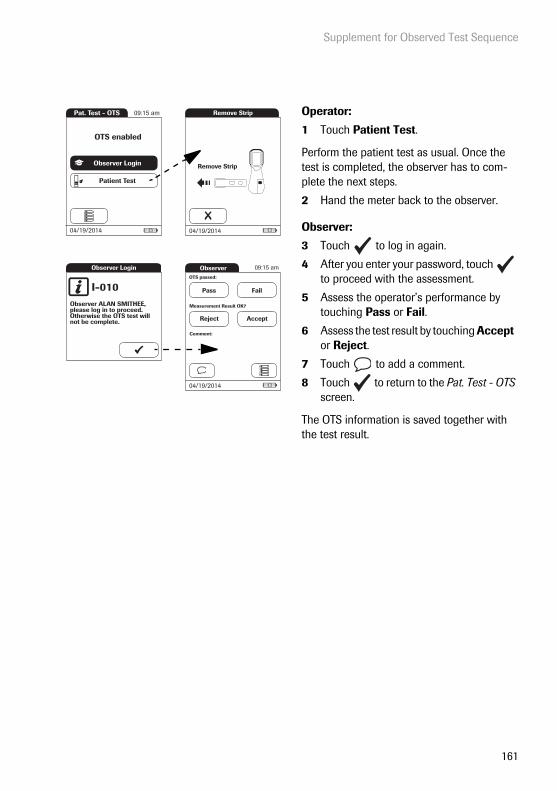
Supplement for Observed Test Sequence
161
Operator:
1 Touch Patient Test.
Perform the patient test as usual. Once the test is completed, the observer has to com-plete the next steps.
2 Hand the meter back to the observer.
Observer:
3 Touch to log in again.
4 After you enter your password, touch to proceed with the assessment.
5 Assess the operator’s performance by touching Pass or Fail.
6 Assess the test result by touching Accept or Reject.
7 Touch to add a comment.
8 Touch to return to the Pat. Test - OTS screen.
The OTS information is saved together with the test result.
Pat. Test - OTS 09:15 am
04/19/2014
Observer Login
Patient Test
OTS enabled
Observer Login
I-010Observer ALAN SMITHEE,please log in to proceed. Otherwise the OTS test will not be complete.
Measurement Result OK?
Reject Accept
Comment:
Observer
04/19/2014
OTS passed:
Pass Fail
09:15 am
Remove Strip
Remove Strip
04/19/2014

Supplement for Observed Test Sequence
162
This page intentionally left blank.

Index
163
16 Index
AAdministrator ..................................................... 62Administrator ID
Change ......................................................... 66Disable ......................................................... 67Set up .................................................... 62–65
Application area ............................................... 19Apply sample ................................................... 106
Opening (meter) ....................................... 17Auto off ................................................................ 48
BBarcode ......................................................98, 103
Symbologies ............................................. 151Barcode (test strip) .......................................... 19Barcode reader ................................................. 19Barcode scanner .............................................. 17Basics (setup) ............................................. 35–49Battery pack ....................................................... 24
CCleaning .................................................. 139–143
After mispipetting .................................. 141Cleaning agents ...................................... 140Housing - outside .................................. 142Test strip guide ....................................... 143
Cleaning lockout .............................................. 85cobas h 232
Contents of the pack .............................. 10Introduction ...................................................9Operating conditions ............................ 147Overview of meter elements ......... 16–18Test principle ............................................. 10
cobas IT 1000 .......................................................9Code chip .............................................. 19, 93–94
Opening ....................................................... 18Comment (custom) ....................................... 111Comment result .............................................. 111Computer ............................................50–51, 133Connection .................................................. 50–53Contact Roche ................................................ 152
Contents of the pack .......................................10Contrast .........................................................35–36Control material .............................................. 114Custom range .............................................82, 83
DData handling .............................................50–60Data Management System (DMS) .... 56, 62, 70, ................................................................. 71, 132Data transfer ................................................... 132Date ................................................................39–40Display format .............................................43–44Disposal .........................................................13, 92
EError messages ............................................... 145
HHandheld battery pack ............................17, 23
Insert .......................................................25–26
IIcons: see SymbolsID setup .........................................................61–72
Overview ......................................................61Infections (safety instructions) ....................92Infrared interface .................................... 18, 132IQC lockout .........................................................80
LLanguage ......................................................37–38Laser ......................................................................17Lockout ..........................................................73–87
Cleaning lockout .......................................85IQC lockout .................................................80New lot lockout .........................................79Operator lockout ................................74–76QC lockout ..................................................79

Index
164
MMeter setup
Administrator ID ................................ 62–65Auto off ........................................................ 48Basics .................................................... 35–49Cleaning lockout ...................................... 85Computer ............................................. 50–51Contrast ................................................ 35–36Data handling ..................................... 50–60Date ........................................................ 39–40Display format .................................... 43–44ID setup ................................................ 61–72IQC lockout ................................................. 80Language ............................................. 37–38Lockout ................................................. 73–87New lot lockout ......................................... 79Operator ID .......................................... 68–70Operator lockout ............................... 74–76Optional screens ................................ 88–90Overview ............................................... 30–34Patient ID .............................................. 71–72Printer .................................................... 52–53QC lockout .................................................. 79QC result format ................................ 81, 82Reset test parameters ............................. 84Result confirmation ................................. 90Result display mode ......................... 59–60Result login ................................................. 89Result memory ................................... 54–56Result unit ............................................ 57–58Sound .................................................... 45–47Start info ...................................................... 89STAT test ..................................................... 86Time ........................................................ 41–42
NNew lot lockout ................................................. 79
OObserved Test Sequence (OTS) ...... 159–161On/Off button .................................................... 17Operating conditions ....................................147Operating the meter ................................. 23–26Operator ID ....................................68–70, 97–99Operator list ...............................................98, 134
Operator lockout ....................................... 74–76Optional screens ....................................... 88–90Ordering information .................................... 148Overview of meter elements ................. 16–18
PPatient ID .................................. 71–72, 101–103Patient list ...................................... 101–103, 135Power supply ......................................................24
Contacts (Handheld Base Unit) ..........18Power supply unit
Connection .......................................... 18, 20Powering on the meter ............... 96, 115, 125Printer ............................................................ 52–53Product specifications ................................. 147
QQC lockout ..........................................................79QC result format ........................................ 81, 82Quality control ........................................113–123
Control material ...................................... 114IQC (instrument-specific) ..........121–123Pass/Fail .................................................... 123Preparation ............................................... 113QC (test parameter-specific) ....115–121
RReset button .......................................................18Reset test parameters .....................................84Result confirmation ................................ 90, 110Result deletion (automatic) ...........................56Result display mode ................................ 59–60Result login ............................................... 89, 109Result memory ..................................54–56, 125Result unit ................................................... 57–58Review results ........................................125–137
All results .................................................. 128Data transfer ............................................ 132IQC (instrument quality control) ...... 130Maintenance ............................................ 131Patient history ......................................... 127QC (quality control) .............................. 129
Index
165
SSafety
Protection against infection ................. 12User qualification ..................................... 12
Sample material .......................................92, 148Scan (button) ............................................98, 103Self-check (powering on the meter) ........ 96Software license ............................................. 150Sound ............................................................ 45–47Specifications .................................................. 147Start info .............................................................. 89STAT Test ............................................................ 73
Perform ...................................................... 112STAT test
Configure .................................................... 86Storage and transport conditions ............ 148Symbols
Code chip ........................................ 105, 117Error messages ....................................... 145Hourglass ...............................107, 119, 120Meter ...............................................................4Packaging ......................................................4Pipette .............................................. 105, 118Screen ................................................... 21–22Thermometer ................................. 105, 118
TTest ...............................................................91–112
Performing ...................................... 100–112Preparing .............................................. 93–99Sample material ........................................ 92
Test area .............................................................. 19Test principle ..................................................... 10Test steps (overview) ...................................... 95Test strip
Inserting ........................................... 104, 116Lot .................................................................. 77
Test strip guide ................................................. 18Test strip guide cover ..................................... 17Time ............................................................... 41–42Touchscreen ............................................... 17, 29Troubleshooting .............................................. 145

Index
166
This page intentionally left blank.


0 48
8088
9001
(04
) 20
14-0
5 EN
ROCHE CARDIAC, COBAS, COBAS H and IQC are trademarks of Roche.
Roche Diagnostics GmbHSandhofer Strasse 11668305 Mannheim, Germany
www.roche.com
www.poc.roche.com