Citation Doc URL bulletin ... · PDF fileSynopsis The effect of U type and V type lapped...
11
Instructions for use Title On Special Types of Lapped Joints of Deformed Bars to be Used for Precast Slabs Author(s) Yokomichi, Hideo; Fujita, Yoshio Citation Memoirs of the Faculty of Engineering, Hokkaido University = 北海道大学工学部紀要, 13(Suppl): 83-92 Issue Date 1972-05 Doc URL http://hdl.handle.net/2115/37911 Type bulletin (article) File Information 13Suppl_83-92.pdf Hokkaido University Collection of Scholarly and Academic Papers : HUSCAP
Transcript of Citation Doc URL bulletin ... · PDF fileSynopsis The effect of U type and V type lapped...

Instructions for use
Title On Special Types of Lapped Joints of Deformed Bars to be Used for Precast Slabs
Author(s) Yokomichi, Hideo; Fujita, Yoshio
Citation Memoirs of the Faculty of Engineering, Hokkaido University = 北海道大学工学部紀要, 13(Suppl): 83-92
Issue Date 1972-05
Doc URL http://hdl.handle.net/2115/37911
Type bulletin (article)
File Information 13Suppl_83-92.pdf
Hokkaido University Collection of Scholarly and Academic Papers : HUSCAP
83
Japan--U.S. Science SeninarAugust 23-27, 1971Seattle, U.S.A.
On Special Types of Lapped Joints of Deformed Bars to be Used for Precast Slabs
12 By Hideo YOKOMICHI , Yoshio PUJITA and
Synopsis
The effect of U type and V type lapped joints of deformed bars, whieh wereproposed by the authors for the purpose of decreasing field eoncrete o:f aprecast slab bridge, on fatigue behavior and statical strength of reinforeedconcrete beams was investigated. Beams with ,conventional lapped jo;nts of barsand with no-joint bars were also tested for comparison. The results showedthat the proposed types of lapped joints were avai}able enough for practical:g?6..g2e,gl:O¥gB!g,g:i.ggff`g:,Og.Sgg,ggi:g ,y.fi}:.presented in steei stresses ,f
.t ' tt ' tt Keywords: lapped joint of bar; defoimed btir; flexural strength; fatigue;deflection; cracking; reinforced eoncrete,i beam; precast slab.
.t tt ' ' tt tt
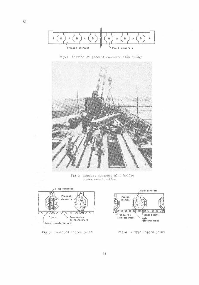
rntroduction A number of precast concrete slab bridges were construeted in Hokkaidogt2fig.tgx:tg,xg¥r.s(igo(Bx・ ,?,cg:g`s:・ g?;3? si:t2:,ghg;g,g:S,2:XSgP,eS.B;.8h:.,.,.
as shown in Ng.3 were adapted for the purpose of decreasing field eoncrete.The authors carried out investigation (2) (l956) on statical flexural behaviorof the reinforced concrete beams using U type end V type (Pig,4) lapped jointsfor a round bar of nominal yield point of 24kg/nf, and showed their availabili-ty as the joints of transverse reinforcements of precast s!abs. Mhe presentpaper describes the flexural test results on the reinforced concrete beams usingthe above mentioned types of no-hook iapped joints for a high strength deformedbar concerning fatigue and statieal strength, deflection and craeking of beam.
Materials and Test Procedure The early strength Portland eement was used. Seashore sand of 5.l9 fine-l・l9SSth{gOdt".l.UtSha."dd.rZg- V.e."..ffr/a.".e.ld O.f.t2j 5.Mi.nfMalX. ig" li"IgyS::eig"hetTe.U;i2dightT:ef C.O,".C.".ette.f"Sed
280kg/mY concrete, a water/cement ratio of O.55 and compressive strength of 348
lo, 2# Professor ofUniversity
Concrete and Reinforced Concrete Engineering, Holckaido
43
M
A B A B
Precast
A
etement
B
Fietdconcrete
Fig,1 Section of precast concrete
,.k ,b iff
slab bridge
Fig.2 Precast eoncrete slabunder construction
bridge
Field eencrett
f- t -- .
.be . -e -4
,
:"s . Precast :.
.
:b.1'd' --
tp'. etements -: :a,
--:o. ・e.----t
ee--t-: :-
--・1
'o'",.."s
et- :t- t-
. .e .
:.b'.
--
J..- tt: '
Joint Transverse.retntercement
n nfercemtnt
Fietd concrete
- L-e---: .
: Precast '-'
1
.
'-Lo
'" 1
ei,
' e-"-D .:tt・
.p
.
-.
'
・"・. o' o z
:.. o ---t-i- o ooo o.v,
lransvefse iappedjointreintorcement .Main
reintercemtnt
Fig・5 U-shaped lapped joint Pig.4 V type lapped joint
44

.
to 455kg/cmi at the
Table 1
beam tests,
Bond test (bar dia.
the age varying from 55 to 130 days.
results on bottom bar of ASTM:16mm, eoncrete strength:4ookglcm2)
Reinforcingbar MeanbondstressasfarasloadedendslipofO.25mmkcm2)
)4ax .bondstress(kg/cm2)
Twistedbar 77 )4iDeformedbarwithtransverseribs 67' l43
Deformedbarwithobliqueribs 70 145
-10
'
t75
Fig.5
g i
Tested bar
2" 10
1ooOtoco
PLiP" 2eto
32e!oo=3anspan 3ooo
B-ttu length 3350 rnm
Cervvendenat type:
U-l
U type:
V type:
Fig.6 Test beam
eio 2 ・io tT
$,sj','2IliigL,iixi
L-tt:t =30-
U ・- 1l
,
u-t"
:-
TNm'r.to.e
Tpte6S.n9
N.05
30-e6- "30"lt.1" 30-
13・6"
V-1
'e
rth-'r`
.e6-.
,-122-
V-ll
Nm
'
, tv.g"
r
Fig・7 Details
v-tu
9
-8'-r
1
'
su-i4・2"
of bar
T=2S-=40zatu
joints
As the reinforce--ment in the test, inorder that ultimatestrength of beams maybe controlled by thebond failure of the barsplices used in thebeams, the authoremployed twisted barwhieh had the highest nominal yieldstrength,point of hokg/rumi,
among deformed barsproduced in Japan. Itspattern was shown inPig.5. Bond strengthof the twisted barwhich was tested onbottom bar of ASIEM wasshown in Table 1 andwas the same elass ascompared with sometypes of defomned barshaving typical patternsin Japan. As shown in Fig.・616 beams, in #otal,having a rectangularsection of 20 X SOcm,an effective depth of27cm and a span of 5mwere tested with loadsat third points of the span as simply support-ed beams. All the testbeams had 2 bars of 16mm diameter as the reinforcements. 16 beams had a lapped joint in each bar at the span eenter. 2 beams without any bar joint were also tested
85
4S

'86
for comparison. As shown in Fig.7 the bar joints used were no--hook U type lapped ones which varied in lap length, and V type lapped ones which varied in length of both. horizontal and diagonal parts of lap. The total length of bar of joints was at 50 times,e;, where,sx; is the bar diarneter, The conventional no- kept constant hook lapped joint whose lap length was 30 times ,pS was also tested for comparison. The above mentioned lap length of 30 times ,ffS corresponds wtth the value at allowable bond stress of 27kg/erf and allowable steel stress of 2400kg/cm2 in the calculating formula of
t"a 6}a . 6}. th where t is the iap iength, a Uis-tX4c!l:oll/3 geciiglLEItnd u is the eircumference of
the individual bar, and qa is the allowable steel stress. The test beams wgre cured in a water tank for 2 weeks, the temperature being regulated at 20 c, and then were took out and stored in the test room until tested at any age from 38 to 150 days. ・ Beam tests were carried out by Losenhausen type fatigue maehine. Eight beams were statically loaded and the others were tested under repeated loading at the rate of 250 eycles per minute. In fatigue tests, the ratio of minimum load to maximum load was set to O.25. The maximum range of loads was set first to any of 2200, 2600, 5000, and 5400kg/cirfZ in steel stress and subsequently it was raised by 400kg/cml every a06 cycles of repeated loading until fracture.
' Testresultsandconsiderations
F!,EXU[RAL STRII]NGMH・ . First, statical test results were as shown in Mable 2 which showed that conventional lapped joint (L--Z) and V type lapped joints exeept V--Z had scarcely effect on the strength bf reinforced concrete beam. In cases of U type lapped joints and V-X lapped joint, however, the bond failure of lapped joint was
Table 2 Statical beam test results
Joint Yieldingload UltimateloadTestbeamNo・ type
laplength(india)
ConcreteStrength
(kg/cm2)
Myealculatedsteelstress
(tm)8s(kg/cm2)
Mu1t
4016 nojoint 596 4.89s22ol 5e85
4021 L-rp・III 50 435 4.6949801) 5o52
4024
4026
4028
U-1u-gu-g
8.6
11.I
13.6
434
448
587
(2e95)51405)(5.60)3sso5)(5・67ssso5)
2.95
5.60
.6
4050
4032
4034
V-I
V-1v.-U
12.2
17.9
14.2
424
415
450
(4.0o)42so5)4.6gsooo2)4・5946so2)
4.00
5.00
4.65
i)2)
3)
fracture of conerete in compressed surfacedo, accompanied with slip of lapped barbond failure of lapped bar
46

87
=E v×aS 5000
iu"
E"
te
n'o
9--P 4000.9.).h
to
va
"5.-
g 3000
a
Utpe V typeP/
l
U-I a
V-I N
(qci=
z
36)
z /e N-llKqo=
1 -ttl
qo =
5・1¢ )
3¢)
AU-1l
AU-lll Beem:rectangularsection
3m span, 2deformedbars of ¢ 16, tappedjoint at span center
6 10 14 18 20 24 Lap length inctusive of diagonat parts,a (X diameter of bar )
?ig.8 Relationship between beam strength and lap length of V type joint
conventional lapped joint and V type joints exeept V-- I hadon the fatigue strength of beam, while the U type jointsfractured due to the bond fatigue failure of joint. Exceptbond failure of joint was observed the faitigue failure ofcaused by the fatigue fracture of deformed bar as typically Reffering to the authors' previous test results (5) effect of stress were drawn as shown
ee
Fig.10
s.tt'"ljdi>
Fatiguedeformed
-・w ,.e?f, za.t. pat
za ss ug'
fracture of bars
is maximum steelat failure. Prom fatigue strength eycles for stressassuned for each5.
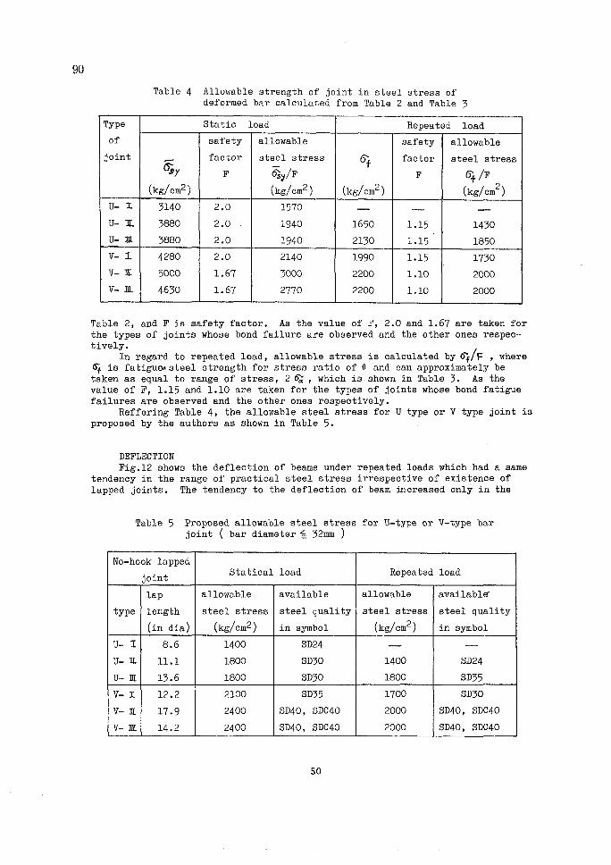
ALLOWABLE STEEL STRESSES Table 4 shows the allowablestrength of bar joint in steei stress ofdeformed bar. This table is calculatedas follows: In regard to statical load, allowa・-ble stress of deformed bar is calculatedby er/F , where E51), is steel stress at
yielding of beam, which is shown in
47
observed, and there- fore they affected considerably the strength of beam, apparent difference between yielding load and ultimate load of beam being searcely observed. ]iiurther- more, Mable 2 shows that in case of V type joint there existed a linear relationship between beam strength-in steel stress q7 and lap length of joint inclusive of diagonal parts of lapped bars as shown in Fig.8. This shows that the diagonal parts Qf bars of joint were effective to be taken as parts of lap length. Second, fatigue test results and the view of beams after failure were as shown in Table 3 and ?ig.9 respectively. Similarly as in ease of statical test the scarcely any effectand V--r joint were the case where the beam was always shown in Fig.10.and neglecting thehistory,eg-IV diagrams in Fig.11, where 6;stress and N is cycles this figure theof steel Gl at 2 million
ratio of O.25 wasbeam and shown in Table

L
88
a) Beam 4017 no Joint
b) Beam 4020 joint L-I
c) Beam 4025 joint U-1
sti
d) Beam 4027 joint U-1
e) Beam 4029 joint U-M
f) Beam 4051 joint v- r
lgs
g) Beam 4055
ec "igagv-
joint V- Z
llaglpt za.eg
vag.l2
h) Beam 4055 joint V-I
Fig.9 View of test beams after fatigue failure
48

89
Table 5 Fatigue beam test results
Joint Cyclesofrepeatedload(lo5)TestbeamNo.
b
Max.SteelStress6,L(kg/cm2)
Assumedfatiguesteelstrengthat2lo6cycles(S=O.25)
typelaplength
'(india)
ConcreteStrength
(kg/cm2) 2200 2600 5000 5400
g(kgcm2) rangeofstress2ea(kg/cm2)
4017 nojoint 382. 1000 395x 5080 2510
4020 L...if 50 409 1000 1000 247+ 2980 2250
4025
4027
4029
u-x
U-IU-N・
8.6
11.1
l5,6
585
455
548
.NX641000
1000
2sgN
IOOO-ee
508
''pt2200
2840
an1650
2150
4031
4035
4055
V--1
V-1
v-x
12.2
17.9
14.2
476
437
459
1000 1000-ce
249
970+
88gx'
2650
2940
2940
・1990
2200
2200
-es-
'fracture ofbond faSlure
deeinforcing bar of lapped joint
Aecg 60Ets so
g S 4o
ix 30
gt ,,
g. ,,
"S 6o
g ,,
ll' 4o
m es e 30ule ept
e 20 ,S' iO
(a)
S:)C 40, 2di16
nojoiftt
s : e.2s
eeearn 4017 N ..rs}i k!"./l.t"."".."ss':i-;f--.q..
Prbleieus test fesults "hsg・t.- la wby authors -la-l"
il
wa
10 2030 Number(b)
S0701oo iecK} soO 1(KX} mm
of repetition NtXtOS)
Xpt' 6o
St 5o
g,,
thee
pt e 3e-pt .
e g 2',
. MS 10
fg'be- 6o
Eks so
xX 4o
ge .30
gU 2eti
g lo
(ec)
SDC40,2e16U type joint
szaO.2S ・ Searn 402g,'U-tll
Ke t/t ' ' ' '
・・・
,S99r!,i402.7,U-lt .
2ts
Z2
IO
(ct
20 30
Number)・
50ro1oo 200
- -, of irePetltton
t /t
500 1wn mm・N {xto3)
SDC40,2e16Conventienal Eapped jeint
sse.2SBeam 4020,Lmlt
Xa × A
t
A-pt
,g
10
SOC 40,2di16V type joint
s=O.2S ' Boam40ssand403S,
, ' ' '..tr.>¥n k.ilg
eeam 4p31,v-1 ' ' '
,
"-e-
ts
6
2o3osonlou.2oosoelooo2ooo loNurnber of repetition NtxlOg )
Fig.Xl Fatigue test results,
49
20 30 S070vaO 200
Nurnber of repetitioft
tt
tt ・l// -6;;-,V diggrams
i; "
509 10co
N (x toa
'
2ooO
}
90
Table 4 Allowable strength of joint in steel stress of deformed bar calculated from Table 2 and Mable 5
Type Statio load Repeated load
of safety allowable safety allowable
joint..-..
crsrfactor
P
steelstressEis;y/F
8f factor
F
steelstress(sfr/F
(kg/em2) (kg/cm2) (kg/em2) (kg/cm2)
u-z 5140 2.0 1570 pa op ptU-an 3880 2.0 1940 1650 lo15 1430
U-pt 3880 2.0 1940 2150 l850
v-z 4280 2.0 2140 1990 1.15 1750
V-K 5000 1.67 5000 2200 1.10 2000
V-4M 4650 1.67 2770 2200 1.10 2000
Table 2, and F is safety factor. As the value of F, 2.0 and 1.67 are taken forthe types of joints whose bond failure are observed and the other ones respec-tiVellh regard to repeated load, anowable stress is calculated by 6i/F , where
(S; is fatigueAsteel strength for stress ratio of O and can approximately betaken as equal to range of stress, 2 C5}[, which is shown in Table 3. As thevalue of F, 1.15 and 1.IO are taken for the types of joints whose bond fatiguefailures are observed and the other ones respeetively. Reffering Table 4, the allowable steel stress for U type or V type joint isproposed by the authors as shown in Table 5. .
' DEFLECTION Fig.l2 shows the defZection of beams under repeated loads which had a sametendency in the range of praetical steel stress irrespective of existence oflapped joints. The tendency to the deflection of beam tincreased only in the
Table 5 Proposed allowable steel stress for U-type or V-type bar joint ( bar diameter 4. 52mrn )
No-hook lapped
jointStatical load Repeated load
lap allowable available allowable availabler
type length steelstress steelguality steeistress steeZquality(india) (kg/cm2) insymbol (kg/cm2) insymbol
u-z 8.6 1400 SD24 nt opU--U Zl.l l800 SD30 1400 SD24
U-ur 13.6 l800 SD30 l800 SD35
v-z 12.2 2100 SD55 1700 SD30
v-ll 17.9 2400 SD40,SDC40 2000 SD40,SDC40
v-m 14.2 2400 SD40,SDC40 2000 SD40,SDC40
50

(q) U type jaint.
le . ....tw""k de.FO .to....ts.e---g ts ....t・-ege・;;-pt
Z, Zkili$;pt.lilllgll--ll-i&rgge:ut:ut.lilllgl :ei :bei-'asi
ect'}2 :.r-T:.:.r.r.l,"-"i":ilop.,zai,62kg./"MM
o
(a) U type jolatyi
91
ptb
eE.mt
tw
s.w.
pt
tsuge
eti
ress
1di
ce A - N-06 / youl ------ ---e2r""'Dbe.".'.e
di・ec
-e・--ab:U"'lt
'"--."" lUagelk/22ng rvifv)a,i
A: r. 26 ' 1 , e:e 30 " S- ・l ,,,pmfisti.i 1..:.:,.-. gs-upmedipe-
tt"dw.paucimtas:= dw:tw=
10an30S0701C)O2oo6CraeC}ee O 10 2030 SOro100 200 Sca tC)IX} Number of repetitib'fi NtXtete} Numbee of repetitiofi NtXIOS}
(b>v type joint (to)Vtypee joint t・O to E -.imanm,voi.,ag.22kg/rv'di pa
o a lo 2e3c} so7oloQ 2oo soo lcKm lo 203e S07elee 200 5001000 Ntstftbec "f fepetitiem NtXIOS) Nufnber of repcatitiefi N{Xlae)
Fig.12Deflectionofbeamunder Fig.13Maximumcrackwidthinbeam repeated load under repeated loadrange below 10- cycle$ of repeated loading, but thereafter it kept balance up to
just before the fracture of the beam.
CRACKING States of eraekings of beams after fatigue failure were as shown in Fig.9.The variation of the maximum crack width with repetition of loading were asshown in Fig.l3. This shows that the remarkable increase of crack openings washarctly observed in beams with any type of lapped joint under repeated IQads,when the maximum stresses 6b were kept under practical stresses.
Conclusions !t is certified that the no-hook lapped joints of U type and V type withthe dimensions shown in Fig.7 can be applied to the allowable stresses shown inTable 5. The diagonal parts of bars of joints in case of V type are effectiveto be taken as parts of lap length. There exists a linear relationship betweenthe lap !ength of V type joint inclusive of diagonal parts of bars and thestaticaZ strength of beam as shown in Fig.8. The deflection and cracking be-haviors of beams having joints of U type and V type for deformed bars are stableunder repeated loads, when the maximum stresses are under praetical stresses.
51
92
(i)
(2)
(3)
References ,H.ICokomichi, M.Hayashi and K.Kitamura; On Precast Conerete Slab Bridges,Bulletin of Civil Engineering Research Institute of Hokkaido Development
H.¥okomichi and ¥.]]'ujita; On Special Types of Lapped Joints of Reinforce-
ments, CAJ Cement Gijitsu NenpoX, 1956 .H.Yokomichi, Y.Fujita and T.Nishibori; Fatigue Test of Reinforced Concret.eBeams using Deformed Bars, The 2nd Symposium on Deformed Bars, JSCEConcrete Library No.14, Dee. 1965
'
52


![[Type text] [Type text] [Type text] - Pedologija](https://static.fdocument.pub/doc/165x107/61686889d394e9041f6f6413/type-text-type-text-type-text-pedologija.jpg)


