Cascades of π-phase plates: a transparent diffractive focusing system
8
Cascades of -phase plates: a transparent diffractive focusing system Emmanuel Cagniot, 1, * Michael Fromager, 1 Thomas Godin, 1 Mohamed Traïche, 2 Nicolas Passilly, 3 Birgit Päivänranta, 3 and Kamel Ait-Ameur 1 1 Centre de recherche sur les Ions, les Matériaux et la Photonique, Unité Mixte de Recherche 6252, Commissariat à l’Énergie Atomique, Centre National de la Recherche Scientifique, École Nationale Supérieure d’Ingénieurs de Caen, Université de Caen, 6 boulevard Maréchal Juin, F-14050 Caen, France 2 Centre de Développement des Technologies Avancées, Division Milieux Ionisés et Lasers, P.O. Box 17 Baba-Hassan, DZ-16303 Algiers, Algeria 3 Department of Physics and Mathematics, University of Eastern Finland, P.O. Box 111, FI-80101 Joensuu, Finland * Corresponding author: [email protected] Received February 1, 2010; revised May 4, 2010; accepted May 19, 2010; posted May 25, 2010 (Doc. ID 123620); published June 18, 2010 Typically, refractive lenses are used to focus rays of light, but an alternative way can be found by exploiting diffraction of light. It is well known that cascades of hard-edge apertures are able to focus light but with the great drawback of absorption losses. In this paper, we demonstrate that replacing hard-edge apertures with -phase plates within a cascade greatly improves the focusing of collimated Gaussian beams. In addition, we propose a simple model to design this cascade, in particular to find the locations and the radii of the different optics once the focal length has been chosen. This model deduced from numerical simulation is useful for sizing cascades consisting of a high number of components and characterized by a strong focusing ability, without requiring a time-consuming optimization process. © 2010 Optical Society of America OCIS codes: 050.0050, 050.1380, 050.5080. 1. INTRODUCTION The refractive index of a material in the x-ray range is usually expressed as 1- , where =10 -7 to 10 -5 . As a consequence, it is difficult to manufacture a single refrac- tive lens of short focal length for x-rays since is very close to unity. It is worthwhile to recall that a focal length of one or two meters is considered short in the x-ray range. An alternative way to focus short wavelengths is to resort to diffraction instead of refraction. Fresnel [1–6] and Bragg–Fresnel zone plates [7,8] belong to the family of diffractive focusing systems. These optical devices ex- ploit diffraction, interferences, and Fresnel zones [9] to fo- cus wavelengths for which refractive lenses are difficult to manufacture. Cascades of hard-edge apertures, initially studied in a plane wave context [10–12], are other representatives of this family. Let us consider a collimated Gaussian beam (wavelength , beam waist w 0 ) normally incident onto a cascade of two circular hard-edge apertures along the op- tical axis. In [13], the authors demonstrate numerically and experimentally a multifocal diffractive focusing effect for the following conditions: a 1 2 / L 1 =1, a 1 a 2 and a 2 2 / L 2 =2p +1, where p is a natural integer and a 1 and a 2 are the radii of the first and the second aperture, re- spectively, L 1 is the distance between the two apertures, and L 2 is the distance between the second aperture and the focal plane. This effect is optimal for p =0. An expla- nation is found when investigating the phase of the dif- fracted field behind the first and the second aperture. Let N 2p+1 be an odd Fresnel number and I f / I 0 the axial inten- sity enhancement factor, where I f and I 0 are the axial in- tensities of the diffracted field and of the incident beam, respectively. In [14], the authors demonstrate that in both cases, the diffracted field is convergent (focusing) from N 2p+2 to N 2p+1 , then divergent (defocusing) from N 2p+1 to N 2p , and so on. Moreover, the quality of the factor I f / I 0 is governed by the beam truncation ratio = a 1 / w 0 and the aperture radius ratio = a 2 / a 1 . The lower the and , the greater the I f / I 0 . For =95% and =40%, we achieve I f / I 0 6, while the energy efficiency of the diffractive fo- cusing of a Gaussian beam is demonstrated to be as high as 70% [13]. For = = 10% we can achieve I f / I 0 15 but at the cost of significant absorption losses. Note that the width of the beam waist w 0 must be taken into account in order to derive realistic values for a 2 and L 2 . The diffrac- tive focusing of De Broglie matter waves is investigated in [15,16]. In this study, we propose to replace hard-edge aper- tures with phase plates (transparent optics generating a phase shift in their central part thanks to a circular sur- face relief) in order to design cascades made of a high number of components and characterized by a strong fo- cusing ability. Since the near-field properties of a Gauss- ian beam diffracted through a hard-edge aperture and through a phase plate are very similar [17] and Gaussian beams are diffracted through phase plates without aper- turing losses, we can reasonably expect that cascades of phase plates should focus collimated Gaussian beams in a more efficient way. In this paper, we demonstrate the rel- evance of this assumption and more specifically show to be the optimal phase shift. Moreover, we demonstrate that for a chosen distance between the focal plane and the Cagniot et al. Vol. 27, No. 7/July 2010/J. Opt. Soc. Am. A 1647 1084-7529/10/071647-8/$15.00 © 2010 Optical Society of America
Transcript of Cascades of π-phase plates: a transparent diffractive focusing system

1Tuctcorraopcm
pt(ctafaasatnfNs
Cagniot et al. Vol. 27, No. 7 /July 2010 /J. Opt. Soc. Am. A 1647
Cascades of �-phase plates: a transparentdiffractive focusing system
Emmanuel Cagniot,1,* Michael Fromager,1 Thomas Godin,1 Mohamed Traïche,2 Nicolas Passilly,3 Birgit Päivänranta,3
and Kamel Ait-Ameur1
1Centre de recherche sur les Ions, les Matériaux et la Photonique, Unité Mixte de Recherche 6252,Commissariat à l’Énergie Atomique, Centre National de la Recherche Scientifique, École Nationale Supérieure
d’Ingénieurs de Caen, Université de Caen, 6 boulevard Maréchal Juin, F-14050 Caen, France2Centre de Développement des Technologies Avancées, Division Milieux Ionisés et Lasers, P.O. Box 17 Baba-Hassan,
DZ-16303 Algiers, Algeria3Department of Physics and Mathematics, University of Eastern Finland, P.O. Box 111, FI-80101 Joensuu, Finland
*Corresponding author: [email protected]
Received February 1, 2010; revised May 4, 2010; accepted May 19, 2010;posted May 25, 2010 (Doc. ID 123620); published June 18, 2010
Typically, refractive lenses are used to focus rays of light, but an alternative way can be found by exploitingdiffraction of light. It is well known that cascades of hard-edge apertures are able to focus light but with thegreat drawback of absorption losses. In this paper, we demonstrate that replacing hard-edge apertures with�-phase plates within a cascade greatly improves the focusing of collimated Gaussian beams. In addition, wepropose a simple model to design this cascade, in particular to find the locations and the radii of the differentoptics once the focal length has been chosen. This model deduced from numerical simulation is useful for sizingcascades consisting of a high number of components and characterized by a strong focusing ability, withoutrequiring a time-consuming optimization process. © 2010 Optical Society of America
OCIS codes: 050.0050, 050.1380, 050.5080.
trcNNgagIcaawot[
tpfncitbtpmebt
. INTRODUCTIONhe refractive index of a material in the x-ray range issually expressed as ��1−�, where �=10−7 to 10−5. As aonsequence, it is difficult to manufacture a single refrac-ive lens of short focal length for x-rays since � is verylose to unity. It is worthwhile to recall that a focal lengthf one or two meters is considered short in the x-rayange. An alternative way to focus short wavelengths is toesort to diffraction instead of refraction. Fresnel [1–6]nd Bragg–Fresnel zone plates [7,8] belong to the familyf diffractive focusing systems. These optical devices ex-loit diffraction, interferences, and Fresnel zones [9] to fo-us wavelengths for which refractive lenses are difficult toanufacture.Cascades of hard-edge apertures, initially studied in a
lane wave context [10–12], are other representatives ofhis family. Let us consider a collimated Gaussian beamwavelength �, beam waist w0) normally incident onto aascade of two circular hard-edge apertures along the op-ical axis. In [13], the authors demonstrate numericallynd experimentally a multifocal diffractive focusing effector the following conditions: a1
2 / ��L1�=1, a1�a2 and
22/ ��L2�=2p+1, where p is a natural integer and a1 and2 are the radii of the first and the second aperture, re-pectively, L1 is the distance between the two apertures,nd L2 is the distance between the second aperture andhe focal plane. This effect is optimal for p=0. An expla-ation is found when investigating the phase of the dif-racted field behind the first and the second aperture. Let
2p+1 be an odd Fresnel number and If /I0 the axial inten-ity enhancement factor, where I and I are the axial in-
f 01084-7529/10/071647-8/$15.00 © 2
ensities of the diffracted field and of the incident beam,espectively. In [14], the authors demonstrate that in bothases, the diffracted field is convergent (focusing) from2p+2 to N2p+1, then divergent (defocusing) from N2p+1 to2p, and so on. Moreover, the quality of the factor If /I0 is
overned by the beam truncation ratio �=a1 /w0 and theperture radius ratio �=a2 /a1. The lower the � and �, thereater the If /I0. For �=95% and �=40%, we achievef /I0�6, while the energy efficiency of the diffractive fo-using of a Gaussian beam is demonstrated to be as highs 70% [13]. For �=�=10% we can achieve If /I0�15 butt the cost of significant absorption losses. Note that theidth of the beam waist w0 must be taken into account inrder to derive realistic values for a2 and L2. The diffrac-ive focusing of De Broglie matter waves is investigated in15,16].
In this study, we propose to replace hard-edge aper-ures with phase plates (transparent optics generating ahase shift in their central part thanks to a circular sur-ace relief) in order to design cascades made of a highumber of components and characterized by a strong fo-using ability. Since the near-field properties of a Gauss-an beam diffracted through a hard-edge aperture andhrough a phase plate are very similar [17] and Gaussianeams are diffracted through phase plates without aper-uring losses, we can reasonably expect that cascades ofhase plates should focus collimated Gaussian beams in aore efficient way. In this paper, we demonstrate the rel-
vance of this assumption and more specifically show � toe the optimal phase shift. Moreover, we demonstratehat for a chosen distance between the focal plane and the
010 Optical Society of America

lco
tGmrmpsctpiag
2Ltp
wpp
G
w
tR
w
APcppmpBocmfbkpl
Tf
w
a
w
1648 J. Opt. Soc. Am. A/Vol. 27, No. 7 /July 2010 Cagniot et al.
ast optic of the cascade, we can easily determine the lo-ation and the radius of any additional �-phase plate inrder to increase the focusing effect.
This paper is structured as follows. Section 2 presentshe modeling of a cascade of phase plates by using theaussian beam expansion method (GBEM) and its opti-ization by the adaptive simulated annealing (ASA) algo-
ithm. Section 3 reports optimization results for a colli-ated Gaussian beam focused by cascades of up to four
hase plates. These results identify � as the ideal phasehift. Moreover, they suggest a simple model for sizing aascade of �-phase plates depending on the beam waist ofhe incident beam and the distance between the focallane and the last phase plate of the cascade. This models presented in Section 4 and validated both numericallynd experimentally in Section 5. Finally, the conclusion isiven in Section 6.
. MODELING AND OPTIMIZATIONet us consider a cascade of phase plates shown in Fig. 1hat consists of m AiBiCiDi free propagators and m phaselates each with a given transmittance function
��
ai� = �exp�ji�, 0 � � ai,
1, � ai,� �1�
here ai and i� �0,�� represent the radius and thehase shift of the ith phase plate, respectively. The firsthase plate is located at plane z=0.The cascade is illuminated by a normally incident
aussian beam having electric field of the form
��,z� = �z�exp−2
w�z�2exp− jk2
2R�z� , �2�
here
�z� =�2
�
1
w�z�exp�j��z��exp�− jk�z − z0��. �3�
Here, z0 is the location of the beam waist w0 and k ishe wave number. The waist w�z�, the radius of curvature�z�, and the Gouy phase shift ��z� have the forms
w�z� = w01 + � z − z0
zR�21/2
, �4�
R�z� = �z − z0�1 + � zR
z − z0�2 , �5�
C1 Dm
A1 B1
2 a1
C2 D2
A2 B2
2 a2
Cm
Am Bm
2 am
Dm
z = 0z
... ... ...
Fig. 1. Cascade of m phase plates.
��z� = arctan� z − z0
zR� , �6�
here zR=�w02 /� is the Rayleigh range of the beam.
. Modelingropagators based on fast Fourier transform (FFT) are aommon technique for modeling cascades of optical com-onents, but special care must be taken with the sam-ling of diffracted fields in order to avoid aliasing. Forulti-apertured ABCD optical systems [18], a more so-
histicated technique consists in using the GBEM [19].y expanding the circ function into an approximate sumf complex Gaussian functions having (amplitude) coeffi-ients obtained directly by optimization computation, thisethod allows us to transform the Fresnel–Kirchhoff dif-
raction integral containing a p-order Laguerre–Gaussianeam into a finite sum of Hankel transforms havingnown analytical expressions. From a computationaloint of view, the main interest of such a transformationies in an analytical expression of the diffracted field.
Let us model the cascade of Fig. 1 using the GBEM.he diffracted field at plane z=B1 is given by the Collins
ormula [20],
E1�r,z� =jk
B1exp�− jkz�exp�−
jkD1
2B1r2�
� 0
+�
��
a1���,0�exp�−
jkA1
2B12�J0� k
B1r�d
= �0�jk
B1exp�− jkz�exp�−
jkD1
2B1r2�
� 0
+�
��
a1�exp�− Q�1�2�J0� k
B1r�d, �7�
here
Q�1� =1
w�0�2 + jk
2A1
B1+
1
R�0� , �8�
nd J0 is the zero-order Bessel function of the first kind.Substituting Eq. (1) into Eq. (7) leads to
E1�r,z� = �0�jk
B1exp�− jkz�exp�−
jkD1
2B1r2�
���exp�j1� − 1� 0
a1
exp�− Q�1�2�J0� k
B1r�d
+ 0
+�
exp�− Q�1�2�J0� k
B1r�d� . �9�
By introducing the circ function,
circ�
a� = �1, 0 � � a,
0, � a, � �10�
e can represent Eq. (9) in the form

c
waf
w
uG
Rm
wfi
r=
w
t+
w
BOpdefHfponilsw
Cagniot et al. Vol. 27, No. 7 /July 2010 /J. Opt. Soc. Am. A 1649
E1�r,z� = �0�jk
B1exp�− jkz�exp�−
jkD1
2B1r2�
���exp�j1� − 1� 0
+�
circ�
a1�
�exp�− Q�1�2�J0� k
B1r�d
+ 0
+�
exp�− Q�1�2�J0� k
B1r�d� . �11�
By further expanding the circ function onto a set of Nomplex Gaussian functions,
circ�
a� � �n=0
N−1
Fn exp�−Gn
a2 2� , �12�
here complex constants Fn and Gn denote the expansionnd Gaussian coefficients, respectively, Eq. (11) can be re-ormulated as
E1�r,z� � �0�jk
B1exp�− jkz�exp�−
jkD1
2B1r2�
���exp�j1� − 1� �n1=0
N−1 Fn1
� 0
+�
exp�− Qn1�1�2�J0� k
B1r�d
+ 0
+�
exp�− Q�1�2�J0� k
B1r�d� , �13�
here
Qn1�1� = Q�1� +
Gn1
a12 . �14�
In order to derive a homogeneous form for Eq. (13), lets define S�1�, the set of N+1 pairs of coefficients (Fn1
�1�,
n1�1�). so that
�∀n1 � N, �Fn1
�1�,Gn1�1�� = �Fn1,Gn1�,
�FN�1�,GN
�1�� = � 1
exp�j1� − 1,0� .� �15�
Now, we can transform Eq. (14) into
∀n1 � N, Qn1�1� = Q�1� +
Gn1�1�
a12 . �16�
Since Re�Q�1���0 and Re�Gn1��0, we also end up withe�Qn1
�1���0. Therefore, after recalling the integral for-ula
0
+�
exp�− pt2�J0�bt�tdt =1
2pexp�−
b2
4p�, Re�p� � 0,
�17�
e can finally derive the analytical form for the diffractedeld at plane z=B :
1E1�r,z� � �0�jk
B1exp�− jkz�exp�−
jkD1
2B1r2��exp�j1� − 1�
� �n1=0
N Fn1�1�
2Qn1�1�
exp�−k2
4Qn1�1�B1
2r2� . �18�
Performing the next integral calculation step, we de-ive the analytical form of the diffracted field at plane zB1+B2:
E2�r,z� � �0�jk
B1
jk
B2exp�− jkz�exp�−
jkD2
2B2r2��exp�j1� − 1�
��exp�j2� − 1� � �n1=0
N Fn1�1�
2Qn1�1� �
n2=0
N Fn2�2�
2Qn2�2�
�exp�−k2
4Qn2�2�B2
2r2� , �19�
here
Qn2�2� =
k2
4Qn1�1�B1
2+ j
k
2D1
B1+
A2
B2 +
Gn2�2�
a22 . �20�
Finally, after m integral calculation steps, we derivehe analytical form of the diffracted field at plane z=B1B2+ ¯+Bm:
Em�r,z� � �0�jk
B1
jk
B2¯
jk
Bmexp�− jkz�exp�−
jkDm
2Bmr2�
��exp�j1� − 1��exp�j2� − 1� ¯ �exp�jm� − 1�
� �n1=0
N Fn1�1�
2Qn1�1� �
n2=0
N Fn2�2�
2Qn2�2�
¯ �nm=0
N Fnm�m�
2Qnm�m�
�exp�−k2
4Qnm�m�Bm
2r2� , �21�
here
Qnm�m� =
k2
4Qnm−1�m−1�Bm−1
2+ j
k
2Dm−1
Bm−1+
Am
Bm +
Gnm�m�
am2 . �22�
. Optimizationptimizing the diffractive focusing effect of a cascade ofhase plates involves solving a 3m variable problem (ra-ius ai, phase shift i, and propagation distance Bi forach phase plate). This can be accomplished using power-ul stochastic methods such as the ASA algorithm [21].owever, when using the GBEM, the incident beam dif-
racted from the first phase plate is expanded onto N ex-ansion functions that are further diffracted from the sec-nd phase plate and so on, which increases the totalumber of diffracted waves to Nm. Therefore, by consider-
ng that each set of expansion coefficients requires ateast ten terms [19], numerical simulation of a cascade ofix phase plates would involve one million diffractedaves, which is unreasonable in terms of computation
tut
3PACHC12chtaag−o-sb
BWpm
oRozaSt
�Ic
s(twcttolibt
pfat
CTccitttItrFppl
1650 J. Opt. Soc. Am. A/Vol. 27, No. 7 /July 2010 Cagniot et al.
ime within an optimization process. As a consequence,sing the GBEM requires optimizing cascades of lesshan six phase plates.
. RESULTS OF THE OPTIMIZATIONROCESS. Hardware and Software Settingsomputations have been performed on a Hewlett PackardDX X18–1250EF Premium Notebook PC (Intel 64-bitore 2 Duo P8600 2.40 GHz, 4 GBytes of DDR3 memoryGHz, 3 GBytes of L2 cache) running Linux kernel
.6.32.10 (Fedora distribution–“Constantine”). The appli-ation is written in C�� and makes intensive use of in-eritance and polymorphism. It requires the GNU Scien-ific Library 1.13 (GSL–special mathematical functions)nd the ASA package 26.35 (skeleton of an adaptive SAlgorithm written in C), and it is compiled with the GNU�� compiler 4.4.3 and the following optimizations:march=native (instruction set of the host processornly), -funroll-loops (loop unrolling), -msse2msse3 -mssse3 -msse4 (all available streaming in-truction sets for double-precision floating-point num-ers) and -03 (level 3 optimizations).
. Numerical Settingse restrict our study to cascades of up to four phase
lates illuminated from a normal incidence with a colli-ated Gaussian beam (�=808 nm, w0=1.4 mm).Settings chosen for the ASA algorithm are the default
nes. The cost function to be maximized is the factor If /I0.adii ai, phase shifts i, and propagation distances Bi areptimized as continuous variables. We apply the optimi-ation process to several test cases by requiring each timeconstraint on the minimum propagation distance Bmin.
ince w0��, the maximum propagation distance is set tohe Rayleigh range of the beam. Phase shifts i range in
Table 1.
# a (mm) (rad.) B (mm)
1 0.12 3.14 18.7
1 0.59 3.14 86.92 0.37 3.14 55.8
1 0.54 3.14 3942 0.08 3.14 10
1 0.87 3.14 6732 0.42 3.14 1933 0.08 3.14 10
1 1.32 3.13 4052 0.9 3.14 2043 0.57 3.14 744 0.38 3.14 60.1
1 1.08 3.13 91.62 0.72 3.13 4883 0.3 3.14 614 0.09 3.13 10
0,��, while radii ai in millimeters range in [0.075, 4.5].nitial values for ai, i and Bi (starting configuration) arehosen randomly.
Since the optimization process seems very sensitive totarting configurations, we run it ten times per cascadefrom one to four phase plates) with the re-annealing op-ion of the ASA algorithm enabled and ten other timesith this option disabled. The re-annealing option avoids
onvergence toward local maxima. Therefore, enablinghis option often leads to high-intensity enhancement fac-ors to the detriment (seemingly) of specific arrangementsf phases plates. Conversely, disabling this option ofteneads to a specific arrangement of interest but lowest-ntensity enhancement factors. This is the reason whyoth results will be presented (except when they are iden-ical).
The circ function is expanded onto a set of N=25 com-lex Gaussian functions with expansion coefficients takenrom Table 3 of [22]. Since this set is the largest one, it islso the most accurate at the expense of computationime.
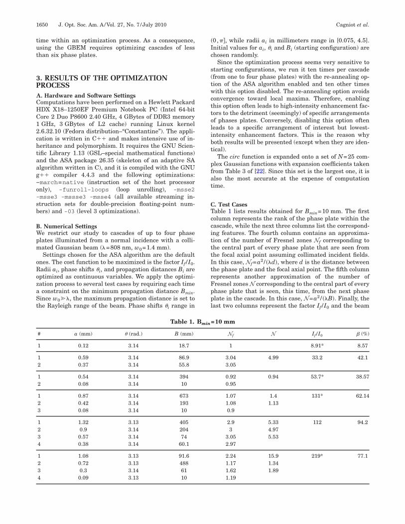
. Test Casesable 1 lists results obtained for Bmin=10 mm. The firstolumn represents the rank of the phase plate within theascade, while the next three columns list the correspond-ng features. The fourth column contains an approxima-ion of the number of Fresnel zones Nf corresponding tohe central part of every phase plate that are seen fromhe focal axial point assuming collimated incident fields.n this case, Nf=a2 / ��d�, where d is the distance betweenhe phase plate and the focal axial point. The fifth columnepresents another approximation of the number ofresnel zones N corresponding to the central part of everyhase plate that is seen, this time, from the next phaselate in the cascade. In this case, N=a2 / ��B�. Finally, theast two columns represent the factor If /I0 and the beam
=10 mm
Nf N If /I0 � (%)
1 8.91* 8.57
3.04 4.99 33.2 42.13.05
0.92 0.94 53.7* 38.570.95
1.07 1.4 131* 62.141.08 1.130.9
2.9 5.33 112 94.23 4.97
3.05 5.532.97
2.24 15.9 219* 77.11.17 1.341.62 1.891.19
Bmin

tea
aeatltfbaIea(ft�
asc
(ss
DTshiMa(�d
Cagniot et al. Vol. 27, No. 7 /July 2010 /J. Opt. Soc. Am. A 1651
runcation ratio �=a1 /w0 (by analogy with hard-edge ap-rtures), respectively. Factors If /I0 calculated with the re-nnealing option enabled are denoted by an asterisk.Despite the fact that these results are provided through
n optimization process (hence, they are inaccurate), theyxhibit several interesting features. First, the factor If /I0chieved by a cascade of two phase plates is at least aboutwo times larger ��33� and at most about three timesarger ��53� than the best result achieved by a cascade ofwo hard-edge apertures ��15�. In addition, a cascade ofour phase plates increases the axial intensity of the beamy a factor close to 220. The most interesting results prob-bly concern phase shifts i and propagation distances Bi.ndeed, the phase shift selected for every phase plate isxtremely close to �. Moreover, in most cases, Nf and Nre close to pairs of odd integers, either (Nf�1, N�1) orNf�3, N�5). However, it seems that for a cascade ofour phase plates the re-annealing option failed to makehe optimization process converge to the pair (Nf�1, N1).
Table 2.
# a (mm) (rad.) B (mm)
1 0.2 3.14 52.8
1 0.53 3.14 63.92 0.35 3.14 50
1 0.79 3.14 8652 0.19 3.14 50
1 0.88 3.14 2182 0.52 3.14 57.83 0.36 3.13 54.1
1 1.23 3.14 11302 0.83 3.12 53.33 0.55 3.14 2404 0.22 3.14 50
Table 3. Bmin
# a (mm) B (mm)
1 0.1 12.4
1 0.56 4112 0.08 10
1 0.9 7122 0.39 1853 0.08 10
1 0.58 97.82 0.37 36.73 0.25 17.24 0.14 10
1 0.99 79.12 0.65 4093 0.28 53.94 0.09 10
Table 2 lists results obtained for Bmin=50 mm. Theyre similar to those of the previous test case. However, iteems that increasing Bmin makes the factor If /I0 de-rease.
Finally, Table 3 lists results obtained for Bmin=10 mmfirst test case) and =�. We can see that fixing the phasehift to � does not significantly improve the results pre-ented in Table 1.
. Discussionhe convergence toward � as the ideal phase shift is noturprising. Indeed, in [17], the authors demonstrate thatard-edge apertures and �-phase plates behave similarly
n the near-field region when diffracting Gaussian beams.ore precisely, in both cases, maxima (minima) of the
xial intensity occur when Fresnel numbers are oddeven) but maxima (minima) are higher (lower) for-phase plates than for hard-edge apertures. Hence, theiffractive focusing effect is stronger with �-phase plates
=50 mm
Nf N If /I0 � (%)
1 8.75* 14.2
3.07 5.48 33.8 383.07
0.85 0.9 34.2* 56.40.91
2.94 4.45 75.4* 62.83.07 5.943.05
1.28 1.67 92.3* 882.52 16.21.59 39.61.24
m and �=�
N If /I0 � (%)
8.94* 7.16
0.94 53.7* 40.1
1.41 125* 64.31.02
4.26 157 41.44.624.53
15.4 229* 70.81.311.88
Bmin
=10 m
Nf
1
0.920.96
1.110.960.89
2.572.652.872.43
2.21.131.591.15

titp
tspdIea
(ct
w
wo
pmcqNlt
w
atcetf
db
whmaop
4OIcptcb
ntcca
o
s
t
tH
t
dq
p
wt
f
1652 J. Opt. Soc. Am. A/Vol. 27, No. 7 /July 2010 Cagniot et al.
han with hard-edge apertures. However, since this results demonstrated for a single �-phase plate, and because ofhe beam-shaping ability of phase plates, an optimizationrocess was necessary to confirm it.Fresnel numbers Nf and N provide valuable informa-
ion about the arrangement of �-phase plates. Indeed,ince every optic of the cascade is seen from the focal axialoint at Nf, each additional component satisfying the con-ition a2=�dNf contributes to the increase of the factorf /I0. However, this contribution is optimal if, and only if,ach component of the cascade is seen from the next onet N.Results in Tables 1 and 2 reveal two possible pairs:
Nf�1, N�1) and (Nf�3, N�5). Let us consider a cas-ade of two phase plates governed by the following equa-ions:
a22 = �NfB2, �23�
a12 = �Nf�B1 + B2�, �24�
a12 = �NB1, �25�
here B2=Bmin.Substituting Eqs. (23) and (25) into Eq. (24) leads to
1 =Nf
N+ �2, �26�
here �=a2 /a1 is the phase-plate-radius ratio (by anal-gy with hard-edge apertures).
Since the pair (Nf=1, N=1) contradicts Eq. (26), theair (Nf=1, N=1+�), where � is a small positive quantity,ust be chosen such that each additional component in-
reases the focusing effect of the cascade. As a conse-uence, the radius a1 must be chosen such that a1�a2.ow, if the cascade contains m phase plates, then the fol-
owing conditions must be satisfied in order to maximizehe focusing effect:
a1 � a2 � ¯ � am, �27�
� � 1, �28�
here �=a1 /w0.From Eqs. (27) and (28) it is clear that m is necessarilysmall number. As an illustration, if one chose N=1.1,
he maximum number m would be m=3 for the first testase (Table 1) and m=2 for the second one (Table 2). Thisxplains why, in both cases, the re-annealing option madehe ASA algorithm converge to a disorganized structure ofour phase plates.
Now, let us investigate the pair (Nf=3, N=5). Since itoes not contradict Eq. (26), the strict condition definedy Eq. (27) is replaced by the relaxed condition
a1 � a2 � ¯ � am, �29�
hich makes m greater than for (Nf=1, N=1+�) andence improves the focusing effect. As an illustration, theaximum number m would be m=5 for the first test case
nd m=4 for the second one. In the next section, we dem-nstrate that (Nf=3, N=5) maximizes the number of com-onents and therefore the focusing effect.
. SIMPLE MODEL FOR SIZING A CASCADEF �-PHASE PLATES
n this section, we propose a simple model for sizing a cas-ade of �-phase plates once the distance between the focallane and the last �-phase plate is set. In the following,his distance will be referred to as the focal length f of theascade. We base our model on the fact that Fresnel num-ers Nf and N are close to odd integers.Let us consider a cascade of m �-phase plates that are
umbered from zero in the reverse order; i.e., k=m−1 ishe rank of the first �-phase plate illuminated by the in-ident beam while k=0 is the rank of the last one. The fo-al plane and the last �-phase plate are located at z=0nd z0= f, respectively.According to our assumption, a focusing effect can be
btained with optics having a radius
ak = �Nf�zk�1/2. �30�
To ensure an optimal focusing effect, N must be chosenuch that N�Nf. Therefore, since
ak = �Nf�zk�1/2 = �N��zk − zk−1��1/2, k � 0, �31�
he optimal location of every �-phase plate is
zk = � NN − Nf
�k
f, k � 0. �32�
Results shown in Tables 1 and 2 suggest that propaga-ion distances Bk must be selected such that Bk+1�Bk.ence, z1−z0=z1− f� f and therefore we obtain
NN − Nf
� 2. �33�
As a consequence, the optimal range for N has the limi-ation of
Nf � N � 2Nf. �34�
These results also suggest that every �-phase plate ra-ius must be chosen in a way such that ak�w0. Conse-uently, we must also have
Nf�zk � w02. �35�
Further, by substituting Eq. (32) into Eq. (35) we obtain
� NN − Nf
�k
�w0
2
Nf�f. �36�
Finally, we derive the maximum number of �-phaselates of the cascade,
m̄ = � ln� w02
Nf�f�ln� N
N − Nf� �, �37�
here the delimiters denote the ceiling function and ln ishe natural logarithm.
Increasing the number of �-phase plates increases theocusing power, thus making it desirable to maximize m̄.

FpNwdrwficihmal
tpce
5AFS4stt
fweNN
fn
bwbi
tfmrctuttac�it
BTllctif(�piwp=a=�=
dwp
Cagniot et al. Vol. 27, No. 7 /July 2010 /J. Opt. Soc. Am. A 1653
or this purpose, the ratio N / �N−Nf� must be as small asossible, i.e., close to 2 [see Eq. (33)], implying that Nf and
are consecutive odd integers. Only Nf=3 associatedith N=5 is allowed since the pair (Nf=1, N=3) contra-icts Eq. (34). As a consequence, since the natural loga-ithm grows slowly to positive infinity and ln�3/2��0.4,e must have w0
2 / �Nf�f��1. This condition can be satis-ed if, and only if, f or � are short. On the one hand, wean expect that short focal lengths induce experimentalmplementation problems. On the other hand, achievingigh focusing efficiencies for short-wavelength beamsakes this system more appropriate for focusing x-rays,
lthough the model remains valid as well for longer wave-engths.
Note that because of its transparency, the magnitude ofhe focal spot width achieved by a cascade of �-phaselates is obtained by dividing the width of the incidentollimated beam by the square root of the axial intensitynhancement factor If /I0.
. VALIDATION OF THE MODEL. Numericalirst, we apply our model to the test case mentioned inection 3 in which Bmin= f=10 mm (Tables 1 and 3). Tablelists the corresponding results. The four columns repre-
ent the number of �-phase plates m, the whole length ofhe cascade L=zm−1, the factor If /I0, and the beam-runcation ratio �=am−1/w0, respectively.
By comparing Tables 1 and 4, we can see that the bestactors If /I0 are achieved by the pair (Nf=1, N=1+�)hile the condition defined by Eq. (28) is satisfied. How-ver, since this limit is reached promptly, the pair (Nf=3,=5) have the advantage over the pair (Nf=1, N=1+�).ote that the results in Table 4 demonstrate that the dif-
Table 4. Numerical Validation of Our Model withthe First Test Case Mentioned in Section 3
„Bmin=f=10 mm…
m L (mm) If /I0 � (%)
1 10 8.88 11.12 25 40 17.63 62.5 109 27.84 156 207 445 391 275 69.5
Table 5. Numerical Validation of Our Mode
m
�=808 nm
L (mm) If /I0 L (
1 50 7.72 125 28.1 13 312.5 53.9 314 78567
aIn the case of the x-ray wavelength, the cascade can contain up to twelve �-ph
ractive focusing effect of a cascade of �-phase plates isot linear with respect to the number of components.Second, we consider a collimated Gaussian beam with a
eam waist w0=1 mm and a focal length f=50 mm. Threeavelengths are tested: 808 nm (red), 405 nm (violetlue), and 1.54 Å (x-ray). Table 5 presents the correspond-ng results.
As expected, the smaller the wavelength, the higherhe possible maximum number of �-phase plates and theactor If /I0. In the case of the x-ray wavelength, the maxi-
um number of �-phase plates is twelve. However, as al-eady pointed out in Section 2, computation time in-reases dramatically for numbers of phase plates suchhat m�6. Consequently, we have performed simulationsp to seven �-phase plates. It is important to mentionhat when a small error is introduced either in the loca-ion of a �-phase plate or in its radius, the result is virtu-lly unaffected. This numerical observation has beenhecked experimentally; i.e., a rough positioning of the-phase plates is sufficient to reach the predicted focus-
ng. Consequently, the experimental implementation ofhe setup should be facilitated.
. Experimentalhe experimental validation was performed using the fol-
owing optical layout. The beam is provided by a 100 mWaser diode (Lumics LU0808M100) operating at 808 nmoupled to a single-mode optical fiber that is itself coupledo a fiber collimation package (Thorlabs, Inc.). The result-ng collimated beam �w0=1.4 mm� with a beam qualityactor of 1.1, measured with a M2−200 beam scannerSpiricon, Inc.), is diffracted through a cascade of two-phase plates manufactured by a standard lithographyrocess [23]. A neutral density filter whose optical densitys 7 is used to avoid saturation of the CCD camera onhich the diffraction pattern is monitored. Because of ex-erimental constraints, the focal length is chosen to be f70 mm. The cascade features predicted by our model are0=0.41 mm ��=46.5%�, z0=70 mm, a1=0.65 mm, z1175 mm, and If /I0=31.4. Experimentally, we used-phase plates with radii equal to a0=0.42 mm and a10.65 mm.The diffraction pattern (normalized intensity) pre-
icted by our model and the experimental one obtainedith the CCD camera are compared in Fig. 2. There ap-ears to be a very good match. Nevertheless, an obvious
arious Wavelengths (w0=1 mm, f=50 mm)a
=405 nm �=1.54 Å
If /I0 L (mm) If /I0
8.33 50 9.0334.1 125 41.678.4 312.5 118.7113.4 781.2 246.5
1953.1 373.14882.8 474.212207 686.5
s.
l for V
�
mm)
50252.51.2
ase plate

lfw
pie
6Ptpliti
�isoptbfobnfds
R
1
1
1
1
1
1
1
1
1
1
2
2
2
2
1654 J. Opt. Soc. Am. A/Vol. 27, No. 7 /July 2010 Cagniot et al.
imitation should be pointed out: the M2 beam qualityactor has increased at the output of the cascade since itas measured to be M2�4.It should be noted that such cross-checkings have been
erformed with all available pairs of �-phase plates sat-sfying the requirements established in Section 4, and anxcellent agreement was found.
. CONCLUSIONhase plates are devices, such as hard-edge apertures,hat are able to focus laser beams. However, since phaselates are made of transparent materials, they do notead to aperturing losses. Thus, a cascade of phase platess expected to achieve results much superior to those ob-ained with a cascade of hard-edge apertures when focus-ng collimated Gaussian beams.
In this paper, we have demonstrated that a cascade of-phase plates has the ability to focus collimated Gauss-
an beams. In addition, we propose a simple model to de-ign this cascade by predicting the radius and the locationf every �-phase plate as well as the maximum number ofhase plates. Moreover, we showed with this model thathe smaller the wavelength, the higher the focusing effectecause of the higher number of optics allowed. There-ore, x-ray sources could be ideal candidates for cascadesf �-phase plates made of transparent materials such aseryllium windows. This model has been validated bothumerically and experimentally. In addition, we have
ound that the location and the radius of the phase plateso not have to be very accurately defined. This propertyhould facilitate the experimental implementation.
EFERENCES1. A. V. Baez, “Fresnel zone plate for optical image formation
using extreme ultraviolet and soft x radiation,” J. Opt. Soc.Am. 51, 405–412 (1961).
2. G. Boivin, “Use of a fresnel zone plate for optical image in-
0
0.2
0.4
0.6
0.8
1
-1 -0.5 0 0.5 1
Nor
mal
ized
inte
nsity
r (mm)
ModelExperimental
Fig. 2. Experimental–numerical comparison.
formation with short wavelength radiations,” Appl. Opt. 16,1070–1073 (1977).
3. Y. A. Basov, D. V. Roshchupkin, and A. E. Yakshin, “Graz-ing incidence phase fresnel zone plate for x-ray focusing,”Opt. Commun. 109, 324–327 (1994).
4. V. Aristov, A. Isoyan, V. Kohn, A. Kuyumchyan, E. Shula-kov, A. Snigirev, and I. Snigireva, “Study of optical proper-ties of x-ray system based on two zone plates,” Nucl. In-strum. Methods Phys. Res. A 575, 238–241 (2007).
5. R. G. Mote, S. F. Yu, B. K. Ng, W. Zhou, and S. P. Lau,“Near-field focusing properties of zone plates in visibleregime—new insights,” Opt. Express 16, 9554–9564 (2008).
6. J. Alda, J. M. Rico-García, F. J. Salgado-Remacha, and L.M. Sanchez-Brea, “Diffractive performance of squareFresnel zone plates,” Opt. Commun. 282, 3402–3407 (2009).
7. V. V. Aristov, Y. A. Basov, S. V. Redkin, A. A. Snigirev, andV. A. Yunkin, “Bragg zone plates for hard x-ray focusing,”Nucl. Instrum. Methods Phys. Res. A 261, 72–74 (1987).
8. M. Idir, A. Mirone, G. Soullie, P. Guerin, F. Ladan, and P.Dhez, “2d focusing with an off-axis elliptical Bragg-Fresnelmultilayer lens and application to x-ray imaging,” Opt.Commun. 119, 633–642 (1995).
9. N. Sergienko, V. Dhayalan, and J. J. Stamnes, “Comparisonof focusing properties of conventional and diffractivelenses,” Opt. Commun. 194, 225–234 (2001).
0. G. Otis, J.-L. Lachambre, and P. Lavigne, “Focusing of laserbeams by a sequence of irises,” Appl. Opt. 18, 875–883(1979).
1. R. R. Letfullin and T. F. George, “Optical effect of diffractivemultifocal focusing of radiation on a bicomponent diffrac-tion system,” Appl. Opt. 39, 2545–2550 (2000).
2. R. R. Letfullin, O. A. Zayakin, and T. F. George, “Theoreti-cal and experimental investigations of the effect of diffrac-tive multifocal focusing of radiation,” Appl. Opt. 40, 2138–2147 (2001).
3. R. R. Letfullin and O. A. Zayakin, “Diffractive focusing of aGaussian beam,” J. Russ. Laser Res. 23, 148–160 (2002).
4. J. T. Foley, R. R. Letfullin, and T. F. George, Tribute to EmilWolf: Science and Engineering Legacy of Physical Optics(SPIE Press, 2005), Vol. 139, Chap. 14, “The DiffractiveMultifocal Focusing Effect,” pp. 289–318.
5. R. R. Letfullin, T. F. George, and A. Siahmakoun, “Diffrac-tive multifocal focusing of De Broglie matter waves,” J.Nanophotonics 1, 013553 (2007).
6. R. R. Letfullin, T. F. George, A. Siahmakoun, and M. J.McInerney, “De Broglie wave lens,” Opt. Eng. 47, 028001(2008).
7. R. Bourouis, K. Aït-Ameur, and H. Ladjouze, “Optimizationof the Gaussian beam flattening using a phase-plate,” J.Mod. Opt. 44, 1417–1427 (1997).
8. G. Zhao, X. Ji, and B. Lu, “Approximate analytical propa-gation equations of Gaussian beams through hard-apertureoptics,” Optik (Stuttgart) 114, 241–245 (2003).
9. J. J. Wen and M. A. Breazeale, “A diffraction beam field ex-pressed as the superposition of Gaussian beams,” J. Acoust.Soc. Am. 83, 1752–1756 (1988).
0. S. A. Collins, Jr., “Lens-system diffraction integral writtenin terms of matrix optics,” J. Opt. Soc. Am. A 60, 1168–1177(1970).
1. L. Ingber, “Adaptive simulated annealing (ASA): lessonslearned,” Contr. Cybernet. 25, 33–54 (1996).
2. W. Liu, P. Ji, and J. Yang, “Development of a simple and ac-curate approximation method for the Gaussian beam ex-pansion technique,” J. Acoust. Soc. Am. 123, 3516 (2008).
3. T. Godin, M. Fromager, B. Päivänranta, N. Passilly, G.Boudebs, E. Cagniot, and K. Ait-Ameur, “Considerationsabout z-scan sensitivity improvement: theory versus experi-ments,” Appl. Phys. B: Lasers Opt. 95, 579–587 (2009).