
Cable Harvest Planning System Improves Accuracy - · PDF fileCable Harvest Planning System...
2
for Forestry Fall 2012 Esri News Cable Harvest Planning System Improves Accuracy By Barbara Shields, Esri Writer To create a cable timber harvest plan, the planner needs to determine the timber payload that can be pulled to the hauler at different harvest locations. This requires analyzing a location’s topography and creating hauling profiles that radiate out from the intended hauler’s location. By including in the calculation both the terrain and the hauler’s attributes, such as rigging capacity and harvesting method, one can determine where haul- ers need to be positioned to harvest with the greatest efficiency. The New Zealand Research Institute (Scion) and Geographic Business Solutions (GBS) worked together to de- velop the Cable Harvest Planning System (CHPS). CHPS is an extension for ArcGIS software from Esri for payload analysis. It creates multiple profiles for potential hauler locations and reveals likely problem areas for the planner to consider when designing cable configurations. CHPS supports cost analysis and decision making. By using high-resolution terrain data and accurate profile analyses, planners can determine optimum landing locations. Engineers use GIS to deploy harvest- ing equipment to areas most suited to a particular configuration. Conversely, they can use it to assess an area and determine which hauler and rigging configurations are most suited to a particular site. By doing this, the harvest planner improves harvest productivity and reduces risk for forest managers and harvesting contractors. such as the tower height, cable weight, and drum diameter. Information on equipment specifications is provided in default libraries. For every tailhold location, CHPS then determines the terrain points from the Popular search engines and drafting and mapping systems store maps and pictures and produce good graphic output. GIS-based solutions are different. It links data with geography and geographic analysis. For example, the polygon that represents a forest on a map does not tell the user much about the forest except its location. To find out who owns the forest, the tree species it contains, the health of the forest, and what logging activities are planned, the GIS user queries the data. GIS generates a view and may perform additional calculations. The person can also employ GIS to see relationships, and model the data for rich analysis such as determining an optimal cable harvest configuration. System Workflow The harvest planner begins the analysis by defining likely hauler landing placements in GIS. He or she must also define tailhold locations; Tailhold locations can be manu- ally added on a point-by-point basis, or CHPS can automatically create a wagon- wheel arrangement of cable profiles, with tailholds placed at user-defined spacing and distance from the landing (see figure 1). Tailhold locations can subsequently be shifted by the user to the most appropri- ate location (see figure 2). Next, the user selects a harvesting system such as a standing, live, or running skyline. The user defines parameters relating to the hauler, cable, and carriage Figure 1. Tailholds are automatically placed 300 meters (985 feet) from the hauler and 36 degrees apart. Figure 2. This is the same hauler location, with tailholds manually shifted or removed.
Transcript of Cable Harvest Planning System Improves Accuracy - · PDF fileCable Harvest Planning System...
for Forestry Fall 2012
Esri News
Cable Harvest Planning SystemImproves Accuracy By Barbara Shields, Esri Writer
To create a cable timber harvest plan, the planner needs to determine the timber payload that can be pulled to the hauler at different harvest locations. This requires analyzing a location’s topography and creating hauling profiles that radiate out from the intended hauler’s location. By including in the calculation both the terrain and the hauler’s attributes, such as rigging capacity and harvesting method, one can determine where haul-ers need to be positioned to harvest with the greatest efficiency. The New Zealand Research Institute (Scion) and Geographic Business Solutions (GBS) worked together to de-velop the Cable Harvest Planning System (CHPS). CHPS is an extension for ArcGIS software from Esri for payload analysis. It creates multiple profiles for potential hauler locations and reveals likely problem areas for the planner to consider when designing cable configurations. CHPS supports cost analysis and decision making. By using high-resolution terrain data and accurate profile analyses, planners can determine optimum landing locations. Engineers use GIS to deploy harvest-ing equipment to areas most suited to a particular configuration. Conversely, they can use it to assess an area and determine which hauler and rigging configurations are most suited to a particular site. By doing this, the harvest planner improves harvest productivity and reduces risk for forest managers and harvesting contractors.
such as the tower height, cable weight, and drum diameter. Information on equipment specifications is provided in default libraries. For every tailhold location, CHPS then determines the terrain points from the
Popular search engines and drafting and mapping systems store maps and pictures and produce good graphic output. GIS-based solutions are different. It links data with geography and geographic analysis. For example, the polygon that represents a forest on a map does not tell the user much about the forest except its location. To find out who owns the forest, the tree species it contains, the health of the forest, and what logging activities are planned, the GIS user queries the data. GIS generates a view and may perform additional calculations. The person can also employ GIS to see relationships, and model the data for rich analysis such as determining an optimal cable harvest configuration.
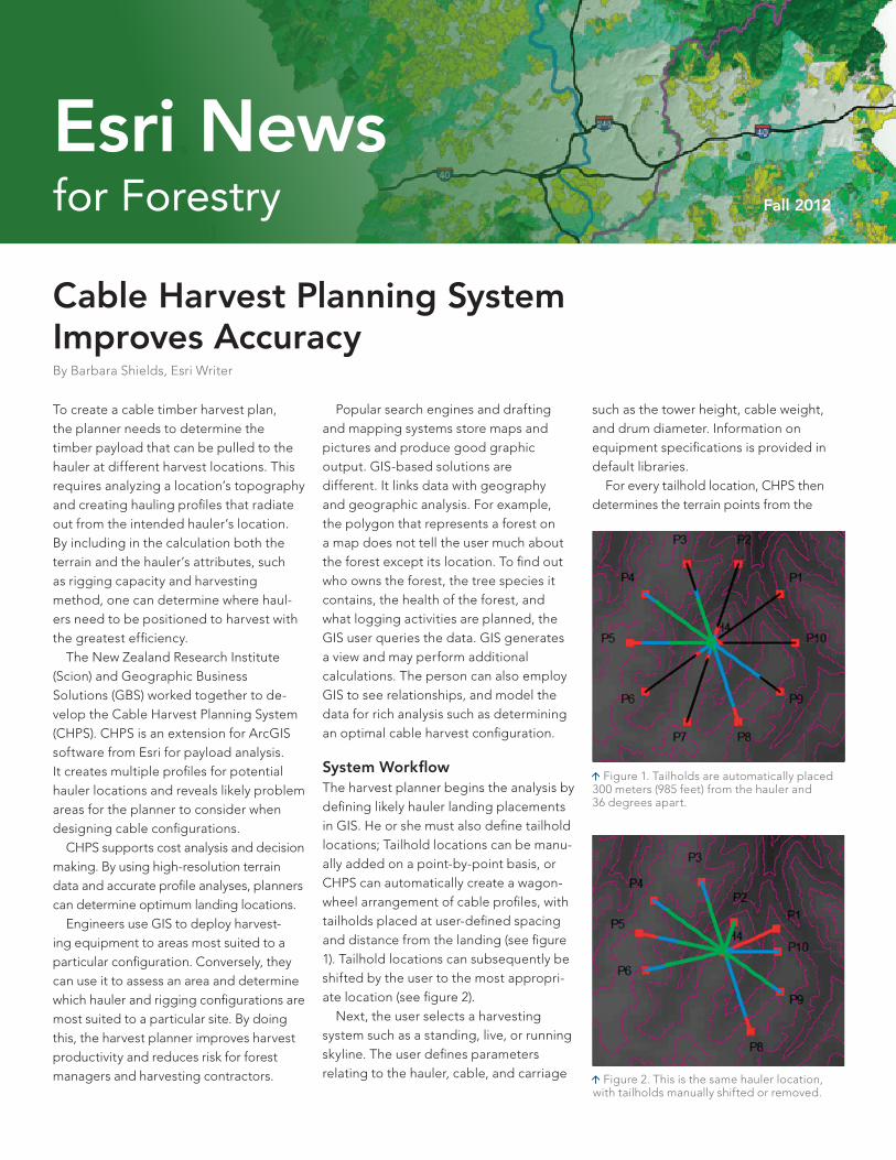
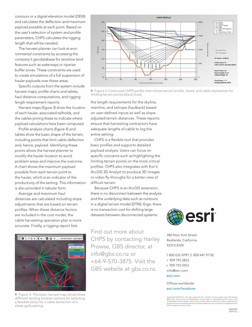
System WorkflowThe harvest planner begins the analysis by defining likely hauler landing placements in GIS. He or she must also define tailhold locations; Tailhold locations can be manu-ally added on a point-by-point basis, or CHPS can automatically create a wagon-wheel arrangement of cable profiles, with tailholds placed at user-defined spacing and distance from the landing (see figure 1). Tailhold locations can subsequently be shifted by the user to the most appropri-ate location (see figure 2). Next, the user selects a harvesting system such as a standing, live, or running skyline. The user defines parameters relating to the hauler, cable, and carriage
Figure 1. Tailholds are automatically placed 300 meters (985 feet) from the hauler and 36 degrees apart.
Figure 2. This is the same hauler location, with tailholds manually shifted or removed.
380 New York Street
Redlands, California
92373-8100
1 800 GIS XPRT (1 800 447 9778)
t 909 793 2853
f 909 793 5953
esri.com
Offices worldwide
esri.com/locations
Copyright © 2013 Esri. All rights reserved. Esri, ArcGIS, the Esri globe logo, 3D Analyst, @esri.com, and esri.com are trademarks, service marks, or registered marks of Esri in the United States, the European Community, or certain other jurisdictions. Other companies and products or services mentioned herein may be trademarks, service marks, or registered marks of their respective mark owners.
G60105ESRI9/13kq
contours or a digital elevation model (DEM) and calculates the deflection and maximum payload possible at each point. Based on the user’s selection of system and profile parameters, CHPS calculates the rigging length that will be needed. The harvest planner can look at envi-ronmental constraints by accessing the company’s geodatabase for sensitive land features such as waterways or riparian buffer zones. These constraints are used to create simulations of a full suspension of hauler payloads over these areas. Specific outputs from the system include harvest maps, profile charts and tables, haul distance computations, and rigging length requirement reports. Harvest maps (figure 3) show the location of each hauler, associated tailholds, and the cables joining these to indicate where payload calculations have been computed. Profile analysis charts (figure 4) and tables show the basic shape of the terrain, including points that limit cable deflection and, hence, payload. Identifying these points allows the harvest planner to modify the hauler location to avoid problem areas and improve the outcome. A chart shows the maximum payload possible from each terrain point to the hauler, which is an indicator of the productivity of the setting. This information is also provided in tabular form. Average and maximum haul distances are calculated including slope adjustments that are based on terrain profiles. When these distance factors are included in the cost model, the cable harvesting operation plan is more accurate. Finally, a rigging report lists
the length requirements for the skyline, mainline, and tailrope (haulback) based on user-defined inputs as well as slope-adjusted terrain distances. These reports ensure that harvesting contractors have adequate lengths of cable to log the entire setting. CHPS is a flexible tool that provides basic profiles and supports detailed payload analysis. Users can focus on specific concerns such as highlighting the limiting terrain points on the most critical profiles. CHPS also integrates with Esri’s ArcGIS 3D Analyst to produce 3D images or video fly-throughs for a better view of difficult terrain. Because CHPS is an ArcGIS extension, there is no disconnect between the analysis and the underlying data such as contours in a digital terrain model (DTM). Ergo, there is no transaction cost for shifting large datasets between disconnected systems.
Find out more about CHPS by contacting Harley Prowse, GBS director, at [email protected] or +64-9-570-3875. Visit the GBS website at gbs.co.nz.
Figure 4. Continued CHPS profile chart shows terrain profile, chord, and cable stylizations for limiting terrain points (black lines).
Figure 3. This basic harvest map shows three different landing location options for selecting a feasible setup for a cable extraction of a steep gully setting.