c3d Content Anz Doc0
14
1 Civil 3D 2012 Country Kit for Australia & New Zealand HORIZONTAL ALIGNMENTS CHEAT SHEET: (using the ANZ CK to get started easily) This doc is a brief summary of how to create simple Horizontal Geometry using Polylines and how to use the inbuilt functionality of the ANZ Country Kit to harness the functionali ty. 1.1 Create Geometry 1.2 Edit Geometry 1.3 Edit Chainage Labels 1.4 Assign Styles 1.5 Labels & Tables 1.6 Edit Properties Entity Based Design: In this example, the curve is maintaining tangency with the lines as it is a Floating Element The goal of this brief doc is to show how to convert Polylines into intelligent objects. NOTE: This is the simplified method for getting started - please see the help file and tutorials for a more complete tutorial on using more powerful tools for creating Horizontal Geometry. Floating Curve
-
Upload
putra-sabalae -
Category
Documents
-
view
220 -
download
0
Transcript of c3d Content Anz Doc0
8/18/2019 c3d Content Anz Doc0
http://slidepdf.com/reader/full/c3d-content-anz-doc0 1/13
1 Civil 3D 2012 Country Kit for Australia & New Zealand
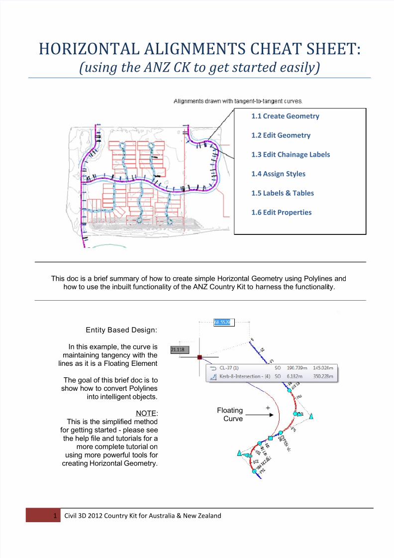
HORIZONTAL ALIGNMENTS CHEAT SHEET:
(using the ANZ CK to get started easily)
This doc is a brief summary of how to create simple Horizontal Geometry using Polylines andhow to use the inbuilt functionality of the ANZ Country Kit to harness the functionality.
1.1 Create Geometry
1.2 Edit Geometry
1.3 Edit Chainage Labels
1.4 Assign Styles
1.5 Labels & Tables
1.6 Edit Properties
Entity Based Design:
In this example, the curve ismaintaining tangency with the
lines as it is a Floating Element
The goal of this brief doc is to
show how to convert Polylinesinto intelligent objects.
NOTE:This is the simplified method
for getting started - please seethe help file and tutorials for a
more complete tutorial onusing more powerful tools for
creating Horizontal Geometry.
FloatingCurve

8/18/2019 c3d Content Anz Doc0
http://slidepdf.com/reader/full/c3d-content-anz-doc0 2/13
2 Civil 3D 2012 Country Kit for Australia & New Zealand
1. 1 Create the Geometry from Polylines:
• Draw a 2D Polyl ine,without the curves.
• On the Ribbon Click Ali gnments... Create from Objects.
• Select the Polyline
• Fill in the relevant details asper the screen shot below
• FLOATING Curves areautomatically created...
The Alignment style
controls the visual
appearance of thealignment components -
Line type, colour etc.
Select the relevant label
set for chainages,
geometry points etc
("ANZ_no labels" is a blank
label set)
Leave this clicked to get
the horizontal curves
added automatically.
Default Radius of the
curves can be specified.
Leave this on Centreline
2D PolylineNo Curves
8/18/2019 c3d Content Anz Doc0
http://slidepdf.com/reader/full/c3d-content-anz-doc0 3/13
3 Civil 3D 2012 Country Kit for Australia & New Zealand
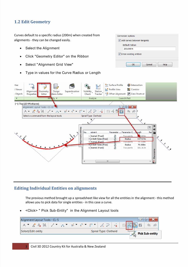
1.2 Edit Geometry
Curves default to a specific radius (200m) when created from
alignments - they can be changed easily.
• Select the Alignment
• Click "Geometry Editor" on the Ribbon
• Select "Alignment Grid View"
• Type in values for the Curve Radius or Length
Editing Individual Entities on alignments
The previous method brought up a spreadsheet like view for all the entities in the alignment - this method
allows you to pick data for single entities - in this case a curve.
• <Click> " Pick Sub-Entity" in the Alignment Layout tools
8/18/2019 c3d Content Anz Doc0
http://slidepdf.com/reader/full/c3d-content-anz-doc0 4/13
4 Civil 3D 2012 Country Kit for Australia & New Zealand
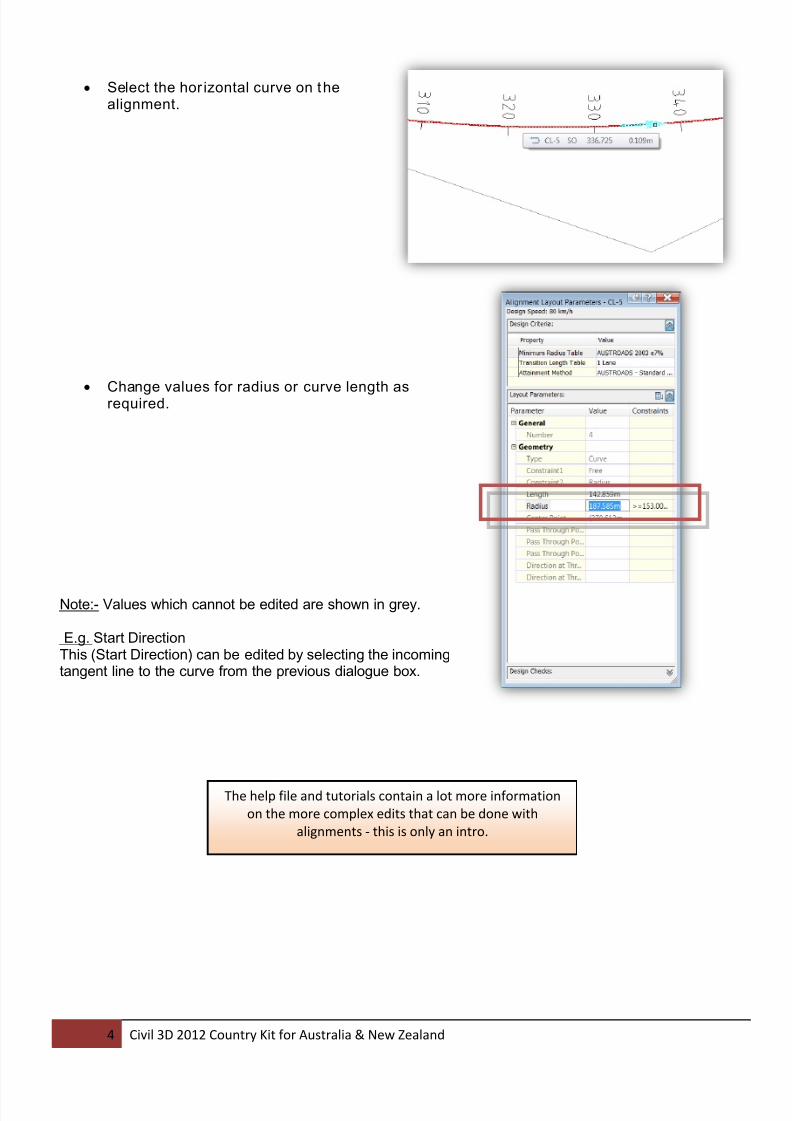
• Select the hor izontal curve on thealignment.
•
Change values for radius or curve length asrequired.
Note:- Values which cannot be edited are shown in grey.
E.g. Start DirectionThis (Start Direction) can be edited by selecting the incomingtangent line to the curve from the previous dialogue box.
The help file and tutorials contain a lot more information
on the more complex edits that can be done with
alignments - this is only an intro.
8/18/2019 c3d Content Anz Doc0
http://slidepdf.com/reader/full/c3d-content-anz-doc0 5/13
5 Civil 3D 2012 Country Kit for Australia & New Zealand
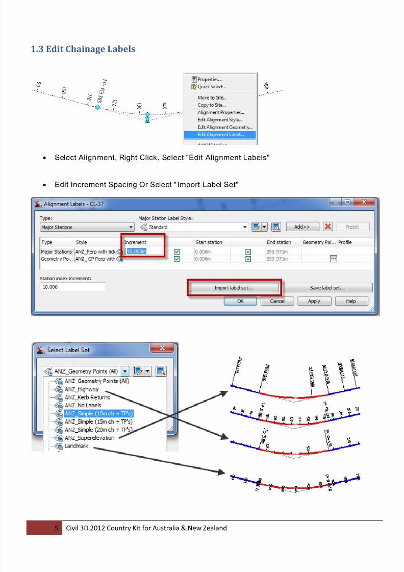
1.3 Edit Chainage Labels
• Select Alignment, Right Click, Select "Edit Alignment Labels"
• Edit Increment Spacing Or Select " Import Label Set"
8/18/2019 c3d Content Anz Doc0
http://slidepdf.com/reader/full/c3d-content-anz-doc0 6/13
6 Civil 3D 2012 Country Kit for Australia & New Zealand
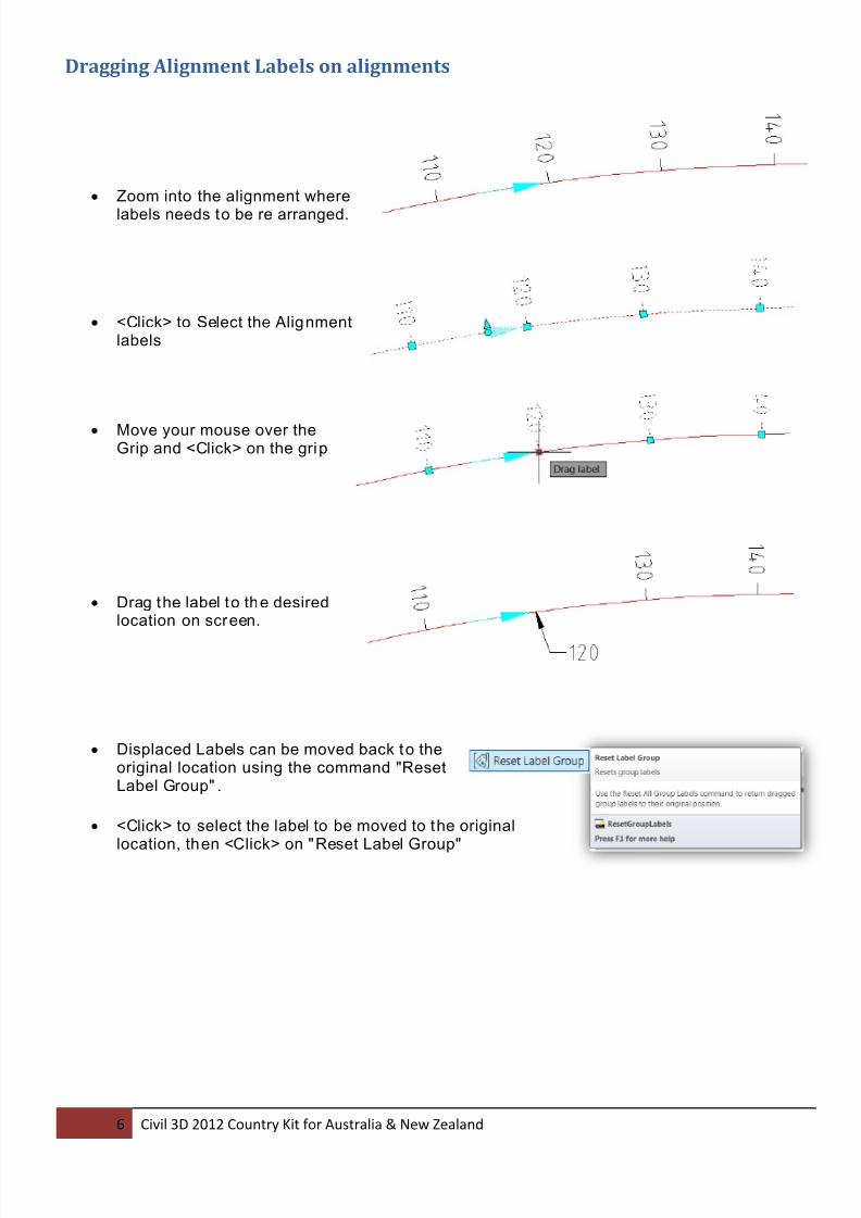
Dragging Alignment Labels on alignments
• Zoom into the alignment where
labels needs to be re arranged.
• <Click> to Select the Alignmentlabels
• Move your mouse over theGrip and <Click> on the grip
• Drag the label to the desiredlocation on screen.
• Displaced Labels can be moved back to theoriginal location using the command "ResetLabel Group" .
• <Click> to select the label to be moved to the originallocation, then <Click> on "Reset Label Group"
8/18/2019 c3d Content Anz Doc0
http://slidepdf.com/reader/full/c3d-content-anz-doc0 7/13
7 Civil 3D 2012 Country Kit for Australia & New Zealand
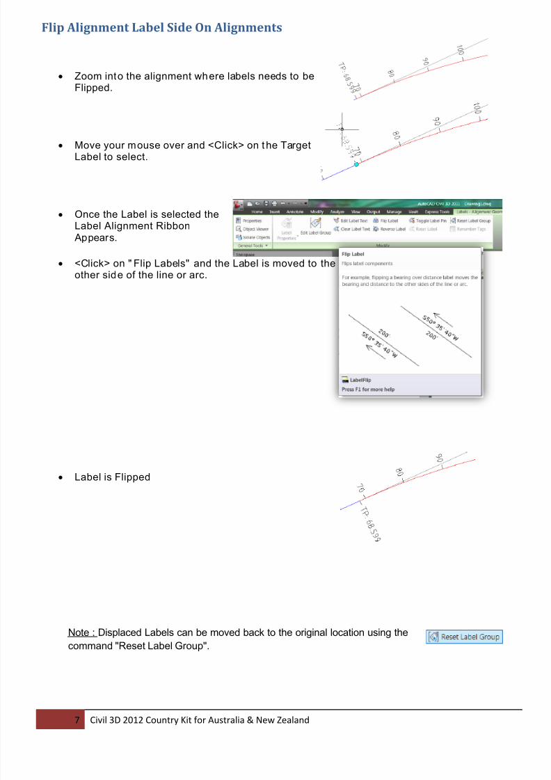
Flip Alignment Label Side On Alignments
• Zoom into the alignment where labels needs to beFlipped.
• Move your mouse over and <Click> on the TargetLabel to select.
• Once the Label is selected theLabel Alignment Ribbon Appears.
• <Click> on " Flip Labels" and the Label is moved to the
other side of the line or arc.
• Label is Flipped
Note : Displaced Labels can be moved back to the original location using the
command "Reset Label Group".
8/18/2019 c3d Content Anz Doc0
http://slidepdf.com/reader/full/c3d-content-anz-doc0 8/13
8 Civil 3D 2012 Country Kit for Australia & New Zealand
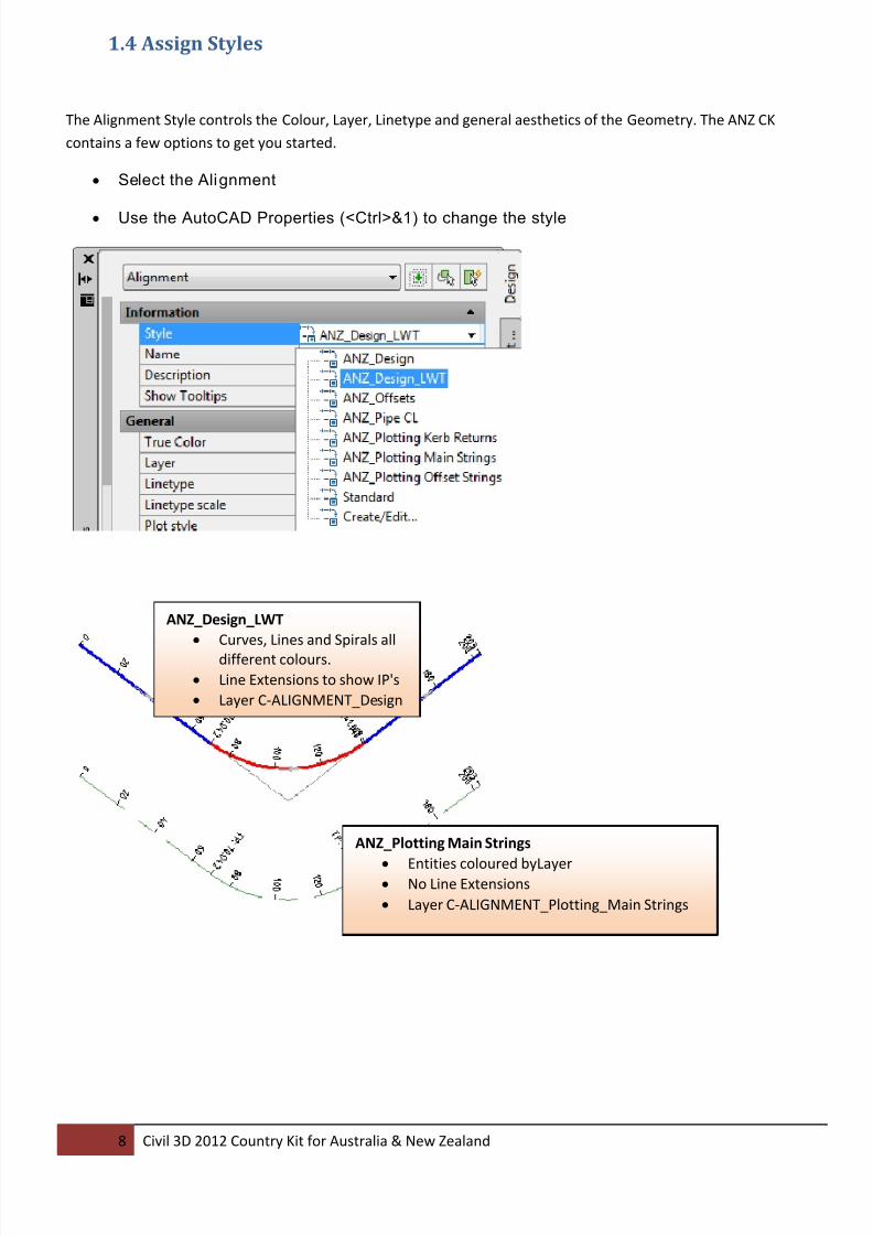
1.4 Assign Styles
The Alignment Style controls the Colour, Layer, Linetype and general aesthetics of the Geometry. The ANZ CK
contains a few options to get you started.
• Select the Alignment
• Use the AutoCAD Properties (<Ctrl>&1) to change the style
ANZ_Design_LWT
• Curves, Lines and Spirals all
different colours.
• Line Extensions to show IP's
• Layer C-ALIGNMENT_Design
ANZ_Plotting Main Strings
• Entities coloured byLayer• No Line Extensions
• Layer C-ALIGNMENT_Plotting_Main Strings
8/18/2019 c3d Content Anz Doc0
http://slidepdf.com/reader/full/c3d-content-anz-doc0 9/13
9 Civil 3D 2012 Country Kit for Australia & New Zealand
1.5 Labels & Tables
Offset Labels:
Segment Labels
Tables
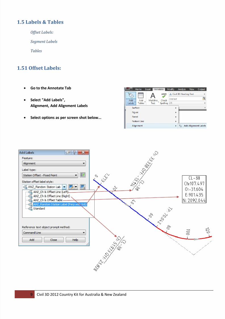
1.51 Offset Labels:
• Go to the Annotate Tab
• Select "Add Labels",
Alignment, Add Alignment Labels
• Select options as per screen shot below...
8/18/2019 c3d Content Anz Doc0
http://slidepdf.com/reader/full/c3d-content-anz-doc0 10/13
10 Civil 3D 2012 Country Kit for Australia & New Zealand
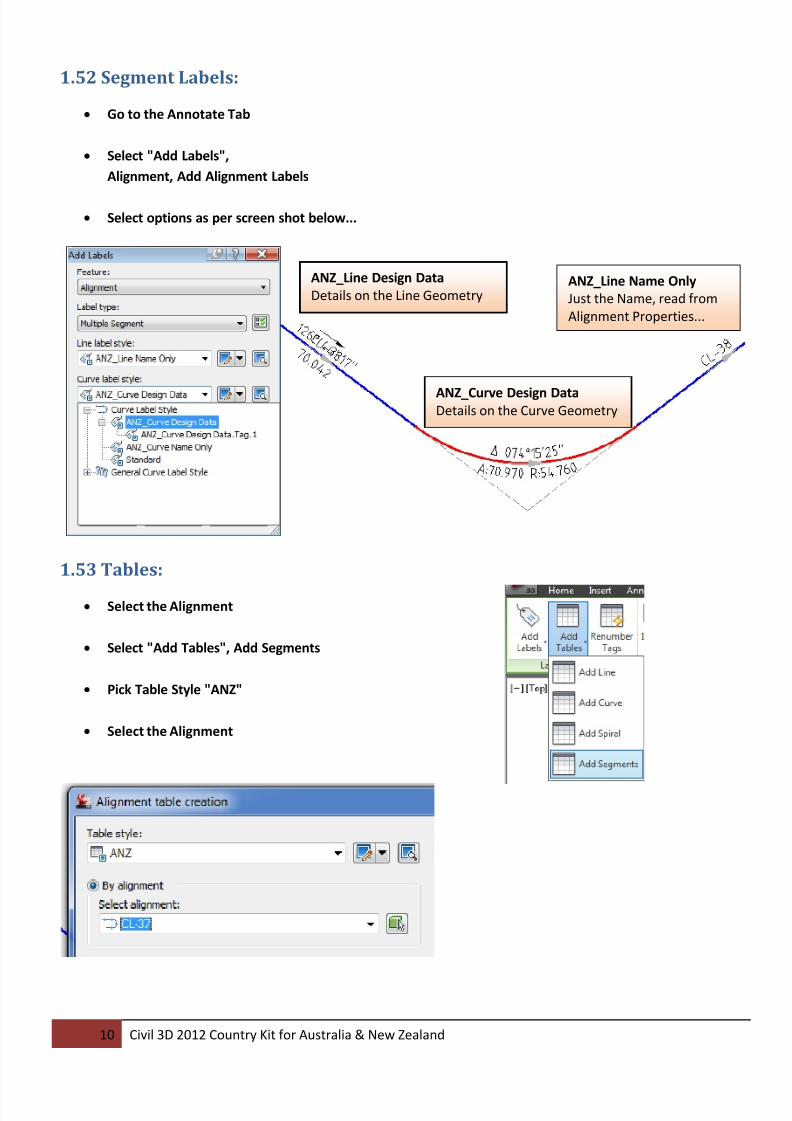
1.52 Segment Labels:
• Go to the Annotate Tab
• Select "Add Labels",
Alignment, Add Alignment Labels
• Select options as per screen shot below...
1.53 Tables:
• Select the Alignment
• Select "Add Tables", Add Segments
• Pick Table Style "ANZ"
• Select the Alignment
ANZ_Curve Design DataDetails on the Curve Geometry
ANZ_Line Design Data
Details on the Line GeometryANZ_Line Name Only
Just the Name, read from
Alignment Properties...
8/18/2019 c3d Content Anz Doc0
http://slidepdf.com/reader/full/c3d-content-anz-doc0 11/13
11 Civil 3D 2012 Country Kit for Australia & New Zealand
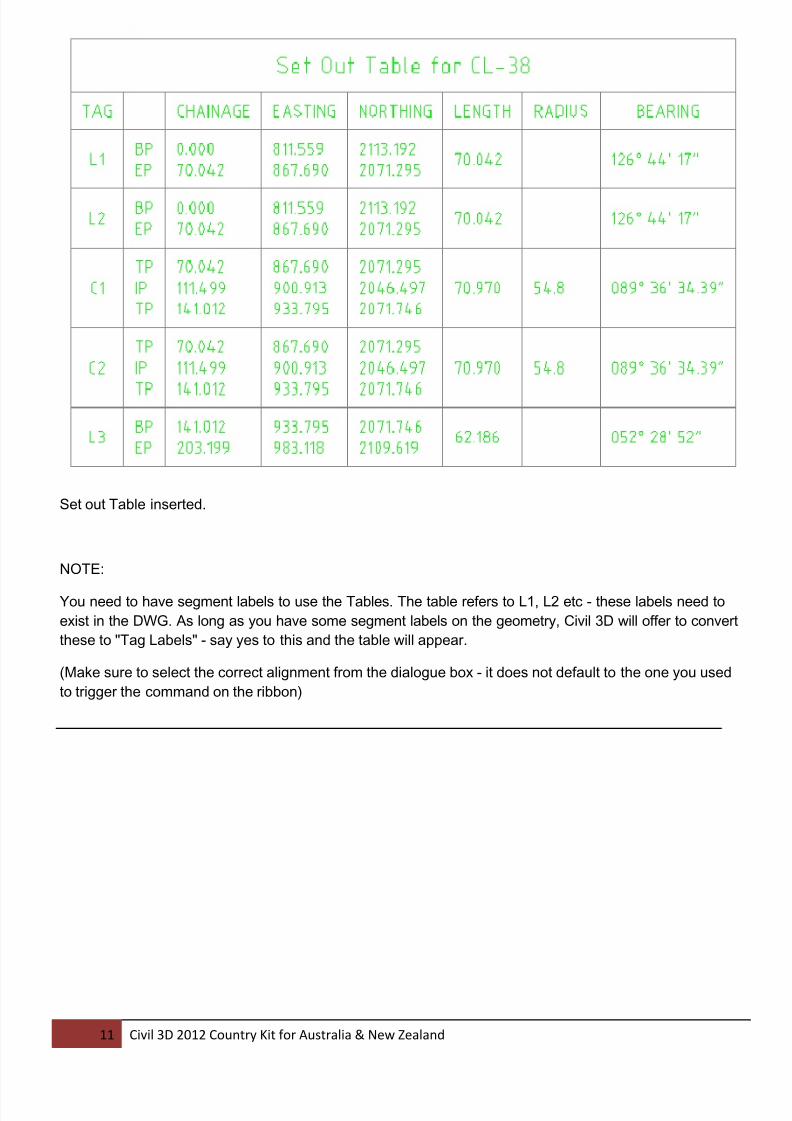
Set out Table inserted.
NOTE:
You need to have segment labels to use the Tables. The table refers to L1, L2 etc - these labels need to
exist in the DWG. As long as you have some segment labels on the geometry, Civil 3D will offer to convert
these to "Tag Labels" - say yes to this and the table will appear.
(Make sure to select the correct alignment from the dialogue box - it does not default to the one you used
to trigger the command on the ribbon)
8/18/2019 c3d Content Anz Doc0
http://slidepdf.com/reader/full/c3d-content-anz-doc0 12/13
12 Civil 3D 2012 Country Kit for Australia & New Zealand
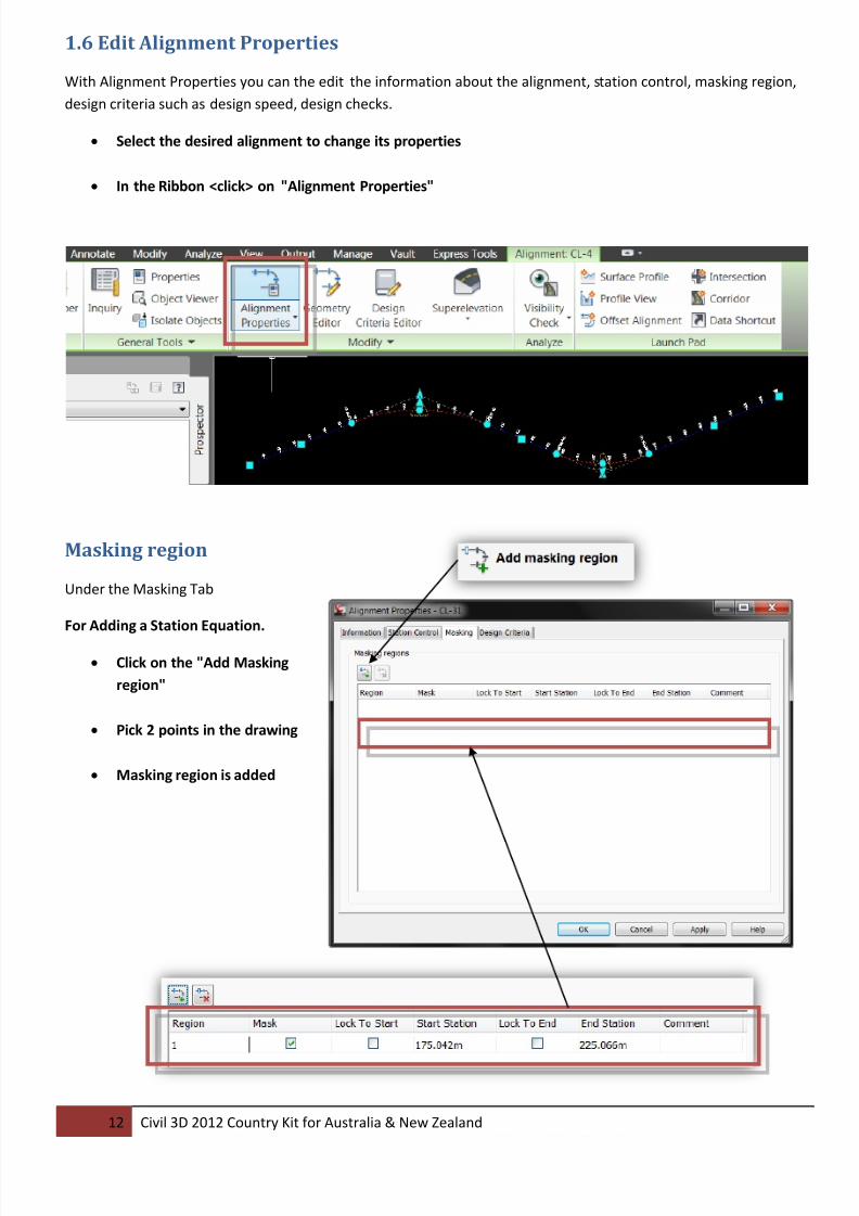
1.6 Edit Alignment Properties
With Alignment Properties you can the edit the information about the alignment, station control, masking region,
design criteria such as design speed, design checks.
• Select the desired alignment to change its properties
• In the Ribbon <click> on "Alignment Properties"
Masking region
Under the Masking Tab
For Adding a Station Equation.
• Click on the "Add Masking
region"
• Pick 2 points in the drawing
• Masking region is added

8/18/2019 c3d Content Anz Doc0
http://slidepdf.com/reader/full/c3d-content-anz-doc0 13/13
13 Civil 3D 2012 Country Kit for Australia & New Zealand
Specify Design Speed and Criteria
For Superelevation and Criteria based Widening, you need to specify the Design Speed and the Criteria File.
• Add Design Speeds as shown in the Screen Capture below.
• Specify a Design Criteria File as shows in the same Screen Capture.
Austroads 2009
As requested by the user base, the Australian
Design Criteria Files have been updated to the
Austroads 2009 Standards