
LINEAR ENCODER - MUTOHdeji/pdf_18a/linear...LINEAR ENCODER - MUTOH ... 50
Upload
nguyennguyetCategory
view
225download
3
Ⅱ̶65 Ⅱ̶66
CルーブリニアウェイHC-Lube Linear Way MHLinear Way H
英_Ⅱ_065-084特長H.indd 65-66 11.6.2 10:26:56 AM
1N=0.102kgf=0.2248lbs.1mm=0.03937inch
LWHLinear Way H
C-Lube Linear Way MHC-Lube Linear
MHC-Lube maintenance free series
Aquamarine endplate for identification of C-Lube Linear Way
Casing
C-Lube
Steel ball
End plate
Under seal
Ball retaining band
End seal
Grease nipple
Slide unit
Track rail
Ⅱ̶68
S
Ⅱ̶67
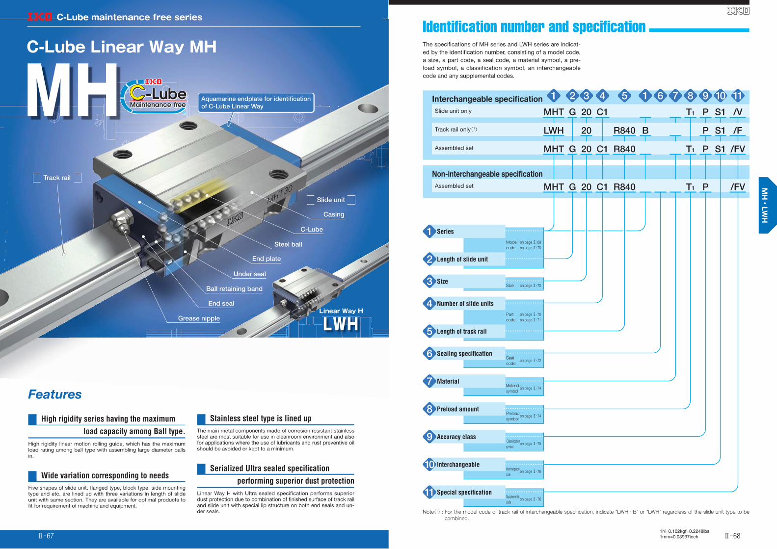
Identifi cation number and specifi cation The specifi cations of MH series and LWH series are indicat-ed by the identifi cation number, consisting of a model code, a size, a part code, a seal code, a material symbol, a pre-load symbol, a classification symbol, an interchangeable code and any supplemental codes.
Features
High rigidity series having the maximum
load capacity among Ball type.
High rigidity linear motion rolling guide, which has the maximum load rating among ball type with assembling large diameter balls in.
Wide variation corresponding to needs
Five shapes of slide unit, fl anged type, block type, side mounting type and etc. are lined up with three variations in length of slide unit with same section. They are available for optimal products to fi t for requirement of machine and equipment.
Stainless steel type is lined up
The main metal components made of corrosion resistant stainless steel are most suitable for use in cleanroom environment and also for applications where the use of lubricants and rust preventive oil should be avoided or kept to a minimum.
Serialized Ultra sealed specifi cation
performing superior dust protection
Linear Way H with Ultra sealed specification performs superior dust protection due to combination of fi nished surface of track rail and slide unit with special lip structure on both end seals and un-der seals.
Interchangeable specifi cation 1 2 3 4 5 1 6 7 8 9 10 11Slide unit only MHT G 20 C1 T1 P S1 /V
Track rail only(1) LWH 20 R840 B P S1 /F
Assembled set MHT G 20 C1 R840 T1 P S1 /FV
Non-interchangeable specifi cation
Assembled set MHT G 20 C1 R840 T1 P /FV
Series1Model
code
on page Ⅱ̶69
on page Ⅱ̶70
Length of slide unit2
Size3Size on page Ⅱ̶70
Number of slide units4Part
code
on page Ⅱ̶70
on page Ⅱ̶71
Length of track rail5
Sealing specifi cation6Seal
codeon page Ⅱ̶72
Material7Material
symbolon page Ⅱ̶74
Preload amount 8Preload
symbolon page Ⅱ̶74
Accuracy class9 Classifi cation
symbolon page Ⅱ̶75
Interchangeable10Interchangeable
codeon page Ⅱ̶76
Special specifi cation11Supplemental
codeon page Ⅱ̶76
Note(1) : For the model code of track rail of interchangeable specifi cation, indicate “LWH…B” or “LWH” regardless of the slide unit type to be
combined.
英_Ⅱ_065-084特長H.indd 67-68 11.6.2 10:26:57 AM
1N=0.102kgf=0.2248lbs.1mm=0.03937inchⅡ̶69
S
Ⅱ̶70
S
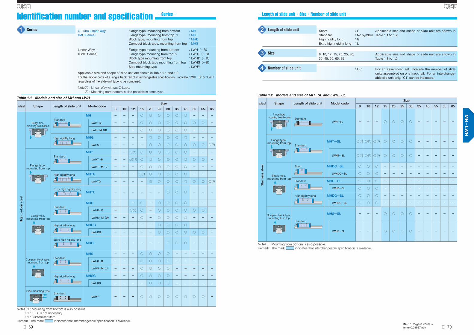
-Length of slide unit・Size・Number of slide unit-Identifi cation number and specifi cation -Series-
C-Lube Linear Way(MH Series)
Flange type, mounting from bottomFlange type, mounting from top(2)Block type, mounting from topCompact block type, mounting from top
: MH: MHT: MHD: MHS
Linear Way(1)(LWH Series)
Flange type mounting from bottom Flange type mounting from top(2) Block type mounting from top Compact block type mounting from topSide mounting type
: LWH(…B): LWHT(…B): LWHD(…B): LWHS(…B): LWHY
Applicable size and shape of slide unit are shown in Table 1.1 and 1.2.For the model code of a single track rail of interchangeable specifi cation, indicate “LWH…B” or “LWH” regardless of the slide unit type to be combined.
Note(1) : Linear Way without C-Lube.
(2) : Mounting from bottom is also possible in some type.
Series1
Table 1.1 Models and size of MH and LWH
Material Shape Length of slide unit Model codeSize
8 10 12 15 20 25 30 35 45 55 65 85
Hig
h ca
rbo
n st
eel
MH - - - ○ ○ ○ ○ ○ ○ - - -
LWH…B - - - ○ ○ ○ ○ ○ ○ ○ ○ -
LWH…M(U) - - - ○ ○ ○ ○ ○ ○ - - -
MHG - - - - ○ ○ ○ ○ ○ - - -
LWHG - - - - ○ ○ ○ ○ ○ ○ ○ ○(3)
MHT - - ○(1) ○ ○ ○ ○ ○ ○ - - -
LWHT…B - - ○(1)(2) ○ ○ ○ ○ ○ ○ ○ ○ -
LWHT…M(U) - - - ○ ○ ○ ○ ○ ○ - - -
MHTG - - - ○(1) ○ ○ ○ ○ ○ - - -
LWHTG - - - - ○ ○ ○ ○ ○ ○ ○ ○(3)
MHTL - - - - - - ○ ○ ○ - - -
MHD - ○ ○ - ○ ○ ○ ○ - - -
LWHD…B - ○(2) ○ - ○ ○ ○ ○ ○ ○
LWHD…M(U) - - - ○ - ○ ○ ○ ○ - - -
MHDG - - - - - ○ ○ ○ ○ - - -
LWHDG - - - - - ○ ○ ○ ○ ○ ○ -
MHDL - - - - - - ○ ○ ○ - - -
MHS - - - ○ ○ ○ ○ - - - - -
LWHS…B - - - ○ ○ ○ ○ - - - - -
LWHS…M(U) - - - ○ ○ ○ ○ - - - - -
MHSG - - - ○ ○ ○ ○ - - - - -
LWHSG - - - - ○ ○ ○ - - - - -
LWHY - - - ○ ○ ○ ○ ○ ○ ○ ○ -
Notes(1) : Mounting from bottom is also possible.
(2) : “…B” is not necessary.
(3) : Customised item.
Remark : The mark indicates that interchangeable specifi cation is available.
Flange type, mounting from bottom
Standard
High rigidity long
Flange type, mounting from top
Standard
High rigidity long
Extra high rigidity long
Block type, mounting from top
Standard
High rigidity long
Extra high rigidity long
Compact block type, mounting from top
Standard
High rigidity long
Side mounting typeStandard
Table 1.2 Models and size of MH...SL and LWH...SL
Material Shape Length of slide unit Model codeSize
8 10 12 15 20 25 30 35 45 55 65 85
Sta
inle
ss s
teel
LWH…SL - - - ○ ○ ○ ○ - - - - -
MHT…SL ○(1)○(1)○(1) ○ ○ ○ ○ - - - - -
LWHT…SL ○(1)○(1)○(1) ○ ○ ○ ○ - - - - -
MHDC…SL ○ ○ ○ - - - - - - - - -
LWHDC…SL ○ ○ ○ - - - - - - - - -
MHD…SL ○ ○ ○ - - - - - - - - -
LWHD…SL ○ ○ ○ - - - - - - - - -
MHDG…SL ○ ○ ○ - - - - - - - - -
LWHDG…SL ○ ○ ○ - - - - - - - - -
MHS…SL - - - ○ ○ ○ ○ - - - - -
LWHS…SL - - - ○ ○ ○ ○ - - - - -
Note(1) : Mounting from bottom is also possible.
Remark : The mark indicates that interchangeable specifi cation is available.
Flange type, mounting from bottom Standard
Flange type, mounting from top
Standard
Block type, mounting from top
Short
Standard
High rigidity long
Compact block type, mounting from top
Standard
ShortStandardHigh rigidity longExtra high rigidity long
:C:No symbol:G:L
Applicable size and shape of slide unit are shown in Table 1.1 to 1.2.
8, 10, 12, 15, 20, 25, 30, 35, 45, 55, 65, 85
Applicable size and shape of slide unit are shown in Table 1.1 to 1.2.
:C○ For an assembled set, indicate the number of slide units assembled on one track rail. For an interchange-able slid unit only, “C1” can be indicated.
Length of slide unit2
Size3
Number of slide unit4
英_Ⅱ_065-084特長H.indd 69-70 11.6.2 10:27:21 AM

1N=0.102kgf=0.2248lbs.1mm=0.03937inchⅡ̶71
S
Ⅱ̶72
S
-Length of track rail・Sealing--Length of track rail-
:R○ Indicate the length of track rail in mm. For standard and maximum lengths, see Table 2.1 and 2.2.
Length of track rail5 Standard specifi cationUltra sealed specifi cationUltra sealed track rail mounting from bottom
:No symbol:M:MU
Applicable size and shape of slide unit are shown in Table 1.1and 1.2.For the specifi cations of ultra sealed track rail mounted from bottom MU, the slide unit of the ultra sealed specifi cation M is applicable. Table 2.3 and 2.4 show the specifi cation of track rail.
Sealing specifi cation6
Table 2.2 Standard and maximum length of Stainless steel track rails
unit : mm
Model numberItem
MH 8…SLLWH 8…SL
MH 10…SLLWH 10…SL
MH 12…SLLWH 12…SL
MH 15…SLLWH 15…SL
MH 20…SLLWH 20…SL
MH 25…SLLWH 25…SL
MH 30…SLLWH 30…SL
Standard length L(n)
40( 2) 80( 4)120( 6)160( 8)200(10)240(12)280(14)
50( 2)100( 4)150( 6)200( 8)250(10)300(12)350(14)400(16)450(18)500(20)
80( 2)160( 4)240( 6)320( 8)400(10)480(12)560(14)640(16)720(18)
180( 3)240( 4)360( 6)480( 8)660(11)
240( 4)480( 8)660(11)840(14)
240( 4)480( 8)660(11)840(14)
480( 6) 640( 8) 800(10)1 040(13)
Mounting hole pitch F 20 25 40 60 60 60 80E 10 12.5 20 30 30 30 40
Referencedimension E(1)
Over (Incl.) 4.5 5 5.5 7 8 9 10Under 14.5 17.5 25.5 37 38 39 50
Maximum length(2) 480(1 000)
850(1 000)
1 000(1 480)
1 200(1 500)
1 200(3 000)
1 200(3 000)
1 200(2 960)
Notes(1) : Not applied to optional specifi cation “female threads for bellows” (supplemental code “/J”, “/JJ”) (2) : The track rails can be manufactured up to the maximum length shown in parentheses. If required, please consult R.
Remarks 1 : The above table shows representative model number but is applicable to all models of the same size.
2 : For the model code of track rail of interchangeable specifi cation, indicate “LWH...SL” regardless of slide unit type to be combined.
n(Number of mounting holes)
L
EFE
Table 2.1 Standard and maximum lengths of high carbon steel track rails
unit : mm
Model numberItem
MH 12LWH 12
MH 15LWH 15…B
MH 20LWH 20…B
MH 25LWH 25…B
MH 30LWH 30…B
Standard length L(n)
80( 2)160( 4)240( 6)320( 8)400(10)480(12)560(14)640(16)720(18)
180( 3)240( 4)360( 6)480( 8)660(11)900(15)
1 200(20)
240( 4) 480( 8) 660(11) 840(14)1 020(17)1 200(20)1 500(25)
240( 4) 480( 8) 660(11) 840(14)1 020(17)1 200(20)1 500(25)1 980(33)
480( 6) 640( 8) 800(10)1 040(13)1 200(15)1 520(19)2 000(25)
Pitch of mounting holes F 40 60 60 60 80E 20 30 30 30 40
Standard rangeof E(1)
incl. 5.5 7 8 9 10under 25.5 37 38 39 50
Maximum length(2) 1 480 1 500(3 000)
1 980(3 000)
3 000(3 960)
2 960(4 000)
Model numberItem
MH 35LWH 35…B
MH 45LWH 45…B LWH 55…B LWH 65…B LWH 85(3)
Standard length L(n)
480( 6)640( 8)800(10)
1 040(13)1 200(15)1 520(19)
840( 8)1 050(10)1 260(12)1 470(14)1 995(19)
840( 7)1 200(10)1 560(13)1 920(16)3 000(25)
1 500(10)1 950(13)3 000(20)
―
Pitch of mounting holes F 80 105 120 150 180E 40 52.5 60 75 90
Standard rangeof E(1)
incl. 10 12.5 15 17 23under 50 65 75 92 113
Maximum length(2) 2 960(4 000)
2 940(3 990)
3 000(3 960)
3 000(3 900)
2 880
Notes(1) : Not applicable to the track rail with female threads for bellows (supplemental code “/J”).(2) : Track rails with the maximum lengths in parentheses can be manufactured. Consult R for further information.
(3) : Customized item.
Remarks 1 : The above table shows representative model numbers but is applicable to all models of the same size.
2 : For the model code of track rail of interchangeable specifi cation, indicate “LWH” for size 12 and “LWH...B” for size 15 or larger
regardless of slide unit type to be combined.
3 : In Ultra sealed type, see Table 2.3 and 2.4.
n(Number of mounting holes)
L
EFE
英_Ⅱ_065-084特長H.indd 71-72 11.6.2 10:27:25 AM

1N=0.102kgf=0.2248lbs.1mm=0.03937inchⅡ̶73
S
Ⅱ̶74
S
-Material・Preload amount--Length of track rail-
Table 2.3 Standard and maximum lengths of Ultra sealed specifi cation high carbon steel track rails
unit : mm
Model numberItem
LWH15…M LWH20…M LWH25…M LWH30…M LWH35…M LWH45…M
Standard length L(n)
180( 3)240( 4)360( 6)480( 8)660(11)
240( 4)480( 8)660(11)840(14)
1 020(17)1 200(20)1 500(25)
240( 4)480( 8)660(11)840(14)
1 020(17)1 200(20)1 500(25)
480( 6)640( 8)800(10)
1 040(13)1 200(15)1 520(19)
480( 6)640( 8)800(10)
1 040(13)1 200(15)1 520(19)
840( 8)1 050(10)1 260(12)1 470(14)1 995(19)
Pitch of mounting holes F 60 60 60 80 80 105E 30 30 30 40 40 52.5
Standard rangeof E(1)
incl. 7 8 9 10 10 12.5under 37 38 39 50 50 65
Maximum length 1 500 1 980 3 000 2 960 2 960 2 940Maximum number of butt-jointing rails 3 3 3 3 3 3Maximum length of butt-jointing rails 4 200 5 640 8 700 8 480 8 480 8 295
Note(1) : Not applicable to the track rail with female threads for bellows (supplemental code “/J”).Remark : The above table shows representative model numbers but is applicable to all models of the same size.
n(Number of mounting holes)
L
EFE
Table 2.4 Standard and maximum lengths of Ultra sealed track rail mounting from bottom
unit : mm
Model numberItem
LWH15…MU LWH20…MU LWH25…MU LWH30…MU LWH35…MU LWH45…MU
Standard length L(n)
180( 3)240( 4)360( 6)480( 8)660(11)
240( 4)480( 8)660(11)840(14)
1 020(17)1 200(20)1 500(25)
240( 4)480( 8)660(11)840(14)
1 020(17)1 200(20)1 500(25)
480( 6)640( 8)800(10)
1 040(13)1 200(15)1 520(19)
480( 6)640( 8)800(10)
1 040(13)1 200(15)1 520(19)
840( 8)1 050(10)1 260(12)1 470(14)1 995(19)
Pitch of mounting holes F 60 60 60 80 80 105E 30 30 30 40 40 52.5
Standard rangeof E(1)
incl. 7 8 9 10 10 12.5under 37 38 39 50 50 65
Maximum length 1 500 1 980 3 000 2 960 2 960 2 940Maximum number of butt-jointing rails 3 3 3 3 3 3Maximum length of butt-jointing rails 4 200 5 640 8 700 8 480 8 480 8 295
Note(1) : Not applicable to the track rail with female threads for bellows (supplemental code “/J”).Remarks 1 : The above table shows representative model numbers but is applicable to all models of the same size.
2 : The track rail mounting bolts are not appended. Hexagon socket head bolts of JIS B 1176 with strength 12.9 or equivalent is rec-
ommended
n(Number of mounting holes)
F EE
High carbon steelStainless steel
:No symbol:SL
Applicable sizes are shown in Table 1.1 to 1.2.
ClearanceStandardLight preloadMedium preloadHeavy preload
:T0
:No symbol:T1
:T2
:T3
Specify this items for an assembled set or an inter-changeable single slide unit.Applicable preload and size are shown in Table 3 to 4.
Material7
Preload amount8
Table 3 Preload amount
Item
Preloadtype
SymbolPreload amount
NApplicatin
Clearance T0 0(1) ・ Very smooth motionStandard (No symbol) 0(2) ・ Smooth and precise motion
Light preload T1 0.02C0
・Medium vibration・ Load is evenly balanced.・ Smooth and precise motion
Medium preload T2 0.05C0
・Medium vibration・Medium overhung load
Heavy preload T3 0.08C0
・ Vibration and/or shocks・ Large overhung load・ Heavy cutting
Notes(1) : Zero or minimal amount of clearance
(2) : Zero or minimal amount of preload
Remark : C0 means the basic static load rating.
Table 4 Applicable preload
Size
Preload class and symbol
Clearance(T0)
Standard(No symbol)
Light preload(T1)
Medium preload(T2)
Heavy preload(T3)
8 ○ ○ ○ - -10 ○ ○ ○ - -12 ○ ○ ○ - -15 - ○ ○ ○ ○20 - ○ ○ ○ ○25 - ○ ○ ○ ○30 - ○ ○ ○ ○35 - ○ ○ ○ ○45 - ○ ○ ○ ○55 - ○ ○ ○ ○65 - ○ ○ ○ ○85 - ○ ○ ○ ○
Remark : The mark indicates that it is also applicable to interchangeable specifi cation.
英_Ⅱ_065-084特長H.indd 73-74 11.6.2 10:27:26 AM
1N=0.102kgf=0.2248lbs.1mm=0.03937inchⅡ̶75
S
Ⅱ̶76
S
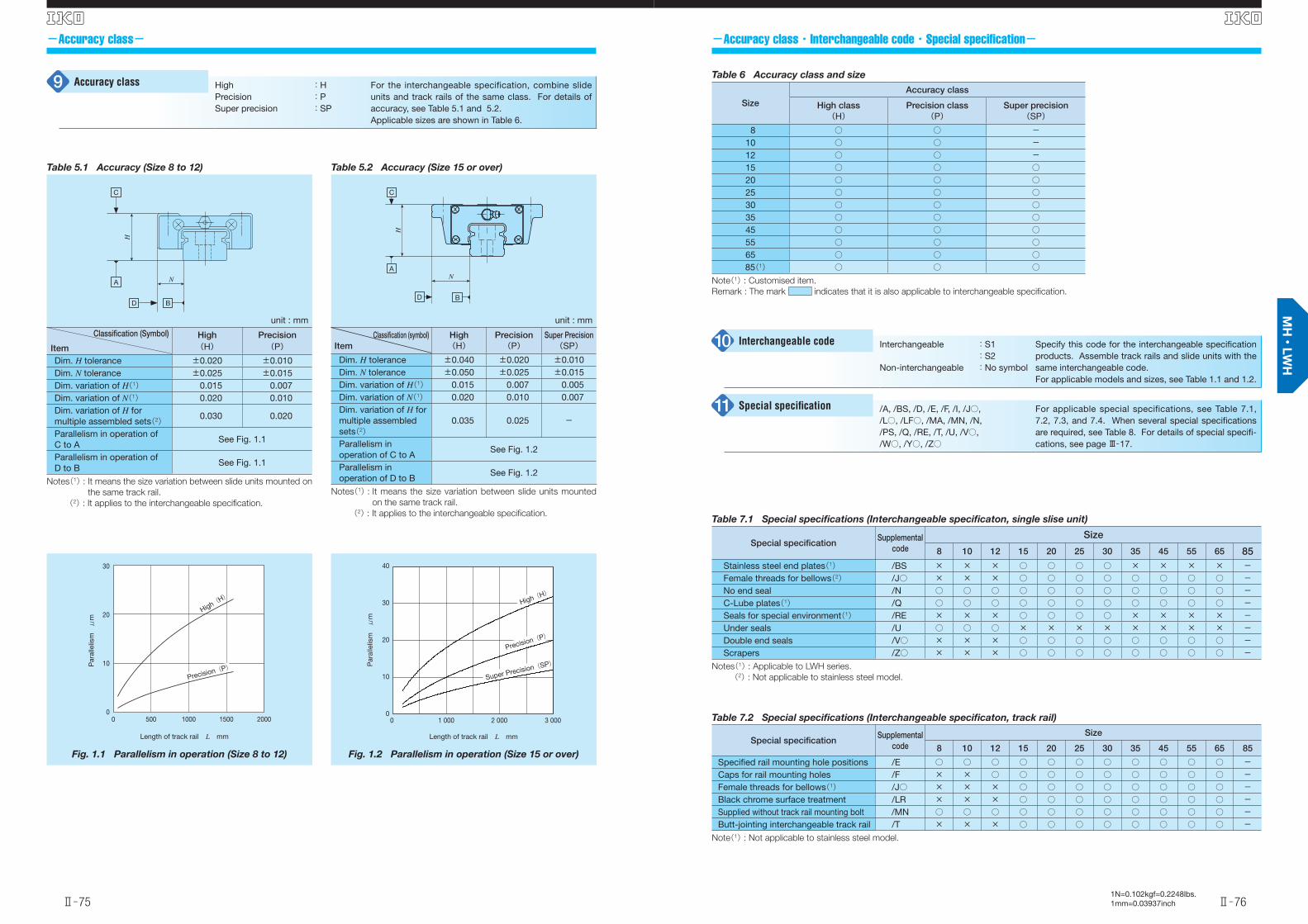
-Accuracy class・Interchangeable code・Special specifi cation-
Interchangeable
Non-interchangeable
:S1:S2:No symbol
Specify this code for the interchangeable specifi cation products. Assemble track rails and slide units with the same interchangeable code.For applicable models and sizes, see Table 1.1 and 1.2.
/A, /BS, /D, /E, /F, /I, /J○, /L○, /LF○, /MA, /MN, /N, /PS, /Q, /RE, /T, /U, /V○, /W○, /Y○, /Z○
For applicable special specifications, see Table 7.1, 7.2, 7.3, and 7.4. When several special specifi cations are required, see Table 8. For details of special specifi -cations, see page Ⅲ̶17.
Special specifi cation11
-Accuracy class-
Interchangeable code10
HighPrecisionSuper precision
:H:P:SP
For the interchangeable specification, combine slide units and track rails of the same class. For details of accuracy, see Table 5.1 and 5.2.Applicable sizes are shown in Table 6.
Accuracy class9
Table 5.2 Accuracy (Size 15 or over)
unit : mm
Classifi cation (symbol)Item
High(H)
Precision(P)
Super Precision(SP)
Dim. H tolerance ±0.040 ±0.020 ±0.010Dim. N tolerance ±0.050 ±0.025 ±0.015Dim. variation of H(1) 0.015 0.007 0.005Dim. variation of N(1) 0.020 0.010 0.007Dim. variation of H for multiple assembled sets(2)
0.035 0.025 -
Parallelism in operation of C to A
See Fig. 1.2
Parallelism in operation of D to B
See Fig. 1.2
Notes(1) : It means the size variation between slide units mounted
on the same track rail.
(2) : It applies to the interchangeable specifi cation.
D B
A
C
H
N
Table 7.1 Special specifi cations (Interchangeable specifi caton, single slise unit)
Special specifi cationSupplemental
code
Size
8 10 12 15 20 25 30 35 45 55 65 85Stainless steel end plates(1) /BS × × × ○ ○ ○ ○ × × × × -Female threads for bellows(2) /J○ × × × ○ ○ ○ ○ ○ ○ ○ ○ -No end seal /N ○ ○ ○ ○ ○ ○ ○ ○ ○ ○ ○ -C-Lube plates(1) /Q ○ ○ ○ ○ ○ ○ ○ ○ ○ ○ ○ -Seals for special environment(1) /RE × × × ○ ○ ○ ○ × × × × -Under seals /U ○ ○ ○ × × × × × × × × -Double end seals /V○ × × × ○ ○ ○ ○ ○ ○ ○ ○ -Scrapers /Z○ × × × ○ ○ ○ ○ ○ ○ ○ ○ -
Notes(1) : Applicable to LWH series.
(2) : Not applicable to stainless steel model.
Table 7.2 Special specifi cations (Interchangeable specifi caton, track rail)
Special specifi cationSupplemental
code
Size
8 10 12 15 20 25 30 35 45 55 65 85
Specifi ed rail mounting hole positions /E ○ ○ ○ ○ ○ ○ ○ ○ ○ ○ ○ -Caps for rail mounting holes /F × × ○ ○ ○ ○ ○ ○ ○ ○ ○ -Female threads for bellows(1) /J○ × × × ○ ○ ○ ○ ○ ○ ○ ○ -Black chrome surface treatment /LR × × × ○ ○ ○ ○ ○ ○ ○ ○ -Supplied without track rail mounting bolt /MN ○ ○ ○ ○ ○ ○ ○ ○ ○ ○ ○ -Butt-jointing interchangeable track rail /T × × × ○ ○ ○ ○ ○ ○ ○ ○ -
Note(1) : Not applicable to stainless steel model.
Table 6 Accuracy class and size
Size
Accuracy class
High class(H)
Precision class(P)
Super precision(SP)
8 ○ ○ -10 ○ ○ -12 ○ ○ -15 ○ ○ ○20 ○ ○ ○25 ○ ○ ○30 ○ ○ ○35 ○ ○ ○45 ○ ○ ○55 ○ ○ ○65 ○ ○ ○
85(1) ○ ○ ○Note(1) : Customised item.
Remark : The mark indicates that it is also applicable to interchangeable specifi cation.
Fig. 1.1 Parallelism in operation (Size 8 to 12)
Length of track rail L mm
Par
alle
lism μ
m
0
10
20
30
0 500 15001000 2000
Precision(P)
High(H)
Fig. 1.2 Parallelism in operation (Size 15 or over)
0
10
20
30
40
0 1 000 2 000 3 000
Length of track rail L mm
Par
alle
lism μ
m
High(H)
Precision(P)
Super Precision(SP)
Table 5.1 Accuracy (Size 8 to 12)
unit : mm
Classifi cation (Symbol)
Item
High Precision(H) (P)
Dim. H tolerance ±0.020 ±0.010Dim. N tolerance ±0.025 ±0.015Dim. variation of H(1) 0.015 0.007Dim. variation of N(1) 0.020 0.010Dim. variation of H for multiple assembled sets(2) 0.030 0.020
Parallelism in operation of C to A
See Fig. 1.1
Parallelism in operation of D to B
See Fig. 1.1
Notes(1) : It means the size variation between slide units mounted on
the same track rail.
(2) : It applies to the interchangeable specifi cation.
N
C
D B
H
A
英_Ⅱ_065-084特長H.indd 75-76 11.6.2 10:27:27 AM
1N=0.102kgf=0.2248lbs.1mm=0.03937inchⅡ̶77
S
Ⅱ̶78
S
-Special specifi cations--Special specifi cations-
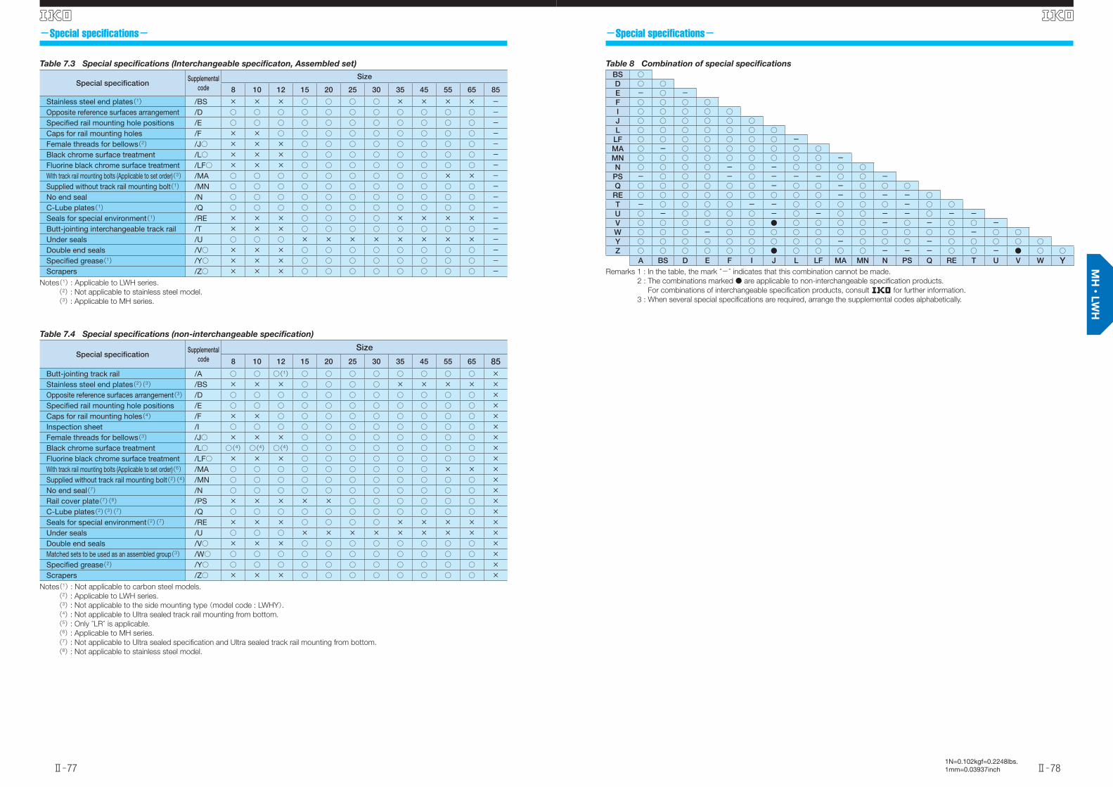
Table 8 Combination of special specifi cations
BS ○D ○ ○E - ○ -F ○ ○ ○ ○I ○ ○ ○ ○ ○J ○ ○ ○ ○ ○ ○L ○ ○ ○ ○ ○ ○ ○
LF ○ ○ ○ ○ ○ ○ ○ -MA ○ - ○ ○ ○ ○ ○ ○ ○MN ○ ○ ○ ○ ○ ○ ○ ○ ○ -N ○ ○ ○ ○ - ○ - ○ ○ ○ ○
PS - ○ ○ ○ - ○ - - - ○ ○ -Q ○ ○ ○ ○ ○ ○ - ○ ○ - ○ ○ ○
RE ○ ○ ○ ○ ○ ○ ○ ○ ○ - ○ - - ○T - ○ ○ ○ ○ - - ○ ○ ○ ○ ○ - ○ ○U ○ - ○ ○ ○ ○ - ○ - ○ ○ - - ○ - -V ○ ○ ○ ○ ○ ○ ● ○ ○ ○ ○ - ○ - ○ ○ -W ○ ○ ○ - ○ ○ ○ ○ ○ ○ ○ ○ ○ ○ ○ - ○ ○Y ○ ○ ○ ○ ○ ○ ○ ○ ○ - ○ ○ ○ - ○ ○ ○ ○ ○Z ○ ○ ○ ○ ○ ○ ● ○ ○ ○ ○ - - - ○ ○ - ● ○ ○
A BS D E F I J L LF MA MN N PS Q RE T U V W YRemarks 1 : In the table, the mark “-” indicates that this combination cannot be made.
2 : The combinations marked ● are applicable to non-interchangeable specifi cation products.
For combinations of interchangeable specifi cation products, consult R for further information.
3 : When several special specifi cations are required, arrange the supplemental codes alphabetically.
Table 7.3 Special specifi cations (Interchangeable specifi caton, Assembled set)
Special specifi cationSupplemental
code
Size
8 10 12 15 20 25 30 35 45 55 65 85
Stainless steel end plates(1) /BS × × × ○ ○ ○ ○ × × × × -Opposite reference surfaces arrangement /D ○ ○ ○ ○ ○ ○ ○ ○ ○ ○ ○ -Specifi ed rail mounting hole positions /E ○ ○ ○ ○ ○ ○ ○ ○ ○ ○ ○ -Caps for rail mounting holes /F × × ○ ○ ○ ○ ○ ○ ○ ○ ○ -Female threads for bellows(2) /J○ × × × ○ ○ ○ ○ ○ ○ ○ ○ -Black chrome surface treatment /L○ × × × ○ ○ ○ ○ ○ ○ ○ ○ -Fluorine black chrome surface treatment /LF○ × × × ○ ○ ○ ○ ○ ○ ○ ○ -With track rail mounting bolts (Applicable to set order)(3) /MA ○ ○ ○ ○ ○ ○ ○ ○ ○ × × -Supplied without track rail mounting bolt(1) /MN ○ ○ ○ ○ ○ ○ ○ ○ ○ ○ ○ -No end seal /N ○ ○ ○ ○ ○ ○ ○ ○ ○ ○ ○ -C-Lube plates(1) /Q ○ ○ ○ ○ ○ ○ ○ ○ ○ ○ ○ -Seals for special environment(1) /RE × × × ○ ○ ○ ○ × × × × -Butt-jointing interchangeable track rail /T × × × ○ ○ ○ ○ ○ ○ ○ ○ -Under seals /U ○ ○ ○ × × × × × × × × -Double end seals /V○ × × × ○ ○ ○ ○ ○ ○ ○ ○ -Specifi ed grease(1) /Y○ × × × ○ ○ ○ ○ ○ ○ ○ ○ -Scrapers /Z○ × × × ○ ○ ○ ○ ○ ○ ○ ○ -
Notes(1) : Applicable to LWH series.
(2) : Not applicable to stainless steel model.
(3) : Applicable to MH series.
Table 7.4 Special specifi cations (non-interchangeable specifi cation)
Special specifi cationSupplemental
code
Size
8 10 12 15 20 25 30 35 45 55 65 85Butt-jointing track rail /A ○ ○ ○(1) ○ ○ ○ ○ ○ ○ ○ ○ ×Stainless steel end plates(2)(3) /BS × × × ○ ○ ○ ○ × × × × ×Opposite reference surfaces arrangement(3) /D ○ ○ ○ ○ ○ ○ ○ ○ ○ ○ ○ ×Specifi ed rail mounting hole positions /E ○ ○ ○ ○ ○ ○ ○ ○ ○ ○ ○ ×Caps for rail mounting holes(4) /F × × ○ ○ ○ ○ ○ ○ ○ ○ ○ ×Inspection sheet /I ○ ○ ○ ○ ○ ○ ○ ○ ○ ○ ○ ×Female threads for bellows(3) /J○ × × × ○ ○ ○ ○ ○ ○ ○ ○ ×Black chrome surface treatment /L○ ○(4) ○(4) ○(4) ○ ○ ○ ○ ○ ○ ○ ○ ×Fluorine black chrome surface treatment /LF○ × × × ○ ○ ○ ○ ○ ○ ○ ○ ×With track rail mounting bolts (Applicable to set order)(6) /MA ○ ○ ○ ○ ○ ○ ○ ○ ○ × × ×Supplied without track rail mounting bolt(2)(4) /MN ○ ○ ○ ○ ○ ○ ○ ○ ○ ○ ○ ×No end seal(7) /N ○ ○ ○ ○ ○ ○ ○ ○ ○ ○ ○ ×Rail cover plate(7)(8) /PS × × × × × ○ ○ ○ ○ ○ ○ ×C-Lube plates(2)(3)(7) /Q ○ ○ ○ ○ ○ ○ ○ ○ ○ ○ ○ ×Seals for special environment(2)(7) /RE × × × ○ ○ ○ ○ × × × × ×Under seals /U ○ ○ ○ × × × × × × × × ×Double end seals /V○ × × × ○ ○ ○ ○ ○ ○ ○ ○ ×Matched sets to be used as an assembled group(3) /W○ ○ ○ ○ ○ ○ ○ ○ ○ ○ ○ ○ ×Specifi ed grease(2) /Y○ ○ ○ ○ ○ ○ ○ ○ ○ ○ ○ ○ ×Scrapers /Z○ × × × ○ ○ ○ ○ ○ ○ ○ ○ ×
Notes(1) : Not applicable to carbon steel models.
(2) : Applicable to LWH series.
(3) : Not applicable to the side mounting type (model code : LWHY).(4) : Not applicable to Ultra sealed track rail mounting from bottom.
(5) : Only “LR” is applicable.
(6) : Applicable to MH series.
(7) : Not applicable to Ultra sealed specifi cation and Ultra sealed track rail mounting from bottom.
(8) : Not applicable to stainless steel model.
英_Ⅱ_065-084特長H.indd 77-78 11.6.2 10:27:29 AM
1N=0.102kgf=0.2248lbs.1mm=0.03937inchⅡ̶79
S
Ⅱ̶80
S
-Special specifi cations--Special specifi cations-
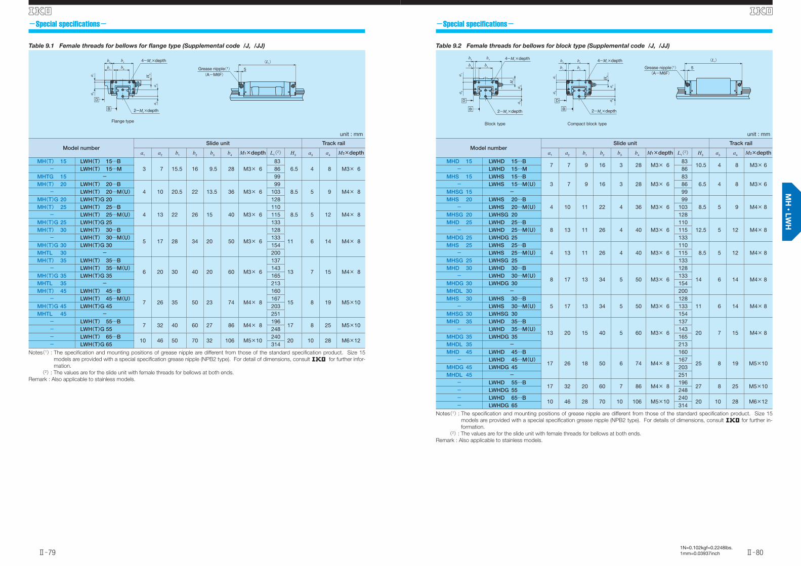
Table 9.1 Female threads for bellows for fl ange type (Supplemental code /J, /JJ)
unit : mm
Model numberSlide unit Track rail
a1 a2 b1 b2 b3 b4 M1×depth L1(2) H3 a3 a4 M2×depth
MH(T) 15 LWH(T) 15…B 3 7 15.5 16 9.5 28 M3× 6
836.5 4 8 M3× 6- LWH(T) 15…M 86
MHTG 15 - 99MH(T) 20 LWH(T) 20…B
4 10 20.5 22 13.5 36 M3× 6 99
8.5 5 9 M4× 8- LWH(T) 20…M(U) 103MH(T)G 20 LWH(T)G 20 128MH(T) 25 LWH(T) 25…B
4 13 22 26 15 40 M3× 6110
8.5 5 12 M4× 8- LWH(T) 25…M(U) 115MH(T)G 25 LWH(T)G 25 133MH(T) 30 LWH(T) 30…B
5 17 28 34 20 50 M3× 6
128
11 6 14 M4× 8- LWH(T) 30…M(U) 133
MH(T)G 30 LWH(T)G 30 154MHTL 30 - 200MH(T) 35 LWH(T) 35…B
6 20 30 40 20 60 M3× 6
137
13 7 15 M4× 8- LWH(T) 35…M(U) 143
MH(T)G 35 LWH(T)G 35 165MHTL 35 - 213MH(T) 45 LWH(T) 45…B
7 26 35 50 23 74 M4× 8
160
15 8 19 M5×10- LWH(T) 45…M(U) 167
MH(T)G 45 LWH(T)G 45 203MHTL 45 - 251
- LWH(T) 55…B 7 32 40 60 27 86 M4× 8
19617 8 25 M5×10
- LWH(T)G 55 248- LWH(T) 65…B
10 46 50 70 32 106 M5×10240
20 10 28 M6×12- LWH(T)G 65 314
Notes(1) : The specifi cation and mounting positions of grease nipple are different from those of the standard specifi cation product. Size 15
models are provided with a special specifi cation grease nipple (NPB2 type). For detail of dimensions, consult R for further infor-
mation.
(2) : The values are for the slide unit with female threads for bellows at both ends.
Remark : Also applicable to stainless models.
(L1)
Grease nipple(1) 5(A-M6F)
a 3a 4
H3
2-M2×depth
Flange type
B
D
a 1a 2
b4b3
b1b2
4-M1×depth
Table 9.2 Female threads for bellows for block type (Supplemental code /J, /JJ)
unit : mm
Model numberSlide unit Track rail
a1 a2 b1 b2 b3 b4 M1×depth L1(2) H3 a3 a4 M2×depth
MHD 15 LWHD 15…B 7 7 9 16 3 28 M3× 6
8310.5 4 8 M3× 6
- LWHD 15…M 86MHS 15 LWHS 15…B
3 7 9 16 3 28 M3× 6 83
6.5 4 8 M3× 6- LWHS 15…M(U) 86MHSG 15 - 99MHS 20 LWHS 20…B
4 10 11 22 4 36 M3× 6 99
8.5 5 9 M4× 8- LWHS 20…M(U) 103MHSG 20 LWHSG 20 128MHD 25 LWHD 25…B
8 13 11 26 4 40 M3× 6110
12.5 5 12 M4× 8- LWHD 25…M(U) 115MHDG 25 LWHDG 25 133MHS 25 LWHS 25…B
4 13 11 26 4 40 M3× 6110
8.5 5 12 M4× 8- LWHS 25…M(U) 115MHSG 25 LWHSG 25 133MHD 30 LWHD 30…B
8 17 13 34 5 50 M3× 6
128
14 6 14 M4× 8- LWHD 30…M(U) 133
MHDG 30 LWHDG 30 154MHDL 30 - 200MHS 30 LWHS 30…B
5 17 13 34 5 50 M3× 6128
11 6 14 M4× 8- LWHS 30…M(U) 133MHSG 30 LWHSG 30 154MHD 35 LWHD 35…B
13 20 15 40 5 60 M3× 6
137
20 7 15 M4× 8- LWHD 35…M(U) 143
MHDG 35 LWHDG 35 165MHDL 35 - 213MHD 45 LWHD 45…B
17 26 18 50 6 74 M4× 8
160
25 8 19 M5×10- LWHD 45…M(U) 167
MHDG 45 LWHDG 45 203MHDL 45 - 251
- LWHD 55…B17 32 20 60 7 86 M4× 8
19627 8 25 M5×10
- LWHDG 55 248- LWHD 65…B
10 46 28 70 10 106 M5×10240
20 10 28 M6×12- LWHDG 65 314
Notes(1) : The specifi cation and mounting positions of grease nipple are different from those of the standard specifi cation product. Size 15
models are provided with a special specifi cation grease nipple (NPB2 type). For details of dimensions, consult R for further in-
formation.
(2) : The values are for the slide unit with female threads for bellows at both ends.
Remark : Also applicable to stainless models.
b4b3
b1 b2
a 1a 2
a 3a 4
H3
2-M2×depth
4-M1×depth
Block type
D
B
b4b3
b1 b2
4-M1×depth
a 1a 2
a 3a 4
H3
2-M2×depth
Compact block type
(L1)
Grease nipple(1) 5(A-M6F)
B
D
英_Ⅱ_065-084特長H.indd 79-80 11.6.2 10:27:31 AM
1N=0.102kgf=0.2248lbs.1mm=0.03937inchⅡ̶81
S
Ⅱ̶82
S
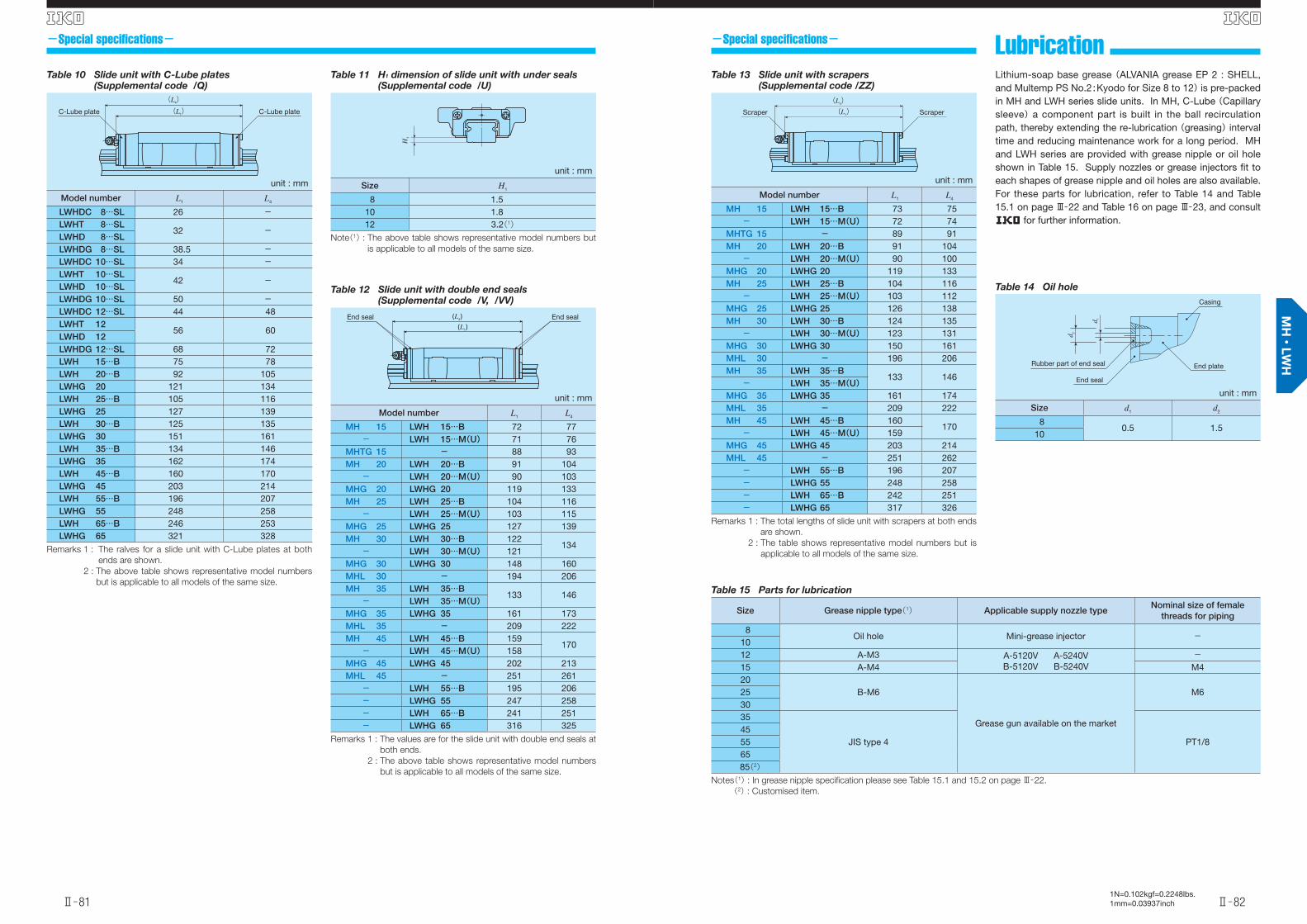
-Special specifi cations- -Special specifi cations- Lubrication Lithium-soap base grease (ALVANIA grease EP 2 : SHELL, and Multemp PS No.2 : Kyodo for Size 8 to 12) is pre-packed in MH and LWH series slide units. In MH, C-Lube (Capillary sleeve) a component part is built in the ball recirculation path, thereby extending the re-lubrication (greasing) interval time and reducing maintenance work for a long period. MH and LWH series are provided with grease nipple or oil hole shown in Table 15. Supply nozzles or grease injectors fi t to each shapes of grease nipple and oil holes are also available. For these parts for lubrication, refer to Table 14 and Table 15.1 on page Ⅲ̶22 and Table 16 on page Ⅲ̶23, and consult R for further information.
Table 11 H1 dimension of slide unit with under seals(Supplemental code /U)
unit : mm
Size H1
8 1.510 1.812 3.2(1)
Note(1) : The above table shows representative model numbers but
is applicable to all models of the same size.
H1
Table 12 Slide unit with double end seals(Supplemental code /V, /VV)
unit : mm
Model number L1 L4
MH 15 LWH 15…B 72 77- LWH 15…M(U) 71 76
MHTG 15 - 88 93MH 20 LWH 20…B 91 104
- LWH 20…M(U) 90 103MHG 20 LWHG 20 119 133MH 25 LWH 25…B 104 116
- LWH 25…M(U) 103 115MHG 25 LWHG 25 127 139MH 30 LWH 30…B 122
134- LWH 30…M(U) 121
MHG 30 LWHG 30 148 160MHL 30 - 194 206MH 35 LWH 35…B
133 146- LWH 35…M(U)
MHG 35 LWHG 35 161 173MHL 35 - 209 222MH 45 LWH 45…B 159
170- LWH 45…M(U) 158
MHG 45 LWHG 45 202 213MHL 45 - 251 261
- LWH 55…B 195 206- LWHG 55 247 258- LWH 65…B 241 251- LWHG 65 316 325
Remarks 1 : The values are for the slide unit with double end seals at
both ends.
2 : The above table shows representative model numbers
but is applicable to all models of the same size.
End sealEnd seal(L1)(L4)
Table 10 Slide unit with C-Lube plates(Supplemental code /Q)
unit : mm
Model number L1 L4
LWHDC 8…SL 26 -LWHT 8…SL
32 -LWHD 8…SLLWHDG 8…SL 38.5 -LWHDC 10…SL 34 -LWHT 10…SL
42 -LWHD 10…SLLWHDG 10…SL 50 -LWHDC 12…SL 44 48LWHT 12
56 60LWHD 12LWHDG 12…SL 68 72LWH 15…B 75 78LWH 20…B 92 105LWHG 20 121 134LWH 25…B 105 116LWHG 25 127 139LWH 30…B 125 135LWHG 30 151 161LWH 35…B 134 146LWHG 35 162 174LWH 45…B 160 170LWHG 45 203 214LWH 55…B 196 207LWHG 55 248 258LWH 65…B 246 253LWHG 65 321 328
Remarks 1 : The ralves for a slide unit with C-Lube plates at both
ends are shown.
2 : The above table shows representative model numbers
but is applicable to all models of the same size.
C-Lube plateC-Lube plate
(L4)(L1)
Table 14 Oil hole
unit : mm
Size d1 d2
80.5 1.5
10
d 2
d 1
End seal
End plate
Casing
Rubber part of end seal
Table 15 Parts for lubrication
Size Grease nipple type(1) Applicable supply nozzle typeNominal size of female
threads for piping
8Oil hole Mini-grease injector -
1012 A-M3 A-5120V A-5240V
B-5120V B-5240V-
15 A-M4 M420
B-M6
Grease gun available on the market
M6253035
JIS type 4 PT1/8455565
85(2)Notes(1) : In grease nipple specifi cation please see Table 15.1 and 15.2 on page Ⅲ̶22.
(2) : Customised item.
Table 13 Slide unit with scrapers(Supplemental code /ZZ)
unit : mm
Model number L1 L4
MH 15 LWH 15…B 73 75- LWH 15…M(U) 72 74
MHTG 15 - 89 91MH 20 LWH 20…B 91 104
- LWH 20…M(U) 90 100MHG 20 LWHG 20 119 133MH 25 LWH 25…B 104 116
- LWH 25…M(U) 103 112MHG 25 LWHG 25 126 138MH 30 LWH 30…B 124 135
- LWH 30…M(U) 123 131MHG 30 LWHG 30 150 161MHL 30 - 196 206MH 35 LWH 35…B
133 146- LWH 35…M(U)
MHG 35 LWHG 35 161 174MHL 35 - 209 222MH 45 LWH 45…B 160
170- LWH 45…M(U) 159
MHG 45 LWHG 45 203 214MHL 45 - 251 262
- LWH 55…B 196 207- LWHG 55 248 258- LWH 65…B 242 251- LWHG 65 317 326
Remarks 1 : The total lengths of slide unit with scrapers at both ends
are shown.
2 : The table shows representative model numbers but is
applicable to all models of the same size.
ScraperScraper
(L4)(L1)
英_Ⅱ_065-084特長H.indd 81-82 11.6.2 10:27:33 AM
1N=0.102kgf=0.2248lbs.1mm=0.03937inchⅡ̶83
S
Ⅱ̶84
S
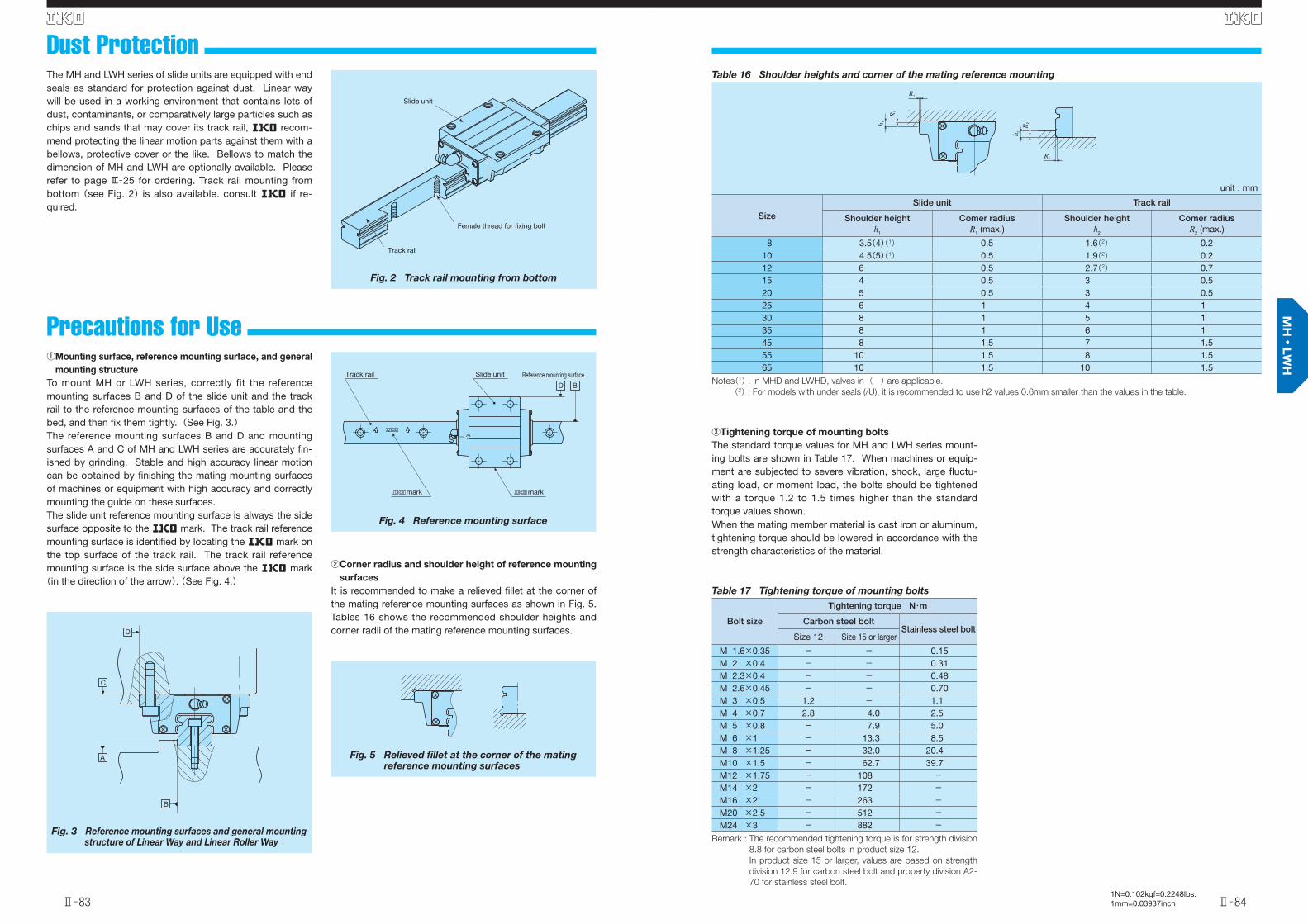
Dust Protection
Precautions for Use
The MH and LWH series of slide units are equipped with end seals as standard for protection against dust. Linear way will be used in a working environment that contains lots of dust, contaminants, or comparatively large particles such as chips and sands that may cover its track rail, R recom-mend protecting the linear motion parts against them with a bellows, protective cover or the like. Bellows to match the dimension of MH and LWH are optionally available. Please refer to page Ⅲ̶25 for ordering. Track rail mounting from bottom (see Fig. 2) is also available. consult R if re-quired.
① Mounting surface, reference mounting surface, and general
mounting structure
To mount MH or LWH series, correctly fit the reference mounting surfaces B and D of the slide unit and the track rail to the reference mounting surfaces of the table and the bed, and then fi x them tightly. (See Fig. 3.)The reference mounting surfaces B and D and mounting surfaces A and C of MH and LWH series are accurately fi n-ished by grinding. Stable and high accuracy linear motion can be obtained by fi nishing the mating mounting surfaces of machines or equipment with high accuracy and correctly mounting the guide on these surfaces. The slide unit reference mounting surface is always the side surface opposite to the R mark. The track rail reference mounting surface is identifi ed by locating the R mark on the top surface of the track rail. The track rail reference mounting surface is the side surface above the R mark (in the direction of the arrow). (See Fig. 4.)
②Corner radius and shoulder height of reference mounting
surfaces
It is recommended to make a relieved fi llet at the corner of the mating reference mounting surfaces as shown in Fig. 5. Tables 16 shows the recommended shoulder heights and corner radii of the mating reference mounting surfaces.
③Tightening torque of mounting bolts
The standard torque values for MH and LWH series mount-ing bolts are shown in Table 17. When machines or equip-ment are subjected to severe vibration, shock, large fl uctu-ating load, or moment load, the bolts should be tightened with a torque 1.2 to 1.5 times higher than the standard torque values shown.When the mating member material is cast iron or aluminum, tightening torque should be lowered in accordance with the strength characteristics of the material.
Fig. 3 Reference mounting surfaces and general mounting structure of Linear Way and Linear Roller Way
B
A
C
D
Fig. 4 Reference mounting surface
Reference mounting surface
BD
mark
Track rail Slide unit
mark
マーク
Fig. 5 Relieved fi llet at the corner of the matingreference mounting surfaces
Table 16 Shoulder heights and corner of the mating reference mounting
unit : mm
Size
Slide unit Track rail
Shoulder heighth1
Comer radiusR1 (max.)
Shoulder heighth2
Comer radiusR2 (max.)
8 3.5(4)(1) 0.5 1.6(2) 0.210 4.5(5)(1) 0.5 1.9(2) 0.212 6 0.5 2.7(2) 0.715 4 0.5 3 0.520 5 0.5 3 0.525 6 1 4 130 8 1 5 135 8 1 6 145 8 1.5 7 1.555 10 1.5 8 1.565 10 1.5 10 1.5
Notes(1) : In MHD and LWHD, valves in ( ) are applicable.
(2) : For models with under seals (/U), it is recommended to use h2 values 0.6mm smaller than the values in the table.
h 1
h 2
R1
R2
R2
R1
Table 17 Tightening torque of mounting bolts
Bolt size
Tightening torque N・m
Carbon steel bolt Stainless steel bolt
Size 12 Size 15 or larger
M 1.6×0.35 - - 0.15M 2 ×0.4 - - 0.31M 2.3×0.4 - - 0.48M 2.6×0.45 - - 0.70M 3 ×0.5 1.2 - 1.1M 4 ×0.7 2.8 4.0 2.5M 5 ×0.8 - 7.9 5.0M 6 ×1 - 13.3 8.5M 8 ×1.25 - 32.0 20.4M10 ×1.5 - 62.7 39.7M12 ×1.75 - 108 -M14 ×2 - 172 -M16 ×2 - 263 -M20 ×2.5 - 512 -M24 ×3 - 882 -
Remark : The recommended tightening torque is for strength division
8.8 for carbon steel bolts in product size 12.
In product size 15 or larger, values are based on strength
division 12.9 for carbon steel bolt and property division A2-
70 for stainless steel bolt.
Fig. 2 Track rail mounting from bottom
Female thread for fixing bolt
Track rail
Slide unit
英_Ⅱ_065-084特長H.indd 83-84 11.6.2 10:27:35 AM
C-Lube Linear Way MH
Ⅱ̶85
S
Ⅱ̶86
S
1N=0.102kgf=0.2248lbs.1mm=0.03937inch
Model number
Inte
rcha
ngea
ble Mass(Reference) Dimension of
assemblymm
Dimension of slide unitmm
Dimension of track railmm
Recommended(3) mounting
bolt for track rail
Basic(4) dynamic
load rating
Basic(4)static
load rating
Static moment rating(4)
MHLWH
(Non C-Lube)
Slide unit
kg
Track rail
kg/mH H1 N W2 W3 W4 L1 L2 L3 L4 d1 H2 H3 W H4 d3 d4 h M h1(2) h2 E F
mm
Bolt size×length
C
N
C0
N
T0
N・m
TX
N・m
TY
N・m
MH 15 ○
0.22 1.47 24 4.5 16 47 38 4.5 66 30
44.2
69 4.5 7 4.5 15 154.5 8 6 - - -
30 60M4×16
11 600 13 400 112 95.6556
95.6556
LWH 15…B ○
44.6- LWH 15…SL ○
- LWH 15…M* -
- LWH 15…MU* - - - - M 6 12 9 -
MH 20 ○
0.48
2.56 30 5 21.5 63 53 5
83
40
56
94
6 10 5.5 20 18
6 9.5 8.5 - - -
30 60
M5×1818 100 21 100 232 195
1 090195
1 090
LWH 20…B ○
57.2- LWH 20…SL ○
- LWH 20…M* -
- LWH 20…MU* - - - - M 8 13.5 9.5 -
MHG 20 ○0.71 112
84.8122 6 9.5 8.5 - - - M5×18 24 100 31 700 349 421
2 140421
2 140LWHG 20 ○ 86
MH 25 ○
0.70
3.50 36 6.5 23.5 70 57 6.5
95
45
63.9
105
7 10 6.5 23 22
7 11 9 - - -
30 60
M6×2225 200 28 800 362 309
1 690309
1 690
LWH 25…B ○
64.7- LWH 25…SL ○
- LWH 25…M* -
- LWH 25…MU* - - - - M10 18 13 -
MHG 25 ○0.93 118
86.6128 7 11 9 - - - M6×22 30 800 38 300 483 533
2 740533
2 740LWHG 25 ○ 87.4
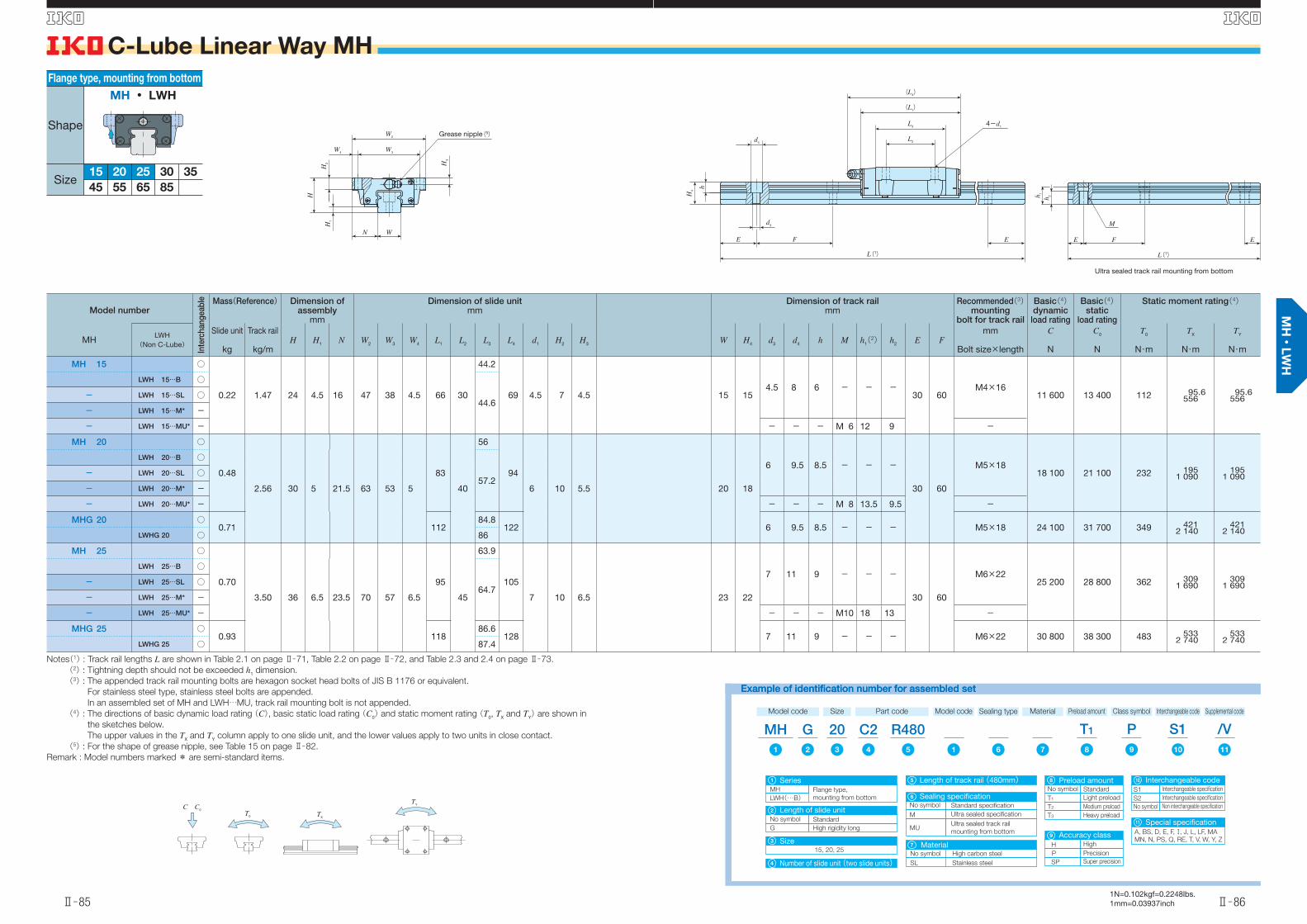
Notes(1) : Track rail lengths L are shown in Table 2.1 on page Ⅱ̶71, Table 2.2 on page Ⅱ̶72, and Table 2.3 and 2.4 on page Ⅱ̶73.
(2) : Tightning depth should not be exceeded h1 dimension.
(3) : The appended track rail mounting bolts are hexagon socket head bolts of JIS B 1176 or equivalent.
For stainless steel type, stainless steel bolts are appended.
In an assembled set of MH and LWH…MU, track rail mounting bolt is not appended.
(4) : The directions of basic dynamic load rating (C), basic static load rating (C0) and static moment rating (T0, TX and TY) are shown in
the sketches below.
The upper values in the TX and TY column apply to one slide unit, and the lower values apply to two units in close contact.
(5) : For the shape of grease nipple, see Table 15 on page Ⅱ̶82.
Remark : Model numbers marked * are semi-standard items.
Flange type, mounting from bottom
Shape
Size15 2520
655545
3530
85
MH ・ LWH
Example of identification number for assembled setExample of identification number for assembled set
Model code
MHSize Part code
R480C220
A, BS, D, E, F, , J, L, LF, MA
MN, N, PS, Q, RE, T, V, W, Y, Z
15, 20, 25
G
MH Flange type,
mounting from bottomLWH(…B)
No symbol Standard
G High rigidity long
Preload amount Class symbol Supplemental code
T1 /VPInterchangeable code
S1MaterialModel code Sealing type
1 12 9876543 1110
No symbol
M Ultra sealed specification
Standard specification
MUUltra sealed track rail
mounting from bottom
No symbol
T1 Light preload
Standard
T2 Medium preload
T3 Heavy preload
H
P Precision
High
SP Super precision
No symbol
SL Stainless steel
High carbon steel
S1
S2 Interchangeable specification
Interchangeable specification
No symbol Non interchangeable specification
Number of slide unit (two slide units)
Special specification
Size
Series
Length of slide unit
Sealing specification
1
4
3
2
Length of track rail (480mm)5 Preload amount8
6
Accuracy class 9
11
Material7
Interchangeable code10
C C0
TXT0
TY
W2
W3
H3
H2
H1
H
W4
N W
L(1)
d4
d3
H4
h
F EE
4-d1
L2
L3
(L1)
(L4)
h 1
h 2
E F E
M
L(1)
Ultra sealed track rail mounting from bottom
Grease nipple(5)
英_Ⅱ_085_110寸法MH.indd 85-86 11.6.2 10:28:38 AM
C-Lube Linear Way MH
Ⅱ̶87
S
Ⅱ̶88
S
1N=0.102kgf=0.2248lbs.1mm=0.03937inch
Model number
Inte
rcha
ngea
ble Mass(Reference) Dimension of
assemblymm
Dimension of slide unitmm
Dimension of track railmm
Recommended(3) mounting
bolt for track rail
Basic(4) dynamic
load rating
Basic(4)static
load rating
Static moment rating(4)
MHLWH
(Non C-Lube)
Slide unit
kg
Track rail
kg/mH H1 N W2 W3 W4 L1 L2 L3 L4 d1 H2 H3 W H4 d3 d4 h M h1(2) h2 E F
mm
Bolt size×length
C
N
C0
N
T0
N・m
TX
N・m
TY
N・m
MH 30 ○
1.28
4.82 42
9
31 90 72 9
113
52
80.6 123
9 10 8 28 25
9 14 12 - - -
40 80
M 8×2835 400 40 700 623 536
2 820536
2 820
LWH 30…B ○
7- LWH 30…SL ○
- LWH 30…M* -
- LWH 30…MU* - - - - M12 20 13 -
MHG 30 ○1.69
9139 106.6 149 9 14 12 - - - M 8×28 42 700 53 200 814 894
4 460894
4 460LWHG 30 ○ 7
MH 35 ○
1.79
6.85 48
10
33 100 82 9
123
62
86.2 135
9 13 10 34 28
9 14 12 - - -
40 80
M 8×2848 700 53 700 823 631
3 480579
3 190LWH 35…B ○
8- LWH 35…M* -
- LWH 35…MU* - - - - M12 23 16 -
MHG 35 ○2.35
10151 114 163 9 14 12 - - - M 8×28 59 500 71 600 1 100 1 090
5 5701 0005 110LWHG 35 ○ 8
MH 45 ○
3.17
10.7 60
13
37.5 120 100 10
147
80
103.4 158
11 15 13 45 34
14 20 17 - - -
52.5 105
M12×3574 600 80 200 1 610 1 150
6 1901 0605 690
LWH 45…B ○
10- LWH 45…M* -
- LWH 45…MU* - - - - M16 29 17 -
MHG 45 ○4.34
13190 146.6 201 14 20 17 - - - M12×35 95 200 114 000 2 280 2 240
11 1002 050
10 200LWHG 45 ○ 14
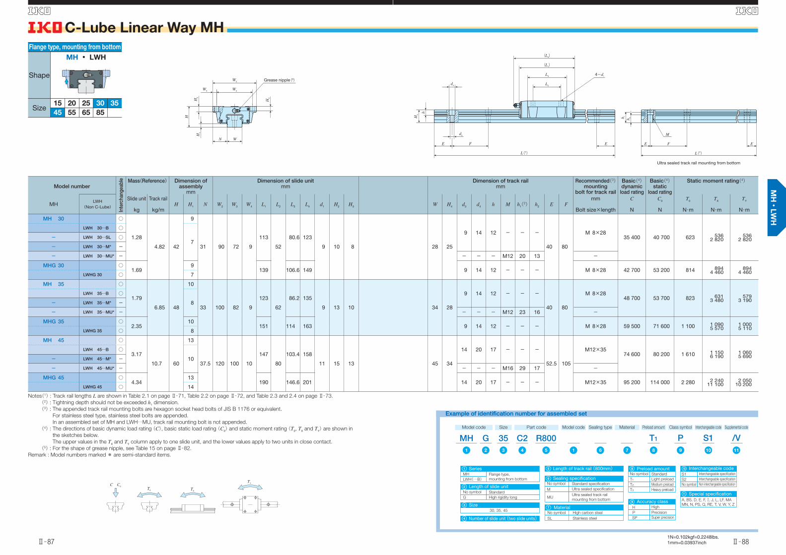
Notes(1) : Track rail lengths L are shown in Table 2.1 on page Ⅱ̶71, Table 2.2 on page Ⅱ̶72, and Table 2.3 and 2.4 on page Ⅱ̶73.
(2) : Tightning depth should not be exceeded h1 dimension.
(3) : The appended track rail mounting bolts are hexagon socket head bolts of JIS B 1176 or equivalent.
For stainless steel type, stainless steel bolts are appended.
In an assembled set of MH and LWH…MU, track rail mounting bolt is not appended.
(4) : The directions of basic dynamic load rating (C), basic static load rating (C0) and static moment rating (T0, TX and TY) are shown in
the sketches below.
The upper values in the TX and TY column apply to one slide unit, and the lower values apply to two units in close contact.
(5) : For the shape of grease nipple, see Table 15 on page Ⅱ̶82.
Remark : Model numbers marked * are semi-standard items.
Flange type, mounting from bottom
Shape
Size15 2520
655545
3530
85
MH ・ LWH
Example of identification number for assembled setExample of identification number for assembled set
Model code
MHSize Part code
R800C235
Number of slide unit (two slide units)
Special specificationA, BS, D, E, F, , J, L, LF, MA
MN, N, PS, Q, RE, T, V, W, Y, ZSize30, 35, 45
GPreload amount Class symbol Supplemental code
T1 /VPInterchangeable code
S1MaterialModel code
1 12 9876543 1110
4
3
Length of track rail (800mm)5
11
MH Flange type,
mounting from bottomLWH(…B)
No symbol Standard
G High rigidity long
Series
Length of slide unit
1
2
No symbol
SL Stainless steel
High carbon steel
Material7
No symbol
T1 Light preload
Standard
T2 Medium preload
T3 Heavy preload
Preload amount8
H
P Precision
High
SP Super precision
Accuracy class 9
S1
S2 Interchangeable specification
Interchangeable specification
No symbol Non interchangeable specification
Interchangeable code10
Sealing type
No symbol
M Ultra sealed specification
Standard specification
MUUltra sealed track rail
mounting from bottom
Sealing specification6
C C0
TXT0
TY
W3W4
H2
H
H1
H3
WN
W2
4-d1
d4
d3
FE
h
H4
E
L2
L3
(L1)
(L4)
L(1)
h 1
h 2
E F E
M
L(1)
Ultra sealed track rail mounting from bottom
Grease nipple(5)
英_Ⅱ_085_110寸法MH.indd 87-88 11.6.2 10:28:40 AM
C-Lube Linear Way MH
Ⅱ̶89
S
Ⅱ̶90
S
1N=0.102kgf=0.2248lbs.1mm=0.03937inch
Model number
Inte
rcha
ngea
ble Mass(Reference) Dimension of
assemblymm
Dimension of slide unitmm
Dimension of track railmm
Recommended(2) mounting
bolt for track rail
Basic(3) dynamic
load rating
Basic(3)static
load rating
Static moment rating(3)
MHLWH
(Non C-Lube)
Slide unit
kg
Track rail
kg/mH H1 N W2 W3 W4 L1 L2 L3 L4 d1 H2 H3 H5 W H4 d3 d4 h E F
mm
Bolt size×length
C
N
C0
N
T0
N・m
TX
N・m
TY
N・m
- LWH 55…B ○ 5.3015.5 70 13 43.5 140 116 12
18395
132 19414 17 14 - 53 41 16 23 20 60 120 M14×45
113 000 121 000 2 870 2 21011 600
2 03010 600
- LWHG 55 ○ 7.40 235 183.6 246 142 000 168 000 3 970 4 12020 200
3 78018 500
- LWH 65…B ○ 12.322.2 90 14 53.5 170 142 14
229110
164 23916 23 20 - 63 48 18 26 22 75 150 M16×50
176 000 184 000 5 180 4 13022 000
3 79020 200
- LWHG 65 ○ 17.6 303 238.8 313 229 000 269 000 7 560 8 53041 500
7 81038 100
- LWHG 85(4) - 25.9 34.6 110 16 65 215 185 15 318 140 240 - 18 30 22 15 85 58 26 39 30 90 180 M24×60 374 000 384 000 11 900 11 10055 100
11 10055 300
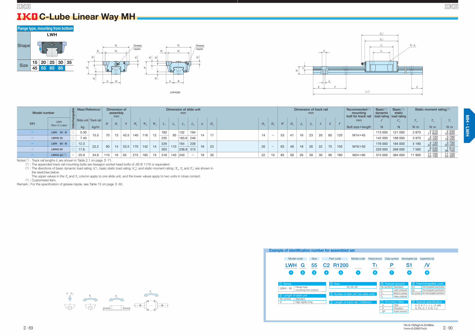
Notes(1) : Track rail lengths L are shown in Table 2.1 on page Ⅱ̶71.
(2) : The appended track rail mounting bolts are hexagon socket head bolts of JIS B 1176 or equivalent.
(3) : The directions of basic dynamic load rating (C), basic static load rating (C0) and static moment rating (T0, TX and TY) are shown in
the sketches below.
The upper values in the TX and TY column apply to one slide unit, and the lower values apply to two units in close contact.
(4) : Customised item.
Remark : For the specifi cation of grease nipple, see Table 15 on page Ⅱ̶82.
Example of identification number for assembled setExample of identification number for assembled set
Model code
LWHSize Part code
R1200C255G
LWH(…B)
SeriesFlange type,
mounting from bottom
Preload amount Class symbol Supplemental code
T1 /VPInterchangeable code
S1Model code
1 12 76543 98
1
Number of slide unit (two slide units)4
Size55, 65, 85
3
Length of track rail (1200mm)5 Special specificationA, D, E, F, , J, L, LF, MN
N, PS, Q, T, V, W, Y, Z
9
No symbol Standard
G High rigidity long
Length of slide unit2
No symbol
T1 Light preload
Standard
T2 Medium preload
T3 Heavy preload
Preload amount6
H
P Precision
High
SP Super precision
Accuracy class 7
S1
S2 Interchangeable specification
Interchangeable specification
No symbol Non interchangeable specification
Interchangeable code8
Flange type, mounting from bottom
Shape
Size15 2520
655545
3530
85
LWH
C C0
TXT0
TY
4-d1
d4
d3
FE
h
H4
E
L2
L3
(L1)
(L4)
L(1)
W3W4
H2
H
H1
H3
WN
W2
W3
N W
W4
H1
H2
H5
H3
H
W2
LWHG85
Greasenipple
Greasenipple
英_Ⅱ_085_110寸法MH.indd 89-90 11.6.2 10:28:42 AM

C-Lube Linear Way MH
Ⅱ̶91
S
Ⅱ̶92
S
1N=0.102kgf=0.2248lbs.1mm=0.03937inch
Model number
Inte
rcha
ngea
ble Mass(Reference) Dimension of
assemblymm
Dimension of slide unitmm
Dimension of track railmm
Recommended(4) mounting
bolt for track rail
Basic(5) dynamic
load rating
Basic(5)static
load rating
Static moment rating(5)
MHLWH
(Non C-Lube)
Slide unit
kg
Track rail
kg/mH H1 N W2 W3 W4 L1 L2 L3 L4 d1(2) M1 H2 H3 W H4 d3 d4 h M h1(3) h2 E F
mm
Bolt size×length
C
N
C0
N
T0
N・m
TX
N・m
TY
N・m
MHT 8…SL LWHT 8…SL ○ 0.015 0.32 10 2.1 8 24 19 2.5 24 10 15.3 - 1.9 M2.3 3.5 2 8 6 2.4 4.2 2.3 - - - 10 20 M2× 8 1 510 2 120 8.8 5.532.0
4.726.9
MHT 10…SL ○ 0.0310.47 12 2.4 10 30 24 3 32 12 21.4 - 2.6 M3 4.5 2.5 10 7 3.5 6 3.5 - - - 12.5 25 M3× 8 2 640 3 700 19.2 13.3
73.811.161.9LWHT 10…SL ○ 0.032
MHT 12 ○ 0.108
0.86 19 3.2 14 40 32 4 46 15 31.6 50 3.4 M4 6 4 12 10.5 3.5 6 4.5 - - - 20 40 M3×12 6 260 8 330 51.6 44.7237
37.5199
LWHT 12 ○ 0.11
MHT 12…SL ○ 0.108
LWHT 12…SL ○ 0.11
MHT 15 ○
0.221.47 24 4.5 16 47 38 4.5
6630
44.2
69 -M5 7 4.5 15 15
4.5 8 6 - - -
30 60
M4×1611 600 13 400 112 95.6
55695.6
556
LWHT 15…B ○ 44.6
MHT 15…SL ○ 44.2
LWHT 15…SL ○
44.6- LWHT 15…M* -
- LWHT 15…MU* - - - - M6 12 9 -
MHTG 15 ○ 0.29 82 60.1 85 4.4 4.5 8 6 - - - M4×16 14 400 18 300 153 172918
172918
Notes(1) : Track rail lengths L are shown in Table 2.1 on page Ⅱ̶71, Table 2.2 on page Ⅱ̶72, and Table 2.3 and 2.4 on page Ⅱ̶73.
(2) : In sizes 8 to 12 and MHTG15, they can be also mounted from the lower side.
(3) : Tightning depth should not be exceeded h1 dimension.
(4) : The appended track rail mounting bolts are hexagon socket head bolts of JIS B 1176 or equivalent.
For stainless steel type, stainless steel bolts are appended.
In an assembled set of MHT and LWHT…MU, track rail mounting bolt is not appended.
(5) : The directions of basic dynamic load rating (C), basic static load rating (C0) and static moment rating (T0, TX and TY) are shown in
the sketches below.
The upper values in the TX and TY column apply to one slide unit, and the lower values apply to two units in close contact.
(6) : In sizes 8 and 10, they are provided with an oil hole. For specifi cation, see Table 14 on page Ⅱ̶82.
For the shape of grease nipple, see Table 15 on page Ⅱ̶82.
Remark : Model numbers marked * are semi-standard items.
Flange type, mounting from top
Shape
Size8 1210
453530
15
55
25
85
20
65
MHT ・ LWHT
Example of identification number for assembled setExample of identification number for assembled set
Special specificationA, BS, D, E, F, , J, L, LF, MA
MN, N, Q, RE, T, U, V, W, Y, Z
11
Preload amount
No symbol
T1 Light preload
Standard
T2 Medium preload
T3 Heavy preload
8
T0 Clearance
H
P Precision
High
SP Super precision
Accuracy class 9
S1
S2 Interchangeable specification
Interchangeable specification
No symbol Non interchangeable specification
Interchangeable code10
Model code
MHTSize Part code
R900C215G
MHT
SeriesFlange type,
mounting from topLWHT(…B)
Preload amount Class symbol Supplemental code
T1 /VPInterchangeable code
S1Preload amountModel code
1 12 9876543 1110
1 Length of track rail (900mm)5
8, 10, 12, 15
No symbol Standard
G High rigidity long
Number of slide unit (two slide units)
Size
Length of slide unit
4
3
2
No symbol
SL Stainless steel
High carbon steel
Material7
Sealing type
No symbol
M Ultra sealed specification
Standard specification
MUUltra sealed track rail
mounting from bottom
Sealing specification6
C C0
TXT0
TY
W3W4
H2
H3
H1
H
d1
WN
W2
d4
d3
H4
h
FE E
4-M1
L2
L3
(L1)
(L4)
L(1)
MHT 08 …SL, LWHT 08 …SLMHT 10 …SL, LWHT 10 …SLMHT 12(…SL), LWHT 12(…SL)MHTG 15
h 1
h 2
E F E
M
L(1)
Ultra sealed track rail mounting from bottom
W3
H3
H2
H1
H
W4
N W
W2Greasenipple(6) Grease
nipple(6)
英_Ⅱ_085_110寸法MH.indd 91-92 11.6.2 10:28:43 AM
C-Lube Linear Way MH
Ⅱ̶93
S
Ⅱ̶94
S
1N=0.102kgf=0.2248lbs.1mm=0.03937inch
Model number
Inte
rcha
ngea
ble Mass(Reference) Dimension of
assemblymm
Dimension of slide unitmm
Dimension of track railmm
Recommended(3) mounting
bolt for track rail
Basic(4) dynamic
load rating
Basic(4)static
load rating
Static moment rating(4)
MHLWH
(Non C-Lube)
Slide unit
kg
Track rail
kg/mH H1 N W2 W3 W4 L1 L2 L3 L4 d1 M1 H2 H3 W H4 d3 d4 h M h1(2) h2 E F
mm
Bolt size×length
C
N
C0
N
T0
N・m
TX
N・m
TY
N・m
MHT 20 ○
0.48
2.56 30 5 21.5 63 53 5
83
40
56
94
- M6 10 5.5 20 18
6 9.5 8.5 - - -
30 60
M5×1818 100 21 100 232 195
1 090195
1 090
LWHT 20…B ○ 57.2
MHT 20…SL ○ 56
LWHT 20…SL ○
57.2- LWHT 20…M* -
- LWHT 20…MU* - - - - M 8 13.5 9.5 -
MHTG 20 ○0.71 112
84.8122 6 9.5 8.5 - - - M5×18 24 100 31 700 349 421
2 140421
2 140LWHTG 20 ○ 86
MHT 25 ○
0.70
3.50 36 6.5 23.5 70 57 6.5
95
45
63.9
105
- M8 10 6.5 23 22
7 11 9 - - -
30 60
M6×2225 200 28 800 362 309
1 690309
1 690
LWHT 25…B ○ 64.7
MHT 25…SL ○ 63.9
LWHT 25…SL ○
64.7- LWHT 25…M* -
- LWHT 25…MU* - - - - M10 18 13 -
MHTG 25 ○0.93 118
86.6128 7 11 9 - - - M6×22 30 800 38 300 483 533
2 740533
2 740LWHTG 25 ○ 87.4
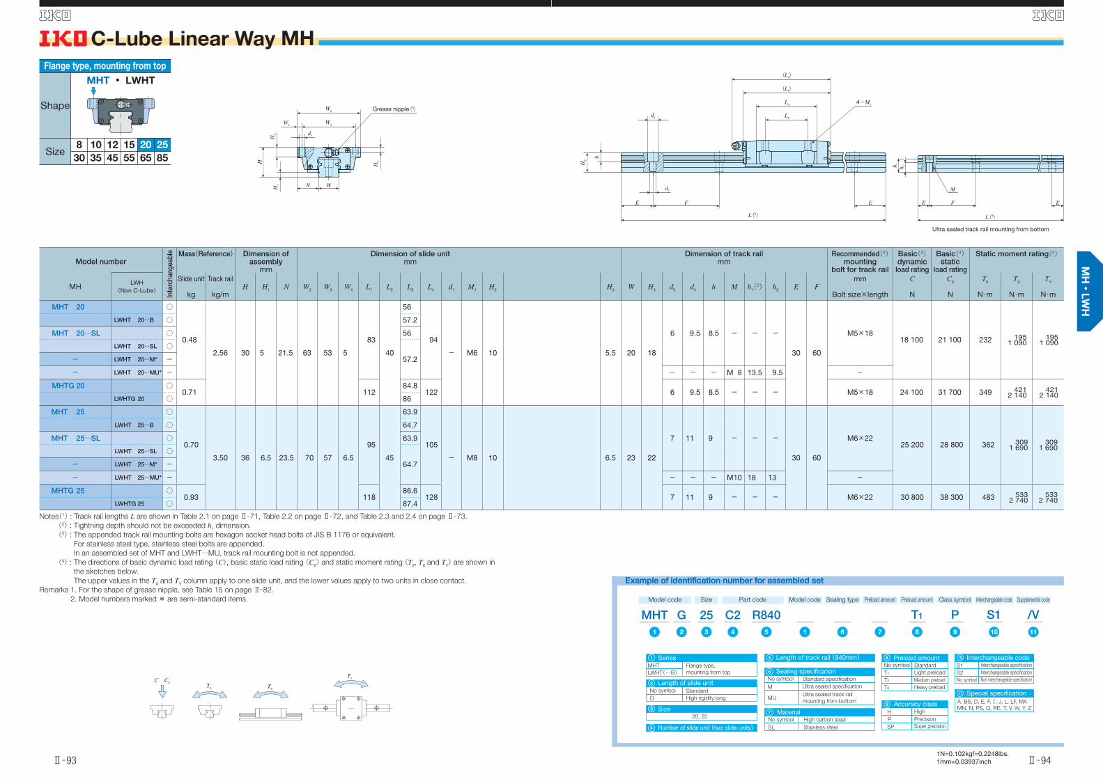
Notes(1) : Track rail lengths L are shown in Table 2.1 on page Ⅱ̶71, Table 2.2 on page Ⅱ̶72, and Table 2.3 and 2.4 on page Ⅱ̶73.
(2) : Tightning depth should not be exceeded h1 dimension.
(3) : The appended track rail mounting bolts are hexagon socket head bolts of JIS B 1176 or equivalent.
For stainless steel type, stainless steel bolts are appended.
In an assembled set of MHT and LWHT…MU, track rail mounting bolt is not appended.
(4) : The directions of basic dynamic load rating (C), basic static load rating (C0) and static moment rating (T0, TX and TY) are shown in
the sketches below.
The upper values in the TX and TY column apply to one slide unit, and the lower values apply to two units in close contact.
Remarks 1. For the shape of grease nipple, see Table 15 on page Ⅱ̶82.
2. Model numbers marked * are semi-standard items.
Flange type, mounting from top
Shape
Size8 1210
453530
15
55
25
85
20
65
MHT ・ LWHT
Example of identification number for assembled setExample of identification number for assembled set
Model code
MHTSize Part code
R840C225
Special specificationA, BS, D, E, F, , J, L, LF, MA
MN, N, PS, Q, RE, T, V, W, Y, Z
G
MHT
SeriesFlange type,
mounting from topLWHT(…B)
Preload amount Class symbol Supplemental code
T1 /VPInterchangeable code
S1Preload amountModel code
1 12 9876543 1110
1 Length of track rail (840mm)5
11
20, 25
No symbol Standard
G High rigidity long
Number of slide unit (two slide units)
Size
Length of slide unit
4
3
2
No symbol
SL Stainless steel
High carbon steel
Material7
No symbol
T1 Light preload
Standard
T2 Medium preload
T3 Heavy preload
H
P Precision
High
SP Super precision
Preload amount8
Accuracy class 9
S1
S2 Interchangeable specification
Interchangeable specification
No symbol Non interchangeable specification
Interchangeable code10
Sealing type
No symbol
M Ultra sealed specification
Standard specification
MUUltra sealed track rail
mounting from bottom
Sealing specification6
C C0
TXT0
TY
d1
W3
H3
H2
H1
H
W4
N W
W2
d4
d3
H4
h
FE E
L2
L3
(L1)
(L4)
L(1)
4-M1
h 1
h 2
E F E
M
L(1)
Ultra sealed track rail mounting from bottom
Grease nipple(5)
英_Ⅱ_085_110寸法MH.indd 93-94 11.6.2 10:28:45 AM

C-Lube Linear Way MH
Ⅱ̶95
S
Ⅱ̶96
S
1N=0.102kgf=0.2248lbs.1mm=0.03937inch
Model number
Inte
rcha
ngea
ble Mass(Reference) Dimension of
assemblymm
Dimension of slide unitmm
Dimension of track railmm
Recommended(4) mounting
bolt for track rail
Basic(5) dynamic
load rating
Basic(5)static
load rating
Static moment rating(5)
MHLWH
(Non C-Lube)
Slide unit
kg
Track rail
kg/mH H1 N W2 W3 W4 L1 L2 L3 L4 d1(2) M1 H2 H3 W H4 d3 d4 h M h1(3) h2 E F
mm
Bolt size×length
C
N
C0
N
T0
N・m
TX
N・m
TY
N・mMHT 30 ○
1.28
4.82 42
9
31 90 72 9
113
52
80.6 123-
M10 10 8 28 25
9 14 12 - - -
40 80
M 8×2835 400 40 700 623 536
2 820536
2 820
LWHT 30…B ○ 7MHT 30…SL ○ 9
LWHT 30…SL ○7- LWHT 30…M* -
- LWHT 30…MU* - - - - M12 20 13 -MHTG 30 ○
1.699
139 106.6 1499 14 12 - - - M 8×28
42 700 53 200 814 8944 460
8944 460LWHTG 30 ○ 7
MHTL 30 - ○ 2.30 8 185 152.2 194 8.5 54 400 75 100 1 150 1 7408 240
1 7408 240
MHT 35 ○
1.79
6.85 48
10
33 100 82 9
123
62
86.2 135-
M10 13 10 34 28
9 14 12 - - -
40 80
M 8×2848 700 53 700 823 631
3 480579
3 190LWHT 35…B ○
8- LWHT 35…M* -- LWHT 35…MU* - - - - M12 23 16 -
MHTG 35 ○2.35
10151 114 163
9 14 12 - - - M 8×2859 500 71 600 1 100 1 090
5 5701 0005 110LWHTG 35 ○ 8
MHTL 35 - ○ 3.24 9 199 162.2 211 8.5 76 700 103 000 1 580 2 20010 400
2 0109 490
MHT 45 ○
3.17
10.7 60
13
37.5 120 100 10
147
80
103.4 158-
M12 15 13 45 34
14 20 17 - - -
52.5 105
M12×3574 600 80 200 1 610 1 150
6 1901 0605 690
LWHT 45…B ○10- LWHT 45…M* -
- LWHT 45…MU* - - - - M16 29 17 -MHTG 45 ○
4.3413
190 146.6 20114 20 17 - - - M12×35
95 200 114 000 2 280 2 24011 100
2 05010 200LWHTG 45 ○ 10
MHTL 45 - ○ 5.70 12 238 194.8 249 10.5 114 000 147 000 2 960 3 68017 800
3 37016 300
Notes(1) : Track rail lengths L are shown in Table 2.1 on page Ⅱ̶71, Table 2.2 on page Ⅱ̶72, and Table 2.3 and 2.4 on page Ⅱ̶73.
(2) : MHTL30, MHTL35, and MHTL45 can be mounted also from bottom.
(3) : Tightning depth should not be exceeded h1 dimension.
(4) : The appended track rail mounting bolts are hexagon socket head bolts of JIS B 1176 or equivalent.
For stainless steel type, stainless steel bolts are appended.
In an assembled see of MH and LWHT…MU, track rail mounting bolt is not appended.
(5) : The directions of basic dynamic load rating (C), basic static load rating (C0) and static moment rating (T0, TX and TY) are shown in
the sketches below.
The upper values in the TX and TY column apply to one slide unit, and the lower values apply to two units in close contact.
(6) : For the shape of grease nipple, see Table 15 on page Ⅱ̶82.
Remark : Model numbers marked * are semi-standard items.
Flange type, mounting from top
Shape
Size8 1210
453530
15
55
25
85
20
65
MHT ・ LWHT
Example of identification number for assembled setExample of identification number for assembled set
Model code
MHTSize Part code
R1260C245
Number of slide unit (two slide units)
Special specificationA, BS, D, E, F, , J, L, LF, MA
MN, N, PS, Q, RE, T, V, W, Y, Z
Size30, 35, 45
G
MHT
SeriesFlange type,
mounting from topLWHT(…B)
No symbol
Length of slide unitStandard
G High rigidity long
Preload amount Class symbol Supplemental code
T1 /VPInterchangeable code
S1MaterialModel code
1 12 9876543 1110
1
4
3
2
Length of track rail (1260mm)5
11
L Extra High rigidity long
No symbol
SL Stainless steel
High carbon steel
Material7
No symbol
T1 Light preload
Standard
T2 Medium preload
T3 Heavy preload
Preload amount8
H
P Precision
High
SP Super precision
Accuracy class 9
S1
S2 Interchangeable specification
Interchangeable specification
No symbol Non interchangeable specification
Interchangeable code10
Sealing type
No symbol
M Ultra sealed specification
Standard specification
MUUltra sealed track rail
mounting from bottom
Sealing specification6
C C0
TXT0
TY
d1
W3
H3
H2
H1
H
W4
N W
W2
d4
d3
H4
h
FE E
L2
L3
(L1)
(L4)
L(1)
4-M1
h 1
h 2
E F E
M
L(1)
Ultra sealed track rail mounting from bottom
Grease nipple(6)
英_Ⅱ_085_110寸法MH.indd 95-96 11.6.2 10:28:46 AM
C-Lube Linear Way MH
Ⅱ̶97
S
Ⅱ̶98
S
1N=0.102kgf=0.2248lbs.1mm=0.03937inch
Model number
Inte
rcha
ngea
ble Mass(Reference) Dimension of
assemblymm
Dimension of slide unitmm
Dimension of track railmm
Recommended(2) mounting
bolt for track rail
Basic(3) dynamic
load rating
Basic(3)static
load rating
Static moment rating(3)
MHLWH
(Non C-Lube)
Slide unit
kg
Track rail
kg/mH H1 N W2 W3 W4 L1 L2 L3 L4 M1 H2 H3 H5 W H4 d3 d4 h E F
mm
Bolt size×length
C
N
C0
N
T0
N・m
TX
N・m
TY
N・m
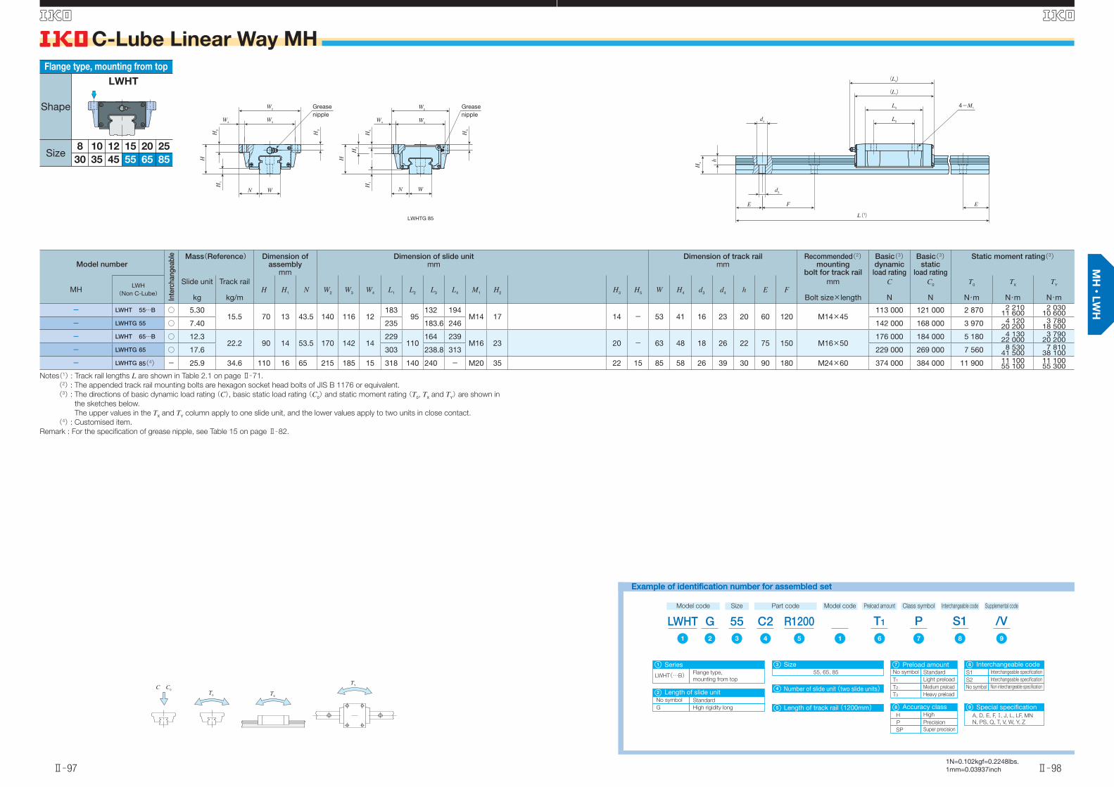
- LWHT 55…B ○ 5.3015.5 70 13 43.5 140 116 12
18395
132 194M14 17 14 - 53 41 16 23 20 60 120 M14×45
113 000 121 000 2 870 2 21011 600
2 03010 600
- LWHTG 55 ○ 7.40 235 183.6 246 142 000 168 000 3 970 4 12020 200
3 78018 500
- LWHT 65…B ○ 12.322.2 90 14 53.5 170 142 14
229110
164 239M16 23 20 - 63 48 18 26 22 75 150 M16×50
176 000 184 000 5 180 4 13022 000
3 79020 200
- LWHTG 65 ○ 17.6 303 238.8 313 229 000 269 000 7 560 8 53041 500
7 81038 100
- LWHTG 85(4) - 25.9 34.6 110 16 65 215 185 15 318 140 240 - M20 35 22 15 85 58 26 39 30 90 180 M24×60 374 000 384 000 11 900 11 10055 100
11 10055 300
Notes(1) : Track rail lengths L are shown in Table 2.1 on page Ⅱ̶71.
(2) : The appended track rail mounting bolts are hexagon socket head bolts of JIS B 1176 or equivalent.
(3) : The directions of basic dynamic load rating (C), basic static load rating (C0) and static moment rating (T0, TX and TY) are shown in
the sketches below.
The upper values in the TX and TY column apply to one slide unit, and the lower values apply to two units in close contact.
(4) : Customised item.
Remark : For the specifi cation of grease nipple, see Table 15 on page Ⅱ̶82.
Flange type, mounting from top
Shape
Size8 1210
453530
15
55
25
85
20
65
LWHT
Example of identification number for assembled setExample of identification number for assembled set
Model code
LWHTSize Part code
R1200C255G
LWHT(…B)
SeriesFlange type,
mounting from top
Preload amount Class symbol Supplemental code
T1 /VPInterchangeable code
S1Model code
1 12 76543 98
1
Number of slide unit (two slide units)4
Size55, 65, 85
3
Length of track rail (1200mm)5 Special specificationA, D, E, F, , J, L, LF, MN
N, PS, Q, T, V, W, Y, Z
9
No symbol Standard
G High rigidity long
Length of slide unit2
No symbol
T1 Light preload
Standard
T2 Medium preload
T3 Heavy preload
Preload amount7
H
P Precision
High
SP Super precision
Accuracy class 8
S1
S2 Interchangeable specification
Interchangeable specification
No symbol Non interchangeable specification
Interchangeable code8
C C0
TXT0
TY
W3
H3
H2
H1
H
WN
W4
W2
W4
H5
H1
H3
H2
H
WN
W2
W3
LWHTG 85
d3
d4
H4
h
E F E
L2
L3
(L1)
(L4)
4-M1
L(1)
Greasenipple
Greasenipple
英_Ⅱ_085_110寸法MH.indd 97-98 11.6.2 10:28:48 AM
C-Lube Linear Way MH
Ⅱ̶99
S
Ⅱ̶100
S
1N=0.102kgf=0.2248lbs.1mm=0.03937inch
Model number
Inte
rcha
ngea
ble Mass(Reference) Dimension of
assemblymm
Dimension of slide unitmm
Dimension of track railmm
Recommended(2) mounting
bolt for track rail
Basic(3) dynamic
load rating
Basic(3)static
load rating
Static moment rating(3)
MHLWH
(Non C-Lube)
Slide unit
kg
Track rail
kg/mH H1 N W2 W3 W4 L1 L2 L3 L4 M1×depth H3 W H4 d3 d4 h E F
mm
Bolt size×length
C
N
C0
N
T0
N・m
TX
N・m
TY
N・m
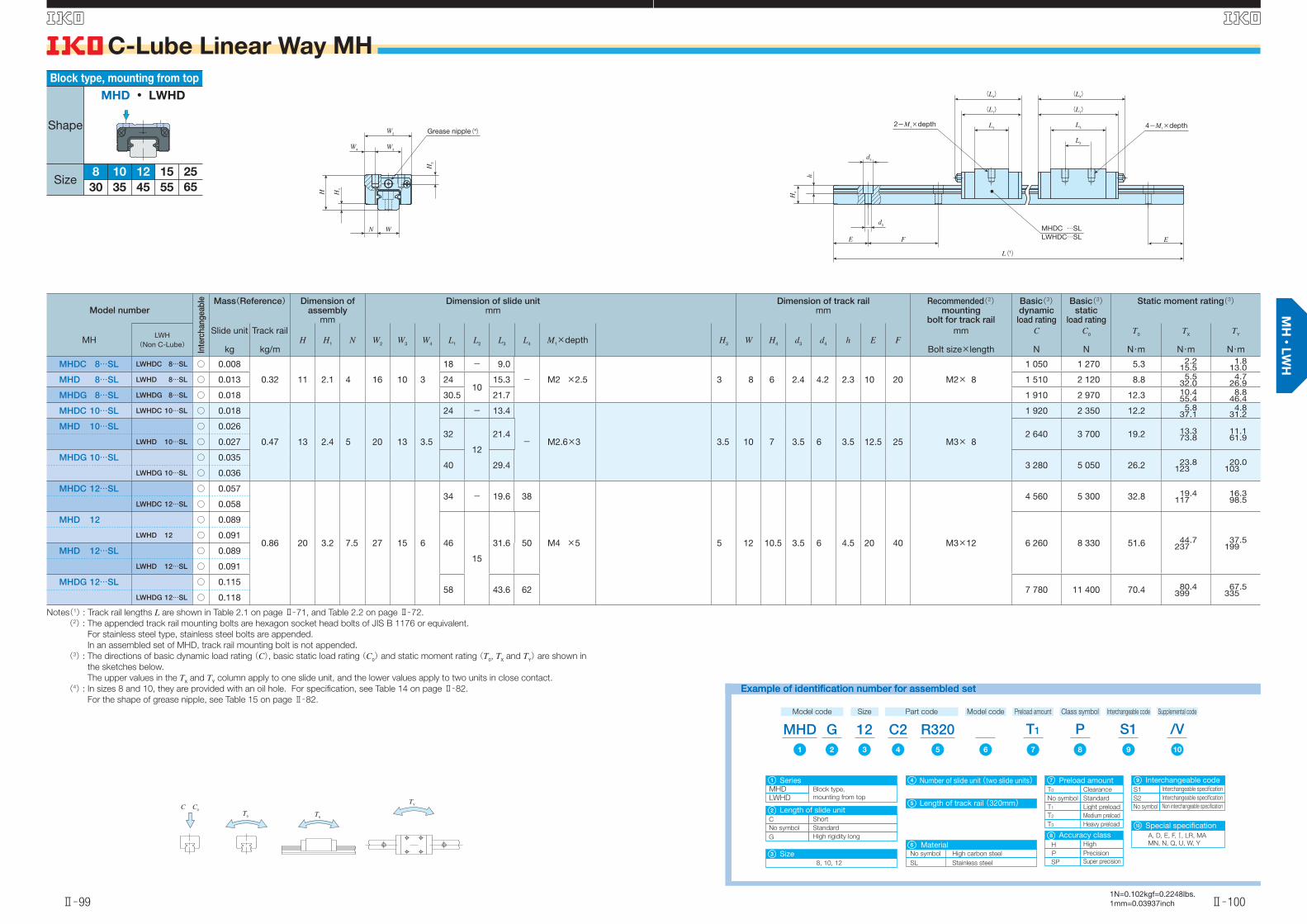
MHDC 8…SL LWHDC 8…SL ○ 0.008
0.32 11 2.1 4 16 10 3
18 - 9.0
- M2 ×2.5 3 8 6 2.4 4.2 2.3 10 20 M2× 8
1 050 1 270 5.3 2.215.5
1.813.0
MHD 8…SL LWHD 8…SL ○ 0.013 2410
15.3 1 510 2 120 8.8 5.532.0
4.726.9
MHDG 8…SL LWHDG 8…SL ○ 0.018 30.5 21.7 1 910 2 970 12.3 10.455.4
8.846.4
MHDC 10…SL LWHDC 10…SL ○ 0.018
0.47 13 2.4 5 20 13 3.5
24 - 13.4
- M2.6×3 3.5 10 7 3.5 6 3.5 12.5 25 M3× 8
1 920 2 350 12.2 5.837.1
4.831.2
MHD 10…SL ○ 0.02632
12
21.4 2 640 3 700 19.2 13.373.8
11.161.9LWHD 10…SL ○ 0.027
MHDG 10…SL ○ 0.03540 29.4 3 280 5 050 26.2 23.8
12320.0
103LWHDG 10…SL ○ 0.036
MHDC 12…SL ○ 0.057
0.86 20 3.2 7.5 27 15 6
34 - 19.6 38
M4 ×5 5 12 10.5 3.5 6 4.5 20 40 M3×12
4 560 5 300 32.8 19.4117
16.398.5LWHDC 12…SL ○ 0.058
MHD 12 ○ 0.089
46
15
31.6 50 6 260 8 330 51.6 44.7237
37.5199
LWHD 12 ○ 0.091
MHD 12…SL ○ 0.089
LWHD 12…SL ○ 0.091
MHDG 12…SL ○ 0.11558 43.6 62 7 780 11 400 70.4 80.4
39967.5
335LWHDG 12…SL ○ 0.118
Notes(1) : Track rail lengths L are shown in Table 2.1 on page Ⅱ̶71, and Table 2.2 on page Ⅱ̶72.
(2) : The appended track rail mounting bolts are hexagon socket head bolts of JIS B 1176 or equivalent.
For stainless steel type, stainless steel bolts are appended.
In an assembled set of MHD, track rail mounting bolt is not appended.
(3) : The directions of basic dynamic load rating (C), basic static load rating (C0) and static moment rating (T0, TX and TY) are shown in
the sketches below.
The upper values in the TX and TY column apply to one slide unit, and the lower values apply to two units in close contact.
(4) : In sizes 8 and 10, they are provided with an oil hole. For specifi cation, see Table 14 on page Ⅱ̶82.
For the shape of grease nipple, see Table 15 on page Ⅱ̶82.
65
Block type, mounting from top
Shape
Size8 1210
453530
2515
55
MHD ・ LWHD
Example of identification number for assembled setExample of identification number for assembled set
Model code
MHDSize Part code
R320C212
Special specificationA, D, E, F, , LR, MA
MN, N, Q, U, W, Y
Size8, 10, 12
G
MHDSeries
Block type,
mounting from topLWHD
No symbol
Length of slide unit
Standard
G High rigidity long
Preload amount Class symbol Supplemental code
T1 /VPInterchangeable code
S1Model code
1 2 876543 109
1 Number of slide unit (two slide units)4
3
2
Length of track rail (320mm)5
10C Short
No symbol
SL Stainless steel
High carbon steel
Material6
Preload amount
No symbol
T1 Light preload
Standard
T2 Medium preload
T3 Heavy preload
7
T0 Clearance
H
P Precision
High
SP Super precision
Accuracy class 8
S1
S2 Interchangeable specification
Interchangeable specification
No symbol Non interchangeable specification
Interchangeable code9
C C0
TXT0
TY
W3
H1
H
W4
W2
H3
N W
L(1)
EFE
d3
H4
h
d4
L2
L3
(L1)
(L4)
L3
(L1)
(L4)
4-M1×depth2-M1×depth
MHDC …SLLWHDC…SL
Grease nipple(4)
英_Ⅱ_085_110寸法MH.indd 99-100 11.6.2 10:28:50 AM
C-Lube Linear Way MH
Ⅱ̶101
S
Ⅱ̶102
S
1N=0.102kgf=0.2248lbs.1mm=0.03937inch
Model number
Inte
rcha
ngea
ble Mass(Reference) Dimension of
assemblymm
Dimension of slide unitmm
Dimension of track railmm
Recommended(3) mounting
bolt for track rail
Basic(4) dynamic
load rating
Basic(4)static
load rating
Static moment rating(4)
MHLWH
(Non C-Lube)
Slide unit
kg
Track rail
kg/mH H1 N W2 W3 W4 L1 L2 L3 L4 M1×depth H3 W H4 d3 d4 h M h1(2) h2 E F
mm
Bolt size×length
C
N
C0
N
T0
N・m
TX
N・m
TY
N・m
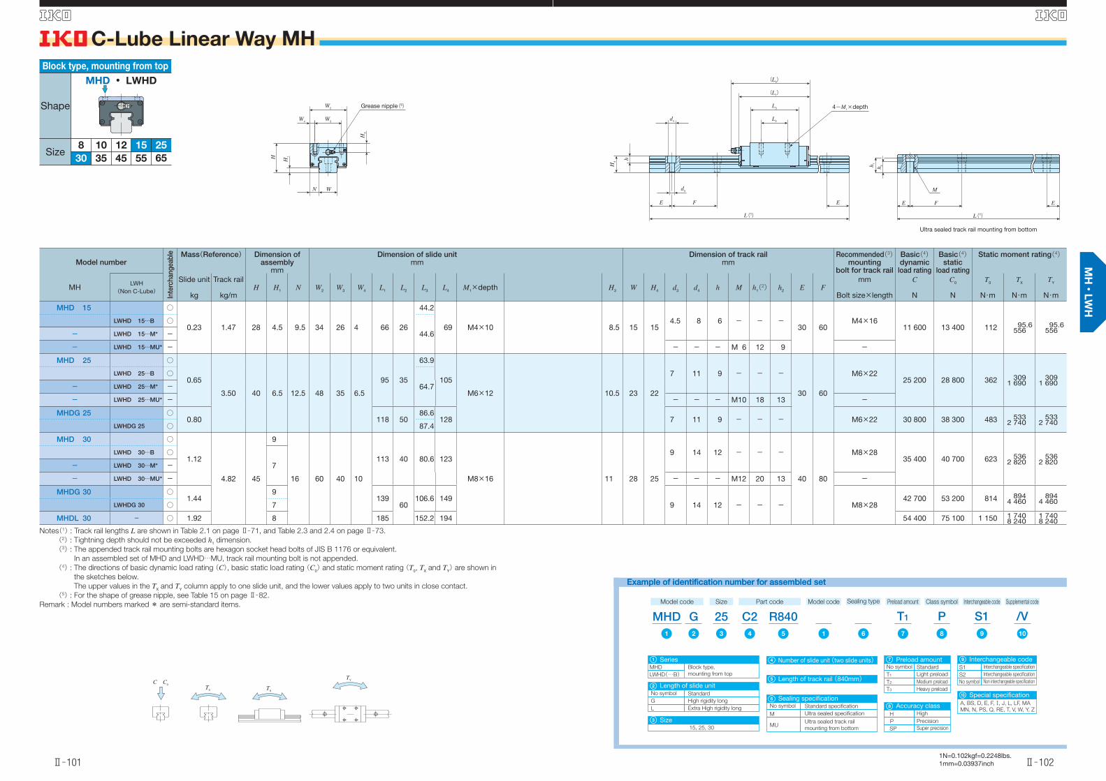
MHD 15 ○
0.23 1.47 28 4.5 9.5 34 26 4 66 26
44.2
69 M4×10 8.5 15 154.5 8 6 - - -
30 60M4×16
11 600 13 400 112 95.6556
95.6556
LWHD 15…B ○
44.6- LWHD 15…M* -
- LWHD 15…MU* - - - - M 6 12 9 -
MHD 25 ○
0.65
3.50 40 6.5 12.5 48 35 6.5
95 35
63.9
105
M6×12 10.5 23 22
7 11 9 - - -
30 60
M6×2225 200 28 800 362 309
1 690309
1 690LWHD 25…B ○
64.7- LWHD 25…M* -
- LWHD 25…MU* - - - - M10 18 13 -
MHDG 25 ○0.80 118 50
86.6128 7 11 9 - - - M6×22 30 800 38 300 483 533
2 740533
2 740LWHDG 25 ○ 87.4
MHD 30 ○
1.12
4.82 45
9
16 60 40 10
113 40 80.6 123
M8×16 11 28 25
9 14 12 - - -
40 80
M8×2835 400 40 700 623 536
2 820536
2 820LWHD 30…B ○
7- LWHD 30…M* -
- LWHD 30…MU* - - - - M12 20 13 -
MHDG 30 ○1.44
9139
60106.6 149
9 14 12 - - - M8×2842 700 53 200 814 894
4 460894
4 460LWHDG 30 ○ 7
MHDL 30 - ○ 1.92 8 185 152.2 194 54 400 75 100 1 150 1 7408 240
1 7408 240
Notes(1) : Track rail lengths L are shown in Table 2.1 on page Ⅱ̶71, and Table 2.3 and 2.4 on page Ⅱ̶73.
(2) : Tightning depth should not be exceeded h1 dimension.
(3) : The appended track rail mounting bolts are hexagon socket head bolts of JIS B 1176 or equivalent.
In an assembled set of MHD and LWHD…MU, track rail mounting bolt is not appended.
(4) : The directions of basic dynamic load rating (C), basic static load rating (C0) and static moment rating (T0, TX and TY) are shown in
the sketches below.
The upper values in the TX and TY column apply to one slide unit, and the lower values apply to two units in close contact.
(5) : For the shape of grease nipple, see Table 15 on page Ⅱ̶82.
Remark : Model numbers marked * are semi-standard items.
65
Block type, mounting from top
Shape
Size8 1210
453530
2515
55
MHD ・ LWHD
Example of identification number for assembled setExample of identification number for assembled set
Model code
MHDSize Part code
R840C225
Special specificationA, BS, D, E, F, , J, L, LF, MA
MN, N, PS, Q, RE, T, V, W, Y, Z
G
MHD
SeriesBlock type,
mounting from topLWHD(…B)
Preload amount Class symbol Supplemental code
T1 /VPInterchangeable code
S1Model code
1 12 876543 109
1 Number of slide unit (two slide units)4
Size15, 25, 30
3
Length of track rail (840mm)5
10No symbol
Length of slide unitStandard
G High rigidity long
2
L Extra High rigidity long
No symbol
T1 Light preload
Standard
T2 Medium preload
T3 Heavy preload
Preload amount7
H
P Precision
High
SP Super precision
Accuracy class 8
S1
S2 Interchangeable specification
Interchangeable specification
No symbol Non interchangeable specification
Interchangeable code9
Sealing type
No symbol
M Ultra sealed specification
Standard specification
MUUltra sealed track rail
mounting from bottom
Sealing specification6
C C0
TXT0
TY
d4
H4
d3
F
h
E E
4-M1×depth
L2
L3
(L1)
(L4)
L(1)
W3W4
WN
W2
H3
H1H
h 1
h 2
E F E
M
L(1)
Ultra sealed track rail mounting from bottom
Grease nipple(5)
英_Ⅱ_085_110寸法MH.indd 101-102 11.6.2 10:28:51 AM
C-Lube Linear Way MH
Ⅱ̶103
S
Ⅱ̶104
S
1N=0.102kgf=0.2248lbs.1mm=0.03937inch
Model number
Inte
rcha
ngea
ble Mass(Reference) Dimension of
assemblymm
Dimension of slide unitmm
Dimension of track railmm
Recommended(3) mounting
bolt for track rail
Basic(4) dynamic
load rating
Basic(4)static
load rating
Static moment rating(4)
MHLWH
(Non C-Lube)
Slide unit
kg
Track rail
kg/mH H1 N W2 W3 W4 L1 L2 L3 L4 M1×depth H3 W H4 d3 d4 h M h1(2) h2 E F
mm
Bolt size×length
C
N
C0
N
T0
N・m
TX
N・m
TY
N・m
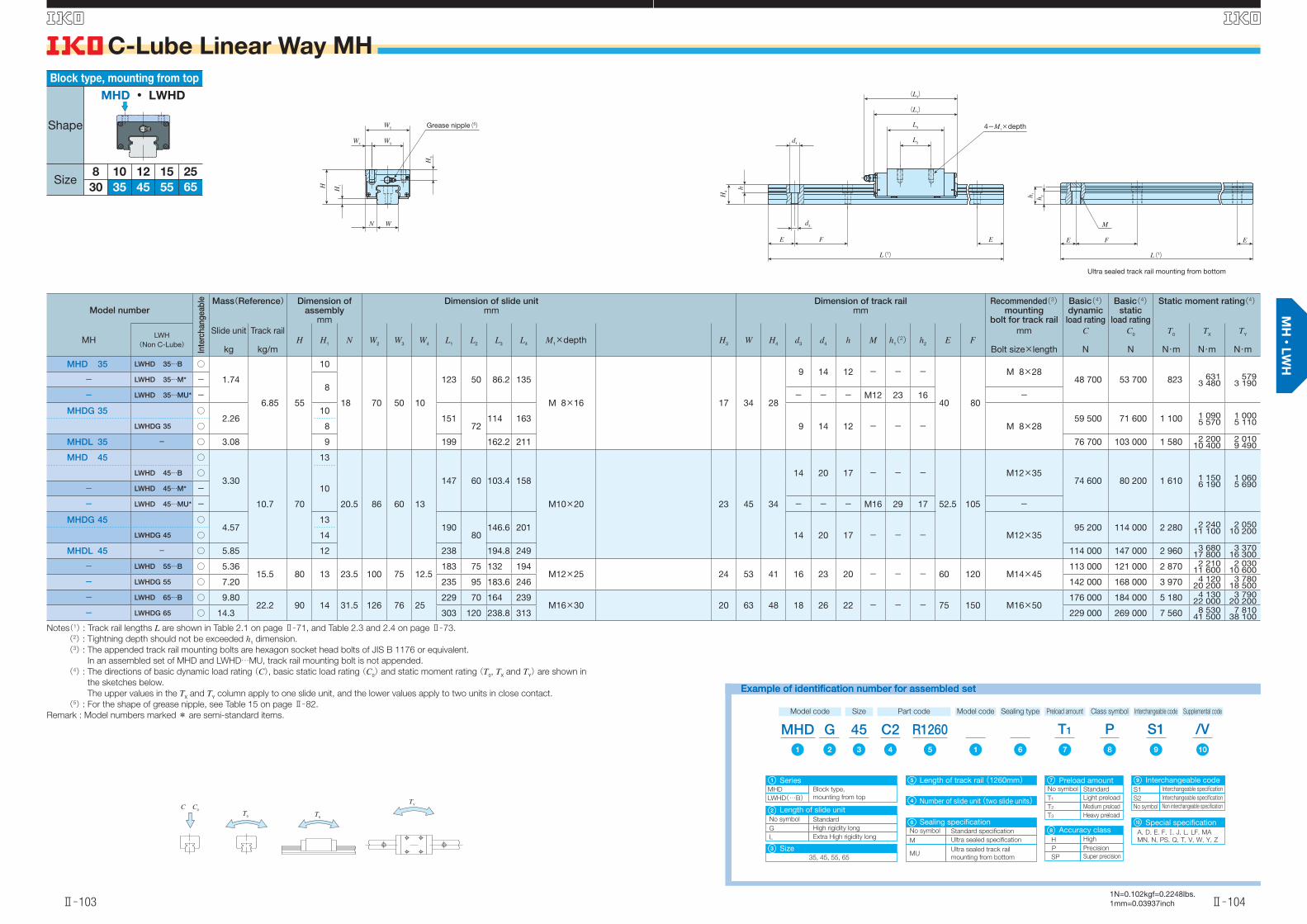
MHD 35 LWHD 35…B ○
1.74
6.85 55
10
18 70 50 10
123 50 86.2 135
M 8×16 17 34 28
9 14 12 - - -
40 80
M 8×2848 700 53 700 823 631
3 480579
3 190- LWHD 35…M* -8
- LWHD 35…MU* - - - - M12 23 16 -
MHDG 35 ○2.26
10151
72114 163
9 14 12 - - - M 8×2859 500 71 600 1 100 1 090
5 5701 0005 110LWHDG 35 ○ 8
MHDL 35 - ○ 3.08 9 199 162.2 211 76 700 103 000 1 580 2 20010 400
2 0109 490
MHD 45 ○
3.30
10.7 70
13
20.5 86 60 13
147 60 103.4 158
M10×20 23 45 34
14 20 17 - - -
52.5 105
M12×3574 600 80 200 1 610 1 150
6 1901 0605 690
LWHD 45…B ○
10- LWHD 45…M* -
- LWHD 45…MU* - - - - M16 29 17 -
MHDG 45 ○4.57
13190
80146.6 201
14 20 17 - - - M12×3595 200 114 000 2 280 2 240
11 1002 050
10 200LWHDG 45 ○ 14
MHDL 45 - ○ 5.85 12 238 194.8 249 114 000 147 000 2 960 3 68017 800
3 37016 300
- LWHD 55…B ○ 5.3615.5 80 13 23.5 100 75 12.5
183 75 132 194M12×25 24 53 41 16 23 20 - - - 60 120 M14×45
113 000 121 000 2 870 2 21011 600
2 03010 600
- LWHDG 55 ○ 7.20 235 95 183.6 246 142 000 168 000 3 970 4 12020 200
3 78018 500
- LWHD 65…B ○ 9.8022.2 90 14 31.5 126 76 25
229 70 164 239M16×30 20 63 48 18 26 22 - - - 75 150 M16×50
176 000 184 000 5 180 4 13022 000
3 79020 200
- LWHDG 65 ○ 14.3 303 120 238.8 313 229 000 269 000 7 560 8 53041 500
7 81038 100
Notes(1) : Track rail lengths L are shown in Table 2.1 on page Ⅱ̶71, and Table 2.3 and 2.4 on page Ⅱ̶73.
(2) : Tightning depth should not be exceeded h1 dimension.
(3) : The appended track rail mounting bolts are hexagon socket head bolts of JIS B 1176 or equivalent.
In an assembled set of MHD and LWHD…MU, track rail mounting bolt is not appended.
(4) : The directions of basic dynamic load rating (C), basic static load rating (C0) and static moment rating (T0, TX and TY) are shown in
the sketches below.
The upper values in the TX and TY column apply to one slide unit, and the lower values apply to two units in close contact.
(5) : For the shape of grease nipple, see Table 15 on page Ⅱ̶82.
Remark : Model numbers marked * are semi-standard items.
65
Block type, mounting from top
Shape
Size8 1210
453530
2515
55
MHD ・ LWHD
Example of identification number for assembled setExample of identification number for assembled set
Model code
MHDSize Part code
R1260C245
Special specificationA, D, E, F, , J, L, LF, MA
MN, N, PS, Q, T, V, W, Y, ZSize
35, 45, 55, 65
G
MHD
SeriesBlock type,
mounting from topLWHD(…B)
No symbol
Length of slide unitStandard
G High rigidity long
Preload amount Class symbol Supplemental code
T1 /VPInterchangeable code
S1Model code
1 12 876543 109
1
Number of slide unit (two slide units)4
3
2
Length of track rail (1260mm)5
10
L Extra High rigidity long
No symbol
T1 Light preload
Standard
T2 Medium preload
T3 Heavy preload
Preload amount7
H
P Precision
High
SP Super precision
Accuracy class 8
S1
S2 Interchangeable specification
Interchangeable specification
No symbol Non interchangeable specification
Interchangeable code9
Sealing type
No symbol
M Ultra sealed specification
Standard specification
MUUltra sealed track rail
mounting from bottom
Sealing specification6
C C0
TXT0
TY
d4
H4
d3
F
h
E E
4-M1×depth
L2
L3
(L1)
(L4)
L(1)
W3W4
WN
W2
H3
H1H
h 1
h 2
E F E
M
L(1)
Ultra sealed track rail mounting from bottom
Grease nipple(5)
英_Ⅱ_085_110寸法MH.indd 103-104 11.6.2 10:28:53 AM

C-Lube Linear Way MH
Ⅱ̶105
S
Ⅱ̶106
S
1N=0.102kgf=0.2248lbs.1mm=0.03937inch
Model number
Inte
rcha
ngea
ble Mass(Reference) Dimension of
assemblymm
Dimension of slide unitmm
Dimension of track railmm
Recommended(3) mounting
bolt for track rail
Basic(4) dynamic
load rating
Basic(4)static
load rating
Static moment rating(4)
MHLWH
(Non C-Lube)
Slide unit
kg
Track rail
kg/mH H1 N W2 W3 W4 L1 L2 L3 L4 M1×depth H3 W H4 d3 d4 h M h1(2) h2 E F
mm
Bolt size×length
C
N
C0
N
T0
N・m
TX
N・m
TY
N・m
MHS 15 ○
0.181.47 24 4.5 9.5 34 26 4
6626
44.2
69M4× 8 4.5 15 15
4.5 8 6 - - -
30 60
M4×1611 600 13 400 112 95.6
55695.6
556
LWHS 15…B ○ 44.6
MHS 15…SL ○ 44.2
LWHS 15…SL ○
44.6- LWHS 15…M* -
- LWHS 15…MU* - - - - M6 12 9 -
MHSG 15 ○ 0.25 82 60.1 85 4.5 8 6 - - - M4×16 14 400 18 300 153 172918
172918
MHS 20 ○
0.36
2.56 30 5 12 44 32 6
83 36
56
94
M5×10 5.5 20 18
6 9.5 8.5 - - -
30 60
M5×1818 100 21 100 232 195
1 090195
1 090
LWHS 20…B ○ 57.2
MHS 20…SL ○ 56
LWHS 20…SL ○
57.2- LWHS 20…M* -
- LWHS 20…MU* - - - - M8 13.5 9.5 -
MHSG 20 ○0.53 112 50
84.8122 6 9.5 8.5 - - - M5×18 24 100 31 700 349 421
2 140421
2 140LWHSG 20 ○ 86
Notes(1) : Track rail lengths L are shown in Table 2.1 on page Ⅱ̶71, Table 2.2 on page Ⅱ̶72, and Table 2.3 and 2.4 on page Ⅱ̶73.
(2) : Tightning depth should not be exceeded h1 dimension.
(3) : The appended track rail mounting bolts are hexagon socket head bolts of JIS B 1176 or equivalent.
For stainless steel type, stainless steel bolts are appended.
In an assembled set of MHS and LWHS…MU, track rail mounting bolt is not appended.
(4) : The directions of basic dynamic load rating (C), basic static load rating (C0) and static moment rating (T0, TX and TY) are shown in
the sketches below.
The upper values in the TX and TY column apply to one slide unit, and the lower values apply to two units in close contact.
(5) : For the shape of grease nipple, see Table 15 on page Ⅱ̶82.
Remark : Model numbers marked * are semi-standard items.
Compact block type, mounting from top
Shape
Size 15 2520 30
MHS ・ LWHS
Example of identification number for assembled setExample of identification number for assembled set
Model code
MHSSize Part code
R480C220
Special specificationA, BS, D, E, F, , J, L, LF, MA
MN, N, Q, RE, T, V, W, Y, Z
G
MHS
SeriesCompact block type,
mounting from topLWHS(…B)
Preload amount Class symbol Supplemental code
T1 /VPInterchangeable code
S1Model code
1 12 986543 1110
1
11
Material
7
15, 20
No symbol Standard
G High rigidity long
Number of slide unit (two slide units)
Size
Length of slide unit
4
3
2
No symbol
SL Stainless steel
High carbon steel
Length of track rail (480mm)5
Material7
No symbol
T1 Light preload
Standard
T2 Medium preload
T3 Heavy preload
H
P Precision
High
SP Super precision
Preload amount8
Accuracy class 9
S1
S2 Interchangeable specification
Interchangeable specification
No symbol Non interchangeable specification
Interchangeable code10
Sealing type
No symbol
M Ultra sealed specification
Standard specification
MUUltra sealed track rail
mounting from bottom
Sealing specification6
C C0
TXT0
TY
W2
W3
H3
H1H
W4
N W d3
d4
H4 h
EFE
4-M1×depth
L3
L2
(L1)
(L4)
L(1)
h 1
h 2
E F E
M
L(1)
Ultra sealed track rail mounting from bottom
Grease nipple(5)
英_Ⅱ_085_110寸法MH.indd 105-106 11.6.2 10:28:55 AM
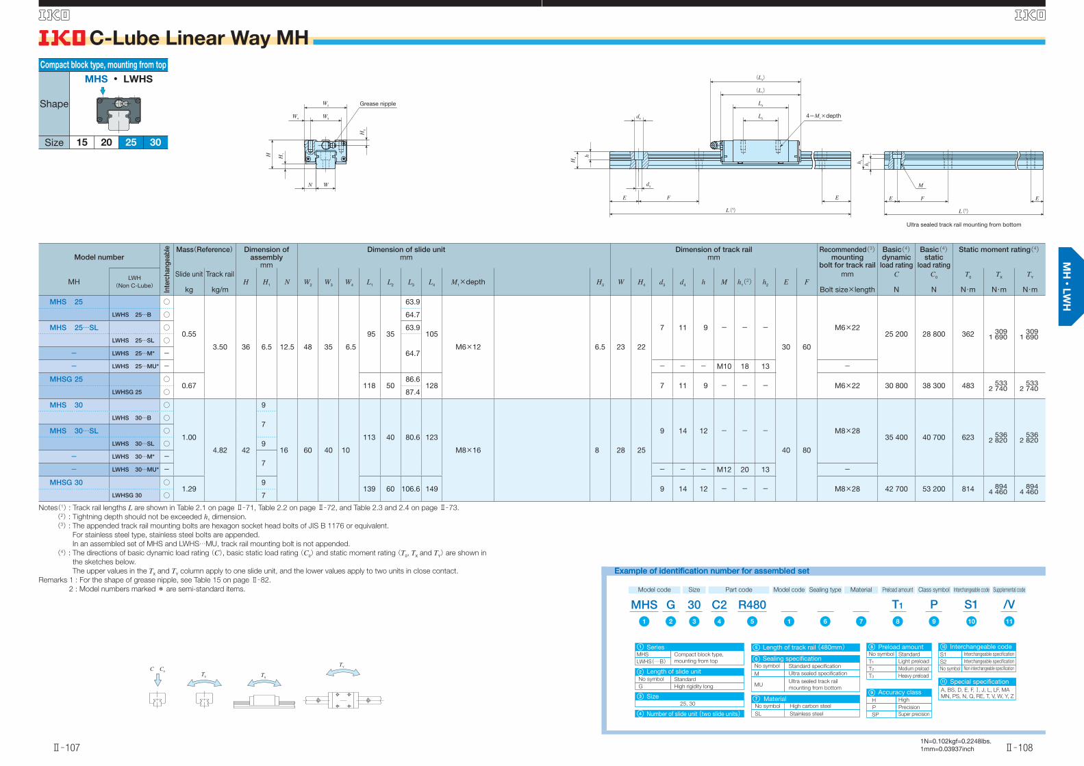
C-Lube Linear Way MH
Ⅱ̶107
S
Ⅱ̶108
S
1N=0.102kgf=0.2248lbs.1mm=0.03937inch
Model number
Inte
rcha
ngea
ble Mass(Reference) Dimension of
assemblymm
Dimension of slide unitmm
Dimension of track railmm
Recommended(3) mounting
bolt for track rail
Basic(4) dynamic
load rating
Basic(4)static
load rating
Static moment rating(4)
MHLWH
(Non C-Lube)
Slide unit
kg
Track rail
kg/mH H1 N W2 W3 W4 L1 L2 L3 L4 M1×depth H3 W H4 d3 d4 h M h1(2) h2 E F
mm
Bolt size×length
C
N
C0
N
T0
N・m
TX
N・m
TY
N・m
MHS 25 ○
0.55
3.50 36 6.5 12.5 48 35 6.5
95 35
63.9
105
M6×12 6.5 23 22
7 11 9 - - -
30 60
M6×2225 200 28 800 362 309
1 690309
1 690
LWHS 25…B ○ 64.7
MHS 25…SL ○ 63.9
LWHS 25…SL ○
64.7- LWHS 25…M* -
- LWHS 25…MU* - - - - M10 18 13 -
MHSG 25 ○0.67 118 50
86.6128 7 11 9 - - - M6×22 30 800 38 300 483 533
2 740533
2 740LWHSG 25 ○ 87.4
MHS 30 ○
1.00
4.82 42
9
16 60 40 10
113 40 80.6 123
M8×16 8 28 25
9 14 12 - - -
40 80
M8×2835 400 40 700 623 536
2 820536
2 820
LWHS 30…B ○7
MHS 30…SL ○
LWHS 30…SL ○ 9
- LWHS 30…M* -7
- LWHS 30…MU* - - - - M12 20 13 -
MHSG 30 ○1.29
9139 60 106.6 149 9 14 12 - - - M8×28 42 700 53 200 814 894
4 460894
4 460LWHSG 30 ○ 7
Notes(1) : Track rail lengths L are shown in Table 2.1 on page Ⅱ̶71, Table 2.2 on page Ⅱ̶72, and Table 2.3 and 2.4 on page Ⅱ̶73.
(2) : Tightning depth should not be exceeded h1 dimension.
(3) : The appended track rail mounting bolts are hexagon socket head bolts of JIS B 1176 or equivalent.
For stainless steel type, stainless steel bolts are appended.
In an assembled set of MHS and LWHS…MU, track rail mounting bolt is not appended.
(4) : The directions of basic dynamic load rating (C), basic static load rating (C0) and static moment rating (T0, TX and TY) are shown in
the sketches below.
The upper values in the TX and TY column apply to one slide unit, and the lower values apply to two units in close contact.
Remarks 1 : For the shape of grease nipple, see Table 15 on page Ⅱ̶82.
2 : Model numbers marked * are semi-standard items.
Compact block type, mounting from top
Shape
Size 15 2520 30
MHS ・ LWHS
Example of identification number for assembled setExample of identification number for assembled set
Model code
MHSSize Part code
R480C230
Special specificationA, BS, D, E, F, , J, L, LF, MA
MN, PS, N, Q, RE, T, V, W, Y, Z
G
MHS
SeriesCompact block type,
mounting from topLWHS(…B)
Preload amount Class symbol Supplemental code
T1 /VPInterchangeable code
S1Model code
1 12 986543 1110
1
Number of slide unit (two slide units)4
Size25, 30
3
Length of track rail (480mm)5
11
Material
7
No symbol Standard
G High rigidity long
Length of slide unit2
No symbol
SL Stainless steel
High carbon steel
Material7
No symbol
T1 Light preload
Standard
T2 Medium preload
T3 Heavy preload
H
P Precision
High
SP Super precision
Preload amount8
Accuracy class 9
S1
S2 Interchangeable specification
Interchangeable specification
No symbol Non interchangeable specification
Interchangeable code10
Sealing type
No symbol
M Ultra sealed specification
Standard specification
MUUltra sealed track rail
mounting from bottom
Sealing specification6
C C0
TXT0
TY
W2
W3
H3
H1H
W4
N W d3
d4
H4 h
EFE
4-M1×depth
L3
L2
(L1)
(L4)
L(1)
h 1
h 2
E F E
M
L(1)
Ultra sealed track rail mounting from bottom
Grease nipple
英_Ⅱ_085_110寸法MH.indd 107-108 11.6.2 10:28:56 AM

C-Lube Linear Way MH
Ⅱ̶109
S
Ⅱ̶110
S
1N=0.102kgf=0.2248lbs.1mm=0.03937inch
Model number
Inte
rcha
ngea
ble Mass(Reference) Dimension of
assemblymm
Dimension of slide unitmm
Dimension of track railmm
Recommended(2) mounting
bolt for track rail
Basic(3) dynamic
load rating
Basic(3)static
load rating
Static moment rating(3)
MHLWH
(Non C-Lube)
Slide unit
kg
Track rail
kg/mH H1 N W2 L1 L2 L3 L4 M1×depth H3 H5 H6 W H4 d3 d4 h E F
mm
Bolt size×length
C
N
C0
N
T0
N・m
TX
N・m
TY
N・m
- LWHY 15* - 0.23 1.47 28 4.5 24.3 34 66 18 44.6 69 M 4× 4 8.5 4 9 15 15 4.5 8 6 30 60 M 4×16 9 360 13 900 116 99.2577
99.2577
- LWHY 20* - 0.36 2.56 30 5 31.5 43.7 83 25 57.2 94 M 5× 5 5.5 4 10 20 18 6 9.5 8.5 30 60 M 5×18 14 500 21 900 241 2021 130
2021 130
- LWHY 25* - 0.65 3.50 40 6.5 35 47.7 95 30 64.7 105 M 6× 6 10.5 6 12 23 22 7 11 9 30 60 M 6×22 20 100 29 800 376 3201 750
3201 750
- LWHY 30* - 1.12 4.82 45 7 43.5 59.7 113 40 80.6 123 M 6× 7 11 8 14 28 25 9 14 12 40 80 M 8×28 28 100 42 200 646 5562 930
5562 930
- LWHY 35* - 1.74 6.85 55 8 51.5 69.7 123 43 86.2 135 M 8× 9 17 8 18 34 28 9 14 12 40 80 M 8×28 31 200 43 500 878 6653 600
6013 310
- LWHY 45* - 3.30 10.7 70 10 65 85.7 147 55 103.4 158 M10×11 23 10 22 45 34 14 20 17 52.5 105 M12×35 47 600 65 000 1 720 1 2006 420
1 1005 900
- LWHY 55* - 5.36 15.5 80 13 76 99.7 183 70 132 194 M12×13 24 12 25 53 41 16 23 20 60 120 M14×45 71 200 98 300 3 050 2 30012 000
2 11011 000
- LWHY 65* - 9.80 22.2 90 14 94.5 126 229 85 164 239 M16×16 20 12 30 63 48 18 26 22 75 150 M16×50 110 000 149 000 5 510 4 28022 800
3 93021 000
Notes(1) : Track rail lengths L are shown in Table 2.1 on page Ⅱ̶71.
(2) : The appended track rail mounting bolts are hexagon socket head bolts of JIS B 1176 or equivalent.
(3) : The directions of basic dynamic load rating (C), basic static load rating (C0) and static moment rating (T0, TX and TY) are shown in
the sketches below.
The upper values in the TX and TY column apply to one slide unit, and the lower values apply to two units in close contact.
(4) : For the shape of grease nipple, see Table 15 on page Ⅱ̶82.
Remark : Model numbers marked * are semi-standard items.
Side mounting type
Shape
Size15 302520
65554535
LWHY
Example of identification number for assembled setExample of identification number for assembled set
Model code
LWHYSize Part code
R480C230
Special specificationA, BS, D, E, F, , J, L, LF, MA
MN, PS, N, Q, RE, T, V, W, Y, Z
LWHY
SeriesSide mounting type
Preload amount Class symbol Supplemental code
T1 /VP1 65432 7
1
Number of slide unit (two slide units)3
Size15, 20, 25, 30, 35, 45, 55, 65
2
Length of track rail (480mm)4
7
No symbol
T1 Light preload
Standard
T2 Medium preload
T3 Heavy preload
Preload amount5
H
P Precision
High
SP Super precision
Accuracy class 6
C C0
TXT0
TY
W2
H3
H1
H5
H6
H
W
N
4-M1×depth
L(1)
d4
d3
H4
h
FE E
L2
L3
(L1)
(L4)
Grease nipple(4)
英_Ⅱ_085_110寸法MH.indd 109-110 11.6.2 10:28:58 AM