Bremen´s 100-MW static frequency link - ABB Group · Bremen GmbH - is supplied by pipelines with a...
17
\\CHIND-TU01-C102\H09134$\Work\ABB Review Article Bremen.doc Page 1 of 17 ABB Review Article Bremen´s 100-MW static frequency link Issue-No: 9,10/96 (pp.4-17), M420 Author(s): Osvin Gaupp, ABB Industrie AG, Plinio Zanini, ABB Power Generation Ltd, Peter Daehler, ABB Industrie AG, Eugen Baerlocher, ABB Industrie AG, Ruediger Boeck, Stadtwerke Bremen AG, Johannes Werninger, ABB Industrie AG Static frequency converters are today the equipment of choice for the links that exchange energy between railway power supplies and national electricity grids. At 100 MW, the 'Bremen' static frequency link in Germany is currently the world´s highest rated installation of its kind to employ GTO thyristor technology. Further development of the GTO thyristors, which are connected in series, plus a new type of gate unit, made the high rating and good economy of the link - between a 16 2/3-Hz and a 50 Hz system - possible. The advantages of the new installation over earlier links include high availability and a considerably better efficiency over the full power range.
Transcript of Bremen´s 100-MW static frequency link - ABB Group · Bremen GmbH - is supplied by pipelines with a...

\\CHIND-TU01-C102\H09134$\Work\ABB Review Article Bremen.doc Page 1 of 17
ABB Review Article
Bremen´s 100-MW static frequency linkIssue-No: 9,10/96 (pp.4-17), M420
Author(s): Osvin Gaupp, ABB Industrie AG, Plinio Zanini, ABB Power Generation Ltd, PeterDaehler, ABB Industrie AG, Eugen Baerlocher, ABB Industrie AG, Ruediger Boeck, StadtwerkeBremen AG, Johannes Werninger, ABB Industrie AG
Static frequency converters are today the equipment of choice for the links that exchangeenergy between railway power supplies and national electricity grids. At 100 MW, the'Bremen' static frequency link in Germany is currently the world´s highest rated installationof its kind to employ GTO thyristor technology. Further development of the GTO thyristors,which are connected in series, plus a new type of gate unit, made the high rating and goodeconomy of the link - between a 16 2/3-Hz and a 50 Hz system - possible. The advantages ofthe new installation over earlier links include high availability and a considerably betterefficiency over the full power range.

\\CHIND-TU01-C102\H09134$\Work\ABB Review Article Bremen.doc Page 2 of 17
For historical reasons, traction power supplies in many countries have frequencies which aredifferent to the frequency of the national grid or, alternatively, are operated with direct current [1, 2,3]. Although the railways have their own power plants, the strong fluctuation in power demandoften makes it necessary for the supply systems to also be connected to the national grid. InGermany, for example, ties exist between the traction power supply and the national grid at about40 locations. Besides meeting about a quarter of the railways' total power demand, these ties alsoallow the traction power supplies to be stabilized. Also, since most of them can be used toexchange energy in both directions (ie, from the 50-Hz to the 16 2/3-Hz system, and vice versa),traction power generation can be scheduled in a more economical way.
Operation of the frequency link and environmental protectionBlast-furnace gas - a byproduct of pig iron production at the German steel company StahlwerkeBremen GmbH - is supplied by pipelines with a diameter of up to 1.8 m to the Mittelsbüren powerplant, which is located near the steelworks. The electric utility Stadtwerke Bremen AG, which ownsthe power plant, burns the gas in turbines to generate electrical power for German Railway. Thiscollaboration, which began in 1964, is of considerable ecological importance as it saves coal whichwould otherwise have to be burnt in other power plants to meet demand. CO2 emissions aresubstantially reduced as a result.
The drop in traction power demand at weekends made it necessary in the past to burn off a certainamount of the blast-furnace gas. Since the static 100-MW frequency link has been operating inMittelsbüren, the blast-furnace gas can be utilized more efficiently as Stadtwerke Bremen canconvert the traction power into three-phase AC power, and vice versa. In the future, it will bepossible to use almost all of the gas to generate electrical power. Also, any power which GermanRailway does not want can be converted and fed into the power system of Stadtwerke Bremen.
Hitherto, the environmental benefit accruing from the cooperation between the steelworks, railwayauthorities and electric utility has been equivalent to about 750,000 t of CO2 per year, this beingthe amount that other power plants would otherwise have emitted. With the new converter, anadditional reduction of 150,000 t of CO2 will be achieved each year.
The static frequency link for exchanging energy between the 16 2/3-Hz system and the 50-Hzsystem also helps to secure a more reliable supply of power in the two networks, since a powershortfall in one of the systems can be compensated for by the other.
With the help of the new system tie, the traction power units of the Mittelsbüren plant can beincluded in the three-phase AC power generation (or power from the 50-Hz system supplied to the16 2/3-Hz system in an economical way) when less or even no blast-furnace gas is available, orwhen the full power plant rating is not at disposal for other reasons. This not only ensures goodmatching of the power plant capacity to the actual supply, fuel and cost situation, but also makessure that the contractual obligations to German Railway are met independently of the supply ofblast-furnace gas.
From rotary to static convertersTraditionally, converter stations linking traction power supplies with national grids have had rotaryconverters installed in them. In recent decades, the increasing reliability of power semiconductordevices, and particularly the successful introduction of gate turn-off (GTO) thyristors, hasmade static converter installations the preferred option. The benefits they offer are as follows:
• An improvement in efficiency of about 5 percent over the entire power range [2]

\\CHIND-TU01-C102\H09134$\Work\ABB Review Article Bremen.doc Page 3 of 17
• Lower first-time costs due to the elimination of the costly foundations for rotatinginstallations
• Longer intervals between maintenance, plus shorter downtimes, resulting in higheravailability
• Modular design of the components, making the equipment easier to service
Static traction power links built in the past have featured converter units with a rating no higherthan about 15 MVA. ABB recently took a first step towards higher ratings with the 2 x 25-MVAinstallation for Swiss Federal Railway's converter station at Giubiasco, in southern Switzerland.This installation was placed in commercial operation in 1994 [1, 3].
A single converter with high rating for BremenIn 1991, Stadtwerke Bremen AG awarded ABB Power Generation and ABB Industrie AG acontract to study the feasibility of building a high-power converter for exchanging electrical energybetween a 16 2/3-Hz and 50-Hz system; the converter was to be built with GTO thyristors in seriesconnection and have a transmission rating of up to 100 MW in both directions. The feasibility studyshowed that further development of the GTO thyristors, their series connection and use of aninnovative hard driven gate unit [4], would allow an economical static frequency link to be built thatsatisfies these conditions.
The main technical data of the Bremen frequency link are given in Table 1. The installationconsists of a single converter ratedat 100 MW/MVA. This tremendousleap in power rating was madepossible by several innovations inGTO thyristor technology thatguarantee highest reliability.
A single converter unit which iscapable of the full power ratingoffers higher efficiency thanconverters made up of multipleunits. In addition, the smallernumber of componentsautomatically improves thereliability, while investment andrunning costs are also lower. It isworth noting, too, that in Bremen allof the necessary redundancy isintegrated in the converter itself.
Frequency link circuit and configurationThe main power circuit of the Bremen frequency link consists primarily of the thyristor converter onthe three-phase AC side, the DC voltage link, the GTO converter on the 16 2/3-Hz side, and theconverter transformers. Also shown in Image 1 is the filter and compensation equipment for thethree-phase AC network and the DC link, plus the main overvoltage protection gear and theequipment for protecting the station in the event of 'shoot-through'. The voltage and frequency of

\\CHIND-TU01-C102\H09134$\Work\ABB Review Article Bremen.doc Page 4 of 17
the power system operated by Stadtwerke Bremen AG remain practically constant. In the tractionpower supply, on the other hand, both the voltage (97-123 kV) and the frequency (16.3-17.0 Hz)fluctuate considerably in normal operation. The nominal voltage and nominal current of the DC linkare 10 kV and 10.5 kA, respectively.
1
2
The new installation is located directly behind the 110-kV substation of Stadtwerke Bremen AGand immediately next to German Railway's 110-kV substation. The converter and the control and
\\CHIND-TU01-C102\H09134$\Work\ABB Review Article Bremen.doc Page 5 of 17
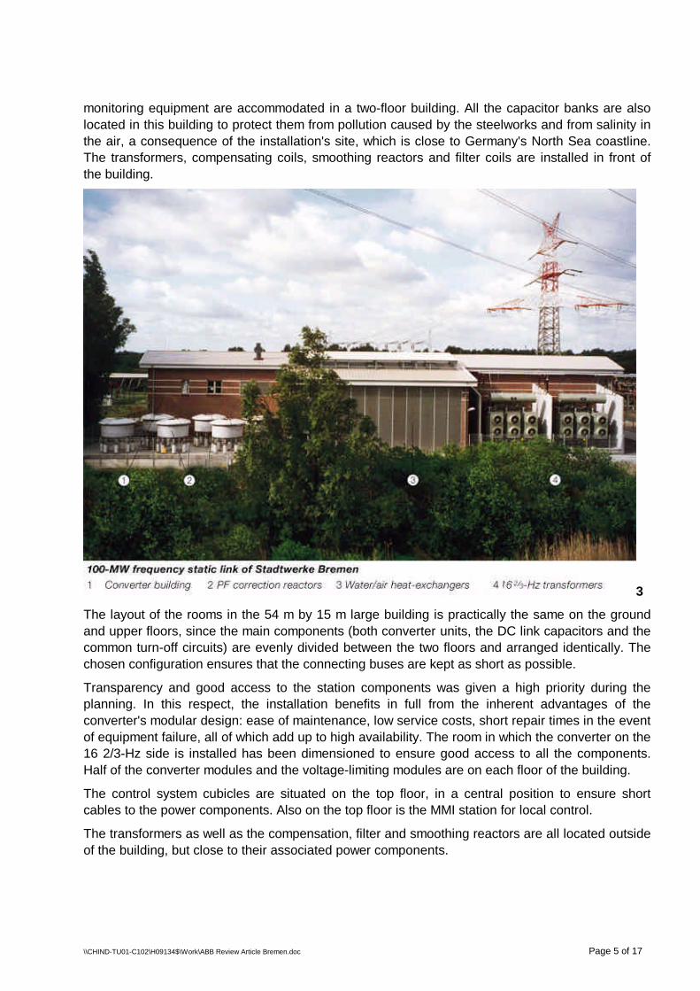
monitoring equipment are accommodated in a two-floor building. All the capacitor banks are alsolocated in this building to protect them from pollution caused by the steelworks and from salinity inthe air, a consequence of the installation's site, which is close to Germany's North Sea coastline.The transformers, compensating coils, smoothing reactors and filter coils are installed in front ofthe building.
3
The layout of the rooms in the 54 m by 15 m large building is practically the same on the groundand upper floors, since the main components (both converter units, the DC link capacitors and thecommon turn-off circuits) are evenly divided between the two floors and arranged identically. Thechosen configuration ensures that the connecting buses are kept as short as possible.
Transparency and good access to the station components was given a high priority during theplanning. In this respect, the installation benefits in full from the inherent advantages of theconverter's modular design: ease of maintenance, low service costs, short repair times in the eventof equipment failure, all of which add up to high availability. The room in which the converter on the16 2/3-Hz side is installed has been dimensioned to ensure good access to all the components.Half of the converter modules and the voltage-limiting modules are on each floor of the building.
The control system cubicles are situated on the top floor, in a central position to ensure shortcables to the power components. Also on the top floor is the MMI station for local control.
The transformers as well as the compensation, filter and smoothing reactors are all located outsideof the building, but close to their associated power components.

\\CHIND-TU01-C102\H09134$\Work\ABB Review Article Bremen.doc Page 6 of 17
Principle of operation and equipment layout on the 16 2/3-HzsideThe direct voltage of the DC link is kept constant by the converter on the three-phase AC side. TheGTO thyristor converter generates an internal voltage with freely adjustable amplitude and phaseand a frequency which is determined by the interconnected operation. The reference quantities forthe manipulated variables of the converter are the voltage and phase relation at the tie to thetraction power supply.
4a,b
The vector diagram in (Image 4b) illustrates the principle of operation of the converter with GTOthyristors. A key role is played by the short-circuit reactance XT of the single-phase convertertransformer (Image 4a). The internal converter voltage UBi can be freely chosen within certainlimits (grey area). This defines the voltage drop DUT and with it the amplitude and phase of thecurrent IB.
The availability of reactive power is limited by the maximum internal voltage that can be set. This isdefined by the direct voltage of the DC link and the converter control procedure described in thefollowing. In connection with this, it should be noted that the restrictions on the switching time donot allow the full control voltage ust to be utilized (the maximum control voltage factor is 0.96).

\\CHIND-TU01-C102\H09134$\Work\ABB Review Article Bremen.doc Page 7 of 17
The apparent power SB is limited by the maximum current IB that can be conducted by the GTOconverter and the converter transformer (small circle in Image 4b). Whereas in the case of the
transformer this limithas only thermalorigins, in the case ofthe converterconsideration alsohas to be given to theturn-off capability. Inaddition, the activepower limits (the
perpendicularborders of the greyarea) depend on thedesign of the infeedcircuit (thyristorconverter, etc) on thethree-phase AC side.
The PQ diagram representing the 16 2/3-Hz side corresponds to the defined power data (Table 2).The circle for UB = 121kVincludes the three specifiedoperating points A, B and C,and corresponds to themaximum current allowed forthe GTO thyristor converter.This also determines themaximum power at a lowerrailway network voltage. In theoverexcited range, the powerlimit is defined at point B by themaximum possible convertervoltage.
Since an additional antiparallelthyristor converter with thesame power rating is installed,the symmetrical operatingpoints A', B', C' are valid for theenergy flow from the 16 2/3-Hzside to the 50-Hz side.
5

\\CHIND-TU01-C102\H09134$\Work\ABB Review Article Bremen.doc Page 8 of 17
Control method and output voltageThe proven PWM (pulse width modulation)method was chosen for the control, thismethod being used widely today for drivesystems. The switching commands for theindividual phase modules (U-modules) aregenerated on the basis of a comparison of theinstantaneous values of the sinusoidal controlvoltage ust with the triangular carrier voltages(auxiliary control voltages uhm and uhp). Thecarrier frequency corresponds to three timesthe traction power system frequency. EachGTO thyristor therefore performs threeswitching cycles for every period on the 162/3-Hz side.
All twelve GTO thyristor bridges are controlledusing the PWM method; the carrier signals of two adjacent stages are displaced electrically by 15 °(180 °/12, referred to the carrier period). Because of this there are 12 mutually displaced stepvoltages. The summation of these step voltages, which takes place due to the series connection ofthe high-voltage windings in the 16 2/3-Hz transformer, results in an approximately sinusoidaloutput voltage with a very low harmonic content. No additional filters are necessary.
7
The output voltage is controlled by means of adjustment of the amplitude of the control voltage ustand its phase relation d, referred to the traction system voltage UB at the point where the frequencylink is connected.
6

\\CHIND-TU01-C102\H09134$\Work\ABB Review Article Bremen.doc Page 9 of 17
Converter on the 16 2/3-Hz sideThe high power rating of Bremen's frequency link was made possible in the first place by keytechnological advances that are incorporated in the GTO thyristors used in the converter on the 162/3-Hz side. This converter consists of (Image 1):
• Twelve H-bridges, each with two phase modules, connected in parallel with the DC voltagelink
• Four voltage limiters in the DC voltage link
• The DC voltage link, coupled direct and consisting of a low-inductance busbar andcapacitors
• The valve base electronics
Low-inductance phase modules
Each of the phase modules has six GTO thyristors connected in series. The phase module with theDC link bus and the directly connected capacitors is designed with a very low inductance to ensurethat only minimal energy is stored in the leakage inductance, thereby minimizing the voltage stressduring switching.
Very low-inductance HV capacitors (200 nH per 10-kV unit) are used for the DC voltage link. Thecapacitor elements are built using self-healing, drytechnology. In the event of an internal defect in theinsulation, evaporation of the metal layer isrestricted to the immediate locality, and no short-circuit occurs.
The power semiconductors, resistors in the snubbercircuits and current-limiting reactors are cooled withdeionized water. The reliability of the converter isalso increased by this (no fans for forced-aircooling).
Series connection and redundancy
The series connection of the GTO thyristors calls forprecise timing of the switching, with all of the series-connected GTO thyristors capable of being switchedwithin 200 ns. To this end, ABB developed the so-called hard driven gate unit, which features a muchhigher rate of rise and amplitude than conventionalgate drives [4]. To achieve this, the inductance ofthe gate unit had to be reduced by a factor of about100, requiring a completely new design in which theGTO thyristor and gate unit are united in a single,compact module.
The nominal direct voltage of the DC link is 10 kV.Four GTO thyristors connected in series in eachbranch of the bridge are sufficient for this rating.With six GTO thyristors connected in series, one
semiconductor device could fail without causing the installation to perform at less than its full level.
8

\\CHIND-TU01-C102\H09134$\Work\ABB Review Article Bremen.doc Page 10 of 17
If a second thyristor in the same branch should fail, controlled shut-down of the installation isinitiated. The incorporation of redundant semiconductor devices reduces the voltage stress level ofall of the components and significantly improves their mean lifetime.
Calculations based on field data show that a converter with GTO thyristors connected in series andwith integrated redundancy will, on average, suffer a total breakdown just once in seven years.This figure presupposes annual maintenance, during which any defective redundant componentsidentified during operation are replaced. The availability can be significantly improved by replacingthese components at shorter intervals.
DC link bus connections
The low-inductance design principle also applies to those parts of the DC link that are closely tiedelectrically to the converter. The voltage link conductors therefore consist of two flat bars runningparallel to each other with just a layer of MICADUR® insulation separating them. Since internalshort-circuits could cause considerable mechanical stress, the structure has been designed towithstand every conceivable fault event. After being calculated and simulated, the stress withstandcapability was also tested in ABB's high power laboratory.
Voltage limiter
Fast-acting control circuits ensure thatthe DC voltage is kept constant by theinfeed thyristor converter. Nevertheless,disturbances in either of the two powersystems can cause transient overvoltages. To protect the converter, avoltage limiter has been integrated whichconnects a load resistor into the DC linkthe moment the permitted voltage limit isreached. The voltage limiter consists offour parallel GTO thyristor switches withload resistors. These are, in effect, fourslightly modified branches of the phasemodule of the GTO thyristor converter towhich a resistor and freewheeling diodeshave been added.
Protection
The three-stage protection concept comprises prevention, protection firing, and damagecontainment in emergency situations. The overriding philosophy is that everything has to be doneto prevent fault situations from occurring in the first place. This end is served by redundant GTOthyristors as well as controlled shut-down in the event of failure of a second thyristor in the samebranch. In addition, the two branches of a GTO thyristor phase are interlocked to prevent themfrom becoming conductive simultaneously.
If the preventive measures fail, shoot-through is detected within just a few microseconds by ameasuring device (also provided in redundant mode). To relieve the defective GTO thyristor phase,all the other phases of the converter are turned on (protection firing). The design of the converterensures such that this causes no damage. Besides, the integrated preventive measures ensurethat protection firing occurs on only very rare occasions.
9

\\CHIND-TU01-C102\H09134$\Work\ABB Review Article Bremen.doc Page 11 of 17
The GTO thyristor converter has also been designed to withstand faults in the event of failure ofthe protection system. Although all of the semiconductor devices (GTO thyristors and diodes) in adefective phase can be destroyed by the full fault current flowing through a central fault location,there will be neither mechanical nor thermal secondary damage as a result of this. No plasma isformed and no components will explode.
Verification
Since the GTO thyristor converter in Bremen is the first of its kind and features largely newtechnologies, special importance was attached to the verification of the components andsubassemblies used in it. This was carried out by simulation with highly sophisticated models andby laboratory testing of the different parts of the installation.
The program used for the simulation was a new one with improved models of the powersemiconductors. The parameters were obtained from special measurements carried out on thehardware. In this way it was possible, for example, to verify the shoot-through and protection firingwithin the context of the overall installation and the power systems. In addition, the influence of thecomponent tolerances could be clarified and worst-case tests could be carried out.
Besides the type-tests, which were performed in accordance with the standards, several othertests were carried out. These included:
• Tests to determine what happens in the high-frequency range during transient faults in thetraction power system.
• Impulse current tests to verify that no mechanical damage is caused to the components inthe event of all the protection stages failing.
• Further impulse current tests to verify that the characteristic data of the semiconductordevices do not change even after as many as 100 instances of protection firing.
• An endurance test lasting longer than 100 h under the following conditions: 150 percentrated current, 120 percent rated voltage, 150 percent nominal frequency and zeroredundancy [4].
Transformers on the 16 2/3-Hz sideThe summation transformer on the traction power side consists of six two-phase units with yoke.
Since the two phases are decoupledmagnetically by the yoke, they act asindividual transformers. The secondarywindings of the two phases receive powerfrom adjacently modulated GTO thyristorbridges. Although their fundamentalcomponents are in phase, the harmonicsare phase-shifted due to the displacedpulse pattern, resulting in a magnetic flux inthe yoke equal to approximately 10 percentof the main flux in the wound yoke duringsteady-state operation. Despite this, thereturn limb's cross-section has the samedimensions as the main limb to allowtemporary (eg, during power system faults),
virtually independent switching of the two GTO thyristor bridges without any risk of the transformerbecoming saturated.
10

\\CHIND-TU01-C102\H09134$\Work\ABB Review Article Bremen.doc Page 12 of 17
A conventional three-phase AC transformer core made of grain-oriented magnetic sheet steel andwith windings on just the outer yokes was therefore used for the two-phase unit. Each yoke carriesone primary (16 2/3-Hz side) and one secondary winding in a concentric arrangement. All theprimary windings are insulated for the full test voltage. Two two-phase units share a common tank.
Special attention was paid to the open-circuit leakage impedance of the individual phase systems.The spread of these impedances had to be limited as much as possible as it determines how thetraction power system voltage is divided between the transformers (and therefore among the GTOthyristor bridges) when the thyristor valves are non-conducting. A very uneven distribution couldlead to the amplitude of the alternating voltage in the bridges with the largest share of the voltagebeing higher than the DC link voltage. This would cause overloading of the DC link via the diodesin the H-bridges.
Another recognized problem involves the DC voltage components that appear in the output voltageof the thyristor bridges when the timing of the switching is not optimal. Even a relatively smallproportion of these components can lead to signs of transformer saturation or load the bridges withmagnetizing current, and even make operation impossible. The problem grows with the size of theinstallation and is further intensified by the series connection of the GTO thyristors. In the Bremenlink, a constant error of just 1 µs per phase would lead to a DC voltage component of 33 mV,causing a magnetic bias of approximately 1.4 T. By comparison, the operational induction with amaximum output voltage is 1.55 T. To make sure that any DC voltage component that might occuris limited, an innovative system was developed which promptly detects such components andlowers their value to an acceptable level.
Design of the DC linkThe main purpose of the DC voltage link is to de-couple the three-phase AC power system fromthe traction power supply. It has to ensure that the GTO thyristor converter is supplied with aconstant direct voltage and at the same time prevent harmonics on the 16 2/3-Hz side fromreaching the 50-Hz circuit. Also important, for protection reasons, is the minimization of thedistributed capacitance CD, which is hard-wired to the converter.
One result of the traction power supply being a single-phase system is that power oscillation withdouble the traction power frequency occurs. A tuned 33-Hz filter therefore has to be incorporated inthe DC link. The link rating is defined by the ripple in the direct voltage that can be tolerated underthe assumption of maximum frequency deviation in the traction power supply and worst-case filterdetuning.
The traction power converter must also be capable of trouble-free operation in cases of relativelystrong distortion of the traction power supply voltage. The 3rd and 5th harmonics, in particular, canreach high values. To achieve the necessary insensitivity to these harmonics, a damped highpassfilter is integrated in the DC link in addition to the 33-Hz filter.
50-Hz-side converter and compensation equipmentPower is fed into the system from the Stadtwerke Bremen grid via a line-commutated 12-pulsethyristor converter, this being more economical than a self-commutated converter.
The high level of grid cabling results in excessive reactive power, which has to be compensated forduring low-load periods by reactors. The reactance coils can also be connected into circuitwhenever the frequency link is not in operation. Filters and reactors are switched mechanically toobtain the required reactive-power range in the most economical way. The filter design ensuresadherence to the prescribed limits for voltage distortion (< 1.5 percent).

\\CHIND-TU01-C102\H09134$\Work\ABB Review Article Bremen.doc Page 13 of 17
The thyristor converter configuration for the nominal data of the DC link has four thyristorsconnected in series and three branches connected in parallel. Like the GTO thyristor converter,this installation can continue to operate unrestricted if one thyristor per branch should fail. Failureof a second thyristor in the same branch results in controlled shut-down of the installation. Thisensures that the healthy part of the branch is not endangered. The current distribution in theparallel branches is monitored. If one branch does not participate in the current conduction (e.g.,due to a fault in the gate unit), the DC link current is limited accordingly.
Any surplus energy that is present in the traction power supply is fed into Stadtwerke Bremen'selectricity grid via a second, antiparallel thyristor converter operating as an inverter. Theconverter's control system allows fast power reversal.
A high priority was given to the protection of the converter when it is being operated in invertermode. This protection is provided by a common turn-off circuit comprising static devices for forcedcommutation (Image 1).
Unlike conventional HVDC installations with current-controlled converters on both sides, the circuitin the Bremen station does not allow control of the fault current in the DC link. Even when theinverter control is carefully designed, commutation failures (eg, during transients in the three-phaseAC network) can never be entirely excluded.
Inverter commutation failures are detected by two independent measuring circuits, both sides ofthe converter being blocked as soon as a failure is identified. A negative reverse current is appliedto the defective inverter valve, which is turned off as a result. Approximately one power systemperiod is required for the entire turn-off process. After a short time of about 1 s, which is needed torestore the turn-off function to its original status, transmission starts up again automatically. Thefunctional availability of the common turn-off circuit is monitored continuously.
Valve base electronicsEvery converter is assigned an electronics package which generates the pulse telegrams from thefiring commands given by the controller and transmits them over fiber optic wires to the individualsemiconductor locations, where they are converted by indirect light pulse firing (via the thyristorelectronics) into electrical firing pulses. The valve base electronics also monitors, with the help ofreturn signals from the thyristor electronics, the redundancy of the series-connected semiconductordevices, producing an alarm or trip signal whenever the level of redundancy is reduced.Semiconductor devices which have failed are identified and can be replaced the next time routinemaintenance is carried out.
The overvoltage limiter in the DC link of the GTO thyristor converter is also controlled by the valvebase electronics. The same electronics is further responsible for high-speed detection (inredundant mode) of shoot-throughs and for tripping the protection firing of the GTO thyristorconverter.In the case of the thyristor converter, this electronics package also controls the common turn-offcircuit. Return signals enable the controller to quickly identify commutation failures when theconverter is operating in inverter mode.

\\CHIND-TU01-C102\H09134$\Work\ABB Review Article Bremen.doc Page 14 of 17
Control and monitoring systemThe installation is controlled and monitored by a S.P.I.D.E.R. MicroSCADA system run on anALPHA workstation. This system, which also records status changes and disturbances, can be
operated from a local controlroom, from the nearbyMittelbüren power plant, orfrom Stadtwerke Bremen'sload dispatching centerapproximately 20 km away.The operating authority canbe selected as required. Theinstallation itself isunattended.
Control and protection of thefrequency link are based onABB's programmable high-speed control system, PSR2[5]. PSR2 was developedespecially for complex powerelectronics systems, making itthe ideal solution for theBremen link. It combines ahigh processing speed with anextremely user-friendlygraphic programminglanguage (FUPLA 2). Thecombination of these twofeatures ensures a high levelof operational flexibility. Boththe graphic programminginterface of the system andS.P.I.D.E.R. MicroSCADA canbe accessed over a telephoneline for diagnostics purposes.
The control system isresponsible for sequentialstart-up and shut-down of theinstallation as well as forensuring stable operation.
11

\\CHIND-TU01-C102\H09134$\Work\ABB Review Article Bremen.doc Page 15 of 17
The main control task onthe 50-Hz side is to keepthe DC link voltageconstant. To optimizethe dynamic responseand for protectionreasons, a configurationwith cascade controller,superimposed voltageregulator andsubordinate DC currentcontroller was chosen.Control on this side alsoincludes the switching ofthe thyristor converterswhen the power isreversed. As with HVDCconverter stations, thetriggering equipment issynchronized by means
of a phase-locked loop (PLL).
The current (IB) and voltage (UB) measured on the 16 2/3-Hz traction power side are used tocalculate the active and reactive power. Active power is controlled according to a load-frequencycharacteristic, and reactive power on the basis of a voltage/reactive power curve. The pulse-widthmodulator is synchronized by means of a phase-locked loop, which is also used to measure thetraction power system frequency.
The protection is designed with two channels for full redundancy. If a system fails as the result of ahardware fault, its tripping channels are automatically blocked. The installation protection as awhole is not affected by this. The operating staff are informed of the fault and of the defectiveequipment involved via the man-machine interface. Replacement of the hardware,parameterization and testing of the protection functions can be carried out for every protectionsystem with the installation still in operation.
Design and verificationThe Bremen frequency link was designed and verified with the help of three tools:
• Analytical software
• Simulation software
• ABB simulator (with 50-W scale, for the physicalsimulation)
The first two tools offer high accuracy and reproducibilityover a wide frequency range, while the special strength ofthe simulator is its real-time capability. This allows theentire system to be safely tested using real-world controland monitoring equipment.
For example, it was possible to develop the main functionsof the control system on the physical simulator using the
12
13

\\CHIND-TU01-C102\H09134$\Work\ABB Review Article Bremen.doc Page 16 of 17
DC link values of 200 V and 250 mA. Before being delivered, the control system cubicles were tiedinto the simulator configuration and tested in collaboration with Stadtwerke Bremen under veryrealistic normal and fault conditions.
CommissioningDuring commissioning, high priority was given to step-by-step verification of the correct electrical,thermal and mechanical design of all parts of the installation. After all the standard pre-commissioning tests had been carried out (voltage tests, tests on the control system andprotection, etc), the subsystems were tested in the following order:
• No-load test, 50-Hz infeedThe filter and compensation equipment, converter transformer, thyristor converter and DClink had voltage applied to them for the first time. Converter control system components(eg, the triggering equipment) were tested by means of a high-ohm converter load.
• Short-circuit test, 50-Hz infeedA continuous test at the maximum direct current of 10.5 kA was carried out to verify thecorrect thermal design of all the subsystems, and particularly the 50-Hz cooling plant. Alsotested was the control, including the supervisory control system of the thyristor converter.
• No-load test, GTO thyristor converterThe voltage formed by the GTO thyristor converter voltage was tested initially with areduced DC link voltage and with an open circuit-breaker on the 16 2/3-Hz side.
• Protection-related testsVital protection functions, such as protection firing of the GTO thyristor converter,overvoltage limitation in the DC link and operation of the common turn-off circuit in cases ofinverter commutation failure, were tested under real-world conditions.
• Short-circuit testing, GTO thyristor converterA continuous test was carried out (16 2/3-Hz side short-circuited and a maximum loadcurrent corresponding to 100 MVA) to verify the correct thermal design of the converter, 162/3-Hz transformer and cooling plant.
• System tests, 16 2/3-Hz sideThese tests included testing and optimization of the control system under real-worldoperating conditions. In addition, all the guarantee values (power output, efficiency, mainspollution, etc) were verified.
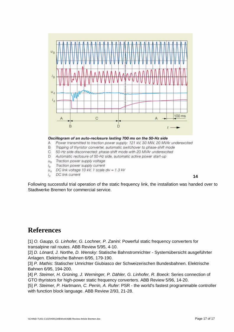
The oscillogram in Image 14 shows, as an example, the DC link voltage, DC link current andvoltage, and current at the point of connection of the traction power supply during switching fromnormal transmission to phase shift mode. This sequence is switched on automatically wheneverthere is a disturbance in the three-phase AC system. The reversal sequence (right-hand side of theoscillogram) is also automatic, being carried out as soon as the AC network conditions have beenrestored to normal.
\\CHIND-TU01-C102\H09134$\Work\ABB Review Article Bremen.doc Page 17 of 17
14
Following successful trial operation of the static frequency link, the installation was handed over toStadtwerke Bremen for commercial service.
References[1] O. Gaupp, G. Linhofer, G. Lochner, P. Zanini: Powerful static frequency converters fortransalpine rail routes. ABB Review 5/95, 4-10.[2] D. Lönard, J. Northe, D. Wensky: Statische Bahnstromrichter - Systemübersicht ausgeführterAnlagen. Elektrische Bahnen 6/95, 179-190.[3] P. Mathis: Statischer Umrichter Giubiasco der Schweizerischen Bundesbahnen. ElektrischeBahnen 6/95, 194-200.[4] P. Steimer, H. Grüning, J. Werninger, P. Dähler, G. Linhofer, R. Boeck: Series connection ofGTO thyristors for high-power static frequency converters. ABB Review 5/96, 14-20.[5] P. Steimer, P. Hartmann, C. Perrin, A. Rufer: PSR - the world's fastest programmable controllerwith function block language. ABB Review 2/93, 21-28.