BLUE LINE ll Tanks - REWATEC
24
BLUE LINE ll Tanks Technische Dokumentation Unterirdische Universalspeicher BlueLine II (Seite 2 -12) Technical documentation Underground container BlueLine II (Page 13 -23)
Transcript of BLUE LINE ll Tanks - REWATEC

BLUE LINE ll Tanks
Technische Dokumentation Unterirdische Universalspeicher BlueLine II
(Seite 2 -12)
Technical documentation Underground container BlueLine II
(Page 13 -23)

Premier Tech Aqua • Rewatec® 2/24 Blue Line II Tanks DORW2046a – 22.09.2016
Technische Dokumentation Unterirdische Universalspeicher BlueLine II
Inhaltsübersicht
1. Standort ................................................................................................................................. 2
2. Installation .............................................................................................................................. 4
3. Installationsanleitungen .......................................................................................................... 5
4. Hauptabmessungen und Lage der Standard-Anschlussöffnungen ......................................... 9
5. Zubehör optional .................................................................................................................. 11
1. Standort
1.1 Lage zu Gebäuden
Die Baugrube darf einen Mindestabstand zu Gebäuden nicht unterschreiten. Der Tank darf nur
überbaut werden, wenn die auftretenden Lasten nicht höher sind als die Verkehrslasten.
1.2 Bodenverhältnisse
Die Tanks dürfen maximal bis zu einem Drittel ihrer „Schulterhöhe“ (siehe Abbildungen unter
Punkt 4) in Grund-/bzw. Schichtenwasser eintauchen. Bei suspendiertem („verflüssigtem“)
Lehmboden darf die Eintauchtiefe nicht mehr als 250 mm betragen.
1.3 Hanglage
Das Gelände ist auf Rutschungsgefahr des Erdreichs zu prüfen (DIN 1054 Ausgabe 1/2003, E
DIN 4084 Ausgabe 11/2002) und gegebenenfalls mit einer Stützkonstruktion (z.B. einer Mauer)
zu stabilisieren. Informationen dazu gibt es bei örtlichen Behörden und Baufirmen.

Premier Tech Aqua • Rewatec® 3/24 Blue Line II Tanks DORW2046a – 22.09.2016
1.4 Verkehrsverhältnisse
Belastungsklasse A15 (z.B. Fußgänger, Radfahrer): keine besondere Ausstattung nötig.
Belastungsklasse B (PKW, Kleinbus, max. Gesamtgewicht 3,5 t - max. Achslast 2,2 t): Siehe
Einbauanleitung für Schachtverlängerung DORW3051. Mindestabstand 600 mm zwischen
Schulterhöhe Tank und Oberkante Fahrbahnbelag.
Belastungsklassen D (LKW, max. Gesamtgewicht 40 t – max. Achslast 11,5 t): Zwischenring
nötig, weitere Information in Anleitung DORW2127. Mindestabstand 800 mm zwischen
Schulterhöhe Tank und Oberkante Fahrbahnbelag.
1.5 Weitere Kriterien
Vorhandene Leitungen, Rohre, Vegetation sowie andere Besonderheiten sind so zu
berücksichtigen, dass Beeinträchtigungen und Gefährdungen vermieden werden. Die
Erdüberdeckung ab Tankschulter darf maximal 1,5 m betragen.

Premier Tech Aqua • Rewatec® 4/24 Blue Line II Tanks DORW2046a – 22.09.2016
2. Installation
2.1 Verfüllmaterial am Tank (Umhüllung, Bettung)
Das Verfüllmaterial muss gut verdichtbar und wasserdurchlässig sein, eine feste Packung bilden
und darf die Tankoberfläche nicht beschädigen. Wenn das Verfüllmaterial scharfkantige und/oder
spitze Bestandteile enthält, ist die Tankwand durch eine Sandumhüllung zu schützen.
Rundkornkies - unsere Empfehlung!
Maximale Körnung 8/16 mm
(alternativ z.B.: 12/16 mm oder 8/12 mm)
Positive Eigenschaften
Gut zu verarbeiten
Kies ist weitestgehend selbstverdichtend
Vermeidung von Hohlräumen
Das Material wird lose geschüttet und verdichtet sich durch mechanisches Nachstochern
insbesondere in den Durchzügen bei den Flachtanks und den unteren Zwickeln bei BlueLine II
und NEO-Tanks
Leichter als Füllsand
Nimmt kein Wasser auf. Gute Ableitung von Stau- oder Schichtenwasser
Sehr hohe Stützkraft
Kann auch von Nicht-Fachleuten verbaut werden
Anderes Verfüllmaterial kann im Einzelfall verwendet werden. Hierzu das technische Merkblatt
DORW0100 „Verfüllmaterial gültig für alle Premier Tech Aqua / REWATEC Behälter“.
Siehe www.premiertechaqua.com
2.2 Verfüllung außerhalb der Umhüllung des Tanks
Es kann Aushub oder anderes Material verwendet werden, das ausreichend stabil und
sickerfähig ist.
2.3 Verfüll- Verdichtungsmethoden
Die anzuwendenden Verfüll- und Verdichtungsmethoden sind in Kapitel 3 beschrieben
(Installationsanleitung)
Zu den nicht anzuwendenden Methoden gehört insbesondere das Einschlämmen. Es wird
keine Verdichtung erreicht und das Korngemisch entmischt sich, so dass keine stabile Packung
entsteht.
Tragschicht befahrbare Version: Es ist Gestein des Korngrößenbereichs 2/45 zu verwenden.
2.4 Leitungen
- Die Zulaufleitung sollte mit Gefälle zum Tank verlegt werden (>1%).
- Eine Überlaufleitung bzw. Ablaufleitung sollte ein stärkeres Gefälle vom Tank weg aufweisen,
als das der Zulaufleitung zum Tank hin.
- Eine Versorgungsleitung ist so zu gestalten, dass ein Überfluten eines angeschlossenen
Aggregatraums (z.B. Keller) bei (über-)vollem Tank vermieden wird.
Dieses kann beispielsweise realisiert werden durch ein ausreichend starkes Gefälle der Leitung
vom Haus zum Tank. Oder die Installation einer Abdichtung.- Die Leitungen sind so einzubauen,
dass Frostsicherheit gewährleistet ist. Dieses ist entsprechend den örtlichen klimatischen
Verhältnissen, gegebenenfalls in Abstimmung mit den Behörden, festzulegen.

Premier Tech Aqua • Rewatec® 5/24 Blue Line II Tanks DORW2046a – 22.09.2016
3. Installationsanleitungen

Premier Tech Aqua • Rewatec® 6/24 Blue Line II Tanks DORW2046a – 22.09.2016
WICHTIG: Zu Beginn des Einbaus mit 500L Wasser befüllen. Danach Verfüllmaterial lagenweise um den Tank herum verdichten (siehe Bild 10, 11) Bei Retentionszisternen muss der Ablauf vorübergehend verhindert werden. Z.B durch hochbinden der Ablaufdrossel.

Premier Tech Aqua • Rewatec® 7/24 Blue Line II Tanks DORW2046a – 22.09.2016
Wichtig:Bei Retentionszisternen muss der Ablauf vorübergehend verhindert werden. Z.B durch hochbinden der Ablaufdrossel.

Premier Tech Aqua • Rewatec® 8/24 Blue Line II Tanks DORW2046a – 22.09.2016
Wichtig:Bei Retentionszisternen muss der Ablauf vorübergehend verhindert werden. Z.B durch hochbinden der Ablaufdrossel.
Premier Tech Aqua • Rewatec® 9/24 Blue Line II Tanks DORW2046a – 22.09.2016
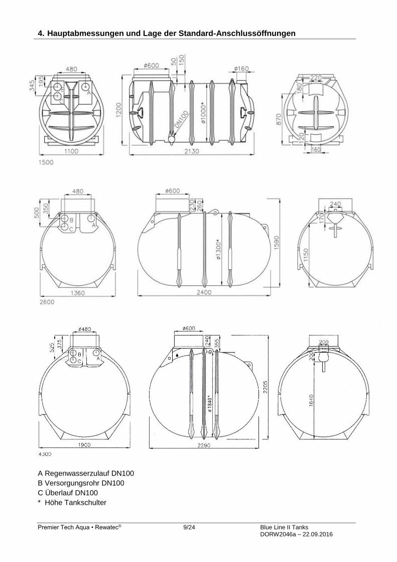
4. Hauptabmessungen und Lage der Standard-Anschlussöffnungen
A Regenwasserzulauf DN100
B Versorgungsrohr DN100
C Überlauf DN100
* Höhe Tankschulter
Premier Tech Aqua • Rewatec® 10/24 Blue Line II Tanks DORW2046a – 22.09.2016
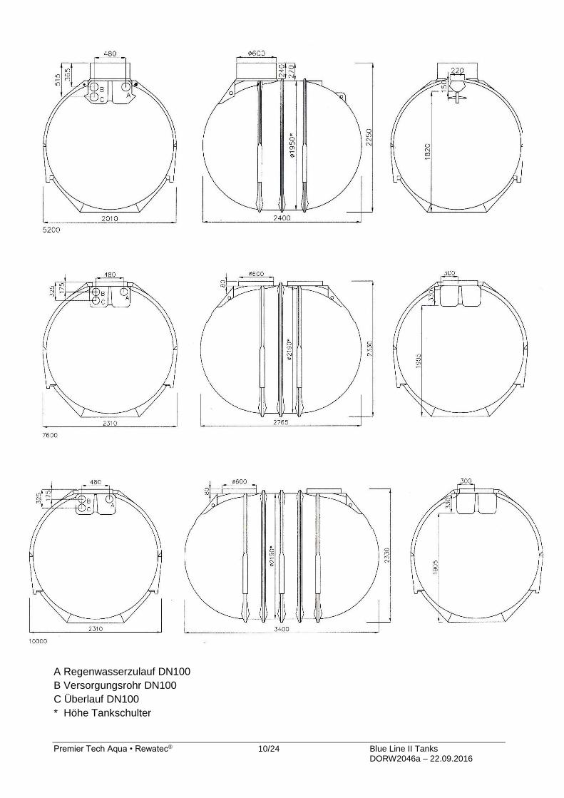
A Regenwasserzulauf DN100
B Versorgungsrohr DN100
C Überlauf DN100
* Höhe Tankschulter

Premier Tech Aqua • Rewatec® 11/24 Blue Line II Tanks DORW2046a – 22.09.2016
5. Zubehör optional
5.1 Verlängerungsschächte VS60 und VS20 (durch Zuschneiden kürzbar)
VS 60 verlängert netto bis 600mm
VS 20 Verlängert netto bis 200mm
Hinweis: Bitte die Einbauanleitung
des Erdtanks bezüglich der
Einbautiefe beachten!
5.2 Schachtabdeckung TopCover nach DIN 1989
Kunststoffabdeckung begehbar für 600er Schachtsysteme mit integriertem Sicherungsriegel nach
EN 10981. Außendurchmesser 648 mm, nach DIN 19596
A Sicherungsriegel geschlossen B Sicherungsriegel geöffnet
5.3 Schachtabdeckung Twin Cover nach DIN 1989
Abdeckung aus Kunststoff, begehbar, für 600er Schachtsysteme mit Sicherungsriegel nach EN
10891 und integrierter Inspektionsöffnung, die durch Verschraubung gesichert werden kann.
Außendurchmesser 648 mm und Profil nach DIN 19596
A1 Inspektionsöffnung geschlossen A2 Inspektionsöffnung geöffnet B1 Sicherungsriegel geöffnet B2 Sicherungsriegel geschlossen

Premier Tech Aqua • Rewatec® 12/24 Blue Line II Tanks DORW2046a – 22.09.2016
5.4 PKW-Komplett Set
Stahldeckel
Verlängerungsschacht BS60
Zwischenring (auch einzeln erhältlich) Verlängert bis max.550mm
Hinweis: Bitte die Einbauanleitung des Erdtanks bezüglich der Einbautiefe beachten!
www.premiertechaqua.de
Technische Änderungen und Rechte vorbehalten. Keine Haftung für Druckfehler. Die Inhalte der technischen Dokumentation sind Bestandteil der Garantiebedingungen
Es sind bei Planung und Einbau die einschlägigen Normen und andere Regelwerke sowie die Unfallverhütungsvorschriften zu beachten.

Premier Tech Aqua • Rewatec® 13/24 Blue Line II Tanks DORW2046a – 22.09.2016
Technical documentation Underground container BlueLine II
Contents
1. Location ............................................................................................................................... 13
2. Installation ............................................................................................................................ 15
3. Installation guide .................................................................................................................. 16
4. Main dimensions and positions of the standard connections ................................................ 20
5. Accessories optionally .......................................................................................................... 22
1. Location
1.1 Position to buildings
The excavation hole must not located within a minimum distance to buildings.The tank may be
built over only if the appearing loads are not higher than the traffic loads.
1.2 Ground conditions
The tanks may be installed up to a maximum of one third of their "shoulder height" (see figures
under point 4) in ground water respectively layer water. With suspended ("liquefied") clay/silt
ground the depth may not exceed 250mm.
1.3 Hillside situation
The soil of the area has to be checked for possible soil movement (DIN 1054 edition 1/2003
E DIN 4084 edition 11/2002) and if necessary it will be need to secured with a supporting
structure (e.g. a wall). Further information is available at the local public authorities and building
enterprises.
Premier Tech Aqua • Rewatec® 14/24 Blue Line II Tanks DORW2046a – 22.09.2016
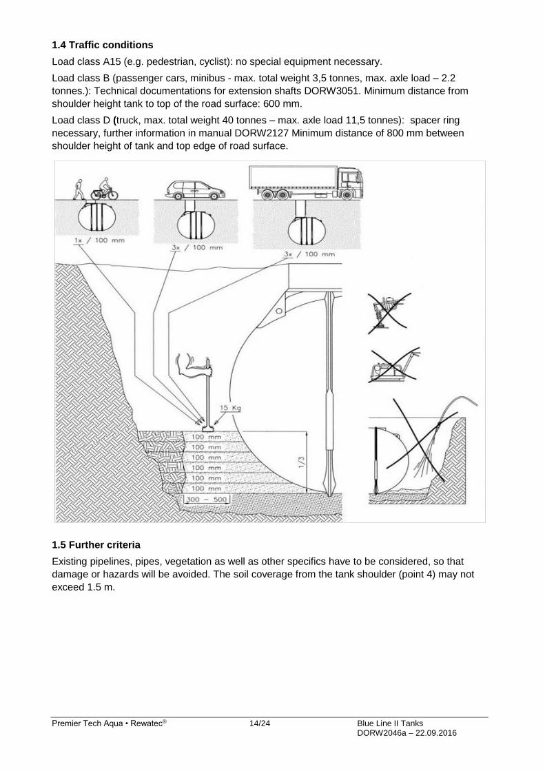
1.4 Traffic conditions
Load class A15 (e.g. pedestrian, cyclist): no special equipment necessary.
Load class B (passenger cars, minibus - max. total weight 3,5 tonnes, max. axle load – 2.2
tonnes.): Technical documentations for extension shafts DORW3051. Minimum distance from
shoulder height tank to top of the road surface: 600 mm.
Load class D (truck, max. total weight 40 tonnes – max. axle load 11,5 tonnes): spacer ring
necessary, further information in manual DORW2127 Minimum distance of 800 mm between
shoulder height of tank and top edge of road surface.
1.5 Further criteria
Existing pipelines, pipes, vegetation as well as other specifics have to be considered, so that
damage or hazards will be avoided. The soil coverage from the tank shoulder (point 4) may not
exceed 1.5 m.

Premier Tech Aqua • Rewatec® 15/24 Blue Line II Tanks DORW2046a – 22.09.2016
2. Installation
2.1 Backfill material at the tank (backfill, bedding)
The Backfill material must be able to be tightly compacted and must be permeable to water; it
must create a solid packing and may not damage the surface of the tank. If the backfill material
includes pieces with sharp or pointed edges, the tank walls must be protected with a sand
coating.
Round gravel – Our recommendation!
Maximum grain size of 8/16 mm
(alternatively e.g.: 12/16 mm or 8/12 mm)
Positive properties
Easy to work with
Gravel self-compacts extremely well
Prevents cavities
The material is strewn loosely and then compacts itself when prodded mechanically, especially
in the holes in the flat tanks and at the lower interstices in BlueLine II and NEO tanks
Lighter than filling sand
Does not absorb water Good drainage of accumulated water or water from high water tables
Very high supporting force
Can be installed by non-experts
Other backfill material can be used in individual cases.
For information regarding this, please refer to the technical information sheet: “DORW0100
backfill material valid for Premier Tech Aqua / REWATEC containers”; available on our website:
www.premiertechaqua.com
2.2 Filling beyond the backfill: Excavated soil or other material can be used if this is stable and
permeable.
2.3 Backfilling and compaction methods: The backfilling and compaction methods to be used
are described in Section 3 (Installation instructions)
Methods that are not to be used include in particular adding water. Adequate compaction is not
achieved and the mixture of particle sizes combine in such a way that the compaction is unstable.
Base layer (driveable version) Range of grain size 2/45 is to be used.
2.4 Pipes
- The feed pipe should be laid with a fall to the tank (>1%)
The overflow / drain pipe should have a deeper fall away from the tank than the fall from the feed
pipe to the tank.
- The service pipe is to be installed to prevent any flooding from the tank entering the service
room (e.g., cellar) if the tank is full. This can be achieved, for example, by a high enough incline
of the pipe from the house to the tank. Or by the installation of a seal.
- The pipes have to be installed in such a way that frost damage is avoided. This is to be
arranged according to the local climatic circumstances, if necessary in co-ordination with the local
authorities.

Premier Tech Aqua • Rewatec® 16/24 Blue Line II Tanks DORW2046a – 22.09.2016
3. Installation guide

Premier Tech Aqua • Rewatec® 17/24 Blue Line II Tanks DORW2046a – 22.09.2016
Important: At the start fill the tank with 500L of water. Afterwords use the filling material in layers around the tank and then compress the loose filling material (s.picture 10, 11) For retention cisterns, outflow must be temporarily halted, for example, by fixing the outflow throttle valve in a raised position.

Premier Tech Aqua • Rewatec® 18/24 Blue Line II Tanks DORW2046a – 22.09.2016
Important: For retention cisterns, outflow must be temporarily halted, for example, by fixing the outflow throttle valve in a raised position.

Premier Tech Aqua • Rewatec® 19/24 Blue Line II Tanks DORW2046a – 22.09.2016
Important: For retention cisterns, outflow must be temporarily halted, for example, by fixing the outflow throttle valve in a raised position.

Premier Tech Aqua • Rewatec® 20/24 Blue Line II Tanks DORW2046a – 22.09.2016
4. Main dimensions and positions of the standard connections
A Connection inflow DN100
B Connection service pipe DN100
C Connection overflow DN100
* height tank shoulder

Premier Tech Aqua • Rewatec® 21/24 Blue Line II Tanks DORW2046a – 22.09.2016
A Connection inflow DN100
B Connection service pipe DN100
C Connection overflow DN100
* height tank shoulder

Premier Tech Aqua • Rewatec® 22/24 Blue Line II Tanks DORW2046a – 22.09.2016
5. Accessories optionally
5.1 Extension shafts VS60 und VS20 (can be shortened by cutting)
VS 60 lengthens° up to 600mm
VS 20 lengthens° up to 200mm
Note: When purchasing this article please refer to the appropriate installation manual for the installation depth.
5.2 Shaft coverage TopCover according to DIN 1989
Walk-on Plastic Cover, for 600mm shaft-systems with safety latch according to EN 10891.
External diameter 648 and profile according to DIN 19596.
A Safety latch opened B Safety latch closed
5.3 Shaft coverage TwinCover according to DIN 1989
Walk-on Plastic Cover, for 600mm shaft-systems with safety latch according to EN 10891 and
integrated inspection opening, which is lockable.
External diameter 648 mm and profile according to DIN 19596.
A1 inspection opening closed A2 inspection opening open B1 safety latch opened B2 safety latch closed

Premier Tech Aqua • Rewatec® 23/24 Blue Line II Tanks DORW2046a – 22.09.2016
5.4 Car set complete
Steel cover
Extension shaft BS60
Spacer ring (also individually available) Lengthens°up to max. 550mm
Note: When purchasing this article please refer to the appropriate installation manual for the installation depth.
www.premiertechaqua.de Technical changes and rights reserved. No liability for misprints
The contents of the technical documentation are a component of the guarantee terms
Planning and installation regulations are to be followed, as well as the accident prevention regulations.

Premier Tech Aqua • Rewatec® 24/24 Blue Line II Tanks DORW2046a – 22.09.2016
Premier Tech Aqua GmbH Telefonische Fachberatung: +49-(0)38847-6239-0
www.premiertechaqua.de [email protected]