Fr laserclad revetements laser rechargements laser fabrication poudres laser
* corresponding author
BIM FROM LASER SCANS… NOT JUST FOR BUILDINGS:
NURBS-BASED PARAMETRIC MODELING OF A MEDIEVAL BRIDGE
L. Barazzetti*, F. Banfi, R. Brumana, M. Previtali, F. Roncoroni
ABC Department, Politecnico di Milano, Piazza Leonardo da Vinci 32, Milan, Italy
(luigi.barazzetti, fabrizio.banfi, raffaella.brumana, mattia.previtali, fabio.roncoroni)@polimi.it
http://www.gicarus.polimi.it
KEY WORDS: BIM, BIMonitoring, Interoperability, Laser Scanning, Photogrammetry, Monitoring, NURBS
ABSTRACT:
Building Information Modelling is not limited to buildings. BIM technology includes civil infrastructures such as roads, dams, bridges,
communications networks, water and wastewater networks and tunnels. This paper describes a novel methodology for the generation
of a detailed BIM of a complex medieval bridge. The use of laser scans and images coupled with the development of algorithms able
to handle irregular shapes allowed the creation of advanced parametric objects, which were assembled to obtain an accurate BIM. The
lack of existing object libraries required the development of specific families for the different structural elements of the bridge. Finally,
some applications aimed at assessing the stability and safety of the bridge are illustrated and discussed. The BIM of the bridge can
incorporate this information towards a new “BIMonitoring” concept.
to preserve the geometric complexity provided by point clouds, obtaining a detailed BIM with object relationships and attributes.
1. INTRODUCTION
Building Information Modelling is becoming a very popular
technology for several infrastructures such as utility systems,
roads and rails, bridges, dams, tunnels, communications
networks, water and wastewater networks, etc. This fosters the
use of advanced digital models (including semantics, object
relationships and attributes) instead of traditional construction
projects still based on 2D and 2D CAD drawings. However, BIM
technology has limitations, especially for complex constructions
with and irregular constructive elements. This is a significant
problem for both modern and existing constructions (Agapiou et
al., 2015, Patraucean et al., 2015; Tang et al., 2010; Volk et al.,
2014, Cuca et al., 2015).
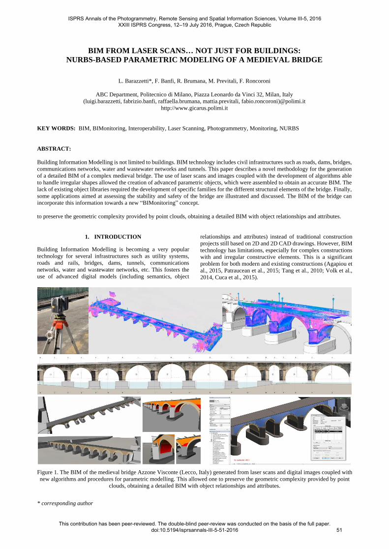
Figure 1. The BIM of the medieval bridge Azzone Visconte (Lecco, Italy) generated from laser scans and digital images coupled with
new algorithms and procedures for parametric modelling. This allowed one to preserve the geometric complexity provided by point
clouds, obtaining a detailed BIM with object relationships and attributes.
ISPRS Annals of the Photogrammetry, Remote Sensing and Spatial Information Sciences, Volume III-5, 2016 XXIII ISPRS Congress, 12–19 July 2016, Prague, Czech Republic
This contribution has been peer-reviewed. The double-blind peer-review was conducted on the basis of the full paper. doi:10.5194/isprsannals-III-5-51-2016
51
* corresponding author
This paper focuses on BIM for bridges (sometimes referred to
BrIM - Bridge Information Modelling), which is a novel
approach able to manage the whole lifecycle of a bridge:
fabrication, construction, operation, maintenance and inspection.
The case study presented in this work is the medieval bridge
Azzone Visconte (also known as the Old Bridge) over the Adda
River, in Lecco (Italy). The bridge was built between 1336 and
1338 and today is the symbol of the city (Fig. 2). Several analyses
were carried out to assess the stability and safety of the bridge, as
well as the state of conservation of materials and structures.
A geometrical survey at the scale 1:50 was one of the required
products of the project. The complex and irregular geometry of
the bridge resulted in several limitations when the modelling
tools in BIM software packages were used. It should be
mentioned that this “geometric” problem is not limited to historic
objects. It also includes new bridges often characterized by
variable curvature and cross sections. From this point of view,
the lack of powerful BIM instruments able to reconstruct
complex shapes is still a major drawback in BIM projects, and
the generation of accurate historic BIM (Murphy et al., 2013)
surveyed from laser scanning point clouds is a challenging task
which requires the development of new libraries or the
implementation of new algorithms (some examples are discussed
in Fai et al., 2011; Baik et al., 2015; Oreni et al., 2014; Dore et
al., 2015; Quattrini et al., 2015, Barazzetti et al., 2015c).
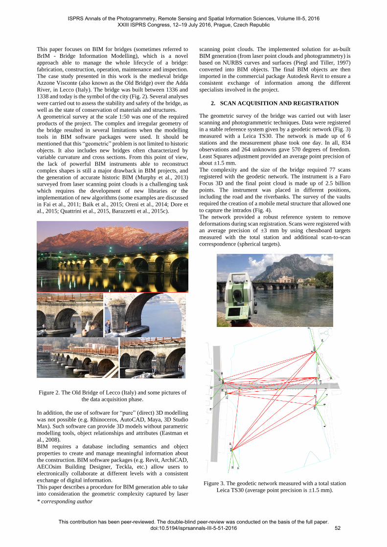
Figure 2. The Old Bridge of Lecco (Italy) and some pictures of
the data acquisition phase.
In addition, the use of software for “pure” (direct) 3D modelling
was not possible (e.g. Rhinoceros, AutoCAD, Maya, 3D Studio
Max). Such software can provide 3D models without parametric
modelling tools, object relationships and attributes (Eastman et
al., 2008).
BIM requires a database including semantics and object
properties to create and manage meaningful information about
the construction. BIM software packages (e.g. Revit, ArchiCAD,
AECOsim Building Designer, Teckla, etc.) allow users to
electronically collaborate at different levels with a consistent
exchange of digital information.
This paper describes a procedure for BIM generation able to take
into consideration the geometric complexity captured by laser
scanning point clouds. The implemented solution for as-built
BIM generation (from laser point clouds and photogrammetry) is
based on NURBS curves and surfaces (Piegl and Tiller, 1997)
converted into BIM objects. The final BIM objects are then
imported in the commercial package Autodesk Revit to ensure a
consistent exchange of information among the different
specialists involved in the project.
2. SCAN ACQUISITION AND REGISTRATION
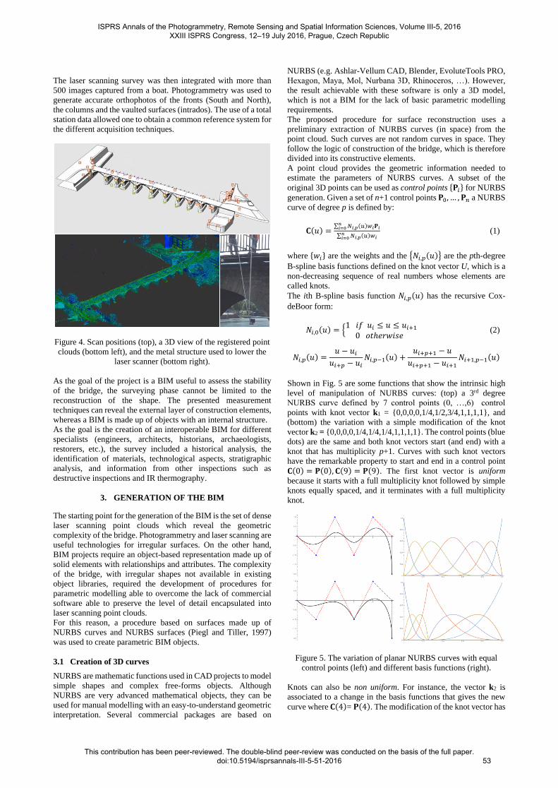
The geometric survey of the bridge was carried out with laser
scanning and photogrammetric techniques. Data were registered
in a stable reference system given by a geodetic network (Fig. 3)
measured with a Leica TS30. The network is made up of 6
stations and the measurement phase took one day. In all, 834
observations and 264 unknowns gave 570 degrees of freedom.
Least Squares adjustment provided an average point precision of
about ±1.5 mm.
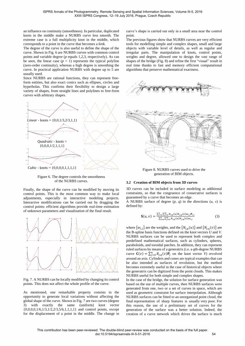
The complexity and the size of the bridge required 77 scans
registered with the geodetic network. The instrument is a Faro
Focus 3D and the final point cloud is made up of 2.5 billion
points. The instrument was placed in different positions,
including the road and the riverbanks. The survey of the vaults
required the creation of a mobile metal structure that allowed one
to capture the intrados (Fig. 4).
The network provided a robust reference system to remove
deformations during scan registration. Scans were registered with
an average precision of ±3 mm by using chessboard targets
measured with the total station and additional scan-to-scan
correspondence (spherical targets).
Figure 3. The geodetic network measured with a total station
Leica TS30 (average point precision is ±1.5 mm).
ISPRS Annals of the Photogrammetry, Remote Sensing and Spatial Information Sciences, Volume III-5, 2016 XXIII ISPRS Congress, 12–19 July 2016, Prague, Czech Republic
This contribution has been peer-reviewed. The double-blind peer-review was conducted on the basis of the full paper. doi:10.5194/isprsannals-III-5-51-2016
52
The laser scanning survey was then integrated with more than
500 images captured from a boat. Photogrammetry was used to
generate accurate orthophotos of the fronts (South and North),
the columns and the vaulted surfaces (intrados). The use of a total
station data allowed one to obtain a common reference system for
the different acquisition techniques.
Figure 4. Scan positions (top), a 3D view of the registered point
clouds (bottom left), and the metal structure used to lower the
laser scanner (bottom right).
As the goal of the project is a BIM useful to assess the stability
of the bridge, the surveying phase cannot be limited to the
reconstruction of the shape. The presented measurement
techniques can reveal the external layer of construction elements,
whereas a BIM is made up of objects with an internal structure.
As the goal is the creation of an interoperable BIM for different
specialists (engineers, architects, historians, archaeologists,
restorers, etc.), the survey included a historical analysis, the
identification of materials, technological aspects, stratigraphic
analysis, and information from other inspections such as
destructive inspections and IR thermography.
3. GENERATION OF THE BIM
The starting point for the generation of the BIM is the set of dense
laser scanning point clouds which reveal the geometric
complexity of the bridge. Photogrammetry and laser scanning are
useful technologies for irregular surfaces. On the other hand,
BIM projects require an object-based representation made up of
solid elements with relationships and attributes. The complexity
of the bridge, with irregular shapes not available in existing
object libraries, required the development of procedures for
parametric modelling able to overcome the lack of commercial
software able to preserve the level of detail encapsulated into
laser scanning point clouds.
For this reason, a procedure based on surfaces made up of
NURBS curves and NURBS surfaces (Piegl and Tiller, 1997)
was used to create parametric BIM objects.
3.1 Creation of 3D curves
NURBS are mathematic functions used in CAD projects to model
simple shapes and complex free-forms objects. Although
NURBS are very advanced mathematical objects, they can be
used for manual modelling with an easy-to-understand geometric
interpretation. Several commercial packages are based on
NURBS (e.g. Ashlar-Vellum CAD, Blender, EvoluteTools PRO,
Hexagon, Maya, Mol, Nurbana 3D, Rhinoceros, …). However,
the result achievable with these software is only a 3D model,
which is not a BIM for the lack of basic parametric modelling
requirements.
The proposed procedure for surface reconstruction uses a
preliminary extraction of NURBS curves (in space) from the
point cloud. Such curves are not random curves in space. They
follow the logic of construction of the bridge, which is therefore
divided into its constructive elements.
A point cloud provides the geometric information needed to
estimate the parameters of NURBS curves. A subset of the
original 3D points can be used as control points {𝐏𝑖} for NURBS
generation. Given a set of n+1 control points 𝐏0, … , 𝐏𝑛 a NURBS
curve of degree p is defined by:
𝐂(𝑢) =∑ 𝑁𝑖,𝑝(𝑢)𝑤𝑖𝐏𝑖
𝑛𝑖=0
∑ 𝑁𝑖,𝑝(𝑢)𝑤𝑖𝑛𝑖=0
(1)
where {𝑤𝑖} are the weights and the {𝑁𝑖,𝑝(𝑢)} are the pth-degree
B-spline basis functions defined on the knot vector U, which is a
non-decreasing sequence of real numbers whose elements are
called knots.
The ith B-spline basis function 𝑁𝑖,𝑝(𝑢) has the recursive Cox-
deBoor form:
𝑁𝑖,0(𝑢) = {1 𝑖𝑓 𝑢𝑖 ≤ 𝑢 ≤ 𝑢𝑖+1
0 𝑜𝑡ℎ𝑒𝑟𝑤𝑖𝑠𝑒 (2)
𝑁𝑖,𝑝(𝑢) =𝑢 − 𝑢𝑖
𝑢𝑖+𝑝 − 𝑢𝑖𝑁𝑖,𝑝−1(𝑢) +
𝑢𝑖+𝑝+1 − 𝑢
𝑢𝑖+𝑝+1 − 𝑢𝑖+1𝑁𝑖+1,𝑝−1(𝑢)
Shown in Fig. 5 are some functions that show the intrinsic high
level of manipulation of NURBS curves: (top) a 3rd degree
NURBS curve defined by 7 control points (0, …,6) control
points with knot vector k1 = {0,0,0,0,1/4,1/2,3/4,1,1,1,1}, and
(bottom) the variation with a simple modification of the knot
vector k2 = {0,0,0,0,1/4,1/4,1/4,1,1,1,1}. The control points (blue
dots) are the same and both knot vectors start (and end) with a
knot that has multiplicity p+1. Curves with such knot vectors
have the remarkable property to start and end in a control point
𝐂(0) = 𝐏(0), 𝐂(9) = 𝐏(9). The first knot vector is uniform
because it starts with a full multiplicity knot followed by simple
knots equally spaced, and it terminates with a full multiplicity
knot.
Figure 5. The variation of planar NURBS curves with equal
control points (left) and different basis functions (right).
Knots can also be non uniform. For instance, the vector k2 is
associated to a change in the basis functions that gives the new
curve where 𝐂(4)= 𝐏(4). The modification of the knot vector has
ISPRS Annals of the Photogrammetry, Remote Sensing and Spatial Information Sciences, Volume III-5, 2016 XXIII ISPRS Congress, 12–19 July 2016, Prague, Czech Republic
This contribution has been peer-reviewed. The double-blind peer-review was conducted on the basis of the full paper. doi:10.5194/isprsannals-III-5-51-2016
53
an influence on continuity (smoothness). In particular, duplicated
knots in the middle make a NURBS curve less smooth. The
extreme case is a full multiplicity knot in the middle, which
corresponds to a point in the curve that becomes a kink.
The degree of the curve is also useful to define the shape of the
curve. Shown in Fig. 6 are NURBS curves with common control
points and variable degree (p equals 1,2,3, respectively). As can
be seen, the linear case (p = 1) represents the typical polyline
(zero-order continuity), whereas a high degree is smoothing the
curve. In practical application NURBS with degree up to 5 are
usually used.
Since NURBS are rational functions, they can represent free-
form entities, but also exact conics such as ellipses, circles and
hyperbolas. This confirms their flexibility to design a large
variety of shapes, from straight lines and polylines to free-form
curves with arbitrary shapes.
Linear - knots = {0,0,1/3,2/3,1,1}
Quadratic - knots =
{0,0,0,1/2,1,1,1}
Cubic - knots = {0,0,0,0,1,1,1,1}
Figure 6. The degree controls the smoothness
of the NURBS curves.
Finally, the shape of the curve can be modified by moving its
control points. This is the most common way to make local
adjustments, especially in interactive modeling projects.
Interactive modifications can be carried out by dragging the
control points: efficient algorithms provide real-time estimation
of unknown parameters and visualization of the final result.
Fig. 7. A NURBS can be locally modified by changing its control
points. This does not affect the whole profile of the curve.
As mentioned, one remarkable property consists in the
opportunity to generate local variations without affecting the
global shape of the curve. Shown in Fig. 7 are two curves (degree
3) with exactly the same (uniform) knot vector
{0,0,0,0,1/6,1/3,1/2,2/3,5/6,1,1,1,1} and control points, except
for the displacement of a point in the middle. The change in
curve’s shape is carried out only in a small area near the control
point.
The previous figures show that NURBS curves are very efficient
tools for modelling simple and complex shapes, small and large
objects with variable level of details, as well as regular and
irregular parts. The manipulation of knots, control points,
weights and degree, allowed one to design the vast range of
shapes of the bridge (Fig. 8) and refine the first “visual” result in
real time thanks to fast and memory efficient computational
algorithms that preserve mathematical exactness.
Figure 8. NURBS curves used to drive the
generation of BIM objects.
3.2 Creation of BIM objects from 3D curves
3D curves can be included in surface modeling as additional
constraints, so that the congruence of consecutive surfaces is
guaranteed by a curve that becomes an edge.
A NURBS surface of degree (p, q) in the directions (u, v) is
defined by:
𝐒(𝑢, 𝑣) =∑ ∑ 𝑁𝑖,𝑝(𝑢)𝑁𝑗,𝑞(𝑣)𝑤𝑖,𝑗𝐏𝑖,𝑗
𝑚𝑗=0
𝑛𝑖=0
∑ ∑ 𝑁𝑖,𝑝(𝑢)𝑁𝑗,𝑞(𝑣)𝑤𝑖,𝑗𝑚𝑗=0
𝑛𝑖=0
(3)
where {𝑤𝑖,𝑗} are the weights, and the {𝑁𝑖,𝑝(𝑢)} and {𝑁𝑗,𝑞(𝑣)} are
the B-spline basis functions defined on the knot vectors U and V. NURBS surfaces can be used to represent both complex and
predefined mathematical surfaces, such as cylinders, spheres,
paraboloids, and toroidal patches. In addition, they can represent
ruled surfaces by means of a generatrix (i.e. a qth-degree NURBS
curve 𝐂(𝑣) = ∑ 𝑅𝑗,𝑞(𝑣)𝐏𝑗𝑛𝑗=0 on the knot vector V) revolved
around an axis. Cylinders and cones are typical examples that can
be also intended as surfaces of revolution, but the method
becomes extremely useful in the case of historical objects where
the generatrix can be digitized from the point clouds. This makes
NURBS useful for both simple and complex shapes.
In the case of the bridge, the solution for surface generation was
based on the use of multiple curves, then NURBS surfaces were
generated from one, two or a set of curves in space, which are
used as geometric constraint for surface interpolation. Although
NURBS surfaces can be fitted to an unorganized point cloud, the
final representation of sharp features is usually very poor. For
this reason, the use of a preliminary set of curves for the
generation of the surface was a better solution. Indeed, the
creation of a curve network which drives the surface is much
ISPRS Annals of the Photogrammetry, Remote Sensing and Spatial Information Sciences, Volume III-5, 2016 XXIII ISPRS Congress, 12–19 July 2016, Prague, Czech Republic
This contribution has been peer-reviewed. The double-blind peer-review was conducted on the basis of the full paper. doi:10.5194/isprsannals-III-5-51-2016
54
easier than a direct manipulation of the surface, especially in the
case of discontinuity lines.
After the extraction of the principal discontinuities, which
provide the skeleton of a 3D shape, surfaces were generated with
an interpolation of the curves through one or more surfaces. The
curve should be interpolated as closely as possible so that the
distance between the curves, clouds, and final surface is
minimum (Hu et al., 2001; Brujic et al., 2002).
The reconstruction of the bridge included the preliminary
subdivision of the bridge into structural elements following the
logic of construction (how the bridge is actually built, such as
foundations, columns, arches, etc., see Brumana et al., 2013).
This process allows an accurate geometric representation of the
external shape surveyed with laser scanning technology and
photogrammetry. On the other hand, it does not provide BIM
objects for the lack of parametric modelling tools, relationships
between objects and attributes. In addition, point clouds reveal
precious metric information about the external first layer of the
different elements, i.e. the visible layer that can be surveyed with
images and range data, whereas a BIM must incorporate
additional information concerning volume (e.g. thickness),
material properties, and the organization of structural elements.
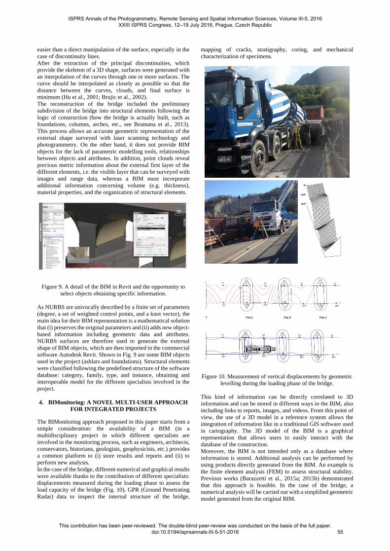
Figure 9. A detail of the BIM in Revit and the opportunity to
select objects obtaining specific information.
As NURBS are univocally described by a finite set of parameters
(degree, a set of weighted control points, and a knot vector), the
main idea for their BIM representation is a mathematical solution
that (i) preserves the original parameters and (ii) adds new object-
based information including geometric data and attributes.
NURBS surfaces are therefore used to generate the external
shape of BIM objects, which are then imported in the commercial
software Autodesk Revit. Shown in Fig. 9 are some BIM objects
used in the project (ashlars and foundations). Structural elements
were classified following the predefined structure of the software
database: category, family, type, and instance, obtaining and
interoperable model for the different specialists involved in the
project.
4. BIMonitoring: A NOVEL MULTI-USER APPROACH
FOR INTEGRATED PROJECTS
The BIMonitoring approach proposed in this paper starts from a
simple consideration: the availability of a BIM (in a
multidisciplinary project in which different specialists are
involved in the monitoring process, such as engineers, architects,
conservators, historians, geologists, geophysicists, etc.) provides
a common platform to (i) store results and reports and (ii) to
perform new analysis.
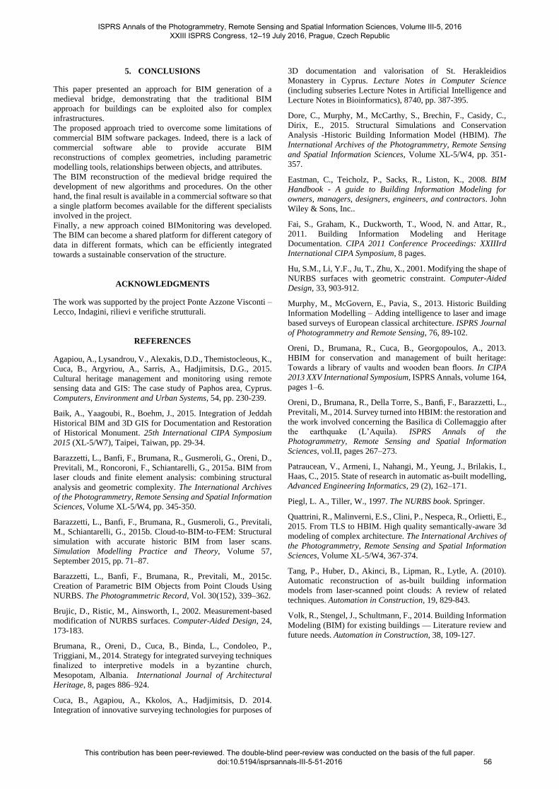
In the case of the bridge, different numerical and graphical results
were available thanks to the contribution of different specialists:
displacements measured during the loading phase to assess the
load capacity of the bridge (Fig. 10), GPR (Ground Penetrating
Radar) data to inspect the internal structure of the bridge,
mapping of cracks, stratigraphy, coring, and mechanical
characterization of specimens.
Figure 10. Measurement of vertical displacements by geometric
levelling during the loading phase of the bridge.
This kind of information can be directly correlated to 3D
information and can be stored in different ways in the BIM, also
including links to reports, images, and videos. From this point of
view, the use of a 3D model in a reference system allows the
integration of information like in a traditional GIS software used
in cartography. The 3D model of the BIM is a graphical
representation that allows users to easily interact with the
database of the construction.
Moreover, the BIM is not intended only as a database where
information is stored. Additional analysis can be performed by
using products directly generated from the BIM. An example is
the finite element analysis (FEM) to assess structural stability.
Previous works (Barazzetti et al., 2015a; 2015b) demonstrated
that this approach is feasible. In the case of the bridge, a
numerical analysis will be carried out with a simplified geometric
model generated from the original BIM.
ISPRS Annals of the Photogrammetry, Remote Sensing and Spatial Information Sciences, Volume III-5, 2016 XXIII ISPRS Congress, 12–19 July 2016, Prague, Czech Republic
This contribution has been peer-reviewed. The double-blind peer-review was conducted on the basis of the full paper. doi:10.5194/isprsannals-III-5-51-2016
55
5. CONCLUSIONS
This paper presented an approach for BIM generation of a
medieval bridge, demonstrating that the traditional BIM
approach for buildings can be exploited also for complex
infrastructures.
The proposed approach tried to overcome some limitations of
commercial BIM software packages. Indeed, there is a lack of
commercial software able to provide accurate BIM
reconstructions of complex geometries, including parametric
modelling tools, relationships between objects, and attributes.
The BIM reconstruction of the medieval bridge required the
development of new algorithms and procedures. On the other
hand, the final result is available in a commercial software so that
a single platform becomes available for the different specialists
involved in the project.
Finally, a new approach coined BIMonitoring was developed.
The BIM can become a shared platform for different category of
data in different formats, which can be efficiently integrated
towards a sustainable conservation of the structure.
ACKNOWLEDGMENTS
The work was supported by the project Ponte Azzone Visconti –
Lecco, Indagini, rilievi e verifiche strutturali.
REFERENCES
Agapiou, A., Lysandrou, V., Alexakis, D.D., Themistocleous, K.,
Cuca, B., Argyriou, A., Sarris, A., Hadjimitsis, D.G., 2015.
Cultural heritage management and monitoring using remote
sensing data and GIS: The case study of Paphos area, Cyprus.
Computers, Environment and Urban Systems, 54, pp. 230-239.
Baik, A., Yaagoubi, R., Boehm, J., 2015. Integration of Jeddah
Historical BIM and 3D GIS for Documentation and Restoration
of Historical Monument. 25th International CIPA Symposium
2015 (XL-5/W7), Taipei, Taiwan, pp. 29-34.
Barazzetti, L., Banfi, F., Brumana, R., Gusmeroli, G., Oreni, D.,
Previtali, M., Roncoroni, F., Schiantarelli, G., 2015a. BIM from
laser clouds and finite element analysis: combining structural
analysis and geometric complexity. The International Archives
of the Photogrammetry, Remote Sensing and Spatial Information
Sciences, Volume XL-5/W4, pp. 345-350.
Barazzetti, L., Banfi, F., Brumana, R., Gusmeroli, G., Previtali,
M., Schiantarelli, G., 2015b. Cloud-to-BIM-to-FEM: Structural
simulation with accurate historic BIM from laser scans.
Simulation Modelling Practice and Theory, Volume 57,
September 2015, pp. 71–87.
Barazzetti, L., Banfi, F., Brumana, R., Previtali, M., 2015c.
Creation of Parametric BIM Objects from Point Clouds Using
NURBS. The Photogrammetric Record, Vol. 30(152), 339–362.
Brujic, D., Ristic, M., Ainsworth, I., 2002. Measurement-based
modification of NURBS surfaces. Computer-Aided Design, 24,
173-183.
Brumana, R., Oreni, D., Cuca, B., Binda, L., Condoleo, P.,
Triggiani, M., 2014. Strategy for integrated surveying techniques
finalized to interpretive models in a byzantine church,
Mesopotam, Albania. International Journal of Architectural
Heritage, 8, pages 886–924.
Cuca, B., Agapiou, A., Kkolos, A., Hadjimitsis, D. 2014.
Integration of innovative surveying technologies for purposes of
3D documentation and valorisation of St. Herakleidios
Monastery in Cyprus. Lecture Notes in Computer Science
(including subseries Lecture Notes in Artificial Intelligence and
Lecture Notes in Bioinformatics), 8740, pp. 387-395.
Dore, C., Murphy, M., McCarthy, S., Brechin, F., Casidy, C.,
Dirix, E., 2015. Structural Simulations and Conservation
Analysis -Historic Building Information Model (HBIM). The
International Archives of the Photogrammetry, Remote Sensing
and Spatial Information Sciences, Volume XL-5/W4, pp. 351-
357.
Eastman, C., Teicholz, P., Sacks, R., Liston, K., 2008. BIM
Handbook - A guide to Building Information Modeling for
owners, managers, designers, engineers, and contractors. John
Wiley & Sons, Inc..
Fai, S., Graham, K., Duckworth, T., Wood, N. and Attar, R.,
2011. Building Information Modeling and Heritage
Documentation. CIPA 2011 Conference Proceedings: XXIIIrd
International CIPA Symposium, 8 pages.
Hu, S.M., Li, Y.F., Ju, T., Zhu, X., 2001. Modifying the shape of
NURBS surfaces with geometric constraint. Computer-Aided
Design, 33, 903-912.
Murphy, M., McGovern, E., Pavia, S., 2013. Historic Building
Information Modelling – Adding intelligence to laser and image
based surveys of European classical architecture. ISPRS Journal
of Photogrammetry and Remote Sensing, 76, 89-102.
Oreni, D., Brumana, R., Cuca, B., Georgopoulos, A., 2013.
HBIM for conservation and management of built heritage:
Towards a library of vaults and wooden bean floors. In CIPA
2013 XXV International Symposium, ISPRS Annals, volume 164,
pages 1–6.
Oreni, D., Brumana, R., Della Torre, S., Banfi, F., Barazzetti, L.,
Previtali, M., 2014. Survey turned into HBIM: the restoration and
the work involved concerning the Basilica di Collemaggio after
the earthquake (L’Aquila). ISPRS Annals of the
Photogrammetry, Remote Sensing and Spatial Information
Sciences, vol.II, pages 267–273.
Patraucean, V., Armeni, I., Nahangi, M., Yeung, J., Brilakis, I.,
Haas, C., 2015. State of research in automatic as-built modelling,
Advanced Engineering Informatics, 29 (2), 162–171.
Piegl, L. A., Tiller, W., 1997. The NURBS book. Springer.
Quattrini, R., Malinverni, E.S., Clini, P., Nespeca, R., Orlietti, E.,
2015. From TLS to HBIM. High quality semantically-aware 3d
modeling of complex architecture. The International Archives of
the Photogrammetry, Remote Sensing and Spatial Information
Sciences, Volume XL-5/W4, 367-374.
Tang, P., Huber, D., Akinci, B., Lipman, R., Lytle, A. (2010).
Automatic reconstruction of as-built building information
models from laser-scanned point clouds: A review of related
techniques. Automation in Construction, 19, 829-843.
Volk, R., Stengel, J., Schultmann, F., 2014. Building Information
Modeling (BIM) for existing buildings — Literature review and
future needs. Automation in Construction, 38, 109-127.
ISPRS Annals of the Photogrammetry, Remote Sensing and Spatial Information Sciences, Volume III-5, 2016 XXIII ISPRS Congress, 12–19 July 2016, Prague, Czech Republic
This contribution has been peer-reviewed. The double-blind peer-review was conducted on the basis of the full paper. doi:10.5194/isprsannals-III-5-51-2016
56