Ball Precision Multi Flutes ABP4F - mmc … type çÑ Ø çÓè³´ãïÚç½Ñç Ä "#1 ' Ball...
8
ABP4F type アルファ ボールプレシジョンマルチフルート ABP4F形 Ball Precision Multi Flutes ABP4F type New Product News No.1306 -4 2017-9 ボールプレシジョンマルチフルート Ball Precision Multi Flutes
Transcript of Ball Precision Multi Flutes ABP4F - mmc … type çÑ Ø çÓè³´ãïÚç½Ñç Ä "#1 ' Ball...
ABP4F typeアルファ ボールプレシジョンマルチフルート ABP4F形Ball Precision Multi Flutes ABP4F type
New Produc t News No.1306-4 2017-9
ボールプレシジョンマルチフルートBall Precision Multi Flutes

【注意】
【Note】
①部品はカッタ本体に付属しています。②部品類が損傷した場合、新しいものと交換してください。損傷した部品はインサート固定不良の原因になりますのでご注意ください。①Parts are included with the cutter body. ②When parts become damaged, replace them with new ones. Using damaged parts may result in improper mounting of inserts.
希望小売価格(円)Suggested
retail price(¥)
希望小売価格(円)Suggested
retail price(¥)
希望小売価格(円)Suggested
retail price(¥)
希望小売価格(円)Suggested
retail price(¥)
155-158
155-159
155-160
2.2
2.9
4.9
0.5
1.1
2
1,520
1,560
1,640
250-140
250-141
265-141
700
700
700
1,670
1,670
1,720
1,470
1,470
1,560
104-T15
104-T15
105-T20
A
A
B
A
A
A
P-37 820
104-T6
104-T8
104-T10
希望小売価格(円)Suggested
retail price(¥)
形状 Shape
部品名 Parts
適用カッタCutter body
クランプねじClamp screw
ドライバー/レンチScrew Driver / Wrench
A B
親刃Main insert
子刃Sub insert
親刃Main insert
形状Shape
形状Shape
子刃Sub insert
ねじ焼き付き防止剤
Screwanti-seizure agent
ABP4F20S20 L
ABP4F25S25 L
ABP4F30S32 L
締付トルクFastening
torque(N・m)
締付トルクFastening
torque(N・m)
ABP4F20S20WL80ABP4F20S20WL100ABP4F20S20WL120ABP4F25S25WL100ABP4F25S25WL120ABP4F25S25WL150ABP4F30S32WL100ABP4F30S32WL120ABP4F30S32WL150
ZDFG200SE
ZDFG250SE
ZDFG300SE
ZDFG200CE
ZDFG250CE
ZDFG300CE
●●●●●●●●●
1
1
1
2
2
2
20
25
30
10
12.5
15
20
25
32
10
12.5
15
17
23.5
30
160180200180200230180200230
80100120100120150100120150
19
24
28
80
80
80
45644.863.345
R
L
L1 ℓs
φD
s
φD
c
φD
2
ap
L2
●印:標準在庫品です。●:Stocked Items. ※L/Dは、首下長(L1)/刃径(φDc) L/D:Under-neck length (L1) / Flute diameter (φDc)
●印:標準在庫品です。●:Stocked Items. ※L/Dは、首下長(L1)/刃径(φDc) L/D:Under-neck length (L1) / Flute diameter (φDc)
57,10095,30095,300106,000107,000134,000132,000150,000175,000
商品コードItem code
在庫Stock 親刃
MasterInsert
子刃SlaveInsert
外径φDcMill dia.
全長L
Overalllength
シャンク径φDsShank
dia.
ap L2首下長
L1Under neck
length
L/D φD2 ℓs
寸法 Size (mm) 適用インサートInserts
希望小売価格(円)Suggested
retail price(¥)
は数字が入ります。 Numeric figure in a circle .
ABP4F20S20L60ABP4F20S20L80ABP4F20S20L100ABP4F25S25L100ABP4F25S25L120ABP4F25S25L150ABP4F30S32L100ABP4F30S32L120ABP4F30S32L150
●●●●●●●●●
20
25
30
10
12.5
15
20
25
32
10
12.5
15
17
23.5
30
19
24
29
80
80
80
140160180180200230180200230
6080100100120150100120150
34544.863.345
R
L
L1 ℓs
φD
s
φD
c
φD
2
ap
L2
24,40031,50038,60039,50040,50040,50042,70044,80044,800
1
1
1
2
2
2
ZDFG200SE
ZDFG250SE
ZDFG300SE
ZDFG200CE
ZDFG250CE
ZDFG300CE
商品コードItem code
在庫Stock 親刃
MasterInsert
子刃SlaveInsert
親刃Master Insert
子刃Slave Insert
親刃Master Insert
子刃Slave Insert
インサート数No.ofInsert
インサート数No.ofInsert
外径φDcMill dia.
ボール半径 R
Ballradius
ボール半径 R
Ballradius
全長L
Overalllength
シャンク径φDsShank
dia.
ap L2首下長
L1Under neck
length
L/D φD2 ℓs
寸法 Size (mm) 適用インサートInserts
希望小売価格(円)Suggested
retail price(¥)
中仕上げ加工 Semi-Finishing
Finishing
仕上Semi
Finishing
中仕上鋳鉄 炭素鋼
合金鋼ステンレス鋼工具鋼
焼入れ鋼30~45HRCプリハードン鋼
焼入れ鋼45~55HRC
焼入れ鋼55~62HRC
ATH10EPN15M
ATH80D
図 仕上げ加工 Finishing
図 中仕上げ加工 Semi-Finishing
0
5000
10000
15000
20000
切削送り量 Feed rate vf (m/min)
主軸
回転
数R
evol
utio
n n
(min
-1)
ABP4F(4枚刃)の位置づけ
従来条件
適用工具が無い!
ガントリータイプGantry typen max:24,000min-1
vf max:40~80m/min
n max:12,000-20,000min-1
vf max:~ 20m/min
Conventional conditions
Positioning of ABP4F (4 insert)
Not available !!Not available !!
0 5 10 15 20 25 30 35
精度 Accuracy
高能率High-efficiency
高精度High-accuracy
従来品 2 枚刃ボールエンドミル
Conventional2 flutes ball end mill
ABP4F4枚刃
ABP4F 4 flutes能
率 Ef
ficie
ncy
従来工具に比べ、加工能率が向上
Compared with conventional 2-flutes ball end mill,
improves cutting performance.
精度 Accuracy
高能率High-efficiency
高精度High-accuracy
従来品 2 枚刃ボールエンドミル
Conventional2 flutes ball end mill
ABP4F4枚刃
ABP4F 4 flutes
能率
Effic
ienc
y
従来工具に比べ、加工能率・精度ともに向上
Compared with conventional 2-flutes ball end mill,
improves cutting performance and accuracy.
ポイントPoint
4枚刃にすることで能率向上!Efficiency improves by 4-flutes end mill
能率を落とさずピッチを細かく加工Efficiency processing with small pitch
仕上げ工程の加工負荷低減Reduce the processing load on semi-finishing
ポイントPoint
仕上精度向上Improve finishing accuracy
特許 Pat. No.第5060626号
Applications
加工用途
ABP4F形の特長特長Features 01 Features of ABP4F type
● 汎用工作機械から最新の高速機械まで対応可能な4枚刃ボールエンドミル(φ20~φ30)を商品化しました。・New product: 4-flute ball end mill (φ20 to φ30) compatible with machines ranging from general-purpose manufacturing machines to the latest high-speed
machines
ラインナップLine Up
テクノロジーTechnology
は数字が入ります。 Numeric figure in a circle .Carbide shank超硬シャンク ABP4F S WL
Steel shank鋼シャンク ABP4F S L
Carbon steelAlloy steel
Stainless steelTool steel
Hardened steel30̃45HRC
Pre-hardened steel
Hardened steel45̃55HRC
Hardened steel55̃62HRC
Cast iron
自動車プレス大物金型の例 Example of large press die for automotive parts
4枚刃による加工のメリット Processing advantage of 4-flutes end mill
トータルに加工法を進化させる _ ハイプレツーHi-Pre2 makes the whole processing method develop.
Is only the finishing process important for high precision machining?
Takes advantage for total process including polishing or adjustment!
For making high precision dies&moulds, the accuracy of roughing and semi-finishing processes are very important as well as finishing.High precision from roughing enables the optimization of the total production process
including polishing or adjustment! This is “Hi-Pre2”, Mitsubishi Hitachi Tool propose.
高精度加工は仕上げ工程だけで十分ですか?
機械加工だけでなく、磨き・調整まで含めたトータル工程でメリットを!
高精度な金型の製作には、最終仕上げ工程はもちろんのこと、その前の荒・中仕上げ工程の加工精度が大きく影響を与えます。
荒加工から高精度を追求し、磨き・調整まで含めたトータル工程での最適化を狙う!これが三菱日立ツールが提唱する 『 』です。
高精度な荒・中仕上げ
High Precision Roughing & Semi-finishing高精度な仕上げ
High Precision Finishing
磨き・調整Polishing or Adjustment
重要ポイントEssence
機械加工 Machining process
トータル工程 Total process
1 2 3
HiPre2 = High Precision Pre-Finishing『 』は、“High Precision Pre-finishing”の略です。
被削材 FC/FCD S50C~P20、CENA1 SKD61 SKD11
HRC6050403020
肉盛材 /フレームハード材Work
硬度 Hardness
被削材硬度 Hardness of work material
インサート材種
Inserts grade
高 High低 Low
padding material / Frame hard steel
ATH10EPN215
材種 Grade
材種 Grade
材種 Grade
TH303
Parts部品番号
被削材を考慮した材種選択方法 Recommended grades map based on work materials
02

【注意】
【Note】
①部品はカッタ本体に付属しています。②部品類が損傷した場合、新しいものと交換してください。損傷した部品はインサート固定不良の原因になりますのでご注意ください。①Parts are included with the cutter body. ②When parts become damaged, replace them with new ones. Using damaged parts may result in improper mounting of inserts.
希望小売価格(円)Suggested
retail price(¥)
希望小売価格(円)Suggested
retail price(¥)
希望小売価格(円)Suggested
retail price(¥)
希望小売価格(円)Suggested
retail price(¥)
155-158
155-159
155-160
2.2
2.9
4.9
0.5
1.1
2
1,520
1,560
1,640
250-140
250-141
265-141
700
700
700
1,670
1,670
1,720
1,470
1,470
1,560
104-T15
104-T15
105-T20
A
A
B
A
A
A
P-37 820
104-T6
104-T8
104-T10
希望小売価格(円)Suggested
retail price(¥)
形状 Shape
部品名 Parts
適用カッタCutter body
クランプねじClamp screw
ドライバー/レンチScrew Driver / Wrench
A B
親刃Main insert
子刃Sub insert
親刃Main insert
形状Shape
形状Shape
子刃Sub insert
ねじ焼き付き防止剤
Screwanti-seizure agent
ABP4F20S20 L
ABP4F25S25 L
ABP4F30S32 L
締付トルクFastening
torque(N・m)
締付トルクFastening
torque(N・m)
ABP4F20S20WL80ABP4F20S20WL100ABP4F20S20WL120ABP4F25S25WL100ABP4F25S25WL120ABP4F25S25WL150ABP4F30S32WL100ABP4F30S32WL120ABP4F30S32WL150
ZDFG200SE
ZDFG250SE
ZDFG300SE
ZDFG200CE
ZDFG250CE
ZDFG300CE
●●●●●●●●●
1
1
1
2
2
2
20
25
30
10
12.5
15
20
25
32
10
12.5
15
17
23.5
30
160180200180200230180200230
80100120100120150100120150
19
24
28
80
80
80
45644.863.345
R
L
L1 ℓs
φD
s
φD
c
φD
2
ap
L2
●印:標準在庫品です。●:Stocked Items. ※L/Dは、首下長(L1)/刃径(φDc) L/D:Under-neck length (L1) / Flute diameter (φDc)
●印:標準在庫品です。●:Stocked Items. ※L/Dは、首下長(L1)/刃径(φDc) L/D:Under-neck length (L1) / Flute diameter (φDc)
57,10095,30095,300106,000107,000134,000132,000150,000175,000
商品コードItem code
在庫Stock 親刃
MasterInsert
子刃SlaveInsert
外径φDcMill dia.
全長L
Overalllength
シャンク径φDsShank
dia.
ap L2首下長
L1Under neck
length
L/D φD2 ℓs
寸法 Size (mm) 適用インサートInserts
希望小売価格(円)Suggested
retail price(¥)
は数字が入ります。 Numeric figure in a circle .
ABP4F20S20L60ABP4F20S20L80ABP4F20S20L100ABP4F25S25L100ABP4F25S25L120ABP4F25S25L150ABP4F30S32L100ABP4F30S32L120ABP4F30S32L150
●●●●●●●●●
20
25
30
10
12.5
15
20
25
32
10
12.5
15
17
23.5
30
19
24
29
80
80
80
140160180180200230180200230
6080100100120150100120150
34544.863.345
R
L
L1 ℓs
φD
s
φD
c
φD
2ap
L2
24,40031,50038,60039,50040,50040,50042,70044,80044,800
1
1
1
2
2
2
ZDFG200SE
ZDFG250SE
ZDFG300SE
ZDFG200CE
ZDFG250CE
ZDFG300CE
商品コードItem code
在庫Stock 親刃
MasterInsert
子刃SlaveInsert
親刃Master Insert
子刃Slave Insert
親刃Master Insert
子刃Slave Insert
インサート数No.ofInsert
インサート数No.ofInsert
外径φDcMill dia.
ボール半径 R
Ballradius
ボール半径 R
Ballradius
全長L
Overalllength
シャンク径φDsShank
dia.
ap L2首下長
L1Under neck
length
L/D φD2 ℓs
寸法 Size (mm) 適用インサートInserts
希望小売価格(円)Suggested
retail price(¥)
中仕上げ加工 Semi-Finishing
Finishing
仕上Semi
Finishing
中仕上鋳鉄 炭素鋼
合金鋼ステンレス鋼工具鋼
焼入れ鋼30~45HRCプリハードン鋼
焼入れ鋼45~55HRC
焼入れ鋼55~62HRC
ATH10EPN15M
ATH80D
図 仕上げ加工 Finishing
図 中仕上げ加工 Semi-Finishing
0
5000
10000
15000
20000
切削送り量 Feed rate vf (m/min)
主軸
回転
数R
evol
utio
n n
(min
-1)
ABP4F(4枚刃)の位置づけ
従来条件
適用工具が無い!
ガントリータイプGantry typen max:24,000min-1
vf max:40~80m/min
n max:12,000-20,000min-1
vf max:~ 20m/min
Conventional conditions
Positioning of ABP4F (4 insert)
Not available !!Not available !!
0 5 10 15 20 25 30 35
精度 Accuracy
高能率High-efficiency
高精度High-accuracy
従来品 2 枚刃ボールエンドミル
Conventional2 flutes ball end mill
ABP4F4枚刃
ABP4F 4 flutes
能率
Effic
ienc
y
従来工具に比べ、加工能率が向上
Compared with conventional 2-flutes ball end mill,
improves cutting performance.
精度 Accuracy
高能率High-efficiency
高精度High-accuracy
従来品 2 枚刃ボールエンドミル
Conventional2 flutes ball end mill
ABP4F4枚刃
ABP4F 4 flutes
能率
Effic
ienc
y
従来工具に比べ、加工能率・精度ともに向上
Compared with conventional 2-flutes ball end mill,
improves cutting performance and accuracy.
ポイントPoint
4枚刃にすることで能率向上!Efficiency improves by 4-flutes end mill
能率を落とさずピッチを細かく加工Efficiency processing with small pitch
仕上げ工程の加工負荷低減Reduce the processing load on semi-finishing
ポイントPoint
仕上精度向上Improve finishing accuracy
特許 Pat. No.第5060626号
Applications
加工用途
ABP4F形の特長特長Features 01 Features of ABP4F type
● 汎用工作機械から最新の高速機械まで対応可能な4枚刃ボールエンドミル(φ20~φ30)を商品化しました。・New product: 4-flute ball end mill (φ20 to φ30) compatible with machines ranging from general-purpose manufacturing machines to the latest high-speed
machines
ラインナップLine Up
テクノロジーTechnology
は数字が入ります。 Numeric figure in a circle .Carbide shank超硬シャンク ABP4F S WL
Steel shank鋼シャンク ABP4F S L
Carbon steelAlloy steel
Stainless steelTool steel
Hardened steel30̃45HRC
Pre-hardened steel
Hardened steel45̃55HRC
Hardened steel55̃62HRC
Cast iron
自動車プレス大物金型の例 Example of large press die for automotive parts
4枚刃による加工のメリット Processing advantage of 4-flutes end mill
トータルに加工法を進化させる _ ハイプレツーHi-Pre2 makes the whole processing method develop.
Is only the finishing process important for high precision machining?
Takes advantage for total process including polishing or adjustment!
For making high precision dies&moulds, the accuracy of roughing and semi-finishing processes are very important as well as finishing.High precision from roughing enables the optimization of the total production process
including polishing or adjustment! This is “Hi-Pre2”, Mitsubishi Hitachi Tool propose.
高精度加工は仕上げ工程だけで十分ですか?
機械加工だけでなく、磨き・調整まで含めたトータル工程でメリットを!
高精度な金型の製作には、最終仕上げ工程はもちろんのこと、その前の荒・中仕上げ工程の加工精度が大きく影響を与えます。
荒加工から高精度を追求し、磨き・調整まで含めたトータル工程での最適化を狙う!これが三菱日立ツールが提唱する 『 』です。
高精度な荒・中仕上げ
High Precision Roughing & Semi-finishing高精度な仕上げ
High Precision Finishing
磨き・調整Polishing or Adjustment
重要ポイントEssence
機械加工 Machining process
トータル工程 Total process
1 2 3
HiPre2 = High Precision Pre-Finishing『 』は、“High Precision Pre-finishing”の略です。
被削材 FC/FCD S50C~P20、CENA1 SKD61 SKD11
HRC6050403020
肉盛材 /フレームハード材Work
硬度 Hardness
被削材硬度 Hardness of work material
インサート材種
Inserts grade
高 High低 Low
padding material / Frame hard steel
ATH10EPN215
材種 Grade
材種 Grade
材種 Grade
TH303
Parts部品番号
被削材を考慮した材種選択方法 Recommended grades map based on work materials
03
標準切削条件表 Recommended cut t ing condi t ions
インサートの使い分けRecommended grades map
ZDFG200CEZDFG200CTZDFG250CEZDFG250CTZDFG300CEZDFG300CTZDFG200SEZDFG200SKZDFG250SEZDFG250SKZDFG300SEZDFG300SK
7,170
7,610
9,810
1,790
1,900
2,450
商品コードItem code
精度Tolerance
class
形 状Shape
ATHコート ATH Coated PNコートPN Coated
PN2コートPN2 Coated
TH3コートTH3 Coated 寸法 Size (mm)
AR TATH10E ATH80D PN15MPN215TH303 PN215TH303
PN215TH303 ATH10E ATH80D PN15M
10
12.5
15
10
12.5
15
13.8
16.8
20
14.3114.2417.4317.3420.7420.64
3.2
4
5
2.4
3
3.6
F 級F
●
●
●
●
●
●
●
●
●●
●
●
●
●
●●
●
●
●
●
●
●
●
●
●
●
●
★
★
★
親刃Main insert
A
R
T
子刃Sub insert
AT
R
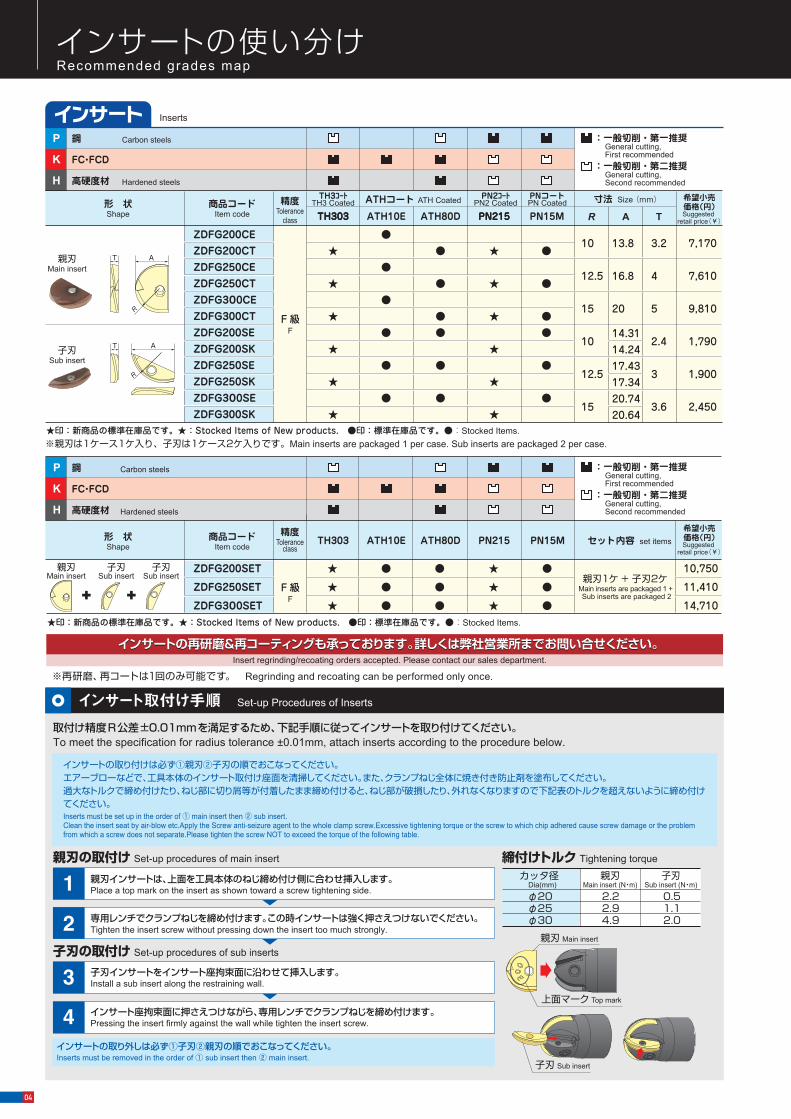
※親刃は1ケース1ケ入り、子刃は1ケース2ケ入りです。Main inserts are packaged 1 per case. Sub inserts are packaged 2 per case.
ZDFG200SET
ZDFG250SET
ZDFG300SET
10,750
11,410
14,710
商品コードItem code
精度Tolerance
class形 状Shape
セット内容 set items
親刃1ケ + 子刃2ケ Main inserts are packaged 1 + Sub inserts are packaged 2
F 級F
インサートの再研磨&再コーティングも承っております。詳しくは弊社営業所までお問い合せください。インサートの再研磨&再コーティングも承っております。詳しくは弊社営業所までお問い合せください。 Insert regrinding/recoating orders accepted. Please contact our sales department.
※再研磨、再コートは1回のみ可能です。 Regrinding and recoating can be performed only once.
:一般切削・第一推奨 General cutting, First recommended:一般切削・第二推奨 General cutting, Second recommended
:一般切削・第一推奨 General cutting, First recommended:一般切削・第二推奨 General cutting, Second recommended
鋼
FC・FCD
高硬度材
Carbon steels
Hardened steels
P
K
H
★
★
★
★
★
★
★
★
★
★
★
★
鋼
FC・FCD
高硬度材
Carbon steels
Hardened steels
P
K
H
親刃Main insert
子刃Sub insert
子刃Sub insert
希望小売価格(円)Suggested
retail price(¥)
希望小売価格(円)Suggested
retail price(¥)
★
★
★
取付け精度R公差±0.01mmを満足するため、下記手順に従ってインサートを取り付けてください。To meet the specification for radius tolerance ±0.01mm, attach inserts according to the procedure below.
インサートの取り付けは必ず①親刃②子刃の順でおこなってください。エアーブローなどで、工具本体のインサート取付け座面を清掃してください。また、クランプねじ全体に焼き付き防止剤を塗布してください。過大なトルクで締め付けたり、ねじ部に切り屑等が付着したまま締め付けると、ねじ部が破損したり、外れなくなりますので下記表のトルクを超えないように締め付けてください。Inserts must be set up in the order of ① main insert then ② sub insert.Clean the insert seat by air-blow etc.Apply the Screw anti-seizure agent to the whole clamp screw.Excessive tightening torque or the screw to which chip adhered cause screw damage or the problem from which a screw does not separate.Please tighten the screw NOT to exceed the torque of the following table.
インサートの取り外しは必ず①子刃②親刃の順でおこなってください。 Inserts must be removed in the order of ① sub insert then ② main insert.
親刃の取付け Set-up procedures of main insert
カッタ径 Dia(mm)
親刃Main insert (N・m)
子刃Sub insert (N・m)
φ20φ25φ30
2.22.94.9
0.51.12.0
締付けトルク Tightening torque
親刃インサートは、上面を工具本体のねじ締め付け側に合わせ挿入します。Place a top mark on the insert as shown toward a screw tightening side.1
インサート座拘束面に押さえつけながら、専用レンチでクランプねじを締め付けます。Pressing the insert firmly against the wall while tighten the insert screw.4
専用レンチでクランプねじを締め付けます。この時インサートは強く押さえつけないでください。Tighten the insert screw without pressing down the insert too much strongly.2
子刃インサートをインサート座拘束面に沿わせて挿入します。
子刃の取付け Set-up procedures of sub inserts
Install a sub insert along the restraining wall.3上面マーク Top mark
親刃 Main insert
子刃 Sub insert
Insertsインサート
★印:新商品の標準在庫品です。★:Stocked Items of New products. ●印:標準在庫品です。●:Stocked Items.
★印:新商品の標準在庫品です。★:Stocked Items of New products. ●印:標準在庫品です。●:Stocked Items.
インサート取付け手順 Set-up Procedures of Inserts
04
標準切削条件表 Recommended cut t ing condi t ions
インサートの使い分けRecommended grades map
ZDFG200CEZDFG200CTZDFG250CEZDFG250CTZDFG300CEZDFG300CTZDFG200SEZDFG200SKZDFG250SEZDFG250SKZDFG300SEZDFG300SK
7,170
7,610
9,810
1,790
1,900
2,450
商品コードItem code
精度Tolerance
class
形 状Shape
ATHコート ATH Coated PNコートPN Coated
PN2コートPN2 Coated
TH3コートTH3 Coated 寸法 Size (mm)
AR TATH10E ATH80D PN15MPN215TH303 PN215TH303
PN215TH303 ATH10E ATH80D PN15M
10
12.5
15
10
12.5
15
13.8
16.8
20
14.3114.2417.4317.3420.7420.64
3.2
4
5
2.4
3
3.6
F 級F
●
●
●
●
●
●
●
●
●●
●
●
●
●
●●
●
●
●
●
●
●
●
●
●
●
●
★
★
★
親刃Main insert
A
R
T
子刃Sub insert
AT
R
※親刃は1ケース1ケ入り、子刃は1ケース2ケ入りです。Main inserts are packaged 1 per case. Sub inserts are packaged 2 per case.
ZDFG200SET
ZDFG250SET
ZDFG300SET
10,750
11,410
14,710
商品コードItem code
精度Tolerance
class形 状Shape
セット内容 set items
親刃1ケ + 子刃2ケ Main inserts are packaged 1 + Sub inserts are packaged 2
F 級F
インサートの再研磨&再コーティングも承っております。詳しくは弊社営業所までお問い合せください。インサートの再研磨&再コーティングも承っております。詳しくは弊社営業所までお問い合せください。 Insert regrinding/recoating orders accepted. Please contact our sales department.
※再研磨、再コートは1回のみ可能です。 Regrinding and recoating can be performed only once.
:一般切削・第一推奨 General cutting, First recommended:一般切削・第二推奨 General cutting, Second recommended
:一般切削・第一推奨 General cutting, First recommended:一般切削・第二推奨 General cutting, Second recommended
鋼
FC・FCD
高硬度材
Carbon steels
Hardened steels
P
K
H
★
★
★
★
★
★
★
★
★
★
★
★
鋼
FC・FCD
高硬度材
Carbon steels
Hardened steels
P
K
H
親刃Main insert
子刃Sub insert
子刃Sub insert
希望小売価格(円)Suggested
retail price(¥)
希望小売価格(円)Suggested
retail price(¥)
★
★
★
取付け精度R公差±0.01mmを満足するため、下記手順に従ってインサートを取り付けてください。To meet the specification for radius tolerance ±0.01mm, attach inserts according to the procedure below.
インサートの取り付けは必ず①親刃②子刃の順でおこなってください。エアーブローなどで、工具本体のインサート取付け座面を清掃してください。また、クランプねじ全体に焼き付き防止剤を塗布してください。過大なトルクで締め付けたり、ねじ部に切り屑等が付着したまま締め付けると、ねじ部が破損したり、外れなくなりますので下記表のトルクを超えないように締め付けてください。Inserts must be set up in the order of ① main insert then ② sub insert.Clean the insert seat by air-blow etc.Apply the Screw anti-seizure agent to the whole clamp screw.Excessive tightening torque or the screw to which chip adhered cause screw damage or the problem from which a screw does not separate.Please tighten the screw NOT to exceed the torque of the following table.
インサートの取り外しは必ず①子刃②親刃の順でおこなってください。 Inserts must be removed in the order of ① sub insert then ② main insert.
親刃の取付け Set-up procedures of main insert
カッタ径 Dia(mm)
親刃Main insert (N・m)
子刃Sub insert (N・m)
φ20φ25φ30
2.22.94.9
0.51.12.0
締付けトルク Tightening torque
親刃インサートは、上面を工具本体のねじ締め付け側に合わせ挿入します。Place a top mark on the insert as shown toward a screw tightening side.1
インサート座拘束面に押さえつけながら、専用レンチでクランプねじを締め付けます。Pressing the insert firmly against the wall while tighten the insert screw.4
専用レンチでクランプねじを締め付けます。この時インサートは強く押さえつけないでください。Tighten the insert screw without pressing down the insert too much strongly.2
子刃インサートをインサート座拘束面に沿わせて挿入します。
子刃の取付け Set-up procedures of sub inserts
Install a sub insert along the restraining wall.3上面マーク Top mark
親刃 Main insert
子刃 Sub insert
Insertsインサート
★印:新商品の標準在庫品です。★:Stocked Items of New products. ●印:標準在庫品です。●:Stocked Items.
★印:新商品の標準在庫品です。★:Stocked Items of New products. ●印:標準在庫品です。●:Stocked Items.
インサート取付け手順 Set-up Procedures of Inserts
05
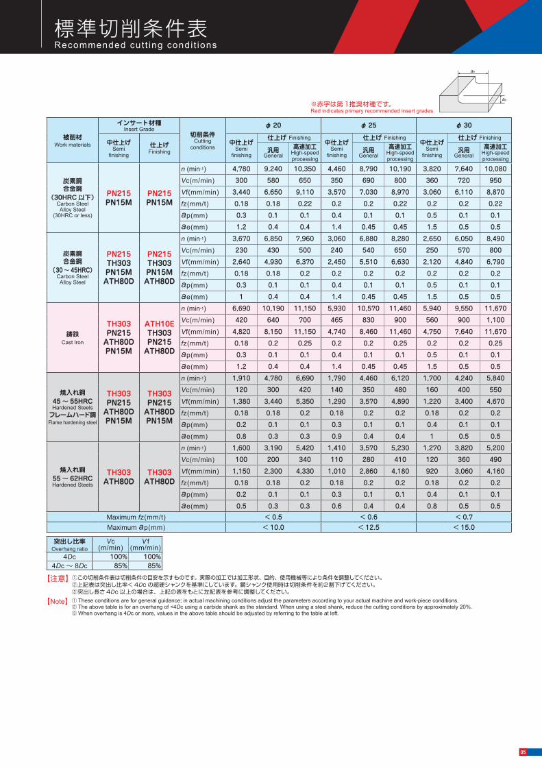
被削材Work materials
インサート材種Insert Grade
切削条件 Cutting
conditions
φ 20 φ 25 φ 30
中仕上げSemi
finishing
仕上げ Finishing
中仕上げSemi
finishing
仕上げ Finishing中仕上げ
Semi finishing
仕上げ Finishing中仕上げ
Semi finishing
仕上げ Finishing
汎用General
高速加工 High-speed processing
汎用General
高速加工 High-speed processing
汎用General
高速加工 High-speed processing
炭素鋼合金鋼
(30HRC 以下)Carbon SteelAlloy Steel
(30HRC or less)
PN215PN15M
PN215PN15M
n (min-1) 4,780 9,240 10,350 4,460 8,790 10,190 3,820 7,640 10,080
Vc(m/min) 300 580 650 350 690 800 360 720 950
Vf(mm/min) 3,440 6,650 9,110 3,570 7,030 8,970 3,060 6,110 8,870
fz(mm/t) 0.18 0.18 0.22 0.2 0.2 0.22 0.2 0.2 0.22
ap(mm) 0.3 0.1 0.1 0.4 0.1 0.1 0.5 0.1 0.1
ae(mm) 1.2 0.4 0.4 1.4 0.45 0.45 1.5 0.5 0.5
炭素鋼合金鋼
(30 〜 45HRC)Carbon SteelAlloy Steel
PN215TH303PN15MATH80D
PN215TH303PN15MATH80D
n (min-1) 3,670 6,850 7,960 3,060 6,880 8,280 2,650 6,050 8,490
Vc(m/min) 230 430 500 240 540 650 250 570 800
Vf(mm/min) 2,640 4,930 6,370 2,450 5,510 6,630 2,120 4,840 6,790
fz(mm/t) 0.18 0.18 0.2 0.2 0.2 0.2 0.2 0.2 0.2
ap(mm) 0.3 0.1 0.1 0.4 0.1 0.1 0.5 0.1 0.1
ae(mm) 1 0.4 0.4 1.4 0.45 0.45 1.5 0.5 0.5
鋳鉄Cast Iron
TH303PN215
ATH80DPN15M
ATH10ETH303PN215
ATH80D
n (min-1) 6,690 10,190 11,150 5,930 10,570 11,460 5,940 9,550 11,670
Vc(m/min) 420 640 700 465 830 900 560 900 1,100
Vf(mm/min) 4,820 8,150 11,150 4,740 8,460 11,460 4,750 7,640 11,670
fz(mm/t) 0.18 0.2 0.25 0.2 0.2 0.25 0.2 0.2 0.25
ap(mm) 0.3 0.1 0.1 0.4 0.1 0.1 0.5 0.1 0.1
ae(mm) 1.2 0.4 0.4 1.4 0.45 0.45 1.5 0.5 0.5
焼入れ鋼45 〜 55HRCHardened Steels
フレームハード鋼Flame hardening steel
TH303PN215
ATH80DPN15M
TH303PN215
ATH80DPN15M
n (min-1) 1,910 4,780 6,690 1,790 4,460 6,120 1,700 4,240 5,840
Vc(m/min) 120 300 420 140 350 480 160 400 550
Vf(mm/min) 1,380 3,440 5,350 1,290 3,570 4,890 1,220 3,400 4,670
fz(mm/t) 0.18 0.18 0.2 0.18 0.2 0.2 0.18 0.2 0.2
ap(mm) 0.2 0.1 0.1 0.3 0.1 0.1 0.4 0.1 0.1
ae(mm) 0.8 0.3 0.3 0.9 0.4 0.4 1 0.5 0.5
焼入れ鋼55 〜 62HRCHardened Steels
TH303ATH80D
TH303ATH80D
n (min-1) 1,600 3,190 5,420 1,410 3,570 5,230 1,270 3,820 5,200
Vc(m/min) 100 200 340 110 280 410 120 360 490
Vf(mm/min) 1,150 2,300 4,330 1,010 2,860 4,180 920 3,060 4,160
fz(mm/t) 0.18 0.18 0.2 0.18 0.2 0.2 0.18 0.2 0.2
ap(mm) 0.2 0.1 0.1 0.3 0.1 0.1 0.4 0.1 0.1
ae(mm) 0.5 0.3 0.3 0.6 0.4 0.4 0.8 0.5 0.5 Maximum fz(mm/t) < 0.5 < 0.6 < 0.7Maximum ap(mm) < 10.0 < 12.5 < 15.0
突出し比率 Overhang ratio
Vc(m/min)
V f(mm/min)
4Dc 100% 100%4Dc〜 8Dc 85% 85%
①この切削条件表は切削条件の目安を示すものです。実際の加工では加工形状、目的、使用機械等により条件を調整してください。②上記表は突出し比率<4Dc の超硬シャンクを基準にしています。鋼シャンク使用時は切削条件を約2割下げてください。③突出し長さ4Dc 以上の場合は、上記の表をもとに左記表を参考に調整してください。
※赤字は第1推奨材種です。Red indicates primary recommended insert grades.
【注意】
① These conditions are for general guidance; in actual machining conditions adjust the parameters according to your actual machine and work-piece conditions.② The above table is for an overhang of <4Dc using a carbide shank as the standard. When using a steel shank, reduce the cutting conditions by approximately 20%.③When overhang is 4Dc or more, values in the above table should be adjusted by referring to the table at left.
【Note】
ae
ap
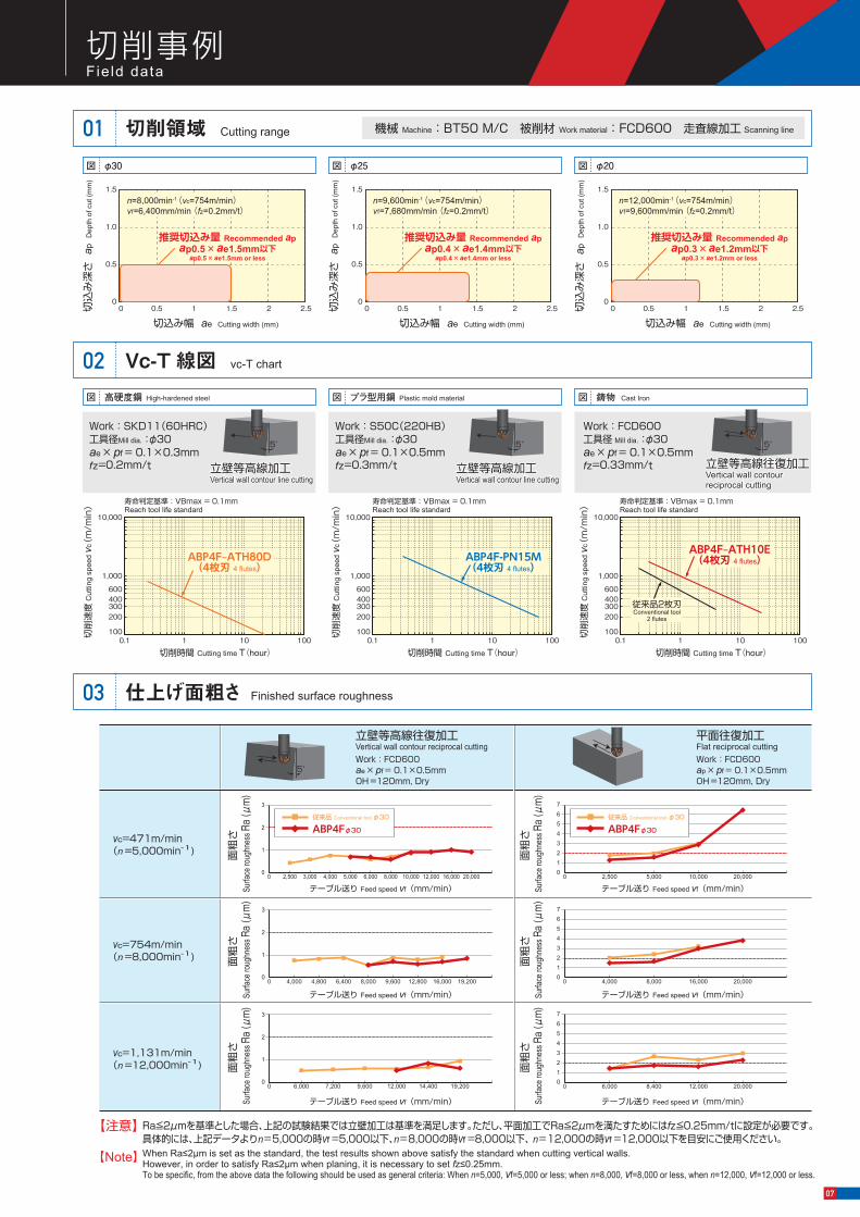
切削事例 Field data
図 φ30 図 φ25 図 φ20
図 高硬度鋼 High-hardened steel 図 プラ型用鋼 Plastic mold material 図 鋳物 Cast Iron
切削性能 Cutt ing performance
中仕上げ加工面の比較(FCD600)01 切削領域01Compared with cutting surface after semi-finishing (FCD600) Cutting range
Vc-T 線図02 vc-T chart
仕上げ面粗さ03 Finished surface roughness
平面加工における能率比較02Performance comparison when cutting flat surfaces
立壁加工における寿命比較03Tool life comparison when cutting vertical walls
曲面加工の摩耗比較04 Wear comparison when profiling
切削
速度
Cut
ting
spee
d vc
(m
/min
)
切削時間 Cutting time T(hour)
100
200300400600
1,000
10,000
0.1 1 10 100
寿命判定基準:VBmax = 0.1mmReach tool life standard
切削
速度
Cut
ting
spee
d vc
(m
/min
)
切削時間 Cutting time T(hour)
100
200300400600
1,000
10,000
0.1 1 10 100
寿命判定基準:VBmax = 0.1mmReach tool life standard
切削
速度
Cut
ting
spee
d vc
(m
/min
)
切削時間 Cutting time T(hour)
100
200300400600
1,000
10,000
0.1 1 10 100
寿命判定基準:VBmax = 0.1mmReach tool life standard
切削条件 Cutting conditions
被削材 Work material:FCD600工具径 Mill dia.:φ30 ATH10E OH =150mmvc=1,130m/min
(n =12,000min-1) ap × pf = 0.1×0.5mmDry 切削長 Cutting length L=10km
切削条件 Cutting conditions
被削材 Work material:FCD600工具径 Mill dia.:φ30 ATH10E OH =150mmvc=1,130m/min
(n =12,000min-1)ae × pf = 0.1×0.5mmfz=0.33mm/t Dry
機械 Machine:BT50 M/C 被削材 Work material:FCD600 走査線加工 Scanning line
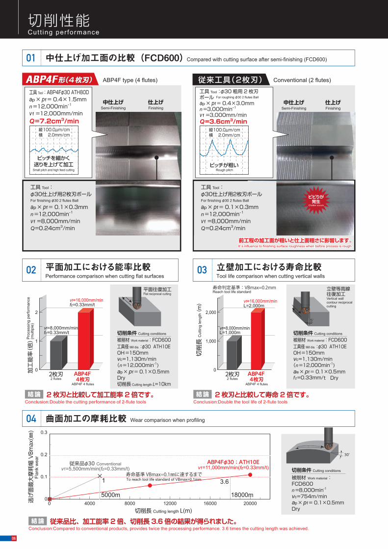
2枚刃と比較して加工能率2倍です。2 枚刃と比較して加工能率 2 倍です。結論Conclusion:Double the cutting performance of 2-flute tools
2 枚刃と比較して寿命 2 倍です。2 枚刃と比較して寿命 2 倍です。結論Conclusion:Double the tool life of 2-flute tools
切削条件 Cutting conditions
被削材 Work material:FCD600 n =8,000min-1 vc=754m/min ap × pf = 0.1×0.5mm Dry
平面往復加工Flat reciprocal cutting
5°
立壁等高線往復加工Vertical wall contour reciprocal cutting
切削
長C
uttin
g le
ngth(
m)
2枚刃2 flutes
ABP4F4枚刃
ABP4F 4 flutes
0
1,000
2,000
vf=16,000mm/minL=2,000m
vf=8,000mm/minL=1,000m
寿命判定基準:VBmax=0.2mmReach tool life standard
加工
能率(
倍)
2枚刃2 flutes
ABP4F4枚刃
ABP4F 4 flutes
0
1
2
vf=16,000mm/minfz=0.33mm/t
vf=8,000mm/minfz=0.33mm/t
Pro
cess
ing
perfo
rman
ce(m
ultip
le)
0 1234567
0 2,500 5,000 10,000 20,000
vc=471m/min(n =5,000min-1)
vc=754m/min(n =8,000min-1)
vc=1,131m/min(n =12,000min-1)
0 1234567
0 4,000 8,000 16,000 20,000
Work:FCD600ap × pf = 0.1×0.5mmOH =120mm, Dry
Work:FCD600ae × pf = 0.1×0.5mmOH =120mm, Dry
0 1234567
0 6,000 8,400 12,000 20,000
0
1
2
3
0 2,500 3,000 4,000 5,000 6,000 8,000 10,000 12,000 16,000 20,000
面粗
さ S
urfac
e rou
ghne
ss R
a (μ
m)
テーブル送り Feed speed vf (mm/min)
面粗
さ S
urfac
e rou
ghne
ss R
a (μ
m)
テーブル送り Feed speed vf (mm/min)
面粗
さ S
urfac
e rou
ghne
ss R
a (μ
m)
テーブル送り Feed speed vf (mm/min)
面粗
さ S
urfac
e rou
ghne
ss R
a (μ
m)
テーブル送り Feed speed vf (mm/min)
面粗
さ S
urfac
e rou
ghne
ss R
a (μ
m)
テーブル送り Feed speed vf (mm/min)
面粗
さ S
urfac
e rou
ghne
ss R
a (μ
m)
テーブル送り Feed speed vf (mm/min)
0
1
2
3
0 4,000 4,800 6,400 8,000 9,600 12,800 16,000 19,200
0
1
2
3
0 6,000 7,200 9,600 12,000 14,400 19,200
【注意】
【Note】
Ra≦2μmを基準とした場合、上記の試験結果では立壁加工は基準を満足します。ただし、平面加工でRa≦2μmを満たすためにはfz≦0.25mm/tに設定が必要です。具体的には、上記データよりn=5,000の時vf =5,000以下、n=8,000の時vf =8,000以下、 n=12,000の時vf =12,000以下を目安にご使用ください。When Ra≤2µm is set as the standard, the test results shown above satisfy the standard when cutting vertical walls. However, in order to satisfy Ra≤2µm when planing, it is necessary to set fz≤0.25mm. To be specific, from the above data the following should be used as general criteria: When n=5,000, vf=5,000 or less; when n=8,000, vf=8,000 or less, when n=12,000, vf=12,000 or less.
立壁等高線往復加工Vertical wall contour reciprocal cutting
5°
平面往復加工Flat reciprocal cutting
ABP4Fφ30
従来品 Conventional tool φ30
ABP4Fφ30
従来品 Conventional tool φ30
Work:FCD600 工具径 Mill dia.:φ30 ae × pf = 0.1×0.5mm fz=0.33mm/t
従来品2枚刃Conventional tool
2 flutes
ABP4F‒ATH10E(4枚刃 4 flutes)
立壁等高線往復加工Vertical wall contour reciprocal cutting
5°
Work:SKD11(60HRC) 工具径Mill dia.:φ30 ae × pf = 0.1×0.3mm fz=0.2mm/t 立壁等高線加工
Vertical wall contour line cutting
5°
ABP4F type (4 flutes) 従来工具(2枚刃) Conventional (2 flutes)
工具 Tool:ABP4Fφ30 ATH80Dap × pf = 0.4×1.5mmn =12,000min-1
v f =12,000mm/minQ=7.2cm3/min
中仕上げSemi-Finishing
仕上げFinishing
縦 100.0μm/cm横 2.0mm/cm
工具 Tool:φ30仕上げ用2枚刃ボールFor finishing φ30 2 flutes Ball
ap × pf = 0.1×0.3mmn =12,000min-1
v f =8,000mm/minQ=0.24cm3/min
工具 Tool:φ30 粗用 2 枚刃ボールap × pf = 0.4×3.0mmn =3,000min-1
v f =3,000mm/minQ=3.6cm3/min
中仕上げSemi-Finishing
仕上げFinishing
工具 Tool:φ30仕上げ用2枚刃ボールFor finishing φ30 2 flutes Ball
ap × pf = 0.1×0.3mmn =12,000min-1
v f =8,000mm/minQ=0.24cm3/min
For roughing φ30 2 flutes Ball
Small pitch and high feed cutting
縦 100.0μm/cm横 2.0mm/cm
ピッチを細かく送りを上げて加工 ピッチが粗い
ビビりが発生
Chatter occurs
前工程の加工面が粗いと仕上面粗さに影響します。It’ s influence to finishing surface roughness when before process is rough.前工程の加工面が粗いと仕上面粗さに影響します。It’ s influence to finishing surface roughness when before process is rough.
ABP4F‒ATH80D(4枚刃 4 flutes)
Work:S50C(220HB) 工具径Mill dia.:φ30 ae × pf = 0.1×0.5mm fz=0.3mm/t 立壁等高線加工
Vertical wall contour line cutting
5°
ABP4F-PN15M(4枚刃 4 flutes)
Rough pitch
従来品比、加工能率 2 倍、切削長 3.6 倍の結果が得られました。従来品比、加工能率 2 倍、切削長 3.6 倍の結果が得られました。結論Conclusion:Compared to conventional products, provides twice the processing performance. 3.6 times the cutting length was achieved.
逃げ
面最
大摩
耗幅
VBm
ax(㎜
)Fl
ank
wea
r
切削長 Cutting length L(m)
0
0.1
0.2
0.3
4000 8000 12000 16000 200000
1 3.6
18000m5000m
従来品φ30 Conventionalv f=5,500mm/min(fz=0.33mm/t)
ABP4Fφ30:ATH10Ev f=11,000mm/min(fz=0.33mm/t)
ABP4Fφ30:ATH10Ev f=11,000mm/min(fz=0.33mm/t)
寿命基準 VBmax=0.1㎜に達するまでTo reach tool life standard of VBmax=0.1mm
30°
1.5
1.0
0.5
00 0.5 1 1.5 2 2.5
切込み幅 ae Cutting width (mm)
推奨切込み量 Recommended apap0.5 × ae1.5mm以下
ap0.5 × ae1.5mm or less
切込
み深
さ a
p D
epth
of c
ut (m
m)
n=8,000min-1 (vc=754m/min)vf=6,400mm/min (fz=0.2mm/t)
1.5
1.0
0.5
00 0.5 1 1.5 2 2.5
切込み幅 ae Cutting width (mm)
推奨切込み量 Recommended apap0.4 × ae1.4mm以下
ap0.4 × ae1.4mm or less
切込
み深
さ a
p D
epth
of c
ut (m
m)
n=9,600min-1 (vc=754m/min)vf=7,680mm/min (fz=0.2mm/t)
1.5
1.0
0.5
00 0.5 1 1.5 2 2.5
切込み幅 ae Cutting width (mm)
推奨切込み量 Recommended apap0.3 × ae1.2mm以下
ap0.3 × ae1.2mm or less
切込
み深
さ a
p D
epth
of c
ut (m
m)
n=12,000min-1 (vc=754m/min)vf=9,600mm/min (fz=0.2mm/t)
06
切削事例 Field data
図 φ30 図 φ25 図 φ20
図 高硬度鋼 High-hardened steel 図 プラ型用鋼 Plastic mold material 図 鋳物 Cast Iron
切削性能 Cutt ing performance
中仕上げ加工面の比較(FCD600)01 切削領域01Compared with cutting surface after semi-finishing (FCD600) Cutting range
Vc-T 線図02 vc-T chart
仕上げ面粗さ03 Finished surface roughness
平面加工における能率比較02Performance comparison when cutting flat surfaces
立壁加工における寿命比較03Tool life comparison when cutting vertical walls
曲面加工の摩耗比較04 Wear comparison when profiling
切削
速度
Cut
ting
spee
d vc
(m
/min
)
切削時間 Cutting time T(hour)
100
200300400600
1,000
10,000
0.1 1 10 100
寿命判定基準:VBmax = 0.1mmReach tool life standard
切削
速度
Cut
ting
spee
d vc
(m
/min
)
切削時間 Cutting time T(hour)
100
200300400600
1,000
10,000
0.1 1 10 100
寿命判定基準:VBmax = 0.1mmReach tool life standard
切削
速度
Cut
ting
spee
d vc
(m
/min
)
切削時間 Cutting time T(hour)
100
200300400600
1,000
10,000
0.1 1 10 100
寿命判定基準:VBmax = 0.1mmReach tool life standard
切削条件 Cutting conditions
被削材 Work material:FCD600工具径 Mill dia.:φ30 ATH10E OH =150mmvc=1,130m/min
(n =12,000min-1) ap × pf = 0.1×0.5mmDry 切削長 Cutting length L=10km
切削条件 Cutting conditions
被削材 Work material:FCD600工具径 Mill dia.:φ30 ATH10E OH =150mmvc=1,130m/min
(n =12,000min-1)ae × pf = 0.1×0.5mmfz=0.33mm/t Dry
機械 Machine:BT50 M/C 被削材 Work material:FCD600 走査線加工 Scanning line
2枚刃と比較して加工能率2倍です。2 枚刃と比較して加工能率 2 倍です。結論Conclusion:Double the cutting performance of 2-flute tools
2 枚刃と比較して寿命 2 倍です。2 枚刃と比較して寿命 2 倍です。結論Conclusion:Double the tool life of 2-flute tools
切削条件 Cutting conditions
被削材 Work material:FCD600 n =8,000min-1 vc=754m/min ap × pf = 0.1×0.5mm Dry
平面往復加工Flat reciprocal cutting
5°
立壁等高線往復加工Vertical wall contour reciprocal cutting
切削
長C
uttin
g le
ngth(
m)
2枚刃2 flutes
ABP4F4枚刃
ABP4F 4 flutes
0
1,000
2,000
vf=16,000mm/minL=2,000m
vf=8,000mm/minL=1,000m
寿命判定基準:VBmax=0.2mmReach tool life standard
加工
能率(
倍)
2枚刃2 flutes
ABP4F4枚刃
ABP4F 4 flutes
0
1
2
vf=16,000mm/minfz=0.33mm/t
vf=8,000mm/minfz=0.33mm/t
Pro
cess
ing
perfo
rman
ce(m
ultip
le)
0 1234567
0 2,500 5,000 10,000 20,000
vc=471m/min(n =5,000min-1)
vc=754m/min(n =8,000min-1)
vc=1,131m/min(n =12,000min-1)
0 1234567
0 4,000 8,000 16,000 20,000
Work:FCD600ap × pf = 0.1×0.5mmOH =120mm, Dry
Work:FCD600ae × pf = 0.1×0.5mmOH =120mm, Dry
0 1234567
0 6,000 8,400 12,000 20,000
0
1
2
3
0 2,500 3,000 4,000 5,000 6,000 8,000 10,000 12,000 16,000 20,000
面粗
さ S
urfac
e rou
ghne
ss R
a (μ
m)
テーブル送り Feed speed vf (mm/min)
面粗
さ S
urfac
e rou
ghne
ss R
a (μ
m)
テーブル送り Feed speed vf (mm/min)
面粗
さ S
urfac
e rou
ghne
ss R
a (μ
m)
テーブル送り Feed speed vf (mm/min)
面粗
さ S
urfac
e rou
ghne
ss R
a (μ
m)
テーブル送り Feed speed vf (mm/min)
面粗
さ S
urfac
e rou
ghne
ss R
a (μ
m)
テーブル送り Feed speed vf (mm/min)
面粗
さ S
urfac
e rou
ghne
ss R
a (μ
m)
テーブル送り Feed speed vf (mm/min)
0
1
2
3
0 4,000 4,800 6,400 8,000 9,600 12,800 16,000 19,200
0
1
2
3
0 6,000 7,200 9,600 12,000 14,400 19,200
【注意】
【Note】
Ra≦2μmを基準とした場合、上記の試験結果では立壁加工は基準を満足します。ただし、平面加工でRa≦2μmを満たすためにはfz≦0.25mm/tに設定が必要です。具体的には、上記データよりn=5,000の時vf =5,000以下、n=8,000の時vf =8,000以下、 n=12,000の時vf =12,000以下を目安にご使用ください。When Ra≤2µm is set as the standard, the test results shown above satisfy the standard when cutting vertical walls. However, in order to satisfy Ra≤2µm when planing, it is necessary to set fz≤0.25mm. To be specific, from the above data the following should be used as general criteria: When n=5,000, vf=5,000 or less; when n=8,000, vf=8,000 or less, when n=12,000, vf=12,000 or less.
立壁等高線往復加工Vertical wall contour reciprocal cutting
5°
平面往復加工Flat reciprocal cutting
ABP4Fφ30
従来品 Conventional tool φ30
ABP4Fφ30
従来品 Conventional tool φ30
Work:FCD600 工具径 Mill dia.:φ30 ae × pf = 0.1×0.5mm fz=0.33mm/t
従来品2枚刃Conventional tool
2 flutes
ABP4F‒ATH10E(4枚刃 4 flutes)
立壁等高線往復加工Vertical wall contour reciprocal cutting
5°
Work:SKD11(60HRC) 工具径Mill dia.:φ30 ae × pf = 0.1×0.3mm fz=0.2mm/t 立壁等高線加工
Vertical wall contour line cutting
5°
ABP4F type (4 flutes) 従来工具(2枚刃) Conventional (2 flutes)
工具 Tool:ABP4Fφ30 ATH80Dap × pf = 0.4×1.5mmn =12,000min-1
v f =12,000mm/minQ=7.2cm3/min
中仕上げSemi-Finishing
仕上げFinishing
縦 100.0μm/cm横 2.0mm/cm
工具 Tool:φ30仕上げ用2枚刃ボールFor finishing φ30 2 flutes Ball
ap × pf = 0.1×0.3mmn =12,000min-1
v f =8,000mm/minQ=0.24cm3/min
工具 Tool:φ30 粗用 2 枚刃ボールap × pf = 0.4×3.0mmn =3,000min-1
v f =3,000mm/minQ=3.6cm3/min
中仕上げSemi-Finishing
仕上げFinishing
工具 Tool:φ30仕上げ用2枚刃ボールFor finishing φ30 2 flutes Ball
ap × pf = 0.1×0.3mmn =12,000min-1
v f =8,000mm/minQ=0.24cm3/min
For roughing φ30 2 flutes Ball
Small pitch and high feed cutting
縦 100.0μm/cm横 2.0mm/cm
ピッチを細かく送りを上げて加工 ピッチが粗い
ビビりが発生
Chatter occurs
前工程の加工面が粗いと仕上面粗さに影響します。It’ s influence to finishing surface roughness when before process is rough.前工程の加工面が粗いと仕上面粗さに影響します。It’ s influence to finishing surface roughness when before process is rough.
ABP4F‒ATH80D(4枚刃 4 flutes)
Work:S50C(220HB) 工具径Mill dia.:φ30 ae × pf = 0.1×0.5mm fz=0.3mm/t 立壁等高線加工
Vertical wall contour line cutting
5°
ABP4F-PN15M(4枚刃 4 flutes)
Rough pitch
従来品比、加工能率 2 倍、切削長 3.6 倍の結果が得られました。従来品比、加工能率 2 倍、切削長 3.6 倍の結果が得られました。結論Conclusion:Compared to conventional products, provides twice the processing performance. 3.6 times the cutting length was achieved.
逃げ
面最
大摩
耗幅
VBm
ax(㎜
)Fl
ank
wea
r
切削長 Cutting length L(m)
0
0.1
0.2
0.3
4000 8000 12000 16000 200000
1 3.6
18000m5000m
従来品φ30 Conventionalv f=5,500mm/min(fz=0.33mm/t)
ABP4Fφ30:ATH10Ev f=11,000mm/min(fz=0.33mm/t)
ABP4Fφ30:ATH10Ev f=11,000mm/min(fz=0.33mm/t)
寿命基準 VBmax=0.1㎜に達するまでTo reach tool life standard of VBmax=0.1mm
30°
1.5
1.0
0.5
00 0.5 1 1.5 2 2.5
切込み幅 ae Cutting width (mm)
推奨切込み量 Recommended apap0.5 × ae1.5mm以下
ap0.5 × ae1.5mm or less
切込
み深
さ a
p D
epth
of c
ut (m
m)
n=8,000min-1 (vc=754m/min)vf=6,400mm/min (fz=0.2mm/t)
1.5
1.0
0.5
00 0.5 1 1.5 2 2.5
切込み幅 ae Cutting width (mm)
推奨切込み量 Recommended apap0.4 × ae1.4mm以下
ap0.4 × ae1.4mm or less
切込
み深
さ a
p D
epth
of c
ut (m
m)
n=9,600min-1 (vc=754m/min)vf=7,680mm/min (fz=0.2mm/t)
1.5
1.0
0.5
00 0.5 1 1.5 2 2.5
切込み幅 ae Cutting width (mm)
推奨切込み量 Recommended apap0.3 × ae1.2mm以下
ap0.3 × ae1.2mm or less
切込
み深
さ a
p D
epth
of c
ut (m
m)
n=12,000min-1 (vc=754m/min)vf=9,600mm/min (fz=0.2mm/t)
07
図、表等のデータは試験結果の一例であり、保証値ではありません。「Epoch」「 」「 」は日本における三菱日立ツール株式会社の登録商標です。The diagrams and table data are examples of test results, and are not guaranteed values."Epoch" , “ ” and “ ” are registered trademarks of Mitsubishi Hitachi Tool Engineering, Ltd. in Japan.
ホームページ
工具選定データベース 【TOOL SEARCH】
フリーダイヤル技術相談http://www.mmc-hitachitool.co.jp
本社 〒130-0026 東京都墨田区両国4-31-11(ヒューリック両国ビル8階)03-6890-5101
+81-3-6890-5103FAX 03-6890-5134FAX +81-3-6890-5128International Sales Dept .:
安 全 上 の ご 注 意 Attentions on Safety
営業企画部 ☎03-6890-5102 FAX03-6890-5134 海外営業部 ☎03-6890-5103 FAX03-6890-5128
Printed in JAPANベジタブルインクで印刷しています。Printed using vegetable oil ink.
掲載価格は消費税抜きの単価を表示しております。予告なく、改良・改善のために仕様変更することがあります。Specifications for the products listed in this catalog are subject to change without notice due to replacement or modification.
☎☎☎☎☎☎
東京営業所東北営業所新潟営業所東関東営業所長野営業所北関東営業所神奈川営業所
名古屋営業所大阪営業所松江営業所中四営業所九州営業所北九州営業所
☎☎☎☎☎☎☎
052-687-915006-7668-01900852-40-0300082-536-2001092-289-7010093-434-2640
FAX052-687-9144FAX06-7668-0194FAX0852-40-0617FAX082-536-2003FAX092-289-7012FAX093-434-6846
03-6890-5110022-208-51000258-29-30390294-88-94300268-21-37000276-59-6001046-400-9429
FAX03-6890-5133FAX022-208-5102FAX0258-29-3092FAX0294-88-9432FAX0268-21-3711FAX0276-59-6005FAX046-400-9435
ヨーロッパ/MMC Hitachi Tool Engineering Europe GmbH Itterpark 12, 40724 Hilden, Germany. TEL : +49-(0)2103-24820, FAX : +49-(0)2103-248230中 国/菱材日立刀具(上海)有限公司 郵編200003中国上海市黄浦区南京西路288号(創興金融中心1101室) TEL:+86-(0)21-3366-3058, FAX:+86-(0)21-3366-3050アメリカ/MITSUBISHI MATERIALS U.S.A. CORPORATION 41700 Gardenbrook Road, Suite 120, Novi, MI 48375-1320 U.S.A. TEL : +1(248)308-2620, FAX :+1(248)308-2627タ イ/MMC Hardmetal(Thailand)Co.,Ltd. HT-Division 399 Interchange 21 Building, 20th Floor, Unit no. 2015, Sukhumvit 21 Asoke Road, Klongtoey Nua, Wattana, Bangkok 10110, Thailand TEL: +66-(0)2-611-2520, FAX:+66-(0)2-611-2521イ ン ド/Hitachi Metals (India) Pvt. Ltd. Plot No 94 & 95,Sector 8, IMT Manesar, Gurgaon -122050, Haryana, India TEL : +91-124-4812315, FAX :+91-124-2290015
1. 取扱上のご注意(1)工具をケース(梱包)から取り出す際は、足元への落下あるいは素手の指先へ落して怪我をしないよう
に十分なご注意をお願いします。(2)インサートをセットして実際にご使用する場合は、切れ刃を素手で直接触れないように注意してください。
2. 取付け時のご注意(1)ご使用にあたって、インサートのセッティングは確実に行っていただき、アーバ等への取付けも確実に
行ってください。(2)ご使用中に、異常な振動等が発生した場合は、直ちに機械を停止させて、その振動の原因を除いてく
ださい。3. 使用上のご注意(1)切削工具あるいは被削材の寸法・回転の方向は、あらかじめ確認しておいてください。(2)標準切削条件表の数値は、新しい作業の立上げの目安としてご利用ください。切込みが大きい場合、
使用機械の剛性が小さい場合あるいは被加工物の性状に応じて切削条件を適正に調整してご使用ください。
(3)インサートは硬質の材料です。ご使用中に破損して飛散する場合があります。また、切りくずが飛散することがあります。これらの飛散物等は作業者を切傷させ、火傷あるいは目に入って負傷させる恐れがありますので、工具をご使用中はその周囲に安全カバーを取付け、保護めがね等の保護具を着用して安全な環境下での作業をお願いいたします。・引火や爆発の危険のあるところでは使用しないでください。・不水溶性切削油は、火災の恐れがありますので使用しないでください。
(4)工具を本来の目的以外に使用したり、改造したりしないでください。4. 超硬シャンクろう付けタイプエンドミル使用上のご注意
今回お買い上げ頂きました超硬合金シャンクろう付けタイプエンドミルは、鋼と超硬をろう付けで接合しているため、ろう接部の金属疲労により破損する危険性があります。よって、機械には十分に防護できる遮断板やガードを装着してご使用ください。更に超硬シャンクに改造を加えたり、強い衝撃を与えたり、又表面に傷やクラックが発生した場合は、使用を中止してください。
5. 再研削時のご注意(1)再研削時期が不適当であると工具が破損する恐れがあります。適正な工具と交換するか、再研削を
行ってください。(2)工具を再研削しますと粉塵が発生します。再研削時にはその周囲に安全カバーを取付け、保護め
がね等の保護具を着用してください。(3)本製品には特定化学物質に指定された コバルト及びその無機化合物が含まれています。再研削等
の加工を加える場合は特定化学物質障害予防規則(特化則)に従った取扱いをしてください。6. 工具に関して、安全上の問題点・不明の点・その他ご相談がありましたら フリーダイヤル技術相談 へ
お問い合わせください。
1. Attentions regarding handling(1) When removing the tool from the case (package), be careful not to drop it on your foot or drop
it onto the tips of your bare fingers.(2) When actually setting the inserts, be careful not to touch the cutting flute directly with your
bare hands.
2. Attentions regarding mounting(1) When preparing for use, be sure that the inserts are firmly mounted in place and that they are
firmly mounted on the arbor, etc.(2) If abnormal chattering occurs during use, stop the machine immediately and remove the
cause of the chattering.
3. Attentions during use(1) Before use, confirm the dimensions and direction of rotation of the tool and milling work material.(2) The numerical values in the standard cutting conditions table should be used as criteria when
starting new work. The cutting conditions should be adjusted as appropriate when the cutting depth is large, the rigidity of the machine being used is low, or according to the conditions of the work material.
(3) The inserts are made of a hard material. During use, they may break and fly off. In addition, cutting chips may also fly off. Since there is a danger of injury to workers, fire, or eye damage from such flying pieces, a safety cover should be installed and safety equipment such as safety glasses should be worn to create a safe environment for work.・Do not use where there is a risk of fire or explosion. ・Do not use non-water-soluble cutting oils. Such oils may result in fire.
(4) Do not use the tool for any purpose other than that for which it is intended, and do not modify it.
4. Attention on use of Carbide brazed end millCarbide brazed tools are made by brazing of carbide and steel.They may occurred breakage due to fatigue in brazing part.Therefore,it is strongly suggest to set board or guard to shut off shattering around the machines for the safety.Don't use in the case of remodeling carbide shank, giving strong impacts and occurring flaw and crack on the surface.
5. Attentions regarding regrinding(1) If regrinding is not performed at the proper time, there is a risk of the tool breaking. Replace the tool
with one in good condition, or perform regrinding.(2) Grinding dust will be created when regrinding a tool. When regrinding, be sure to attach a safety cover
over the work area and wear safety clothes such as safety goggles, etc.(3) This product contains the specified chemical substance cobalt and its inorganic compounds. When
performing regrinding or similar processing, be sure to handle the processing in accordance with thelocal laws and regulations regarding prevention of hazards due to specified chemical substances.
2017-9(ME-HNT3)2013-6:FP


![ÐÇå»ñïáÝdzÛÇ µ³ñÓñ éÇëÏÇ ÑÇí³Ý¹Ý»ñÇ ... · 2016-10-13 · ÓÄÊ 616.12-008.331.1]-085.224.036.8 . ÐÇå»ñïáÝdzÛÇ µ³ñÓñ éÇëÏÇ ÑÇí³Ý¹Ý»ñÇ](https://static.fdocument.pub/doc/165x107/5e6ab3b383e8ee5fc478af72/-2016-10-13.jpg)