AURA 2 0 Programming Installation
64
AURA 2.0 Emergency Response System Programming & Installation Manual REV. 1.0 - October 2010
-
Upload
roy-catron -
Category
Documents
-
view
223 -
download
1
description
Emergency Response System Programming & Installation Manual REV. 1.0 - October 2010 2 Ultimate Communicator Server 1.08 Figure 1 3 Aura 2 Server For a wireless device, press the reset button on the device to activate it Figure 9 4
Transcript of AURA 2 0 Programming Installation

AURA 2.0
Emergency Response System
Programming & Installation Manual
REV. 1.0 - October 2010

2
MODULES
1. Ultimate Communicator Server 1.08…………………………………………..…..Page 3
2. Aura 2 Server…………………………………………………………………………Pages 4 to 33
3. Spark……………………………………………………………………………………Pages 34 to 37
4. IMAGE LINK\Setup Prg Alerts................................................Pages 38 to 44
5. A2 Wireless – Ultimate Communicator App Link 1.35……………..……Page 45
6. Pager – Ultimate Communicator App Link 1.35………………………….…Page 46
7. A2 PI-1 Ultimate Communicator App Link 1.35…………………………..…Page 47
8. LightControl - Ultimate Communicator App Link 1.36………………..…Page 48
9. CG Client 1 – Ultimate Communicator ImageLink 1.03…….…Pages 49 to 55
10. Ultimate Call Accounting…………………………………………………….Pages 56 to 64

3
Ultimate Communicator Server 1.08 Used to connect all modules
Also called Router
1. Enter Maintenance Mode
Select Security --> Maintenance Level and the Security window will pop-up
Enter Password (Default password is Aura) and select OK.
2. Check
Check all the little windows on the Ultimate Communicator Server 1.08 to make sure all
the modules are running. (See Figure 1)
If a module or modules are not running it will not show on the Ultimate Communicator
Server 1.08.
Figure 1
4
Aura 2 Server This is the main module that processes overall everything for the Aura 2.0 system Runs all the processes in the background with user input 1. Enter Maintenance Mode
Select Security --> Maintenance Level and the Security window will pop-up
Enter Password (Default password is Aura) and select OK.
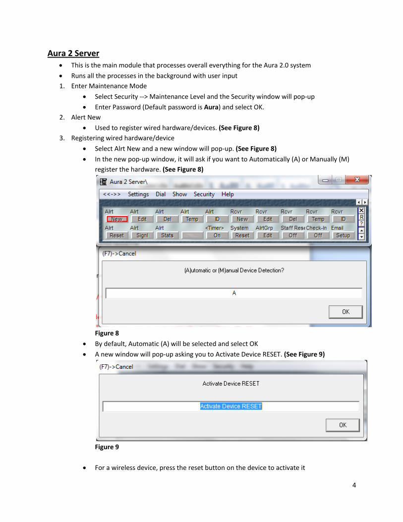
2. Alert New
Used to register wired hardware/devices. (See Figure 8)
3. Registering wired hardware/device
Select Alrt New and a new window will pop-up. (See Figure 8)
In the new pop-up window, it will ask if you want to Automatically (A) or Manually (M)
register the hardware. (See Figure 8)
Figure 8
By default, Automatic (A) will be selected and select OK
A new window will pop-up asking you to Activate Device RESET. (See Figure 9)
Figure 9
For a wireless device, press the reset button on the device to activate it

5
For a hardwired device, you need to go to the IMAGE LINK\Setup Prg Alerts module and
select Prg
The Input window will pop-up asking Registration for Scope (S), PLC (P), Ext (E).
(See Figure 10)
By default, PLC (P) is selected. (See Figure 10)
Enter the Registration and select OK. (See Figure 10)
Figure 10
Another Input window will pop-up asking for the Starting port number. (See Figure 11)
Enter the Starting port number and select OK. (See Figure 11)
Figure 11
Another Input window will pop-up asking for the Ending port number. (See Figure 12)
Enter the Ending port number and select OK. (See Figure 12)
Figure 12

6
The Wired Alert Ports window will pop-up showing the port numbers. (See Figure 13)
By default, Exit is selected and select OK to close Wired Alert Ports window.
(See Figure 13)
*NOTE: Scope will have A, B, C, D and PLC will have 1, 2, 3, 4 with the port numbers.
(See Figure 13 and 14)
A=1 --> Fast flash
B=2--> Slow flash
C=3--> Stead flash
D=4--> Reset
Figure 13 - PLC
Figure 14 – Scope
7
Jump to the Aura 2 Server module and select Alrt New and a new window will pop-up.
In the new pop-up window, it will ask if you want to Automatically (A) or Manually (M)
register the hardware. (See Figure 8)
By default, Automatic (A) will be selected and select OK. (See Figure 8)
A new window will pop-up asking you to Activate Device RESET. (See Figure 9)
Jump back to the IMAGE LINK\Setup Prg Alerts module and select the line with the
same port number and correct flash of the hardwired device
After selecting the correct line, you will see the words Activation Has Been Sent and
your template you have selected will pop-up.
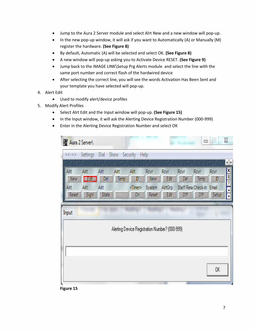
4. Alert Edit
Used to modify alert/device profiles
5. Modify Alert Profiles
Select Alrt Edit and the Input window will pop-up. (See Figure 15)
In the Input window, it will ask the Alerting Device Registration Number (000-999)
Enter in the Alerting Device Registration Number and select OK
Figure 15

8
The Alert Device Profile window will pop-up. (See Figure 16)
Figure 16
By default, Save Setting and Exit will be selected
All lines below Cancel Changes and Exit in the Alert Device Profile can be modified.
(See Figure 16)
To modify, select lines that needs to be modify and a pop-up window will allow you to
modify it
After modification is done, you have to select Save Settings and Exit to save, otherwise
select Cancel Changes and Exit to un-do modifications and exit without saving.
(See Figure 16)

9
6. Alert Delete
Used to delete alert/device profiles
7. Deleting Alert Profiles
Select Alrt Del and the Input window will pop-up. (See Figure 17)
In the Input window, it will ask the Alerting Device Registration Number (000-999)
Enter in the Alerting Device Registration Number and select OK
Figure 17
10
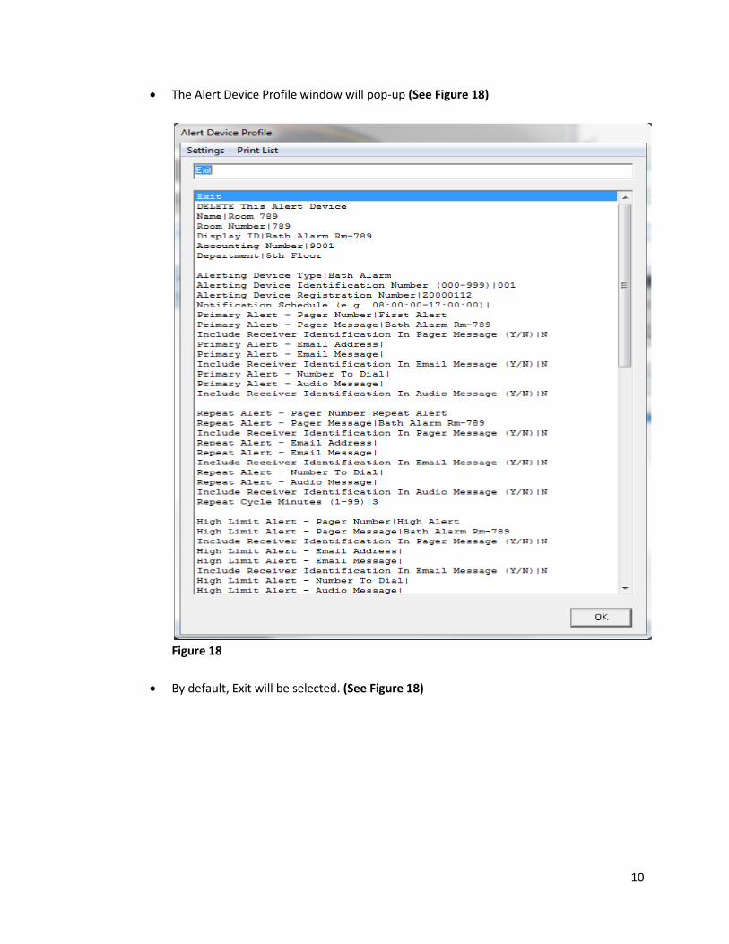
The Alert Device Profile window will pop-up (See Figure 18)
Figure 18
By default, Exit will be selected. (See Figure 18)
11
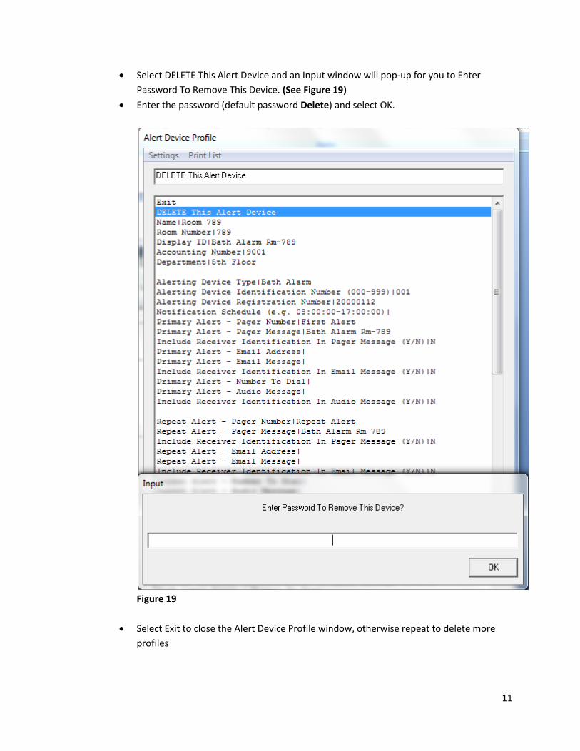
Select DELETE This Alert Device and an Input window will pop-up for you to Enter
Password To Remove This Device. (See Figure 19)
Enter the password (default password Delete) and select OK.
Figure 19
Select Exit to close the Alert Device Profile window, otherwise repeat to delete more
profiles

12
8. Alert Template
Used to start new alert/device profiles
9. Starting Alert Template
Select Alrt Temp and the Alert Device Template Setup window will pop-up.
(See Figure 20)
You can modify the current template or load an alternative template
To modify the current template, All lines below Cancel Changes and Exit in the Alert
Device Template Setup can be modified.
To modify, select lines that needs to be modify and a pop-up window will allow you to
modify it
After modification is done, you have to select Save Settings and Exit to save, otherwise
select Cancel Changes and Exit to un-do modifications and exit without saving.
Figure 20

13
To load an alternative template, select Load Alternate File in the Alert Device Template
Setup window and the Template Selection window will pop-up. (See Figure 21)
In the Template Selection window, you can choose which template you want to load
simply by selecting the name of the template. (See Figure 21)
*NOTE: *2 CUSTOM TEMPLATE CAN BE USED IF YOU KNOW THE 3 DIGIT NUMBER OF
THE ALERT/DEVICE
Once you select the template, the template will automatically pop-up and you can
modify it
To modify, select lines that needs to be modify and a pop-up window will come up
allowing you to modify it
After modification is done, you have to select Save Settings and Exit to save, otherwise
select Cancel Changes and Exit to un-do modifications and exit without saving.
Figure 21
14
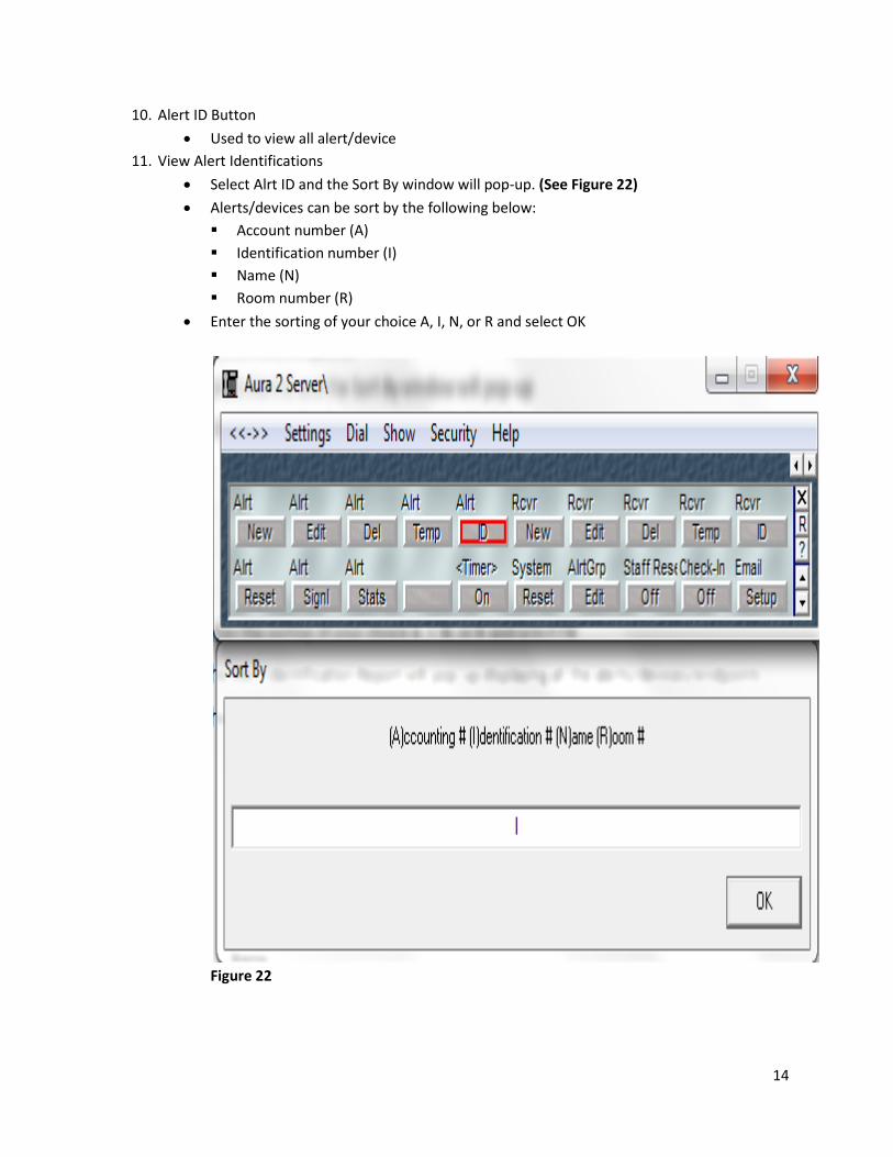
10. Alert ID Button
Used to view all alert/device
11. View Alert Identifications
Select Alrt ID and the Sort By window will pop-up. (See Figure 22)
Alerts/devices can be sort by the following below:
Account number (A)
Identification number (I)
Name (N)
Room number (R)
Enter the sorting of your choice A, I, N, or R and select OK
Figure 22

15
The Alert Identification Report will pop-up displaying all the alert/device. (See Figure 23)
The Close Device Identification Repot will contain the following fields: (See Figure 23)
Account number
Identification number
Registration number
Room number
Type
Name
Display
Close Device Identification Report will be selected by default and select OK to close the
window.
Print Device Identification Report can be selected if you want to print a list of all the
alert/device. (See Figure 23)
Must have printer connected to Aura 2.0 computer to PRINT
Figure 23

16
12. Receiver New
Used to register Receivers
13. Registering New Receiver (See Figure 24)
Select Rcvr New and the Input window will pop-up asking you to Enter New Receiver ID
Enter new receiver ID (1-99) and select OK
Figure 24
The Receiver Profile window will pop-up for you to modify. (See Figure 25)
All lines below Cancel Changes and Exit in the Receiver Profile can be modified.
To modify, select lines that needs to be modify and a pop-up window will come up allowing
you to modify it
After modification is done, you have to select Save Settings and Exit to save, otherwise
select Cancel Changes and Exit to un-do modifications and exit without saving.
Figure 25

17
14. Receiver Edit
Used to modify Receiver profiles
15. Modifying Receiver Profiles
Select Rcvr Edit and the Input window will pop-up. (See Figure 26)
In the Input window, it will ask the Receiver Registration Number (000-999)
Enter in the Receiver Registration Number and select OK
Figure 26
The Receive Profile window will pop-up. (See Figure 25)
All lines below Cancel Changes and Exit in the Receiver Profile can be modified.
To modify, select lines that needs to be modify and a pop-up window will come up allowing
you to modify it
After modification is done, you have to select Save Settings and Exit to save, otherwise
select Cancel Changes and Exit to un-do modifications and exit without saving.

18
16. Receiver Delete
Used to delete Receivers
17. Deleting Receiver
Select Rcvr Del and the Input window will pop-up. (See Figure 26)
In the Input window, it will ask the Receiver Registration Number (000-999)
Enter in the Receiver Registration Number and select OK
Figure 26

19
Figure 27
The Receive Profile window will pop-up.
By default, Exit will be selected.
Select DELETE This Receiver and an Input window will pop-up for you to Enter Password To
Delete This Receiver. (See Figure 27)
Enter the password (default password Delete) and select OK. (See Figure 27)
Select Exit to close the Receiver Profile window, otherwise repeat to delete more receivers

20
18. Receiver Template
Used to start new receiver profiles
19. Starting Receiver Template
Select Rcvr Temp and the Receiver Template Setup window will pop-up. (See Figure 28)
To modify the current template, All lines below Cancel Changes and Exit in the Receiver
Template Setup can be modified.
To modify, select lines that needs to be modify and a pop-up window will come up allowing
you to modify it
After modification is done, you have to select Save Settings and Exit to save, otherwise
select Cancel Changes and Exit to un-do modifications and exit without saving.
Figure 28
21
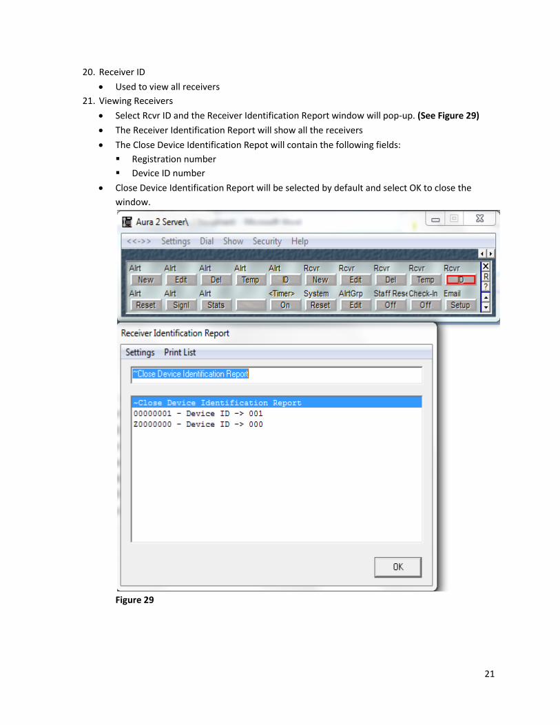
20. Receiver ID
Used to view all receivers
21. Viewing Receivers
Select Rcvr ID and the Receiver Identification Report window will pop-up. (See Figure 29)
The Receiver Identification Report will show all the receivers
The Close Device Identification Repot will contain the following fields:
Registration number
Device ID number
Close Device Identification Report will be selected by default and select OK to close the
window.
Figure 29
22
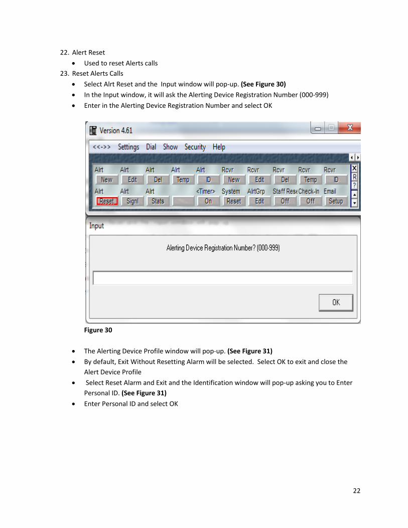
22. Alert Reset
Used to reset Alerts calls
23. Reset Alerts Calls
Select Alrt Reset and the Input window will pop-up. (See Figure 30)
In the Input window, it will ask the Alerting Device Registration Number (000-999)
Enter in the Alerting Device Registration Number and select OK
Figure 30
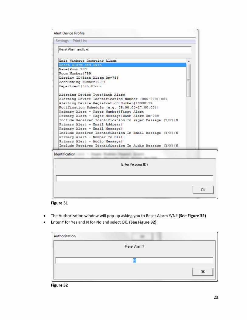
The Alerting Device Profile window will pop-up. (See Figure 31)
By default, Exit Without Resetting Alarm will be selected. Select OK to exit and close the
Alert Device Profile
Select Reset Alarm and Exit and the Identification window will pop-up asking you to Enter
Personal ID. (See Figure 31)
Enter Personal ID and select OK
23
Figure 31
The Authorization window will pop-up asking you to Reset Alarm Y/N? (See Figure 32)
Enter Y for Yes and N for No and select OK. (See Figure 32)
Figure 32
24
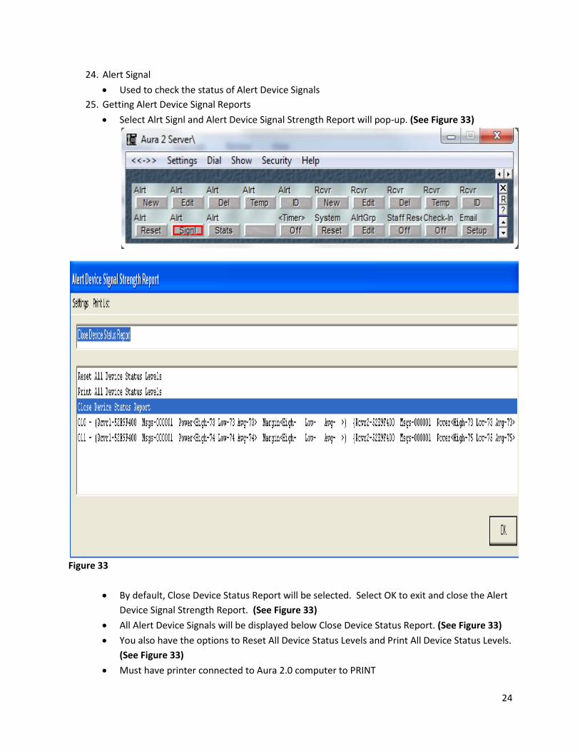
24. Alert Signal
Used to check the status of Alert Device Signals
25. Getting Alert Device Signal Reports
Select Alrt Signl and Alert Device Signal Strength Report will pop-up. (See Figure 33)
Figure 33
By default, Close Device Status Report will be selected. Select OK to exit and close the Alert
Device Signal Strength Report. (See Figure 33)
All Alert Device Signals will be displayed below Close Device Status Report. (See Figure 33)
You also have the options to Reset All Device Status Levels and Print All Device Status Levels.
(See Figure 33)
Must have printer connected to Aura 2.0 computer to PRINT

25
26. Alert Statistics
Used to get reports on Alert Statistics
27. Getting Alert Statistics Reports
Select Alrt Stats and the Sort By window will pop-up. (See Figure 34)
Alerts/devices can be sort by the following below:
Account number (A)
Identification number (I)
Name (N)
Room number (R)
Enter the sorting of your choice A, I, N, or R and select OK
Figure 34
26
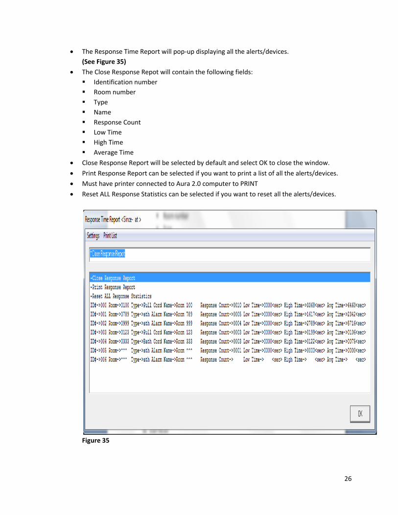
The Response Time Report will pop-up displaying all the alerts/devices.
(See Figure 35)
The Close Response Repot will contain the following fields:
Identification number
Room number
Type
Name
Response Count
Low Time
High Time
Average Time
Close Response Report will be selected by default and select OK to close the window.
Print Response Report can be selected if you want to print a list of all the alerts/devices.
Must have printer connected to Aura 2.0 computer to PRINT
Reset ALL Response Statistics can be selected if you want to reset all the alerts/devices.
Figure 35
27
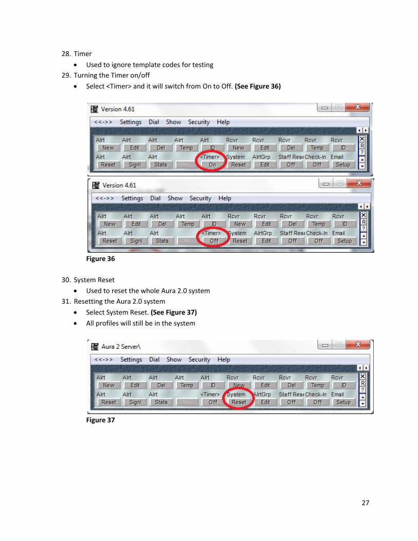
28. Timer
Used to ignore template codes for testing
29. Turning the Timer on/off
Select <Timer> and it will switch from On to Off. (See Figure 36)
Figure 36
30. System Reset
Used to reset the whole Aura 2.0 system
31. Resetting the Aura 2.0 system
Select System Reset. (See Figure 37)
All profiles will still be in the system
Figure 37

28
32. Alert Group
Used to edit a large amount of profiles to save time and limit human error
33. Editing a large amount of profiles
Select AlrtGrp Edit and the Alert Device Profile Setup window will pop-up. (See Figure 38)
By default, Exit will be selected. Select OK to exit and close the Alert Device Profile Setup
window. (See Figure 38)
Figure 38

29
Select the Range of Alert Profiles To Modify? <000-999> line and the Input window will pop-
up asking you to enter Range of Alert Profiles To Modify? <000-999>. (See Figure 39)
Enter the range of alert profiles you want to modify and select OK. (See Figure 39)
Figure 39
In the Alert Device Profile Setup window, you can modify all the lines under the Range of
Alert Profiles To Modify? <000-999> line
Select the line or lines you want to modify
After completing all the modification, select the Modify Alert Profiles line
In selecting the Modify Alert Profiles line all the alert profiles you have put in the range will
have all the modification you’ve entered
You will see Completed! after the Modify Alert Profiles line to let you know that your
modifications have been processed
Select Exit to close the Alert Device Profile Setup window
*NOTE: MAKE SURE YOU REMOVE ALL MODIFICATIONS IN THE ALERT DEVICE PROFILE
SETUP BEFORE REPEATING THE ALERT GROUP EDIT OPTION; OTHERWISE THE OLD
MODIFICATIONS WILL CARRY OVER!!!

30
34. Staff Reset
Used by staff/employee to reset their own hardware device after resetting a resident’s
alert/device
Used so residents can’t manually reset their own alert/device
35. Activate Staff Reset
Select Staff Reset to turn On or Off. (See Figure 40)
On will require staff to reset their own hardware device after resetting a resident’s
alert/device
Off will not require staff to reset their own hardware device after resetting a resident’s
alert/device
Figure 40

31
36. Check-In
Used to turn On and Off check-in times for residents and done twice a day max
37. Using Check-In
Select Check-In and the Check-In Setup window will pop-up
By default, Exit will be selected. Select OK to exit and close the Check-In Setup window.
(See Figure 41)
Figure 41
Select Automatic Generation of Check-In Alarms <On/Off> line to turn check-in On or Off
Select Daily Check-In Time1 <HHMM> line to enter in the first check-in time
Select Margin Time1 <Minutes> line to enter the amount of time a resident has from the
first check-in time to check into with the employee. Time is entered in minutes.
Select Daily Check-In Time2 <HHMM> line to enter in the second check-in time
Select Margin Time2 <Minutes> line to enter the amount of time a resident has from the
second check-in time to check into with the employee. Time is entered in minutes.
Select Display Date and Time of Last Resident Check-In line to get a report on residents
Select Cap Code To Use When Testing Resident Check-In line is used for testing individual
resident check-in Alert/Device to see if it works. Instead of going around testing every
resident’s Alert/Device, you can enter in the cap code to test the resident’s Alert/Device
Select Manual Generation of Check-In Alarms For All Residents line is used to manually run
the check-in at this very moment for all residents
Select Generate Check-In Alarm for Individual Resident line is used to manually run a check-
in for one individual at this very moment

32
38. Email
Used to set-up an email in Aura 2.0 system
Prefer using Outlook email
39. Setting up email with Outlook
**YOU WOULD NEED A FULL VERSION OF MICROSOFT OUTLOOK CLIENT SOFTWARE.
MICROSOFT EXPRESS WILL NOT WORK. A CONNECTION TO AN OUTLOOK EXCHANGE
SERVER OR POP3 EMAIL SERVER IS ALSO NEEDED.
Select Email Setup and the Email Setup window will pop-up
By default, Exit will be selected. Select OK to exit and close the Email Setup window.
(See Figure 42)
Figure 42
Select Outlook line to turn On Outlook email
Select Test Address line and the Input window will pop-up for you to enter your Test
Address
Enter your test email address and select OK
Select Test Email line and a test email will be sent to the email address you have entered
above
Check your Outlook email to see if you have received the test email

33
40. Setting up email without Outlook
Select Email Setup and the Email Setup window will pop-up
By default, Exit will be selected. Select OK to exit and close the Email Setup window.
(See Figure 42 )
Select Outlook line to turn Off Outlook email
Select Host Name line and the Input window will pop-up for you to enter your Host Name
Enter your host name and select OK
Select Login Name line and the Input window will pop-up for you to enter your Login Name
Enter your login name and select OK
Select Password line and the Input window will pop-up for you to enter your Password
Enter your password and select OK
Select Sender Address line and the Input window will pop-up for you to enter your Sender
Address
Enter your Sender Address and select OK
Select Test Email line and a test email will be sent to the email address you have entered
above
Check your email inbox to see if you have received the test email

34
SPARK Used to handle/communicate text messages to pagers and cell phones
1. Enter Maintenance Mode
Select Security --> Maintenance Level and the Security window will pop-up
Enter Password (Default password is Aura) and select OK.
2. Notify Button
Used to program text message to pagers, cell phones and group calls
3. Creating Individual/Group Contacts And Configuring Devices
Select Notify button and the Contact Select window will pop-up. (See Figure 2)
Everything under the line is individual or group contact names in the Contact Select
window. (See Figure 2)
By default, Exit is selected. Select OK to if you want close the Contact Select window.
Figure 2

35
Select *2 Add and a window will pop-up asking you to enter the New Contact Name.
(See Figure 3)
Enter the New Contact Name and select OK
Figure 3
A new window will pop-up asking you to enter Contact Number. (See Figure 4)
The Contact Number for a pager is the pager’s cap code number.
Enter the Contact Number and select OK
Figure 4
A new window will pop-up asking you to enter a Reminder for (New Contact Name?).
(See Figure 5)
You can leave this blank or put something in for Reminder and select OK
Figure 5
36
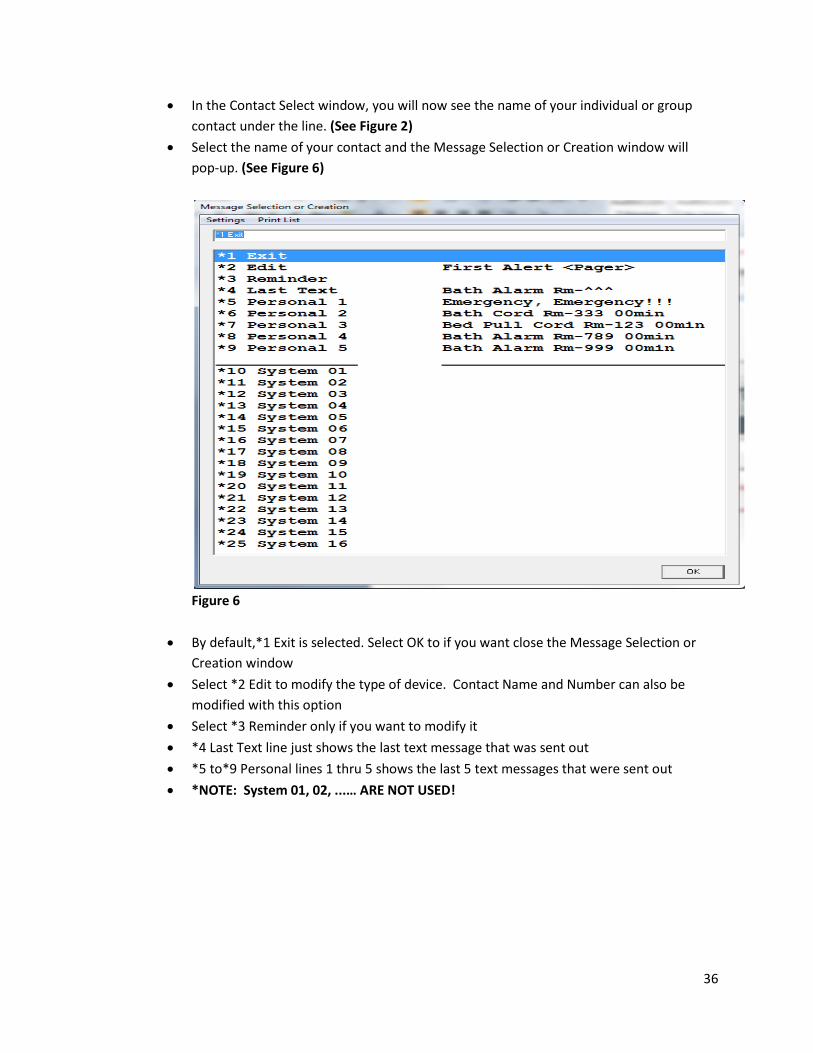
In the Contact Select window, you will now see the name of your individual or group
contact under the line. (See Figure 2)
Select the name of your contact and the Message Selection or Creation window will
pop-up. (See Figure 6)
Figure 6
By default,*1 Exit is selected. Select OK to if you want close the Message Selection or
Creation window
Select *2 Edit to modify the type of device. Contact Name and Number can also be
modified with this option
Select *3 Reminder only if you want to modify it
*4 Last Text line just shows the last text message that was sent out
*5 to*9 Personal lines 1 thru 5 shows the last 5 text messages that were sent out
*NOTE: System 01, 02, ...… ARE NOT USED!

37
4. Profile Button
Used to show Aura 2.0 system profile information. (See Figure 7)
*NOTE: NOTHING NEEDS TO BE DONE HERE!
Figure 7
5. Setup Button
*NOTE: NOT USED!

38
IMAGE LINK\Setup Prg Alerts Used to modify the Alert Notification Color Key, to program hard-wired devices and optional
Alerts
1. Enter Maintenance Mode
Select Security --> Enter Password and the Security window will pop-up
Enter Password (Default password is Aura) and select OK.
2. Setup Button
Used to modify the Alert Notification Color Key on CG Client 1 Ultimate Communicator
ImageLink 1.03 (See Figure 43)
Figure 43

39
3. Modifying The Alert Notification Color Key
Select Setup button and the Image Link Setup window will pop up on screen.
(See Figure 44)
Figure 44
By default, Save will be selected. (See Figure 44)
All lines below Cancel in the Image Link Setup window can be modified.
*NOTE: THE 1ST, 2ND, 3RD, 4TH, PRIORITY COLORS. THIS CAN BE MODIFIED TO ANY
COLOR BY SELECTING THE LINE WITH THE PRIORITY COLOR AND THE INPUT WINDOW
WILL POP-UP ASKING YOU TO ENTER A COLOR NAME. (See Figure 44)
Enter in the color name and select OK
On the Image Link Setup window select Save and OK to process the color change or
select Cancel to not process the change and close the window.

40
There is a total of 6 Alert Notifications and each has 3 parts to modify as follow below:
(See Figure 45)
1st part is the label or name of the alert
2nd part is the color of the alert
3rd part is do you want the alert to flash or not.
Select the Key Label line you want to modify and the Input window will pop-up asking
you to enter a Label Name. (See Figure 45)
Enter label name and select OK. (See Figure 45)
On the Image Link Setup window select Save and OK to process the label name change
or select Cancel to not process the change and close the window.
Figure 45
41
Select the Key Color line you want to modify and the Input window will pop-up asking
you to enter a Key Color
Enter in the Key Color and select OK,
On the Image Link Setup window select Save and OK to process the key color change or
select Cancel to not process the change and close the window.
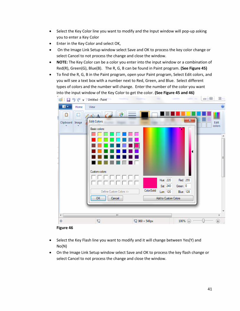
NOTE: The Key Color can be a color you enter into the input window or a combination of
Red(R), Green(G), Blue(B). The R, G, B can be found in Paint program. (See Figure 45)
To find the R, G, B in the Paint program, open your Paint program, Select Edit colors, and
you will see a text box with a number next to Red, Green, and Blue. Select different
types of colors and the number will change. Enter the number of the color you want
into the input window of the Key Color to get the color. (See Figure 45 and 46)
Figure 46
Select the Key Flash line you want to modify and it will change between Yes(Y) and
No(N)
On the Image Link Setup window select Save and OK to process the key flash change or
select Cancel to not process the change and close the window.

42
1. Prg Button
Used to program hard-wired devices
2. Programming Hard-Wired Interfaces
Select Prg button and the Input window will pop-up asking Registration for Scope (S),
PLC (P), Ext (E). (See Figure 47)
By default, PLC (P) is selected.
Enter the Registration and select OK.
Figure 47
Another Input window will pop-up asking for the Starting port number. (See Figure 48)
Enter the Starting port number and select OK.
Figure 48
Another Input window will pop-up asking for the Ending port number. (See Figure 49)
Enter the Ending port number and select OK.
Figure 49

43
The Wired Alert Ports window will pop-up showing the port numbers. (See Figure 50)
By default, Exit is selected and select OK to close Wired Alert Ports window.
*NOTE: Scope will have A, B, C and PLC will have 1, 2, 3 with the port numbers.
(See Figure 50 and 51)
A=1 --> Fast flash
B=2--> Slow flash
C=3--> Stead flash
Figure 50 - PLC
Figure 51 – Scope

44
3. Alerts Button
*NOTE: ONLY USED IF DOOR ALARMS ARE INSTALLED. (See Figure 52)
Figure 52

45
A2 Wireless – Ultimate Communicator App Link 1.35 Used to display information to see that the wireless is working Wireless battery information is displayed every 3 minutes 1. Enter Maintenance Mode
Select Security --> Maintenance Level and the Security window will pop-up
Enter Password (Default password is Aura) and select OK.
2. Configure Wireless
Select Settings and the Settings window will pop-up
Figure 53
In the Function drop down box, Inovonics EN4x00 900MHz Receiver should be selected
by default, if not set it. (See Figure 53)
In the Serial Port drop down boxes, the Port # should be set to the Serial COM port
number that the Receiver (part number RC-100E) is connected to and everything should
stay at default. (See Figure 53)
Select Start Comm and two new buttons will pop up in the Serial Port box under
Terminal Mode
Select the button with Send EN4000 Config
Select OK.
Strings of numbers should now be displaying in the module. (See Figure 53)
46
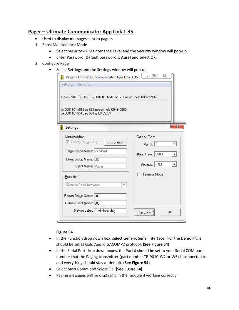
Pager – Ultimate Communicator App Link 1.35
Used to display messages sent to pagers
1. Enter Maintenance Mode
Select Security --> Maintenance Level and the Security window will pop-up
Enter Password (Default password is Aura) and select OK.
2. Configure Pager
Select Settings and the Settings window will pop-up
Figure 54
In the Function drop down box, select Generic Serial Interface. For the Demo kit, it
should be set at Gold Apollo GACOMP2 protocol. (See Figure 54)
In the Serial Port drop down boxes, the Port # should be set to your Serial COM port
number that the Paging transmitter (part number TR-9010-W2 or W5) is connected to
and everything should stay at default. (See Figure 54)
Select Start Comm and Select OK. (See Figure 54)
Paging messages will be displaying in the module if working correctly

47
A2 PI-1 Ultimate Communicator App Link 1.35 Used to display hard wired alert/device
1. Enter Maintenance Mode
Select Security --> Maintenance Level and the Security window will pop-up
Enter Password (Default password is Aura) and select OK.
2. Configure PI-1
Select Settings and the Settings window will pop-up
Figure 55
Everything except the Serial Port number will stay at the default. (See Figure 55)
In the Serial Port drop down boxes, the Port # should be set to your Serial COM port
number that the Data Collector (part number DC-064E or 128E) is connected to and
everything should stay at default. (See Figure 55)
Select Start Comm and Select OK. (See Figure 55)

48
LightControl - Ultimate Communicator App Link 1.36 Used to display light flashes
1. Enter Maintenance Mode
Select Security --> Maintenance Level and the Security window will pop-up
Enter Password (Default password is Aura) and select OK.
2. Enter Serial Port
Select Settings and the Settings window will pop-up
Figure 56
Everything except the Serial Port number will stay at the default. (See Figure 56)
In the Serial Port drop down boxes, the Port # should be set to your Serial COM port
number that the Light Controller (part number LC-064E) is connected to and everything
should stay at default. (See Figure 56)
Select Start Comm and Select OK. (See Figure 56)

49
CG Client 1 – Ultimate Communicator ImageLink 1.03 Used for Aura 2.0 User Interface
1. Enter Maintenance Mode
Select Security --> Maintenance Level and the Security window will pop-up
Enter Password (Default password is Aura) and select OK.
2. Alert Notification
Used to show which alerts/devices that needs attention
Picture of antenna will flash and beep when help is needed
3. Accessing Alert Notification
Select the antenna (Alert Notification) picture and you will see the Alert Notification
screen. (See Figure 57)
Figure 57

50
The white text boxes will contain the alerts/devices that needs attention.(See Figure 43)
Each alerts/devices will be color-coded and will be in order of emergency according to
the Alert Notification Color Key. (See Figure 43)
To return to the main user interface screen, simply just select Home.
4. Call Reporter
Used to get detailed response reports
Reports can be obtained by sorting by name, room, account and ID number
Print option is available
5. Getting Call Reports
Select the notepad with pencil (Call Reporter) picture and you will see the Call Reporter
screen. (See Figure 57 and 58)
Select which option you want to sort by. (See Figure 58)
Figure 58

51
Reports will be generated on the Response Time Report screen. (See Figure 59)
Response Time Report will display the following below: (See Figure 59)
Name
Room number
Account number
Type of alerts/devices
Count
Low time
High time
Average time
Figure 59

52
Select individual report you want to display and you will get the detailed report.
(See Figure 59 and 60)
Detailed report will contain the following below: (See Figure 60)
Date
Day of the week (DOW)
Time (military)
Duration
Receiver number
After reviewing reports you have the option to PRINT, go BACK to previous screen, or
HOME (main user interface screen). (See Figure 60)
Must have printer connected to Aura 2.0 computer to PRINT
Figure 60
53
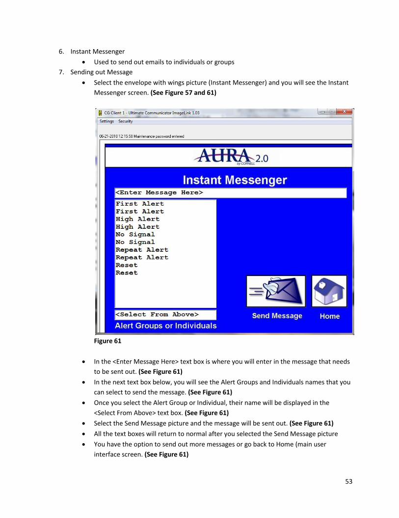
6. Instant Messenger
Used to send out emails to individuals or groups
7. Sending out Message
Select the envelope with wings picture (Instant Messenger) and you will see the Instant
Messenger screen. (See Figure 57 and 61)
Figure 61
In the <Enter Message Here> text box is where you will enter in the message that needs
to be sent out. (See Figure 61)
In the next text box below, you will see the Alert Groups and Individuals names that you
can select to send the message. (See Figure 61)
Once you select the Alert Group or Individual, their name will be displayed in the
<Select From Above> text box. (See Figure 61)
Select the Send Message picture and the message will be sent out. (See Figure 61)
All the text boxes will return to normal after you selected the Send Message picture
You have the option to send out more messages or go back to Home (main user
interface screen. (See Figure 61)
54
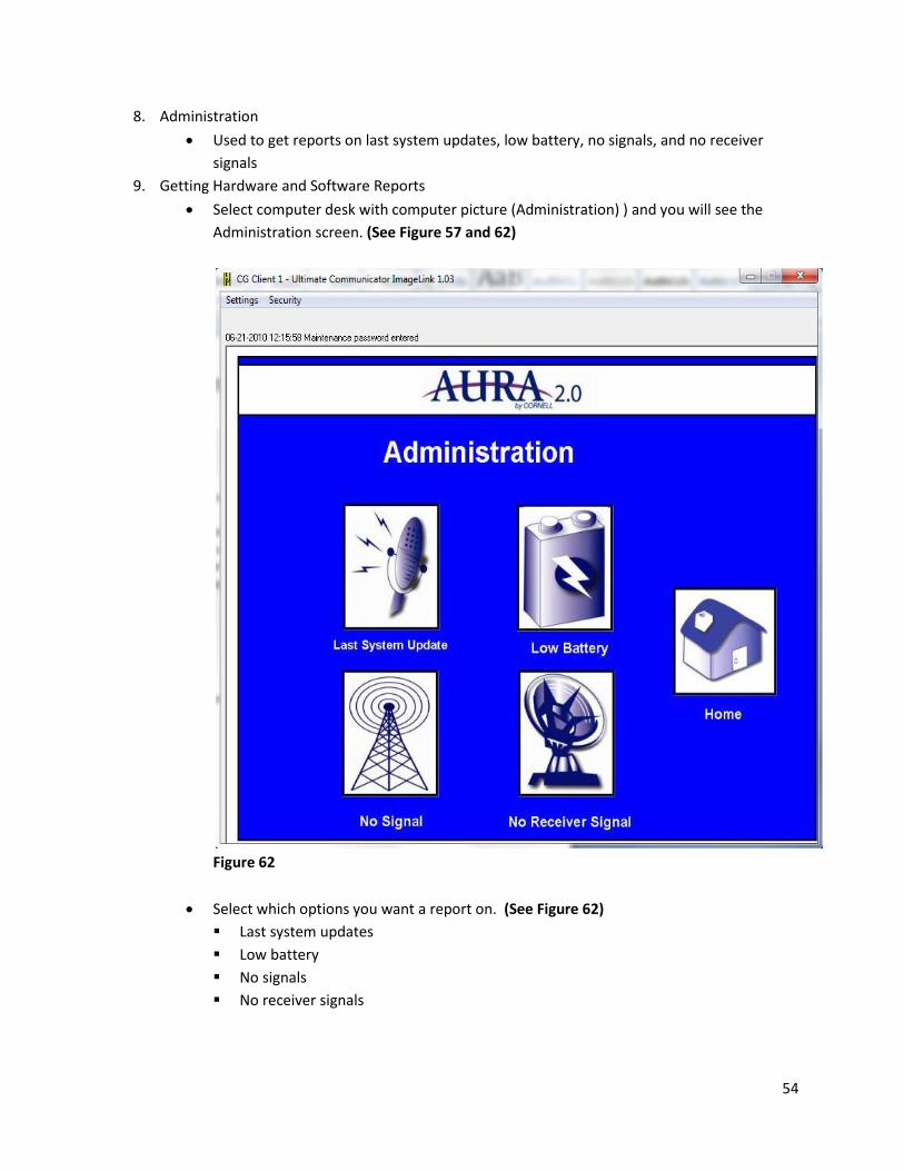
8. Administration
Used to get reports on last system updates, low battery, no signals, and no receiver
signals
9. Getting Hardware and Software Reports
Select computer desk with computer picture (Administration) ) and you will see the
Administration screen. (See Figure 57 and 62)
Figure 62
Select which options you want a report on. (See Figure 62)
Last system updates
Low battery
No signals
No receiver signals
55
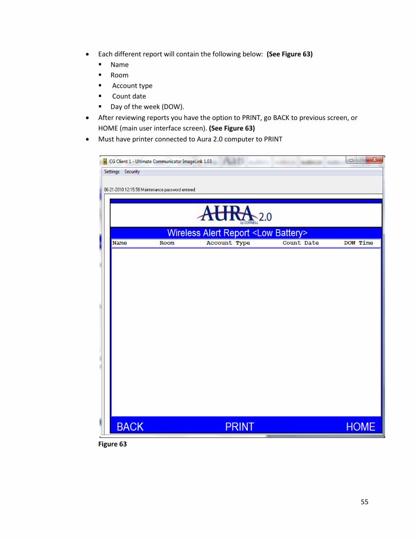
Each different report will contain the following below: (See Figure 63)
Name
Room
Account type
Count date
Day of the week (DOW).
After reviewing reports you have the option to PRINT, go BACK to previous screen, or
HOME (main user interface screen). (See Figure 63)
Must have printer connected to Aura 2.0 computer to PRINT
Figure 63

56
Ultimate Call Accounting
Used to generate detailed reports
1. Enter Maintenance Mode
Select Security - Enter Password and the Security window will pop-up. (See Figure 64)
Enter Password (Default password is Aura) and select OK. (See Figure 65)
Figure 64
Figure 65
2. Getting Reports
Select Reports -->Template Reports and the Template Reports window will pop-up.
(See Figure 66 and 67)
Figure 66

57
Figure 67
3. Specification Reports (See Figure 67)
a. Detail
Individual reports
b. Comparison
Summary of reports
c. Chronological
Arrange of reports in order

58
4. Different Types of Reports (See Figure 67)
a. Resident Requests for Help
Individual resident request for help
b. Distribution of Help Requests
Employees sharing of help requests
c. Response Times Over 5 Minutes
Employees reply time to residents over 5 minutes
d. Response Times Over 10 Minutes
Employees reply time to residents over 10 minutes
e. Response Times Over 20 Minutes
Employees reply time to residents over 20 minutes
f. First Pager Alarms Generated
1st time pager alert message goes out to employees
g. Repeat Pager Alarms Generated
2nd time pager alert message goes out to employees
h. High Limit Pager Alarms Generated
3rd time pager alert message goes out to employees
i. Check-In Received
Resident check-in received
j. Wireless Endpoint – Low Battery
Wireless hardware devices battery is low
k. Wireless Endpoint – No Signal
Wireless hardware devices has no signal
l. Wireless Receiver – No Signal
Wireless hardware receiver has no signal
5. Getting reports (See Figure 67)
Select the type and specification report (Template line will be highlighted blue)
Select which option you want:
Display Report
Save to File
Print Report
Edit Report
Close
Must have printer connected to Aura 2.0 computer to PRINT

59
6. Report Options
a. Display Report (See Figure 68)
In the Department drop down box, you can select all departments or specific
department
In the Date text box, you can select the day, week, or month
Select Continue to get report or Cancel to close window
Figure 68
b. Save to File (See Figure 67)
Select this option to save the reports to a location
c. Print Report (See Figure 67)
Select this option to print selected reports
Must have printer connected to Aura 2.0 computer to PRINT
d. Edit Report (See Figure 67)
Select this option to make change on the specification of the reports
e. Close (See Figure 67)
Select this option to close out of the Template Reports window

60
7. Custom Reports
Each blank line under each grouped template can be made into a custom report
template. (See Figure 69)
Figure 69
Select Edit Report and the Report Template window will pop up. (See Figure 70)
On the Report Characteristics tab, you can enter the name of the template in the Title
textbox. (See Figure 70)
In the Report Format, you can select the specification report with the drop down box.
(See Figure 70)
Select OK to finish/close new template report or cancel to disregard/close.
(See Figure 70)

61
Figure 70
8. Database Maintenance
Used to add departments and extensions (room, information, etc.)
9. Adding Departments
Select Maintenance --> Database and the Database Maintenance window will pop-up.
(See Figure 71)
Select the Departments/Ext. tab. (See Figure 72)
Figure 71

62
In the Departments text box, select New and the New Department window will pop-up
asking you to enter in a Department. (See Figure 72)
Enter in a Department and select OK or select Cancel to close the window.
(See Figure 72)
You also have the options to select Import, Edit, and Delete a Department.
Figure 72
10. Adding Extensions (room, information, etc.)
Select Maintenance --> Database and the Database Maintenance window will pop-up.
(See Figure 71)
Select the Departments/Ext. tab. (See Figure 73)
In the Extensions text box, select New and the New Department window will pop-up
asking you to enter in an Extension and Name. (See Figure 73)
Enter in an Extension and Name and select OK or select Cancel to close the window
You also have the options to select Sort By, Edit, and Delete a Department
Figure 73
63
11. Call Accounting.CSV File
Used to display account data and is created when you select Alrt Edit
Used when you are using the Import option in the Database Maintenance
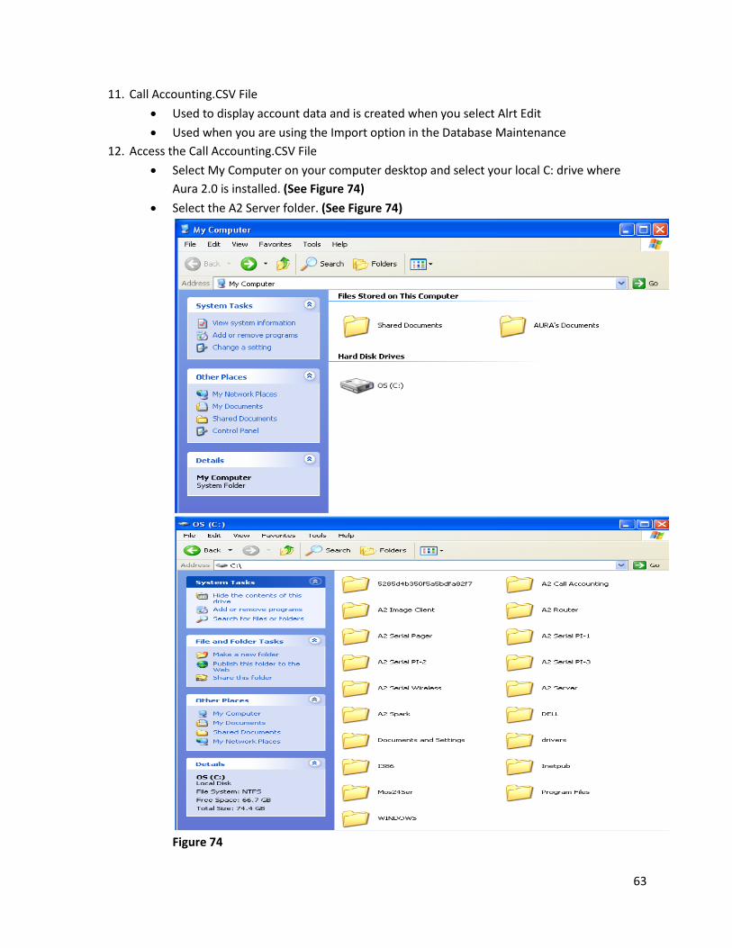
12. Access the Call Accounting.CSV File
Select My Computer on your computer desktop and select your local C: drive where
Aura 2.0 is installed. (See Figure 74)
Select the A2 Server folder. (See Figure 74)
Figure 74

64
Scroll down in the A2 Server folder and you will see the Call Accounting.CSV file.
(See Figure 75)
Right click the Call Accounting.CSV file and Select Open with Notepad. (See Figure 75)
Figure 75
In the Call Accounting.CSV file the field are displayed as followed below: (See Figure 76)
Account number
Name
Department
Figure 76