
ASSESSMENT OF SEISMIC DESIGN FOR BRIDGE IN …library.jsce.or.jp/jsce/open/00578/2009/3-0019.pdf ·...
8
1 30 ASSESSMENT OF SEISMIC DESIGN FOR BRIDGE IN VIETNAM - A LOW MODERATE SEISMIC ZONE Tran Viet HUNG 1 ・Osamu KIYOMIYA 2 ・Tongxiang AN 3 1 Graduate student, Dept. of Civil and Environmental Eng., WASEDA University, ( 169-8555 Tokyo, Shinjuku-ku, Ohkubo 3-4-1) E-mail: [email protected] 2 Dr. of Eng., Professor, Dept. of Civil and Environmental Eng., WASEDA University, ( 169-8555 Tokyo, Shinjuku-ku, Ohkubo 3-4-1) E-mail: [email protected] 3 Dr. of Eng., Research Associate of Advanced Res. Inst. For Sci. and Eng., WASEDA University, ( 169-8555 Tokyo, Shinjuku-ku, Ohkubo 3-4-1) E-mail: [email protected] This paper provides a brief review seismic design guideline for bridge in Vietnam and calculates response of bridge in a low to moderate magnitude such as Vietnam (i.e. acceleration coefficient, A= 0.00 - 0.29g). Under strong ground excitations, response of a bridge shows severe nonlinearity induced by inelastic deformation at a plastic hinge of a pier. Seismic design guidelines in the current Vietnam indicate that ground acceleration of 0.09 g or greater is likely to produce nonlinear structural response. An empirical beam seat formula indicates the upper limit of displacements due to response, since the requirement of its is predicted on the assumption of plastic response. This study is also to determine a hysteretic curvature at the plastic hinge of a pier and further to examine whether the empirical displacement formula is suitable for bridges in those seismic zones. Key Words: Seismic analysis, seismic zone, displacement, response analysis, bridge 1. INTRODUCTION Recently, the strong earthquake such as Northridge Earthquake of 1994, the Hyogoken-Nanbu Earthquake of 1995, the Taiwan Chi-Chi Earthquake of 1999, the Iran Earthquake of 2001, the Chuetsu Earthquake of 2004, and the Wengchuan Earthquake of 2008, have caused serious damage to many lifeline facilities, including bridges. Vietnam has not experienced any big earthquake damages and the history of large scale earthquakes up to now. The seismic designs for the bridges weren’t adopted until former 90's. Many seismometers are installed and some middle scale earthquakes have been recorded in Vietnam. According to the analyses of the earthquake records obtained by the seismometers, Vietnam is located at a moderated seismic activity area. However, seismic design for buildings and bridges become to be regarded as to be important in Vietnam. Specifications for bridge design in Vietnam 1) (referred to as 22TCN-272-05) was established on base of AASHTO LRFD 1998 3) in 2001, officially applied in 2005. As for an essential multi-spans bridge located moderate seismic zone, the seismic design can be conducted by single-mode elastic method or uniform load elastic method according to Vietnam Specification 1) . This paper describes a brief review on seismic design for bridge in Vietnam specification. Then, parametric studies involving a continuous multi-span bridge in Vietnam is followed. Like this, the other objective of this study is to determine response seismic of the pier bridge at the plastic zone in a low to moderate seismic zone (i.e. acceleration coefficient, A = 0.09 – 0.29g with g being the gravity acceleration), and to make sure that the empirical beam seat formula is appropriate for typical bridge in Vietnam.
Transcript of ASSESSMENT OF SEISMIC DESIGN FOR BRIDGE IN …library.jsce.or.jp/jsce/open/00578/2009/3-0019.pdf ·...

1
第 30 回土木学会地震工学研究発表会論文集
ASSESSMENT OF SEISMIC DESIGN FOR
BRIDGE IN VIETNAM - A LOW MODERATE
SEISMIC ZONE
Tran Viet HUNG1・Osamu KIYOMIYA2
・Tongxiang AN3
1 Graduate student, Dept. of Civil and Environmental Eng., WASEDA University,
(〒169-8555 Tokyo, Shinjuku-ku, Ohkubo 3-4-1)
E-mail: [email protected] 2 Dr. of Eng., Professor, Dept. of Civil and Environmental Eng., WASEDA University,
(〒169-8555 Tokyo, Shinjuku-ku, Ohkubo 3-4-1)
E-mail: [email protected] 3 Dr. of Eng., Research Associate of Advanced Res. Inst. For Sci. and Eng., WASEDA University,
(〒169-8555 Tokyo, Shinjuku-ku, Ohkubo 3-4-1)
E-mail: [email protected]
This paper provides a brief review seismic design guideline for bridge in Vietnam and calculates response of
bridge in a low to moderate magnitude such as Vietnam (i.e. acceleration coefficient, A= 0.00 - 0.29g). Under strong
ground excitations, response of a bridge shows severe nonlinearity induced by inelastic deformation at a plastic hinge
of a pier. Seismic design guidelines in the current Vietnam indicate that ground acceleration of 0.09 g or greater is
likely to produce nonlinear structural response. An empirical beam seat formula indicates the upper limit of
displacements due to response, since the requirement of its is predicted on the assumption of plastic response. This
study is also to determine a hysteretic curvature at the plastic hinge of a pier and further to examine whether the
empirical displacement formula is suitable for bridges in those seismic zones.
Key Words: Seismic analysis, seismic zone, displacement, response analysis, bridge
1. INTRODUCTION
Recently, the strong earthquake such as Northridge
Earthquake of 1994, the Hyogoken-Nanbu Earthquake of
1995, the Taiwan Chi-Chi Earthquake of 1999, the Iran
Earthquake of 2001, the Chuetsu Earthquake of 2004,
and the Wengchuan Earthquake of 2008, have caused
serious damage to many lifeline facilities, including
bridges. Vietnam has not experienced any big earthquake
damages and the history of large scale earthquakes up to
now. The seismic designs for the bridges weren’t adopted
until former 90's. Many seismometers are installed and
some middle scale earthquakes have been recorded in
Vietnam. According to the analyses of the earthquake
records obtained by the seismometers, Vietnam is located
at a moderated seismic activity area. However, seismic
design for buildings and bridges become to be regarded
as to be important in Vietnam. Specifications for bridge
design in Vietnam 1)
(referred to as 22TCN-272-05) was
established on base of AASHTO LRFD 1998 3)
in 2001,
officially applied in 2005. As for an essential multi-spans
bridge located moderate seismic zone, the seismic design
can be conducted by single-mode elastic method or
uniform load elastic method according to Vietnam
Specification 1)
.
This paper describes a brief review on seismic design
for bridge in Vietnam specification. Then, parametric
studies involving a continuous multi-span bridge in
Vietnam is followed. Like this, the other objective of this
study is to determine response seismic of the pier bridge
at the plastic zone in a low to moderate seismic zone (i.e.
acceleration coefficient, A = 0.09 – 0.29g with g being
the gravity acceleration), and to make sure that the
empirical beam seat formula is appropriate for typical
bridge in Vietnam.

2
2. BRIEF REVIEW ON SEISMIC DESIGN
FOR BRIDGE IN VIETNAM SPECIFICATION
(1) General
The current Vietnam Specifications of bridge design
published in 2005 was established according to
AASHTO LRFD 1998. This specification is also
concerned with seismic design. In this code, some objects
are modified according to Vietnam conditions. Namely
the map of maximum seismic intensity zone 1)
, the map
of a acceleration coefficient as shown in Fig. 1 2)
, the
seismic zones which is classified into three seismic zones
as presented in Table 1 1)
, the acceleration coefficients
which are adopted 0.00 to 0.29 g, etc., are modified.
However, the concept of the structure analysis and
seismic analysis are originally taken from AASHTO
LRFD 1998 3)
.
(2) Response and design spectra
When a structure responds to an applied large scale
earthquake load and live load, the corresponding
displacement may be large enough to induce nonlinear
deformation. The response spectra for elastic behavior
are fairly different than those for nonlinear behavior. The
equations and provisions specified in the design codes
are based entirely on elastic behavior analysis 1), 3), 4)
.
The earthquake load shall be taken to be horizontal
force effects determined by the product of the mass, the
response modification factor R shall be taken from 0.8 to
5.0 to depend on importance categories and bridge
components, and the elastic seismic response coefficient
Csm for the mth
vibration mode. The elastic seismic
response coefficient may be normalized using the input
ground acceleration (A) and the result plotted against the
period of vibration. This coefficient is given as following
equations 1), 3), 4)
:
AT
ASC
m
sm 5,22,1
3/2≤= (Tm ≤ 4.0 s) (1a)
3/4
3
m
smT
ASC = (Tm > 4.0 s) (1b)
and soil profiles type III, IV:
Csm = A (0.8 + 4.0Tm) (T < 0.3 s) (1c)
where Tm is the period of the mth
vibration mode (s); A is
the acceleration coefficient and it is determined in
accordance with the map of seismic zones and maximum
seismic intensity zone of Vietnam (reference to Fig. 1)
and, it was given by the Vietnam Institute of Geophysics
and provided as contour for return period of 500 years.
Maximum probable earthquake with a return period of
around 2.500 years has to be considered with the critical
bridges. S as shown in Table 2 is the site coefficient.
The structure’s period will render the bridge engineer
idea on the performance of the structure through the
design response spectra. If the period is large, it will
likely fall with the dominant displacement portion of the
spectra and displacement of the structure will be large.
Current industry practice, due largely the development of
computer hardware and software, is to perform a multi-
modal response spectrum analysis on the bridges. The
displacement demands are then determined directly from
the analysis results. It should be recognized that these
values will be inherently conservative due to the nature
of the design response spectra 7)
.
The four descriptive soil types are defined as follows 1), 3), 4)
:
+ Type I (S = 1.0): Rock of any characteristic or any
stable deposit of sands, gravels, or stiff clays less than 60
m deep and overlying rock.
Table 1 Seismic zone in Vietnam
Acceleration Coefficient Seismic zone MSK - 64 class
A ≤ 0.09 1 Class ≤ 6.5
0.09 < A ≤ 0.19 2 6.5 < Class ≤ 7.5
0.19 < A < 0.29 3 7.5 < Class ≤ 8
Table 2 Site coefficients (22TCN 272-05)
Soil profile type Site coefficient
I II III IV
S 1.0 1.2 1.5 2.0
Fig. 1 Ground acceleration zone map of Vietnam with return
period about 500 years 2)
3
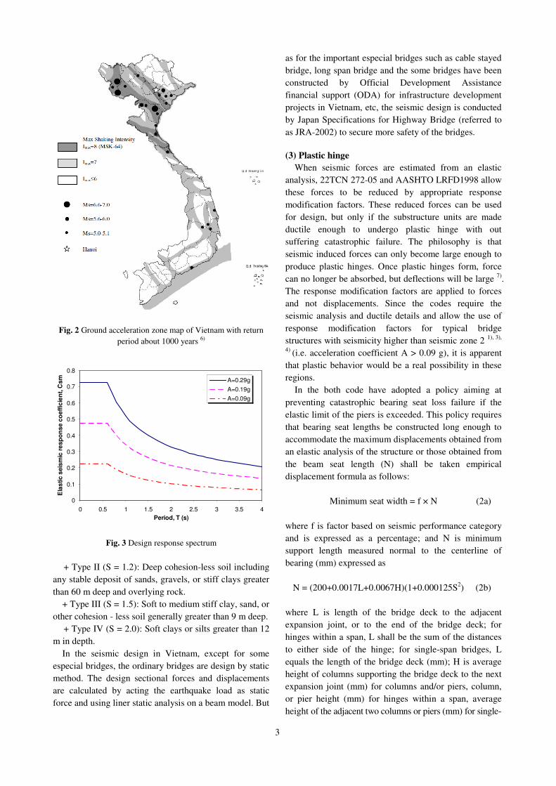
Fig. 2 Ground acceleration zone map of Vietnam with return
period about 1000 years 6)
0
0.1
0.2
0.3
0.4
0.5
0.6
0.7
0.8
0 0.5 1 1.5 2 2.5 3 3.5 4
Period, T (s)
Ela
sti
c s
eis
mic
re
sp
on
se
co
eff
icie
nt,
Csm A=0.29g
A=0.19g
A=0.09g
Fig. 3 Design response spectrum
+ Type II (S = 1.2): Deep cohesion-less soil including
any stable deposit of sands, gravels, or stiff clays greater
than 60 m deep and overlying rock.
+ Type III (S = 1.5): Soft to medium stiff clay, sand, or
other cohesion - less soil generally greater than 9 m deep.
+ Type IV (S = 2.0): Soft clays or silts greater than 12
m in depth.
In the seismic design in Vietnam, except for some
especial bridges, the ordinary bridges are design by static
method. The design sectional forces and displacements
are calculated by acting the earthquake load as static
force and using liner static analysis on a beam model. But
as for the important especial bridges such as cable stayed
bridge, long span bridge and the some bridges have been
constructed by Official Development Assistance financial support (ODA) for infrastructure development
projects in Vietnam, etc, the seismic design is conducted
by Japan Specifications for Highway Bridge (referred to
as JRA-2002) to secure more safety of the bridges.
(3) Plastic hinge
When seismic forces are estimated from an elastic
analysis, 22TCN 272-05 and AASHTO LRFD1998 allow
these forces to be reduced by appropriate response
modification factors. These reduced forces can be used
for design, but only if the substructure units are made
ductile enough to undergo plastic hinge with out
suffering catastrophic failure. The philosophy is that
seismic induced forces can only become large enough to
produce plastic hinges. Once plastic hinges form, force
can no longer be absorbed, but deflections will be large 7)
.
The response modification factors are applied to forces
and not displacements. Since the codes require the
seismic analysis and ductile details and allow the use of
response modification factors for typical bridge
structures with seismicity higher than seismic zone 2 1), 3),
4) (i.e. acceleration coefficient A > 0.09 g), it is apparent
that plastic behavior would be a real possibility in these
regions.
In the both code have adopted a policy aiming at
preventing catastrophic bearing seat loss failure if the
elastic limit of the piers is exceeded. This policy requires
that bearing seat lengths be constructed long enough to
accommodate the maximum displacements obtained from
an elastic analysis of the structure or those obtained from
the beam seat length (N) shall be taken empirical
displacement formula as follows:
Minimum seat width = f × N (2a)
where f is factor based on seismic performance category
and is expressed as a percentage; and N is minimum
support length measured normal to the centerline of
bearing (mm) expressed as
N = (200+0.0017L+0.0067H)(1+0.000125S2) (2b)
where L is length of the bridge deck to the adjacent
expansion joint, or to the end of the bridge deck; for
hinges within a span, L shall be the sum of the distances
to either side of the hinge; for single-span bridges, L
equals the length of the bridge deck (mm); H is average
height of columns supporting the bridge deck to the next
expansion joint (mm) for columns and/or piers, column,
or pier height (mm) for hinges within a span, average
height of the adjacent two columns or piers (mm) for single-

4
Table 3 Acceleration coefficients of some bridges have been constructed in Vietnam
No Name of Bridge Typical Bridge Span Layout MSK-64
Class
Acceleration
coefficient
1 Tan De Cantilever Bridge 75+3@120+70 8 0.10
2 Phu Dong Cantilever Bridge 65+7@100+65 7(8) 0.17
3 Bai Chay Cantilever Bridge 40+81+129+435+129+86 6 0.17
4 Kien Cable stayed Bridge 85+200+85 7 0.06
5 Can Tho Cable stayed Bridge 2@40+150+550+150+2@40 6 0.10
6 Thanh Tri Cantilever Bridge 80+4@130+80 8 0.17
7 Da Bac Cantilever Bridge 65+100+65 7 0.07
8 Quy Cao Cantilever Bridge 52+85+52 7 0.08
9 Non Nuoc Cantilever Bridge 42+52+85+52+42 7(8) 0.10
10 Tram Bac Cantilever Bridge 52+85+52 7 0.07
11 My Thuan Cable stayed Bridge 150+350+150 6 0.10
12 Ben Luc Cantilever Bridge 50+90+120+90+50 7 0.10
13 Nhat Tan Cable stayed Bridge 150+4@300+150 7(8) 0.12
14 Phu Long Cantilever Bridge 75+120+75 7 0.08
15 Dong Tru CFST arch bridge 80+120+80 8 0.17
16 Rao II Cable stayed Bridge - - 0.14
17 Phap Van-Cau Gie Interchange PC beam Bridge 29+29.5+3@30+29.5+29 - 0.17
18 Hoa Binh PC beam Bridge - - 0.19
Fig. 4 The profile of the highway bridge (unit is mm)
-span bridges (mm); S is skew of support measured from
line normal to span (deg).
The equation (2) has been taken originally from
AASHTO LRFD 1998 and it can often give
displacement several times larger than those obtain from
an elastic analysis.
3. PARAMETRIC STUDIES
(1) Bridge model
The profile of multi-span continuous bridge was
shown in Fig. 4. Representative of typical bridges in
Vietnam is evaluated under this study. This bridge in this
study is designed by static analysis according to the
22TCN-272-05 1)
. The superstructure is a hollow
concrete slab beam structure with 8 continuous spans.
The total length of the bridge is 250 m.
The substructure system consists of 3 rigid frame piers
(P2, P3, and P4) and 4 bent piers (P0, P1, P5 and P6).
The compressive strength of the concrete of all piers is
30 MPa; the diameter of the spiral reinforcement is 16
mm; the diameter of the longitudinal reinforcement is 25
mm and 29 mm, spacing of the spiral is 300 mm and 125
mm for P0, P1, P5, P6 and P2, P3, P4, respectively. The
rubber bearing supports (P0, P1, P5 and P6) are installed.
The basic components of the rubber bearing are
5
elastomer and steel plates. All of the pier columns and
the abutments are fabricated by reinforced concrete and
the bored cast-in-place piles are driven under the footing
as shown in Fig. 5. The pier columns are all circular with
spiral or circular lateral reinforcement as shown in Fig. 6.
The ground layer consists of medium sand, fine sand and
gravelly sand. The thickness of the surface layer is about
40 m.
(2) Analysis procedure
(a) Model
The bridge in this study is designed by the Vietnam
design code by static analysis. The stopper and rubber
bearing are installed to enhance the seismic performance.
In this study, the response analysis of the bridge is
estimated according to JRA-2002 5)
. An analytical model
of the bridge as shown in Fig. 7 is made to estimate
seismic performance of the bridge, especially bearing
capacity of the members and unseating of the girders.
The girders are replaced to linear beam elements. The
pile foundation is replaced to the horizontal spring Kx,
vertical spring Ky and rotating spring Kθ. The spring
values are calculated by Forum 8 software. The dominate
period of the surface ground is TG = 0.88 s > 0.60 s i.e.
ground type in Table 4 is type III ground. The modified
factor Cz is selected as 0.7 (region C). The concrete
block as a stopper is installed at the top of the pier. The
stopper is replaced to a spring element considering the
spacing. The rubber bearing is replaced to a bi-linear
spring element in horizontal direction.
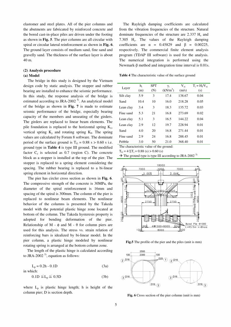
The pier has circler cross section as shown in Fig. 6.
The compressive strength of the concrete is 30MPa, the
diameter of the spiral reinforcement is 16mm and
spacing of the spiral is 300mm. The column of the pier is
replaced to nonlinear beam elements. The nonlinear
behavior of the columns is presented by the Takeda
model with the potential plastic hinge zone located at
bottom of the column. The Takeda hysteresis property is
adopted for bending deformation of the pier.
Relationship of M - φ and M - θ for column piers are
used for this analysis. The stress vs. strain relation of
reinforcing bars is idealized by bi-linear model. In the
pier column, a plastic hinge modeled by nonlinear
rotating spring is arranged at the bottom column zone.
The length of the plastic hinge is calculated according
to JRA-2002 5)
, equation as follows:
Lp = 0.2h - 0.1D (3a)
in which:
0.1D ≦Lp ≦ 0.5D (3b)
where Lp is plastic hinge length; h is height of the
column pier; D is section depth.
The Rayleigh damping coefficients are calculated
from the vibration frequencies of the structure. Natural
dominate frequencies of the structure are 2.337 Hz and
7.305 Hz. The values of the Rayleigh damping
coefficients are α = 0.45829 and β = 0.00225,
respectively. The commercial finite element analysis
program (TDAP III software) is used for the analysis.
The numerical integration is performed using the
Newmark-β method and integration time interval is 0.01s.
Table 4 The characteristic value of the surface ground
Layer hi
(m)
SPT
(N)
γt
(kN/m3)
Vsi
(m/s)
Ti = Hi/Vsi
(s)
Silt clay 5.9 3 17.4 138.67 0.04
Sand 10.4 10 16.0 218.28 0.05
Lean clay 3.4 3 18.3 135.72 0.03
Fine sand 5.3 21 16.8 273.69 0.02
Lean clay 5.1 3 16.5 144.22 0.04
Lean clay 2.9 12 19.7 228.94 0.01
Sand 4.0 20 16.8 271.44 0.01
Fine sand 2.9 24 16.8 288.45 0.01
Pebble 3.0 50 21.0 368.40 0.01
The characteristic value of the ground:
TG = 4·ΣTi = 0.88 (s) > 0.60 (s)
� The ground type is type III according to JRA-2002 5)
Fig.5 The profile of the pier and the piles (unit is mm)
2500
100 2300 100
D25
D16
D16
D16 D16
D16
D16
12
3
3
3
3
2
Fig. 6 Cross section of the pier column (unit is mm)

6
Girder (linear beam element)
Bearing spring
Stopper
Long.=0.12m
Spacing
Acting force
Disp.
K=10 kN/m
Hozi.=0.05m
8
K=10 kN/m-1
Colunm pier
Nonlinear beam element
Nonlinear rotating
Plastic hinge spring
Beam element
Footing
spring element
Foundation ground spring
P
Disp.
k
k1
Fig. 7 Modelling of the bridge pier
Max acc. is 1.41m/s2-1.5-1.0-0.50.00.51.01.52.0
0 10 20 30 40 50Time (s)Time (s)Time (s)Time (s)Acceleration (m/sAcceleration (m/sAcceleration (m/sAcceleration (m/s2222 ))))
Fig. 8 The ground acceleration records in the Tsugaru Ohhashi,
1983 (Mg = 7.7, the maximum acc. is 1.41 m/s2)
Table 5 The displacement of the top pier (unit is m)
Pier P0 P1 P2 P3 P4 P5 P6
0.002 0.007 0.013 0.013 0.013 0.007 0.002
Table 6 Moment and shear force at the plastic hinge
Shear (kN) Pier
Response Resistance
Moment
(kN·m)
P0 502.4 3854 1738
P1 1588 3854 6914
P2 4605 5229 6977
P3 4621 5229 7099
P4 3986 5229 8210
P5 1597 3854 6953
P6 505.9 3854 1751
(b) Ground motion
Base on research projects of the Vietnam Institute of
Geophysics named “Research and Forecasting
Earthquakes and Foundation Fluctuations in Vietnam”
reported recently (Nguyen Dinh Xuyen et al., 2005) and
other researchers 6), 8)
shown that Vietnam was classified
to the low moderate seismic zone, the maximum
magnitude do not exceed 6.0 on the Richter scale, but the
earthquakes of magnitude (MS) greater than 3.1 on the
Richter scale occurred in Vietnam. The focal depth of
most earthquakes is 10-20 km. Most of earthquakes did
not cause any serious damage for structures, especially
for bridge structures. However, since bridge damage due
to the design earthquake could influence on the current
life, transportation and economy, the current design code
require seismic analysis for bridge into 3 seismic zones
with acceleration coefficients from 0.00 to 0.29 g shown
in Table 1. The ground acceleration records in the
Tsugaru Ohhashi (1983), Japan is adopted as input data
at the ground level in this study (shown in Fig. 8). This
record is corresponded to Level 1 ground motion in
Japan Specification, JRA-2002 5)
and maybe corresponds
with a low moderate seismic zone in Vietnam 6)
. The
peak ground acceleration of earthquake wave is 1.41
m/s2. These ground acceleration records are adopted
because the soil condition of the construction site is
classified into Group III in the soil condition.
(3) Results and evaluation
(a) Response of the piers bridge
The results show the maximum rotation angles of the
pier, shear force and moment obtained from analysis are
smaller than there resistance (shown in Table 5 and
Table 6). Fig. 9 to Fig. 15 shows the hysteretic response
at the plastic hinge of the pier including the rubber
bearing is installed at the top of the pier P0, P1, P5 and
P6, and rigid jointed between the pier and the girder at
the pier P2, P3 and P4. The displacement at the top of
the pier is also small. The analysis shows that all piers
are still within elastic state, no serious damage is
evaluated for Level 1 earthquake motion. The bridge is
secure from the current earthquake occurring in Vietnam.
(b) Evaluation of seating length
The target of this study is to investigate whether
plastic hinge is a real possibility for typical bridge
located in a low moderate seismic zone or not. To
account for the possibility of plastic hinging and the
associated large displacement, 22TCN-272-05 requires
that the beam seat length (N) shall be taken empirical
displacement formula (equation (2)). This formula is an
estimate of displacements that may be achieved only in
the event of inelastic behavior. In this study, plastic
hinge is assumed to occur at the pier column even
though for Level 1 earthquake motion. For the typical
straight structures modeled, this study indicates that
plastic hinge at the column base is a real possibility for
bridges located in a low to moderate seismic zone.

7
Pier P0
-10000
-8000
-6000
-4000
-2000
0
2000
4000
6000
8000
10000
-0.0001 -0.00005 0 0.00005 0.0001
Rotation, θθθθ (rad)
Mo
men
t (k
N.m
)
Response
Resistance
Mc=6600.9kN.m θc=6.14x10⁻⁵rad
My=21037.9kN.m θy=6.78x10⁻⁴rad
Mu=22145.1kN.m θu=3.01x10⁻³radMy , θy
Mc, θc
Mc, θc
My , θy
Fig. 9 Hysteretic response of the pier P0 at the plastic hinge
-15000
-10000
-5000
0
5000
10000
15000
-0.0003 -0.0002 -0.0001 0 0.0001 0.0002 0.0003
Rotation, θ (rad)
Mo
men
t (k
N.m
)
Response
Resistance
v
My , θy
Mc=6520.4kN.m θc=8.54x10⁻⁵rad
My=20756.4kN.m θy =9.29x10⁻⁴rad
Mu=22224.0kN.m θu=4.18x10⁻³rad
Mc, θc
Mc, θc
Pier P1
My , θy
Fig. 10 Hysteretic response of the pier P1 at the plastic hinge
-15000
-10000
-5000
0
5000
10000
15000
-0.0002 -0.0001 0 0.0001 0.0002
Rotation, θ (rad)
Mo
men
t (k
N.m
)
Response
Resistance
My , θy
My , θy
Mc, θc
Mc, θc
Mc=6569.2kN.m θc=4.92x10⁻⁵rad
My=20895.1kN.m θy=5.34x10⁻⁴rad
Mu=22276.6kN.m θu=2.39x10⁻³rad
Pier P2
Fig. 11 Hysteretic response of the pier P2 at the plastic hinge
-15000
-10000
-5000
0
5000
10000
15000
-0.00015 -0.00005 0.00005 0.00015
Rotation, θθθθ (rad)
Mo
men
t (k
N.m
)
Response
Resistance
Mc=6487.2kN.m θc=6.08x10⁻⁵rad
My =20625.9kN.m θy=6.56x10⁻⁴rad
Mu=22302.8kN.m θu=2.97x10⁻³rad
Pier P3
Mc, θc
Mc, θc
My , θy
My , θy
Fig. 12 Hysteretic response of the pier P3 at the plastic hinge
-15000
-10000
-5000
0
5000
10000
15000
-0.0003 -0.0002 -0.0001 0 0.0001 0.0002 0.0003
Rotation, θθθθ (rad)
Mo
men
t (K
N.m
)
Response
Resistance
Mc=6569.2kN.m θc=4.92x10⁻⁵rad
My=20895.1kN.m θy=5.34x10⁻⁴rad
Mu=22276.6kN.m θu=2.39x10⁻³rad
Pier P4
Mc, θc
Mc, θc
My , θy
My , θy
Fig. 13 Hysteretic response of the pier P4 at the plastic hinge
-15000
-10000
-5000
0
5000
10000
15000
-0.0003 -0.0002 -0.0001 0 0.0001 0.0002 0.0003
Rotation, θθθθ (rad)
Mo
men
t (k
N.m
)
Response
Resistance
Mc=6520.4kN.m θc=8.54x10⁻⁵rad
My=20756.4kN.m θy =9.29x10⁻⁴rad
Mu=22224.0kN.m θu=4.18x10⁻³rad
Pier P5
Mc, θc
Mc, θc
My , θy
My , θy
Fig. 14 Hysteretic response of the pier P5 at the plastic hinge

8
-10000
-8000
-6000
-4000
-2000
0
2000
4000
6000
8000
10000
-0.0001 -0.00005 0 0.00005 0.0001
Rotation, θθθθ (rad)
Mo
men
t (k
N.m
)
Response
Resistance
Mc=6600.9kN.m θc=6.14x10⁻⁵rad
My=21037.9kN.m θy =6.78x10⁻⁴rad
Mu=22145.1kN.m θu=3.01x10⁻³rad
Pier P6
Mc, θc
Mc, θc
My , θy
My , θy
Fig. 15 Hysteretic response of the pier P6 at the plastic hinge
However, this seismic analysis with plastic hinge is
not reasonable because it is an analytical model of
typical bridge and earthquake ground motion is only 1.41
m/s2. The empirical seat length designed at the abutment
A1 for this typical bridge is N = 0.56 m with bridge
modeled. The relative displacement between the
substructure and the superstructure is defined by
dynamic response analysis is 1.4 cm for level 1 in this
study. Unseating of the girder will not be happened. The
seat length N from 22TCN-272-05 has enough length to
prevent the superstructure from departure and unseating.
5. CONCLUSIONS
The seismic design for bridge in Vietnam is review in
this paper. Current Vietnam seismic design requires that
an elastic analysis is performed to estimate design forces,
and established a lower bound for design displacements.
For the typical straight structures modeled, this study
indicates that plastic hinge at the column base may occur
in a low to moderate seismic zone such as Vietnam.
Although plastic hinge may occur, the stopper will
restrict longitudinal deflections to values below those
calculated by the empirical bearing seat formula.
For Level 1 earthquake motion according to Japan
code, no serious damage is evaluated. The bearing
capacity of the pier is still within elastic state. The bridge
is also secured from the current earthquake occurring in
Vietnam.
As the future research, more parametric studies and
other earthquake wave should be conducted to verify real
effect on bridge design in Vietnam. Since Vietnam
specification was established based on AASHTO LRFD
1998, and classification of the seismic zones, earthquake
motion etc., is different from America. Hence, to
estimate seismic assessment of bridge in Vietnam is very
important, then to modify some problems in the
Specification in order to correspond with Vietnam
conditions.
REFERENCES
1) 22TCN 272-05, Specification for Bridge Design, Ministry
of Transport of Vietnam, 2005.
2) TCXDVN 375: 2006, Design of Structures for Earthquake
Resistance, Vietnam Ministry of Construction, 2006.
3) AASHTO, Load and resistance factor design (LRFD)
specifications for highway bridges, Washington (DC):
American Association of State Highway and Transportation
Officials (AASHTO), 1998.
4) AASHTO, AASHTO LRFD Bridge design specifications, 3rd
Edition, Washington (DC): American Association of State
Highway and Transportation Officials, 2004.
5) JRA, Specification of highway bridges, Part V seismic design,
Japan Road Association, 2002.
6) T.D. Ngo, M.D. Nguyen, D.B. Nguyen, A review of the
Current Vietnamese Earthquake Design Code, Special Issue
of the Electronic Journal of Structural Engineering (EJSE):
Earthquake Engineering in the low and moderate seismic
regions of Southeast Asia and Australia, pp. 32-41, 2008.
7) Y. Frank Chen, Assessment of the current US seismic
displacement requirements for bridges in a low-moderate
seismic zone, Engineering Structures, Vol 26, pp. 1365–1379, 2004.
8) Assessment of seismic hazard at the construction site of
Nhat Tan Bridge and adjacent areas, Vietnamese Academy
of Science and Technology, Institute of Geophysics, 2007.
9) Nasim K. Shattarat, Michael D. Symans, David I. McLean,
William F. Cofer, Evaluation of nonlinear static analysis
methods and software tools for seismic analysis of highway
bridges, Engineering Structures, Vol. 30, Issue 5, pp. 1335-
1345, 2008.
10) Do Hyung Lee, Eunsoo Choi, Goangseup Zic, Evaluation
of earthquake deformation and performance for RC bridge
piers, Engineering Structures, Vol. 27, pp. 1451-1464, 2005.