Aspen PFD Pilot's Guide°©문 중인 사이트에서 설명을 제공하지 않습니다.
182
-
Upload
duongkhuong -
Category
Documents
-
view
221 -
download
1
Transcript of Aspen PFD Pilot's Guide°©문 중인 사이트에서 설명을 제공하지 않습니다.


EFD1000 PFD Pilot’s Guide Page iiiA-01-184-00 REV C / 091-00005-001 REV ( )
EFD1000 PFD Pilot’s GuidePage iv A-01-184-00 REV C / 091-00005-001 REV ( )
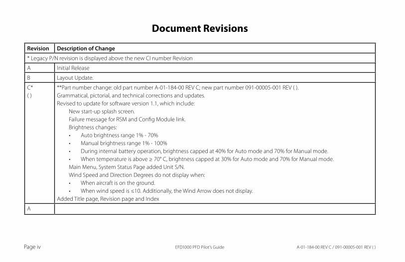
Document Revisions
Revision Description of Change
* Legacy P/N revision is displayed above the new CI number Revision
A Initial Release
B Layout Update.
C* ( )
**Part number change: old part number A-01-184-00 REV C; new part number 091-00005-001 REV ( ).Grammatical, pictorial, and technical corrections and updates.Revised to update for software version 1.1, which include:
New start-up splash screen.Failure message for RSM and Config Module link.Brightness changes:
Auto brightness range 1% - 70%•Manual brightness range 1% - 100%•During internal battery operation, brightness capped at 40% for Auto mode and 70% for Manual mode.•When temperature is above ≥ 70° C, brightness capped at 30% for Auto mode and 70% for Manual mode. •
Main Menu, System Status Page added Unit S/N.Wind Speed and Direction Degrees do not display when:
When aircraft is on the ground.•When wind speed is ≤10. Additionally, the Wind Arrow does not display. •
Added Title page, Revision page and Index
A
EFD1000 PFD Pilot’s Guide Page vA-01-184-00 REV C / 091-00005-001 REV ( )
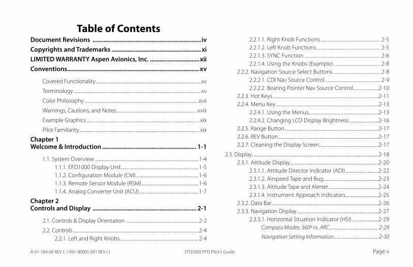
Table of ContentsDocument Revisions .................................................................... ivCopyrights and Trademarks ........................................................xiLIMITED WARRANTY Aspen Avionics, Inc. ...............................xiiConventions...................................................................................xv
Covered Functionality ................................................................................................... xv
Terminology ........................................................................................................................ xv
Color Philosophy ............................................................................................................xvii
Warnings, Cautions, and Notes............................................................................ xviii
Example Graphics ........................................................................................................... xix
Pilot Familiarity .................................................................................................................. xix
Chapter 1Welcome & Introduction ........................................................... 1-1
1.1. System Overview ..................................................................................................1-41.1.1. EFD1000 Display Unit....................................................................... 1-51.1.2. Configuration Module (CM) ......................................................... 1-61.1.3. Remote Sensor Module (RSM) .................................................... 1-61.1.4. Analog Converter Unit (ACU) ...................................................... 1-7
Chapter 2Controls and Display ................................................................. 2-1
2.1. Controls & Display Orientation ....................................................................2-2
2.2. Controls .......................................................................................................................2-42.2.1. Left and Right Knobs ........................................................................ 2-4
2.2.1.1. Right Knob Functions ....................................................... 2-52.2.1.2. Left Knob Functions ........................................................... 2-52.2.1.3. SYNC Function ...................................................................... 2-62.2.1.4. Using the Knobs (Example) ........................................... 2-8
2.2.2. Navigation Source Select Buttons ............................................ 2-82.2.2.1. CDI Nav Source Control ................................................... 2-92.2.2.2. Bearing Pointer Nav Source Control .......................2-10
2.2.3. Hot Keys .................................................................................................2-112.2.4. Menu Key ..............................................................................................2-13
2.2.4.1. Using the Menus................................................................2-132.2.4.2. Changing LCD Display Brightness ...........................2-16
2.2.5. Range Button ......................................................................................2-172.2.6. REV Button ............................................................................................2-172.2.7. Cleaning the Display Screen ......................................................2-17
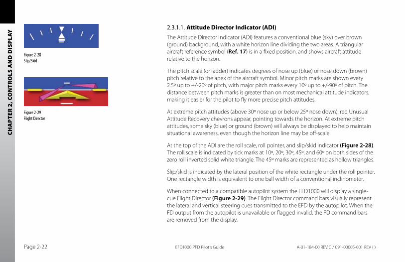
2.3. Display .......................................................................................................................2-182.3.1. Attitude Display .................................................................................2-20
2.3.1.1. Attitude Director Indicator (ADI) ..............................2-222.3.1.2. Airspeed Tape and Bug ..................................................2-232.3.1.3. Altitude Tape and Alerter ..............................................2-242.3.1.4. Instrument Approach Indicators ..............................2-25
2.3.2. Data Bar ..................................................................................................2-262.3.3. Navigation Display ...........................................................................2-27
2.3.3.1. Horizontal Situation Indicator (HSI) ........................2-29Compass Modes: 360º vs. ARC ............................................ 2-29
Navigation Setting Information ........................................ 2-30
EFD1000 PFD Pilot’s GuidePage vi A-01-184-00 REV C / 091-00005-001 REV ( )
Course Pointer and Deviation Indicator (CDI) ............. 2-30
Deviation Off Scale Indication ........................................... 2-31
Auto Course Select ................................................................... 2-31
Ground Track Indicator.......................................................... 2-32
2.3.3.2. Rate of Turn Indicator ......................................................2-322.3.3.3. Vertical Speed Indicator (VSI) .....................................2-332.3.3.4. Bearing Pointers .................................................................2-332.3.3.5. Situational Awareness Map Display ........................2-34
Chapter 3Flying the EFD1000 Pro PFD ..................................................... 3-1
3.1. Quick Controls Overview .................................................................................3-3
3.2. Example Flight Scenario ...................................................................................3-43.2.1. Pre-Departure (Startup) .................................................................. 3-53.2.2. Departure ..............................................................................................3-143.2.3. En Route ................................................................................................3-163.2.4. Arrival and Approach to Landing ...........................................3-17
3.3. Conclusion..............................................................................................................3-20
Chapter 4Reference Guide ......................................................................... 4-1
4.1. Attitude Display......................................................................................................4-24.1.1. Attitude Indicator ............................................................................... 4-2
4.1.1.1. Roll Scale................................................................................... 4-34.1.1.2. Slip/Skid Indicator ............................................................... 4-34.1.1.3. Pitch Scale ................................................................................ 4-34.1.1.4. Flight Director ........................................................................ 4-3
4.1.1.5. Air Data and Attitude/Heading Reference System (ADAHRS) .................................................................................................. 4-44.1.1.6. Degraded ADAHRS Performance ............................... 4-54.1.2. Airspeed Indicator .................................................................. 4-64.1.2.1. Selected Airspeed .............................................................. 4-84.1.2.2. Airspeed Display .................................................................. 4-8
4.1.3. Altimeter ................................................................................................4-104.1.3.1. Barometric Pressure Adjustment (BARO) ............4-114.1.3.2. Selected Altitude ...............................................................4-134.1.3.3. Altitude Level-Off and Deviation Alert .................4-134.1.3.4. MINIMUMS Alert ................................................................4-144.1.3.5. Decision Height Annunciation ..................................4-154.1.3.6. Altitude Display ..................................................................4-16
4.2. Data Bar ....................................................................................................................4-174.2.1. True Airspeed ......................................................................................4-184.2.2. Ground Speed ....................................................................................4-184.2.3. Outside Air Temperature ..............................................................4-184.2.4. Wind Speed, Direction, and Arrow .........................................4-194.2.5. Barometric Pressure Setting Display .....................................4-19
4.3. Navigation Display ............................................................................................4-204.3.1. Compass ...............................................................................................4-21
4.3.1.1. 360° Compass Mode .......................................................4-214.3.1.2. ARC Compass Mode ........................................................4-21
4.3.2. Course Pointer ..................................................................................4-244.3.3. TO/FROM Indicator ..........................................................................4-254.3.4. Course Deviation Indicator and Scale ..................................4-264.3.5. CDI Navigation Source ..................................................................4-27
EFD1000 PFD Pilot’s Guide Page viiA-01-184-00 REV C / 091-00005-001 REV ( )
4.3.6. Auto Course ........................................................................................4-304.3.7. CDI Selected Course ......................................................................4-324.3.8. Bearing Pointer Source Selection ..........................................4-334.3.9. Selected Heading and Heading Bug ....................................4-364.3.10. Aircraft Heading Display ............................................................4-374.3.11. Rate of Turn Indicator ..................................................................4-384.3.12. Map Underlays ................................................................................4-39
4.3.12.1. Map Display and Range ..............................................4-404.3.12.2. Flight Plan ...........................................................................4-424.3.12.3. Map Data Source and Reversion ...........................4-42
4.3.13. Track Indicator ................................................................................4-43
4.4. Lateral and Vertical Deviation Indicator ...............................................4-434.4.1. Lateral Deviation Indicator .........................................................4-444.4.2. Vertical Deviation Indicator .......................................................4-45
4.5. Vertical Speed Indicator .................................................................................4-45
4.6. Autopilot Integration .......................................................................................4-474.6.1. GPS Steering (GPSS) ........................................................................4-484.6.2. Flight Director.....................................................................................4-494.6.3. Typical Autopilot Operations .....................................................4-50
Chapter 5Customizing the EFD1000 PFD ................................................ 5-1
5.1. Using the Menu System ....................................................................................5-1
5.2. Customizing the Map (Declutter) ...............................................................5-6
5.3. Configuring V-speeds .........................................................................................5-8
5.4. LCD Brightness Control ..................................................................................5-13
Chapter 6Emergency and Abnormal Procedures .................................. 6-1
6.1. In Flight AHRS Reset ............................................................................................6-1
6.2. Pitot/Static System Blockage .........................................................................6-3
6.3. Loss of External Power .......................................................................................6-4
6.4. Power Override .......................................................................................................6-4
6.5. Abnormal Shutdown Procedure .................................................................6-6
6.6. Warning, Caution, and Advisory Summary ...........................................6-7
Chapter 7Appendices .................................................................................. 7-1
7.1. Operating Limitations ........................................................................................7-17.1.1. Weight & Center of Gravity ........................................................... 7-17.1.2. RSM GPS Usage ................................................................................... 7-17.1.3. Geographic Limitation .................................................................... 7-17.1.4. Placards and Decals .......................................................................... 7-27.1.5. Seaplane Operation .......................................................................... 7-2
7.2. Software Versions ..................................................................................................7-3
7.3. Specifications ...........................................................................................................7-57.3.1. EFD1000 Display Unit....................................................................... 7-57.3.2. Remote Sensor Module (RSM) ................................................... 7-77.3.3. Analog Converter Unit (ACU) ...................................................... 7-77.3.4. Operational Specifications ............................................................ 7-8
7.4. Acronyms and Abbreviations ........................................................................7-9
7.5. Index ..........................................................................................................................7-11
EFD1000 PFD Pilot’s GuidePage viii A-01-184-00 REV C / 091-00005-001 REV ( )
Table of TasksChapter 2
Control Knob SYNC Function (Figure 2-3) ......................................................2-6
How to Set the Heading Bug (HDG) ..................................................................2-8
Access and Navigate the Menus .......................................................................2-15
Edit Main Menu Items ..............................................................................................2-16
Chapter 3Control Knobs (see 2.2.1 for detail) .....................................................................3-3
Navigation Source Buttons (see 2.2.2 for detail) .........................................3-4
Hot Keys (see 2.2.3 for details) ................................................................................3-4
Set the Barometric Pressure ....................................................................................3-7
Set the Heading Bug ....................................................................................................3-8
Select The CDI Navigation Source .......................................................................3-9
Select Bearing Pointer Nav Sources ....................................................................3-9
Select Map Level of Detail .....................................................................................3-10
Change The Map Range .........................................................................................3-11
Set the Altitude Alerter ............................................................................................3-12
Set the Airspeed Bug ................................................................................................3-13
Select a Compass Mode .........................................................................................3-17
Chapter 4Set Selected Airspeed (Bug) ....................................................................................4-8
Hide/Display Airspeed Tape ....................................................................................4-9
Set Barometric Units of Measure .......................................................................4-11
Set The Barometric Pressure .................................................................................4-12
Set Selected Altitude (Bug) ...................................................................................4-13
Display/Hide Minimums .........................................................................................4-14
Set Altitude Minimum .............................................................................................4-15
Hide/Display Altitude Tape ...................................................................................4-16
Select ARC CDI/HSI Compass Mode ...............................................................4-22
Select Compass Type ................................................................................................4-23
Select The CDI Navigation Source ....................................................................4-28
Enable AUTOCRS .........................................................................................................4-30
Disable AUTOCRS ........................................................................................................4-31
Select CDI Course ......................................................................................................4-32
Select The Single-Line Bearing Pointer Source ........................................4-35
Select The Double-Line Bearing Pointer Source......................................4-35
Heading Bug Set ..........................................................................................................4-37
Display Map ....................................................................................................................4-40
Set Map Range .............................................................................................................4-41
Enable/Disable GPSS .................................................................................................4-49
“HDG” Mode Operation – Heading Bug Steering ...................................4-51
“HDG” Mode Operation – GPS Steering (GPSS) ........................................4-51
“NAV” Mode Operation – VLOC Navigation ................................................4-51
EFD1000 PFD Pilot’s Guide Page ixA-01-184-00 REV C / 091-00005-001 REV ( )
“NAV” Mode Operation – GPS Navigation ...................................................4-52
“APPR” Mode Operation – ILS Approach with Vectors to Final ....................................................................................................................................4-52
“APPR” Mode Operation – GPS or GPS/RNAV APV WAAS Approach ........................................................................................................................4-53
GPS “APPR” Mode Operation – WAAS GPS Underlay to ILS Approach Using Pilot Nav ..............................................................................4-54
GPS “APPR” Mode Operation – WAAS GPS Underlay to ILS Approach With ATC Vectors to Final ........................................................4-55
Chapter 5Set Map Symbol Display ...........................................................................................5-6
ENABLE V-speed Textual Labels .........................................................................5-11
Set Textual V-speed Labels ....................................................................................5-12
Switch Brightness Mode .........................................................................................5-13
Adjust Display Brightness Manually ................................................................5-13
Chapter 6Reset the AHRS ................................................................................................................6-2
When Pitot or Static Line is Blocked ...................................................................6-3
To Override the Automatic Power Configuration ......................................6-4
View External Power Status .....................................................................................6-5
View External Voltage Status ...................................................................................6-5
View Internal Battery Status ....................................................................................6-5
Power Off Manually ......................................................................................................6-6
Power On Manually ......................................................................................................6-6
Chapter 7To View the Main Application Processor Software Version ..................7-3
To View the Input/Output Processor Software Version ..........................7-3
To View the Feature Load ..........................................................................................7-4
To View the Unit Serial Number ............................................................................7-4

EFD1000 PFD Pilot’s GuidePage x A-01-184-00 REV C / 091-00005-001 REV ( )
EFD1000 PFD Pilot’s Guide Page xiA-01-184-00 REV C / 091-00005-001 REV ( )
Copyrights and Trademarks Copyright 2007-2009.
Aspen Avionics® is a registered trademark of Aspen Avionics, Inc. Evolution™, EFD1000 Pro PFD™, EFD1000™, and the Aspen Avionics logo are trademarks of Aspen Avionics, Inc. These trademarks may not be used without the express permission of Aspen Avionics, Inc. All rights reserved.
All other trademarks are the property of their respective companies.
No part of the Pilot’s Guide may be reproduced, copied, stored, transmitted, or disseminated, for any reason, without the express written permission of Aspen Avionics, Inc. Aspen Avionics hereby grants permission to download a single copy, and any revision, of the Pilot’s Guide onto a hard drive or other electronic storage medium for personal use, provided that such electronic or printed copy of the Pilot’s Guide or revision must contain the complete text of this copyright notice and provided further that any unauthorized commercial distribution of the Pilot’s Guide or revision hereto is strictly prohibited.
The FAA has approved the EFD1000 Pro PFD under the following TSOs:
TSO-C2d, TSO-C3d, TSO-C4c, TSO-C6d, TSO-C8d, TSO-C10b, TSO-C106, TSO-C113
The following certification levels also apply to this product:
Environmental Certification Level: RTCA DO-160E
Software Certification Level: RTCA DO-178B Level C
This Pilot’s Guide provides information on the use and operation of the Evolution Flight Display 1000 Pro Primary Flight Display (EFD1000 Pro PFD). This guide is current as of the Date Published. Specifications and operational details are subject to change without notice when using an earlier or later software version. Please visit the Aspen Avionics web site for the most up-to-date Pilot’s Guide.
Installation of the EFD1000 Pro PFD in a type-certificated aircraft must be performed in accordance with the latest revision of the Aspen Avionics EFD1000 Pro PFD Installation Manual, document number A-01-126-00 /
Aspen Avionics, Inc. 5001 Indian School Road NE Albuquerque, NM 87110
Phone: (505) 856-5034 Fax: (505) 314-5440
www.aspenavionics.com
Date Published: June 15, 2009
EFD1000 PFD Pilot’s GuidePage xii A-01-184-00 REV C / 091-00005-001 REV ( )
LIMITED WARRANTY Aspen Avionics, Inc.
1. YOUR WARRANTY. Aspen Avionics, Inc. (“Aspen”) warrants to you, the original purchaser, that its Products (if purchased from an authorized dealer) will comply with applicable specifications (as set forth in the owner’s manual) in all material respects and will be free from material defects in workmanship or materials for a period of twenty-four (24) months beginning with the date that the aircraft in which the Product has been installed has been returned to service following installation by an Aspen authorized dealer (“Return to Service Date”). “Product” means new end equipment or hardware items, replaceable units and components of those units.
2. YOUR REMEDY. During the term of this warranty, Aspen will repair or replace, at its discretion, without charge (see Section 13 below for information on covered transportation costs), any Product that does not comply with the warranty of Section 1 above (a “Nonconforming Product”), so long as the warranty claim is timely submitted and the procedures in Section 14 (below) are followed. Aspen warrants repaired and/or replacement items only for the unexpired portion of the original warranty period, or, if the warranty has expired, for six months from Aspen’s shipment of the repaired or replacement Product.
3. CONDITIONS TO COVERAGE. Aspen’s obligation under this warranty is conditioned on your fulfillment of the obligation to:
A. Maintain records accurately reflecting operating time of and maintenance performed on the Product,
B. Furnish proof sufficient to establish that the item is a Nonconforming Product, and
C. Allow Aspen access to all relevant records in order to substantiate your warranty claim.
4. EXCLUSIONS. The following are not covered by (and are expressly excluded from) this warranty:
A. Normal wear and tear and the need for regular overhaul and maintenance,
B. Exposure of the Product to temperature, environmental, operating, or other conditions other than those prescribed in the owner’s manual,
C. Failure to install or operate the Product as prescribed in the owner’s manual or as Aspen otherwise directs,
D. Alterations or repairs made by anyone other than Aspen or its authorized service center,
EFD1000 PFD Pilot’s Guide Page xiiiA-01-184-00 REV C / 091-00005-001 REV ( )
E. Maintenance, repair, installation, handling, transportation, storage, operation (including, without limitation, operation of the product’s software or host medium), or use which is improper or otherwise does not comply with Aspen’s instructions as set forth in the owner’s manual,
F. Accident, contamination, damage from a foreign object or weather conditions, abuse, misuse, neglect, or negligence,
G. Exposure of the product or the product’s host medium to any computer virus or other intentionally disruptive, destructive, or disabling computer code, and
H. Any damage precipitated by failure of a product Aspen has supplied that is not under warranty or by any product supplied by someone else.
5. INVALIDATION OF WARRANTY. This warranty is void if the product is altered or repair is attempted or made by anyone other than Aspen or its authorized service center.
6. WARRANTY CARD. The Return to Service Date must be included in an accurately completed Aspen warranty application form submitted by the installing authorized dealer within 30 days of the Return to Service Date. The warranty application must be signed by the authorized repairman who certifies that the equipment has been safely and properly installed in accordance with all Aspen supplied technical information and in accordance with all applicable FAA procedures and requirements. The warranty application form must note the repairman’s FAA certificate
number to be valid. FAILURE TO COMPLETE AND RETURN THE WARRANTY CARD MAY RESULT IN DENIAL OF WARRANTY CLAIMS. MAKING CERTAIN THAT THE WARRANTY CARD IS COMPLETED, SIGNED, AND RETURNED IS YOUR RESPONSIBILITY.
7. SOLE REMEDY. Aspen’s sole obligation, and your exclusive remedy under this warranty, is limited to either the repair or replacement, at Aspen’s option, of any Nonconforming Product as provided herein.
8. EXCLUSIVE WARRANTY. THIS WARRANTY IS EXCLUSIVE AND IN LIEU OF ALL OTHER WARRANTIES. THE IMPLIED WARRANTY OF MERCHANTABILITY AND IMPLIED WARRANTY OF FITNESS FOR A PARTICULAR PURPOSE, AS WELL AS ALL OTHER IMPLIED WARRANTIES (STATUTORY OR OTHERWISE) EXPIRE AT THE END OF THE WARRANTY PERIOD PRESCRIBED IN SECTION 1.
Some States do not allow limitations on how long an implied warranty lasts, so the above limitation may not apply to you.
9. INCIDENTAL DAMAGES. ASPEN SHALL NOT UNDER ANY CIRCUMSTANCES BE LIABLE FOR ANY SPECIAL, DIRECT, INDIRECT, INCIDENTAL OR CONSEQUENTIAL LOSS OR DAMAGES OF ANY KIND (INCLUDING WITHOUT LIMITATION: DAMAGES FOR LOSS OF PROFITS, LOSS OF REVENUES, OR LOSS OF USE OR BUSINESS INTERRUPTION), EVEN IF ASPEN HAS BEEN ADVISED OF THE POSSIBILITY OR CERTAINTY OF THOSE DAMAGES OR IF ASPEN COULD HAVE REASONABLY FORESEEN THOSE DAMAGES.
Some states do not allow the exclusion of incidental or consequential damages, so the preceding limitations may not apply to you.
EFD1000 PFD Pilot’s GuidePage xiv A-01-184-00 REV C / 091-00005-001 REV ( )
10. LIMITATION OF LIAbILITY. ASPEN’S AGGREGATE LIABILITY HEREUNDER, WHETHER BASED UPON CONTRACT, TORT (INCLUDING NEGLIGENCE AND STRICT LIABILITY), INDEMNITY, OR OTHERWISE, WILL NOT EXCEED THE PRICE PAID BY YOU FOR THE WARRANTED PRODUCT. THE EXCLUSIONS OF TYPES OF DAMAGES CONTAINED HEREIN WILL BE DEEMED INDEPENDENT OF, AND WILL SURVIVE, ANY FAILURE OF THE ESSENTIAL PURPOSE OF ANY LIMITED REMEDY UNDER THE TERMS OF ANY AGREEMENT.
11. EXTENSION OF WARRANTY. No extension of this warranty will be binding upon Aspen unless set forth in writing and signed by Aspen’s authorized representative.
12. DEALER WARRANTIES. Any express or implied warranty or remedy in addition to or different from those stated herein that is offered by a dealer (“Dealer Warranty”) will be the sole responsibility of the dealer, who will be solely responsible for all liability, loss, cost, damage, or expense arising out of or in connection with any such Dealer Warranty. Although Aspen provides training and assistance to dealers, it cannot control the installation of its Products by its dealers, which are independent businesses not owned or controlled by Aspen.
13. TRANSPORTATION COSTS. Aspen will assume round trip transportation costs for a Product determined by Aspen to be a Nonconforming Product in an amount not to exceed normal (non express) shipping charges within the continental United States. You are responsible for all import/export fees, taxes, duties, customs, documentation fees, clearance fees, and similar fees and charges. You may contact Aspen to obtain a freight courier account number for prepaid shipping of the return. If Aspen subsequently determines that the Product is not a
Nonconforming Product, that this warranty is inapplicable, that the Product is out of warranty, that the defect or malfunction is excluded from coverage, or that the warranty is invalid, Aspen will invoice you for repair or replacement costs and the shipping costs. Risk of loss or damage for any Product in transit will be borne by the party initiating the transportation.
14. WARRANTY PROCEDURE. If you require warranty service, you may contact your local Aspen Authorized Dealer or you may contact Aspen directly as described below. An original or copy of the sales receipt from the original Aspen Authorized dealer will be required to obtain any warranty service. You may contact Aspen for warranty service directly by calling Aspen Customer Service at (505) 856-5034; by writing to Aspen Customer Service Department, Aspen Avionics, Inc., 5001 Indian School Road NE, Albuquerque, New Mexico, 87110; or by visiting the Aspen Website at http://www.aspenavionics.com.
This warranty gives you specific legal rights, and you may also have other rights which vary from State to State.
EFD1000 PFD Pilot’s Guide Page xvA-01-184-00 REV C / 091-00005-001 REV ( )
ConventionsThe following conventions, definitions, terminology, and colors are used in this manual and on the EFD1000 PFD.
Covered FunctionalityThis guide covers all the functionality available in the EFD1000 Pro PFD.
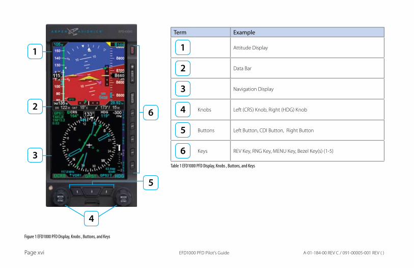
TerminologyFigure 1 shows a typical EFD1000 Pro PFD display. This guide uses the terminology listed in Table 1 when referring to specific parts of the EFD1000 Pro PFD. Chapter 4 provides an in-depth discussion and step-by-step instructions for all the available functionality of the EFD1000 Pro PFD.
EFD1000 PFD Pilot’s GuidePage xvi A-01-184-00 REV C / 091-00005-001 REV ( )
Term Example
Attitude Display
Data Bar
Navigation Display
Knobs Left (CRS) Knob, Right (HDG) Knob
Buttons Left Button, CDI Button, Right Button
Keys REV Key, RNG Key, MENU Key, Bezel Key(s) (1-5)
Table 1 EFD1000 PFD Display, Knobs , Buttons, and Keys
Figure 1 EFD1000 PFD Display, Knobs , Buttons, and Keys
EFD1000 PFD Pilot’s Guide Page xviiA-01-184-00 REV C / 091-00005-001 REV ( )
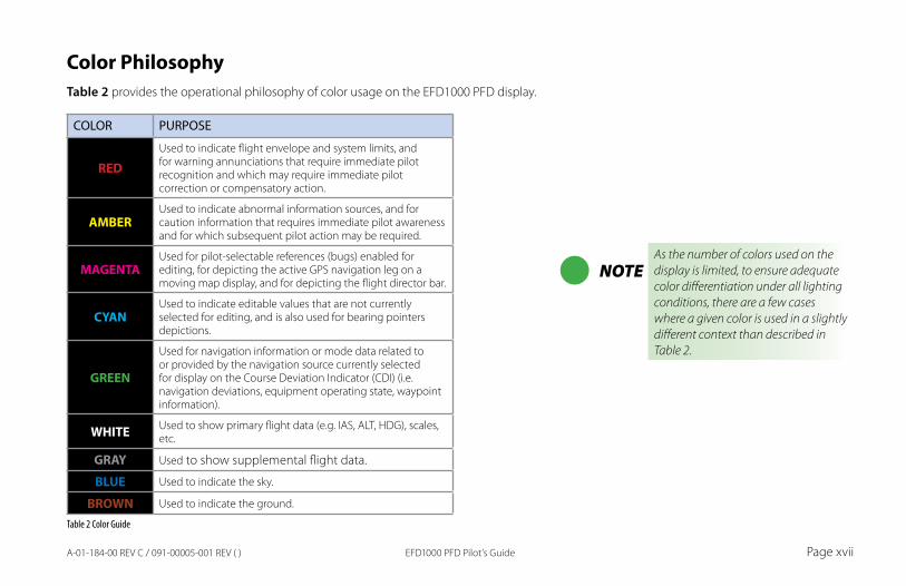
Color PhilosophyTable 2 provides the operational philosophy of color usage on the EFD1000 PFD display.
COLOR PURPOSE
REDUsed to indicate flight envelope and system limits, and for warning annunciations that require immediate pilot recognition and which may require immediate pilot correction or compensatory action.
AMBERUsed to indicate abnormal information sources, and for caution information that requires immediate pilot awareness and for which subsequent pilot action may be required.
MAGENTAUsed for pilot-selectable references (bugs) enabled for editing, for depicting the active GPS navigation leg on a moving map display, and for depicting the flight director bar.
CYANUsed to indicate editable values that are not currently selected for editing, and is also used for bearing pointers depictions.
GREEN
Used for navigation information or mode data related to or provided by the navigation source currently selected for display on the Course Deviation Indicator (CDI) (i.e. navigation deviations, equipment operating state, waypoint information).
WHITE Used to show primary flight data (e.g. IAS, ALT, HDG), scales, etc.
GRAY Used to show supplemental flight data.
BLUE Used to indicate the sky.
BROWN Used to indicate the ground.
Table 2 Color Guide
NOTEAs the number of colors used on the display is limited, to ensure adequate color differentiation under all lighting conditions, there are a few cases where a given color is used in a slightly different context than described in Table 2.
EFD1000 PFD Pilot’s GuidePage xviii A-01-184-00 REV C / 091-00005-001 REV ( )
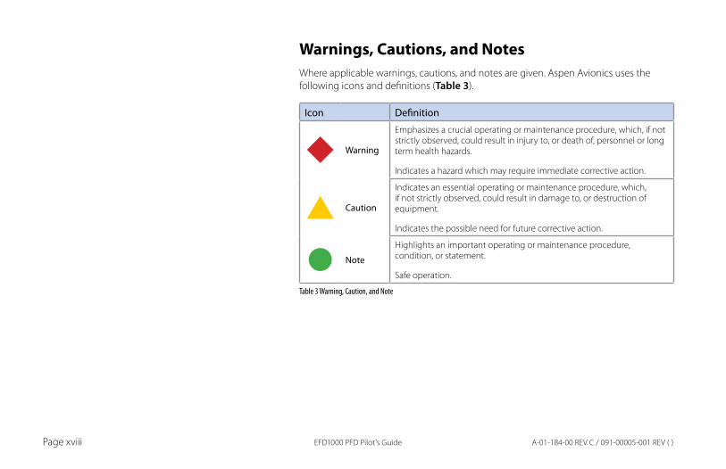
Warnings, Cautions, and NotesWhere applicable warnings, cautions, and notes are given. Aspen Avionics uses the following icons and definitions (Table 3).
Icon Definition
Warning
Emphasizes a crucial operating or maintenance procedure, which, if not strictly observed, could result in injury to, or death of, personnel or long term health hazards.
Indicates a hazard which may require immediate corrective action.
Caution
Indicates an essential operating or maintenance procedure, which, if not strictly observed, could result in damage to, or destruction of equipment.
Indicates the possible need for future corrective action.
Note
Highlights an important operating or maintenance procedure, condition, or statement.
Safe operation.
Table 3 Warning, Caution, and Note
EFD1000 PFD Pilot’s Guide Page xixA-01-184-00 REV C / 091-00005-001 REV ( )
Example GraphicsMost of the example graphics and screen shots used throughout this Pilot’s Guide & Reference are based on flying the ILS 16R instrument approach into Reno/Tahoe International Airport (KRNO) in Reno, Nevada, USA. Those images with the airplane in a right bank show the airplane completing the procedure turn in-bound to intercept the Localizer, descending through 8,660 feet to the target altitude of 8,500 feet. The other main group of images, showing the airplane straight and level, are earlier in the approach, tracking outbound for the procedure turn.
Pilot FamiliarityWhile the EFD1000 is reasonably intuitive and easy to use, some familiarity with Electronic Flight Instrument Systems (EFIS) and Horizontal Situation Indicators (HSI) is required. Aspen Avionics strongly recommends that new users of the EFD1000 get some dual instruction from an experienced instrument CFI, and spend some time becoming familiar with the PFD in day VFR conditions with a safety pilot, before flying in actual instrument meteorological conditions (IMC). To reduce pilot workload, the use of autopilot (when available) is strongly encouraged.

EFD1000 PFD Pilot’s GuidePage xx A-01-184-00 REV C / 091-00005-001 REV ( )
CHA
PTER 1, W
ELCOM
E
EFD1000 PFD Pilot’s Guide Page 1-1A-01-184-00 REV C / 091-00005-001 REV ( )
Chapter 1Welcome & Introduction
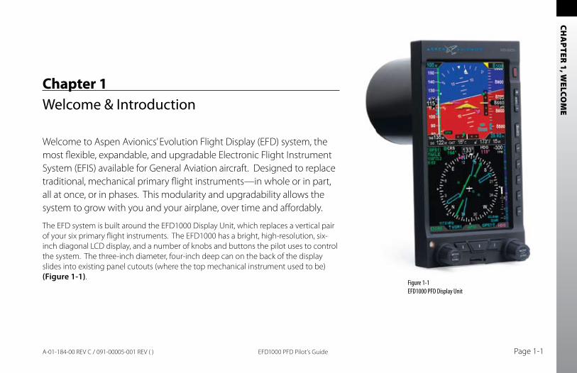
Welcome to Aspen Avionics’ Evolution Flight Display (EFD) system, the most flexible, expandable, and upgradable Electronic Flight Instrument System (EFIS) available for General Aviation aircraft. Designed to replace traditional, mechanical primary flight instruments—in whole or in part, all at once, or in phases. This modularity and upgradability allows the system to grow with you and your airplane, over time and affordably.
The EFD system is built around the EFD1000 Display Unit, which replaces a vertical pair of your six primary flight instruments. The EFD1000 has a bright, high-resolution, six-inch diagonal LCD display, and a number of knobs and buttons the pilot uses to control the system. The three-inch diameter, four-inch deep can on the back of the display slides into existing panel cutouts (where the top mechanical instrument used to be) (Figure 1-1).
Figure 1-1EFD1000 PFD Display Unit
CHA
PTER
1, W
ELCO
ME
EFD1000 PFD Pilot’s GuidePage 1-2 A-01-184-00 REV C / 091-00005-001 REV ( )
Figure 1-3 Two-tube system: PFD & MFD
Figure 1-2 Single-tube EFD1000 PFD system
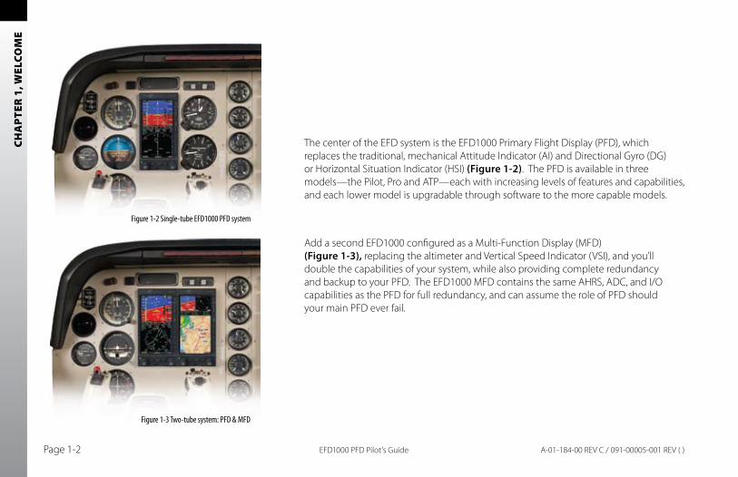
The center of the EFD system is the EFD1000 Primary Flight Display (PFD), which replaces the traditional, mechanical Attitude Indicator (AI) and Directional Gyro (DG) or Horizontal Situation Indicator (HSI) (Figure 1-2). The PFD is available in three models—the Pilot, Pro and ATP—each with increasing levels of features and capabilities, and each lower model is upgradable through software to the more capable models.
Add a second EFD1000 configured as a Multi-Function Display (MFD) (Figure 1-3), replacing the altimeter and Vertical Speed Indicator (VSI), and you’ll double the capabilities of your system, while also providing complete redundancy and backup to your PFD. The EFD1000 MFD contains the same AHRS, ADC, and I/O capabilities as the PFD for full redundancy, and can assume the role of PFD should your main PFD ever fail.
CHA
PTER 1, W
ELCOM
E
EFD1000 PFD Pilot’s Guide Page 1-3A-01-184-00 REV C / 091-00005-001 REV ( )
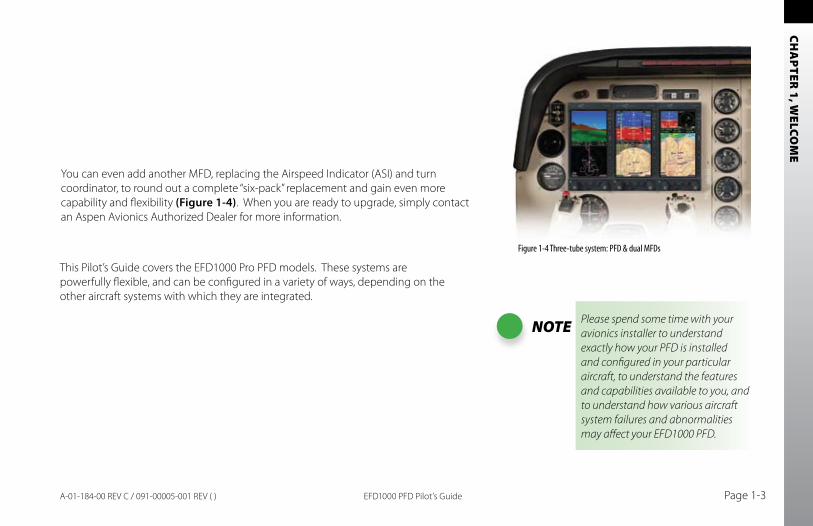
NOTE Please spend some time with your avionics installer to understand exactly how your PFD is installed and configured in your particular aircraft, to understand the features and capabilities available to you, and to understand how various aircraft system failures and abnormalities may affect your EFD1000 PFD.
You can even add another MFD, replacing the Airspeed Indicator (ASI) and turn coordinator, to round out a complete “six-pack” replacement and gain even more capability and flexibility (Figure 1-4). When you are ready to upgrade, simply contact an Aspen Avionics Authorized Dealer for more information.
This Pilot’s Guide covers the EFD1000 Pro PFD models. These systems are powerfully flexible, and can be configured in a variety of ways, depending on the other aircraft systems with which they are integrated.
Figure 1-4 Three-tube system: PFD & dual MFDs
CHA
PTER
1, W
ELCO
ME
EFD1000 PFD Pilot’s GuidePage 1-4 A-01-184-00 REV C / 091-00005-001 REV ( )
Digital GPS/VLOC
Analog GPS/VLOC via ACU
EFD1000 PFD(Primary Flight Display)
Analog Converter Unit
(ACU)
Aircraft Power
Configuration Module
Optional Tone Generator
12C
SPI
RS-232
Digital VLOC/GPSSources
Analog NAV Sources
Radar Altimeter
Autopilot
Legacy GPSRS-232
Discrete
Pitot Static
Existing AircraftStatic Line
Existing AircraftPitot Line
Remote SensorModule(RSM)
ARINC 429
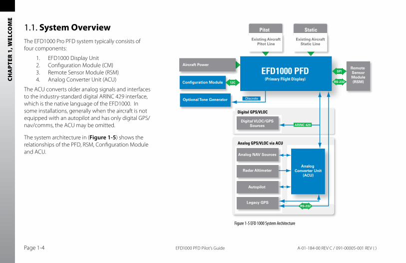
Figure 1-5 EFD 1000 System Architecture
1.1. System OverviewThe EFD1000 Pro PFD system typically consists of four components:
1. EFD1000 Display Unit2. Configuration Module (CM)3. Remote Sensor Module (RSM)4. Analog Converter Unit (ACU)
The ACU converts older analog signals and interfaces to the industry-standard digital ARINC 429 interface, which is the native language of the EFD1000. In some installations, generally when the aircraft is not equipped with an autopilot and has only digital GPS/nav/comms, the ACU may be omitted.
The system architecture in (Figure 1-5) shows the relationships of the PFD, RSM, Configuration Module and ACU.
CHA
PTER 1, W
ELCOM
E
EFD1000 PFD Pilot’s Guide Page 1-5A-01-184-00 REV C / 091-00005-001 REV ( )
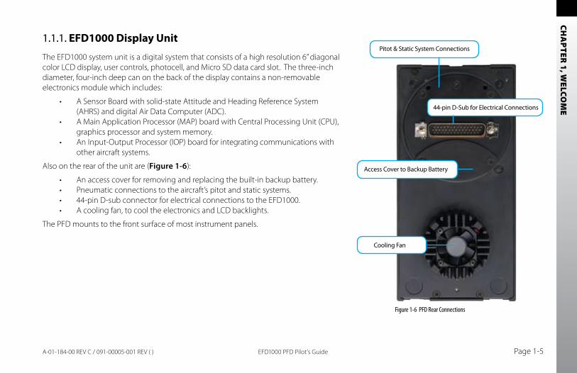
1.1.1. EFD1000 Display Unit
The EFD1000 system unit is a digital system that consists of a high resolution 6” diagonal color LCD display, user controls, photocell, and Micro SD data card slot. The three-inch diameter, four-inch deep can on the back of the display contains a non-removable electronics module which includes:
A Sensor Board with solid-state Attitude and Heading Reference System •(AHRS) and digital Air Data Computer (ADC).A Main Application Processor (MAP) board with Central Processing Unit (CPU), •graphics processor and system memory.An Input-Output Processor (IOP) board for integrating communications with •other aircraft systems.
Also on the rear of the unit are (Figure 1-6):
An access cover for removing and replacing the built-in backup battery.•Pneumatic connections to the aircraft’s pitot and static systems.•44-pin D-sub connector for electrical connections to the EFD1000.•A cooling fan, to cool the electronics and LCD backlights.•
The PFD mounts to the front surface of most instrument panels.
Figure 1-6 PFD Rear Connections
44-pin D-Sub for Electrical Connections
Access Cover to Backup Battery
Pitot & Static System Connections
Cooling Fan
CHA
PTER
1, W
ELCO
ME
EFD1000 PFD Pilot’s GuidePage 1-6 A-01-184-00 REV C / 091-00005-001 REV ( )
1.1.2. Configuration Module (CM)
The Configuration Module contains an EEPROM device that retains system configuration and calibration data and provides two primary functions:
Retains aircraft-specific configuration information, calibration data, and user •settings, allowing the PFD to be swapped for service purposes without re-entering or re-calibrating the installation.Contains a license key that configures the PFD software features.•
The CM is typically attached to the wire bundle coming out of the D-sub connector on the system unit.
1.1.3. Remote Sensor Module (RSM)
The Remote Sensor Module (RSM) is an integral part of the EFD1000 system, and works together with the display unit sensors as part of the AHRS and ADC. The RSM looks and mounts like a GPS antenna, and is mounted on the exterior of the fuselage, typically aft of the cabin.
The RSM contains the following sub-systems:
3D magnetic flux (heading) sensors.•Orientation accelerometers.•Outside Air Temperature (OAT) sensor.•Emergency backup GPS engine and antenna.•
The RSM communicates with the EFD1000 system unit via a digital cable connection.
CHA
PTER 1, W
ELCOM
E
EFD1000 PFD Pilot’s Guide Page 1-7A-01-184-00 REV C / 091-00005-001 REV ( )
1.1.4. Analog Converter Unit (ACU)
The Analog Converter Unit (ACU), included with most Pro PFD systems, enables the all-digital EFD1000 system to interface to analog avionics when required. The ACU converts multiple analog interfaces to the digital ARINC 429 buses supported by the PFD. Control parameters, such as desired heading, are also sent from the PFD to the ACU for conversion to analog format for autopilot support. The ACU is required when any of the following capabilities are required in a Pro PFD installation:
Interface to supported autopilots.•Interface to conventional VHF navigation radios.•Interface to legacy (non-ARINC 429) GPS navigators.•Interface to supported radar altimeter decision height annunciations.•
If ARINC 429-based digital radios, such as the Garmin 400/500-series GPS/nav/comm radios, are installed in the aircraft, and no other aircraft interfaces are desired, the ACU is not required.y

CHA
PTER
1, W
ELCO
ME
EFD1000 PFD Pilot’s GuidePage 1-8 A-01-184-00 REV C / 091-00005-001 REV ( )
CHA
PTER 2, CO
NTR
OLS A
ND
DISPLAY
EFD1000 PFD Pilot’s Guide Page 2-1A-01-184-00 REV C / 091-00005-001 REV ( )
Chapter 2Controls and Display
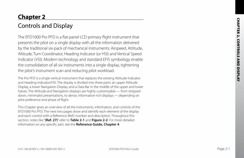
The EFD1000 Pro PFD is a flat-panel LCD primary flight instrument that presents the pilot on a single display with all the information delivered by the traditional six-pack of mechanical instruments: Airspeed, Attitude, Altitude, Turn Coordinator, Heading Indicator (or HSI) and Vertical Speed Indicator (VSI). Modern technology and standard EFIS symbology enable the consolidation of all six instruments into a single display, tightening the pilot’s instrument scan and reducing pilot workload.
The Pro PFD is a single vertical instrument that replaces the existing Attitude Indicator and Heading Indicator/HSI. The display is divided into three parts: an upper Attitude Display, a lower Navigation Display, and a Data Bar in the middle of the upper and lower halves. The Attitude and Navigation displays are highly customizable — from stripped-down, minimalist presentations, to dense, information-rich displays — depending on pilot preference and phase of flight.
This Chapter gives an overview of all the instruments, information, and controls of the EFD1000 Pro PFD. The next two pages show and identify each element of the display and each control with a Reference (Ref.) number and description. Throughout this section, notes like “(Ref. 27)” refer to Table 2-1 and Figure 2-2. For more detailed information on any specific part, see the Reference Guide, Chapter 4.
CHA
PTER
2, C
ON
TRO
LS A
ND
DIS
PLAY
EFD1000 PFD Pilot’s GuidePage 2-2 A-01-184-00 REV C / 091-00005-001 REV ( )
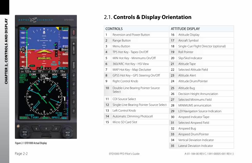
2.1. Controls & Display Orientation
ATTITUDE DISPLAY
16 Attitude Display
17 Aircraft Symbol
18 Single-Cue Flight Director (optional)
19 Roll Pointer
20 Slip/Skid Indicator
21 Altitude Tape
22 Selected Altitude Field
23 Altitude Alert
24 Altitude Drum/Pointer
25 Altitude Bug
26 Decision Height Annunciation
27 Selected Minimums Field
28 MINIMUMS annunication
29 LDI Navigation Source Indication
30 Airspeed Indicator Tape
31 Selected Airspeed Field
32 Airspeed Bug
33 Airspeed Drum/Pointer
34 Vertical Deviation Indicator
35 Lateral Deviation IndicatorFigure 2-1 EFD1000 Actual Display
CONTROLS
1 Reversion and Power Button
2 Range Button
3 Menu Button
4 TPS Hot Key - Tapes On/Off
5 MIN Hot Key - Minimums On/Off
6 360/ARC Hot Key - HSI View
7 MAP Hot Key - Map Declutter
8 GPSS Hot Key - GPS Steering On/Off
9 Right Control Knob
10 Double-Line Bearing Pointer Source Select
11 CDI Source Select
12 Single-Line Bearing Pointer Source Select
13 Left Control Knob
14 Automatic Dimming Photocell
15 Micro SD Card Slot
CHA
PTER 2, CO
NTR
OLS A
ND
DISPLAY
EFD1000 PFD Pilot’s Guide Page 2-3A-01-184-00 REV C / 091-00005-001 REV ( )
1
2
3
4
66 5
6
7
8
91312 11 10
15
14
31 22
30
3318
16
1920
21
17
2834
29
23
32
24
35
2527
26
4136
38394037
64 57
58
6349 48
42
59
51
474446
43
53
52
56
45
50 54
55
61
6062 65
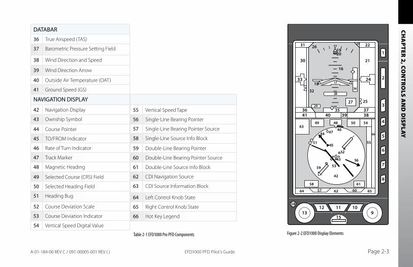
DATABAR
36 True Airspeed (TAS)
37 Barometric Pressure Setting Field
38 Wind Direction and Speed
39 Wind Direction Arrow
40 Outside Air Temperature (OAT)
41 Ground Speed (GS)
NAVIGATION DISPLAY
42 Navigation Display
43 Ownship Symbol
44 Course Pointer
45 TO/FROM Indicator
46 Rate of Turn Indicator
47 Track Marker
48 Magnetic Heading
49 Selected Course (CRS) Field
50 Selected Heading Field
51 Heading Bug
52 Course Deviation Scale
53 Course Deviation Indicator
54 Vertical Speed Digital ValueFigure 2-2 EFD1000 Display ElementsTable 2-1 EFD1000 Pro PFD Components
55 Vertical Speed Tape
56 Single-Line Bearing Pointer
57 Single-Line Bearing Pointer Source
58 Single-Line Source Info Block
59 Double-Line Bearing Pointer
60 Double-Line Bearing Pointer Source
61 Double-Line Source Info Block
62 CDI Navigation Source
63 CDI Source Information Block
64 Left Control Knob State
65 Right Control Knob State
66 Hot Key Legend
CHA
PTER
2, C
ON
TRO
LS A
ND
DIS
PLAY
EFD1000 PFD Pilot’s GuidePage 2-4 A-01-184-00 REV C / 091-00005-001 REV ( )
2.2. ControlsThe primary means for the pilot to control the EFD1000 are the two knobs and three buttons at the bottom of the display. The knobs control setting CRS and HDG, and additional bugs and altitude settings. The three buttons control selection of navigation sources for the CDI and bearing pointers.
Additionally, five hot keys to the right of the Navigation Display toggle various features on and off. The function of each is indicated by the label on the screen to the left of each button. Three additional buttons above the hot keys control entering and exiting the Menu system, setting the Map range, and reversion or manual power control.
2.2.1. Left and Right Knobs
The Left and Right Knobs are both of the push and rotate type. Pressing the knob activates it for control, and subsequent presses cycle through its available control functions in round-robin sequence.
Each knob has an inactive Home state, to which it returns automatically after 10 seconds of inactivity. The inactive state is designed to prevent inadvertent adjustment of a setting. The Left Knob Home state is CRS, and the Right Knob Home state is HDG. A single push of the knob activates the Home state (CRS or HDG) for editing.
To change an available setting, repeatedly press the appropriate knob until the desired function appears in magenta above the knob (the setting you are changing will also appear in magenta on the display). With a little practice, you’ll soon know exactly how many presses it takes from the Home state to get to what you want to set.
CHA
PTER 2, CO
NTR
OLS A
ND
DISPLAY
EFD1000 PFD Pilot’s Guide Page 2-5A-01-184-00 REV C / 091-00005-001 REV ( )
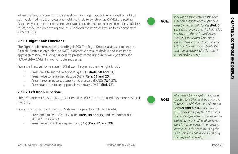
When the function you want to set is shown in magenta, dial the knob left or right to set the desired value, or press and hold the knob to synchronize (SYNC) the setting. Once set, you can either press the knob again to advance to the next function you’d like to set, or you can do nothing and in 10 seconds the knob will return to its home state (CRS or HDG).
2.2.1.1. Right Knob FunctionsThe Right Knob Home state is Heading (HDG). The Right Knob is also used to set the Altitude Alerter seleted altitude (ALT), barometric pressure (BARO) and instrument approach minimums (MIN). Successive presses of the right knob will cycle through HDG-ALT-BARO-MIN in round-robin sequence.
From the inactive Home state (HDG shown in cyan above the right knob):
Press once to set the heading bug (HDG) (• Refs. 50 and 51).Press twice to set target altitude (ALT) (• Refs. 22 and 25).Press three times to set barometric pressure (BARO) (• Ref. 37).Press four times to set approach minimums (MIN) (• Ref. 27).
2.2.1.2. Left Knob FunctionsThe Left Knob Home State is Course (CRS). The Left Knob is also used to set the Airspeed Bug (IAS).
From the inactive Home state (CRS shown in cyan above the left knob):
Press once to set the course (CRS) (• Refs. 44 and 49, and see note at right about Auto Course).Press twice to set the airspeed bug (IAS) (• Refs. 31 and 32).
NOTEMIN will only be shown if the MIN function is already active (the MIN label by the second Hot Key (Ref. 5) is shown in green, and the MIN value is shown on the Attitude Display (Ref. 27). If the MIN function is inactive (label in gray), pressing the MIN Hot Key will both activate the function and immediately make it available for setting.
NOTEWhen the CDI navigation source is selected to a GPS receiver, and Auto Course is enabled in the main menu (see Section 4.3.6), the course is set automatically by the GPS and is not pilot-adjustable. This case will be indicated by the CRS field and Knob label being shown in Green with an inverse “A”. In this case, pressing the Left Knob will enable you to set only the airspeed bug (IAS).
CHA
PTER
2, C
ON
TRO
LS A
ND
DIS
PLAY
EFD1000 PFD Pilot’s GuidePage 2-6 A-01-184-00 REV C / 091-00005-001 REV ( )
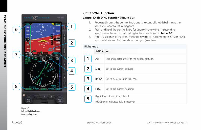
2.2.1.3. SYNC FunctionControl Knob SYNC Function (Figure 2-3)
1. Repeatedly press the control knob until the control knob label shows the value you want to set in magenta.
2. Press and hold the control knob for approximately one (1) second to synchronize the setting according to the rules shown in Table 2-2.
3. After 10 seconds of inaction, the knob reverts to its Home state (CRS or HDG), and the labels and field are shown in cyan (inactive).
Right Knob
SYNC Action
ALT Bug and alerter are set to the current altitude.
MIN Set to the current altitude.
BARO Set to 29.92 InHg or 1013 mB.
HDG Set to the current heading.
Right Knob - Current Field Label
[HDG] (cyan indicates field is inactive)
Figure 2-3Left and Right Knobs and Corresponding Fields
CHA
PTER 2, CO
NTR
OLS A
ND
DISPLAY
EFD1000 PFD Pilot’s Guide Page 2-7A-01-184-00 REV C / 091-00005-001 REV ( )
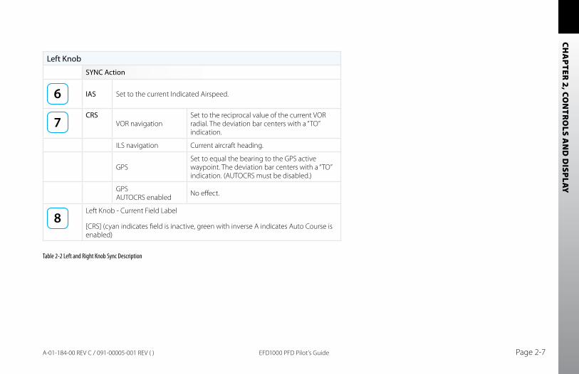
Left Knob
SYNC Action
IAS Set to the current Indicated Airspeed.
CRSVOR navigation
Set to the reciprocal value of the current VOR radial. The deviation bar centers with a “TO” indication.
ILS navigation Current aircraft heading.
GPSSet to equal the bearing to the GPS active waypoint. The deviation bar centers with a “TO” indication. (AUTOCRS must be disabled.)
GPS AUTOCRS enabled No effect.
Left Knob - Current Field Label
[CRS] (cyan indicates field is inactive, green with inverse A indicates Auto Course is enabled)
Table 2-2 Left and Right Knob Sync Description
CHA
PTER
2, C
ON
TRO
LS A
ND
DIS
PLAY
EFD1000 PFD Pilot’s GuidePage 2-8 A-01-184-00 REV C / 091-00005-001 REV ( )
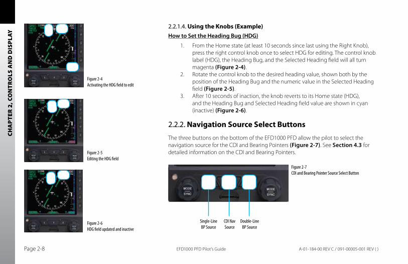
2.2.1.4. Using the Knobs (Example)How to Set the Heading bug (HDG)
1. From the Home state (at least 10 seconds since last using the Right Knob), press the right control knob once to select HDG for editing. The control knob label (HDG), the Heading Bug, and the Selected Heading field will all turn magenta (Figure 2-4).
2. Rotate the control knob to the desired heading value, shown both by the position of the Heading Bug and the numeric value in the Selected Heading field (Figure 2-5).
3. After 10 seconds of inaction, the knob reverts to its Home state (HDG), and the Heading Bug and Selected Heading field value are shown in cyan (inactive) (Figure 2-6).
2.2.2. Navigation Source Select Buttons
The three buttons on the bottom of the EFD1000 PFD allow the pilot to select the navigation source for the CDI and Bearing Pointers (Figure 2-7). See Section 4.3 for detailed information on the CDI and Bearing Pointers.
Figure 2-4 Activating the HDG field to edit
Figure 2-5Editing the HDG field
Figure 2-6 HDG field updated and inactive
Figure 2-7 CDI and Bearing Pointer Source Select Button
Single-Line BP Source
CDI Nav Source
Double-Line BP Source
CHA
PTER 2, CO
NTR
OLS A
ND
DISPLAY
EFD1000 PFD Pilot’s Guide Page 2-9A-01-184-00 REV C / 091-00005-001 REV ( )
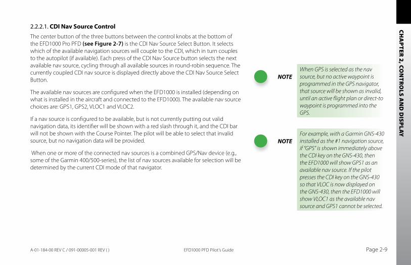
2.2.2.1. CDI Nav Source ControlThe center button of the three buttons between the control knobs at the bottom of the EFD1000 Pro PFD (see Figure 2-7) is the CDI Nav Source Select Button. It selects which of the available navigation sources will couple to the CDI, which in turn couples to the autopilot (if available). Each press of the CDI Nav Source button selects the next available nav source, cycling through all available sources in round-robin sequence. The currently coupled CDI nav source is displayed directly above the CDI Nav Source Select Button.
The available nav sources are configured when the EFD1000 is installed (depending on what is installed in the aircraft and connected to the EFD1000). The available nav source choices are: GPS1, GPS2, VLOC1 and VLOC2.
If a nav source is configured to be available, but is not currently putting out valid navigation data, its identifier will be shown with a red slash through it, and the CDI bar will not be shown with the Course Pointer. The pilot will be able to select that invalid source, but no navigation data will be provided.
When one or more of the connected nav sources is a combined GPS/Nav device (e.g., some of the Garmin 400/500-series), the list of nav sources available for selection will be determined by the current CDI mode of that navigator.
NOTEWhen GPS is selected as the nav source, but no active waypoint is programmed in the GPS navigator, that source will be shown as invalid, until an active flight plan or direct-to waypoint is programmed into the GPS.
NOTEFor example, with a Garmin GNS-430 installed as the #1 navigation source, if “GPS” is shown immediately above the CDI key on the GNS-430, then the EFD1000 will show GPS1 as an available nav source. If the pilot presses the CDI key on the GNS-430 so that VLOC is now displayed on the GNS-430, then the EFD1000 will show VLOC1 as the available nav source and GPS1 cannot be selected.
CHA
PTER
2, C
ON
TRO
LS A
ND
DIS
PLAY
EFD1000 PFD Pilot’s GuidePage 2-10 A-01-184-00 REV C / 091-00005-001 REV ( )
2.2.2.2. Bearing Pointer Nav Source ControlThe two outer buttons between the control knobs are the Bearing Pointer Nav Source Select Buttons (see Figure 2-7). The left-hand button controls BRG1 (the single-line bearing pointer) and the right-hand button controls BRG2 (the double-line bearing pointer), and each controls which nav source is coupled to that bearing pointer.
The bearing pointers act like a conventional RMI (Radio Magnetic Indicator): the needle points to the station. Unlike a conventional RMI, EFD1000 bearing pointers can also point to the active waypoint of a GPS navigator, whether that is a VOR, NDB, airport, intersection, or missed approach point.
Each bearing pointer can be coupled to any of the available navigation sources: GPS1, GPS2, VLOC1, or VLOC2 (depending on configuration), or to none. Each press of the Bearing Pointer Nav Source Select Button selects the next available nav source, cycling through all available nav sources and none, in round-robin sequence. The currently coupled nav source is displayed directly above the Select Button; blank indicates that no nav source is selected and the bearing pointer will not be displayed.
If the selected nav source is a valid choice, but no usable nav data is being received (e.g., the VOR station is out of range), the bearing pointer will not be displayed, or the VLOC is tuned to a localizer frequency.
CHA
PTER 2, CO
NTR
OLS A
ND
DISPLAY
EFD1000 PFD Pilot’s Guide Page 2-11A-01-184-00 REV C / 091-00005-001 REV ( )
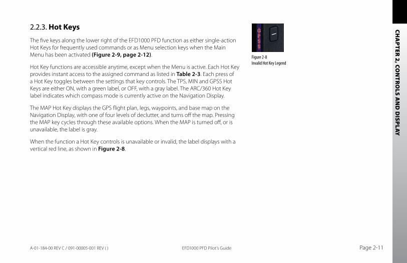
2.2.3. Hot Keys
The five keys along the lower right of the EFD1000 PFD function as either single-action Hot Keys for frequently used commands or as Menu selection keys when the Main Menu has been activated (Figure 2-9, page 2-12).
Hot Key functions are accessible anytime, except when the Menu is active. Each Hot Key provides instant access to the assigned command as listed in Table 2-3. Each press of a Hot Key toggles between the settings that key controls. The TPS, MIN and GPSS Hot Keys are either ON, with a green label, or OFF, with a gray label. The ARC/360 Hot Key label indicates which compass mode is currently active on the Navigation Display.
The MAP Hot Key displays the GPS flight plan, legs, waypoints, and base map on the Navigation Display, with one of four levels of declutter, and turns off the map. Pressing the MAP key cycles through these available options. When the MAP is turned off, or is unavailable, the label is gray.
When the function a Hot Key controls is unavailable or invalid, the label displays with a vertical red line, as shown in Figure 2-8.
Figure 2-8 Invalid Hot Key Legend
CHA
PTER
2, C
ON
TRO
LS A
ND
DIS
PLAY
EFD1000 PFD Pilot’s GuidePage 2-12 A-01-184-00 REV C / 091-00005-001 REV ( )
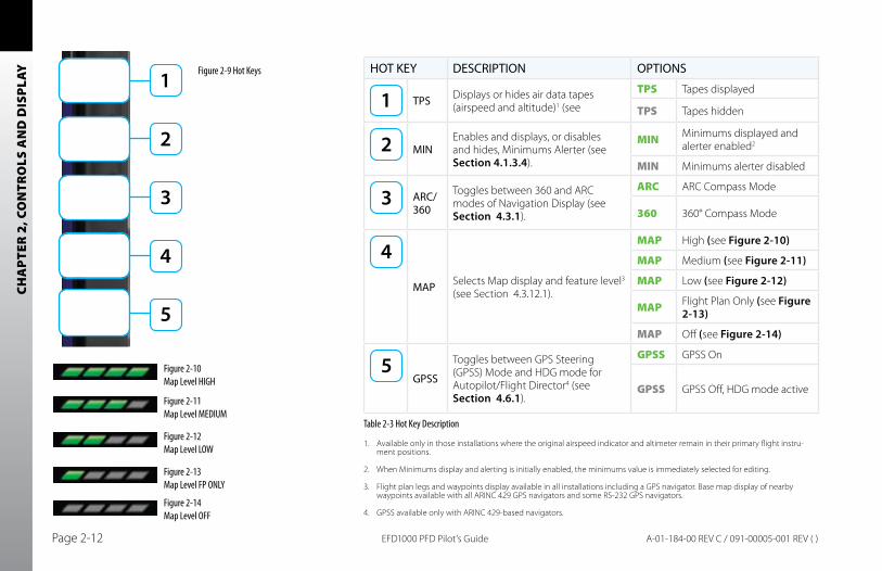
HOT KEY DESCRIPTION OPTIONS
TPS Displays or hides air data tapes (airspeed and altitude)1 (see
TPS Tapes displayed
TPS Tapes hidden
MINEnables and displays, or disables and hides, Minimums Alerter (see Section 4.1.3.4).
MIN Minimums displayed and alerter enabled2
MIN Minimums alerter disabled
ARC/ 360
Toggles between 360 and ARC modes of Navigation Display (see Section 4.3.1).
ARC ARC Compass Mode
360 360° Compass Mode
MAP Selects Map display and feature level3 (see Section 4.3.12.1).
MAP High (see Figure 2-10)
MAP Medium (see Figure 2-11)
MAP Low (see Figure 2-12)
MAP Flight Plan Only (see Figure 2-13)
MAP Off (see Figure 2-14)
GPSS
Toggles between GPS Steering (GPSS) Mode and HDG mode for Autopilot/Flight Director4 (see Section 4.6.1).
GPSS GPSS On
GPSS GPSS Off, HDG mode active
Available only in those installations where the original airspeed indicator and altimeter remain in their primary flight instru-1. ment positions.
When Minimums display and alerting is initially enabled, the minimums value is immediately selected for editing.2.
Flight plan legs and waypoints display available in all installations including a GPS navigator. Base map display of nearby 3. waypoints available with all ARINC 429 GPS navigators and some RS-232 GPS navigators.
GPSS available only with ARINC 429-based navigators.4.
Figure 2-10 Map Level HIGH
Figure 2-11 Map Level MEDIUM
Figure 2-12 Map Level LOW
Figure 2-13 Map Level FP ONLY
Figure 2-14 Map Level OFF
Figure 2-9 Hot Keys
Table 2-3 Hot Key Description
CHA
PTER 2, CO
NTR
OLS A
ND
DISPLAY
EFD1000 PFD Pilot’s Guide Page 2-13A-01-184-00 REV C / 091-00005-001 REV ( )
2.2.4. Menu Key
The MENU Key is used to access the EFD1000 PFD’s Menu system to change options, and also to change the EFD1000’s LCD brightness controls.
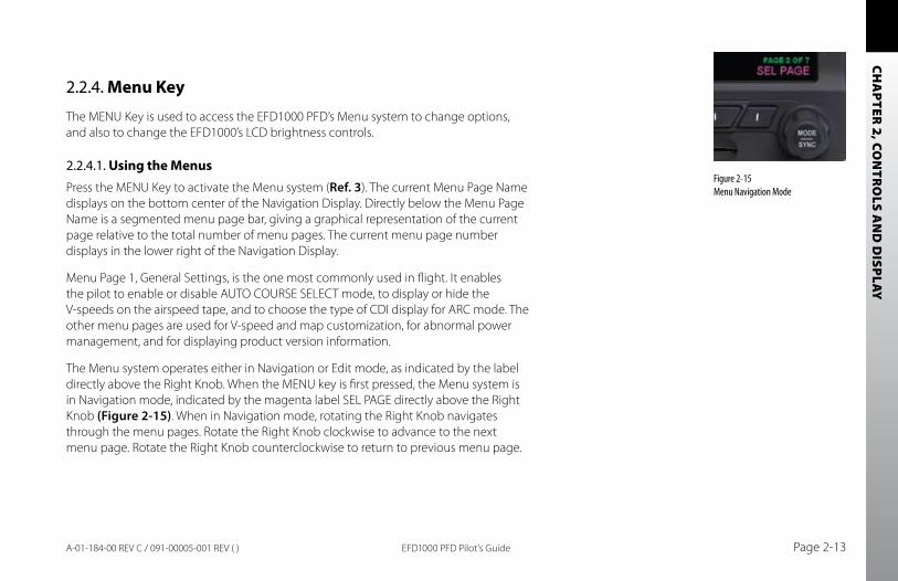
2.2.4.1. Using the MenusPress the MENU Key to activate the Menu system (Ref. 3). The current Menu Page Name displays on the bottom center of the Navigation Display. Directly below the Menu Page Name is a segmented menu page bar, giving a graphical representation of the current page relative to the total number of menu pages. The current menu page number displays in the lower right of the Navigation Display.
Menu Page 1, General Settings, is the one most commonly used in flight. It enables the pilot to enable or disable AUTO COURSE SELECT mode, to display or hide the V-speeds on the airspeed tape, and to choose the type of CDI display for ARC mode. The other menu pages are used for V-speed and map customization, for abnormal power management, and for displaying product version information.
The Menu system operates either in Navigation or Edit mode, as indicated by the label directly above the Right Knob. When the MENU key is first pressed, the Menu system is in Navigation mode, indicated by the magenta label SEL PAGE directly above the Right Knob (Figure 2-15). When in Navigation mode, rotating the Right Knob navigates through the menu pages. Rotate the Right Knob clockwise to advance to the next menu page. Rotate the Right Knob counterclockwise to return to previous menu page.
Figure 2-15 Menu Navigation Mode
CHA
PTER
2, C
ON
TRO
LS A
ND
DIS
PLAY
EFD1000 PFD Pilot’s GuidePage 2-14 A-01-184-00 REV C / 091-00005-001 REV ( )
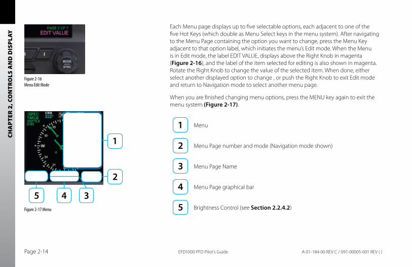
Each Menu page displays up to five selectable options, each adjacent to one of the five Hot Keys (which double as Menu Select keys in the menu system). After navigating to the Menu Page containing the option you want to change, press the Menu Key adjacent to that option label, which initiates the menu’s Edit mode. When the Menu is in Edit mode, the label EDIT VALUE, displays above the Right Knob in magenta (Figure 2-16), and the label of the item selected for editing is also shown in magenta. Rotate the Right Knob to change the value of the selected item. When done, either select another displayed option to change , or push the Right Knob to exit Edit mode and return to Navigation mode to select another menu page.
When you are finished changing menu options, press the MENU key again to exit the menu system (Figure 2-17).
Menu
Menu Page number and mode (Navigation mode shown)
Menu Page Name
Menu Page graphical bar
Brightness Control (see Section 2.2.4.2)
Figure 2-16 Menu Edit Mode
Figure 2-17 Menu
CHA
PTER 2, CO
NTR
OLS A
ND
DISPLAY
EFD1000 PFD Pilot’s Guide Page 2-15A-01-184-00 REV C / 091-00005-001 REV ( )
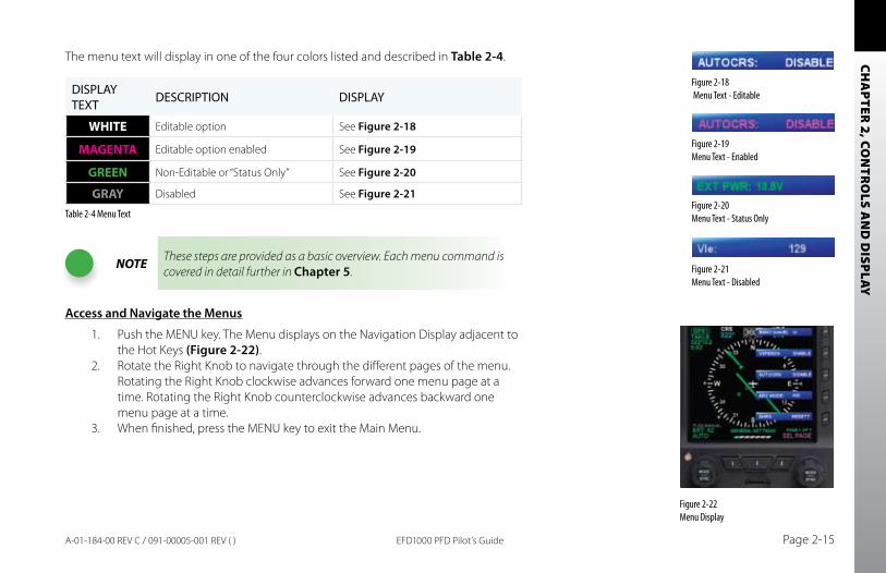
The menu text will display in one of the four colors listed and described in Table 2-4.
DISPLAY TEXT DESCRIPTION DISPLAY
WHITE Editable option See Figure 2-18
MAGENTA Editable option enabled See Figure 2-19
GREEN Non-Editable or “Status Only” See Figure 2-20
GRAY Disabled See Figure 2-21
Table 2-4 Menu Text
NOTE These steps are provided as a basic overview. Each menu command is covered in detail further in Chapter 5.
Access and Navigate the Menus
1. Push the MENU key. The Menu displays on the Navigation Display adjacent to the Hot Keys (Figure 2-22).
2. Rotate the Right Knob to navigate through the different pages of the menu. Rotating the Right Knob clockwise advances forward one menu page at a time. Rotating the Right Knob counterclockwise advances backward one menu page at a time.
3. When finished, press the MENU key to exit the Main Menu.
Figure 2-22 Menu Display
Figure 2-18 Menu Text - Editable
Figure 2-19 Menu Text - Enabled
Figure 2-20 Menu Text - Status Only
Figure 2-21 Menu Text - Disabled
CHA
PTER
2, C
ON
TRO
LS A
ND
DIS
PLAY
EFD1000 PFD Pilot’s GuidePage 2-16 A-01-184-00 REV C / 091-00005-001 REV ( )
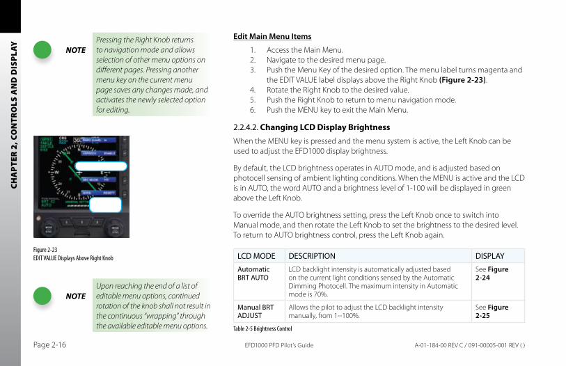
Edit Main Menu Items
1. Access the Main Menu.2. Navigate to the desired menu page.3. Push the Menu Key of the desired option. The menu label turns magenta and
the EDIT VALUE label displays above the Right Knob (Figure 2-23).4. Rotate the Right Knob to the desired value.5. Push the Right Knob to return to menu navigation mode.6. Push the MENU key to exit the Main Menu.
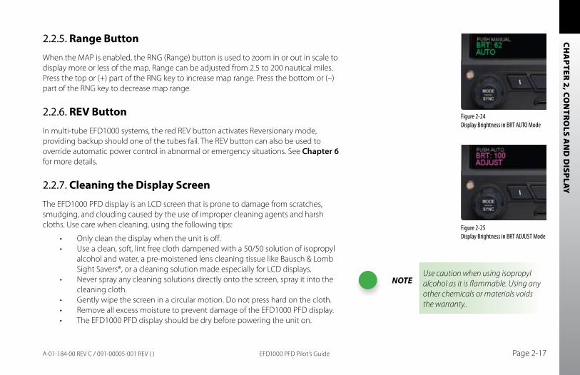
2.2.4.2. Changing LCD Display BrightnessWhen the MENU key is pressed and the menu system is active, the Left Knob can be used to adjust the EFD1000 display brightness.
By default, the LCD brightness operates in AUTO mode, and is adjusted based on photocell sensing of ambient lighting conditions. When the MENU is active and the LCD is in AUTO, the word AUTO and a brightness level of 1-100 will be displayed in green above the Left Knob.
To override the AUTO brightness setting, press the Left Knob once to switch into Manual mode, and then rotate the Left Knob to set the brightness to the desired level. To return to AUTO brightness control, press the Left Knob again.
LCD MODE DESCRIPTION DISPLAY
Automatic BRT AUTO
LCD backlight intensity is automatically adjusted based on the current light conditions sensed by the Automatic Dimming Photocell. The maximum intensity in Automatic mode is 70%.
See Figure 2-24
Manual BRT ADJUST
Allows the pilot to adjust the LCD backlight intensity manually, from 1--100%.
See Figure 2-25
Table 2-5 Brightness Control
Figure 2-23 EDIT VALUE Displays Above Right Knob
NOTEUpon reaching the end of a list of editable menu options, continued rotation of the knob shall not result in the continuous “wrapping” through the available editable menu options.
NOTEPressing the Right Knob returns to navigation mode and allows selection of other menu options on different pages. Pressing another menu key on the current menu page saves any changes made, and activates the newly selected option for editing.
CHA
PTER 2, CO
NTR
OLS A
ND
DISPLAY
EFD1000 PFD Pilot’s Guide Page 2-17A-01-184-00 REV C / 091-00005-001 REV ( )
2.2.5. Range Button
When the MAP is enabled, the RNG (Range) button is used to zoom in or out in scale to display more or less of the map. Range can be adjusted from 2.5 to 200 nautical miles. Press the top or (+) part of the RNG key to increase map range. Press the bottom or (–) part of the RNG key to decrease map range.
2.2.6. REV Button
In multi-tube EFD1000 systems, the red REV button activates Reversionary mode, providing backup should one of the tubes fail. The REV button can also be used to override automatic power control in abnormal or emergency situations. See Chapter 6 for more details.
2.2.7. Cleaning the Display Screen
The EFD1000 PFD display is an LCD screen that is prone to damage from scratches, smudging, and clouding caused by the use of improper cleaning agents and harsh cloths. Use care when cleaning, using the following tips:
Only clean the display when the unit is off.•Use a clean, soft, lint free cloth dampened with a 50/50 solution of isopropyl •alcohol and water, a pre-moistened lens cleaning tissue like Bausch & Lomb Sight Savers®, or a cleaning solution made especially for LCD displays.Never spray any cleaning solutions directly onto the screen, spray it into the •cleaning cloth.Gently wipe the screen in a circular motion. Do not press hard on the cloth. •Remove all excess moisture to prevent damage of the EFD1000 PFD display.•The EFD1000 PFD display should be dry before powering the unit on.•
Figure 2-24 Display Brightness in BRT AUTO Mode
Figure 2-25 Display Brightness in BRT ADJUST Mode
NOTEUse caution when using isopropyl alcohol as it is flammable. Using any other chemicals or materials voids the warranty..
CHA
PTER
2, C
ON
TRO
LS A
ND
DIS
PLAY
EFD1000 PFD Pilot’s GuidePage 2-18 A-01-184-00 REV C / 091-00005-001 REV ( )
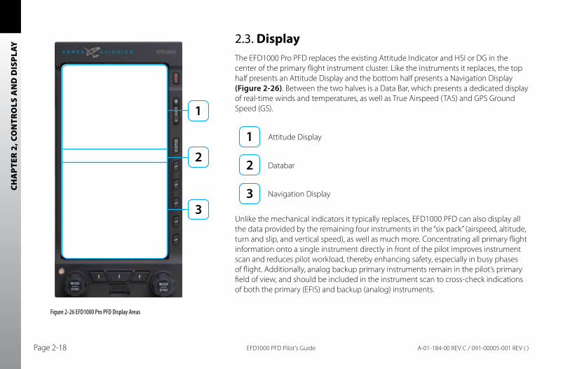
2.3. DisplayThe EFD1000 Pro PFD replaces the existing Attitude Indicator and HSI or DG in the center of the primary flight instrument cluster. Like the instruments it replaces, the top half presents an Attitude Display and the bottom half presents a Navigation Display (Figure 2-26). Between the two halves is a Data Bar, which presents a dedicated display of real-time winds and temperatures, as well as True Airspeed (TAS) and GPS Ground Speed (GS).
Attitude Display
Databar
Navigation Display
Unlike the mechanical indicators it typically replaces, EFD1000 PFD can also display all the data provided by the remaining four instruments in the “six pack” (airspeed, altitude, turn and slip, and vertical speed), as well as much more. Concentrating all primary flight information onto a single instrument directly in front of the pilot improves instrument scan and reduces pilot workload, thereby enhancing safety, especially in busy phases of flight. Additionally, analog backup primary instruments remain in the pilot’s primary field of view, and should be included in the instrument scan to cross-check indications of both the primary (EFIS) and backup (analog) instruments.
Figure 2-26 EFD1000 Pro PFD Display Areas

CHA
PTER 2, CO
NTR
OLS A
ND
DISPLAY
EFD1000 PFD Pilot’s Guide Page 2-19A-01-184-00 REV C / 091-00005-001 REV ( )
The EFD1000 PFD generally follows standard display conventions for Electronic Flight Instrument Systems (EFIS), so a pilot with some experience and familiarity with other EFIS PFDs will usually transition quickly to using the EFD1000. Pilots for whom the EFD1000 PFD is their first real exposure to EFIS and “glass cockpit” flying, however, should get some in-flight transition training from a certified instrument flight instructor (CFII) with EFIS experience. Pilots are also encouraged to study some of the excellent publications now available to help the transition from analog to EFIS instrument flying, including the FAA’s latest versions of the Instrument Flying Handbook.
This section gives an overview of the main display elements and features. For more detail, see the Reference Guide, Chapter 4.
CHA
PTER
2, C
ON
TRO
LS A
ND
DIS
PLAY
EFD1000 PFD Pilot’s GuidePage 2-20 A-01-184-00 REV C / 091-00005-001 REV ( )
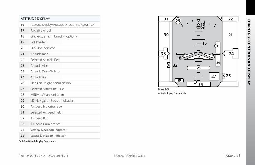
2.3.1. Attitude Display
The Attitude Display includes an Attitude Director Indicator (ADI) with single-cue Flight Director command V-bars (when connected to a compatible autopilot), an Airspeed tape, an Altimeter tape, an Altitude Alerter (with separate minimums alerting), and Instrument Approach indicators (Table 2-6 and Figure 2-27). For more details on each, see the Reference Guide, Chapter 4.
The Airspeed and Altitude tapes are the most obvious differences from a mechanical ADI. These tapes are common on most EFIS PFDs, and will be immediately familiar to pilots with EFIS experience. Pilots without prior EFIS experience may need some time, experience, and training to get comfortable using the Airspeed and Altimeter tapes as their primary references.
In single-tube EFD1000 PFD installations, where the mechanical airspeed indicator and altimeter remain in their original locations, transitioning pilots can use either their familiar mechanical instruments or the PFD tapes for airspeed and altitude references. Many pilots new to EFIS quickly find themselves relying on the tapes within just a flight or two. If the tapes prove distracting at any time, however, the pilot can remove them from the display by pressing the TPS Hot Key (Figure 2-2 No. 66, single-tube installations only).
CHA
PTER 2, CO
NTR
OLS A
ND
DISPLAY
EFD1000 PFD Pilot’s Guide Page 2-21A-01-184-00 REV C / 091-00005-001 REV ( )
ATTITUDE DISPLAY
16 Attitude Display/Attitude Director Indicator (ADI)
17 Aircraft Symbol
18 Single-Cue Flight Director (optional)
19 Roll Pointer
20 Slip/Skid Indicator
21 Altitude Tape
22 Selected Altitude Field
23 Altitude Alert
24 Altitude Drum/Pointer
25 Altitude Bug
26 Decision Height Annunciation
27 Selected Minimums Field
28 MINIMUMS annunication
29 LDI Navigation Source Indication
30 Airspeed Indicator Tape
31 Selected Airspeed Field
32 Airspeed Bug
33 Airspeed Drum/Pointer
34 Vertical Deviation Indicator
35 Lateral Deviation Indicator
Table 2-6 Attitude Display Components
31 22
30
3318
16
1920
21
17
2834
29
23
32
24
35
2527
26
Figure 2-27 Attitude Display Components
CHA
PTER
2, C
ON
TRO
LS A
ND
DIS
PLAY
EFD1000 PFD Pilot’s GuidePage 2-22 A-01-184-00 REV C / 091-00005-001 REV ( )
2.3.1.1. Attitude Director Indicator (ADI)The Attitude Director Indicator (ADI) features a conventional blue (sky) over brown (ground) background, with a white horizon line dividing the two areas. A triangular aircraft reference symbol (Ref. 17) is in a fixed position, and shows aircraft attitude relative to the horizon.
The pitch scale (or ladder) indicates degrees of nose up (blue) or nose down (brown) pitch relative to the apex of the aircraft symbol. Minor pitch marks are shown every 2.5º up to +/-20º of pitch, with major pitch marks every 10º up to +/-90º of pitch. The distance between pitch marks is greater than on most mechanical attitude indicators, making it easier for the pilot to fly more precise pitch attitudes.
At extreme pitch attitudes (above 30º nose up or below 25º nose down), red Unusual Attitude Recovery chevrons appear, pointing towards the horizon. At extreme pitch attitudes, some sky (blue) or ground (brown) will always be displayed to help maintain situational awareness, even though the horizon line may be off-scale.
At the top of the ADI are the roll scale, roll pointer, and slip/skid indicator (Figure 2-28). The roll scale is indicated by tick marks at 10º, 20º, 30º, 45º, and 60º on both sides of the zero roll inverted solid white triangle. The 45º marks are represented as hollow triangles.
Slip/skid is indicated by the lateral position of the white rectangle under the roll pointer. One rectangle width is equivalent to one ball width of a conventional inclinometer.
When connected to a compatible autopilot system the EFD1000 will display a single-cue Flight Director (Figure 2-29). The Flight Director command bars visually represent the lateral and vertical steering cues transmitted to the EFD by the autopilot. When the FD output from the autopilot is unavailable or flagged invalid, the FD command bars are removed from the display.
Figure 2-28Slip/Skid
Figure 2-29Flight Director
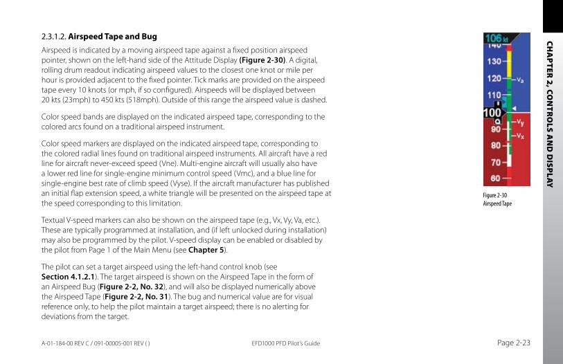
CHA
PTER 2, CO
NTR
OLS A
ND
DISPLAY
EFD1000 PFD Pilot’s Guide Page 2-23A-01-184-00 REV C / 091-00005-001 REV ( )
2.3.1.2. Airspeed Tape and BugAirspeed is indicated by a moving airspeed tape against a fixed position airspeed pointer, shown on the left-hand side of the Attitude Display (Figure 2-30). A digital, rolling drum readout indicating airspeed values to the closest one knot or mile per hour is provided adjacent to the fixed pointer. Tick marks are provided on the airspeed tape every 10 knots (or mph, if so configured). Airspeeds will be displayed between 20 kts (23mph) to 450 kts (518mph). Outside of this range the airspeed value is dashed.
Color speed bands are displayed on the indicated airspeed tape, corresponding to the colored arcs found on a traditional airspeed instrument.
Color speed markers are displayed on the indicated airspeed tape, corresponding to the colored radial lines found on traditional airspeed instruments. All aircraft have a red line for aircraft never-exceed speed (Vne). Multi-engine aircraft will usually also have a lower red line for single-engine minimum control speed (Vmc), and a blue line for single-engine best rate of climb speed (Vyse). If the aircraft manufacturer has published an initial flap extension speed, a white triangle will be presented on the airspeed tape at the speed corresponding to this limitation.
Textual V-speed markers can also be shown on the airspeed tape (e.g., Vx, Vy, Va, etc.). These are typically programmed at installation, and (if left unlocked during installation) may also be programmed by the pilot. V-speed display can be enabled or disabled by the pilot from Page 1 of the Main Menu (see Chapter 5).
The pilot can set a target airspeed using the left-hand control knob (see Section 4.1.2.1). The target airspeed is shown on the Airspeed Tape in the form of an Airspeed Bug (Figure 2-2, No. 32), and will also be displayed numerically above the Airspeed Tape (Figure 2-2, No. 31). The bug and numerical value are for visual reference only, to help the pilot maintain a target airspeed; there is no alerting for deviations from the target.
Figure 2-30Airspeed Tape
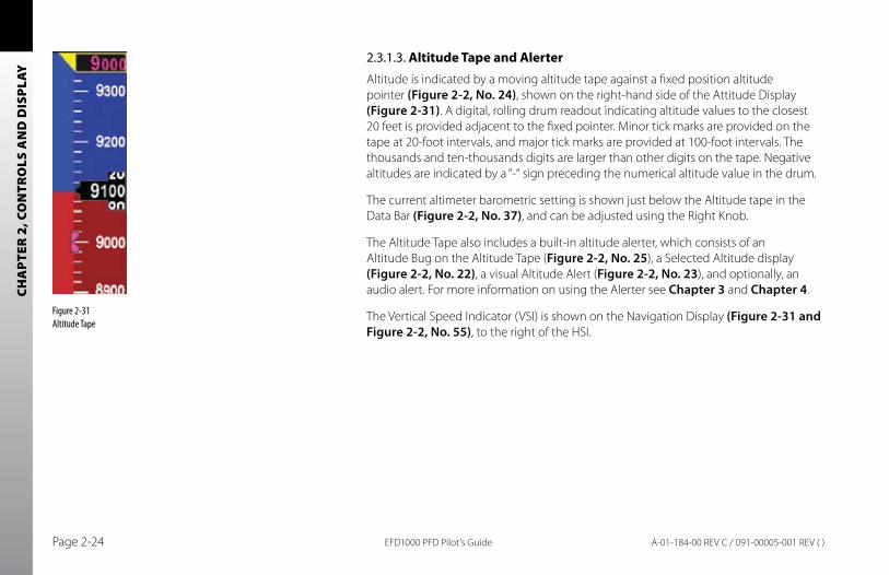
CHA
PTER
2, C
ON
TRO
LS A
ND
DIS
PLAY
EFD1000 PFD Pilot’s GuidePage 2-24 A-01-184-00 REV C / 091-00005-001 REV ( )
2.3.1.3. Altitude Tape and AlerterAltitude is indicated by a moving altitude tape against a fixed position altitude pointer (Figure 2-2, No. 24), shown on the right-hand side of the Attitude Display (Figure 2-31). A digital, rolling drum readout indicating altitude values to the closest 20 feet is provided adjacent to the fixed pointer. Minor tick marks are provided on the tape at 20-foot intervals, and major tick marks are provided at 100-foot intervals. The thousands and ten-thousands digits are larger than other digits on the tape. Negative altitudes are indicated by a “-“ sign preceding the numerical altitude value in the drum.
The current altimeter barometric setting is shown just below the Altitude tape in the Data Bar (Figure 2-2, No. 37), and can be adjusted using the Right Knob.
The Altitude Tape also includes a built-in altitude alerter, which consists of an Altitude Bug on the Altitude Tape (Figure 2-2, No. 25), a Selected Altitude display (Figure 2-2, No. 22), a visual Altitude Alert (Figure 2-2, No. 23), and optionally, an audio alert. For more information on using the Alerter see Chapter 3 and Chapter 4.
The Vertical Speed Indicator (VSI) is shown on the Navigation Display (Figure 2-31 and Figure 2-2, No. 55), to the right of the HSI.
Figure 2-31 Altitude Tape
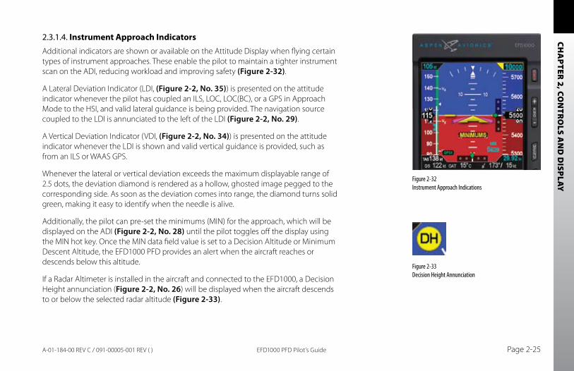
CHA
PTER 2, CO
NTR
OLS A
ND
DISPLAY
EFD1000 PFD Pilot’s Guide Page 2-25A-01-184-00 REV C / 091-00005-001 REV ( )
2.3.1.4. Instrument Approach IndicatorsAdditional indicators are shown or available on the Attitude Display when flying certain types of instrument approaches. These enable the pilot to maintain a tighter instrument scan on the ADI, reducing workload and improving safety (Figure 2-32).
A Lateral Deviation Indicator (LDI, (Figure 2-2, No. 35)) is presented on the attitude indicator whenever the pilot has coupled an ILS, LOC, LOC(BC), or a GPS in Approach Mode to the HSI, and valid lateral guidance is being provided. The navigation source coupled to the LDI is annunciated to the left of the LDI (Figure 2-2, No. 29).
A Vertical Deviation Indicator (VDI, (Figure 2-2, No. 34)) is presented on the attitude indicator whenever the LDI is shown and valid vertical guidance is provided, such as from an ILS or WAAS GPS.
Whenever the lateral or vertical deviation exceeds the maximum displayable range of 2.5 dots, the deviation diamond is rendered as a hollow, ghosted image pegged to the corresponding side. As soon as the deviation comes into range, the diamond turns solid green, making it easy to identify when the needle is alive.
Additionally, the pilot can pre-set the minimums (MIN) for the approach, which will be displayed on the ADI (Figure 2-2, No. 28) until the pilot toggles off the display using the MIN hot key. Once the MIN data field value is set to a Decision Altitude or Minimum Descent Altitude, the EFD1000 PFD provides an alert when the aircraft reaches or descends below this altitude.
If a Radar Altimeter is installed in the aircraft and connected to the EFD1000, a Decision Height annunciation (Figure 2-2, No. 26) will be displayed when the aircraft descends to or below the selected radar altitude (Figure 2-33).
Figure 2-32 Instrument Approach Indications
Figure 2-33 Decision Height Annunciation
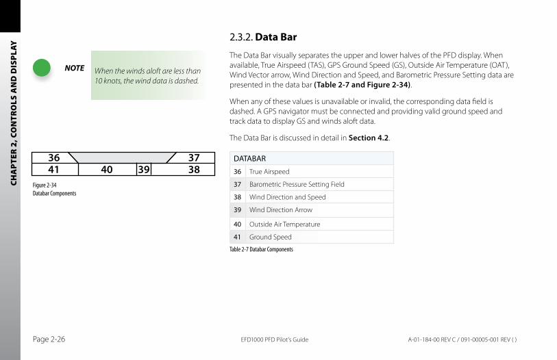
CHA
PTER
2, C
ON
TRO
LS A
ND
DIS
PLAY
EFD1000 PFD Pilot’s GuidePage 2-26 A-01-184-00 REV C / 091-00005-001 REV ( )
2.3.2. Data Bar
The Data Bar visually separates the upper and lower halves of the PFD display. When available, True Airspeed (TAS), GPS Ground Speed (GS), Outside Air Temperature (OAT), Wind Vector arrow, Wind Direction and Speed, and Barometric Pressure Setting data are presented in the data bar (Table 2-7 and Figure 2-34).
When any of these values is unavailable or invalid, the corresponding data field is dashed. A GPS navigator must be connected and providing valid ground speed and track data to display GS and winds aloft data.
The Data Bar is discussed in detail in Section 4.2.
DATABAR
36 True Airspeed
37 Barometric Pressure Setting Field
38 Wind Direction and Speed
39 Wind Direction Arrow
40 Outside Air Temperature
41 Ground Speed
Table 2-7 Databar Components
4136
38394037
Figure 2-34 Databar Components
NOTE When the winds aloft are less than 10 knots, the wind data is dashed.
CHA
PTER 2, CO
NTR
OLS A
ND
DISPLAY
EFD1000 PFD Pilot’s Guide Page 2-27A-01-184-00 REV C / 091-00005-001 REV ( )
2.3.3. Navigation Display
The lower half of the EFD1000 PFD is the Navigation Display, which shows a wide range of navigation information and flight data, including (Figure 2-35):
Horizontal Situation Indicator (HSI), with Course Pointer and Deviation •Indicator (CDI), and Heading Bug, offering both 360º and ARC mode views.Digital readouts of current magnetic heading, selected heading (HDG), and •selected course (CRS).Information about the currently selected navigation source, or active GPS •waypoint.Ground Track indicator.•Vertical Speed Indicator (VSI) tape and digital rate value.•Rate of Turn indicator.•Dual bearing pointers (RMI).•Situational awareness Map display.•Identification of the navigation sources to which the Course Deviation •Indicator (CDI) and two bearing pointers are currently coupled.GPS Annunciations (TERM, APPR, WPT and MSG).•Caution annunciations for abnormal GPS status.•
When connected to a GPS navigator, basic mapping can also be displayed under the HSI display, including GPS flight plan legs and waypoints, and (when connected to a compatible GPS) nearby navigation data (airports, VORs, NDBs and intersections).
NOTEThe Vertical Deviation Indicator (VDI) and Lateral Deviation Indicator (LDI) are part of the navigation instruments but display on the Attitude Display.
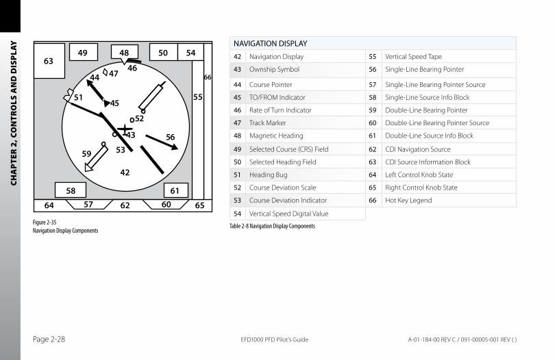
CHA
PTER
2, C
ON
TRO
LS A
ND
DIS
PLAY
EFD1000 PFD Pilot’s GuidePage 2-28 A-01-184-00 REV C / 091-00005-001 REV ( )
NAVIGATION DISPLAY
42 Navigation Display 55 Vertical Speed Tape
43 Ownship Symbol 56 Single-Line Bearing Pointer
44 Course Pointer 57 Single-Line Bearing Pointer Source
45 TO/FROM Indicator 58 Single-Line Source Info Block
46 Rate of Turn Indicator 59 Double-Line Bearing Pointer
47 Track Marker 60 Double-Line Bearing Pointer Source
48 Magnetic Heading 61 Double-Line Source Info Block
49 Selected Course (CRS) Field 62 CDI Navigation Source
50 Selected Heading Field 63 CDI Source Information Block
51 Heading Bug 64 Left Control Knob State
52 Course Deviation Scale 65 Right Control Knob State
53 Course Deviation Indicator 66 Hot Key Legend
54 Vertical Speed Digital Value
Table 2-8 Navigation Display Components
64 5758
6349 48
42
59
51
474446
43
53
52
56
45
50 54
55
66
616062 65
Figure 2-35 Navigation Display Components
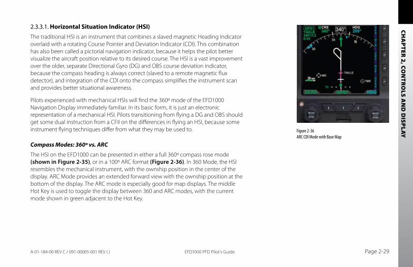
CHA
PTER 2, CO
NTR
OLS A
ND
DISPLAY
EFD1000 PFD Pilot’s Guide Page 2-29A-01-184-00 REV C / 091-00005-001 REV ( )
2.3.3.1. Horizontal Situation Indicator (HSI)The traditional HSI is an instrument that combines a slaved magnetic Heading Indicator overlaid with a rotating Course Pointer and Deviation Indicator (CDI). This combination has also been called a pictorial navigation indicator, because it helps the pilot better visualize the aircraft position relative to its desired course. The HSI is a vast improvement over the older, separate Directional Gyro (DG) and OBS course deviation indicator, because the compass heading is always correct (slaved to a remote magnetic flux detector), and integration of the CDI onto the compass simplifies the instrument scan and provides better situational awareness.
Pilots experienced with mechanical HSIs will find the 360º mode of the EFD1000 Navigation Display immediately familiar. In its basic form, it is just an electronic representation of a mechanical HSI. Pilots transitioning from flying a DG and OBS should get some dual instruction from a CFII on the differences in flying an HSI, because some instrument flying techniques differ from what they may be used to.
Compass Modes: 360º vs. ARC
The HSI on the EFD1000 can be presented in either a full 360º compass rose mode (shown in Figure 2-35), or in a 100º ARC format (Figure 2-36). In 360 Mode, the HSI resembles the mechanical instrument, with the ownship position in the center of the display. ARC Mode provides an extended forward view with the ownship position at the bottom of the display. The ARC mode is especially good for map displays. The middle Hot Key is used to toggle the display between 360 and ARC modes, with the current mode shown in green adjacent to the Hot Key.
Figure 2-36 ARC CDI Mode with Base Map
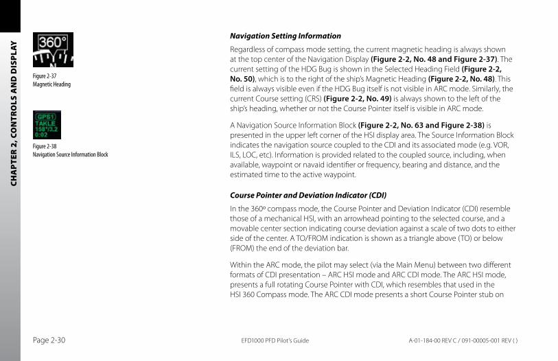
CHA
PTER
2, C
ON
TRO
LS A
ND
DIS
PLAY
EFD1000 PFD Pilot’s GuidePage 2-30 A-01-184-00 REV C / 091-00005-001 REV ( )
Navigation Setting Information
Regardless of compass mode setting, the current magnetic heading is always shown at the top center of the Navigation Display (Figure 2-2, No. 48 and Figure 2-37). The current setting of the HDG Bug is shown in the Selected Heading Field (Figure 2-2, No. 50), which is to the right of the ship’s Magnetic Heading (Figure 2-2, No. 48). This field is always visible even if the HDG Bug itself is not visible in ARC mode. Similarly, the current Course setting (CRS) (Figure 2-2, No. 49) is always shown to the left of the ship’s heading, whether or not the Course Pointer itself is visible in ARC mode.
A Navigation Source Information Block (Figure 2-2, No. 63 and Figure 2-38) is presented in the upper left corner of the HSI display area. The Source Information Block indicates the navigation source coupled to the CDI and its associated mode (e.g. VOR, ILS, LOC, etc). Information is provided related to the coupled source, including, when available, waypoint or navaid identifier or frequency, bearing and distance, and the estimated time to the active waypoint.
Course Pointer and Deviation Indicator (CDI)
In the 360º compass mode, the Course Pointer and Deviation Indicator (CDI) resemble those of a mechanical HSI, with an arrowhead pointing to the selected course, and a movable center section indicating course deviation against a scale of two dots to either side of the center. A TO/FROM indication is shown as a triangle above (TO) or below (FROM) the end of the deviation bar.
Within the ARC mode, the pilot may select (via the Main Menu) between two different formats of CDI presentation – ARC HSI mode and ARC CDI mode. The ARC HSI mode, presents a full rotating Course Pointer with CDI, which resembles that used in the HSI 360 Compass mode. The ARC CDI mode presents a short Course Pointer stub on
Figure 2-37 Magnetic Heading
Figure 2-38 Navigation Source Information Block
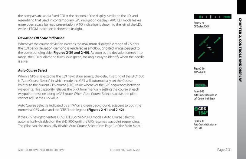
CHA
PTER 2, CO
NTR
OLS A
ND
DISPLAY
EFD1000 PFD Pilot’s Guide Page 2-31A-01-184-00 REV C / 091-00005-001 REV ( )
the compass arc, and a fixed CDI at the bottom of the display, similar to the LDI and resembling that used in contemporary GPS navigation displays. ARC CDI mode leaves more open space for map presentation. A TO indication is shown to the left of the LDI, while a FROM indication is shown to its right.
Deviation Off Scale Indication
Whenever the course deviation exceeds the maximum displayable range of 2.5 dots, the CDI bar or deviation diamond is rendered as a hollow, ghosted image pegged to the corresponding side (Figures 2-39 and 2-40). As soon as the deviation comes into range, the CDI or diamond turns solid green, making it easy to identify when the needle is alive.
Auto Course Select
When a GPS is selected as the CDI navigation source, the default setting of the EFD1000 is “Auto Course Select”, in which mode the GPS will automatically set the Course Pointer to the current GPS course (CRS) value whenever the GPS sequences between waypoints. This capability relieves the pilot from manually setting the course at each waypoint transition along a GPS route. When Auto Course Select is active, the pilot cannot adjust the CRS value.
Auto Course Select is indicated by an “A” on a green background, adjacent to both the numerical CRS value and the “CRS” knob legend (Figures 2-41 and 2-42).
If the GPS navigator enters OBS, HOLD, or SUSPEND modes, Auto Course Select is automatically disabled on the EFD1000 until the GPS resumes waypoint sequencing. The pilot can also manually disable Auto Course Select from Page 1 of the Main Menu.
Figure 2-39 Off Scale CDI
Figure 2-40Off Scale ARC CDI
Figure 2-41 Auto Course Indication on CRS Field
Figure 2-42 Auto Course Indication on Left Control Knob State
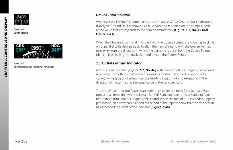
CHA
PTER
2, C
ON
TRO
LS A
ND
DIS
PLAY
EFD1000 PFD Pilot’s GuidePage 2-32 A-01-184-00 REV C / 091-00005-001 REV ( )
Ground Track Indicator
Whenever the EFD1000 is connected to a compatible GPS, a Ground Track Indicator is displayed. Ground Track is shown as a blue diamond rendered on the compass scale at the value that corresponds to the current aircraft track (Figure 2-2, No. 47 and Figure 2-43).
When the blue track diamond is aligned with the Course Pointer, the aircraft is tracking on or parallel to its desired track. To align the track diamond with the Course Pointer, turn away from the direction in which the diamond is offset from the Course Pointer (think of it as “pulling” the track diamond toward the Course Pointer).
2.3.3.2. Rate of Turn Indicator
A rate of turn indicator (Figure 2-2, No. 46) with a range of 0 to 6 degrees per second is provided for both the 360 and ARC Compass modes. The indicator consists of a curved white tape originating from the heading index mark and extending in the direction of the turn along the outer curve of the compass card.
The rate of turn indicator features an outer thick white tick mark for a Standard Rate turn, and an inner thin white tick mark for Half-Standard Rate turns. A Standard Rate, two-minute turn equals 3 degrees per second. When the rate of turn exceeds 6 degrees per second, an arrowhead is added to the end of the tape to show that the rate of turn has exceeded the limits of the indicator (Figure 2-44).
Figure 2-44 Rate of Turn Indicator, Rate Shown >6º/second
Figure 2-43 Current Heading
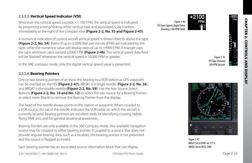
CHA
PTER 2, CO
NTR
OLS A
ND
DISPLAY
EFD1000 PFD Pilot’s Guide Page 2-33A-01-184-00 REV C / 091-00005-001 REV ( )
2.3.3.3. Vertical Speed Indicator (VSI)Whenever the vertical speed exceeds +/- 100 FPM, the vertical speed is indicated by presenting a rising/sinking white vertical tape and associated scale markers immediately to the right of the compass rose (Figure 2-2, No. 55 and Figure 2-45).
A numerical indication of current aircraft vertical speed is shown directly above the tape (Figure 2-2, No. 54). Rates of up to ±2000 feet per minute (FPM) are indicated by the tape, while the numerical value will display rates of up to ±9990 FPM. A triangle caps the tape whenever rates exceed ±2000 FPM (Figure 2-46). The vertical speed data field will be “dashed” whenever the vertical speed is 10,000 FPM or greater.
In the ARC compass mode, only the digital vertical speed value is presented.
2.3.3.4. Bearing PointersOne or two bearing pointers that show the bearing to a VOR station or GPS waypoint can be overlaid on the HSI (Figure 2-47). BRG#1 is a single needle (Figure 2-2, No. 56), and BRG#2 is the double needle (Figure 2-2, No. 59). Use the Nav Source Select Buttons (Figure 2-2, No. 10 and No. 12) to select the nav source for a Bearing Pointer, or select none (blank) to remove the Bearing Pointer from the display.
The head of the needle always points to the station or waypoint. When coupled to a VOR source, the tail of the needle indicates the VOR radial on which the aircraft is currently located. Bearing pointers are excellent tools for identifying crossing radials, flying DME arcs, and for general situational awareness.
Bearing Pointers are only available in the 360 Compass mode. Any available navigation source may be coupled to either bearing pointer. If coupled to a source that does not provide angular bearing data, such as a localizer, the bearing pointer is not presented and the source is flagged as invalid.
Each bearing pointer has an associated source information block that can display
Figure 2-45 VSI Tape Showing 300 FPM Descent
Figure 2-46 VSI Tape Capped, Digital Value
Showing 2,100 FPM Climb
Figure 2-47 BRG#1 Set to VOR1 on 117.9; BRG#2 Set to GPS2, SWR
CHA
PTER
2, C
ON
TRO
LS A
ND
DIS
PLAY
EFD1000 PFD Pilot’s GuidePage 2-34 A-01-184-00 REV C / 091-00005-001 REV ( )
information about the source of the bearing pointer data. Information that can be displayed includes distance to station (if coupled to a GPS waypoint) and either the station identifier or the tuned frequency for a VLOC radio. This information is only presented when it is reported to the EFD1000 by the connected equipment, and thus is not available in all installations.
2.3.3.5. Situational Awareness Map DisplayWhen the EFD1000 is connected to a compatible GPS navigator, a base map can be displayed underneath the HSI in either 360º or ARC modes. Most GPS put out data to enable the EFD1000 to display the active GPS flight plan legs and waypoints. The active GPS flight plan leg, waypoint, and its identifier are shown in magenta. Other waypoints and legs are shown in white.
Some GPS navigators (typically those using the ARINC 429 data protocol, such as the Garmin 400/500 series) additionally put out information on nearby nav data waypoints (e.g., airports, VORs, NDBs and intersections), which can also be displayed on the EFD1000 base map. These GPS can often also display curved flight paths, such as course reversals and holding patterns.
The base map is always oriented with magnetic heading up and centered so that the current aircraft position coincides with the aircraft ownship symbol. These base map elements underlay all other instruments and annunciations in the Navigation Display.
The MAP hot key is used to cycle through four levels of map features display and to

CHA
PTER 2, CO
NTR
OLS A
ND
DISPLAY
EFD1000 PFD Pilot’s Guide Page 2-35A-01-184-00 REV C / 091-00005-001 REV ( )
turn off the base map display. Each successive press of the MAP hot key selects the next feature level or OFF.
The map display range is controlled by the Range Control toggle button (Figure 2-2, Ref. 2), enabling the pilot to zoom in or out on the map. Automatic declutter logic changes the map features display depending on the selected map range.
The current map settings (range and feature level) are shown in the lower left-hand corner of the navigation display whenever the map is not OFF (Figure 2-48). The current map range is displayed in nautical miles, measuring the distance from the ownship symbol to the edge of the map display. The current map feature level is indicated by one to four green trapezoids underneath the range value (one mark is flight plan-only, while four marks is the highest map feature level).
Figure 2-48 Map in ARC Mode, 20nm Range at Feature Level 3 (Medium)

CHA
PTER
2, C
ON
TRO
LS A
ND
DIS
PLAY
EFD1000 PFD Pilot’s GuidePage 2-36 A-01-184-00 REV C / 091-00005-001 REV ( )
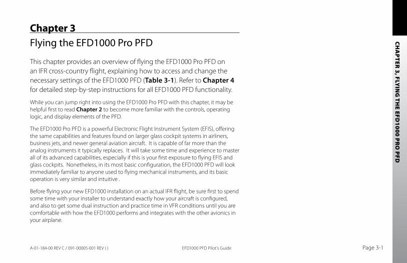
CHA
PTER 3, FLY
ING
THE EFD
1000 PRO
PFD
EFD1000 PFD Pilot’s Guide Page 3-1A-01-184-00 REV C / 091-00005-001 REV ( )
Chapter 3Flying the EFD1000 Pro PFD
This chapter provides an overview of flying the EFD1000 Pro PFD on an IFR cross-country flight, explaining how to access and change the necessary settings of the EFD1000 PFD (Table 3-1). Refer to Chapter 4 for detailed step-by-step instructions for all EFD1000 PFD functionality.
While you can jump right into using the EFD1000 Pro PFD with this chapter, it may be helpful first to read Chapter 2 to become more familiar with the controls, operating logic, and display elements of the PFD.
The EFD1000 Pro PFD is a powerful Electronic Flight Instrument System (EFIS), offering the same capabilities and features found on larger glass cockpit systems in airliners, business jets, and newer general aviation aircraft. It is capable of far more than the analog instruments it typically replaces. It will take some time and experience to master all of its advanced capabilities, especially if this is your first exposure to flying EFIS and glass cockpits. Nonetheless, in its most basic configuration, the EFD1000 PFD will look immediately familiar to anyone used to flying mechanical instruments, and its basic operation is very similar and intuitive .
Before flying your new EFD1000 installation on an actual IFR flight, be sure first to spend some time with your installer to understand exactly how your aircraft is configured, and also to get some dual instruction and practice time in VFR conditions until you are comfortable with how the EFD1000 performs and integrates with the other avionics in your airplane.
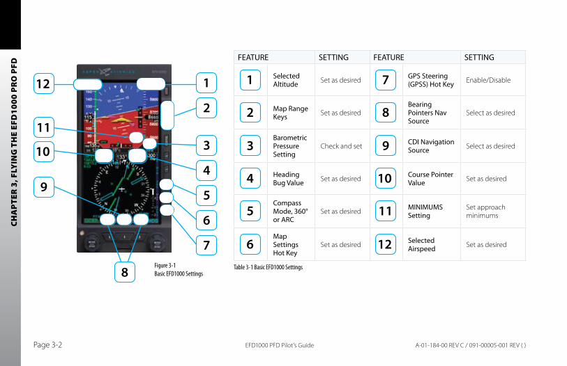
CHA
PTER
3, F
LYIN
G T
HE
EFD
1000
PR
O P
FD
EFD1000 PFD Pilot’s GuidePage 3-2 A-01-184-00 REV C / 091-00005-001 REV ( )
FEATURE SETTING FEATURE SETTING
Selected Altitude Set as desired GPS Steering
(GPSS) Hot Key Enable/Disable
Map Range Keys Set as desired
Bearing Pointers Nav Source
Select as desired
Barometric Pressure Setting
Check and set CDI Navigation Source Select as desired
Heading Bug Value Set as desired Course Pointer
Value Set as desired
Compass Mode, 360° or ARC
Set as desired MINIMUMS Setting
Set approach minimums
Map Settings Hot Key
Set as desired Selected Airspeed Set as desired
Table 3-1 Basic EFD1000 SettingsFigure 3-1 Basic EFD1000 Settings
CHA
PTER 3, FLY
ING
THE EFD
1000 PRO
PFD
EFD1000 PFD Pilot’s Guide Page 3-3A-01-184-00 REV C / 091-00005-001 REV ( )
3.1. Quick Controls OverviewChapter 2 explains the EFD1000 controls in detail. The following is a quick summary:
Control Knobs (see 2.2.1 for detail)
The Left and Right control knobs each has a Home state, to which it returns •after 10 seconds of inactivity. The left knob is the CRS knob, and the right knob is the HDG knob. The current function of each knob is shown by a legend on the screen •immediately above the knob. If the legend is shown in magenta, turning the knob will change the value of the function shown. If the legend is shown in cyan or green, turning the knob will have no effect. From the Home state, pressing the knob once will enable the current function •to be set (legend color changes from cyan to magenta). Successive presses of the knob will cycle through the functions that knob can control. When the function you want to change is shown in magenta, turning the knob will change the value. The Left control knob sets the Course Pointer (CRS, except when Auto Course •Select is enabled) and Indicated Airspeed Bug (IAS).The Right control knob sets Heading (HDG), Selected Altitude (ALT), •Barometric Pressure Setting (BARO), and Approach Minimums (MIN). Pressing and holding a knob syncs the function shown to the current value.•
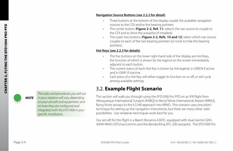
CHA
PTER
3, F
LYIN
G T
HE
EFD
1000
PR
O P
FD
EFD1000 PFD Pilot’s GuidePage 3-4 A-01-184-00 REV C / 091-00005-001 REV ( )
Navigation Source buttons (see 2.2.2 for detail)
Three buttons at the bottom of the display couple the available navigation •sources to the CDI and/or the bearing pointers.The center button (• Figure 2-2, Ref. 11) selects the nav source to couple to the CDI and to drive the autopilot (if installed).The outer two buttons (• Figure 2-2, Refs. 10 and 12) select which nav source couples to each of the two bearing pointers (or none to hide the bearing pointers).
Hot Keys (see 2.2.3 for details)
The five buttons on the lower right-hand side of the display are Hot Keys, •the function of which is shown by the legend on the screen immediately adjacent to each button.The current status of each Hot Key is shown by the legend, in GREEN if active •and in GRAY if inactive. Each press of a Hot Key will either toggle its function on or off, or will cycle •among available settings.
3.2. Example Flight ScenarioThis section will walk you through using the EFD1000 Pro PFD on an IFR flight from Albuquerque International Sunport (KABQ) to Reno/Tahoe International Airport (KRNO), flying Victor airways to the ILS16R approach into KRNO. This scenario uses one pilot’s technique for setting up the navigation instruments, but there are many other valid possibilities. Use whatever techniques work best for you.
Our aircraft for this flight is a Beech Bonanza A36TC, equipped with dual Garmin GNS-430W WAAS GPS/nav/comms and the Bendix/King KFC-200 autopilot. The EFD1000 Pro
NOTEThe tasks and procedures you will use in your airplane will vary depending on your aircraft and equipment, and on how they are configured and integrated with the EFD1000 in your specific installation.
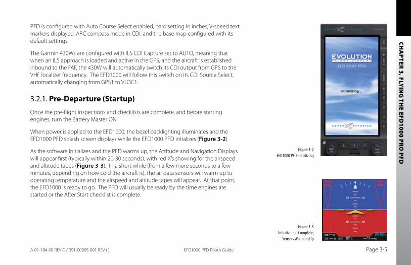
CHA
PTER 3, FLY
ING
THE EFD
1000 PRO
PFD
EFD1000 PFD Pilot’s Guide Page 3-5A-01-184-00 REV C / 091-00005-001 REV ( )
PFD is configured with Auto Course Select enabled, baro setting in inches, V-speed text markers displayed, ARC compass mode in CDI, and the base map configured with its default settings.
The Garmin 430Ws are configured with ILS CDI Capture set to AUTO, meaning that when an ILS approach is loaded and active in the GPS, and the aircraft is established inbound to the FAF, the 430W will automatically switch its CDI output from GPS to the VHF localizer frequency. The EFD1000 will follow this switch on its CDI Source Select, automatically changing from GPS1 to VLOC1.
3.2.1. Pre-Departure (Startup)
Once the pre-flight inspections and checklists are complete, and before starting engines, turn the Battery Master ON.
When power is applied to the EFD1000, the bezel backlighting illuminates and the EFD1000 PFD splash screen displays while the EFD1000 PFD intializes (Figure 3-2).
As the software initializes and the PFD warms up, the Attitude and Navigation Displays will appear first (typically within 20-30 seconds), with red X’s showing for the airspeed and altitude tapes (Figure 3-3). In a short while (from a few more seconds to a few minutes, depending on how cold the aircraft is), the air data sensors will warm up to operating temperature and the airspeed and altitude tapes will appear. At that point, the EFD1000 is ready to go. The PFD will usually be ready by the time engines are started or the After Start checklist is complete.
Figure 3-2 EFD1000 PFD Initializing
Figure 3-3 Initialization Complete,
Sensors Warming Up
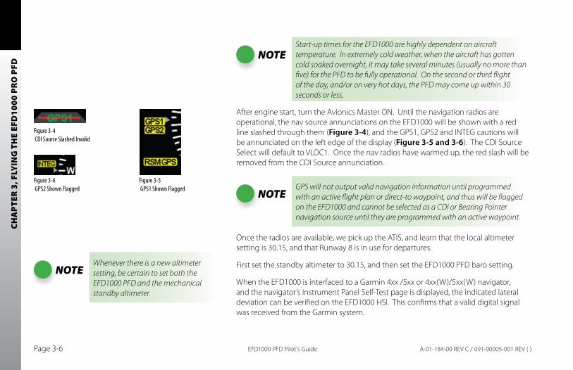
CHA
PTER
3, F
LYIN
G T
HE
EFD
1000
PR
O P
FD
EFD1000 PFD Pilot’s GuidePage 3-6 A-01-184-00 REV C / 091-00005-001 REV ( )
NOTEStart-up times for the EFD1000 are highly dependent on aircraft temperature. In extremely cold weather, when the aircraft has gotten cold soaked overnight, it may take several minutes (usually no more than five) for the PFD to be fully operational. On the second or third flight of the day, and/or on very hot days, the PFD may come up within 30 seconds or less.
After engine start, turn the Avionics Master ON. Until the navigation radios are operational, the nav source annunciations on the EFD1000 will be shown with a red line slashed through them (Figure 3-4), and the GPS1, GPS2 and INTEG cautions will be annunciated on the left edge of the display (Figure 3-5 and 3-6). The CDI Source Select will default to VLOC1. Once the nav radios have warmed up, the red slash will be removed from the CDI Source annunciation.
NOTEGPS will not output valid navigation information until programmed with an active flight plan or direct-to waypoint, and thus will be flagged on the EFD1000 and cannot be selected as a CDI or Bearing Pointer navigation source until they are programmed with an active waypoint.
Once the radios are available, we pick up the ATIS, and learn that the local altimeter setting is 30.15, and that Runway 8 is in use for departures.
First set the standby altimeter to 30.15, and then set the EFD1000 PFD baro setting.
When the EFD1000 is interfaced to a Garmin 4xx /5xx or 4xx(W)/5xx(W) navigator, and the navigator’s Instrument Panel Self-Test page is displayed, the indicated lateral deviation can be verified on the EFD1000 HSI. This confirms that a valid digital signal was received from the Garmin system.
Figure 3-4 CDI Source Slashed Invalid
Figure 3-5 GPS1 Shown Flagged
Figure 3-6 GPS2 Shown Flagged
NOTEWhenever there is a new altimeter setting, be certain to set both the EFD1000 PFD and the mechanical standby altimeter.
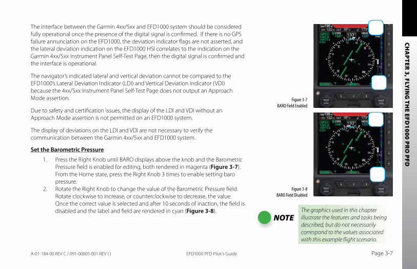
CHA
PTER 3, FLY
ING
THE EFD
1000 PRO
PFD
EFD1000 PFD Pilot’s Guide Page 3-7A-01-184-00 REV C / 091-00005-001 REV ( )
The interface between the Garmin 4xx/5xx and EFD1000 system should be considered fully operational once the presence of the digital signal is confirmed. If there is no GPS failure annunciation on the EFD1000, the deviation indicator flags are not asserted, and the lateral deviation indication on the EFD1000 HSI correlates to the indication on the Garmin 4xx/5xx Instrument Panel Self-Test Page, then the digital signal is confirmed and the interface is operational.
The navigator’s indicated lateral and vertical deviation cannot be compared to the EFD1000’s Lateral Deviation Indicator (LDI) and Vertical Deviation Indicator (VDI) because the 4xx/5xx Instrument Panel Self-Test Page does not output an Approach Mode assertion.
Due to safety and certification issues, the display of the LDI and VDI without an Approach Mode assertion is not permitted on an EFD1000 system.
The display of deviations on the LDI and VDI are not necessary to verify the communication between the Garmin 4xx/5xx and EFD1000 system.
Set the barometric Pressure
1. Press the Right Knob until BARO displays above the knob and the Barometric Pressure field is enabled for editing, both rendered in magenta (Figure 3-7). From the Home state, press the Right Knob 3 times to enable setting baro pressure.
2. Rotate the Right Knob to change the value of the Barometric Pressure field. Rotate clockwise to increase, or counterclockwise to decrease, the value. Once the correct value is selected and after 10 seconds of inaction, the field is disabled and the label and field are rendered in cyan (Figure 3-8).
Figure 3-7 BARO Field Enabled
Figure 3-8 BARO Field Disabled
NOTEThe graphics used in this chapter illustrate the features and tasks being described, but do not necessarily correspond to the values associated with this example flight scenario.
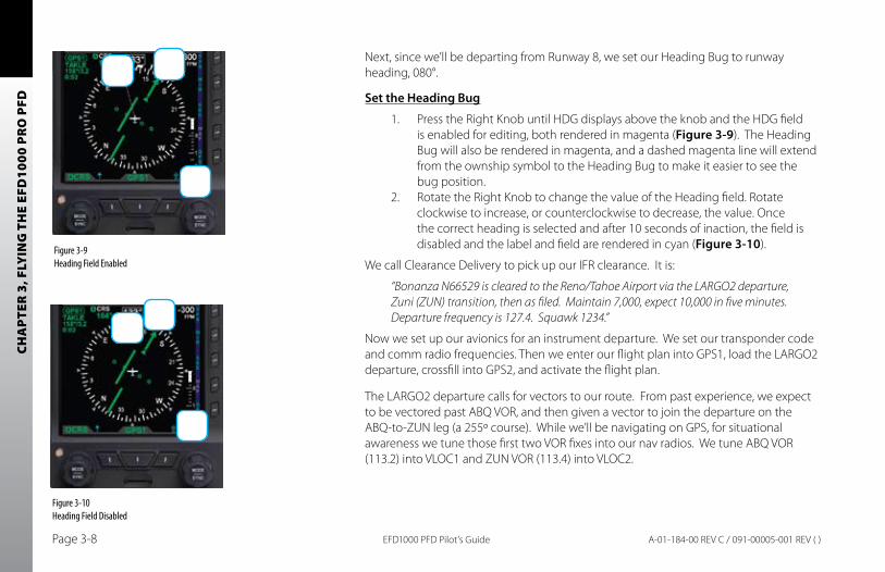
CHA
PTER
3, F
LYIN
G T
HE
EFD
1000
PR
O P
FD
EFD1000 PFD Pilot’s GuidePage 3-8 A-01-184-00 REV C / 091-00005-001 REV ( )
Next, since we’ll be departing from Runway 8, we set our Heading Bug to runway heading, 080°.
Set the Heading bug
1. Press the Right Knob until HDG displays above the knob and the HDG field is enabled for editing, both rendered in magenta (Figure 3-9). The Heading Bug will also be rendered in magenta, and a dashed magenta line will extend from the ownship symbol to the Heading Bug to make it easier to see the bug position.
2. Rotate the Right Knob to change the value of the Heading field. Rotate clockwise to increase, or counterclockwise to decrease, the value. Once the correct heading is selected and after 10 seconds of inaction, the field is disabled and the label and field are rendered in cyan (Figure 3-10).
We call Clearance Delivery to pick up our IFR clearance. It is:
“Bonanza N66529 is cleared to the Reno/Tahoe Airport via the LARGO2 departure, Zuni (ZUN) transition, then as filed. Maintain 7,000, expect 10,000 in five minutes. Departure frequency is 127.4. Squawk 1234.”
Now we set up our avionics for an instrument departure. We set our transponder code and comm radio frequencies. Then we enter our flight plan into GPS1, load the LARGO2 departure, crossfill into GPS2, and activate the flight plan.
The LARGO2 departure calls for vectors to our route. From past experience, we expect to be vectored past ABQ VOR, and then given a vector to join the departure on the ABQ-to-ZUN leg (a 255º course). While we’ll be navigating on GPS, for situational awareness we tune those first two VOR fixes into our nav radios. We tune ABQ VOR (113.2) into VLOC1 and ZUN VOR (113.4) into VLOC2.
Figure 3-9Heading Field Enabled
Figure 3-10 Heading Field Disabled
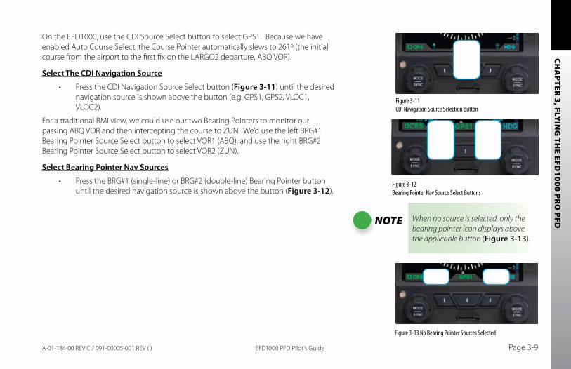
CHA
PTER 3, FLY
ING
THE EFD
1000 PRO
PFD
EFD1000 PFD Pilot’s Guide Page 3-9A-01-184-00 REV C / 091-00005-001 REV ( )
On the EFD1000, use the CDI Source Select button to select GPS1. Because we have enabled Auto Course Select, the Course Pointer automatically slews to 261º (the initial course from the airport to the first fix on the LARGO2 departure, ABQ VOR).
Select The CDI Navigation Source
Press the CDI Navigation Source Select button (• Figure 3-11) until the desired navigation source is shown above the button (e.g. GPS1, GPS2, VLOC1, VLOC2).
For a traditional RMI view, we could use our two Bearing Pointers to monitor our passing ABQ VOR and then intercepting the course to ZUN. We’d use the left BRG#1 Bearing Pointer Source Select button to select VOR1 (ABQ), and use the right BRG#2 Bearing Pointer Source Select button to select VOR2 (ZUN).
Select bearing Pointer Nav Sources
Press the BRG#1 (single-line) or BRG#2 (double-line) Bearing Pointer button •until the desired navigation source is shown above the button (Figure 3-12).
NOTE When no source is selected, only the bearing pointer icon displays above the applicable button (Figure 3-13).
Figure 3-11CDI Navigation Source Selection Button
Figure 3-12 Bearing Pointer Nav Source Select Buttons
Figure 3-13 No Bearing Pointer Sources Selected
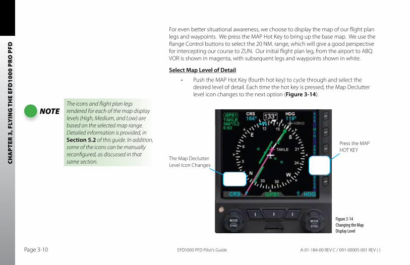
CHA
PTER
3, F
LYIN
G T
HE
EFD
1000
PR
O P
FD
EFD1000 PFD Pilot’s GuidePage 3-10 A-01-184-00 REV C / 091-00005-001 REV ( )
For even better situational awareness, we choose to display the map of our flight plan legs and waypoints. We press the MAP Hot Key to bring up the base map. We use the Range Control buttons to select the 20 NM. range, which will give a good perspective for intercepting our course to ZUN. Our initial flight plan leg, from the airport to ABQ VOR is shown in magenta, with subsequent legs and waypoints shown in white.
Select Map Level of Detail
Push the MAP Hot Key (fourth hot key) to cycle through and select the •desired level of detail. Each time the hot key is pressed, the Map Declutter level icon changes to the next option (Figure 3-14).
NOTEThe icons and flight plan legs rendered for each of the map display levels (High, Medium, and Low) are based on the selected map range. Detailed information is provided, in Section 5.2 of this guide. In addition, some of the icons can be manually reconfigured, as discussed in that same section.
Figure 3-14 Changing the Map Display Level
The Map Declutter Level Icon Changes
Press the MAP HOT KEY
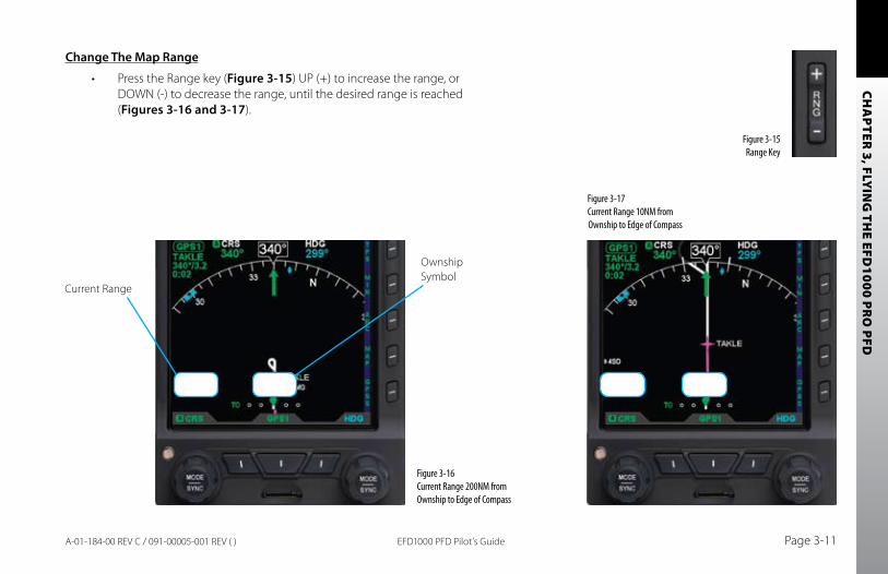
CHA
PTER 3, FLY
ING
THE EFD
1000 PRO
PFD
EFD1000 PFD Pilot’s Guide Page 3-11A-01-184-00 REV C / 091-00005-001 REV ( )
Change The Map Range
Press the Range key (• Figure 3-15) UP (+) to increase the range, or DOWN (-) to decrease the range, until the desired range is reached (Figures 3-16 and 3-17).
Figure 3-16 Current Range 200NM from Ownship to Edge of Compass
Figure 3-15 Range Key
Current Range
Ownship Symbol
Figure 3-17 Current Range 10NM from Ownship to Edge of Compass
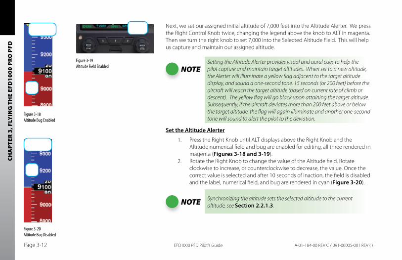
CHA
PTER
3, F
LYIN
G T
HE
EFD
1000
PR
O P
FD
EFD1000 PFD Pilot’s GuidePage 3-12 A-01-184-00 REV C / 091-00005-001 REV ( )
Next, we set our assigned initial altitude of 7,000 feet into the Altitude Alerter. We press the Right Control Knob twice, changing the legend above the knob to ALT in magenta. Then we turn the right knob to set 7,000 into the Selected Altitude Field. This will help us capture and maintain our assigned altitude.
NOTESetting the Altitude Alerter provides visual and aural cues to help the pilot capture and maintain target altitudes. When set to a new altitude, the Alerter will illuminate a yellow flag adjacent to the target altitude display, and sound a one-second tone, 15 seconds (or 200 feet) before the aircraft will reach the target altitude (based on current rate of climb or descent). The yellow flag will go black upon attaining the target altitude. Subsequently, if the aircraft deviates more than 200 feet above or below the target altitude, the flag will again illuminate and another one-second tone will sound to alert the pilot to the deviation.
Set the Altitude Alerter
1. Press the Right Knob until ALT displays above the Right Knob and the Altitude numerical field and bug are enabled for editing, all three rendered in magenta (Figures 3-18 and 3-19).
2. Rotate the Right Knob to change the value of the Altitude field. Rotate clockwise to increase, or counterclockwise to decrease, the value. Once the correct value is selected and after 10 seconds of inaction, the field is disabled and the label, numerical field, and bug are rendered in cyan (Figure 3-20).
NOTE Synchronizing the altitude sets the selected altitude to the current altitude, see Section 2.2.1.3.
Figure 3-18 Altitude Bug Enabled
Figure 3-20 Altitude Bug Disabled
Figure 3-19 Altitude Field Enabled
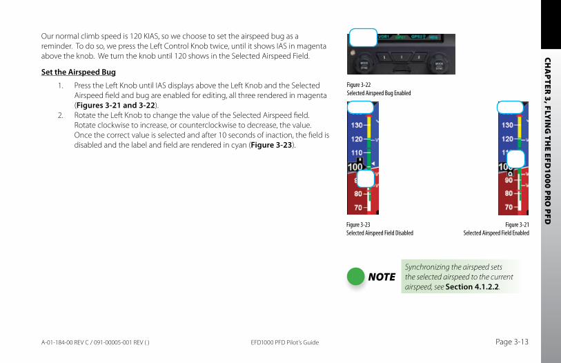
CHA
PTER 3, FLY
ING
THE EFD
1000 PRO
PFD
EFD1000 PFD Pilot’s Guide Page 3-13A-01-184-00 REV C / 091-00005-001 REV ( )
Our normal climb speed is 120 KIAS, so we choose to set the airspeed bug as a reminder. To do so, we press the Left Control Knob twice, until it shows IAS in magenta above the knob. We turn the knob until 120 shows in the Selected Airspeed Field.
Set the Airspeed bug
1. Press the Left Knob until IAS displays above the Left Knob and the Selected Airspeed field and bug are enabled for editing, all three rendered in magenta (Figures 3-21 and 3-22).
2. Rotate the Left Knob to change the value of the Selected Airspeed field. Rotate clockwise to increase, or counterclockwise to decrease, the value. Once the correct value is selected and after 10 seconds of inaction, the field is disabled and the label and field are rendered in cyan (Figure 3-23).
Figure 3-21 Selected Airspeed Field Enabled
Figure 3-23Selected Airspeed Field Disabled
Figure 3-22 Selected Airspeed Bug Enabled
NOTESynchronizing the airspeed sets the selected airspeed to the current airspeed, see Section 4.1.2.2.
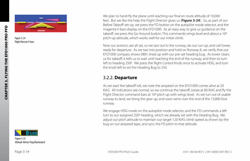
CHA
PTER
3, F
LYIN
G T
HE
EFD
1000
PR
O P
FD
EFD1000 PFD Pilot’s GuidePage 3-14 A-01-184-00 REV C / 091-00005-001 REV ( )
We plan to hand-fly the plane until reaching our final en route altitude of 10,000 feet. But we like the help the Flight Director gives us (Figure 3-24). So, as part of our Before Takeoff set-up, we press the FD button on the autopilot mode selector, and the magenta V-bars display on the EFD1000. As an easy way to give us guidance on the takeoff, we press the Go Around button. This commands wings level and about a 10º pitch-up attitude, which works well for our initial climb.
Now our avionics are all set, so we taxi out to the runway, do our run-up, and call tower, ready for departure. As we taxi into position and hold on Runway 8, we verify that our EFD1000 compass shows 080º, lined up with our pre-set heading bug. As tower clears us for takeoff, it tells us to wait until reaching the end of the runway, and then to turn left to heading 250º. We press the Right Control Knob once to activate HDG, and turn the knob left to set the Heading Bug to 250.
3.2.2. Departure
As we start the takeoff roll, we note the airspeed on the EFD1000 comes alive at 20 KIAS. All indications are normal, so we continue the takeoff, rotate at 80 KIAS and fly the Flight Director command bars at 10º pitch up with wings level. As we run out of usable runway to land, we bring the gear up, and soon we’re over the end of the 13,800 foot runway.
We engage HDG mode on the autopilot mode selector, and the FD commands a left turn to our assigned 250º heading, which we already set with the Heading Bug. We adjust our pitch attitude to maintain our target 120 KIAS climb speed as shown by the bug on our airspeed tape, and sync the FD pitch to that attitude.
Figure 3-24 Flight Director V-bars
Figure 3-25Altitude Alerter Flag Illuminated
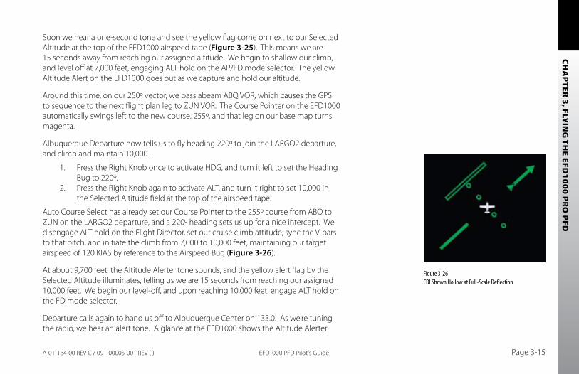
CHA
PTER 3, FLY
ING
THE EFD
1000 PRO
PFD
EFD1000 PFD Pilot’s Guide Page 3-15A-01-184-00 REV C / 091-00005-001 REV ( )
Soon we hear a one-second tone and see the yellow flag come on next to our Selected Altitude at the top of the EFD1000 airspeed tape (Figure 3-25). This means we are 15 seconds away from reaching our assigned altitude. We begin to shallow our climb, and level off at 7,000 feet, engaging ALT hold on the AP/FD mode selector. The yellow Altitude Alert on the EFD1000 goes out as we capture and hold our altitude.
Around this time, on our 250º vector, we pass abeam ABQ VOR, which causes the GPS to sequence to the next flight plan leg to ZUN VOR. The Course Pointer on the EFD1000 automatically swings left to the new course, 255º, and that leg on our base map turns magenta.
Albuquerque Departure now tells us to fly heading 220º to join the LARGO2 departure, and climb and maintain 10,000.
1. Press the Right Knob once to activate HDG, and turn it left to set the Heading Bug to 220º.
2. Press the Right Knob again to activate ALT, and turn it right to set 10,000 in the Selected Altitude field at the top of the airspeed tape.
Auto Course Select has already set our Course Pointer to the 255º course from ABQ to ZUN on the LARGO2 departure, and a 220º heading sets us up for a nice intercept. We disengage ALT hold on the Flight Director, set our cruise climb attitude, sync the V-bars to that pitch, and initiate the climb from 7,000 to 10,000 feet, maintaining our target airspeed of 120 KIAS by reference to the Airspeed Bug (Figure 3-26).
At about 9,700 feet, the Altitude Alerter tone sounds, and the yellow alert flag by the Selected Altitude illuminates, telling us we are 15 seconds from reaching our assigned 10,000 feet. We begin our level-off, and upon reaching 10,000 feet, engage ALT hold on the FD mode selector.
Departure calls again to hand us off to Albuquerque Center on 133.0. As we’re tuning the radio, we hear an alert tone. A glance at the EFD1000 shows the Altitude Alerter
Figure 3-26 CDI Shown Hollow at Full-Scale Deflection
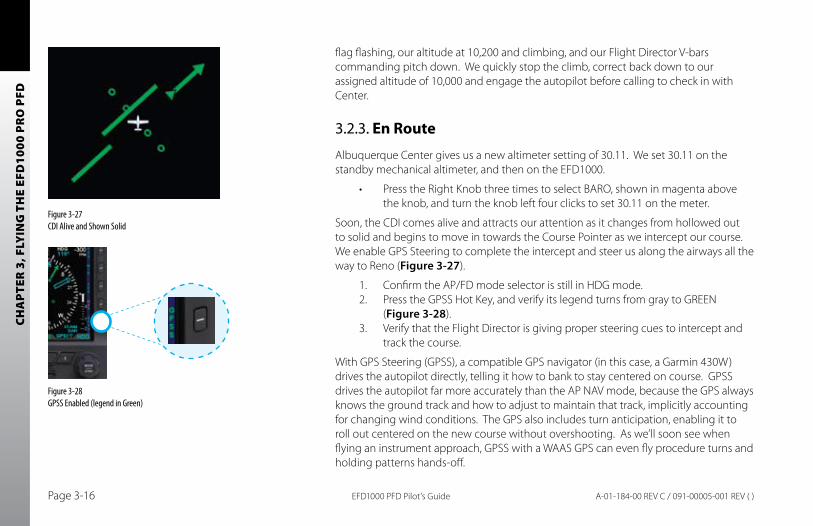
CHA
PTER
3, F
LYIN
G T
HE
EFD
1000
PR
O P
FD
EFD1000 PFD Pilot’s GuidePage 3-16 A-01-184-00 REV C / 091-00005-001 REV ( )
flag flashing, our altitude at 10,200 and climbing, and our Flight Director V-bars commanding pitch down. We quickly stop the climb, correct back down to our assigned altitude of 10,000 and engage the autopilot before calling to check in with Center.
3.2.3. En Route
Albuquerque Center gives us a new altimeter setting of 30.11. We set 30.11 on the standby mechanical altimeter, and then on the EFD1000.
Press the Right Knob three times to select BARO, shown in magenta above •the knob, and turn the knob left four clicks to set 30.11 on the meter.
Soon, the CDI comes alive and attracts our attention as it changes from hollowed out to solid and begins to move in towards the Course Pointer as we intercept our course. We enable GPS Steering to complete the intercept and steer us along the airways all the way to Reno (Figure 3-27).
1. Confirm the AP/FD mode selector is still in HDG mode.2. Press the GPSS Hot Key, and verify its legend turns from gray to GREEN
(Figure 3-28).3. Verify that the Flight Director is giving proper steering cues to intercept and
track the course.
With GPS Steering (GPSS), a compatible GPS navigator (in this case, a Garmin 430W) drives the autopilot directly, telling it how to bank to stay centered on course. GPSS drives the autopilot far more accurately than the AP NAV mode, because the GPS always knows the ground track and how to adjust to maintain that track, implicitly accounting for changing wind conditions. The GPS also includes turn anticipation, enabling it to roll out centered on the new course without overshooting. As we’ll soon see when flying an instrument approach, GPSS with a WAAS GPS can even fly procedure turns and holding patterns hands-off.
Figure 3-27 CDI Alive and Shown Solid
Figure 3-28 GPSS Enabled (legend in Green)
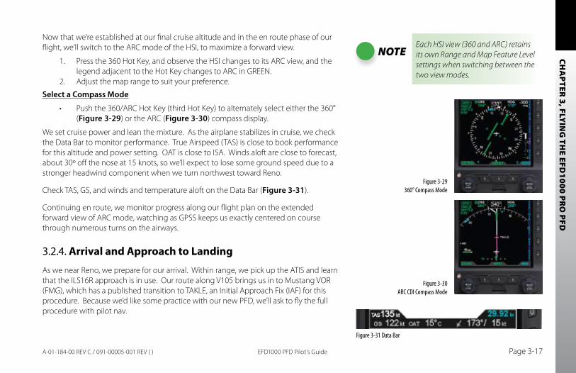
CHA
PTER 3, FLY
ING
THE EFD
1000 PRO
PFD
EFD1000 PFD Pilot’s Guide Page 3-17A-01-184-00 REV C / 091-00005-001 REV ( )
Now that we’re established at our final cruise altitude and in the en route phase of our flight, we’ll switch to the ARC mode of the HSI, to maximize a forward view.
1. Press the 360 Hot Key, and observe the HSI changes to its ARC view, and the legend adjacent to the Hot Key changes to ARC in GREEN.
2. Adjust the map range to suit your preference.
Select a Compass Mode
Push the 360/ARC Hot Key (third Hot Key) to alternately select either the 360° •(Figure 3-29) or the ARC (Figure 3-30) compass display.
We set cruise power and lean the mixture. As the airplane stabilizes in cruise, we check the Data Bar to monitor performance. True Airspeed (TAS) is close to book performance for this altitude and power setting. OAT is close to ISA. Winds aloft are close to forecast, about 30º off the nose at 15 knots, so we’ll expect to lose some ground speed due to a stronger headwind component when we turn northwest toward Reno.
Check TAS, GS, and winds and temperature aloft on the Data Bar (Figure 3-31).
Continuing en route, we monitor progress along our flight plan on the extended forward view of ARC mode, watching as GPSS keeps us exactly centered on course through numerous turns on the airways.
3.2.4. Arrival and Approach to Landing
As we near Reno, we prepare for our arrival. Within range, we pick up the ATIS and learn that the ILS16R approach is in use. Our route along V105 brings us in to Mustang VOR (FMG), which has a published transition to TAKLE, an Initial Approach Fix (IAF) for this procedure. Because we’d like some practice with our new PFD, we’ll ask to fly the full procedure with pilot nav.
NOTEEach HSI view (360 and ARC) retains its own Range and Map Feature Level settings when switching between the two view modes.
Figure 3-29 360° Compass Mode
Figure 3-30 ARC CDI Compass Mode
Figure 3-31 Data Bar
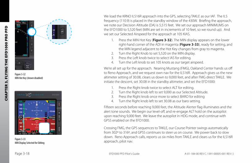
CHA
PTER
3, F
LYIN
G T
HE
EFD
1000
PR
O P
FD
EFD1000 PFD Pilot’s GuidePage 3-18 A-01-184-00 REV C / 091-00005-001 REV ( )
We load the KRNO ILS16R approach into the GPS, selecting TAKLE as our IAF. The ILS frequency (110.9) is placed in the standby window of the 430W. Briefing the approach, we note our Decision Altitude (DA) is 5,515 feet. We set our approach MINIMUMS on the EFD1000 to 5,520 feet (MIN are set in increments of 10 feet, so we round up). And we set our Selected Airspeed for the approach at 105 KIAS.
1. Press the MIN Hot Key (Figure 3-32). The MIN display appears on the lower right-hand corner of the ADI in magenta (Figure 3-33), ready for setting, and the MIN legend adjacent to the Hot Key changes from gray to magenta.
2. Turn the Right Knob to set 5,520 on the MIN display.3. Press the Left knob twice to select IAS for editing.4. Turn the Left knob to set 105 knots as our target airspeed.
We’re all set up for the approach. Nearing Mustang (FMG), Oakland Center hands us off to Reno Approach, and we request own nav for the ILS16R. Approach gives us the new altimeter setting of 30.08, clears us down to 9,000 feet, and after FMG direct TAKLE. We initiate the descent, set 30.08 in the standby altimeter, and set the EFD1000:
1. Press the Right knob twice to select ALT for editing.2. Turn the Right knob left to set 9,000 as our Selected Altitude.3. Press the Right knob once more to select BARO for editing4. Turn the Right knob left to set 30.08 as our baro setting.
Fifteen seconds before reaching 9,000 feet, the Altitude Alerter flag illuminates and the alert tone sounds. We begin our level-off, and re-engage ALT hold on the autopilot upon reaching 9,000 feet. We leave the autopilot in HDG mode, and continue with GPSS enabled on the EFD1000.
Crossing FMG, the GPS sequences to TAKLE, our Course Pointer swings automatically from 302º to 316º, and GPSS continues to steer us on course. We power back to slow down. Reno Approach calls, reports us six miles from TAKLE and clears us for the ILS16R approach, pilot nav.
Figure 3-32 MIN Hot Key (shown disabled)
Figure 3-33MIN Display Selected for Editing
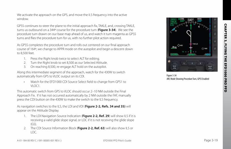
CHA
PTER 3, FLY
ING
THE EFD
1000 PRO
PFD
EFD1000 PFD Pilot’s Guide Page 3-19A-01-184-00 REV C / 091-00005-001 REV ( )
We activate the approach on the GPS, and move the ILS frequency into the active window.
GPSS continues to steer the plane to the initial approach fix, TAKLE, and, crossing TAKLE, turns us outbound on a 344º course for the procedure turn (Figure 3-34). We see the procedure turn drawn on our base map ahead of us, and watch it turn magenta as GPSS turns and flies the procedure turn for us, with no further pilot action required.
As GPSS completes the procedure turn and rolls out centered on our final approach course of 164º, we change to APPR mode on the autopilot and begin a descent down to 8,500 feet.
1. Press the Right knob twice to select ALT for editing.2. Turn the Right knob to set 8,500 as our Selected Altitude.3. On reaching 8,500, re-engage ALT hold on the autopilot.
Along this intermediate segment of the approach, watch for the 430W to switch automatically from GPS to VLOC output on its CDI.
Watch for the EFD1000 CDI Source Select field to change from GPS1 to •VLOC1.
This automatic switch from GPS to VLOC should occur 2–10 NM outside the Final Approach Fix. If it has not occurred automatically by 2 NM outside the FAF, manually press the CDI button on the 430W to make the switch to the ILS frequency.
As navigation switches to the ILS, the LDI and VDI (Figure 2-2, Refs. 34 and 35) will appear on the Attitude Display.
1. The LDI Navigation Source Indication (Figure 2-2, Ref. 29) will show ILS if it is receiving a valid glide slope signal, or LOC if it is not receiving the glide slope (GS).
2. The CDI Source Information Block (Figure 2-2, Ref. 63) will also show ILS or LOC.
Figure 3-34 ARC Mode Showing Procedure Turn, GPSS Enabled
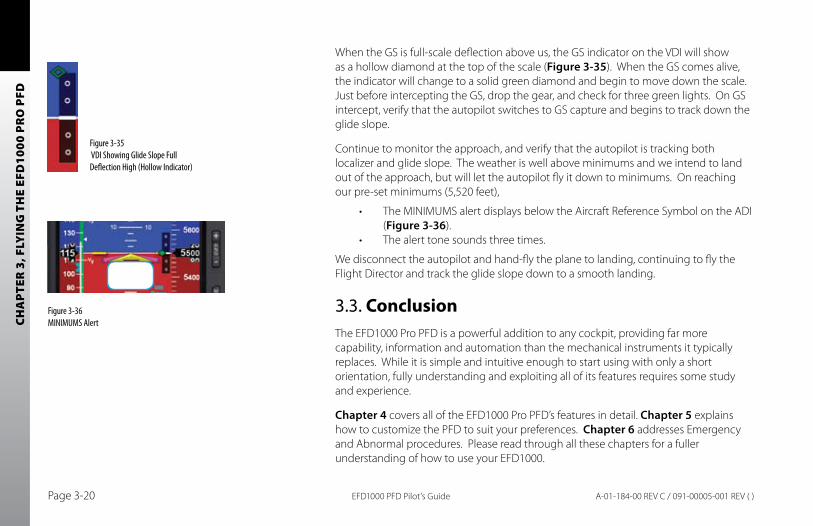
CHA
PTER
3, F
LYIN
G T
HE
EFD
1000
PR
O P
FD
EFD1000 PFD Pilot’s GuidePage 3-20 A-01-184-00 REV C / 091-00005-001 REV ( )
When the GS is full-scale deflection above us, the GS indicator on the VDI will show as a hollow diamond at the top of the scale (Figure 3-35). When the GS comes alive, the indicator will change to a solid green diamond and begin to move down the scale. Just before intercepting the GS, drop the gear, and check for three green lights. On GS intercept, verify that the autopilot switches to GS capture and begins to track down the glide slope.
Continue to monitor the approach, and verify that the autopilot is tracking both localizer and glide slope. The weather is well above minimums and we intend to land out of the approach, but will let the autopilot fly it down to minimums. On reaching our pre-set minimums (5,520 feet),
The MINIMUMS alert displays below the Aircraft Reference Symbol on the ADI •(Figure 3-36).The alert tone sounds three times.•
We disconnect the autopilot and hand-fly the plane to landing, continuing to fly the Flight Director and track the glide slope down to a smooth landing.
3.3. ConclusionThe EFD1000 Pro PFD is a powerful addition to any cockpit, providing far more capability, information and automation than the mechanical instruments it typically replaces. While it is simple and intuitive enough to start using with only a short orientation, fully understanding and exploiting all of its features requires some study and experience.
Chapter 4 covers all of the EFD1000 Pro PFD’s features in detail. Chapter 5 explains how to customize the PFD to suit your preferences. Chapter 6 addresses Emergency and Abnormal procedures. Please read through all these chapters for a fuller understanding of how to use your EFD1000.
Figure 3-35 VDI Showing Glide Slope Full Deflection High (Hollow Indicator)
Figure 3-36 MINIMUMS Alert
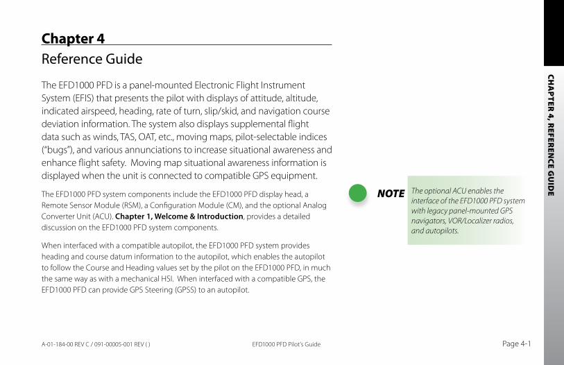
CHA
PTER 4, R
EFEREN
CE GU
IDE
EFD1000 PFD Pilot’s Guide Page 4-1A-01-184-00 REV C / 091-00005-001 REV ( )
Chapter 4Reference Guide
The EFD1000 PFD is a panel-mounted Electronic Flight Instrument System (EFIS) that presents the pilot with displays of attitude, altitude, indicated airspeed, heading, rate of turn, slip/skid, and navigation course deviation information. The system also displays supplemental flight data such as winds, TAS, OAT, etc., moving maps, pilot-selectable indices (“bugs”), and various annunciations to increase situational awareness and enhance flight safety. Moving map situational awareness information is displayed when the unit is connected to compatible GPS equipment.
The EFD1000 PFD system components include the EFD1000 PFD display head, a Remote Sensor Module (RSM), a Configuration Module (CM), and the optional Analog Converter Unit (ACU). Chapter 1, Welcome & Introduction, provides a detailed discussion on the EFD1000 PFD system components.
When interfaced with a compatible autopilot, the EFD1000 PFD system provides heading and course datum information to the autopilot, which enables the autopilot to follow the Course and Heading values set by the pilot on the EFD1000 PFD, in much the same way as with a mechanical HSI. When interfaced with a compatible GPS, the EFD1000 PFD can provide GPS Steering (GPSS) to an autopilot.
NOTE The optional ACU enables the interface of the EFD1000 PFD system with legacy panel-mounted GPS navigators, VOR/Localizer radios, and autopilots.
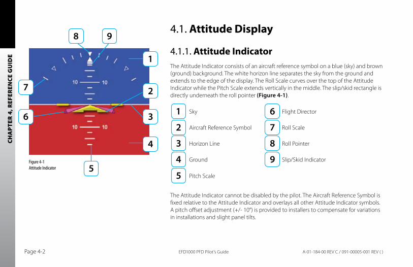
CHA
PTER
4, R
EFER
ENCE
GU
IDE
EFD1000 PFD Pilot’s GuidePage 4-2 A-01-184-00 REV C / 091-00005-001 REV ( )
4.1. Attitude Display
4.1.1. Attitude IndicatorThe Attitude Indicator consists of an aircraft reference symbol on a blue (sky) and brown (ground) background. The white horizon line separates the sky from the ground and extends to the edge of the display. The Roll Scale curves over the top of the Attitude Indicator while the Pitch Scale extends vertically in the middle. The slip/skid rectangle is directly underneath the roll pointer (Figure 4-1).
Sky Flight Director
Aircraft Reference Symbol Roll Scale
Horizon Line Roll Pointer
Ground Slip/Skid Indicator
Pitch Scale
The Attitude Indicator cannot be disabled by the pilot. The Aircraft Reference Symbol is fixed relative to the Attitude Indicator and overlays all other Attitude Indicator symbols. A pitch offset adjustment (+/- 10°) is provided to installers to compensate for variations in installations and slight panel tilts.
Figure 4-1 Attitude Indicator
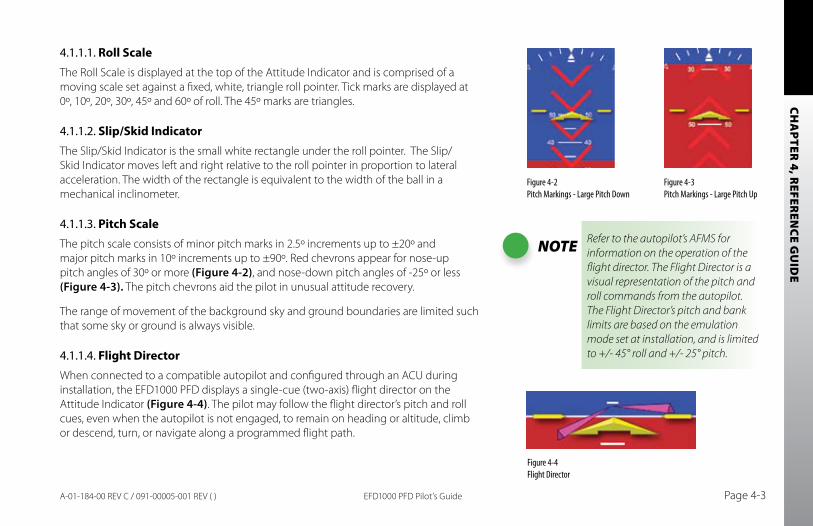
CHA
PTER 4, R
EFEREN
CE GU
IDE
EFD1000 PFD Pilot’s Guide Page 4-3A-01-184-00 REV C / 091-00005-001 REV ( )
4.1.1.1. Roll ScaleThe Roll Scale is displayed at the top of the Attitude Indicator and is comprised of a moving scale set against a fixed, white, triangle roll pointer. Tick marks are displayed at 0º, 10º, 20º, 30º, 45º and 60º of roll. The 45º marks are triangles.
4.1.1.2. Slip/Skid IndicatorThe Slip/Skid Indicator is the small white rectangle under the roll pointer. The Slip/Skid Indicator moves left and right relative to the roll pointer in proportion to lateral acceleration. The width of the rectangle is equivalent to the width of the ball in a mechanical inclinometer.
4.1.1.3. Pitch ScaleThe pitch scale consists of minor pitch marks in 2.5º increments up to ±20º and major pitch marks in 10º increments up to ±90º. Red chevrons appear for nose-up pitch angles of 30º or more (Figure 4-2), and nose-down pitch angles of -25º or less (Figure 4-3). The pitch chevrons aid the pilot in unusual attitude recovery.
The range of movement of the background sky and ground boundaries are limited such that some sky or ground is always visible.
4.1.1.4. Flight DirectorWhen connected to a compatible autopilot and configured through an ACU during installation, the EFD1000 PFD displays a single-cue (two-axis) flight director on the Attitude Indicator (Figure 4-4). The pilot may follow the flight director’s pitch and roll cues, even when the autopilot is not engaged, to remain on heading or altitude, climb or descend, turn, or navigate along a programmed flight path.
Figure 4-2 Pitch Markings - Large Pitch Down
Figure 4-3 Pitch Markings - Large Pitch Up
NOTE Refer to the autopilot’s AFMS for information on the operation of the flight director. The Flight Director is a visual representation of the pitch and roll commands from the autopilot. The Flight Director’s pitch and bank limits are based on the emulation mode set at installation, and is limited to +/- 45° roll and +/- 25° pitch.
Figure 4-4Flight Director
CHA
PTER
4, R
EFER
ENCE
GU
IDE
EFD1000 PFD Pilot’s GuidePage 4-4 A-01-184-00 REV C / 091-00005-001 REV ( )
4.1.1.5. Air Data and Attitude/Heading Reference System (ADAHRS)
The Aspen ADAHRS uses Microelectromechanical systems (MEMS) technology to provide attitude reference. The technology is different from legacy gyro systems and an understanding of the capability and limitations can be helpful to the operator.
Generally, MEMS attitude solutions use multiple inputs to derive and validate the attitude solution. The Aspen System uses more than a dozen inputs to determine and monitor the aircraft attitude. In this way the system can validate the derived attitude indication by cross-checking the various inputs to the solution for consistency with one another.
The Aspen ADAHRS solution uses inputs from its internal three-axis accelerometers, rate gyros and magnetometers, supplemented by pitot and static pressure inputs from the aircraft pitot-static system. Failures or incorrect input from any one of these sensors, such as might occur if the pitot tube or static system became blocked, will affect the attitude solution. These conditions are sensed by the system and a “Cross Check Attitude” annunciation is presented (Figure 4-5). It is possible for the attitude performance to be affected before the “Cross Check Attitude” annunciation, especially when there are accelerations imposed, such as during steep turns or abrupt pitch changes. An ADAHRS attitude discrepancy is generally obvious to the pilot, either by an anomalous behavior cross-checked against the stand by attitude, or by annunciation.
Operationally, it is important to preflight the aircraft to assure proper performance of the pitot and static systems, especially when anticipating low IMC. If there are issues
CHA
PTER 4, R
EFEREN
CE GU
IDE
EFD1000 PFD Pilot’s Guide Page 4-5A-01-184-00 REV C / 091-00005-001 REV ( )
with airspeed or altitude that are consistent with an obstructed pitot or static line, the pilot should recognize that the attitude indication will soon be compromised. If in IMC, immediately use the backup indicator to fly the airplane. If at any time there is even a momentary “Cross Check Attitude” warning, use the backup attitude indicator until the cause of the warning is corrected.
In summary, loss or degradation of the attitude solution is unlikely. If the pitot or static system becomes blocked, an ADAHRS internal sensor fails, or the “Cross Check Attitude” indication is presented for even a moment, the attitude indication on the PFD should be considered to be compromised. In this circumstance the pilot must use the backup attitude indicator for attitude reference until the cause of the problem is resolved.
4.1.1.6. Degraded ADAHRS PerformanceSee sections 6.1. In Flight ADAHRS Reset, 6.2. Pitot/Static System blockage, and 7.1.3. Geographic Limitations.
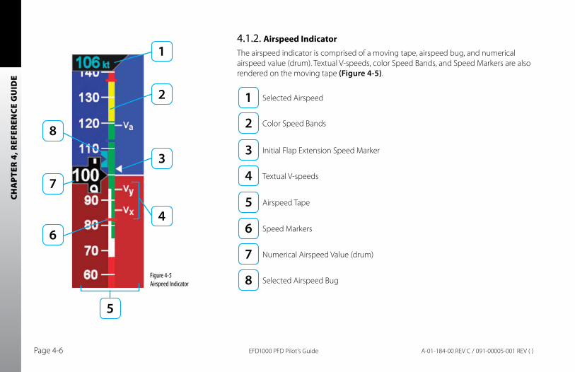
CHA
PTER
4, R
EFER
ENCE
GU
IDE
EFD1000 PFD Pilot’s GuidePage 4-6 A-01-184-00 REV C / 091-00005-001 REV ( )
4.1.2. Airspeed IndicatorThe airspeed indicator is comprised of a moving tape, airspeed bug, and numerical airspeed value (drum). Textual V-speeds, color Speed Bands, and Speed Markers are also rendered on the moving tape (Figure 4-5).
Figure 4-5 Airspeed Indicator
Selected Airspeed
Color Speed Bands
Initial Flap Extension Speed Marker
Textual V-speeds
Airspeed Tape
Speed Markers
Numerical Airspeed Value (drum)
Selected Airspeed Bug
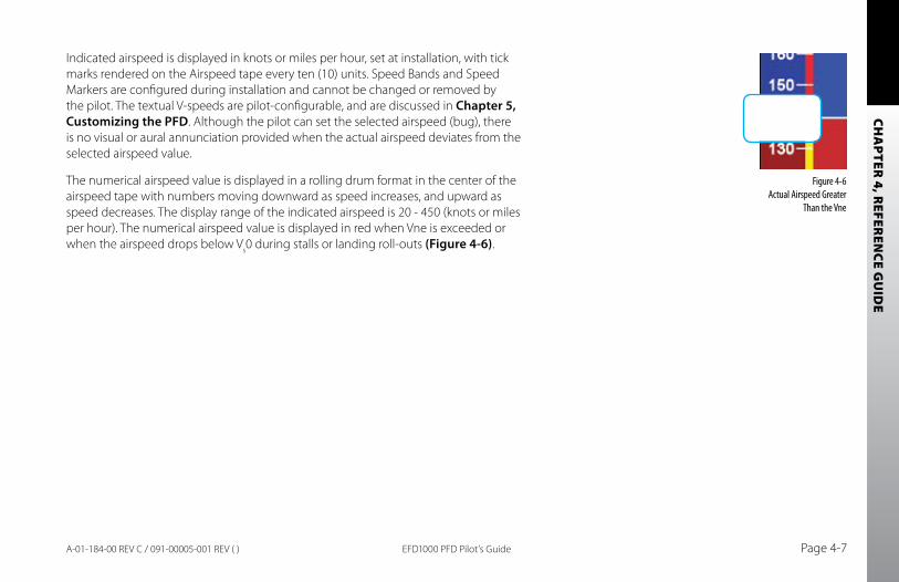
CHA
PTER 4, R
EFEREN
CE GU
IDE
EFD1000 PFD Pilot’s Guide Page 4-7A-01-184-00 REV C / 091-00005-001 REV ( )
Indicated airspeed is displayed in knots or miles per hour, set at installation, with tick marks rendered on the Airspeed tape every ten (10) units. Speed Bands and Speed Markers are configured during installation and cannot be changed or removed by the pilot. The textual V-speeds are pilot-configurable, and are discussed in Chapter 5, Customizing the PFD. Although the pilot can set the selected airspeed (bug), there is no visual or aural annunciation provided when the actual airspeed deviates from the selected airspeed value.
The numerical airspeed value is displayed in a rolling drum format in the center of the airspeed tape with numbers moving downward as speed increases, and upward as speed decreases. The display range of the indicated airspeed is 20 - 450 (knots or miles per hour). The numerical airspeed value is displayed in red when Vne is exceeded or when the airspeed drops below Vs0 during stalls or landing roll-outs (Figure 4-6).
Figure 4-6 Actual Airspeed Greater
Than the Vne
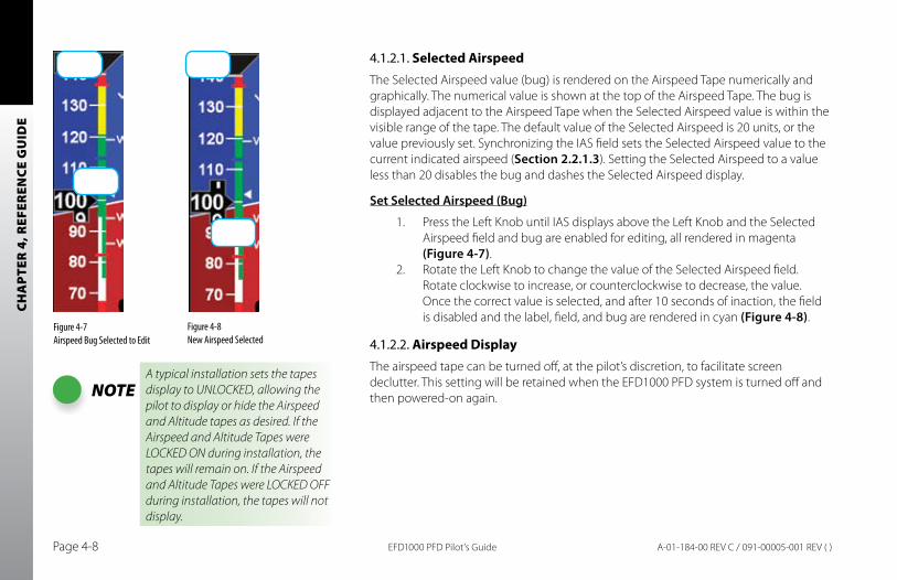
CHA
PTER
4, R
EFER
ENCE
GU
IDE
EFD1000 PFD Pilot’s GuidePage 4-8 A-01-184-00 REV C / 091-00005-001 REV ( )
4.1.2.1. Selected Airspeed The Selected Airspeed value (bug) is rendered on the Airspeed Tape numerically and graphically. The numerical value is shown at the top of the Airspeed Tape. The bug is displayed adjacent to the Airspeed Tape when the Selected Airspeed value is within the visible range of the tape. The default value of the Selected Airspeed is 20 units, or the value previously set. Synchronizing the IAS field sets the Selected Airspeed value to the current indicated airspeed (Section 2.2.1.3). Setting the Selected Airspeed to a value less than 20 disables the bug and dashes the Selected Airspeed display.
Set Selected Airspeed (bug)
1. Press the Left Knob until IAS displays above the Left Knob and the Selected Airspeed field and bug are enabled for editing, all rendered in magenta (Figure 4-7).
2. Rotate the Left Knob to change the value of the Selected Airspeed field. Rotate clockwise to increase, or counterclockwise to decrease, the value. Once the correct value is selected, and after 10 seconds of inaction, the field is disabled and the label, field, and bug are rendered in cyan (Figure 4-8).
4.1.2.2. Airspeed DisplayThe airspeed tape can be turned off, at the pilot’s discretion, to facilitate screen declutter. This setting will be retained when the EFD1000 PFD system is turned off and then powered-on again.
Figure 4-7 Airspeed Bug Selected to Edit
NOTEA typical installation sets the tapes display to UNLOCKED, allowing the pilot to display or hide the Airspeed and Altitude tapes as desired. If the Airspeed and Altitude Tapes were LOCKED ON during installation, the tapes will remain on. If the Airspeed and Altitude Tapes were LOCKED OFF during installation, the tapes will not display.
Figure 4-8 New Airspeed Selected
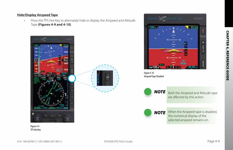
CHA
PTER 4, R
EFEREN
CE GU
IDE
EFD1000 PFD Pilot’s Guide Page 4-9A-01-184-00 REV C / 091-00005-001 REV ( )
Hide/Display Airspeed Tape
Press the TPS Hot Key to alternately hide or display the Airspeed and Altitude •Tape (Figures 4-9 and 4-10).
Figure 4-9 TPS Hot Key
Figure 4-10 Airspeed Tape Disabled
NOTE Both the Airspeed and Altitude tape are affected by this action.
NOTE When the Airspeed tape is disabled, the numerical display of the selected airspeed remains on.
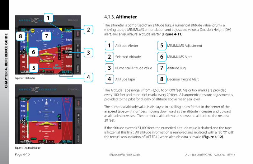
CHA
PTER
4, R
EFER
ENCE
GU
IDE
EFD1000 PFD Pilot’s GuidePage 4-10 A-01-184-00 REV C / 091-00005-001 REV ( )
4.1.3. Altimeter
The altimeter is comprised of an altitude bug, a numerical altitude value (drum), a moving tape, a MINIMUMS annunciation and adjustable value, a Decision Height (DH) alert, and a visual/aural altitude alerter (Figure 4-11).
Altitude Alerter MINIMUMS Adjustment
Selected Altitude MINIMUMS Alert
Numerical Altitude Value Altitude Bug
Altitude Tape Decision Height Alert
The Altitude Tape range is from -1,600 to 51,000 feet. Major tick marks are provided every 100 feet and minor tick marks every 20 feet. A barometric pressure adjustment is provided to the pilot for display of altitude above mean sea level.
The numerical altitude value is displayed in a rolling drum format in the center of the airspeed tape ,with numbers moving downward as the altitude increases and upward as altitude decreases. The numerical altitude value shows the altitude to the nearest 20 feet.
If the altitude exceeds 51,000 feet, the numerical altitude value is dashed and the tape is frozen at this limit. All altitude information is removed and replaced with a red “X” with the textual annunciation of “ALT FAIL,” when altitude data is invalid (Figure 4-12).
Figure 4-11 Altimeter
Figure 4-12 Altitude Failure
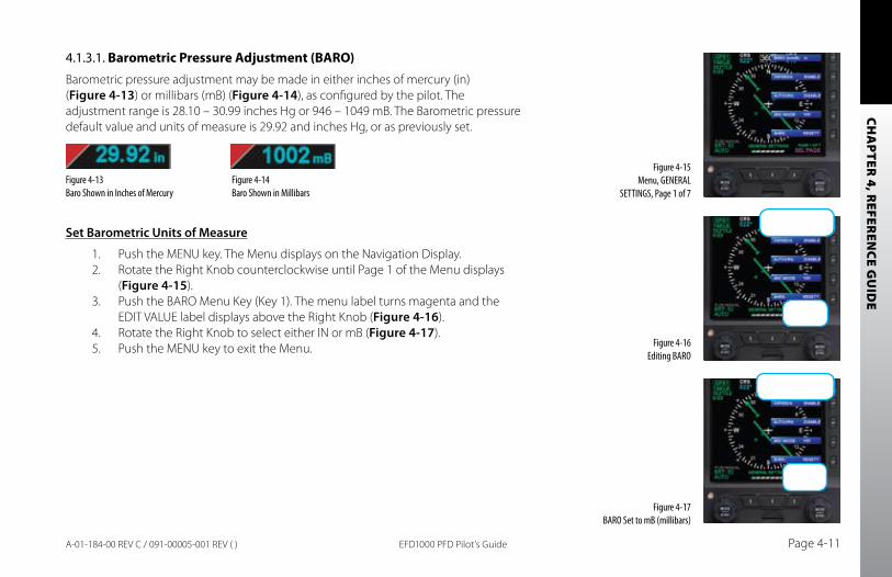
CHA
PTER 4, R
EFEREN
CE GU
IDE
EFD1000 PFD Pilot’s Guide Page 4-11A-01-184-00 REV C / 091-00005-001 REV ( )
4.1.3.1. Barometric Pressure Adjustment (BARO)Barometric pressure adjustment may be made in either inches of mercury (in) (Figure 4-13) or millibars (mB) (Figure 4-14), as configured by the pilot. The adjustment range is 28.10 – 30.99 inches Hg or 946 – 1049 mB. The Barometric pressure default value and units of measure is 29.92 and inches Hg, or as previously set.
Set barometric Units of Measure
1. Push the MENU key. The Menu displays on the Navigation Display.2. Rotate the Right Knob counterclockwise until Page 1 of the Menu displays
(Figure 4-15).3. Push the BARO Menu Key (Key 1). The menu label turns magenta and the
EDIT VALUE label displays above the Right Knob (Figure 4-16).4. Rotate the Right Knob to select either IN or mB (Figure 4-17).5. Push the MENU key to exit the Menu.
Figure 4-15 Menu, GENERAL
SETTINGS, Page 1 of 7
Figure 4-16 Editing BARO
Figure 4-17 BARO Set to mB (millibars)
Figure 4-13 Baro Shown in Inches of Mercury
Figure 4-14 Baro Shown in Millibars
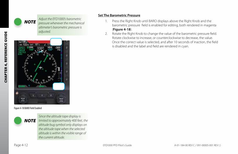
CHA
PTER
4, R
EFER
ENCE
GU
IDE
EFD1000 PFD Pilot’s GuidePage 4-12 A-01-184-00 REV C / 091-00005-001 REV ( )
Set The barometric Pressure
1. Press the Right Knob until BARO displays above the Right Knob and the barometric pressure field is enabled for editing, both rendered in magenta (Figure 4-18).
2. Rotate the Right Knob to change the value of the barometric pressure field. Rotate clockwise to increase, or counterclockwise to decrease, the value. Once the correct value is selected, and after 10 seconds of inaction, the field is disabled and the label and field are rendered in cyan.
Figure 4-18 BARO Field Enabled
NOTESince the altitude tape display is limited to approximately 400 feet, the altitude bug symbol only displays on the altitude tape when the selected altitude is within the visible range of the current altitude.
NOTEAdjust the EFD1000’s barometric pressure whenever the mechanical altimeter’s barometric pressure is adjusted.
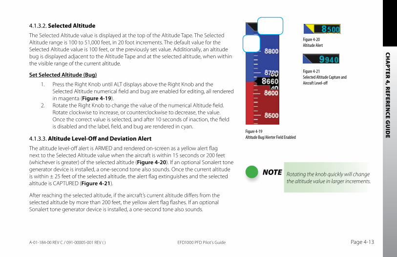
CHA
PTER 4, R
EFEREN
CE GU
IDE
EFD1000 PFD Pilot’s Guide Page 4-13A-01-184-00 REV C / 091-00005-001 REV ( )
4.1.3.2. Selected AltitudeThe Selected Altitude value is displayed at the top of the Altitude Tape. The Selected Altitude range is 100 to 51,000 feet, in 20 foot increments. The default value for the Selected Altitude value is 100 feet, or the previously set value. Additionally, an altitude bug is displayed adjacent to the Altitude Tape and at the selected altitude, when within the visible range of the current altitude.
Set Selected Altitude (bug)
1. Press the Right Knob until ALT displays above the Right Knob and the Selected Altitude numerical field and bug are enabled for editing, all rendered in magenta (Figure 4-19).
2. Rotate the Right Knob to change the value of the numerical Altitude field. Rotate clockwise to increase, or counterclockwise to decrease, the value. Once the correct value is selected, and after 10 seconds of inaction, the field is disabled and the label, field, and bug are rendered in cyan.
4.1.3.3. Altitude Level-Off and Deviation AlertThe altitude level-off alert is ARMED and rendered on-screen as a yellow alert flag next to the Selected Altitude value when the aircraft is within 15 seconds or 200 feet (whichever is greater) of the selected altitude (Figure 4-20). If an optional Sonalert tone generator device is installed, a one-second tone also sounds. Once the current altitude is within ± 25 feet of the selected altitude, the alert flag extinguishes and the selected altitude is CAPTURED (Figure 4-21).
After reaching the selected altitude, if the aircraft’s current altitude differs from the selected altitude by more than 200 feet, the yellow alert flag flashes. If an optional Sonalert tone generator device is installed, a one-second tone also sounds.
NOTE Rotating the knob quickly will change the altitude value in larger increments.
Figure 4-19 Altitude Bug/Alerter Field Enabled
Figure 4-20 Altitude Alert
Figure 4-21 Selected Altitude Capture and Aircraft Level-off
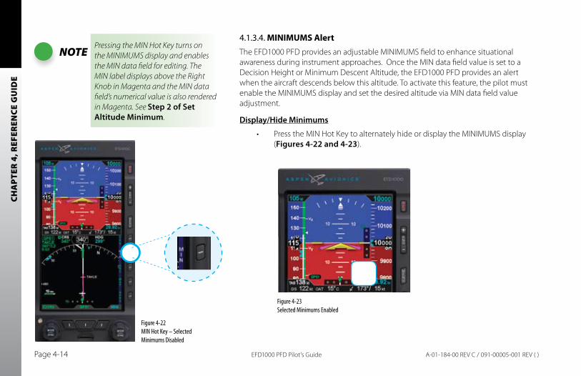
CHA
PTER
4, R
EFER
ENCE
GU
IDE
EFD1000 PFD Pilot’s GuidePage 4-14 A-01-184-00 REV C / 091-00005-001 REV ( )
4.1.3.4. MINIMUMS AlertThe EFD1000 PFD provides an adjustable MINIMUMS field to enhance situational awareness during instrument approaches. Once the MIN data field value is set to a Decision Height or Minimum Descent Altitude, the EFD1000 PFD provides an alert when the aircraft descends below this altitude. To activate this feature, the pilot must enable the MINIMUMS display and set the desired altitude via MIN data field value adjustment.
Display/Hide Minimums
Press the MIN Hot Key to alternately hide or display the MINIMUMS display •(Figures 4-22 and 4-23).
NOTEPressing the MIN Hot Key turns on the MINIMUMS display and enables the MIN data field for editing. The MIN label displays above the Right Knob in Magenta and the MIN data field’s numerical value is also rendered in Magenta. See Step 2 of Set Altitude Minimum.
Figure 4-22 MIN Hot Key – Selected Minimums Disabled
Figure 4-23 Selected Minimums Enabled
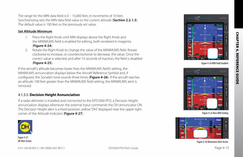
CHA
PTER 4, R
EFEREN
CE GU
IDE
EFD1000 PFD Pilot’s Guide Page 4-15A-01-184-00 REV C / 091-00005-001 REV ( )
Figure 4-24 MIN Field Enabled
Figure 4-25 New MIN Setting
The range for the MIN data field is 0 – 15,000 feet, in increments of 10 feet. Synchronizing sets the MIN data field value to the current altitude (Section 2.2.1.3). The default value is 100 feet or the previously set value.
Set Altitude Minimum
1. Press the Right Knob until MIN displays above the Right Knob and the MINIMUMS field is enabled for editing, both rendered in magenta (Figure 4-24).
2. Rotate the Right Knob to change the value of the MINIMUMS field. Rotate clockwise to increase, or counterclockwise to decrease, the value. Once the correct value is selected, and after 10 seconds of inaction, the field is disabled (Figure 4-25).
If the aircraft’s altitude becomes lower than the MINIMUMS field’s setting, the MINIMUMS annunciation displays below the Aircraft Reference Symbol and, if configured, the Sonalert tone sounds three times (Figure 4-26). If the aircraft reaches an altitude 100 feet greater than the MINIMUMS field setting, the MINIMUMS alert is removed.
4.1.3.5. Decision Height AnnunciationIf a radar altimeter is installed and connected to the EFD1000 PFD, a Decision Height annunciation displays whenever the external input commands the DH annunciator ON. The Decision Height alert is a fixed-position, yellow “DH,” displayed near the upper right corner of the Attitude Indicator (Figure 4-27).
Figure 4-26 Minimums Alert ActiveFigure 4-27 DH Alert Active
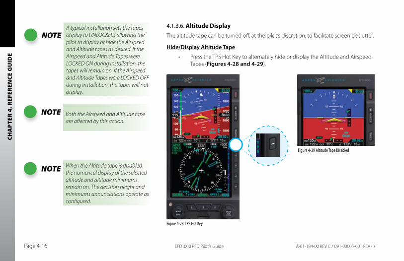
CHA
PTER
4, R
EFER
ENCE
GU
IDE
EFD1000 PFD Pilot’s GuidePage 4-16 A-01-184-00 REV C / 091-00005-001 REV ( )
4.1.3.6. Altitude DisplayThe altitude tape can be turned off, at the pilot’s discretion, to facilitate screen declutter.
Hide/Display Altitude Tape
Press the TPS Hot Key to alternately hide or display the Altitude and Airspeed •Tapes (Figures 4-28 and 4-29).
Figure 4-29 Altitude Tape Disabled
Figure 4-28 TPS Hot Key
NOTEA typical installation sets the tapes display to UNLOCKED, allowing the pilot to display or hide the Airspeed and Altitude tapes as desired. If the Airspeed and Altitude Tapes were LOCKED ON during installation, the tapes will remain on. If the Airspeed and Altitude Tapes were LOCKED OFF during installation, the tapes will not display.
NOTE Both the Airspeed and Altitude tape are affected by this action.
NOTE When the Altitude tape is disabled, the numerical display of the selected altitude and altitude minimums remain on. The decision height and minimums annunciations operate as configured.
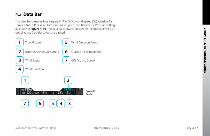
CHA
PTER 4, R
EFEREN
CE GU
IDE
EFD1000 PFD Pilot’s Guide Page 4-17A-01-184-00 REV C / 091-00005-001 REV ( )
4.2. Data BarThe Data Bar presents True Airspeed (TAS), GPS Ground Speed (GS), Outside Air Temperature (OAT), Wind Direction, Wind Speed, and Barometric Pressure Setting as shown in Figure 4-30. The data bar is always present on the display. Invalid or out-of-range Data Bar values are dashed.
True Airspeed Wind Direction Arrow
Barometric Pressure Setting Outside Air Temperature
Wind Speed GPS Ground Speed
Wind Direction
Figure 4-30 Data Bar
CHA
PTER
4, R
EFER
ENCE
GU
IDE
EFD1000 PFD Pilot’s GuidePage 4-18 A-01-184-00 REV C / 091-00005-001 REV ( )
4.2.1. True Airspeed
The True Airspeed (TAS) is displayed on the upper left of the Data Bar with a value range of 20 – 999 knots or mph, using the same unit of measurement as the Airspeed Indicator. The TAS is a correction of the IAS for nonstandard pressure and temperature.
4.2.2. Ground Speed
The Ground Speed (GS) is digitally displayed on the lower left corner of the Data Bar with a value range of 5 – 999 knots or mph, using the same unit of measurement as the Airspeed Indicator.
4.2.3. Outside Air Temperature
The Outside Air Temperature (OAT) is digitally displayed on the center of the Data Bar. The temperature is obtained from the temperature sensor located in the RSM and rendered in degrees Celsius (C) ranging from -99 – 999 degrees.
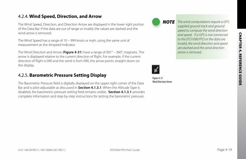
CHA
PTER 4, R
EFEREN
CE GU
IDE
EFD1000 PFD Pilot’s Guide Page 4-19A-01-184-00 REV C / 091-00005-001 REV ( )
4.2.4. Wind Speed, Direction, and Arrow
The Wind Speed, Direction, and Direction Arrow are displayed in the lower right portion of the Data Bar. If the data are out of range or invalid, the values are dashed and the wind arrow is removed.
The Wind Speed has a range of 10 – 999 knots or mph, using the same unit of measurement as the Airspeed Indicator.
The Wind Direction and Arrow (Figure 4-31) have a range of 001° – 360°, magnetic. The arrow is displayed relative to the current direction of flight. For example, if the current direction of flight is 090 and the wind is from 090, the arrow points straight down on the display.
4.2.5. Barometric Pressure Setting Display
The Barometric Pressure field is digitally displayed on the upper right corner of the Data Bar and is pilot-adjustable as discussed in Section 4.1.3.1. When the Altitude Tape is disabled, the barometric pressure setting field remains visible. Section 4.1.3.1 provides complete information and step-by-step instructions for setting the barometric pressure.
NOTE The wind computations require a GPS-supplied ground track and ground speed to compute the wind direction and speed. If a GPS is not connected to the EFD1000 PFD or the data are invalid, the wind direction and speed are dashed and the wind direction arrow is removed..
Figure 4-31 Wind Direction Arrow
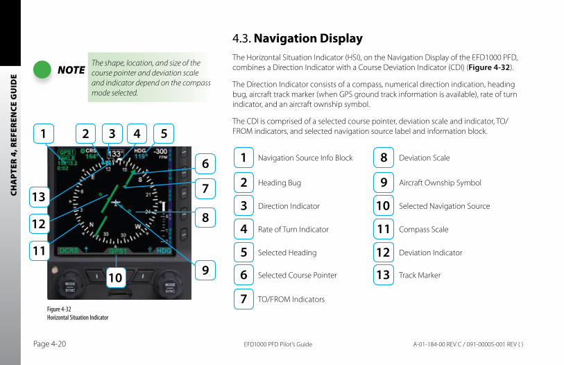
CHA
PTER
4, R
EFER
ENCE
GU
IDE
EFD1000 PFD Pilot’s GuidePage 4-20 A-01-184-00 REV C / 091-00005-001 REV ( )
4.3. Navigation DisplayThe Horizontal Situation Indicator (HSI), on the Navigation Display of the EFD1000 PFD, combines a Direction Indicator with a Course Deviation Indicator (CDI) (Figure 4-32).
The Direction Indicator consists of a compass, numerical direction indication, heading bug, aircraft track marker (when GPS ground track information is available), rate of turn indicator, and an aircraft ownship symbol.
The CDI is comprised of a selected course pointer, deviation scale and indicator, TO/FROM indicators, and selected navigation source label and information block.
Navigation Source Info Block Deviation Scale
Heading Bug Aircraft Ownship Symbol
Direction Indicator Selected Navigation Source
Rate of Turn Indicator Compass Scale
Selected Heading Deviation Indicator
Selected Course Pointer Track Marker
TO/FROM Indicators
NOTEThe shape, location, and size of the course pointer and deviation scale and indicator depend on the compass mode selected.
Figure 4-32 Horizontal Situation Indicator
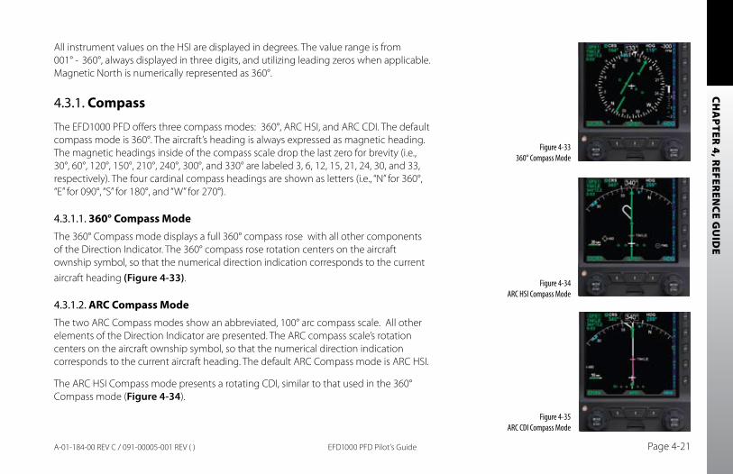
CHA
PTER 4, R
EFEREN
CE GU
IDE
EFD1000 PFD Pilot’s Guide Page 4-21A-01-184-00 REV C / 091-00005-001 REV ( )
All instrument values on the HSI are displayed in degrees. The value range is from 001° - 360°, always displayed in three digits, and utilizing leading zeros when applicable. Magnetic North is numerically represented as 360°.
4.3.1. Compass
The EFD1000 PFD offers three compass modes: 360°, ARC HSI, and ARC CDI. The default compass mode is 360°. The aircraft’s heading is always expressed as magnetic heading. The magnetic headings inside of the compass scale drop the last zero for brevity (i.e., 30°, 60°, 120°, 150°, 210°, 240°, 300°, and 330° are labeled 3, 6, 12, 15, 21, 24, 30, and 33, respectively). The four cardinal compass headings are shown as letters (i.e., “N” for 360°, “E” for 090°, “S” for 180°, and “W” for 270°).
4.3.1.1. 360° Compass ModeThe 360° Compass mode displays a full 360° compass rose with all other components of the Direction Indicator. The 360° compass rose rotation centers on the aircraft ownship symbol, so that the numerical direction indication corresponds to the current aircraft heading (Figure 4-33).
4.3.1.2. ARC Compass ModeThe two ARC Compass modes show an abbreviated, 100° arc compass scale. All other elements of the Direction Indicator are presented. The ARC compass scale’s rotation centers on the aircraft ownship symbol, so that the numerical direction indication corresponds to the current aircraft heading. The default ARC Compass mode is ARC HSI.
The ARC HSI Compass mode presents a rotating CDI, similar to that used in the 360° Compass mode (Figure 4-34).
Figure 4-33 360° Compass Mode
Figure 4-34 ARC HSI Compass Mode
Figure 4-35 ARC CDI Compass Mode
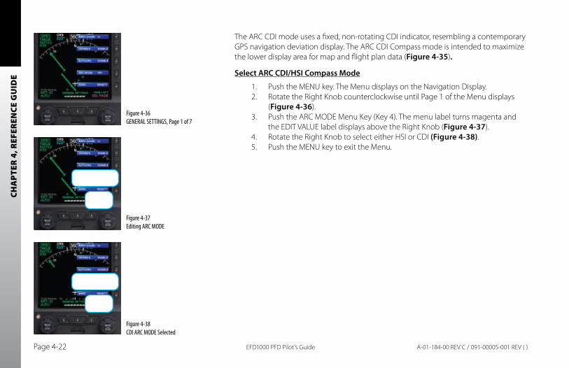
CHA
PTER
4, R
EFER
ENCE
GU
IDE
EFD1000 PFD Pilot’s GuidePage 4-22 A-01-184-00 REV C / 091-00005-001 REV ( )
The ARC CDI mode uses a fixed, non-rotating CDI indicator, resembling a contemporary GPS navigation deviation display. The ARC CDI Compass mode is intended to maximize the lower display area for map and flight plan data (Figure 4-35).
Select ARC CDI/HSI Compass Mode
1. Push the MENU key. The Menu displays on the Navigation Display.2. Rotate the Right Knob counterclockwise until Page 1 of the Menu displays
(Figure 4-36).3. Push the ARC MODE Menu Key (Key 4). The menu label turns magenta and
the EDIT VALUE label displays above the Right Knob (Figure 4-37).4. Rotate the Right Knob to select either HSI or CDI (Figure 4-38).5. Push the MENU key to exit the Menu.
Figure 4-37 Editing ARC MODE
Figure 4-38 CDI ARC MODE Selected
Figure 4-36 GENERAL SETTINGS, Page 1 of 7
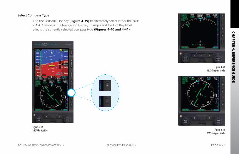
CHA
PTER 4, R
EFEREN
CE GU
IDE
EFD1000 PFD Pilot’s Guide Page 4-23A-01-184-00 REV C / 091-00005-001 REV ( )
Select Compass Type
Push the 360/ARC Hot Key• (Figure 4-39) to alternately select either the 360° or ARC Compass. The Navigation Display changes and the Hot Key label reflects the currently selected compass type (Figures 4-40 and 4-41).
Figure 4-39 360/ARC Hot Key Figure 4-41
360˚ Compass Mode
Figure 4-40 ARC Compass Mode
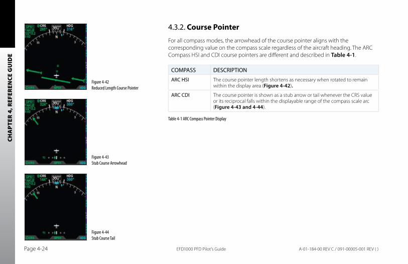
CHA
PTER
4, R
EFER
ENCE
GU
IDE
EFD1000 PFD Pilot’s GuidePage 4-24 A-01-184-00 REV C / 091-00005-001 REV ( )
4.3.2. Course Pointer
For all compass modes, the arrowhead of the course pointer aligns with the corresponding value on the compass scale regardless of the aircraft heading. The ARC Compass HSI and CDI course pointers are different and described in Table 4-1.
COMPASS DESCRIPTION
ARC HSI The course pointer length shortens as necessary when rotated to remain within the display area (Figure 4-42).
ARC CDI The course pointer is shown as a stub arrow or tail whenever the CRS value or its reciprocal falls within the displayable range of the compass scale arc (Figure 4-43 and 4-44).
Table 4-1 ARC Compass Pointer Display
Figure 4-42 Reduced Length Course Pointer
Figure 4-44 Stub Course Tail
Figure 4-43 Stub Course Arrowhead
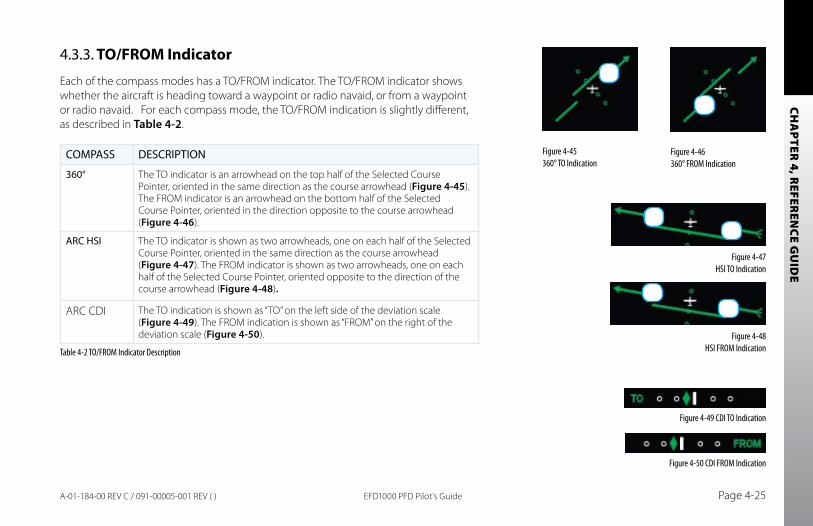
CHA
PTER 4, R
EFEREN
CE GU
IDE
EFD1000 PFD Pilot’s Guide Page 4-25A-01-184-00 REV C / 091-00005-001 REV ( )
4.3.3. TO/FROM Indicator
Each of the compass modes has a TO/FROM indicator. The TO/FROM indicator shows whether the aircraft is heading toward a waypoint or radio navaid, or from a waypoint or radio navaid. For each compass mode, the TO/FROM indication is slightly different, as described in Table 4-2.
COMPASS DESCRIPTION
360° The TO indicator is an arrowhead on the top half of the Selected Course Pointer, oriented in the same direction as the course arrowhead (Figure 4-45). The FROM indicator is an arrowhead on the bottom half of the Selected Course Pointer, oriented in the direction opposite to the course arrowhead (Figure 4-46).
ARC HSI The TO indicator is shown as two arrowheads, one on each half of the Selected Course Pointer, oriented in the same direction as the course arrowhead (Figure 4-47). The FROM indicator is shown as two arrowheads, one on each half of the Selected Course Pointer, oriented opposite to the direction of the course arrowhead (Figure 4-48).
ARC CDI The TO indication is shown as “TO” on the left side of the deviation scale (Figure 4-49). The FROM indication is shown as “FROM” on the right of the deviation scale (Figure 4-50).
Table 4-2 TO/FROM Indicator Description
Figure 4-50 CDI FROM Indication
Figure 4-48 HSI FROM Indication
Figure 4-47 HSI TO Indication
Figure 4-49 CDI TO Indication
Figure 4-46 360° FROM Indication
Figure 4-45 360° TO Indication
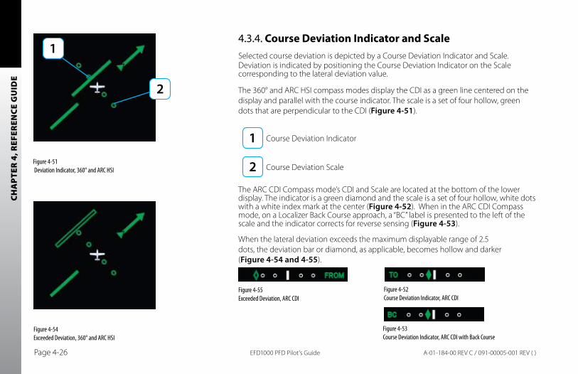
CHA
PTER
4, R
EFER
ENCE
GU
IDE
EFD1000 PFD Pilot’s GuidePage 4-26 A-01-184-00 REV C / 091-00005-001 REV ( )
4.3.4. Course Deviation Indicator and ScaleSelected course deviation is depicted by a Course Deviation Indicator and Scale. Deviation is indicated by positioning the Course Deviation Indicator on the Scale corresponding to the lateral deviation value.
The 360° and ARC HSI compass modes display the CDI as a green line centered on the display and parallel with the course indicator. The scale is a set of four hollow, green dots that are perpendicular to the CDI (Figure 4-51).
Course Deviation Indicator
Course Deviation Scale
The ARC CDI Compass mode’s CDI and Scale are located at the bottom of the lower display. The indicator is a green diamond and the scale is a set of four hollow, white dots with a white index mark at the center (Figure 4-52). When in the ARC CDI Compass mode, on a Localizer Back Course approach, a “BC” label is presented to the left of the scale and the indicator corrects for reverse sensing (Figure 4-53).
When the lateral deviation exceeds the maximum displayable range of 2.5 dots, the deviation bar or diamond, as applicable, becomes hollow and darker (Figure 4-54 and 4-55).
Figure 4-51 Deviation Indicator, 360° and ARC HSI
Figure 4-54 Exceeded Deviation, 360° and ARC HSI
Figure 4-52 Course Deviation Indicator, ARC CDI
Figure 4-53 Course Deviation Indicator, ARC CDI with Back Course
Figure 4-55 Exceeded Deviation, ARC CDI
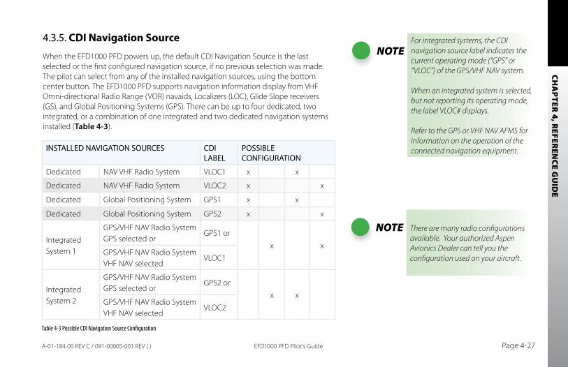
CHA
PTER 4, R
EFEREN
CE GU
IDE
EFD1000 PFD Pilot’s Guide Page 4-27A-01-184-00 REV C / 091-00005-001 REV ( )
4.3.5. CDI Navigation Source
When the EFD1000 PFD powers up, the default CDI Navigation Source is the last selected or the first configured navigation source, if no previous selection was made. The pilot can select from any of the installed navigation sources, using the bottom center button. The EFD1000 PFD supports navigation information display from VHF Omni-directional Radio Range (VOR) navaids, Localizers (LOC), Glide Slope receivers (GS), and Global Positioning Systems (GPS). There can be up to four dedicated, two integrated, or a combination of one integrated and two dedicated navigation systems installed (Table 4-3).
INSTALLED NAVIGATION SOURCES CDI LABEL
POSSIBLE CONFIGURATION
Dedicated NAV VHF Radio System VLOC1 x x
Dedicated NAV VHF Radio System VLOC2 x x
Dedicated Global Positioning System GPS1 x x
Dedicated Global Positioning System GPS2 x x
Integrated System 1
GPS/VHF NAV Radio System GPS selected or
GPS1 or
x xGPS/VHF NAV Radio System VHF NAV selected
VLOC1
Integrated System 2
GPS/VHF NAV Radio System GPS selected or
GPS2 or
x xGPS/VHF NAV Radio System VHF NAV selected
VLOC2
NOTEFor integrated systems, the CDI navigation source label indicates the current operating mode (“GPS” or “VLOC”) of the GPS/VHF NAV system.
When an integrated system is selected, but not reporting its operating mode, the label VLOC# displays.
Refer to the GPS or VHF NAV AFMS for information on the operation of the connected navigation equipment.
Table 4-3 Possible CDI Navigation Source Configuration
NOTE There are many radio configurations available. Your authorized Aspen Avionics Dealer can tell you the configuration used on your aircraft.
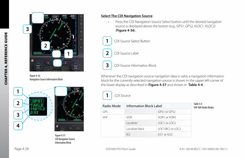
CHA
PTER
4, R
EFER
ENCE
GU
IDE
EFD1000 PFD Pilot’s GuidePage 4-28 A-01-184-00 REV C / 091-00005-001 REV ( )
Select The CDI Navigation Source
Press the CDI Navigation Source Select button until the desired navigation •source is displayed above the button (e.g., GPS1, GPS2, VLOC1, VLOC2) (Figure 4-56).
CDI Source Select Button
CDI Source Label
CDI Source Information Block
Whenever the CDI navigation source navigation data is valid, a navigation information block for the currently selected navigation source is shown in the upper left corner of the lower display as described in Figure 4-57 and shown in Table 4-4.
CDI Source
Figure 4-56 Navigation Source Information Block
Figure 4-57 CDI Navigation Source Information Block
Radio Mode Information Block Label
GPS GPS1 or GPS2
VHF VOR VOR1 or VOR2
Localizer LOC1 or LOC2
Localizer Back LOC1(BC) or LOC2
ILS ILS1 or ILS2
Table 4-4 VHF NAV Radio Modes
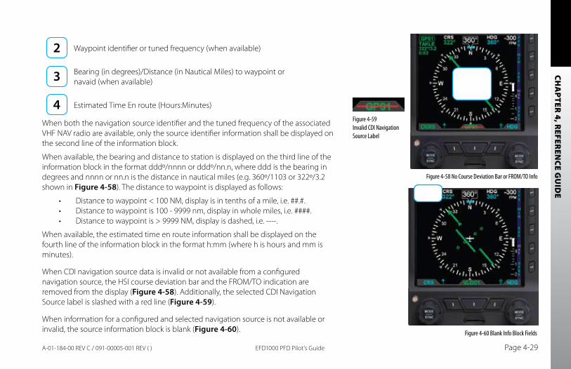
CHA
PTER 4, R
EFEREN
CE GU
IDE
EFD1000 PFD Pilot’s Guide Page 4-29A-01-184-00 REV C / 091-00005-001 REV ( )
Waypoint identifier or tuned frequency (when available)
Bearing (in degrees)/Distance (in Nautical Miles) to waypoint or navaid (when available)
Estimated Time En route (Hours:Minutes)
When both the navigation source identifier and the tuned frequency of the associated VHF NAV radio are available, only the source identifier information shall be displayed on the second line of the information block.
When available, the bearing and distance to station is displayed on the third line of the information block in the format dddº/nnnn or dddº/nn.n, where ddd is the bearing in degrees and nnnn or nn.n is the distance in nautical miles (e.g. 360º/1103 or 322º/3.2 shown in Figure 4-58). The distance to waypoint is displayed as follows:
Distance to waypoint < 100 NM, display is in tenths of a mile, i.e. ##.#.•Distance to waypoint is 100 - 9999 nm, display in whole miles, i.e. ####.•Distance to waypoint is > 9999 NM, display is dashed, i.e. ----.•
When available, the estimated time en route information shall be displayed on the fourth line of the information block in the format h:mm (where h is hours and mm is minutes).
When CDI navigation source data is invalid or not available from a configured navigation source, the HSI course deviation bar and the FROM/TO indication are removed from the display (Figure 4-58). Additionally, the selected CDI Navigation Source label is slashed with a red line (Figure 4-59).
When information for a configured and selected navigation source is not available or invalid, the source information block is blank (Figure 4-60).
Figure 4-58 No Course Deviation Bar or FROM/TO Info
Figure 4-59 Invalid CDI Navigation Source Label
Figure 4-60 Blank Info Block Fields
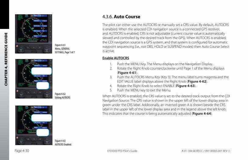
CHA
PTER
4, R
EFER
ENCE
GU
IDE
EFD1000 PFD Pilot’s GuidePage 4-30 A-01-184-00 REV C / 091-00005-001 REV ( )
4.3.6. Auto Course
The pilot can either use the AUTOCRS or manually set a CRS value. By default, AUTOCRS is enabled. When the selected CDI navigation source is a connected GPS receiver, and AUTOCRS is enabled, CRS is not adjustable (current course value is automatically slewed and controlled by the desired track from the GPS). When AUTOCRS is enabled, the CDI navigation source is a GPS system, and that system is configured for automatic waypoint sequencing (i.e., not OBS, HOLD or SUSPEND modes) then Auto Course Select is active.
Enable AUTOCRS
1. Push the MENU Key. The Menu displays on the Navigation Display.2. Rotate the Right Knob counterclockwise until Page 1 of the Menu displays
(Figure 4-61).3. Push the AUTOCRS Menu Key (Key 3). The menu label turns magenta and the
EDIT VALUE label displays above the Right Knob (Figure 4-62).4. Rotate the Right Knob to select ENABLE (Figure 4-63).5. Push the MENU key to exit the Menu.
When AUTOCRS is enabled, the CRS value is set to the desired track output from the CDI Navigation Source. The CRS value is shown in the upper left of the lower display area in green under the CRS label. Additionally, an inverted green A is shown beside the CRS label in the upper left of the lower display area and in the legend above the left knob. This indicates that the course is being automatically adjusted (Figure 4-64).
Figure 4-61 Menu, GENERAL SETTINGS, Page 1 of 7
Figure 4-62 Editing AUTOCRS
Figure 4-63 AUTOCRS Enabled
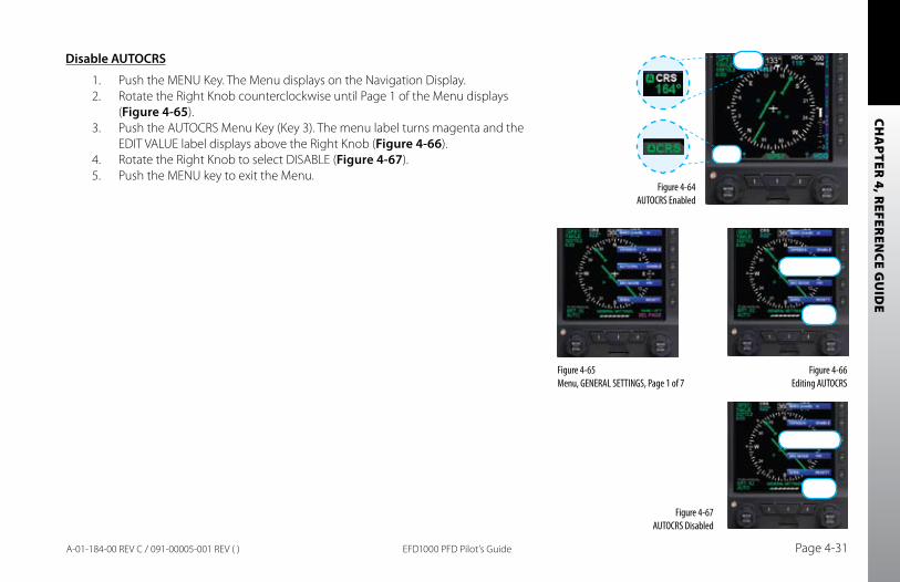
CHA
PTER 4, R
EFEREN
CE GU
IDE
EFD1000 PFD Pilot’s Guide Page 4-31A-01-184-00 REV C / 091-00005-001 REV ( )
Disable AUTOCRS
1. Push the MENU Key. The Menu displays on the Navigation Display.2. Rotate the Right Knob counterclockwise until Page 1 of the Menu displays
(Figure 4-65).3. Push the AUTOCRS Menu Key (Key 3). The menu label turns magenta and the
EDIT VALUE label displays above the Right Knob (Figure 4-66).4. Rotate the Right Knob to select DISABLE (Figure 4-67).5. Push the MENU key to exit the Menu.
Figure 4-64 AUTOCRS Enabled
Figure 4-65 Menu, GENERAL SETTINGS, Page 1 of 7
Figure 4-67 AUTOCRS Disabled
Figure 4-66 Editing AUTOCRS
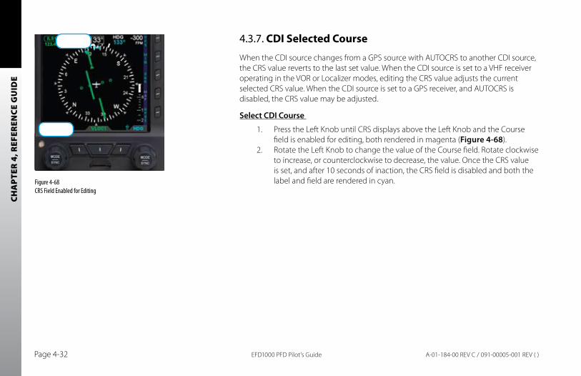
CHA
PTER
4, R
EFER
ENCE
GU
IDE
EFD1000 PFD Pilot’s GuidePage 4-32 A-01-184-00 REV C / 091-00005-001 REV ( )
4.3.7. CDI Selected Course
When the CDI source changes from a GPS source with AUTOCRS to another CDI source, the CRS value reverts to the last set value. When the CDI source is set to a VHF receiver operating in the VOR or Localizer modes, editing the CRS value adjusts the current selected CRS value. When the CDI source is set to a GPS receiver, and AUTOCRS is disabled, the CRS value may be adjusted.
Select CDI Course
1. Press the Left Knob until CRS displays above the Left Knob and the Course field is enabled for editing, both rendered in magenta (Figure 4-68).
2. Rotate the Left Knob to change the value of the Course field. Rotate clockwise to increase, or counterclockwise to decrease, the value. Once the CRS value is set, and after 10 seconds of inaction, the CRS field is disabled and both the label and field are rendered in cyan.Figure 4-68
CRS Field Enabled for Editing
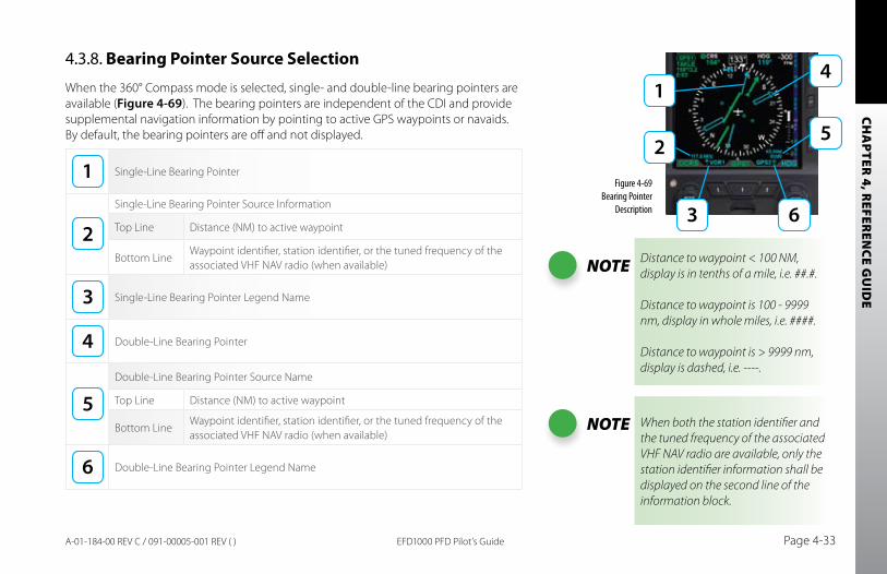
CHA
PTER 4, R
EFEREN
CE GU
IDE
EFD1000 PFD Pilot’s Guide Page 4-33A-01-184-00 REV C / 091-00005-001 REV ( )
4.3.8. Bearing Pointer Source Selection
When the 360° Compass mode is selected, single- and double-line bearing pointers are available (Figure 4-69). The bearing pointers are independent of the CDI and provide supplemental navigation information by pointing to active GPS waypoints or navaids. By default, the bearing pointers are off and not displayed.
Single-Line Bearing Pointer
Single-Line Bearing Pointer Source Information
Top Line Distance (NM) to active waypoint
Bottom LineWaypoint identifier, station identifier, or the tuned frequency of the associated VHF NAV radio (when available)
Single-Line Bearing Pointer Legend Name
Double-Line Bearing Pointer
Double-Line Bearing Pointer Source Name
Top Line Distance (NM) to active waypoint
Bottom LineWaypoint identifier, station identifier, or the tuned frequency of the associated VHF NAV radio (when available)
Double-Line Bearing Pointer Legend Name
NOTE When both the station identifier and the tuned frequency of the associated VHF NAV radio are available, only the station identifier information shall be displayed on the second line of the information block.
NOTE Distance to waypoint < 100 NM, display is in tenths of a mile, i.e. ##.#.
Distance to waypoint is 100 - 9999 nm, display in whole miles, i.e. ####.
Distance to waypoint is > 9999 nm, display is dashed, i.e. ----.
Figure 4-69 Bearing Pointer
Description
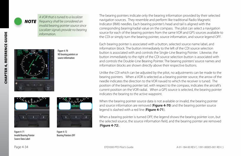
CHA
PTER
4, R
EFER
ENCE
GU
IDE
EFD1000 PFD Pilot’s GuidePage 4-34 A-01-184-00 REV C / 091-00005-001 REV ( )
The bearing pointers indicate only the bearing information provided by their selected navigation sources. They resemble and perform like traditional Radio Magnetic Indicator (RMI) needles. Each bearing pointer’s head and tail is aligned with the corresponding bearing/radial value on the compass. The pilot can select a navigation source for each of the bearing pointers from the same VOR and GPS sources available to the CDI or simply turn the bearing pointer, source information, and source legend OFF.
Each bearing pointer is associated with a button, selected source name label, and information block. The button immediately to the left of the CDI source selection button is associated with and controls the Single-Line Bearing Pointer. Likewise, the button immediately to the right of the CDI source selection button is associated with and controls the Double-Line Bearing Pointer. The bearing pointers’ source names and information blocks are shown directly above their respective buttons.
Unlike the CDI which can be adjusted by the pilot, no adjustments can be made to the bearing pointers. When a VOR is selected as a bearing pointer source, the arrow of the needle indicates the direction to the VOR navaid to which the receiver is tuned. The position of the bearing pointer tail, with respect to the compass, indicates the aircraft’s current position on the VOR radial. When a GPS source is selected, the bearing pointer indicates the bearing to the active waypoint.
When the bearing pointer source data is not available or invalid, the bearing pointer and source information are removed (Figure 4-70) and the bearing pointer source legend is slashed with a red line (Figure 4-71).
When a bearing pointer is turned OFF, the legend shows the bearing pointer icon, but the selected source, the source information field, and the bearing pointer are removed (Figure 4-72).
NOTEA VOR that is tuned to a localizer frequency shall be considered an invalid bearing pointer source since Localizer signals provide no bearing information.
Figure 4-72 Bearing Pointers OFF
Figure 4-70 NO bearing pointers or source information
Figure 4-71 Invalid Bearing Pointer Source Data Label
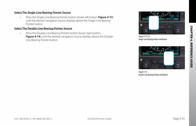
CHA
PTER 4, R
EFEREN
CE GU
IDE
EFD1000 PFD Pilot’s Guide Page 4-35A-01-184-00 REV C / 091-00005-001 REV ( )
Select The Single-Line bearing Pointer Source
Press the Single-Line Bearing Pointer button (lower left button, • Figure 4-73) until the desired navigation source displays above the Single-Line Bearing Pointer button.
Select The Double-Line bearing Pointer Source
Press the Double-Line Bearing Pointer button (lower right button, •Figure 4-74) until the desired navigation source displays above the Double-Line Bearing Pointer button.
Figure 4-73 173 Single-Line Bearing Pointer and Button
Figure 4-74 Double-Line Bearing Pointer and Button
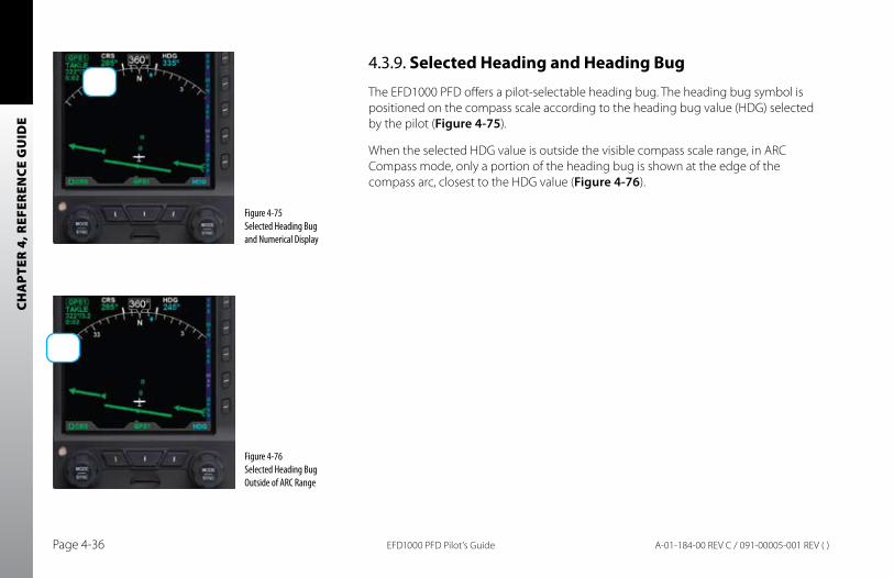
CHA
PTER
4, R
EFER
ENCE
GU
IDE
EFD1000 PFD Pilot’s GuidePage 4-36 A-01-184-00 REV C / 091-00005-001 REV ( )
4.3.9. Selected Heading and Heading Bug
The EFD1000 PFD offers a pilot-selectable heading bug. The heading bug symbol is positioned on the compass scale according to the heading bug value (HDG) selected by the pilot (Figure 4-75).
When the selected HDG value is outside the visible compass scale range, in ARC Compass mode, only a portion of the heading bug is shown at the edge of the compass arc, closest to the HDG value (Figure 4-76).
Figure 4-75 Selected Heading Bug and Numerical Display
Figure 4-76 Selected Heading Bug Outside of ARC Range
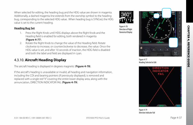
CHA
PTER 4, R
EFEREN
CE GU
IDE
EFD1000 PFD Pilot’s Guide Page 4-37A-01-184-00 REV C / 091-00005-001 REV ( )
When selected for editing, the heading bug and the HDG value are shown in magenta. Additionally, a dashed magenta line extends from the ownship symbol to the heading bug, corresponding to the selected HDG value. When heading bug is SYNCed, the HDG value is set to the current heading.
Heading bug Set
1. Press the Right Knob until HDG displays above the Right Knob and the Heading field is enabled for editing, both rendered in magenta (Figure 4-77).
2. Rotate the Right Knob to change the value of the Heading field. Rotate clockwise to increase, or counterclockwise to decrease, the value. Once the HDG value is set, and after 10 seconds of inaction, the HDG field is disabled and both the label and field are displayed in cyan.
4.3.10. Aircraft Heading Display
The aircraft heading is displayed in degrees magnetic (Figure 4-78).
If the aircraft’s heading is unavailable or invalid, all heading and navigation information, including the CDI and bearing pointers (if previously displayed), is removed and replaced with a single red “X” covering the entire lower display area, along with the annunciation, DIRECTION INDICATOR FAIL (Figure 4-79).
Figure 4-77 Heading Selected to Edit
Figure 4-78 Direction of Flight Numerical Display
Figure 4-79 Direction Indicator Fail
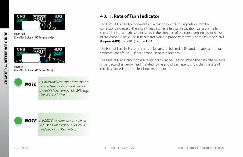
CHA
PTER
4, R
EFER
ENCE
GU
IDE
EFD1000 PFD Pilot’s GuidePage 4-38 A-01-184-00 REV C / 091-00005-001 REV ( )
4.3.11. Rate of Turn Indicator
The Rate of Turn Indicator consists of a curved white line originating from the corresponding side of the aircraft heading (i.e., a left turn indication starts on the left side of the index mark), and extends in the direction of the turn along the outer radius of the compass scale. The turn rate indication is provided for every compass mode, 360° (Figure 4-80) and ARC (Figure 4-81).
The Rate of Turn Indicator features tick marks for full and half-standard rates of turn (a standard rate of turn = 3° per second) in both directions.
The Rate of Turn Indicator has a range of 0° – 6° per second. When the turn rate exceeds 6° per second, an arrowhead is added to the end of the tape to show that the rate of turn has exceeded the limits of the instrument.
NOTE All map and flight plan elements are received from the GPS and are only available from compatible GPSs (e.g., GNS 430, GNS 530).
Figure 4-80 Rate of Turn Indicator (360° Compass Mode)
Figure 4-81 Rate of Turn Indicator (ARC Compass Mode)
NOTE A VORTAC is shown as a combined VOR and DME symbol. A TACAN is rendered as a DME symbol.
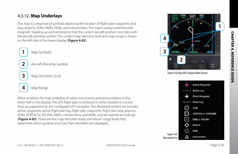
CHA
PTER 4, R
EFEREN
CE GU
IDE
EFD1000 PFD Pilot’s Guide Page 4-39A-01-184-00 REV C / 091-00005-001 REV ( )
4.3.12. Map Underlays
The map is comprised of symbols depicting the location of flight plan waypoints and legs, airports, VORs, DMEs, NDBs, and intersections. The map is always oriented with magnetic heading up and centered so that the current aircraft position coincides with the aircraft ownship symbol. The current map declutter level and map range is shown on the left side of the lower display (Figure 4-82).
Map Symbols
Aircraft Ownship Symbol
Map Declutter Level
Map Range
When enabled, the map underlies all other instruments and annunciations in the lower half of the display. The GPS flight plan is rendered in either straight or curved lines, as supported by the configured GPS navigator. The displayed symbol set includes active waypoints, active flight plan leg, flight plan waypoints, flight plan legs, airports, VORs, VORTACSs, TACANs, DMEs, intersections, and NDBs, and are layered accordingly (Figure 4-83). There are five map declutter levels and eleven range levels that determine which symbols and how their identifiers are displayed.
Figure 4-83 Map Symbol Set
Figure 4-82 Map (ARC Compass Mode Shown)
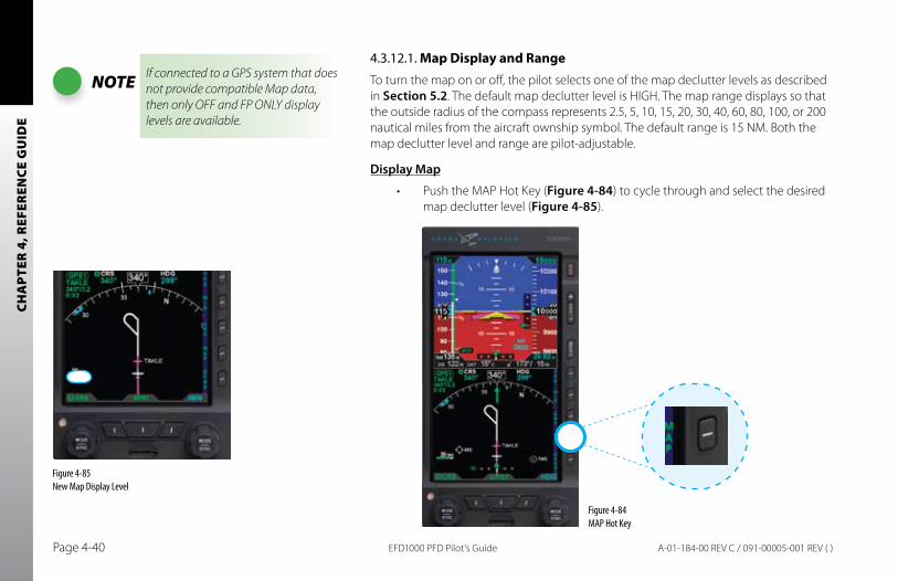
CHA
PTER
4, R
EFER
ENCE
GU
IDE
EFD1000 PFD Pilot’s GuidePage 4-40 A-01-184-00 REV C / 091-00005-001 REV ( )
4.3.12.1. Map Display and RangeTo turn the map on or off, the pilot selects one of the map declutter levels as described in Section 5.2. The default map declutter level is HIGH. The map range displays so that the outside radius of the compass represents 2.5, 5, 10, 15, 20, 30, 40, 60, 80, 100, or 200 nautical miles from the aircraft ownship symbol. The default range is 15 NM. Both the map declutter level and range are pilot-adjustable.
Display Map
Push the MAP Hot Key (• Figure 4-84) to cycle through and select the desired map declutter level (Figure 4-85).
NOTE If connected to a GPS system that does not provide compatible Map data, then only OFF and FP ONLY display levels are available.
Figure 4-84 MAP Hot Key
Figure 4-85 New Map Display Level
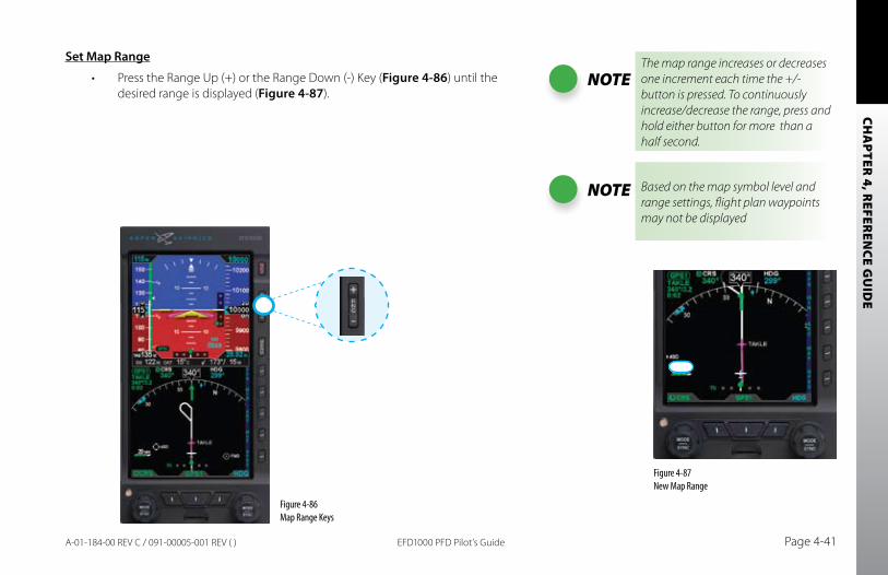
CHA
PTER 4, R
EFEREN
CE GU
IDE
EFD1000 PFD Pilot’s Guide Page 4-41A-01-184-00 REV C / 091-00005-001 REV ( )
Set Map Range
Press the Range Up (+) or the Range Down (-) Key (• Figure 4-86) until the desired range is displayed (Figure 4-87).
Figure 4-86 Map Range Keys
Figure 4-87 New Map Range
NOTEThe map range increases or decreases one increment each time the +/- button is pressed. To continuously increase/decrease the range, press and hold either button for more than a half second.
NOTE Based on the map symbol level and range settings, flight plan waypoints may not be displayed
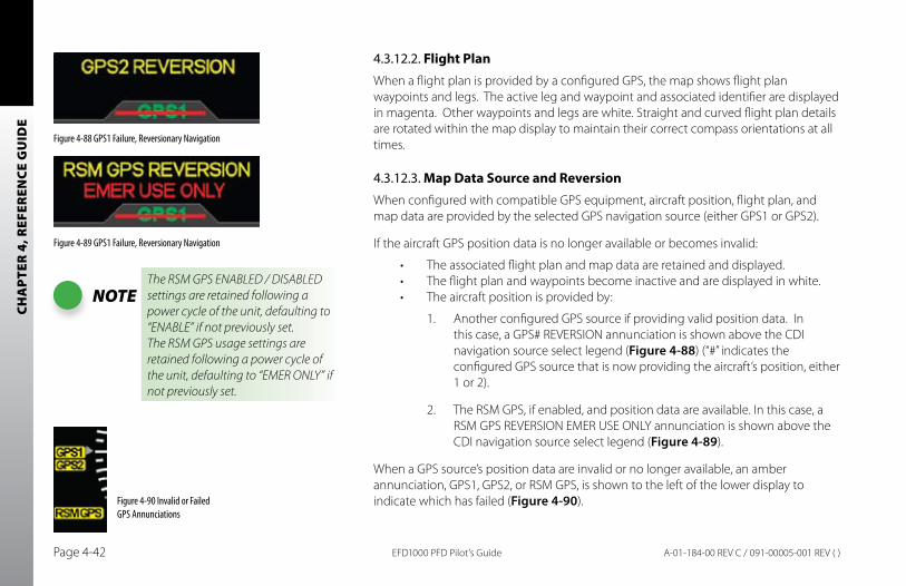
CHA
PTER
4, R
EFER
ENCE
GU
IDE
EFD1000 PFD Pilot’s GuidePage 4-42 A-01-184-00 REV C / 091-00005-001 REV ( )
4.3.12.2. Flight PlanWhen a flight plan is provided by a configured GPS, the map shows flight plan waypoints and legs. The active leg and waypoint and associated identifier are displayed in magenta. Other waypoints and legs are white. Straight and curved flight plan details are rotated within the map display to maintain their correct compass orientations at all times.
4.3.12.3. Map Data Source and ReversionWhen configured with compatible GPS equipment, aircraft position, flight plan, and map data are provided by the selected GPS navigation source (either GPS1 or GPS2).
If the aircraft GPS position data is no longer available or becomes invalid:
The associated flight plan and map data are retained and displayed. •The flight plan and waypoints become inactive and are displayed in white.•The aircraft position is provided by:•
Another configured GPS source if providing valid position data. In 1. this case, a GPS# REVERSION annunciation is shown above the CDI navigation source select legend (Figure 4-88) (“#” indicates the configured GPS source that is now providing the aircraft’s position, either 1 or 2).
The RSM GPS, if enabled, and position data are available. In this case, a 2. RSM GPS REVERSION EMER USE ONLY annunciation is shown above the CDI navigation source select legend (Figure 4-89).
When a GPS source’s position data are invalid or no longer available, an amber annunciation, GPS1, GPS2, or RSM GPS, is shown to the left of the lower display to indicate which has failed (Figure 4-90).
NOTEThe RSM GPS ENABLED / DISABLED settings are retained following a power cycle of the unit, defaulting to “ENABLE” if not previously set.The RSM GPS usage settings are retained following a power cycle of the unit, defaulting to “EMER ONLY” if not previously set.
Figure 4-88 GPS1 Failure, Reversionary Navigation
Figure 4-89 GPS1 Failure, Reversionary Navigation
Figure 4-90 Invalid or Failed GPS Annunciations
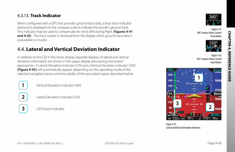
CHA
PTER 4, R
EFEREN
CE GU
IDE
EFD1000 PFD Pilot’s Guide Page 4-43A-01-184-00 REV C / 091-00005-001 REV ( )
4.3.13. Track Indicator
When configured with a GPS that provides ground track data, a blue track indicator diamond is displayed on the compass scale to indicate the aircraft’s ground track. This indicator may be used to compensate for wind drift during flight (Figures 4-91 and 4-92). The track marker is removed from the display when ground track data is unavailable or invalid.
4.4. Lateral and Vertical Deviation IndicatorIn addition to the CDI in the lower display, separate displays of lateral and vertical deviation information are shown in the upper display area during instrument approaches. A Lateral Deviation Indicator (LDI) and a Vertical Deviation Indicator (VDI) (Figure 4-93) will automatically appear, depending on the operating mode of the selected navigation sensor and the validity of the associated signal, described below.
Vertical Deviation Indicator (VDI)
Lateral Deviation Indicator (LDI)
LDI Source Indicator
Figure 4-91 ARC Compass Mode, Ground
Track Marker
Figure 4-92 360° Compass Mode, Ground
Track Marker
Figure 4-93 Lateral and Vertical Deviation Indicators
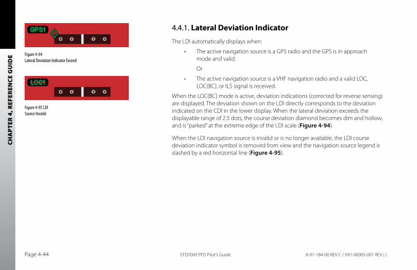
CHA
PTER
4, R
EFER
ENCE
GU
IDE
EFD1000 PFD Pilot’s GuidePage 4-44 A-01-184-00 REV C / 091-00005-001 REV ( )
4.4.1. Lateral Deviation Indicator
The LDI automatically displays when:
The active navigation source is a GPS radio and the GPS is in approach •mode and valid.
Or
The active navigation source is a VHF navigation radio and a valid LOC, •LOC(BC), or ILS signal is received.
When the LOC(BC) mode is active, deviation indications (corrected for reverse sensing) are displayed. The deviation shown on the LDI directly corresponds to the deviation indicated on the CDI in the lower display. When the lateral deviation exceeds the displayable range of 2.5 dots, the course deviation diamond becomes dim and hollow, and is “parked” at the extreme edge of the LDI scale (Figure 4-94).
When the LDI navigation source is invalid or is no longer available, the LDI course deviation indicator symbol is removed from view and the navigation source legend is slashed by a red horizontal line (Figure 4-95).
Figure 4-94 Lateral Deviation Indicator Exceed
Figure 4-95 LDI Source Invalid
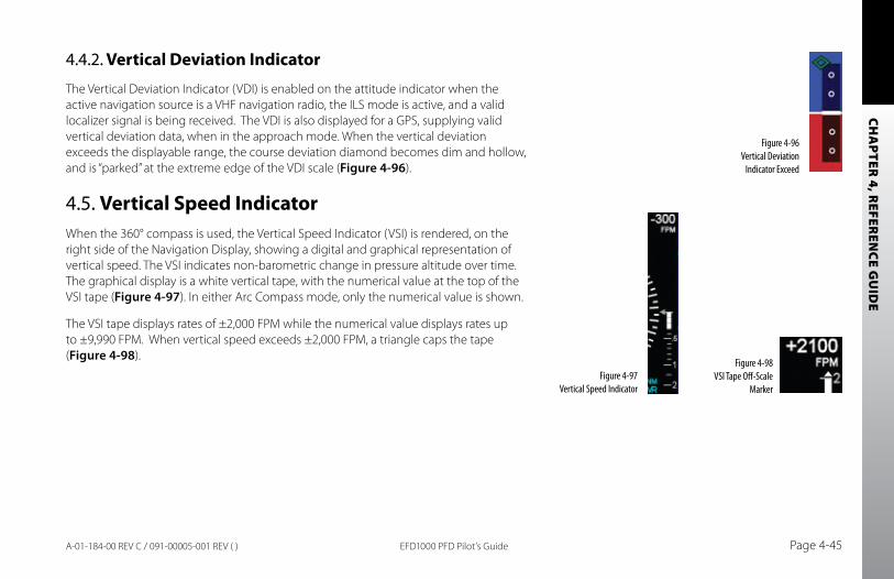
CHA
PTER 4, R
EFEREN
CE GU
IDE
EFD1000 PFD Pilot’s Guide Page 4-45A-01-184-00 REV C / 091-00005-001 REV ( )
4.4.2. Vertical Deviation Indicator
The Vertical Deviation Indicator (VDI) is enabled on the attitude indicator when the active navigation source is a VHF navigation radio, the ILS mode is active, and a valid localizer signal is being received. The VDI is also displayed for a GPS, supplying valid vertical deviation data, when in the approach mode. When the vertical deviation exceeds the displayable range, the course deviation diamond becomes dim and hollow, and is “parked” at the extreme edge of the VDI scale (Figure 4-96).
4.5. Vertical Speed IndicatorWhen the 360° compass is used, the Vertical Speed Indicator (VSI) is rendered, on the right side of the Navigation Display, showing a digital and graphical representation of vertical speed. The VSI indicates non-barometric change in pressure altitude over time. The graphical display is a white vertical tape, with the numerical value at the top of the VSI tape (Figure 4-97). In either Arc Compass mode, only the numerical value is shown.
The VSI tape displays rates of ±2,000 FPM while the numerical value displays rates up to ±9,990 FPM. When vertical speed exceeds ±2,000 FPM, a triangle caps the tape (Figure 4-98).
Figure 4-96 Vertical Deviation
Indicator Exceed
Figure 4-98 VSI Tape Off-Scale
MarkerFigure 4-97
Vertical Speed Indicator
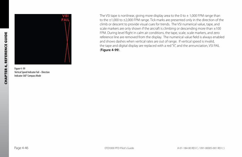
CHA
PTER
4, R
EFER
ENCE
GU
IDE
EFD1000 PFD Pilot’s GuidePage 4-46 A-01-184-00 REV C / 091-00005-001 REV ( )
The VSI tape is nonlinear, giving more display area to the 0 to ± 1,000 FPM range than to the ±1,000 to ±2,000 FPM range. Tick marks are presented only in the direction of the climb or descent to provide visual cues for trends. The VSI numerical value, tape, and scale markers are only shown if the aircraft is climbing or descending more than ±100 FPM. During level flight in calm air conditions, the tape, scale, scale markers, and zero reference line are removed from the display. The numerical value field is always enabled and shows dashes when vertical rates are out of range. If vertical speed is invalid, the tape and digital display are replaced with a red “X”, and the annunciation, VSI FAIL (Figure 4-99).
Figure 4 -99 Vertical Speed Indicator Fail – Direction Indicator 360° Compass Mode
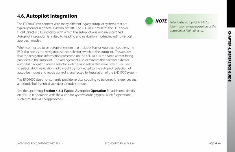
CHA
PTER 4, R
EFEREN
CE GU
IDE
EFD1000 PFD Pilot’s Guide Page 4-47A-01-184-00 REV C / 091-00005-001 REV ( )
4.6. Autopilot IntegrationThe EFD1000 can connect with many different legacy autopilot systems that are typically found in general aviation aircraft. The EFD1000 emulates the HSI and/or Flight Director (FD) indicator with which the autopilot was originally certified. Autopilot integration is limited to heading and navigation modes, including vertical approach modes.
When connected to an autopilot system that includes Nav or Approach couplers, the EFD also acts as the navigation source selector switch to the autopilot. This assures that the navigation information presented on the EFD1000 is the same as that being provided to the autopilot. This arrangement also eliminates the need for external autopilot navigation source selector switches and relays that were previously used to select which navigation radio would be connected to the autopilot. Selection of autopilot modes and mode control is unaffected by installation of the EFD1000 system.
The EFD1000 does not currently provide vertical coupling to barometric references such as altitude hold, vertical speed, or altitude capture.
See the upcoming Section 4.6.3 Typical Autopilot Operation for additional details on EFD1000 operation with the autopilot systems during typical aircraft operations, such as VOR/ILS/GPS approaches.
NOTE Refer to the autopilot AFMS for information on the operation of the autopilot or flight director.
CHA
PTER
4, R
EFER
ENCE
GU
IDE
EFD1000 PFD Pilot’s GuidePage 4-48 A-01-184-00 REV C / 091-00005-001 REV ( )
4.6.1. GPS Steering (GPSS)
GPS Steering represents a modernized approach to flying between flight plan waypoints, and offers many advantages of over traditional methods of flying direct course lines between waypoints.
With traditional point-to-point navigation, the autopilot is provided with desired course and cross-tack deviation information associated with the current flight leg. From there, it will maneuver the aircraft to center the needle and track the desired course. The autopilot does not anticipate upcoming course changes, nor can it fly curved flight paths without pilot assistance, and it has to recompute wind corrections following each course change. Upon reaching a waypoint, the pilot must set the course for the next leg (unless Auto Course Select is enabled, see Section 4.3.6), and the autopilot will then intercept and track that leg. In this type of operation, the CDI must always be set to the current desired navigation course.
With GPS Steering, the EFD1000 can unlock the GPS Steering capability already available in many models of General Aviation GPS computers. In GPS systems with this capability, the GPS continually computes the desired bank angle to track the GPS flight plan, and outputs that information over an ARINC 429 data bus. The GPS Steering command includes anticipation of upcoming turns; this includes the turn rate and turn initiation point required to roll out centered on the next leg, with the deviation needle centered.
Some GPS systems, such as the Garmin 4xx/5xxW series of WAAS navigators, even provide GPS Steering commands for complex procedures, such as DME arcs, holding patterns, procedure turns, etc., allowing the autopilot to fly these maneuvers without pilot input. Check with your GPS manufacturer to see if your GPS supports these capabilities.
The EFD1000 translates GPS Steering commands received over an ARINC 429 bus into a signal that is compatible with the autopilot Heading channel. Thus, by selecting GPSS
NOTEWhen GPSS is selected on the EFD1000, the autopilot must be in Heading mode to follow the GPSS command. The GPSS feature requires installation of the optional ACU.
NOTERefer to the Aircraft Flight Manual Supplement for your GPS system for information about GPSS steering commands that may be output by that system.
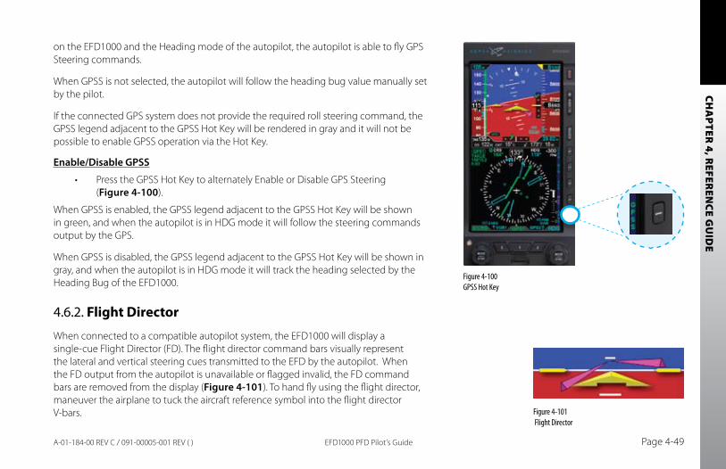
CHA
PTER 4, R
EFEREN
CE GU
IDE
EFD1000 PFD Pilot’s Guide Page 4-49A-01-184-00 REV C / 091-00005-001 REV ( )
on the EFD1000 and the Heading mode of the autopilot, the autopilot is able to fly GPS Steering commands.
When GPSS is not selected, the autopilot will follow the heading bug value manually set by the pilot.
If the connected GPS system does not provide the required roll steering command, the GPSS legend adjacent to the GPSS Hot Key will be rendered in gray and it will not be possible to enable GPSS operation via the Hot Key.
Enable/Disable GPSS
Press the GPSS Hot Key to alternately Enable or Disable GPS Steering• (Figure 4-100).
When GPSS is enabled, the GPSS legend adjacent to the GPSS Hot Key will be shown in green, and when the autopilot is in HDG mode it will follow the steering commands output by the GPS.
When GPSS is disabled, the GPSS legend adjacent to the GPSS Hot Key will be shown in gray, and when the autopilot is in HDG mode it will track the heading selected by the Heading Bug of the EFD1000.
4.6.2. Flight Director
When connected to a compatible autopilot system, the EFD1000 will display a single-cue Flight Director (FD). The flight director command bars visually represent the lateral and vertical steering cues transmitted to the EFD by the autopilot. When the FD output from the autopilot is unavailable or flagged invalid, the FD command bars are removed from the display (Figure 4-101). To hand fly using the flight director, maneuver the airplane to tuck the aircraft reference symbol into the flight director V-bars.
Figure 4-100 GPSS Hot Key
Figure 4-101 Flight Director
CHA
PTER
4, R
EFER
ENCE
GU
IDE
EFD1000 PFD Pilot’s GuidePage 4-50 A-01-184-00 REV C / 091-00005-001 REV ( )
4.6.3. Typical Autopilot Operations
Whenever the EFD1000 installed configuration includes connections to GPS, VLOC and autopilot systems, the EFD1000 acts as a conduit of data between the navigation radios and the autopilot system. This configuration enables any navigation sensor available for display on the EFD system to be coupled to the autopilot.
NOTERefer to the autopilot system Aircraft Flight Manual Supplement and/or POH for details regarding use and operation of the autopilot system.
Examples here are provided for reference only, based on operation of the Bendix/King KFC-200 autopilot, and actual operation may vary depending on the autopilot system installed in your aircraft.
It is your responsibility as Pilot in Command to ensure that you are conversant with the operation of all installed equipment. Operation of the EFD1000 system in IMC conditions should not be undertaken unless you are proficient in its use and operation, as described herein.
NOTE The autopilot must be in Heading (HDG) Mode to receive GPSS signals from the EFD1000.
NOTEWhen using an integrated VLOC/GPS radio system, select the VLOC or GPS portion of the integrated radio by pressing the CDI source key on the GPS select until the desired source is indicated above the EFD1000 CDI (Section 4.3.5) Source Select button.
NOTEWhen GPSS is enabled on the EFD1000, the HSI heading bug is not coupled to the autopilot. To connect the heading bug to the autopilot, disable GPSS via the GPSS Hot Key.
CHA
PTER 4, R
EFEREN
CE GU
IDE
EFD1000 PFD Pilot’s Guide Page 4-51A-01-184-00 REV C / 091-00005-001 REV ( )
“HDG” Mode Operation – Heading bug Steering
1. Set the heading bug on the EFD1000 to the desired heading (Section 4.3.9).2. Verify that GPSS is not selected (GPSS Legend on Hot Keys shown in GRAY).3. Select the autopilot’s HDG mode. 4. Engage the autopilot.5. Verify that the autopilot turns the aircraft to the selected heading.
“HDG” Mode Operation – GPS Steering (GPSS)
1. Couple the EFD1000 CDI to a GPS sensor navigation source with an active flight plan.
2. Enable GPSS by pressing the GPSS Hot Key so that GPSS is rendered in GREEN.3. Select the autopilot’s HDG mode.4. Engage the autopilot.5. Verify that the autopilot turns the aircraft to follow the GPS flight plan.
“NAV” Mode Operation – VLOC Navigation
1. Using the CDI Nav Source Select button, couple a tuned/valid VLOC radio to the CDI and set the desired course (Section 4.3.7).
2. Set the EFD1000 heading bug (Section 4.3.9) to a value that will intercept the desired course.
3. Engage the autopilot in heading mode and verify that the aircraft turns to the desired heading.
4. Arm NAV capture on the autopilot by selecting its NAV mode.5. Monitor the CDI deflection and verify that, upon intercepting the desired
course, the autopilot switches to NAV capture, and turns to track the desired course.
NOTENot all autopilots operate in the manner described here for intercepting courses. See the AFMS for your autopilot installation to understand how to adapt these example procedures to your particular autopilot.
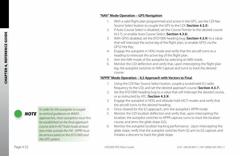
CHA
PTER
4, R
EFER
ENCE
GU
IDE
EFD1000 PFD Pilot’s GuidePage 4-52 A-01-184-00 REV C / 091-00005-001 REV ( )
“NAV” Mode Operation – GPS Navigation
1. With a valid flight plan programmed and active in the GPS, use the CDI Nav Source Select button to couple the GPS to the CDI (Section 4.3.5).
2. If Auto Course Select is disabled, set the Course Pointer to the desired course (4.3.7), or enable Auto Course Select (Section 4.3.6).
3. With GPSS disabled, set the EFD1000 heading bug (Section 4.3.9) to a value that will intercept the active leg of the flight plan, or enable GPSS via the GPSS Hot Key.
4. Engage the autopilot in HDG mode and verify that the aircraft turns to a heading to intercept the active leg of the flight plan.
5. Arm the NAV mode of the autopilot by selecting its NAV mode.6. Monitor the CDI deflection and verify that, upon intercepting the flight plan
leg, the autopilot switches to NAV Capture and turns to track the desired course.
“APPR” Mode Operation – ILS Approach with Vectors to Final
1. Using the CDI Nav Source Select button, couple a tuned/valid ILS radio frequency to the CDI, and set the desired approach course (Section 4.3.7).
2. Set the EFD1000 heading bug to a value that will intercept the desired course, or as instructed by ATC (Section 4.3.9).
3. Engage the autopilot in HDG and altitude hold (ALT) modes and verify that the aircraft turns to the desired heading.
4. Once cleared for the ILS approach, arm the autopilot’s APPR mode.5. Monitor the CDI localizer deflection and verify that, upon intercepting the
localizer, the autopilot switches to APPR capture, turns to track the localizer course, and arms the glide slope (GS).
6. Monitor the autopilot localizer tracking performance. Upon intercepting the glide slope, verify that the autopilot switches from GS arm to GS capture, and initiates a descent to track the glide slope.
NOTEIn order for the autopilot to couple to vertical guidance on WAAS approaches, most autopilots must first be established on the final approach course and in ALT hold mode at least two miles outside the FAF. APPR must be annunciated on the EFD1000 and the GPS system.
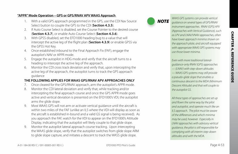
CHA
PTER 4, R
EFEREN
CE GU
IDE
EFD1000 PFD Pilot’s Guide Page 4-53A-01-184-00 REV C / 091-00005-001 REV ( )
“APPR” Mode Operation – GPS or GPS/RNAV APV WAAS Approach
1. With a valid GPS approach programmed in the GPS, use the CDI Nav Source Select button to couple the GPS to the CDI (Section 4.3.5).
2. If Auto Course Select is disabled, set the Course Pointer to the desired course (Section 4.3.7), or enable Auto Course Select (Section 4.3.6).
3. With GPSS disabled, set the EFD1000 heading bug to a value that will intercept the active leg of the flight plan (Section 4.3.9) or enable GPSS via the GPSS Hot Key.
4. Once established inbound to the Final Approach Fix (FAF), engage the autopilot’s NAV or APPR mode.
5. Engage the autopilot in HDG mode and verify that the aircraft turns to a heading to intercept the active leg of the approach.
6. Monitor the CDI cross track deviation and verify that, upon intercepting the active leg of the approach, the autopilot turns to track the GPS approach guidance
THE FOLLOWING APPLIES FOR WAAS GPS/RNAV APV APPROACHES ONLY7. Once cleared for the GPS/RNAV approach, arm the autopilot’s APPR mode.8. Monitor the CDI lateral deviation and verify that, while tracking and/or
intercepting the final approach course and once the GPS APPR mode goes active and vertical deviation is presented on the EFD1000’s VDI, the autopilot arms the glide slope.
9. Most WAAS GPS will not arm or activate vertical guidance until the aircraft is within two miles of the FAF (unlike an ILS where the VDI will display as soon as the aircraft is established in-bound and a valid GS signal is being received). As you approach the FAF, watch for the VDI to appear on the EFD1000’s Attitude Display, indicating that the autopilot will likely couple to that glide slope.
9. Monitor the autopilot lateral approach course tracking. Upon intercepting the WAAS glide slope, verify that the autopilot switches from glide slope ARM to glide slope capture, and initiates a descent to track the WASS glide slope.
NOTEWAAS GPS systems can provide vertical guidance on several types of GPS/RNAV instrument approaches. RNAV (GPS) APV (Approaches with Vertical Guidance), such as LPV and LNAV/VNAV approaches, often have lower approach minima shown on the approach plate, and aircraft equipped with appropriate WAAS GPS systems may use those lower minima.
Even with more traditional lateral-guidance-only RNAV (GPS) approaches — (LNAV) with step-down altitudes — WAAS GPS systems may still provide a pseudo-glide slope that enables a continuous descent to the MDA (Minimum Descent Altitude) and that will couple to the autopilot GS.
All these types of approaches are set up and flown the same way by the pilot and autopilot, and operate much like an ILS approach. The pilot must be aware of the differences and which minima may be used, however. Especially in LNAV approaches with advisory vertical guidance, the pilot is still responsible for complying with all interim step-down altitudes and with the MDA.
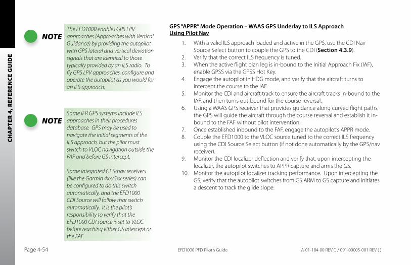
CHA
PTER
4, R
EFER
ENCE
GU
IDE
EFD1000 PFD Pilot’s GuidePage 4-54 A-01-184-00 REV C / 091-00005-001 REV ( )
GPS “APPR” Mode Operation – WAAS GPS Underlay to ILS Approach Using Pilot Nav
1. With a valid ILS approach loaded and active in the GPS, use the CDI Nav Source Select button to couple the GPS to the CDI (Section 4.3.9).
2. Verify that the correct ILS frequency is tuned.3. When the active flight plan leg is in-bound to the Initial Approach Fix (IAF),
enable GPSS via the GPSS Hot Key. 4. Engage the autopilot in HDG mode, and verify that the aircraft turns to
intercept the course to the IAF. 5. Monitor the CDI and aircraft track to ensure the aircraft tracks in-bound to the
IAF, and then turns out-bound for the course reversal.6. Using a WAAS GPS receiver that provides guidance along curved flight paths,
the GPS will guide the aircraft through the course reversal and establish it in-bound to the FAF without pilot intervention.
7. Once established inbound to the FAF, engage the autopilot’s APPR mode. 8. Couple the EFD1000 to the VLOC source tuned to the correct ILS frequency
using the CDI Source Select button (if not done automatically by the GPS/nav receiver).
9. Monitor the CDI localizer deflection and verify that, upon intercepting the localizer, the autopilot switches to APPR capture and arms the GS.
10. Monitor the autopilot localizer tracking performance. Upon intercepting the GS, verify that the autopilot switches from GS ARM to GS capture and initiates a descent to track the glide slope.
NOTEThe EFD1000 enables GPS LPV approaches (Approaches with Vertical Guidance) by providing the autopilot with GPS lateral and vertical deviation signals that are identical to those typically provided by an ILS radio. To fly GPS LPV approaches, configure and operate the autopilot as you would for an ILS approach.
NOTESome IFR GPS systems include ILS approaches in their procedures database. GPS may be used to navigate the initial segments of the ILS approach, but the pilot must switch to VLOC navigation outside the FAF and before GS intercept.
Some integrated GPS/nav receivers (like the Garmin 4xx/5xx series) can be configured to do this switch automatically, and the EFD1000 CDI Source will follow that switch automatically. It is the pilot’s responsibility to verify that the EFD1000 CDI source is set to VLOC before reaching either GS intercept or the FAF.
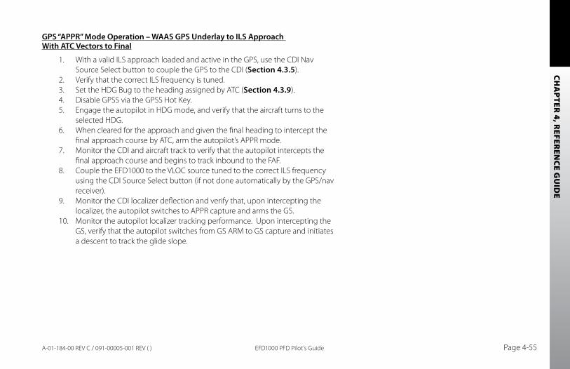
CHA
PTER 4, R
EFEREN
CE GU
IDE
EFD1000 PFD Pilot’s Guide Page 4-55A-01-184-00 REV C / 091-00005-001 REV ( )
GPS “APPR” Mode Operation – WAAS GPS Underlay to ILS Approach With ATC Vectors to Final
1. With a valid ILS approach loaded and active in the GPS, use the CDI Nav Source Select button to couple the GPS to the CDI (Section 4.3.5).
2. Verify that the correct ILS frequency is tuned.3. Set the HDG Bug to the heading assigned by ATC (Section 4.3.9).4. Disable GPSS via the GPSS Hot Key.5. Engage the autopilot in HDG mode, and verify that the aircraft turns to the
selected HDG.6. When cleared for the approach and given the final heading to intercept the
final approach course by ATC, arm the autopilot’s APPR mode.7. Monitor the CDI and aircraft track to verify that the autopilot intercepts the
final approach course and begins to track inbound to the FAF.8. Couple the EFD1000 to the VLOC source tuned to the correct ILS frequency
using the CDI Source Select button (if not done automatically by the GPS/nav receiver).
9. Monitor the CDI localizer deflection and verify that, upon intercepting the localizer, the autopilot switches to APPR capture and arms the GS.
10. Monitor the autopilot localizer tracking performance. Upon intercepting the GS, verify that the autopilot switches from GS ARM to GS capture and initiates a descent to track the glide slope.

CHA
PTER
4, R
EFER
ENCE
GU
IDE
EFD1000 PFD Pilot’s GuidePage 4-56 A-01-184-00 REV C / 091-00005-001 REV ( )
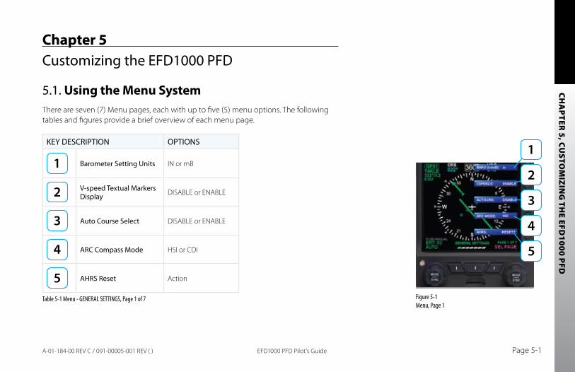
CHA
PTER 5, CU
STOM
IZING
THE EFD
1000 PFD
EFD1000 PFD Pilot’s Guide Page 5-1A-01-184-00 REV C / 091-00005-001 REV ( )
Chapter 5Customizing the EFD1000 PFD
5.1. Using the Menu SystemThere are seven (7) Menu pages, each with up to five (5) menu options. The following tables and figures provide a brief overview of each menu page.
KEY DESCRIPTION OPTIONS
Barometer Setting Units IN or mB
V-speed Textual Markers Display DISABLE or ENABLE
Auto Course Select DISABLE or ENABLE
ARC Compass Mode HSI or CDI
AHRS Reset Action
Table 5-1 Menu - GENERAL SETTINGS, Page 1 of 7 Figure 5-1 Menu, Page 1
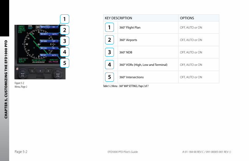
CHA
PTER
5, C
UST
OM
IZIN
G T
HE
EFD
1000
PFD
EFD1000 PFD Pilot’s GuidePage 5-2 A-01-184-00 REV C / 091-00005-001 REV ( )
KEY DESCRIPTION OPTIONS
360° Flight Plan OFF, AUTO or ON
360° Airports OFF, AUTO or ON
360° NDB OFF, AUTO or ON
360° VORs (High, Low and Terminal) OFF, AUTO or ON
360° Intersections OFF, AUTO or ON
Table 5-2 Menu - 360° MAP SETTINGS, Page 2 of 7Figure 5-2 Menu, Page 2
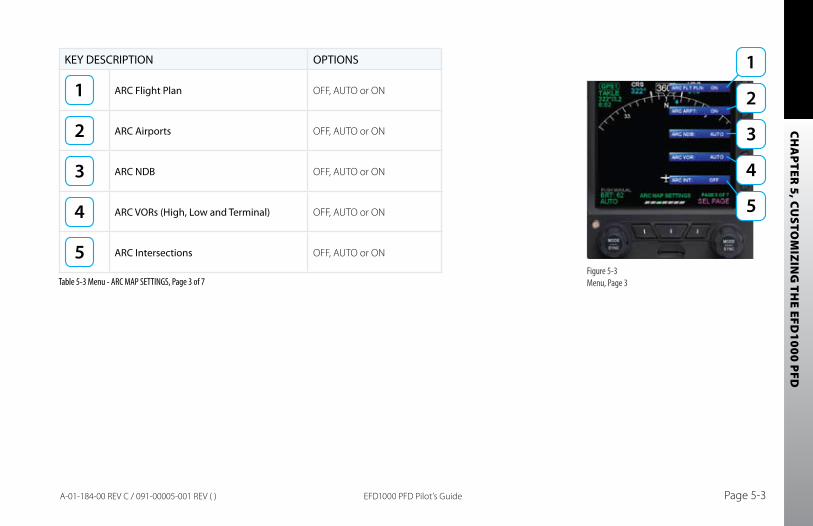
CHA
PTER 5, CU
STOM
IZING
THE EFD
1000 PFD
EFD1000 PFD Pilot’s Guide Page 5-3A-01-184-00 REV C / 091-00005-001 REV ( )
KEY DESCRIPTION OPTIONS
ARC Flight Plan OFF, AUTO or ON
ARC Airports OFF, AUTO or ON
ARC NDB OFF, AUTO or ON
ARC VORs (High, Low and Terminal) OFF, AUTO or ON
ARC Intersections OFF, AUTO or ON
Table 5-3 Menu - ARC MAP SETTINGS, Page 3 of 7Figure 5-3 Menu, Page 3
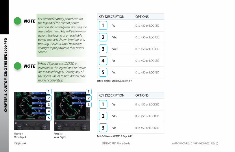
CHA
PTER
5, C
UST
OM
IZIN
G T
HE
EFD
1000
PFD
EFD1000 PFD Pilot’s GuidePage 5-4 A-01-184-00 REV C / 091-00005-001 REV ( )
NOTE For external/battery power control, the legend of the current power source is shown in green; pressing the associated menu key will perform no action. The legend of an available power source is shown in white, and pressing the associated menu key changes input power to that power source.
KEY DESCRIPTION OPTIONS
Va 0 to 450 or LOCKED
Vbg 0 to 450 or LOCKED
Vref 0 to 450 or LOCKED
Vr 0 to 450 or LOCKED
Vx 0 to 450 or LOCKED
Table 5-4 Menu - VSPEEDS A, Page 4 of 7
KEY DESCRIPTION OPTIONS
Vy 0 to 450 or LOCKED
Vlo 0 to 450 or LOCKED
Vle 0 to 450 or LOCKED
Table 5-5 Menu – VSPEEDS B, Page 5 of 7Figure 5-4 Menu, Page 4
Figure 5-5 Menu, Page 5
NOTE When V Speeds are LOCKED at installation the legend and set Value are rendered in gray. Setting any of the above values to zero disables the marker completely.
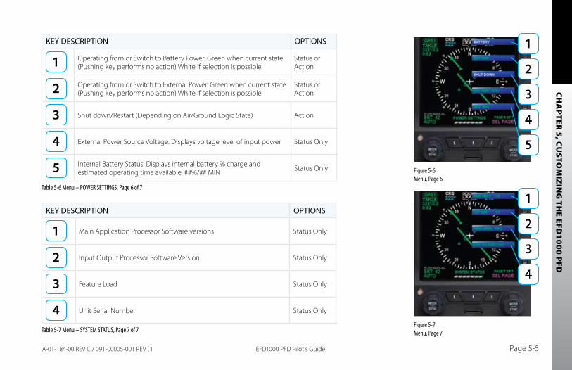
CHA
PTER 5, CU
STOM
IZING
THE EFD
1000 PFD
EFD1000 PFD Pilot’s Guide Page 5-5A-01-184-00 REV C / 091-00005-001 REV ( )
KEY DESCRIPTION OPTIONS
Operating from or Switch to Battery Power. Green when current state (Pushing key performs no action) White if selection is possible
Status or Action
Operating from or Switch to External Power. Green when current state (Pushing key performs no action) White if selection is possible
Status or Action
Shut down/Restart (Depending on Air/Ground Logic State) Action
External Power Source Voltage. Displays voltage level of input power Status Only
Internal Battery Status. Displays internal battery % charge and estimated operating time available, ##%/## MIN Status Only
Table 5-6 Menu – POWER SETTINGS, Page 6 of 7
KEY DESCRIPTION OPTIONS
Main Application Processor Software versions Status Only
Input Output Processor Software Version Status Only
Feature Load Status Only
Unit Serial Number Status Only
Table 5-7 Menu – SYSTEM STATUS, Page 7 of 7
Figure 5-6 Menu, Page 6
Figure 5-7 Menu, Page 7
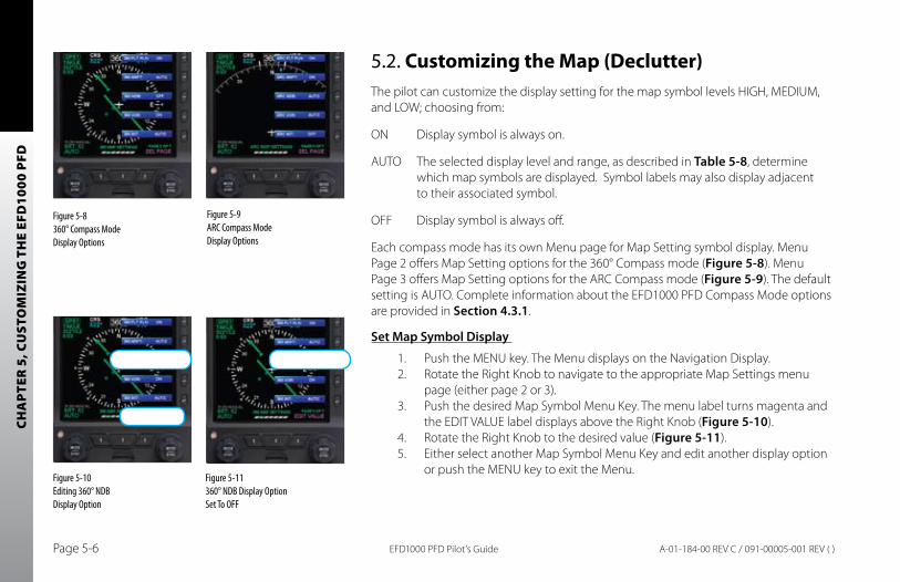
CHA
PTER
5, C
UST
OM
IZIN
G T
HE
EFD
1000
PFD
EFD1000 PFD Pilot’s GuidePage 5-6 A-01-184-00 REV C / 091-00005-001 REV ( )
5.2. Customizing the Map (Declutter)The pilot can customize the display setting for the map symbol levels HIGH, MEDIUM, and LOW; choosing from:
ON Display symbol is always on.
AUTO The selected display level and range, as described in Table 5-8, determine which map symbols are displayed. Symbol labels may also display adjacent to their associated symbol.
OFF Display symbol is always off.
Each compass mode has its own Menu page for Map Setting symbol display. Menu Page 2 offers Map Setting options for the 360° Compass mode (Figure 5-8). Menu Page 3 offers Map Setting options for the ARC Compass mode (Figure 5-9). The default setting is AUTO. Complete information about the EFD1000 PFD Compass Mode options are provided in Section 4.3.1.
Set Map Symbol Display
1. Push the MENU key. The Menu displays on the Navigation Display.2. Rotate the Right Knob to navigate to the appropriate Map Settings menu
page (either page 2 or 3).3. Push the desired Map Symbol Menu Key. The menu label turns magenta and
the EDIT VALUE label displays above the Right Knob (Figure 5-10).4. Rotate the Right Knob to the desired value (Figure 5-11).5. Either select another Map Symbol Menu Key and edit another display option
or push the MENU key to exit the Menu.
Figure 5-8 360° Compass Mode Display Options
Figure 5-9 ARC Compass Mode Display Options
Figure 5-10 Editing 360° NDB Display Option
Figure 5-11 360° NDB Display Option Set To OFF
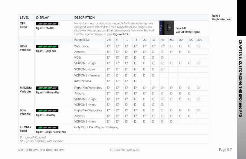
CHA
PTER 5, CU
STOM
IZING
THE EFD
1000 PFD
EFD1000 PFD Pilot’s Guide Page 5-7A-01-184-00 REV C / 091-00005-001 REV ( )
LEVEL DISPLAY DESCRIPTION
OFF Fixed Figure 5-12 No Map
No symbols, legs, or waypoints - regardless of selected range - are displayed. When selected, the map symbol level and range icons display for two seconds and then are removed from view. The MAP Hot Key legend displays in gray (Figure 5-17).
Range (NM) 2.5 5 10 15 20 30 40 60 80 100 200
HIGH Variable Figure 5-13 High Map
Waypoints D* D* D* D* D* D* D* D D D D
Airports D* D* D* D* D* D D D D D
NDBs D* D* D* D D D D
VOR/DME - High D* D* D* D D D D D D D D
VOR/DME - Low D* D* D* D D D D
VOR/DME - Terminal D* D* D* D D D
Intersections D* D* D* D
MEDIUM Variable Figure 5-14 Medium Map
Flight Plan Waypoints D* D* D* D* D* D* D* D D D D
Airports D* D* D* D* D* D D D D D
VOR/DME - High D* D* D* D D D D D D D D
VOR/DME - High D* D* D* D D D D
LOW Variable Figure 5-15 Low Map
Flight Plan Waypoints D* D* D* D* D D D D D D D
Airports D* D* D* D* D* D D D D D
VOR/DME - High D* D* D* D D D D D
FP ONLY Fixed Figure 5-16 Flight Plan Only Map
Only Flight Plan Waypoints display.
D – symbol displayed D* - symbol displayed with identifier
Figure 5-17 Map “OFF” Hot Key Legend
Table 5-8 Map Declutter Levels
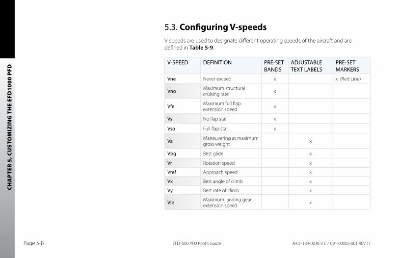
CHA
PTER
5, C
UST
OM
IZIN
G T
HE
EFD
1000
PFD
EFD1000 PFD Pilot’s GuidePage 5-8 A-01-184-00 REV C / 091-00005-001 REV ( )
5.3. Configuring V-speedsV-speeds are used to designate different operating speeds of the aircraft and are defined in Table 5-9.
V-SPEED DEFINITION PRE-SET BANDS
ADJUSTABLE TEXT LABELS
PRE-SET MARKERS
Vne Never exceed x x (Red Line)
Vno Maximum structural cruising rate x
Vfe Maximum full flap extension speed x
Vs No flap stall x
Vso Full flap stall x
Va Maneuvering at maximum gross weight x
Vbg Best glide x
Vr Rotation speed x
Vref Approach speed x
Vx Best angle of climb x
Vy Best rate of climb x
Vle Maximum landing gear extension speed x
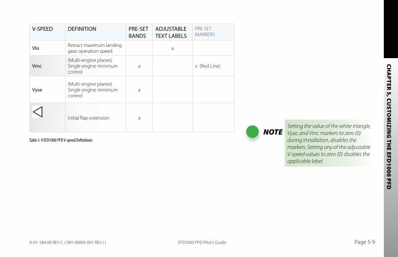
CHA
PTER 5, CU
STOM
IZING
THE EFD
1000 PFD
EFD1000 PFD Pilot’s Guide Page 5-9A-01-184-00 REV C / 091-00005-001 REV ( )
V-SPEED DEFINITION PRE-SET BANDS
ADJUSTABLE TEXT LABELS
PRE-SET MARKERS
Vlo Retract maximum landing gear operation speed x
Vmc(Multi-engine planes) Single engine minimum control
x x (Red Line)
Vyse(Multi-engine planes) Single engine minimum control
x
Initial flap extension x
Table 5-9 EFD1000 PFD V-speed DefinitionsNOTE
Setting the value of the white triangle, Vyse, and Vmc markers to zero (0) during installation, disables the markers. Setting any of the adjustable V-speed values to zero (0) disables the applicable label.
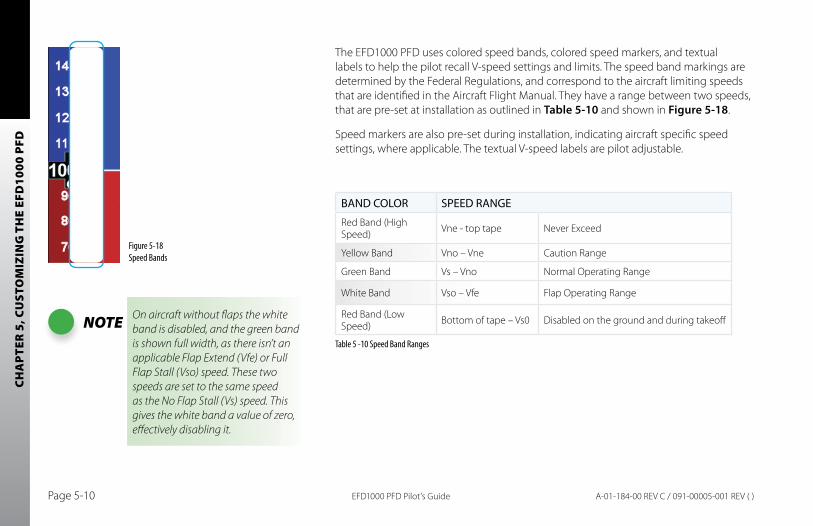
CHA
PTER
5, C
UST
OM
IZIN
G T
HE
EFD
1000
PFD
EFD1000 PFD Pilot’s GuidePage 5-10 A-01-184-00 REV C / 091-00005-001 REV ( )
The EFD1000 PFD uses colored speed bands, colored speed markers, and textual labels to help the pilot recall V-speed settings and limits. The speed band markings are determined by the Federal Regulations, and correspond to the aircraft limiting speeds that are identified in the Aircraft Flight Manual. They have a range between two speeds, that are pre-set at installation as outlined in Table 5-10 and shown in Figure 5-18.
Speed markers are also pre-set during installation, indicating aircraft specific speed settings, where applicable. The textual V-speed labels are pilot adjustable.
BAND COLOR SPEED RANGE
Red Band (High Speed) Vne - top tape Never Exceed
Yellow Band Vno – Vne Caution Range
Green Band Vs – Vno Normal Operating Range
White Band Vso – Vfe Flap Operating Range
Red Band (Low Speed) Bottom of tape – Vs0 Disabled on the ground and during takeoff
Table 5 -10 Speed Band Ranges
Figure 5-18 Speed Bands
NOTE On aircraft without flaps the white band is disabled, and the green band is shown full width, as there isn’t an applicable Flap Extend (Vfe) or Full Flap Stall (Vso) speed. These two speeds are set to the same speed as the No Flap Stall (Vs) speed. This gives the white band a value of zero, effectively disabling it.
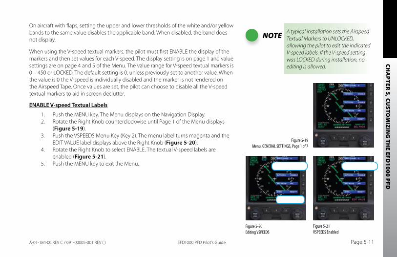
CHA
PTER 5, CU
STOM
IZING
THE EFD
1000 PFD
EFD1000 PFD Pilot’s Guide Page 5-11A-01-184-00 REV C / 091-00005-001 REV ( )
On aircraft with flaps, setting the upper and lower thresholds of the white and/or yellow bands to the same value disables the applicable band. When disabled, the band does not display.
When using the V-speed textual markers, the pilot must first ENABLE the display of the markers and then set values for each V-speed. The display setting is on page 1 and value settings are on page 4 and 5 of the Menu. The value range for V-speed textual markers is 0 – 450 or LOCKED. The default setting is 0, unless previously set to another value. When the value is 0 the V-speed is individually disabled and the marker is not rendered on the Airspeed Tape. Once values are set, the pilot can choose to disable all the V-speed textual markers to aid in screen declutter.
ENAbLE V-speed Textual Labels
1. Push the MENU key. The Menu displays on the Navigation Display.2. Rotate the Right Knob counterclockwise until Page 1 of the Menu displays
(Figure 5-19).3. Push the VSPEEDS Menu Key (Key 2). The menu label turns magenta and the
EDIT VALUE label displays above the Right Knob (Figure 5-20).4. Rotate the Right Knob to select ENABLE. The textual V-speed labels are
enabled (Figure 5-21).5. Push the MENU key to exit the Menu.
Figure 5-21 VSPEEDS Enabled
Figure 5-20 Editing VSPEEDS
Figure 5-19 Menu, GENERAL SETTINGS, Page 1 of 7
NOTE A typical installation sets the Airspeed Textual Markers to UNLOCKED, allowing the pilot to edit the indicated V-speed labels. If the V-speed setting was LOCKED during installation, no editing is allowed.
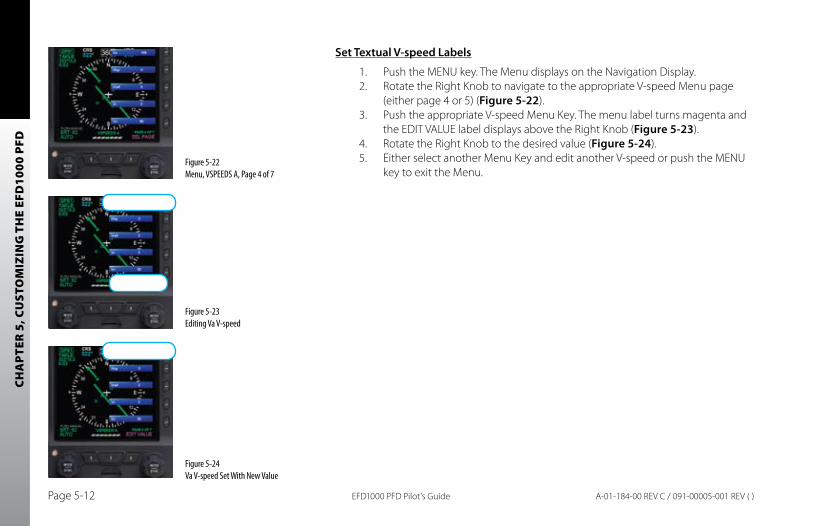
CHA
PTER
5, C
UST
OM
IZIN
G T
HE
EFD
1000
PFD
EFD1000 PFD Pilot’s GuidePage 5-12 A-01-184-00 REV C / 091-00005-001 REV ( )
Set Textual V-speed Labels
1. Push the MENU key. The Menu displays on the Navigation Display.2. Rotate the Right Knob to navigate to the appropriate V-speed Menu page
(either page 4 or 5) (Figure 5-22).3. Push the appropriate V-speed Menu Key. The menu label turns magenta and
the EDIT VALUE label displays above the Right Knob (Figure 5-23).4. Rotate the Right Knob to the desired value (Figure 5-24).5. Either select another Menu Key and edit another V-speed or push the MENU
key to exit the Menu.Figure 5-22 Menu, VSPEEDS A, Page 4 of 7
Figure 5-23 Editing Va V-speed
Figure 5-24 Va V-speed Set With New Value
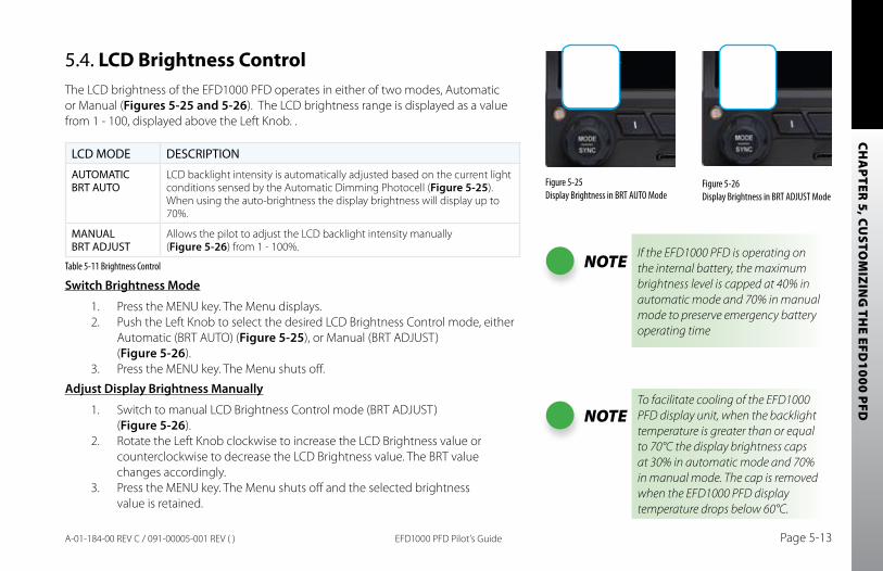
CHA
PTER 5, CU
STOM
IZING
THE EFD
1000 PFD
EFD1000 PFD Pilot’s Guide Page 5-13A-01-184-00 REV C / 091-00005-001 REV ( )
5.4. LCD Brightness ControlThe LCD brightness of the EFD1000 PFD operates in either of two modes, Automatic or Manual (Figures 5-25 and 5-26). The LCD brightness range is displayed as a value from 1 - 100, displayed above the Left Knob. .
LCD MODE DESCRIPTION
AUTOMATIC BRT AUTO
LCD backlight intensity is automatically adjusted based on the current light conditions sensed by the Automatic Dimming Photocell (Figure 5-25). When using the auto-brightness the display brightness will display up to 70%.
MANUAL BRT ADJUST
Allows the pilot to adjust the LCD backlight intensity manually (Figure 5-26) from 1 - 100%.
Table 5-11 Brightness Control
Switch brightness Mode
1. Press the MENU key. The Menu displays.2. Push the Left Knob to select the desired LCD Brightness Control mode, either
Automatic (BRT AUTO) (Figure 5-25), or Manual (BRT ADJUST) (Figure 5-26).
3. Press the MENU key. The Menu shuts off.
Adjust Display brightness Manually
1. Switch to manual LCD Brightness Control mode (BRT ADJUST) (Figure 5-26).
2. Rotate the Left Knob clockwise to increase the LCD Brightness value or counterclockwise to decrease the LCD Brightness value. The BRT value changes accordingly.
3. Press the MENU key. The Menu shuts off and the selected brightness value is retained.
Figure 5-26 Display Brightness in BRT ADJUST Mode
Figure 5-25 Display Brightness in BRT AUTO Mode
NOTE If the EFD1000 PFD is operating on the internal battery, the maximum brightness level is capped at 40% in automatic mode and 70% in manual mode to preserve emergency battery operating time
NOTETo facilitate cooling of the EFD1000 PFD display unit, when the backlight temperature is greater than or equal to 70°C the display brightness caps at 30% in automatic mode and 70% in manual mode. The cap is removed when the EFD1000 PFD display temperature drops below 60°C.

CHA
PTER
5, C
UST
OM
IZIN
G T
HE
EFD
1000
PFD
EFD1000 PFD Pilot’s GuidePage 5-14 A-01-184-00 REV C / 091-00005-001 REV ( )
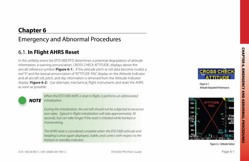
CHA
PTER 6, EMERG
ENCY
AN
D A
BN
ORM
AL PRO
CEDU
RES
EFD1000 PFD Pilot’s Guide Page 6-1A-01-184-00 REV C / 091-00005-001 REV ( )
Chapter 6Emergency and Abnormal Procedures
6.1. In Flight AHRS ResetIn the unlikely event the EFD1000 PFD determines a potential degradation of attitude information, a warning annunciation, CROSS CHECK ATTITUDE, displays above the aircraft reference symbol (Figure 6-1). If the attitude pitch or roll data become invalid, a red “X” and the textual annunciation of “ATTITUDE FAIL” display on the Attitude Indicator and all aircraft roll, pitch, and slip information is removed from the Attitude Indicator display (Figure 6-2). Use alternate, mechanical, flight instruments and reset the AHRS as soon as possible.
NOTEWhen the EFD1000 AHRS is reset in flight, it performs an abbreviated initialization.
During the initialization, the aircraft should not be subjected to excessive turn rates. Typical in-flight initialization will take approximately 30 seconds, but can take longer if the reset is initiated while banked or maneuvering.
The AHRS reset is considered complete when the EFD1000 attitude and heading is once again displayed, stable, and correct with respect to the horizon or standby indicator.
Figure 6-1 Attitude Degraded Performance
Figure 6-2 Attitude Failure
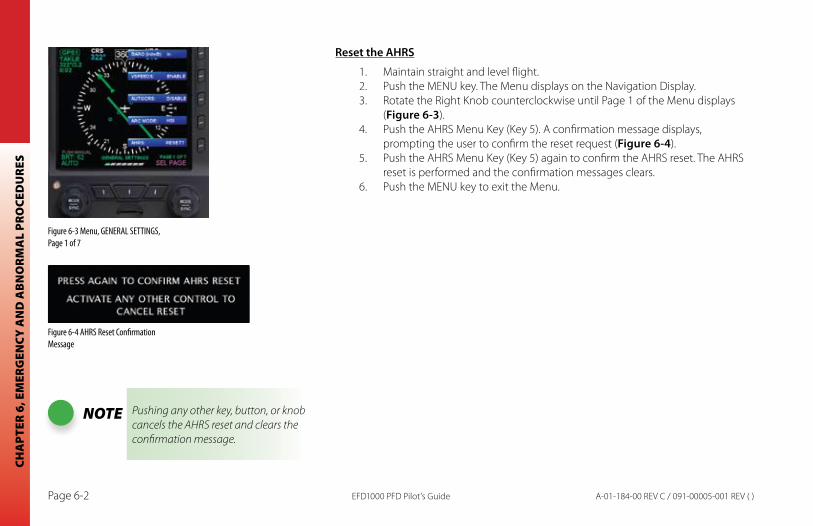
CHA
PTER
6, E
MER
GEN
CY A
ND
AB
NO
RMA
L PR
OCE
DU
RES
EFD1000 PFD Pilot’s GuidePage 6-2 A-01-184-00 REV C / 091-00005-001 REV ( )
Reset the AHRS
1. Maintain straight and level flight.2. Push the MENU key. The Menu displays on the Navigation Display.3. Rotate the Right Knob counterclockwise until Page 1 of the Menu displays
(Figure 6-3).4. Push the AHRS Menu Key (Key 5). A confirmation message displays,
prompting the user to confirm the reset request (Figure 6-4).5. Push the AHRS Menu Key (Key 5) again to confirm the AHRS reset. The AHRS
reset is performed and the confirmation messages clears.6. Push the MENU key to exit the Menu.
NOTE Pushing any other key, button, or knob cancels the AHRS reset and clears the confirmation message.
Figure 6-3 Menu, GENERAL SETTINGS, Page 1 of 7
Figure 6-4 AHRS Reset Confirmation Message
CHA
PTER 6, EMERG
ENCY
AN
D A
BN
ORM
AL PRO
CEDU
RES
EFD1000 PFD Pilot’s Guide Page 6-3A-01-184-00 REV C / 091-00005-001 REV ( )
6.2. Pitot/Static System BlockageA static line blockage will result in altitude remaining fixed and a zero vertical speed despite aircraft pitch and/or power setting changes. In addition, IAS indications will be incorrect if the static line is blocked. Errors will typically be noticed in the climb or descent phase of flight. When descending, ambient pressure increases, which will result in the indicated airspeed reading less than the actual airspeed. The opposite effect will be observed in a climb.
A pitot line blockage will result in the airspeed indicator behaving like an altimeter when the aircraft altitude changes, and it does not respond to airspeed changes.
When Pitot or Static Line is blocked
1. Select an alternate static source.2. Set Pitot Heat to ON.
CAUTIONMost light aircraft have only a single pitot and static port available for flight instrument use. As such, the pitot and static lines used by the EFD1000 system are shared with those lines used by the standby airspeed indicator and altimeter. Should these lines become blocked, such as might occur due to inadvertent icing encounter, both the standby indicators and the EFD1000 indicators will display erroneous airspeed and/or altitude information.
In the event of erroneous airspeed and altitude information at the EFD1000, the EFD1000 Attitude Monitor will present a “CROSS CHECK ATTITUDE” annunciation.
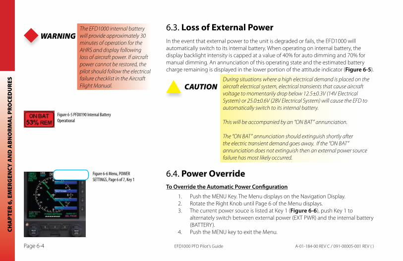
CHA
PTER
6, E
MER
GEN
CY A
ND
AB
NO
RMA
L PR
OCE
DU
RES
EFD1000 PFD Pilot’s GuidePage 6-4 A-01-184-00 REV C / 091-00005-001 REV ( )
6.3. Loss of External PowerIn the event that external power to the unit is degraded or fails, the EFD1000 will automatically switch to its internal battery. When operating on internal battery, the display backlight intensity is capped at a value of 40% for auto dimming and 70% for manual dimming. An annunciation of this operating state and the estimated battery charge remaining is displayed in the lower portion of the attitude indicator (Figure 6-5).
CAUTIONDuring situations where a high electrical demand is placed on the aircraft electrical system, electrical transients that cause aircraft voltage to momentarily drop below 12.5±0.3V (14V Electrical System) or 25.0±0.6V (28V Electrical System) will cause the EFD to automatically switch to its internal battery.
This will be accompanied by an “ON BAT” annunciation.
The “ON BAT” annunciation should extinguish shortly after the electric transient demand goes away. If the “ON BAT” annunciation does not extinguish then an external power source failure has most likely occurred.
6.4. Power OverrideTo Override the Automatic Power Configuration
1. Push the MENU Key. The Menu displays on the Navigation Display.2. Rotate the Right Knob until Page 6 of the Menu displays.3. The current power souce is listed at Key 1 (Figure 6-6), push Key 1 to
alternately switch between external power (EXT PWR) and the internal battery (BATTERY).
4. Push the MENU key to exit the Menu.
Figure 6-5 PFD0190 Internal Battery Operational
Figure 6-6 Menu, POWER SETTINGS, Page 6 of 7, Key 1
WARNINGThe EFD1000 internal battery will provide approximately 30 minutes of operation for the AHRS and display following loss of aircraft power. If aircraft power cannot be restored, the pilot should follow the electrical failure checklist in the Aircraft Flight Manual.
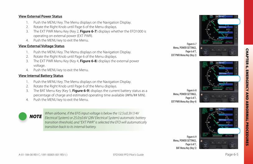
CHA
PTER 6, EMERG
ENCY
AN
D A
BN
ORM
AL PRO
CEDU
RES
EFD1000 PFD Pilot’s Guide Page 6-5A-01-184-00 REV C / 091-00005-001 REV ( )
View External Power Status
1. Push the MENU Key. The Menu displays on the Navigation Display.2. Rotate the Right Knob until Page 6 of the Menu displays.3. The EXT PWR Menu Key (Key 2, Figure 6-7) displays whether the EFD1000 is
operating on external power (EXT PWR). 4. Push the MENU key to exit the Menu.
View External Voltage Status
1. Push the MENU Key. The Menu displays on the Navigation Display.2. Rotate the Right Knob until Page 6 of the Menu displays.3. The EXT PWR Menu Key (Key 4, Figure 6-8) displays the external power
voltage.4. Push the MENU key to exit the Menu.
View Internal battery Status
1. Push the MENU Key. The Menu displays on the Navigation Display.2. Rotate the Right Knob until Page 6 of the Menu displays.3. The BAT Menu Key (Key 5, Figure 6-9) displays the current battery status as a
percentage of charge and estimated operating time available (##%/## MIN).4. Push the MENU key to exit the Menu.
NOTEWhen airborne, if the EFIS input voltage is below the 12.5±0.3V (14V Electrical System) or 25.0±0.6V (28V Electrical System) automatic battery transition threshold, and “EXT PWR” is selected the EFD will automatically transition back to its internal battery.
Figure 6-7 Menu, POWER SETTINGS,
Page 6 of 7, EXT PWR Menu Key (Key 2)
Figure 6-8 Menu, POWER SETTINGS,
Page 6 of 7, EXT PWR Menu Key (Key 4)
Figure 6-9 Menu, POWER SETTINGS,
Page 6 of 7, BAT Menu Key (Key 5)
CHA
PTER
6, E
MER
GEN
CY A
ND
AB
NO
RMA
L PR
OCE
DU
RES
EFD1000 PFD Pilot’s GuidePage 6-6 A-01-184-00 REV C / 091-00005-001 REV ( )
6.5. Abnormal Shutdown ProcedureThe EFD1000 PFD is typically powered through an EFIS Power Control switch that is connected to the aircraft battery bus. The system will power up, based on the position of the EFIS Power Control switch or switch that controls power to the Battery bus. Typically, when on the ground, powering up/down the aircraft simultaneously powers on/off the EFD1000 PFD. If the EFD1000 PFD has been powered off and aircraft power is available to the EFD1000 PFD, pressing the REV button momentarily will turn on the EFD1000 PFD.
Power Off Manually
1. Pull the circuit breaker.2. Press and hold the REV key until the EFD1000 PFD powers off.
Or
1. Press the MENU key. The Menu displays.2. Rotate the Right Knob to display Page 6 of 7, POWER SETTINGS.3. Press Menu Key 3, SHUT DOWN. The power down sequence initiates.
Power On Manually
Press the REV key until the EFD1000 PFD powers on.•
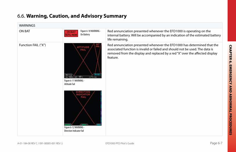
CHA
PTER 6, EMERG
ENCY
AN
D A
BN
ORM
AL PRO
CEDU
RES
EFD1000 PFD Pilot’s Guide Page 6-7A-01-184-00 REV C / 091-00005-001 REV ( )
6.6. Warning, Caution, and Advisory Summary
WARNINGS
ON BAT Red annunciation presented whenever the EFD1000 is operating on the internal battery. Will be accompanied by an indication of the estimated battery life remaining.
Function FAIL (“X”) Red annunciation presented whenever the EFD1000 has determined that the associated function is invalid or failed and should not be used. The data is removed from the display and replaced by a red “X” over the affected display feature.
Figure 6-10 WARNING - On Battery
Figure 6-11 WARNING - Attitude Fail
Figure 6-12 WARNING - Direction Indicator Fail
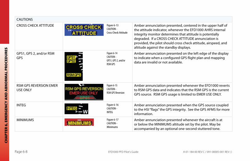
CHA
PTER
6, E
MER
GEN
CY A
ND
AB
NO
RMA
L PR
OCE
DU
RES
EFD1000 PFD Pilot’s GuidePage 6-8 A-01-184-00 REV C / 091-00005-001 REV ( )
CAUTIONS
CROSS CHECK ATTITUDE Amber annunciation presented, centered in the upper half of the attitude indicator, whenever the EFD1000 AHRS internal integrity monitor determines that attitude is potentially degraded. If a CROSS CHECK ATTITUDE annunciation is provided, the pilot should cross check attitude, airspeed, and altitude against the standby displays.
GPS1, GPS 2, and/or RSM GPS
Amber annunciation presented on the left edge of the display to indicate when a configured GPS flight plan and mapping data are invalid or not available.
RSM GPS REVERSION EMER USE ONLY
Amber annunciation presented whenever the EFD1000 reverts to RSM GPS data and indicates that the RSM GPS is the current GPS source. RSM GPS usage is limited to EMER USE ONLY.
INTEG Amber annunciation presented when the GPS source coupled to the HSI “flags” the GPS integrity. See the GPS AFMS for more information.
MINIMUMS Amber annunciation presented whenever the aircraft is at or below the MINIMUMS altitude set by the pilot. May be accompanied by an optional one-second stuttered tone.
Figure 6-13 CAUTION - Cross Check Attitude
Figure 6-14 CAUTION - GPS1, GPS 2, and/or RSM GPS
Figure 6-15 CAUTION - RSM GPS Reversion
Figure 6-16 CAUTION - INTEG
Figure 6-17 CAUTION - Minimums
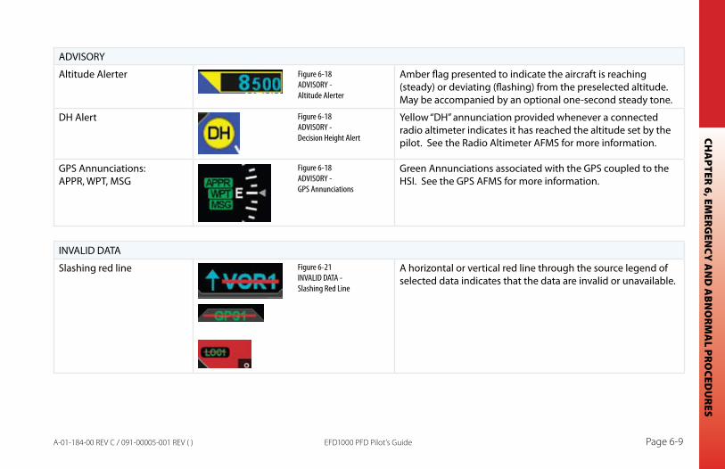
CHA
PTER 6, EMERG
ENCY
AN
D A
BN
ORM
AL PRO
CEDU
RES
EFD1000 PFD Pilot’s Guide Page 6-9A-01-184-00 REV C / 091-00005-001 REV ( )
ADVISORY
Altitude Alerter Amber flag presented to indicate the aircraft is reaching (steady) or deviating (flashing) from the preselected altitude. May be accompanied by an optional one-second steady tone.
DH Alert Yellow “DH” annunciation provided whenever a connected radio altimeter indicates it has reached the altitude set by the pilot. See the Radio Altimeter AFMS for more information.
GPS Annunciations: APPR, WPT, MSG
Green Annunciations associated with the GPS coupled to the HSI. See the GPS AFMS for more information.
INVALID DATA
Slashing red line A horizontal or vertical red line through the source legend of selected data indicates that the data are invalid or unavailable.
Figure 6-18 ADVISORY - Altitude Alerter
Figure 6-21 INVALID DATA - Slashing Red Line
Figure 6-18 ADVISORY - Decision Height Alert
Figure 6-18 ADVISORY - GPS Annunciations

CHA
PTER
6, E
MER
GEN
CY A
ND
AB
NO
RMA
L PR
OCE
DU
RES
EFD1000 PFD Pilot’s GuidePage 6-10 A-01-184-00 REV C / 091-00005-001 REV ( )
CHA
PTER 7, A
PPEND
ICES
EFD1000 PFD Pilot’s Guide Page 7-1A-01-184-00 REV C / 091-00005-001 REV ( )
Chapter 7Appendices
7.1. Operating LimitationsThe Aspen EFD1000 PFD Airplane Flight Manual Supplement, A-01-175-00 Revision B (or later FAA Approved revision), contains the limitations that apply to your specific aircraft installations, and must be immediately available to the flight crew when the EFD1000 PFD is being used to provide flight or navigation information. The following are summary, advisory information that apply to most EFD1000 PFD installations.
7.1.1. Weight & Center of Gravity
Installation of the EFD1000 system may result in a small net change to the aircraft empty weight and associated moment arm. Refer to the revised weight and balance records carried in the aircraft for details.
7.1.2. RSM GPS Usage
The EFD1000 RSM GPS is authorized for emergency use only. Position data from the RSM GPS will ONLY be presented following the loss or failure of a certified external GPS navigator.
7.1.3. Geographic Limitation
Like all compass systems, the magnetometer used in the EFD1000 system will experience degraded performance in the vicinity of the magnetic poles. When the
NOTEWhen the RSM GPS is in use, magnetic variation data used by the map is not updated. This can result in misaligned map symbology whenever the external GPS position source is lost and the aircraft travels far enough to produce a significant change in the local magnetic variation.
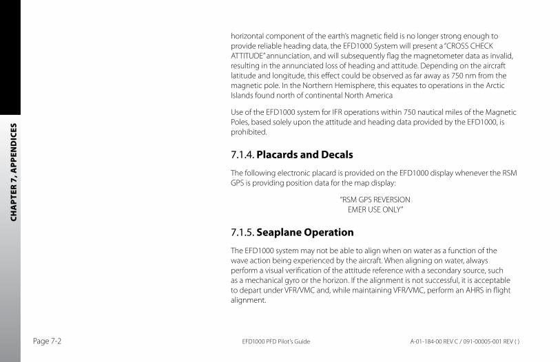
CHA
PTER
7, A
PPEN
DIC
ES
EFD1000 PFD Pilot’s GuidePage 7-2 A-01-184-00 REV C / 091-00005-001 REV ( )
horizontal component of the earth’s magnetic field is no longer strong enough to provide reliable heading data, the EFD1000 System will present a “CROSS CHECK ATTITUDE” annunciation, and will subsequently flag the magnetometer data as invalid, resulting in the annunciated loss of heading and attitude. Depending on the aircraft latitude and longitude, this effect could be observed as far away as 750 nm from the magnetic pole. In the Northern Hemisphere, this equates to operations in the Arctic Islands found north of continental North America
Use of the EFD1000 system for IFR operations within 750 nautical miles of the Magnetic Poles, based solely upon the attitude and heading data provided by the EFD1000, is prohibited.
7.1.4. Placards and Decals
The following electronic placard is provided on the EFD1000 display whenever the RSM GPS is providing position data for the map display:
“RSM GPS REVERSION EMER USE ONLY”
7.1.5. Seaplane Operation
The EFD1000 system may not be able to align when on water as a function of the wave action being experienced by the aircraft. When aligning on water, always perform a visual verification of the attitude reference with a secondary source, such as a mechanical gyro or the horizon. If the alignment is not successful, it is acceptable to depart under VFR/VMC and, while maintaining VFR/VMC, perform an AHRS in flight alignment.
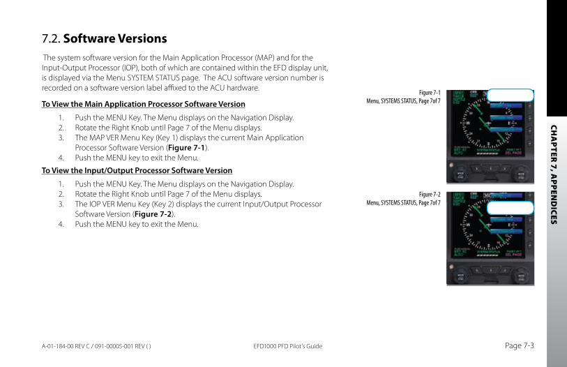
CHA
PTER 7, A
PPEND
ICES
EFD1000 PFD Pilot’s Guide Page 7-3A-01-184-00 REV C / 091-00005-001 REV ( )
7.2. Software Versions The system software version for the Main Application Processor (MAP) and for the Input-Output Processor (IOP), both of which are contained within the EFD display unit, is displayed via the Menu SYSTEM STATUS page. The ACU software version number is recorded on a software version label affixed to the ACU hardware.
To View the Main Application Processor Software Version
1. Push the MENU Key. The Menu displays on the Navigation Display.2. Rotate the Right Knob until Page 7 of the Menu displays.3. The MAP VER Menu Key (Key 1) displays the current Main Application
Processor Software Version (Figure 7-1).4. Push the MENU key to exit the Menu.
To View the Input/Output Processor Software Version
1. Push the MENU Key. The Menu displays on the Navigation Display.2. Rotate the Right Knob until Page 7 of the Menu displays.3. The IOP VER Menu Key (Key 2) displays the current Input/Output Processor
Software Version (Figure 7-2).4. Push the MENU key to exit the Menu.
Figure 7-1 Menu, SYSTEMS STATUS, Page 7of 7
Figure 7-2 Menu, SYSTEMS STATUS, Page 7of 7
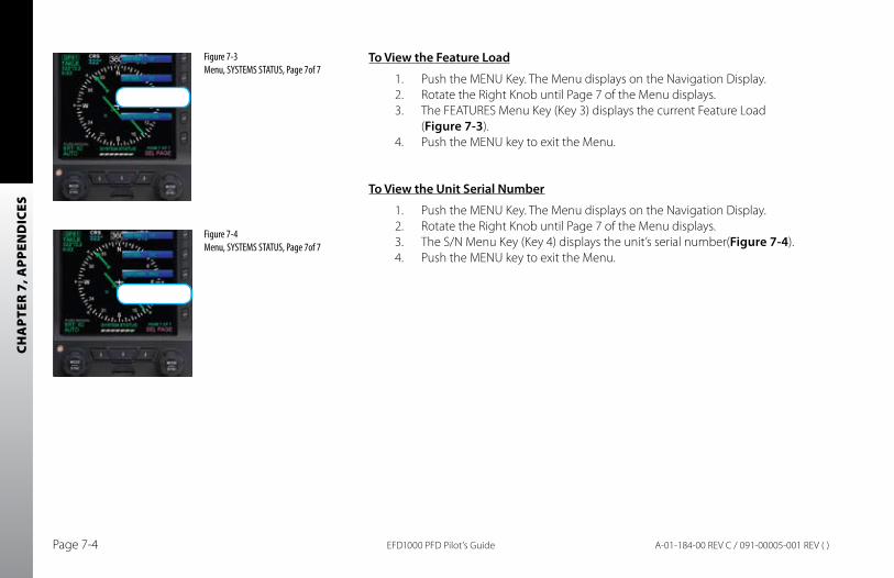
CHA
PTER
7, A
PPEN
DIC
ES
EFD1000 PFD Pilot’s GuidePage 7-4 A-01-184-00 REV C / 091-00005-001 REV ( )
To View the Feature Load
1. Push the MENU Key. The Menu displays on the Navigation Display.2. Rotate the Right Knob until Page 7 of the Menu displays.3. The FEATURES Menu Key (Key 3) displays the current Feature Load
(Figure 7-3).4. Push the MENU key to exit the Menu.
To View the Unit Serial Number
1. Push the MENU Key. The Menu displays on the Navigation Display.2. Rotate the Right Knob until Page 7 of the Menu displays.3. The S/N Menu Key (Key 4) displays the unit’s serial number(Figure 7-4).4. Push the MENU key to exit the Menu.
Figure 7-3 Menu, SYSTEMS STATUS, Page 7of 7
Figure 7-4 Menu, SYSTEMS STATUS, Page 7of 7
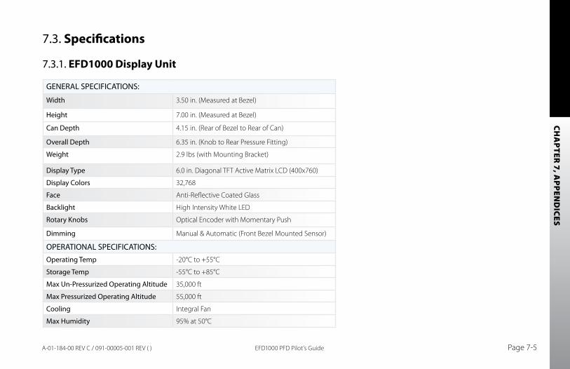
CHA
PTER 7, A
PPEND
ICES
EFD1000 PFD Pilot’s Guide Page 7-5A-01-184-00 REV C / 091-00005-001 REV ( )
7.3. Specifications
7.3.1. EFD1000 Display Unit
GENERAL SPECIFICATIONS:
Width 3.50 in. (Measured at Bezel)
Height 7.00 in. (Measured at Bezel)
Can Depth 4.15 in. (Rear of Bezel to Rear of Can)
Overall Depth 6.35 in. (Knob to Rear Pressure Fitting)
Weight 2.9 lbs (with Mounting Bracket)
Display Type 6.0 in. Diagonal TFT Active Matrix LCD (400x760)
Display Colors 32,768
Face Anti-Reflective Coated Glass
Backlight High Intensity White LED
Rotary Knobs Optical Encoder with Momentary Push
Dimming Manual & Automatic (Front Bezel Mounted Sensor)
OPERATIONAL SPECIFICATIONS:Operating Temp -20°C to +55°C
Storage Temp -55°C to +85°C
Max Un-Pressurized Operating Altitude 35,000 ft
Max Pressurized Operating Altitude 55,000 ft
Cooling Integral Fan
Max Humidity 95% at 50°C
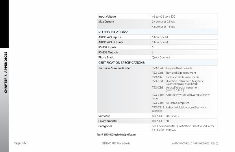
CHA
PTER
7, A
PPEN
DIC
ES
EFD1000 PFD Pilot’s GuidePage 7-6 A-01-184-00 REV C / 091-00005-001 REV ( )
Input Voltage +8 to +32 Volts DC
Max Current 2.4 Amps @ 28 Vdc
4.8 Amps @ 14 Vdc
I/O SPECIFICATIONS:ARINC 429 Inputs 5 Low Speed
ARINC 429 Outputs 1 Low Speed
RS-232 Inputs 5
RS-232 Outputs 3
Pitot / Static Quick Connect
CERTIFICATION SPECIFICATIONS:
Technical Standard Order TSO-C2d Airspeed Instruments
TSO-C3d Turn and Slip Instrument
TSO-C4c Bank and Pitch InstrumentsTSO-C6d Direction Instrument Magnetic (Gyroscopically Stabilized)TSO-C8d Vertical Velocity Instrument (Rate of Climb)
TSO-C10b Altitude Pressure Activated Sensitive Type
TSO-C106 Air Data Computer
TSO-C113 Airborne Multipurpose Electronic Displays
Software RTCA DO-178B Level C
Environmental RTCA DO-160E
Categories See Environmental Qualification Sheet found in the installation manual.
Table 7-2 EFD1000 Display Unit Specifications
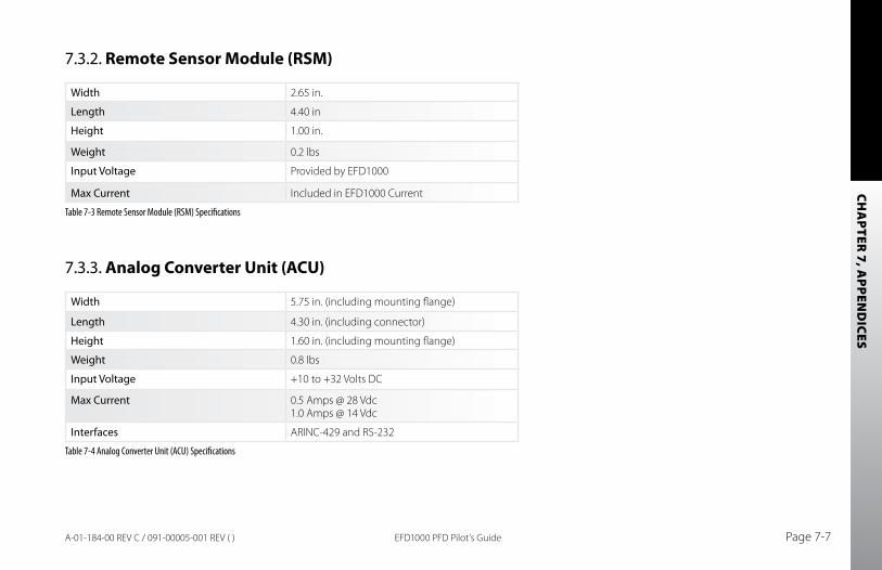
CHA
PTER 7, A
PPEND
ICES
EFD1000 PFD Pilot’s Guide Page 7-7A-01-184-00 REV C / 091-00005-001 REV ( )
7.3.2. Remote Sensor Module (RSM)
Width 2.65 in.
Length 4.40 in
Height 1.00 in.
Weight 0.2 lbs
Input Voltage Provided by EFD1000
Max Current Included in EFD1000 Current
Table 7-3 Remote Sensor Module (RSM) Specifications
7.3.3. Analog Converter Unit (ACU)
Width 5.75 in. (including mounting flange)
Length 4.30 in. (including connector)
Height 1.60 in. (including mounting flange)
Weight 0.8 lbs
Input Voltage +10 to +32 Volts DC
Max Current 0.5 Amps @ 28 Vdc 1.0 Amps @ 14 Vdc
Interfaces ARINC-429 and RS-232
Table 7-4 Analog Converter Unit (ACU) Specifications
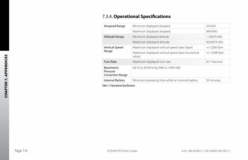
CHA
PTER
7, A
PPEN
DIC
ES
EFD1000 PFD Pilot’s GuidePage 7-8 A-01-184-00 REV C / 091-00005-001 REV ( )
7.3.4. Operational Specifications
Airspeed Range Minimum displayed airspeed 20 KIAS
Maximum displayed airspeed 999 KIAS
Altitude Range Minimum displayed altitude -1,500 ft MSL
Maximum displayed altitude 60,000 ft MSL
Vertical Speed Range
Maximum displayed vertical speed rates (tape) +/-2,000 fpm
Maximum displayed vertical speed rates (numerical value)
+/- 9,990 fpm
Turn Rate Maximum displayed turn rate 4.5 °/second
Barometric Pressure Correction Range
28.10 to 30.99 InHg (946 to 1049 mB)
Internal Battery Minimum operating time while on internal battery 30 minutes
Table 7-5 Operational Specifications
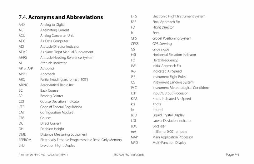
EFD1000 PFD Pilot’s Guide Page 7-9A-01-184-00 REV C / 091-00005-001 REV ( )
7.4. Acronyms and AbbreviationsA/D Analog to DigitalAC Alternating CurrentACU Analog Converter UnitADC Air Data ComputerADI Attitude Director IndicatorAFMS Airplane Flight Manual SupplementAHRS Attitude Heading Reference SystemAI Attitude IndicatorAP or A/P AutopilotAPPR Approach ARC Partial heading arc format (100°)ARINC Aeronautical Radio Inc.BC Back CourseBP Bearing PointerCDI Course Deviation IndicatorCFR Code of Federal RegulationsCM Configuration ModuleCRS CourseDC Direct CurrentDH Decision HeightDME Distance Measuring EquipmentEEPROM Electrically Erasable Programmable Read-Only MemoryEFD Evolution Flight Display
EFIS Electronic Flight Instrument SystemFAF Final Approach FixFD Flight Directorft FeetGPS Global Positioning SystemGPSS GPS SteeringGS Glide slopeHSI Horizontal Situation IndicatorHz Hertz (frequency)IAF Initial Approach FixIAS Indicated Air SpeedIFR Instrument Fight RulesILS Instrument Landing SystemIMC Instrument Meteorological ConditionsIOP Input/Output ProcessorKIAS Knots Indicated Air Speedkts Knotslb poundLCD Liquid Crystal DisplayLDI Lateral Deviation IndicatorLOC LocalizermA milliamp, 0.001 ampereMAP Main Application ProcessorMFD Multi-Function Display
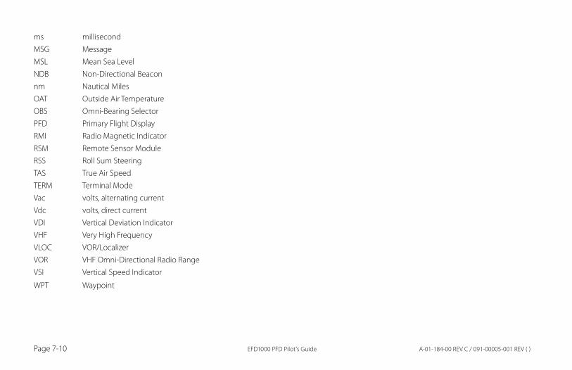
EFD1000 PFD Pilot’s GuidePage 7-10 A-01-184-00 REV C / 091-00005-001 REV ( )
ms millisecondMSG MessageMSL Mean Sea LevelNDB Non-Directional Beaconnm Nautical MilesOAT Outside Air TemperatureOBS Omni-Bearing SelectorPFD Primary Flight DisplayRMI Radio Magnetic IndicatorRSM Remote Sensor ModuleRSS Roll Sum SteeringTAS True Air SpeedTERM Terminal Mode Vac volts, alternating currentVdc volts, direct currentVDI Vertical Deviation IndicatorVHF Very High FrequencyVLOC VOR/LocalizerVOR VHF Omni-Directional Radio RangeVSI Vertical Speed Indicator
WPT Waypoint
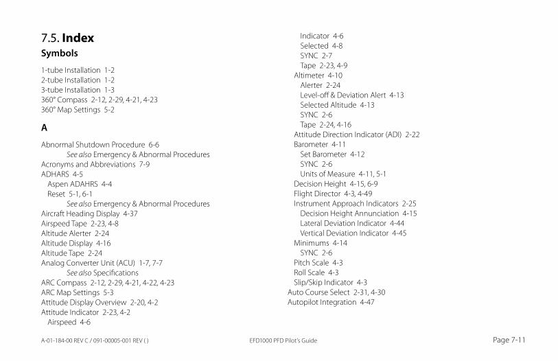
EFD1000 PFD Pilot’s Guide Page 7-11A-01-184-00 REV C / 091-00005-001 REV ( )
7.5. IndexSymbols
1-tube Installation 1-22-tube Installation 1-23-tube Installation 1-3360° Compass 2-12, 2-29, 4-21, 4-23360° Map Settings 5-2
A
Abnormal Shutdown Procedure 6-6 See also Emergency & Abnormal Procedures
Acronyms and Abbreviations 7-9ADHARS 4-5
Aspen ADAHRS 4-4Reset 5-1, 6-1
See also Emergency & Abnormal ProceduresAircraft Heading Display 4-37Airspeed Tape 2-23, 4-8Altitude Alerter 2-24Altitude Display 4-16Altitude Tape 2-24Analog Converter Unit (ACU) 1-7, 7-7
See also SpecificationsARC Compass 2-12, 2-29, 4-21, 4-22, 4-23ARC Map Settings 5-3Attitude Display Overview 2-20, 4-2Attitude Indicator 2-23, 4-2
Airspeed 4-6
Indicator 4-6Selected 4-8SYNC 2-7Tape 2-23, 4-9
Altimeter 4-10Alerter 2-24Level-off & Deviation Alert 4-13Selected Altitude 4-13SYNC 2-6Tape 2-24, 4-16
Attitude Direction Indicator (ADI) 2-22Barometer 4-11
Set Barometer 4-12SYNC 2-6Units of Measure 4-11, 5-1
Decision Height 4-15, 6-9Flight Director 4-3, 4-49Instrument Approach Indicators 2-25
Decision Height Annunciation 4-15Lateral Deviation Indicator 4-44Vertical Deviation Indicator 4-45
Minimums 4-14SYNC 2-6
Pitch Scale 4-3Roll Scale 4-3Slip/Skip Indicator 4-3
Auto Course Select 2-31, 4-30Autopilot Integration 4-47

EFD1000 PFD Pilot’s GuidePage 7-12 A-01-184-00 REV C / 091-00005-001 REV ( )
b
Barometer 4-11Units of Measuer 5-1
Barometric Pressure Display 4-19Battery Backup 6-4
Override Automatic Power 6-4View Internal Battery Status 6-5
Bearing Pointers 2-33, 4-33Bearing Pointer Source Selection 4-33Brightness 5-13
Change Display Brightness 2-16, 5-13Buttons
See Controls
C
Cautions (explained) xviiiCDI Navigation Source Selection 4-27, 4-32Cleaning the Display Screen 2-17Color Philosophy xviiCompass 4-21Configuration Module 1-6
See also SpecificationsControls 2-1, 2-4
Buttons 2-8Lower Left 2-10Lower Middle 2-9Lower Right 2-10MENU 2-13
Range 2-17Reversion (REV) 2-17
Control & Display Overview 2-2Hot Keys/Menu Keys 2-11
See also Specifications360/ARC 4-23GPSS 4-49MAP 4-40MIN 4-14TPS 4-9, 4-16
Knobs 2-4Left 2-5, 2-7Right 2-5, 2-6SYNC Function 2-6
Quick Overview 3-3Conventions xv
Color Philosophy xviiExample Graphics xixPilot Familiarity xixTerminology xvWarnings, Cautions, Notes xviii
Copyrights & Trademarks xiCourse
Pointer 2-30, 4-24SYNC 2-7
Course Deviation Indicator (CDI) 4-26Customizing the EFD1000 PFD 5-1
Customizing the Map 5-6
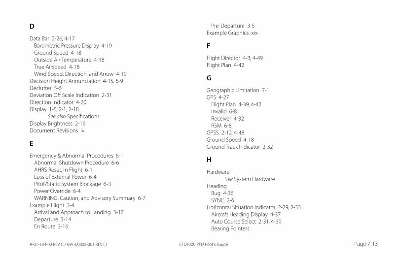
EFD1000 PFD Pilot’s Guide Page 7-13A-01-184-00 REV C / 091-00005-001 REV ( )
D
Data Bar 2-26, 4-17Barometric Pressure Display 4-19Ground Speed 4-18Outside Air Temperature 4-18True Airspeed 4-18Wind Speed, Direction, and Arrow 4-19
Decision Height Annunciation 4-15, 6-9Declutter 5-6Deviation Off Scale Indication 2-31Direction Indicator 4-20Display 1-5, 2-1, 2-18
See also SpecificationsDisplay Brightness 2-16Document Revisions iv
E
Emergency & Abnormal Procedures 6-1Abnormal Shutdown Procedure 6-6AHRS Reset, In Flight 6-1Loss of External Power 6-4Pitot/Static System Blockage 6-3Power Override 6-4WARNING, Caution, and Advisory Summary 6-7
Example Flight 3-4Arrival and Approach to Landing 3-17Departure 3-14En Route 3-16
Pre-Departure 3-5Example Graphics xix
F
Flight Director 4-3, 4-49Flight Plan 4-42
G
Geographic Limitation 7-1GPS 4-27
Flight Plan 4-39, 4-42Invalid 6-8Receiver 4-32RSM 6-8
GPSS 2-12, 4-48Ground Speed 4-18Ground Track Indicator 2-32
H
Hardware See System Hardware
HeadingBug 4-36SYNC 2-6
Horizontal Situation Indicator 2-29, 2-33Aircraft Heading Display 4-37Auto Course Select 2-31, 4-30Bearing Pointers
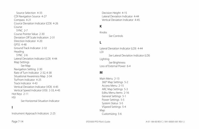
EFD1000 PFD Pilot’s GuidePage 7-14 A-01-184-00 REV C / 091-00005-001 REV ( )
Source Selection 4-33CDI Navigation Source 4-27Compass 4-21Cource Deviation Indicator (CDI) 4-26Course
SYNC 2-7Course Pointer Value 2-30Deviation Off Scale Indication 2-31Direction Indicator 4-20GPSS 4-48Ground Track Indicator 2-32Heading
SYNC 2-6Lateral Deviation Indicator (LDI) 4-44Map Settings
See MapNavigation Setting 2-30Rate of Turn Indicator 2-32, 4-38Situational Awareness Map 2-34To/From Indicator 4-25Track Indicator 4-43Vertical Deviation Indicator (VDI) 4-45Vertical Speed Indicator (VSI) 2-33, 4-45
Hot Keys 2-11HSI
See Horizontal Situation Indicator
I
Instrument Approach Indicators 2-25
Decision Height 4-15Lateral Deviation Indicator 4-44Vertical Deviation Indicator 4-45
K
Knobs See Controls
L
Lateral Deviation Indicator (LDI) 4-44LDI
See Lateral Deviation Indicator (LDI)Lighting
See BrightnessLoss of External Power 6-4
M
Main Menu 2-13360° Map Settings 5-2Access Menu 2-15ARC Map Settings 5-3Editu Menu Items 2-16General Settings 5-1Power Settings 5-5System Status 5-5VSpeed Settings 5-4
MapCustomizing 5-6
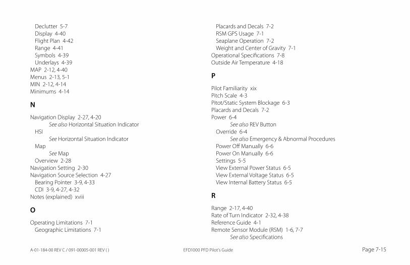
EFD1000 PFD Pilot’s Guide Page 7-15A-01-184-00 REV C / 091-00005-001 REV ( )
Declutter 5-7Display 4-40Flight Plan 4-42Range 4-41Symbols 4-39Underlays 4-39
MAP 2-12, 4-40Menus 2-13, 5-1MIN 2-12, 4-14Minimums 4-14
N
Navigation Display 2-27, 4-20 See also Horizontal Situation Indicator
HSI See Horizontal Situation Indicator
Map See Map
Overview 2-28Navigation Setting 2-30Navigation Source Selection 4-27
Bearing Pointer 3-9, 4-33CDI 3-9, 4-27, 4-32
Notes (explained) xviii
O
Operating Limitations 7-1Geographic Limitations 7-1
Placards and Decals 7-2RSM GPS Usage 7-1Seaplane Operation 7-2Weight and Center of Gravity 7-1
Operational Specifications 7-8Outside Air Temperature 4-18
P
Pilot Familiarity xixPitch Scale 4-3Pitot/Static System Blockage 6-3Placards and Decals 7-2Power 6-4
See also REV ButtonOverride 6-4
See also Emergency & Abnormal ProceduresPower Off Manually 6-6Power On Manually 6-6Settings 5-5View External Power Status 6-5View External Voltage Status 6-5View Internal Battery Status 6-5
R
Range 2-17, 4-40Rate of Turn Indicator 2-32, 4-38Reference Guide 4-1Remote Sensor Module (RSM) 1-6, 7-7
See also Specifications
EFD1000 PFD Pilot’s GuidePage 7-16 A-01-184-00 REV C / 091-00005-001 REV ( )
REV Button 2-17Revisions ivRoll Scale 4-3RSM GPS Usage 7-1
S
Seaplane Operation 7-2Selected Airspeed 4-8Selected Altitude 4-13Selected Heading and Heading Bug 4-36Situational Awareness Map 2-34Slip/Skip Indicator 4-3Software Versions 7-3Specifications 7-5
See also System HardwareAnalog Converter Unit (ACU) 7-7Display Unit 7-5Operational Specifications 7-8Remote Sensor Module (RSM) 7-7
Startup 3-5SYNC 2-6System Hardware 1-5
See also SpecificationsAnalog Converter Unit (ACU) 1-7Configuration Module (CM) 1-6Display Unit 1-5Remote Sensor Module (RSM) 1-6
System Status 5-5
T
Terminology xvTo/From Indicator 2-30, 4-25TPS 2-12, 4-9, 4-16Track Indicator 4-43True Airspeed 4-18
V
VDI See Vertical Deviation Indicator (VDI)
Vertical Deviation Indicator (VDI) 4-45Vertical Speed Indicator (VSI) 2-33, 4-45Voltage 6-4
View External Voltage Status 6-5VSI
See Vertical Speed Indicator (VSI)VSpeeds
Configure 5-8Display 5-4
W
Warning, Caution, and Advisory Summary 6-7Warnings, Cations, and Notes (explained) xviii
See also Emergency & Abnormal ProceduresWarranty xiiWeight & Center of Gravity 7-1Wind Speed, Direction, and Arrow 4-19

EFD1000 PFD Pilot’s Guide Page 7-17A-01-184-00 REV C / 091-00005-001 REV ( )

Aspen Avionics, Inc.
5001 Indian School Road NE
Albuquerque, NM 87110
Phone: 888-99ASPEN (888-992-7736)
Phone, International: (505) 856-5034
Fax: (505) 314-5440
www.aspenavionics.com
Printed in USAA-01-184-00 REV C / 091-00005-001 REV ( )


![[LÄNK] - ZF Friedrichshafen AG - ZF Translate this page 문 중인 사이트에서 설명을 제공하지 않습니다](https://static.fdocument.pub/doc/165x107/5ab5a8307f8b9a1a048d13bf/lnk-zf-friedrichshafen-ag-zf-translate-this-page-.jpg)