Archetype-Blending Multiscale Continuum...
23
3/27/2014 1 1 03/24/2014 Steel Research Group 30 th Annual Meeting Archetype-Blending Multiscale Continuum Method John A. Moore Professor Wing Kam Liu Northwestern University Mechanical Engineering
Transcript of Archetype-Blending Multiscale Continuum...
3/27/2014 1 1 03/24/2014 Steel Research Group 30th Annual Meeting
Archetype-Blending Multiscale Continuum Method
John A. Moore Professor Wing Kam Liu Northwestern University Mechanical Engineering
3/27/2014 2 2 03/24/2014 Steel Research Group 30th Annual Meeting
Outline
• Background and Motivation
• Archetype-Blending Continuum (ABC) Theory
• Computational Fatigue
• ABC microplasticity simulation
• ABC fatigue simulations
• Conclusions
3/27/2014 3 3 03/24/2014 Steel Research Group 30th Annual Meeting
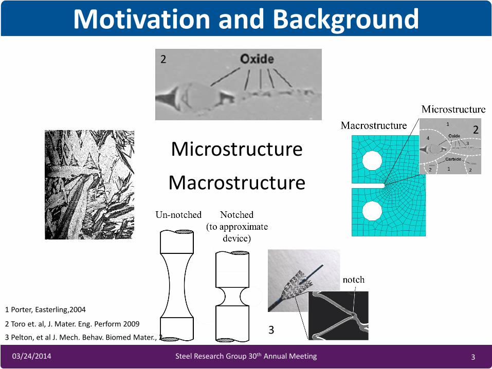
1 Porter, Easterling,2004
3 Pelton, et al J. Mech. Behav. Biomed Mater., 2008
Microstructure
Motivation and Background
2 Toro et. al, J. Mater. Eng. Perform 2009
Macrostructure
1
2
3
2
3/27/2014 4 4 03/24/2014 Steel Research Group 30th Annual Meeting
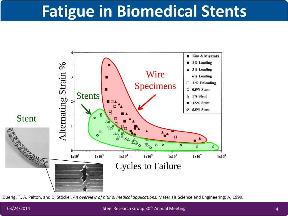
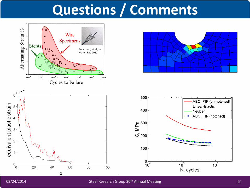
Fatigue in Biomedical Stents
Wire
Specimens Stents
Alt
ernat
ing S
trai
n %
Cycles to Failure
Duerig, T., A. Pelton, and D. Stöckel, An overview of nitinol medical applications. Materials Science and Engineering: A, 1999.
Stent
3/27/2014 5 5 03/24/2014 Steel Research Group 30th Annual Meeting
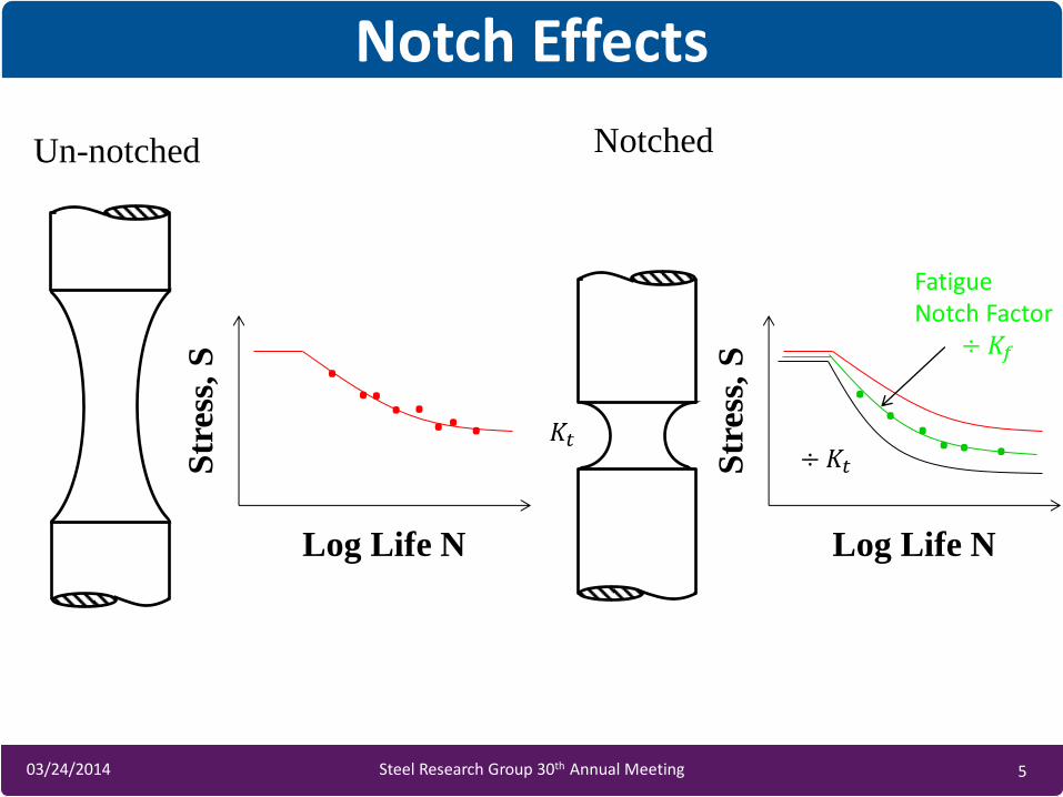
Notch Effects
Un-notched Notched
Str
ess,
S
Log Life N
. . . . . . . .
Str
ess,
S
Log Life N
. . . . . . ÷𝐾𝑡
Fatigue Notch Factor
÷ 𝐾𝑓
𝐾𝑡
3/27/2014 6 6 03/24/2014 Steel Research Group 30th Annual Meeting
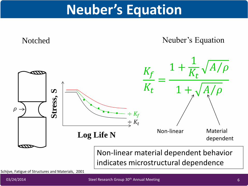
Neuber’s Equation
Notched
Str
ess,
S
Log Life N
. . . . . .
÷𝐾𝑡
𝐾𝑓
𝐾𝑡=1 +
1𝐾𝑡
𝐴 𝜌
1 + 𝐴 𝜌
Neuber’s Equation
Material dependent
Non-linear
Schijve, Fatigue of Structures and Materials, 2001
Non-linear material dependent behavior indicates microstructural dependence
𝜌 ÷ 𝐾𝑓
3/27/2014 7 7 03/24/2014 Steel Research Group 30th Annual Meeting
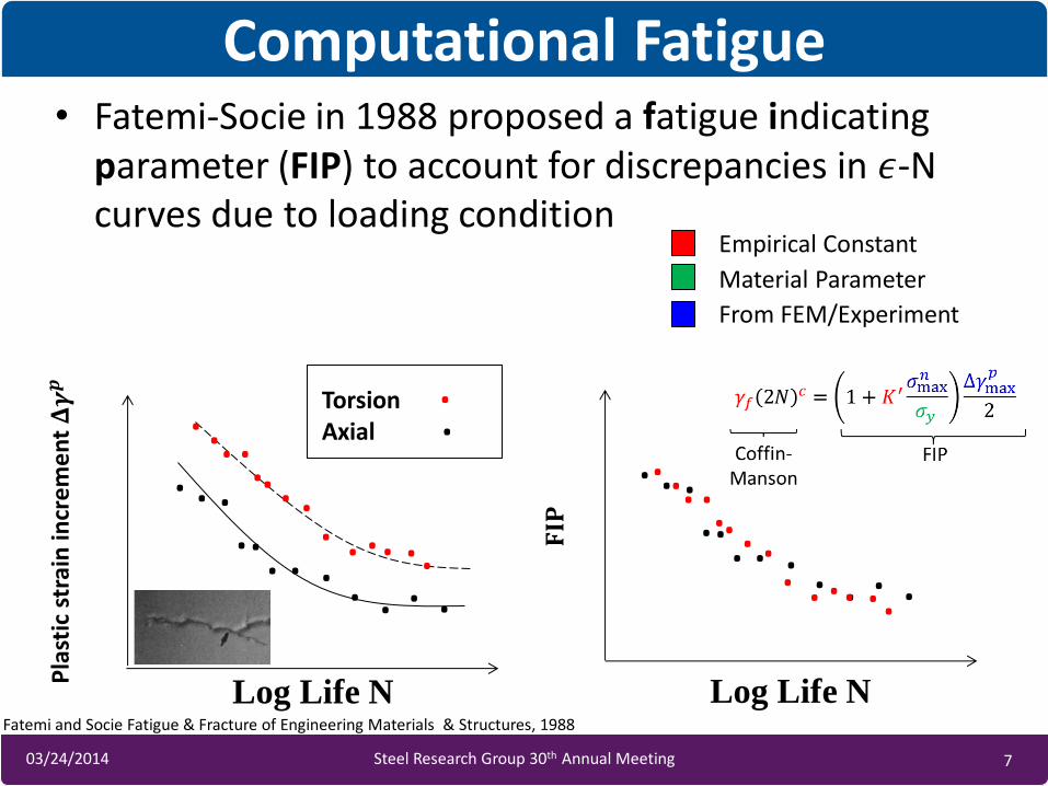
Computational Fatigue • Fatemi-Socie in 1988 proposed a fatigue indicating
parameter (FIP) to account for discrepancies in 𝜖-N curves due to loading condition
Pla
stic
str
ain
incr
em
en
t 𝚫𝜸𝒑
Torsion Axial . . . . . . . . . . . . . .
.
. . . .
. . . . . . . . . 𝐅𝐈𝐏
. . . . . . . . . . . .
. . . . . . . . . . . . . .
Empirical Constant
Material Parameter
From FEM/Experiment
Log Life N Log Life N Fatemi and Socie Fatigue & Fracture of Engineering Materials & Structures, 1988
3/27/2014 8 8 03/24/2014 Steel Research Group 30th Annual Meeting
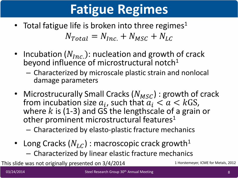
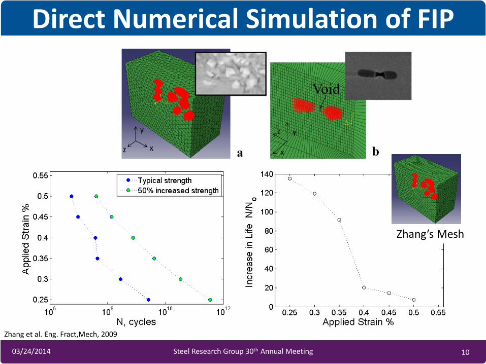
• Total fatigue life is broken into three regimes1 𝑁𝑇𝑜𝑡𝑎𝑙 = 𝑁𝐼𝑛𝑐. +𝑁𝑀𝑆𝐶 +𝑁𝐿𝐶
• Incubation (𝑁𝐼𝑛𝑐.): nucleation and growth of crack beyond influence of microstructural notch1 – Characterized by microscale plastic strain and nonlocal
damage parameters
• Microstrucurally Small Cracks (𝑁𝑀𝑆𝐶) : growth of crack from incubation size 𝑎𝑖, such that 𝑎𝑖 < 𝑎 < 𝑘GS, where 𝑘 is (1-3) and GS the lengthscale of a grain or other prominent microstructural features1 – Characterized by elasto-plastic fracture mechanics
• Long Cracks (𝑁𝐿𝐶) : macroscopic crack growth1 – Characterized by linear elastic fracture mechanics
Fatigue Regimes
This slide was not originally presented on 3/4/2014 1 Horstemeyer, ICME for Metals, 2012
3/27/2014 9 9 03/24/2014 Steel Research Group 30th Annual Meeting
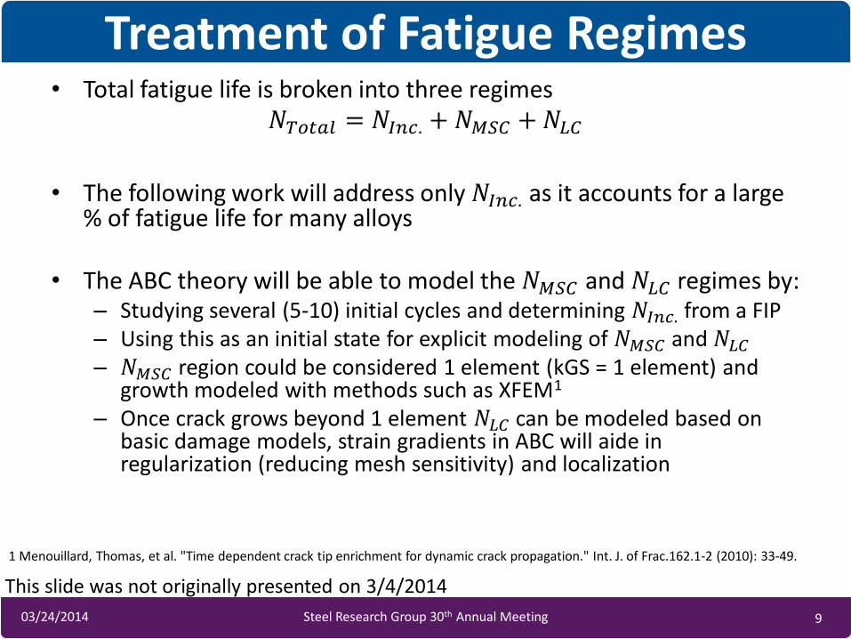
• Total fatigue life is broken into three regimes 𝑁𝑇𝑜𝑡𝑎𝑙 = 𝑁𝐼𝑛𝑐. +𝑁𝑀𝑆𝐶 +𝑁𝐿𝐶
• The following work will address only 𝑁𝐼𝑛𝑐. as it accounts for a large % of fatigue life for many alloys
• The ABC theory will be able to model the 𝑁𝑀𝑆𝐶 and 𝑁𝐿𝐶 regimes by: – Studying several (5-10) initial cycles and determining 𝑁𝐼𝑛𝑐. from a FIP – Using this as an initial state for explicit modeling of 𝑁𝑀𝑆𝐶 and 𝑁𝐿𝐶 – 𝑁𝑀𝑆𝐶 region could be considered 1 element (kGS = 1 element) and
growth modeled with methods such as XFEM1 – Once crack grows beyond 1 element 𝑁𝐿𝐶 can be modeled based on
basic damage models, strain gradients in ABC will aide in regularization (reducing mesh sensitivity) and localization
Treatment of Fatigue Regimes
This slide was not originally presented on 3/4/2014
1 Menouillard, Thomas, et al. "Time dependent crack tip enrichment for dynamic crack propagation." Int. J. of Frac.162.1-2 (2010): 33-49.
3/27/2014 10 10 03/24/2014 Steel Research Group 30th Annual Meeting
Direct Numerical Simulation of FIP
Zhang’s Mesh
Zhang et al. Eng. Fract,Mech, 2009
3/27/2014 11 11 03/24/2014 Steel Research Group 30th Annual Meeting
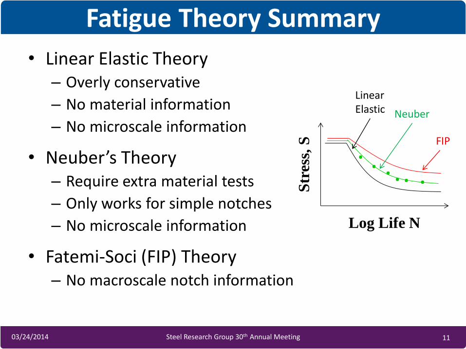
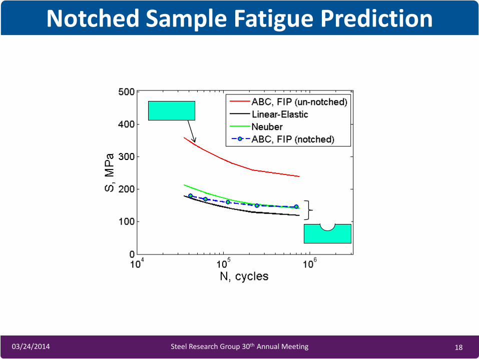
• Linear Elastic Theory – Overly conservative
– No material information
– No microscale information
• Neuber’s Theory – Require extra material tests
– Only works for simple notches
– No microscale information
• Fatemi-Soci (FIP) Theory – No macroscale notch information
Fatigue Theory Summary
Str
ess,
S
Log Life N
. . . . . .
Neuber
Linear Elastic
FIP
3/27/2014 12 12 03/24/2014 Steel Research Group 30th Annual Meeting
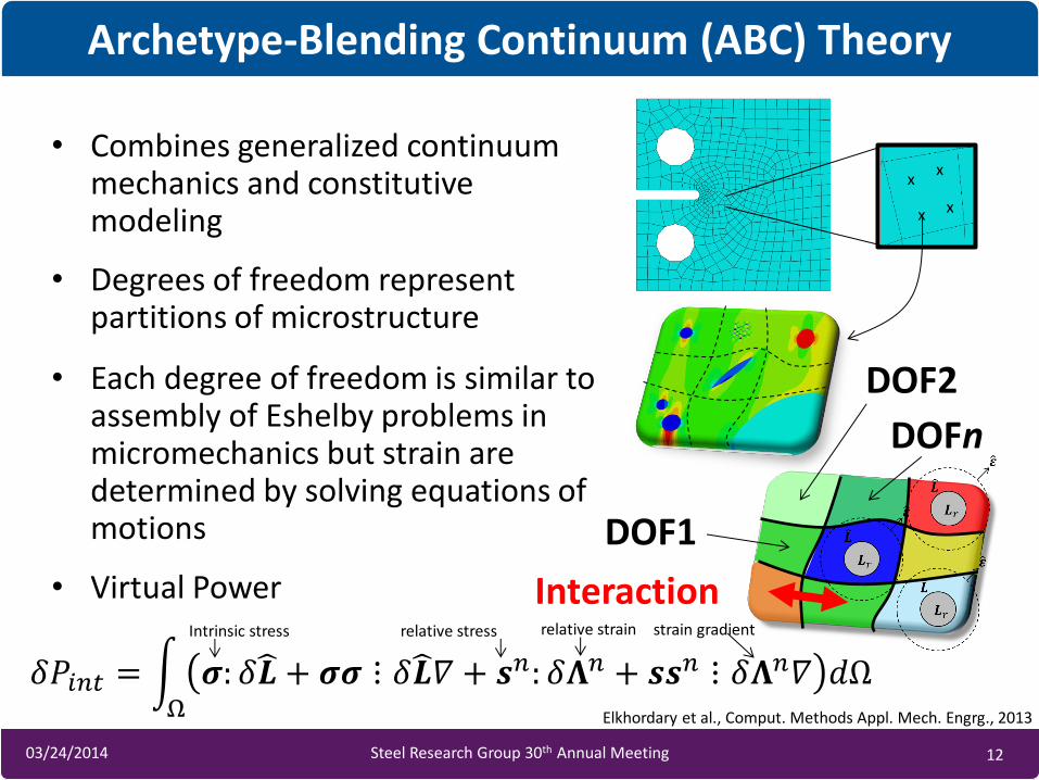
• Combines generalized continuum mechanics and constitutive modeling
• Degrees of freedom represent partitions of microstructure
• Each degree of freedom is similar to assembly of Eshelby problems in micromechanics but strain are determined by solving equations of motions
• Virtual Power
Archetype-Blending Continuum (ABC) Theory
𝛿𝑃𝑖𝑛𝑡 = 𝝈: 𝛿𝑳 + 𝝈𝝈 ⋮ 𝛿𝑳 𝛻 + 𝒔𝑛: 𝛿𝚲𝑛 + 𝒔𝒔𝑛 ⋮ 𝛿𝚲𝑛𝛻 𝑑Ω Ω
x x
x x
DOF1
DOF2
DOFn
Interaction relative strain relative stress Intrinsic stress strain gradient
Elkhordary et al., Comput. Methods Appl. Mech. Engrg., 2013
3/27/2014 13 13 03/24/2014 Steel Research Group 30th Annual Meeting
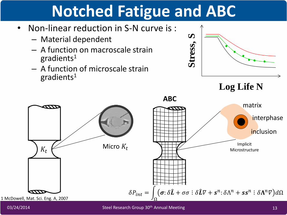
• Non-linear reduction in S-N curve is : – Material dependent – A function on macroscale strain
gradients1 – A function of microscale strain
gradients1
Notched Fatigue and ABC
Str
ess,
S
Log Life N
. . . . . .
𝐾𝑡 Micro 𝐾𝑡
ABC
Implicit Microstructure
𝛿𝑃𝑖𝑛𝑡 = 𝝈: 𝛿𝑳 + 𝜎𝜎 ⋮ 𝛿𝑳 𝛻 + 𝒔𝑛: 𝛿Λ𝑛 + 𝒔𝒔𝑛 ⋮ 𝛿𝚲𝑛𝛻 𝑑Ω Ω
matrix
interphase
inclusion
1 McDowell, Mat. Sci. Eng. A, 2007
3/27/2014 14 14 03/24/2014 Steel Research Group 30th Annual Meeting
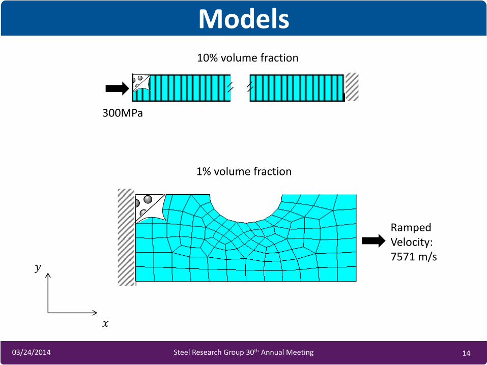
Models
300MPa
Ramped Velocity: 7571 m/s
10% volume fraction
1% volume fraction
𝑥
𝑦
3/27/2014 15 15 03/24/2014 Steel Research Group 30th Annual Meeting
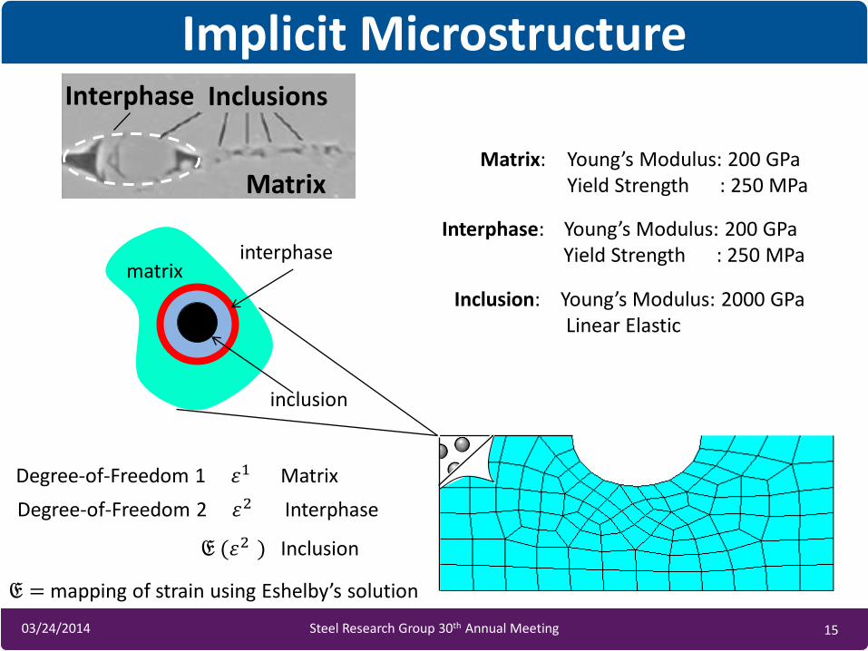
Implicit Microstructure
Matrix: Young’s Modulus: 200 GPa Yield Strength : 250 MPa
Interphase: Young’s Modulus: 200 GPa Yield Strength : 250 MPa
Inclusion: Young’s Modulus: 2000 GPa Linear Elastic
Degree-of-Freedom 1 휀1 Matrix
Degree-of-Freedom 2 휀2 Interphase
𝔈 (휀2 ) Inclusion
𝔈 = mapping of strain using Eshelby’s solution
interphase
inclusion
matrix
Matrix
Interphase Inclusions
3/27/2014 16 16 03/24/2014 Steel Research Group 30th Annual Meeting
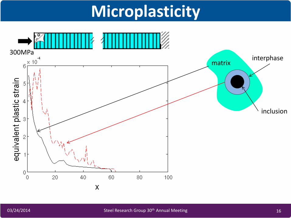
Microplasticity
matrix interphase
inclusion
300MPa
3/27/2014 17 17 03/24/2014 Steel Research Group 30th Annual Meeting
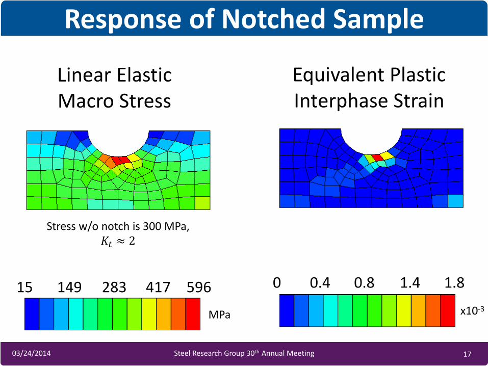
Response of Notched Sample
15 149 283 417 596
MPa
0 0.4 0.8 1.4 1.8
x10-3
Linear Elastic Macro Stress
Equivalent Plastic Interphase Strain
Stress w/o notch is 300 MPa, 𝐾𝑡 ≈ 2
3/27/2014 18 18 03/24/2014 Steel Research Group 30th Annual Meeting
Notched Sample Fatigue Prediction
3/27/2014 19 19 03/24/2014 Steel Research Group 30th Annual Meeting
• ABC uses a multiscale multicomponent formulation rooted in micromechanics to predict material behavior
• ABC can predicted notch sensitivity of notched devices, giving information of geometric effects and statistics
• Goal is that device designers can optimize microstructure and geometry concurrently
Summary and Conclusions
3/27/2014 20 20 03/24/2014 Steel Research Group 30th Annual Meeting
Questions / Comments
Robertson, et al., Int. Mater. Rev 2012
3/27/2014 21 21 03/24/2014 Steel Research Group 30th Annual Meeting
Backup
3/27/2014 22 22 03/24/2014 Steel Research Group 30th Annual Meeting
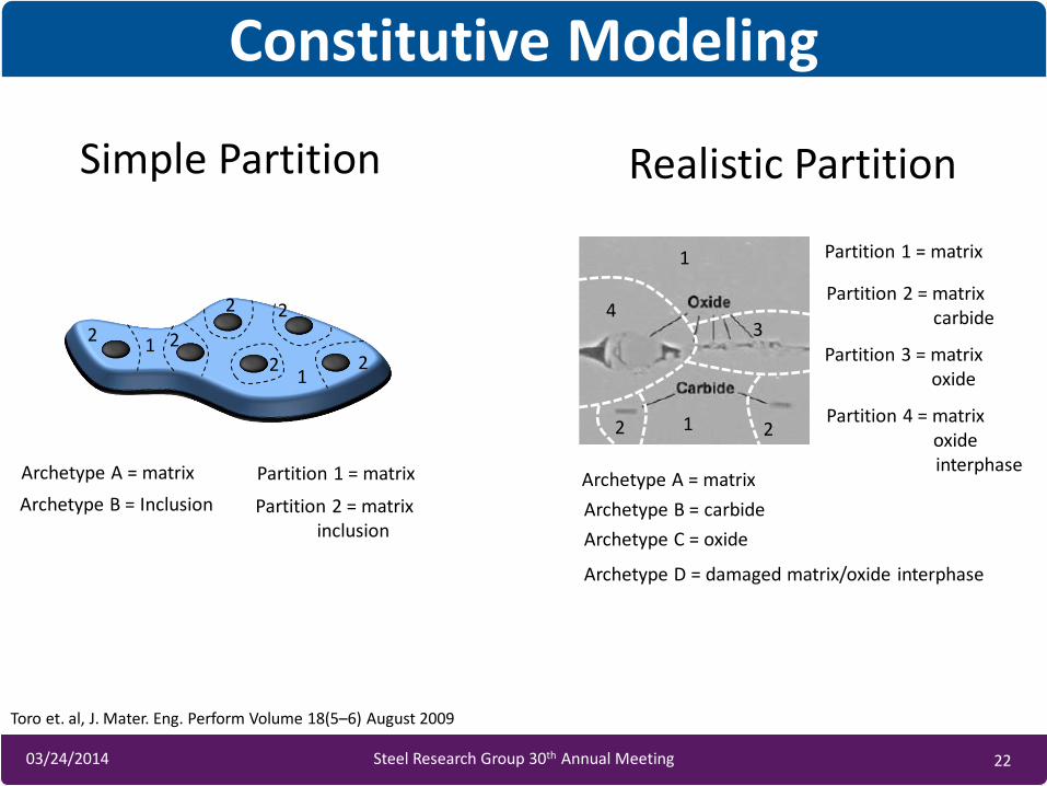
Constitutive Modeling
2
Archetype A = matrix
Archetype B = Inclusion
Partition 1 = matrix
Partition 2 = matrix inclusion
1
Simple Partition
2 2
2 2
2 2 1
Realistic Partition
1
2
3 4
2 1
Archetype A = matrix
Archetype B = carbide
Archetype C = oxide
Archetype D = damaged matrix/oxide interphase
Partition 1 = matrix
Partition 2 = matrix carbide
Partition 3 = matrix oxide
Partition 4 = matrix oxide interphase
Toro et. al, J. Mater. Eng. Perform Volume 18(5–6) August 2009
3/27/2014 23 23 03/24/2014 Steel Research Group 30th Annual Meeting
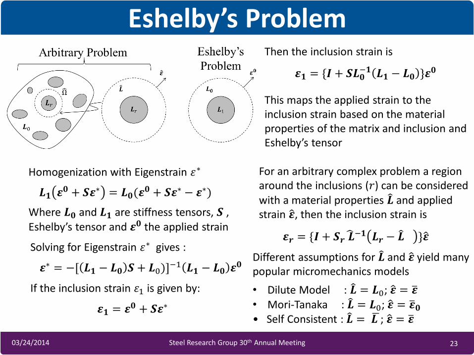
Eshelby’s Problem
Homogenization with Eigenstrain 휀∗
𝑳𝟏 𝜺𝟎 + 𝑺𝜺∗ = 𝑳𝟎(𝜺𝟎 + 𝑺𝜺∗ − 𝜺∗)
Where 𝑳𝟎 and 𝑳𝟏 are stiffness tensors, 𝑺 , Eshelby’s tensor and 𝜺𝟎 the applied strain
Solving for Eigenstrain 휀∗ gives :
𝜺∗ = −[ 𝑳𝟏 − 𝑳𝟎 𝑺 + 𝑳0)]−1 𝑳𝟏 − 𝑳𝟎 𝜺𝟎
If the inclusion strain 휀1 is given by:
𝜺𝟏 = {𝑰 + 𝑺𝑳𝟎−𝟏 𝑳𝟏 − 𝑳𝟎 }𝜺𝟎
Then the inclusion strain is
This maps the applied strain to the inclusion strain based on the material properties of the matrix and inclusion and Eshelby’s tensor
For an arbitrary complex problem a region around the inclusions (𝑟) can be considered with a material properties 𝑳 and applied strain 𝜺 , then the inclusion strain is
𝜺𝒓 = {𝑰 + 𝑺𝒓 𝑳 −𝟏 𝑳𝒓 − 𝑳 }𝜺
𝜺𝟏 = 𝜺𝟎 + 𝑺𝜺∗
• Dilute Model : 𝑳 = 𝑳0; 𝜺 = 𝜺 • Mori-Tanaka : 𝑳 = 𝑳0; 𝜺 = 𝜺 𝟎 • Self Consistent : 𝑳 = 𝑳 ; 𝜺 = 𝜺
Different assumptions for 𝑳 and 𝜺 yield many popular micromechanics models