
Application of Industrial Heat Pumps - トップページ Final Report_Task3.pdf · Application of...
178
Application of Industrial Heat Pumps IEA Industrial Energy-related Systems and Technologies Annex 13 IEA Heat Pump Programme Annex 35 Task 3: R&D Projects Final Report (Status: 10.06.2014) Prepared by the Participants of Annex 35/13
Transcript of Application of Industrial Heat Pumps - トップページ Final Report_Task3.pdf · Application of...
AApplication of IIndustrial Heat Pumps
IEA Industrial Energy-related Systems and Technologies Annex 13
IEA Heat Pump Programme Annex 35
Task 3:R&D Projects
Final Report
(Status: 10.06.2014)
Prepared by the
Participants of Annex 35/13

Contents
1 Summary ..................................................................................... 1-229
2 Introduction .................................................................................. 2-234
3 Austria .......................................................................................... 3-235
3.1 Industrial heat pumping systems available in Austria ................. 3-235 3.2 R&D projects in Austria ............................................................... 3-238
3.2.1 Hybrid (absorption/compression) heat pumping systems . 3-238
3.2.2 Absorption heat pumping systems .................................... 3-242
3.2.3 HPs for upgrading flue gas condensation heat.................. 3-245
3.3 Literature ..................................................................................... 3-246
4 Canada ........................................................................................ 4-248
4.1 Introduction ................................................................................. 4-248 4.2 Historical background .................................................................. 4-249 4.3 Canada’s R&D projects ................................................................ 4-249
4.3.1 Thermally-driven ejector heat pumps ................................ 4-251
4.3.2 CO2 ejector refrigeration system ........................................ 4-254
4.3.3 High-temperature heat pumps .......................................... 4-257
4.4 References ................................................................................... 4-274
5 Denmark ....................................................................................... 5-278
5.1 Introduction ................................................................................. 5-278 5.2 Ongoing R&D ............................................................................... 5-279 5.3 Demonstration ............................................................................ 5-280
5.3.1 Energy efficient drying with a novel turbo compressor based high temperature heat pump .................................. 5-281
5.3.2 Development of ultra high temperature hybrid heat pump for industrial processes ...................................................... 5-293
5.3.3 Highly efficient Thermodynamic Cycle with Isolated System Energy Charging (ISEC) .......................................... 5-296
5.4 Economy and other incentives .................................................... 5-297
6 France ......................................................................................... 6-298
6.1 Introduction ................................................................................. 6-298 6.2 The French industry ..................................................................... 6-299 6.3 The temperature level ................................................................. 6-299 6.4 Heat pumps in France: maturity, fluids and technology ............. 6-301 6.5 EDF R&D activities ....................................................................... 6-302 6.6 Current and future activities ....................................................... 6-302
6.7 Experimental test bench at EDF R&D .......................................... 6-302 6.8 Technical partnership: EDF & Johnson Controls ......................... 6-303
6.8.1 Description of the heat pump ............................................ 6-304
6.8.2 Results and performances ................................................. 6-305
6.9 Altereco project ........................................................................... 6-306 6.9.1 Description of the heat pump ............................................ 6-306
6.9.2 Results and performances ................................................. 6-308
6.10 PACO Project ............................................................................... 6-309 6.11 Prospects ..................................................................................... 6-310
7 Germany ..................................................................................... 7-312
7.1 Institut für Energiewirtschaft und Rationelle Energieanwendung, Universität Stuttgart ...................................... 7-312
7.1.1 Advances in the development of industrial heat pumps ... 7-312
7.1.2 Development and application of an industrial high temperature heat pump using R245fa ............................... 7-314
7.1.3 References ......................................................................... 7-321
7.2 thermea Energiesysteme ............................................................ 7-322 7.2.1 How to come up to high supply temperatures .................. 7-322
7.2.2 CO2 as refrigerant in high temperature heat pumps ......... 7-324
7.2.3 thermea's CO2 heat pump series thermeco2 ...................... 7-324
7.2.4 Summery ............................................................................ 7-328
7.2.5 Literature ........................................................................... 7-328
8 Japan ........................................................................................... 8-329
8.1 Overview of industrial heat pump technology in Japan .............. 8-329 8.1.1 Introduction ....................................................................... 8-329
8.1.2 General types of industrial heat pumps ............................. 8-329
8.1.3 Thermodynamic cycles of high-temperature heat pumps . 8-331
8.1.4 Technologies required for industrial heat pumps .............. 8-334
8.1.5 References ......................................................................... 8-335
8.2 High Temperature Heat Pump .................................................... 8-335 8.2.1 DUAL-CYCLE HEAT PUMP WATER HEATER
(AIR-TO-WATER) ................................................................. 8-335
8.2.2 CO2HEAT PUMP AIR HEATER (WATER-TO-AIR) .................. 8-339
8.2.3 HEAT PUMP STEAM SUPPLIER (WATER-TO-WATER) ......... 8-345
8.2.4 HEAT PUMP FOR CIRCULATIONG WATER HEATING (AIR-TO-WATER) ................................................................. 8-348
8.2.5 WASTE HEAT RECOVERY HEAT PUMP WATER HEATER ..... 8-353
8.3 Survey of low GWP refrigerants for high temperature heat pumps and basic analysis on their thermodynamic cycle performance ................................................................................... 8-357
8.3.1 Introduction ....................................................................... 8-357
8.3.2 Basic characteristics of refrigerants suitable for high temperature heat pump ..................................................... 8-357
8.3.3 Thermodynamic analysis of cycle performance ................. 8-360
8.3.4 Concluding remarks ........................................................... 8-363
8.4 Industrial Application of Thermal Storage Technologies ............ 8-364 8.4.1 Ice slurry made from trehalose aqueous solution ............. 8-364
8.4.2 Tetra-n-butyl ammonium bromide (TBAB) hydrate slurry . 8-365
8.4.3 Paraffin slurry .................................................................... 8-367
8.4.4 Sodium acetate trihydrate: CH3COONa·3H2O .................... 8-368
8.4.5 Erythritol: (HOCH2 [CH(OH)2]2CH2OH) and Mannitol: (HOCH2(CHOH)4 CH2OH .................................................. 8-369
8.4.6 Other thermal technologies ............................................... 8-369
9 Korea ............................................................................................ 9-371
9.1 R&D Background of industrial heat pumps ................................. 9-371 9.2 R&D programs of Korea ............................................................... 9-372 9.3 Heat pump R&D cases ................................................................. 9-373
9.3.1 Development of a 30 kW grade compression/absorption heat pump producing high temperature hot water with waste heat .......................................................................... 9-373
9.3.2 Demonstration of a high-temperature heat pump system with heat recovery from flue gases ................................... 9-374
9.3.3 High-temperature heat pump for commercial drying process ............................................................................... 9-376
9.3.4 Geothermal heat pump system using R410A centrifugal compressor ......................................................................... 9-377
9.3.5 Double effect absorption heat pump development for low-temperature sewage waste heat recovery ........................ 9-378
9.3.6 Development of hybrid water source heat pump using solar heat ........................................................................... 9-378
9.3.7 Demonstration of a geothermal heat pump system and ground heat exchangers which are installed to the substructure of buildings .................................................... 9-379
9.3.8 Technology development for vertical closed type direct exchange (DX) geothermal heat pump system .................. 9-380
10 The Netherlands ....................................................................... 10-382
10.1 TKI- ISPT Innovation Program .................................................... 10-382
10.2 European Technology Platform on Renewable Heating and Cooling (RHC-Platform) ............................................................. 10-384
10.3 Technological developments ..................................................... 10-388 10.3.1 CO2 – Heat Pump..................................................... 10-388
10.3.2 n-Butane heat pump ............................................... 10-389
10.3.3 New refrigerants ..................................................... 10-390
10.4 Running R&D Projects ............................................................... 10-392 10.4.1 Thermo Acoustic Heat Pump .................................. 10-392
10.4.2 Hybrid Systems ....................................................... 10-395
10.4.3 Electrically and gas fired thermoacoustic systems . 10-397
10.4.4 Minichannel heat exchangers for compression resorption heat pumps ........................................... 10-398
10.5 Heat Integrated Distillation Columns ........................................ 10-399 10.6 Literature ................................................................................... 10-400
Task 3: R&D Projects
Summary
1-229
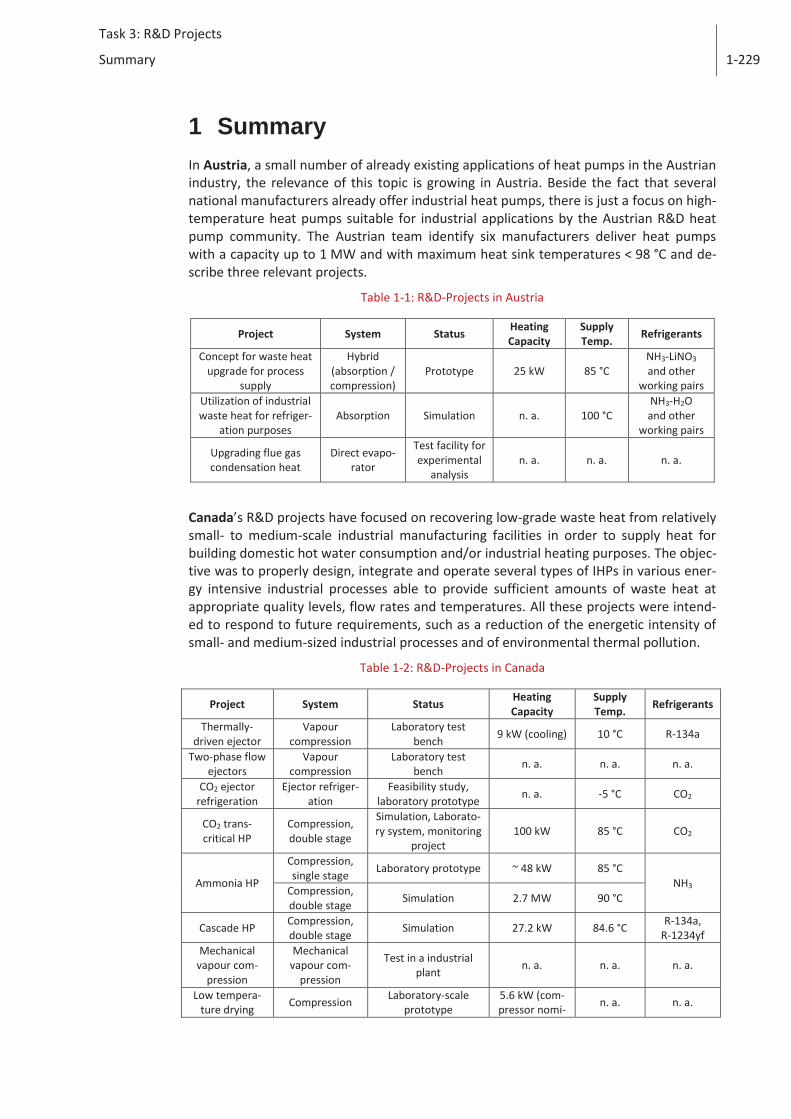
1 Summary In Austria, a small number of already existing applications of heat pumps in the Austrian industry, the relevance of this topic is growing in Austria. Beside the fact that several national manufacturers already offer industrial heat pumps, there is just a focus on high-temperature heat pumps suitable for industrial applications by the Austrian R&D heat pump community. The Austrian team identify six manufacturers deliver heat pumps with a capacity up to 1 MW and with maximum heat sink temperatures < 98 °C and de-scribe three relevant projects.
Table 1-1: R&D-Projects in Austria
Project System Status Heating Capacity
Supply Temp.
Refrigerants
Concept for waste heat upgrade for process
supply
Hybrid (absorption / compression)
Prototype 25 kW 85 °C NH3-LiNO3 and other
working pairs Utilization of industrial waste heat for refriger-
ation purposes Absorption Simulation n. a. 100 °C
NH3-H2O and other
working pairs
Upgrading flue gas condensation heat
Direct evapo-rator
Test facility for experimental
analysis n. a. n. a. n. a.
Canada’s R&D projects have focused on recovering low-grade waste heat from relatively small- to medium-scale industrial manufacturing facilities in order to supply heat for building domestic hot water consumption and/or industrial heating purposes. The objec-tive was to properly design, integrate and operate several types of IHPs in various ener-gy intensive industrial processes able to provide sufficient amounts of waste heat at appropriate quality levels, flow rates and temperatures. All these projects were intend-ed to respond to future requirements, such as a reduction of the energetic intensity of small- and medium-sized industrial processes and of environmental thermal pollution.
Table 1-2: R&D-Projects in Canada
Project System Status Heating Capacity
Supply Temp.
Refrigerants
Thermally-driven ejector
Vapour compression
Laboratory test bench
9 kW (cooling) 10 °C R-134a
Two-phase flow ejectors
Vapour compression
Laboratory test bench
n. a. n. a. n. a.
CO2 ejector refrigeration
Ejector refriger-ation
Feasibility study, laboratory prototype
n. a. -5 °C CO2
CO2 trans-critical HP
Compression, double stage
Simulation, Laborato-ry system, monitoring
project 100 kW 85 °C CO2
Ammonia HP
Compression, single stage
Laboratory prototype ~ 48 kW 85 °C NH3
Compression, double stage
Simulation 2.7 MW 90 °C
Cascade HP Compression, double stage
Simulation 27.2 kW 84.6 °C R-134a, R-1234yf
Mechanical vapour com-
pression
Mechanical vapour com-
pression
Test in a industrial plant
n. a. n. a. n. a.
Low tempera-ture drying
Compression Laboratory-scale prototype
5.6 kW (com-pressor nomi-
n. a. n. a.
Task 3: R&D Projects
Summary
1-230
nal power input)
High tempera-ture drying
Compression Industrial-scale pro-
totype (2 units)
65 kW (com-pressor nomi-
nal power input)
n. a. R-236fa
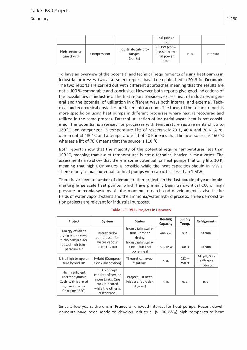
To have an overview of the potential and technical requirements of using heat pumps in industrial processes, two assessment reports have been published in 2013 for Denmark. The two reports are carried out with different approaches meaning that the results are not a 100 % comparable and conclusive. However both reports give good indications of the possibilities in industries. The first report considers excess heat of industries in gen-eral and the potential of utilization in different ways both internal and external. Tech-nical and economical obstacles are taken into account. The focus of the second report is more specific on using heat pumps in different processes where heat is recovered and utilized in the same process. External utilization of industrial waste heat is not consid-ered. The potential is assessed for processes with temperature requirements of up to 180 °C and categorized in temperature lifts of respectively 20 K, 40 K and 70 K. A re-quirement of 180° C and a temperature lift of 20 K means that the heat source is 160 °C whereas a lift of 70 K means that the source is 110 °C.
Both reports show that the majority of the potential require temperatures less than 100 °C, meaning that outlet temperatures is not a technical barrier in most cases. The assessments also show that there is some potential for heat pumps that only lifts 20 K, meaning that high COP values is possible while the heat capacities should in MW’s. There is only a small potential for heat pumps with capacities less than 1 MW.
There have been a number of demonstration projects in the last couple of years imple-menting large scale heat pumps, which have primarily been trans-critical CO2 or high pressure ammonia systems. At the moment research and development is also in the fields of water vapor systems and the ammonia/water hybrid process. Three demonstra-tion projects are relevant for industrial purposes.
Table 1-3: R&D-Projects in Denmark
Project System Status Heating Capacity
Supply Temp.
Refrigerants
Energy efficient drying with a novel turbo compressor based high tem-
perature HP
Rotrex turbo compressor for water vapour compression
Industrial installa-tion – timber
drying 446 kW n. a. Steam
Industrial installa-tion – fish and
bone meal ~2.2 MW 100 °C Steam
Ultra high tempera-ture hybrid HP
Hybrid (Compres-sion / absorption)
Theoretical inves-tigations
n. a. 180 – 250 °C
NH3-H2O in different mixtures
Highly efficient Thermodynamic
Cycle with Isolated System Energy Charging (ISEC)
ISEC concept consists of two or more tanks. One
tank is heated while the other is
discharged.
Project just been initiated (duration
3 years) n. a. n. a. n. a.
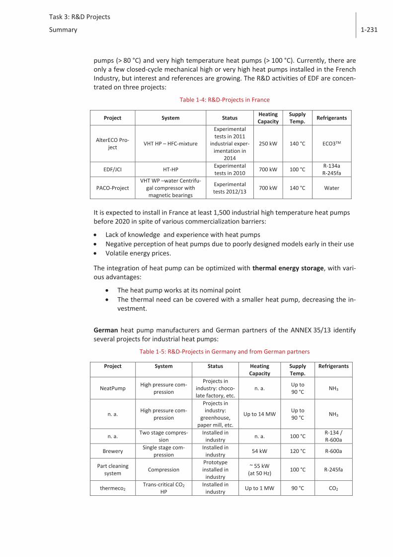
Since a few years, there is in France a renewed interest for heat pumps. Recent devel-opments have been made to develop industrial (> 100 kWth) high temperature heat
Task 3: R&D Projects
Summary
1-231
pumps (> 80 °C) and very high temperature heat pumps (> 100 °C). Currently, there are only a few closed-cycle mechanical high or very high heat pumps installed in the French Industry, but interest and references are growing. The R&D activities of EDF are concen-trated on three projects:
Table 1-4: R&D-Projects in France
Project System Status Heating Capacity
Supply Temp. Refrigerants
AlterECO Pro-ject
VHT HP – HFC-mixture
Experimental tests in 2011
industrial exper-imentation in
2014
250 kW 140 °C ECO3TM
EDF/JCI HT-HP Experimental tests in 2010
700 kW 100 °C R-134a R-245fa
PACO-Project VHT WP –water Centrifu-
gal compressor with magnetic bearings
Experimental tests 2012/13
700 kW 140 °C Water
It is expected to install in France at least 1,500 industrial high temperature heat pumps before 2020 in spite of various commercialization barriers:
Lack of knowledge and experience with heat pumps Negative perception of heat pumps due to poorly designed models early in their use Volatile energy prices.
The integration of heat pump can be optimized with thermal energy storage, with vari-ous advantages:
The heat pump works at its nominal point The thermal need can be covered with a smaller heat pump, decreasing the in-
vestment.
German heat pump manufacturers and German partners of the ANNEX 35/13 identify several projects for industrial heat pumps:
Table 1-5: R&D-Projects in Germany and from German partners
Project System Status Heating Capacity
Supply Temp.
Refrigerants
NeatPump High pressure com-
pression
Projects in industry: choco-late factory, etc.
n. a. Up to 90 °C
NH3
n. a. High pressure com-
pression
Projects in industry:
greenhouse, paper mill, etc.
Up to 14 MW Up to 90 °C
NH3
n. a. Two stage compres-
sion Installed in
industry n. a. 100 °C R-134 / R-600a
Brewery Single stage com-
pression Installed in
industry 54 kW 120 °C R-600a
Part cleaning system
Compression Prototype installed in
industry
~ 55 kW (at 50 Hz)
100 °C R-245fa
thermeco2 Trans-critical CO2
HP Installed in
industry Up to 1 MW 90 °C CO2
Task 3: R&D Projects
Summary
1-232
Research on new refrigerants for high temperature application is also done in Germany. The promising candidates are called LG6 and MF2.
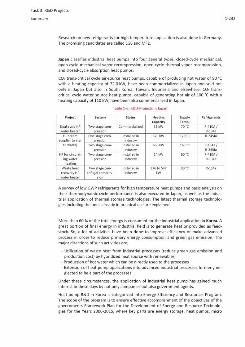
Japan classifies industrial heat pumps into four general types: closed-cycle mechanical, open-cycle mechanical vapor recompression, open-cycle thermal vapor recompression, and closed-cycle absorption heat pumps.
CO2 trans-critical cycle air-source heat pumps, capable of producing hot water of 90 °C with a heating capacity of 72.0 kW, have been commercialized in Japan and sold not only in Japan but also in South Korea, Taiwan, Indonesia and elsewhere. CO2 trans-critical cycle water source heat pumps, capable of generating hot air of 100 °C with a heating capacity of 110 kW, have been also commercialized in Japan.
Table 1-6: R&D-Projects in Japan
Project System Status Heating Capacity
Supply Temp.
Refrigerants
Dual-cycle HP water heater
Two stage com-pression
Commercialized 35 kW 70 °C R-410A / R-134a
HP steam supplier (water
to water)
One stage com-pression
Installed in industry
370 kW 120 °C R-245fa
Two stage com-pression
Installed in industry
660 kW 165 °C R-134a / R-245fa
HP for circulat-ing water heating
Two stage com-pression
Installed in industry
14 kW 90 °C R-410A / R-134a
Waste heat recovery HP water heater
two stage cen-trifugal compres-
sion
Installed in industry
376 to 547 kW
90 °C R-134a
A survey of low GWP refrigerants for high temperature heat pumps and basic analysis on their thermodynamic cycle performance is also executed in Japan, as well as the indus-trial application of thermal storage technologies. The latest thermal storage technolo-gies including the ones already in practical use are explained.
More than 60 % of the total energy is consumed for the industrial application in Korea. A great portion of final energy in industrial field is to generate heat or provided as feed-stock. So, a lot of activities have been done to improve efficiency or make advanced process in order to reduce primary energy consumption and green gas emission. The major directions of such activities are;
- Utilization of waste heat from industrial processes (reduce green gas emission and production cost) by hybridized heat source with renewables
- Production of hot water which can be directly used to the processes - Extension of heat pump applications into advanced industrial processes formerly ne-
glected to be a part of the processes
Under these circumstances, the application of industrial heat pump has gained much interest in these days by not only companies but also government agents.
Heat pump R&D in Korea is categorized into Energy Efficiency and Resources Program. The scope of the program is to ensure effective accomplishment of the objectives of the governments Framework Plan for the Development of Energy and Resource Technolo-gies for the Years 2006-2015, where key parts are energy storage, heat pumps, micro
Task 3: R&D Projects
Summary
1-233
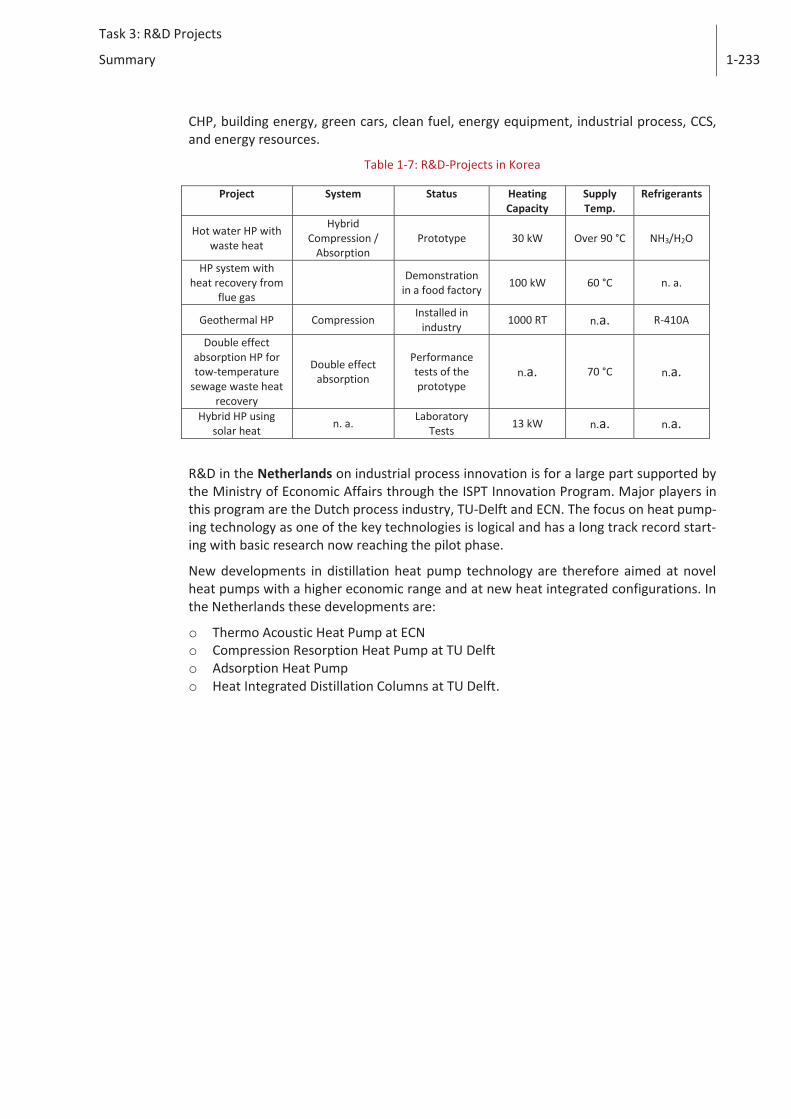
CHP, building energy, green cars, clean fuel, energy equipment, industrial process, CCS, and energy resources.
Table 1-7: R&D-Projects in Korea
Project System Status Heating Capacity
Supply Temp.
Refrigerants
Hot water HP with waste heat
Hybrid Compression /
Absorption Prototype 30 kW Over 90 °C NH3/H2O
HP system with heat recovery from
flue gas
Demonstration in a food factory
100 kW 60 °C n. a.
Geothermal HP Compression Installed in
industry 1000 RT n.a. R-410A
Double effect absorption HP for tow-temperature
sewage waste heat recovery
Double effect absorption
Performance tests of the prototype
n.a. 70 °C n.a.
Hybrid HP using solar heat
n. a. Laboratory
Tests 13 kW n.a. n.a.
R&D in the Netherlands on industrial process innovation is for a large part supported by the Ministry of Economic Affairs through the ISPT Innovation Program. Major players in this program are the Dutch process industry, TU-Delft and ECN. The focus on heat pump-ing technology as one of the key technologies is logical and has a long track record start-ing with basic research now reaching the pilot phase.
New developments in distillation heat pump technology are therefore aimed at novel heat pumps with a higher economic range and at new heat integrated configurations. In the Netherlands these developments are:
o Thermo Acoustic Heat Pump at ECN o Compression Resorption Heat Pump at TU Delft o Adsorption Heat Pump o Heat Integrated Distillation Columns at TU Delft.
Task 3: R&D Projects
Introduction
2-234
2 Introduction
One of the major programs of the IEA HPP IETS Annex "Application of industrial Heat Pumps" is to develop and advance heat pump technology to support industry to use its energy resources more efficiently. It involves using heat pumps in a role of both increas-ing the process efficiencies and recovering and reusing waste energy emitted in indus-trial manufacturing processes. It should foster research, development and prototype tests for more efficient and economical recovery of waste energy in industry, the identi-fication of appropriate heat pump applications within the industrial sector and the sub-sequent development of heat pump technologies to meet the industrial requirements. In addition to system studies, high temperature heat pumps, including refrigerant and component developmental programs should be supported that would potentially result in enhanced performance and reduced costs.
The following R&D projects in the participating countries/organisations are of interest for the annex:
Task 3: R&D Projects
Austria
3-235
3 Austria
Despite a small number of already existing applications of heat pumps in the Austrian industry, the relevance of this topic is growing in Austria. Beside the fact that several national manufacturers already offer industrial heat pumps (see chapter 3.1), there is just a focus on high-temperature heat pumps suitable for industrial applications by the Austrian R&D heat pump community (see chapter 3.2)
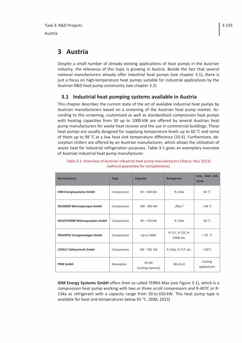
3.1 Industrial heat pumping systems available in Austria This chapter describes the current state of the art of available industrial heat pumps by Austrian manufacturers based on a screening of the Austrian heat pump market. Ac-cording to this screening, customized as well as standardized compression heat pumps with heating capacities from 50 up to 1000 kW are offered by several Austrian heat pump manufacturers for waste heat recover and the use in commercial buildings. These heat pumps are usually designed for supplying temperature levels up to 60 °C and some of them up to 98 °C at a low heat sink temperature difference (10 K). Furthermore, ab-sorption chillers are offered by an Austrian manufacturer, which allows the utilization of waste heat for industrial refrigeration purposes. Table 3-1 gives an exemplary overview of Austrian industrial heat pump manufacturer.
Table 3-1: Overview of Austrian industrial heat pump manufacturers (Status: Nov 2013) (without guarantee for completeness)
Manufacturer Type Capacity Refrigerant max. heat sink
temp.
IDM-Energiesysteme GmbH Compression 50 – 500 kW R-134a 65 °C
OCHSNER Wärmepumpen GmbH Compression 100 - 300 kW „Öko1“ < 98 °C
HELIOTHERM Wärmepumpen GmbH Compression 49 – 134 kW R-134a 60 °C
FRIGOPOL Energieanlagen GmbH Compression Up to 1MW R-717, R-723, R-
236fa etc. > 70 °C
COFELY Kältetechnik GmbH Compression 100 - 700 kW R-134a, R-717, etc. < 80°C
PINK GmbH Absorption 20 kW
(cooling capacity) NH3/H2O
Cooling
applications
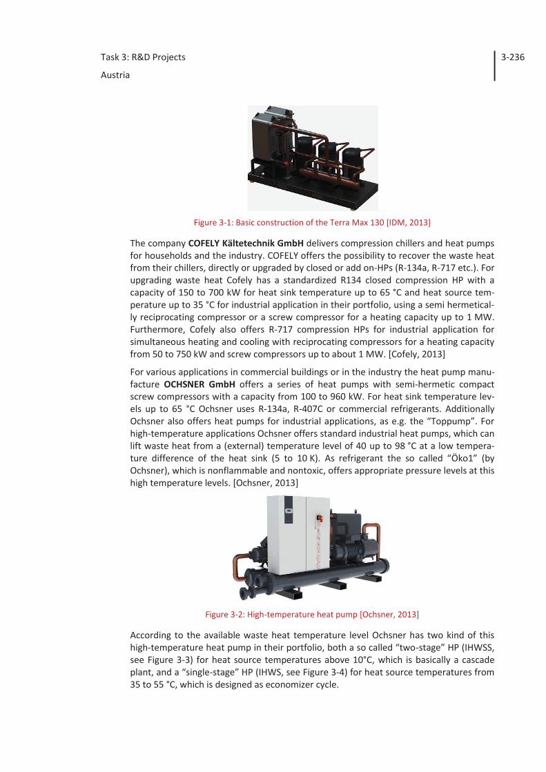
IDM Energy Systems GmbH offers their so called TERRA Max (see Figure 3-1), which is a compression heat pump working with two or three scroll compressors and R-407C or R-134a as refrigerant with a capacity range from 50 to 650 kW. This heat pump type is available for heat sink temperatures below 65 °C. [IDM, 2013]
Task 3: R&D Projects
Austria
3-236
Figure 3-1: Basic construction of the Terra Max 130 [IDM, 2013]
The company COFELY Kältetechnik GmbH delivers compression chillers and heat pumps for households and the industry. COFELY offers the possibility to recover the waste heat from their chillers, directly or upgraded by closed or add on-HPs (R-134a, R-717 etc.). For upgrading waste heat Cofely has a standardized R134 closed compression HP with a capacity of 150 to 700 kW for heat sink temperature up to 65 °C and heat source tem-perature up to 35 °C for industrial application in their portfolio, using a semi hermetical-ly reciprocating compressor or a screw compressor for a heating capacity up to 1 MW. Furthermore, Cofely also offers R-717 compression HPs for industrial application for simultaneous heating and cooling with reciprocating compressors for a heating capacity from 50 to 750 kW and screw compressors up to about 1 MW. [Cofely, 2013]
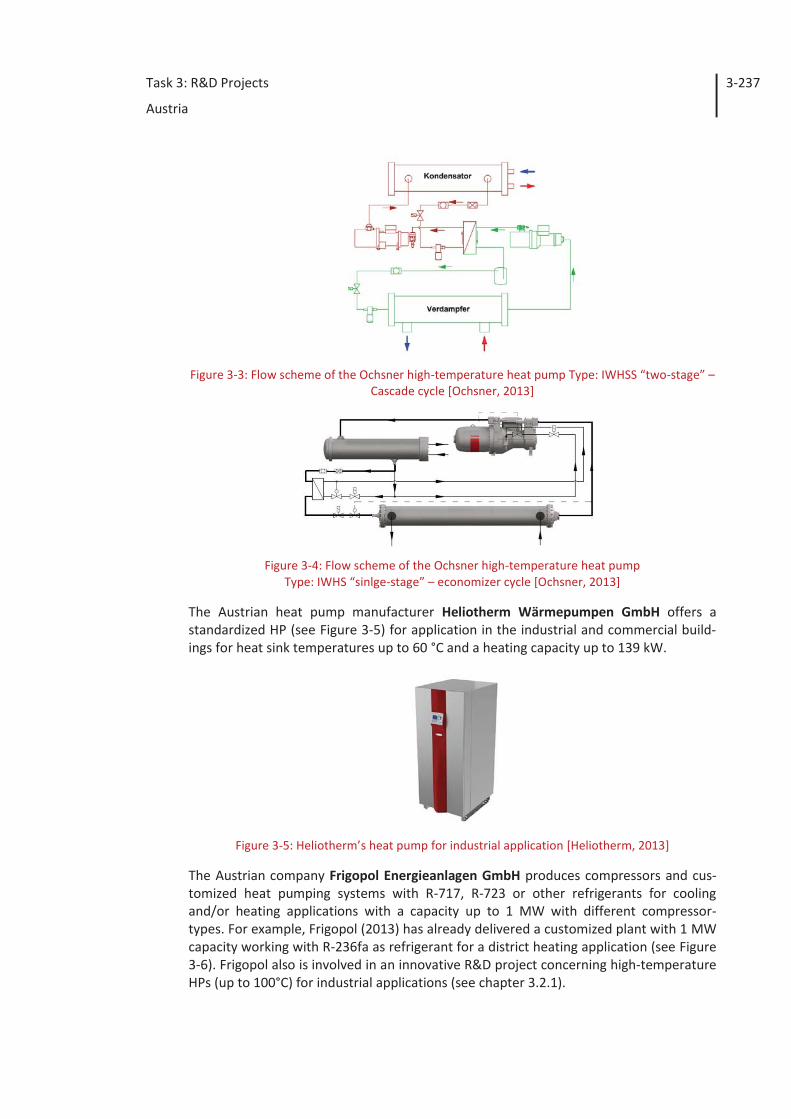
For various applications in commercial buildings or in the industry the heat pump manu-facture OCHSNER GmbH offers a series of heat pumps with semi-hermetic compact screw compressors with a capacity from 100 to 960 kW. For heat sink temperature lev-els up to 65 °C Ochsner uses R-134a, R-407C or commercial refrigerants. Additionally Ochsner also offers heat pumps for industrial applications, as e.g. the “Toppump”. For high-temperature applications Ochsner offers standard industrial heat pumps, which can lift waste heat from a (external) temperature level of 40 up to 98 °C at a low tempera-ture difference of the heat sink (5 to 10 K). As refrigerant the so called “Öko1” (by Ochsner), which is nonflammable and nontoxic, offers appropriate pressure levels at this high temperature levels. [Ochsner, 2013]
Figure 3-2: High-temperature heat pump [Ochsner, 2013]
According to the available waste heat temperature level Ochsner has two kind of this high-temperature heat pump in their portfolio, both a so called “two-stage” HP (IHWSS, see Figure 3-3) for heat source temperatures above 10°C, which is basically a cascade plant, and a “single-stage” HP (IHWS, see Figure 3-4) for heat source temperatures from 35 to 55 °C, which is designed as economizer cycle.
Task 3: R&D Projects
Austria
3-237
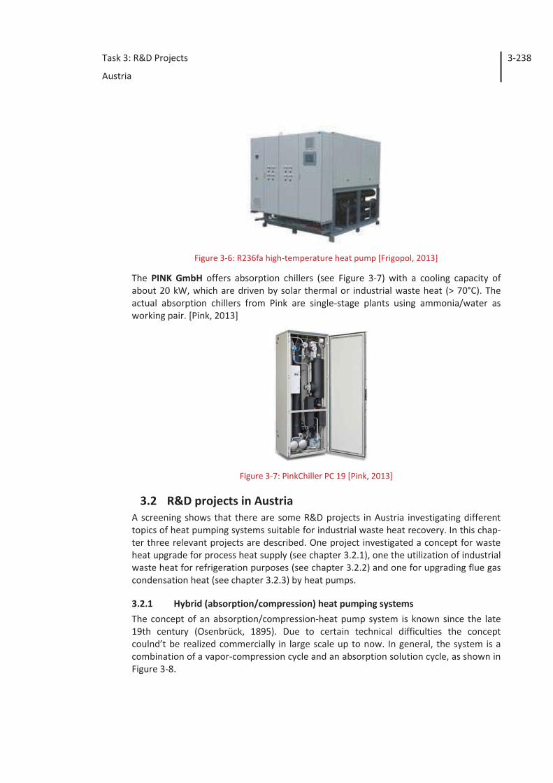
Figure 3-3: Flow scheme of the Ochsner high-temperature heat pump Type: IWHSS “two-stage” – Cascade cycle [Ochsner, 2013]
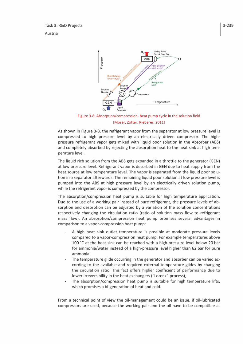
Figure 3-4: Flow scheme of the Ochsner high-temperature heat pump
Type: IWHS “sinlge-stage” – economizer cycle [Ochsner, 2013]
The Austrian heat pump manufacturer Heliotherm Wärmepumpen GmbH offers a standardized HP (see Figure 3-5) for application in the industrial and commercial build-ings for heat sink temperatures up to 60 °C and a heating capacity up to 139 kW.
Figure 3-5: Heliotherm’s heat pump for industrial application [Heliotherm, 2013]
The Austrian company Frigopol Energieanlagen GmbH produces compressors and cus-tomized heat pumping systems with R-717, R-723 or other refrigerants for cooling and/or heating applications with a capacity up to 1 MW with different compressor-types. For example, Frigopol (2013) has already delivered a customized plant with 1 MW capacity working with R-236fa as refrigerant for a district heating application (see Figure 3-6). Frigopol also is involved in an innovative R&D project concerning high-temperature HPs (up to 100°C) for industrial applications (see chapter 3.2.1).
Task 3: R&D Projects
Austria
3-238
Figure 3-6: R236fa high-temperature heat pump [Frigopol, 2013]
The PINK GmbH offers absorption chillers (see Figure 3-7) with a cooling capacity of about 20 kW, which are driven by solar thermal or industrial waste heat (> 70°C). The actual absorption chillers from Pink are single-stage plants using ammonia/water as working pair. [Pink, 2013]
Figure 3-7: PinkChiller PC 19 [Pink, 2013]
3.2 R&D projects in Austria A screening shows that there are some R&D projects in Austria investigating different topics of heat pumping systems suitable for industrial waste heat recovery. In this chap-ter three relevant projects are described. One project investigated a concept for waste heat upgrade for process heat supply (see chapter 3.2.1), one the utilization of industrial waste heat for refrigeration purposes (see chapter 3.2.2) and one for upgrading flue gas condensation heat (see chapter 3.2.3) by heat pumps.
3.2.1 Hybrid (absorption/compression) heat pumping systems The concept of an absorption/compression-heat pump system is known since the late 19th century (Osenbrück, 1895). Due to certain technical difficulties the concept coulnd’t be realized commercially in large scale up to now. In general, the system is a combination of a vapor-compression cycle and an absorption solution cycle, as shown in Figure 3-8.
Task 3: R&D Projects
Austria
3-239
Figure 3-8: Absorption/compression- heat pump cycle in the solution field
[Moser, Zotter, Rieberer, 2011]
As shown in Figure 3-8, the refrigerant vapor from the separator at low pressure level is compressed to high pressure level by an electrically driven compressor. The high-pressure refrigerant vapor gets mixed with liquid poor solution in the Absorber (ABS) and completely absorbed by rejecting the absorption heat to the heat sink at high tem-perature level.
The liquid rich solution from the ABS gets expanded in a throttle to the generator (GEN) at low pressure level. Refrigerant vapor is desorbed in GEN due to heat supply from the heat source at low temperature level. The vapor is separated from the liquid poor solu-tion in a separator afterwards. The remaining liquid poor solution at low pressure level is pumped into the ABS at high pressure level by an electrically driven solution pump, while the refrigerant vapor is compressed by the compressor.
The absorption/compression heat pump is suitable for high temperature application. Due to the use of a working pair instead of pure refrigerant, the pressure levels of ab-sorption and desorption can be adjusted by a variation of the solution concentrations respectively changing the circulation ratio (ratio of solution mass flow to refrigerant mass flow). An absorption/compression heat pump promises several advantages in comparison to a vapor-compression heat pump:
- A high heat sink outlet temperature is possible at moderate pressure levels compared to a vapor-compression heat pump. For example temperatures above 100 °C at the heat sink can be reached with a high-pressure level below 20 bar for ammonia/water instead of a high-pressure level higher than 62 bar for pure ammonia.
- The temperature glide occurring in the generator and absorber can be varied ac-cording to the available and required external temperature glides by changing the circulation ratio. This fact offers higher coefficient of performance due to lower irreversibility in the heat exchangers (“Lorenz”-process),
- The absorption/compression heat pump is suitable for high temperature lifts, which promises a bi-generation of heat and cold.
From a technical point of view the oil-management could be an issue, if oil-lubricated compressors are used, because the working pair and the oil have to be compatible at
Task 3: R&D Projects
Austria
3-240
high temperatures and arrangements for the oil return have to be considered, which are more complex than in vapor-compression heat pumps. The use of a conventional oil-lubricated compressor is limited due to high discharge temperatures and the thermal stability of the oil. At very high pressure ratios multi-stage compression has to be taken into account for higher coefficients of performance. Finally, a higher complexity of the control system results from a more complex system design.
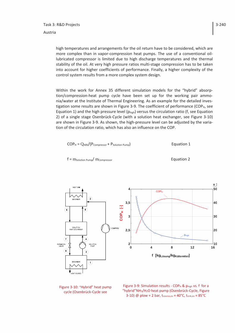
Within the work for Annex 35 different simulation models for the “hybrid” absorp-tion/compression-heat pump cycle have been set up for the working pair ammo-nia/water at the Institute of Thermal Engineering. As an example for the detailed inves-tigation some results are shown in Figure 3-9. The coefficient of performance (COPH, see Equation 1) and the high pressure level (phigh) versus the circulation ratio (f, see Equation 2) of a single stage Osenbrück-Cycle (with a solution heat exchanger, see Figure 3-10) are shown in Figure 3-9. As shown, the high-pressure level can be adjusted by the varia-tion of the circulation ratio, which has also an influence on the COP.
COPH = QABS/(PCompressor + PSolution Pump) Equation 1
f = mSolution Pump/ mCompressor Equation 2
Figure 3-9: Simulation results - COPH & phigh vs. f for a “hybrid”NH3/H2O heat pump (Osenbrück-Cycle, Figure
3-10) @ plow = 2 bar, tsource,ex = 40°C, tsink,ex = 85°C
Figure 3-10: “Hybrid” heat pump cycle (Osenbrück-Cycle see
0 4 8 12 16
x 1
2
2,5
3
3,5
4
10
20
30
40
50
f [kgLösung/kgKältemittel]
CO
P H [
-]
COPH
phigh
Task 3: R&D Projects
Austria
3-241
Nordtvedt, 2005) [Vehovec et al., 2013]
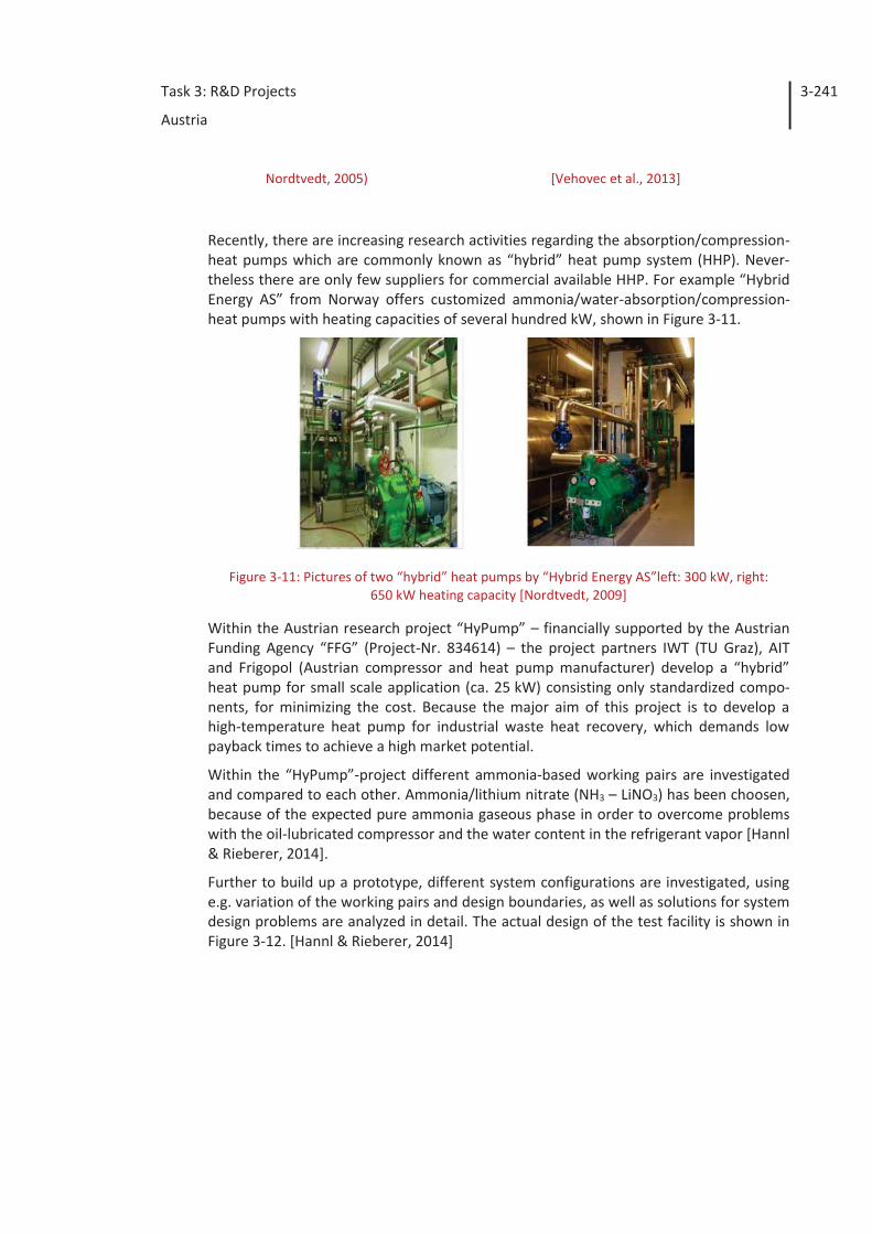
Recently, there are increasing research activities regarding the absorption/compression-heat pumps which are commonly known as “hybrid” heat pump system (HHP). Never-theless there are only few suppliers for commercial available HHP. For example “Hybrid Energy AS” from Norway offers customized ammonia/water-absorption/compression-heat pumps with heating capacities of several hundred kW, shown in Figure 3-11.
Figure 3-11: Pictures of two “hybrid” heat pumps by “Hybrid Energy AS”left: 300 kW, right: 650 kW heating capacity [Nordtvedt, 2009]
Within the Austrian research project “HyPump” – financially supported by the Austrian Funding Agency “FFG” (Project-Nr. 834614) – the project partners IWT (TU Graz), AIT and Frigopol (Austrian compressor and heat pump manufacturer) develop a “hybrid” heat pump for small scale application (ca. 25 kW) consisting only standardized compo-nents, for minimizing the cost. Because the major aim of this project is to develop a high-temperature heat pump for industrial waste heat recovery, which demands low payback times to achieve a high market potential.
Within the “HyPump”-project different ammonia-based working pairs are investigated and compared to each other. Ammonia/lithium nitrate (NH3 – LiNO3) has been choosen, because of the expected pure ammonia gaseous phase in order to overcome problems with the oil-lubricated compressor and the water content in the refrigerant vapor [Hannl & Rieberer, 2014].
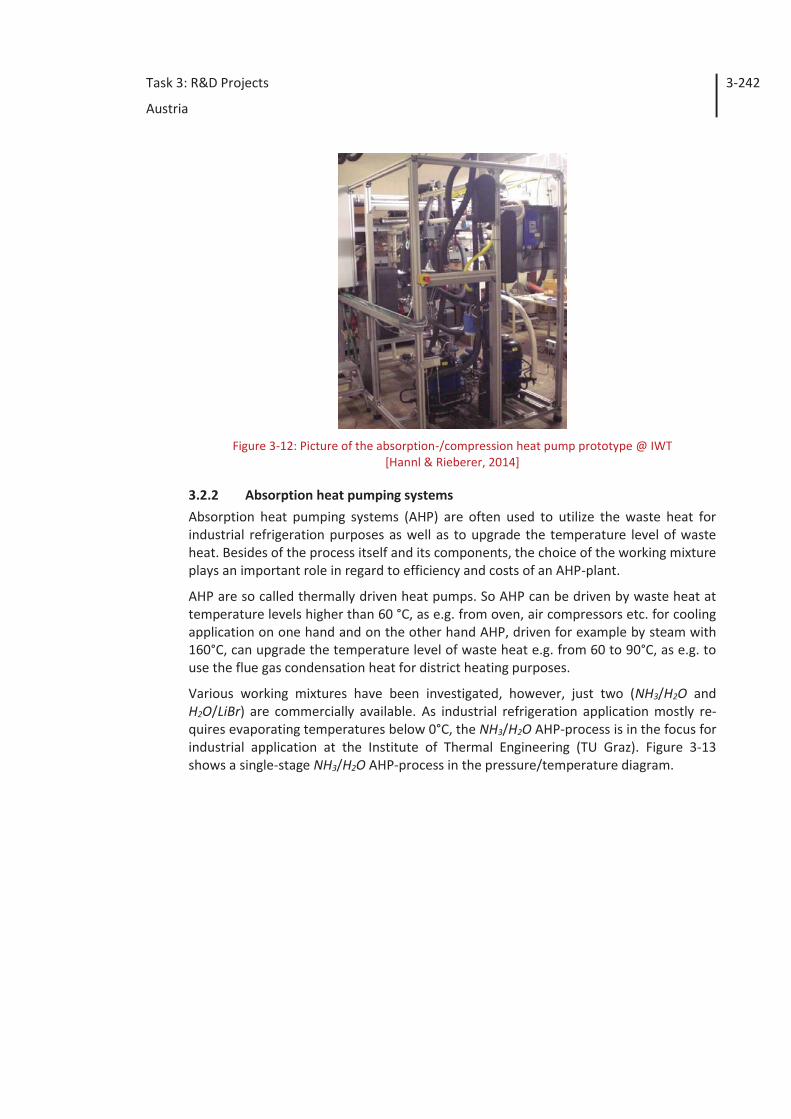
Further to build up a prototype, different system configurations are investigated, using e.g. variation of the working pairs and design boundaries, as well as solutions for system design problems are analyzed in detail. The actual design of the test facility is shown in Figure 3-12. [Hannl & Rieberer, 2014]
Task 3: R&D Projects
Austria
3-242
Figure 3-12: Picture of the absorption-/compression heat pump prototype @ IWT
[Hannl & Rieberer, 2014]
3.2.2 Absorption heat pumping systems Absorption heat pumping systems (AHP) are often used to utilize the waste heat for industrial refrigeration purposes as well as to upgrade the temperature level of waste heat. Besides of the process itself and its components, the choice of the working mixture plays an important role in regard to efficiency and costs of an AHP-plant.
AHP are so called thermally driven heat pumps. So AHP can be driven by waste heat at temperature levels higher than 60 °C, as e.g. from oven, air compressors etc. for cooling application on one hand and on the other hand AHP, driven for example by steam with 160°C, can upgrade the temperature level of waste heat e.g. from 60 to 90°C, as e.g. to use the flue gas condensation heat for district heating purposes.
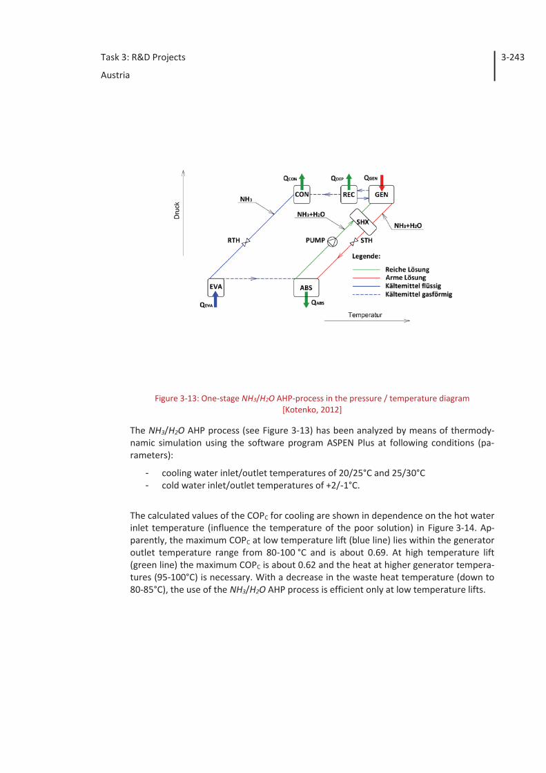
Various working mixtures have been investigated, however, just two (NH3/H2O and H2O/LiBr) are commercially available. As industrial refrigeration application mostly re-quires evaporating temperatures below 0°C, the NH3/H2O AHP-process is in the focus for industrial application at the Institute of Thermal Engineering (TU Graz). Figure 3-13 shows a single-stage NH3/H2O AHP-process in the pressure/temperature diagram.
Task 3: R&D Projects
Austria
3-243
Figure 3-13: One-stage NH3/H2O AHP-process in the pressure / temperature diagram [Kotenko, 2012]
The NH3/H2O AHP process (see Figure 3-13) has been analyzed by means of thermody-namic simulation using the software program ASPEN Plus at following conditions (pa-rameters):
- cooling water inlet/outlet temperatures of 20/25°C and 25/30°C - cold water inlet/outlet temperatures of +2/-1°C.
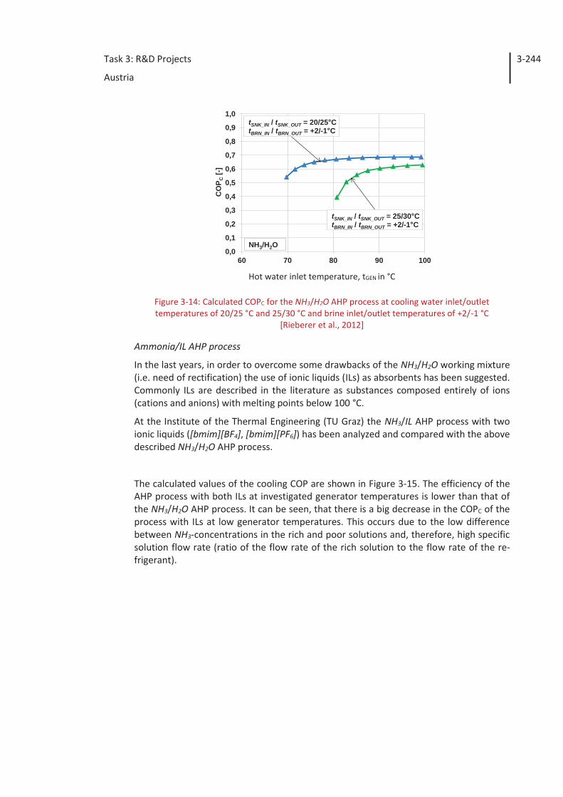
The calculated values of the COPC for cooling are shown in dependence on the hot water inlet temperature (influence the temperature of the poor solution) in Figure 3-14. Ap-parently, the maximum COPC at low temperature lift (blue line) lies within the generator outlet temperature range from 80-100 °C and is about 0.69. At high temperature lift (green line) the maximum COPC is about 0.62 and the heat at higher generator tempera-tures (95-100°C) is necessary. With a decrease in the waste heat temperature (down to 80-85°C), the use of the NH3/H2O AHP process is efficient only at low temperature lifts.
Task 3: R&D Projects
Austria
3-244
Hot water inlet temperature, tGEN in °C
Figure 3-14: Calculated COPC for the NH3/H2O AHP process at cooling water inlet/outlet temperatures of 20/25 °C and 25/30 °C and brine inlet/outlet temperatures of +2/-1 °C
[Rieberer et al., 2012]
Ammonia/IL AHP process
In the last years, in order to overcome some drawbacks of the NH3/H2O working mixture (i.e. need of rectification) the use of ionic liquids (ILs) as absorbents has been suggested. Commonly ILs are described in the literature as substances composed entirely of ions (cations and anions) with melting points below 100 °C.
At the Institute of the Thermal Engineering (TU Graz) the NH3/IL AHP process with two ionic liquids ([bmim][BF4], [bmim][PF6]) has been analyzed and compared with the above described NH3/H2O AHP process.
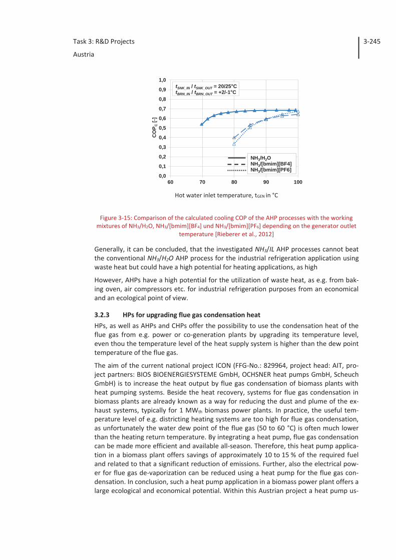
The calculated values of the cooling COP are shown in Figure 3-15. The efficiency of the AHP process with both ILs at investigated generator temperatures is lower than that of the NH3/H2O AHP process. It can be seen, that there is a big decrease in the COPC of the process with ILs at low generator temperatures. This occurs due to the low difference between NH3-concentrations in the rich and poor solutions and, therefore, high specific solution flow rate (ratio of the flow rate of the rich solution to the flow rate of the re-frigerant).
0,0
0,1
0,2
0,3
0,4
0,5
0,6
0,7
0,8
0,9
1,0
60 70 80 90 100
CO
P C[-]
NH3/H2O
tSNK_IN / tSNK_OUT = 20/25°CtBRN_IN / tBRN_OUT = +2/-1°C
tSNK_IN / tSNK_OUT = 25/30°CtBRN_IN / tBRN_OUT = +2/-1°C
Task 3: R&D Projects
Austria
3-245
Hot water inlet temperature, tGEN in °C
Figure 3-15: Comparison of the calculated cooling COP of the AHP processes with the working mixtures of NH3/H2O, NH3/[bmim][BF4] und NH3/[bmim][PF6] depending on the generator outlet
temperature [Rieberer et al., 2012]
Generally, it can be concluded, that the investigated NH3/IL AHP processes cannot beat the conventional NH3/H2O AHP process for the industrial refrigeration application using waste heat but could have a high potential for heating applications, as high
However, AHPs have a high potential for the utilization of waste heat, as e.g. from bak-ing oven, air compressors etc. for industrial refrigeration purposes from an economical and an ecological point of view.
3.2.3 HPs for upgrading flue gas condensation heat HPs, as well as AHPs and CHPs offer the possibility to use the condensation heat of the flue gas from e.g. power or co-generation plants by upgrading its temperature level, even thou the temperature level of the heat supply system is higher than the dew point temperature of the flue gas.
The aim of the current national project ICON (FFG-No.: 829964, project head: AIT, pro-ject partners: BIOS BIOENERGIESYSTEME GmbH, OCHSNER heat pumps GmbH, Scheuch GmbH) is to increase the heat output by flue gas condensation of biomass plants with heat pumping systems. Beside the heat recovery, systems for flue gas condensation in biomass plants are already known as a way for reducing the dust and plume of the ex-haust systems, typically for 1 MWth biomass power plants. In practice, the useful tem-perature level of e.g. districting heating systems are too high for flue gas condensation, as unfortunately the water dew point of the flue gas (50 to 60 °C) is often much lower than the heating return temperature. By integrating a heat pump, flue gas condensation can be made more efficient and available all-season. Therefore, this heat pump applica-tion in a biomass plant offers savings of approximately 10 to 15 % of the required fuel and related to that a significant reduction of emissions. Further, also the electrical pow-er for flue gas de-vaporization can be reduced using a heat pump for the flue gas con-densation. In conclusion, such a heat pump application in a biomass power plant offers a large ecological and economical potential. Within this Austrian project a heat pump us-
0,0
0,1
0,2
0,3
0,4
0,5
0,6
0,7
0,8
0,9
1,0
60 70 80 90 100
CO
P C[-]
NH3/H2O NH3/[bmim][BF4]NH3/[bmim][PF6]
tSNK_IN / tSNK_OUT = 20/25°CtBRN_IN / tBRN_OUT = +2/-1°C
Task 3: R&D Projects
Austria
3-246
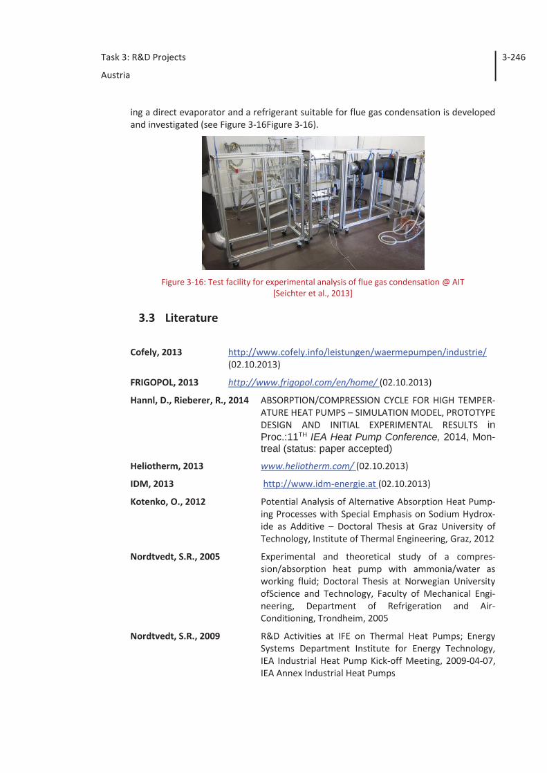
ing a direct evaporator and a refrigerant suitable for flue gas condensation is developed and investigated (see Figure 3-16Figure 3-16).
Figure 3-16: Test facility for experimental analysis of flue gas condensation @ AIT
[Seichter et al., 2013]
3.3 Literature
Cofely, 2013 http://www.cofely.info/leistungen/waermepumpen/industrie/ (02.10.2013)
FRIGOPOL, 2013 http://www.frigopol.com/en/home/ (02.10.2013)
Hannl, D., Rieberer, R., 2014 ABSORPTION/COMPRESSION CYCLE FOR HIGH TEMPER-ATURE HEAT PUMPS – SIMULATION MODEL, PROTOTYPE DESIGN AND INITIAL EXPERIMENTAL RESULTS in Proc.:11TH IEA Heat Pump Conference, 2014, Mon-treal (status: paper accepted)
Heliotherm, 2013 www.heliotherm.com/ (02.10.2013)
IDM, 2013 http://www.idm-energie.at (02.10.2013)
Kotenko, O., 2012 Potential Analysis of Alternative Absorption Heat Pump-ing Processes with Special Emphasis on Sodium Hydrox-ide as Additive – Doctoral Thesis at Graz University of Technology, Institute of Thermal Engineering, Graz, 2012
Nordtvedt, S.R., 2005 Experimental and theoretical study of a compres-sion/absorption heat pump with ammonia/water as working fluid; Doctoral Thesis at Norwegian University ofScience and Technology, Faculty of Mechanical Engi-neering, Department of Refrigeration and Air-Conditioning, Trondheim, 2005
Nordtvedt, S.R., 2009 R&D Activities at IFE on Thermal Heat Pumps; Energy Systems Department Institute for Energy Technology, IEA Industrial Heat Pump Kick-off Meeting, 2009-04-07, IEA Annex Industrial Heat Pumps
Task 3: R&D Projects
Austria
3-247
Moser, H., Zotter, G., Rieberer, R., 2011 „HyPump“- Hocheffiziente Hybrid-Wärmepumpe zur Wärmerückgewinnung in der Industrie - research pro-posal for the R&D project HyPump for KliEn – EE 2020 (5th call) processed by the Austrian Funding Agency “FFG” (Project-Nr. 834614) – Institute of Thermal Engi-neering at Graz University of Technology, Austrian Insti-tute of Technology and Frigopol, Graz 2011 (un-published)
Ochsner, 2013 Hochtemperatur-Industriewärmepumpe (Ciepiely T.) im Kolloquium: Großwärmepumpen & Hochtemperatur-Wärmepumpen – Energieeffizienz in ihrer stärksten Form, Frankfurt, am 16.04.2013
Osenbrück, A., 1895 Verfahren zur Kälteerzeugung bei Absorptionsmachinen, in Kaiserliches Patentamt. 1895: Germany
Pink, W., 2013 www.pink.co.at/ (02.10.2013)
Rieberer, R., Kotenko, O., Moser, H., Zotter, G., 2012 Realisierungspotential von Absorptionswärmepumpen mit ionischen Flüssigkeiten – published research report of the R&D project “IonA” (FFG Nr.: 825477 – 3. Call NE 2020, KliEn) – Institute of Thermal Engineering at Graz University of Technology, Wien, 2012
Seichter S., Fleckl T., Reichl C., 2013 "Development of a wind tunnel to investigate heat and mass transfer to heat exchangers"; Vortrag: Gemeinsa-me Jahrestagung der Österreichischen und Schweizer Physikalischen Gesellschaft, Linz; 03.09.2013 - 06.09.2013.
Vehovec, V., Zotter, G., Rieberer, R., Mauthner, F., Brunner, C., 2013 Industrielle Forschung für PROMISE DEMO (Produzieren mit Solarer Energie – Demonstrationsprojekt), Assmann Ladenbau, Institut für Wärmetechnik der TU Graz, AEE Intec; Hrsg: Der Klima- und Energiefonds der Bundesre-gierung (FFG-Nr.: 825537), Vienna, 2013
Task 3: R&D Projects
Canada
4-248
4 Canada
4.1 Introduction
Canadian industry requires about 48 % of the total country primary energy input. The annual energy used by eight major manufacturing industries, such as pulp and paper, primary metals and oil, accounts for about 1.7 million TJ representing 65 % of the total energy used by all Canadian industries [NEB, 2008]. But, up to 71 % of the energy input is released to the environment via waste heat streams such as stack emissions (combus-tion gases and hot air), steam, process gases and liquid effluents. The largest heat losses occur in the pulp and paper industry (36.4%) followed by primary metal manufacturing industries (23 %) [Stricker, 2006].
IEA-IETS Annex 13 / IEA-HPP Annex 35 [Annex 35, 2010] defines industrial heat pumps (IHP) as medium and high thermal power units used for heat recovery and heat upgrad-ing in industrial processes. It also specifies that … heat pump in medium … power ranges …can be used not only for heat recovery in industrial processes, but also for heating and air-conditioning of industrial buildings.
Since industrial heat pumps can significantly reduce fossil fuel consumption and, thus, contribute to global energy conservation and industrial productivity improvement, as well as to reducing greenhouse gas emissions, Canada has initiated a number of R&D studies followed by some field demonstration projects. The scope was to indentify ap-propriate heat pumps applications for meeting future industry and environmental re-quirements.
Canada’s R&D projects have been conducted in a specific national energetic context where prices of primary energies (electricity, natural gas, oil) are relatively low and where industrial companies are investing to improve production efficiency (profitability) rather than reducing their specific energy consumption.
In spite of this particular energetic environment, theoretical and experimental R&D work has been performed in order to improve the heat pump vapour compression cycles, particularly by using ejectors [Scott].
Moreover, because industrial waste heat in liquid form available at low-temperatures represents about 25 % of the total energy used by Canadian manufacturing industry, a number of R&D work has focused on high-temperature heat pumps able to recover heat at relatively low temperatures, generally between -5°C and 35 °C, and produce hot wa-ter at temperatures up to 85-90 °C [Minea, 2010]. In this area, the Canadian R&D pro-jects have focused on using natural refrigerants such as carbon dioxide and ammonia, and more or less known thermodynamic cycles, as well as on developing national exper-tise and improving public and industry awareness.
Task 3: R&D Projects
Canada
4-249
4.2 Historical background
In the past, the IEA HPP Annex 9 project (High Temperature Industrial Heat Pumps - 1990) presented a status report on high-temperature industrial heat pumps, as well as a detailed description of R&D efforts going on at the time [Annex 9, 1990].
Later, the IEA HPP Annex 21 (Global Environmental Benefits of Industrial Heat Pumps -1996) provided an overview of potential industrial heat pump applications [Annex 21, 1995], and identified the lack of operator and engineer experience as the main market barrier for industrial heat pumps. Other reasons that have contributed to a low level of industrial heat pump utilization were the relatively low cost of primary energies and a lack of knowledge on the potential benefits.
Prior to 1995, low-temperature industrial heat pumps were developed and implement-ed in Canada, especially in lumber drying and evaporation/distillation processes, and also in the food industry, including dairies, poultry, sugar refining, breweries, liquor pro-duction and fish processing [Annex 21, 1995].
Toward the end of 1993, 17 % of 14 chosen processes involving more than 1,900 indi-vidual plants were using industrial heat pumps, more than 90 % of which were in lumber drying. At the end of 2010, in 339 plants surveyed in Québec (Eastern Canada), Ontario and Manitoba (Central Canada) and British Columbia (Western Canada), 31 % of existing industrial heat pumps (26) were used for drying, 27 % for waste heat recovery and 8 % for evaporation processes with cooling capacities varying between 14 and 1,050 kW [Minea, 2010].
Today, in spite of their well known potential benefits (e.g. reduced energy consumption for heating, increased capacity of existing processes, and improved product quality and plant environmental performance), the number of industrial heat pumps (IHPs) installed in Canada is still relatively low compared to the number of existing technically and eco-nomically viable opportunities. Higher capital costs and low energy prices, as well as a lack of knowledge on the potential benefits and/or experience with industrial heat pump technology may explain this situation.
4.3 Canada’s R&D projects
According to the definition of IHPs set forth in the Annex 35/13 legal text [Annex 35, 2010], over the last decade, Canada’s R&D projects have focused on recovering low-grade waste heat from relatively small- to medium-scale industrial manufacturing facili-ties in order to supply heat for building domestic hot water consumption and/or indus-trial heating purposes. The objective was to properly design, integrate and operate sev-eral types of IHPs in various energy intensive industrial processes able to provide suffi-cient amounts of waste heat at appropriate quality levels, flow rates and temperatures.
During the last few years, two Canadian public research institutions, i.e. CANMET Energy Technology Centre (CETC) - Varennes [Scott] and Hydro-Québec Research Institute - Laboratoire des technologies de l’énergie (LTE) [Minea, 2010] have conducted a number of R&D projects on industrial heat pumps. All these projects were intended to respond
Task 3: R&D Projects
Canada
4-250
to future requirements, such as a reduction of the energetic intensity of small- and me-dium-sized industrial processes and of environmental thermal pollution.
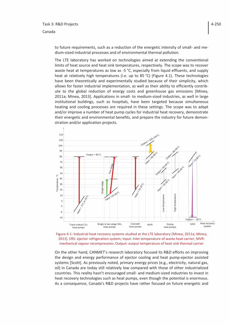
The LTE laboratory has worked on technologies aimed at extending the conventional limits of heat source and heat sink temperatures, respectively. The scope was to recover waste heat at temperatures as low as -5 °C, especially from liquid effluents, and supply heat at relatively high temperatures (i.e. up to 85 °C) (Figure 4.1). These technologies have been theoretically and experimentally studied because of their simplicity, which allows for faster industrial implementation, as well as their ability to efficiently contrib-ute to the global reduction of energy costs and greenhouse gas emissions [Minea, 2011a; Minea, 2013]. Applications in small- to medium-sized industries, as well in large institutional buildings, such as hospitals, have been targeted because simultaneous heating and cooling processes are required in these settings. The scope was to adapt and/or improve a number of heat pump cycles for industrial heat recovery, demonstrate their energetic and environmental benefits, and prepare the industry for future demon-stration and/or application projects.
Figure 4-1: Industrial heat recovery systems studied at the LTE laboratory [Minea, 2011a; Minea,
2013]. ERS: ejector refrigeration system; Input: inlet temperature of waste heat carrier; MVR: mechanical vapour recompression; Output: output temperature of heat sink thermal carrier
On the other hand, CANMET’s research laboratory focused its R&D efforts on improving the design and energy performance of ejector cooling and heat pump-ejector assisted systems [Scott]. As previously noted, primary energy prices (e.g., electricity, natural gas, oil) in Canada are today still relatively low compared with those of other industrialized countries. This reality hasn’t encouraged small- and medium-sized industries to invest in heat recovery technologies such as heat pumps, even though the potential is enormous. As a consequence, Canada’s R&D projects have rather focused on future energetic and
Single & two-stage NH3heat pumps
Trans-critical CO2heat pumps
Cascadeheat pumps
15
25
35
45
55
65
75
85
95
5
0
Tem
pera
ture
,°C
Input =10-30°C
Inpu
t =-5
°Cto
15°C In
put =
15-3
5°C
Heat recoverysystem
-5
Two-
stag
e
Output = 85°C
Sin
gle-
stag
e
100
-10
MVR ERS
105
110
Input
= 75-90
°C
Output ~ -10°C
Output = 100-105°C
Input
= 80-95
°C
Dryingheat pumps
Low
-tem
pera
ture
Hig
h-te
mpe
ratu
re
Input
= 35-45
°C
Output
= 55-65
°C
Input
= 55-65
°C
Output
= 85-95
°C
Task 3: R&D Projects
Canada
4-251
climate crises by proposing efficient and reliable technical solutions to use the enormous quantities of low-grade industrial waste heat available.
4.3.1 Thermally-driven ejector heat pumps
The use of ejectors as vapor compression devices in thermally driven heat pump systems has received increased attention over the past two decades [Scott]. Unlike mechanical vapour compression heat pumps, such systems are driven by heat instead of electricity.
Ejectors are simple devices, generally used to compress a vapour stream and produce vacuum simultaneously. They have no moving parts, are relatively easy to manufacture, represent relatively inexpensive alternatives to conventional mechanical vapour com-pressors, and have low maintenance costs. These features can give ejector heat pumps an advantage over other thermally driven systems with comparable COPs (e.g. absorp-tion, adsorption). However, the ejectors require primary motive steam at a relatively high pressure, mostly 7-15 bars, and their noise level can be rather high.
In traditional industrial ejector applications, water steam is used as a moving fluid to generate vacuum and cooling effects [Ashrae, 1969]. To improve the efficiency of the simple ejector cycle, more complex cycles have been investigated [Yu, 2006], as well as the integration of ejectors in vapour compression and absorption systems. Significant efforts have also been devoted to the development of solar driven ejector refrigeration systems [Pridasawas, 2008].
More recently, new research work has shown the benefits of using other moving fluids to provide more favorable operating conditions and increase system efficiency. Several HFCs (e.g. R-245fa, R-141b, R-134a and R-142b) as well as natural refrigerants (e.g. bu-tane, propane and CO2) [Elbel, 2011] have been considered as alternative working fluids.
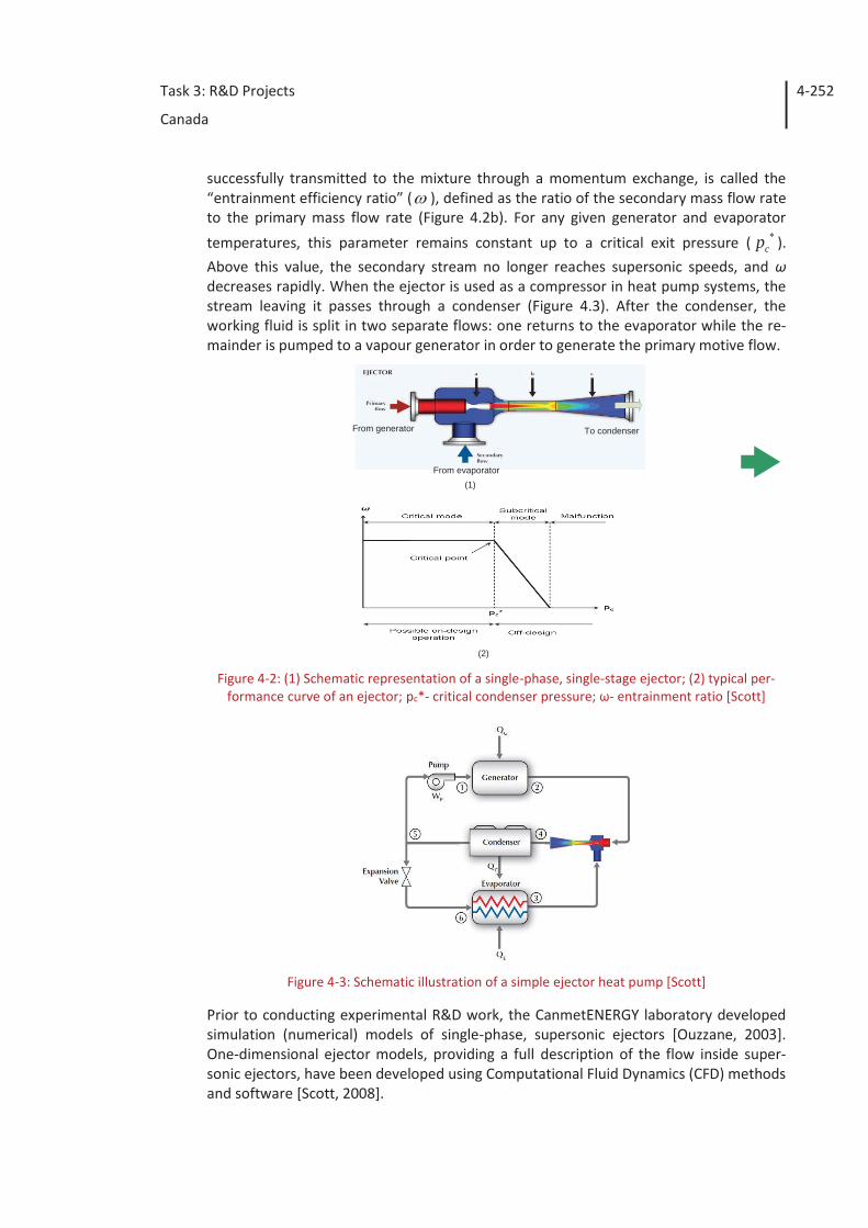
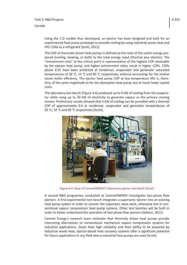
A typical ejector has one inlet to admit the motive (primary) fluid (flow) and another one to admit the gas/vapour mixture to be discharged from the evaporator (Figure 4.2a) [Scott]. At the nozzle exit area, the primary stream flows at supersonic speeds at low pressure and temperature levels. This induces the secondary flow from the evaporator to pass through a converging section, resulting in the secondary stream attaining sonic flow conditions. In the constant area section (b), the supersonic primary stream and the secondary stream mix. Friction, mixing losses and shock formation in this mixing section cause the streams to be compressed and decelerate to subsonic velocities. Further compression occurs in the diffuser, after which the mixed stream flows to the condenser (c) [Ouzzane, 2003; Scott, 2008].
Such single- or multiple-stage ejector systems are designed to convert the pressure en-ergy of the motive fluid to velocity energy in order to carry the suction fluid, and then to recompress the mixed fluid by converting velocity energy back into pressure energy. A properly designed nozzle will economically make use of high pressure fluids to compress them from a low pressure area to a higher pressure one.
Typically, ejector efficiency involves comparing energy output to energy input. Since ejectors approximate a theoretically isentropic process, their overall efficiency is ex-pressed as a function of entrainment efficiency. The direct entrainment of a low velocity suction fluid by a motive fluid, results in an unavoidable loss of kinetic energy owing to the impact and turbulence originally present in the motive fluid. This fraction, which is
Task 3: R&D Projects
Canada
4-252
successfully transmitted to the mixture through a momentum exchange, is called the “entrainment efficiency ratio” ( ), defined as the ratio of the secondary mass flow rate to the primary mass flow rate (Figure 4.2b). For any given generator and evaporator
temperatures, this parameter remains constant up to a critical exit pressure ( cp ). Above this value, the secondary stream no longer reaches supersonic speeds, and ω decreases rapidly. When the ejector is used as a compressor in heat pump systems, the stream leaving it passes through a condenser (Figure 4.3). After the condenser, the working fluid is split in two separate flows: one returns to the evaporator while the re-mainder is pumped to a vapour generator in order to generate the primary motive flow.
Figure 4-2: (1) Schematic representation of a single-phase, single-stage ejector; (2) typical per-
formance curve of an ejector; pc*- critical condenser pressure; ω- entrainment ratio [Scott]
Figure 4-3: Schematic illustration of a simple ejector heat pump [Scott]
Prior to conducting experimental R&D work, the CanmetENERGY laboratory developed simulation (numerical) models of single-phase, supersonic ejectors [Ouzzane, 2003]. One-dimensional ejector models, providing a full description of the flow inside super-sonic ejectors, have been developed using Computational Fluid Dynamics (CFD) methods and software [Scott, 2008].
(1)
(2)
To condenser
From evaporator
From generator
Task 3: R&D Projects
Canada
4-253
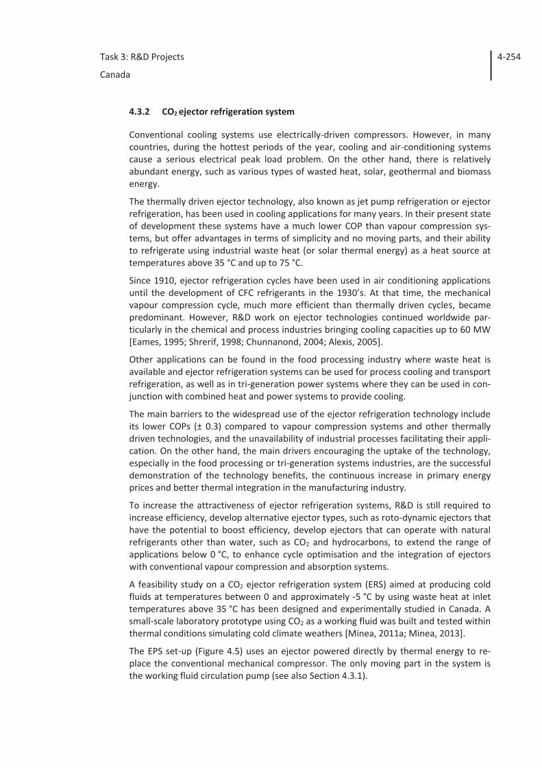
Using the 1-D models thus developed, an ejector has been designed and built for an experimental heat pump prototype to provide cooling by using industrial waste heat and HFC-134a as a refrigerant [Scott, 2011].
The COP of thermally driven heat pumps is defined as the ratio of the useful energy pro-duced (cooling, heating, or both) to the total energy input (thermal plus electric). The “entrainment ratio” at the critical point is representative of the highest COP attainable by the ejector heat pump, and higher entrainment ratios result in higher COPs. COPs above 0.35 have been predicted at condenser, evaporator and generator saturated temperatures of 36 °C, 15 °C and 80 °C respectively, without accounting for the motive steam boiler efficiency. The ejector heat pump COP at low temperature lifts is, there-fore, of the same magnitude as for the absorption heat pump, but at much lower capital costs.
The laboratory test bench (Figure 4.4) produced up to 9 kW of cooling from the evapora-tor while using up to 30 kW of electricity to generate vapour as the primary moving stream. Preliminary results showed that 5 kW of cooling can be provided with a thermal COP of approximately 0.4 at condenser, evaporator and generator temperatures of 25 °C, 10 °C and 90 °C respectively [Scott].
Figure 4-4: View of CanmetENERGY’s laboratory ejector test bench [Scott]
A second R&D programme conducted at CanmetENERGY investigates two-phase flow ejectors. A first experimental test bench integrates a supersonic ejector into an existing heat pump system in order to recover the expansion valve work, otherwise lost in con-ventional vapour compression heat pump systems. Other test benches will be built in order to better understand the operation of two-phase flow ejectors [Aidoun, 2011].
Canmet Energy’s research team estimates that thermally driven heat pumps provide interesting alternatives to conventional mechanical vapour compression systems for industrial applications. Given their high reliability and their ability to be powered by industrial waste heat, ejector-based heat recovery systems offer a significant potential for future applications in any field where industrial heat pumps are used [Scott].
Task 3: R&D Projects
Canada
4-254
4.3.2 CO2 ejector refrigeration system
Conventional cooling systems use electrically-driven compressors. However, in many countries, during the hottest periods of the year, cooling and air-conditioning systems cause a serious electrical peak load problem. On the other hand, there is relatively abundant energy, such as various types of wasted heat, solar, geothermal and biomass energy.
The thermally driven ejector technology, also known as jet pump refrigeration or ejector refrigeration, has been used in cooling applications for many years. In their present state of development these systems have a much lower COP than vapour compression sys-tems, but offer advantages in terms of simplicity and no moving parts, and their ability to refrigerate using industrial waste heat (or solar thermal energy) as a heat source at temperatures above 35 °C and up to 75 °C.
Since 1910, ejector refrigeration cycles have been used in air conditioning applications until the development of CFC refrigerants in the 1930’s. At that time, the mechanical vapour compression cycle, much more efficient than thermally driven cycles, became predominant. However, R&D work on ejector technologies continued worldwide par-ticularly in the chemical and process industries bringing cooling capacities up to 60 MW [Eames, 1995; Shrerif, 1998; Chunnanond, 2004; Alexis, 2005].
Other applications can be found in the food processing industry where waste heat is available and ejector refrigeration systems can be used for process cooling and transport refrigeration, as well as in tri-generation power systems where they can be used in con-junction with combined heat and power systems to provide cooling.
The main barriers to the widespread use of the ejector refrigeration technology include its lower COPs (± 0.3) compared to vapour compression systems and other thermally driven technologies, and the unavailability of industrial processes facilitating their appli-cation. On the other hand, the main drivers encouraging the uptake of the technology, especially in the food processing or tri-generation systems industries, are the successful demonstration of the technology benefits, the continuous increase in primary energy prices and better thermal integration in the manufacturing industry.
To increase the attractiveness of ejector refrigeration systems, R&D is still required to increase efficiency, develop alternative ejector types, such as roto-dynamic ejectors that have the potential to boost efficiency, develop ejectors that can operate with natural refrigerants other than water, such as CO2 and hydrocarbons, to extend the range of applications below 0 °C, to enhance cycle optimisation and the integration of ejectors with conventional vapour compression and absorption systems.
A feasibility study on a CO2 ejector refrigeration system (ERS) aimed at producing cold fluids at temperatures between 0 and approximately -5 °C by using waste heat at inlet temperatures above 35 °C has been designed and experimentally studied in Canada. A small-scale laboratory prototype using CO2 as a working fluid was built and tested within thermal conditions simulating cold climate weathers [Minea, 2011a; Minea, 2013].
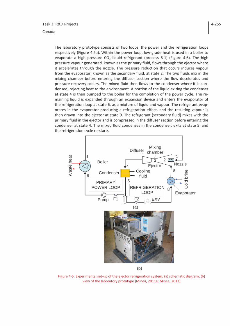
The EPS set-up (Figure 4.5) uses an ejector powered directly by thermal energy to re-place the conventional mechanical compressor. The only moving part in the system is the working fluid circulation pump (see also Section 4.3.1).
Task 3: R&D Projects
Canada
4-255
The laboratory prototype consists of two loops, the power and the refrigeration loops respectively (Figure 4.5a). Within the power loop, low-grade heat is used in a boiler to evaporate a high pressure CO2 liquid refrigerant (process 6-1) (Figure 4.6). The high pressure vapour generated, known as the primary fluid, flows through the ejector where it accelerates through the nozzle. The pressure reduction that occurs induces vapour from the evaporator, known as the secondary fluid, at state 2. The two fluids mix in the mixing chamber before entering the diffuser section where the flow decelerates and pressure recovery occurs. The mixed fluid then flows to the condenser where it is con-densed, rejecting heat to the environment. A portion of the liquid exiting the condenser at state 4 is then pumped to the boiler for the completion of the power cycle. The re-maining liquid is expanded through an expansion device and enters the evaporator of the refrigeration loop at state 6, as a mixture of liquid and vapour. The refrigerant evap-orates in the evaporator producing a refrigeration effect, and the resulting vapour is then drawn into the ejector at state 9. The refrigerant (secondary fluid) mixes with the primary fluid in the ejector and is compressed in the diffuser section before entering the condenser at state 4. The mixed fluid condenses in the condenser, exits at state 5, and the refrigeration cycle re-starts.
Figure 4-5: Experimental set-up of the ejector refrigeration system; (a) schematic diagram; (b)
view of the laboratory prototype [Minea, 2011a; Minea, 2013]
BoilerEjector
Evaporator
CondenserWas
tehe
at
Col
dbr
ine
Pump
Coolingfluid
EXVF1 F2
REFRIGERATIONLOOP
PRIMARYPOWER LOOP
123
4
56
7
8
9
1
(a)
(b)
Diffuser
Nozzle
Mixingchamber
Task 3: R&D Projects
Canada
4-256
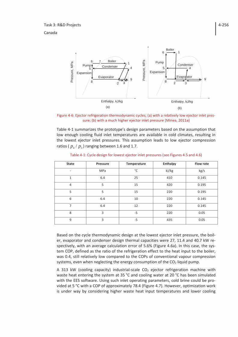
Figure 4-6: Ejector refrigeration thermodynamic cycles; (a) with a relatively low ejector inlet pres-
sure; (b) with a much higher ejector inlet pressure [Minea, 2011a]
Table 4-1 summarizes the prototype’s design parameters based on the assumption that low enough cooling fluid inlet temperatures are available in cold climates, resulting in the lowest ejector inlet pressures. This assumption leads to low ejector compression ratios ( 34 / pp ) ranging between 1.6 and 1.7.
Table 4-1: Cycle design for lowest ejector inlet pressures (see Figures 4.5 and 4.6)
State Pressure Temperature Enthalpy Flow rate
- MPa °C kJ/kg kg/s
1 6.4 25 410 0.145
4 5 15 420 0.195
5 5 15 220 0.195
6 6.4 10 220 0.145
7 6.4 12 220 0.145
8 3 -5 220 0.05
9 3 -5 435 0.05
Based on the cycle thermodynamic design at the lowest ejector inlet pressure, the boil-er, evaporator and condenser design thermal capacities were 27, 11.4 and 40.7 kW re-spectively, with an average calculation error of 5.6% (Figure 4.6a). In this case, the sys-tem COP, defined as the ratio of the refrigeration effect to the heat input to the boiler, was 0.4, still relatively low compared to the COPs of conventional vapour compression systems, even when neglecting the energy consumption of the CO2 liquid pump.
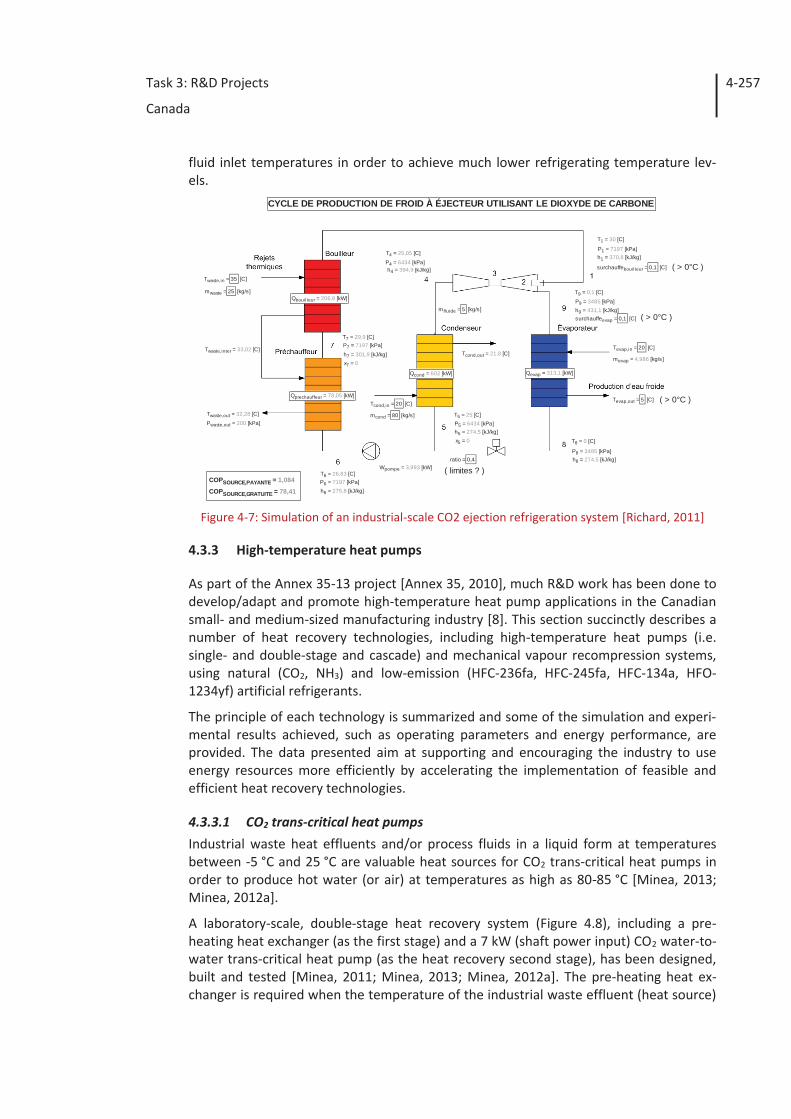
A 313 kW (cooling capacity) industrial-scale CO2 ejector refrigeration machine with waste heat entering the system at 35 °C and cooling water at 20 °C has been simulated with the EES software. Using such inlet operating parameters, cold brine could be pro-vided at 5 °C with a COP of approximately 78.4 (Figure 4.7). However, optimization work is under way by considering higher waste heat input temperatures and lower cooling
1
2 3
45
6 7
89P
ress
ure,
MP
a
Enthalpy, kJ/kg
Evaporator
Condenser
BoilerPump
Expansion
1
2 3
45
6
89P
ress
ure,
MP
a
Enthalpy, kJ/kg
Evaporator
Condenser
Boiler
Pump
Expansion
(a) (b)
Task 3: R&D Projects
Canada
4-257
fluid inlet temperatures in order to achieve much lower refrigerating temperature lev-els.
Figure 4-7: Simulation of an industrial-scale CO2 ejection refrigeration system [Richard, 2011]
4.3.3 High-temperature heat pumps
As part of the Annex 35-13 project [Annex 35, 2010], much R&D work has been done to develop/adapt and promote high-temperature heat pump applications in the Canadian small- and medium-sized manufacturing industry [8]. This section succinctly describes a number of heat recovery technologies, including high-temperature heat pumps (i.e. single- and double-stage and cascade) and mechanical vapour recompression systems, using natural (CO2, NH3) and low-emission (HFC-236fa, HFC-245fa, HFC-134a, HFO-1234yf) artificial refrigerants.
The principle of each technology is summarized and some of the simulation and experi-mental results achieved, such as operating parameters and energy performance, are provided. The data presented aim at supporting and encouraging the industry to use energy resources more efficiently by accelerating the implementation of feasible and efficient heat recovery technologies.
4.3.3.1 CO2 trans-critical heat pumps Industrial waste heat effluents and/or process fluids in a liquid form at temperatures between -5 °C and 25 °C are valuable heat sources for CO2 trans-critical heat pumps in order to produce hot water (or air) at temperatures as high as 80-85 °C [Minea, 2013; Minea, 2012a].
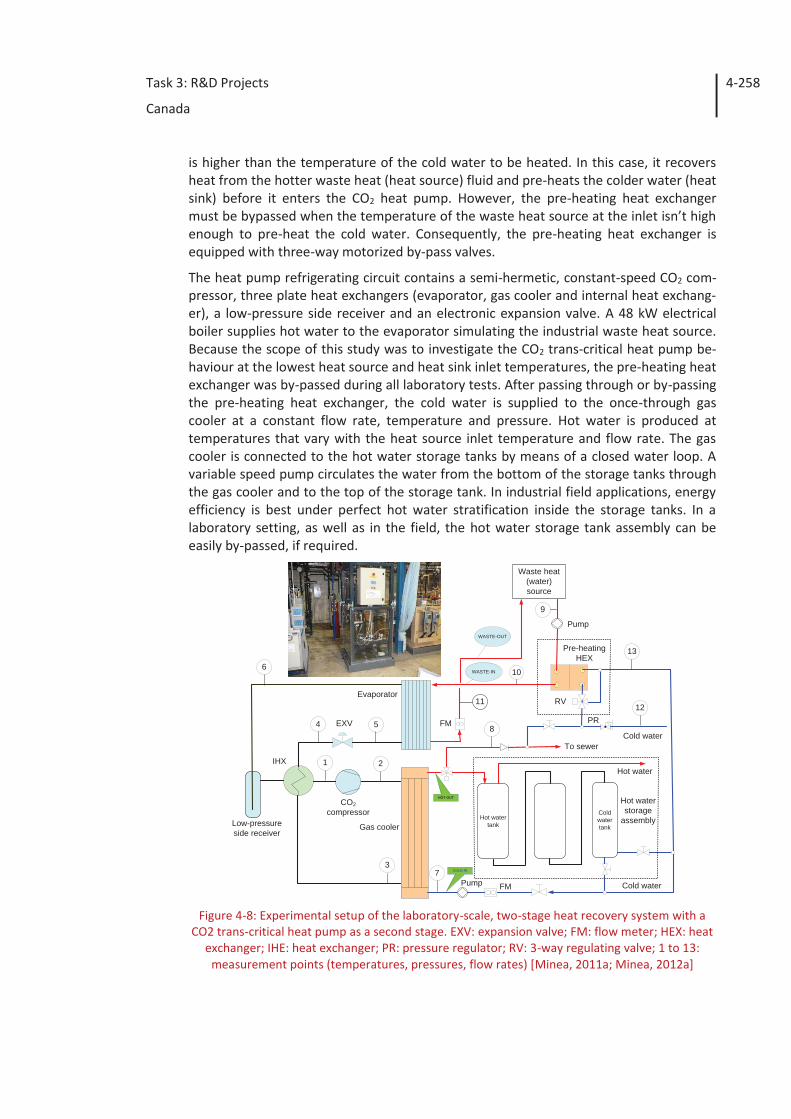
A laboratory-scale, double-stage heat recovery system (Figure 4.8), including a pre-heating heat exchanger (as the first stage) and a 7 kW (shaft power input) CO2 water-to-water trans-critical heat pump (as the heat recovery second stage), has been designed, built and tested [Minea, 2011; Minea, 2013; Minea, 2012a]. The pre-heating heat ex-changer is required when the temperature of the industrial waste effluent (heat source)
h1 = 370,8 [kJ/kg]
h4 = 394,9 [kJ/kg]
h5 = 274,5 [kJ/kg]
h6 = 275,8 [kJ/kg]
h7 = 301,9 [kJ/kg]
h8 = 274,5 [kJ/kg]
h9 = 431,1 [kJ/kg]
mcond = 80 [kg/s]
mevap = 4,986 [kg/s]
mfluide = 5 [kg/s]
mwaste = 25 [kg/s]
P1 = 7197 [kPa]
P4 = 6434 [kPa]
P5 = 6434 [kPa]
P6 = 7197 [kPa]
P7 = 7197 [kPa]
P8 = 3485 [kPa]
P9 = 3485 [kPa]
Pwaste,out = 200 [kPa]
Qbouilleur = 206,8 [kW]
Qcond = 602 [kW] Qevap = 313,1 [kW]
ratio = 0,4
surchauffebouilleur = 0,1 [C]
surchauffeevap = 0,1 [C]
x7 = 0
x5 = 0
Wpompe = 3,993 [kW]
Twaste,out = 32,28 [C]
Twaste,inter = 33,02 [C]
Twaste,in = 35 [C]
Tevap,out = 5 [C]
Tevap,in = 20 [C]Tcond,out = 21,8 [C]
Tcond,in = 20 [C]
T9 = 0,1 [C]
T8 = 0 [C]
T7 = 29,9 [C]
T6 = 26,83 [C]
T5 = 25 [C]
T4 = 25,05 [C]
T1 = 30 [C]
Qprechauffeur = 78,05 [kW]
COPSOURCE,GRATUITE = 78,41
COPSOURCE,PAYANTE = 1,084
CYCLE DE PRODUCTION DE FROID À ÉJECTEUR UTILISANT LE DIOXYDE DE CARBONE
( > 0°C )
( > 0°C )
( > 0°C )
( limites ? )
Task 3: R&D Projects
Canada
4-258
is higher than the temperature of the cold water to be heated. In this case, it recovers heat from the hotter waste heat (heat source) fluid and pre-heats the colder water (heat sink) before it enters the CO2 heat pump. However, the pre-heating heat exchanger must be bypassed when the temperature of the waste heat source at the inlet isn’t high enough to pre-heat the cold water. Consequently, the pre-heating heat exchanger is equipped with three-way motorized by-pass valves.
The heat pump refrigerating circuit contains a semi-hermetic, constant-speed CO2 com-pressor, three plate heat exchangers (evaporator, gas cooler and internal heat exchang-er), a low-pressure side receiver and an electronic expansion valve. A 48 kW electrical boiler supplies hot water to the evaporator simulating the industrial waste heat source. Because the scope of this study was to investigate the CO2 trans-critical heat pump be-haviour at the lowest heat source and heat sink inlet temperatures, the pre-heating heat exchanger was by-passed during all laboratory tests. After passing through or by-passing the pre-heating heat exchanger, the cold water is supplied to the once-through gas cooler at a constant flow rate, temperature and pressure. Hot water is produced at temperatures that vary with the heat source inlet temperature and flow rate. The gas cooler is connected to the hot water storage tanks by means of a closed water loop. A variable speed pump circulates the water from the bottom of the storage tanks through the gas cooler and to the top of the storage tank. In industrial field applications, energy efficiency is best under perfect hot water stratification inside the storage tanks. In a laboratory setting, as well as in the field, the hot water storage tank assembly can be easily by-passed, if required.
Figure 4-8: Experimental setup of the laboratory-scale, two-stage heat recovery system with a
CO2 trans-critical heat pump as a second stage. EXV: expansion valve; FM: flow meter; HEX: heat exchanger; IHE: heat exchanger; PR: pressure regulator; RV: 3-way regulating valve; 1 to 13:
measurement points (temperatures, pressures, flow rates) [Minea, 2011a; Minea, 2012a]
Gas cooler
Evaporator
Waste heat(water)source
IHX
Pump
Hot watertank
Coldwatertank
CO2compressor
Low-pressureside receiver
EXV
Pump FM
FM
1
WASTE-OUT
WASTE-IN
Hot water
To sewerCold water
PR
RV
Pre-heatingHEX
6
11
54 8
9
12
73
Cold water
10
13
2
Hot waterstorage
assembly
COLD-IN
HOT-OUT
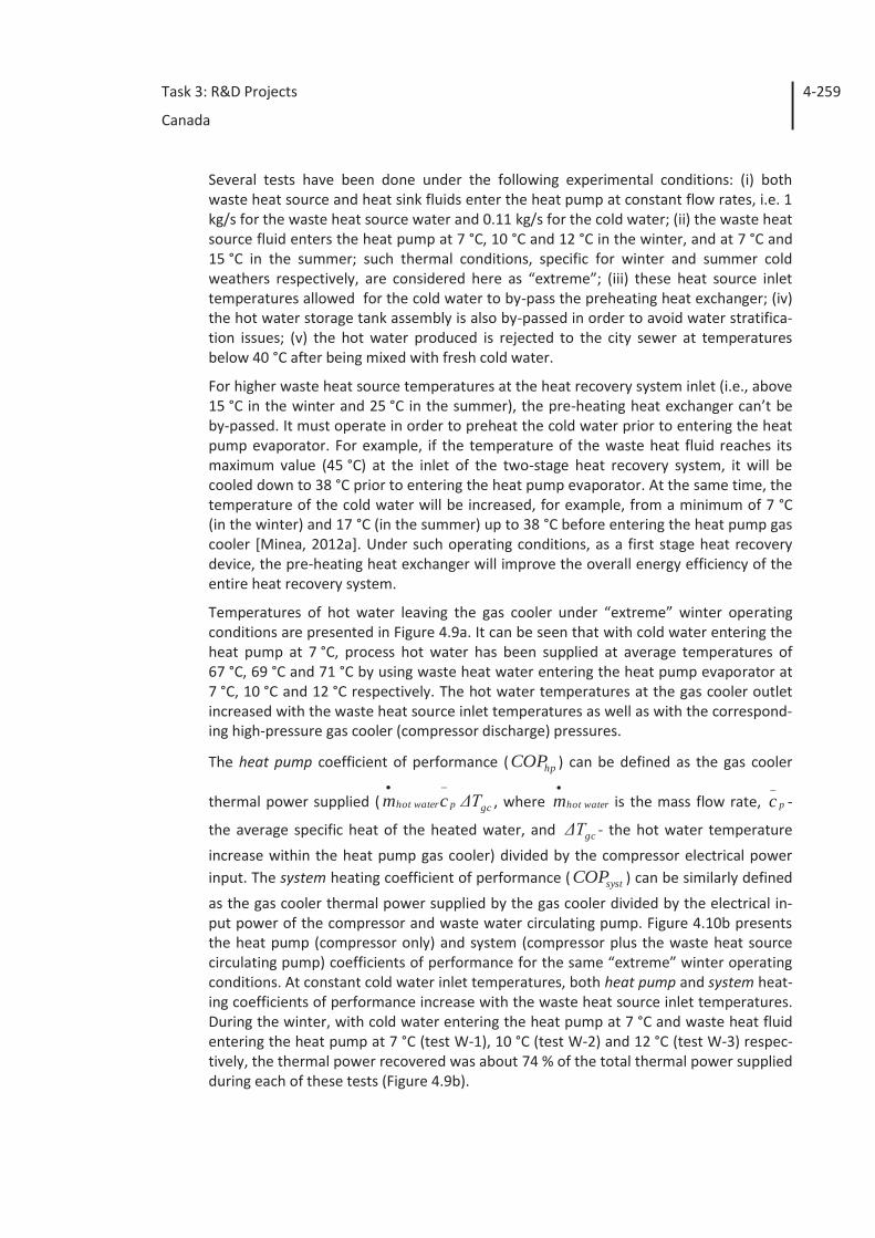
Task 3: R&D Projects
Canada
4-259
Several tests have been done under the following experimental conditions: (i) both waste heat source and heat sink fluids enter the heat pump at constant flow rates, i.e. 1 kg/s for the waste heat source water and 0.11 kg/s for the cold water; (ii) the waste heat source fluid enters the heat pump at 7 °C, 10 °C and 12 °C in the winter, and at 7 °C and 15 °C in the summer; such thermal conditions, specific for winter and summer cold weathers respectively, are considered here as “extreme”; (iii) these heat source inlet temperatures allowed for the cold water to by-pass the preheating heat exchanger; (iv) the hot water storage tank assembly is also by-passed in order to avoid water stratifica-tion issues; (v) the hot water produced is rejected to the city sewer at temperatures below 40 °C after being mixed with fresh cold water.
For higher waste heat source temperatures at the heat recovery system inlet (i.e., above 15 °C in the winter and 25 °C in the summer), the pre-heating heat exchanger can’t be by-passed. It must operate in order to preheat the cold water prior to entering the heat pump evaporator. For example, if the temperature of the waste heat fluid reaches its maximum value (45 °C) at the inlet of the two-stage heat recovery system, it will be cooled down to 38 °C prior to entering the heat pump evaporator. At the same time, the temperature of the cold water will be increased, for example, from a minimum of 7 °C (in the winter) and 17 °C (in the summer) up to 38 °C before entering the heat pump gas cooler [Minea, 2012a]. Under such operating conditions, as a first stage heat recovery device, the pre-heating heat exchanger will improve the overall energy efficiency of the entire heat recovery system.
Temperatures of hot water leaving the gas cooler under “extreme” winter operating conditions are presented in Figure 4.9a. It can be seen that with cold water entering the heat pump at 7 °C, process hot water has been supplied at average temperatures of 67 °C, 69 °C and 71 °C by using waste heat water entering the heat pump evaporator at 7 °C, 10 °C and 12 °C respectively. The hot water temperatures at the gas cooler outlet increased with the waste heat source inlet temperatures as well as with the correspond-ing high-pressure gas cooler (compressor discharge) pressures.
The heat pump coefficient of performance ( hpCOP ) can be defined as the gas cooler
thermal power supplied ( gcphot water ΔTcm , where hot waterm is the mass flow rate, p
_
c -
the average specific heat of the heated water, and gcΔT - the hot water temperature
increase within the heat pump gas cooler) divided by the compressor electrical power input. The system heating coefficient of performance ( systCOP ) can be similarly defined
as the gas cooler thermal power supplied by the gas cooler divided by the electrical in-put power of the compressor and waste water circulating pump. Figure 4.10b presents the heat pump (compressor only) and system (compressor plus the waste heat source circulating pump) coefficients of performance for the same “extreme” winter operating conditions. At constant cold water inlet temperatures, both heat pump and system heat-ing coefficients of performance increase with the waste heat source inlet temperatures. During the winter, with cold water entering the heat pump at 7 °C and waste heat fluid entering the heat pump at 7 °C (test W-1), 10 °C (test W-2) and 12 °C (test W-3) respec-tively, the thermal power recovered was about 74 % of the total thermal power supplied during each of these tests (Figure 4.9b).
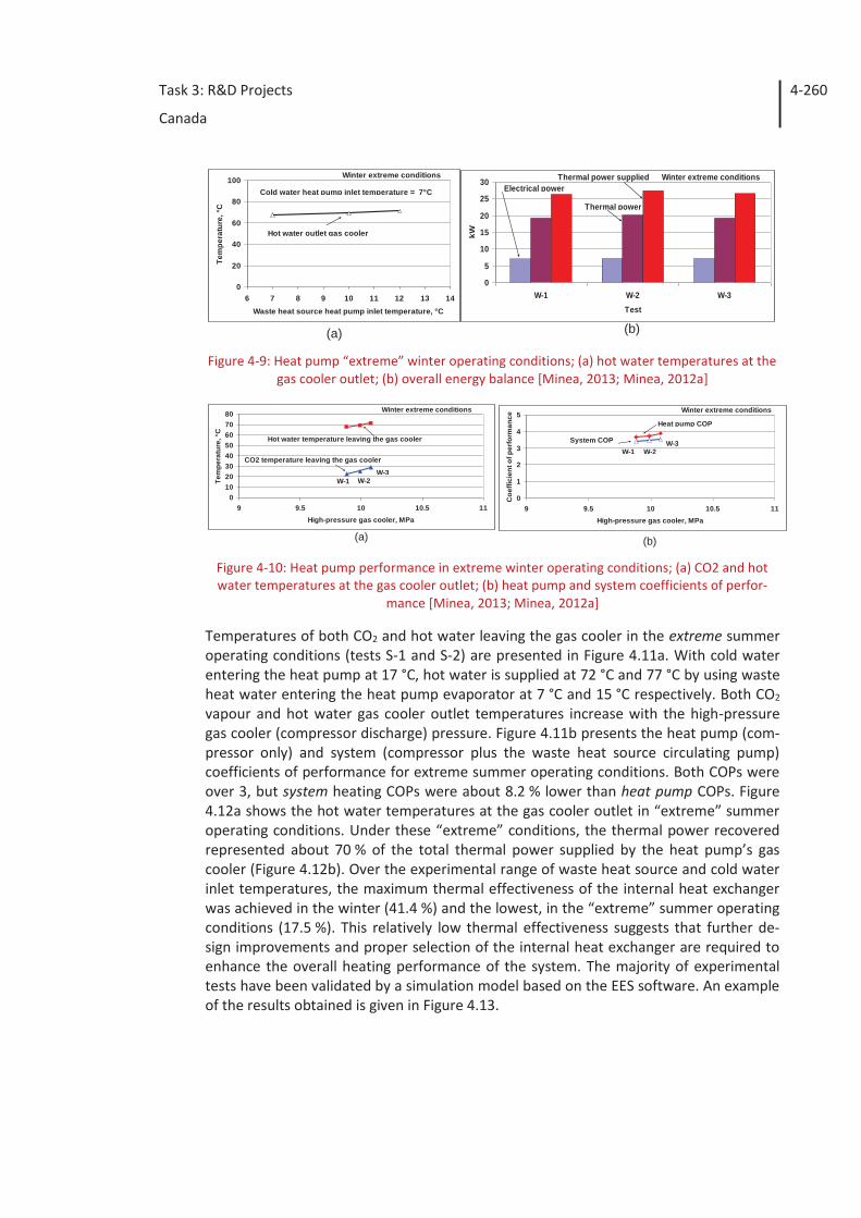
Task 3: R&D Projects
Canada
4-260
Figure 4-9: Heat pump “extreme” winter operating conditions; (a) hot water temperatures at the
gas cooler outlet; (b) overall energy balance [Minea, 2013; Minea, 2012a]
Figure 4-10: Heat pump performance in extreme winter operating conditions; (a) CO2 and hot water temperatures at the gas cooler outlet; (b) heat pump and system coefficients of perfor-
mance [Minea, 2013; Minea, 2012a]
Temperatures of both CO2 and hot water leaving the gas cooler in the extreme summer operating conditions (tests S-1 and S-2) are presented in Figure 4.11a. With cold water entering the heat pump at 17 °C, hot water is supplied at 72 °C and 77 °C by using waste heat water entering the heat pump evaporator at 7 °C and 15 °C respectively. Both CO2 vapour and hot water gas cooler outlet temperatures increase with the high-pressure gas cooler (compressor discharge) pressure. Figure 4.11b presents the heat pump (com-pressor only) and system (compressor plus the waste heat source circulating pump) coefficients of performance for extreme summer operating conditions. Both COPs were over 3, but system heating COPs were about 8.2 % lower than heat pump COPs. Figure 4.12a shows the hot water temperatures at the gas cooler outlet in “extreme” summer operating conditions. Under these “extreme” conditions, the thermal power recovered represented about 70 % of the total thermal power supplied by the heat pump’s gas cooler (Figure 4.12b). Over the experimental range of waste heat source and cold water inlet temperatures, the maximum thermal effectiveness of the internal heat exchanger was achieved in the winter (41.4 %) and the lowest, in the “extreme” summer operating conditions (17.5 %). This relatively low thermal effectiveness suggests that further de-sign improvements and proper selection of the internal heat exchanger are required to enhance the overall heating performance of the system. The majority of experimental tests have been validated by a simulation model based on the EES software. An example of the results obtained is given in Figure 4.13.
(b)(a)
0
20
40
60
80
100
6 7 8 9 10 11 12 13 14Waste heat source heat pump inlet temperature, °C
Tem
pera
ture
, °C
Cold water heat pump inlet temperature = 7°C
Hot water outlet gas cooler
Winter extreme conditions
0
5
10
15
20
25
30
W-1 W-2 W-3Test
kW
Electrical power Thermal power supplied
Thermal power
Winter extreme conditions
01020304050607080
9 9.5 10 10.5 11High-pressure gas cooler, MPa
Tem
pera
ture
, °C
CO2 temperature leaving the gas cooler
Hot water temperature leaving the gas cooler
W-1 W-2W-3
Winter extreme conditions
0
1
2
3
4
5
9 9.5 10 10.5 11High-pressure gas cooler, MPa
Coe
ffici
ent o
f per
form
ance
Winter extreme conditions
W-1 W-2W-3
Heat pump COP
System COP
(a) (b)
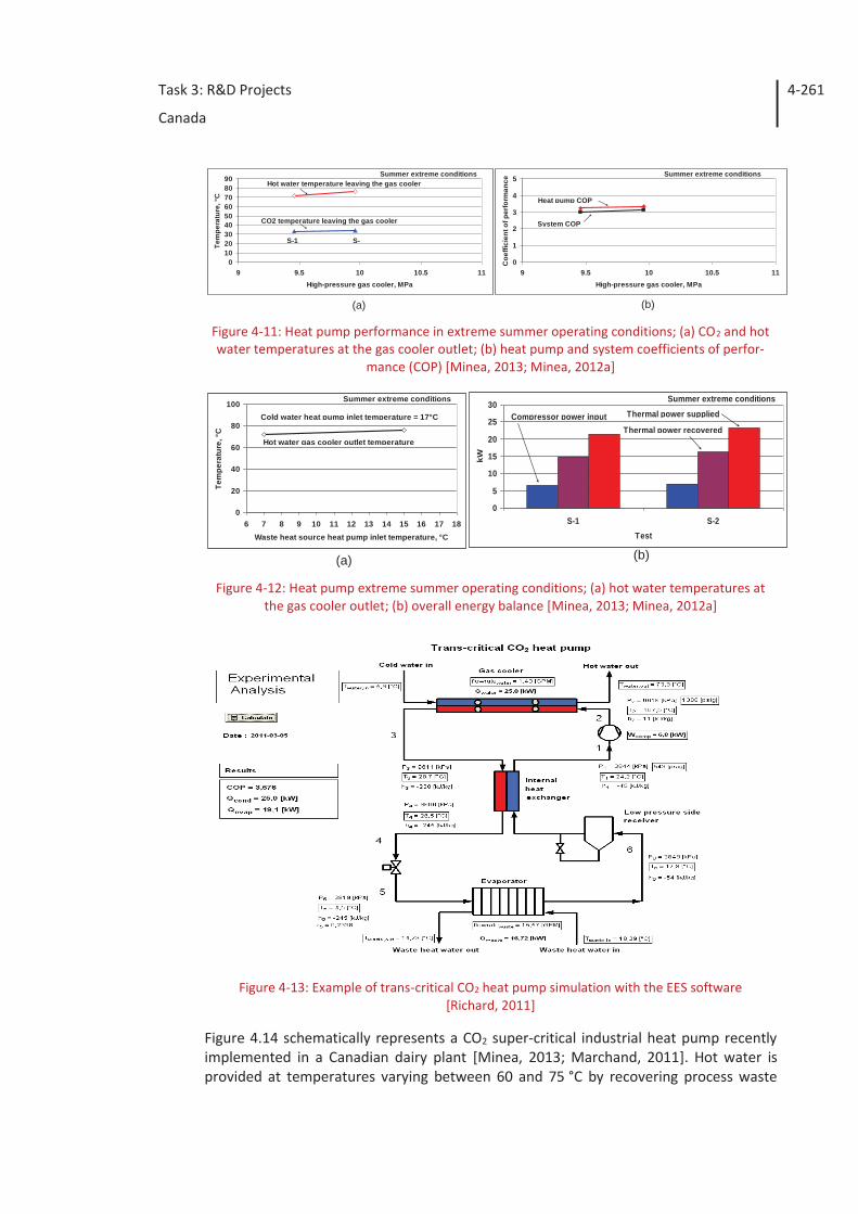
Task 3: R&D Projects
Canada
4-261
Figure 4-11: Heat pump performance in extreme summer operating conditions; (a) CO2 and hot water temperatures at the gas cooler outlet; (b) heat pump and system coefficients of perfor-
mance (COP) [Minea, 2013; Minea, 2012a]
Figure 4-12: Heat pump extreme summer operating conditions; (a) hot water temperatures at
the gas cooler outlet; (b) overall energy balance [Minea, 2013; Minea, 2012a]
Figure 4-13: Example of trans-critical CO2 heat pump simulation with the EES software
[Richard, 2011]
Figure 4.14 schematically represents a CO2 super-critical industrial heat pump recently implemented in a Canadian dairy plant [Minea, 2013; Marchand, 2011]. Hot water is provided at temperatures varying between 60 and 75 °C by recovering process waste
(a) (b)
0102030405060708090
9 9.5 10 10.5 11High-pressure gas cooler, MPa
Tem
pera
ture
, °C
Summer extreme conditions
CO2 temperature leaving the gas cooler
S-1 S-
Hot water temperature leaving the gas cooler
0
1
2
3
4
5
9 9.5 10 10.5 11High-pressure gas cooler, MPa
Coe
ffici
ent o
f per
form
ance
Summer extreme conditions
Heat pump COP
System COP
(b)(a)
0
20
40
60
80
100
6 7 8 9 10 11 12 13 14 15 16 17 18Waste heat source heat pump inlet temperature, °C
Tem
pera
ture
, °C
Cold water heat pump inlet temperature = 17°C
Hot water gas cooler outlet temperature
Summer extreme conditions
0
5
10
15
20
25
30
S-1 S-2Test
kW
Summer extreme conditions
Compressor power inputThermal power recovered
Thermal power supplied
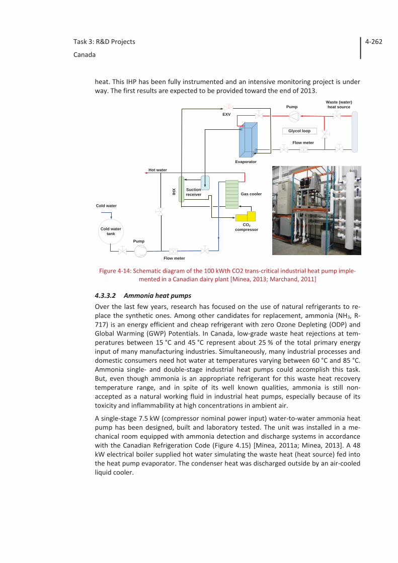
Task 3: R&D Projects
Canada
4-262
heat. This IHP has been fully instrumented and an intensive monitoring project is under way. The first results are expected to be provided toward the end of 2013.
Figure 4-14: Schematic diagram of the 100 kWth CO2 trans-critical industrial heat pump imple-
mented in a Canadian dairy plant [Minea, 2013; Marchand, 2011]
4.3.3.2 Ammonia heat pumps Over the last few years, research has focused on the use of natural refrigerants to re-place the synthetic ones. Among other candidates for replacement, ammonia (NH3, R-717) is an energy efficient and cheap refrigerant with zero Ozone Depleting (ODP) and Global Warming (GWP) Potentials. In Canada, low-grade waste heat rejections at tem-peratures between 15 °C and 45 °C represent about 25 % of the total primary energy input of many manufacturing industries. Simultaneously, many industrial processes and domestic consumers need hot water at temperatures varying between 60 °C and 85 °C. Ammonia single- and double-stage industrial heat pumps could accomplish this task. But, even though ammonia is an appropriate refrigerant for this waste heat recovery temperature range, and in spite of its well known qualities, ammonia is still non-accepted as a natural working fluid in industrial heat pumps, especially because of its toxicity and inflammability at high concentrations in ambient air.
A single-stage 7.5 kW (compressor nominal power input) water-to-water ammonia heat pump has been designed, built and laboratory tested. The unit was installed in a me-chanical room equipped with ammonia detection and discharge systems in accordance with the Canadian Refrigeration Code (Figure 4.15) [Minea, 2011a; Minea, 2013]. A 48 kW electrical boiler supplied hot water simulating the waste heat (heat source) fed into the heat pump evaporator. The condenser heat was discharged outside by an air-cooled liquid cooler.
Gas cooler
Evaporator
SuctionreceiverIH
X
Pump
CO2compressor
Hot water
EXV
Cold watertank
Pump
Glycol loop
Flow meter
Flow meter
Cold water
Waste (water)heat source
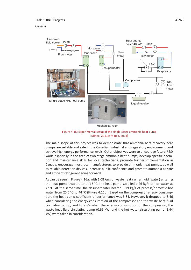
Task 3: R&D Projects
Canada
4-263
Figure 4-15: Experimental setup of the single-stage ammonia heat pump
[Minea, 2011a; Minea, 2013]
The main scope of this project was to demonstrate that ammonia heat recovery heat pumps are reliable and safe in the Canadian industrial and regulatory environment, and achieve high energy performance levels. Other objectives were to encourage future R&D work, especially in the area of two-stage ammonia heat pumps, develop specific opera-tion and maintenance skills for local technicians, promote further implementation in Canada, encourage most local manufacturers to provide ammonia heat pumps, as well as reliable detection devices, increase public confidence and promote ammonia as safe and efficient refrigerant going forward.
As can be seen in Figure 4.16a, with 1.08 kg/s of waste heat carrier fluid (water) entering the heat pump evaporator at 15 °C, the heat pump supplied 1.26 kg/s of hot water at 42 °C. At the same time, the desuperheater heated 0.19 kg/s of process/domestic hot water from 25.5 °C to 44 °C (Figure 4.16b). Based on the compressor energy consump-tion, the heat pump coefficient of performance was 3.84. However, it dropped to 3.46 when considering the energy consumption of the compressor and the waste heat fluid circulating pump, and to 2.85 when the energy consumption of the compressor, the waste heat fluid circulating pump (0.65 kW) and the hot water circulating pump (1.44 kW) were taken in consideration.
Compressor
Condenser
DesuperheaterEvaporator
NH3flow
meter
EXV
Air-cooledfluid cooler
Hot water
Heat sourceboiler 48 kW
Flow meterFlowmeterFlow meter
Liquid receiver
Mechanical room
Single-stage NH3 heat pump
PumpPump
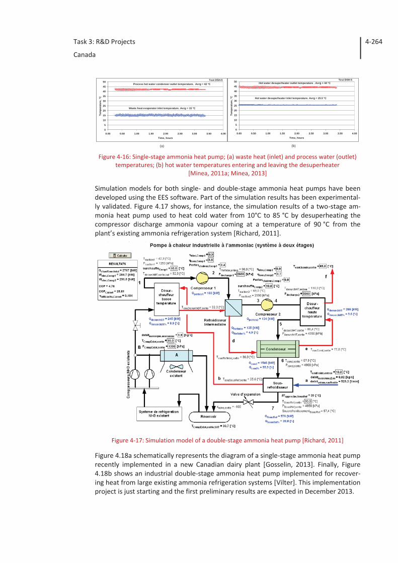
Task 3: R&D Projects
Canada
4-264
Figure 4-16: Single-stage ammonia heat pump; (a) waste heat (inlet) and process water (outlet)
temperatures; (b) hot water temperatures entering and leaving the desuperheater [Minea, 2011a; Minea, 2013]
Simulation models for both single- and double-stage ammonia heat pumps have been developed using the EES software. Part of the simulation results has been experimental-ly validated. Figure 4.17 shows, for instance, the simulation results of a two-stage am-monia heat pump used to heat cold water from 10°C to 85 °C by desuperheating the compressor discharge ammonia vapour coming at a temperature of 90 °C from the plant’s existing ammonia refrigeration system [Richard, 2011].
Figure 4-17: Simulation model of a double-stage ammonia heat pump [Richard, 2011]
Figure 4.18a schematically represents the diagram of a single-stage ammonia heat pump recently implemented in a new Canadian dairy plant [Gosselin, 2013]. Finally, Figure 4.18b shows an industrial double-stage ammonia heat pump implemented for recover-ing heat from large existing ammonia refrigeration systems [Vilter]. This implementation project is just starting and the first preliminary results are expected in December 2013.
0
5
10
15
20
25
30
35
40
45
50
0.00 0.50 1.00 1.50 2.00 2.50 3.00 3.50 4.00Time, hours
Tem
pera
ture
, °C
Test DSH-5
Waste heat evaporator inlet temperature. Avrg = 15 °C
Process hot water condenser outlet temperature. Avrg = 42 °C
0
5
10
15
20
25
30
35
40
45
50
0.00 0.50 1.00 1.50 2.00 2.50 3.00 3.50 4.00Time, hours
Tem
pera
ture
, °C
Test DSH-5
Hot water desuperheater inlet temperature. Avrg = 25.5 °C
Hot water desuperheater outlet temperature . Avrg = 44 °C
(a) (b)
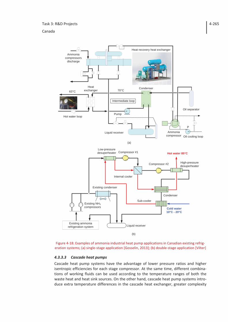
Task 3: R&D Projects
Canada
4-265
Figure 4-18: Examples of ammonia industrial heat pump applications in Canadian existing refrig-eration systems; (a) single-stage application [Gosselin, 2013]; (b) double-stage application [Vilter]
4.3.3.3 Cascade heat pumps Cascade heat pump systems have the advantage of lower pressure ratios and higher isentropic efficiencies for each stage compressor. At the same time, different combina-tions of working fluids can be used according to the temperature ranges of both the waste heat and heat sink sources. On the other hand, cascade heat pump systems intro-duce extra temperature differences in the cascade heat exchanger, greater complexity
Condenser
Intermediate loop
Heatexchanger
Hot water loop
Oil separator
63°C 70°C
Pump
Liquid receiver Ammoniacompressor Oil cooling loop
Heat recovery heat exchangerAmmonia
compressorsdischarge
P
Existing condenser
Existing ammoniarefrigeration system Liquid receiver
Sub-cooler
Condenser
Cold water10°C - 20°C
Hot water 85°C
High-pressuredesuperheater
Compressor #2
Compressor #1
Internal cooler
Existing NH3compressors
Low-pressuredesuperheater
(a)
(b)
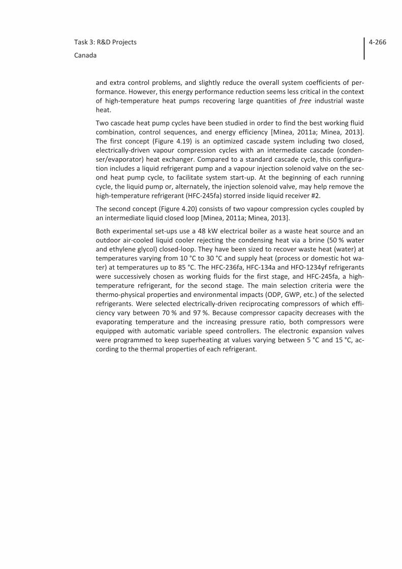
Task 3: R&D Projects
Canada
4-266
and extra control problems, and slightly reduce the overall system coefficients of per-formance. However, this energy performance reduction seems less critical in the context of high-temperature heat pumps recovering large quantities of free industrial waste heat.
Two cascade heat pump cycles have been studied in order to find the best working fluid combination, control sequences, and energy efficiency [Minea, 2011a; Minea, 2013]. The first concept (Figure 4.19) is an optimized cascade system including two closed, electrically-driven vapour compression cycles with an intermediate cascade (conden-ser/evaporator) heat exchanger. Compared to a standard cascade cycle, this configura-tion includes a liquid refrigerant pump and a vapour injection solenoid valve on the sec-ond heat pump cycle, to facilitate system start-up. At the beginning of each running cycle, the liquid pump or, alternately, the injection solenoid valve, may help remove the high-temperature refrigerant (HFC-245fa) storred inside liquid receiver #2.
The second concept (Figure 4.20) consists of two vapour compression cycles coupled by an intermediate liquid closed loop [Minea, 2011a; Minea, 2013].
Both experimental set-ups use a 48 kW electrical boiler as a waste heat source and an outdoor air-cooled liquid cooler rejecting the condensing heat via a brine (50 % water and ethylene glycol) closed-loop. They have been sized to recover waste heat (water) at temperatures varying from 10 °C to 30 °C and supply heat (process or domestic hot wa-ter) at temperatures up to 85 °C. The HFC-236fa, HFC-134a and HFO-1234yf refrigerants were successively chosen as working fluids for the first stage, and HFC-245fa, a high-temperature refrigerant, for the second stage. The main selection criteria were the thermo-physical properties and environmental impacts (ODP, GWP, etc.) of the selected refrigerants. Were selected electrically-driven reciprocating compressors of which effi-ciency vary between 70 % and 97 %. Because compressor capacity decreases with the evaporating temperature and the increasing pressure ratio, both compressors were equipped with automatic variable speed controllers. The electronic expansion valves were programmed to keep superheating at values varying between 5 °C and 15 °C, ac-cording to the thermal properties of each refrigerant.
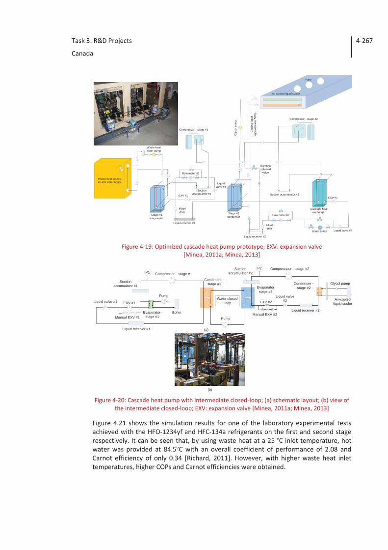
Task 3: R&D Projects
Canada
4-267
Figure 4-19: Optimized cascade heat pump prototype; EXV: expansion valve
[Minea, 2011a; Minea, 2013]
Figure 4-20: Cascade heat pump with intermediate closed-loop; (a) schematic layout; (b) view of
the intermediate closed-loop; EXV: expansion valve [Minea, 2011a; Minea, 2013]
Figure 4.21 shows the simulation results for one of the laboratory experimental tests achieved with the HFO-1234yf and HFC-134a refrigerants on the first and second stage respectively. It can be seen that, by using waste heat at a 25 °C inlet temperature, hot water was provided at 84.5°C with an overall coefficient of performance of 2.08 and Carnot efficiency of only 0.34 [Richard, 2011]. However, with higher waste heat inlet temperatures, higher COPs and Carnot efficiencies were obtained.
Stage #1evaporator
Stage #2condenser
Cascade heatexchanger
Waste heat source48-kW water boiler
Liquid receiver #1
Liquid receiver #2
Suctionaccumulator #1 Suction accumulator #2EXV #1
EXV #2
Liquid valve #2
Liquidvalve #1
Compressor – stage #1
Compressor - stage #2
Waste heatwater pump
Air-cooled liquid cooler
Coo
ling
liqui
d(g
lyco
l/wat
er50
%)
Gly
colp
ump
Filter/drier
Flow meter #1
Flow meter #2
Injectionsolenoid
valve
Fans
Liquid pump
Filter/drier
(b)
Evaporator-stage #1
Condenser –stage #2
Compresseur – stage #2
Boiler
Air-cooledliquid cooler
Compressor – stage #1
Pump
Glycol pump
EXV #1 EXV #2Liquid valve #1
Manual EXV #1Manual EXV #2
Liquid valve#2Water closed-
loop
Pump
Condenser –stage #1
Evaporatorstage #2
P2P1
Liquid receiver #1
Suctionaccumulator #1
Suctionaccumulator #2
Liquid receiver #2
(a)
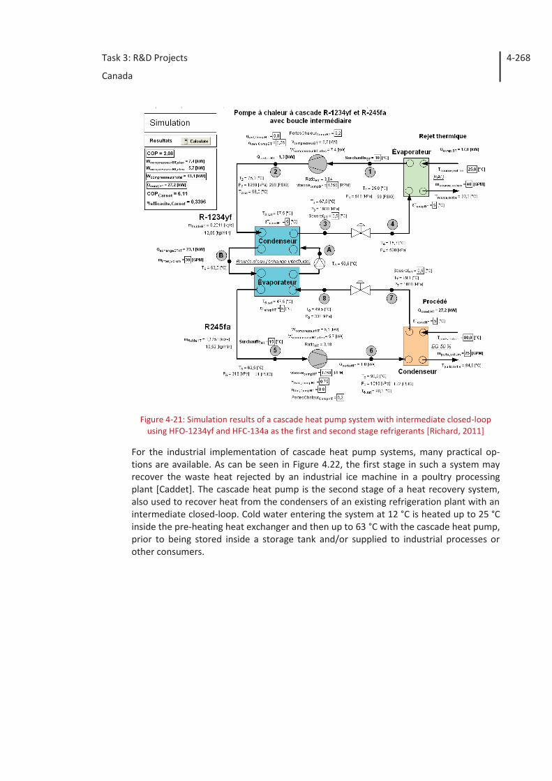
Task 3: R&D Projects
Canada
4-268
Figure 4-21: Simulation results of a cascade heat pump system with intermediate closed-loop
using HFO-1234yf and HFC-134a as the first and second stage refrigerants [Richard, 2011]
For the industrial implementation of cascade heat pump systems, many practical op-tions are available. As can be seen in Figure 4.22, the first stage in such a system may recover the waste heat rejected by an industrial ice machine in a poultry processing plant [Caddet]. The cascade heat pump is the second stage of a heat recovery system, also used to recover heat from the condensers of an existing refrigeration plant with an intermediate closed-loop. Cold water entering the system at 12 °C is heated up to 25 °C inside the pre-heating heat exchanger and then up to 63 °C with the cascade heat pump, prior to being stored inside a storage tank and/or supplied to industrial processes or other consumers.
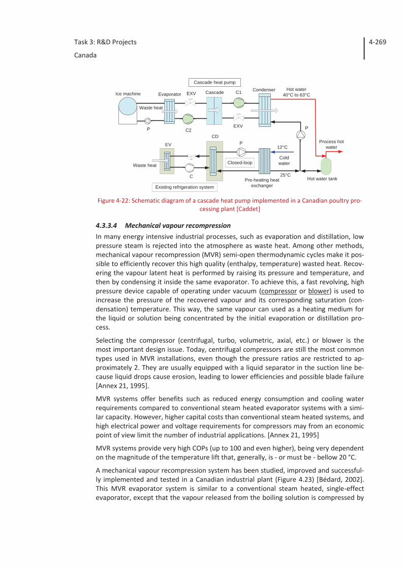
Task 3: R&D Projects
Canada
4-269
Figure 4-22: Schematic diagram of a cascade heat pump implemented in a Canadian poultry pro-
cessing plant [Caddet]
4.3.3.4 Mechanical vapour recompression In many energy intensive industrial processes, such as evaporation and distillation, low pressure steam is rejected into the atmosphere as waste heat. Among other methods, mechanical vapour recompression (MVR) semi-open thermodynamic cycles make it pos-sible to efficiently recover this high quality (enthalpy, temperature) wasted heat. Recov-ering the vapour latent heat is performed by raising its pressure and temperature, and then by condensing it inside the same evaporator. To achieve this, a fast revolving, high pressure device capable of operating under vacuum (compressor or blower) is used to increase the pressure of the recovered vapour and its corresponding saturation (con-densation) temperature. This way, the same vapour can used as a heating medium for the liquid or solution being concentrated by the initial evaporation or distillation pro-cess.
Selecting the compressor (centrifugal, turbo, volumetric, axial, etc.) or blower is the most important design issue. Today, centrifugal compressors are still the most common types used in MVR installations, even though the pressure ratios are restricted to ap-proximately 2. They are usually equipped with a liquid separator in the suction line be-cause liquid drops cause erosion, leading to lower efficiencies and possible blade failure [Annex 21, 1995].
MVR systems offer benefits such as reduced energy consumption and cooling water requirements compared to conventional steam heated evaporator systems with a simi-lar capacity. However, higher capital costs than conventional steam heated systems, and high electrical power and voltage requirements for compressors may from an economic point of view limit the number of industrial applications. [Annex 21, 1995]
MVR systems provide very high COPs (up to 100 and even higher), being very dependent on the magnitude of the temperature lift that, generally, is - or must be - bellow 20 °C.
A mechanical vapour recompression system has been studied, improved and successful-ly implemented and tested in a Canadian industrial plant (Figure 4.23) [Bédard, 2002]. This MVR evaporator system is similar to a conventional steam heated, single-effect evaporator, except that the vapour released from the boiling solution is compressed by
Closed-loop
P
Coldwater
Process hotwater
Hot water tank
CondenserCascade C1EXVEvaporatorHot water
40°C to 63°C
25°CPre-heating heat
exchanger
Waste heat
12°C
P
Ice machine
C2P EXV
Cascade heat pump
C
Existing refrigeration system
EV
CD
Waste heat
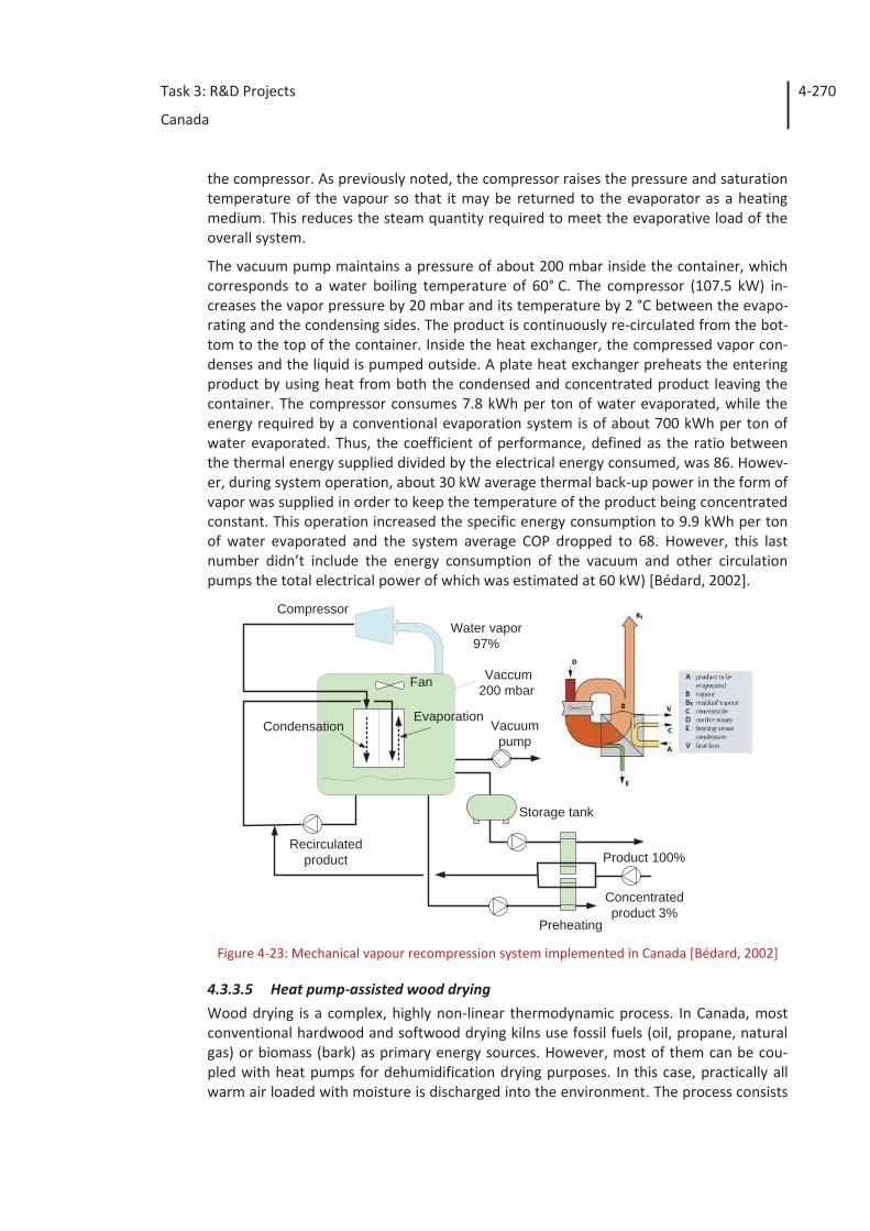
Task 3: R&D Projects
Canada
4-270
the compressor. As previously noted, the compressor raises the pressure and saturation temperature of the vapour so that it may be returned to the evaporator as a heating medium. This reduces the steam quantity required to meet the evaporative load of the overall system.
The vacuum pump maintains a pressure of about 200 mbar inside the container, which corresponds to a water boiling temperature of 60° C. The compressor (107.5 kW) in-creases the vapor pressure by 20 mbar and its temperature by 2 °C between the evapo-rating and the condensing sides. The product is continuously re-circulated from the bot-tom to the top of the container. Inside the heat exchanger, the compressed vapor con-denses and the liquid is pumped outside. A plate heat exchanger preheats the entering product by using heat from both the condensed and concentrated product leaving the container. The compressor consumes 7.8 kWh per ton of water evaporated, while the energy required by a conventional evaporation system is of about 700 kWh per ton of water evaporated. Thus, the coefficient of performance, defined as the ratio between the thermal energy supplied divided by the electrical energy consumed, was 86. Howev-er, during system operation, about 30 kW average thermal back-up power in the form of vapor was supplied in order to keep the temperature of the product being concentrated constant. This operation increased the specific energy consumption to 9.9 kWh per ton of water evaporated and the system average COP dropped to 68. However, this last number didn’t include the energy consumption of the vacuum and other circulation pumps the total electrical power of which was estimated at 60 kW) [Bédard, 2002].
Figure 4-23: Mechanical vapour recompression system implemented in Canada [Bédard, 2002]
4.3.3.5 Heat pump-assisted wood drying Wood drying is a complex, highly non-linear thermodynamic process. In Canada, most conventional hardwood and softwood drying kilns use fossil fuels (oil, propane, natural gas) or biomass (bark) as primary energy sources. However, most of them can be cou-pled with heat pumps for dehumidification drying purposes. In this case, practically all warm air loaded with moisture is discharged into the environment. The process consists
Product 100%
Concentratedproduct 3%
Vacuumpump
Preheating
CondensationEvaporation
Fan
CompressorWater vapor
97%
Recirculatedproduct
Vaccum200 mbar
Storage tank
Task 3: R&D Projects
Canada
4-271
in saving energy through re-heating and dehumidifying the process air. Warm dry air is led over the surface of the wood boards to be dried, and its very low relative humidity helps remove moisture from the wood. The water vapour picked up condenses on the externally finned heat transfer surface of the heat pump evaporator, and then is heated again by passing through the heat pump condenser. Heat is thus recovered from the dryer hot and humid air, and the recovered sensible and latent heat is used to reheat the dehumidified drying air. Other advantages include proper control of product mois-ture content, reduced energy consumption and relatively short pay-back periods for the industrial drying heat pumps. However, when compared with basic hot air convective dryers, drying heat pumps involve higher capital and maintenance costs, are more com-plex to operate and require qualified operators.
a) Low-temperature drying heat pump
A low-temperature laboratory-scale prototype consisting of a 13 m3 forced-air dryer with variable-speed fans coupled to a 5.6 kW (compressor nominal power input) low-temperature heat pump (Figure 4.24) has been extensively studied for drying Canadian hardwood species through dehumidification [29, 30]. Hardwood, such as sugar maple and white and yellow birch, has relatively complex cell structures, and in Eastern Cana-da, their average green moisture content varies between 6 5% and 72 %. For these spe-cies, drying is an essential step in the manufacturing process (furniture, etc.). The dryer is equipped with steam and electrical backup heating coils. Steam is supplied at variable flow rates by a natural gas-fired steam boiler. The air flow rate over the lumber surface is maintained sufficiently high to provide a rapid air exchange and minimise dead spots. To ensure uniform heating and drying, the direction of the air flow is periodically re-versed. The heat pump, including the compressor, blower, evaporator, condenser, sub-cooler, refrigeration piping and controls, is installed in a mechanical room next to the dryer. Based on the product actual moisture content, the drying schedules, as well as the heat pump hourly running times, are established prior to each drying cycle.
The heat pump compressor operating time was set in accordance with an intermittent drying schedule, as shown in Figure 4.25a [Minea, 2006; Minea, 2011b]. Both heating and dehumidification processes were controlled by the actual wet-bulb temperature of the air inside the drier. At the beginning of each drying cycle, the compressor hourly running ratio was pre-set at 100 %, and then it was continuously adjusted between 0 and 100 % in order to have the actual wet- and dry-bulb temperatures in the dryer prac-tically equal to their setting points. Under such schedule if, for example, the compressor hourly running time was set at 60 %, it ran for 30 minutes and shut down during the next 20 minutes. After the heat pump started, the compressor running time was in-creased when the actual wet-bulb temperature was above the upper limit, and de-creased when it was below the lower limit. Figure 4.25b shows the cumulative amount of water extracted during a typical drying cycle with yellow birch using the intermittent drying strategy shown in Figure 4.25a.
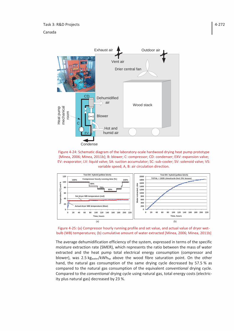
Task 3: R&D Projects
Canada
4-272
Figure 4-24: Schematic diagram of the laboratory-scale hardwood drying heat pump prototype [Minea, 2006; Minea, 2011b]; B: blower; C: compressor; CD: condenser; EXV: expansion valve;
EV: evaporator; LV: liquid valve; SA: suction accumulator; SC: sub-cooler; SV: solenoid valve; VS: variable speed; A, B: air circulation direction.
Figure 4-25: (a) Compressor hourly running profile and set value, and actual value of dryer wet-
bulb (WB) temperatures; (b) cumulative amount of water extracted [Minea, 2006; Minea, 2011b]
The average dehumidification efficiency of the system, expressed in terms of the specific moisture extraction rate (SMER), which represents the ratio between the mass of water extracted and the heat pump total electrical energy consumption (compressor and blower), was 2.5 kgwater/kWhhp above the wood fibre saturation point. On the other hand, the natural gas consumption of the same drying cycle decreased by 57.5 % as compared to the natural gas consumption of the equivalent conventional drying cycle. Compared to the conventional drying cycle using natural gas, total energy costs (electric-ity plus natural gas) decreased by 23 %.
Wood stack
Outdoor airExhaust air
Condense
Hot andhumid air
Blower
Hea
tpum
pm
echa
nica
lro
om
C
Vent air
EV
Drier central fan
CD Dehumidifiedair
(a) (b)
0
20
40
60
80
100
120
0 20 40 60 80 100 120 140 160 180 200 220
Time, hours
Tem
pera
ture
(°C
) and
%
Test 5H: hybrid (yellow birch)
Set dryer WB temperature (red)
100%
85%
75%65%
100%
Actual dryer WB temperature (blue)
Compressor hourly running time (%)
0200400600800
100012001400160018002000
0 20 40 60 80 100 120 140 160 180 200 220
Time, hours
Wat
er e
xtra
cted
, Litr
e
Test 5H: hybrid (yellow birch)
TOTAL = 1935 Litres/cycle (incl. 5% losses)
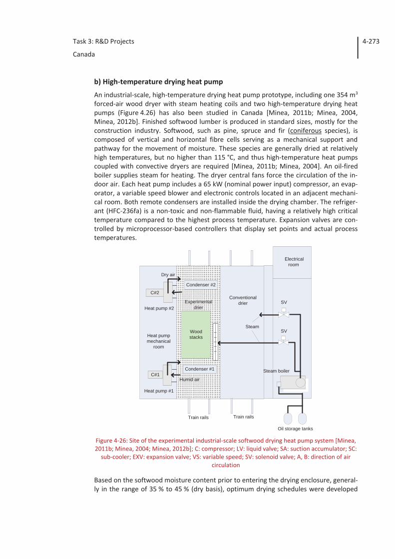
Task 3: R&D Projects
Canada
4-273
b) High-temperature drying heat pump
An industrial-scale, high-temperature drying heat pump prototype, including one 354 m3 forced-air wood dryer with steam heating coils and two high-temperature drying heat pumps (Figure 4.26) has also been studied in Canada [Minea, 2011b; Minea, 2004, Minea, 2012b]. Finished softwood lumber is produced in standard sizes, mostly for the construction industry. Softwood, such as pine, spruce and fir (coniferous species), is composed of vertical and horizontal fibre cells serving as a mechanical support and pathway for the movement of moisture. These species are generally dried at relatively high temperatures, but no higher than 115 °C, and thus high-temperature heat pumps coupled with convective dryers are required [Minea, 2011b; Minea, 2004]. An oil-fired boiler supplies steam for heating. The dryer central fans force the circulation of the in-door air. Each heat pump includes a 65 kW (nominal power input) compressor, an evap-orator, a variable speed blower and electronic controls located in an adjacent mechani-cal room. Both remote condensers are installed inside the drying chamber. The refriger-ant (HFC-236fa) is a non-toxic and non-flammable fluid, having a relatively high critical temperature compared to the highest process temperature. Expansion valves are con-trolled by microprocessor-based controllers that display set points and actual process temperatures.
Figure 4-26: Site of the experimental industrial-scale softwood drying heat pump system [Minea, 2011b; Minea, 2004; Minea, 2012b]; C: compressor; LV: liquid valve; SA: suction accumulator; SC:
sub-cooler; EXV: expansion valve; VS: variable speed; SV: solenoid valve; A, B: direction of air circulation
Based on the softwood moisture content prior to entering the drying enclosure, general-ly in the range of 35 % to 45 % (dry basis), optimum drying schedules were developed
Condenser #1C#1
C#2
Experimentaldrier
Conventionaldrier
Oil storage tanks
Steam boiler
Steam
Heat pump #1
Heat pumpmechanical
room
Electricalroom
Train rails Train rails
Heat pump #2
Woodstacks
Condenser #2
Humid air
Dry air
SV
SV
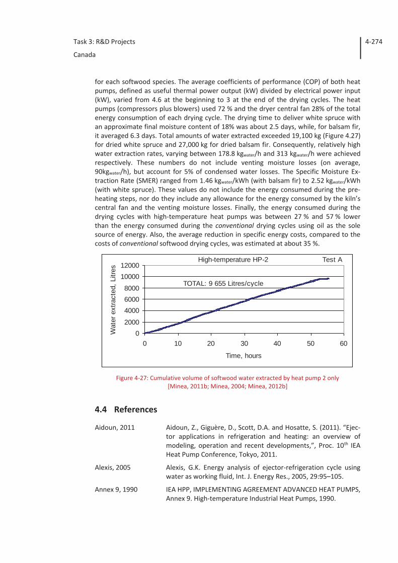
Task 3: R&D Projects
Canada
4-274
for each softwood species. The average coefficients of performance (COP) of both heat pumps, defined as useful thermal power output (kW) divided by electrical power input (kW), varied from 4.6 at the beginning to 3 at the end of the drying cycles. The heat pumps (compressors plus blowers) used 72 % and the dryer central fan 28% of the total energy consumption of each drying cycle. The drying time to deliver white spruce with an approximate final moisture content of 18% was about 2.5 days, while, for balsam fir, it averaged 6.3 days. Total amounts of water extracted exceeded 19,100 kg (Figure 4.27) for dried white spruce and 27,000 kg for dried balsam fir. Consequently, relatively high water extraction rates, varying between 178.8 kgwater/h and 313 kgwater/h were achieved respectively. These numbers do not include venting moisture losses (on average, 90kgwater/h), but account for 5% of condensed water losses. The Specific Moisture Ex-traction Rate (SMER) ranged from 1.46 kgwater/kWh (with balsam fir) to 2.52 kgwater/kWh (with white spruce). These values do not include the energy consumed during the pre-heating steps, nor do they include any allowance for the energy consumed by the kiln’s central fan and the venting moisture losses. Finally, the energy consumed during the drying cycles with high-temperature heat pumps was between 27 % and 57 % lower than the energy consumed during the conventional drying cycles using oil as the sole source of energy. Also, the average reduction in specific energy costs, compared to the costs of conventional softwood drying cycles, was estimated at about 35 %.
Figure 4-27: Cumulative volume of softwood water extracted by heat pump 2 only
[Minea, 2011b; Minea, 2004; Minea, 2012b]
4.4 References
Aidoun, 2011 Aidoun, Z., Giguère, D., Scott, D.A. and Hosatte, S. (2011). “Ejec-tor applications in refrigeration and heating: an overview of modeling, operation and recent developments,”, Proc. 10th IEA Heat Pump Conference, Tokyo, 2011.
Alexis, 2005 Alexis, G.K. Energy analysis of ejector-refrigeration cycle using water as working fluid, Int. J. Energy Res., 2005, 29:95–105.
Annex 9, 1990 IEA HPP, IMPLEMENTING AGREEMENT ADVANCED HEAT PUMPS, Annex 9. High-temperature Industrial Heat Pumps, 1990.
02000
400060008000
1000012000
0 10 20 30 40 50 60
Time, hours
Wat
er e
xtra
cted
, Litr
es
Test AHigh-temperature HP-2
TOTAL: 9 655 Litres/cycle
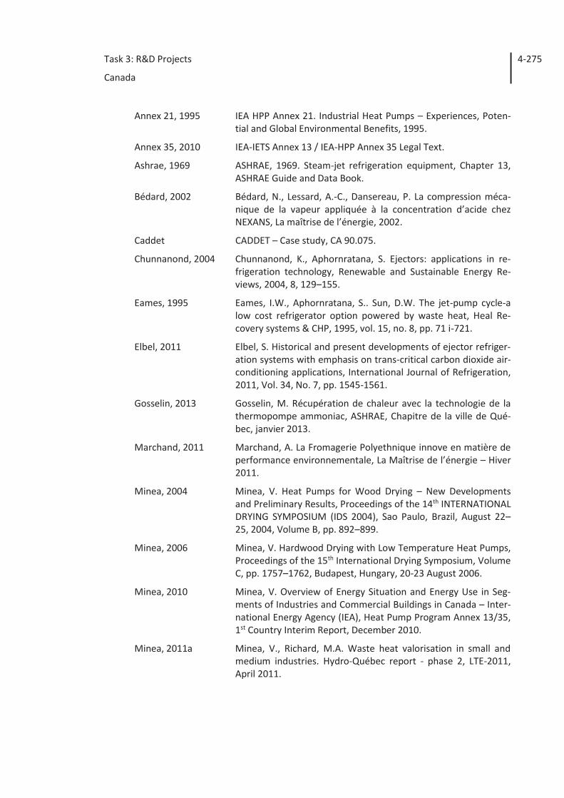
Task 3: R&D Projects
Canada
4-275
Annex 21, 1995 IEA HPP Annex 21. Industrial Heat Pumps – Experiences, Poten-tial and Global Environmental Benefits, 1995.
Annex 35, 2010 IEA-IETS Annex 13 / IEA-HPP Annex 35 Legal Text.
Ashrae, 1969 ASHRAE, 1969. Steam-jet refrigeration equipment, Chapter 13, ASHRAE Guide and Data Book.
Bédard, 2002 Bédard, N., Lessard, A.-C., Dansereau, P. La compression méca-nique de la vapeur appliquée à la concentration d’acide chez NEXANS, La maîtrise de l’énergie, 2002.
Caddet CADDET – Case study, CA 90.075.
Chunnanond, 2004 Chunnanond, K., Aphornratana, S. Ejectors: applications in re-frigeration technology, Renewable and Sustainable Energy Re-views, 2004, 8, 129–155.
Eames, 1995 Eames, I.W., Aphornratana, S.. Sun, D.W. The jet-pump cycle-a low cost refrigerator option powered by waste heat, Heal Re-covery systems & CHP, 1995, vol. 15, no. 8, pp. 71 i-721.
Elbel, 2011 Elbel, S. Historical and present developments of ejector refriger-ation systems with emphasis on trans-critical carbon dioxide air-conditioning applications, International Journal of Refrigeration, 2011, Vol. 34, No. 7, pp. 1545-1561.
Gosselin, 2013 Gosselin, M. Récupération de chaleur avec la technologie de la thermopompe ammoniac, ASHRAE, Chapitre de la ville de Qué-bec, janvier 2013.
Marchand, 2011 Marchand, A. La Fromagerie Polyethnique innove en matière de performance environnementale, La Maîtrise de l’énergie – Hiver 2011.
Minea, 2004 Minea, V. Heat Pumps for Wood Drying – New Developments and Preliminary Results, Proceedings of the 14th INTERNATIONAL DRYING SYMPOSIUM (IDS 2004), Sao Paulo, Brazil, August 22–25, 2004, Volume B, pp. 892–899.
Minea, 2006 Minea, V. Hardwood Drying with Low Temperature Heat Pumps, Proceedings of the 15th International Drying Symposium, Volume C, pp. 1757–1762, Budapest, Hungary, 20-23 August 2006.
Minea, 2010 Minea, V. Overview of Energy Situation and Energy Use in Seg-ments of Industries and Commercial Buildings in Canada – Inter-national Energy Agency (IEA), Heat Pump Program Annex 13/35, 1st Country Interim Report, December 2010.
Minea, 2011a Minea, V., Richard, M.A. Waste heat valorisation in small and medium industries. Hydro-Québec report - phase 2, LTE-2011, April 2011.
Task 3: R&D Projects
Canada
4-276
Minea, 2011b Minea, V. INDUSTRIAL DRYING HEAT PUMPS. In: Refrigeration: Theory, Technology and Applications. 2011 Nova Science Pub-lishers, Inc., pp. 1-70.
Minea, 2012a Minea, V. Low-grade industrial waste heat recovery with CO2 trans-critical heat pumps in cold climates, 10th IIR Gustav Lo-rentzen Conference on Natural Refrigerants, Delft, The Nether-lands, 2012.
Minea, 2012b Minea, V. Using industrial heat pumps in sawmills for lumber drying. IEA HEAT PUMP CENTRE, NEWSLETTER, VOL. 30, No. 1/2012, pp. 19-25.
Minea, 2013 Minea, V. Valorisation des rejets thermiques dans les petites et moyennes enterprises, Hydro-Québec (LTE) report – phase 3, août 2013.
NEB, 2008 National Energy Board. Canadian Energy Overview, 2008. Energy Market Assessment, 2008.
Ouzzane, 2003 Ouzzane, M. and Aidoun, Z. Model development and numerical procedure for detailed ejector analysis and design, Applied Thermal Engineering, 2003, Vol. 23, pp. 2337-2351.
Pridasawas, 2006 Pridasawas, W. Solar-driven refrigeration systems with focus on the ejector cycle, PhD Thesis, Royal Institute of Technology, KTH, Sweden, ISBN 91-7178-449-7, 2006, 286 p.
Richard, 2011 Richard, M.A. Waste heat valorisation in small and medium in-dustries, Hydro-Québec report - phase II, LTE-RS-2011-002.2, April 2011.
Scott Scott, D., Sunye, R. Ejector thermally-driven heat pumps, CanmetEnergy, Canada.
Scott, 2008 Scott, D., Aidoun, Z., Bellache, O. and Ouzzane, M. (2008). CFD simulations of a supersonic ejector for use in refrigeration appli-cations, Proceedings of the International Refrigeration and Air Conditioning Conference at Purdue, July 14-17,
Scott, 2011 Scott, D.A., Aidoun, Z. and Ouzzane, M. An experimental investi-gation of an ejector for validating numerical simulations, Inter-national Journal of Refrigeration, 2011, Vol. 34, pp. 1717-1723.
Sherif, 1998 Sherif, S.A., Goswami, D.Y., Mathur, G.D., Iyer, S.V., Davanagere, B.S., Natarajan, S., Colacino, S. A Feasibility study of steam-jet re-frigeration, Int. j. energy res., 1998, 22, 1323- 1336.
Stricker, 2006 Stricker Associates Inc.. Market study on waste heat and re-quirements for cooling and refrigeration in Canadian industry, 2006.
Vilter www.vilter-emerson.com

Task 3: R&D Projects
Canada
4-277
Yu, 2006 Yu, J., Chen, H., Ren, Y., Li, Y. A new ejector refrigeration system with an additional jet pump, Applied Thermal Engineering, 2006, 26, 312–319.

Task 3: R&D Projects
Denmark
5-278
5 Denmark
5.1 Introduction
In 2010 the Danish Commission on Climate Change Policy published a report describing the road to a Danish energy system without fossil fuels by 2050. In the political system there is consensus about the Commission’s recommendations and thus, Danish energy research is to a high degree governed by these.
Figure 5-1: The Danish Commission on Climate Change Policy: “Green Energy – the Road to a
Danish Energy System without Fossil Fuels. Summary of the Commission’s considerations, results and recommendations”, published 28 September 2010.
In the report heat pumps are attributed a significant role in the future energy supply, as a link between energy produced by electricity and utilization of excess heat. To under-line the future role of heat pumps, Commission chair Katherine Richardson estimates that by 2050 between 25 % and 50 % of the district heat supply should be supplied by heat pumps. More than 60 % of the Danish households are heated by district heating.
The Refrigerant Situation
Denmark has stricter rules for use of synthetic refrigerants than most other countries. With regard to CFC and HCFC refrigerants, Denmark follows the international rules and thus, the former have been completely phased out whereas HCFCs (primarily R-22) must be phased out by 1 January 2015. As to HFC refrigerants, Denmark enforces a special rule allowing only plants with a 0.2-10 kg refrigerant filling. In practice, this means that industrial heat pumps only use natural refrigerants.
Task 3: R&D Projects
Denmark
5-279
Due to this, Denmark is in a strong position worldwide particularly in relation to re-search, testing and experience of natural refrigerants ammonia, CO2 and water vapour.
5.2 Ongoing R&D
In Denmark R&D on large scale heat pumps has primarily been utilized in district heating systems, with forward temperatures between 70 and 90 °C. Heat sources are typically at ambient or slightly higher temperatures and could be flue gas, surface water, thermal storages, treated sewage water etc. Technologies in focus are trans-critical CO2, ammo-nia and isobutene.
Today CO2 systems are the main choice for commercial refrigeration in Denmark and the thermodynamical properties in the trans-critical state makes CO2 suitable in heat pumps where the medium is heated from a temperature below 40 °C up till 70-90 °C, thus mak-ing it suitable in most district heating systems.
Ammonia systems arise from industrial cooling, where the primary difference in heat pumps is higher operating pressures. Traditionally ammonia heat pumps in Denmark have been either 25 or 40 bar systems reaching a maximum temperature of 50-55 °C and 70-75 °C respectively. Today new 50 and 60 bar screw and piston compressors are being developed and demonstrated. These systems exceed 90 °C.
Isobutene is a low pressure refrigerant that can be utilized using low pressure HFC com-ponents. Isobutene systems can heat water to around 85 °C using standard low pressure components.
Heat pumps in industrial applications
Applying heat pumps in industrial processes is often much more complicated than in district heating systems. Heat production cost is what district heating is about, meaning that the fuel savings heat pumps contribute to, is of major importance causing heat pumps to be profitable. In production companies, the product is the main focus. Here energy cost is not always one of the main competitive parameters, meaning that the only benefit a heat pump provides might not be particularly important.
In industrial processes, boilers can often be difficult to convert directly to heat pumps as heat pumps are dependent on a heat source and temperature levels. In traditional sys-tems these parameters is almost of no importance, meaning that the heat distribution systems are often build for high temperatures while heat recovery can be very difficult. This means that heat pumps in general must be built into specific processes as a heat recovery unit rather than a centralized heating system. This gets even more complex with inconsistency in timeline of heat source and demand.
Analysis of heat demands and requirements in industrial applications
To have an overview of the potential and technical requirements of using heat pumps in industrial processes, two assessment reports have been published in 2013. The two re-ports are carried out with different approaches meaning that the results are not a 100 % comparable and conclusive. However both reports give good indications of the possibili-ties in industries. The first report [Viegand, 2013] considers excess heat of industries in general and the potential of utilization in different ways both internal and external.
Task 3: R&D Projects
Denmark
5-280
Technical and economical obstacles are taken into account. The most important results of the first report [Viegand, 2013] are:
- ¼ of the Danish heat demand in industrial processes require a temperature of 60 °C or less
- ½ of the Danish heat demand in industrial processes require a temperature of 100 °C or less
- ½ of the Danish heat demand in industrial processes require higher tempera-tures than 100 °C.
The focus of the second report is more specific on using heat pumps in different pro-cesses where heat is recovered and utilized in the same process. External utilization of industrial waste heat is not considered. The potential is assessed for processes with temperature requirements of up to 180 °C and categorized in temperature lifts of re-spectively 20 K, 40 K and 70 K. A requirement of 180° C and a temperature lift of 20 K means that the heat source is 160° C whereas a lift of 70 K means that the source is 110 °C. The most important results of the second report [Weel, 2013] are:
- At a temperature lift of 70 K and delivering at 180 °C, around ½ of the heat de-mand considered can be produced by heat pumps
- At a temperature lift of 70 K and delivering at 100 °C, 75 % of the potential is possible
- At a temperature lift of 40 K around 35 % of the potential is possible. At this temperature lift it is only a small part of the potential that require higher tem-peratures than 100 °C
- At a temperature lift of 20 K around 25 % of the potential is possible. At this temperature lift it is only a negligible part of the potential that require higher temperatures than 100 °C
- About 90 % of the potential (regardless of temperatures) can be covered by heat pumps with a capacity of 2 MW-heat or more.
Both reports show that the majority of the potential require temperatures less than 100 °C, meaning that outlet temperatures is not a technical barrier in most cases. The assessments also show that there is some potential for heat pumps that only lifts 20 K, meaning that high COP values is possible while the heat capacities should in MW’s. There is only a small potential for heat pumps with capacities less than 1 MW.
Viegand, 2013 Analysis of utilization of industrial excess heat, Viegand & Maa-gøe, 2013
Weel, 2013 The potential for high temperature heat pumps in industrial application, Weel & Sandvig, 2013
5.3 Demonstration
There have been a number of demonstration projects in the last couple of years imple-menting large scale heat pumps, which have primarily been transcritical CO2 or high
Task 3: R&D Projects
Denmark
5-281
pressure ammonia systems. At the moment research and development is also in the fields of water vapor systems and the ammonia/water hybrid process.
The following three demonstration projects are relevant for industrial purposes:
“Development of Rotrex turbo compressor for water vapor compression”
The project aims to develop a new and competitive electric water vapor compressor. The compressor is based on the Danish "Rotrex" turbo compressor, which is currently used for the compression of air. The project will develop and test a prototype using wa-ter vapor at laboratory level. There has conducted preliminary tests and calculations of the compressor, using water vapor, and it has been verified that practice and theory are consistent. There are various types of compressors on the market today that can be used for the desired applications, but they are either very expensive, limited in capacity or insufficiently reliable.
Water vapor heat pumps differ from other types of heat pumps by high efficiency and low working pressure in the temperature range of 70 to 250 °C. Today systems are often custom made, which makes them very expensive and not profitable in heating applica-tions where other alternatives are available.
The Rotrex compressor could be integrated directly into existing steam systems as a stand alone unit or in combination with traditional heat pumps, where the water vapor compressor can boost the temperature level another 20-30 °C i.e. from 90 °C to 120 °C.
Generally, the target for this technology are industrial sectors using thermal heat in the temperature range of 50 to 200 °C - and the potential is vast.
On the following pages is a paper by Weel & Sandwig, Rotrex and DTI on using the turbo compressor for drying applications:
5.3.1 Energy efficient drying with a novel turbo compressor based high temperature heat pump
Abstract
Drying is one of the most energy intensive operations for preservation of product in many industries. One way to reduce the primary energy consumption for drying is to integrate a high-temperature heat pump to recover the latent heat in the exit stream from the drying process. Rotrex, Weel & Sandvig and DTI are developing a new high-speed radial turbo-compressor designed for steam. The compressor is derived from Rotrex suit of auto mobile turbochargers. The steam-compressor is the heart in the working cycle for a heat pump suitable for integration in a drying system. The new con-cept is based on a modular basis where compressors can be configured in parallel and serial to match the operational specification for the actual drying system. The COP value of the drying heat pump system typically will be between 4 and 6 depending on the ac-tual configuration. As working medium of the heat pump, steam is selected, because of its excellent thermodynamic properties at high temperatures to meet high COP values, non toxicity and zero greenhouse potential.
Introduction
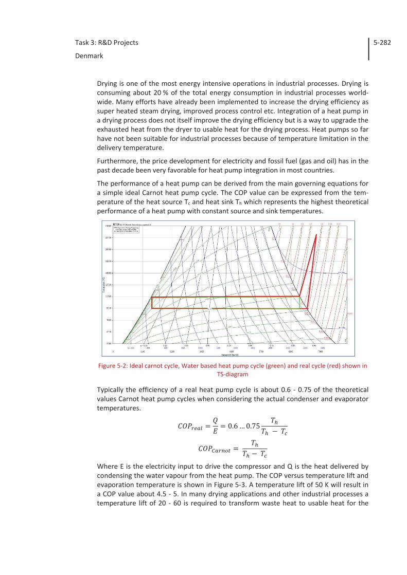
Task 3: R&D Projects
Denmark
5-282
Drying is one of the most energy intensive operations in industrial processes. Drying is consuming about 20 % of the total energy consumption in industrial processes world-wide. Many efforts have already been implemented to increase the drying efficiency as super heated steam drying, improved process control etc. Integration of a heat pump in a drying process does not itself improve the drying efficiency but is a way to upgrade the exhausted heat from the dryer to usable heat for the drying process. Heat pumps so far have not been suitable for industrial processes because of temperature limitation in the delivery temperature.
Furthermore, the price development for electricity and fossil fuel (gas and oil) has in the past decade been very favorable for heat pump integration in most countries.
The performance of a heat pump can be derived from the main governing equations for a simple ideal Carnot heat pump cycle. The COP value can be expressed from the tem-perature of the heat source Tc and heat sink Th which represents the highest theoretical performance of a heat pump with constant source and sink temperatures.
Figure 5-2: Ideal carnot cycle, Water based heat pump cycle (green) and real cycle (red) shown in TS-diagram
Typically the efficiency of a real heat pump cycle is about 0.6 - 0.75 of the theoretical values Carnot heat pump cycles when considering the actual condenser and evaporator temperatures.
Where E is the electricity input to drive the compressor and Q is the heat delivered by condensing the water vapour from the heat pump. The COP versus temperature lift and evaporation temperature is shown in Figure 5-3. A temperature lift of 50 K will result in a COP value about 4.5 - 5. In many drying applications and other industrial processes a temperature lift of 20 - 60 is required to transform waste heat to usable heat for the
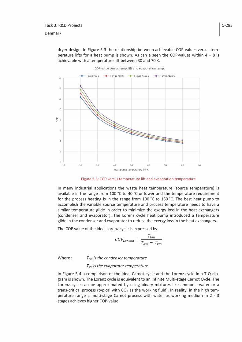
Task 3: R&D Projects
Denmark
5-283
dryer design. In Figure 5-3 the relationship between achievable COP-values versus tem-perature lifts for a heat pump is shown. As can e seen the COP-values within 4 – 8 is achievable with a temperature lift between 30 and 70 K.
Figure 5-3: COP versus temperature lift and evaporation temperature
In many industrial applications the waste heat temperature (source temperature) is available in the range from 100 °C to 40 °C or lower and the temperature requirement for the process heating is in the range from 100 °C to 150 °C. The best heat pump to accomplish the variable source temperature and process temperature needs to have a similar temperature glide in order to minimize the exergy loss in the heat exchangers (condenser and evaporator). The Lorenz cycle heat pump introduced a temperature glide in the condenser and evaporator to reduce the exergy loss in the heat exchangers.
The COP value of the ideal Lorenz cycle is expressed by:
Where : Thm is the condenser temperature
Tcm is the evaporator temperature
In Figure 5-4 a comparison of the ideal Carnot cycle and the Lorenz cycle in a T-Q dia-gram is shown. The Lorenz cycle is equivalent to an infinite Multi-stage Carnot Cycle. The Lorenz cycle can be approximated by using binary mixtures like ammonia-water or a trans-critical process (typical with CO2 as the working fluid). In reality, in the high tem-perature range a multi-stage Carnot process with water as working medium in 2 - 3 stages achieves higher COP-value.
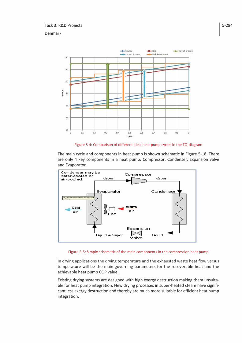
Task 3: R&D Projects
Denmark
5-284
Figure 5-4: Comparison of different ideal heat pump cycles in the TQ-diagram
The main cycle and components in heat pump is shown schematic in Figure 5-18. There are only 4 key components in a heat pump: Compressor, Condenser, Expansion valve and Evaporator.
Figure 5-5: Simple schematic of the main components in the compression heat pump
In drying applications the drying temperature and the exhausted waste heat flow versus temperature will be the main governing parameters for the recoverable heat and the achievable heat pump COP value.
Existing drying systems are designed with high exergy destruction making them unsuita-ble for heat pump integration. New drying processes in super-heated steam have signifi-cant less exergy destruction and thereby are much more suitable for efficient heat pump integration.

Task 3: R&D Projects
Denmark
5-285
A comparison of various working media for high-temperature heat pumping shows that water is the most efficient medium for condensing temperatures above 100 °C. In Figure 5-6 the COP-value for heat pumps cycles with different working fluid (water, butane, isobutane, CO2, NH3). For high-temperature operations it is clear that water is a superior working fluid. One drawback of water vapor is the relatively low vapor density when the evaporation temperature is below 80 °C which requires a high volumetric capacity of the heat pump compressor. Turbo compressors have very high volumetric flow rate capacity and are therefore preferable for water vapor heat pumps.
Figure 5-6: COP values of various heat pump refrigerants versus temperature lift. Evaporation
temperature is 70 °C
Compressor development and test
The turbo compressor for water vapor compression is derived from Rotrex’s line of au-tomotive turbochargers. The aluminum based compressor has been replaced with a new impeller made of titanium and housing and volute are designed to meet a higher pres-sure ratio and high efficiency and durability. New carbon based shaft seals are imple-mented to prevent steam or oil leaking at the shaft, see Figure 5-7.
The compressor suction volume is about 0.28 m3/s and the maximum pressure ratio with steam is approximately 3. A typical heat pump installation consisting of one turbo compressor unit can deliver about 450 kW heat at 130 °C when the suction pressure from the evaporator is 0.9 bar(a) (93 °C saturated steam temperature).
The Rotrex turbocharger has a unique traction geared compressor with excellent per-formance and approved for the automotive marked. The traction gear has a step-up ratio of 7.5 and the efficiency is 98.5 % at full load. The low-speed shaft of the traction gear is connected directly to a high speed motor (15,000 RPM) or a standard motor via a fast belt drive to assure a compressor impeller speed of up to 105,000 RPM. In Figure 5-7 and Figure 5-8 some principle drawings of the compressor assemble with traction gear, housing, impeller, volute etc. are presented.
The traction gear is lubricated by an internal oil pump which maintains a safe oil film on the traction (or friction) parts and circulates the oil through the external oil cooler.
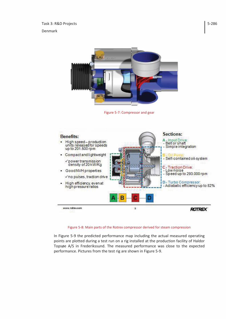
Task 3: R&D Projects
Denmark
5-286
Figure 5-7: Compressor and gear
Figure 5-8: Main parts of the Rotrex compressor derived for steam compression
In Figure 5-9 the predicted performance map including the actual measured operating points are plotted during a test run on a rig installed at the production facility of Haldor Topsøe A/S in Frederikssund. The measured performance was close to the expected performance. Pictures from the test rig are shown in Figure 5-9.
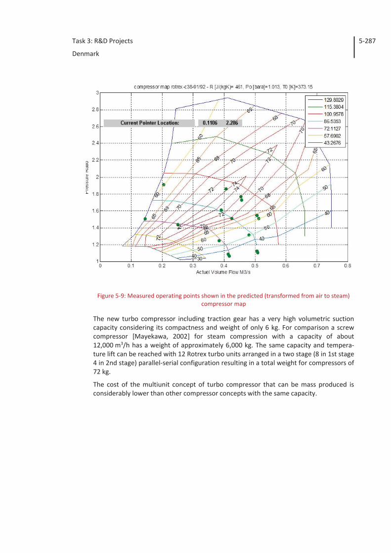
Task 3: R&D Projects
Denmark
5-287
Figure 5-9: Measured operating points shown in the predicted (transformed from air to steam) compressor map
The new turbo compressor including traction gear has a very high volumetric suction capacity considering its compactness and weight of only 6 kg. For comparison a screw compressor [Mayekawa, 2002] for steam compression with a capacity of about 12,000 m3/h has a weight of approximately 6,000 kg. The same capacity and tempera-ture lift can be reached with 12 Rotrex turbo units arranged in a two stage (8 in 1st stage 4 in 2nd stage) parallel-serial configuration resulting in a total weight for compressors of 72 kg.
The cost of the multiunit concept of turbo compressor that can be mass produced is considerably lower than other compressor concepts with the same capacity.
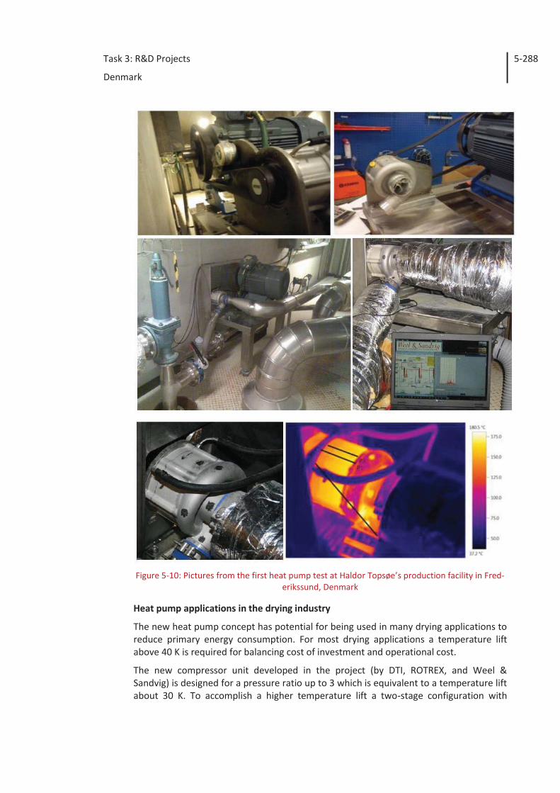
Task 3: R&D Projects
Denmark
5-288
Figure 5-10: Pictures from the first heat pump test at Haldor Topsøe’s production facility in Fred-
erikssund, Denmark
Heat pump applications in the drying industry
The new heat pump concept has potential for being used in many drying applications to reduce primary energy consumption. For most drying applications a temperature lift above 40 K is required for balancing cost of investment and operational cost.
The new compressor unit developed in the project (by DTI, ROTREX, and Weel & Sandvig) is designed for a pressure ratio up to 3 which is equivalent to a temperature lift about 30 K. To accomplish a higher temperature lift a two-stage configuration with
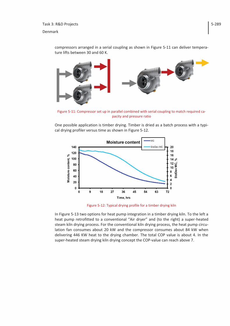
Task 3: R&D Projects
Denmark
5-289
compressors arranged in a serial coupling as shown in Figure 5-11 can deliver tempera-ture lifts between 30 and 60 K.
Figure 5-11: Compressor set up in parallel combined with serial coupling to match required ca-
pacity and pressure ratio
One possible application is timber drying. Timber is dried as a batch process with a typi-cal drying profiler versus time as shown in Figure 5-12.
Figure 5-12: Typical drying profile for a timber drying kiln
In Figure 5-13 two options for heat pump integration in a timber drying kiln. To the left a heat pump retrofitted to a conventional “Air dryer” and (to the right) a super-heated steam kiln drying process. For the conventional kiln drying process, the heat pump circu-lation fan consumes about 20 kW and the compressor consumes about 84 kW when delivering 446 KW heat to the drying chamber. The total COP value is about 4. In the super-heated steam drying kiln drying concept the COP-value can reach above 7.
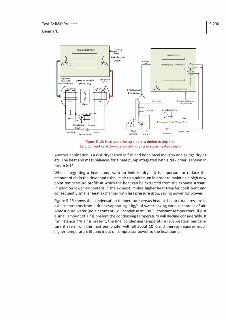
Task 3: R&D Projects
Denmark
5-290
Figure 5-13: Heat pump integrated in a timber drying kiln.
Left: conventional drying and right: drying in super heated steam
Another application is a disk dryer used in fish and bone meal industry and sludge drying etc. The heat and mass balances for a heat pump integrated with a disk dryer is shown in Figure 5-14.
When integrating a heat pump with an indirect dryer it is important to reduce the amount of air in the dryer and exhaust air to a minimum in order to maintain a high dew point temperature profile at which the heat can be extracted from the exhaust stream. In addition lower air content in the exhaust implies higher heat transfer coefficient and consequently smaller heat exchanger with less pressure drop, saving power for blower.
Figure 5-15 shows the condensation temperature versus heat at 1 bara total pressure in exhaust streams from a drier evaporating 1 kg/s of water having various content of air. Almost pure water (no air content) will condense at 100 °C constant temperature. If just a small amount of air is present the condensing temperature will decline considerably. If for instance 7 % air is present, the final condensing temperature (evaporation tempera-ture if seen from the heat pump site) will fall about 10 K and thereby requires much higher temperature lift and input of compressor power to the heat pump.
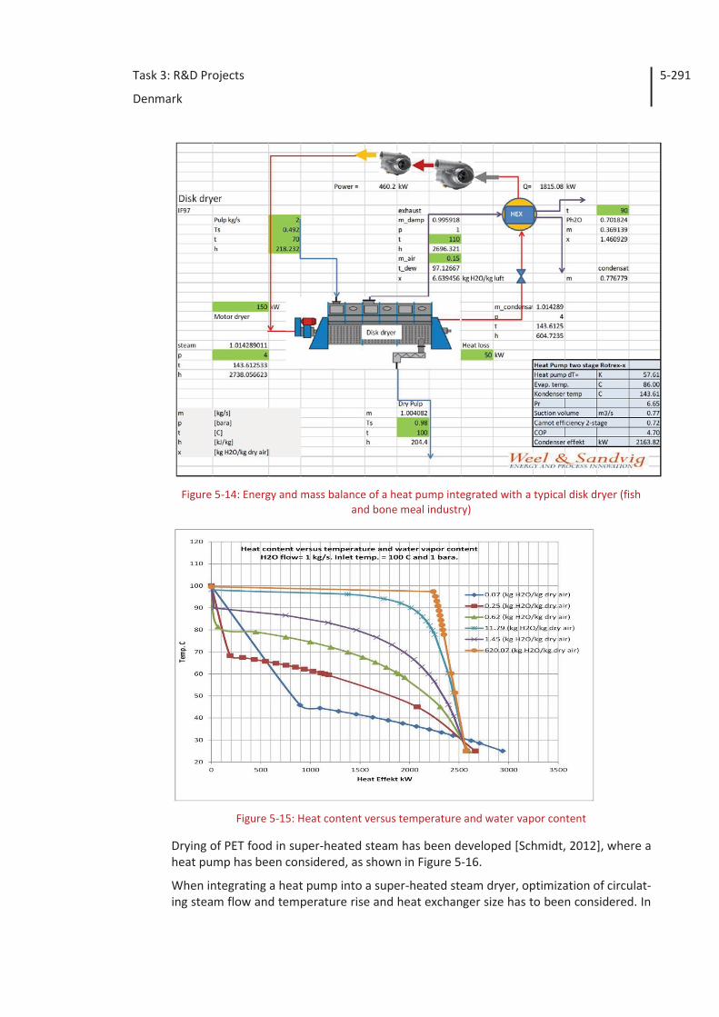
Task 3: R&D Projects
Denmark
5-291
Figure 5-14: Energy and mass balance of a heat pump integrated with a typical disk dryer (fish
and bone meal industry)
Figure 5-15: Heat content versus temperature and water vapor content
Drying of PET food in super-heated steam has been developed [Schmidt, 2012], where a heat pump has been considered, as shown in Figure 5-16.
When integrating a heat pump into a super-heated steam dryer, optimization of circulat-ing steam flow and temperature rise and heat exchanger size has to been considered. In
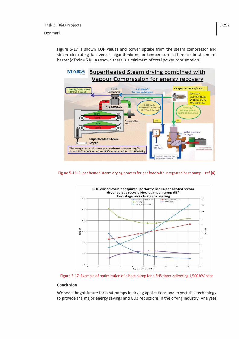
Task 3: R&D Projects
Denmark
5-292
Figure 5-17 is shown COP values and power uptake from the steam compressor and steam circulating fan versus logarithmic mean temperature difference in steam re-heater (dTmin= 5 K). As shown there is a minimum of total power consumption.
Figure 5-16: Super heated steam drying process for pet food with integrated heat pump – ref [4]
Figure 5-17: Example of optimization of a heat pump for a SHS dryer delivering 1,500 kW heat
Conclusion
We see a bright future for heat pumps in drying applications and expect this technology to provide the major energy savings and CO2 reductions in the drying industry. Analyses
Task 3: R&D Projects
Denmark
5-293
have shown that the new turbo-compressor based heat pump concept can be integrated into drying applications and achieve COP-values between 4 and 7.
Mayekawa, 2002 Steam Compressor for Brewery Plant Y. Endo, Mayekawa Mfg. Co. 2002.
Schmidt, 2012 SHS AS A TECHNOLOGY PLATFORM FOR SUSTAINABLE & COM-PETETIV ADVANTAGE, Taastrup 02.11.2012, Siegfried Schmidt, Mars GmbH Europe.
Weel, 2012 Industrial heat pumps for high temperatures, Mogens Weel, Jens Mikkelsen, 2012.
Weel, 2013 The potential for high temperature heat pumps in industrial application, Weel & Sandvig, 2013.
5.3.2 Development of ultra high temperature hybrid heat pump for industrial pro-cesses
Industrial scale heat pumps have until recently been limited to maximum temperatures of 75-80 °C and thereby limiting the application range. During the last years new com-ponents are available and the use of high temperature heat pumps for waste heat re-covery has found its way into the market. A maximal temperature of 100°C is still the limitation for these processes based on the traditional heat pump cycles and fluids. Hy-brid Energy (HE), which is a partner in this project, has reinvented a heat pump process called “the hybrid process” where the absorption and compression cycles are combined. Because of this combination it is possible to reach temperatures of 110° C with standard industrial refrigeration components. This can be done with very high efficiencies. There are currently 6 hybrid plants running in the market with more than 50,000 running hours. The process has proven to be reliable and it is possible to reach the estimated values of COP. During the EUDP project “Utilization of low grade waste heat by means of high temperature heat pumps” the Danish company Innotek was introduced to HE and the hybrid process, and has signed an agreement with HE concerning cost optimization and representative for the Danish market. The interest in Denmark has grown tremen-dous due to this.
The aim of the project is to increase the operating limits of the hybrid process by using the new standard components that are approved to higher pressures. By using new components the maximum temperatures can be as high as 180-250 °C. This will open new markets in the food and process industry for utilizing heat pumps to recover waste energy at a lower temperature level and bring the energy back into processes at a higher temperature level. Nearly 100 % of these processes are today heated using fossil fuels.
The project will demonstrate that it is possible to develop an efficient and reliable heat pump process for high temperatures above 180-250 °C.
The project consists of three parts
1) Theoretical and practical investigation of the hybrid heat pump process for ul-tra-high temperatures
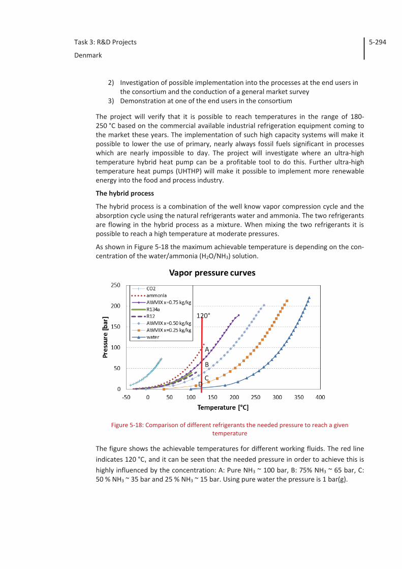
Task 3: R&D Projects
Denmark
5-294
2) Investigation of possible implementation into the processes at the end users in the consortium and the conduction of a general market survey
3) Demonstration at one of the end users in the consortium
The project will verify that it is possible to reach temperatures in the range of 180-250 °C based on the commercial available industrial refrigeration equipment coming to the market these years. The implementation of such high capacity systems will make it possible to lower the use of primary, nearly always fossil fuels significant in processes which are nearly impossible to day. The project will investigate where an ultra-high temperature hybrid heat pump can be a profitable tool to do this. Further ultra-high temperature heat pumps (UHTHP) will make it possible to implement more renewable energy into the food and process industry.
The hybrid process
The hybrid process is a combination of the well know vapor compression cycle and the absorption cycle using the natural refrigerants water and ammonia. The two refrigerants are flowing in the hybrid process as a mixture. When mixing the two refrigerants it is possible to reach a high temperature at moderate pressures.
As shown in Figure 5-18 the maximum achievable temperature is depending on the con-centration of the water/ammonia (H2O/NH3) solution.
Figure 5-18: Comparison of different refrigerants the needed pressure to reach a given
temperature
The figure shows the achievable temperatures for different working fluids. The red line indicates 120 °C, and it can be seen that the needed pressure in order to achieve this is highly influenced by the concentration: A: Pure NH3 ~ 100 bar, B: 75% NH3 ~ 65 bar, C: 50 % NH3 ~ 35 bar and 25 % NH3 ~ 15 bar. Using pure water the pressure is 1 bar(g).
120°
A B C
D
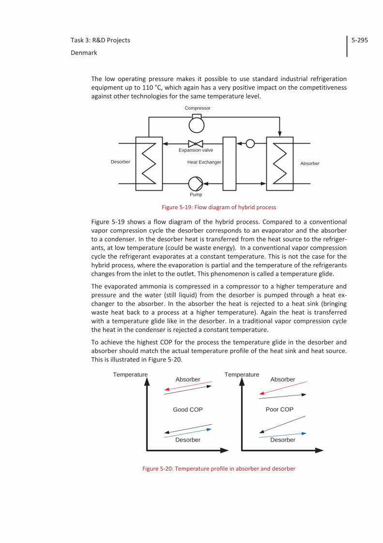
Task 3: R&D Projects
Denmark
5-295
The low operating pressure makes it possible to use standard industrial refrigeration equipment up to 110 °C, which again has a very positive impact on the competitiveness against other technologies for the same temperature level.
Compressor
Expansion valve
Pump
Desorber AbsorberHeat Exchanger
Figure 5-19: Flow diagram of hybrid process
Figure 5-19 shows a flow diagram of the hybrid process. Compared to a conventional vapor compression cycle the desorber corresponds to an evaporator and the absorber to a condenser. In the desorber heat is transferred from the heat source to the refriger-ants, at low temperature (could be waste energy). In a conventional vapor compression cycle the refrigerant evaporates at a constant temperature. This is not the case for the hybrid process, where the evaporation is partial and the temperature of the refrigerants changes from the inlet to the outlet. This phenomenon is called a temperature glide.
The evaporated ammonia is compressed in a compressor to a higher temperature and pressure and the water (still liquid) from the desorber is pumped through a heat ex-changer to the absorber. In the absorber the heat is rejected to a heat sink (bringing waste heat back to a process at a higher temperature). Again the heat is transferred with a temperature glide like in the desorber. In a traditional vapor compression cycle the heat in the condenser is rejected a constant temperature.
To achieve the highest COP for the process the temperature glide in the desorber and absorber should match the actual temperature profile of the heat sink and heat source. This is illustrated in Figure 5-20.
Absorber
Desorber
TemperatureAbsorber
Desorber
Good COP Poor COP
Temperature
Figure 5-20: Temperature profile in absorber and desorber
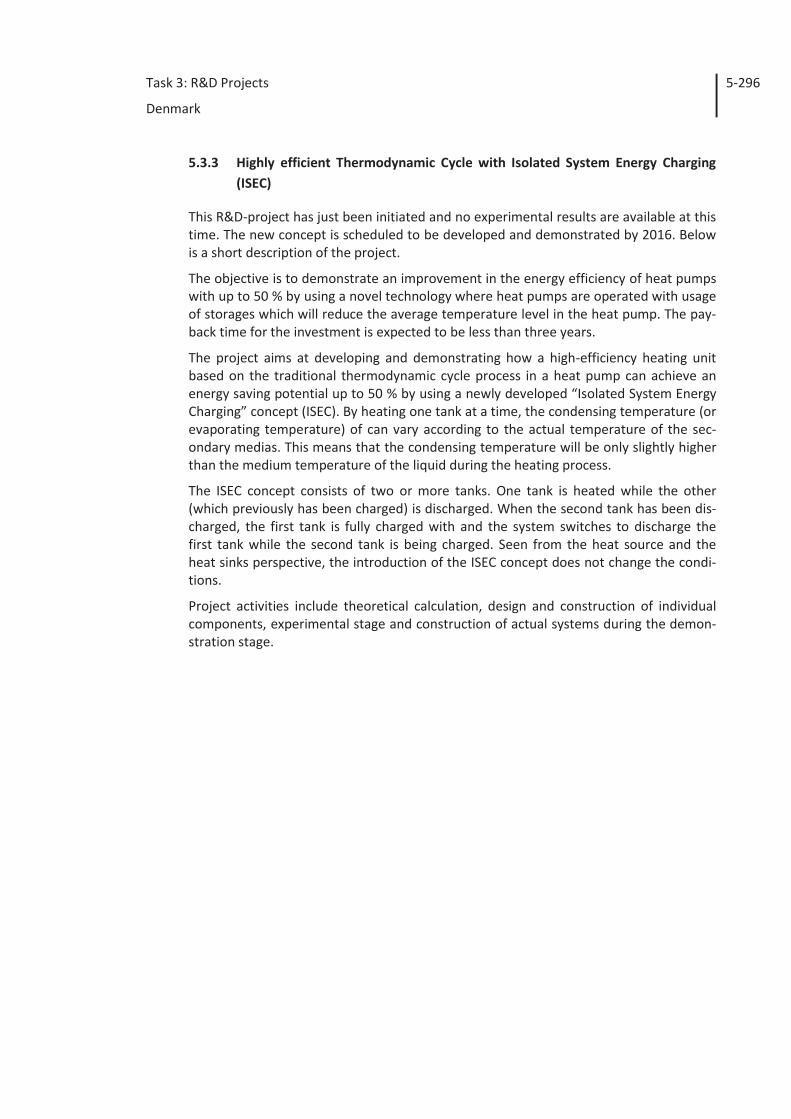
Task 3: R&D Projects
Denmark
5-296
5.3.3 Highly efficient Thermodynamic Cycle with Isolated System Energy Charging (ISEC)
This R&D-project has just been initiated and no experimental results are available at this time. The new concept is scheduled to be developed and demonstrated by 2016. Below is a short description of the project.
The objective is to demonstrate an improvement in the energy efficiency of heat pumps with up to 50 % by using a novel technology where heat pumps are operated with usage of storages which will reduce the average temperature level in the heat pump. The pay-back time for the investment is expected to be less than three years.
The project aims at developing and demonstrating how a high-efficiency heating unit based on the traditional thermodynamic cycle process in a heat pump can achieve an energy saving potential up to 50 % by using a newly developed “Isolated System Energy Charging” concept (ISEC). By heating one tank at a time, the condensing temperature (or evaporating temperature) of can vary according to the actual temperature of the sec-ondary medias. This means that the condensing temperature will be only slightly higher than the medium temperature of the liquid during the heating process.
The ISEC concept consists of two or more tanks. One tank is heated while the other (which previously has been charged) is discharged. When the second tank has been dis-charged, the first tank is fully charged with and the system switches to discharge the first tank while the second tank is being charged. Seen from the heat source and the heat sinks perspective, the introduction of the ISEC concept does not change the condi-tions.
Project activities include theoretical calculation, design and construction of individual components, experimental stage and construction of actual systems during the demon-stration stage.
Task 3: R&D Projects
Denmark
5-297
5.4 Economy and other incentives
As mentioned elsewhere in this report, electricity is 2.5 to 3.5 times more expensive than traditional fuels for boilers, thus requiring a COP for heat pumps in this area or higher in order to be competitive in industrial applications. The initial cost of heat pumps compared to traditional heating plants is also several times higher, meaning that only heat pumps with very high COP values and many operating hours will be profitable. Because of this the most immediate applications are processes with small temperature lifts, a lot of operating hours and a steady demand meaning less complex (expensive) systems.
Although payback periods from reduced energy consumption are longer than desired in most cases, there could be other drivers. Cooperative energy policies such as reduced consumption, CO2-foot print and so on could be met by utilizing heat pumps.
In Denmark energy consumers and providers are required to reduce energy consump-tion by a certain amount each year. This requirement can be met either by reducing one’s own energy consumption, or by buying an excess reduction from somewhere else. E.g. three companies are each required to reduce their energy consumption by 5 MWh a year. If one of the companies finds a way to reduce energy consumption in that compa-ny by 15 MWh and the others don’t reduce consumption, it is allowed for the first com-pany to “cover” for the other two companies by splitting the excess reduction. In praxis the energy reductions (called energy savings) are traded between companies, suppliers and advisors throughout each year. The price for each MWh of “energy savings” varies depending on the buyer, availability and expectations to the market. One MWh of “en-ergy savings” typically holds a value of between 50 and 65 Euros. For heat pumps with many operating hours (> 6,000/yr), “energy savings” will typically cover half of the in-vestment costs meaning that this “subsidy” is essential for heat pumps in industrial ap-plications.
“Energy savings” has no value in district heating plants as these are not part of this sys-tem. Energy consumption for residential heating is taxed and heat pumps have an ad-vantage as tax per heat unit is considerable lower using heat pumps than other fossil fuels. This means that utilization of heat pumps in district heating systems is possible with short pay back periods as well.
Task 3: R&D Projects
France
6-298
6 France
6.1 Introduction
Europe is now committed on its energy policy for 2020 and further. Among other objec-tives, the European Union shall reduce its own CO2 emissions and energy consumption and increase the proportion of renewable energies in its energy mix by at least 20%. Supplier obligations and white certificates were established in France in order to con-tribute to these energy-efficiency goals. Energy savings in the industrial sector are eligi-ble for white certificates, as well as are the residential and commercial sectors.
Energy consumption in French industry represents 450 TWh/year. About 75% of the final energy use is for thermal purposes (furnaces, reactors, boilers, dryers etc.). The major part of that heat comes from the combustion of fossil fuels generating large CO2 emis-sions. Some studies estimate that around 30% of the final energy used for thermal pur-poses is wasted through losses In the industrial sector, only few measures can be re-warded by white certificates in France. Most of them are obtained through boiler econ-omizers and variable speed drives (VSD). Indeed, these two measures have high EE po-tential and are quite simple to implement on site. On the opposite, energy savings of more complex projects can hardly be estimated by standardized ex-ante methods and the evaluation procedure of non-standardized measures is quite slow. As a conse-quence, complex actions such as heat recovery on industrial processes can hardly be rewarded for the moment. However, in order to achieve energy-efficiency and CO2 goals, actions of saving, recovering and utilizing the heat should be developed and recognized as eligible for white certificates.
The main industrial heat needs range from 60 to 140 °C and they represent about 30 TWh/year. At these temperature levels, many opportunities for heat Pump technolo-gy exist, and allow recovering low temperature heat to produce high temperature heat.
Some studies estimate that it is in theory possible to recover in flue gases between 10 % and 25% of the fuel used by thermal high temperature equipments such as boilers, fur-nace or dryers, which means approximately 35-85 TWh/yr for France. However, this whole potential is not entirely economically accessible. For example, some flue gases can be corrosive so that it is expensive to install a heat exchanger with a resistant mate-rial. In addition, compared to quality of products and productivity, energy savings are not a major criterion for investments in industry. EDF experienced that pure EE invest-ments (not dedicated to the production) must generally have a payback time lower than 3 years to be accepted. Due to that strict criterion, some investments will not be “judged” as cost-effective by certain industrials so that a part of the whole potential will not be reached.
Heat pumps (HP) often require important investments. Hence, this technology will spread first and principally to sectors with the shortest payback time.
In the 80’s in France, developments of high temperature heat pump started to emerge. Due to the low price of energy and high investment, it was difficult to find a good return on investment, gas boilers were preferred. Since a few years, there is a renewed interest for heat pumps. Recent developments have been made to develop industrial
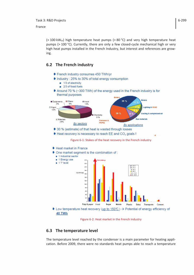
Task 3: R&D Projects
France
6-299
(> 100 kWth) high temperature heat pumps (> 80 °C) and very high temperature heat pumps (> 100 °C). Currently, there are only a few closed-cycle mechanical high or very high heat pumps installed in the French Industry, but interest and references are grow-ing.
6.2 The French industry
Figure 6-1: Stakes of the heat recovery in the French industry
Figure 6-2: Heat market in the French industry
6.3 The temperature level
The temperature level reached by the condenser is a main parameter for heating appli-cation. Before 2009, there were no standards heat pumps able to reach a temperature
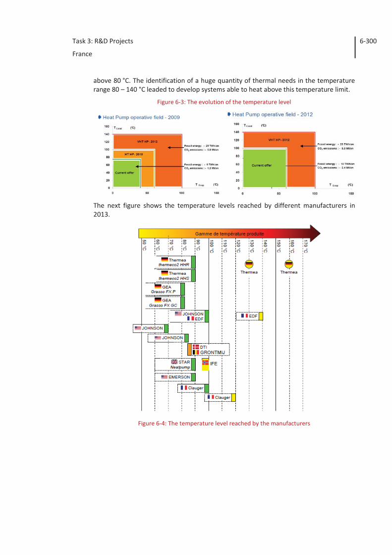
Task 3: R&D Projects
France
6-300
above 80 °C. The identification of a huge quantity of thermal needs in the temperature range 80 – 140 °C leaded to develop systems able to heat above this temperature limit.
Figure 6-3: The evolution of the temperature level
The next figure shows the temperature levels reached by different manufacturers in 2013.
Figure 6-4: The temperature level reached by the manufacturers
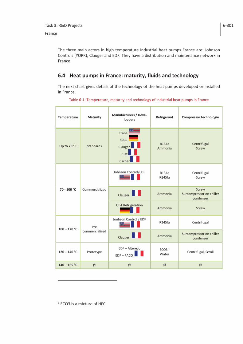
Task 3: R&D Projects
France
6-301
The three main actors in high temperature industrial heat pumps France are: Johnson Controls (YORK), Clauger and EDF. They have a distribution and maintenance network in France.
6.4 Heat pumps in France: maturity, fluids and technology
The next chart gives details of the technology of the heat pumps developed or installed in France.
Table 6-1: Temperature, maturity and technology of industrial heat pumps in France
Temperature Maturity Manufacturers / Deve-
loppers Refrigerant Compressor technologie
Up to 70 °C Standards
Trane
GEA
Clauger
Ciat
Carrier
R134a Ammonia
Centrifugal Screw
70 - 100 °C Commercialized
Johnson Control/EDF
R134a R245fa
Centrifugal Screw
Clauger Ammonia Screw
Surcompressor on chiller condenser
GEA Refrigeration
Ammonia Screw
100 – 120 °C Pre
commercialized
Jonhson Control / EDF
R245fa Centrifugal
Clauger Ammonia Surcompressor on chiller condenser
120 – 140 °C Prototype EDF – Altereco
EDF – PACO
ECO3 1 Water Centrifugal, Scroll
140 – 165 °C Ø Ø Ø Ø
1 ECO3 is a mixture of HFC
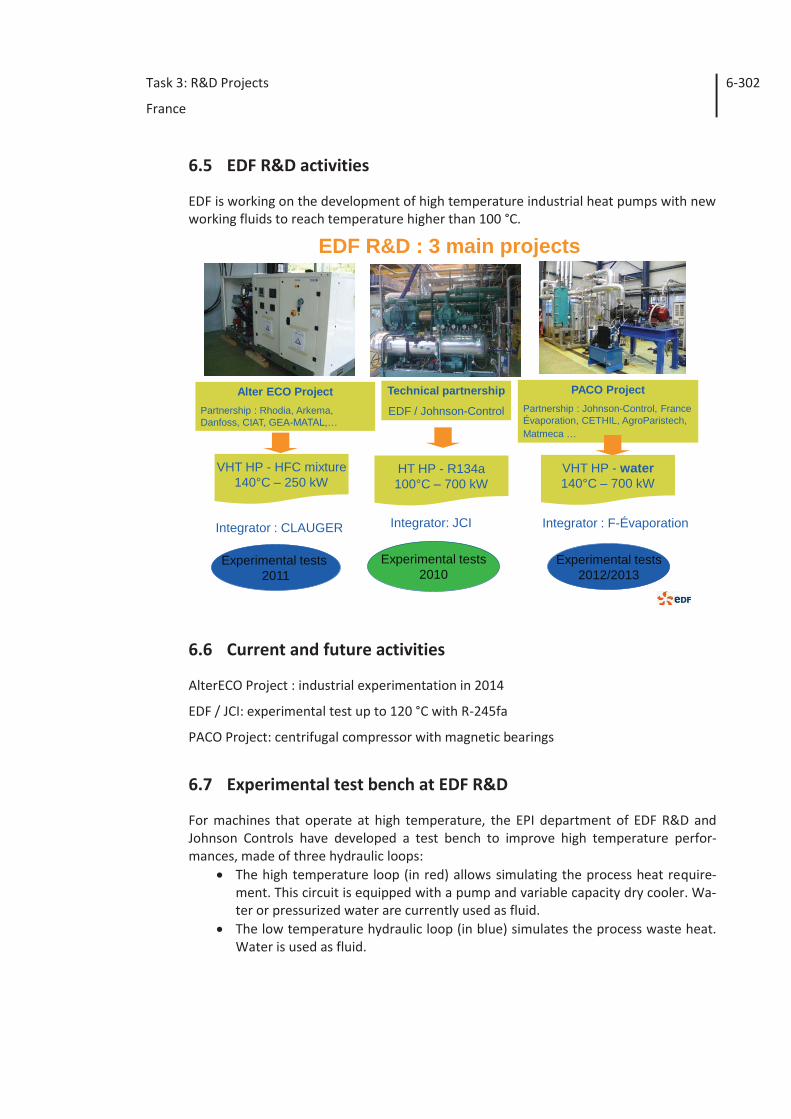
Task 3: R&D Projects
France
6-302
6.5 EDF R&D activities
EDF is working on the development of high temperature industrial heat pumps with new working fluids to reach temperature higher than 100 °C.
EDF R&D : 3 main projects
Alter ECO ProjectPartnership : Rhodia, Arkema, Danfoss, CIAT, GEA-MATAL,…
VHT HP - HFC mixture140°C – 250 kW
Integrator : CLAUGER
Experimental tests 2011
Technical partnership
EDF / Johnson-Control
HT HP - R134a100°C – 700 kW
Integrator: JCI
Experimental tests2010
Integrator : F-Évaporation
PACO ProjectPartnership : Johnson-Control, France Évaporation, CETHIL, AgroParistech, Matmeca …
VHT HP - water140°C – 700 kW
Experimental tests2012/2013
6.6 Current and future activities
AlterECO Project : industrial experimentation in 2014
EDF / JCI: experimental test up to 120 °C with R-245fa
PACO Project: centrifugal compressor with magnetic bearings
6.7 Experimental test bench at EDF R&D
For machines that operate at high temperature, the EPI department of EDF R&D and Johnson Controls have developed a test bench to improve high temperature perfor-mances, made of three hydraulic loops:
The high temperature loop (in red) allows simulating the process heat require-ment. This circuit is equipped with a pump and variable capacity dry cooler. Wa-ter or pressurized water are currently used as fluid.
The low temperature hydraulic loop (in blue) simulates the process waste heat. Water is used as fluid.
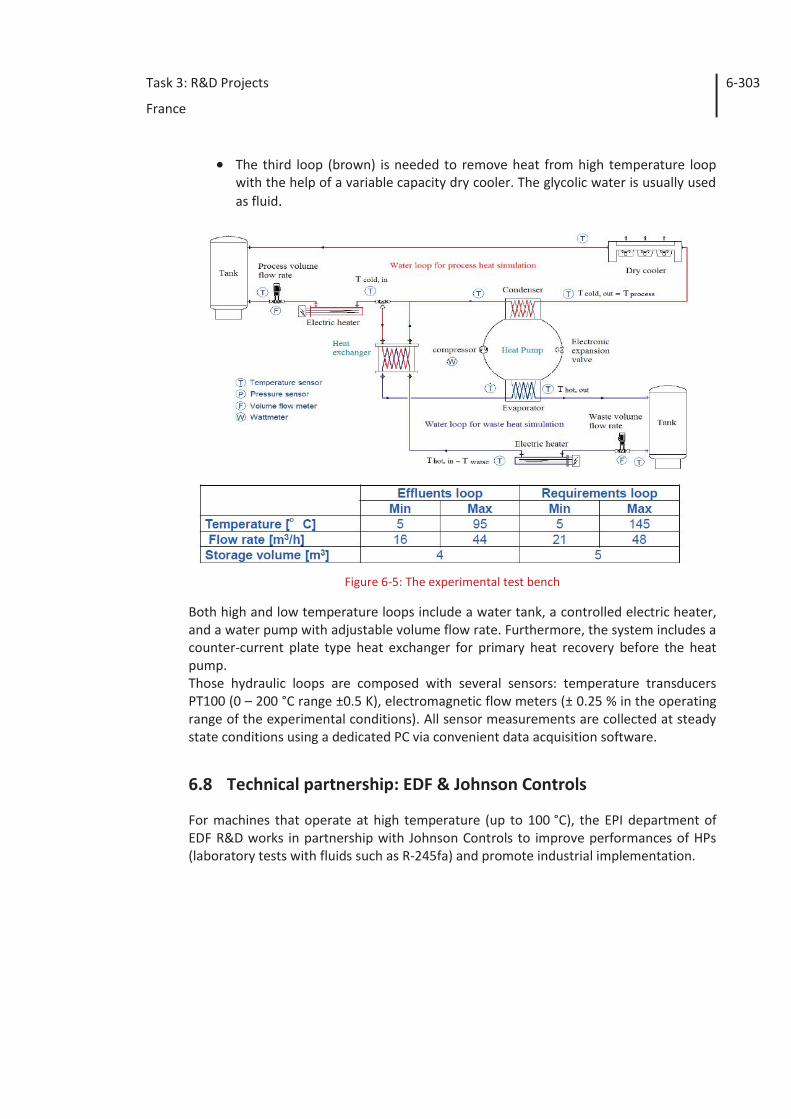
Task 3: R&D Projects
France
6-303
The third loop (brown) is needed to remove heat from high temperature loop with the help of a variable capacity dry cooler. The glycolic water is usually used as fluid.
Figure 6-5: The experimental test bench
Both high and low temperature loops include a water tank, a controlled electric heater, and a water pump with adjustable volume flow rate. Furthermore, the system includes a counter-current plate type heat exchanger for primary heat recovery before the heat pump. Those hydraulic loops are composed with several sensors: temperature transducers PT100 (0 – 200 °C range ±0.5 K), electromagnetic flow meters (± 0.25 % in the operating range of the experimental conditions). All sensor measurements are collected at steady state conditions using a dedicated PC via convenient data acquisition software.
6.8 Technical partnership: EDF & Johnson Controls
For machines that operate at high temperature (up to 100 °C), the EPI department of EDF R&D works in partnership with Johnson Controls to improve performances of HPs (laboratory tests with fluids such as R-245fa) and promote industrial implementation.

Task 3: R&D Projects
France
6-304
6.8.1 Description of the heat pump
Figure 6-6: The JCI / EDF heat pump
The double screw compressor was replaced with a centrifugal compressor.
Figure 6-7: Schematic of the JCI / EDF heat pump system
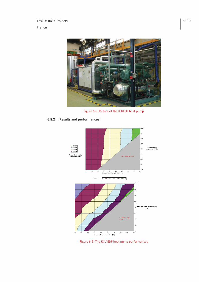
Task 3: R&D Projects
France
6-305
Figure 6-8: Picture of the JCI/EDF heat pump
6.8.2 Results and performances
Figure 6-9: The JCI / EDF heat pump performances
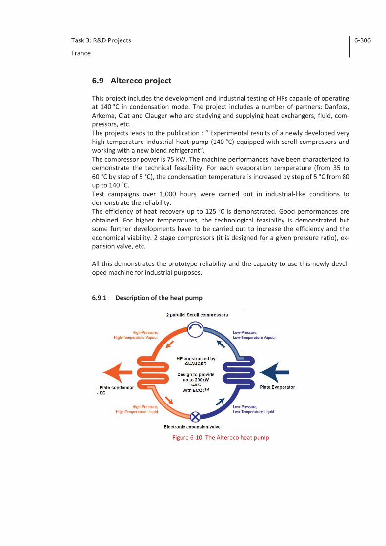
Task 3: R&D Projects
France
6-306
6.9 Altereco project
This project includes the development and industrial testing of HPs capable of operating at 140 °C in condensation mode. The project includes a number of partners: Danfoss, Arkema, Ciat and Clauger who are studying and supplying heat exchangers, fluid, com-pressors, etc. The projects leads to the publication : “ Experimental results of a newly developed very high temperature industrial heat pump (140 °C) equipped with scroll compressors and working with a new blend refrigerant”. The compressor power is 75 kW. The machine performances have been characterized to demonstrate the technical feasibility. For each evaporation temperature (from 35 to 60 °C by step of 5 °C), the condensation temperature is increased by step of 5 °C from 80 up to 140 °C. Test campaigns over 1,000 hours were carried out in industrial-like conditions to demonstrate the reliability. The efficiency of heat recovery up to 125 °C is demonstrated. Good performances are obtained. For higher temperatures, the technological feasibility is demonstrated but some further developments have to be carried out to increase the efficiency and the economical viability: 2 stage compressors (it is designed for a given pressure ratio), ex-pansion valve, etc. All this demonstrates the prototype reliability and the capacity to use this newly devel-oped machine for industrial purposes.
6.9.1 Description of the heat pump
Figure 6-10: The Altereco heat pump
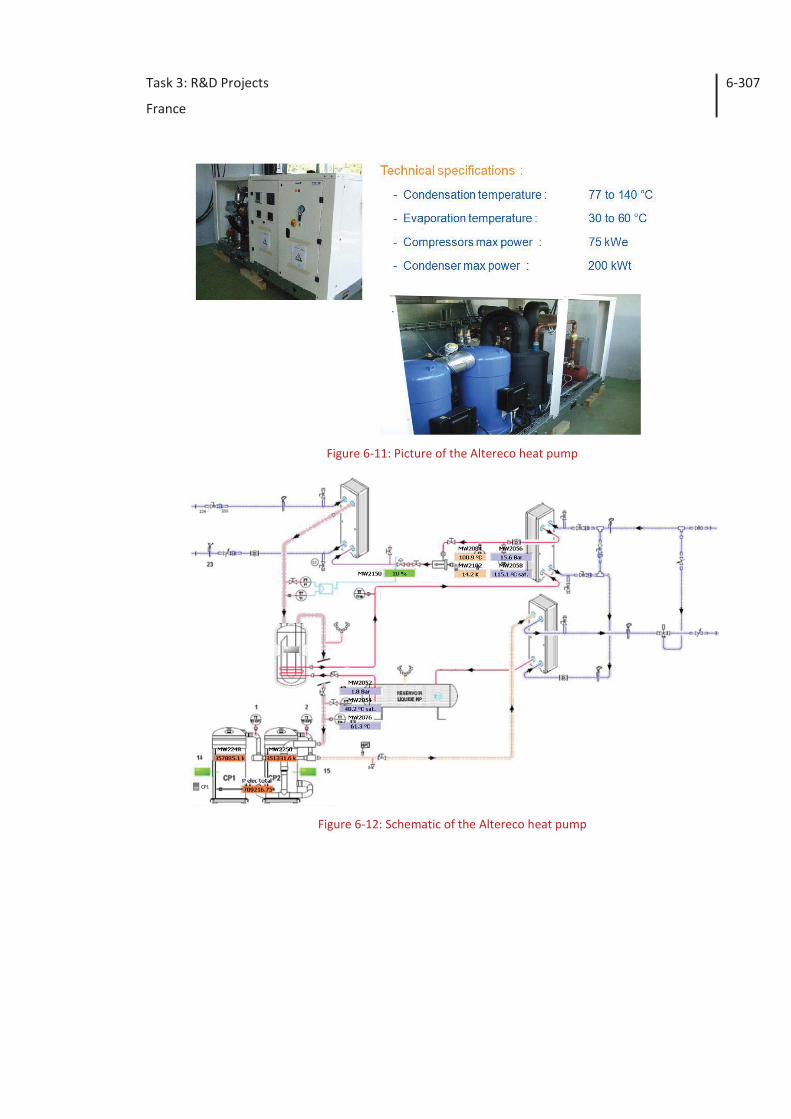
Task 3: R&D Projects
France
6-307
Figure 6-11: Picture of the Altereco heat pump
Figure 6-12: Schematic of the Altereco heat pump
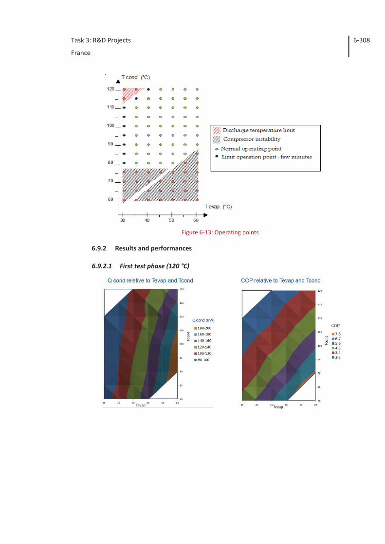
Task 3: R&D Projects
France
6-308
Figure 6-13: Operating points
6.9.2 Results and performances
6.9.2.1 First test phase (120 °C)
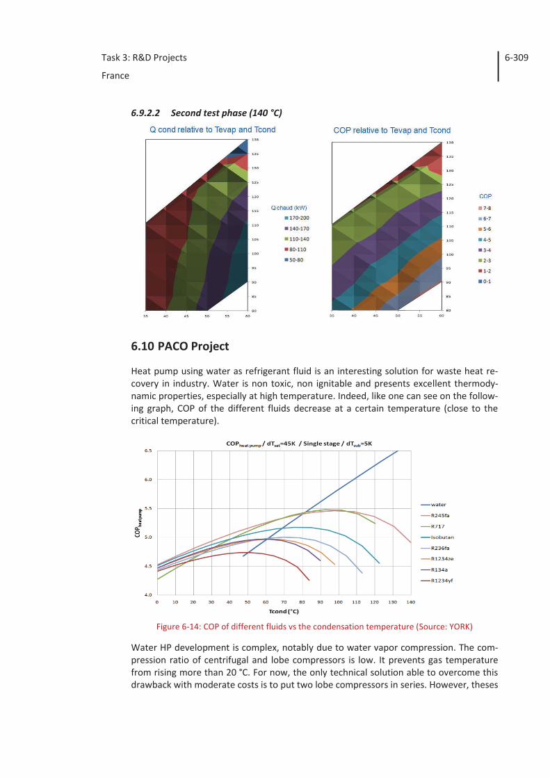
Task 3: R&D Projects
France
6-309
6.9.2.2 Second test phase (140 °C)
6.10 PACO Project
Heat pump using water as refrigerant fluid is an interesting solution for waste heat re-covery in industry. Water is non toxic, non ignitable and presents excellent thermody-namic properties, especially at high temperature. Indeed, like one can see on the follow-ing graph, COP of the different fluids decrease at a certain temperature (close to the critical temperature).
Figure 6-14: COP of different fluids vs the condensation temperature (Source: YORK)
Water HP development is complex, notably due to water vapor compression. The com-pression ratio of centrifugal and lobe compressors is low. It prevents gas temperature from rising more than 20 °C. For now, the only technical solution able to overcome this drawback with moderate costs is to put two lobe compressors in series. However, theses
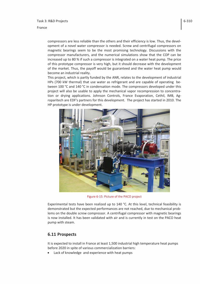
Task 3: R&D Projects
France
6-310
compressors are less reliable than the others and their efficiency is low. Thus, the devel-opment of a novel water compressor is needed. Screw and centrifugal compressors on magnetic bearings seem to be the most promising technology. Discussions with the compressor manufacturers, and the numerical simulations show that the COP can be increased up to 80 % if such a compressor is integrated on a water heat pump. The price of this prototype compressor is very high, but it should decrease with the development of the market. Thus, the payoff would be guaranteed and the water heat pump would become an industrial reality. This project, which is partly funded by the ANR, relates to the development of industrial HPs (700 kW thermal) that use water as refrigerant and are capable of operating be-tween 100 °C and 140 °C in condensation mode. The compressors developed under this project will also be usable to apply the mechanical vapor recompression to concentra-tion or drying applications. Johnson Controls, France Evaporation, Cethil, IMB, Ag-roparitech are EDF's partners for this development. The project has started in 2010. The HP prototype is under development.
Figure 6-15: Picture of the PACO project
Experimental tests have been realized up to 140 °C. At this level, technical feasibility is demonstrated but the expected performances are not reached, due to mechanical prob-lems on the double screw compressor. A centrifugal compressor with magnetic bearings is now installed. It has been validated with air and is currently in test on the PACO heat pump with steam.
6.11 Prospects
It is expected to install in France at least 1,500 industrial high temperature heat pumps before 2020 in spite of various commercialization barriers: Lack of knowledge and experience with heat pumps
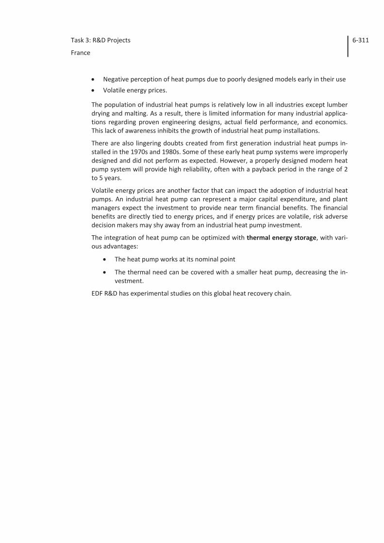
Task 3: R&D Projects
France
6-311
Negative perception of heat pumps due to poorly designed models early in their use
Volatile energy prices.
The population of industrial heat pumps is relatively low in all industries except lumber drying and malting. As a result, there is limited information for many industrial applica-tions regarding proven engineering designs, actual field performance, and economics. This lack of awareness inhibits the growth of industrial heat pump installations.
There are also lingering doubts created from first generation industrial heat pumps in-stalled in the 1970s and 1980s. Some of these early heat pump systems were improperly designed and did not perform as expected. However, a properly designed modern heat pump system will provide high reliability, often with a payback period in the range of 2 to 5 years.
Volatile energy prices are another factor that can impact the adoption of industrial heat pumps. An industrial heat pump can represent a major capital expenditure, and plant managers expect the investment to provide near term financial benefits. The financial benefits are directly tied to energy prices, and if energy prices are volatile, risk adverse decision makers may shy away from an industrial heat pump investment.
The integration of heat pump can be optimized with thermal energy storage, with vari-ous advantages:
The heat pump works at its nominal point
The thermal need can be covered with a smaller heat pump, decreasing the in-vestment.
EDF R&D has experimental studies on this global heat recovery chain.
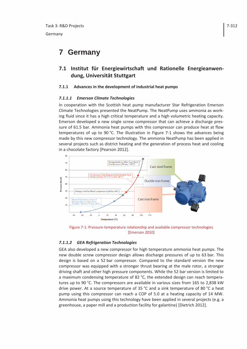
Task 3: R&D Projects
Germany
7-312
7 Germany
7.1 Institut für Energiewirtschaft und Rationelle Energieanwen-dung, Universität Stuttgart
7.1.1 Advances in the development of industrial heat pumps
7.1.1.1 Emerson Climate Technologies In cooperation with the Scottish heat pump manufacturer Star Refrigeration Emerson Climate Technologies presented the NeatPump. The NeatPump uses ammonia as work-ing fluid since it has a high critical temperature and a high volumetric heating capacity. Emerson developed a new single screw compressor that can achieve a discharge pres-sure of 61.5 bar. Ammonia heat pumps with this compressor can produce heat at flow temperatures of up to 90 °C. The illustration in Figure 7-1 shows the advances being made by this new compressor technology. The ammonia NeatPump has been applied in several projects such as district heating and the generation of process heat and cooling in a chocolate factory [Pearson 2012].
Figure 7-1: Pressure-temperature relationship and available compressor technologies
[Emerson 2010]
7.1.1.2 GEA Refrigeration Technologies GEA also developed a new compressor for high temperature ammonia heat pumps. The new double screw compressor design allows discharge pressures of up to 63 bar. This design is based on a 52 bar compressor. Compared to the standard version the new compressor was equipped with a stronger thrust bearing at the male rotor, a stronger driving shaft and other high pressure components. While the 52 bar version is limited to a maximum condensing temperature of 82 °C, the extended design can reach tempera-tures up to 90 °C. The compressors are available in various sizes from 165 to 2,838 kW drive power. At a source temperature of 35 °C and a sink temperature of 80 °C a heat pump using this compressor can reach a COP of 5.0 at a heating capacity of 14 MW. Ammonia heat pumps using this technology have been applied in several projects (e.g. a greenhouse, a paper mill and a production facility for galantine) [Dietrich 2012].
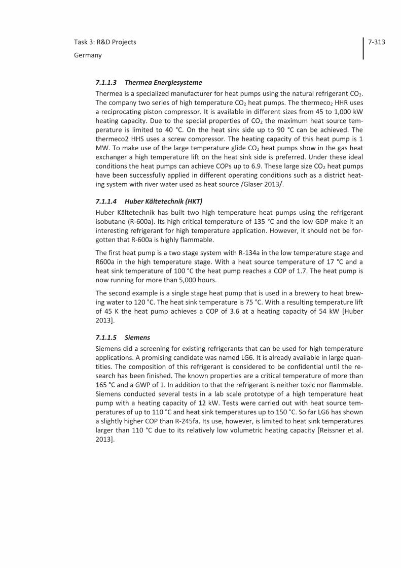
Task 3: R&D Projects
Germany
7-313
7.1.1.3 Thermea Energiesysteme Thermea is a specialized manufacturer for heat pumps using the natural refrigerant CO2. The company two series of high temperature CO2 heat pumps. The thermeco2 HHR uses a reciprocating piston compressor. It is available in different sizes from 45 to 1,000 kW heating capacity. Due to the special properties of CO2 the maximum heat source tem-perature is limited to 40 °C. On the heat sink side up to 90 °C can be achieved. The thermeco2 HHS uses a screw compressor. The heating capacity of this heat pump is 1 MW. To make use of the large temperature glide CO2 heat pumps show in the gas heat exchanger a high temperature lift on the heat sink side is preferred. Under these ideal conditions the heat pumps can achieve COPs up to 6.9. These large size CO2 heat pumps have been successfully applied in different operating conditions such as a district heat-ing system with river water used as heat source /Glaser 2013/.
7.1.1.4 Huber Kältetechnik (HKT) Huber Kältetechnik has built two high temperature heat pumps using the refrigerant isobutane (R-600a). Its high critical temperature of 135 °C and the low GDP make it an interesting refrigerant for high temperature application. However, it should not be for-gotten that R-600a is highly flammable.
The first heat pump is a two stage system with R-134a in the low temperature stage and R600a in the high temperature stage. With a heat source temperature of 17 °C and a heat sink temperature of 100 °C the heat pump reaches a COP of 1.7. The heat pump is now running for more than 5,000 hours.
The second example is a single stage heat pump that is used in a brewery to heat brew-ing water to 120 °C. The heat sink temperature is 75 °C. With a resulting temperature lift of 45 K the heat pump achieves a COP of 3.6 at a heating capacity of 54 kW [Huber 2013].
7.1.1.5 Siemens Siemens did a screening for existing refrigerants that can be used for high temperature applications. A promising candidate was named LG6. It is already available in large quan-tities. The composition of this refrigerant is considered to be confidential until the re-search has been finished. The known properties are a critical temperature of more than 165 °C and a GWP of 1. In addition to that the refrigerant is neither toxic nor flammable. Siemens conducted several tests in a lab scale prototype of a high temperature heat pump with a heating capacity of 12 kW. Tests were carried out with heat source tem-peratures of up to 110 °C and heat sink temperatures up to 150 °C. So far LG6 has shown a slightly higher COP than R-245fa. Its use, however, is limited to heat sink temperatures larger than 110 °C due to its relatively low volumetric heating capacity [Reissner et al. 2013].
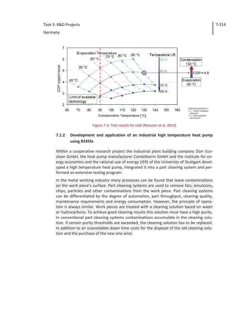
Task 3: R&D Projects
Germany
7-314
Figure 7-2: Test results for LG6 [Reissner et al. 2013]
7.1.2 Development and application of an industrial high temperature heat pump using R245fa
Within a cooperative research project the industrial plant building company Dürr Eco-clean GmbH, the heat pump manufacturer Combitherm GmbH and the institute for en-ergy economics and the rational use of energy (IER) of the University of Stuttgart devel-oped a high temperature heat pump, integrated it into a part cleaning system and per-formed an extensive testing program.
In the metal working industry many processes can be found that leave contaminations on the work piece’s surface. Part cleaning systems are used to remove fats, emulsions, chips, particles and other contaminations from the work piece. Part cleaning systems can be differentiated by the degree of automation, part throughput, cleaning quality, maintenance requirements and energy consumption. However, the principle of opera-tion is always similar. Work pieces are treated with a cleaning solution based on water or hydrocarbons. To achieve good cleaning results this solution must have a high purity. In conventional part cleaning systems contaminations accumulate in the cleaning solu-tion. If certain purity thresholds are exceeded, the cleaning solution has to be replaced. In addition to an unavoidable down time costs for the disposal of the old cleaning solu-tion and the purchase of the new one arise.
Task 3: R&D Projects
Germany
7-315
Figure 7-3: Scheme of the part cleaning system EcoCMax
Dürr Ecoclean reduced the need for regular exchanges of the cleaning solution by inte-grating a bath preparation unit into their part cleaning systems. Figure 7-3 shows a sim-plified scheme of the part cleaning system with the integrated bath preparation. In the bath preparation module heat is applied at 100 °C to evaporate the water based clean-ing solution. The heat needed for this process is entirely generated by electric heaters. Contaminations that boil at higher temperatures such as oils and fats remain in the evaporator. They have to be disposed periodically. The heat content of the evaporated cleaning solution is used to heat three tanks that hold the cleaning solution at a 60 to 70 °C. In this way most of the heat can be recovered. However, if the bath preparation is operated at full load it generates more waste heat than can be recovered. In the heat controlled operation mode the bath preparation can only prepare 5 l of cleaning solu-tion per hour. At full load up to 50 l/h can be prepared with 36 kW heat input. In this case an external cooling system needs to absorb the heat surplus. To recover this waste heat and thereby to allow the bath preparation to operate at full load without the need of external cooling a heat pump was taken into account.
Other companies took similar approaches to increase the usage time of the cleaning solution and to improve the energy efficiency of their part cleaning systems. They offer central bath preparation units that recover waste heat using mechanical vapor recom-pression (MVR). Those systems are of much larger size with treatment capacities of up to 1,500 l/h. The energy input for these systems is 35 Wh/l.
7.1.2.1 Development of the high temperature heat pump In contrast to the competitive stand-alone bath preparation systems, Dürr integrated the bath preparation into the part cleaning system. Therefore operating conditions are much more volatile compared to a stand-alone bath preparation unit. Since a vapor recompression system works best at stationary operating conditions and potentially causes problems in combination with certain cleaning agents, Dürr decided to use a more flexible closed cycle compression heat pump.
To limit heat losses the condenser of the heat pump had to be integrated into the bath preparation unit. Because of the limited construction space, the heat exchanger has to be relatively small, so that a high driving temperature difference of 10 to 15 K is needed. Due to the high condensing temperature of up to 115 °C, conventional refrigerants like R-410A or R-134a could not be used. A screening of available refrigerants resulted in the
Cleaning Chamber
Tank 360 to 70 °C
Bath Preparation100 °C
Tank 260 to 70 °C
Tank 160 to 70 °C
Auxiliary Electircal Heater
cooling
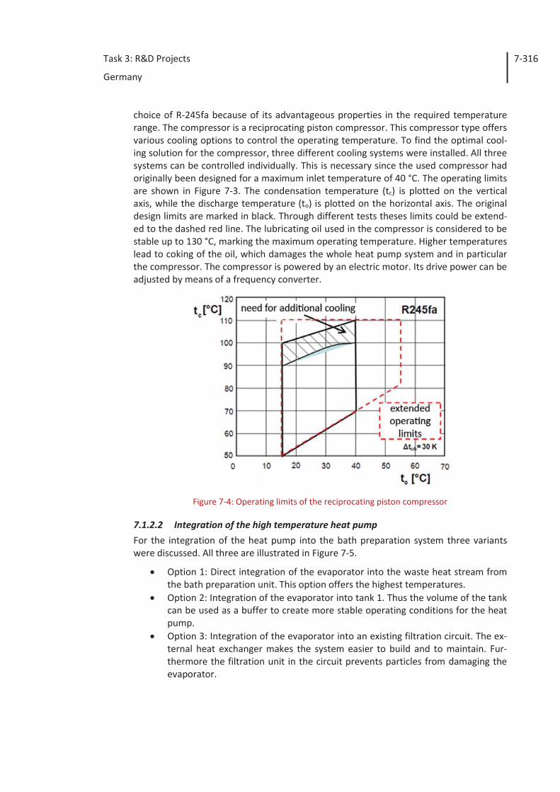
Task 3: R&D Projects
Germany
7-316
choice of R-245fa because of its advantageous properties in the required temperature range. The compressor is a reciprocating piston compressor. This compressor type offers various cooling options to control the operating temperature. To find the optimal cool-ing solution for the compressor, three different cooling systems were installed. All three systems can be controlled individually. This is necessary since the used compressor had originally been designed for a maximum inlet temperature of 40 °C. The operating limits are shown in Figure 7-3. The condensation temperature (tc) is plotted on the vertical axis, while the discharge temperature (to) is plotted on the horizontal axis. The original design limits are marked in black. Through different tests theses limits could be extend-ed to the dashed red line. The lubricating oil used in the compressor is considered to be stable up to 130 °C, marking the maximum operating temperature. Higher temperatures lead to coking of the oil, which damages the whole heat pump system and in particular the compressor. The compressor is powered by an electric motor. Its drive power can be adjusted by means of a frequency converter.
Figure 7-4: Operating limits of the reciprocating piston compressor
7.1.2.2 Integration of the high temperature heat pump For the integration of the heat pump into the bath preparation system three variants were discussed. All three are illustrated in Figure 7-5.
Option 1: Direct integration of the evaporator into the waste heat stream from the bath preparation unit. This option offers the highest temperatures.
Option 2: Integration of the evaporator into tank 1. Thus the volume of the tank can be used as a buffer to create more stable operating conditions for the heat pump.
Option 3: Integration of the evaporator into an existing filtration circuit. The ex-ternal heat exchanger makes the system easier to build and to maintain. Fur-thermore the filtration unit in the circuit prevents particles from damaging the evaporator.
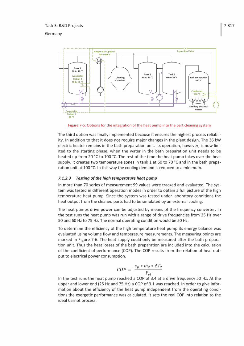
Task 3: R&D Projects
Germany
7-317
Figure 7-5: Options for the integration of the heat pump into the part cleaning system
The third option was finally implemented because it ensures the highest process reliabil-ity. In addition to that it does not require major changes in the plant design. The 36 kW electric heater remains in the bath preparation unit. Its operation, however, is now lim-ited to the starting phase, when the water in the bath preparation unit needs to be heated up from 20 °C to 100 °C. The rest of the time the heat pump takes over the heat supply. It creates two temperature zones in tank 1 at 60 to 70 °C and in the bath prepa-ration unit at 100 °C. In this way the cooling demand is reduced to a minimum.
7.1.2.3 Testing of the high temperature heat pump In more than 70 series of measurement 99 values were tracked and evaluated. The sys-tem was tested in different operation modes in order to obtain a full picture of the high temperature heat pump. Since the system was tested under laboratory conditions the heat output from the cleaned parts had to be simulated by an external cooling.
The heat pumps drive power can be adjusted by means of the frequency converter. In the test runs the heat pump was run with a range of drive frequencies from 25 Hz over 50 and 60 Hz to 75 Hz. The normal operating condition would be 50 Hz.
To determine the efficiency of the high temperature heat pump its energy balance was evaluated using volume flow and temperature measurements. The measuring points are marked in Figure 7-6. The heat supply could only be measured after the bath prepara-tion unit. Thus the heat losses of the bath preparation are included into the calculation of the coefficient of performance (COP). The COP results from the relation of heat out-put to electrical power consumption.
In the test runs the heat pump reached a COP of 3.4 at a drive frequency 50 Hz. At the upper and lower end (25 Hz and 75 Hz) a COP of 3.1 was reached. In order to give infor-mation about the efficiency of the heat pump independent from the operating condi-tions the exergetic performance was calculated. It sets the real COP into relation to the ideal Carnot process.
EvaporatorOption 2
50 to 60 °C
EvaporatorOption 1
80 °C
Expansion Valve
Cleaning Chamber
Tank 360 to 70 °C Bath Preparation
100 °C
Tank 260 to 70 °C
Tank 160 to 70 °C
Condenser110 °C
Evaporator Option 350 to 60 °C
Auxiliary Electircal Heater
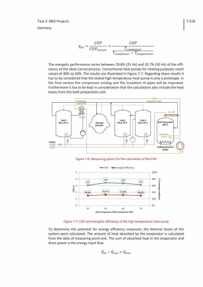
Task 3: R&D Projects
Germany
7-318
The exergetic performance varies between 29.8% (25 Hz) and 32.7% (50 Hz) of the effi-ciency of the ideal Carnot process. Conventional heat pumps for heating purposes reach values of 40% to 50%. The results are illustrated in Figure 7-7. Regarding these results it has to be considered that the tested high temperature heat pump is only a prototype. In the final version the compressor cooling and the insulation of pipes will be improved. Furthermore it has to be kept in consideration that the calculations also include the heat losses from the bath preparation unit.
Figure 7-6: Measuring points for the calculation of the COP
Figure 7-7: COP and exergetic efficiency of the high temperature heat pump
To determine the potential for energy efficiency measures, the thermal losses of the system were calculated. The amount of heat absorbed by the evaporator is calculated from the data of measuring point one. The sum of absorbed heat in the evaporator and drive power is the energy input flow.
3,13,4 3,3
3,1
29,8% 32,7% 31,8% 30,0%
0%
20%
40%
60%
80%
100%
0
1
2
3
4
5
25 50 60 70
exer
getic
eff
icie
ncy
[-]
COP
[-]
drive frequency of the compressor [Hz]
COP exergetic efficiency
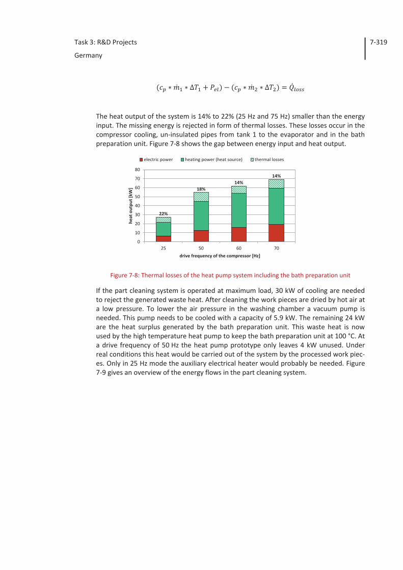
Task 3: R&D Projects
Germany
7-319
The heat output of the system is 14% to 22% (25 Hz and 75 Hz) smaller than the energy input. The missing energy is rejected in form of thermal losses. These losses occur in the compressor cooling, un-insulated pipes from tank 1 to the evaporator and in the bath preparation unit. Figure 7-8 shows the gap between energy input and heat output.
Figure 7-8: Thermal losses of the heat pump system including the bath preparation unit
If the part cleaning system is operated at maximum load, 30 kW of cooling are needed to reject the generated waste heat. After cleaning the work pieces are dried by hot air at a low pressure. To lower the air pressure in the washing chamber a vacuum pump is needed. This pump needs to be cooled with a capacity of 5.9 kW. The remaining 24 kW are the heat surplus generated by the bath preparation unit. This waste heat is now used by the high temperature heat pump to keep the bath preparation unit at 100 °C. At a drive frequency of 50 Hz the heat pump prototype only leaves 4 kW unused. Under real conditions this heat would be carried out of the system by the processed work piec-es. Only in 25 Hz mode the auxiliary electrical heater would probably be needed. Figure 7-9 gives an overview of the energy flows in the part cleaning system.
22%
18%14%
14%
0
10
20
30
40
50
60
70
80
25 50 60 70
heat
out
put [
kW]
drive frequency of the compressor [Hz]
electric power heating power (heat source) thermal losses
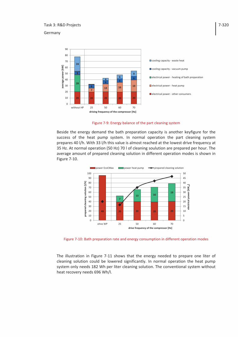
Task 3: R&D Projects
Germany
7-320
Figure 7-9: Energy balance of the part cleaning system
Beside the energy demand the bath preparation capacity is another keyfigure for the success of the heat pump system. In normal operation the part cleaning system prepares 40 l/h. With 33 l/h this value is almost reached at the lowest drive frequency at 35 Hz. At normal operation (50 Hz) 70 l of cleaning soulution are prepared per hour. The average amount of prepared cleaning solution in different operation modes is shown in Figure 7-10.
Figure 7-10: Bath preparation rate and energy consumption in different operation modes
The illustration in Figure 7-11 shows that the energy needed to prepare one liter of cleaning solution could be lowered significantly. In normal operation the heat pump system only needs 182 Wh per liter cleaning solution. The conventional system without heat recovery needs 696 Wh/l.
20 20 20 20 20
713 16 19
28
6
66 6
6
24
46
9
0
10
20
30
40
50
60
70
80
90
without HP 25 50 60 70
aver
age
pow
er [k
W]
driving frequency of the compressor [Hz]
cooling capacity - waste heat
cooling capacity - vacuum pump
electircal power - heating of bath preparation
electrical power - heat pump
electrical power - other consumers
48 20 20 20 20
713 16
19
0
5
10
15
20
25
30
35
40
45
50
0
10
20
30
40
50
60
70
80
90
100
ohne WP 25 50 60 70
elec
tric
al p
ower
[kW
el]
prep
ared
cle
anin
g so
lutio
n [l/
h]
drive frequency of the compressor [Hz]
power EcoCMax power heat pump prepared cleaning solution
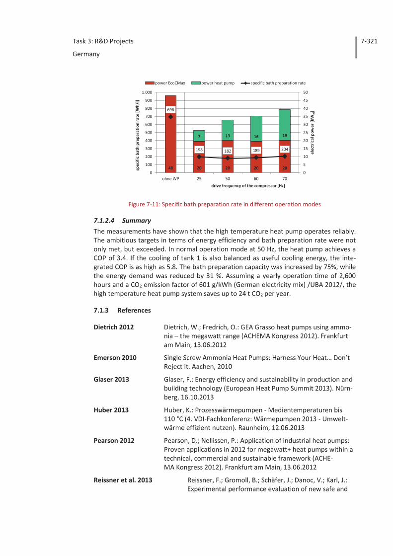
Task 3: R&D Projects
Germany
7-321
Figure 7-11: Specific bath preparation rate in different operation modes
7.1.2.4 Summary The measurements have shown that the high temperature heat pump operates reliably. The ambitious targets in terms of energy efficiency and bath preparation rate were not only met, but exceeded. In normal operation mode at 50 Hz, the heat pump achieves a COP of 3.4. If the cooling of tank 1 is also balanced as useful cooling energy, the inte-grated COP is as high as 5.8. The bath preparation capacity was increased by 75%, while the energy demand was reduced by 31 %. Assuming a yearly operation time of 2,600 hours and a CO2 emission factor of 601 g/kWh (German electricity mix) /UBA 2012/, the high temperature heat pump system saves up to 24 t CO2 per year.
7.1.3 References
Dietrich 2012 Dietrich, W.; Fredrich, O.: GEA Grasso heat pumps using ammo-nia – the megawatt range (ACHEMA Kongress 2012). Frankfurt am Main, 13.06.2012
Emerson 2010 Single Screw Ammonia Heat Pumps: Harness Your Heat… Don’t Reject It. Aachen, 2010
Glaser 2013 Glaser, F.: Energy efficiency and sustainability in production and building technology (European Heat Pump Summit 2013). Nürn-berg, 16.10.2013
Huber 2013 Huber, K.: Prozesswärmepumpen - Medientemperaturen bis 110 °C (4. VDI-Fachkonferenz: Wärmepumpen 2013 - Umwelt-wärme effizient nutzen). Raunheim, 12.06.2013
Pearson 2012 Pearson, D.; Nellissen, P.: Application of industrial heat pumps: Proven applications in 2012 for megawatt+ heat pumps within a technical, commercial and sustainable framework (ACHE-MA Kongress 2012). Frankfurt am Main, 13.06.2012
Reissner et al. 2013 Reissner, F.; Gromoll, B.; Schäfer, J.; Danoc, V.; Karl, J.: Experimental performance evaluation of new safe and
48 20 20 20 20
7 13 16 19
198 182 189 204
696
0
5
10
15
20
25
30
35
40
45
50
0
100
200
300
400
500
600
700
800
900
1.000
ohne WP 25 50 60 70
elec
tric
al p
ower
[kW
el]
spec
ific
bath
pre
para
tion
rate
[Wh/
l]
drive frequency of the compressor [Hz]
power EcoCMax power heat pump specific bath preparation rate
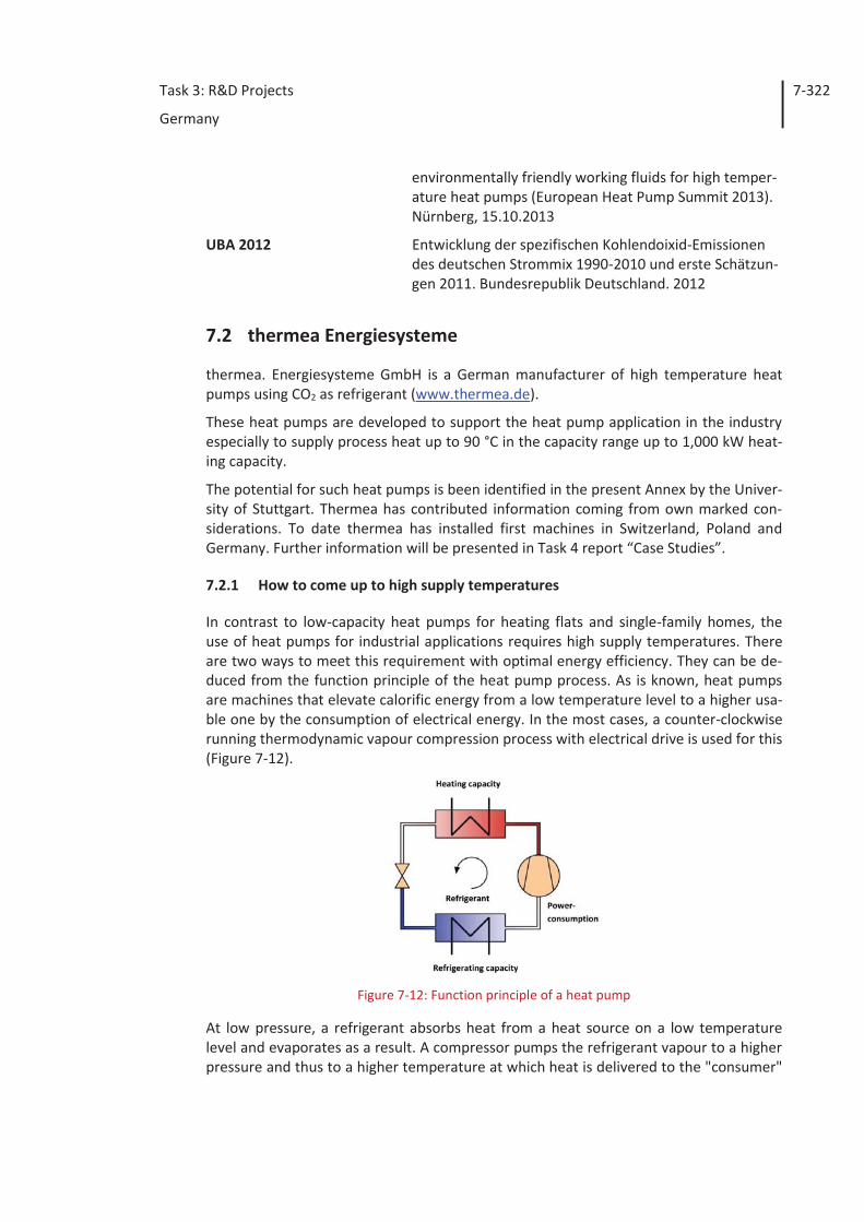
Task 3: R&D Projects
Germany
7-322
environmentally friendly working fluids for high temper-ature heat pumps (European Heat Pump Summit 2013). Nürnberg, 15.10.2013
UBA 2012 Entwicklung der spezifischen Kohlendoixid-Emissionen des deutschen Strommix 1990-2010 und erste Schätzun-gen 2011. Bundesrepublik Deutschland. 2012
7.2 thermea Energiesysteme
thermea. Energiesysteme GmbH is a German manufacturer of high temperature heat pumps using CO2 as refrigerant (www.thermea.de).
These heat pumps are developed to support the heat pump application in the industry especially to supply process heat up to 90 °C in the capacity range up to 1,000 kW heat-ing capacity.
The potential for such heat pumps is been identified in the present Annex by the Univer-sity of Stuttgart. Thermea has contributed information coming from own marked con-siderations. To date thermea has installed first machines in Switzerland, Poland and Germany. Further information will be presented in Task 4 report “Case Studies”.
7.2.1 How to come up to high supply temperatures
In contrast to low-capacity heat pumps for heating flats and single-family homes, the use of heat pumps for industrial applications requires high supply temperatures. There are two ways to meet this requirement with optimal energy efficiency. They can be de-duced from the function principle of the heat pump process. As is known, heat pumps are machines that elevate calorific energy from a low temperature level to a higher usa-ble one by the consumption of electrical energy. In the most cases, a counter-clockwise running thermodynamic vapour compression process with electrical drive is used for this (Figure 7-12).
Figure 7-12: Function principle of a heat pump
At low pressure, a refrigerant absorbs heat from a heat source on a low temperature level and evaporates as a result. A compressor pumps the refrigerant vapour to a higher pressure and thus to a higher temperature at which heat is delivered to the "consumer"
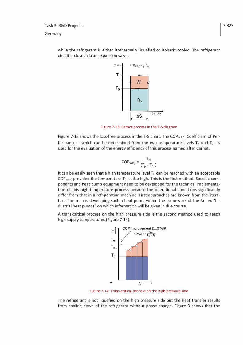
Task 3: R&D Projects
Germany
7-323
while the refrigerant is either isothermally liquefied or isobaric cooled. The refrigerant circuit is closed via an expansion valve.
Figure 7-13: Carnot process in the T-S diagram
Figure 7-13 shows the loss-free process in the T-S chart. The COPWP,C (Coefficient of Per-formance) - which can be determined from the two temperature levels TH und T0 - is used for the evaluation of the energy efficiency of this process named after Carnot.
COPWP,C= TH
(TH - T0 )
It can be easily seen that a high temperature level TH can be reached with an acceptable COPWP,C provided the temperature T0 is also high. This is the first method. Specific com-ponents and heat pump equipment need to be developed for the technical implementa-tion of this high-temperature process because the operational conditions significantly differ from that in a refrigeration machine. First approaches are known from the litera-ture. thermea is developing such a heat pump within the framework of the Annex "In-dustrial heat pumps" on which information will be given in due course.
A trans-critical process on the high pressure side is the second method used to reach high supply temperatures (Figure 7-14).
Figure 7-14: Trans-critical process on the high pressure side
The refrigerant is not liquefied on the high pressure side but the heat transfer results from cooling down of the refrigerant without phase change. Figure 3 shows that the
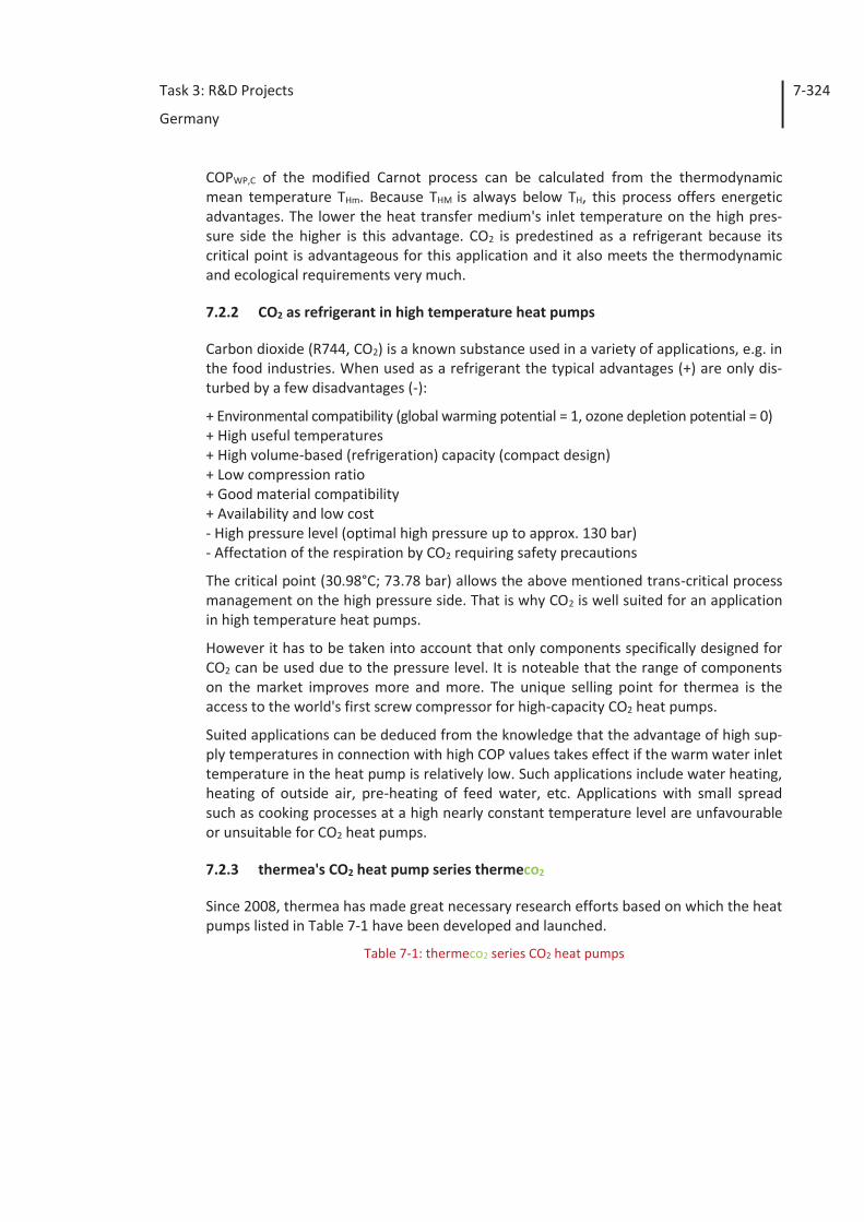
Task 3: R&D Projects
Germany
7-324
COPWP,C of the modified Carnot process can be calculated from the thermodynamic mean temperature THm. Because THM is always below TH, this process offers energetic advantages. The lower the heat transfer medium's inlet temperature on the high pres-sure side the higher is this advantage. CO2 is predestined as a refrigerant because its critical point is advantageous for this application and it also meets the thermodynamic and ecological requirements very much.
7.2.2 CO2 as refrigerant in high temperature heat pumps
Carbon dioxide (R744, CO2) is a known substance used in a variety of applications, e.g. in the food industries. When used as a refrigerant the typical advantages (+) are only dis-turbed by a few disadvantages (-):
+ Environmental compatibility (global warming potential = 1, ozone depletion potential = 0) + High useful temperatures + High volume-based (refrigeration) capacity (compact design) + Low compression ratio + Good material compatibility + Availability and low cost - High pressure level (optimal high pressure up to approx. 130 bar) - Affectation of the respiration by CO2 requiring safety precautions
The critical point (30.98°C; 73.78 bar) allows the above mentioned trans-critical process management on the high pressure side. That is why CO2 is well suited for an application in high temperature heat pumps.
However it has to be taken into account that only components specifically designed for CO2 can be used due to the pressure level. It is noteable that the range of components on the market improves more and more. The unique selling point for thermea is the access to the world's first screw compressor for high-capacity CO2 heat pumps.
Suited applications can be deduced from the knowledge that the advantage of high sup-ply temperatures in connection with high COP values takes effect if the warm water inlet temperature in the heat pump is relatively low. Such applications include water heating, heating of outside air, pre-heating of feed water, etc. Applications with small spread such as cooking processes at a high nearly constant temperature level are unfavourable or unsuitable for CO2 heat pumps.
7.2.3 thermea's CO2 heat pump series thermeco2
Since 2008, thermea has made great necessary research efforts based on which the heat pumps listed in Table 7-1 have been developed and launched.
Table 7-1: thermeco2 series CO2 heat pumps
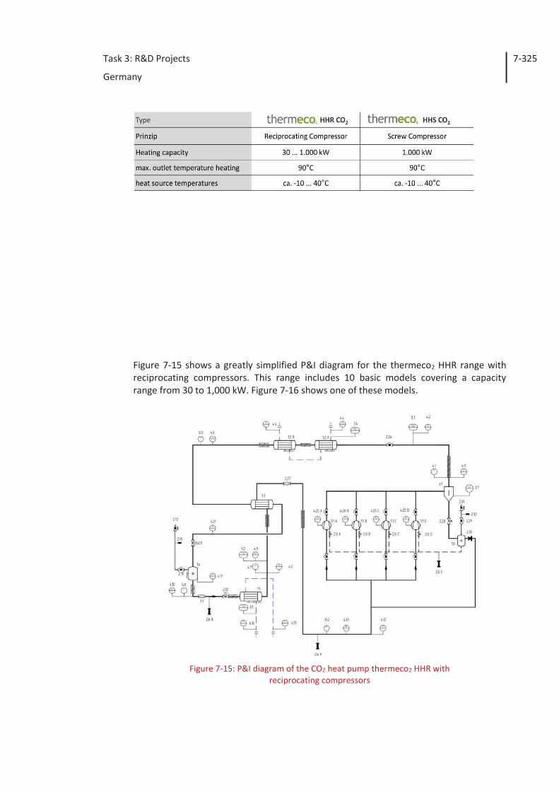
Task 3: R&D Projects
Germany
7-325
Figure 7-15 shows a greatly simplified P&I diagram for the thermeco2 HHR range with reciprocating compressors. This range includes 10 basic models covering a capacity range from 30 to 1,000 kW. Figure 7-16 shows one of these models.
Figure 7-15: P&I diagram of the CO2 heat pump thermeco2 HHR with reciprocating compressors
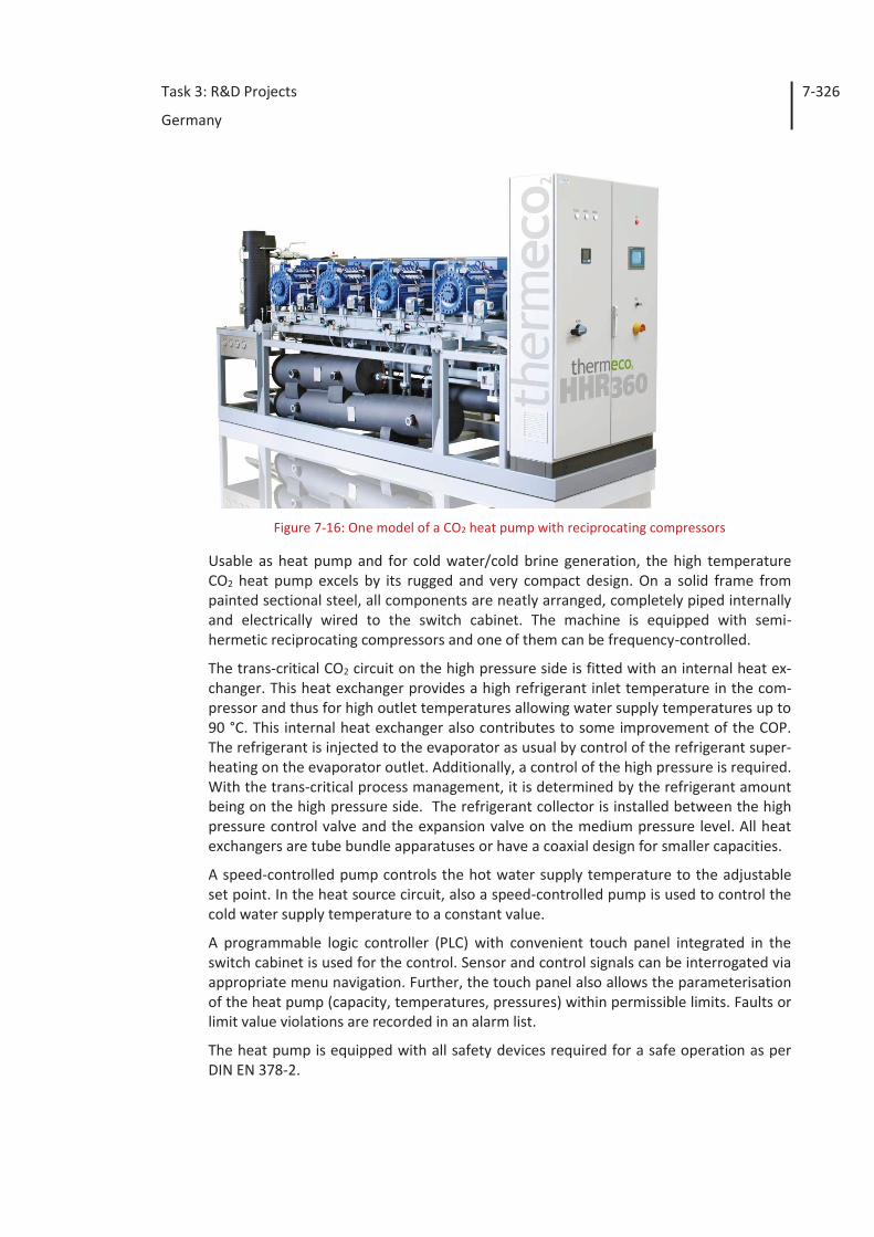
Task 3: R&D Projects
Germany
7-326
Figure 7-16: One model of a CO2 heat pump with reciprocating compressors
Usable as heat pump and for cold water/cold brine generation, the high temperature CO2 heat pump excels by its rugged and very compact design. On a solid frame from painted sectional steel, all components are neatly arranged, completely piped internally and electrically wired to the switch cabinet. The machine is equipped with semi-hermetic reciprocating compressors and one of them can be frequency-controlled.
The trans-critical CO2 circuit on the high pressure side is fitted with an internal heat ex-changer. This heat exchanger provides a high refrigerant inlet temperature in the com-pressor and thus for high outlet temperatures allowing water supply temperatures up to 90 °C. This internal heat exchanger also contributes to some improvement of the COP. The refrigerant is injected to the evaporator as usual by control of the refrigerant super-heating on the evaporator outlet. Additionally, a control of the high pressure is required. With the trans-critical process management, it is determined by the refrigerant amount being on the high pressure side. The refrigerant collector is installed between the high pressure control valve and the expansion valve on the medium pressure level. All heat exchangers are tube bundle apparatuses or have a coaxial design for smaller capacities.
A speed-controlled pump controls the hot water supply temperature to the adjustable set point. In the heat source circuit, also a speed-controlled pump is used to control the cold water supply temperature to a constant value.
A programmable logic controller (PLC) with convenient touch panel integrated in the switch cabinet is used for the control. Sensor and control signals can be interrogated via appropriate menu navigation. Further, the touch panel also allows the parameterisation of the heat pump (capacity, temperatures, pressures) within permissible limits. Faults or limit value violations are recorded in an alarm list.
The heat pump is equipped with all safety devices required for a safe operation as per DIN EN 378-2.
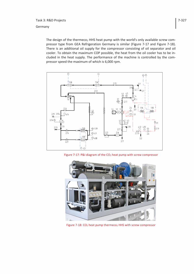
Task 3: R&D Projects
Germany
7-327
The design of the thermeco2 HHS heat pump with the world's only available screw com-pressor type from GEA Refrigeration Germany is similar (Figure 7-17 and Figure 7-18). There is an additional oil supply for the compressor consisting of oil separator and oil cooler. To obtain the maximum COP possible, the heat from the oil cooler has to be in-cluded in the heat supply. The performance of the machine is controlled by the com-pressor speed the maximum of which is 6,000 rpm.
Figure 7-17: P&I diagram of the CO2 heat pump with screw compressor
Figure 7-18: CO2 heat pump thermeco2 HHS with screw compressor
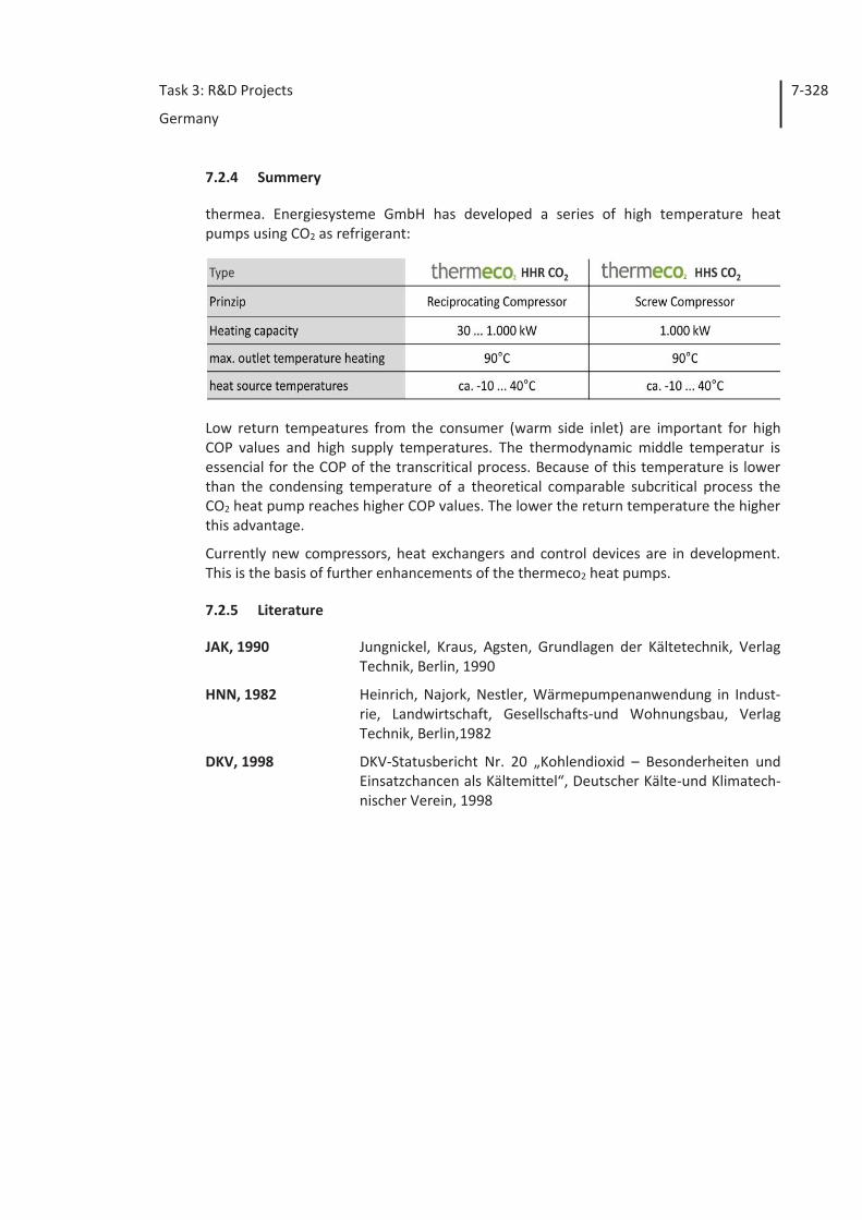
Task 3: R&D Projects
Germany
7-328
7.2.4 Summery
thermea. Energiesysteme GmbH has developed a series of high temperature heat pumps using CO2 as refrigerant:
Low return tempeatures from the consumer (warm side inlet) are important for high COP values and high supply temperatures. The thermodynamic middle temperatur is essencial for the COP of the transcritical process. Because of this temperature is lower than the condensing temperature of a theoretical comparable subcritical process the CO2 heat pump reaches higher COP values. The lower the return temperature the higher this advantage.
Currently new compressors, heat exchangers and control devices are in development. This is the basis of further enhancements of the thermeco2 heat pumps.
7.2.5 Literature
JAK, 1990 Jungnickel, Kraus, Agsten, Grundlagen der Kältetechnik, Verlag Technik, Berlin, 1990
HNN, 1982 Heinrich, Najork, Nestler, Wärmepumpenanwendung in Indust-rie, Landwirtschaft, Gesellschafts-und Wohnungsbau, Verlag Technik, Berlin,1982
DKV, 1998 DKV-Statusbericht Nr. 20 „Kohlendioxid – Besonderheiten und Einsatzchancen als Kältemittel“, Deutscher Kälte-und Klimatech-nischer Verein, 1998
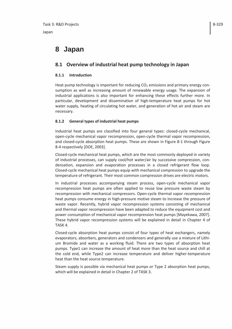
Task 3: R&D Projects
Japan
8-329
8 Japan
8.1 Overview of industrial heat pump technology in Japan
8.1.1 Introduction
Heat pump technology is important for reducing CO2 emissions and primary energy con-sumption as well as increasing amount of renewable energy usage. The expansion of industrial applications is also important for enhancing these effects further more. In particular, development and dissemination of high-temperature heat pumps for hot water supply, heating of circulating hot water, and generation of hot air and steam are necessary.
8.1.2 General types of industrial heat pumps
Industrial heat pumps are classified into four general types: closed-cycle mechanical, open-cycle mechanical vapor recompression, open-cycle thermal vapor recompression, and closed-cycle absorption heat pumps. These are shown in Figure 8-1 through Figure 8-4 respectively [DOE, 2003].
Closed-cycle mechanical heat pumps, which are the most commonly deployed in variety of industrial processes, can supply cool/hot water/air by successive compression, con-densation, expansion and evaporation processes in a closed refrigerant flow loop. Closed-cycle mechanical heat pumps equip with mechanical compression to upgrade the temperature of refrigerant. Their most common compression drives are electric motors.
In industrial processes accompanying steam process, open-cycle mechanical vapor recompression heat pumps are often applied to reuse low pressure waste steam by recompression with mechanical compressors. Open-cycle thermal vapor recompression heat pumps consume energy in high-pressure motive steam to increase the pressure of waste vapor. Recently, hybrid vapor recompression systems consisting of mechanical and thermal vapor recompression have been adapted to reduce the equipment cost and power consumption of mechanical vapor recompression heat pumps [Mayekawa, 2007]. These hybrid vapor recompression systems will be explained in detail in Chapter 4 of TASK 4.
Closed-cycle absorption heat pumps consist of four types of heat exchangers, namely evaporators, absorbers, generators and condensers and generally use a mixture of Lithi-um Bromide and water as a working fluid. There are two types of absorption heat pumps. Type1 can increase the amount of heat more than the heat source and chill at the cold end, while Type2 can increase temperature and deliver higher-temperature heat than the heat source temperature.
Steam supply is possible via mechanical heat pumps or Type 2 absorption heat pumps, which will be explained in detail in Chapter 2 of TASK 3.
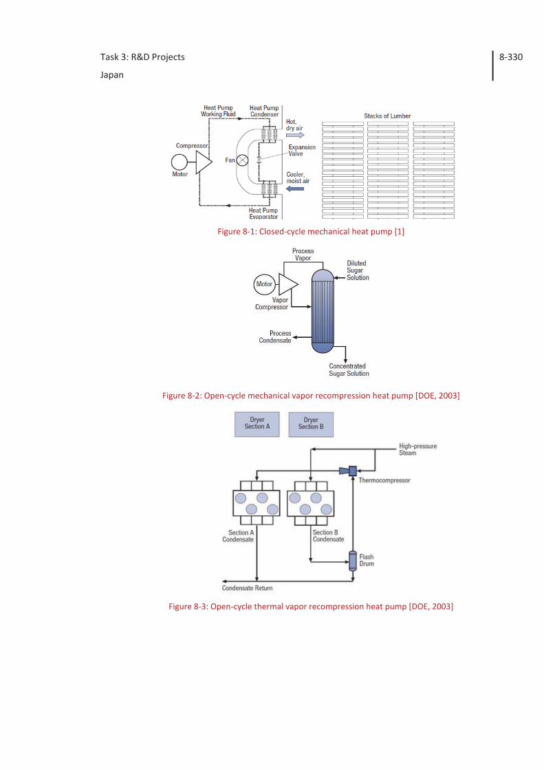
Task 3: R&D Projects
Japan
8-330
Figure 8-1: Closed-cycle mechanical heat pump [1]
Figure 8-2: Open-cycle mechanical vapor recompression heat pump [DOE, 2003]
Figure 8-3: Open-cycle thermal vapor recompression heat pump [DOE, 2003]
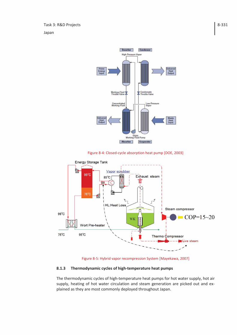
Task 3: R&D Projects
Japan
8-331
Figure 8-4: Closed-cycle absorption heat pump [DOE, 2003]
Figure 8-5: Hybrid vapor recompression System [Mayekawa, 2007]
8.1.3 Thermodynamic cycles of high-temperature heat pumps
The thermodynamic cycles of high-temperature heat pumps for hot water supply, hot air supply, heating of hot water circulation and steam generation are picked out and ex-plained as they are most commonly deployed throughout Japan.
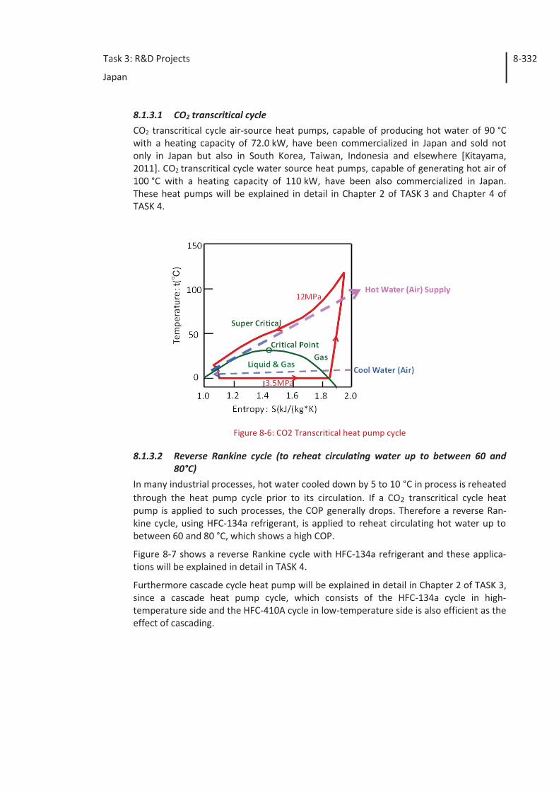
Task 3: R&D Projects
Japan
8-332
8.1.3.1 CO2 transcritical cycle CO2 transcritical cycle air-source heat pumps, capable of producing hot water of 90 °C with a heating capacity of 72.0 kW, have been commercialized in Japan and sold not only in Japan but also in South Korea, Taiwan, Indonesia and elsewhere [Kitayama, 2011]. CO2 transcritical cycle water source heat pumps, capable of generating hot air of 100 °C with a heating capacity of 110 kW, have been also commercialized in Japan. These heat pumps will be explained in detail in Chapter 2 of TASK 3 and Chapter 4 of TASK 4.
Figure 8-6: CO2 Transcritical heat pump cycle
8.1.3.2 Reverse Rankine cycle (to reheat circulating water up to between 60 and 80°C)
In many industrial processes, hot water cooled down by 5 to 10 °C in process is reheated through the heat pump cycle prior to its circulation. If a CO2 transcritical cycle heat pump is applied to such processes, the COP generally drops. Therefore a reverse Ran-kine cycle, using HFC-134a refrigerant, is applied to reheat circulating hot water up to between 60 and 80 °C, which shows a high COP.
Figure 8-7 shows a reverse Rankine cycle with HFC-134a refrigerant and these applica-tions will be explained in detail in TASK 4.
Furthermore cascade cycle heat pump will be explained in detail in Chapter 2 of TASK 3, since a cascade heat pump cycle, which consists of the HFC-134a cycle in high-temperature side and the HFC-410A cycle in low-temperature side is also efficient as the effect of cascading.
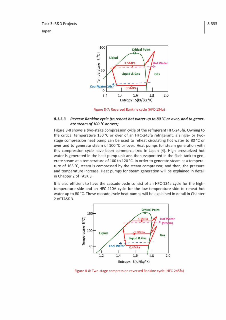
Task 3: R&D Projects
Japan
8-333
Figure 8-7: Reversed Rankine cycle (HFC-134a)
8.1.3.3 Reverse Rankine cycle (to reheat hot water up to 80 °C or over, and to gener-ate steam of 100 °C or over)
Figure 8-8 shows a two-stage compression cycle of the refrigerant HFC-245fa. Owning to the critical temperature 150 °C or over of an HFC-245fa refrigerant, a single- or two-stage compression heat pump can be used to reheat circulating hot water to 80 °C or over and to generate steam of 100 °C or over. Heat pumps for steam generation with this compression cycle have been commercialized in Japan [4]. High pressurized hot water is generated in the heat pump unit and then evaporated in the flash tank to gen-erate steam at a temperature of 100 to 120 °C. In order to generate steam at a tempera-ture of 165 °C, steam is compressed by the steam compressor, and then, the pressure and temperature increase. Heat pumps for steam generation will be explained in detail in Chapter 2 of TASK 3.
It is also efficient to have the cascade cycle consist of an HFC-134a cycle for the high-temperature side and an HFC-410A cycle for the low-temperature side to reheat hot water up to 80 °C. These cascade cycle heat pumps will be explained in detail in Chapter 2 of TASK 3.
Figure 8-8: Two-stage compression reversed Rankine cycle (HFC-245fa)
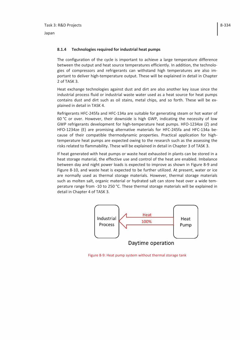
Task 3: R&D Projects
Japan
8-334
8.1.4 Technologies required for industrial heat pumps
The configuration of the cycle is important to achieve a large temperature difference between the output and heat source temperatures efficiently. In addition, the technolo-gies of compressors and refrigerants can withstand high temperatures are also im-portant to deliver high-temperature output. These will be explained in detail in Chapter 2 of TASK 3.
Heat exchange technologies against dust and dirt are also another key issue since the industrial process fluid or industrial waste water used as a heat source for heat pumps contains dust and dirt such as oil stains, metal chips, and so forth. These will be ex-plained in detail in TASK 4.
Refrigerants HFC-245fa and HFC-134a are suitable for generating steam or hot water of 60 °C or over. However, their downside is high GWP, indicating the necessity of low GWP refrigerants development for high-temperature heat pumps. HFO-1234ze (Z) and HFO-1234ze (E) are promising alternative materials for HFC-245fa and HFC-134a be-cause of their compatible thermodynamic properties. Practical application for high-temperature heat pumps are expected owing to the research such as the assessing the risks related to flammability. These will be explained in detail in Chapter 3 of TASK 3.
If heat generated with heat pumps or waste heat exhausted in plants can be stored in a heat storage material, the effective use and control of the heat are enabled. Imbalance between day and night power loads is expected to improve as shown in Figure 8-9 and Figure 8-10, and waste heat is expected to be further utilized. At present, water or ice are normally used as thermal storage materials. However, thermal storage materials such as molten salt, organic material or hydrated salt can store heat over a wide tem-perature range from -10 to 250 °C. These thermal storage materials will be explained in detail in Chapter 4 of TASK 3.
Figure 8-9: Heat pump system without thermal storage tank
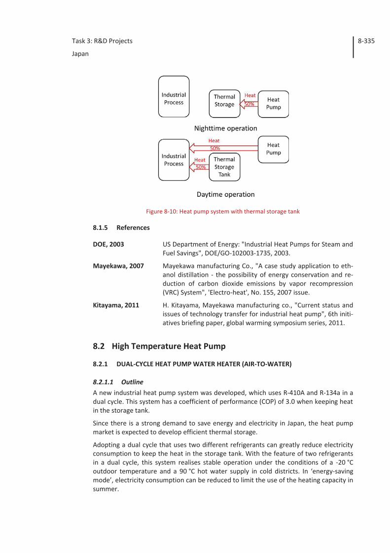
Task 3: R&D Projects
Japan
8-335
Figure 8-10: Heat pump system with thermal storage tank
8.1.5 References
DOE, 2003 US Department of Energy: "Industrial Heat Pumps for Steam and Fuel Savings", DOE/GO-102003-1735, 2003.
Mayekawa, 2007 Mayekawa manufacturing Co., "A case study application to eth-anol distillation - the possibility of energy conservation and re-duction of carbon dioxide emissions by vapor recompression (VRC) System", 'Electro-heat', No. 155, 2007 issue.
Kitayama, 2011 H. Kitayama, Mayekawa manufacturing co., "Current status and issues of technology transfer for industrial heat pump", 6th initi-atives briefing paper, global warming symposium series, 2011.
8.2 High Temperature Heat Pump
8.2.1 DUAL-CYCLE HEAT PUMP WATER HEATER (AIR-TO-WATER)
8.2.1.1 Outline A new industrial heat pump system was developed, which uses R-410A and R-134a in a dual cycle. This system has a coefficient of performance (COP) of 3.0 when keeping heat in the storage tank.
Since there is a strong demand to save energy and electricity in Japan, the heat pump market is expected to develop efficient thermal storage.
Adopting a dual cycle that uses two different refrigerants can greatly reduce electricity consumption to keep the heat in the storage tank. With the feature of two refrigerants in a dual cycle, this system realises stable operation under the conditions of a -20 °C outdoor temperature and a 90 °C hot water supply in cold districts. In ‘energy-saving mode’, electricity consumption can be reduced to limit the use of the heating capacity in summer.
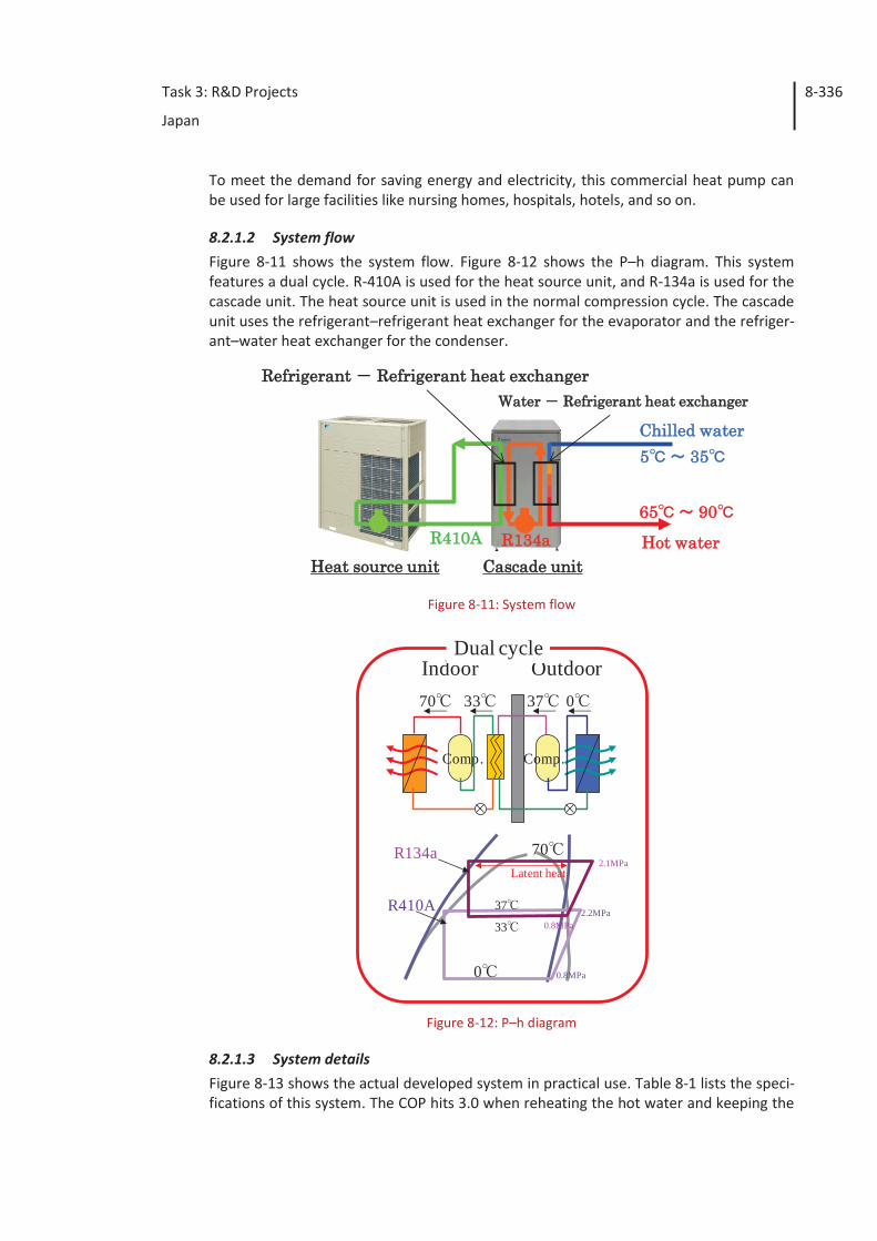
Task 3: R&D Projects
Japan
8-336
To meet the demand for saving energy and electricity, this commercial heat pump can be used for large facilities like nursing homes, hospitals, hotels, and so on.
8.2.1.2 System flow Figure 8-11 shows the system flow. Figure 8-12 shows the P–h diagram. This system features a dual cycle. R-410A is used for the heat source unit, and R-134a is used for the cascade unit. The heat source unit is used in the normal compression cycle. The cascade unit uses the refrigerant–refrigerant heat exchanger for the evaporator and the refriger-ant–water heat exchanger for the condenser.
Figure 8-11: System flow
Figure 8-12: P–h diagram
8.2.1.3 System details Figure 8-13 shows the actual developed system in practical use. Table 8-1 lists the speci-fications of this system. The COP hits 3.0 when reheating the hot water and keeping the
CCascade unitHeat source unit
Refrigerant Refrigerant heat exchanger
R134aR410A Hot water
Chilled water
65 90
5 35
Water Refrigerant heat exchanger
Indoor Outdoor
Comp.
070
Comp.
2.1MPa
0
Dual cycle
3733
37
70Latent heat
0.8MPa
2.2MPa0.8MPa
R134a
R410A33
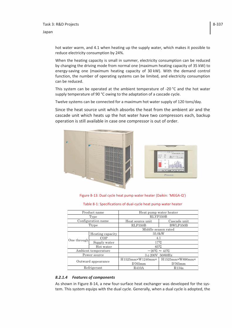
Task 3: R&D Projects
Japan
8-337
hot water warm, and 4.1 when heating up the supply water, which makes it possible to reduce electricity consumption by 24%.
When the heating capacity is small in summer, electricity consumption can be reduced by changing the driving mode from normal one (maximum heating capacity of 35 kW) to energy-saving one (maximum heating capacity of 30 kW). With the demand control function, the number of operating systems can be limited, and electricity consumption can be reduced.
This system can be operated at the ambient temperature of -20 °C and the hot water supply temperature of 90 °C owing to the adaptation of a cascade cycle.
Twelve systems can be connected for a maximum hot water supply of 120 tons/day.
Since the heat source unit which absorbs the heat from the ambient air and the cascade unit which heats up the hot water have two compressors each, backup operation is still available in case one compressor is out of order.
Figure 8-13: Dual cycle heat pump water heater (Daikin: ‘MEGA-Q’)
Table 8-1: Specifications of dual-cycle heat pump water heater
8.2.1.4 Features of components As shown in Figure 8-14, a new four-surface heat exchanger was developed for the sys-tem. This system equips with the dual cycle. Generally, when a dual cycle is adopted, the
Heat source unit Cascade unitRLP350B BWLP350B
Heating capacityCOP
Supply waterHot water
H1525mm×W1240mm×D765mm
H1525mm×W890mm×D765mm
R410A R134a
RLYP350BHeat pump water heater
Middle season rated35.0kW
17
Product nameType
Configuration nameTtype
Refrigerant
One through
Ambient temperature
4.1
Power source
Outward appearance
20 433 200V 50/60Hz
65
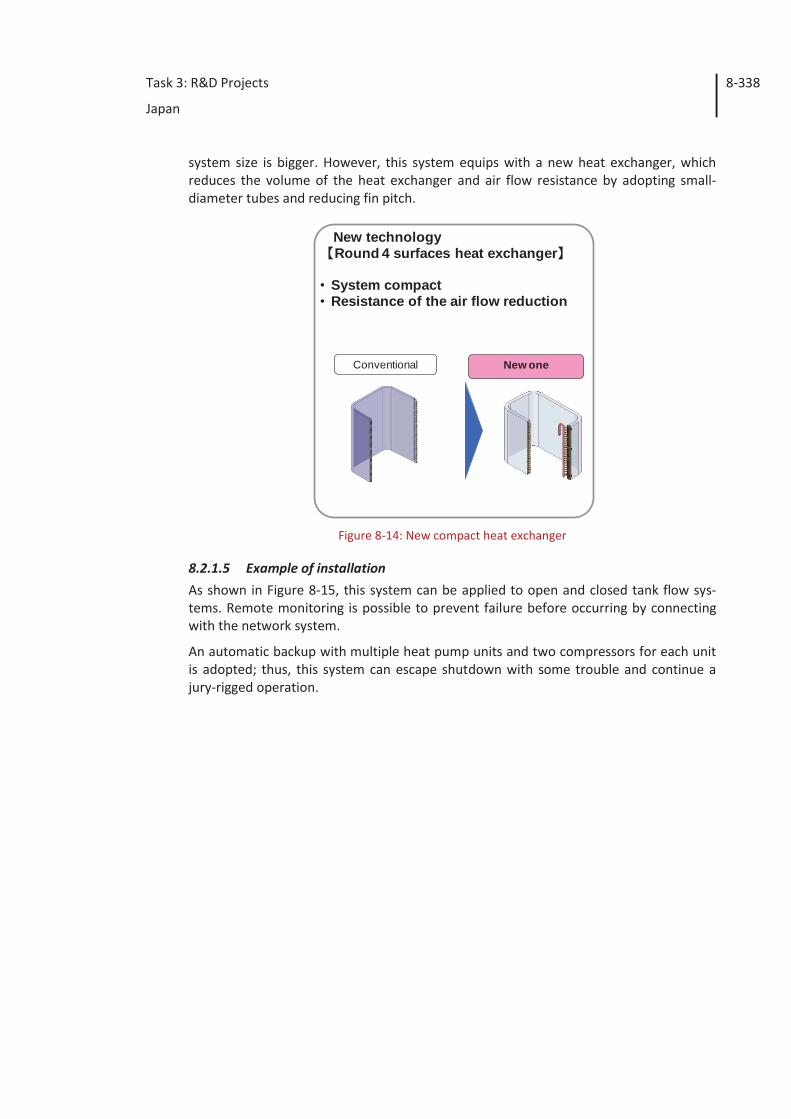
Task 3: R&D Projects
Japan
8-338
system size is bigger. However, this system equips with a new heat exchanger, which reduces the volume of the heat exchanger and air flow resistance by adopting small-diameter tubes and reducing fin pitch.
Figure 8-14: New compact heat exchanger
8.2.1.5 Example of installation As shown in Figure 8-15, this system can be applied to open and closed tank flow sys-tems. Remote monitoring is possible to prevent failure before occurring by connecting with the network system.
An automatic backup with multiple heat pump units and two compressors for each unit is adopted; thus, this system can escape shutdown with some trouble and continue a jury-rigged operation.
Conventional New one
New technologyRound 4 surfaces heat exchanger
• System compact• Resistance of the air flow reduction
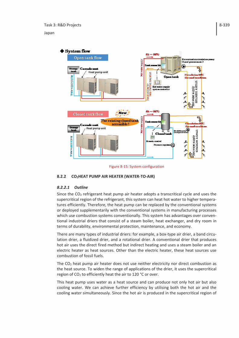
Task 3: R&D Projects
Japan
8-339
Figure 8-15: System configuration
8.2.2 CO2HEAT PUMP AIR HEATER (WATER-TO-AIR)
8.2.2.1 Outline Since the CO2 refrigerant heat pump air heater adopts a transcritical cycle and uses the supercritical region of the refrigerant, this system can heat hot water to higher tempera-tures efficiently. Therefore, the heat pump can be replaced by the conventional systems or deployed supplementarily with the conventional systems in manufacturing processes which use combustion systems conventionally. This system has advantages over conven-tional industrial driers that consist of a steam boiler, heat exchanger, and dry room in terms of durability, environmental protection, maintenance, and economy.
There are many types of industrial driers: for example, a box-type air drier, a band circu-lation drier, a fluidized drier, and a rotational drier. A conventional drier that produces hot air uses the direct fired method but indirect heating and uses a steam boiler and an electric heater as heat sources. Other than the electric heater, these heat sources use combustion of fossil fuels.
The CO2 heat pump air heater does not use neither electricity nor direct combustion as the heat source. To widen the range of applications of the drier, it uses the supercritical region of CO2 to efficiently heat the air to 120 °C or over.
This heat pump uses water as a heat source and can produce not only hot air but also cooling water. We can achieve further efficiency by utilising both the hot air and the cooling water simultaneously. Since the hot air is produced in the supercritical region of
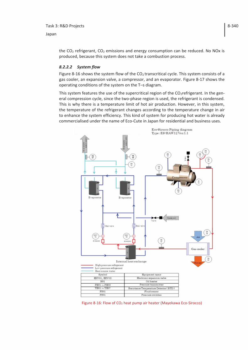
Task 3: R&D Projects
Japan
8-340
the CO2 refrigerant, CO2 emissions and energy consumption can be reduced. No NOx is produced, because this system does not take a combustion process.
8.2.2.2 System flow Figure 8-16 shows the system flow of the CO2 transcritical cycle. This system consists of a gas cooler, an expansion valve, a compressor, and an evaporator. Figure 8-17 shows the operating conditions of the system on the T–s diagram.
This system features the use of the supercritical region of the CO2refrigerant. In the gen-eral compression cycle, since the two-phase region is used, the refrigerant is condensed. This is why there is a temperature limit of hot air production. However, in this system, the temperature of the refrigerant changes according to the temperature change in air to enhance the system efficiency. This kind of system for producing hot water is already commercialised under the name of Eco-Cute in Japan for residential and business uses.
Figure 8-16: Flow of CO2 heat pump air heater (Mayekawa Eco-Sirocco)
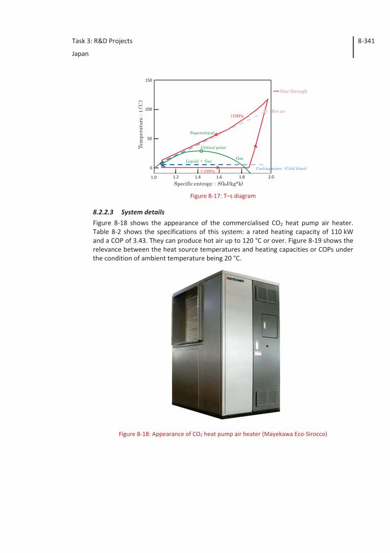
Task 3: R&D Projects
Japan
8-341
Figure 8-17: T–s diagram
8.2.2.3 System details Figure 8-18 shows the appearance of the commercialised CO2 heat pump air heater. Table 8-2 shows the specifications of this system: a rated heating capacity of 110 kW and a COP of 3.43. They can produce hot air up to 120 °C or over. Figure 8-19 shows the relevance between the heat source temperatures and heating capacities or COPs under the condition of ambient temperature being 20 °C.
Figure 8-18: Appearance of CO2 heat pump air heater (Mayekawa Eco-Sirocco)
Cooling water (Cold blast)0
50
100
150
Liquid Gas Gas
Supercritical
Critical pointTem
pera
ture
t()
Hot air
One through
12MPa
3.5MPa3.5MPa1.0 1.2 1.4 1.6 1.8 2.0
Specific entropy S(kJ/kg*k)
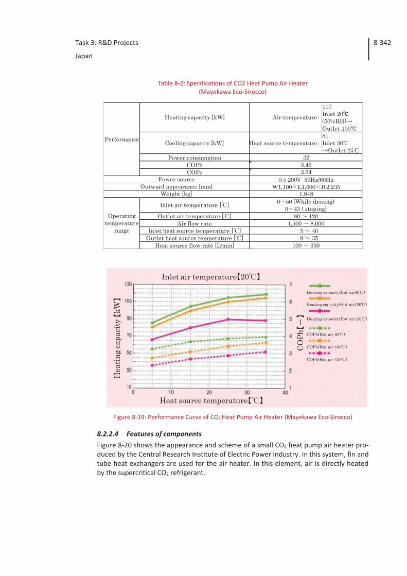
Task 3: R&D Projects
Japan
8-342
Table 8-2: Specifications of CO2 Heat Pump Air Heater (Mayekawa Eco-Sirocco)
Figure 8-19: Performance Curve of CO2 Heat Pump Air Heater (Mayekawa Eco-Sirocco)
8.2.2.4 Features of components Figure 8-20 shows the appearance and scheme of a small CO2 heat pump air heater pro-duced by the Central Research Institute of Electric Power Industry. In this system, fin and tube heat exchangers are used for the air heater. In this element, air is directly heated by the supercritical CO2 refrigerant.
Heating capacity [kW] Air temperature
110Inlet 20(50%RH)Outlet 100
Cooling capacity [kW] Heat source temperature81Inlet 30
Outlet 25Power consumption
COPhCOPc
Inlet air temperature [ ]
Outlet air temperature [ ]Air flow rate
Inlet heat source temperature [ ]Outlet heat source temperature [ ]
Heat source flow rate [L/min]
Operatingtemperature
range
0 50 (While driving)0 43 ( stoping)
80 1201,500 8,000
5 409 35
100 330
Weight [kg]
3 200V 50Hz/60HzW1,100 L1,600 H2,235
1,948
Performance
323.432.54
Power sourceOutward appearance [mm]
COPh
Heat source temperature
Inlet air temperature 20
Hea
ting
capa
city
kW
Heating capacity(Hot air80 )
Heating capacity(Hot air100 )
Heating capacity(Hot air120 )
COPh(Hot air 80 )
COPh(Hot air 100 )
COPh(Hot air 120 )
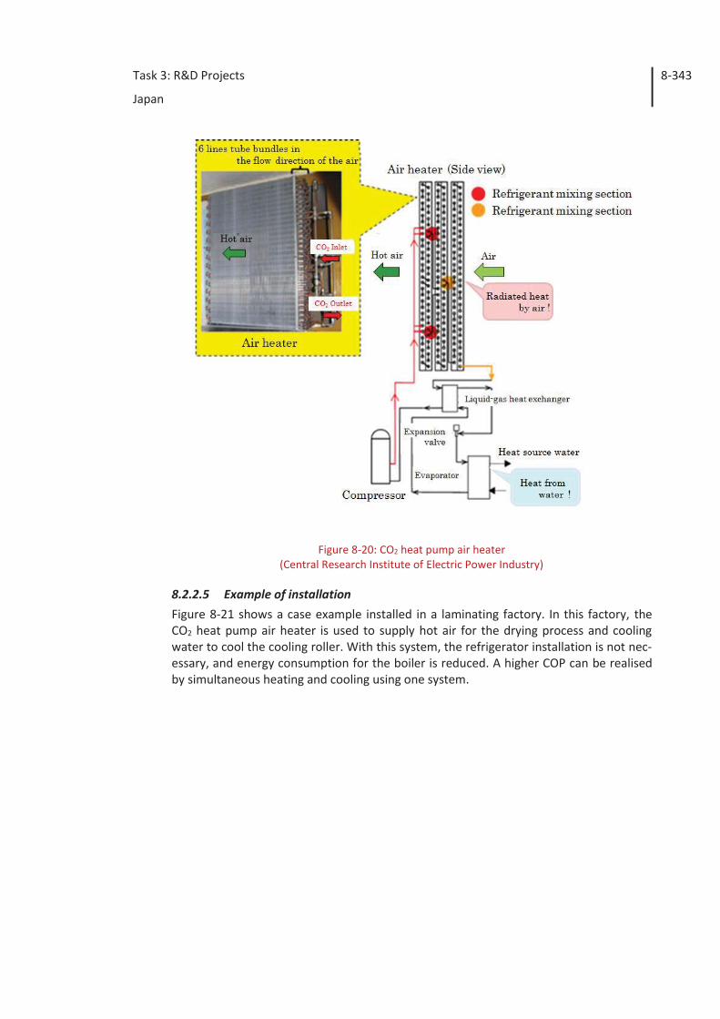
Task 3: R&D Projects
Japan
8-343
Figure 8-20: CO2 heat pump air heater
(Central Research Institute of Electric Power Industry)
8.2.2.5 Example of installation Figure 8-21 shows a case example installed in a laminating factory. In this factory, the CO2 heat pump air heater is used to supply hot air for the drying process and cooling water to cool the cooling roller. With this system, the refrigerator installation is not nec-essary, and energy consumption for the boiler is reduced. A higher COP can be realised by simultaneous heating and cooling using one system.
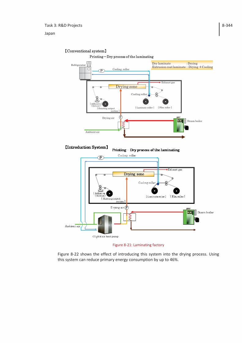
Task 3: R&D Projects
Japan
8-344
Figure 8-21: Laminating factory
Figure 8-22 shows the effect of introducing this system into the drying process. Using this system can reduce primary energy consumption by up to 46%.
PPrinting Dry process of the laminating Conventional system
Cooling roller
[ Hoisting output section ]
[ Adhesive ]( Solvent )
Cooling roller
[ Laminate roller ] [ Film roller ]
Drying zone
Refrigerator
Steam boiler
Ambient air
Drying air
Exhaust gas
Dry laminate DryingExtrusion coat laminate Drying Cooling
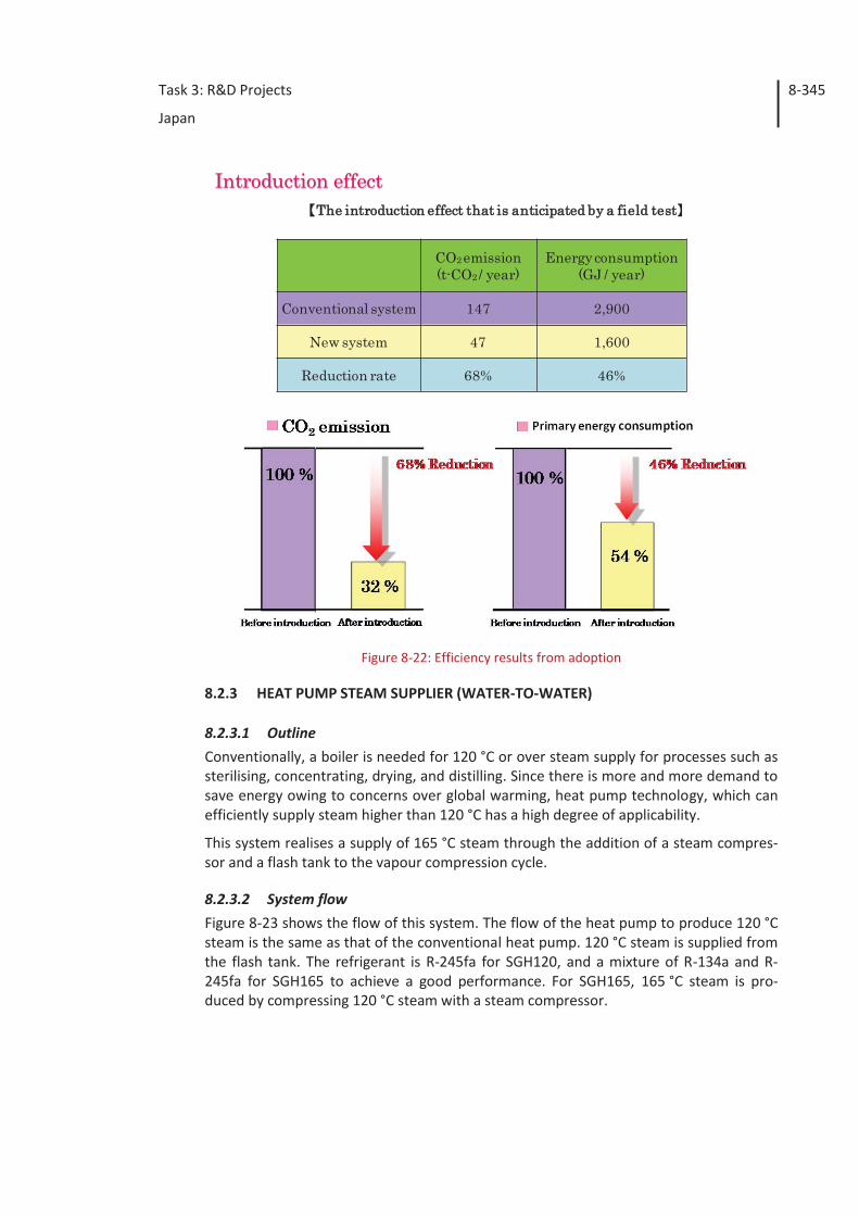
Task 3: R&D Projects
Japan
8-345
Figure 8-22: Efficiency results from adoption
8.2.3 HEAT PUMP STEAM SUPPLIER (WATER-TO-WATER)
8.2.3.1 Outline Conventionally, a boiler is needed for 120 °C or over steam supply for processes such as sterilising, concentrating, drying, and distilling. Since there is more and more demand to save energy owing to concerns over global warming, heat pump technology, which can efficiently supply steam higher than 120 °C has a high degree of applicability.
This system realises a supply of 165 °C steam through the addition of a steam compres-sor and a flash tank to the vapour compression cycle.
8.2.3.2 System flow Figure 8-23 shows the flow of this system. The flow of the heat pump to produce 120 °C steam is the same as that of the conventional heat pump. 120 °C steam is supplied from the flash tank. The refrigerant is R-245fa for SGH120, and a mixture of R-134a and R-245fa for SGH165 to achieve a good performance. For SGH165, 165 °C steam is pro-duced by compressing 120 °C steam with a steam compressor.
The introduction effect that is anticipated by a field test
CO2 emission(t-CO2 / year)
Energy consumption(GJ / year)
Conventional system 147 2,900
New system 47 1,600
Reduction rate 68% 46%
Introduction effect
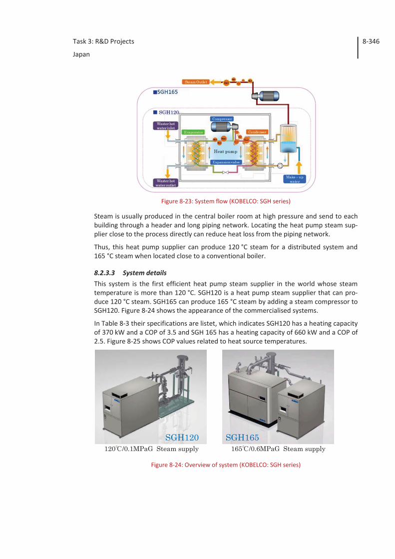
Task 3: R&D Projects
Japan
8-346
Figure 8-23: System flow (KOBELCO: SGH series)
Steam is usually produced in the central boiler room at high pressure and send to each building through a header and long piping network. Locating the heat pump steam sup-plier close to the process directly can reduce heat loss from the piping network.
Thus, this heat pump supplier can produce 120 °C steam for a distributed system and 165 °C steam when located close to a conventional boiler.
8.2.3.3 System details This system is the first efficient heat pump steam supplier in the world whose steam temperature is more than 120 °C. SGH120 is a heat pump steam supplier that can pro-duce 120 °C steam. SGH165 can produce 165 °C steam by adding a steam compressor to SGH120. Figure 8-24 shows the appearance of the commercialised systems.
In Table 8-3 their specifications are listet, which indicates SGH120 has a heating capacity of 370 kW and a COP of 3.5 and SGH 165 has a heating capacity of 660 kW and a COP of 2.5. Figure 8-25 shows COP values related to heat source temperatures.
Figure 8-24: Overview of system (KOBELCO: SGH series)
SGH120120 /0.1MPaG Steam supply
SGH165165 /0.6MPaG Steam supply
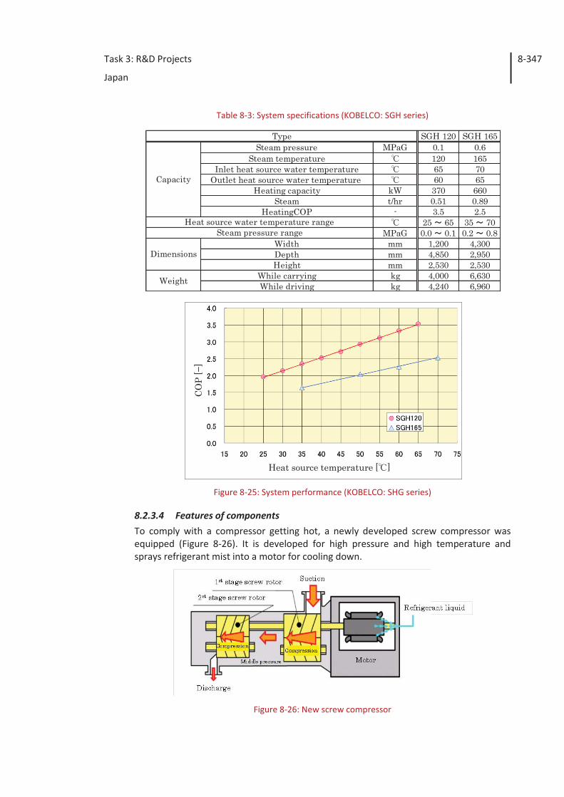
Task 3: R&D Projects
Japan
8-347
Table 8-3: System specifications (KOBELCO: SGH series)
Figure 8-25: System performance (KOBELCO: SHG series)
8.2.3.4 Features of components To comply with a compressor getting hot, a newly developed screw compressor was equipped (Figure 8-26). It is developed for high pressure and high temperature and sprays refrigerant mist into a motor for cooling down.
Figure 8-26: New screw compressor
SGH 120 SGH 165Steam pressure MPaG 0.1 0.6
Steam temperature 120 165Inlet heat source water temperature 65 70
Outlet heat source water temperature 60 65Heating capacity kW 370 660
Steam t/hr 0.51 0.89HeatingCOP - 3.5 2.5
25 65 35 70MPaG 0.0 0.1 0.2 0.8
Width mm 1,200 4,300Depth mm 4,850 2,950Height mm 2,530 2,530
While carrying kg 4,000 6,630While driving kg 4,240 6,960
Type
Capacity
Weight
Dimensions
Heat source water temperature rangeSteam pressure range
Heat source temperature [ ]
CO
P [−
]
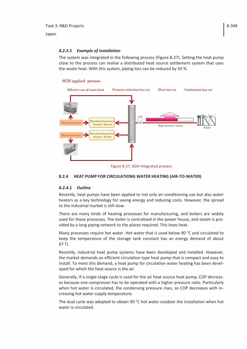
Task 3: R&D Projects
Japan
8-348
8.2.3.5 Example of installation The system was integrated in the following process (Figure 8-27). Setting the heat pump close to the process can realise a distributed heat source settlement system that uses the waste heat. With this system, piping loss can be reduced by 50 %.
Figure 8-27: SGH-integrated process
8.2.4 HEAT PUMP FOR CIRCULATIONG WATER HEATING (AIR-TO-WATER)
8.2.4.1 Outline Recently, heat pumps have been applied to not only air-conditioning use but also water heaters as a key technology for saving energy and reducing costs. However, the spread to the industrial market is still slow.
There are many kinds of heating processes for manufacturing, and boilers are widely used for these processes. The boiler is centralised in the power house, and steam is pro-vided by a long piping network to the places required. This loses heat.
Many processes require hot water. Hot water that is used below 90 °C and circulated to keep the temperature of the storage tank constant has an energy demand of about 67 TJ.
Recently, industrial heat pump systems have been developed and installed. However, the market demands an efficient circulation type heat pump that is compact and easy to install. To meet this demand, a heat pump for circulation water heating has been devel-oped for which the heat source is the air.
Generally, if a single-stage cycle is used for the air heat source heat pump, COP decreas-es because one compressor has to be operated with a higher pressure ratio. Particularly when hot water is circulated, the condensing pressure rises, so COP decreases with in-creasing hot water supply temperature.
The dual cycle was adopted to obtain 90 °C hot water outdoor the installation when hot water is circulated.
Med
ium
pre
ssur
e st
eam
hea
der
CSV
High pressure steamBoiler
Manufacturing processExample Reaction
Manufacturing processExample Sterilize
Waste hot water
Waste hot water
SGH applied process
Effective use of waste heat Pressure reduction loss cut Heat loss cut Combustion loss cut
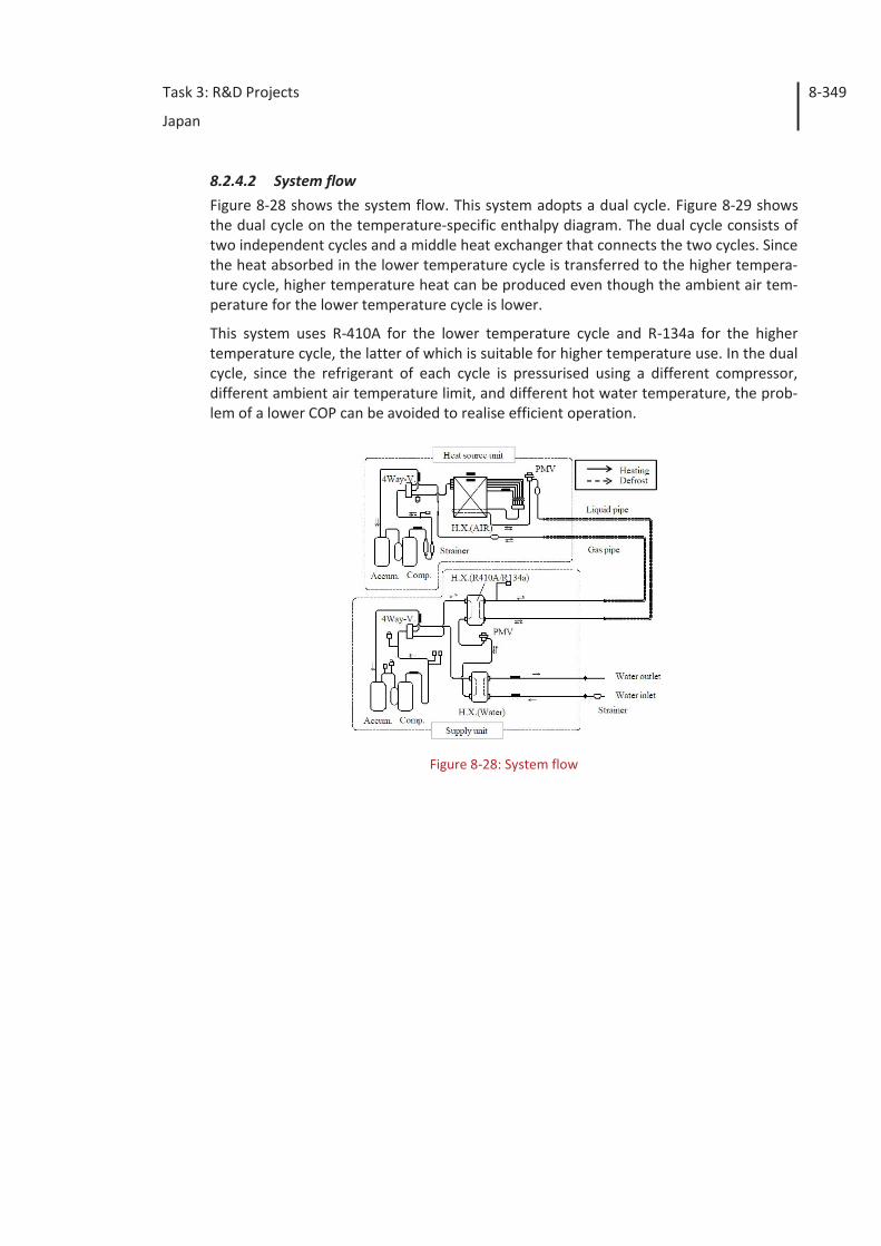
Task 3: R&D Projects
Japan
8-349
8.2.4.2 System flow Figure 8-28 shows the system flow. This system adopts a dual cycle. Figure 8-29 shows the dual cycle on the temperature-specific enthalpy diagram. The dual cycle consists of two independent cycles and a middle heat exchanger that connects the two cycles. Since the heat absorbed in the lower temperature cycle is transferred to the higher tempera-ture cycle, higher temperature heat can be produced even though the ambient air tem-perature for the lower temperature cycle is lower.
This system uses R-410A for the lower temperature cycle and R-134a for the higher temperature cycle, the latter of which is suitable for higher temperature use. In the dual cycle, since the refrigerant of each cycle is pressurised using a different compressor, different ambient air temperature limit, and different hot water temperature, the prob-lem of a lower COP can be avoided to realise efficient operation.
Figure 8-28: System flow
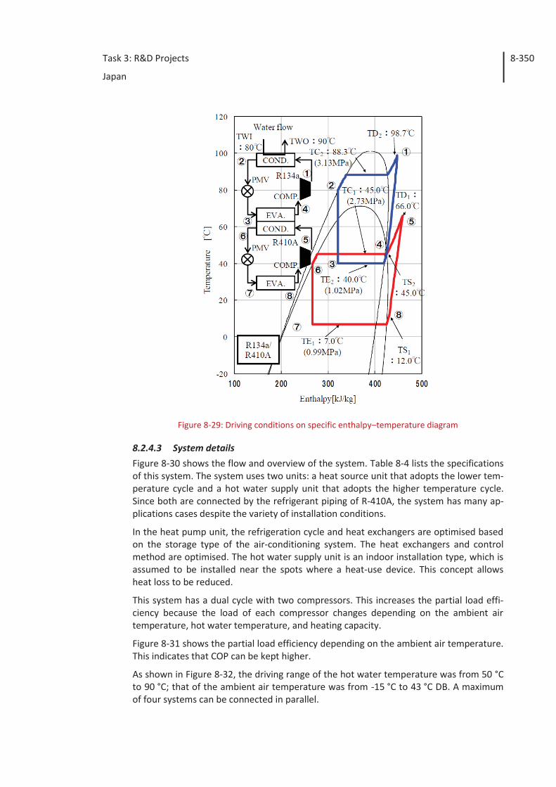
Task 3: R&D Projects
Japan
8-350
Figure 8-29: Driving conditions on specific enthalpy–temperature diagram
8.2.4.3 System details Figure 8-30 shows the flow and overview of the system. Table 8-4 lists the specifications of this system. The system uses two units: a heat source unit that adopts the lower tem-perature cycle and a hot water supply unit that adopts the higher temperature cycle. Since both are connected by the refrigerant piping of R-410A, the system has many ap-plications cases despite the variety of installation conditions.
In the heat pump unit, the refrigeration cycle and heat exchangers are optimised based on the storage type of the air-conditioning system. The heat exchangers and control method are optimised. The hot water supply unit is an indoor installation type, which is assumed to be installed near the spots where a heat-use device. This concept allows heat loss to be reduced.
This system has a dual cycle with two compressors. This increases the partial load effi-ciency because the load of each compressor changes depending on the ambient air temperature, hot water temperature, and heating capacity.
Figure 8-31 shows the partial load efficiency depending on the ambient air temperature. This indicates that COP can be kept higher.
As shown in Figure 8-32, the driving range of the hot water temperature was from 50 °C to 90 °C; that of the ambient air temperature was from -15 °C to 43 °C DB. A maximum of four systems can be connected in parallel.
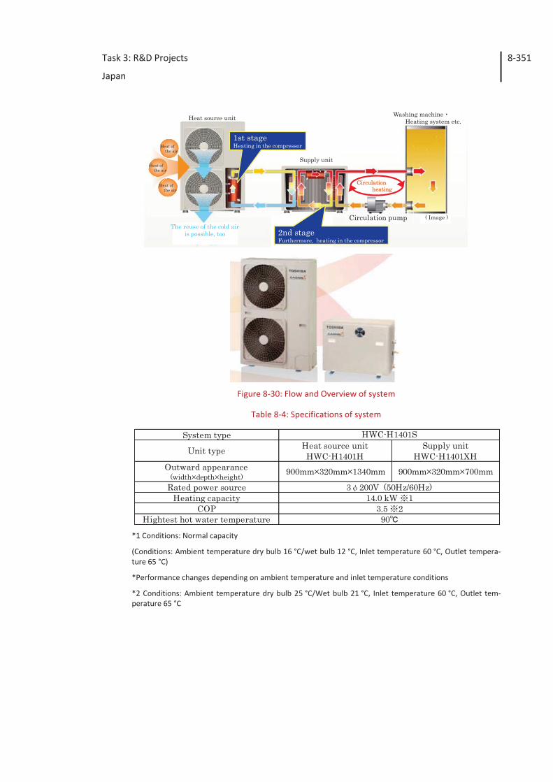
Task 3: R&D Projects
Japan
8-351
Figure 8-30: Flow and Overview of system
Table 8-4: Specifications of system
*1 Conditions: Normal capacity
(Conditions: Ambient temperature dry bulb 16 °C/wet bulb 12 °C, Inlet temperature 60 °C, Outlet tempera-ture 65 °C)
*Performance changes depending on ambient temperature and inlet temperature conditions
*2 Conditions: Ambient temperature dry bulb 25 °C/Wet bulb 21 °C, Inlet temperature 60 °C, Outlet tem-perature 65 °C
Supply unit
1st stageHeating in the compressor
2nd stageFurthermore, heating in the compressor
( Image )
Heat source unit
Circulation pump
Washing machine Heating system etc.
Circulation heating
Heat ofthe air
Heat ofthe air
Heat ofthe air
The reuse of the cold air is possible, too
System type
Unit type Heat source unitHWC-H1401H
Supply unitHWC-H1401XH
Outward appearance(width×depth×height) 900mm×320mm×1340mm 900mm×320mm×700mm
Rated power sourceHeating capacity
COPHightest hot water temperature 90
HWC-H1401S
3 200V (50Hz/60Hz)14.0 kW 1
3.5 2
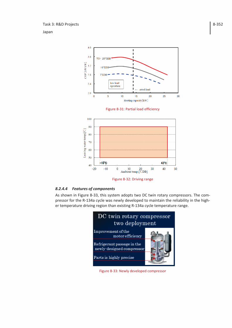
Task 3: R&D Projects
Japan
8-352
Figure 8-31: Partial load efficiency
Figure 8-32: Driving range
8.2.4.4 Features of components As shown in Figure 8-33, this system adopts two DC twin rotary compressors. The com-pressor for the R-134a cycle was newly developed to maintain the reliability in the high-er temperature driving region than existing R-134a cycle temperature range.
Figure 8-33: Newly developed compressor
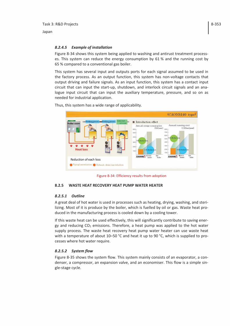
Task 3: R&D Projects
Japan
8-353
8.2.4.5 Example of installation Figure 8-34 shows this system being applied to washing and antirust treatment process-es. This system can reduce the energy consumption by 61 % and the running cost by 65 % compared to a conventional gas boiler.
This system has several input and outputs ports for each signal assumed to be used in the factory process. As an output function, this system has non-voltage contacts that output driving and failure signals. As an input function, this system has a contact input circuit that can input the start-up, shutdown, and interlock circuit signals and an ana-logue input circuit that can input the auxiliary temperature, pressure, and so on as needed for industrial application.
Thus, this system has a wide range of applicability.
Figure 8-34: Efficiency results from adoption
8.2.5 WASTE HEAT RECOVERY HEAT PUMP WATER HEATER
8.2.5.1 Outline A great deal of hot water is used in processes such as heating, drying, washing, and steri-lizing. Most of it is produce by the boiler, which is fuelled by oil or gas. Waste heat pro-duced in the manufacturing process is cooled down by a cooling tower.
If this waste heat can be used effectively, this will significantly contribute to saving ener-gy and reducing CO2 emissions. Therefore, a heat pump was applied to the hot water supply process. The waste heat recovery heat pump water heater can use waste heat with a temperature of about 10–50 °C and heat it up to 90 °C, which is supplied to pro-cesses where hot water require.
8.2.5.2 System flow Figure 8-35 shows the system flow. This system mainly consists of an evaporator, a con-denser, a compressor, an expansion valve, and an economiser. This flow is a simple sin-gle-stage cycle.
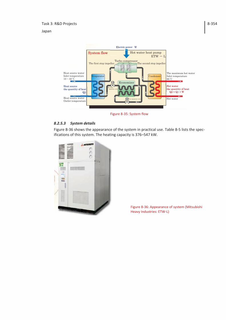
Task 3: R&D Projects
Japan
8-354
Figure 8-35: System flow
8.2.5.3 System details Figure 8-36 shows the appearance of the system in practical use. Table 8-5 lists the spec-ifications of this system. The heating capacity is 376–547 kW.
Figure 8-36: Appearance of system (Mitsubishi Heavy Industries: ETW-L)
System flow
Heat source waterOutlet temperature
Heat source waterInlet temperature10 ~ 50
Heat source the quantity of heat
Q1
The maximum hot waterInlet temperature90
Hot water
Hot waterthe quantity of heat
Q2 = Q1 + W
Electric power W
Economizer
Turbo compressor
Hot water heat pumpETW L
The mainexpansion valve
Vice-expansion valve
The first step impeller The second step impeller
Evaporator Condenser
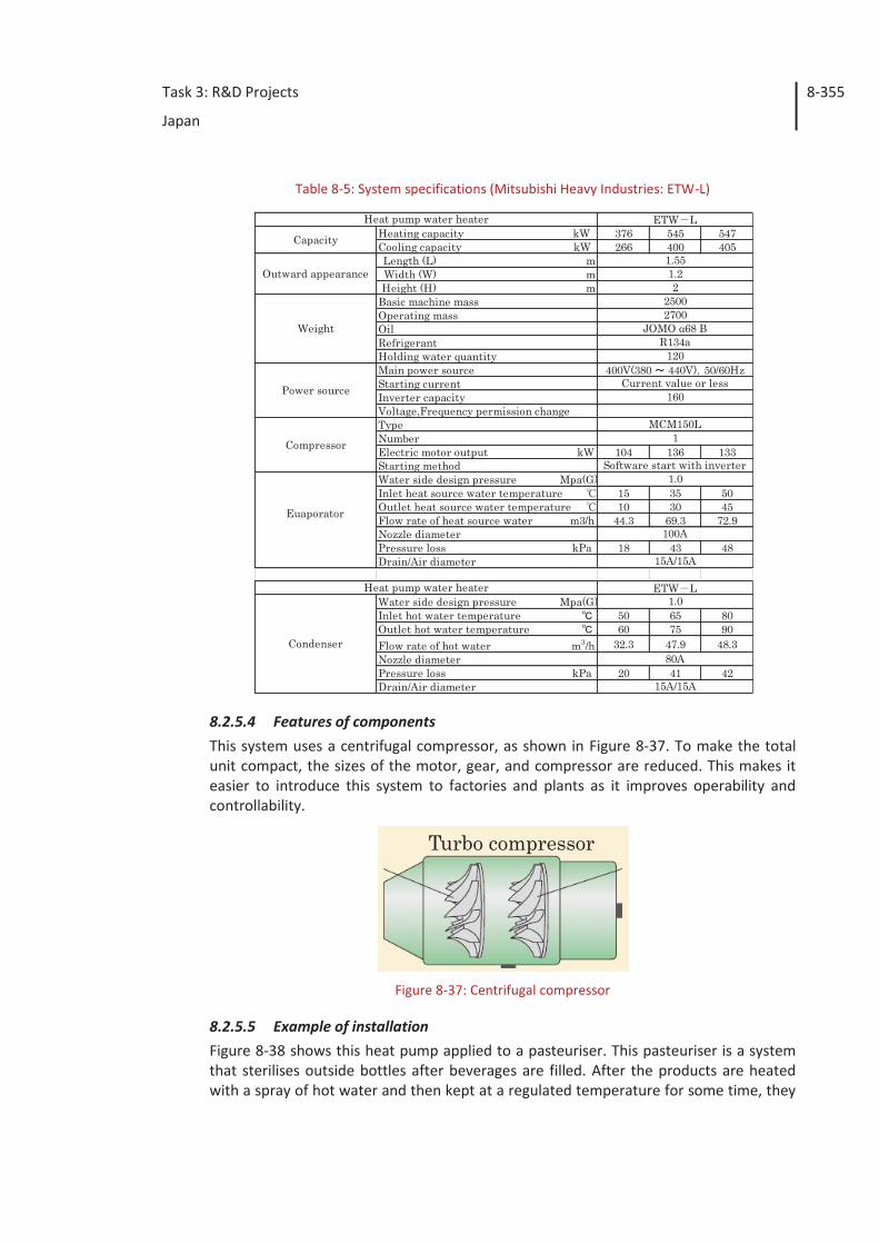
Task 3: R&D Projects
Japan
8-355
Table 8-5: System specifications (Mitsubishi Heavy Industries: ETW-L)
8.2.5.4 Features of components This system uses a centrifugal compressor, as shown in Figure 8-37. To make the total unit compact, the sizes of the motor, gear, and compressor are reduced. This makes it easier to introduce this system to factories and plants as it improves operability and controllability.
Figure 8-37: Centrifugal compressor
8.2.5.5 Example of installation Figure 8-38 shows this heat pump applied to a pasteuriser. This pasteuriser is a system that sterilises outside bottles after beverages are filled. After the products are heated with a spray of hot water and then kept at a regulated temperature for some time, they
Heating capacity kW 376 545 547Cooling capacity kW 266 400 405Length (L) mWidth (W) mHeight (H) m
Basic machine massOperating mass OilRefrigerantHolding water quantityMain power sourceStarting currentInverter capacityVoltage,Frequency permission changeTypeNumber Electric motor output kW 104 136 133Starting methodWater side design pressure Mpa(G)Inlet heat source water temperature 15 35 50Outlet heat source water temperature 10 30 45Flow rate of heat source water m3/h 44.3 69.3 72.9Nozzle diameterPressure loss kPa 18 43 48Drain/Air diameter
Water side design pressure Mpa(G)Inlet hot water temperature 50 65 80Outlet hot water temperature 60 75 90Flow rate of hot water m3/h 32.3 47.9 48.3Nozzle diameterPressure loss kPa 20 41 42Drain/Air diameter
ETW L
1.551.22
2500
Capacity
Outward appearance
Weight
Power source
Heat pump water heater
2700JOMO α68 B
R134a120
400V(380 440V) 50/60HzCurrent value or less
160
MCM150L1
80A
15A/15A
Condenser
Compressor
Euaporator
Software start with inverter1.0
100A
15A/15A
Heat pump water heater ETW L1.0
Turbo compressor
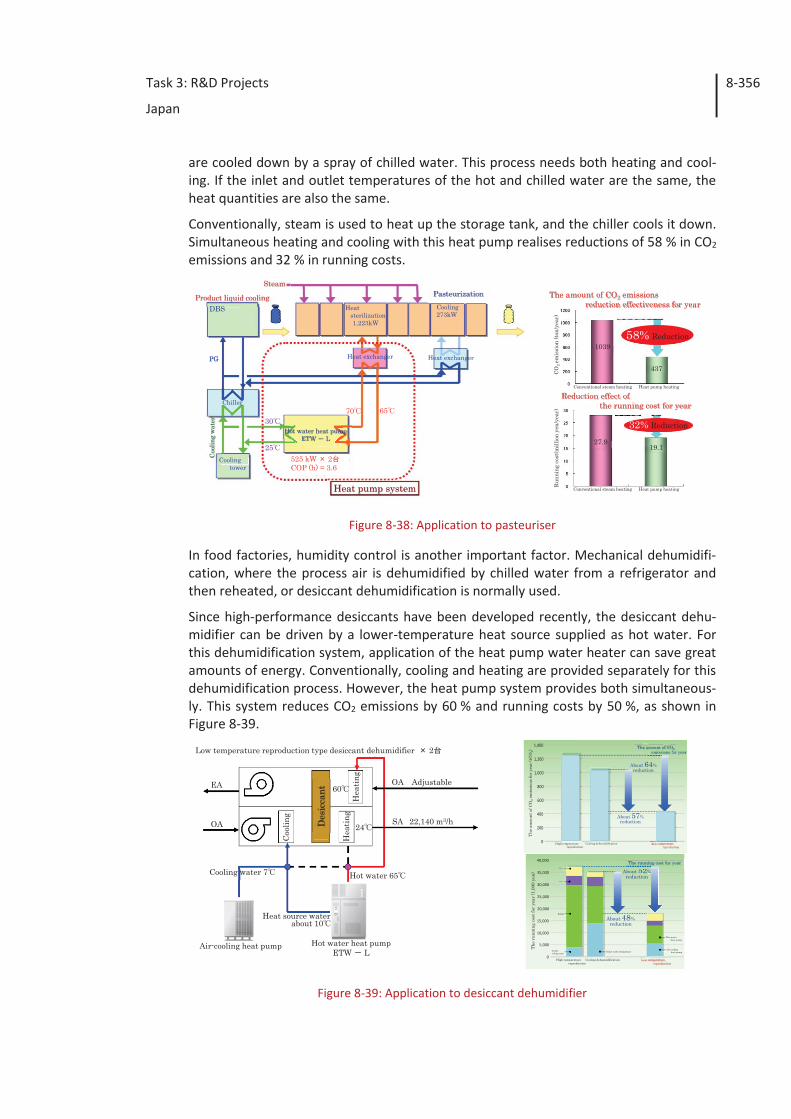
Task 3: R&D Projects
Japan
8-356
are cooled down by a spray of chilled water. This process needs both heating and cool-ing. If the inlet and outlet temperatures of the hot and chilled water are the same, the heat quantities are also the same.
Conventionally, steam is used to heat up the storage tank, and the chiller cools it down. Simultaneous heating and cooling with this heat pump realises reductions of 58 % in CO2 emissions and 32 % in running costs.
Figure 8-38: Application to pasteuriser
In food factories, humidity control is another important factor. Mechanical dehumidifi-cation, where the process air is dehumidified by chilled water from a refrigerator and then reheated, or desiccant dehumidification is normally used.
Since high-performance desiccants have been developed recently, the desiccant dehu-midifier can be driven by a lower-temperature heat source supplied as hot water. For this dehumidification system, application of the heat pump water heater can save great amounts of energy. Conventionally, cooling and heating are provided separately for this dehumidification process. However, the heat pump system provides both simultaneous-ly. This system reduces CO2 emissions by 60 % and running costs by 50 %, as shown in Figure 8-39.
Figure 8-39: Application to desiccant dehumidifier
Cooling273kW
Hot water heat pumpETW L
Coo
ling
wat
er
Coolingtower
Chiller
DBS
PG
30
25
70 65
525 kW 2COP (h) = 3.6
Heatsterilization1,223kW
Heat exchanger Heat exchanger
Heat pump system
Steam
DBSDBSProduct liquid cooling Pasteurization
58% Reduction
32% Reduction
CO2 em
issi
on (t
on/y
ear)
Runn
ing
cost
(mill
ion
yen/
year
)
Conventional steam heating Heat pump heating
Conventional steam heating Heat pump heating
1039
27.919.1
437
The amount of CO2 emissions reduction effectiveness for year
Conventional steam heatingen
Reduction effect of the running cost for year
OA Adjustable
SA 22,140 m3/h
Hot water 65Cooling water 7
Heat source waterabout 10
60
24
Coo
ling
Hea
ting
Hea
ting
Des
icca
nt
EA
OA
Hot water heat pumpETW L
Air-cooling heat pump
Low temperature reproduction type desiccant dehumidifier 2
40,000
35,000
30,000
25,000
20,000
15,000
10,000
0
5,000
High temperature reproduction
Cooling dehumidification Low temperaturereproduction
Hot waterheat pump
Air-coolingheat pump
H
Brine turbo refrigerator
Boiler
Turborefrigerator
***
***
About 48% reduction
About 52% reduction
The
runn
ing
cost
for
year
(1,0
00 y
en) 52
The running cost for year
1,400
1,200
1,000
800
600
400
200
0 High temperature reproduction
Cooling dehumidification Low temperaturereproduction
About 64% reduction
About 57% reduction
The
amou
nt o
f CO
2em
issi
ons
for
year
(tC
O2)
The amount of CO2emissions for year
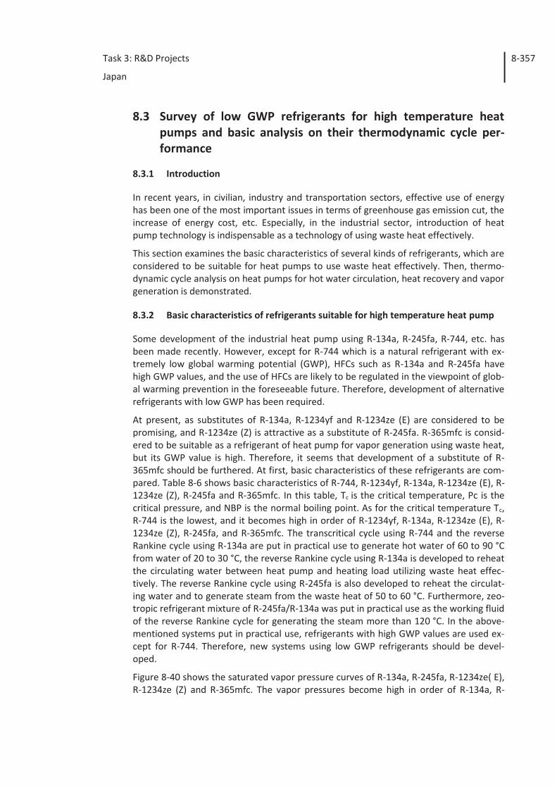
Task 3: R&D Projects
Japan
8-357
8.3 Survey of low GWP refrigerants for high temperature heat pumps and basic analysis on their thermodynamic cycle per-formance
8.3.1 Introduction
In recent years, in civilian, industry and transportation sectors, effective use of energy has been one of the most important issues in terms of greenhouse gas emission cut, the increase of energy cost, etc. Especially, in the industrial sector, introduction of heat pump technology is indispensable as a technology of using waste heat effectively.
This section examines the basic characteristics of several kinds of refrigerants, which are considered to be suitable for heat pumps to use waste heat effectively. Then, thermo-dynamic cycle analysis on heat pumps for hot water circulation, heat recovery and vapor generation is demonstrated.
8.3.2 Basic characteristics of refrigerants suitable for high temperature heat pump
Some development of the industrial heat pump using R-134a, R-245fa, R-744, etc. has been made recently. However, except for R-744 which is a natural refrigerant with ex-tremely low global warming potential (GWP), HFCs such as R-134a and R-245fa have high GWP values, and the use of HFCs are likely to be regulated in the viewpoint of glob-al warming prevention in the foreseeable future. Therefore, development of alternative refrigerants with low GWP has been required.
At present, as substitutes of R-134a, R-1234yf and R-1234ze (E) are considered to be promising, and R-1234ze (Z) is attractive as a substitute of R-245fa. R-365mfc is consid-ered to be suitable as a refrigerant of heat pump for vapor generation using waste heat, but its GWP value is high. Therefore, it seems that development of a substitute of R-365mfc should be furthered. At first, basic characteristics of these refrigerants are com-pared. Table 8-6 shows basic characteristics of R-744, R-1234yf, R-134a, R-1234ze (E), R-1234ze (Z), R-245fa and R-365mfc. In this table, Tc is the critical temperature, Pc is the critical pressure, and NBP is the normal boiling point. As for the critical temperature Tc, R-744 is the lowest, and it becomes high in order of R-1234yf, R-134a, R-1234ze (E), R-1234ze (Z), R-245fa, and R-365mfc. The transcritical cycle using R-744 and the reverse Rankine cycle using R-134a are put in practical use to generate hot water of 60 to 90 °C from water of 20 to 30 °C, the reverse Rankine cycle using R-134a is developed to reheat the circulating water between heat pump and heating load utilizing waste heat effec-tively. The reverse Rankine cycle using R-245fa is also developed to reheat the circulat-ing water and to generate steam from the waste heat of 50 to 60 °C. Furthermore, zeo-tropic refrigerant mixture of R-245fa/R-134a was put in practical use as the working fluid of the reverse Rankine cycle for generating the steam more than 120 °C. In the above-mentioned systems put in practical use, refrigerants with high GWP values are used ex-cept for R-744. Therefore, new systems using low GWP refrigerants should be devel-oped.
Figure 8-40 shows the saturated vapor pressure curves of R-134a, R-245fa, R-1234ze( E), R-1234ze (Z) and R-365mfc. The vapor pressures become high in order of R-134a, R-
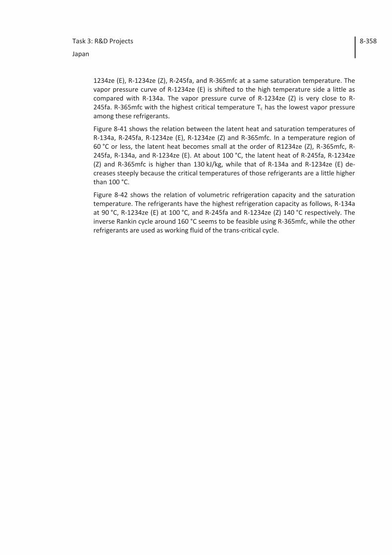
Task 3: R&D Projects
Japan
8-358
1234ze (E), R-1234ze (Z), R-245fa, and R-365mfc at a same saturation temperature. The vapor pressure curve of R-1234ze (E) is shifted to the high temperature side a little as compared with R-134a. The vapor pressure curve of R-1234ze (Z) is very close to R-245fa. R-365mfc with the highest critical temperature Tc has the lowest vapor pressure among these refrigerants.
Figure 8-41 shows the relation between the latent heat and saturation temperatures of R-134a, R-245fa, R-1234ze (E), R-1234ze (Z) and R-365mfc. In a temperature region of 60 °C or less, the latent heat becomes small at the order of R1234ze (Z), R-365mfc, R-245fa, R-134a, and R-1234ze (E). At about 100 °C, the latent heat of R-245fa, R-1234ze (Z) and R-365mfc is higher than 130 kJ/kg, while that of R-134a and R-1234ze (E) de-creases steeply because the critical temperatures of those refrigerants are a little higher than 100 °C.
Figure 8-42 shows the relation of volumetric refrigeration capacity and the saturation temperature. The refrigerants have the highest refrigeration capacity as follows, R-134a at 90 °C, R-1234ze (E) at 100 °C, and R-245fa and R-1234ze (Z) 140 °C respectively. The inverse Rankin cycle around 160 °C seems to be feasible using R-365mfc, while the other refrigerants are used as working fluid of the trans-critical cycle.
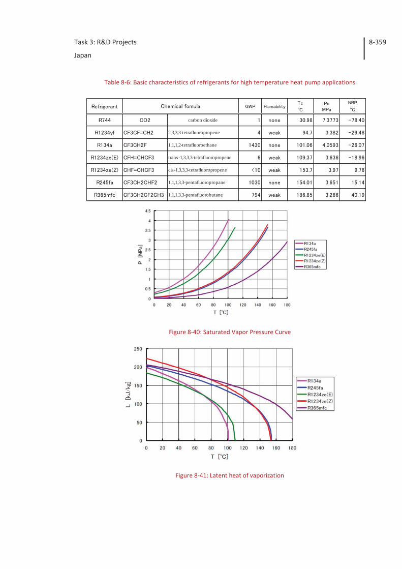
Task 3: R&D Projects
Japan
8-359
carbon dioxide
2,3,3,3-tetrafluoropropene
1,1,1,2-tetrafluoroethane
trans-1,3,3,3-tetrafluoropropene
cis-1,3,3,3-tetrafluoropropene
1,1,1,3,3-pentafluoropropane
1,1,1,3,3-pentafluorobutane
Table 8-6: Basic characteristics of refrigerants for high temperature heat pump applications
Figure 8-40: Saturated Vapor Pressure Curve
Figure 8-41: Latent heat of vaporization
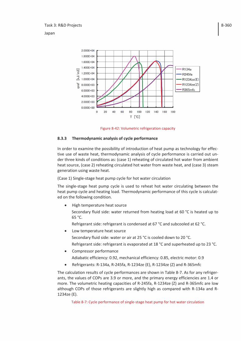
Task 3: R&D Projects
Japan
8-360
Figure 8-42: Volumetric refrigeration capacity
8.3.3 Thermodynamic analysis of cycle performance
In order to examine the possibility of introduction of heat pump as technology for effec-tive use of waste heat, thermodynamic analysis of cycle performance is carried out un-der three kinds of conditions as: (case 1) reheating of circulated hot water from ambient heat source, (case 2) reheating circulated hot water from waste heat, and (case 3) steam generation using waste heat.
(Case 1) Single-stage heat pump cycle for hot water circulation
The single-stage heat pump cycle is used to reheat hot water circulating between the heat pump cycle and heating load. Thermodynamic performance of this cycle is calculat-ed on the following condition.
High temperature heat source Secondary fluid side: water returned from heating load at 60 °C is heated up to 65 °C. Refrigerant side: refrigerant is condensed at 67 °C and subcooled at 62 °C.
Low temperature heat source Secondary fluid side: water or air at 25 °C is cooled down to 20 °C. Refrigerant side: refrigerant is evaporated at 18 °C and superheated up to 23 °C.
Compressor performance Adiabatic efficiency: 0.92, mechanical efficiency: 0.85, electric motor: 0.9
Refrigerants: R-134a, R-245fa, R-1234ze (E), R-1234ze (Z) and R-365mfc
The calculation results of cycle performances are shown in Table 8-7. As for any refriger-ants, the values of COPs are 3.9 or more, and the primary energy efficiencies are 1.4 or more. The volumetric heating capacities of R-245fa, R-1234ze (Z) and R-365mfc are low although COPs of those refrigerants are slightly high as compared with R-134a and R-1234ze (E).
Table 8-7: Cycle performance of single-stage heat pump for hot water circulation
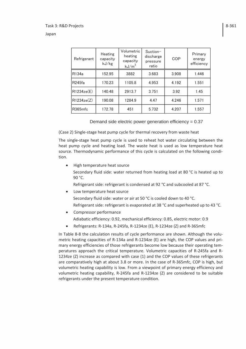
Task 3: R&D Projects
Japan
8-361
Demand side electric power generation efficiency = 0.37
(Case 2) Single-stage heat pump cycle for thermal recovery from waste heat
The single-stage heat pump cycle is used to reheat hot water circulating between the heat pump cycle and heating load. The waste heat is used as low temperature heat source. Thermodynamic performance of this cycle is calculated on the following condi-tion.
High temperature heat source Secondary fluid side: water returned from heating load at 80 °C is heated up to 90 °C. Refrigerant side: refrigerant is condensed at 92 °C and subcooled at 87 °C.
Low temperature heat source Secondary fluid side: water or air at 50 °C is cooled down to 40 °C. Refrigerant side: refrigerant is evaporated at 38 °C and superheated up to 43 °C.
Compressor performance Adiabatic efficiency: 0.92, mechanical efficiency: 0.85, electric motor: 0.9
Refrigerants: R-134a, R-245fa, R-1234ze (E), R-1234ze (Z) and R-365mfc
In Table 8-8 the calculation results of cycle performance are shown. Although the volu-metric heating capacities of R-134a and R-1234ze (E) are high, the COP values and pri-mary energy efficiencies of those refrigerants become low because their operating tem-peratures approach the critical temperature. Volumetric capacities of R-245fa and R-1234ze (Z) increase as compared with case (1) and the COP values of these refrigerants are comparatively high at about 3.8 or more. In the case of R-365mfc, COP is high, but volumetric heating capability is low. From a viewpoint of primary energy efficiency and volumetric heating capability, R-245fa and R-1234ze (Z) are considered to be suitable refrigerants under the present temperature condition.
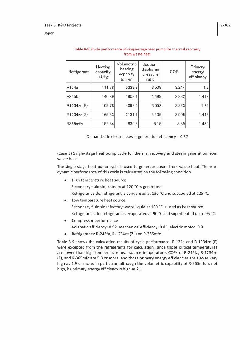
Task 3: R&D Projects
Japan
8-362
Table 8-8: Cycle performance of single-stage heat pump for thermal recovery from waste heat
Demand side electric power generation efficiency = 0.37
(Case 3) Single-stage heat pump cycle for thermal recovery and steam generation from waste heat
The single-stage heat pump cycle is used to generate steam from waste heat. Thermo-dynamic performance of this cycle is calculated on the following condition.
High temperature heat source Secondary fluid side: steam at 120 °C is generated Refrigerant side: refrigerant is condensed at 130 °C and subcooled at 125 °C.
Low temperature heat source Secondary fluid side: factory waste liquid at 100 °C is used as heat source Refrigerant side: refrigerant is evaporated at 90 °C and superheated up to 95 °C.
Compressor performance Adiabatic efficiency: 0.92, mechanical efficiency: 0.85, electric motor: 0.9
Refrigerants: R-245fa, R-1234ze (Z) and R-365mfc
Table 8-9 shows the calculation results of cycle performance. R-134a and R-1234ze (E) were excepted from the refrigerants for calculation, since those critical temperatures are lower than high temperature heat source temperature. COPs of R-245fa, R-1234ze (Z), and R-365mfc are 5.3 or more, and those primary energy efficiencies are also as very high as 1.9 or more. In particular, although the volumetric capability of R-365mfc is not high, its primary energy efficiency is high as 2.1.
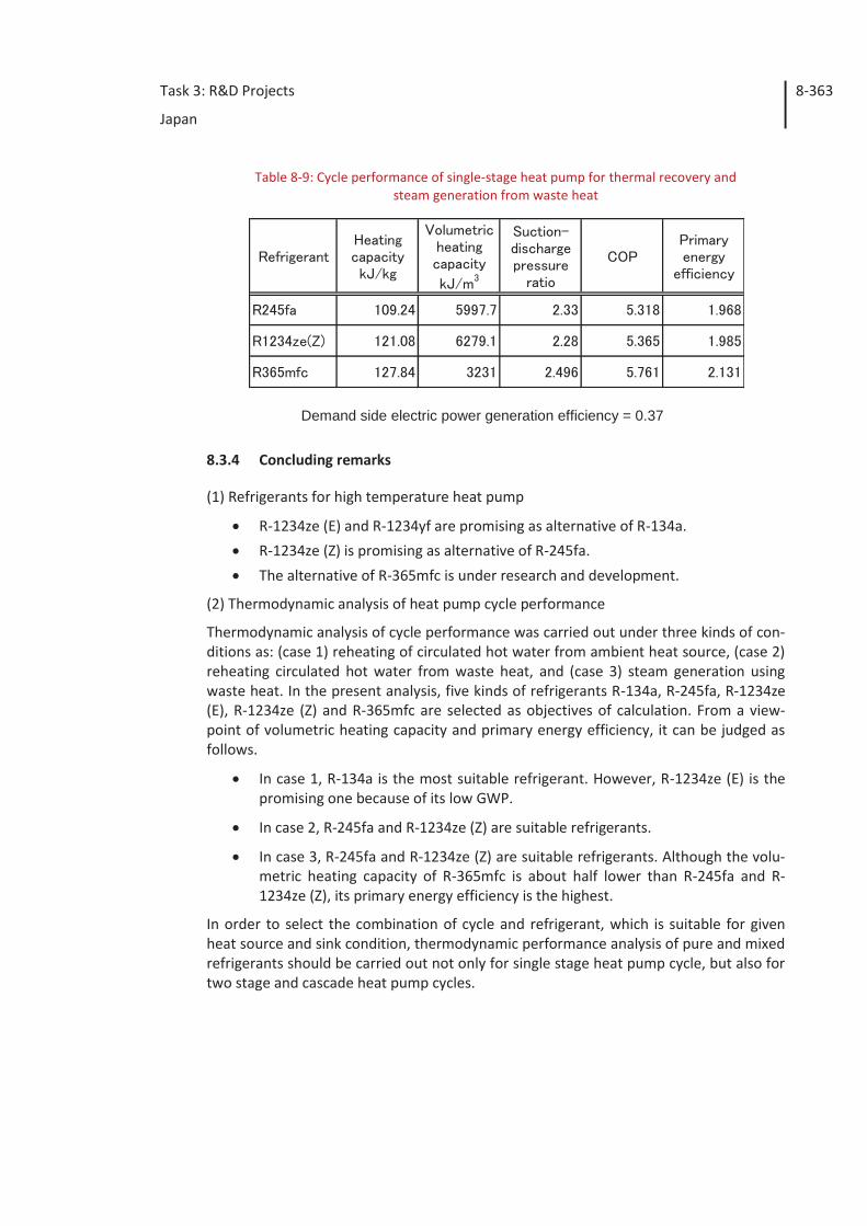
Task 3: R&D Projects
Japan
8-363
Table 8-9: Cycle performance of single-stage heat pump for thermal recovery and steam generation from waste heat
Demand side electric power generation efficiency = 0.37
8.3.4 Concluding remarks
(1) Refrigerants for high temperature heat pump
R-1234ze (E) and R-1234yf are promising as alternative of R-134a.
R-1234ze (Z) is promising as alternative of R-245fa.
The alternative of R-365mfc is under research and development.
(2) Thermodynamic analysis of heat pump cycle performance
Thermodynamic analysis of cycle performance was carried out under three kinds of con-ditions as: (case 1) reheating of circulated hot water from ambient heat source, (case 2) reheating circulated hot water from waste heat, and (case 3) steam generation using waste heat. In the present analysis, five kinds of refrigerants R-134a, R-245fa, R-1234ze (E), R-1234ze (Z) and R-365mfc are selected as objectives of calculation. From a view-point of volumetric heating capacity and primary energy efficiency, it can be judged as follows.
In case 1, R-134a is the most suitable refrigerant. However, R-1234ze (E) is the promising one because of its low GWP.
In case 2, R-245fa and R-1234ze (Z) are suitable refrigerants.
In case 3, R-245fa and R-1234ze (Z) are suitable refrigerants. Although the volu-metric heating capacity of R-365mfc is about half lower than R-245fa and R-1234ze (Z), its primary energy efficiency is the highest.
In order to select the combination of cycle and refrigerant, which is suitable for given heat source and sink condition, thermodynamic performance analysis of pure and mixed refrigerants should be carried out not only for single stage heat pump cycle, but also for two stage and cascade heat pump cycles.
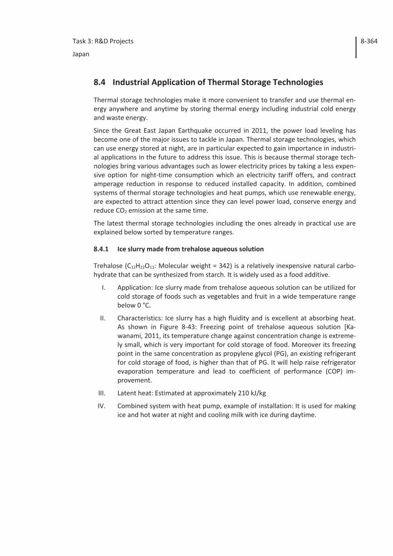
Task 3: R&D Projects
Japan
8-364
8.4 Industrial Application of Thermal Storage Technologies
Thermal storage technologies make it more convenient to transfer and use thermal en-ergy anywhere and anytime by storing thermal energy including industrial cold energy and waste energy.
Since the Great East Japan Earthquake occurred in 2011, the power load leveling has become one of the major issues to tackle in Japan. Thermal storage technologies, which can use energy stored at night, are in particular expected to gain importance in industri-al applications in the future to address this issue. This is because thermal storage tech-nologies bring various advantages such as lower electricity prices by taking a less expen-sive option for night-time consumption which an electricity tariff offers, and contract amperage reduction in response to reduced installed capacity. In addition, combined systems of thermal storage technologies and heat pumps, which use renewable energy, are expected to attract attention since they can level power load, conserve energy and reduce CO2 emission at the same time.
The latest thermal storage technologies including the ones already in practical use are explained below sorted by temperature ranges.
8.4.1 Ice slurry made from trehalose aqueous solution
Trehalose (C12H22O11: Molecular weight = 342) is a relatively inexpensive natural carbo-hydrate that can be synthesized from starch. It is widely used as a food additive.
I. Application: Ice slurry made from trehalose aqueous solution can be utilized for cold storage of foods such as vegetables and fruit in a wide temperature range below 0 °C.
II. Characteristics: Ice slurry has a high fluidity and is excellent at absorbing heat. As shown in Figure 8-43: Freezing point of trehalose aqueous solution [Ka-wanami, 2011, its temperature change against concentration change is extreme-ly small, which is very important for cold storage of food. Moreover its freezing point in the same concentration as propylene glycol (PG), an existing refrigerant for cold storage of food, is higher than that of PG. It will help raise refrigerator evaporation temperature and lead to coefficient of performance (COP) im-provement.
III. Latent heat: Estimated at approximately 210 kJ/kg
IV. Combined system with heat pump, example of installation: It is used for making ice and hot water at night and cooling milk with ice during daytime.
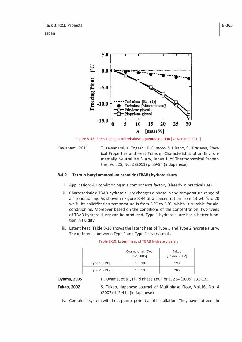
Task 3: R&D Projects
Japan
8-365
Figure 8-43: Freezing point of trehalose aqueous solution [Kawanami, 2011]
Kawanami, 2011 T. Kawanami, K. Togashi, K. Fumoto, S. Hirano, S. Hirasawa, Phys-ical Properties and Heat Transfer Characteristics of an Environ-mentally Neutral Ice Slurry, Japan J. of Thermophysical Proper-ties, Vol. 25, No. 2 (2011) p. 89-94 (in Japanese)
8.4.2 Tetra-n-butyl ammonium bromide (TBAB) hydrate slurry
i. Application: Air conditioning at a components factory (already in practical use)
ii. Characteristics: TBAB hydrate slurry changes a phase in the temperature range of air conditioning. As shown in Figure 8-44 at a concentration from 13 wt. to 20 wt. , its solidification temperature is from 5 °C to 8 °C, which is suitable for air-conditioning. Moreover based on the conditions of the concentration, two types of TBAB hydrate slurry can be produced. Type 1 hydrate slurry has a better func-tion in fluidity.
iii. Latent heat: Table 8-10 shows the latent heat of Type 1 and Type 2 hydrate slurry. The difference between Type 1 and Type 2 is very small.
Table 8-10: Latent heat of TBAB hydrate crystals
Oyama et al. [Oya-ma,2005]
Takao [Takao, 2002]
Type 1 (kJ/kg) 193.18 193
Type 2 (kJ/kg) 199.59 205
Oyama, 2005 H. Oyama, et al., Fluid Phase Equilibria, 234 (2005) 131-135
Takao, 2002 S. Takao Japanese Journal of Multiphase Flow, Vol.16, No. 4 (2002) 412-414 (in Japanese)
iv. Combined system with heat pump, potential of installation: They have not been in
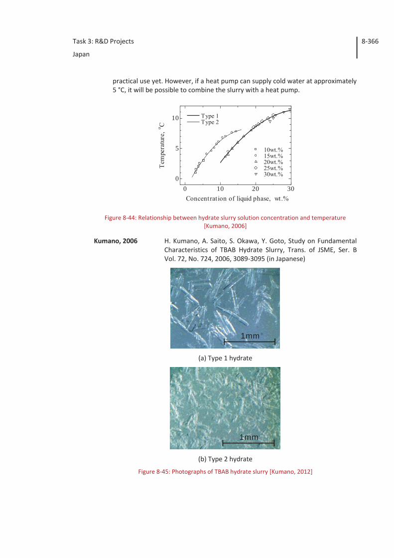
Task 3: R&D Projects
Japan
8-366
practical use yet. However, if a heat pump can supply cold water at approximately 5 °C, it will be possible to combine the slurry with a heat pump.
Figure 8-44: Relationship between hydrate slurry solution concentration and temperature [Kumano, 2006]
Kumano, 2006 H. Kumano, A. Saito, S. Okawa, Y. Goto, Study on Fundamental Characteristics of TBAB Hydrate Slurry, Trans. of JSME, Ser. B Vol. 72, No. 724, 2006, 3089-3095 (in Japanese)
1mm
(a) Type 1 hydrate
1mm
(b) Type 2 hydrate
Figure 8-45: Photographs of TBAB hydrate slurry [Kumano, 2012]
0 10 20 300
5
10
Concentration of liquid phase, wt.%
Tem
pera
ture
, o C
10wt.% 15wt.% 20wt.% 25wt.% 30wt.%
Type 1 Type 2
Task 3: R&D Projects
Japan
8-367
Kumano, 2012 H. Kumano, T. Hirata, Y. Hagiwara, F. Tamura, Effects of Storage on Flow and Heat Transfer Characteristics of Ice Slurry, Int. Jour-nal of Refrigeration, Vol. 35, No. 1, 2012, 122-129
8.4.3 Paraffin slurry
(a) Ice slurry: produced by nanoemulsion with water as a continuous phase and tetrade-cane as a dispersed phase.
i. Application: Air conditioning at factories
ii. Characteristics: Paraffin slurry has fluidity and changes a phase at around 5.9 °C, which is very suitable for air conditioning. Table 8-11 shows the physical proper-ties of tetradecane and Table 8-12 shows the nanoemulsion composition ratio. As shown in Table 8-12, two types of non-ionic surfactant (Span 80, Tween 120) are mixed for the emulsion.
iii. Latent heat: Table 8-13 shows the thermophysical properties of the nanoemul-sion.
iv. Combined system with heat pump, example of installation: They have not been in practical use yet.
Table 8-11: Physical properties of tetradecane [Fumoto, 2011]
Properties Tetradecane
Melting point (°C) 5.9
Latent heat (kJ/kg) 229.1
Specific heat (kJ/(kg K)) 1.80 (Solid), 2.14 (Liquid)
Density (kg/m3) 810 (Solid), 770 (Liquid)
Viscosity (mPa s) 2.47
Table 8-12: Composition ratio of nanoemulsion [Fumoto, 2011]
Tetradecane (wt%) Surfactant (Span 80, Tween 120) (wt%)
Water (wt%)
10.0 8.0 82.0
20.0 8.0 72.0
Table 8-13: Thermophysical properties of nanoemulsion [Fumoto, 2011]
Fumoto, 2011 K. Fumoto, M. Kawaji, T. Kawanami, Thermophysical Property
Measurements of Tetradecane Nanoemulsion Density and
Tetradecane (wt%) Thermal conductivity W/(m K) Viscosity (mPa s)
10.0 0.578 (at 28.1°C) 2.16
20.0 3.24
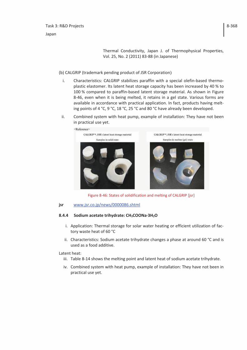
Task 3: R&D Projects
Japan
8-368
Thermal Conductivity, Japan J. of Thermophysical Properties, Vol. 25, No. 2 (2011) 83-88 (in Japanese)
(b) CALGRIP (trademark pending product of JSR Corporation)
i. Characteristics: CALGRIP stabilizes paraffin with a special olefin-based thermo-plastic elastomer. Its latent heat storage capacity has been increased by 40 % to 100 % compared to paraffin-based latent storage material. As shown in Figure 8-46, even when it is being melted, it retains in a gel state. Various forms are available in accordance with practical application. In fact, products having melt-ing points of 4 °C, 9 °C, 18 °C, 25 °C and 80 °C have already been developed.
ii. Combined system with heat pump, example of installation: They have not been in practical use yet.
Figure 8-46: States of solidification and melting of CALGRIP [jsr]
jsr www.jsr.co.jp/news/0000086.shtml
8.4.4 Sodium acetate trihydrate: CH3COONa·3H2O
i. Application: Thermal storage for solar water heating or efficient utilization of fac-tory waste heat of 60 °C
ii. Characteristics: Sodium acetate trihydrate changes a phase at around 60 °C and is used as a food additive.
Latent heat: iii. Table 8-14 shows the melting point and latent heat of sodium acetate trihydrate.
iv. Combined system with heat pump, example of installation: They have not been in practical use yet.
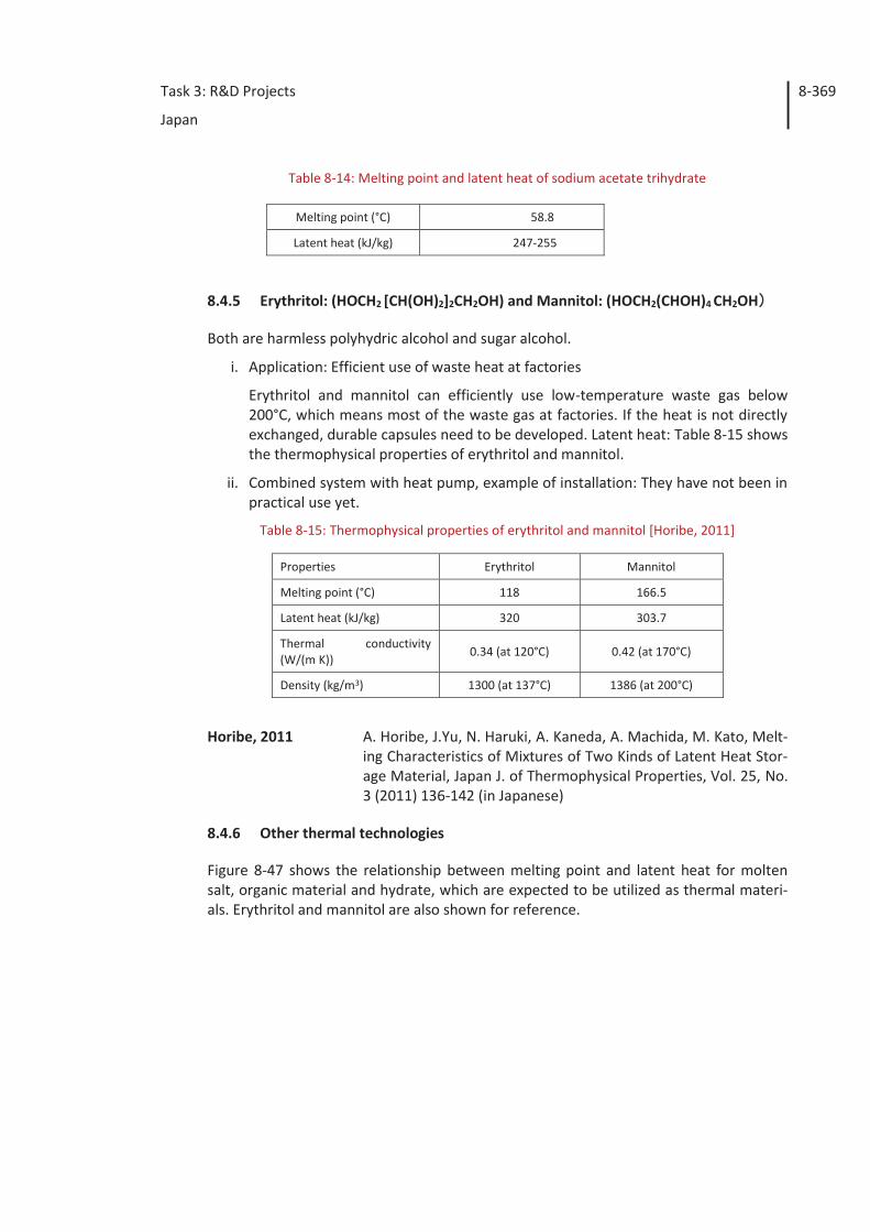
Task 3: R&D Projects
Japan
8-369
Table 8-14: Melting point and latent heat of sodium acetate trihydrate
8.4.5 Erythritol: (HOCH2 [CH(OH)2]2CH2OH) and Mannitol: (HOCH2(CHOH)4 CH2OH
Both are harmless polyhydric alcohol and sugar alcohol.
i. Application: Efficient use of waste heat at factories
Erythritol and mannitol can efficiently use low-temperature waste gas below 200°C, which means most of the waste gas at factories. If the heat is not directly exchanged, durable capsules need to be developed. Latent heat: Table 8-15 shows the thermophysical properties of erythritol and mannitol.
ii. Combined system with heat pump, example of installation: They have not been in practical use yet.
Table 8-15: Thermophysical properties of erythritol and mannitol [Horibe, 2011]
Properties Erythritol Mannitol
Melting point (°C) 118 166.5
Latent heat (kJ/kg) 320 303.7
Thermal conductivity (W/(m K))
0.34 (at 120°C) 0.42 (at 170°C)
Density (kg/m3) 1300 (at 137°C) 1386 (at 200°C)
Horibe, 2011 A. Horibe, J.Yu, N. Haruki, A. Kaneda, A. Machida, M. Kato, Melt-ing Characteristics of Mixtures of Two Kinds of Latent Heat Stor-age Material, Japan J. of Thermophysical Properties, Vol. 25, No. 3 (2011) 136-142 (in Japanese)
8.4.6 Other thermal technologies
Figure 8-47 shows the relationship between melting point and latent heat for molten salt, organic material and hydrate, which are expected to be utilized as thermal materi-als. Erythritol and mannitol are also shown for reference.
Melting point (°C) 58.8
Latent heat (kJ/kg) 247-255
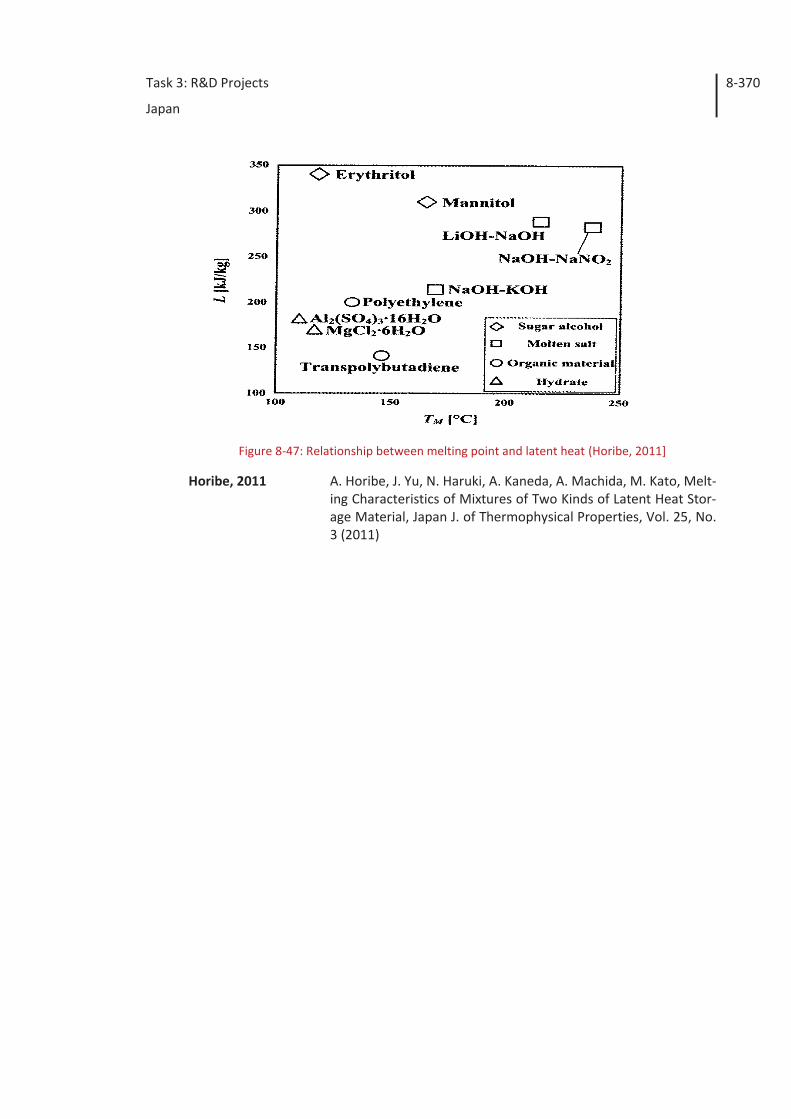
Task 3: R&D Projects
Japan
8-370
Figure 8-47: Relationship between melting point and latent heat (Horibe, 2011]
Horibe, 2011 A. Horibe, J. Yu, N. Haruki, A. Kaneda, A. Machida, M. Kato, Melt-ing Characteristics of Mixtures of Two Kinds of Latent Heat Stor-age Material, Japan J. of Thermophysical Properties, Vol. 25, No. 3 (2011)
Task 3: R&D Projects
Korea
9-371
9 Korea
9.1 R&D Background of industrial heat pumps
More than 60 % of the total energy is consumed for the industrial application in Korea. A great portion of final energy in industrial field is to generate heat or provided as feed-stock. So, a lot of activities have been done to improve efficiency or make advanced process in order to reduce primary energy consumption and green gas emission. The major directions of such activities are;
- Utilization of waste heat from industrial processes (reduce green gas emission and production cost) by hybridized heat source with renewables
- Production of hot water which can be directly used to the processes
- Extension of heat pump applications into advanced industrial processes formerly ne-glected to be a part of the processes
Under these circumstances, the application of industrial heat pump has gained much interest in these days by not only companies but also government agents.
The global heat pump market has been increased rapidly. More interest has been given to energy efficiency increase as one of the solution to urgent problems of energy cost and environmental effect. So far, the main fields of heat pump market have been heat-ing/cooling system and hot water generation system. Therefore the researches and poli-cies of government have been focused on these topics. It is true that the interest on industrial heat pump featuring high temperature operation range has gained relatively low interest. Furthermore, the retail energy prices of Korea have been maintained at low level. This makes the manufacturers less sensitive to the energy cost of the product. So the manufacturers pose inactive stance on the investment of energy efficiency facili-ties rather than productivity increase facilities.
There are well established test standards and installation guides for the heat pump for heating and cooling. And major manufacturers dominate that market with well-modularized, mass-produced products. However, the install scene for industrial heat pump has its unique requirements. So, system design and installation should be done to cover these things. It is true that industrial heat pump has weak points in standardiza-tion and mass production. This, further makes not only the manufacturers, but also in-staller and engineers to have much higher technical level ever before.
Despite of all of these adverse features of industrial heat pump, the confronting issues like global warming, the climate change convention, surging of energy prices, depletion of fossil fuel, and so on, have changed the working situation in industrial market, and the manufacturers have begun to consider adopting devices or facilities which are envi-ronmentally benign requiring less primary energy. Industrial heat pump has become one of the best solutions for the manufacturers.
The benefits of adopting heat pump in industrial process are
- Heat pump is one of the most optimum solutions to recycle waste heat of industrial processes
Task 3: R&D Projects
Korea
9-372
- Application of industrial heat pump can contribute to the reduction in green gas emission
- Since heat pump can use energy from air, sea water, underground water, or any oth-er low temperature heat resources, the additional heat out of the total produced heat is classified as renewable energy
In the Korean hot water heat pump market, 50-60 °C hot water generation systems oc-cupy most of the market share. In order to be applied to industrial process, the genera-tion temperature should be increased up to 90 °C or above. And since heat pump sys-tems also produce chilled water while producing hot water owing to their thermody-namic nature, process design considering both heating and cooling resources is required to maximize energy savings with heat pump. The concept of energy network has risen under this circumstance.
9.2 R&D programs of Korea
Energy R&D in Korea is supported largely by the Ministry of Trade, Industry and Energy (MOTIE). As a key operating agent, Korea Institute of Energy Technology Evaluation and Planning (KETEP) is running four major categories of Energy Efficiency and Resource Program, New and Renewable Energy Program, Power and Electricity Technology Pro-gram, Nuclear Power Program.
Heat pump R&D in Korea is categorized into Energy Efficiency and Resources Program. The scope of the program is to ensure effective accomplishment of the objectives of the governments Framework Plan for the Development of Energy and Resource Technolo-gies for the Years 2006-2015, where key parts are energy storage, heat pumps, micro CHP, building energy, green cars, clean fuel, energy equipment, industrial process, CCS, and energy resources.
Heat pump technologies were categorized in the national roadmaps in Korea listed be-low.
- Environmental Energy Core Technology in National Technical Roadmap (NTRM) (2002)
- Environmental Energy Area in Innovative Technology Five-Year Master Plan (2004)
- Energy Efficient Technology of Unutilized Energy Applications in Energy Technology Ten-Year Roadmap by the Ministry of Commerce, Industry and Energy (MOCIE, a former MOTIE) (2004)
- The Seven-Runners Program for massive energy consuming equipment by MOCIE (2006)
- Korean National Green Energy Strategic Roadmap by MOTIE
1st roadmap (2009)
Solar power, Wind power, Fuel cell, IGCC, CCS, Energy stor-age, Electric power-IT convergence, LED, Nuclear power, Mi-cro CHP, Green car, Superconductivity, Heat pump, Building
energy
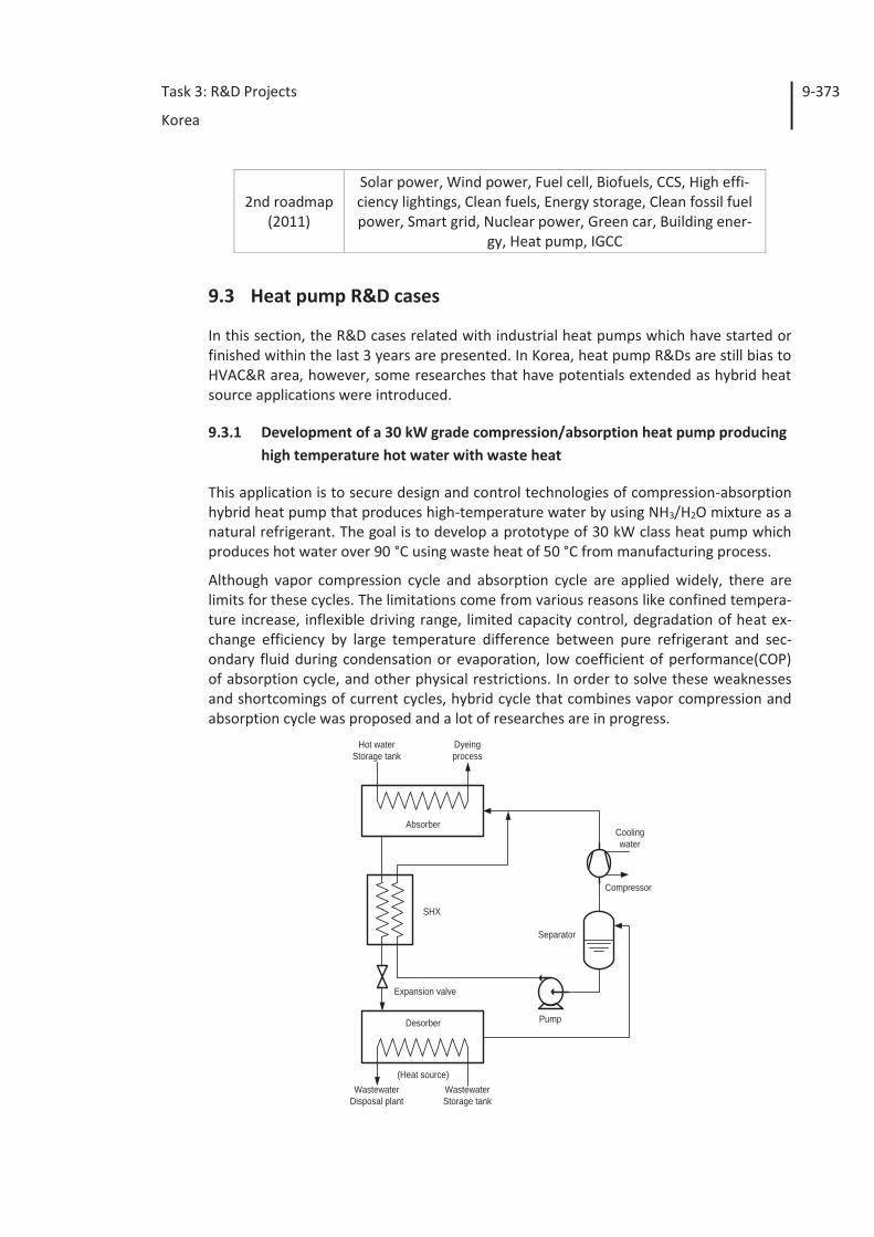
Task 3: R&D Projects
Korea
9-373
2nd roadmap (2011)
Solar power, Wind power, Fuel cell, Biofuels, CCS, High effi-ciency lightings, Clean fuels, Energy storage, Clean fossil fuel power, Smart grid, Nuclear power, Green car, Building ener-
gy, Heat pump, IGCC
9.3 Heat pump R&D cases
In this section, the R&D cases related with industrial heat pumps which have started or finished within the last 3 years are presented. In Korea, heat pump R&Ds are still bias to HVAC&R area, however, some researches that have potentials extended as hybrid heat source applications were introduced.
9.3.1 Development of a 30 kW grade compression/absorption heat pump producing high temperature hot water with waste heat
This application is to secure design and control technologies of compression-absorption hybrid heat pump that produces high-temperature water by using NH3/H2O mixture as a natural refrigerant. The goal is to develop a prototype of 30 kW class heat pump which produces hot water over 90 °C using waste heat of 50 °C from manufacturing process.
Although vapor compression cycle and absorption cycle are applied widely, there are limits for these cycles. The limitations come from various reasons like confined tempera-ture increase, inflexible driving range, limited capacity control, degradation of heat ex-change efficiency by large temperature difference between pure refrigerant and sec-ondary fluid during condensation or evaporation, low coefficient of performance(COP) of absorption cycle, and other physical restrictions. In order to solve these weaknesses and shortcomings of current cycles, hybrid cycle that combines vapor compression and absorption cycle was proposed and a lot of researches are in progress.
Absorber
Desorber
(Heat source)Wastewater
Disposal plantWastewaterStorage tank
SHX
Expansion valve
Pump
Compressor
Coolingwater
Hot waterStorage tank
Dyeingprocess
Separator
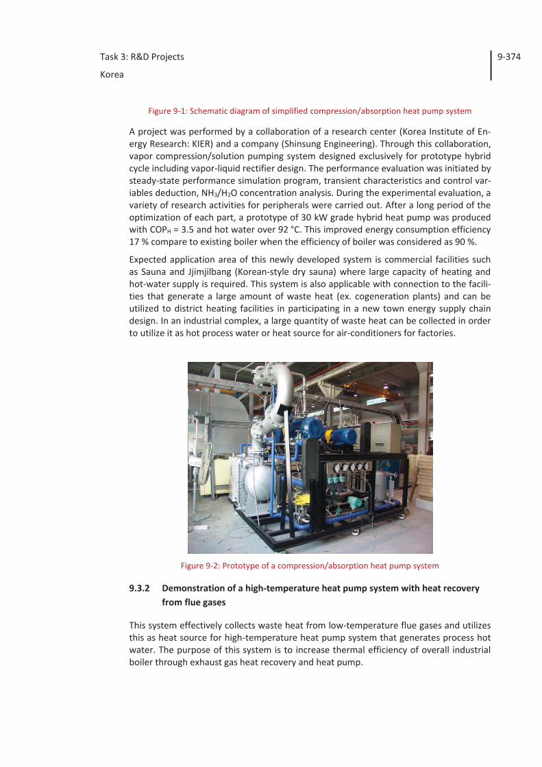
Task 3: R&D Projects
Korea
9-374
Figure 9-1: Schematic diagram of simplified compression/absorption heat pump system
A project was performed by a collaboration of a research center (Korea Institute of En-ergy Research: KIER) and a company (Shinsung Engineering). Through this collaboration, vapor compression/solution pumping system designed exclusively for prototype hybrid cycle including vapor-liquid rectifier design. The performance evaluation was initiated by steady-state performance simulation program, transient characteristics and control var-iables deduction, NH3/H2O concentration analysis. During the experimental evaluation, a variety of research activities for peripherals were carried out. After a long period of the optimization of each part, a prototype of 30 kW grade hybrid heat pump was produced with COPH = 3.5 and hot water over 92 °C. This improved energy consumption efficiency 17 % compare to existing boiler when the efficiency of boiler was considered as 90 %.
Expected application area of this newly developed system is commercial facilities such as Sauna and Jjimjilbang (Korean-style dry sauna) where large capacity of heating and hot-water supply is required. This system is also applicable with connection to the facili-ties that generate a large amount of waste heat (ex. cogeneration plants) and can be utilized to district heating facilities in participating in a new town energy supply chain design. In an industrial complex, a large quantity of waste heat can be collected in order to utilize it as hot process water or heat source for air-conditioners for factories.
Figure 9-2: Prototype of a compression/absorption heat pump system
9.3.2 Demonstration of a high-temperature heat pump system with heat recovery from flue gases
This system effectively collects waste heat from low-temperature flue gases and utilizes this as heat source for high-temperature heat pump system that generates process hot water. The purpose of this system is to increase thermal efficiency of overall industrial boiler through exhaust gas heat recovery and heat pump.
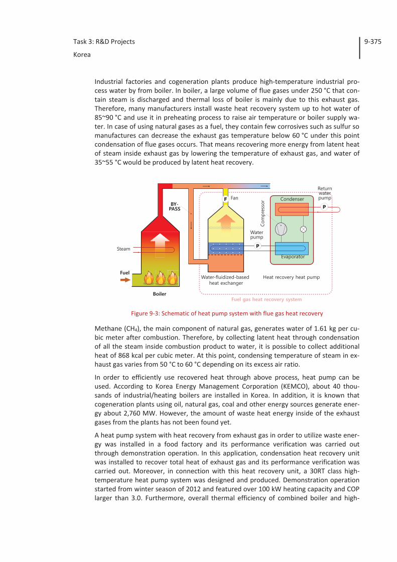
Task 3: R&D Projects
Korea
9-375
Industrial factories and cogeneration plants produce high-temperature industrial pro-cess water by from boiler. In boiler, a large volume of flue gases under 250 °C that con-tain steam is discharged and thermal loss of boiler is mainly due to this exhaust gas. Therefore, many manufacturers install waste heat recovery system up to hot water of 85~90 °C and use it in preheating process to raise air temperature or boiler supply wa-ter. In case of using natural gases as a fuel, they contain few corrosives such as sulfur so manufactures can decrease the exhaust gas temperature below 60 °C under this point condensation of flue gases occurs. That means recovering more energy from latent heat of steam inside exhaust gas by lowering the temperature of exhaust gas, and water of 35~55 °C would be produced by latent heat recovery.
Figure 9-3: Schematic of heat pump system with flue gas heat recovery
Methane (CH4), the main component of natural gas, generates water of 1.61 kg per cu-bic meter after combustion. Therefore, by collecting latent heat through condensation of all the steam inside combustion product to water, it is possible to collect additional heat of 868 kcal per cubic meter. At this point, condensing temperature of steam in ex-haust gas varies from 50 °C to 60 °C depending on its excess air ratio.
In order to efficiently use recovered heat through above process, heat pump can be used. According to Korea Energy Management Corporation (KEMCO), about 40 thou-sands of industrial/heating boilers are installed in Korea. In addition, it is known that cogeneration plants using oil, natural gas, coal and other energy sources generate ener-gy about 2,760 MW. However, the amount of waste heat energy inside of the exhaust gases from the plants has not been found yet.
A heat pump system with heat recovery from exhaust gas in order to utilize waste ener-gy was installed in a food factory and its performance verification was carried out through demonstration operation. In this application, condensation heat recovery unit was installed to recover total heat of exhaust gas and its performance verification was carried out. Moreover, in connection with this heat recovery unit, a 30RT class high-temperature heat pump system was designed and produced. Demonstration operation started from winter season of 2012 and featured over 100 kW heating capacity and COP larger than 3.0. Furthermore, overall thermal efficiency of combined boiler and high-
P
FP
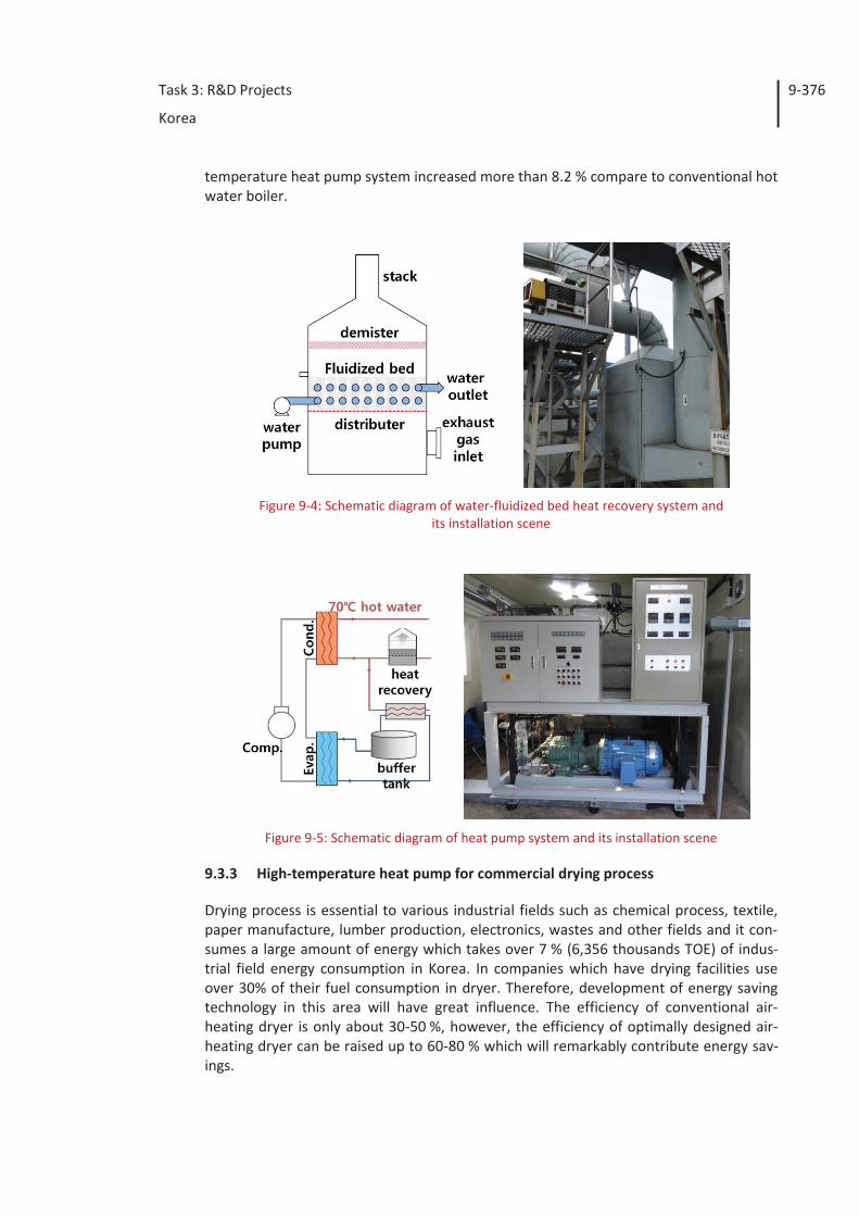
Task 3: R&D Projects
Korea
9-376
temperature heat pump system increased more than 8.2 % compare to conventional hot water boiler.
Figure 9-4: Schematic diagram of water-fluidized bed heat recovery system and its installation scene
Figure 9-5: Schematic diagram of heat pump system and its installation scene
9.3.3 High-temperature heat pump for commercial drying process
Drying process is essential to various industrial fields such as chemical process, textile, paper manufacture, lumber production, electronics, wastes and other fields and it con-sumes a large amount of energy which takes over 7 % (6,356 thousands TOE) of indus-trial field energy consumption in Korea. In companies which have drying facilities use over 30% of their fuel consumption in dryer. Therefore, development of energy saving technology in this area will have great influence. The efficiency of conventional air-heating dryer is only about 30-50 %, however, the efficiency of optimally designed air-heating dryer can be raised up to 60-80 % which will remarkably contribute energy sav-ings.
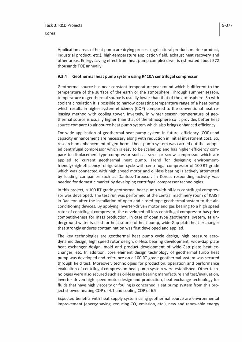
Task 3: R&D Projects
Korea
9-377
Application areas of heat pump are drying process (agricultural product, marine product, industrial product, etc.), high-temperature application field, exhaust heat recovery and other areas. Energy saving effect from heat pump complex dryer is estimated about 572 thousands TOE annually.
9.3.4 Geothermal heat pump system using R410A centrifugal compressor
Geothermal source has near constant temperature year-round which is different to the temperature of the surface of the earth or the atmosphere. Through summer season, temperature of geothermal source is usually lower than that of the atmosphere. So with coolant circulation it is possible to narrow operating temperature range of a heat pump which results in higher system efficiency (COP) compared to the conventional heat re-leasing method with cooling tower. Inversely, in winter season, temperature of geo-thermal source is usually higher than that of the atmosphere so it provides better heat source compare to air-source heat pump system which also brings enhanced efficiency.
For wide application of geothermal heat pump system in future, efficiency (COP) and capacity enhancement are necessary along with reduction in initial investment cost. So, research on enhancement of geothermal heat pump system was carried out that adopt-ed centrifugal compressor which is easy to be scaled up and has higher efficiency com-pare to displacement-type compressor such as scroll or screw compressor which are applied to current geothermal heat pump. Trend for designing environment-friendly/high-efficiency refrigeration cycle with centrifugal compressor of 100 RT grade which was connected with high speed motor and oil-less bearing is actively attempted by leading companies such as Danfoss-Turbocor. In Korea, responding activity was needed for domestic market by developing centrifugal compressor technologies.
In this project, a 100 RT grade geothermal heat pump with oil-less centrifugal compres-sor was developed. The test run was performed at the central machinery room of KAIST in Daejeon after the installation of open and closed type geothermal system to the air-conditioning devices. By applying inverter-driven motor and gas bearing to a high speed rotor of centrifugal compressor, the developed oil-less centrifugal compressor has price competitiveness for mass production. In case of open type geothermal system, as un-derground water is used for heat source of heat pump, wide-Gap plate heat exchanger that strongly endures contamination was first developed and applied.
The key technologies are geothermal heat pump cycle design, high pressure aero-dynamic design, high speed rotor design, oil-less bearing development, wide-Gap plate heat exchanger design, mold and product development of wide-Gap plate heat ex-changer, etc. In addition, core element design technology of geothermal turbo heat pump was developed and reference on a 100 RT grade geothermal system was secured through field test. Moreover, technologies for production, operation and performance evaluation of centrifugal compression heat pump system were established. Other tech-nologies were also secured such as oil-less gas bearing manufacture and test/evaluation, inverter-driven high speed motor design and production, heat exchange technology for fluids that have high viscosity or fouling is concerned. Heat pump system from this pro-ject showed heating COP of 4.1 and cooling COP of 6.9.
Expected benefits with heat supply system using geothermal source are environmental improvement (energy saving, reducing CO2 emission, etc.), new and renewable energy
Task 3: R&D Projects
Korea
9-378
utilization and so on. Because of those positive effects, this system is applicable to air-conditioning system for building and green house complex air-conditioning and heat supply. A 100RT grade heat pump unit with centrifugal compression technology is ex-pected to be highly competitive where screw compressor types are currently dominant in the market. Moreover, by developing wide-gap plate heat exchanger technology, it will be simple to use underground water, high viscosity fluid or highly contaminated heat source directly.
With this improved efficiency of heat pump system, payback period become shorter so that the rapid penetration of geothermal air-conditioning system is expected. The 100RT grade high efficiency centrifugal compression technology can be applied widely such as heat pump systems and chillers that utilize other heat source and air-conditioning sys-tem for high efficiency/environment-friendly buildings.
9.3.5 Double effect absorption heat pump development for low-temperature sew-age waste heat recovery
In order to obtain heat from unused low-temperature heat (sewage treatment tempera-ture lower than 20 °C) in absorption heat pump for heating in winter season, and to make hot water up to temperature level of 70 °C, a double effect absorption heat pump system needs to be introduced which has double evaporation-absorption process. Un-der low temperature heat source, COP becomes low because system only utilizes half of its refrigerant capacity which takes heat from low-temperature heat source. In such a case, system can form double effect cycle that renews refrigerant by condensing it and yields COP of 1.6. The development of such technology can be applicable to wide range of temperature level for absorption heat pump cycle.
Core technologies are double evaporation-absorption cycle that raise heat rejection temperature by accepting low-temperature heat source and double effect double ab-sorption heat pump technology to increases COP.
The developed system make it possible to utilize unused low-temperature energy by applying a heat pump with absorption cycle which was conventionally used for air cool-ing facility that releases low-temperature heat which is slightly hotter than the atmos-phere. In addition, by a prototype demonstration of absorption cycle that was already been patented but difficult to commercialize, it was possible to utilize unused energy. The target performance was checked through the performance test of the prototype and this development of absorption cycle technology enlarges the operational tempera-ture range of absorption heat pump cycle.
9.3.6 Development of hybrid water source heat pump using solar heat
In this project, a hybrid heat pump using solar heat was built with 4 solar collectors which were connected in the form of 2 rows by 2 columns providing 30 % of heat de-mand of evaporator and the number of PCM module was 220. A single heat pump sys-tem showed cooling capacity of 10.5 kW and cooling COP over 3.2 when cold supply water flow rate and temperature was 50 lpm (liter per minute) and 18 °C respectively. Heating capacity was 13 kW and heating COP was over 3.0 when hot supply water flow rate and temperature was 40 lpm and 18 °C respectively.
Task 3: R&D Projects
Korea
9-379
At the test of PCM which is inside the solar heat storage tank, the temperature differ-ence of evaporator was much smaller at mode 1 which uses latent heat of PCM than that of evaporator at mode 2 which doesn't. When comparing the reaching time to the temperature level of 7 °C, mode 2 take 30 minutes and mode 1 with PCM takes 200 minutes (about 3 hours) which is feasible for heat pump operation.
When operating hybrid heat pump using solar heat until 3 P.M. with high solar radiation, heating capacity over 13 kW and COP over 3.3 were achieved. The capacity and COP decreases after 3 P.M.
Henceforth, a hybrid heat pump system that utilizes solar heat as a heat source for evaporator is expected to become competitive product that can save a large amount of energy.
9.3.7 Demonstration of a geothermal heat pump system and ground heat exchang-ers which are installed to the substructure of buildings
The introduction of geothermal air-conditioning system in Korea was relatively late compare to the developed country but the government has invested a lot of money on this and the number of demonstration cases has been increasing. As ground heat ex-changers take more than 50% of the installation cost of geothermal air-conditioning facilities, research and development is required in order to lower installation cost and improve performance. Technological problems are listed below that disturb rapid prop-agation of geothermal heat pump system using ground heat exchanger which is installed to the substructure of buildings
1. Lack of data for standard design of ground heat exchanger and system
2. Lack of construction methods that consider geological structure and climate condition of Korea
3. Lack of data for capacity calculation method and construction cost of ground heat exchanger
4. Lack of demonstration data to prove reliability overall system and ground heat exchanger
Therefore, performance analysis, system performance evaluation, design data and construction standard establishment and other researches are required for ground heat exchanger which is installed to the substructure of buildings.
Ground heat exchanger which is installed to the substructure of buildings can be divid-ed into two type that are energy pile and energy slab. Energy pile can be utilized as ground heat exchanger by inserting U-tube, double U-tube, W-tube or coil-shaped pipe inside of empty space in concrete or steel pile. Energy slab can also be utilized as ground heat exchanger by installing heat exchanger horizontally to the foundation slab under the building. Installation cost of ground heat exchanger for large buildings is low be-cause these buildings already have many piles so this method fits to Korea where a lot of skyscrapers and apartment exist.
Through this project, a 58RT grade energy pile/energy slab demonstration plant was built and data collection and performance test for demonstration plant were carried out
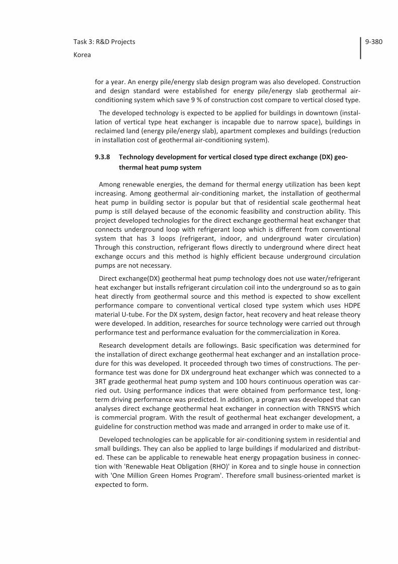
Task 3: R&D Projects
Korea
9-380
for a year. An energy pile/energy slab design program was also developed. Construction and design standard were established for energy pile/energy slab geothermal air-conditioning system which save 9 % of construction cost compare to vertical closed type.
The developed technology is expected to be applied for buildings in downtown (instal-lation of vertical type heat exchanger is incapable due to narrow space), buildings in reclaimed land (energy pile/energy slab), apartment complexes and buildings (reduction in installation cost of geothermal air-conditioning system).
9.3.8 Technology development for vertical closed type direct exchange (DX) geo-thermal heat pump system
Among renewable energies, the demand for thermal energy utilization has been kept increasing. Among geothermal air-conditioning market, the installation of geothermal heat pump in building sector is popular but that of residential scale geothermal heat pump is still delayed because of the economic feasibility and construction ability. This project developed technologies for the direct exchange geothermal heat exchanger that connects underground loop with refrigerant loop which is different from conventional system that has 3 loops (refrigerant, indoor, and underground water circulation) Through this construction, refrigerant flows directly to underground where direct heat exchange occurs and this method is highly efficient because underground circulation pumps are not necessary.
Direct exchange(DX) geothermal heat pump technology does not use water/refrigerant heat exchanger but installs refrigerant circulation coil into the underground so as to gain heat directly from geothermal source and this method is expected to show excellent performance compare to conventional vertical closed type system which uses HDPE material U-tube. For the DX system, design factor, heat recovery and heat release theory were developed. In addition, researches for source technology were carried out through performance test and performance evaluation for the commercialization in Korea.
Research development details are followings. Basic specification was determined for the installation of direct exchange geothermal heat exchanger and an installation proce-dure for this was developed. It proceeded through two times of constructions. The per-formance test was done for DX underground heat exchanger which was connected to a 3RT grade geothermal heat pump system and 100 hours continuous operation was car-ried out. Using performance indices that were obtained from performance test, long-term driving performance was predicted. In addition, a program was developed that can analyses direct exchange geothermal heat exchanger in connection with TRNSYS which is commercial program. With the result of geothermal heat exchanger development, a guideline for construction method was made and arranged in order to make use of it.
Developed technologies can be applicable for air-conditioning system in residential and small buildings. They can also be applied to large buildings if modularized and distribut-ed. These can be applicable to renewable heat energy propagation business in connec-tion with 'Renewable Heat Obligation (RHO)' in Korea and to single house in connection with 'One Million Green Homes Program'. Therefore small business-oriented market is expected to form.
Task 3: R&D Projects
Korea
9-381
Figure 9-6: Comparison of a conventional HDPE GSHP and a DX GSHP
(a) Conventional GSHP (b) DX GSHP
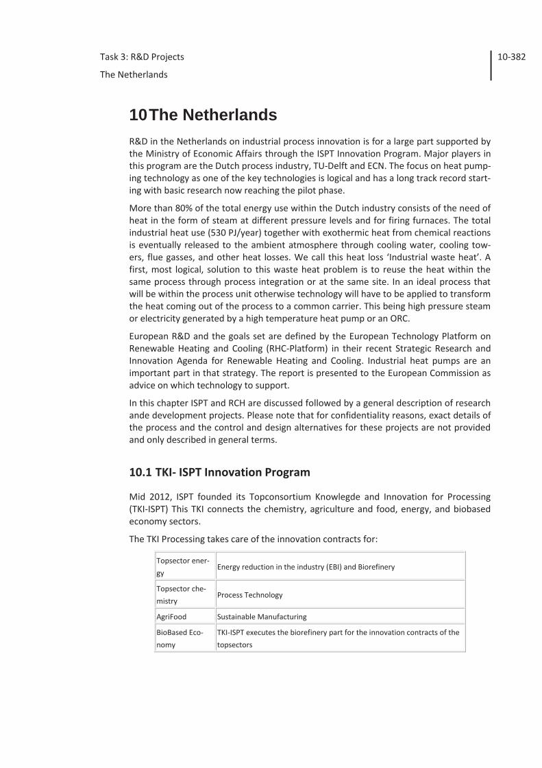
Task 3: R&D Projects
The Netherlands
10-382
10 The Netherlands R&D in the Netherlands on industrial process innovation is for a large part supported by the Ministry of Economic Affairs through the ISPT Innovation Program. Major players in this program are the Dutch process industry, TU-Delft and ECN. The focus on heat pump-ing technology as one of the key technologies is logical and has a long track record start-ing with basic research now reaching the pilot phase.
More than 80% of the total energy use within the Dutch industry consists of the need of heat in the form of steam at different pressure levels and for firing furnaces. The total industrial heat use (530 PJ/year) together with exothermic heat from chemical reactions is eventually released to the ambient atmosphere through cooling water, cooling tow-ers, flue gasses, and other heat losses. We call this heat loss ‘Industrial waste heat’. A first, most logical, solution to this waste heat problem is to reuse the heat within the same process through process integration or at the same site. In an ideal process that will be within the process unit otherwise technology will have to be applied to transform the heat coming out of the process to a common carrier. This being high pressure steam or electricity generated by a high temperature heat pump or an ORC.
European R&D and the goals set are defined by the European Technology Platform on Renewable Heating and Cooling (RHC-Platform) in their recent Strategic Research and Innovation Agenda for Renewable Heating and Cooling. Industrial heat pumps are an important part in that strategy. The report is presented to the European Commission as advice on which technology to support.
In this chapter ISPT and RCH are discussed followed by a general description of research ande development projects. Please note that for confidentiality reasons, exact details of the process and the control and design alternatives for these projects are not provided and only described in general terms.
10.1 TKI- ISPT Innovation Program
Mid 2012, ISPT founded its Topconsortium Knowlegde and Innovation for Processing (TKI-ISPT) This TKI connects the chemistry, agriculture and food, energy, and biobased economy sectors.
The TKI Processing takes care of the innovation contracts for:
Topsector ener-
gy
Energy reduction in the industry (EBI) and Biorefinery
Topsector che-
mistry
Process Technology
AgriFood Sustainable Manufacturing
BioBased Eco-
nomy
TKI-ISPT executes the biorefinery part for the innovation contracts of the
topsectors
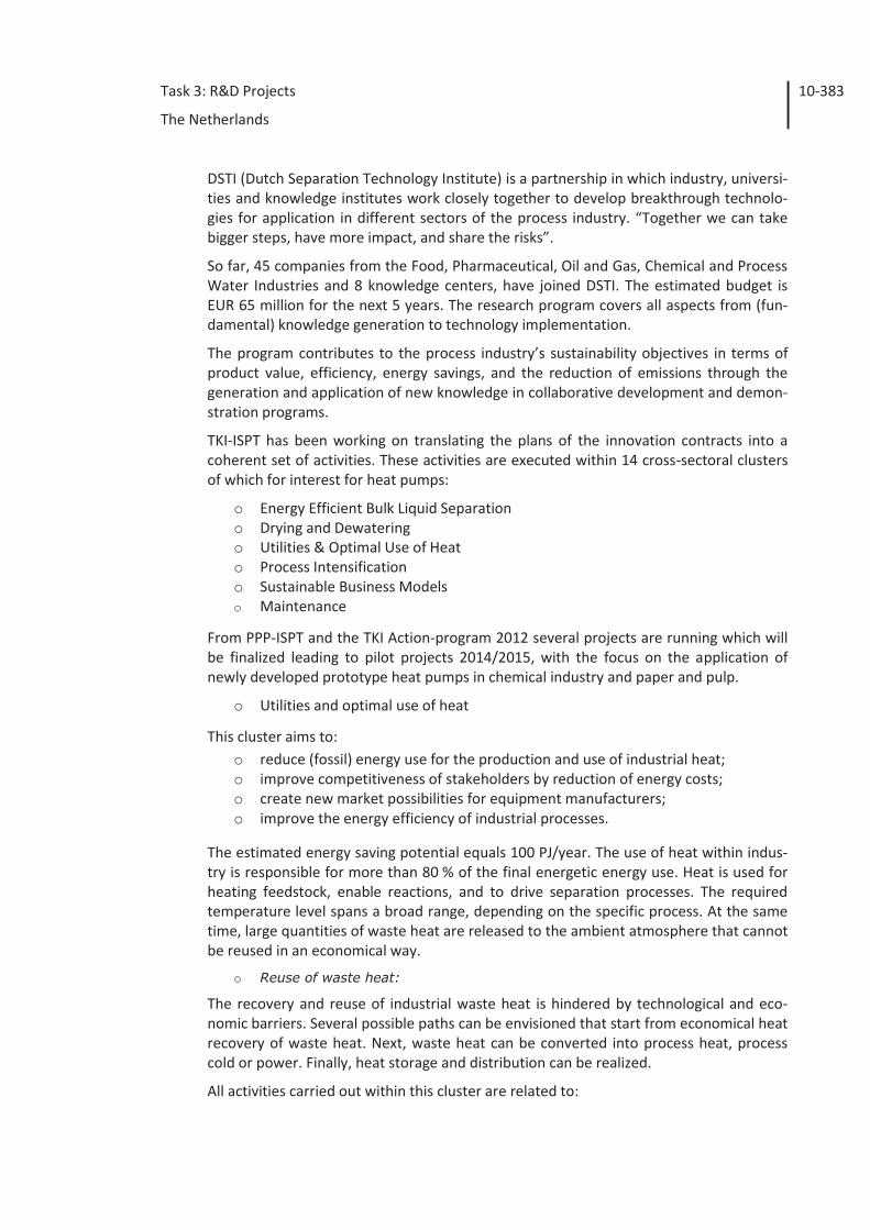
Task 3: R&D Projects
The Netherlands
10-383
DSTI (Dutch Separation Technology Institute) is a partnership in which industry, universi-ties and knowledge institutes work closely together to develop breakthrough technolo-gies for application in different sectors of the process industry. “Together we can take bigger steps, have more impact, and share the risks”.
So far, 45 companies from the Food, Pharmaceutical, Oil and Gas, Chemical and Process Water Industries and 8 knowledge centers, have joined DSTI. The estimated budget is EUR 65 million for the next 5 years. The research program covers all aspects from (fun-damental) knowledge generation to technology implementation.
The program contributes to the process industry’s sustainability objectives in terms of product value, efficiency, energy savings, and the reduction of emissions through the generation and application of new knowledge in collaborative development and demon-stration programs.
TKI-ISPT has been working on translating the plans of the innovation contracts into a coherent set of activities. These activities are executed within 14 cross-sectoral clusters of which for interest for heat pumps:
o Energy Efficient Bulk Liquid Separation o Drying and Dewatering o Utilities & Optimal Use of Heat o Process Intensification o Sustainable Business Models o Maintenance
From PPP-ISPT and the TKI Action-program 2012 several projects are running which will be finalized leading to pilot projects 2014/2015, with the focus on the application of newly developed prototype heat pumps in chemical industry and paper and pulp.
o Utilities and optimal use of heat
This cluster aims to: o reduce (fossil) energy use for the production and use of industrial heat; o improve competitiveness of stakeholders by reduction of energy costs; o create new market possibilities for equipment manufacturers; o improve the energy efficiency of industrial processes.
The estimated energy saving potential equals 100 PJ/year. The use of heat within indus-try is responsible for more than 80 % of the final energetic energy use. Heat is used for heating feedstock, enable reactions, and to drive separation processes. The required temperature level spans a broad range, depending on the specific process. At the same time, large quantities of waste heat are released to the ambient atmosphere that cannot be reused in an economical way.
o Reuse of waste heat:
The recovery and reuse of industrial waste heat is hindered by technological and eco-nomic barriers. Several possible paths can be envisioned that start from economical heat recovery of waste heat. Next, waste heat can be converted into process heat, process cold or power. Finally, heat storage and distribution can be realized.
All activities carried out within this cluster are related to:
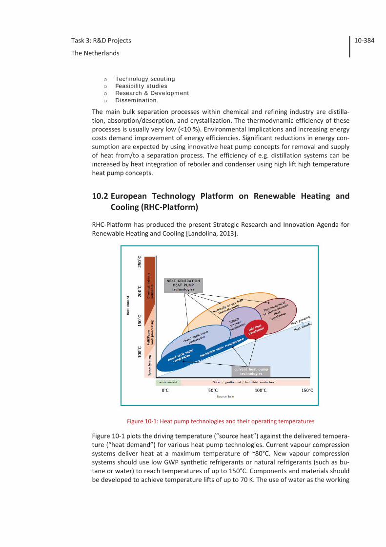
Task 3: R&D Projects
The Netherlands
10-384
o Technology scouting o Feasibility studies o Research & Development o Dissemination.
The main bulk separation processes within chemical and refining industry are distilla-tion, absorption/desorption, and crystallization. The thermodynamic efficiency of these processes is usually very low (<10 %). Environmental implications and increasing energy costs demand improvement of energy efficiencies. Significant reductions in energy con-sumption are expected by using innovative heat pump concepts for removal and supply of heat from/to a separation process. The efficiency of e.g. distillation systems can be increased by heat integration of reboiler and condenser using high lift high temperature heat pump concepts.
10.2 European Technology Platform on Renewable Heating and Cooling (RHC-Platform)
RHC-Platform has produced the present Strategic Research and Innovation Agenda for Renewable Heating and Cooling [Landolina, 2013].
Figure 10-1: Heat pump technologies and their operating temperatures
Figure 10-1 plots the driving temperature (“source heat”) against the delivered tempera-ture (“heat demand”) for various heat pump technologies. Current vapour compression systems deliver heat at a maximum temperature of ~80°C. New vapour compression systems should use low GWP synthetic refrigerants or natural refrigerants (such as bu-tane or water) to reach temperatures of up to 150°C. Components and materials should be developed to achieve temperature lifts of up to 70 K. The use of water as the working
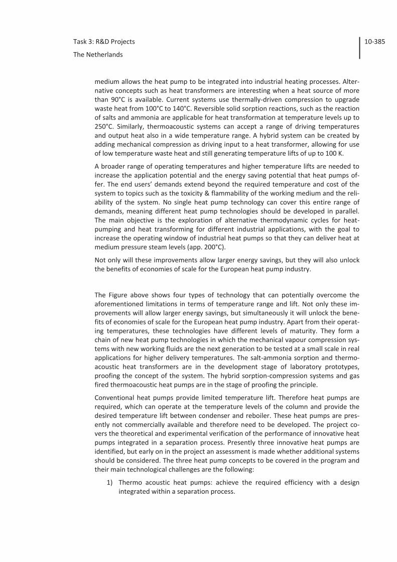
Task 3: R&D Projects
The Netherlands
10-385
medium allows the heat pump to be integrated into industrial heating processes. Alter-native concepts such as heat transformers are interesting when a heat source of more than 90°C is available. Current systems use thermally-driven compression to upgrade waste heat from 100°C to 140°C. Reversible solid sorption reactions, such as the reaction of salts and ammonia are applicable for heat transformation at temperature levels up to 250°C. Similarly, thermoacoustic systems can accept a range of driving temperatures and output heat also in a wide temperature range. A hybrid system can be created by adding mechanical compression as driving input to a heat transformer, allowing for use of low temperature waste heat and still generating temperature lifts of up to 100 K.
A broader range of operating temperatures and higher temperature lifts are needed to increase the application potential and the energy saving potential that heat pumps of-fer. The end users’ demands extend beyond the required temperature and cost of the system to topics such as the toxicity & flammability of the working medium and the reli-ability of the system. No single heat pump technology can cover this entire range of demands, meaning different heat pump technologies should be developed in parallel. The main objective is the exploration of alternative thermodynamic cycles for heat-pumping and heat transforming for different industrial applications, with the goal to increase the operating window of industrial heat pumps so that they can deliver heat at medium pressure steam levels (app. 200°C).
Not only will these improvements allow larger energy savings, but they will also unlock the benefits of economies of scale for the European heat pump industry.
The Figure above shows four types of technology that can potentially overcome the aforementioned limitations in terms of temperature range and lift. Not only these im-provements will allow larger energy savings, but simultaneously it will unlock the bene-fits of economies of scale for the European heat pump industry. Apart from their operat-ing temperatures, these technologies have different levels of maturity. They form a chain of new heat pump technologies in which the mechanical vapour compression sys-tems with new working fluids are the next generation to be tested at a small scale in real applications for higher delivery temperatures. The salt-ammonia sorption and thermo-acoustic heat transformers are in the development stage of laboratory prototypes, proofing the concept of the system. The hybrid sorption-compression systems and gas fired thermoacoustic heat pumps are in the stage of proofing the principle.
Conventional heat pumps provide limited temperature lift. Therefore heat pumps are required, which can operate at the temperature levels of the column and provide the desired temperature lift between condenser and reboiler. These heat pumps are pres-ently not commercially available and therefore need to be developed. The project co-vers the theoretical and experimental verification of the performance of innovative heat pumps integrated in a separation process. Presently three innovative heat pumps are identified, but early on in the project an assessment is made whether additional systems should be considered. The three heat pump concepts to be covered in the program and their main technological challenges are the following:
1) Thermo acoustic heat pumps: achieve the required efficiency with a design integrated within a separation process.
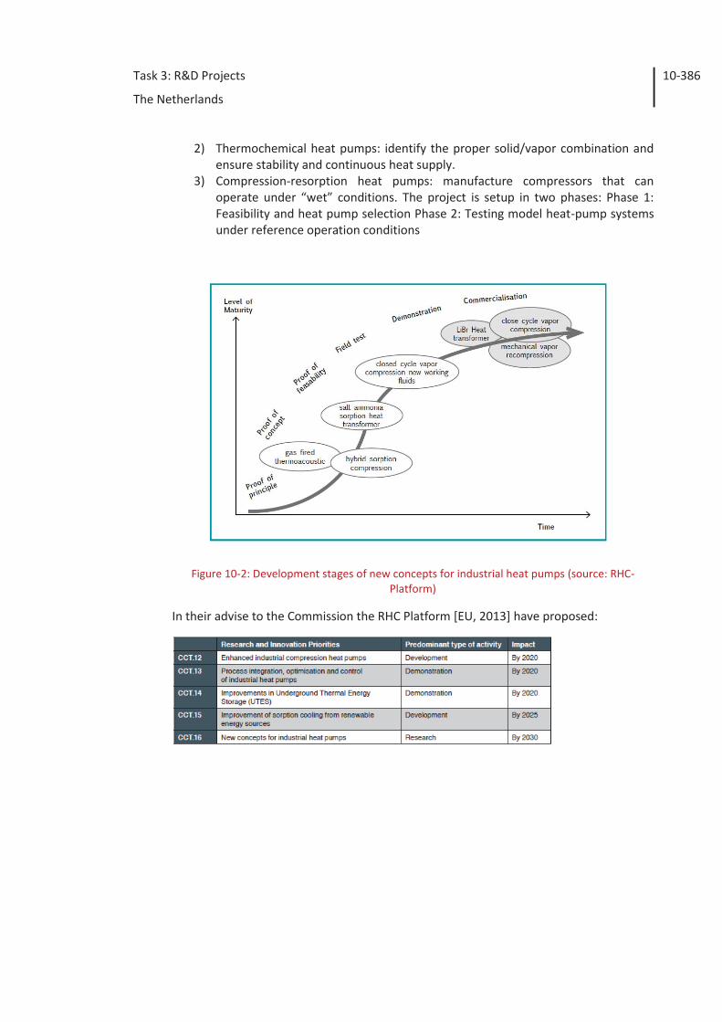
Task 3: R&D Projects
The Netherlands
10-386
2) Thermochemical heat pumps: identify the proper solid/vapor combination and ensure stability and continuous heat supply.
3) Compression-resorption heat pumps: manufacture compressors that can operate under “wet” conditions. The project is setup in two phases: Phase 1: Feasibility and heat pump selection Phase 2: Testing model heat-pump systems under reference operation conditions
Figure 10-2: Development stages of new concepts for industrial heat pumps (source: RHC-Platform)
In their advise to the Commission the RHC Platform [EU, 2013] have proposed:

Task 3: R&D Projects
The Netherlands
10-387
Task 3: R&D Projects
The Netherlands
10-388
10.3 Technological developments
Before 2005, heat pumps were merely refrigeration plants where pressures are in-creased to deliver condensing heat at temperatures of 35°C up to 50°C. This operation range also depends on the evaporation temperature, efficiency and pressure ratio. The refrigeration compressors have a design pressure of 25 bar. This is also a limit for higher condensing temperatures. The large manufacturers of industrial refrigeration in the Netherlands, i.e. GEA-Grenco with their seat in Den Bosch and IBK from Houten, have discovered this new market of high temperature applications and already executed pro-jects (see factsheets in chapter 4). A large application potential of industrial heat pumps is still not used because of these limited supply temperatures of about 100°C of com-mercially available heat pumps. If these supply temperatures could be increased, more industrial processes could be improved in their energy efficiency. The main reason for the limited temperatures has been the absence of adequate working fluids [Reissner, 2013].
10.3.1 CO2 – Heat Pump
Beginning of 2000 the refrigeration industry is introducing CO2 again as refrigerant and secondary refrigerant. CO2 is a natural refrigerant without ozone depletion potential and with a low global warming potential. It is therefore a sustainable alternative for the syn-thetic refrigerants such as the HFC types.
Since CO2 is a high pressure refrigerant, the refrigeration industry had to develop equipment with design pressures up to 45 bar. It is this development that has led to the construction of 50 bar industrial compressors. Using these compressors with ammonia or HFC like R134a as refrigerant, high temperature heat pumps (HT heat pumps) can be produced for industrial purposes. Condensation heat at temperatures up to 80°C can be delivered in a large variation of capacities with good efficiency.
HT heat pumps are also executed with CO2 as refrigerant in a transcritical cycle. Larger units for water heating from 10° up to 70°C are available in a range up to 120 kW run-ning with any heat source and can even produce cooled water (8°C). Essential is that the CO2 at condensing pressure can be strongly cooled in order to maintain a sufficient effi-ciency. This is possible by a process flow that starts to heat up at e.g. 15°C. The COP of CO2 can be higher than ammonia in case of high temperatures differences. Compressor sizes for these high pressures are however limited available.
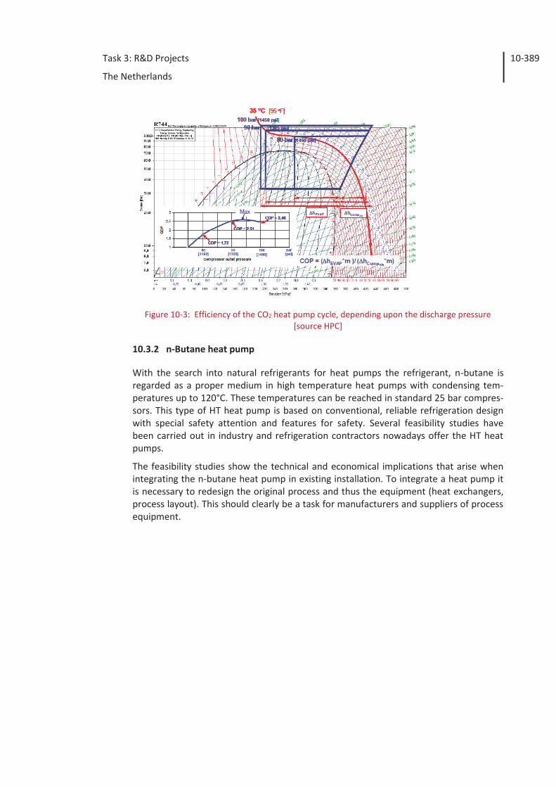
Task 3: R&D Projects
The Netherlands
10-389
Figure 10-3: Efficiency of the CO2 heat pump cycle, depending upon the discharge pressure [source HPC]
10.3.2 n-Butane heat pump
With the search into natural refrigerants for heat pumps the refrigerant, n-butane is regarded as a proper medium in high temperature heat pumps with condensing tem-peratures up to 120°C. These temperatures can be reached in standard 25 bar compres-sors. This type of HT heat pump is based on conventional, reliable refrigeration design with special safety attention and features for safety. Several feasibility studies have been carried out in industry and refrigeration contractors nowadays offer the HT heat pumps.
The feasibility studies show the technical and economical implications that arise when integrating the n-butane heat pump in existing installation. To integrate a heat pump it is necessary to redesign the original process and thus the equipment (heat exchangers, process layout). This should clearly be a task for manufacturers and suppliers of process equipment.
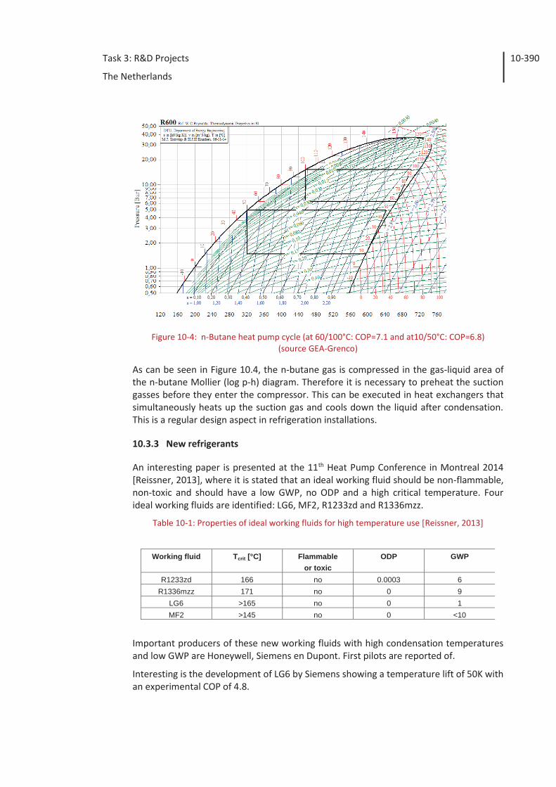
Task 3: R&D Projects
The Netherlands
10-390
Figure 10-4: n-Butane heat pump cycle (at 60/100°C: COP=7.1 and at10/50°C: COP=6.8) (source GEA-Grenco)
As can be seen in Figure 10.4, the n-butane gas is compressed in the gas-liquid area of the n-butane Mollier (log p-h) diagram. Therefore it is necessary to preheat the suction gasses before they enter the compressor. This can be executed in heat exchangers that simultaneously heats up the suction gas and cools down the liquid after condensation. This is a regular design aspect in refrigeration installations.
10.3.3 New refrigerants
An interesting paper is presented at the 11th Heat Pump Conference in Montreal 2014 [Reissner, 2013], where it is stated that an ideal working fluid should be non-flammable, non-toxic and should have a low GWP, no ODP and a high critical temperature. Four ideal working fluids are identified: LG6, MF2, R1233zd and R1336mzz.
Table 10-1: Properties of ideal working fluids for high temperature use [Reissner, 2013]
Important producers of these new working fluids with high condensation temperatures and low GWP are Honeywell, Siemens en Dupont. First pilots are reported of.
Interesting is the development of LG6 by Siemens showing a temperature lift of 50K with an experimental COP of 4.8.
Working fluid Tcrit [°C] Flammable
or toxic ODP GWP
R1233zd 166 no 0.0003 6 R1336mzz 171 no 0 9
LG6 >165 no 0 1 MF2 >145 no 0 <10
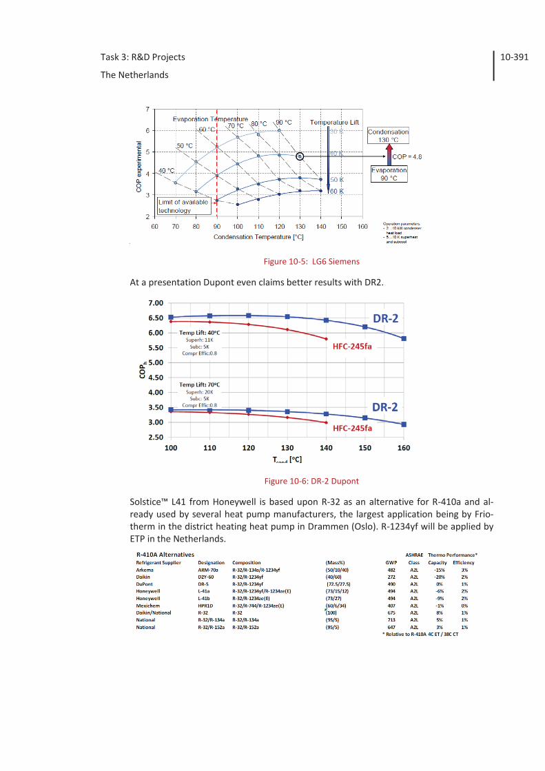
Task 3: R&D Projects
The Netherlands
10-391
Figure 10-5: LG6 Siemens
At a presentation Dupont even claims better results with DR2.
Figure 10-6: DR-2 Dupont
Solstice™ L41 from Honeywell is based upon R-32 as an alternative for R-410a and al-ready used by several heat pump manufacturers, the largest application being by Frio-therm in the district heating heat pump in Drammen (Oslo). R-1234yf will be applied by ETP in the Netherlands.
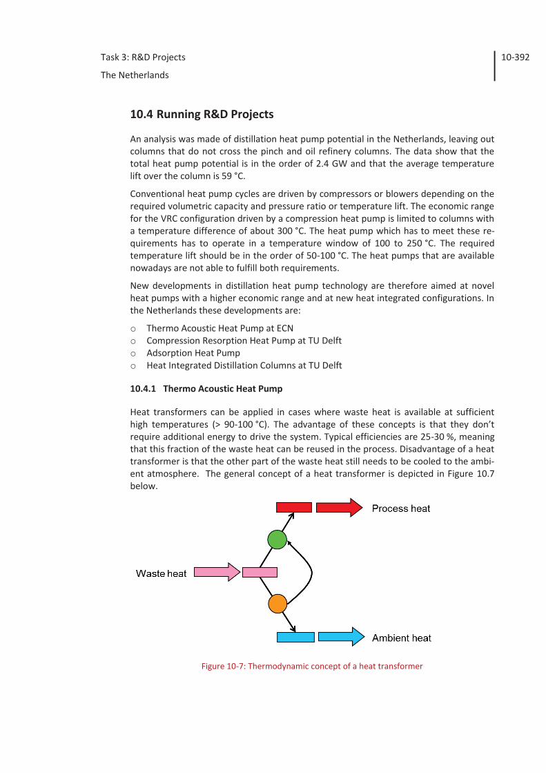
Task 3: R&D Projects
The Netherlands
10-392
10.4 Running R&D Projects
An analysis was made of distillation heat pump potential in the Netherlands, leaving out columns that do not cross the pinch and oil refinery columns. The data show that the total heat pump potential is in the order of 2.4 GW and that the average temperature lift over the column is 59 °C.
Conventional heat pump cycles are driven by compressors or blowers depending on the required volumetric capacity and pressure ratio or temperature lift. The economic range for the VRC configuration driven by a compression heat pump is limited to columns with a temperature difference of about 300 °C. The heat pump which has to meet these re-quirements has to operate in a temperature window of 100 to 250 °C. The required temperature lift should be in the order of 50-100 °C. The heat pumps that are available nowadays are not able to fulfill both requirements.
New developments in distillation heat pump technology are therefore aimed at novel heat pumps with a higher economic range and at new heat integrated configurations. In the Netherlands these developments are:
o Thermo Acoustic Heat Pump at ECN o Compression Resorption Heat Pump at TU Delft o Adsorption Heat Pump o Heat Integrated Distillation Columns at TU Delft
10.4.1 Thermo Acoustic Heat Pump
Heat transformers can be applied in cases where waste heat is available at sufficient high temperatures (> 90-100 °C). The advantage of these concepts is that they don’t require additional energy to drive the system. Typical efficiencies are 25-30 %, meaning that this fraction of the waste heat can be reused in the process. Disadvantage of a heat transformer is that the other part of the waste heat still needs to be cooled to the ambi-ent atmosphere. The general concept of a heat transformer is depicted in Figure 10.7 below.
Figure 10-7: Thermodynamic concept of a heat transformer
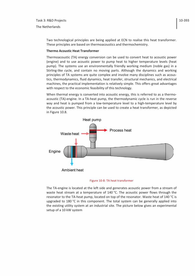
Task 3: R&D Projects
The Netherlands
10-393
Two technological principles are being applied at ECN to realise this heat transformer. These principles are based on thermoacoustics and thermochemistry.
Thermo Acoustic Heat Transformer
Thermoacoustic (TA) energy conversion can be used to convert heat to acoustic power (engine) and to use acoustic power to pump heat to higher temperature levels (heat pump). The systems use an environmentally friendly working medium (noble gas) in a Stirling-like cycle, and contain no moving parts. Although the dynamics and working principles of TA systems are quite complex and involve many disciplines such as acous-tics, thermodynamics, fluid dynamics, heat transfer, structural mechanics, and electrical machines, the practical implementation is relatively simple. This offers great advantages with respect to the economic feasibility of this technology.
When thermal energy is converted into acoustic energy, this is referred to as a thermo-acoustic (TA)-engine. In a TA-heat pump, the thermodynamic cycle is run in the reverse way and heat is pumped from a low-temperature level to a high-temperature level by the acoustic power. This principle can be used to create a heat transformer, as depicted in Figure 10.8.
Figure 10-8: TA heat transformer
The TA-engine is located at the left side and generates acoustic power from a stream of waste heat stream at a temperature of 140 °C. The acoustic power flows through the resonator to the TA-heat pump, located on top of the resonator. Waste heat of 140 °C is upgraded to 180 °C in this component. The total system can be generally applied into the existing utility system at an industrial site. The picture below gives an experimental setup of a 10 kW system
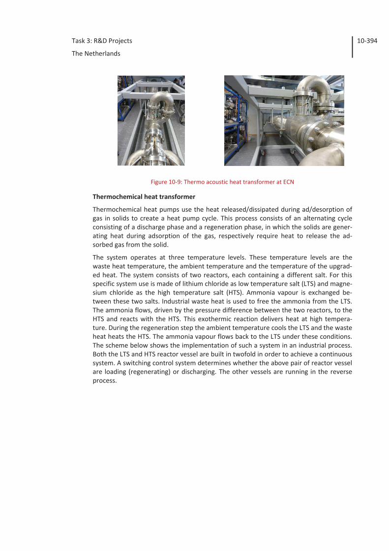
Task 3: R&D Projects
The Netherlands
10-394
Figure 10-9: Thermo acoustic heat transformer at ECN
Thermochemical heat transformer
Thermochemical heat pumps use the heat released/dissipated during ad/desorption of gas in solids to create a heat pump cycle. This process consists of an alternating cycle consisting of a discharge phase and a regeneration phase, in which the solids are gener-ating heat during adsorption of the gas, respectively require heat to release the ad-sorbed gas from the solid.
The system operates at three temperature levels. These temperature levels are the waste heat temperature, the ambient temperature and the temperature of the upgrad-ed heat. The system consists of two reactors, each containing a different salt. For this specific system use is made of lithium chloride as low temperature salt (LTS) and magne-sium chloride as the high temperature salt (HTS). Ammonia vapour is exchanged be-tween these two salts. Industrial waste heat is used to free the ammonia from the LTS. The ammonia flows, driven by the pressure difference between the two reactors, to the HTS and reacts with the HTS. This exothermic reaction delivers heat at high tempera-ture. During the regeneration step the ambient temperature cools the LTS and the waste heat heats the HTS. The ammonia vapour flows back to the LTS under these conditions. The scheme below shows the implementation of such a system in an industrial process. Both the LTS and HTS reactor vessel are built in twofold in order to achieve a continuous system. A switching control system determines whether the above pair of reactor vessel are loading (regenerating) or discharging. The other vessels are running in the reverse process.
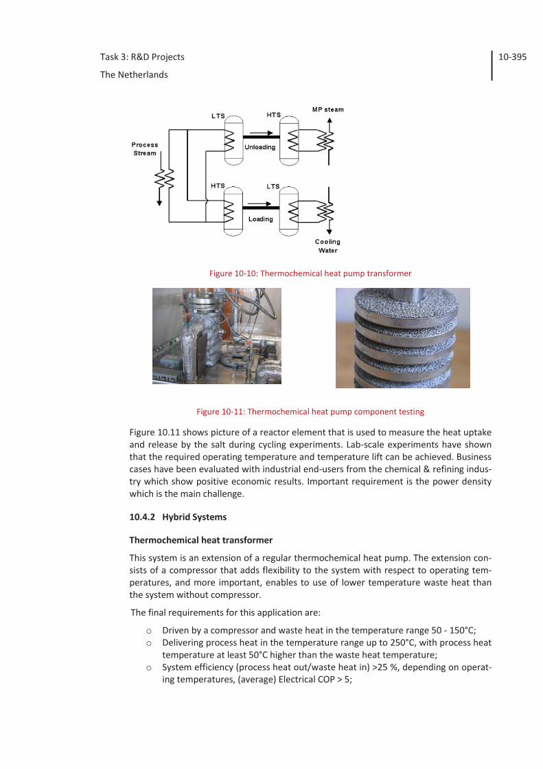
Task 3: R&D Projects
The Netherlands
10-395
Figure 10-10: Thermochemical heat pump transformer
Figure 10-11: Thermochemical heat pump component testing
Figure 10.11 shows picture of a reactor element that is used to measure the heat uptake and release by the salt during cycling experiments. Lab-scale experiments have shown that the required operating temperature and temperature lift can be achieved. Business cases have been evaluated with industrial end-users from the chemical & refining indus-try which show positive economic results. Important requirement is the power density which is the main challenge.
10.4.2 Hybrid Systems
Thermochemical heat transformer
This system is an extension of a regular thermochemical heat pump. The extension con-sists of a compressor that adds flexibility to the system with respect to operating tem-peratures, and more important, enables to use of lower temperature waste heat than the system without compressor.
The final requirements for this application are:
o Driven by a compressor and waste heat in the temperature range 50 - 150°C; o Delivering process heat in the temperature range up to 250°C, with process heat
temperature at least 50°C higher than the waste heat temperature; o System efficiency (process heat out/waste heat in) >25 %, depending on operat-
ing temperatures, (average) Electrical COP > 5;
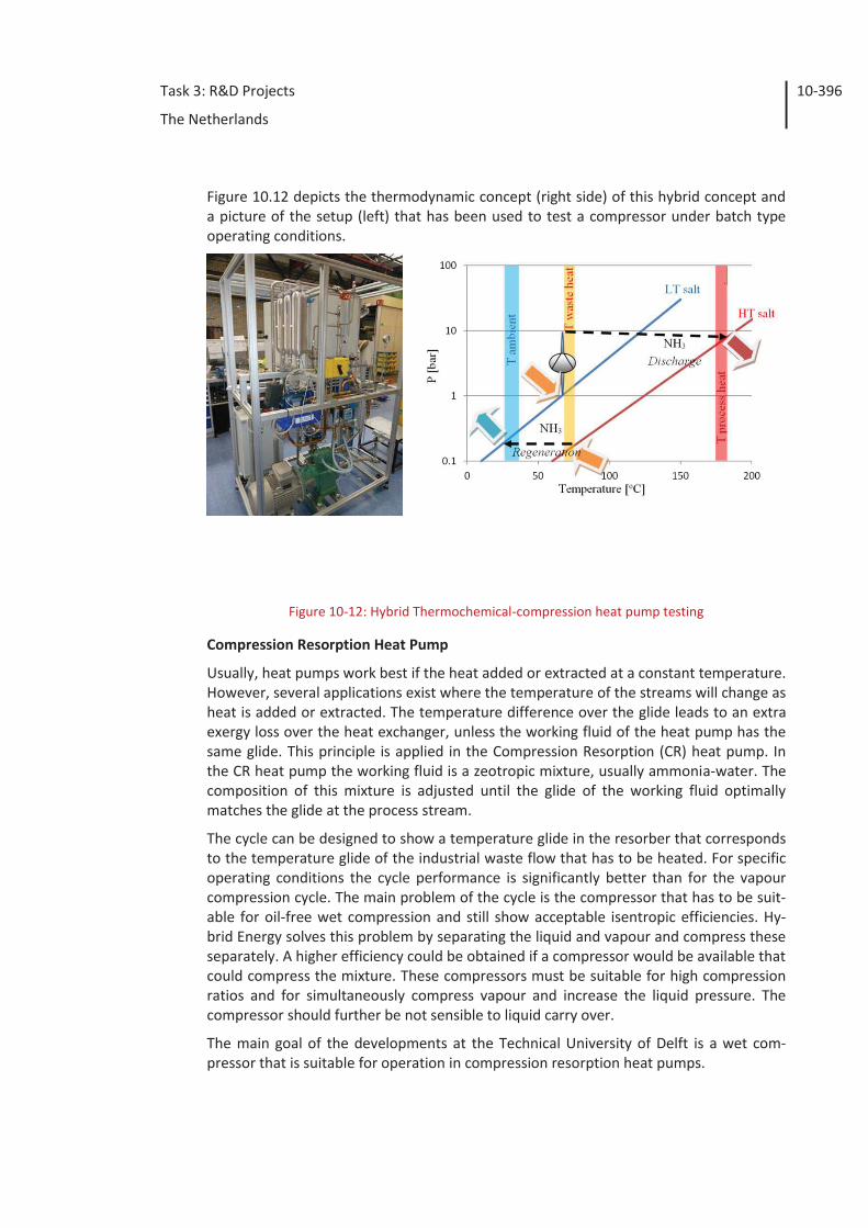
Task 3: R&D Projects
The Netherlands
10-396
Figure 10.12 depicts the thermodynamic concept (right side) of this hybrid concept and a picture of the setup (left) that has been used to test a compressor under batch type operating conditions.
Figure 10-12: Hybrid Thermochemical-compression heat pump testing
Compression Resorption Heat Pump
Usually, heat pumps work best if the heat added or extracted at a constant temperature. However, several applications exist where the temperature of the streams will change as heat is added or extracted. The temperature difference over the glide leads to an extra exergy loss over the heat exchanger, unless the working fluid of the heat pump has the same glide. This principle is applied in the Compression Resorption (CR) heat pump. In the CR heat pump the working fluid is a zeotropic mixture, usually ammonia-water. The composition of this mixture is adjusted until the glide of the working fluid optimally matches the glide at the process stream.
The cycle can be designed to show a temperature glide in the resorber that corresponds to the temperature glide of the industrial waste flow that has to be heated. For specific operating conditions the cycle performance is significantly better than for the vapour compression cycle. The main problem of the cycle is the compressor that has to be suit-able for oil-free wet compression and still show acceptable isentropic efficiencies. Hy-brid Energy solves this problem by separating the liquid and vapour and compress these separately. A higher efficiency could be obtained if a compressor would be available that could compress the mixture. These compressors must be suitable for high compression ratios and for simultaneously compress vapour and increase the liquid pressure. The compressor should further be not sensible to liquid carry over.
The main goal of the developments at the Technical University of Delft is a wet com-pressor that is suitable for operation in compression resorption heat pumps.
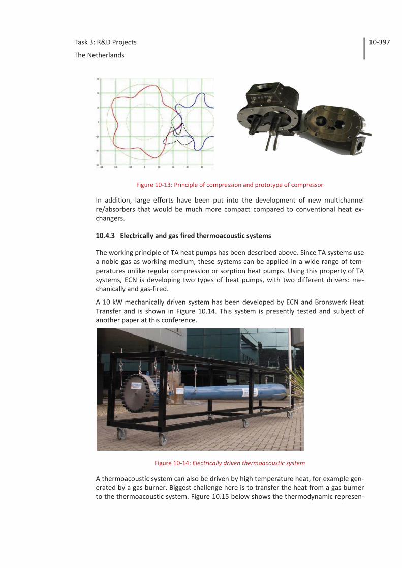
Task 3: R&D Projects
The Netherlands
10-397
Figure 10-13: Principle of compression and prototype of compressor
In addition, large efforts have been put into the development of new multichannel re/absorbers that would be much more compact compared to conventional heat ex-changers.
10.4.3 Electrically and gas fired thermoacoustic systems
The working principle of TA heat pumps has been described above. Since TA systems use a noble gas as working medium, these systems can be applied in a wide range of tem-peratures unlike regular compression or sorption heat pumps. Using this property of TA systems, ECN is developing two types of heat pumps, with two different drivers: me-chanically and gas-fired.
A 10 kW mechanically driven system has been developed by ECN and Bronswerk Heat Transfer and is shown in Figure 10.14. This system is presently tested and subject of another paper at this conference.
Figure 10-14: Electrically driven thermoacoustic system
A thermoacoustic system can also be driven by high temperature heat, for example gen-erated by a gas burner. Biggest challenge here is to transfer the heat from a gas burner to the thermoacoustic system. Figure 10.15 below shows the thermodynamic represen-
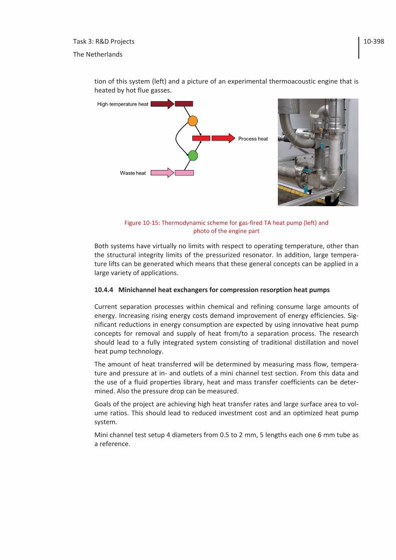
Task 3: R&D Projects
The Netherlands
10-398
tion of this system (left) and a picture of an experimental thermoacoustic engine that is heated by hot flue gasses.
Figure 10-15: Thermodynamic scheme for gas-fired TA heat pump (left) and photo of the engine part
Both systems have virtually no limits with respect to operating temperature, other than the structural integrity limits of the pressurized resonator. In addition, large tempera-ture lifts can be generated which means that these general concepts can be applied in a large variety of applications.
10.4.4 Minichannel heat exchangers for compression resorption heat pumps
Current separation processes within chemical and refining consume large amounts of energy. Increasing rising energy costs demand improvement of energy efficiencies. Sig-nificant reductions in energy consumption are expected by using innovative heat pump concepts for removal and supply of heat from/to a separation process. The research should lead to a fully integrated system consisting of traditional distillation and novel heat pump technology.
The amount of heat transferred will be determined by measuring mass flow, tempera-ture and pressure at in- and outlets of a mini channel test section. From this data and the use of a fluid properties library, heat and mass transfer coefficients can be deter-mined. Also the pressure drop can be measured.
Goals of the project are achieving high heat transfer rates and large surface area to vol-ume ratios. This should lead to reduced investment cost and an optimized heat pump system.
Mini channel test setup 4 diameters from 0.5 to 2 mm, 5 lengths each one 6 mm tube as a reference.
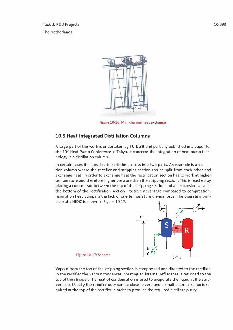
Task 3: R&D Projects
The Netherlands
10-399
Figure 10-16: Mini channel heat exchanger
10.5 Heat Integrated Distillation Columns
A large part of the work is undertaken by TU-Delft and partially published in a paper for the 10th Heat Pump Conference in Tokyo. It concerns the integration of heat pump tech-nology in a distillation column.
In certain cases it is possible to split the process into two parts. An example is a distilla-tion column where the rectifier and stripping section can be split from each other and exchange heat. In order to exchange heat the rectification section has to work at higher temperature and therefore higher pressure than the stripping section. This is reached by placing a compressor between the top of the stripping section and an expansion valve at the bottom of the rectification section. Possible advantage compared to compression-resorption heat pumps is the lack of one temperature driving force. The operating prin-ciple of a HIDiC is shown in Figure 10.17.
Figure 10-17: Scheme
Vapour from the top of the stripping section is compressed and directed to the rectifier. In the rectifier the vapour condenses, creating an internal reflux that is returned to the top of the stripper. The heat of condensation is used to evaporate the liquid at the strip-per side. Usually the reboiler duty can be close to zero and a small external reflux is re-quired at the top of the rectifier in order to produce the required distillate purity.
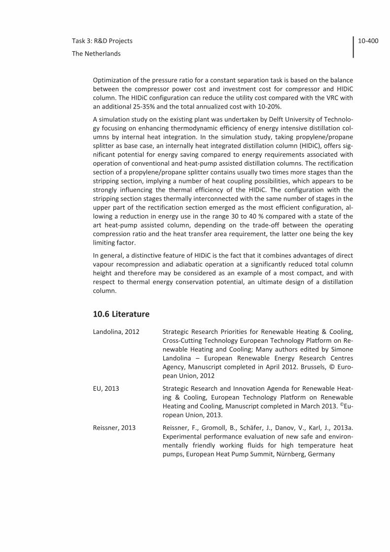
Task 3: R&D Projects
The Netherlands
10-400
Optimization of the pressure ratio for a constant separation task is based on the balance between the compressor power cost and investment cost for compressor and HIDiC column. The HIDiC configuration can reduce the utility cost compared with the VRC with an additional 25-35% and the total annualized cost with 10-20%.
A simulation study on the existing plant was undertaken by Delft University of Technolo-gy focusing on enhancing thermodynamic efficiency of energy intensive distillation col-umns by internal heat integration. In the simulation study, taking propylene/propane splitter as base case, an internally heat integrated distillation column (HIDiC), offers sig-nificant potential for energy saving compared to energy requirements associated with operation of conventional and heat-pump assisted distillation columns. The rectification section of a propylene/propane splitter contains usually two times more stages than the stripping section, implying a number of heat coupling possibilities, which appears to be strongly influencing the thermal efficiency of the HIDiC. The configuration with the stripping section stages thermally interconnected with the same number of stages in the upper part of the rectification section emerged as the most efficient configuration, al-lowing a reduction in energy use in the range 30 to 40 % compared with a state of the art heat-pump assisted column, depending on the trade-off between the operating compression ratio and the heat transfer area requirement, the latter one being the key limiting factor.
In general, a distinctive feature of HIDiC is the fact that it combines advantages of direct vapour recompression and adiabatic operation at a significantly reduced total column height and therefore may be considered as an example of a most compact, and with respect to thermal energy conservation potential, an ultimate design of a distillation column.
10.6 Literature
Landolina, 2012 Strategic Research Priorities for Renewable Heating & Cooling, Cross-Cutting Technology European Technology Platform on Re-newable Heating and Cooling; Many authors edited by Simone Landolina – European Renewable Energy Research Centres Agency, Manuscript completed in April 2012. Brussels, © Euro-pean Union, 2012
EU, 2013 Strategic Research and Innovation Agenda for Renewable Heat-ing & Cooling, European Technology Platform on Renewable Heating and Cooling, Manuscript completed in March 2013. ©Eu-ropean Union, 2013.
Reissner, 2013 Reissner, F., Gromoll, B., Schäfer, J., Danov, V., Karl, J., 2013a. Experimental performance evaluation of new safe and environ-mentally friendly working fluids for high temperature heat pumps, European Heat Pump Summit, Nürnberg, Germany


![회사소개서(2012년수정).ppt [호환 모드] Energy Solar, Geothermal Heat Pumps Specialized in the development dissemination SHINYANG ENERGY 신양에너지회사소개서](https://static.fdocument.pub/doc/165x107/5ab0415d7f8b9a59478e6497/2012ppt-energy-solar-geothermal-heat.jpg)
