ALUMINUM PIPE SPECIFICATION 3/4” thru 3” · PDF fileALUMINUM PIPE SPECIFICATION...
16
Transcript of ALUMINUM PIPE SPECIFICATION 3/4” thru 3” · PDF fileALUMINUM PIPE SPECIFICATION...
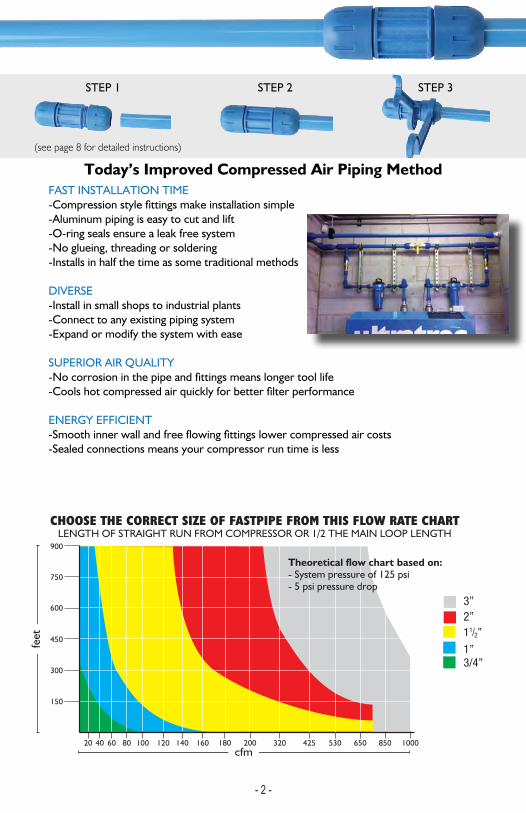
ALUMINUM PIPE SPECIFICATION 3/4” thru 3” -alloy grade 6063-T5 or 5042-seamless extruded to ASTM B241-blue powder coat, color RAL5012 outside-non chromate conversion coating inside
TECHNICAL SPECIFICATIONS -190 psi working pressure-0 Deg F to 140 Deg F-compatible with all types of compressor lubricants-compressed air, vacuum, inert gas
FITTINGS SPECIFICATION 3/4” thru 2”
-bite ring: stainless steel-nylon 6 base with fiberglass reinforcement
-o-ring: Nitrile
FITTINGS SPECIFICATION 3”
-bite ring: stainless steel-DieCast Aluminum Alloy
-o-ring: Nitrile-Electrocoated
FITTINGS PARTS BREAKDOWNA) O-RINGB) BACKERC) SS BITE RINGD) COLLETE) CONE NUTF) TENSION O-RING*
SPARE PARTS KIT (INCLUDES A AND C)
SIZE PART NUMBER
1” F2076
3/4” F1076
2” F50763” FI7076
1 1/2” F4076
GENERAL SYSTEM RATINGS -conforms to ASME B31.1-fire resistant to flammability standard UL94HB-OSHA Compliant
A B C EDF
*Tension O-ring (F) is a design enhancement on the 3/4” and 1” sizes. This will be phased in over the next year. There are no performance issues with fittings without this O-ring.
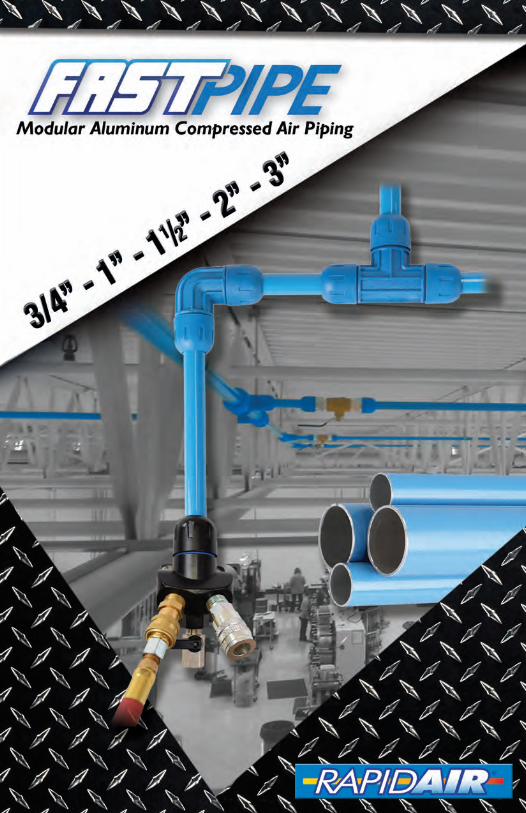
900
750
600
450
300
150
20 40 60 80 100 120 140 160 180 200 320 425 530 650 850 1000
feet
cfm
2”3”
11/2”
1”3/4”
CHOOSE THE CORRECT SIZE OF FASTPIPE FROM THIS FLOW RATE CHARTLENGTH OF STRAIGHT RUN FROM COMPRESSOR OR 1/2 THE MAIN LOOP LENGTH
Theoretical flow chart based on:- System pressure of 125 psi- 5 psi pressure drop
1
FAST INSTALLATION TIME
-Aluminum piping is easy to cut and lift-O-ring seals ensure a leak free system -No glueing, threading or soldering-Installs in half the time as some traditional methods
DIVERSE-Install in small shops to industrial plants-Connect to any existing piping system-Expand or modify the system with ease
SUPERIOR AIR QUALITY
ENERGY EFFICIENT
-Sealed connections means your compressor run time is less
Today’s Improved Compressed Air Piping Method
Traditional Compressed Air Piping MethodsBLACK PIPE- requires special threading equipment/skill in fabrication for joining- prone to rust and loose scale deposits over time
- inexpensive material costs- longer time needed for installation
COPPER- skill in soldering needed to assemble joints
- not all types are suitable for pressure- expensive material costs due to the high price of copper raw material- high installation cost
PVC- not recommended for compressed air by the manufacturer- becomes brittle over time and is not safe, can explode, sending shrapnel everywhere- banned by OSHA for above ground applications
STEP 1 STEP 2 STEP 3
(see page 8 for detailed instructions)
- 2 - - 3 -
ALUMINUM PIPE SPECIFICATION 3/4” thru 3” -alloy grade 6063-T5 or 5042-seamless extruded to ASTM B241-blue powder coat, color RAL5012 outside-non chromate conversion coating inside
TECHNICAL SPECIFICATIONS -190 psi working pressure-0 Deg F to 140 Deg F-compatible with all types of compressor lubricants-compressed air, vacuum, inert gas
FITTINGS SPECIFICATION 3/4” thru 2”
-bite ring: stainless steel-nylon 6 base with fiberglass reinforcement
-o-ring: Nitrile
FITTINGS SPECIFICATION 3”
-bite ring: stainless steel-DieCast Aluminum Alloy
-o-ring: Nitrile-Electrocoated
FITTINGS PARTS BREAKDOWNA) O-RINGB) BACKERC) SS BITE RINGD) COLLETE) CONE NUTF) TENSION O-RING*
SPARE PARTS KIT (INCLUDES A AND C)
SIZE PART NUMBER
1” F2076
3/4” F1076
2” F50763” FI7076
1 1/2” F4076
GENERAL SYSTEM RATINGS -conforms to ASME B31.1-fire resistant to flammability standard UL94HB-OSHA Compliant
A B C EDF
*Tension O-ring (F) is a design enhancement on the 3/4” and 1” sizes. This will be phased in over the next year. There are no performance issues with fittings without this O-ring.
1
FAST INSTALLATION TIME
-Aluminum piping is easy to cut and lift-O-ring seals ensure a leak free system -No glueing, threading or soldering-Installs in half the time as some traditional methods
DIVERSE-Install in small shops to industrial plants-Connect to any existing piping system-Expand or modify the system with ease
SUPERIOR AIR QUALITY
ENERGY EFFICIENT
-Sealed connections means your compressor run time is less
Today’s Improved Compressed Air Piping Method
Traditional Compressed Air Piping MethodsBLACK PIPE- requires special threading equipment/skill in fabrication for joining- prone to rust and loose scale deposits over time
- inexpensive material costs- longer time needed for installation
COPPER- skill in soldering needed to assemble joints
- not all types are suitable for pressure- expensive material costs due to the high price of copper raw material- high installation cost
PVC- not recommended for compressed air by the manufacturer- becomes brittle over time and is not safe, can explode, sending shrapnel everywhere- banned by OSHA for above ground applications
STEP 1 STEP 2 STEP 3
(see page 8 for detailed instructions)
- 2 - - 3 -

- 4 - - 5 -
SIZE MM PART # OUTSIDE INSIDE LENGTH WEIGHT
3/4” 20mm F1000 .79 in .69 in 19ft 8in 2.6 lbs
1” 25mm F2000 .98 in .87 in 19ft 8in 4.2 lbs
11/2” 40mm F4000 1.57 in 1.43 in 19ft 8in 8.8 lbs
2” 50mm F5000 1.97 in 1.81 in 19ft 8in 10.1 lbs
3” 80mm FI7000 3.15 in 2.98 in 19ft 8in 21.0 lbs
SIZE PART NUMBER
3/4” F1002
1” F2002
11/2” F4002
2” F5002
SIZE PART NUMBER
1” x 3/4” F2121
11/2” x 1” F4221
2” x 11/2” F5421
SIZE PART NUMBER
3” FI7002
PIPE
UNION
REDUCING UNION
NEW

- 4 - - 5 -
SIZE PART NUMBER
3/4” F1003
1” F2003
11/2” F4003
2” F5003
SIZE PART NUMBER
3” FI7003
SIZE DROP SIZEFEMALE
PARTNUMBER
3/4” 1/2” NPT F1093
3/4” 1/4” NPT F1073
1” 3/4” NPT F2083
1” 1/2” NPT F2093
1” 1/4” NPT F2073
SIZE PART NUMBER
1” F2004
11/2” F4004
2” F5004
90° ELBOW
90° REDUCING ELBOW NPT
45° ELBOW
90° ELBOW
- 6 - - 7 -
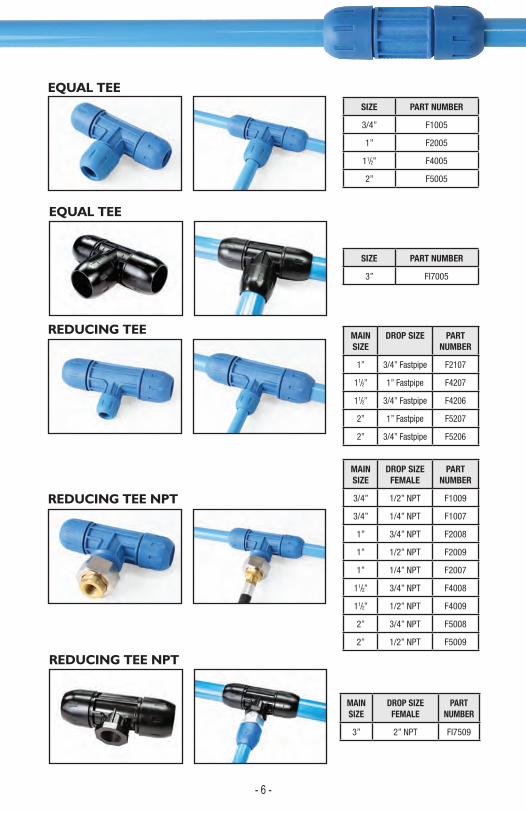
MAIN SIZE
DROP SIZEFEMALE
PART NUMBER
3” 2” NPT FI7509
EQUAL TEE
REDUCING TEE NPT
SIZE PART NUMBER
3/4” F1005
1” F2005
11/2” F4005
2” F5005
SIZE PART NUMBER
3” FI7005
MAIN SIZE
DROP SIZE PARTNUMBER
1” 3/4” Fastpipe F2107
11/2” 1” Fastpipe F4207
11/2” 3/4” Fastpipe F4206
2” 1” Fastpipe F5207
2” 3/4” Fastpipe F5206
MAIN SIZE
DROP SIZEFEMALE
PARTNUMBER
3/4” 1/2” NPT F1009
3/4” 1/4” NPT F1007
1” 3/4” NPT F2008
1” 1/2” NPT F2009
1” 1/4” NPT F2007
11/2” 3/4” NPT F4008
11/2” 1/2” NPT F4009
2” 3/4” NPT F5008
2” 1/2” NPT F5009
REDUCING TEE
REDUCING TEE NPT
EQUAL TEE
- 6 - - 7 -
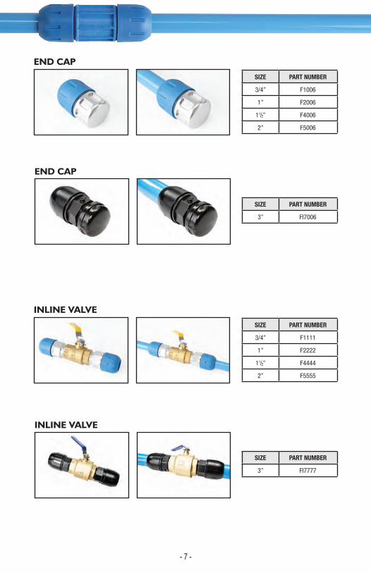
SIZE PART NUMBER
3/4” F1006
1” F2006
11/2” F4006
2” F5006
SIZE PART NUMBER
3” FI7006
SIZE PART NUMBER
3/4” F1111
1” F2222
11/2” F4444
2” F5555
SIZE PART NUMBER
3” FI7777
END CAP
INLINE VALVE
END CAP
INLINE VALVE
MAIN SIZE
DROP SIZE PARTNUMBER
1” 3/4” Fastpipe F2107
11/2” 1” Fastpipe F4207
11/2” 3/4” Fastpipe F4206
2” 1” Fastpipe F5207
2” 3/4” Fastpipe F5206

- 8 - - 9 -
SIZE MALETHREAD
PARTNUMBER
3/4” 1/2” NPT F1018
3/4” 3/4” NPT F1118
1” 1/2” NPT F2018
1” 3/4” NPT F2118
1” 1” NPT F2218
11/2” 11/2” NPT F4418
2” 11/2” NPT F5418
2” 2” NPT F5518
SIZE MALETHREAD
PARTNUMBER
3” 3” NPT FI7718
SIZE FEMALETHREAD
PARTNUMBER
3/4” 3/4” NPT F1120
1” 1” NPT F2220
11/2” 11/2” NPT F4420
THREADED MALE NIPPLE
THREADED FEMALE NIPPLE
THREADED MALE NIPPLE
- 8 - - 9 -
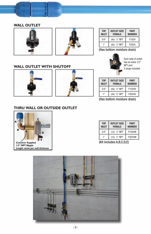
TOP INLET
OUTLET SIZEFEMALE
PARTNUMBER
3/4” (4x) 1/2” NPT F1024
1” (4x) 1/2” NPT F2024
TOP INLET
OUTLET SIZEFEMALE
PARTNUMBER
3/4” (4x) 1/2” NPT F1024V
1” (4x) 1/2” NPT F2024V
TOP INLET
OUTLET SIZEFEMALE
PARTNUMBER
3/4” (1x) 1/2” NPT F1024W
1” (1x) 1/2” NPT F2024W
A
Customer Supplied1/2” NPT NippleLength varies per wall thickness
B
C
D
E
WALL OUTLET
WALL OUTLET WITH SHUTOFF
THRU WALL OR OUTSIDE OUTLET
(Has bottom moisture drain)
Each side of outlet has an extra 1/2” NPT port 2 plugs included
(Has bottom moisture drain)
(Kit includes A,B,C,D,E)
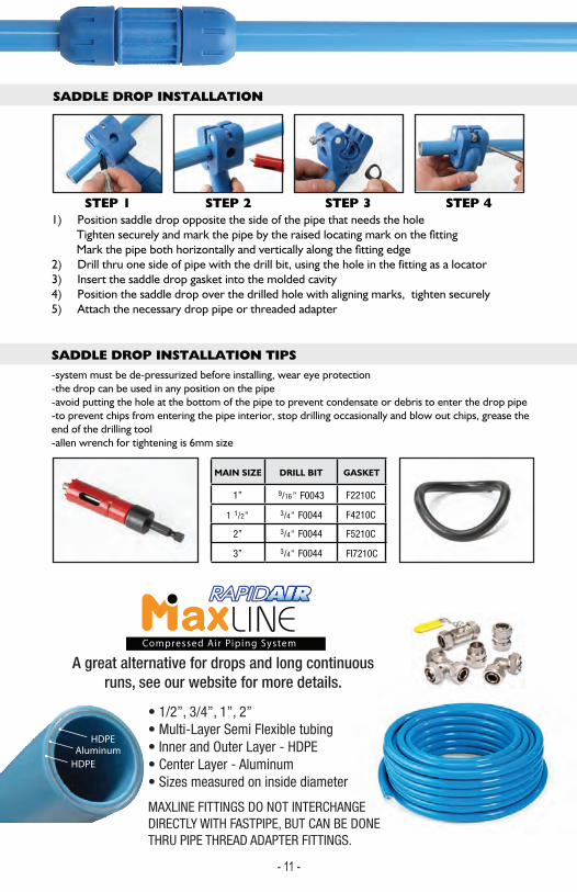
SADDLE DROP INSTALLATION
STEP 1 STEP 2 STEP 3 STEP 4
MAIN SIZE DRILL BIT GASKET
1” 9/16” F0043 F2210C
2” F5210C
1 1/2” 3/4” F0044
3/4”
3/4”
F0044
3” FI7210C F0044
F4210C
1) Position saddle drop opposite the side of the pipe that needs the hole
3) Insert the saddle drop gasket into the molded cavity2) Drill thru one side of pipe with the drill bit, using the hole in the fitting as a locator
4) Position the saddle drop over the drilled hole with aligning marks, tighten securely 5) Attach the necessary drop pipe or threaded adapter
Fastpipe 3” saddles are aluminum die cast and use a differentstyle compression nut and inner parts than the standard Fastpipe fittings.
SADDLE DROP INSTALLATION TIPS-system must be de-pressurized before installing, wear eye protection-the drop can be used in any position on the pipe-avoid putting the hole at the bottom of the pipe to prevent condensate or debris to enter the drop pipe-to prevent chips from entering the pipe interior, stop drilling occasionally and blow out chips, grease the end of the drilling tool-allen wrench for tightening is 6mm size
FITTINGS PARTS BREAKDOWNA) O-RING (Tension)B) BACKERC) SS BITE RINGD) COLLETE) O-RING (Sealing)F) CONE NUT
SPARE PARTS KIT (INCLUDES A,C AND E)SIZE PART NUMBER
1” FI2076
3/4” FI1076
A B C ED F
- 10 - - 11 -
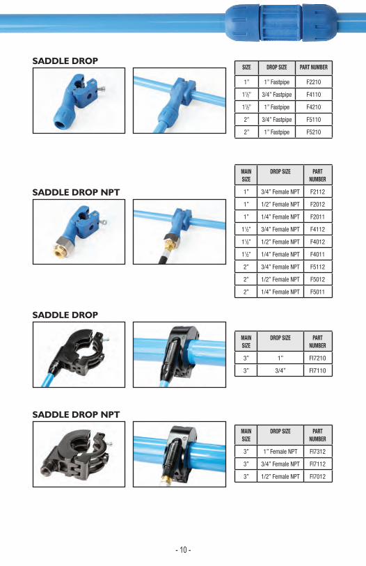
SIZE DROP SIZE PART NUMBER
1” 1” Fastpipe F2210
11/2” 3/4” Fastpipe F4110
11/2” 1” Fastpipe F4210
2” 3/4” Fastpipe F5110
2” 1” Fastpipe F5210
MAIN SIZE
DROP SIZE PART NUMBER
1” 3/4” Female NPT F2112
1” 1/2” Female NPT F2012
1” 1/4” Female NPT F2011
11/2” 3/4” Female NPT F4112
11/2” 1/2” Female NPT F4012
11/2” 1/4” Female NPT F4011
2” 3/4” Female NPT F5112
2” 1/2” Female NPT F5012
2” 1/4” Female NPT F5011
SADDLE DROP
SADDLE DROP NPT
MAIN SIZE
DROP SIZE PART NUMBER
3” 1” FI7210
3” 3/4” FI7110
MAIN SIZE
DROP SIZE PART NUMBER
3” 1” Female NPT FI7312
3” 3/4” Female NPT FI7112
3” 1/2” Female NPT FI7012
SADDLE DROP
SADDLE DROP NPT
SADDLE DROP INSTALLATION
STEP 1 STEP 2 STEP 3 STEP 4
MAIN SIZE DRILL BIT GASKET
1” 9/16” F0043 F2210C
2” F5210C
1 1/2” 3/4” F0044
3/4”
3/4”
F0044
3” FI7210C F0044
F4210C
1) Position saddle drop opposite the side of the pipe that needs the hole
3) Insert the saddle drop gasket into the molded cavity2) Drill thru one side of pipe with the drill bit, using the hole in the fitting as a locator
4) Position the saddle drop over the drilled hole with aligning marks, tighten securely 5) Attach the necessary drop pipe or threaded adapter
Fastpipe 3” saddles are aluminum die cast and use a differentstyle compression nut and inner parts than the standard Fastpipe fittings.
SADDLE DROP INSTALLATION TIPS-system must be de-pressurized before installing, wear eye protection-the drop can be used in any position on the pipe-avoid putting the hole at the bottom of the pipe to prevent condensate or debris to enter the drop pipe-to prevent chips from entering the pipe interior, stop drilling occasionally and blow out chips, grease the end of the drilling tool-allen wrench for tightening is 6mm size
FITTINGS PARTS BREAKDOWNA) O-RING (Tension)B) BACKERC) SS BITE RINGD) COLLETE) O-RING (Sealing)F) CONE NUT
SPARE PARTS KIT (INCLUDES A,C AND E)SIZE PART NUMBER
1” FI2076
3/4” FI1076
A B C ED F
- 10 - - 11 -
A great alternative for drops and long continuous runs, see our website for more details.
• 1/2”, 3/4”, 1”, 2”• Multi-Layer Semi Flexible tubing• Inner and Outer Layer - HDPE• Center Layer - Aluminum• Sizes measured on inside diameter
MAXLINE FITTINGS DO NOT INTERCHANGE DIRECTLY WITH FASTPIPE, BUT CAN BE DONE THRU PIPE THREAD ADAPTER FITTINGS.
FASTPIPE INSTALLATION STEPS
1) CUT PIPE TO LENGTH with tubing cutter (cut must be square) (DO NOT USE HACK SAW )
2) DEBURR the end of the pipe outside and inside
3) MARK END OF PIPE for the proper insertion depth
1” Fittings: 2-3/4 inches 3/4” Fittings: 2 inches
2” Fittings: 4-3/4 inches 3” Fittings: 4-1/2 inches
1-1/2” Fittings: 4 inches
4) WET END OF PIPE, with very diluted soapy water DO NOT USE ANY OIL OR GREASE LUBRICANT
5) LOOSEN FITTING CONE NUT PARTIALLY LOOK INSIDE EACH FITTING FOR INNER PARTS
(inner parts, o-ring, stainless steel bite ring)
6) INSERT PIPE HAND TIGHTEN FULLY TIGHTEN
FASTPIPE INSTALLATION GUIDELINES
-CHECK that all fittings are fully tightened before pressurizing the system for the first time. -for initial installation, pressurize system slowly to 50 psi and check for leaks, then pressurize slowly to MAX 190 psi
-Always use a filter unit to keep contaminants out of the FastPipe system.
-take extra precaution with END CAP INSTALLATION, double check these fittings are tightened fully.
-Assemble all NPT threads with two wraps of teflon tape and then PIPE SEALANT which prevents thread galling.
-FASTPIPE can be bent to conform around minor obstacles to a maximum of 15 degrees. DO NOT OVERBEND -USE JUMPER HOSE at the air compressor to absorb vibration -ONLY FastPipe outlets are designed for the direct pulling force of air hoses, for other FastPipe fittings attached to hoses, always secure hose with a STRAIN RELIEF, attached to the building structure
may have loosened due to settling of the component.
STEP 1
STEP 2
STEP 3
STEP 4
STEP 5
STEP 6
TAB MUST ALIGN TO NOTCH
-After the first 48-96 hours of operation, check all the joints. Then make sure all the cone nuts are tight as these
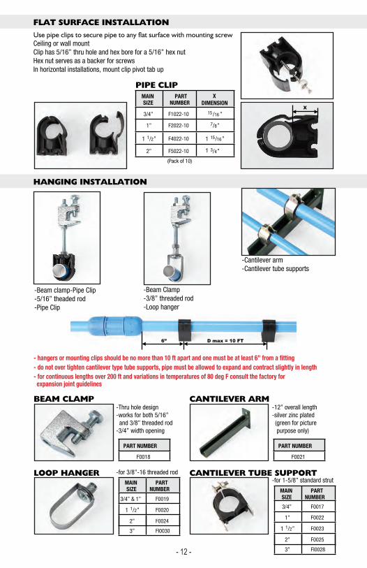
FLAT SURFACE INSTALLATION
Ceiling or wall mountClip has 5/16” thru hole and hex bore for a 5/16” hex nutHex nut serves as a backer for screwsIn horizontal installations, mount clip pivot tab up
-Beam clamp-Pipe Clip-5/16” theaded rod-Pipe Clip
-Thru hole design-works for both 5/16” and 3/8” threaded rod-3/4” width opening
-for 3/8”-16 threaded rod
-12” overall length-silver zinc plated (green for picture purpose only)
-for 1-5/8” standard strut
-Beam Clamp-3/8” threaded rod-Loop hanger
-Cantilever arm -Cantilever tube supports
HANGING INSTALLATION
X
6” D max = 10 FT
MAIN SIZE
PART NUMBER
X DIMENSION
3/4” F1022-10 15 /16 ”
1” F2022-10 7/8”
2” F5022-10 3/4”
1 1/2” F4022-10
(Pack of 10)
1
1
15/16”
PART NUMBER
F0018
PART NUMBER
F0021
MAIN SIZE
PART NUMBER
3/4” & 1” F0019
2” F0024
3” FI0030
1 1/2” F0020
MAIN SIZE
PART NUMBER
1” F0022
3/4” F0017
2” F0025
3” FI0028
1 1/2” F0023
BEAM CLAMP
PIPE CLIP
LOOP HANGER
CANTILEVER ARM
CANTILEVER TUBE SUPPORT
- hangers or mounting clips should be no more than 10 ft apart and one must be at least 6” from a fitting- do not over tighten cantilever type tube supports, pipe must be allowed to expand and contract slightly in length- for continuous lengths over 200 ft and variations in temperatures of 80 deg F consult the factory for expansion joint guidelines
- 12 - - 13 -

FASTPIPE INSTALLATION STEPS
1) CUT PIPE TO LENGTH with tubing cutter (cut must be square) (DO NOT USE HACK SAW )
2) DEBURR the end of the pipe outside and inside
3) MARK END OF PIPE for the proper insertion depth
1” Fittings: 2-3/4 inches 3/4” Fittings: 2 inches
2” Fittings: 4-3/4 inches 3” Fittings: 4-1/2 inches
1-1/2” Fittings: 4 inches
4) WET END OF PIPE, with very diluted soapy water DO NOT USE ANY OIL OR GREASE LUBRICANT
5) LOOSEN FITTING CONE NUT PARTIALLY LOOK INSIDE EACH FITTING FOR INNER PARTS
(inner parts, o-ring, stainless steel bite ring)
6) INSERT PIPE HAND TIGHTEN FULLY TIGHTEN
FASTPIPE INSTALLATION GUIDELINES
-CHECK that all fittings are fully tightened before pressurizing the system for the first time. -for initial installation, pressurize system slowly to 50 psi and check for leaks, then pressurize slowly to MAX 190 psi
-Always use a filter unit to keep contaminants out of the FastPipe system.
-take extra precaution with END CAP INSTALLATION, double check these fittings are tightened fully.
-Assemble all NPT threads with two wraps of teflon tape and then PIPE SEALANT which prevents thread galling.
-FASTPIPE can be bent to conform around minor obstacles to a maximum of 15 degrees. DO NOT OVERBEND -USE JUMPER HOSE at the air compressor to absorb vibration -ONLY FastPipe outlets are designed for the direct pulling force of air hoses, for other FastPipe fittings attached to hoses, always secure hose with a STRAIN RELIEF, attached to the building structure
may have loosened due to settling of the component.
STEP 1
STEP 2
STEP 3
STEP 4
STEP 5
STEP 6
TAB MUST ALIGN TO NOTCH
-After the first 48-96 hours of operation, check all the joints. Then make sure all the cone nuts are tight as these
FLAT SURFACE INSTALLATION
Ceiling or wall mountClip has 5/16” thru hole and hex bore for a 5/16” hex nutHex nut serves as a backer for screwsIn horizontal installations, mount clip pivot tab up
-Beam clamp-Pipe Clip-5/16” theaded rod-Pipe Clip
-Thru hole design-works for both 5/16” and 3/8” threaded rod-3/4” width opening
-for 3/8”-16 threaded rod
-12” overall length-silver zinc plated (green for picture purpose only)
-for 1-5/8” standard strut
-Beam Clamp-3/8” threaded rod-Loop hanger
-Cantilever arm -Cantilever tube supports
HANGING INSTALLATION
X
6” D max = 10 FT
MAIN SIZE
PART NUMBER
X DIMENSION
3/4” F1022-10 15 /16 ”
1” F2022-10 7/8”
2” F5022-10 3/4”
1 1/2” F4022-10
(Pack of 10)
1
1
15/16”
PART NUMBER
F0018
PART NUMBER
F0021
MAIN SIZE
PART NUMBER
3/4” & 1” F0019
2” F0024
3” FI0030
1 1/2” F0020
MAIN SIZE
PART NUMBER
1” F0022
3/4” F0017
2” F0025
3” FI0028
1 1/2” F0023
BEAM CLAMP
PIPE CLIP
LOOP HANGER
CANTILEVER ARM
CANTILEVER TUBE SUPPORT
- hangers or mounting clips should be no more than 10 ft apart and one must be at least 6” from a fitting- do not over tighten cantilever type tube supports, pipe must be allowed to expand and contract slightly in length- for continuous lengths over 200 ft and variations in temperatures of 80 deg F consult the factory for expansion joint guidelines
- 12 - - 13 -
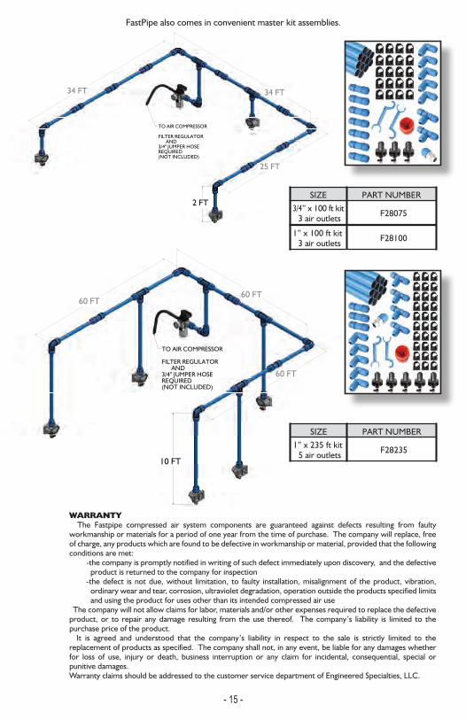
Depth mark for cutting location
60 FT60 FT
60 FT
10 FT
TO AIR COMPRESSOR
FILTER REGULATOR AND 3/4" JUMPER HOSE REQUIRED(NOT INCLUDED)
34 FT 34 FT
25 FT
2 FT
TO AIR COMPRESSOR
FILTER REGULATOR AND 3/4" JUMPER HOSE REQUIRED(NOT INCLUDED)
FastPipe also comes in convenient master kit assemblies.
SIZE PART NUMBER3/4” x 100 ft kit F280753 air outlets
SIZE PART NUMBER1” x 235 ft kit F282355 air outlets
WARRANTY The Fastpipe compressed air system components are guaranteed against defects resulting from faulty workmanship or materials for a period of one year from the time of purchase. The company will replace, free of charge, any products which are found to be defective in workmanship or material, provided that the following conditions are met:
-the company is promptly notified in writing of such defect immediately upon discovery, and the defective product is returned to the company for inspection
-the defect is not due, without limitation, to faulty installation, misalignment of the product, vibration, ordinary wear and tear, corrosion, ultraviolet degradation, operation outside the products specified limits and using the product for uses other than its intended compressed air use
The company will not allow claims for labor, materials and/or other expenses required to replace the defective product, or to repair any damage resulting from the use thereof. The company’s liability is limited to the purchase price of the product. It is agreed and understood that the company’s liability in respect to the sale is strictly limited to the replacement of products as specified. The company shall not, in any event, be liable for any damages whether for loss of use, injury or death, business interruption or any claim for incidental, consequential, special or punitive damages. Warranty claims should be addressed to the customer service department of Engineered Specialties, LLC.
1” x 100 ft kit F281003 air outlets
WARNINGS
-Compressed air is DANGEROUS if not used properly-Always use EYE PROTECTION when using compressed air-DO NOT POINT compressed air at your body or any person-Pressurize system SLOWLY -TURN OFF air compressor when not in use-CHECK local building codes before installation-CA PROP 65: This product contains chemicals known to the state of California to cause cancer and birth defects or other reproductive harm-ALWAYS RELIEVE the system pressure when installing or performing maintenance-Systems must have a SAFETY RELIEF valve installed at the
-Keep children away from the system
compressed air source to prevent over pressurization
exposure (Pipe needs no covering and can be exposed)
FastPipe is NOT designed: -for underground burial -to electrically ground equipment -to be welded -to take violent impacts -to be used where the compressed air temperature is above 140 deg F -for environments of caustic or corrosive chemicals
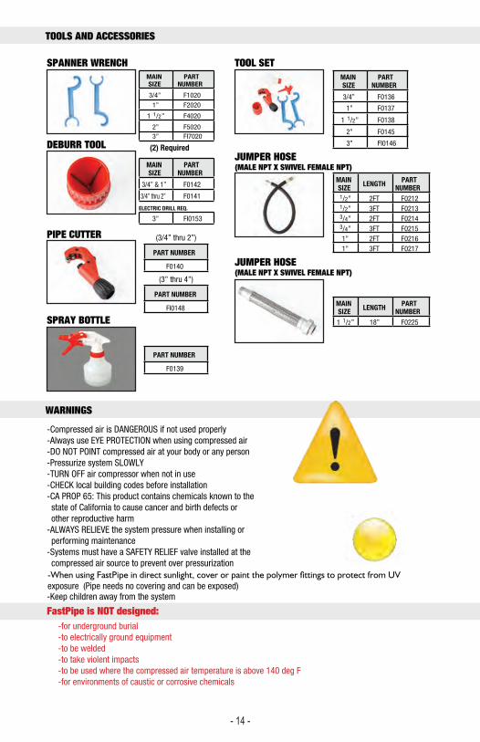
PART NUMBER
(3/4” thru 2”)
F0140
PART NUMBER
(3” thru 4”)
FI0148
PART NUMBER
F0139
MAIN SIZE
PART NUMBER
1” F0137
3/4” F0136
2” F0145
3” FI0146
1 1/2” F0138
MAIN SIZE
PART NUMBER
1” F2020
3/4” F1020
2” F5020
1 1/2” F4020
MAIN SIZE
PART NUMBER
3/4” & 1” F0142
3/4” thru 2” F0141
3” FI0153
MAIN SIZE LENGTH PART
NUMBER1/2” 2FT F02121/2” 3FT F02133/4” 2FT F02143/4” 3FT F02151” 2FT F02161” 3FT F0217
MAIN SIZE LENGTH PART
NUMBER
1 1/2” 18” F0225
SPANNER WRENCH
PIPE CUTTER
DEBURR TOOL
SPRAY BOTTLE
TOOL SET
JUMPER HOSE(MALE NPT X SWIVEL FEMALE NPT)
JUMPER HOSE(MALE NPT X SWIVEL FEMALE NPT)
3” FI7020
(2) Required
ELECTRIC DRILL REQ.
TOOLS AND ACCESSORIES
- 14 - - 15 -
60 FT60 FT
60 FT
10 FT
TO AIR COMPRESSOR
FILTER REGULATOR AND 3/4" JUMPER HOSE REQUIRED(NOT INCLUDED)
34 FT 34 FT
25 FT
2 FT
TO AIR COMPRESSOR
FILTER REGULATOR AND 3/4" JUMPER HOSE REQUIRED(NOT INCLUDED)
FastPipe also comes in convenient master kit assemblies.
SIZE PART NUMBER3/4” x 100 ft kit F280753 air outlets
SIZE PART NUMBER1” x 235 ft kit F282355 air outlets
WARRANTY The Fastpipe compressed air system components are guaranteed against defects resulting from faulty workmanship or materials for a period of one year from the time of purchase. The company will replace, free of charge, any products which are found to be defective in workmanship or material, provided that the following conditions are met:
-the company is promptly notified in writing of such defect immediately upon discovery, and the defective product is returned to the company for inspection
-the defect is not due, without limitation, to faulty installation, misalignment of the product, vibration, ordinary wear and tear, corrosion, ultraviolet degradation, operation outside the products specified limits and using the product for uses other than its intended compressed air use
The company will not allow claims for labor, materials and/or other expenses required to replace the defective product, or to repair any damage resulting from the use thereof. The company’s liability is limited to the purchase price of the product. It is agreed and understood that the company’s liability in respect to the sale is strictly limited to the replacement of products as specified. The company shall not, in any event, be liable for any damages whether for loss of use, injury or death, business interruption or any claim for incidental, consequential, special or punitive damages. Warranty claims should be addressed to the customer service department of Engineered Specialties, LLC.
1” x 100 ft kit F281003 air outlets
WARNINGS
-Compressed air is DANGEROUS if not used properly-Always use EYE PROTECTION when using compressed air-DO NOT POINT compressed air at your body or any person-Pressurize system SLOWLY -TURN OFF air compressor when not in use-CHECK local building codes before installation-CA PROP 65: This product contains chemicals known to the state of California to cause cancer and birth defects or other reproductive harm-ALWAYS RELIEVE the system pressure when installing or performing maintenance-Systems must have a SAFETY RELIEF valve installed at the
-Keep children away from the system
compressed air source to prevent over pressurization
exposure (Pipe needs no covering and can be exposed)
FastPipe is NOT designed: -for underground burial -to electrically ground equipment -to be welded -to take violent impacts -to be used where the compressed air temperature is above 140 deg F -for environments of caustic or corrosive chemicals
PART NUMBER
(3/4” thru 2”)
F0140
PART NUMBER
(3” thru 4”)
FI0148
PART NUMBER
F0139
MAIN SIZE
PART NUMBER
1” F0137
3/4” F0136
2” F0145
3” FI0146
1 1/2” F0138
MAIN SIZE
PART NUMBER
1” F2020
3/4” F1020
2” F5020
1 1/2” F4020
MAIN SIZE
PART NUMBER
3/4” & 1” F0142
3/4” thru 2” F0141
3” FI0153
MAIN SIZE LENGTH PART
NUMBER1/2” 2FT F02121/2” 3FT F02133/4” 2FT F02143/4” 3FT F02151” 2FT F02161” 3FT F0217
MAIN SIZE LENGTH PART
NUMBER
1 1/2” 18” F0225
SPANNER WRENCH
PIPE CUTTER
DEBURR TOOL
SPRAY BOTTLE
TOOL SET
JUMPER HOSE(MALE NPT X SWIVEL FEMALE NPT)
JUMPER HOSE(MALE NPT X SWIVEL FEMALE NPT)
3” FI7020
(2) Required
ELECTRIC DRILL REQ.
TOOLS AND ACCESSORIES
- 14 - - 15 -
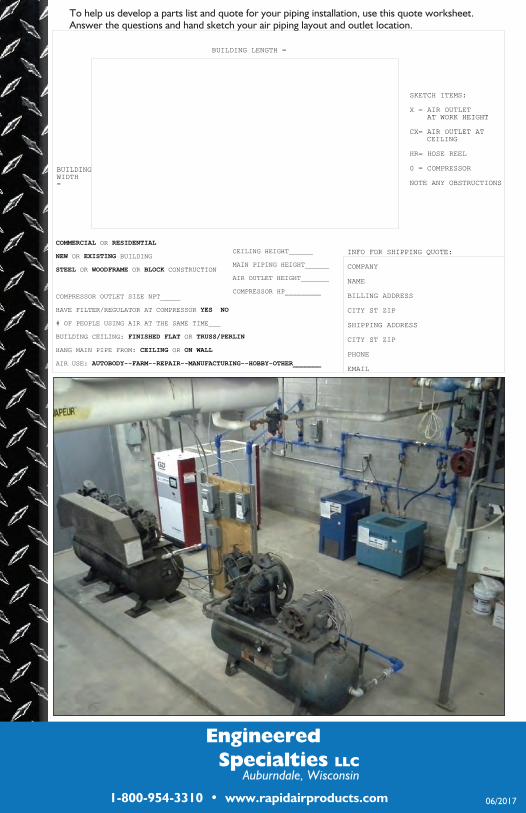
To help us develop a parts list and quote for your piping installation, use this quote worksheet.Answer the questions and hand sketch your air piping layout and outlet location.
06/2017
BUILDINGWIDTH=
BUILDING LENGTH =
COMMERCIAL OR RESIDENTIAL
NEW OR EXISTING BUILDING
STEEL OR WOODFRAME OR BLOCK CONSTRUCTION
COMPRESSOR OUTLET SIZE NPT_____
HAVE FILTER/REGULATOR AT COMPRESSOR YES NO
# OF PEOPLE USING AIR AT THE SAME TIME___
BUILDING CEILING: FINISHED FLAT OR TRUSS/PERLIN
HANG MAIN PIPE FROM: CEILING OR ON WALL
AIR USE: AUTOBODY--FARM--REPAIR--MANUFACTURING--HOBBY-OTHER_______
INFO FOR SHIPPING QUOTE:
COMPANY
NAME
BILLING ADDRESS
CITY ST ZIP
SHIPPING ADDRESS
CITY ST ZIP
PHONE
SKETCH ITEMS:
X = AIR OUTLET AT WORK HEIGHT
CX= AIR OUTLET ATCEILING
HR= HOSE REEL
0 = COMPRESSOR
NOTE ANY OBSTRUCTIONS
CEILING HEIGHT______
MAIN PIPING HEIGHT______
AIR OUTLET HEIGHT_______
COMPRESSOR HP_________
Engineered Specialties LLC
Auburndale, Wisconsin
1-800-954-3310 • www.rapidairproducts.com