Alfa Laval - MGA NVR · Alfa Laval FINAL DRAWINGS LIST CUSTOMER : SAMSUNG HEAVY INDUSTRIES CO.,...
83
Alfa Laval Korea Ltd. C.P.O. Box 4285, Seoul 100-642, Korea www.alfalaval.com Alfa Laval 수 신 : 삼 성 중 공 업㈜ / 완 종합설계(기술지원) 참 조 : 유 영 기 대리님 호 선 : H-1657 제 목 : : FINAL DWG FOR F.W GENERATOR (INCL. INSTRUCTION MANUAL) 1. 귀사의 일익 번창하심을 기원합니다. 2. 상기호선 관련하여, 요청하신 바와 같이 FINAL DRAWING (INCL.INSTRUCTION MANUAL) 5부 + CD 1장을 송부하오니 업무에 참조하시기 바랍니다. 3. 감사합니다. 한 국 알 파 라 발 (주) 2008년 02월 26일 모 영 환 / 박 용 민 드림
Transcript of Alfa Laval - MGA NVR · Alfa Laval FINAL DRAWINGS LIST CUSTOMER : SAMSUNG HEAVY INDUSTRIES CO.,...

Alfa Laval Korea Ltd. C.P.O. Box 4285, Seoul 100-642, Korea www.alfalaval.com
Alfa Laval
수 신 : 삼 성 중 공 업㈜ / 완성종합설계(기술지원) 참 조 : 유 영 기 대리님
호 선 : H-1657 제 목 : : FINAL DWG FOR F.W GENERATOR (INCL. INSTRUCTION MANUAL)
1. 귀사의 일익 번창하심을 기원합니다. 2. 상기호선 관련하여, 요청하신 바와 같이 FINAL DRAWING (INCL.INSTRUCTION
MANUAL) 5부 + CD 1장을 송부하오니 업무에 참조하시기 바랍니다. 3. 감사합니다.
한 국 알 파 라 발 (주)
2008년 02월 26일
모 영 환 / 박 용 민 드림
FINAL DRAWINGS WITH INSTRUCTION MANUAL
FOR FRESH WATER GENERATOR
HULL NO. : HN-1657
Hull No. HN1657
Ship Name WEST POLARIS
Ship Type 97,000 Drill Ship
IMO.No. 9372535
Electric format 1 CD
No. of copies 5 copy
CUSTOMER SAMSUNG HEAVY IND. CO., LTD.
DATE 080226

Alfa Laval
FINAL DRAWINGS LIST
CUSTOMER : SAMSUNG HEAVY INDUSTRIES CO., LTD.
HULL NO : H-1657
FWG Type : D-PU-2-36-CAS125
No Description Document No. Remark
1 Instruction manual -
2 Order specification -
3 General description, Freshwater Generator 985 20424
4 Technical data, Freshwater Generator 985 20427
5 Technical data, Pump and Motor 985 20461
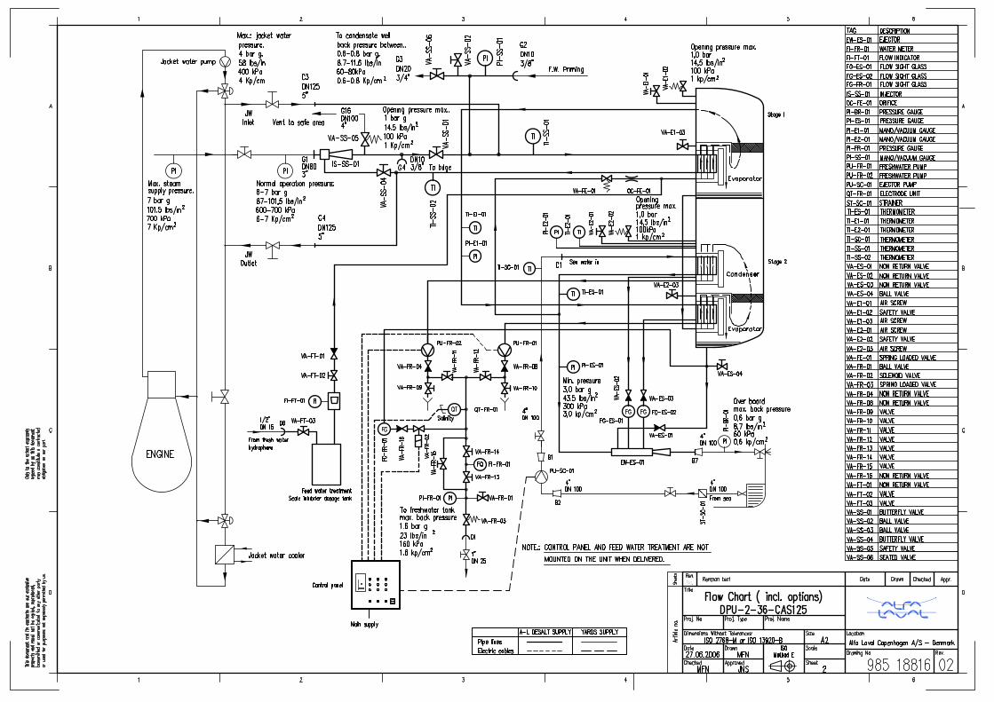
6 Flow chart, incl. options 985 18816
7 Dimension drawing, Freshwater Generator 985 17332
8 Frame Extension 985 20267
9 Nirex standard for holes in flanges 984 70193
10 Equipment specification 985 17326
11 Vertical plant positioning 985 17495
12 Assembly scheme 985 15915
13 Assembly drawing, Freshwater Pump 985 16684
14 Outline drawing, Motor for Freshwater Pump 985 16704
15 Dimension drawing, Control Panel build-on 985 17550
16 Technical data, Control Panel for Freshwater Generator 985 20435
17 Dimension drawing, Panel for Two-stage FWG 985 17585
18 Electric diagram, Panel for Two-stage FWG 985 17604
19 Feed water treatment - 130 Liter 985 17586
20 Feed water treatment mounting at right side 985 20131
21 List of loose supply items LOOSE
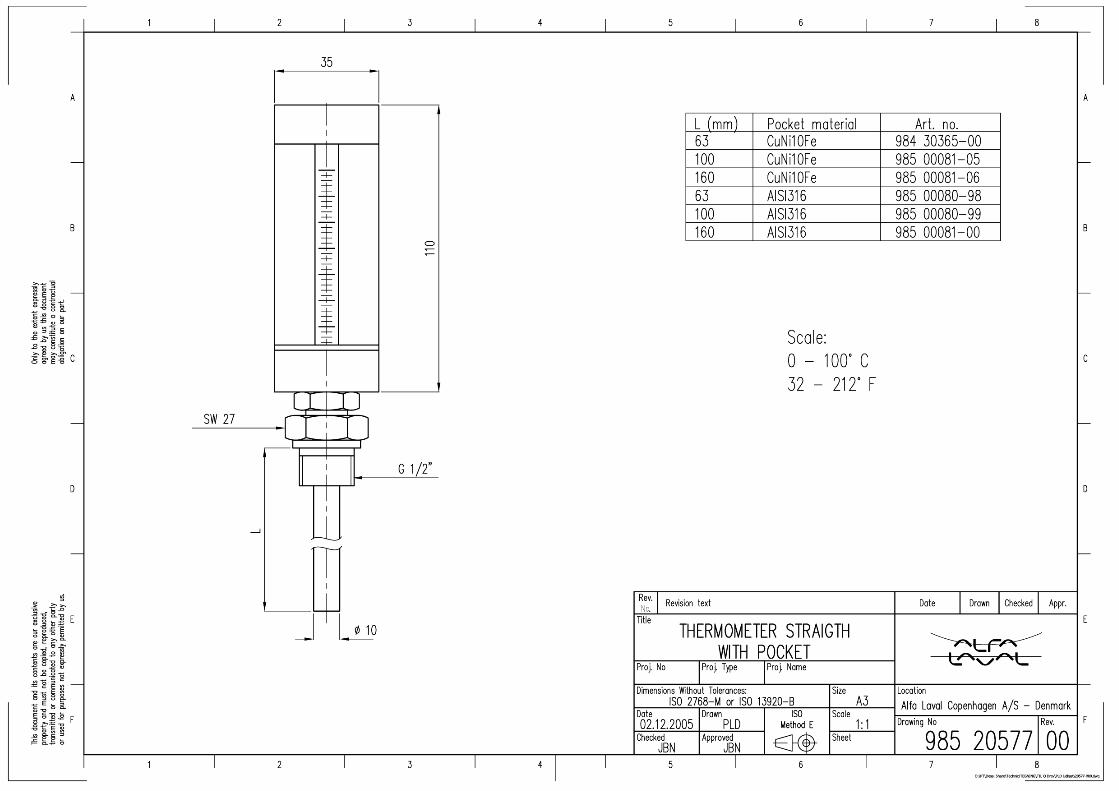
22 Dimension drawing, Thermometer 985 20577
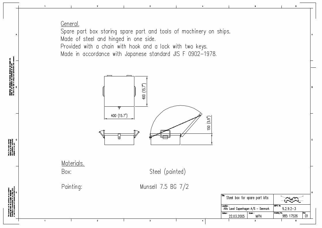
23 Steel box for spare part kits 985 17526
24 Standard spare parts for Freshwater Generator 985 20599
Dept Date Drawn Checked Approved
Marine & Diesel 2008-02-26 YMP YMP YHM

%RRN�1XPEHU��2��$�(���IP
,QVWUXFWLRQ�0DQXDOIRU�)UHVKZDWHU�*HQHUDWRU
7\SH�'�38������&$6�������
Serial No.: __________________
Shipname/ Hull No.: __________________
Customer: __________________

Alfa Laval reserve the right to make changes at any time without prior notice.
Any comments regarding possible errors and omissions or suggestions for improvement of this publication would be gratefully appreciated.
Copies of this publication can be ordered from your local Alfa Laval company.
3XEOLVKHG�E\� Alfa Laval Desalt A/SMaskinvej 5DK-2860 Søborg(Copenhagen) Denmark
© &RS\ULJKW�$OID�/DYDO�'HVDOW�This document and its content must not be copied, reproduced, transmitted or dis-closed to any third party without consent of Alfa Laval Desalt.
� O36A2E05.fm
7DEOH�RI�&RQWHQWV
6DIHW\�,QVWUXFWLRQV�DQG�:DUQLQJV
1.0.0 Safety Instructions and Warnings . . . . . . . . . . . . . . . . . . . . . . . . . . . . . . . . . page 5
6\VWHP�'HVFULSWLRQ
1.0.0 Working Principle . . . . . . . . . . . . . . . . . . . . . . . . . . . . . . . . . . . . . . . . . . . . . page 71.1.0 Freshwater Quality . . . . . . . . . . . . . . . . . . . . . . . . . . . . . . . . . . . . . . . . . . . . page 81.2.0 Main Components. . . . . . . . . . . . . . . . . . . . . . . . . . . . . . . . . . . . . . . . . . . . . page 81.3.0 Alternative Steam . . . . . . . . . . . . . . . . . . . . . . . . . . . . . . . . . . . . . . . . . . . . . page 9
2SHUDWLQJ�,QVWUXFWLRQV
1.0.0 Starting and Stopping Procedure . . . . . . . . . . . . . . . . . . . . . . . . . . . . . . . . . page 111.1.0 Starting-up the Plant with Jacket Cooling Water Heating . . . . . . . . . . . . . . . page 111.1.1 Evaporation . . . . . . . . . . . . . . . . . . . . . . . . . . . . . . . . . . . . . . . . . . . . . . . . . page 111.1.2 Condensation . . . . . . . . . . . . . . . . . . . . . . . . . . . . . . . . . . . . . . . . . . . . . . . . page 121.2.0 Adjustment of Jacket Water Flow . . . . . . . . . . . . . . . . . . . . . . . . . . . . . . . . . page 121.3.0 Adjustment of Sea Cooling Water. . . . . . . . . . . . . . . . . . . . . . . . . . . . . . . . . page 131.4.0 Stopping the Plant . . . . . . . . . . . . . . . . . . . . . . . . . . . . . . . . . . . . . . . . . . . . page 132.0.0 Before Starting Up the Plant with Steam Injection Equipment . . . . . . . . . . . page 142.1.0 Starting Up the Plant with Steam Injection Equipment (AS) . . . . . . . . . . . . . page 152.1.1 Evaporation . . . . . . . . . . . . . . . . . . . . . . . . . . . . . . . . . . . . . . . . . . . . . . . . . page 152.1.2 Condensation . . . . . . . . . . . . . . . . . . . . . . . . . . . . . . . . . . . . . . . . . . . . . . . . page 162.2.0 Adjustment of the Freshwater Production. . . . . . . . . . . . . . . . . . . . . . . . . . . page 162.3.0 Stopping the Plant Working with Steam Injection Heating . . . . . . . . . . . . . . page 162.4.0 Changing from Steam Injection Heating to Jacket Cooling Water . . . . . . . . page 172.5.0 Long Term Standstill. . . . . . . . . . . . . . . . . . . . . . . . . . . . . . . . . . . . . . . . . . . page 18
0DLQWHQDQFH
1.0.0 Why you need to perform regular maintenance duties . . . . . . . . . . . . . . . . . page 191.1.0 Overhaul Intervals. . . . . . . . . . . . . . . . . . . . . . . . . . . . . . . . . . . . . . . . . . . . . page 191.2.0 Maintenance of Separator Vessel. . . . . . . . . . . . . . . . . . . . . . . . . . . . . . . . . page 201.3.0 Maintenance of Evaporator Section . . . . . . . . . . . . . . . . . . . . . . . . . . . . . . . page 211.4.0 Maintenance of Condenser Section . . . . . . . . . . . . . . . . . . . . . . . . . . . . . . . page 221.5.0 Renewal of Plate Heat Exchanger Gaskets . . . . . . . . . . . . . . . . . . . . . . . . . page 231.5.1 Removal of Old Gaskets . . . . . . . . . . . . . . . . . . . . . . . . . . . . . . . . . . . . . . . page 231.5.2 Cleaning . . . . . . . . . . . . . . . . . . . . . . . . . . . . . . . . . . . . . . . . . . . . . . . . . . . . page 241.5.3 Preparation of new Gaskets . . . . . . . . . . . . . . . . . . . . . . . . . . . . . . . . . . . . page 241.5.4 Fitting new Gaskets . . . . . . . . . . . . . . . . . . . . . . . . . . . . . . . . . . . . . . . . . . . page 24
3UHVVXUH�7HVW
1.0.0 Pressure Testing Separator . . . . . . . . . . . . . . . . . . . . . . . . . . . . . . . . . . . . . page 27
O36A2E05TOC.fm �
7DEOH�RI�&RQWHQWV
&KHPLFDO�'RVLQJ�RI�6FDOH�&RQWURO�&KHPLFDOV
1.0.0 Prevention of Scaling. . . . . . . . . . . . . . . . . . . . . . . . . . . . . . . . . . . . . . . . . . page 291.1.0 Feed Water Ratio. . . . . . . . . . . . . . . . . . . . . . . . . . . . . . . . . . . . . . . . . . . . . page 291.2.0 Chemical Dosage . . . . . . . . . . . . . . . . . . . . . . . . . . . . . . . . . . . . . . . . . . . . page 291.2.1 Scale Inhibitor Dosage Equipment for Feed Water . . . . . . . . . . . . . . . . . . page 301.2.2 Safety Precautions with the use of Chemicals . . . . . . . . . . . . . . . . . . . . . . page 31
7URXEOH�6KRRWLQJ
1.0.0 Test Sheet . . . . . . . . . . . . . . . . . . . . . . . . . . . . . . . . . . . . . . . . . . . . . . . . . . page 331.1.0 Trouble Shooting Table . . . . . . . . . . . . . . . . . . . . . . . . . . . . . . . . . . . . . . . . page 33
0DLQWHQDQFH�RI�)UHVKZDWHU�3XPS
1.0.0 Maintenance of Freshwater Pump Types PVVF 1525-1532-2040 . . . . . . . page 371.1.0 Overhaul of the Pump . . . . . . . . . . . . . . . . . . . . . . . . . . . . . . . . . . . . . . . . . page 371.1.1 Clearance . . . . . . . . . . . . . . . . . . . . . . . . . . . . . . . . . . . . . . . . . . . . . . . . . . page 381.1.2 Dismantling Pump Shaft . . . . . . . . . . . . . . . . . . . . . . . . . . . . . . . . . . . . . . . page 38
0DLQWHQDQFH�RI�(MHFWRU�3XPS
1.0.0 Maintenance of Ejector Pump . . . . . . . . . . . . . . . . . . . . . . . . . . . . . . . . . . . page 411.1.0 Overhaul of the Pump . . . . . . . . . . . . . . . . . . . . . . . . . . . . . . . . . . . . . . . . . page 411.1.1 Clearance . . . . . . . . . . . . . . . . . . . . . . . . . . . . . . . . . . . . . . . . . . . . . . . . . . page 421.1.2 Dismantling Pump Shaft . . . . . . . . . . . . . . . . . . . . . . . . . . . . . . . . . . . . . . . page 44
6DOLQRPHWHU
1.0.0 Salinometer Type DS-20 . . . . . . . . . . . . . . . . . . . . . . . . . . . . . . . . . . . . . . . page 451.1.0 Technical Specification . . . . . . . . . . . . . . . . . . . . . . . . . . . . . . . . . . . . . . . . page 451.2.0 Installation (for DS-20). . . . . . . . . . . . . . . . . . . . . . . . . . . . . . . . . . . . . . . . . page 451.3.0 Instructions for use . . . . . . . . . . . . . . . . . . . . . . . . . . . . . . . . . . . . . . . . . . . page 461.3.1 Testing the Instrument . . . . . . . . . . . . . . . . . . . . . . . . . . . . . . . . . . . . . . . . page 461.3.2 Adjustment of Alarm Level . . . . . . . . . . . . . . . . . . . . . . . . . . . . . . . . . . . . . page 461.3.3 Maintenance . . . . . . . . . . . . . . . . . . . . . . . . . . . . . . . . . . . . . . . . . . . . . . . . page 47
6SDUH�3DUWV
1.0.0 Ordering Spare Parts. . . . . . . . . . . . . . . . . . . . . . . . . . . . . . . . . . . . . . . . . . page 491.1.0 Alfa Laval Service . . . . . . . . . . . . . . . . . . . . . . . . . . . . . . . . . . . . . . . . . . . . page 49
,QGH[
� O36A2E05TOC.fm

6DIHW\�,QVWUXFWLRQV�DQG�:DUQLQJV
Should you need further clarification regarding this manual, do not hesitate to con-tact your local Alfa Laval representative - or call Alfa Laval Desalt directly.
����� 6DIHW\�,QVWUXFWLRQV�DQG�:DUQLQJV
The following symbols in this manual point out safety precautions. It means your at-tention is needed and your safety is involved.
,W�LV�WKH�RZQHU¶V�DQG�RSHUDWRU¶V�UHVSRQVLELOLW\�WR�VHH�WKDW�DQ\�SHUVRQ�LQYROYHG�ZLWK�WKH�XVH�RU�RSHUDWLRQ�RI�WKLV�HTXLSPHQW�IROORZ�DOO�VDIHW\�LQVWUXFWLRQV�
5HDG�DOO�VDIHW\�LQVWUXFWLRQV�FDUHIXOO\�DQG�LQVLVW�WKDW�WKH\�ZLOO�EH�IROORZHG�E\�WKRVH�ZRUNLQJ�ZLWK�\RX�DQG�IRU�\RX��1RW�IROORZLQJ�WKH�LQVWUXFWLRQV�PD\�FDXVH�VHYHUH�SHUVRQDO�LQMXU\�RU�GDPDJH�WKH�HTXLSPHQW�EH\RQG�UHSDLU�
'R�QRW�DOORZ�WKLV�HTXLSPHQW�WR�EH�XVHG�LI�LW�LV�IDXOW\�RU�WKH�RSHUDWRU�GRHV�QRW�XQGHUVWDQG�WKH�SURSHU�XVH�
7HOHSKRQH +45 (for Denmark) 39 53 60 00
7HOHID[ +45 (for Denmark) 39 53 65 66
:$51,1*
This symbol is used to indicate the presence of a hazard which can or will cause severe personal injury, if the warning is ignored.
&$87,21
Certain passages of the text will be marked with a caution mark. This mark indicates the presence of hazard which will or can cause property damage if the instructions are not observed.
127(
This type of instruction indicates a situation which, if not avoided, could re-sult in damage to the equipment.
Samare04.fm �

6DIHW\�,QVWUXFWLRQV�DQG�:DUQLQJV
Freshwater must not be produced from polluted water, as the produced water can be unsuitable for human consumption.
If manuals are translated to local language the unit comply with the EEC Machinery Directive and EN 292-1/2 standards. For EEC land installations manuals MUST be available in local language before installing and operating the unit.
The unit also comply with EN 50081-2 and EN 50082-2 “Industry” with regards to the EMC directive from EEC.
:$51,1*
The freshwater generator is not to be operated in polluted water or within 20 miles from the coast
:$51,1*
1RLVH KD]DUGV• Use ear protection in noisy environments.
&UXVK KD]DUGV• Use correct lifting tools.• Do not work under hanging load.
%XUQ KD]DUG• Wear gloves to avoid burns by hot surfaces.
&XW KD]DUGV• Wear gloves to avoid cuts by sharp edges when handling machined
parts.• Wear helmet to avoid cuts by sharp edges during maintenance of the
equipment.
127(
• Max. ambient temperature for the equipment is 50°C (122°F).• Min. ambient temperature for the equipment is 0°C (32°F).
� Samare04.fm

6\VWHP�'HVFULSWLRQ
����� :RUNLQJ�3ULQFLSOH
The combined brine/air ejector driven by the ejector pump creates a vacuum in the system in order to lower the evaporation temperature of the feedwater.
The feedwater is introduced into the evaporator section stage 1 through an orifice,and is distributed into every second plate channel (evaporation channels).
The hot water is distributed into the remaining channels, thus transferring its heat to the feedwater in the evaporation channels.
Having reached boiling temperature - which is lower than at atmospheric pressure the feed water undergoes a partial evaporation, and the mixture of generated vapour and brine enters the separator vessel, where the brine is separated from the vapour and is introduced into every second channels of the evaporator stage 2 as feed wa-ter.
The vacuum steam generated in the first stage passes via a demister into theremaining channels in stage 2 of the evaporator section.
Ste
am fr
om s
tage
1 to
2Fresh water out
Sea cooling water in
Sea cooling water out
Jacket water in
Feed water stage 1 in
Feed water stage 2 in
Jacket water out
Sy2ase00.fm �

6\VWHP�'HVFULSWLRQ
Transferring its heat contents to the feedwater of the second stage, the vacuum steam condenses and is extracted by one of the freshwater extraction- and transfer pumps.
The brine from the second stage is extracted by the combined brine/air ejector.
The vacuum steam generated in the second stage passes via a demister into every second plate channel of the condenser section of the second stage.
The seawater supplied by the ejector pump is distributed into the remaining chan-nels, thus absorbing the heat being transferred from the condensing vapour.
The produced freshwater is extracted by the freshwater pump and led to the fresh-water tank.
����� )UHVKZDWHU�4XDOLW\
To continuously check the quality of the produced freshwater, a salinometer is pro-vided together with an electrode unit fitted on the freshwater pump delivery side.
If the salinity of the produced freshwater exceeds the chosen maximum value, the dump valve and alarm are activated to automatically dump the produced freshwater to the bilge.
If there are no special requirements from the authorities, the produced freshwater can be used directly as drinking water.
����� 0DLQ�&RPSRQHQWV
The freshwater generator consists of the following components:
1. (YDSRUDWRU VHFWLRQ The evaporator section consists of a plate heat exchanger and is enclosed in the separator vessel.
2. 6HSDUDWRU YHVVHO The separator separates the brine from the vapour.
3. &RQGHQVHU VHFWLRQ Just like the evaporator section the condenser section consists of a plate heat exchanger enclosed in the separator vessel.
4. &RPELQHG EULQH�DLU�HMHFWRU The ejector extracts brine and incondensable gases from the separator vessel.
5. (MHFWRU SXPS The ejector pump is a single-stage centrifugal pump. This pump supplies the condenser with sea water and the brine/air ejector with jet water as well as feed water for evaporation.
� Sy2ase00.fm
6\VWHP�'HVFULSWLRQ
6. )UHVKZDWHU SXPS The freshwater pump is a single-stage centrifugal pump. The freshwater pump extracts the produced freshwater from the condenser, and pumps the water to the freshwater tank.
7. 6DOLQRPHWHU The salinometer continuously checks the salinity of the produced water. The alarm set point is adjustable.
8. &RQWURO SDQHO Normally, the control panel is delivered by Alfa Laval Desalt A/S. It contains mo-tor starters, running lights, salinometer, contacts for remote alarm and is pre-pared for start/stop.
����� $OWHUQDWLYH�6WHDP
1. 6WHDP LQMHFWRUInstead of jacket cooling water heating, saturated live steam can alternatively be used as heating medium for the freshwater generator. In the steam injector the steam transfers partly heat, partly kinetic energy to the circulating water.
The condensate produced in this circuit is transferred to the condensate well through G3.
2. 6DIHW\ YDOYHIf the pressure after the steam injector exceeds 1 bar g the safety valve will open to secure the vessel.
3. 6WHDP TXDOLW\The steam supplied to the steam injector must be saturated steam.
Sy2ase00.fm �

6\VWHP�'HVFULSWLRQ
�� Sy2ase00.fm

2SHUDWLQJ�,QVWUXFWLRQV
Freshwater must not be produced from polluted water, as the produced water will be unsuitable for human consumption.
����� 6WDUWLQJ�DQG�6WRSSLQJ�3URFHGXUH
Please refer to PI-diagram (see “FWG Order Specification”).
����� 6WDUWLQJ�XS�WKH�3ODQW�ZLWK�-DFNHW�&RROLQJ�:DWHU�+HDWLQJ
1. Open valves on the suction and discharge side of the ejector pump PU-SC-01.
2. Open overboard valve for combined brine/air ejector.
3. Close DLU�VFUHZ�9$�(���� on the separator.
4. Start HMHFWRU�SXPS�38�6&��� to create a vacuum of min. 90%.
Pressure at combined brine/air ejector inlet minimum 300 kPa(3.0 kp/cm²).
Back pressure at combined brine/air ejector outlet maximum 60 kPa(0.6 kp/cm²).
����� (YDSRUDWLRQ
When there is a minimum of 90% vacuum (after maximum 10 minutes),
:$51,1*
DO NOT operate the plant in polluted water.
&$87,21
Before starting up please observe instructions for feedwater treatment, see “Chemical dosing of scale control chemicals”.
Opase00.fm ��

2SHUDWLQJ�,QVWUXFWLRQV
5. Close the two butterfly YDOYHV�in the steam injector circuit.
6. Open valve for feedwater treatment, if any.
7. Open hot water inlet and outlet valves.
8. Start hot water supply to distiller by adjusting bypass valve step-wise 10°C, until the desired jacket water temperature is reached.
The boiling temperature now rises, while the obtained vacuum drops to approx. 85%.
This indicates that evaporation has started.
����� &RQGHQVDWLRQ
After approx. 3 minutes the boiling temperature will drop again, and normal vacuum is reestablished.
9. Open valve to freshwater tank.
10. Switch on salinometer.
11. Start IUHVKZDWHU�SXPS�38�)5����38�)5���.
����� $GMXVWPHQW�RI�-DFNHW�:DWHU�)ORZ
Please refer to “FWG Order Specification” for specified hot water flow.
In order to obtain the specified flow of hot water, it is necessary to adjust the bypass
&$87,21
To secure that the boiler water and the jacket water do not mix the two but-terfly�YDOYHV�in the steam injector circuit�must be closed.
127(
The freshwater pump pressure must be between 120 and 160 kPa (1.2 - 1.6 kp/cm²).
�� Opase00.fm

2SHUDWLQJ�,QVWUXFWLRQV
valve until desired flow is achieved.
The flow can be calculated as follows:
MJW = KJW × cap.m³/24h =m³/h ∆tJW
Where:
MJW = Flow of hot water in one hour.
KJW = Constant=26.67 for 1-stage freshwater generator= Constant =15.52 for 2-stage freshwater generator
∆t = Difference in temperature of hot water in and out.
Cap.m³/24h = Freshwater production in 24 hours, i.e. production in 5min.times 288.
Example: cap. m³/24h = 20m³ TSW = 32°C
∆tJW = 6°C
1-stage freshwater generator MJW = 26.67 x 20 ................= 89 m³/h 6
����� $GMXVWPHQW�RI�6HD�&RROLQJ�:DWHU
The sea cooling water flow is correct, when the pressure at the inlet of the combined brine/air ejector is between 300 and 400 kPa (3.0 - 4.0 kp/cm².).
����� 6WRSSLQJ�WKH�3ODQW
1. Stop hot water supply to distiller.
2. Close valve for feedwater treatment, if any.
3. Stop IUHVKZDWHU�SXPS�38�)5����38�)5����
4. Switch off salinometer.
5. Stop HMHFWRU�SXPS�38�6&����
Opase00.fm ��
2SHUDWLQJ�,QVWUXFWLRQV
6. Open DLU�VFUHZ�9$�(�����
7. Close inlet and outlet valves for ejector pump.
8. Close overboard valve for combined brine/air ejector.
9. Close the valve to fresh water tank.
����� %HIRUH�6WDUWLQJ�8S�WKH�3ODQW�ZLWK�6WHDP�,QMHFWLRQ�(TXLSPHQW
When changing from jacket water heating to steam injection heating
1. Close in- and outlet valves for jacket cooling water system (yard supply)
2. Empty the jacket cooling water by G4 to the bilge
3. Open the plug at G2.
4. When empty: close the outlet G4
To fill up the steam injection system with clean fresh water or steam condensate.
5. Open the two butterfly YDOYHV�in the steam injector circuit
6. Fit a water hose into *�.
7. Fill up the system, with boiler feed water or clean fresh water until water escape from ball valve at the steam condensate outlet G3.
8. Then close this valve.
9. Dismantle the water hose.
&$87,21
All valves must be shut, while the generator is out of operation. Except air screw.
:$51,1*
The steam arrangement must be filled with fresh water from hydrophone system, before steam is supplied to the system.
�� Opase00.fm
2SHUDWLQJ�,QVWUXFWLRQV
10. Close the G2 with a plug.
����� 6WDUWLQJ�8S�WKH�3ODQW�ZLWK�6WHDP�,QMHFWLRQ�(TXLSPHQW��$6�
1. Open valves on the suction and discharge side of the combined HMHFWRU�FRRO�LQJ�ZDWHU�SXPS�38�6&����
2. Open overboard valve for FRPELQHG�EULQH�DLU�HMHFWRU�(:�(6����
3. Close DLU�VFUHZ�9$�(�����on the separator.
4. Start FRPELQHG�HMHFWRU�FRROLQJ�ZDWHU�SXPS�38�6&��� to create a vacuum of min. 90%.
Pressure at combined brine/air ejector inlet minimum 300 kPa (3.0 kp/cm²).
Back pressure at combined brine/air ejector outlet maximum 60 kPa (0.6 kp/cm²).
����� (YDSRUDWLRQ
5. Open the two butterfly valves in the steam injector circuit.
6. Open valve for feedwater treatment, if any.
7. Open the steam inlet valve (yard supply) slowly.
8. Wait a few minutes until the equipment will be noiseless.
9. Continue the supply of steam until the desired inlet pressure is reached. Steam pressure must be in accordance with pressure stated in “Technical specifica-tion”.
:$51,1*
No valve at all must be fitted on the pipe from the safety valve (G16) as this pipe must be open to the atmospheric pressure.
:$51,1*
Max. back pressure in condensate discharge line is 80 kPa (0.8 kp/cm²).
Opase00.fm ��
2SHUDWLQJ�,QVWUXFWLRQV
����� &RQGHQVDWLRQ
10. Open valve to freshwater tank.
11. Switch on salinometer.
12. Start IUHVKZDWHU�H[WUDFWLRQ�WUDQVIHU�SXPS�38�)5����38�)5����
13. Readjust the steam supply to reach the freshwater production.
����� $GMXVWPHQW�RI�WKH�)UHVKZDWHU�3URGXFWLRQ
The freshwater production can be regulated by adjustment of the quantity of steam supplied to the steam injector.
The steam inlet pressure corresponding to the production of fresh water in question can be regulated either by means of a manually operated regulating valve (yard sup-ply) or by an automatic reduction valve (yard supply).
Steam pressure must be in accordance with pressure stated in “FWG Order Speci-fication”.
����� 6WRSSLQJ�WKH�3ODQW�:RUNLQJ�ZLWK�6WHDP�,QMHFWLRQ�+HDWLQJ
1. Close steam inlet valve (yard supply).
2. Close valve for feedwater treatment, if any
127(
The freshwater pump pressure must be between 120 and 160 kPa (1.2 - 1.6 kp/cm²).
:$51,1*
Do not open steam inlet valve for the steam injector before the ejector pump PU-SC-01 has been started and serves feed water to the evaporator.
�� Opase00.fm
2SHUDWLQJ�,QVWUXFWLRQV
3. Stop IUHVKZDWHU�SXPS�38�)5����38�)5����
4. Switch off salinometer.
5. Stop HMHFWRU�SXPS�38�6&����
6. Open DLU�VFUHZ�9$�(�����
7. Close inlet and outlet valves for ejector pump.
8. Close overboard valve for combined brine/air ejector.
9. Close the valve to fresh water tank.
����� &KDQJLQJ�IURP�6WHDP�,QMHFWLRQ�+HDWLQJ�WR�-DFNHW�&RROLQJ�:DWHU
1. Close the valve for steam supply (yard supply).
2. Close the two butterfly valves for VWHDP�LQMHFWLRQ�HTXLSPHQW�
3. Open the ball valve at the steam condensate outlet G3.
4. Empty the boiler water by G4 to the bilge.
5. When empty: Close the outlet G4.
6. Close the ball valve mentioned above.
7. Open the valves for in- and outlet jacket cooling water to the evaporator (yard supply).
8. Start hot water supply to distiller by adjusting bypass valve step-wise until the desired jacket water temperature is reached.
&$87,21
When stopping the plant always check that the steam inlet valve is com-pletely closed.
This to avoid high temperature in the evaporator, as this might cause:
• Scale formation on the inside of the heat exchanger plates.
• Damage the gaskets in the heat exchanger.
Opase00.fm ��

2SHUDWLQJ�,QVWUXFWLRQV
����� /RQJ�7HUP�6WDQGVWLOO
If the distiller is out of operation for periods longer than 14 days, please observe “Maintenance of separator vessel”.
�� Opase00.fm
0DLQWHQDQFH
����� :K\�\RX�QHHG�WR�SHUIRUP�UHJXODU�PDLQWHQDQFH�GXWLHV
Regular maintenance of the plant will improve performance and availability.
The maintenance schedule on the following pages will tell you how often service should be performed on the main components.
As the actual operating conditions of the plant are of major influence on the life time, the overhaul dates are not obligatory but only recommended intervals.
When the plant has been in operation for a longer period of time and experience has been established as to the actual performance, it will be possible to adapt the main-tenance schedule.
For service on minor components please refer to component instructions.
����� 2YHUKDXO�,QWHUYDOV
&RPSRQHQW 2SHUDWLQJ�+RXUV
$FWLRQ
Evaporator section As required Clean in inhibited acid bath
Condenser section As required Clean with pure freshwater and brush
Combined ejector/cooling water pump with motor
8000 h Measure seal ring and impeller. Examine mechanical shaft seal, cooling water pipe passage. Megger-test electric motor. Clean pump thoroughly before reassembly.
Freshwater extraction pump with motor
8000 h See above
Combined air/brine ejector 8000 h Measure nozzles and diffuser and compare to measurements in technical specification.
MV-valves 4000 h Disassembly and inspect for damage.
Demister 8000 h Clean in inhibited acid bath
Madpue01.fm ��
0DLQWHQDQFH
����� 0DLQWHQDQFH�RI�6HSDUDWRU�9HVVHO
The separator vessels and the pressure plates for the heat exchanger sections (evaporator and condenser) are made of stainless steel with a special chemical treatment. This treatment will reestablish normal surface oxidation after work- up at the factory. The preparation is a natural protection of the stainless steel.
Further, there are isolating layers on the separator inside walls, where the heat ex-changer sections are mounted.
Whenever the sections are dismantled, these isolating layers must be checked for defects. Repair any defects according to the maintenance guide for glass flake coat-ing.
Whenever the separator vessel is opened,
• check that the anodes are functioning
If the anodes are not functioning and/or worn, replace them.
Manometers 8000 h Adjust with control manometer
Salinometer See separate in-structions
See separate instructions
&$87,21
To preserve this natural protection DO NOT scrape or scratch the inside surface of the separator vessels.
127(
If the unit is stopped for a longer period than 14 days.
• Open separator covers and clean unit inside with freshwater.
• Let the unit dry out completely, before closing covers.
&RPSRQHQW 2SHUDWLQJ�+RXUV
$FWLRQ
�� Madpue01.fm

0DLQWHQDQFH
����� 0DLQWHQDQFH�RI�(YDSRUDWRU�6HFWLRQ
Clean evaporator as follows:
1. Remove bolts in front cover, and open.
2. Loosen the 6 nuts in plate stack gradually, so that no nut is carrying the entire load alone
3. Remove plate stack.
4. Submerge plates completely in a hot, inhibited acid bath at maximum 50ºC. For further instructions see “Chemical dosing of scale control chemicals”.
5. Examine plates and gaskets for possible damage, and remove damaged plates and/or replace damaged gaskets.
6. If a defective plate is found, remove the plate together with one of the adjacent plates.
127(
If some of the gaskets come loose on removing plate stack, please see section 1.5.2
:$51,1*
Always follow carefully the suppliers instructions when using inhibited ac-ids.
Remember to neutralize according to suppliers instructions.
127(
The assembly measurements must be reduced with 5.4 mm per plate, if plates are removed from plate stack.
Madpue01.fm ��
0DLQWHQDQFH
7. Reassemble evaporator section in accordance with assembly scheme.
8. Tighten plate stack to measurements stated in technical specification.
9. Pressure test evaporator section before closing front cover.
7KH�HYDSRUDWRU�VHFWLRQ�LV�SUHVVXUH�WHVWHG�E\�OHWWLQJ�KRW�ZDWHU�FLUFXODWH�WKURXJK�WKH�VHFWLRQ�ZLWK�E\SDVV�YDOYH�IRU�KRW�ZDWHU�LQ�QRUPDO�UXQQLQJ�SRVLWLRQ�
10. When the evaporator section is found to be tight, close front cover and tighten bolts.
11. Retighten, when vacuum has been reestablished.
����� 0DLQWHQDQFH�RI�&RQGHQVHU�6HFWLRQ
Clean condenser as follows:
1. Remove bolts in front cover, and open.
2. Loosen the 6 nuts in plate stack gradually, so that no nut is carrying the entire load alone.
3. Remove plate stack.
4. Scrub plates with a soft brush and plain hot water at maximum 50°C.
5. Examine plates and gaskets for possible damage, and remove damaged plates and/or replace damaged gaskets.
6. If a defective plate is found, remove the plate and one of the adjacent plates.
&$87,21
The ES and EE plate cannot be removed but must always be replaced, with a corresponding plate.
127(
If some of the gaskets come loose on removing plate stack, please see section 1.5.2
�� Madpue01.fm

0DLQWHQDQFH
7. Reassemble condenser section in accordance with assembly scheme.
8. Tighten plate stack to measurements stated in technical specification.
9. Pressure test condenser section before closing front cover.
7KH�FRQGHQVHU�VHFWLRQ�LV�SUHVVXUH�WHVWHG�E\�OHWWLQJ�VHD�ZDWHU�IURP�WKH�FRP�ELQHG�FRROLQJ�ZDWHU�HMHFWRU�SXPS�FLUFXODWH�WKURXJK�WKH�VHFWLRQ�
10. When the condenser section is found to be tight, close front cover and tighten bolts.
11. Retighten, when vacuum has been reestablished.
����� 5HQHZDO�RI�3ODWH�+HDW�([FKDQJHU�*DVNHWV
����� 5HPRYDO�RI�2OG�*DVNHWV
Pull the old gaskets out of groove.
If the gasket cannot come off directly, heat the back of the gasket groove with a hot-air blower or butane gas burner.
127(
The assembly measurements must be reduced with 5.4 mm per plate, if plates are removed from plate stack.
&$87,21
The ES and EE plate cannot be removed, but must always be replaced, with a corresponding plate.
&$87,21
Before starting the combined ejector/cooling water pump, the feed water must be sealed off.
Madpue01.fm ��

0DLQWHQDQFH
Pay attention not to overheat the plates.
You will obtain a suitable temperature, if the flame is held 10 to 15 cm behind the plate.
����� &OHDQLQJ
Charred or loose glue and rubber remains must be removed, e.g. using a rotating stainless steel brush. The width should be adapted (Ø40-50 mm, width 8-10 mm).Thin layers of glue which are difficult to remove, may remain.
Clean the gasket groove with a clean cloth, dipped in a solvent (acetone, methyl eth-yl ketone, trichlorethylene etc.).
*DVNHWV��WKDW�KDYH�ORRVHQHG��cDQ�EH�JOXHG�RQ��&OHDQ�JDVNHW�JURRYH�FDUHIXOO\�ZLWK�D�VKDUS�WRRO��7KHQ�FOHDQ�WKH�ORRVH�SDUW�RI�WKH�JDVNHW�ZLWK�HPHU\�FORWK�RU�VDQGSDSHU��)LQDOO\�FOHDQ�JURRYH�DQG�JDVNHW�ZLWK�D�VROYHQW��DQG�JOXH�
����� 3UHSDUDWLRQ�RI�QHZ�*DVNHWV
Dry new gaskets with a clean cloth that has been slightly moistened with a solvent.
����� )LWWLQJ�QHZ�*DVNHWV
1. Apply a thin layer of glue to both gasket and groove.
2. Let the glue dry for 10-15 minutes.
3. Fit new gasket into groove.
*DVNHWV�PD\�VRPHWLPHV�EH�VOLJKWO\�VKRUW�RU�ORQJ�
:$51,1*
DO NOT use DFHW\OHQH�JDV
:$51,1*
Be careful when handling these solvents, as they may be hazardous to your health. Observe suppliers’ instructions.
�� Madpue01.fm

0DLQWHQDQFH
6KRUW�JDVNHWV�VKRXOG�EH�VWUHWFKHG�EHIRUH�EHLQJ�ILWWHG�LQWR�WKH�JURRYH�
/RQJ�JDVNHWV�VKRXOG�EH�ILWWHG�LQWR�WKH�JURRYHV�DW�WKH�SODWH�HQGV�ILUVW�DQG�WKHQ�JUDGXDOO\�EH�SXVKHG�LQWR�WKH�JURRYH�WRZDUGV�WKH�PLGGOH�
,I�QHFHVVDU\��WDSH�JDVNHW�LQWR�JURRYH�
Madpue01.fm ��

0DLQWHQDQFH
�� Madpue01.fm

Prdpue00.fm ��
3UHVVXUH�7HVW
����� 3UHVVXUH�7HVWLQJ�6HSDUDWRU
If there are leaks in the system, it will be necessary to carry out a pressure test in order to identify the leak:
1. Close valve on discharge side of combined cooling water/ejector pump.
2. Close discharge valve on overboard line from combined brine/air ejector.
3. Close valve on discharge line to freshwater tanks.
4. Open separator vessel in order to vent the vessel, when supplying water for pressure test.
5. Supply water (sea or freshwater) at the socket for the connection of feed water treatment.
&$87,21
Maximum pressure on the separator vessel is 150 kPa (1.5 kp/cm²) (21 PSI).

3UHVVXUH�7HVW
�� Prdpue00.fm

&KHPLFDO�'RVLQJ�RI�6FDOH�&RQWURO�&KHPLFDOV
����� 3UHYHQWLRQ�RI�6FDOLQJ
During the evaporation of sea water there is always a risk of scaling on the heating surfaces. This will lead to a reduction of the K-values of the heating surface and de-creasing freshwater production and reduction of plant efficiency.
In order to effectively prevent scaling the operators must be aware of the factors in-fluencing the scale formation.
����� )HHG�:DWHU�5DWLR
The feedwater ratio is an extremely important factor. It is defined by the relationship between the feedwater amount fed into the plant and the produced amount of fresh-water.
If the feedwater ratio is reduced, the concentration will rise in the plant subsequently resulting in scale formations.
Two things may shift the feedwater ratio: first of all direct adjustment of the feedwater system, and secondly exceeding the maximum freshwater production laid out for the plant. The operators must observe the following rules at all times.
����� &KHPLFDO�'RVDJH
In order to control scale formations on the heating surfaces and continuously ensure long operation periods without acid cleaning the plant, it is absolutely necessary to dose scale control additives to the feedwater. The operators must follow the instruc-tions for chemical dosing given by the chemical supplier carefully.
&$87,21
DO NOT adjust feedwater system. Feedwater pressure min. 3.0 max. 4.0 bar g.
Cdgnpe00.fm ��
&KHPLFDO�'RVLQJ�RI�6FDOH�&RQWURO�&KHPLFDOV
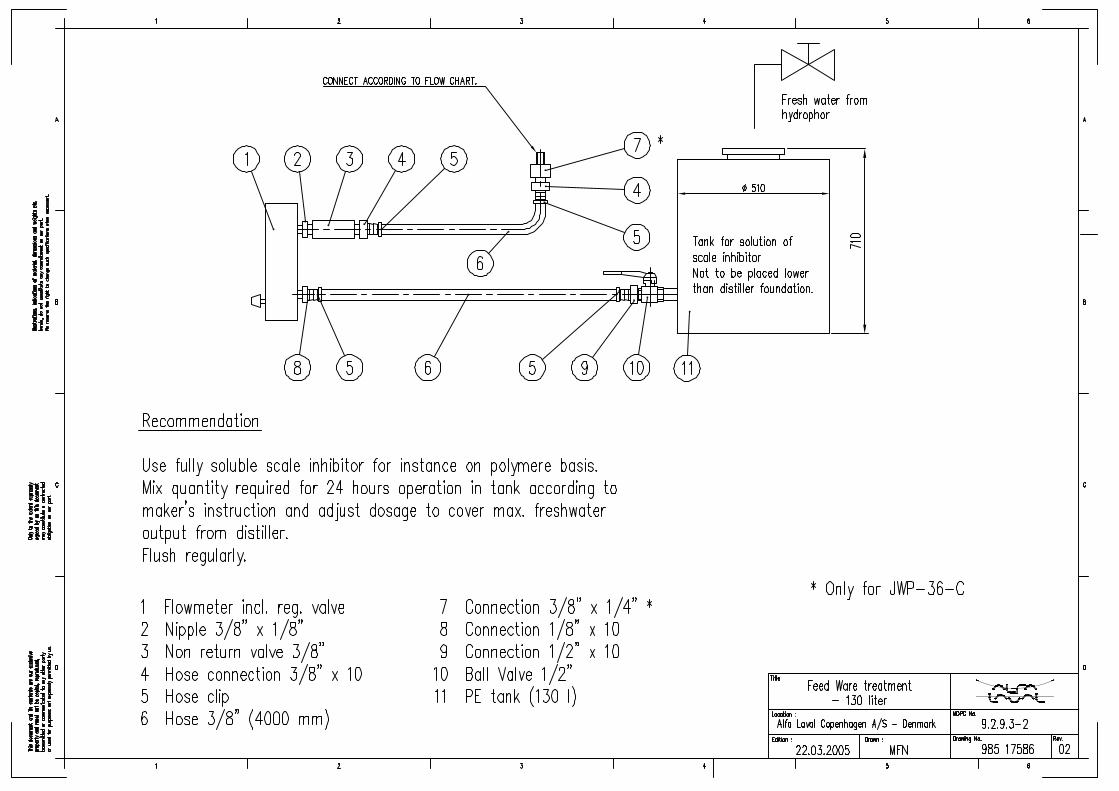
����� 6FDOH�,QKLELWRU�'RVDJH�(TXLSPHQW�IRU�)HHG�:DWHU
Please refer to drawing, see “FWG Order Specification”.
• When adding chemicals mix thoroughly to ensure a homogenous blend of chemicals and water.
Use a fully soluble scale inhibitor, e.g. on polymer basis. The following products can be recommended:
NALFLEET Evaporator treatment 9-913
AMEROYAL EVAPORATOR TREATMENT
HEXAMETHAPHOSPHATE
1. Mix the required quantity for 24 hours operation in the tank according to mak-er’s instructions.
2. Adjust flowmeter to cover the maximum freshwater output from the distiller.
3. Flush the dosage system regularly.
&$87,21
If the distiller is operated at boiling temperatures above 45°C without chem-icals, frequent cleaning of the evaporator will be necessary.
We recommend that you do not operate the freshwater distiller without rec-ommended chemical dosage at boiling temperatures above 45°C. Even at lower temperatures it can be recommended.
�� Cdgnpe00.fm

&KHPLFDO�'RVLQJ�RI�6FDOH�&RQWURO�&KHPLFDOV
����� 6DIHW\�3UHFDXWLRQV�ZLWK�WKH�XVH�RI�&KHPLFDOV
:$51,1*
1 USE eye protection and gloves. Avoid direct skin contact, eye contact or contact with clothes.
2 CLEAN empty containers before disposal.
3 If chemicals are spilled on clothes, rinse with water and dispose off clothes.
4 If chemicals are spilled on the floor, rinse with water and suck remain-ing chemicals off with sand. Clean the spot immediately afterwards.
5 Scale inhibitor is hazardous, if consumed in a concentrated solution. If consumed by mistake.,00(',$7(/<�6((.�0(',&$/�$77(17,21��
6 If eyes get in contact with the chemicals, rinse for at least 20 minutes.,00(',$7(/<�6((.�0(',&$/�$77(17,21�
Cdgnpe00.fm ��

&KHPLFDO�'RVLQJ�RI�6FDOH�&RQWURO�&KHPLFDOV
�� Cdgnpe00.fm

7URXEOH�6KRRWLQJ
����� 7HVW�6KHHW
Before taking any action, please fill in a test sheet to find possible causes of malfunc-tions.
Test sheets can be found in the back of this binder.
����� 7URXEOH�6KRRWLQJ�7DEOH
3UREOHP &DXVH $FWLRQ
Drop in production. Partially blocked feed water orifice and/or sludge deposits on hot water side.
Dismantle evaporator section, and clean evaporator and ori-fice.
Sludge on the heat exchanger plates on the sea water side.
Dismantle condenser section, and clean.
Inlet channel in evaporator/ condenser plate stack blocked, e.g. with rust scales, gasket fragments etc.
Dismantle evaporator/ con-denser section, and clean.
Too low ejector pump pres-sure.
See instructions for “Low Sea Cooling water/Ejector pump flow / pressure”, below.
Leakages Carry out a pressure test at max. 150 kPa (1.5 kp/cm²) (21.8 PSI).a
Foreign bodies in ejector noz-zles.
Inspect nozzles, and clean. Replace nozzles, if damaged.
Too high back pressure on ejector outlet side. Max 60 kPa (0.6 kp/cm²) (8.7 PSI).
Check overboard pipe and valves for blocking / function-ability.
Non-return valve in air extrac-tion pipe defect.
Replace non-return valve.
Hot water temperature too high.
Reduce to specified tempera-ture.
Defective water clock. Examine water clock. Let the produced water flow through water clock into a 10 l pail, and check production with a stop watch.
Trw26e03.fm ��
7URXEOH�6KRRWLQJ
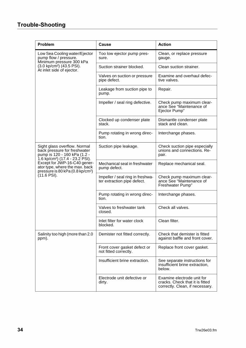
Low Sea Cooling water/Ejector pump flow / pressure.Minimum pressure 300 kPa (3.0 kp/cm²) (43.5 PSI).At inlet side of ejector.
Too low ejector pump pres-sure.
Clean, or replace pressure gauge.
Suction strainer blocked. Clean suction strainer.
Valves on suction or pressure pipe defect.
Examine and overhaul defec-tive valves.
Leakage from suction pipe to pump.
Repair.
Impeller / seal ring defective. Check pump maximum clear-ance See “Maintenance of Ejector Pump”
Clocked up condenser plate stack.
Dismantle condenser plate stack and clean.
Pump rotating in wrong direc-tion.
Interchange phases.
Sight glass overflow. Normal back pressure for freshwater pump is 120 - 160 kPa (1.2 - 1.6 kp/cm²) (17.4 - 23.2 PSI). Except for JWP-16-C40 gener-ator type, where the max. back pressure is 80 kPa (0.8 kp/cm²) (11.6 PSI).
Suction pipe leakage. Check suction pipe especially unions and connections. Re-pair.
Mechanical seal in freshwater pump defect.
Replace mechanical seal.
Impeller / seal ring in freshwa-ter extraction pipe defect.
Check pump maximum clear-ance See “Maintenance of Freshwater Pump”
Pump rotating in wrong direc-tion.
Interchange phases.
Valves to freshwater tank closed.
Check all valves.
Inlet filter for water clock blocked.
Clean filter.
Salinity too high (more than 2.0 ppm).
Demister not fitted correctly. Check that demister is fitted against baffle and front cover.
Front cover gasket defect or not fitted correctly.
Replace front cover gasket.
Insufficient brine extraction. See separate instructions for insufficient brine extraction, below.
Electrode unit defective or dirty.
Examine electrode unit for cracks. Check that it is fitted correctly. Clean, if necessary.
3UREOHP &DXVH $FWLRQ
�� Trw26e03.fm

7URXEOH�6KRRWLQJ
Leakage in condenser sec-tion.
Open distiller and pressure test condenser. Max. 600 kPa (6.0 kp/cm²) (87 PSI). If there is a defective plate, remove togeth-er with adjacent plate assem-ble plate stack according to new plate number with re-duced assembly measure-ments. Check plate gaskets and replace, if necessary.
Insufficient brine extraction - brine level in sight glass higher than 20 mm.
Ejector pump pressure too low.
See special instructions for “Low Sea Cooling water/Ejec-tor pump flow / pressure”, above.
Foreign bodies in ejector noz-zles.
Check nozzles, and clean. Re-place damaged nozzles.
Too high back pressure down-stream of ejector.
Examine overboard pipe and valves.
Wrong dimension of feedwa-ter orifice.
Examine orifice dimension - check technical specification.
Non-return valve in brine suc-tion pipe of ejector defect.
Examine valve and repair, or replace.
Frequent refill of freshwater expansion tank due to loss of hot water.
Leakage in evaporator sec-tion.
Open distiller and pressure test condenser. Max. 600 kPa (6.0 kp/cm²) (87 PSI). If there is a defective plate, re-move together with adjacent plates assemble plate stack according to new plate number with reduced assembly mea-surements. Check plate gas-kets and replace, if necessary.
Abnormal amperage con-sumption of ejector pump mo-tor.
Ejector nozzles defective. Replace nozzles.
Wrong dimension of feedwa-ter inlet orifice.
Check dimensions on spare parts list, See List of spare part drawings”, and replace if nec-essary.
Bearings in motor defective. Examine with stetoscope, and replace bearings, if defective.
Contactor defective. Examine and replace contactor set, if defective.
Breaking of phases. Max. 5% difference in amper-age between phases.
3UREOHP &DXVH $FWLRQ
Trw26e03.fm ��

7URXEOH�6KRRWLQJ
�� Trw26e03.fm

0DLQWHQDQFH�RI�)UHVKZDWHU�3XPS
����� 0DLQWHQDQFH�RI�)UHVKZDWHU�3XPS�7\SHV�399)���������������
The following instructions must be carefully observed whenever it becomes neces-sary to overhaul or repair the freshwater pump.
Please refer to drawing for item references in the text.
����� 2YHUKDXO�RI�WKH�3XPS
1. Remove the QXWV��� on the SXPS�FDVLQJ���
2. Lift motor with SXPS�FRYHU�� and LPSHOOHU�� clear of SXPS�FDVLQJ��.
3. Unscrew FRXQWHUVXQN�VFUHZ��� (right hand thread).
4. Remove impeller. Normally, it can be removed without using dismantling tools.
5. Remove NH\����
6. Remove the PHFKDQLFDO�VKDIW�VHDO����
7. Inspect the ceramic ring, the carbon ring and the spring.
8. Replace mechanical shaft seal, if necessary. It is recommended to grease the shaft and seat for the ceramic ring with glycerine in order to make it easier to assemble the mechanical shaft seal. Please also observe separate instruc-tions for mechanical shaft seal delivered together with the seal.
Mapvfe00.fm ��

0DLQWHQDQFH�RI�)UHVKZDWHU�3XPS
9. Fit carbon ring, spring and spring holder on pump shaft.
10. Inspect impeller and the drilled sealing water channel for clogging, and clean.
��� 5HPHPEHU�WR�UHSODFH�JDVNHW���
12. Reassemble in reverse order.
����� &OHDUDQFH
In connection with the inspection be sure to measure the LPSHOOHU�DQG�ZHDU�ULQJ����in order to secure that the clearance is no more than 0.5 mm on the diameter.
����� 'LVPDQWOLQJ�3XPS�6KDIW
1. Dismantle the pump as described above.
2. Unscrew SRLQWHG�VFUHZV����
3. Carefully insert two screw drivers behind the pump shaft, and loosen it.
,I�WKH�SXPS�VKDIW�GRHV�QRW�FRPH�ORRVH��XVH�WKH�VSHFLDO�GLVPDQWOLQJ�WRROV�VKRZQ�EHORZ�
7KH�WRRO�LV�QRW�$OID�/DYDO�'HVDOW�VXSSO\�
&$87,21
The SXPS�VKDIW��� must only be dismantled, if pump shaft or electric mo-tor bearing has to be replaced.
In this case carefully observe “Dismantling pump shaft”.
�� Mapvfe00.fm
0DLQWHQDQFH�RI�)UHVKZDWHU�3XPS
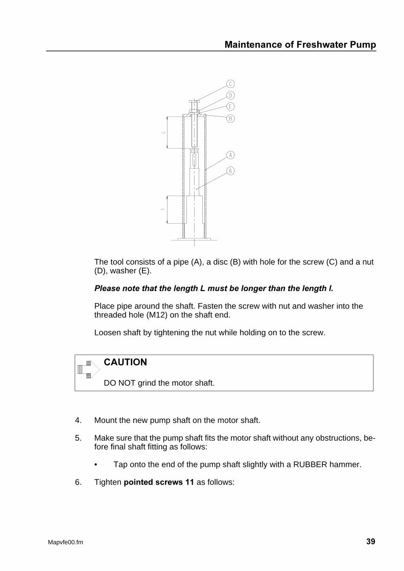
The tool consists of a pipe (A), a disc (B) with hole for the screw (C) and a nut (D), washer (E).
3OHDVH�QRWH�WKDW�WKH�OHQJWK�/�PXVW�EH�ORQJHU�WKDQ�WKH�OHQJWK�O�
Place pipe around the shaft. Fasten the screw with nut and washer into the threaded hole (M12) on the shaft end.
Loosen shaft by tightening the nut while holding on to the screw.
4. Mount the new pump shaft on the motor shaft.
5. Make sure that the pump shaft fits the motor shaft without any obstructions, be-fore final shaft fitting as follows:
• Tap onto the end of the pump shaft slightly with a RUBBER hammer.
6. Tighten SRLQWHG�VFUHZV��� as follows:
&$87,21
DO NOT grind the motor shaft.
Mapvfe00.fm ��

0DLQWHQDQFH�RI�)UHVKZDWHU�3XPS
7. Check the wobble of the pump shaft with a dial indicator.
8. Assemble the pump as described above.
127(
The torque should be 5 Nm (0.5 kpm) and the maximum wobble 60�µ�m.
�� Mapvfe00.fm

0DLQWHQDQFH�RI�(MHFWRU�3XPS
����� 0DLQWHQDQFH�RI�(MHFWRU�3XPS
�,I�VXSSOLHG�IURP�$OID�/DYDO�
The following instructions must be carefully observed whenever it becomes neces-sary to overhaul or repair the above mentioned pump. Please refer to drawing for item references in the text.
����� 2YHUKDXO�RI�WKH�3XPS
1. Remove the VHW�VFUHZV��� in SXPS�FRYHU���
0RWRU�ZLWK�PRWRU�EUDFNHW����SXPS�FRYHU����DQG�LPSHOOHU���FDQ�QRZ�EH�OLIWHG�FOHDU�RI�WKH�SXPS�FDVLQJ���
2. Unscrew the VFUHZ��� (right-hand thread).
3. Remove impeller.
Macnle00.fm ��

0DLQWHQDQFH�RI�(MHFWRU�3XPS
4. Remove the key 26 and the mechanical seal 8 (including spring holder, spring and carbon ring).
5. Inspect the ceramic ring, the carbon ring and the spring. Replace, if necessary
,I�PHFKDQLFDO�VHDO�KDV�WR�EH�UHSODFHG��SURFHHG�DV�IROORZV�
� 8QVFUHZ�VHW�VFUHZ����WR�UHPRYH�SXPS�FRYHU���IURP�PRWRU�EUDFNHW���LQ�RUGHU�WR�JDLQ�DFFHVV�WR�FHUDPLF�ULQJ�
,Q�RUGHU�WR�PDNH�LW�HDVLHU�WR�DVVHPEOH�WKH�PHFKDQLFDO�VHDO��WKH�VKDIW�DQG�ULQJ�VHDW�PD\�EH�JUHDVHG�ZLWK�JO\FHULQH��3OHDVH�DOVR�UHIHU�WR�VHSDUDWH�LQVWUXFWLRQV�IRU�PHFKDQLFDO�VHDO�GHOLYHUHG�WRJHWKHU�ZLWK�WKH�VHDO�
� $IWHU�ILWWLQJ�WKH�FHUDPLF�ULQJ��ILW�SXPS�FRYHU���WR�PRWRU�EUDFNHW���
� )LW�FDUERQ�ULQJ��VSULQJ�DQG�VSULQJ�KROGHU�
6. Clean drilled cooling water channel in SXPS�FRYHU���
7. Inspect impeller and threaded holes for clogging.
8. 5HPHPEHU�WR�FKDQJH�WKH�2�ULQJ���
9. Reassemble in reverse order.
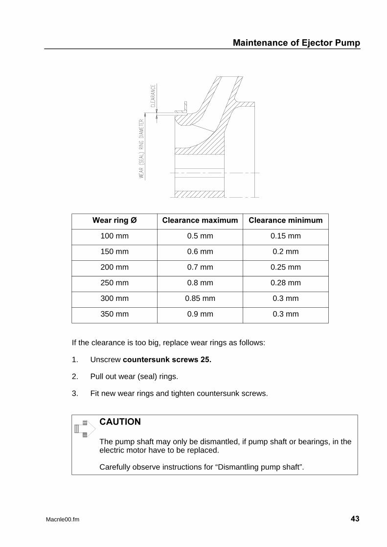
����� &OHDUDQFH
In connection with the inspection, the LPSHOOHU���and ZHDU�ULQJV��� are measured in order to secure that the clearance is not larger than stated in the diagram below.
127(
Normally, the impeller can be removed without using dismantling tools.
If not, you can fit dismantling screws into the two threaded holes in the im-peller.
�� Macnle00.fm
0DLQWHQDQFH�RI�(MHFWRU�3XPS
If the clearance is too big, replace wear rings as follows:
1. Unscrew FRXQWHUVXQN�VFUHZV����
2. Pull out wear (seal) rings.
3. Fit new wear rings and tighten countersunk screws.
:HDU�ULQJ�� &OHDUDQFH�PD[LPXP &OHDUDQFH�PLQLPXP
100 mm 0.5 mm 0.15 mm
150 mm 0.6 mm 0.2 mm
200 mm 0.7 mm 0.25 mm
250 mm 0.8 mm 0.28 mm
300 mm 0.85 mm 0.3 mm
350 mm 0.9 mm 0.3 mm
&$87,21
The pump shaft may only be dismantled, if pump shaft or bearings, in the electric motor have to be replaced.
Carefully observe instructions for “Dismantling pump shaft”.
Macnle00.fm ��

0DLQWHQDQFH�RI�(MHFWRU�3XPS
����� 'LVPDQWOLQJ�3XPS�6KDIW
If the�VKDIW�� has to be dismantled due to a defect or if electric motor bearing has to be replaced, proceed as follows:
1. Unscrew SRLQWHG�VFUHZV����
2. Remove VKDIW��. Normally this can be done without using dismantling tools.
3. Fit VKDIW���
4. In order to make sure that the coupling is fitted correctly, tap slightly at the shaft end with a RUBBER hammer.
5. Tighten�SRLQWHG�VFUHZV��� with a torque of 35 Nm (3.5 kpm).
&$87,21
DO NOT grind the motor shaft.
�� Macnle00.fm

6DOLQRPHWHU
����� 6DOLQRPHWHU�7\SH�'6���
����� 7HFKQLFDO�6SHFLILFDWLRQ
����� ,QVWDOODWLRQ��IRU�'6����
1. Open front cover.
2. Select correct voltage select according to the main supply voltage 115 V or 230 VAC.
3. Screw salinometer on to bulkhead with six nuts.
4. Connect necessary cables to the terminals.
5. Close front cover.
6. Test salinometer function (see instructions for use).
)XQFWLRQ Measuring (Dot Bar) and supervising salinity of freshwater produced by seawater desalination.
6XSSO\�YROWDJH 90-120 V or 200-240 V AC.
)UHTXHQF\ 50/60 Hz
3RZHU�FRQVXPSWLRQ Salinometer 10 VA.
5HOD\�FRQWDFWV Max. load 100 VA.
6DOLQLW\�GLVSOD\ 0,5 - 20 ppm (Dot Bar).
7HPSHUDWXUH�FRUUHFWLRQ Automatic in the range 5 - 85°C.
$ODUP�OHYHO Can be set to any value between 0,5 - 20 ppm.
7HVW Can be checked by test switch, 10 ppm.
2XWSXW 4-20 mA Current Loop.
0D[��DPELHQW�WHPSHUD�WXUH
55°C.
3URWHFWLRQ�GHJUHH IP 54.
Salise00.fm ��
6DOLQRPHWHU
����� ,QVWUXFWLRQV�IRU�XVH
1. Switch on mains.
2. Switch on sec. alarm.
Green pilot LED should light up. Dot. Bar displays the measured salinity.
����� 7HVWLQJ�WKH�,QVWUXPHQW
Push TEST switch on.
7KH�'RW�%DU�VKRXOG�UHDG����SSP�
,I�WKH�DODUP�OHYHO�LV�OHVV�WKDQ����SSP��WKH�VDOLQRPHWHU�ZLOO�JLYH�DQ�DODUP�
����� $GMXVWPHQW�RI�$ODUP�/HYHO
1. Switch “MAINS” on.
2. Push sec. alarm off.
3. Adjust Alarm Set to desired alarm level by using the switches.
4. Switch “Sec. Alarm” on.
The salinometer is now ready for use.
If the salinity exceeds the alarm level,
• The two red alarm LEDS flash.
• Solenoid valve is activated.
• Buzzer (if fitted) and external alarm system is activated.
Cancel buzzer and external alarm system by switching “Sec. Alarm” off. Solenoid valve is not affected.
Switch “Sec. Alarm” on as soon as the salinity is normal again; i.e. when the two red
:$51,1*
The salinometer must be tested at least once a month, and the electrode unit must be cleaned.
�� Salise00.fm
6DOLQRPHWHU
LEDS are off.
����� 0DLQWHQDQFH
&$87,21
Remove electrode unit and inspect/clean after every 1000 hours of opera-tion. Use a clean and dry rag. Avoid touching the electrodes with the fin-gers.
Salise00.fm ��

6DOLQRPHWHU
�� Salise00.fm

Spmare01.fm ��
6SDUH�3DUWV
����� 2UGHULQJ�6SDUH�3DUWV
When ordering spare parts please always state:
1. Serial number.
2. Capacity.
3. Designation.
4. Spare parts drawing number.
5. Position number.
6. Article number.
In order to identify article numbers, please refer to FWG Order Specification and oth-er drawings.
When ordering parts for pumps proceed as follows:
1. Find article number in the list of drawings.
2. Check spare part drawing and item list with corresponding article number to identify the item to be ordered.
����� $OID�/DYDO�6HUYLFH
The $OID�/DYDO�group is represented in all major ports of the world.
DO NOT hesitate to contact your $OID�/DYDO representative if you have any ques-tions, problems or require spare parts.

6SDUH�3DUWV
�� Spmare01.fm

,QGH[
$
Adjustment of alarm level . . . . . . . . . . . . . . . . . . . . . . . . . . . . . . . . . . . . . . . . . . page 46Adjustment of Jacket Water Flow . . . . . . . . . . . . . . . . . . . . . . . . . . . . . . . . . . . . page 12Adjustment of sea cooling water . . . . . . . . . . . . . . . . . . . . . . . . . . . . . . . . . . . . . page 13Adjustment of the freshwater production . . . . . . . . . . . . . . . . . . . . . . . . . . . . . . . page 16Alfa Laval service . . . . . . . . . . . . . . . . . . . . . . . . . . . . . . . . . . . . . . . . . . . . . . . . . page 49Alternative Steam . . . . . . . . . . . . . . . . . . . . . . . . . . . . . . . . . . . . . . . . . . . . . . . . page 9
%
Before starting up the plant with steam injection equipment . . . . . . . . . . . . . . . . page 14
&
Changing from steam injection heating to jacket cooling water . . . . . . . . . . . . . . page 17Chemical dosage . . . . . . . . . . . . . . . . . . . . . . . . . . . . . . . . . . . . . . . . . . . . . . . . . page 29Cleaning . . . . . . . . . . . . . . . . . . . . . . . . . . . . . . . . . . . . . . . . . . . . . . . . . . . . . . . . page 24Clearance . . . . . . . . . . . . . . . . . . . . . . . . . . . . . . . . . . . . . . . . . . . . . . . . . . . . . . page 42Condensation . . . . . . . . . . . . . . . . . . . . . . . . . . . . . . . . . . . . . . . . . . . . . . . . . . . . page 16
'
Dismantling pump shaft . . . . . . . . . . . . . . . . . . . . . . . . . . . . . . . . . . . . . . . . . . . . page 44
(
Ejector Pump . . . . . . . . . . . . . . . . . . . . . . . . . . . . . . . . . . . . . . . . . . . . . . . . . . . . page 41Evaporation . . . . . . . . . . . . . . . . . . . . . . . . . . . . . . . . . . . . . . . . . . . . . . . . . . . . . page 15
)
Feed water ratio . . . . . . . . . . . . . . . . . . . . . . . . . . . . . . . . . . . . . . . . . . . . . . . . . . page 29Fitting new gaskets . . . . . . . . . . . . . . . . . . . . . . . . . . . . . . . . . . . . . . . . . . . . . . . page 24Freshwater Pump Types PVVF 1525-1532-2040 . . . . . . . . . . . . . . . . . . . . . . . . page 37Freshwater Quality . . . . . . . . . . . . . . . . . . . . . . . . . . . . . . . . . . . . . . . . . . . . . . . . page 8
,
Installation (for DS-20) . . . . . . . . . . . . . . . . . . . . . . . . . . . . . . . . . . . . . . . . . . . . . page 45Instructions for use . . . . . . . . . . . . . . . . . . . . . . . . . . . . . . . . . . . . . . . . . . . . . . . page 46
/
Long term standstill . . . . . . . . . . . . . . . . . . . . . . . . . . . . . . . . . . . . . . . . . . . . . . . page 18
O36A2E05IX.fm ��
,QGH[
0
Main Components . . . . . . . . . . . . . . . . . . . . . . . . . . . . . . . . . . . . . . . . . . . . . . . . page 8Maintenance . . . . . . . . . . . . . . . . . . . . . . . . . . . . . . . . . . . . . . . . . . . . . . . . . . . . page 47Maintenance of condenser section . . . . . . . . . . . . . . . . . . . . . . . . . . . . . . . . . . . page 22Maintenance of ejector pump . . . . . . . . . . . . . . . . . . . . . . . . . . . . . . . . . . . . . . . page 41Maintenance of evaporator section . . . . . . . . . . . . . . . . . . . . . . . . . . . . . . . . . . . page 21Maintenance of Freshwater pump . . . . . . . . . . . . . . . . . . . . . . . . . . . . . . . . . . . page 37Maintenance of freshwater pump types PVVF 1525-1532-2040 . . . . . . . . . . . . page 37Maintenance of separator vessel . . . . . . . . . . . . . . . . . . . . . . . . . . . . . . . . . . . . page 20
2
Operating Hours . . . . . . . . . . . . . . . . . . . . . . . . . . . . . . . . . . . . . . . . . . . . . . . . . page 19Ordering spare parts . . . . . . . . . . . . . . . . . . . . . . . . . . . . . . . . . . . . . . . . . . . . . . page 49Overhaul intervals . . . . . . . . . . . . . . . . . . . . . . . . . . . . . . . . . . . . . . . . . . . . . . . . page 19Overhaul of the pump . . . . . . . . . . . . . . . . . . . . . . . . . . . . . . . . . . . . . . . . . . . . . page 41
3
Perform regular maintenance duties . . . . . . . . . . . . . . . . . . . . . . . . . . . . . . . . . . page 19Preparation of new gaskets . . . . . . . . . . . . . . . . . . . . . . . . . . . . . . . . . . . . . . . . page 24Pressure testing separator . . . . . . . . . . . . . . . . . . . . . . . . . . . . . . . . . . . . . . . . . page 27Prevention of scaling . . . . . . . . . . . . . . . . . . . . . . . . . . . . . . . . . . . . . . . . . . . . . page 29
5
Removal of old gaskets . . . . . . . . . . . . . . . . . . . . . . . . . . . . . . . . . . . . . . . . . . . page 23Renewal of plate heat exchanger gaskets . . . . . . . . . . . . . . . . . . . . . . . . . . . . . page 23
6
Safety instructions and warnings . . . . . . . . . . . . . . . . . . . . . . . . . . . . . . . . . . . . page 5Safety precautions with the use of chemicals . . . . . . . . . . . . . . . . . . . . . . . . . . . page 31Salinometer type DS-20 . . . . . . . . . . . . . . . . . . . . . . . . . . . . . . . . . . . . . . . . . . . page 45Scale inhibitor dosage equipment for feed water . . . . . . . . . . . . . . . . . . . . . . . . page 30Spare Parts . . . . . . . . . . . . . . . . . . . . . . . . . . . . . . . . . . . . . . . . . . . . . . . . . . . . . page 49Starting and Stopping Procedure . . . . . . . . . . . . . . . . . . . . . . . . . . . . . . . . . . . . page 11Starting up the plant with steam injection equipment (AS) . . . . . . . . . . . . . . . . . page 15Starting-up the Plant with Jacket Cooling Water Heating . . . . . . . . . . . . . . . . . . page 11Stopping the plant . . . . . . . . . . . . . . . . . . . . . . . . . . . . . . . . . . . . . . . . . . . . . . . . page 13Stopping the plant working with steam injection heating . . . . . . . . . . . . . . . . . . page 16
7
Technical specification . . . . . . . . . . . . . . . . . . . . . . . . . . . . . . . . . . . . . . . . . . . . page 45Telefax . . . . . . . . . . . . . . . . . . . . . . . . . . . . . . . . . . . . . . . . . . . . . . . . . . . . . . . . page 5Telephone . . . . . . . . . . . . . . . . . . . . . . . . . . . . . . . . . . . . . . . . . . . . . . . . . . . . . . page 5Test sheet . . . . . . . . . . . . . . . . . . . . . . . . . . . . . . . . . . . . . . . . . . . . . . . . . . . . . . page 33Testing the instrument . . . . . . . . . . . . . . . . . . . . . . . . . . . . . . . . . . . . . . . . . . . . page 46Trouble shooting table . . . . . . . . . . . . . . . . . . . . . . . . . . . . . . . . . . . . . . . . . . . . page 33
�� O36A2E05IX.fm
,QGH[
:
Warning . . . . . . . . . . . . . . . . . . . . . . . . . . . . . . . . . . . . . . . . . . . . . . . . . . . . . . . . page 5Why you need to perform regular maintenance duties . . . . . . . . . . . . . . . . . . . . page 19Working Principle . . . . . . . . . . . . . . . . . . . . . . . . . . . . . . . . . . . . . . . . . . . . . . . . page 7
O36A2E05IX.fm ��
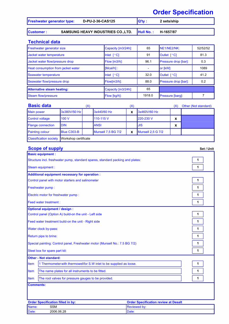
Order SpecificationFreshwater generator type: D-PU-2-36-CAS125 Q'ty : 2 sets/ship
Customer : SAMSUNG HEAVY INDUSTRIES CO.,LTD. Hull No. : H-1657/87
Technical dataFreshwater generator size Capacity [m3/24h]: 65 NE1/NE2/NK: 52/52/52
Jacket water temperature Inlet [ °C] 91 Outlet [ °C] 81.3
Jacket water flow/pressure drop Flow [m3/h]: 96.1 Pressure drop [bar]: 0.3
Heat consumption from jacket water [Mcal/h] : - or [kW]: 1089
Seawater temperature Inlet [ °C] 32.0 Outlet [ °C] 41.2
Seawater flow/pressure drop Flow[m3/h]: 88.0 Pressure drop [bar]: 0.2
Alternative steam heating: Capacity [m3/24h]:
Steam flow/pressure Flow [kg/h]: Pressure [barg]:
Basic data (X) (X) (X) Other (Not standard)
Main power 3x380V/50 Hz 3x440/60 Hz x 3x460V/60 Hz
Control voltage 100 V 110-115 V 220-230 V xFlange connection DIN ANSI JIS xPainting colour Blue C303-B Munsell 7,5 BG 7/2 x Munsell 2,5 G 7/2
Classification society Workshop certificate
Scope of supply Set / UnitBasic equipment :
Structure incl. freshwater pump, standard spares, standard packing and plates: 1
Steam equipment : 1
Additional equipment necessary for operation :
Control panel with motor starters and salinometer 1
Freshwater pump : 1
Electric motor for freshwater pump : 1
Feed water treatment : 1
Optional equipment / design :Control panel (Option A) build-on the unit - Left side 1
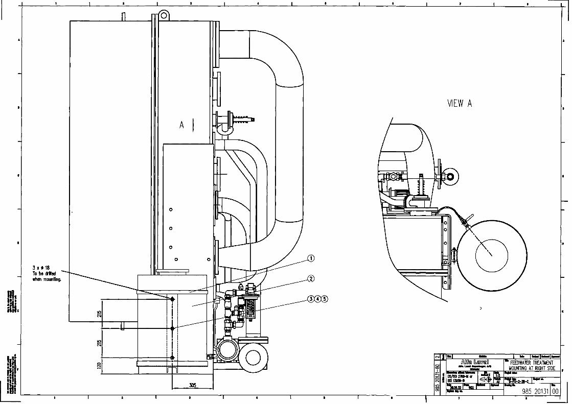
Feed water treatment build-on the unit - Right side 1
Water clock by-pass: 1
Return pipe to brine: 1
Special painting: Control panel, Freshwater motor (Munsell No.: 7.5 BG 7/2) 1
Steel box for spare part kit: 1
Other - Not standard:
Item 1 Thermometer with thermowell for S.W inlet to be supplied as loose. 1
Item The name plates for all instruments to be fitted. 1
Item The root valves for pressure gauges to be provided. 1
Comments:
Order Specification filled in by: Order Specification review at DesaltName: SSM Reviewed by:Date: 2006.06.28 Date:
1918.0 7
65

Marine & Diesel Product Catalogue.
Article no 985 20461-R01 Page 1 of 1 Illustrations, indications of material, dimensions and weights etc. herein, do not constitute any commitment on our part. We reserve the right to change such specification when necessary.
9.2.4.2-4 Technical data, Pump and Motor for D-PU-2-36-C(AS)125
9.2.4.2-4 Technical data, Pump and Motor for D-PU-2-36-C(AS)125
No. of plates NE/NK 50/50/50-58/58/58 Pump function *Freshwater Ejector
Pump type PVVF-2040 CNL 80-80/200 Motor type 71 B 160 L Nom. Flow x pressure m3/h x mwc 2.1 x 28 88 x 38 Impeller size 50 Hz: mm ø149 ø192 Impeller size 60 Hz: mm ø128 ø168 Rotating speed 50 Hz: RPM 2820 2915 Rotating speed 60 Hz: RPM 3360 3515
3 x 380 V 50 Hz Rated output power kW 0,55 18,6 Consumed power kW 0,67 18,2 Current (full load) A 1,4 33,5 Current (start) A 7 211
3 x 440 V 60 Hz Rated output power kW 0,75 21,4 Consumed power kW 0,75 18,2 Current (full load) A 1,6 33,5 Current (start) A 7 211
3 x 460 V 60 Hz Rated output power kW 0,75 21,4 Consumed power kW 0,75 18,2 Current (full load) A 1,5 32 Current (start) A 7 211
* Unit are equipped with two freshwater pumps.
KRSESSM
KRSESSM
KRSESSM
KRSESSM
KRSESSM
KRSESSM
KRSESSM
KRSESSM
KRSESSM

Marine & Diesel Product Catalogue.
Article no 985 20424-R01 Page 1 of 2 Illustrations, indications of material, dimensions and weights etc. herein, do not constitute any commitment on our part. We reserve the right to change such specification when necessary.
9.2.4.1 General description, D-PU-2-36-C(AS)100/125
Application
Conversion of seawater into freshwater by vacuum distillation, for drinking, process water, and domestic Use on ships and rigs, and in small power stations. Max. salinity 2 ppm.
Capacity
The D-PU-2-36-C(AS)100/125 covers capacity range from 20 to 75 m3/24h, depending on the heating medium and seawater temperature. The capacities shown below are at a seawater temperature of 32°C.
Working principle
The seawater to be distilled evaporates at a temperature of about 70°C as it passes between the hot Plates in the heat exchanger. The boiling temperature corresponds to a vacuum of about 70%, which is maintained in stage one by a brine/air ejector. The steam generated passes through a demister where any drops of seawater entrained in the steam are removed and allowed to the bottom of the distiller chamber. The steam is then led through a connecting pipe to the lower heat exchanger in stage two where it is condensed into fresh water. During condensation, the heat of evaporation is transferred to the feed water (brine) obtained from stage one. The brine boils at a temperature of about 45°C, corresponding to a vacuum of about 90%, which is maintained in stage two by the combined brine/air ejector. As in stage one, the generated steam passes through a demister to remove any entrained seawater, which is collected at the bottom of the distiller chamber of stage two. The steam then continues to the upper heat exchanger in stage two where it is condensed into fresh water. The heat transferred to seawater used for cooling the condenser is utilized by employing a part of the condenser outlet water as feed for stage one.

Marine & Diesel Product Catalogue.
Article no 985 20424-R01 Page 2 of 2 Illustrations, indications of material, dimensions and weights etc. herein, do not constitute any commitment on our part. We reserve the right to change such specification when necessary.
9.2.4.1 General description, D-PU-2-36-C(AS)100/125
Basic equipment
Titanium plate heat exchanger in evaporator and condenser. Stainless steel separator and stainless steel demister, front cover and pressure plates. Seawater pipes in CuNi. The freshwater generator is equipped for jacket water heating and with a combined condenser and ejector water system. Furthermore the freshwater generator is equipped with dump valve, water clock, automatic feed water regulator, combined brine/air ejector, instruments, freshwater pump with electric motor, internal piping and bed frame.
Options
Flanges: JIS
Power/control: 3 x 440 V 60 Hz 100/110/220 V
Additional equipment necessary for operation
- Control panel with motor starters and salinometer - Feed water treatment
Optional equipment/design
- Steam heating system type CAS and CS - Salinometer - Manual motor starters and salinometer - Remote start/stop - Water clock by-pass - Return pipe to brine sump - Electric panel build-on the unit - Steel box for spares kit - Freshwater treatment equipment

Marine & Diesel Product Catalogue.
Article no 985 20427-R01 Page 1 of 1 Illustrations, indications of material, dimensions and weights etc. herein, do not constitute any commitment on our part. We reserve the right to change such specification when necessary.
9.2.4.2-3 Technical data, D-PU-2-36-C(AS)125
Power consumption
Freshwater pump: 60 Hz 0,75 kW
Pressure
bar(g) Ibs/in2 Max. jacket water pressure: 4,0 58 Max. back pressure to freshwater tank 1,6 23 Max. seawater pressure to inlet condenser: 4,0 58 Min. seawater pressure to ejector: 3,0 43 Max. back pressure at ejector outlet: 0,6 8,7 Max. back pressure for safety valve on steam equipment: 1,0 14,5 Max. steam pressure for steam equipment: 7,0 101 Normal operation for steam equipment: 2 – 4,5 29-65 Back pressure to condensate well for steam equipment: 0,6 – 0,8 8,7 – 11,6
Temperature
Seawater temperature: 0 – 32°C Jacket water temperature: 55 – 95°C
Flow
Seawater flow: 88 m3/h Jacket water flow: 54 – 130 m3/h Materials
Separator: Stainless steel Front cover: Stainless steel Bed frame: Steel (hot dip galvanized) Pipe for brine discharge: SG-iron (hot dip galvanized) Evaporator/condenser plates: Titanium Demister: Stainless steel Pipe for seawater: CuNi 90/10 Pipe for freshwater: CuNi 90/10 Combined brine/air ejector housing: Red brass Combined brine/air ejector nozzle: Stainless steel Flange for evaporator/condenser: SG-iron (hot dip galvanized) Steam equipment type JWSP and SP Pipe: Steel (hot dip galvanized) Steam injector housing: SG-iron (painted) Steam injector nozzle: Stainless steel
Shipping data
Freshwater generator, complete with ejector pump, electrical panel, dosing unit and standard spares.
Weight: Net: 2650 kg, gross: 2800 kg Dimensions: l x w x h: 2700 x 1500 x 2400 mm Volume: 9,7 m3


KRSESSM
18

KRSESSM
Marine & Diesel Product Catalogue.
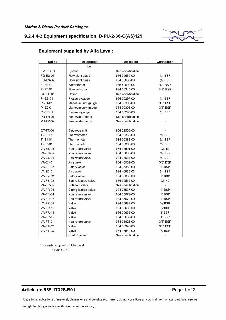
Article no 985 17326-R01 Page 1 of 2 Illustrations, indications of material, dimensions and weights etc. herein, do not constitute any commitment on our part. We reserve the right to change such specification when necessary.
9.2.4.4-2 Equipment specification, D-PU-2-36-C(AS)125
Equipment supplied by Alfa Laval:
Tag no Description Article no Connection
Unit: EW-ES-01 Ejector See specification - FG-ES-01 Flow sight glass 984 35686-00 ½” BSP FG-ES-02 Flow sight glass 984 35686-00 ½” BSP FI-FR-01 Water meter 985 42600-04 ¾ ” BSP FI-FT-01 Flow indicator 984 30345-00 3/8’’ BSP OC-FE-01 Orifice See specification - PI-ES-01 Pressure gauge 984 30297-00 ¼” BSP PI-E1-01 Mano/vacuum gauge 984 30308-00 3/8” BSP PI-E2-01 Mano/vacuum gauge 984 30308-00 3/8” BSP PI-FR-01 Pressure gauge 984 30298-00 ¼” BSP PU-FR-01 Freshwater pump See specification - PU-FR-02 Freshwater pump See specification - QT-FR-01 Electrode unit 984 22500-00 - TI-ES-01 Thermometer 984 30366-00 ½” BSP TI-E1-01 Thermometer 984 30366-00 ½” BSP TI-E2-01 Thermometer 984 30366-00 ½” BSP VA-ES-01 Non return valve 984 35501-00 DN 50 VA-ES-02 Non return valve 984 35686-00 ½” BSP VA-ES-03 Non return valve 984 35686-00 ½” BSP VA-E1-01 Air screw 984 40939-03 3/8” BSP VA-E1-02 Safety valve 984 35360-00 1” BSP VA-E2-01 Air screw 984 40939-03 ¼” BSP VA-E2-02 Safety valve 984 35360-00 1” BSP VA-FE-02 Spring loaded valve 984 35535-00 DN 40 VA-FR-02 Solenoid valve See specification - VA-FR-03 Spring loaded valve 984 35537-00 1“ BSP VA-FR-04 Non return valve 984 35672-00 1” BSP VA-FR-08 Non return valve 984 35672-00 1” BSP VA-FR-09 Valve 984 35683-00 ½’’BSP VA-FR-10 Valve 984 35683-00 ½’’BSP VA-FR-11 Valve 984 35639-00 1’’BSP VA-FR-12 Valve 984 35639-00 1’’BSP VA-FT-01 Non return valve 984 35623-00 3/8” BSP VA-FT-02 Valve 984 30345-00 3/8” BSP VA-FT-03 Valve 984 35542-00 ½’’BSP Control panel* See specification -
*Normally supplied by Alfa Laval ** Type CAS

Marine & Diesel Product Catalogue.
Article no 985 17326-R01 Page 2 of 2 Illustrations, indications of material, dimensions and weights etc. herein, do not constitute any commitment on our part. We reserve the right to change such specification when necessary.
9.2.4.4-2 Equipment specification, D-PU-2-36-C(AS)125
Steam arrangement**
IS-SS-01 Steam injector See specification -
PI-SS-01 Mano/vacuum gauge 984 30285-00 3/8’’ BSP
TI-SS-01 Thermometer 984 30366-00 ½” BSP TI-SS-02 Thermometer 984 30366-00 ½” BSP VA-SS-01 Butterfly valve 984 35634-00 DN 125 VA-SS-02 Safety valve See specification - VA-SS-03 Ball valve 984 35618-00 3/8” BSP VA-SS-04 Seated valve 985 56110-04 ¾’’ BSP VA-SS-05 Butterfly valve 984 35635-00 DN 150


Marine & Diesel Product Catalogue.
Article no 985 20435-R01 Page 1 of 2 Illustrations, indications of material, dimensions and weights etc. herein, do not constitute any commitment on our part. We reserve the right to change such specification when necessary.
9.2.6.1-4 Technical data, Control panel for Freshwater Generator
General
Control panel for single- and two-stage freshwater generators. Include start/stop of pumps and salinity supervision. The panel is internally connected, and needs only to be connected to main power and to the electrical components on the freshwater generator.
Standard Design
Standard design consists of a box with the following components built in: Main switch (locks panel if power is on) Push button for freshwater, ejector and ejector pump
- Start (green) - Stop (red)
Signal lamp for freshwater and ejector pump running (green)Signal lamp for source on (white) Thermal rely and contractor for:
- Freshwater pump(s) - Ejector pump
Operating transformer Salinometer Fuses Nameplate (inside panel) Painting: Munsell 7.5 BG 7/2
Electrical Design
Supply voltage: 3 x 440 V 60 Hz Control voltage: 220 V Permissible tolerances: Voltage: +10/-15% Frequency: + 2% Internal wire: Class 70°C External connections: Remote alarm, thermal overload freshwater pump – NO Remote alarm, thermal overload ejector pump – NO Remote start/stop freshwater pump
Marine & Diesel Product Catalogue.
Article no 985 20435-R01 Page 2 of 2 Illustrations, indications of material, dimensions and weights etc. herein, do not constitute any commitment on our part. We reserve the right to change such specification when necessary.
9.2.6.1-4 Technical data, Control panel for Freshwater Generator
Remote start/stop ejector pump Contact set, freshwater pump running - NC Contact set, freshwater pump running – NO Contact set, ejector pump running – NC Contact set, ejector pump running – NO External connections (salinometer): External meter Electrode unit External alarm contact – NC External alarm contact – NO Buzzer Solenoid valve – NC Solenoid valve – NO
Other Data
Protection degree: IP 44 Max. ambient temperature: 50°C Dimensions: 400 x 600 x 200 mm Weight: approx. 27 kg
Options (Supplied by Alfa Laval)
- Ammeter for ejector pump - Running hour meter for ejector pump - Mini circuit breaker to protect freshwater pump - Relay for thermal overload - NC


KRSESSM
KRSESSM
KRSESSM
KRSESSM
650

Equipment specificationFreshwater generator D-PU-36-CAS125
List of loose supply itemsNo. Drawing No. Article No. Set(s)/Unit Remark
1 Thermometer 984 20577 985 00080-99 1 S.W InL=100mm
DEPT DATE DRAWN CHECKED APPROVED DOCUMENT NO.
Market support 991102 SSK BCI YHM LOOSE.XLS
Description
KRSESSM
KRSESSM
*For S.W line inlet - 1 EA

KRSESSM
KRSESSM
KRSESSM
KRSESSM


![Alfacubic- Alfa Laval[1]](https://static.fdocument.pub/doc/165x107/577cd5841a28ab9e789afe44/alfacubic-alfa-laval1.jpg)