A AUDIO/VIDEO RECEPT AUDIO/VIDEO АУДИОВИДЕО …€¦ · rd-6506 a operating instructions...
46
RD-6506 AUDIO/VIDEO RECEIVER OPERATING INSTRUCTIONS INSTRUCCIONES DE FUNCIONAMIENTO RECEPTOR DE AUDIO/VIDEO RECEPTEUR AUDIO/VIDEO MODE D'EMPLOI АУДИО/ВИДЕО ПРИЕМНИК ИНСТРУКЦИЯ ПО ЭКСПЛУАТАЦИИ AUDIO/VIDEO RECEIVER BEDIENUNGSANLEITUNG 6505(G) cover_5lan_cover.qxp 2011-04-14 오전 9:43 페이지 1
Transcript of A AUDIO/VIDEO RECEPT AUDIO/VIDEO АУДИОВИДЕО …€¦ · rd-6506 a operating instructions...
RD-6506AUDIO/VIDEO RECEIVER
OPERATING INSTRUCTIONS
INSTRUCCIONES DE FUNCIONAMIENTO
RECEPTOR DE AUDIO/VIDEO
RECEPTEUR AUDIO/VIDEO
MODE D'EMPLOI
АУДИО/ВИДЕО ПРИЕМНИК
ИНСТРУКЦИЯ ПО ЭКСПЛУАТАЦИИ
AUDIO/VIDEO RECEIVER
BEDIENUNGSANLEITUNG
6505(G) cover_5lan_cover.qxp 2011-04-14 오전 9:43 페이지 1
ENGLISH
2
Introduction
: TO REDUCE THE RISK OF FIRE OR ELECTRIC SHOCK, DO NOT EXPOSE THIS APPLIANCE TO RAIN OR MOISTURE.
This symbol is intended to alert the user to the presence ofuninsulated "dangerous voltage" within the product'senclosure that may be of sufficient magnitude to constitutea risk of electric shock to persons.
This symbol is intended to alert the user to the presence ofimportant operating and maintenance (servicing)instructions in the literature accompanying the appliance.
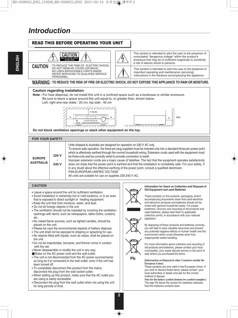
Caution regarding installationNote : For heat dispersal, do not install this unit in a confined space such as a bookcase or similar enclosure.
Be sure to leave a space around this unit equal to, or greater than, shown below. Left, right and rear sides : 20 cm, top side : 40 cm
: TO REDUCE THE RISK OF ELECTRIC SHOCK,DO NOT REMOVE COVER (OR BACK). NO USER-SERVICEABLE PARTS INSIDE.REFER SERVICING TO QUALIFIED SERVICEPERSONNEL.
CAUTION
WARNING
Do not block ventilation openings or stack other equipment on the top.
READ THIS BEFORE OPERATING YOUR UNIT
ON / STANDBY AUTO / MANUAL SURROUND STEREO VIDEO AUDIO
SOUND INPUT
AUDIO ASSIGNSPEAKER
ON / OFF
TONE CH.LEVEL SETUP ENTER / MEMO BANDPRESETTUNEPHONES
AUX 1 AUX 2
POWER
AUDIO / VIDEO RECEIVER RD-6505
ON OFF
RETURN MAIN MENU
MASTER VOLUME
CAUTION
FOR YOUR SAFETY
Units shipped to Australia are designed for operation on 230 V AC only.To ensure safe operation, the three-pin plug supplied must be inserted only into a standard three-pin power pointwhich is effectively earthed through the normal household wiring. Extension cords used with the equipment mustbe three-core and be correctly wired to provide connection to earth.Improper extension cords are a major cause of fatalities. The fact that the equipment operates satisfactorilydoes not imply that the power point is earthed and that the installation is completely safe. For your safety, ifin any doubt about the effective earthing of the power point, consult a qualified electrician.PAN-EUROPEAN UNIFIED VOLTAGEAll units are suitable for use on supplies 220-240 V AC.
EUROPEAUSTRALIA
220 V-
240 V
• Leave a space around the unit for sufficient ventilation.• Avoid installation in extremely hot or cold locations, or in an area
that is exposed to direct sunlight or heating equipment. • Keep the unit free from moisture, water, and dust.• Do not let foreign objects in the unit.• The ventilation should not be impeded by covering the ventilation
openings with items, such as newspapers, table-cloths, curtains,etc.
• No naked flame sources, such as lighted candles, should beplaced on the unit.
• Please be care the environmental aspects of battery disposal.• The unit shall not be exposed to dripping or splashing for use.• No objects filled with liquids, such as vases, shall be placed on
the unit.• Do not let insecticides, benzene, and thinner come in contact
with the set.• Never disassemble or modify the unit in any way.■Notes on the AC power cord and the wall outlet.• The unit is not disconnected from the AC power source(mains)
as long as it is connected to the wall outlet, even if the unit hasbeen turned off.
• To completely disconnect this product from the mains,disconnect the plug from the wall socket outlet.
• When setting up this product, make sure that the AC outlet youare using is easily accessible.
• Disconnect the plug from the wall outlet when not using the unitfor long periods of time.
Information for Users on Collection and Disposal ofOld Equipment and used Batteries
These symbols on the products, packaging, and/oraccompanying documents mean that used electricaland electronic products and batteries should not bemixed with general household waste. For propertreatment, recovery and recycling of old products andused batteries, please take them to applicablecollection points, in accordance with your nationallegislation.
By disposing of these products and batteries correctly,you will help to save valuable resources and preventany potential negative effects on human health and theenvironment which could otherwise arise frominappropriate waste handling.
For more information about collection and recycling ofold products and batteries, please contact your localmunicipality, your waste diposal service or the point ofsale where you purchased the items.
[Information on Disposal in other Countries outside the
European Union]
These symbols are only valid in the European Union. Ifyou wish to discard these items, please contact yourlocal authorities or dealer and ask for the correctmethod of diposal.Note for the battery symbol (bottom two symbol examples):
The sign Pb below the symbol for batteries indicatesthat this batteries contains lead.
RD-6506(G)_ENG_110330_RD-6506(G)_ENG 2011-04-14 오전 9:29 페이지 2
3
ENGLISH
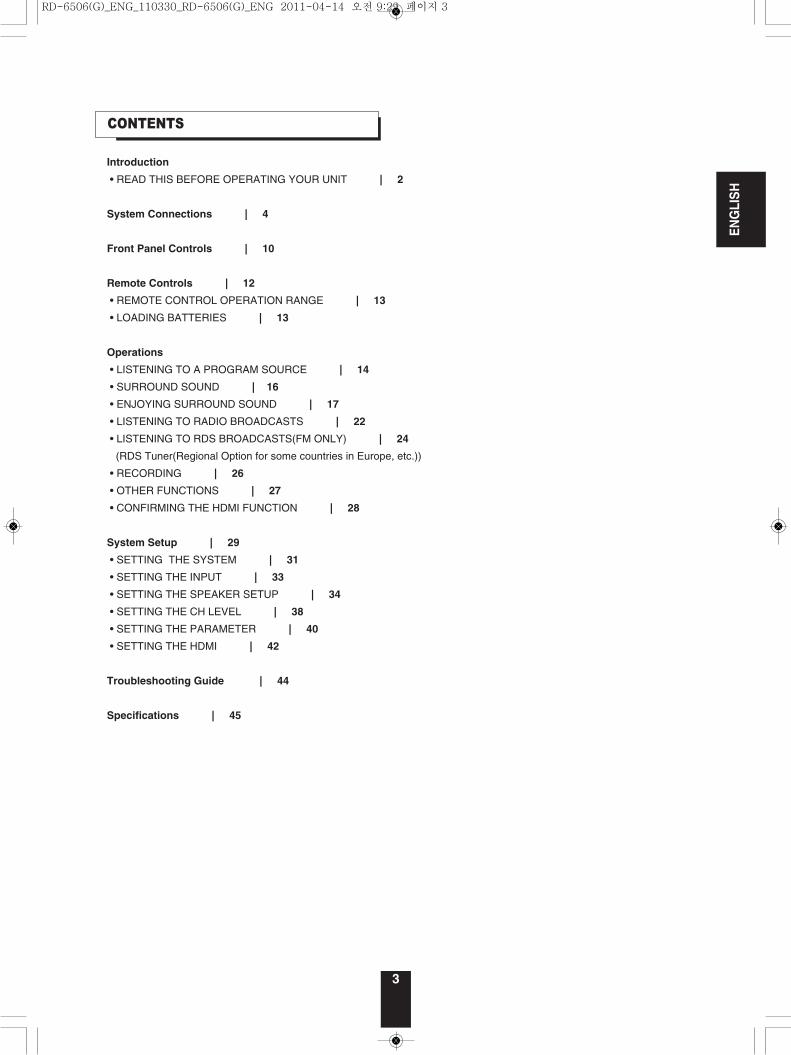
CONTENTS
Introduction
• READ THIS BEFORE OPERATING YOUR UNIT | 2
System Connections | 4
Front Panel Controls | 10
Remote Controls | 12
• REMOTE CONTROL OPERATION RANGE | 13
• LOADING BATTERIES | 13
Operations
• LISTENING TO A PROGRAM SOURCE | 14
• SURROUND SOUND | 16
• ENJOYING SURROUND SOUND | 17
• LISTENING TO RADIO BROADCASTS | 22
• LISTENING TO RDS BROADCASTS(FM ONLY) | 24
(RDS Tuner(Regional Option for some countries in Europe, etc.))
• RECORDING | 26
• OTHER FUNCTIONS | 27
• CONFIRMING THE HDMI FUNCTION | 28
System Setup | 29
• SETTING THE SYSTEM | 31
• SETTING THE INPUT | 33
• SETTING THE SPEAKER SETUP | 34
• SETTING THE CH LEVEL | 38
• SETTING THE PARAMETER | 40
• SETTING THE HDMI | 42
Troubleshooting Guide | 44
Specifications | 45
RD-6506(G)_ENG_110330_RD-6506(G)_ENG 2011-04-14 오전 9:29 페이지 3
ENGLISH
4
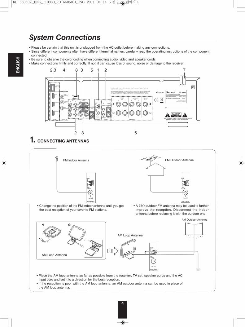
System Connections• Please be certain that this unit is unplugged from the AC outlet before making any connections.• Since different components often have different terminal names, carefully read the operating instructions of the component
connected.• Be sure to observe the color coding when connecting audio, video and speaker cords.• Make connections firmly and correctly. If not, it can cause loss of sound, noise or damage to the receiver.
SN.
SPEAKERS
R L R L
SURROUND(6 )
CENTER(6 )
FRONT(6 )
POWER SOURCEPOWER CONSUMPTION
RD-6506
230V 50Hz200W
DESIGNED IN USAASSEMBLED IN CHINA
N18041
HDMI
VIDEO 2
VIDEO 1
MONITOROUT
CD
DIGITAL IN
R LIN
VIDEO 2
IN OUT
MONITOROUT
VIDEO 1 VIDEO 1
VIDEOANTENNAAUDIO
FM 75
GND
AMLOOP
COAX 2(CD)
OPT(VIDEO 1)
AVIS : RISQUE DE CHOC ELECTRIQUE-NE PAS OUVRIR.WARNING : SHOCK HAZARD-DO NOT OPEN.
VID
EO
1V
IDE
O 2
CD
VID
EO
1TA
PE
TAP
E
R L
IN
OUT
Manufactured under license from Dolby Laboratories. Dolby, Pro Logic, and the double-D symbol are trademarks of Dolby Laboratories.
SUBWOOFEROUT
COAX 1(VIDEO 2) AUDIO/VIDEO RECEIVER
Manufactured under license under U.S. Patent #’s: 5,451,942 5,956,674 5,974,380 5,978,762 6,487,535 & other U.S. and worldwide patents issued & pending. DTS and the Symbol are registered trademarks & DTS Digital Surround and the DTS logos are trademarks of DTS, Inc. © DTS, Inc. All Rights Reserved.
842,3 3
2 3 6
5 1 2 7
1. CONNECTING ANTENNAS
ANTENNA
FM 75
GND
AMLOOP
ANTENNA
FM 75
GND
AMLOOP
• Change the position of the FM indoor antenna until you getthe best reception of your favorite FM stations.
ANTENNA
FM 75
GND
AMLOOP
• Place the AM loop antenna as far as possible from the receiver, TV set, speaker cords and the ACinput cord and set it to a direction for the best reception.
• If the reception is poor with the AM loop antenna, an AM outdoor antenna can be used in place ofthe AM loop antenna.
• A 75Ω outdoor FM antenna may be used to furtherimprove the reception. Disconnect the indoorantenna before replacing it with the outdoor one.
RD-6506(G)_ENG_110330_RD-6506(G)_ENG 2011-04-14 오전 9:29 페이지 4
5
ENGLISH
HDMI
VIDEO 2
VIDEO 1
MONITOROUT
VIDEO 2
IN OUT
MONITOROUT
VIDEO 1 VIDEO 1
VIDEO
AUDIO
VID
EO
1V
IDE
O 2
VID
EO
1
IN
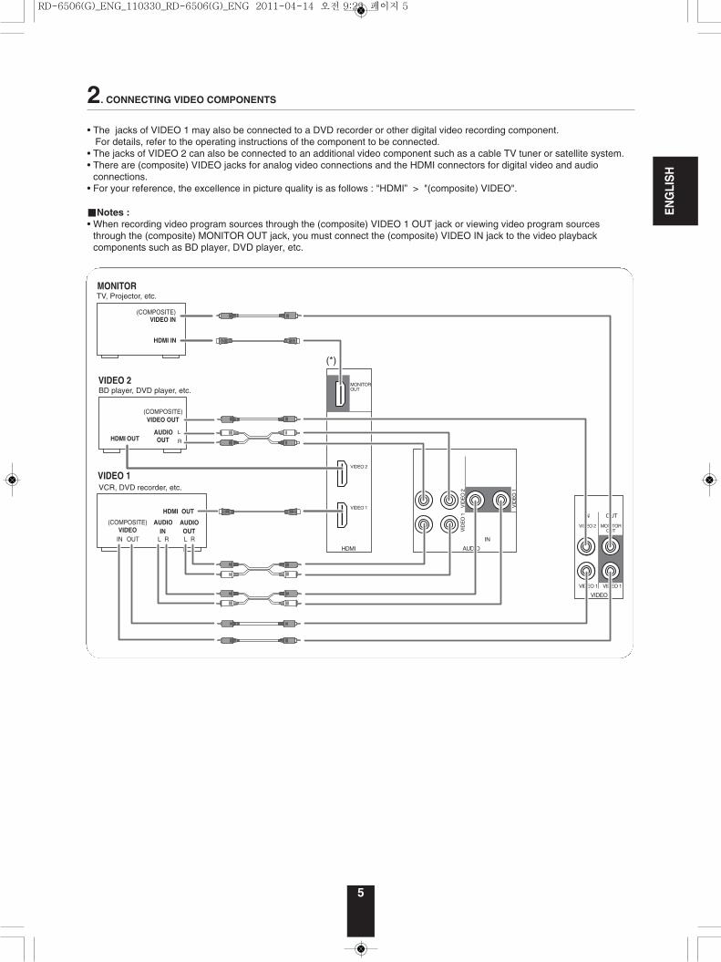
2. CONNECTING VIDEO COMPONENTS
• The jacks of VIDEO 1 may also be connected to a DVD recorder or other digital video recording component. For details, refer to the operating instructions of the component to be connected.
• The jacks of VIDEO 2 can also be connected to an additional video component such as a cable TV tuner or satellite system. • There are (composite) VIDEO jacks for analog video connections and the HDMI connectors for digital video and audio
connections.• For your reference, the excellence in picture quality is as follows : "HDMI” > "(composite) VIDEO".
■Notes :• When recording video program sources through the (composite) VIDEO 1 OUT jack or viewing video program sources
through the (composite) MONITOR OUT jack, you must connect the (composite) VIDEO IN jack to the video playbackcomponents such as BD player, DVD player, etc.
RD-6506(G)_ENG_110330_RD-6506(G)_ENG 2011-04-14 오전 9:29 페이지 5
ENGLISH
6
■HDMI (High Definition Multimedia Interface) connection : (*)• You can connect the source component (DVD player, etc.) to the display component (TV, projector, etc.) through this receiver
with using a commercially available HDMI cord.• The HDMI connection can carry uncompressed digital video signals and digital audio signals.• The HDMI video stream signals (video signals) are theoretically compatible with DVI-D. When connecting to a TV monitor,
etc., equipped with DVI-D connector, it is possible to connect using a commercially available HDMI-DVI converter cord. Since the HDMI-to-DVI connection cannot carry any audio signals, set the HDMI AUDIO OUT to AMP to hear the HDMI digitalaudio signals on this receiver.(For details, refer to "When selecting the HDMI AUDIO OUT" on page 42.)
■Copyright protection system• This unit supports HDCP (High-bandwidth Digital Contents Protection), technology to protect copyright of digital video signals
against illegal duplication. HDCP must also be supported on the components connected to this unit.• HDMI, the HDMI logo and High-Definition Multimedia Interface are trademarks or registered trademarks of HDMI licensing
LLC.
■Notes : • For stable signal transfer, we recommend using HDMI cables that are a maximum of 5 meters in length.• Among the components that support HDMI, some components can control other components via the HDMI connector. For details on the HDMI function, refer to “CONFIRMING THE HDMI FUNCTION” on page 28 and “SETTING THE HDMI” onpage 42.
• The audio signals from the HDMI connector (including the sampling frequency and bit length) may be limited by thecomponent that is connected.
• The video signals will not be output properly if a component incompatible with HDCP is connected.• If the resolutions of the video signals which are output from the MONITOR OUTs and your monitor TV are not matched, the
picture is not clear, natural or displayed. In this case, change the setting of the resolution on the source component (BDplayer, etc.) to one which the monitor TV can handle. (For details, refer to the operating instructions of the source component.)
• When you want to enjoy only the picture on your TV, not the sound, you should set the HDMI AUDIO OUT to AMP not tooutput the digital audio signal from the HDMI MONITOR OUT of this receiver. (For details, refer to "When selecting the HDMIAUDIO OUT" on page 42.)
CD
R LIN
AUDIO
CD
VID
EO
1TA
PE
TAP
E
R L
IN
OUT TAPE Tape deck, MD recorder, etc.
AUDIO OUT
HDMI OUT AUDIO IN
CD player, BD player, Video game player, etc.
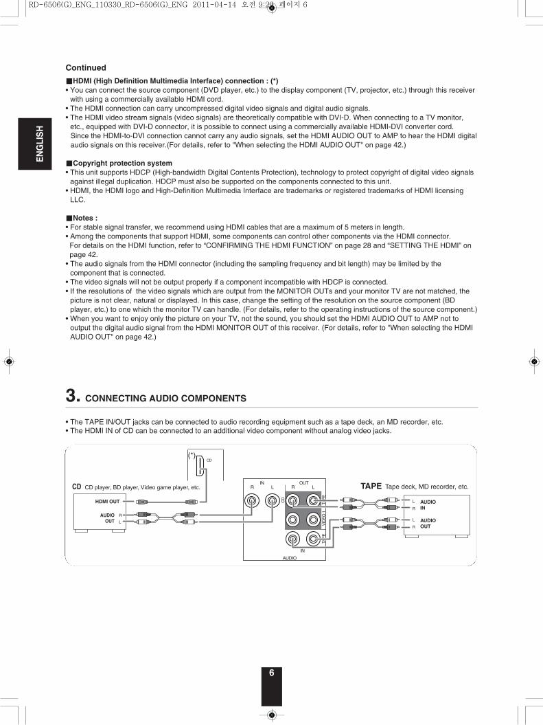
3. CONNECTING AUDIO COMPONENTS• The TAPE IN/OUT jacks can be connected to audio recording equipment such as a tape deck, an MD recorder, etc.• The HDMI IN of CD can be connected to an additional video component without analog video jacks.
Continued
RD-6506(G)_ENG_110330_RD-6506(G)_ENG 2011-04-14 오전 9:29 페이지 6
ENGLISH
7
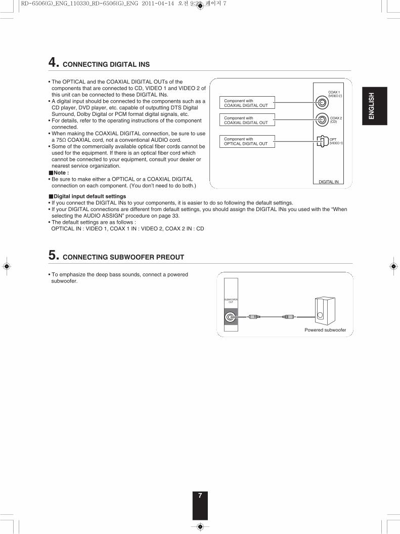
5. CONNECTING SUBWOOFER PREOUT• To emphasize the deep bass sounds, connect a powered subwoofer.
SUBWOOFEROUT
4. CONNECTING DIGITAL INS• The OPTICAL and the COAXIAL DIGITAL OUTs of the
components that are connected to CD, VIDEO 1 and VIDEO 2 ofthis unit can be connected to these DIGITAL INs.
• A digital input should be connected to the components such as aCD player, DVD player, etc. capable of outputting DTS DigitalSurround, Dolby Digital or PCM format digital signals, etc.
• For details, refer to the operating instructions of the componentconnected.
• When making the COAXIAL DIGITAL connection, be sure to usea 75Ω COAXIAL cord, not a conventional AUDIO cord.
• Some of the commercially available optical fiber cords cannot beused for the equipment. If there is an optical fiber cord whichcannot be connected to your equipment, consult your dealer ornearest service organization.
■Note :• Be sure to make either a OPTICAL or a COAXIAL DIGITAL
connection on each component. (You don’t need to do both.)
■Digital input default settings• If you connect the DIGITAL INs to your components, it is easier to do so following the default settings.• If your DIGITAL connections are different from default settings, you should assign the DIGITAL INs you used with the “When
selecting the AUDIO ASSIGN” procedure on page 33.• The default settings are as follows : OPTICAL IN : VIDEO 1, COAX 1 IN : VIDEO 2, COAX 2 IN : CD
DIGITAL IN
COAX 2(CD)
OPT(VIDEO 1)
COAX 1(VIDEO 2)
RD-6506(G)_ENG_110330_RD-6506(G)_ENG 2011-04-14 오전 9:29 페이지 7

ENGLISH
8
6. CONNECTING SPEAKERS
SPEAKERS
R L R L
SURROUND(6 )
CENTER(6 )
FRONT(6 )
• Be sure to connect speakers firmly and correctlyaccording to the channel(left and right) and the polarity(+ and -). If the connections are faulty, no sound will beheard from the speakers, and if the polarity of the speakerconnection is incorrect, the sound will be unnatural andlack bass.
• For installing the speakers, refer to "Speaker placement"on page 9.
• After installing the speakers, first adjust the speakersettings according to your environment and speakerlayout.(For details, refer to "SETTING THE SPEAKER SETUP"on page 34.)
Caution :• Be sure to use the speakers with the impedance of 6
ohms or above.• Do not let the bare speaker wires touch each other or any
metal part of this unit. This could damage this unit and/orthe speakers.
• Never touch the speaker terminals while the AC inputcord is connected to the wall AC outlet. Doing so couldresult in electric shocks.
■Connecting speaker wire
1. Strip away approx. 10 mm(3/8 inch) of wire insulation,then twist the wire endstight.
2. Loosen by turning thespeaker terminal counter-clockwise.
3. Insert the bare part of thewire.
4. Tighten by turning itclockwise.
8. TERMINAL FOR UPGRADES• This terminal may be used in the future to update the operating software so that it will be able to support new digital audio
formats, etc.
■Note :• Programming for upgrades requires specialized programming knowledge and for that reason we recommend that it only be
done by qualified installers.
7. AC INPUT CORD• Plug the cord into a wall AC outlet.
RD-6506(G)_ENG_110330_RD-6506(G)_ENG 2011-04-14 오전 9:29 페이지 8
ENGLISH
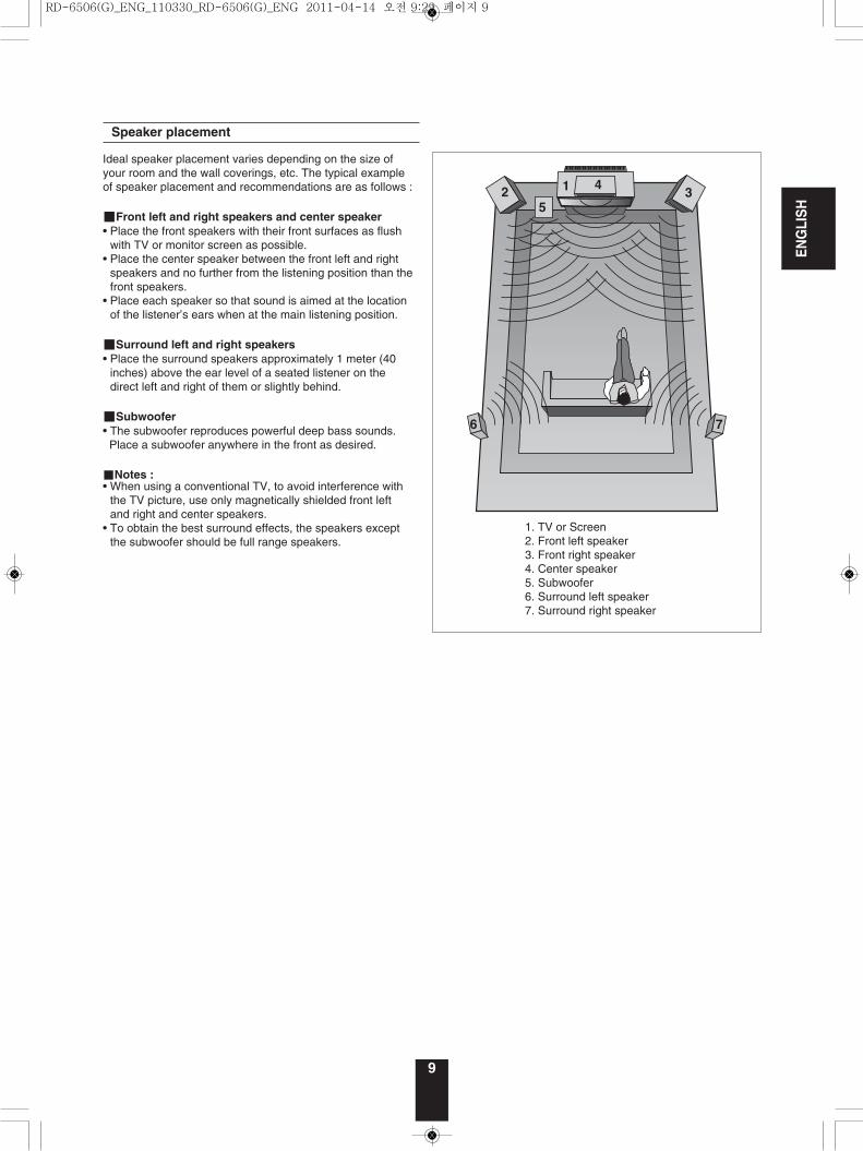
Ideal speaker placement varies depending on the size ofyour room and the wall coverings, etc. The typical exampleof speaker placement and recommendations are as follows :
■Front left and right speakers and center speaker• Place the front speakers with their front surfaces as flush
with TV or monitor screen as possible.• Place the center speaker between the front left and right
speakers and no further from the listening position than thefront speakers.
• Place each speaker so that sound is aimed at the locationof the listener’s ears when at the main listening position.
■Surround left and right speakers• Place the surround speakers approximately 1 meter (40
inches) above the ear level of a seated listener on thedirect left and right of them or slightly behind.
■Subwoofer• The subwoofer reproduces powerful deep bass sounds.Place a subwoofer anywhere in the front as desired.
■Notes :• When using a conventional TV, to avoid interference with
the TV picture, use only magnetically shielded front leftand right and center speakers.
• To obtain the best surround effects, the speakers exceptthe subwoofer should be full range speakers.
Speaker placement
9
1. TV or Screen2. Front left speaker3. Front right speaker4. Center speaker5. Subwoofer6. Surround left speaker7. Surround right speaker
RD-6506(G)_ENG_110330_RD-6506(G)_ENG 2011-04-14 오전 9:29 페이지 9
ENGLISH
10
Front Panel Controls
ON / STANDBY AUTO / MANUAL SURROUND STEREO VIDEO AUDIO
SOUND INPUT
AUDIO ASSIGNSPEAKER
ON / OFF
TONE CH.LEVEL SETUP ENTER / MEMO BANDPRESETTUNEPHONES
AUX 1 AUX 2
POWER
AUDIO / VIDEO RECEIVER RD-6506
ON OFF
RETURN MAIN MENU
MASTER VOLUME
6 81 2
9 10 12 1413 15 16 17 18 19 20 21 22
73 4 11 5
■FLUORESCENT DISPLAY
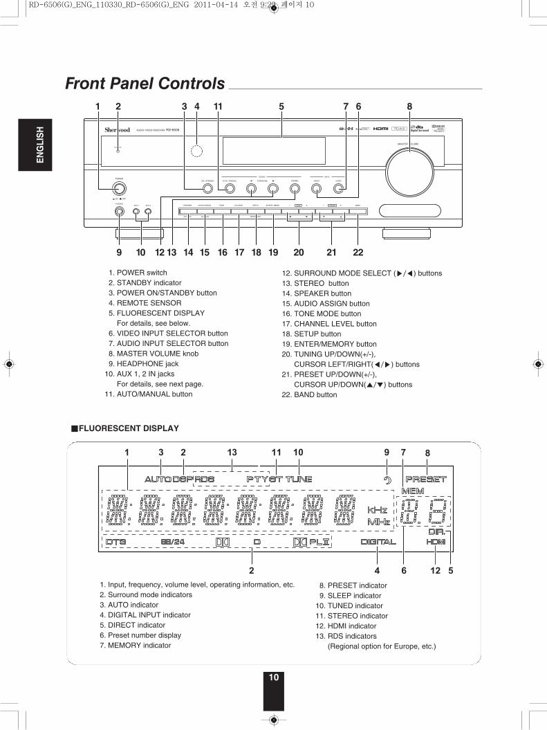
1. Input, frequency, volume level, operating information, etc.2. Surround mode indicators3. AUTO indicator4. DIGITAL INPUT indicator5. DIRECT indicator6. Preset number display7. MEMORY indicator
8. PRESET indicator9. SLEEP indicator
10. TUNED indicator11. STEREO indicator12. HDMI indicator13. RDS indicators
(Regional option for Europe, etc.)
1. POWER switch2. STANDBY indicator 3. POWER ON/STANDBY button4. REMOTE SENSOR 5. FLUORESCENT DISPLAY
For details, see below.6. VIDEO INPUT SELECTOR button7. AUDIO INPUT SELECTOR button8. MASTER VOLUME knob 9. HEADPHONE jack
10. AUX 1, 2 IN jacks For details, see next page.
11. AUTO/MANUAL button
12. SURROUND MODE SELECT (▶/◀) buttons 13. STEREO button 14. SPEAKER button 15. AUDIO ASSIGN button 16. TONE MODE button17. CHANNEL LEVEL button18. SETUP button19. ENTER/MEMORY button 20. TUNING UP/DOWN(+/-),
CURSOR LEFT/RIGHT(◀/▶) buttons21. PRESET UP/DOWN(+/-),
CURSOR UP/DOWN(▲/▼) buttons22. BAND button
RD-6506(G)_ENG_110330_RD-6506(G)_ENG 2011-04-14 오전 9:29 페이지 10
ENGLISH
11
AUX 1 AUX 2
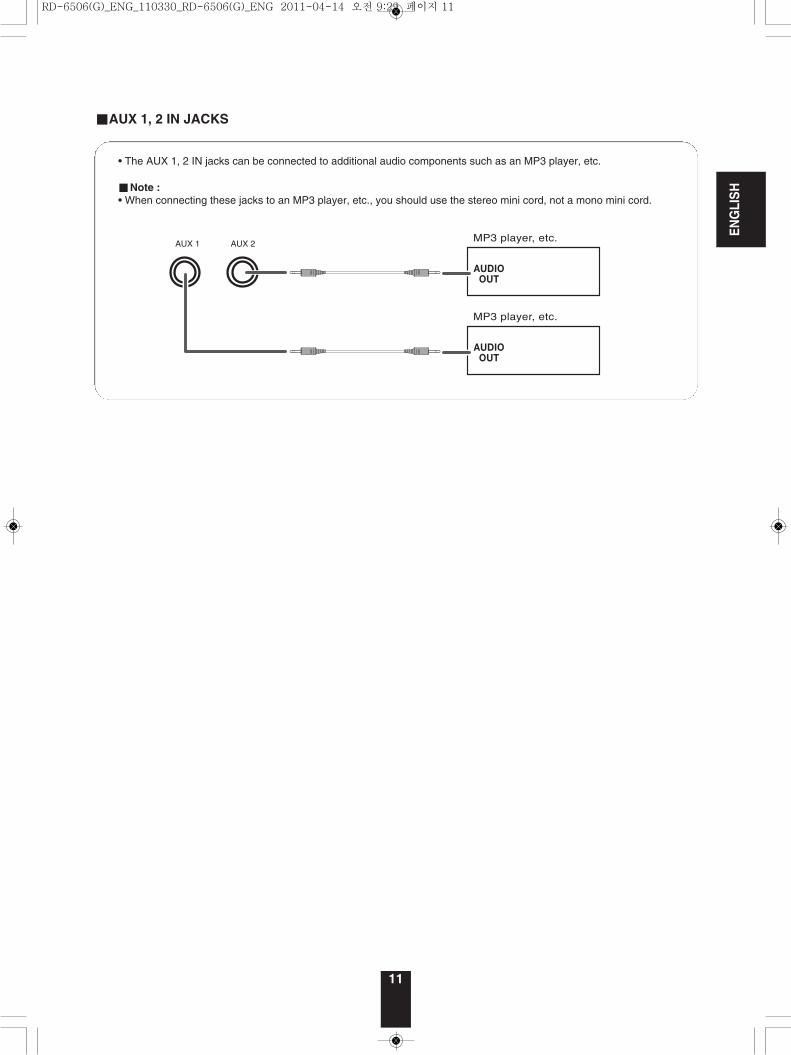
• The AUX 1, 2 IN jacks can be connected to additional audio components such as an MP3 player, etc.
■Note :• When connecting these jacks to an MP3 player, etc., you should use the stereo mini cord, not a mono mini cord.
■AUX 1, 2 IN JACKS
RD-6506(G)_ENG_110330_RD-6506(G)_ENG 2011-04-14 오전 9:29 페이지 11
ENGLISH
12
Remote Controls
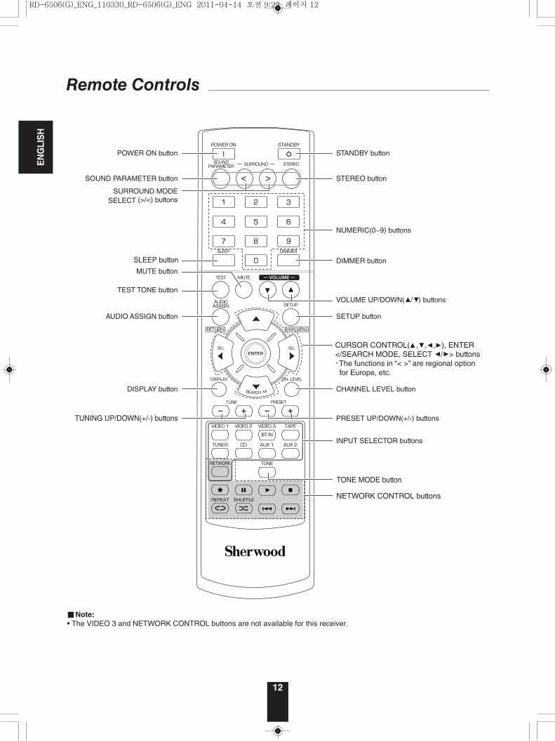
CURSOR CONTROL( , , , ), ENTER </SEARCH MODE, SELECT / > buttons The functions in “< >” are regional option for Europe, etc.
NETWORK CONTROL buttons
■Note:• The VIDEO 3 and NETWORK CONTROL buttons are not available for this receiver.
RD-6506(G)_ENG_110330_RD-6506(G)_ENG 2011-04-14 오전 9:29 페이지 12
ENGLISH
13
ON / STANDBY AUTO / MANUAL SURROUND STEREO VIDEO AUDIO
SOUND INPUT
AUDIO ASSIGNSPEAKER
ON / OFF
TONE CH.LEVEL SETUP ENTER / MEMO BANDPRESETTUNEPHONES
AUX 1 AUX 2
POWER
AUDIO / VIDEO RECEIVER RD-6506
ON OFF
RETURN MAIN MENU
MASTER VOLUME
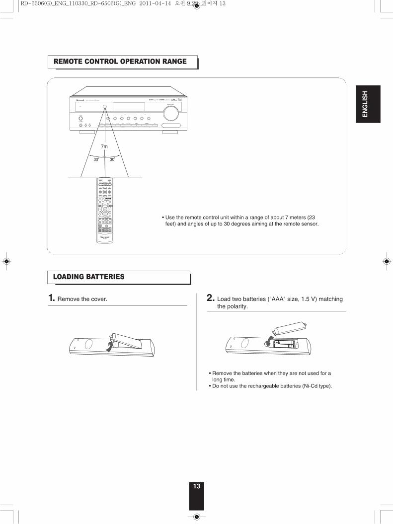
LOADING BATTERIES
REMOTE CONTROL OPERATION RANGE
• Use the remote control unit within a range of about 7 meters (23feet) and angles of up to 30 degrees aiming at the remote sensor.
• Remove the batteries when they are not used for along time.
• Do not use the rechargeable batteries (Ni-Cd type).
1. Remove the cover. 2. Load two batteries ("AAA" size, 1.5 V) matchingthe polarity.
RD-6506(G)_ENG_110330_RD-6506(G)_ENG 2011-04-14 오전 9:29 페이지 13
ENGLISH
Operations
LISTENING TO A PROGRAM SOURCE
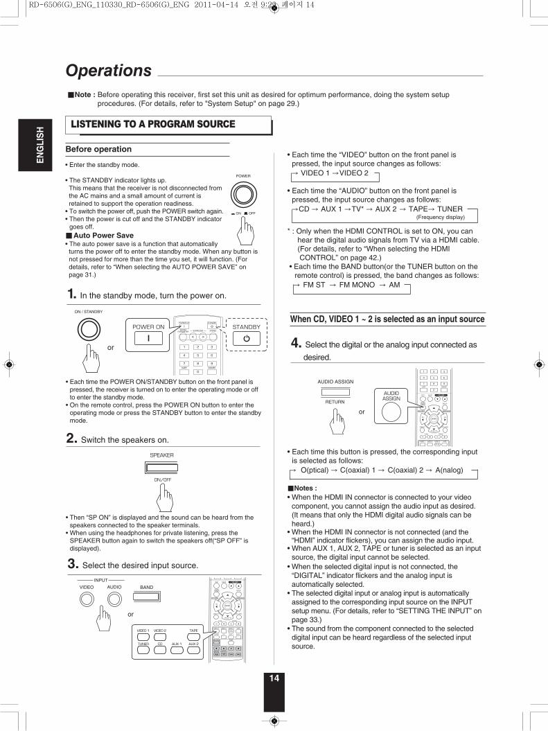
Before operation
• Enter the standby mode.
• The STANDBY indicator lights up.This means that the receiver is not disconnected fromthe AC mains and a small amount of current isretained to support the operation readiness.
• To switch the power off, push the POWER switch again.• Then the power is cut off and the STANDBY indicator
goes off.■Auto Power Save• The auto power save is a function that automatically
• Each time the POWER ON/STANDBY button on the front panel ispressed, the receiver is turned on to enter the operating mode or offto enter the standby mode.
• On the remote control, press the POWER ON button to enter theoperating mode or press the STANDBY button to enter the standbymode.
POWER
ON OFF
ON / STANDBY
1. In the standby mode, turn the power on.
3. Select the desired input source.
14
■Note : Before operating this receiver, first set this unit as desired for optimum performance, doing the system setupprocedures. (For details, refer to "System Setup" on page 29.)
• Then “SP ON” is displayed and the sound can be heard from thespeakers connected to the speaker terminals.
• When using the headphones for private listening, press theSPEAKER button again to switch the speakers off(“SP OFF” isdisplayed).
2. Switch the speakers on.
• Each time the “VIDEO” button on the front panel ispressed, the input source changes as follows:→ VIDEO 1 →VIDEO 2
• Each time the “AUDIO” button on the front panel ispressed, the input source changes as follows:→CD → AUX 1 →TV* → AUX 2 → TAPE→ TUNER
(Frequency display)
* : Only when the HDMI CONTROL is set to ON, you can hear the digital audio signals from TV via a HDMI cable. (For details, refer to “When selecting the HDMI CONTROL” on page 42.)
• Each time the BAND button(or the TUNER button on theremote control) is pressed, the band changes as follows:→ FM ST → FM MONO → AM
When CD, VIDEO 1 ~ 2 is selected as an input source
AUDIO ASSIGN
RETURN
4. Select the digital or the analog input connected as
desired.
• Each time this button is pressed, the corresponding inputis selected as follows:→ O(ptical) → C(oaxial) 1 → C(oaxial) 2 → A(nalog)
■Notes :• When the HDMI IN connector is connected to your video
component, you cannot assign the audio input as desired.(It means that only the HDMI digital audio signals can beheard.)
• When the HDMI IN connector is not connected (and the“HDMI” indicator flickers), you can assign the audio input.
• When AUX 1, AUX 2, TAPE or tuner is selected as an inputsource, the digital input cannot be selected.
• When the selected digital input is not connected, the“DIGITAL” indicator flickers and the analog input isautomatically selected.
• The selected digital input or analog input is automaticallyassigned to the corresponding input source on the INPUTsetup menu. (For details, refer to “SETTING THE INPUT” onpage 33.)
• The sound from the component connected to the selecteddigital input can be heard regardless of the selected inputsource.
INPUT
BANDAUDIOVIDEO
turns the power off to enter the standby mode. When any button isnot pressed for more than the time you set, it will function. (Fordetails, refer to “When selecting the AUTO POWER SAVE” onpage 31.)
RD-6506(G)_ENG_110330_RD-6506(G)_ENG 2011-04-14 오전 9:29 페이지 14
ENGLISH
15
TONE
TUNE
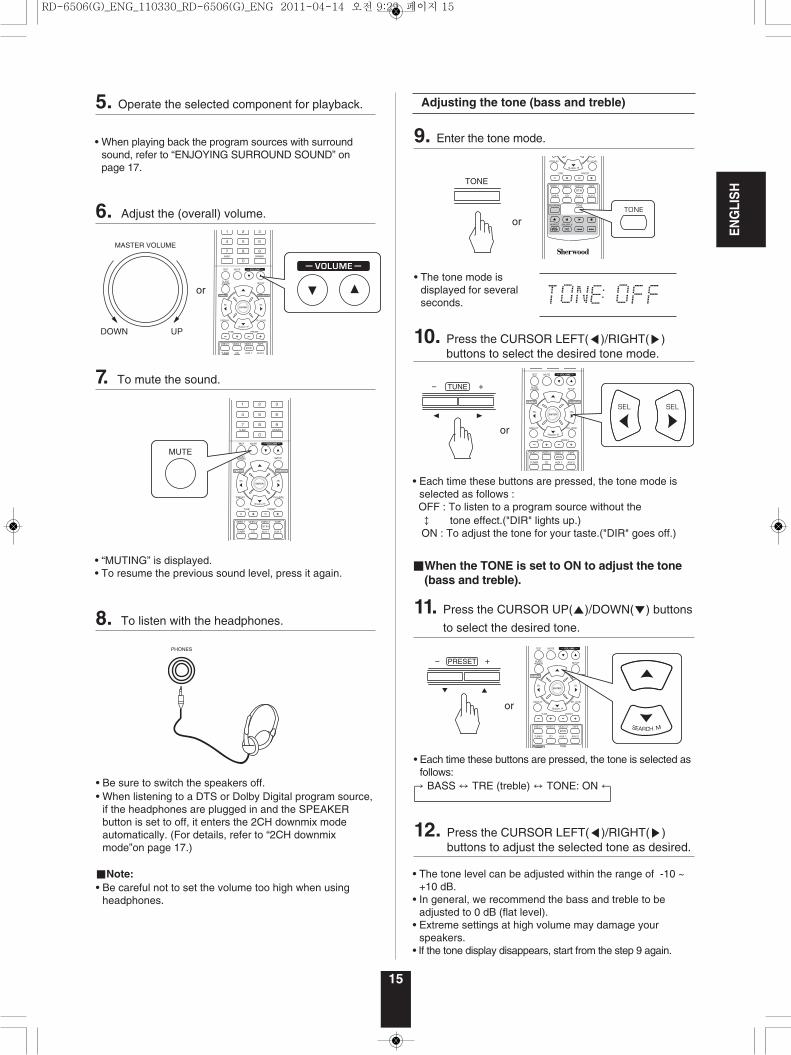
• Each time these buttons are pressed, the tone mode isselected as follows : OFF : To listen to a program source without the ↕ tone effect.("DIR" lights up.)ON : To adjust the tone for your taste.("DIR" goes off.)
• Each time these buttons are pressed, the tone is selected asfollows:
→ BASS ↔ TRE (treble) ↔ TONE: ON ←
■When the TONE is set to ON to adjust the tone(bass and treble).
• The tone level can be adjusted within the range of -10 ~+10 dB.
• In general, we recommend the bass and treble to beadjusted to 0 dB (flat level).
• Extreme settings at high volume may damage yourspeakers.
• If the tone display disappears, start from the step 9 again.
Adjusting the tone (bass and treble)
• The tone mode isdisplayed for severalseconds.
9. Enter the tone mode.
10. Press the CURSOR LEFT(◀)/RIGHT(▶)buttons to select the desired tone mode.
11. Press the CURSOR UP(▲)/DOWN(▼) buttons
to select the desired tone.
12. Press the CURSOR LEFT(◀)/RIGHT(▶)buttons to adjust the selected tone as desired.
PRESET
• Be sure to switch the speakers off.• When listening to a DTS or Dolby Digital program source,
if the headphones are plugged in and the SPEAKERbutton is set to off, it enters the 2CH downmix modeautomatically. (For details, refer to “2CH downmixmode”on page 17.)
■Note:• Be careful not to set the volume too high when using
headphones.
• When playing back the program sources with surroundsound, refer to “ENJOYING SURROUND SOUND” onpage 17.
• “MUTING” is displayed.• To resume the previous sound level, press it again.
MASTER VOLUME
DOWN UP
MUTE
PHONES
5. Operate the selected component for playback.
6. Adjust the (overall) volume.
7. To mute the sound.
8. To listen with the headphones.
RD-6506(G)_ENG_110330_RD-6506(G)_ENG 2011-04-14 오전 9:29 페이지 15
ENGLISH
16
SURROUND SOUND
• This receiver incorporates a sophisticated Digital Signal Processor that allows you to create optimum sound quality and soundatmosphere in your personal Home Theater.
■DTS Digital Surround DTS Digital Surround(also called simply DTS) supports up to5.1 discrete channels and uses less compression for highfidelity reproduction. Use it with DVDs and CDs bearing theDTS logo.
■DTS 96/24 This is high resolution DTS with a 96 kHz sampling rate and24 bit resolution, providing superior fidelity. Use it with DVDsbearing the DTS 96/24 logo.
Manufactured under license under U.S. Patent Nos:5,956,674; 5,974,380; 6,487,535 & other U.S. and worldwidepatents issued & pending. DTS, the Symbol, & DTS and theSymbol together are registered trademarks & DTS DigitalSurround and the DTS logos are trademarks of DTS, Inc.Product includes software. ⓒ DTS, Inc. All Rights Reserved.
■Dolby DigitalDolby Digital is the multi-channel digital signal formatdeveloped by Dolby Laboratories. Discs bearing the DolbyDigital logo includes the recording of up to 5.1 channels ofdigital signals, which can reproduce much better soundquality, spatial expansion and dynamic rangecharacteristics than the previous Dolby Surround effect.
■Dolby Pro Logic II surroundThis mode applies conventional 2- channel signals such asdigital PCM or analog stereo signals as well as DolbySurround signals, etc. to surround processing to offerimprovements over conventional Dolby Pro Logic circuits.Dolby Pro Logic ll surround includes 2 modes as follows:
• Dolby Pro Logic ll MovieWhen enjoying movies, this mode allows you to furtherenhance the cinematic quality by adding processing thatemphasizes the sounds of the action special effects.
• Dolby Pro Logic ll MusicWhen listening to music, this mode allows you to furtherenhance the sound quality by adding processing thatemphasizes the musical effects.
■Dolby Pro LogicThis mode expands any 2-channel source(including DolbySurround source) for 4 channel(front left, center, front rightand surround) playback.The surround channel is monaural, but is played throughtwo surround speakers.
Manufactured under license from Dolby Laboratories.Dolby, Pro Logic, and the double-D symbol are registeredtrademarks of Dolby Laboratories.
• The following modes apply conventional 2-channelsignals such as digital PCM or analog stereo signals tohigh performance Digital Signal Processor to recreatesound fields artificially. Select one of the 6 providedsurround modes according to the program source youwant to play.
■Theater This mode provides the effect of being in a theater whenwatching a play.
■Movie This mode provides the effect of being in a movie theaterwhen watching a movie.
■Hall This mode provides the ambience of a concert hall forclassical music sources such as orchestral, chamber musicor an instrumental solo.
■GameThis mode is suitable for video games.
■StadiumThis mode provides the expansive sound field to achievethe true stadium effect when watching baseball or soccergames.
■Multi CH StereoThis mode is designed for playing background music. Thefront and surround channels create a stereo image thatencompasses the entire area.
Surround modes
RD-6506(G)_ENG_110330_RD-6506(G)_ENG 2011-04-14 오전 9:29 페이지 16
17
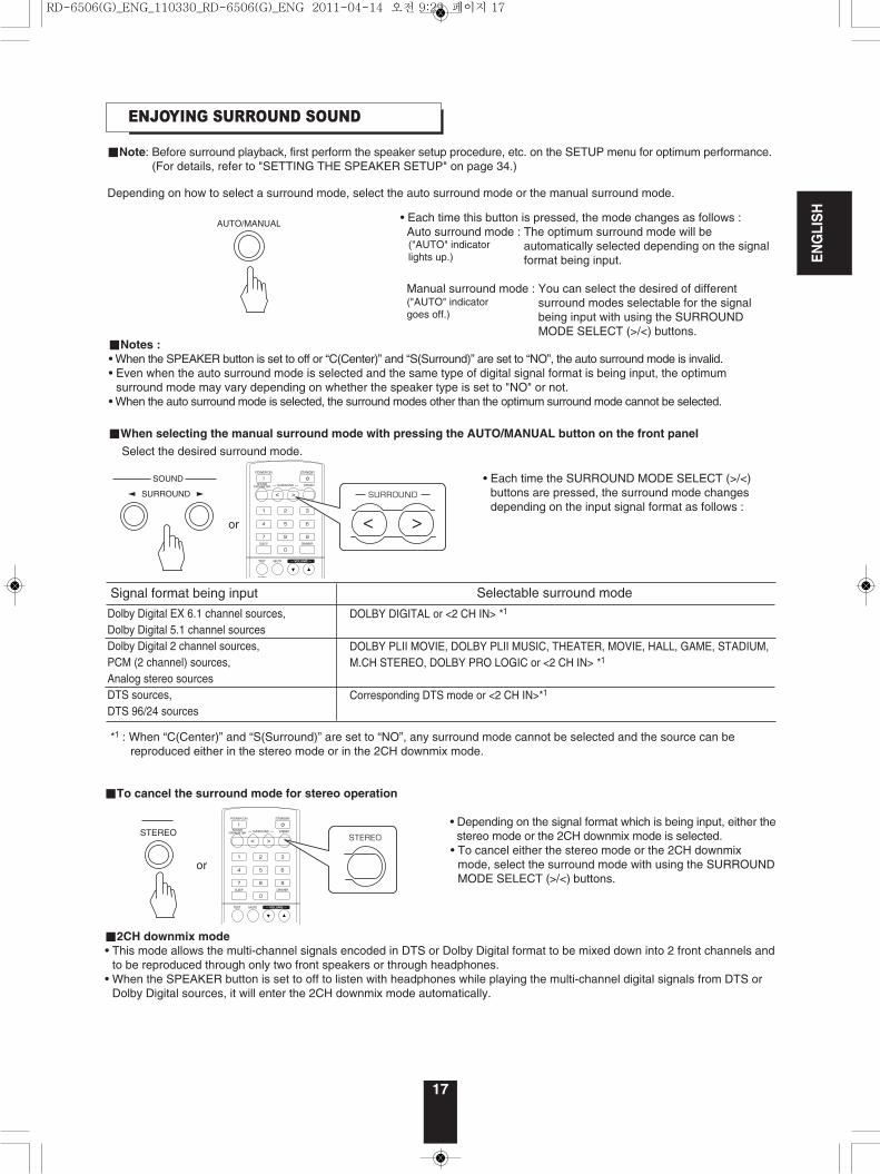
ENJOYING SURROUND SOUND
• Each time this button is pressed, the mode changes as follows :Auto surround mode : The optimum surround mode will be
automatically selected depending on the signalformat being input.
Manual surround mode : You can select the desired of differentsurround modes selectable for the signalbeing input with using the SURROUNDMODE SELECT (>/<) buttons.
*1 : When “C(Center)” and “S(Surround)” are set to “NO”, any surround mode cannot be selected and the source can be reproduced either in the stereo mode or in the 2CH downmix mode.
■Notes : • When the SPEAKER button is set to off or “C(Center)” and “S(Surround)” are set to “NO”, the auto surround mode is invalid.• Even when the auto surround mode is selected and the same type of digital signal format is being input, the optimum
surround mode may vary depending on whether the speaker type is set to "NO" or not.• When the auto surround mode is selected, the surround modes other than the optimum surround mode cannot be selected.
■When selecting the manual surround mode with pressing the AUTO/MANUAL button on the front panel
Select the desired surround mode.
■Note: Before surround playback, first perform the speaker setup procedure, etc. on the SETUP menu for optimum performance.(For details, refer to "SETTING THE SPEAKER SETUP" on page 34.)
Depending on how to select a surround mode, select the auto surround mode or the manual surround mode.
("AUTO" indicatorlights up.)
("AUTO" indicatorgoes off.)
• Each time the SURROUND MODE SELECT (>/<)buttons are pressed, the surround mode changesdepending on the input signal format as follows :
AUTO/MANUAL
SOUND
SURROUND
DOLBY DIGITAL or <2 CH IN> *1
DOLBY PLII MOVIE, DOLBY PLII MUSIC, THEATER, MOVIE, HALL, GAME, STADIUM,M.CH STEREO, DOLBY PRO LOGIC or <2 CH IN> *1
Corresponding DTS mode or <2 CH IN>*1
Dolby Digital EX 6.1 channel sources,Dolby Digital 5.1 channel sourcesDolby Digital 2 channel sources,PCM (2 channel) sources, Analog stereo sourcesDTS sources,DTS 96/24 sources
Signal format being input Selectable surround mode
ENGLISH
■To cancel the surround mode for stereo operation
• Depending on the signal format which is being input, either thestereo mode or the 2CH downmix mode is selected.
• To cancel either the stereo mode or the 2CH downmixmode, select the surround mode with using the SURROUNDMODE SELECT (>/<) buttons.
■2CH downmix mode• This mode allows the multi-channel signals encoded in DTS or Dolby Digital format to be mixed down into 2 front channels and
to be reproduced through only two front speakers or through headphones.• When the SPEAKER button is set to off to listen with headphones while playing the multi-channel digital signals from DTS or
Dolby Digital sources, it will enter the 2CH downmix mode automatically.
STEREO
RD-6506(G)_ENG_110330_RD-6506(G)_ENG 2011-04-14 오전 9:29 페이지 17
ENGLISH
18
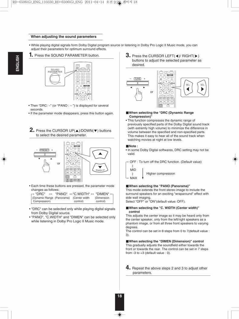
• While playing digital signals form Dolby Digital program source or listening in Dolby Pro Logic II Music mode, you canadjust their parameters for optimum surround effects.
• Then “DRC: ~” (or “PANO : ~ ”) is displayed for severalseconds.
• If the parameter mode disappears, press this button again.
When adjusting the sound parameters
1. Press the SOUND PARAMETER button.
PRESET
2. Press the CURSOR UP(▲)/DOWN(▼) buttonsto select the desired parameter.
• Each time these buttons are pressed, the parameter modechanges as follows:→ "DRC" ↔ "PANO" ↔"C.WIDTH" ↔ "DIMEN" ←(Dynamic Range (Panorama) (Center width (DimensionCompression) control) control)
• "DRC" can be selected only while playing digital signalsfrom Dolby Digital source.
• "PANO", "C.WIDTH" and "DIMEN" can be selected onlywhile listening in Dolby Pro Logic II Music mode.
■When selecting the "DRC (Dynamic Range Compression)"
• This function compresses the dynamic range ofpreviously specified parts of the Dolby Digital sound track(with extremly high volume) to minimize the difference involume between the specified and non-specified parts.This makes it easy to hear all of the sound track whenwatching movies at night at low levels.
■Note :• In some Dolby Digital softwares, DRC setting may not be
valid.
→ OFF : To turn off the DRC function. (Default value)↕
MID ↕
→ MAX
■When selecting the "PANO (Panorama)" This mode extends the front stereo image to include thesurround speakers for an exciting "wraparound" effect withside wall imaging. Select "OFF" or "ON"(default value: OFF).
■When selecting the "C. WIDTH (Center width)"control
This adjusts the center image so it may be heard only fromthe center speaker, only from the left/right speakers as aphantom image, or from all three front speakers to varyingdegrees.The control can be set in 8 steps from 0 to 7(default value :3).
■When selecting the "DIMEN (Dimension)" controlThis gradually adjusts the soundfield either towards thefront or towards the rear. The control can be set in 7 stepsfrom -3 to +3 (default value : 0).
TUNE
3. Press the CURSOR LEFT(◀)/ RIGHT(▶)buttons to adjust the selected parameter asdesired.
4. Repeat the above steps 2 and 3 to adjust other parameters.
Higher compression
RD-6506(G)_ENG_110330_RD-6506(G)_ENG 2011-04-14 오전 9:29 페이지 18
ENGLISH
19
TUNE
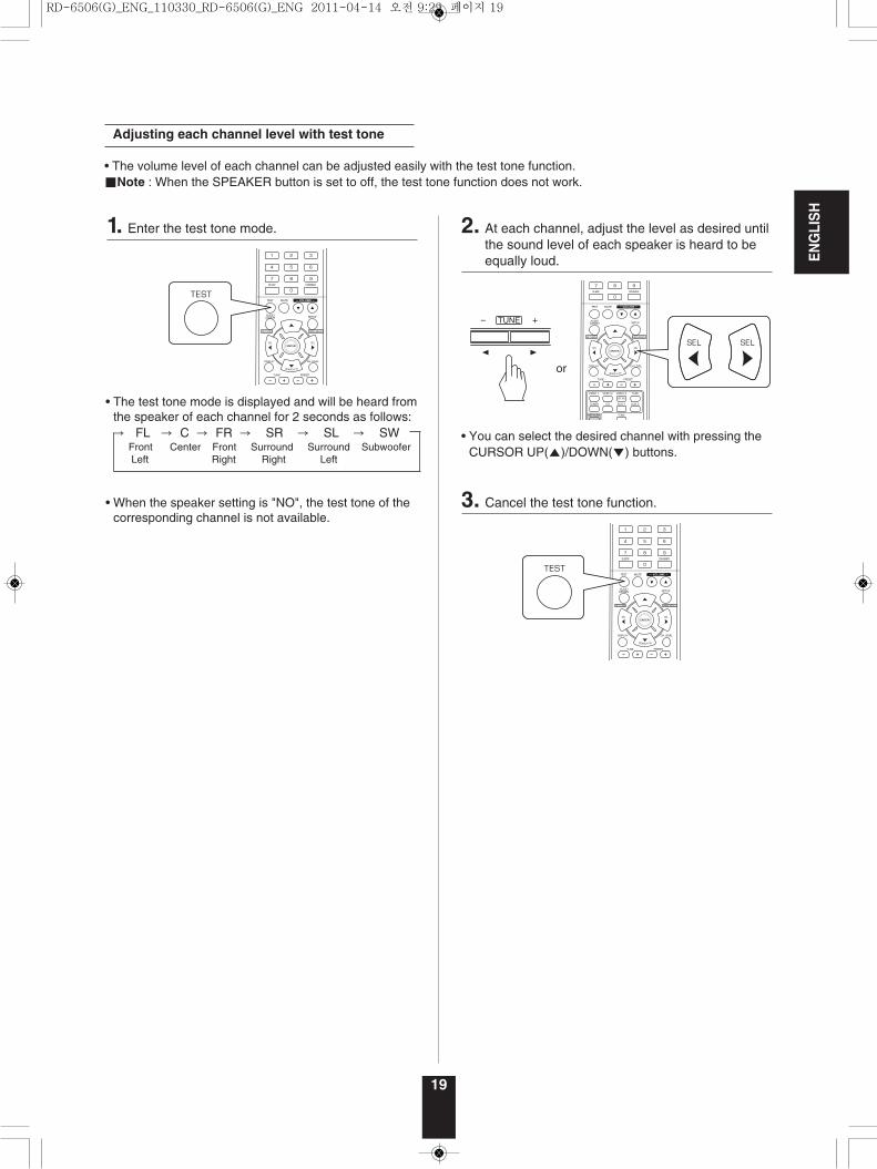
• The volume level of each channel can be adjusted easily with the test tone function.■Note : When the SPEAKER button is set to off, the test tone function does not work.
Adjusting each channel level with test tone
• The test tone mode is displayed and will be heard fromthe speaker of each channel for 2 seconds as follows:→ FL → C → FR → SR → SL → SW
Front Center Front Surround Surround SubwooferLeft Right Right Left
• When the speaker setting is "NO", the test tone of thecorresponding channel is not available.
1. Enter the test tone mode. 2. At each channel, adjust the level as desired untilthe sound level of each speaker is heard to beequally loud.
3. Cancel the test tone function.
• You can select the desired channel with pressing theCURSOR UP(▲)/DOWN(▼) buttons.
RD-6506(G)_ENG_110330_RD-6506(G)_ENG 2011-04-14 오전 9:29 페이지 19
ENGLISH
20
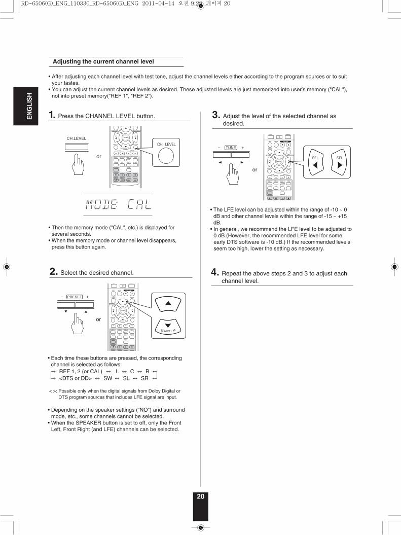
Adjusting the current channel level
• Each time these buttons are pressed, the correspondingchannel is selected as follows:→ REF 1, 2 (or CAL) ↔ L ↔ C ↔ R ←→ <DTS or DD> ↔ SW ↔ SL ↔ SR ←
< >: Possible only when the digital signals from Dolby Digital orDTS program sources that includes LFE signal are input.
• Depending on the speaker settings ("NO") and surroundmode, etc., some channels cannot be selected.
• When the SPEAKER button is set to off, only the FrontLeft, Front Right (and LFE) channels can be selected.
• After adjusting each channel level with test tone, adjust the channel levels either according to the program sources or to suityour tastes.
• You can adjust the current channel levels as desired. These adjusted levels are just memorized into user’s memory ("CAL"),not into preset memory("REF 1", "REF 2").
• The LFE level can be adjusted within the range of -10 ~ 0dB and other channel levels within the range of -15 ~ +15dB.
• In general, we recommend the LFE level to be adjusted to0 dB.(However, the recommended LFE level for someearly DTS software is -10 dB.) If the recommended levelsseem too high, lower the setting as necessary.
CH.LEVEL
PRESET
• Then the memory mode ("CAL", etc.) is displayed forseveral seconds.
• When the memory mode or channel level disappears,press this button again.
TUNE
1. Press the CHANNEL LEVEL button.
2. Select the desired channel.
3. Adjust the level of the selected channel asdesired.
4. Repeat the above steps 2 and 3 to adjust eachchannel level.
RD-6506(G)_ENG_110330_RD-6506(G)_ENG 2011-04-14 오전 9:29 페이지 20
ENGLISH
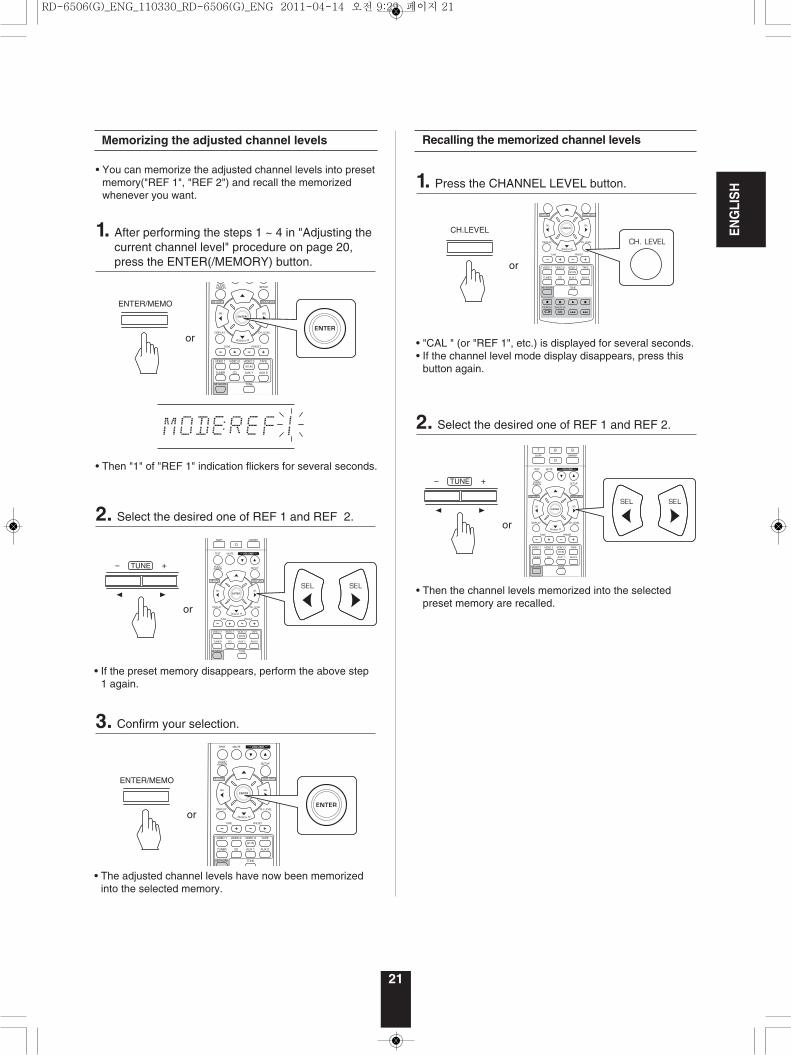
Memorizing the adjusted channel levels
• Then "1" of "REF 1" indication flickers for several seconds.
• You can memorize the adjusted channel levels into presetmemory("REF 1", "REF 2") and recall the memorizedwhenever you want.
• "CAL " (or "REF 1", etc.) is displayed for several seconds.• If the channel level mode display disappears, press this
button again.
• The adjusted channel levels have now been memorizedinto the selected memory.
ENTER/MEMO
ENTER/MEMO
TUNE
TUNE
• If the preset memory disappears, perform the above step1 again.
1. After performing the steps 1 ~ 4 in "Adjusting thecurrent channel level" procedure on page 20,press the ENTER(/MEMORY) button.
Recalling the memorized channel levels
• Then the channel levels memorized into the selectedpreset memory are recalled.
CH.LEVEL
2. Select the desired one of REF 1 and REF 2.
3. Confirm your selection.
1. Press the CHANNEL LEVEL button.
2. Select the desired one of REF 1 and REF 2.
21
RD-6506(G)_ENG_110330_RD-6506(G)_ENG 2011-04-14 오전 9:29 페이지 21
ENGLISH
22
LISTENING TO RADIO BROADCASTS
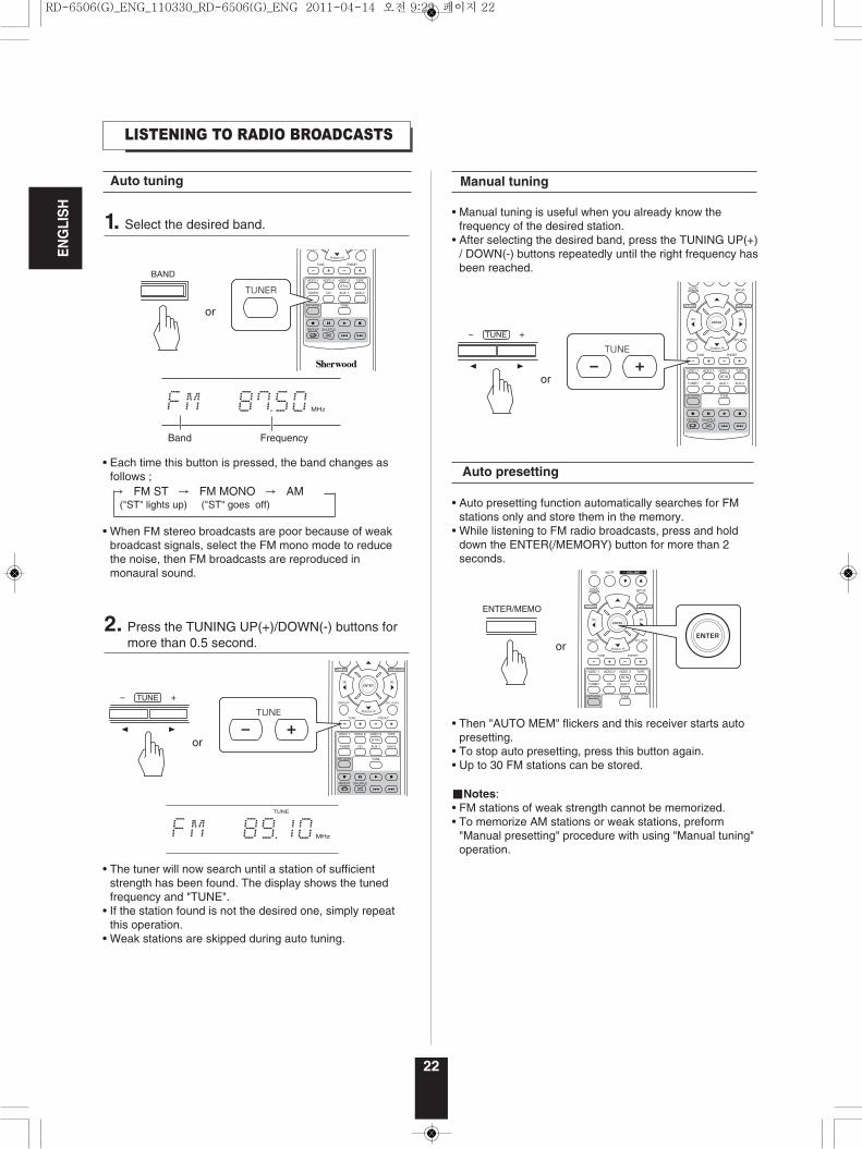
Auto tuning
• Each time this button is pressed, the band changes asfollows ;→ FM ST → FM MONO → AM
("ST" lights up) ("ST" goes off)
• When FM stereo broadcasts are poor because of weakbroadcast signals, select the FM mono mode to reducethe noise, then FM broadcasts are reproduced inmonaural sound.
• Manual tuning is useful when you already know thefrequency of the desired station.
• After selecting the desired band, press the TUNING UP(+)/ DOWN(-) buttons repeatedly until the right frequency hasbeen reached.
Manual tuning
TUNE
TUNE
• The tuner will now search until a station of sufficientstrength has been found. The display shows the tunedfrequency and "TUNE".
• If the station found is not the desired one, simply repeatthis operation.
• Weak stations are skipped during auto tuning.
1. Select the desired band.
2. Press the TUNING UP(+)/DOWN(-) buttons formore than 0.5 second.
Auto presetting
• Auto presetting function automatically searches for FMstations only and store them in the memory.
• While listening to FM radio broadcasts, press and holddown the ENTER(/MEMORY) button for more than 2seconds.
• Then "AUTO MEM" flickers and this receiver starts autopresetting.
• To stop auto presetting, press this button again.• Up to 30 FM stations can be stored.
■Notes:• FM stations of weak strength cannot be memorized.• To memorize AM stations or weak stations, preform
"Manual presetting" procedure with using "Manual tuning"operation.
ENTER/MEMO
BAND
RD-6506(G)_ENG_110330_RD-6506(G)_ENG 2011-04-14 오전 9:29 페이지 22
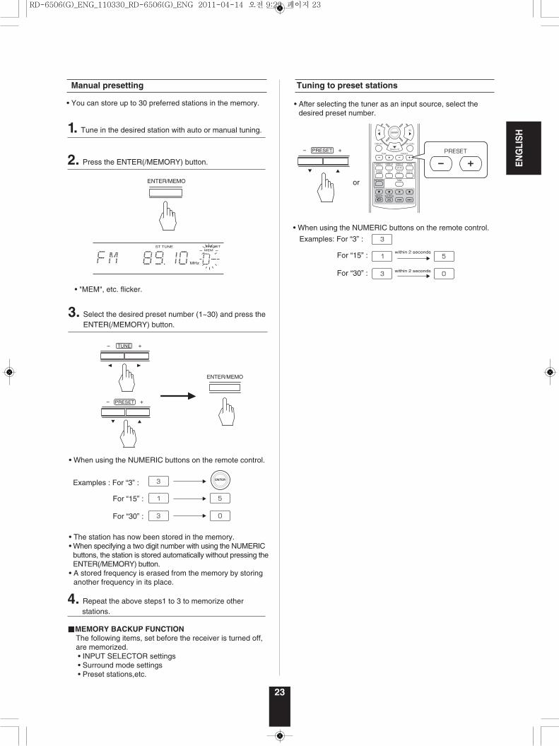
• When using the NUMERIC buttons on the remote control.
Examples: For “3” :
For “15” :
For “30” :
Tuning to preset stations
PRESET
ENTER/MEMO
TUNE
PRESET
3. Select the desired preset number (1~30) and press theENTER(/MEMORY) button.
4. Repeat the above steps1 to 3 to memorize other stations.
■MEMORY BACKUP FUNCTIONThe following items, set before the receiver is turned off, are memorized.• INPUT SELECTOR settings• Surround mode settings• Preset stations,etc.
• When using the NUMERIC buttons on the remote control.
Examples : For “3” :
For “15” :
For “30” :
• The station has now been stored in the memory.• When specifying a two digit number with using the NUMERIC
buttons, the station is stored automatically without pressing theENTER(/MEMORY) button.
• A stored frequency is erased from the memory by storinganother frequency in its place.
• After selecting the tuner as an input source, select thedesired preset number.
23
ENGLISH
Manual presetting
• You can store up to 30 preferred stations in the memory.
• "MEM", etc. flicker.
ENTER/MEMO
1. Tune in the desired station with auto or manual tuning.
2. Press the ENTER(/MEMORY) button.
RD-6506(G)_ENG_110330_RD-6506(G)_ENG 2011-04-14 오전 9:29 페이지 23
ENGLISH
24
LISTENING TO RDS BROADCASTS(FM ONLY)
RDS Tuner (Regional Option for some countries in Europe, etc.)
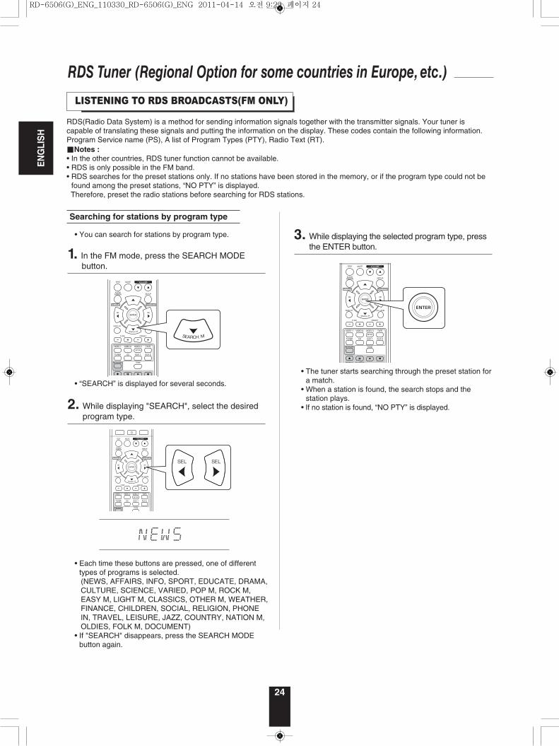
• You can search for stations by program type.
RDS(Radio Data System) is a method for sending information signals together with the transmitter signals. Your tuner iscapable of translating these signals and putting the information on the display. These codes contain the following information.Program Service name (PS), A list of Program Types (PTY), Radio Text (RT).■Notes :• In the other countries, RDS tuner function cannot be available.• RDS is only possible in the FM band.• RDS searches for the preset stations only. If no stations have been stored in the memory, or if the program type could not be
found among the preset stations, “NO PTY” is displayed.Therefore, preset the radio stations before searching for RDS stations.
Searching for stations by program type
• The tuner starts searching through the preset station fora match.
• When a station is found, the search stops and thestation plays.
• If no station is found, “NO PTY” is displayed.
• “SEARCH” is displayed for several seconds.
1. In the FM mode, press the SEARCH MODE button.
3. While displaying the selected program type, pressthe ENTER button.
• Each time these buttons are pressed, one of differenttypes of programs is selected. (NEWS, AFFAIRS, INFO, SPORT, EDUCATE, DRAMA,CULTURE, SCIENCE, VARIED, POP M, ROCK M,EASY M, LIGHT M, CLASSICS, OTHER M, WEATHER,FINANCE, CHILDREN, SOCIAL, RELIGION, PHONEIN, TRAVEL, LEISURE, JAZZ, COUNTRY, NATION M,OLDIES, FOLK M, DOCUMENT)
• If "SEARCH" disappears, press the SEARCH MODEbutton again.
2. While displaying "SEARCH", select the desiredprogram type.
RD-6506(G)_ENG_110330_RD-6506(G)_ENG 2011-04-14 오전 9:29 페이지 24
ENGLISH
25
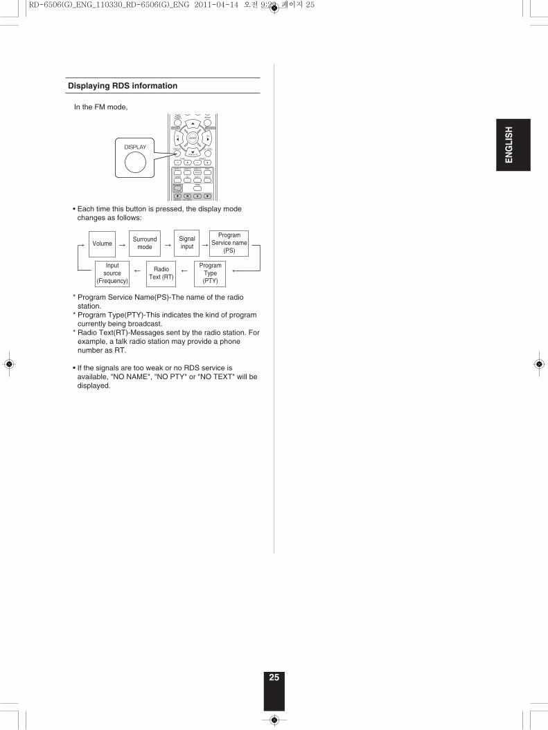
• Each time this button is pressed, the display modechanges as follows:
* Program Service Name(PS)-The name of the radiostation.
* Program Type(PTY)-This indicates the kind of programcurrently being broadcast.
* Radio Text(RT)-Messages sent by the radio station. Forexample, a talk radio station may provide a phonenumber as RT.
• If the signals are too weak or no RDS service isavailable, "NO NAME", "NO PTY" or "NO TEXT" will bedisplayed.
Displaying RDS information
VolumeSurround
mode
Inputsource
(Frequency)
RadioText (RT)
ProgramType(PTY)
Signalinput
ProgramService name
(PS)→ → → →
← ← ←
In the FM mode,
RD-6506(G)_ENG_110330_RD-6506(G)_ENG 2011-04-14 오전 9:29 페이지 25
ENGLISH
26
RECORDING
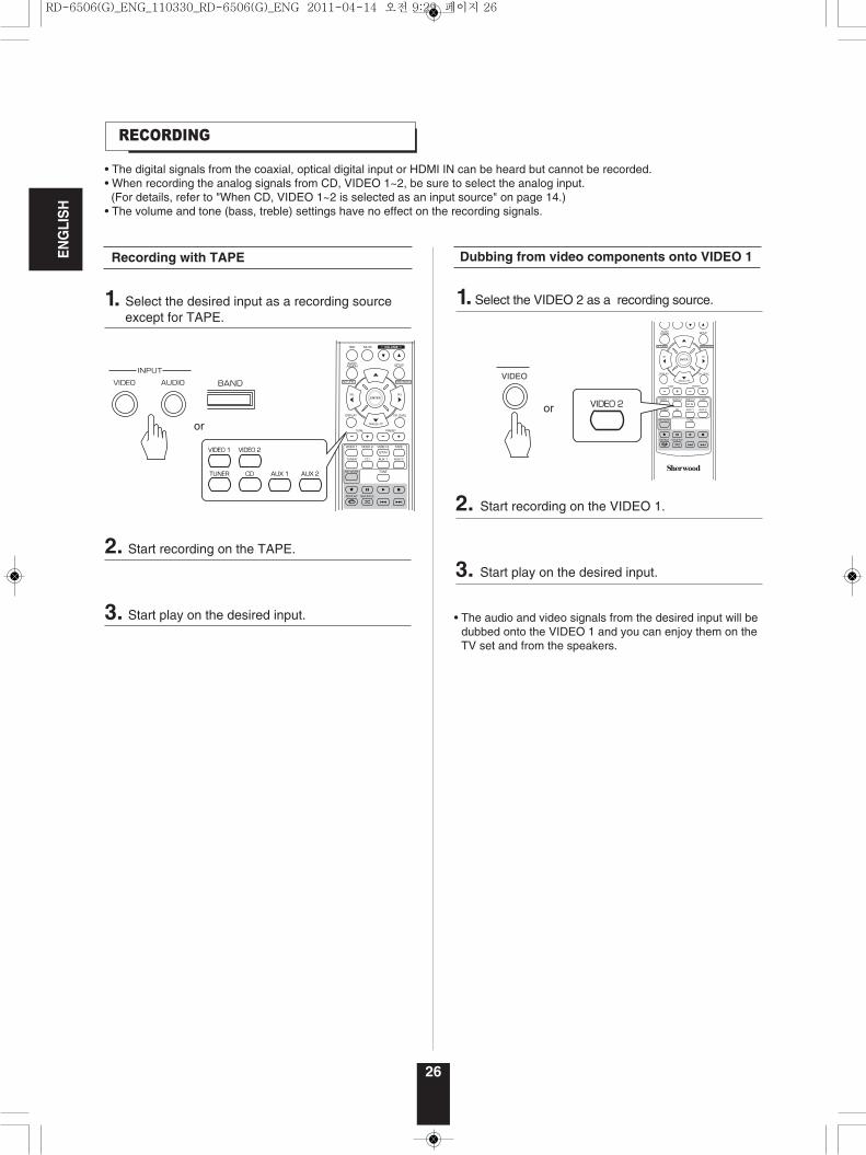
• The digital signals from the coaxial, optical digital input or HDMI IN can be heard but cannot be recorded.• When recording the analog signals from CD, VIDEO 1~2, be sure to select the analog input. (For details, refer to "When CD, VIDEO 1~2 is selected as an input source" on page 14.)
• The volume and tone (bass, treble) settings have no effect on the recording signals.
• The audio and video signals from the desired input will bedubbed onto the VIDEO 1 and you can enjoy them on theTV set and from the speakers.
Dubbing from video components onto VIDEO 1
1. Select the VIDEO 2 as a recording source.
2. Start recording on the VIDEO 1.
3. Start play on the desired input.
VIDEO
Recording with TAPE
1. Select the desired input as a recording sourceexcept for TAPE.
2. Start recording on the TAPE.
3. Start play on the desired input.
RD-6506(G)_ENG_110330_RD-6506(G)_ENG 2011-04-14 오전 9:29 페이지 26
27
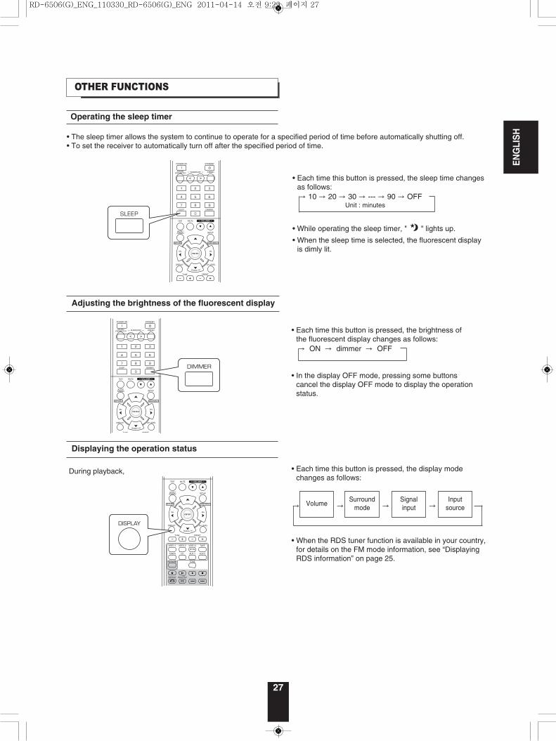
Operating the sleep timer
• The sleep timer allows the system to continue to operate for a specified period of time before automatically shutting off.• To set the receiver to automatically turn off after the specified period of time.
Adjusting the brightness of the fluorescent display
OTHER FUNCTIONS
Displaying the operation status
• Each time this button is pressed, the sleep time changesas follows:→ 10 → 20 → 30 → --- → 90 → OFF
Unit : minutes
• While operating the sleep timer, " " lights up.
• When the sleep time is selected, the fluorescent displayis dimly lit.
• Each time this button is pressed, the brightness ofthe fluorescent display changes as follows:→ ON → dimmer → OFF
• In the display OFF mode, pressing some buttonscancel the display OFF mode to display the operationstatus.
During playback,
ENGLISH
• Each time this button is pressed, the display modechanges as follows:
• When the RDS tuner function is available in your country,for details on the FM mode information, see “DisplayingRDS information” on page 25.
Surroundmode
Signalinput
VolumeInput
source→ → → →
RD-6506(G)_ENG_110330_RD-6506(G)_ENG 2011-04-14 오전 9:29 페이지 27
28
Before operation
To use the HDMI control functions properly, it is recommend to confirm the HDMI control functions usable with eachconnected component by performing the following operations.
■Note :• Some HDMI control functions may not work with certain components and TV that are not compatible with them.
• Check that this receiver, TV and player, etc are connected by HDMI cabels.• Check that the HDMI control of TV and the HDMI-connectable player are enabled.(For details on the setups of TV and player, refer to their operating instructions.)
• Set the HDMI CONTROL and the POWER CONROL to ON to enable the HDMI control of this receiver.(For details, refer to “SETTING THE HDMI” on page 42.)
• Confirm that its picture is displayed and the sound is heard from the speakers properly.
Confirming the basic HDMI operations
CONFIRMING THE HDMI FUNCTION
1. Turn the power on for all the components connected by HDMI cables.
2. Switch the TV input to the HDMI input connected to this receiver.
3. Switch this unit input to the HDMI input source.
• Confirm that all the components are turned on and the inputs of this unit and TV are switched automatically.
• Confirm that all the components are turned off.
Confirming the HDMI control functions
1. Turn the power on for all the components connected by HDMI cables.
2. Turn the TV off to enter the standby mode.
3.With all the components off, start playback on a player (connected by HDMI cable).
ENGLISH
RD-6506(G)_ENG_110330_RD-6506(G)_ENG 2011-04-14 오전 9:29 페이지 28
System Setup
29
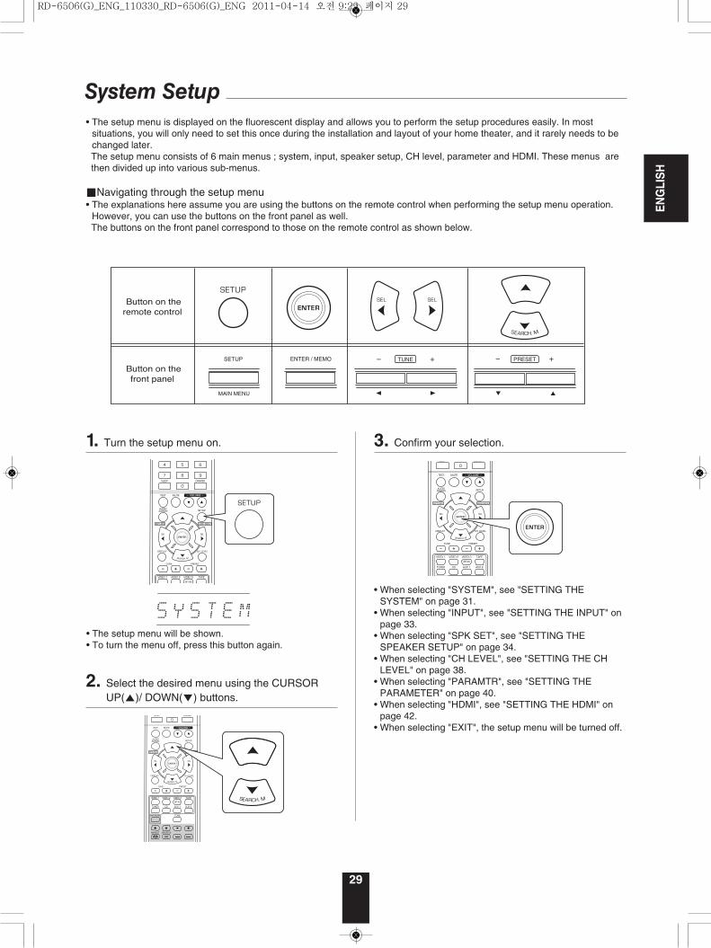
• The setup menu is displayed on the fluorescent display and allows you to perform the setup procedures easily. In mostsituations, you will only need to set this once during the installation and layout of your home theater, and it rarely needs to bechanged later. The setup menu consists of 6 main menus ; system, input, speaker setup, CH level, parameter and HDMI. These menus arethen divided up into various sub-menus.
■Navigating through the setup menu• The explanations here assume you are using the buttons on the remote control when performing the setup menu operation.
However, you can use the buttons on the front panel as well.The buttons on the front panel correspond to those on the remote control as shown below.
SETUP ENTER / MEMO PRESETTUNE
MAIN MENU
• The setup menu will be shown.• To turn the menu off, press this button again.
• When selecting "SYSTEM", see "SETTING THESYSTEM" on page 31.
• When selecting "INPUT", see "SETTING THE INPUT" onpage 33.
• When selecting "SPK SET", see "SETTING THESPEAKER SETUP" on page 34.
• When selecting "CH LEVEL", see "SETTING THE CHLEVEL" on page 38.
• When selecting "PARAMTR", see "SETTING THEPARAMETER" on page 40.
• When selecting "HDMI", see "SETTING THE HDMI" onpage 42.
• When selecting "EXIT", the setup menu will be turned off.
1. Turn the setup menu on.
2. Select the desired menu using the CURSORUP(▲)/ DOWN(▼) buttons.
3. Confirm your selection.
ENGLISH
RD-6506(G)_ENG_110330_RD-6506(G)_ENG 2011-04-14 오전 9:29 페이지 29
ENGLISH
30
SW M : NORM / SW +
TONE : OFF
A.P.S : OFF / 2H / 4H / 6H
RETURN
BASS : 0 / - 10 ~ + 10
TRE : 0 / - 10 ~ + 10
SPK SET
VID 1 CFG
VID 2 CFG
CD CFG
RETURN
CONFIG
X-OVER
DISTANCE
RETURN
MODE : CAL / REF 1 / REF 2
L : 0 dB / -15 ~ + 15
C : 0 dB / -15 ~ + 15
R : 0 dB / -15 ~ + 15
SR : 0 dB / -15 ~ + 15
SL : 0 dB / -15 ~ + 15
SW : 0 dB / -15 ~ + 15
DD : 0 dB / -10 ~ 0
DTS : 0 dB / -10 ~ 0
RETURN
DRC : OFF / MID / MAX
RETURN
PANO : OFF / ON
C.WIDTH : 3 / 0 ~ 7
DIMEN : 0 / -3 ~ +3
DRC DD
RETURN
HDMI : AMP / THRU
CEC : OFF / ON
PWR : OFF / ON
RETURN
HDMI
EXIT
AUD : OPT / COX 1 / COX 2 / - - -
AUTO : ON / OFF
RETURN
AUD : OPT / COX 1 / COX 2 / - - -
AUTO : ON / OFF
RETURN
AUD : OPT / COX 1 / COX 2 / - - -
AUTO : ON / OFF
RETURN
FC : 40 / 50 / 80 / 100 / 150 / 200
RETURN
UNIT : M / FTL : 3.0 M / 0.1 ~ 9.0
C : 3.0 M / 0.1 ~ 9.0
R : 3.0 M / 0.1 ~ 9.0
SR : 3.0 M / 0.1 ~ 9.0
SL : 3.0 M / 0.1 ~ 9.0
SW : 3.0 M / 0.1 ~ 9.0
RETURN
L : 10.0 FT / 0.5 ~ 30.0
C : 10.0 FT / 0.5 ~ 30.0
R : 10.0 FT / 0.5 ~ 30.0
SR : 10.0 FT / 0.5 ~ 30.0
SL : 10.0 FT / 0.5 ~ 30.0
SW : 10.0 FT / 0.5 ~ 30.0
RETURN
F : LARGE / SMALL
C : LARGE / SMALL / NO
S : LARGE / SMALL / NO
SW : YES / NO
RETURN
/ ON
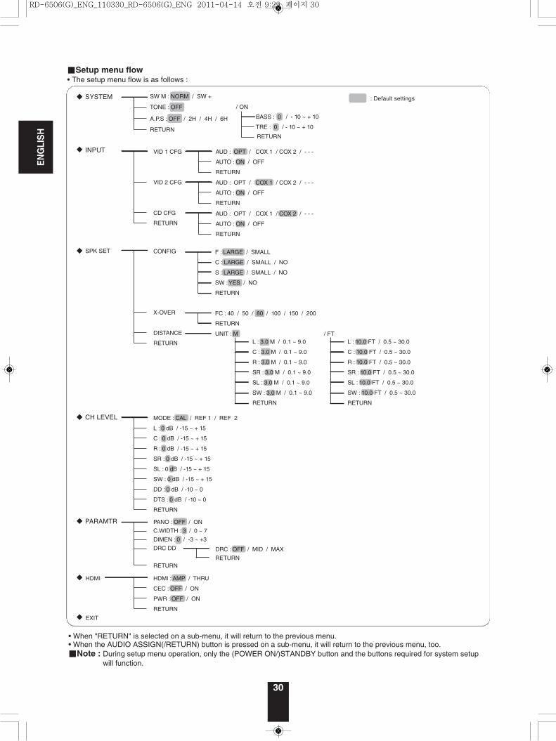
■Setup menu flow• The setup menu flow is as follows :
• When "RETURN" is selected on a sub-menu, it will return to the previous menu.• When the AUDIO ASSIGN(/RETURN) button is pressed on a sub-menu, it will return to the previous menu, too.■Note : During setup menu operation, only the (POWER ON/)STANDBY button and the buttons required for system setup
will function.
RD-6506(G)_ENG_110330_RD-6506(G)_ENG 2011-04-14 오전 9:29 페이지 30
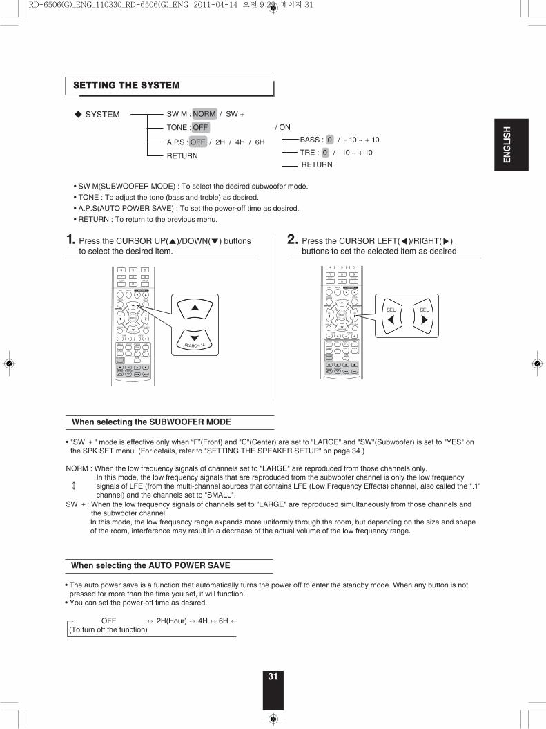
1. Press the CURSOR UP(▲)/DOWN(▼) buttonsto select the desired item.
2. Press the CURSOR LEFT(◀)/RIGHT(▶)buttons to set the selected item as desired
SETTING THE SYSTEM
31
SW M : NORM / SW +
TONE : OFF
A.P.S : OFF / 2H / 4H / 6H
RETURN
BASS : 0 / - 10 ~ + 10
TRE : 0 / - 10 ~ + 10
/ ON
• SW M(SUBWOOFER MODE) : To select the desired subwoofer mode.
• TONE : To adjust the tone (bass and treble) as desired.
• A.P.S(AUTO POWER SAVE) : To set the power-off time as desired.
• RETURN : To return to the previous menu.
ENGLISH
When selecting the SUBWOOFER MODE
• "SW +" mode is effective only when “F”(Front) and "C"(Center) are set to "LARGE" and "SW"(Subwoofer) is set to "YES" onthe SPK SET menu. (For details, refer to "SETTING THE SPEAKER SETUP" on page 34.)
NORM : When the low frequency signals of channels set to "LARGE" are reproduced from those channels only.In this mode, the low frequency signals that are reproduced from the subwoofer channel is only the low frequencysignals of LFE (from the multi-channel sources that contains LFE (Low Frequency Effects) channel, also called the ".1"channel) and the channels set to "SMALL".
SW +: When the low frequency signals of channels set to "LARGE" are reproduced simultaneously from those channels andthe subwoofer channel.In this mode, the low frequency range expands more uniformly through the room, but depending on the size and shapeof the room, interference may result in a decrease of the actual volume of the low frequency range.
↕
When selecting the AUTO POWER SAVE
• The auto power save is a function that automatically turns the power off to enter the standby mode. When any button is notpressed for more than the time you set, it will function.
• You can set the power-off time as desired.
→ OFF ↔ 2H(Hour) ↔ 4H ↔ 6H ←(To turn off the function)
RD-6506(G)_ENG_110330_RD-6506(G)_ENG 2011-04-14 오전 9:29 페이지 31
ENGLISH
32
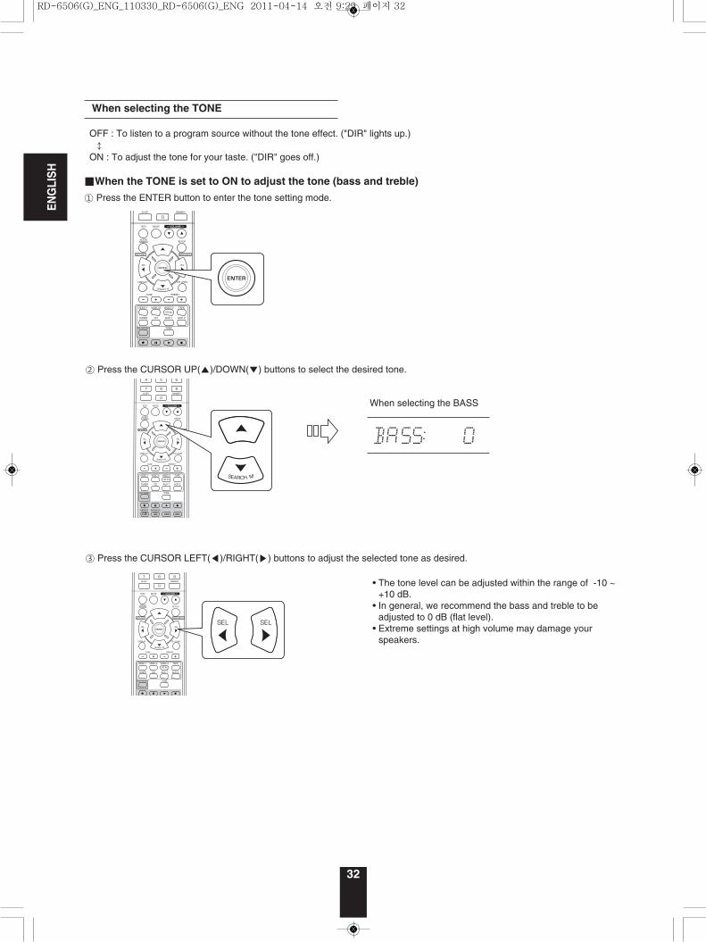
OFF : To listen to a program source without the tone effect. ("DIR" lights up.)↕
ON : To adjust the tone for your taste. ("DIR" goes off.)
■When the TONE is set to ON to adjust the tone (bass and treble)
① Press the ENTER button to enter the tone setting mode.
• The tone level can be adjusted within the range of -10 ~+10 dB.
• In general, we recommend the bass and treble to beadjusted to 0 dB (flat level).
• Extreme settings at high volume may damage yourspeakers.
③ Press the CURSOR LEFT(◀)/RIGHT(▶) buttons to adjust the selected tone as desired.
When selecting the TONE
When selecting the BASS
② Press the CURSOR UP(▲)/DOWN(▼) buttons to select the desired tone.
RD-6506(G)_ENG_110330_RD-6506(G)_ENG 2011-04-14 오전 9:29 페이지 32
33
3. Press the CURSOR LEFT(◀)/RIGHT(▶)buttons to set the selected item as desired.
2. Press the CURSOR UP(▲)/DOWN(▼) buttonsto select the desired item.
ENGLISH
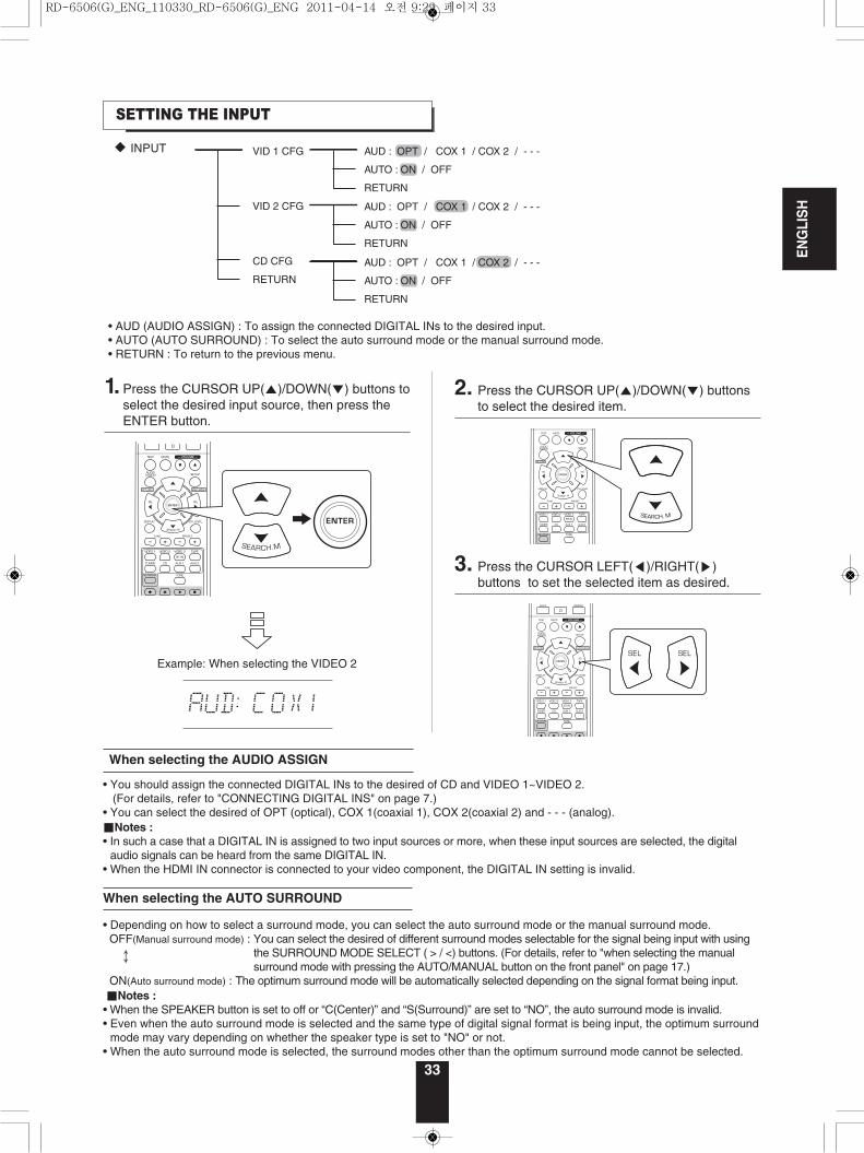
SETTING THE INPUT
VID 1 CFG
VID 2 CFG
CD CFG
RETURN
AUD : OPT / COX 1 / COX 2 / - - -
AUTO : ON / OFF
RETURN
AUD : OPT / COX 1 / COX 2 / - - -
AUTO : ON / OFF
RETURN
AUD : OPT / COX 1 / COX 2 / - - -
AUTO : ON / OFF
RETURN
• AUD (AUDIO ASSIGN) : To assign the connected DIGITAL INs to the desired input.• AUTO (AUTO SURROUND) : To select the auto surround mode or the manual surround mode.• RETURN : To return to the previous menu.
1. Press the CURSOR UP(▲)/DOWN(▼) buttons toselect the desired input source, then press theENTER button.
Example: When selecting the VIDEO 2
• You should assign the connected DIGITAL INs to the desired of CD and VIDEO 1~VIDEO 2.(For details, refer to "CONNECTING DIGITAL INS" on page 7.)
• You can select the desired of OPT (optical), COX 1(coaxial 1), COX 2(coaxial 2) and - - - (analog).■Notes :• In such a case that a DIGITAL IN is assigned to two input sources or more, when these input sources are selected, the digital
audio signals can be heard from the same DIGITAL IN.• When the HDMI IN connector is connected to your video component, the DIGITAL IN setting is invalid.
When selecting the AUDIO ASSIGN
• Depending on how to select a surround mode, you can select the auto surround mode or the manual surround mode.OFF(Manual surround mode) : You can select the desired of different surround modes selectable for the signal being input with using
the SURROUND MODE SELECT ( > / <) buttons. (For details, refer to "when selecting the manualsurround mode with pressing the AUTO/MANUAL button on the front panel" on page 17.)
ON(Auto surround mode) : The optimum surround mode will be automatically selected depending on the signal format being input.■Notes :• When the SPEAKER button is set to off or “C(Center)” and “S(Surround)” are set to “NO”, the auto surround mode is invalid.• Even when the auto surround mode is selected and the same type of digital signal format is being input, the optimum surround
mode may vary depending on whether the speaker type is set to "NO" or not.• When the auto surround mode is selected, the surround modes other than the optimum surround mode cannot be selected.
When selecting the AUTO SURROUND
↕
RD-6506(G)_ENG_110330_RD-6506(G)_ENG 2011-04-14 오전 9:29 페이지 33
ENGLISH
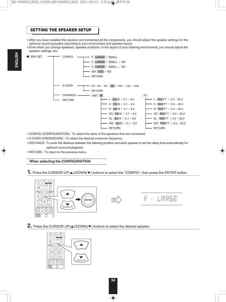
SETTING THE SPEAKER SETUP
• After you have installed this receiver and connected all the components, you should adjust the speaker settings for theoptimum sound acoustics according to your environment and speaker layout.
• Even when you change speakers, speaker positions, or the layout of your listening environment, you should adjust thespeaker settings, too.
SPK SET
CONFIG
X-OVER
DISTANCE
RETURN
FC : 40 / 50 / 80 / 100 / 150 / 200
RETURN
UNIT : M / FTL : 3.0 M / 0.1 ~ 9.0
C : 3.0 M / 0.1 ~ 9.0
R : 3.0 M / 0.1 ~ 9.0
SR : 3.0 M / 0.1 ~ 9.0
SL : 3.0 M / 0.1 ~ 9.0
SW : 3.0 M / 0.1 ~ 9.0
RETURN
L : 10.0 FT / 0.5 ~ 30.0
C : 10.0 FT / 0.5 ~ 30.0
R : 10.0 FT / 0.5 ~ 30.0
SR : 10.0 FT / 0.5 ~ 30.0
SL : 10.0 FT / 0.5 ~ 30.0
SW : 10.0 FT / 0.5 ~ 30.0
RETURN
F : LARGE / SMALL
C : LARGE / SMALL / NO
S : LARGE / SMALL / NO
SW : YES / NO
RETURN
• CONFIG (CONFIGURATION) : To select the sizes of the speakers that are connected.
• X-OVER (CROSSOVER) : To select the desired crossover frequency.
• DISTANCE: To enter the distance between the listening position and each speaker to set the delay time automatically for
optimum surround playback.
• RETURN : To return to the previous menu.
34
When selecting the CONFIGURATION
1. Press the CURSOR UP(▲)/DOWN(▼) buttons to select the "CONFIG", then press the ENTER button.
2. Press the CURSOR UP(▲)/DOWN(▼) buttons to select the desired speaker.
RD-6506(G)_ENG_110330_RD-6506(G)_ENG 2011-04-14 오전 9:29 페이지 34
ENGLISH
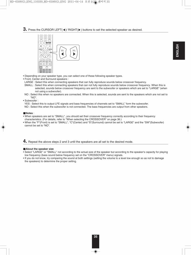
35
• Depending on your speaker type, you can select one of these following speaker types.• Front, Center and Surround speakers :LARGE : Select this when connecting speakers that can fully reproduce sounds below crossover frequency.SMALL : Select this when connecting speakers that can not fully reproduce sounds below crossover frequency. When this is
selected, sounds below crossover frequency are sent to the subwoofer or speakers which are set to "LARGE" (whennot using a subwoofer).
NO : Select this when no speakers are connected. When this is selected, sounds are sent to the speakers which are not set to"NO".
• Subwoofer :YES : Select this to output LFE signals and bass frequencies of channels set to “SMALL” form the subwoofer.NO : Select this when the subwoofer is not connected. The bass frequencies are output from other speakers.
■Notes :• When speakers are set to "SMALL", you should set their crossover frequency correctly according to their frequency
characteristics. (For details, refer to "When selecting the CROSSOVER" on page 36.)• When the "F"(Front) is set to "SMALL", “C”(Center) and “S”(Surround) cannot be set to "LARGE" and the “SW”(Subwoofer)
cannot be set to “NO”.
3. Press the CURSOR LEFT(◀)/ RIGHT(▶) buttons to set the selected speaker as desired.
4. Repeat the above steps 2 and 3 until the speakers are all set to the desired mode.
■About the speaker size• Select "LARGE" or "SMALL" not according to the actual size of the speaker but according to the speaker's capacity for playing
low frequency (bass sound below frequency set on the "CROSSOVER" menu) signals.• If you do not know, try comparing the sound at both settings (setting the volume to a level low enough so as not to damage
the speakers) to determine the proper setting.
RD-6506(G)_ENG_110330_RD-6506(G)_ENG 2011-04-14 오전 9:29 페이지 35
ENGLISH
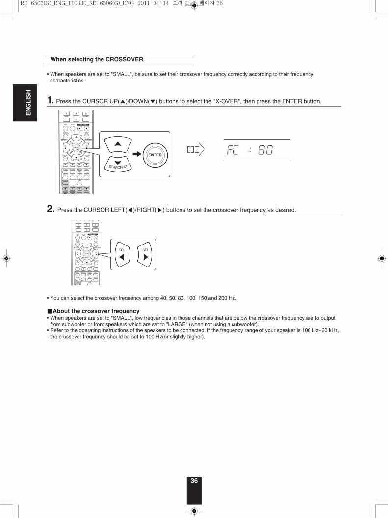
36
• You can select the crossover frequency among 40, 50, 80, 100, 150 and 200 Hz.
■About the crossover frequency• When speakers are set to "SMALL", low frequencies in those channels that are below the crossover frequency are to output
from subwoofer or front speakers which are set to "LARGE" (when not using a subwoofer).• Refer to the operating instructions of the speakers to be connected. If the frequency range of your speaker is 100 Hz~20 kHz,
the crossover frequency should be set to 100 Hz(or slightly higher).
When selecting the CROSSOVER
• When speakers are set to "SMALL", be sure to set their crossover frequency correctly according to their frequencycharacteristics.
1. Press the CURSOR UP(▲)/DOWN(▼) buttons to select the "X-OVER", then press the ENTER button.
2. Press the CURSOR LEFT(◀)/RIGHT(▶) buttons to set the crossover frequency as desired.
RD-6506(G)_ENG_110330_RD-6506(G)_ENG 2011-04-14 오전 9:29 페이지 36
ENGLISH
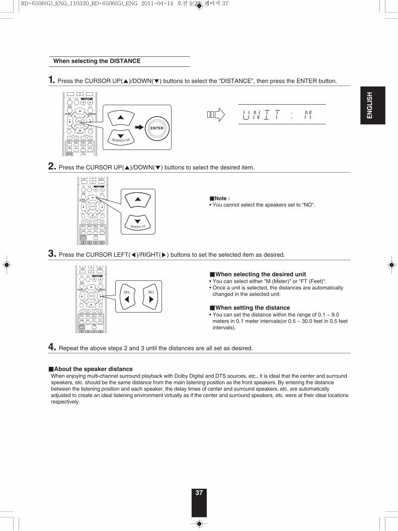
37
■When selecting the desired unit• You can select either "M (Meter)" or "FT (Feet)".• Once a unit is selected, the distances are automatically
changed in the selected unit.
■When setting the distance• You can set the distance within the range of 0.1 ~ 9.0
meters in 0.1 meter intervals(or 0.5 ~ 30.0 feet in 0.5 feetintervals).
When selecting the DISTANCE
■Note :• You cannot select the speakers set to "NO".
1. Press the CURSOR UP(▲)/DOWN(▼) buttons to select the “DISTANCE”, then press the ENTER button.
2. Press the CURSOR UP(▲)/DOWN(▼) buttons to select the desired item.
3. Press the CURSOR LEFT(◀)/RIGHT(▶) buttons to set the selected item as desired.
4. Repeat the above steps 2 and 3 until the distances are all set as desired.
■About the speaker distanceWhen enjoying multi-channel surround playback with Dolby Digital and DTS sources, etc., it is ideal that the center and surroundspeakers, etc. should be the same distance from the main listening position as the front speakers. By entering the distancebetween the listening position and each speaker, the delay times of center and surround speakers, etc. are automaticallyadjusted to create an ideal listening environment virtually as if the center and surround speakers, etc. were at their ideal locationsrespectively.
RD-6506(G)_ENG_110330_RD-6506(G)_ENG 2011-04-14 오전 9:29 페이지 37
ENGLISH
38
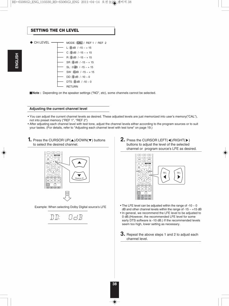
SETTING THE CH LEVEL
■Note : Depending on the speaker settings ("NO", etc), some channels cannot be selected.
• The LFE level can be adjusted within the range of -10 ~ 0dB and other channel levels within the range of -15 ~ +15 dB
• In general, we recommend the LFE level to be adjusted to0 dB.(However, the recommended LFE level for someearly DTS software is -10 dB.) If the recommended levelsseem too high, lower setting as necessary.
MODE : CAL / REF 1 / REF 2
L : 0 dB / -15 ~ + 15
C : 0 dB / -15 ~ + 15
R : 0 dB / -15 ~ + 15
SR : 0 dB / -15 ~ + 15
SL : 0 dB / -15 ~ + 15
SW : 0 dB / -15 ~ + 15
DD : 0 dB / -10 ~ 0
DTS : 0 dB / -10 ~ 0
RETURN
1. Press the CURSOR UP(▲)/DOWN(▼) buttonsto select the desired channel.
2. Press the CURSOR LEFT(◀)/RIGHT(▶)buttons to adjust the level of the selectedchannel or program source's LFE as desired.
3. Repeat the above steps 1 and 2 to adjust eachchannel level.
• You can adjust the current channel levels as desired. These adjusted levels are just memorized into user’s memory("CAL"),not into preset memory ("REF 1", "REF 2")
• After adjusting each channel level with test tone, adjust the channel levels either according to the program sources or to suityour tastes. (For details, refer to "Adjusting each channel level with test tone" on page 19.)
Adjusting the current channel level
Example: When selecting Dolby Digital source's LFE
RD-6506(G)_ENG_110330_RD-6506(G)_ENG 2011-04-14 오전 9:29 페이지 38
ENGLISH
39
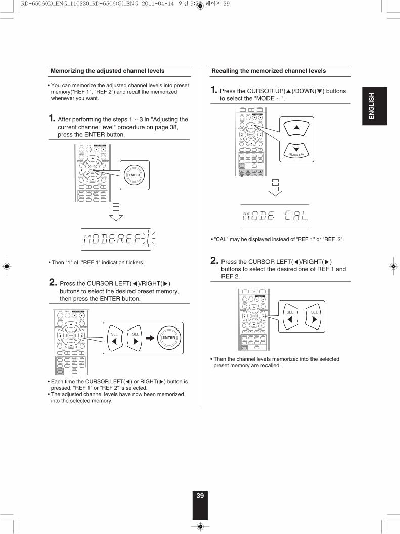
Memorizing the adjusted channel levels
• You can memorize the adjusted channel levels into presetmemory("REF 1", "REF 2") and recall the memorizedwhenever you want.
• Then "1" of "REF 1" indication flickers.
• Each time the CURSOR LEFT(◀) or RIGHT(▶) button ispressed, "REF 1" or "REF 2" is selected.
• The adjusted channel levels have now been memorizedinto the selected memory.
• "CAL" may be displayed instead of "REF 1" or "REF 2".
• Then the channel levels memorized into the selectedpreset memory are recalled.
Recalling the memorized channel levels
1. After performing the steps 1 ~ 3 in "Adjusting thecurrent channel level" procedure on page 38,press the ENTER button.
2. Press the CURSOR LEFT(◀)/RIGHT(▶)buttons to select the desired preset memory,then press the ENTER button.
1. Press the CURSOR UP(▲)/DOWN(▼) buttonsto select the "MODE ~ ".
2. Press the CURSOR LEFT(◀)/RIGHT(▶)buttons to select the desired one of REF 1 andREF 2.
RD-6506(G)_ENG_110330_RD-6506(G)_ENG 2011-04-14 오전 9:29 페이지 39
40
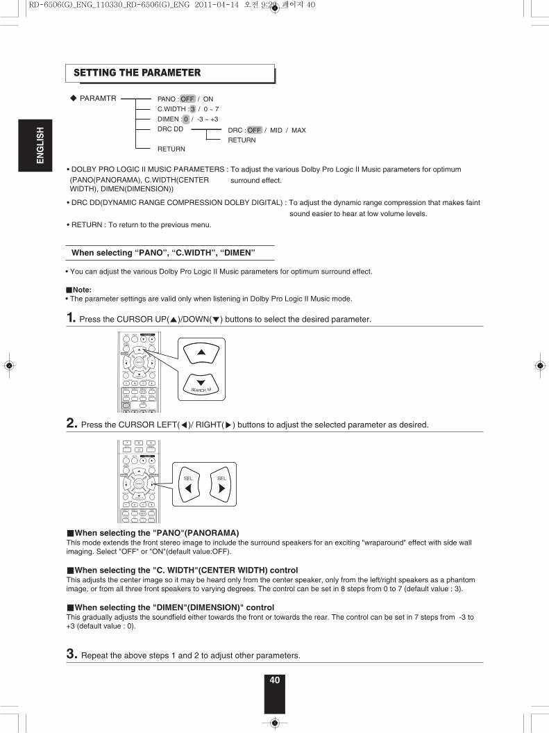
SETTING THE PARAMETER
When selecting “PANO”, “C.WIDTH”, “DIMEN”
• You can adjust the various Dolby Pro Logic II Music parameters for optimum surround effect.
■Note: • The parameter settings are valid only when listening in Dolby Pro Logic II Music mode.
DRC : OFF / MID / MAX
RETURN
PANO : OFF / ON
C.WIDTH : 3 / 0 ~ 7
DIMEN : 0 / -3 ~ +3
DRC DD
RETURN
• DOLBY PRO LOGIC II MUSIC PARAMETERS : To adjust the various Dolby Pro Logic II Music parameters for optimum
surround effect.
• DRC DD(DYNAMIC RANGE COMPRESSION DOLBY DIGITAL) : To adjust the dynamic range compression that makes faint
sound easier to hear at low volume levels.
• RETURN : To return to the previous menu.
(PANO(PANORAMA), C.WIDTH(CENTERWIDTH), DIMEN(DIMENSION))
1. Press the CURSOR UP(▲)/DOWN(▼) buttons to select the desired parameter.
■When selecting the "PANO"(PANORAMA) This mode extends the front stereo image to include the surround speakers for an exciting "wraparound" effect with side wallimaging. Select "OFF" or "ON"(default value:OFF).
■When selecting the "C. WIDTH"(CENTER WIDTH) controlThis adjusts the center image so it may be heard only from the center speaker, only from the left/right speakers as a phantomimage, or from all three front speakers to varying degrees. The control can be set in 8 steps from 0 to 7 (default value : 3).
■When selecting the "DIMEN"(DIMENSION)" controlThis gradually adjusts the soundfield either towards the front or towards the rear. The control can be set in 7 steps from -3 to+3 (default value : 0).
2. Press the CURSOR LEFT(◀)/ RIGHT(▶) buttons to adjust the selected parameter as desired.
3. Repeat the above steps 1 and 2 to adjust other parameters.
ENGLISH
RD-6506(G)_ENG_110330_RD-6506(G)_ENG 2011-04-14 오전 9:29 페이지 40
41
ENGLISH
When selecting “DRC DD”
• This function compresses the dynamic range of previously specified parts of the Dolby Digital sound track (with extremely highvolume) to minimize the difference in volume between the specified and non-specified parts.This makes it easy to hear all of the sound track when watching movies at night at low levels.
■Notes: • This setting is valid only when the digital signals from the Dolby Digital program source are being input.• In some Dolby Digital softwares, this setting may not be valid.
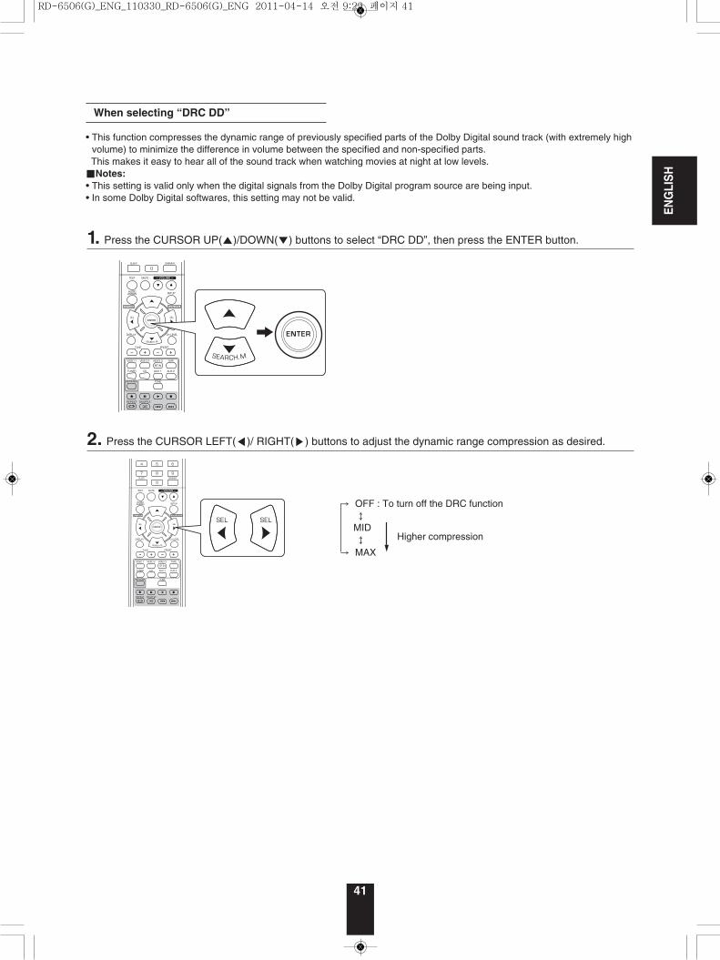
1. Press the CURSOR UP(▲)/DOWN(▼) buttons to select “DRC DD”, then press the ENTER button.
→ OFF : To turn off the DRC function↕
MID ↕
→ MAX
2. Press the CURSOR LEFT(◀)/ RIGHT(▶) buttons to adjust the dynamic range compression as desired.
Higher compression
RD-6506(G)_ENG_110330_RD-6506(G)_ENG 2011-04-14 오전 9:29 페이지 41
ENGLISH
42
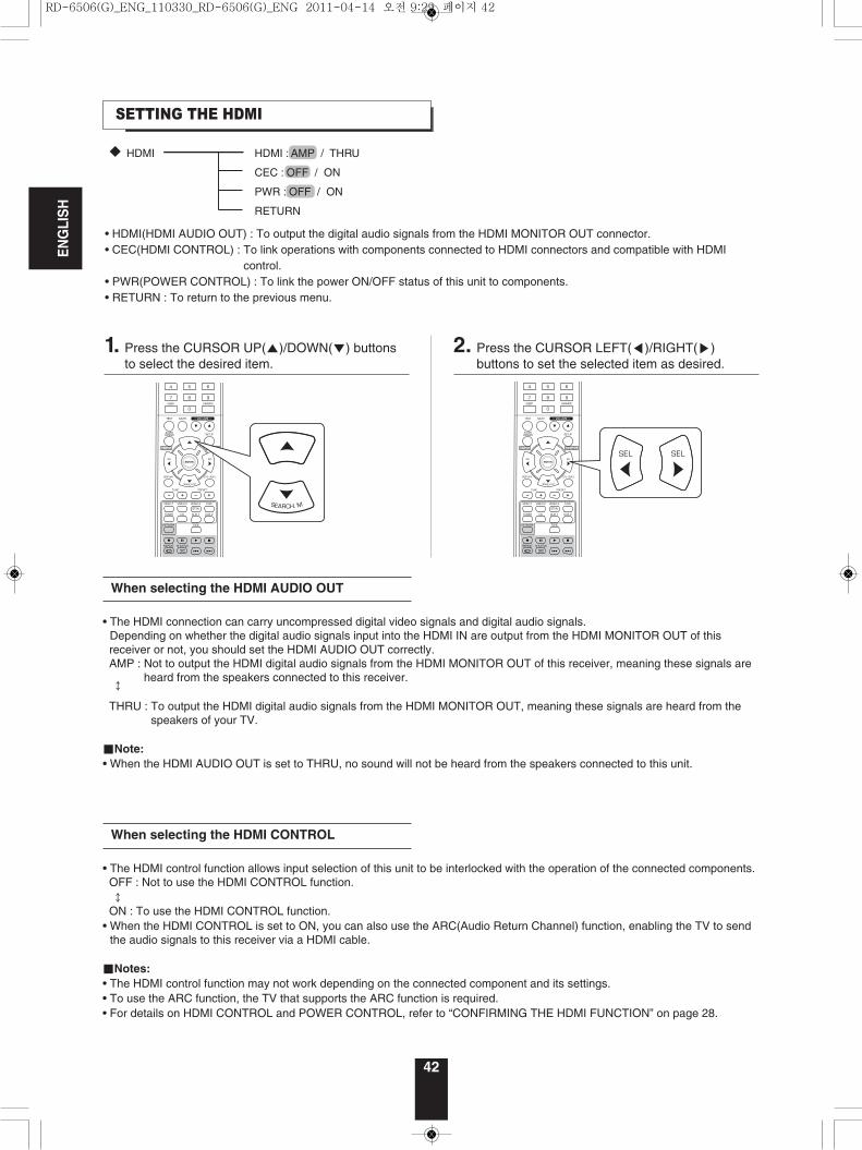
• The HDMI connection can carry uncompressed digital video signals and digital audio signals.Depending on whether the digital audio signals input into the HDMI IN are output from the HDMI MONITOR OUT of this receiver or not, you should set the HDMI AUDIO OUT correctly.AMP : Not to output the HDMI digital audio signals from the HDMI MONITOR OUT of this receiver, meaning these signals are
heard from the speakers connected to this receiver.↕
THRU : To output the HDMI digital audio signals from the HDMI MONITOR OUT, meaning these signals are heard from thespeakers of your TV.
■Note:• When the HDMI AUDIO OUT is set to THRU, no sound will not be heard from the speakers connected to this unit.
When selecting the HDMI AUDIO OUT
• The HDMI control function allows input selection of this unit to be interlocked with the operation of the connected components.OFF : Not to use the HDMI CONTROL function.↕
ON : To use the HDMI CONTROL function.• When the HDMI CONTROL is set to ON, you can also use the ARC(Audio Return Channel) function, enabling the TV to send
the audio signals to this receiver via a HDMI cable.
■Notes:• The HDMI control function may not work depending on the connected component and its settings.• To use the ARC function, the TV that supports the ARC function is required.• For details on HDMI CONTROL and POWER CONTROL, refer to “CONFIRMING THE HDMI FUNCTION” on page 28.
When selecting the HDMI CONTROL
SETTING THE HDMI
HDMI : AMP / THRU
CEC : OFF / ON
PWR : OFF / ON
RETURN
HDMI
• HDMI(HDMI AUDIO OUT) : To output the digital audio signals from the HDMI MONITOR OUT connector.• CEC(HDMI CONTROL) : To link operations with components connected to HDMI connectors and compatible with HDMI
control.• PWR(POWER CONTROL) : To link the power ON/OFF status of this unit to components.• RETURN : To return to the previous menu.
1. Press the CURSOR UP(▲)/DOWN(▼) buttonsto select the desired item.
2. Press the CURSOR LEFT(◀)/RIGHT(▶)buttons to set the selected item as desired.
RD-6506(G)_ENG_110330_RD-6506(G)_ENG 2011-04-14 오전 9:29 페이지 42
ENGLISH
43
• The Power control function allows the power status of this unit to be interlocked with the power ON/OFF and start of playbackof the connected components.OFF : Not to use the POWER CONTROL function.↕
ON : To use the POWER CONTROL function.
■Note:• The POWER CONTROL can be set only when the HDMI CONTROL is set to ON.
When selecting the POWER CONTROL
RD-6506(G)_ENG_110330_RD-6506(G)_ENG 2011-04-14 오전 9:29 페이지 43
44
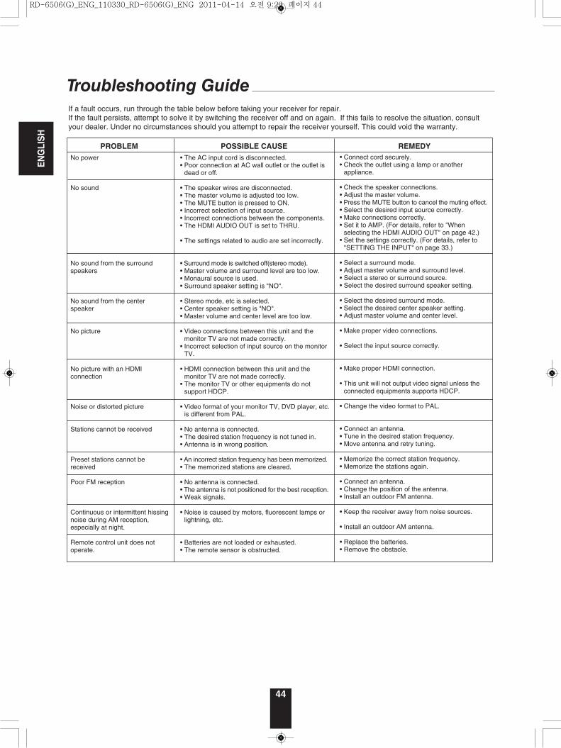
Troubleshooting GuideIf a fault occurs, run through the table below before taking your receiver for repair.If the fault persists, attempt to solve it by switching the receiver off and on again. If this fails to resolve the situation, consultyour dealer. Under no circumstances should you attempt to repair the receiver yourself. This could void the warranty.
ENGLISH
PROBLEM POSSIBLE CAUSE REMEDYNo power
No sound
No sound from the surroundspeakers
No sound from the centerspeaker
No picture
No picture with an HDMIconnection
Noise or distorted picture
Stations cannot be received
Preset stations cannot bereceived
Poor FM reception
Continuous or intermittent hissingnoise during AM reception,especially at night.
Remote control unit does notoperate.
• The AC input cord is disconnected.• Poor connection at AC wall outlet or the outlet is
dead or off.
• The speaker wires are disconnected.• The master volume is adjusted too low.• The MUTE button is pressed to ON.• Incorrect selection of input source.• Incorrect connections between the components.• The HDMI AUDIO OUT is set to THRU.
• The settings related to audio are set incorrectly.
• Surround mode is switched off(stereo mode).• Master volume and surround level are too low.• Monaural source is used.• Surround speaker setting is "NO".
• Stereo mode, etc is selected.• Center speaker setting is "NO".• Master volume and center level are too low.
• Video connections between this unit and themonitor TV are not made correctly.
• Incorrect selection of input source on the monitorTV.
• HDMI connection between this unit and themonitor TV are not made correctly.
• The monitor TV or other equipments do notsupport HDCP.
• Video format of your monitor TV, DVD player, etc.is different from PAL.
• No antenna is connected.• The desired station frequency is not tuned in.• Antenna is in wrong position.
• An incorrect station frequency has been memorized.• The memorized stations are cleared.
• No antenna is connected.• The antenna is not positioned for the best reception.• Weak signals.
• Noise is caused by motors, fluorescent lamps orlightning, etc.
• Batteries are not loaded or exhausted.• The remote sensor is obstructed.
• Connect cord securely.• Check the outlet using a lamp or another
appliance.
• Check the speaker connections.• Adjust the master volume.• Press the MUTE button to cancel the muting effect.• Select the desired input source correctly.• Make connections correctly.• Set it to AMP. (For details, refer to "When
selecting the HDMI AUDIO OUT" on page 42.)• Set the settings correctly. (For details, refer to
"SETTING THE INPUT" on page 33.)
• Select a surround mode.• Adjust master volume and surround level.• Select a stereo or surround source.• Select the desired surround speaker setting.
• Select the desired surround mode.• Select the desired center speaker setting.• Adjust master volume and center level.
• Make proper video connections.
• Select the input source correctly.
• Make proper HDMI connection.
• This unit will not output video signal unless theconnected equipments supports HDCP.
• Change the video format to PAL.
• Connect an antenna.• Tune in the desired station frequency.• Move antenna and retry tuning.
• Memorize the correct station frequency.• Memorize the stations again.
• Connect an antenna.• Change the position of the antenna.• Install an outdoor FM antenna.
• Keep the receiver away from noise sources.
• Install an outdoor AM antenna.
• Replace the batteries.• Remove the obstacle.
RD-6506(G)_ENG_110330_RD-6506(G)_ENG 2011-04-14 오전 9:29 페이지 44
45
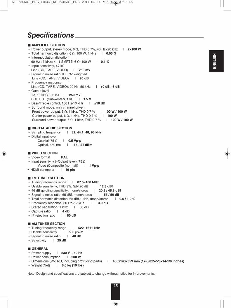
Specifications■ AMPLIFIER SECTION• Power output, stereo mode, 6 Ω, THD 0.7%, 40 Hz~20 kHz | 2x100 W• Total harmonic distortion, 6 Ω, 100 W, 1 kHz | 0.05 %• Intermodulation distortion
60 Hz : 7 kHz= 4 : 1 SMPTE, 6 Ω, 100 W | 0.1 %• Input sensitivity, 47 kΩ
Line (CD, TAPE, VIDEO) | 250 mV• Signal to noise ratio, IHF “A” weighted
Line (CD, TAPE, VIDEO) | 95 dB• Frequency response
Line (CD, TAPE, VIDEO), 20 Hz~50 kHz | +0 dB, -3 dB• Output level
TAPE REC, 2.2 kΩ | 250 mVPRE OUT (Subwoofer), 1 kΩ | 1.5 V
• Bass/Treble control, 100 Hz/10 kHz | ±10 dB• Surround mode, only channel driven
Front power output, 6 Ω, 1 kHz, THD 0.7 % | 100 W / 100 WCenter power output, 6 Ω, 1 kHz, THD 0.7 % | 100 WSurround power output, 6 Ω, 1 kHz, THD 0.7 % | 100 W / 100 W
■ DIGITAL AUDIO SECTION• Sampling frequency | 32, 44.1, 48, 96 kHz• Digital input level
Coaxial, 75 Ω | 0.5 Vp-pOptical, 660 nm | -15~-21 dBm
■ VIDEO SECTION• Video format | PAL• Input sensitivity (=Output level), 75 Ω
Video (Composite (normal)) | 1 Vp-p• HDMI connector | 19 pin
■ FM TUNER SECTION• Tuning frequency range | 87.5~108 MHz• Usable sensitivity, THD 3%, S/N 26 dB | 12.8 dBf• 46 dB quieting sensitivity, mono/stereo | 20.2 / 45.3 dBf• Signal to noise ratio, 65 dBf, mono/stereo | 55 / 50 dB• Total harmonic distortion, 65 dBf,1 kHz, mono/stereo | 0.5 / 1.0 %• Frequency response, 30 Hz~12 kHz | ±3.0 dB• Stereo separation, 1 kHz | 30 dB• Capture ratio | 4 dB• IF rejection ratio | 80 dB
■ AM TUNER SECTION• Tuning frequency range | 522~1611 kHz• Usable sensitivity | 500 µV/m• Signal to noise ratio | 40 dB• Selectivity | 25 dB
■ GENERAL• Power supply | 230 V ~ 50 Hz• Power consumption | 200 W• Dimensions (WxHxD, including protruding parts) | 435x143x359 mm (17-3/8x5-5/8x14-1/8 inches)• Weight (Net) | 8.6 kg (19 lbs)
Note: Design and specifications are subject to change without notice for improvements.
ENGLISH
RD-6506(G)_ENG_110330_RD-6506(G)_ENG 2011-04-14 오전 9:29 페이지 45
RD-6506
5707-00000-573-0S
AUDIO/VIDEO RECEIVERAUDIO/VIDEO RECEIVER
RECEPTOR DE AUDIO/VIDEO
RECEPTEUR AUDIO/VIDEO
АУДИО/ВИДЕО ПРИЕМНИК
6505(G) cover_5lan_cover.qxp 2011-04-14 오전 9:43 페이지 2