90+ Four Position Furnaces N9MP1, N9MP2, *9MPD, … Four Position Furnaces N9MP1, N9MP2, *9MPD,...
12
Fire or explosion hazard. Information in this manual MUST be followed exactly. Failure to follow the information in this manual exactly could result in death, bodily injury and/or property damage. -- -- Do not store or use gasoline or other flammable vapors and liquids in the vi- cinity of this or any other appliance. -- -- WHAT TO DO IF YOU SMELL GAS Do NOT try to light any appliance. Do NOT touch any electrical switch; do NOT use any phone in your building. Immediately evacuate the building and call your gas supplier from a phone outside the building. Follow the gas supplier’s instruc- tions. If you cannot reach your gas supplier, call the fire department. -- -- Installation and service must be performed by a qualified installer, service agency or the gas supplier. Printed in U.S.A. LP1 (6/1/2002) 441 02 2001 07 Manufactured by: International Comfort Products Corporation (USA) Lewisburg, TN USA 37091 ! 90+ Four Position Furnaces N9MP1, N9MP2, *9MPD, *9MPT & *9MPV 80+ Single Stage Furnaces 80+ 2--Stage & Variable Speed Furnaces
Transcript of 90+ Four Position Furnaces N9MP1, N9MP2, *9MPD, … Four Position Furnaces N9MP1, N9MP2, *9MPD,...
Fire or explosion hazard.
Information in this manual MUST befollowed exactly.
Failure to follow the information inthis manual exactly could result indeath, bodily injury and/or propertydamage.
-- -- Do not store or use gasoline or otherflammable vapors and liquids in the vi-cinity of this or any other appliance.
-- -- WHAT TO DO IF YOU SMELL GAS� Do NOT try to light any appliance.� Do NOT touch any electrical switch; do NOT
use any phone in your building.� Immediately evacuate the building and call
your gas supplier from a phone outside thebuilding. Follow the gas supplier’s instruc-tions.
� If you cannot reach your gas supplier, call thefire department.
-- -- Installation and service must be performed byaqualified installer, service agency or the gassupplier.
Printed in U.S.A. LP1 (6/1/2002) 441 02 2001 07
Manufactured by:
International Comfort Products Corporation (USA)Lewisburg, TN USA 37091
!
90+ Four Position FurnacesN9MP1, N9MP2, *9MPD, *9MPT & *9MPV
80+ Single Stage Furnaces80+ 2--Stage & Variable Speed Furnaces
User’s Information Manual
2441 02 2001 07
ContentsDanger, Warning and Caution 2. . . . . . . . . . . . . . . .Safety Rules 3. . . . . . . . . . . . . . . . . . . . . . . . . . . . .Combustion Air (Your safety) 4. . . . . . . . . . . . . . . .
Operating Your Unit 5. . . . . . . . . . . . . . . . . . . . . . . .Unit Maintenance 6. . . . . . . . . . . . . . . . . . . . . . . . .Warranty 11. . . . . . . . . . . . . . . . . . . . . . . . . . . . . . .
Danger, Warning and CautionThe signal words DANGER, WARNING and CAUTION are usedto identify levels of hazardseriousness. Thesignal word DANGERis only used on product labels to signify an immediate hazard. Thesignal words WARNING and CAUTION will be used on product la-bels and throughout this manual andother manuals that may applyto the product.
Signal WordsDANGER -- Immediate hazards which WILL result in severe per-sonal injury or death.
WARNING -- Hazards or unsafe practices which COULD result insevere personal injury or death.
CAUTION -- Hazards or unsafe practices which COULD result inminor personal injury or product or property damage.
Signal Words in ManualsThe signal word WARNING is used throughout this manual in thefollowing manner:
WARNING
The signal word CAUTION is used throughout this manual in thefollowing manner:
CAUTION
Product LabelingSignal words are used in combination with colors and/or pictureson product labels. Following are examples of product labels withexplanations of the colors used.
Danger LabelWhite lettering on a black background except the word DANGERwhich is white with a red background.
DANGER!Electric Shock Hazard
Turn off all powerbefore servicing.
Failure to observe couldresult in death, bodily injuryand/or property damage.
Warning LabelWhite lettering on a black background except the word WARNINGwhich is black with an orange background.
WARNING!Fire Hazard.
Use copper wire only.
Failure to observe couldresult in death, bodily injuryand/or property damage.
Caution LabelWhite lettering on a black background except the word CAUTIONwhich is black with a yellow background.
DANGERCAUTION!Cuts and Abrasion Hazard.
Wear gloves and handle withcare.
Failure to observe couldresult in bodily injury.
User’s Information Manual
3441 02 2001 07
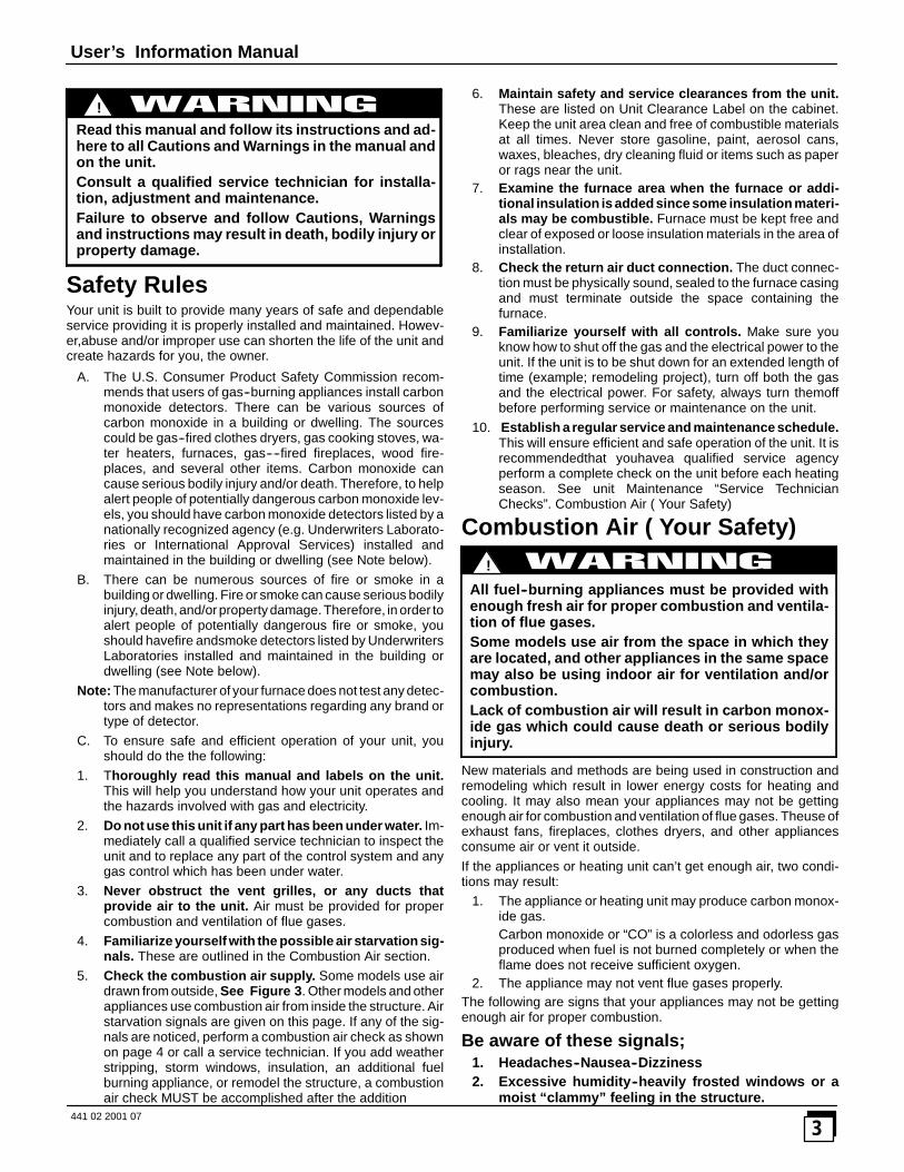
Read this manual and follow its instructions and ad-here to all Cautions and Warnings in the manual andon the unit.Consult a qualified service technician for installa-tion, adjustment and maintenance.Failure to observe and follow Cautions, Warningsand instructions may result in death, bodily injury orproperty damage.
!
Safety RulesYour unit is built to provide many years of safe and dependableservice providing it is properly installed and maintained. Howev-er,abuse and/or improper use can shorten the life of the unit andcreate hazards for you, the owner.
A. The U.S. Consumer Product Safety Commission recom-mends that users of gas--burning appliances install carbonmonoxide detectors. There can be various sources ofcarbon monoxide in a building or dwelling. The sourcescould be gas--fired clothes dryers, gas cooking stoves, wa-ter heaters, furnaces, gas----fired fireplaces, wood fire-places, and several other items. Carbon monoxide cancause serious bodily injury and/or death. Therefore, to helpalert people of potentially dangerous carbon monoxide lev-els, you should have carbon monoxide detectors listed by anationally recognized agency (e.g. Underwriters Laborato-ries or International Approval Services) installed andmaintained in the building or dwelling (see Note below).
B. There can be numerous sources of fire or smoke in abuilding or dwelling. Fire or smoke can cause serious bodilyinjury,death,and/orproperty damage.Therefore, in order toalert people of potentially dangerous fire or smoke, youshould havefire andsmoke detectors listed by UnderwritersLaboratories installed and maintained in the building ordwelling (see Note below).
Note: The manufacturer of your furnace does not test any detec-tors and makes no representations regarding any brand ortype of detector.
C. To ensure safe and efficient operation of your unit, youshould do the the following:
1. Thoroughly read this manual and labels on the unit.This will help you understand how your unit operates andthe hazards involved with gas and electricity.
2. Do not use this unit if any part has been under water. Im-mediately call a qualified service technician to inspect theunit and to replace any part of the control system and anygas control which has been under water.
3. Never obstruct the vent grilles, or any ducts thatprovide air to the unit. Air must be provided for propercombustion and ventilation of flue gases.
4. Familiarize yourself with the possible air starvation sig-nals. These are outlined in the Combustion Air section.
5. Check the combustion air supply. Some models use airdrawn from outside, See Figure 3. Other models and otherappliances use combustion air from inside the structure. Airstarvation signals are given on this page. If any of the sig-nals are noticed, perform a combustion air check as shownon page 4 or call a service technician. If you add weatherstripping, storm windows, insulation, an additional fuelburning appliance, or remodel the structure, a combustionair check MUST be accomplished after the addition
6. Maintain safety and service clearances from the unit.These are listed on Unit Clearance Label on the cabinet.Keep the unit area clean and free of combustible materialsat all times. Never store gasoline, paint, aerosol cans,waxes, bleaches, dry cleaning fluid or items such as paperor rags near the unit.
7. Examine the furnace area when the furnace or addi-tional insulation is added since some insulation materi-als may be combustible. Furnace must be kept free andclear of exposed or loose insulation materials in the area ofinstallation.
8. Check the return air duct connection. The duct connec-tion must be physically sound, sealed to the furnace casingand must terminate outside the space containing thefurnace.
9. Familiarize yourself with all controls. Make sure youknow how to shut off the gas and the electrical power to theunit. If the unit is to be shut down for an extended length oftime (example; remodeling project), turn off both the gasand the electrical power. For safety, always turn themoffbefore performing service or maintenance on the unit.
10. Establish a regular service and maintenance schedule.This will ensure efficient and safe operation of the unit. It isrecommendedthat youhavea qualified service agencyperform a complete check on the unit before each heatingseason. See unit Maintenance “Service TechnicianChecks”. Combustion Air ( Your Safety)
Combustion Air ( Your Safety)
All fuel--burning appliances must be provided withenough fresh air for proper combustion and ventila-tion of flue gases.Some models use air from the space in which theyare located, and other appliances in the same spacemay also be using indoor air for ventilation and/orcombustion.Lack of combustion air will result in carbon monox-ide gas which could cause death or serious bodilyinjury.
!
New materials and methods are being used in construction andremodeling which result in lower energy costs for heating andcooling. It may also mean your appliances may not be gettingenough air for combustion and ventilation of flue gases. Theuse ofexhaust fans, fireplaces, clothes dryers, and other appliancesconsume air or vent it outside.If the appliances or heating unit can’t get enough air, two condi-tions may result:
1. The appliance or heating unit may produce carbon monox-ide gas.Carbon monoxide or “CO” is a colorless and odorless gasproduced when fuel is not burned completely or when theflame does not receive sufficient oxygen.
2. The appliance may not vent flue gases properly.The following are signs that your appliances may not be gettingenough air for proper combustion.
Be aware of these signals;1. Headaches--Nausea--Dizziness2. Excessive humidity--heavily frosted windows or a
moist “clammy” feeling in the structure.

User’s Information Manual
4441 02 2001 07
3. Smoke from the fireplace won’t draw up thechimney.
If you experience headaches, nausea, or dizziness,carbon monoxide may be present.Leave the house immediately and call your gas sup-plier.Carbon monoxide poisoning can result in deathfrom asphyxiation or serious bodily injury.
!
Combustion Air ChecksIf any of the signals are noticed, perform a combustion air check orcall a service technician. If you add weather stripping, storm win-dows, insulation, an additional fuel burning appliance, or remodelthe structure, a combustion air check MUST be accomplished af-ter the addition.
Make the inspection as follows:1. Close all doors and windows. If you have a fireplace, start a
fire and wait until flames are burning vigorously.2. Turn on all exhausting devices, such as: kitchen and bath-
room exhaust fans and dryers (gas or electric).3. Turn on all vented gas appliances, such as: heating equip-
ment (includes any room heaters) and water heaters.4. Wait ten (10) minutes for drafts to stabilize.5. On appliances with a draft hood, check for spillage by hold-
ing a lighted match 2 inches from the draft hood opening.Reference Figure 1 which shows a water heater drafthood.
Typical GasWater Heater
Draft HoodVent Pipe
Match
Water Heater Draft HoodFigure 1
A. Match flame pulls toward draft hood.This indicates no spillage and that appliance is gettingenough air for combustion. Return exhausting devices andappliances to the condition you found them .
B. Match goes out or flame wavers away from draft hood. Thisindicates spillage and that appliance is not getting enoughair for combustion.
Draft hood spillage means there is not enough airfor proper combustion and carbon monoxide maybe present.Keep a window open (a minimum of 2���� ) near the ap-pliance until a permanent air duct is installed. Con-tact a qualified service agency.Carbon monoxide poisoning can result in deathfrom asphyxiation or serious bodily injury.
!
If draft hood spillage is indicated:1. Check for plugged flue connectors and chimneys. Repair
stoppage and test again.2. If you have a fireplace, open a window or door near the fire-
place and then check for spillage. If spillage stops, do notuse the fireplace until you can supply fresh air by a perma-nent duct.
3. If you have kitchen and bathroom exhaust fans, turn themOFF and check for spillage.If spillage stops, do not use exhaust fans until you can sup-ply fresh air by a permanent duct. Circuit breakers for fansshould be turned off.
4. Spillage means air starvation and a fresh air duct or air in-takes must be installed to provide air directly to the areaaround the unit. These MUST comply with local and statebuilding codes or in their absence with the National FuelGas Code NFPA 54 ANSI Z223.1, current edition or in Can-ada the National Standard CAN/CGA 1--B149.
Indoor Humidity (Your Comfort)Relativehumidity is important toyourhealth.Properhumidificationhelps cut down incidences of respiratory illness. Air that is too wetmay damage the building structure. Air that is too dry is uncomfort-able. A quick way to test for proper humidity is as follows:
1. Look for frequent fogging or excessive condensation on theinside of windows. This indicates the indoorhumidity level istoo high for outdoor weather conditions.
2. Drop three ice cubes into a glass of water and stir. If, withinthree minutes, moisture does not form on the glass, the air istoo dry and ahumidifier wouldbe beneficial. (Do notperformthis test in the kitchen, cooking vapors may produce inaccu-rate results.)
A good relative humidity is one just highenough tobarely start con-densation along the lower edges or lower corners of the windows,when it is cold outside. More than that can be damaging.
If thehumidity is too high, try thesesuggestions to lower thehumid-ity:
1. Reduce setting or discontinue use of humidifier.2. Use range and bathroom exhaust fans while cooking and
bathing. Open a door or window for a few minutes to bring incool drier air.
3. Cook with pans covered.4. Take shorter baths or showers with cooler water.5. Install a fresh air intake duct. Cold, dry air brought in from
outside to the unit area lowers the indoor humidity level.6. Have appliances checked. A malfunctioning appliance can
contribute water vapor to the structure.7. If the problem continues, consult a heating contractor about
adding a heat recovery ventilator or air to air heat exchang-er.
About Your UnitFigure 2 shows the location of the components in the unit.
Circulating Air BlowerThe blower circulates room air through the unit, air ducts, and intothe rooms of the structure. The blower can be set at the thermostatfor automatic or manual operation. In manual mode the blower op-erates continuously. In automatic, the blower does not come onuntil a preset time after the gas valve is energized. When the struc-ture reaches the temperature set on the thermostat, the unit willshut off. The blower will continue to run until the unit cools down.
User’s Information Manual
5441 02 2001 07
ThermostatThere are many types and styles of thermostats. Most thermostatscontrol both heating and cooling functions and have a Fan Switchwith AUTO and ON settings. On AUTO, the Circulating Air Blowerwill cycle on/off with the unit, on the heating speed unless a call forcooling is initiated. Blower speed will correspond to the mode ofoperation of the unit. If the Fan Switch is positioned to ON theblow-er will run continuously.
In addition some thermostats are programmable with multiple setbacks. The set backs canbe pre--programmed to loweror raise thetemperature automatically.
Be sure to become familiar with your thermostat.
Rating PlateThe rating plate contains important information for the servicetechnician and lists the complete model, manufacturing and serialnumbers. You should always provide all these numbers when re-questing parts or if you need service. See Figure 2 or Figure 3for rating plate location.
Door Interlock SwitchAll the electrical power for the unit goes through the door interlockswitch. The interlock switch interrupts electrical power to the unitwhen the blower door is removed. The unit will not operate until theblower door is reinstalled.
Fan ControlThe fan/delay control provides power to the circulating air blowerto keep it on until the unit cools down.
The fan off setting can be adjusted if the fan remains on longenough that cool drafts are felt in the room after the furnace shutsoff.
The delay is set by moving a set of switches on the control. TheWiring Diagram located on the inside of the blower door shows thevarious delay combinations. Refer to Figure 2 or Figure 3 forlocation of the control.
If you are unsure how to set the Fan Control, contact a QualifiedService Technician.
Electronic Ignition Module/Gas ValveWhen the thermostat calls for heat it completes a circuit to theelec-tronic ignition module. The module sends an electrical signalwhich ignites the pilot, then opens the gas valve.
When the flame is firmly established the ignitor goes off. If there isa malfunction, the gas valve automatically shuts off the gas.
Pressure SwitchThe unit is equipped with two pressure switches to shut down theunit under various flue conditions. The switches are connected tothe furnace by factory supplied tubing.
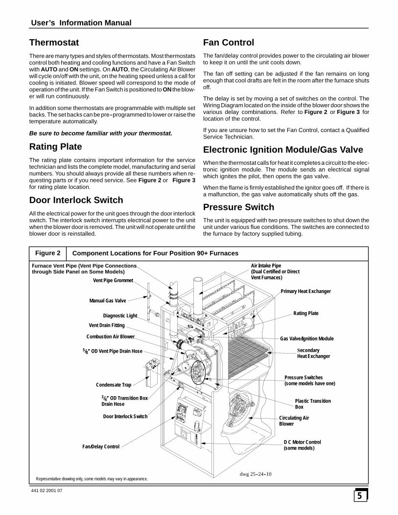
Component Locations for Four Position 90+ Furnaces
Primary Heat Exchanger
Circulating AirBlower
Figure 2
Fan/Delay Control
Pressure Switches(some models have one)
Representative drawing only, some models may vary in appearance.dwg 25--24--10
Air Intake Pipe(Dual Certified or DirectVent Furnaces)
Rating Plate
SecondaryHeat Exchanger
Gas Valve/Ignition Module
Plastic TransitionBox
D C Motor Control(some models)
Door Interlock Switch
Condensate Trap
3/4���� OD Transition BoxDrain Hose
5/8���� OD Vent Pipe Drain Hose
Combustion Air Blower
Vent Drain Fitting
Vent Pipe Grommet
Manual Gas Valve
Furnace Vent Pipe (Vent Pipe Connectionsthrough Side Panel on Some Models)
Diagnostic Light
User’s Information Manual
6441 02 2001 07
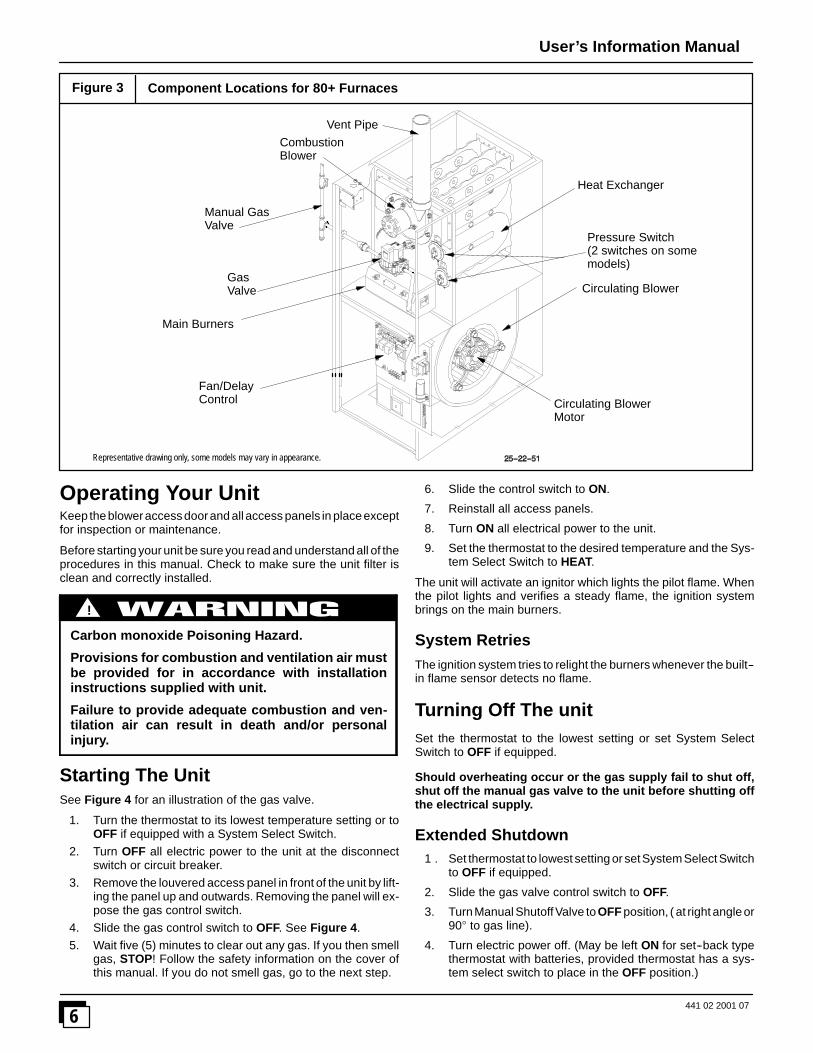
Component Locations for 80+ Furnaces
GasValve
Main Burners
Circulating BlowerMotor
Heat Exchanger
CombustionBlower
Circulating Blower
Figure 3
Fan/DelayControl
Manual GasValve
Pressure Switch(2 switches on somemodels)
Vent Pipe
Representative drawing only, some models may vary in appearance.
Operating Your UnitKeep thebloweraccess doorand all access panels in placeexceptfor inspection or maintenance.
Before starting your unit be sure you read and understand all of theprocedures in this manual. Check to make sure the unit filter isclean and correctly installed.
Carbon monoxide Poisoning Hazard.
Provisions for combustion and ventilation air mustbe provided for in accordance with installationinstructions supplied with unit.
Failure to provide adequate combustion and ven-tilation air can result in death and/or personalinjury.
!
Starting The UnitSee Figure 4 for an illustration of the gas valve.
1. Turn the thermostat to its lowest temperature setting or toOFF if equipped with a System Select Switch.
2. Turn OFF all electric power to the unit at the disconnectswitch or circuit breaker.
3. Remove the louvered access panel in front of the unit by lift-ing the panel up and outwards. Removing the panel will ex-pose the gas control switch.
4. Slide the gas control switch to OFF. See Figure 4.5. Wait five (5) minutes to clear out any gas. If you then smell
gas, STOP! Follow the safety information on the cover ofthis manual. If you do not smell gas, go to the next step.
6. Slide the control switch to ON.
7. Reinstall all access panels.
8. Turn ON all electrical power to the unit.
9. Set the thermostat to the desired temperature and the Sys-tem Select Switch to HEAT.
The unit will activate an ignitor which lights the pilot flame. Whenthe pilot lights and verifies a steady flame, the ignition systembrings on the main burners.
System RetriesThe ignition system tries to relight the burners whenever the built--in flame sensor detects no flame.
Turning Off The unitSet the thermostat to the lowest setting or set System SelectSwitch to OFF if equipped.
Should overheating occur or the gas supply fail to shut off,shut off the manual gas valve to the unit before shutting offthe electrical supply.
Extended Shutdown1 . Set thermostat to lowest setting or setSystem SelectSwitch
to OFF if equipped.
2. Slide the gas valve control switch to OFF.
3. TurnManual ShutoffValve toOFF position, ( at right angleor90� to gas line).
4. Turn electric power off. (May be left ON for set--back typethermostat with batteries, provided thermostat has a sys-tem select switch to place in the OFF position.)

User’s Information Manual
7441 02 2001 07
25--22--25a
Typical Gas Valve HoneywellGas FurnacesFigure 4
INLET
OUTLET
Manifold Adjustment(Hidden) Diagnostic
Light(on some models)
On/OffSwitch
Pilot Adjustment(Hidden) on somemodels
Typical Gas Valve Honeywell 80+ Furnaces
Single Stage (90+ Furnaces)
dwg 25--23--31a
INLET
Manifold PressureAdjustment
Pilot PressureAdjustment (Hidden)
On\OffSwitch
Diagnostic Light
OUTLET
INLET
OUTLET
Manifold PressureAdjustment
LO HI
25--22--49a
Two Stage (90+ Furnaces)
L P Model UnitsIf your L.P. (liquefied petroleum) gas unit is installed in an exca-vated or low lying area, we recommend that you contact your L.P.supplier about installing a warning device that would alert you of agas leak.
Fire or explosion hazard.L.P. gas is heavier than air. Leaking gas can settle inlow areas such as a crawl space. If you suspect thepresence of gas, follow the instructions on the cov-er of this manual.Failure to observe could result in death, bodily inju-ry or property damage.
!
Freezing Temperatures And Your Structure
Freeze warning.Turn off water system.If your unit remains shut off during cold weatherthe water pipes could freeze and burst, resulting inserious water damage.
!
Your unit is equipped with safety devices that may keep it from op-erating if sensors detect abnormal conditions such as clogged ex-haust flues.
If your unit remains shut off during cold weather the water pipescould freeze and burst, resulting in serious water damage.
If the structure will be unattended during cold weather you shouldtake these precautions.
1. Turn off main supply water into the structure and drain thewater lines if possible. Open faucets in appropriate areas.
2. Have someone check the structure frequently during coldweather to make sure it is warm enough to prevent pipesfrom freezing. Suggest they call qualified service agency, ifrequired.
Winter Shutdown (90+ Furnaces)1. Disconnect the 5/8� OD rubber hose from the vent drain
fitting that is located downstream of the combustion blower.Insert a funnelintothehose andpourfour(4)ounces ofsani-tary type (RV) antifreeze into the condensate trap. Re-connect the 5/8� OD rubber hose to the stub on the ventdrain fitting. Secure with the hose clamp.
2. Disconnect the 3/4� OD rubber hose from the condensatetrap. Insert a funnel into the hose and and pour four(4)ounces of sanitary type (RV) antifreeze into the plastic tran-sition box. Squeeze the hose together near the end andquickly reconnect the 3/4�OD rubber hose to the stub on thecondensate trap. Secure with the hose clamp.
When you return home, your furnace will be ready to start, as it isnot necessary to drain the antifreeze from the furnace.
Unit MaintenanceHave your unit inspected and serviced on an annual basis (beforethe heating season) by a qualified service technician.
User’s Information Manual
8441 02 2001 07
Labeling
CAUTIONLabel all wires prior to disconnection when servicingcontrols. Wiring errors can cause improper and dan-gerous operation.
Verify proper operation after servicing.
Pressure SwitchesDuring regular yearly maintenance check for cracks in anytubes on the pressure switches.
Electric shock hazard.Turn off electrical power to unit before performingany maintenance or removing panels or doors.Failure to observe could result in death or bodilyinjury.
!
Air Filters/ MonthlyThe air filter(s) should be inspected at least monthly andcleaned or replaced as required. There are two types of filtersthat are commonly used. The most widely used is the Fiber-glass disposable type which should be REPLACED before itbecomes clogged. The other type is the washable typeconstructed of aluminum mesh, foam, or reinforced fibers.Washable filters may be cleaned by soaking in mild detergentand rinsing with water.
Remember that dirty filters are the most common cause of in-adequate heating or cooling performance.
Fire hazard from dust and lint buildup on internalunit parts.Never operate unit without a filter installed.Failure to observe could result in death or bodilyinjury.
!
Replacement FiltersTable 1 lists recommended sizes and types of filters that may beused with your unit, based on the input rating and Btuh.
Replacement filters should be of the same type and size as theoriginals, to ensure adequate air flow and filtering. A disposablelow velocity filter can be replaced with a washable high velocitytype. Do not replace a high velocity filter with a disposable low ve-locity filter.
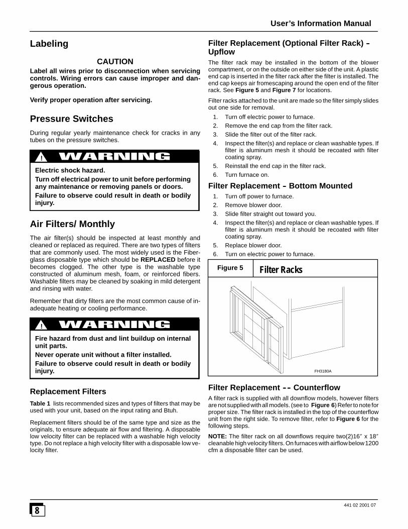
Filter Replacement (Optional Filter Rack) --UpflowThe filter rack may be installed in the bottom of the blowercompartment, or on the outside on either side of the unit. A plasticend cap is inserted in the filter rack after the filter is installed. Theend cap keeps air fromescaping around the open end of the filterrack. See Figure 5 and Figure 7 for locations.
Filter racks attached to the unit are made so the filter simply slidesout one side for removal.
1. Turn off electric power to furnace.2. Remove the end cap from the filter rack.3. Slide the filter out of the filter rack.4. Inspect the filter(s) and replace or clean washable types. If
filter is aluminum mesh it should be recoated with filtercoating spray.
5. Reinstall the end cap in the filter rack.6. Turn furnace on.
Filter Replacement -- Bottom Mounted1. Turn off power to furnace.2. Remove blower door.3. Slide filter straight out toward you.4. Inspect the filter(s) and replace or clean washable types. If
filter is aluminum mesh it should be recoated with filtercoating spray.
5. Replace blower door.6. Turn on electric power to furnace.
Filter RacksFigure 5
FH3180A
Filter Replacement -- -- CounterflowA filter rack is supplied with all downflow models, however filtersare notsupplied withall models. (see to Figure 6) Refer to note forproper size. The filter rack is installed in the top of the counterflowunit from the right side. To remove filter, refer to Figure 6 for thefollowing steps.
NOTE: The filter rack on all downflows require two(2)16� x 18�cleanable high velocity filters. On furnaces with airflow below1200cfm a disposable filter can be used.
User’s Information Manual
9441 02 2001 07
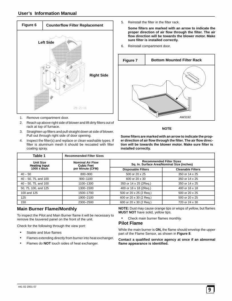
Counterflow Filter Replacement
Right Side
Left Side
Figure 6
1. Remove compartment door.2. Reach up above right side of blower and lift dirty filters out of
rack at top of furnace.3. Straighten up filters and pull straight down at side of blower.
Pull out through right side of door opening.4. Inspect the filter(s) and replace or clean washable types. If
filter is aluminum mesh it should be recoated with filtercoating spray.
5. Reinstall the filter in the filter rack.
Some filters are marked with an arrow to indicate theproper direction of air flow through the filter. The airflow direction will be towards the blower motor. Makesure filter is installed correctly.
6. Reinstall compartment door.
Bottom Mounted Filter RackFigure 7
AW3192
NOTE
Some filters are marked with an arrow to indicate the prop-er direction of air flow through the filter. The air flow direc-tion will be towards the blower motor. Make sure filter isinstalled correctly.
Table 1 Recommended Filter Sizes
Unit SizeHeating Input
Nominal Air FlowCubic Feet
Recommended Filter SizesSq. In. Surface Area/Nominal Size (inches)Heating Input
1000 x BtuhCubic Feet
per Minute (CFM) Disposable Filters Cleanable Filters
40 -- 50 800--900 500 or 20 x 25 350 or 14 x 25
40 -- 50, 75, and 100 900--1100 600 or 20 x 30 350 or 14 x 25
40 -- 50, 75, and 100 1100--1300 350 or 14 x 25 (2Req.) 350 or 14 x 25
50, 75, 100, and 125 1300--1500 400 or 16 x 18 (2Req.) 400 or 16 x 18
100 and 125 1500--1700 500 or 20 x 25 (2 Req.) 500 or 20 x 25
125 1900--2100 600 or 20 x 30 (2 Req.) 500 or 20 x 25
150 2300--2500 600 or 20 x 30 (2 Req.) 720 or 24 x 30
Main Burner Flame/MonthlyTo inspect the Pilot and Main Burner flame it will be necessary toremove the louvered panel on the front of the unit.
Check for the following through the view port:
� Stable and blue flames
� Flames extending directly from burner into heat exchanger.
� Flames do NOT touch sides of heat exchanger.
NOTE: Dust may cause orange tips or wisps of yellow, but flamesMUST NOT have solid, yellow tips.
� Check main burner flames monthly.Pilot FlameWhile the main burner is ON, the flame should envelop the upperpart of the Flame Sensor, as shown in Figure 8.
Contact a qualified service agency at once if an abnormalflame appearance is identified.

User’s Information Manual
10441 02 2001 07
Pilot BurnerFigure 8
Proper FlameAdjustment
Flame Sensor
Hot SurfaceIgniter
10--11--65
3/8���� to 1/2����
Flame SensorPilot Burner
Monthly InspectionA properly adjusted gas unit should not require cleaning at fre-quent intervals, but it should be inspected regularly to ensure safeand efficient operation. A brief monthly inspection is recom-mended that does not require disassembly. In addition you shouldhave the unit inspected, and cleaned if required, by a qualified ser-vice technician annually.
1. Check the vents to be sure they are clear and free of ob-structions.
2. Check return air duct to make sure it is sealed to unit casingand that it is in good physical condition.
3. Inspect the unit base. It must be in good physical condition.
4. Inspect the drain line and overflow line monthly.
5. Remove the front panel and use a flashlight to inspect thevisible part of the burners and igniter. Check for loose sootand give particular attention to obvious deterioration fromcorrosion or other sources. If soot or deterioration is foundinside the unit DO NOT OPERATE UNIT; call a qualified ser-vice technician.
LubricationThe blower motor and the combustion air blower are prelubricatedby the manufacturer and DO NOT require oiling.
Service Technician ChecksWhen the unit is being inspected for condition and operationhave the Service Technician check the following items.
1. Check all flue gas passages including main and pilotburners, heat exchanger, and vent.
2. Check all flue gas passages including main and pilotburners, heat exchanger, and vent .
3. Check electrical wiring and connections.
4. Check supply andreturn air ducts for leakage, blockage andconnections to unit.
5. Check circulating air blower wheel and motor. Clean them ifrequired.
6. Perform an operational checkout on the unit to be suresafety controls function and that unit operates properly.
For additional information, the Service Technician can consult theinstallation instructions for the unit.

INTERNATIONAL COMFORT PRODUCTSLIMITED WARRANTY CERTIFICATE
For Cooling & Heating Products
SAVE THIS CERTIFICATE. It gives you specific legal rights, and you may also have other rights which may vary from state to state andprovince to province.
If your unit needs servicing, contact a qualified dealer or qualified service technician of your choice. When requesting service, please have the modeland serial number from each unit in your heating and/or cooling system readily available. If your dealer needs assistance, the distributor is available toprovide support and we, in turn, support its efforts.
Fill in the installation date and model and serial numbers of the unit in the space provided below and retain this Limited Warranty for your files.
GENERAL TERMS
Subject to the conditions and limitations stated herein, during the term of this Limited Warranty, we will provide a replacement for any functionalcomponent part (as defined below) of your unit found to be defective in materials or workmanship. The term of this Limited Warranty is five years frominstallation on Residential Products and one year from installation on Commercial Products. Except as otherwise stated in the ‘‘Additional Terms’’section, this Limited Warranty covers only the original purchaser and subsequent transferees, and only while the unit remains at the site of the originalinstallation (except for mobile home installations), and only if the unit is installed inside the continental United States, Puerto Rico, Alaska, Hawaii orCanada. In addition, the Limited Warranty applies only if the unit is installed and operated in accordance with the printed instructions accompanying theunit, and in compliance with all applicable installation and building codes and good trade practices. As used in this Limited Warranty, ‘‘installation”means the original installation of the unit.
THERE ARE EXCEPTIONS to this Limited Warranty as described on the reverse side of this page. All replacement parts will be warranted for theunused portion of the warranty coverage period on the unit. The part to be replaced must be returned by the dealer to a distributor that sells products forInternational Comfort Products, in exchange for the replacement part. In lieu of providing a replacement part, we may, at our sole option, refund to youan amount equal to the distributor’s component purchase price fromus, or provide to you a credit equal to that amount to be applied toward the purchaseof any new unit that we distribute. If a credit for a new unit is given in lieu of a replacement part, the rating plate from the unit being replaced must besubmitted on a warranty claim, and your dealer must make the unit being replaced available to our distributor for disposition. As a condition to warrantycoverage, the unit must receive yearly maintenance, as described in the owner’s manual, by a dealer. Satisfactory proof of yearly service by a dealermay be required.‘‘Functional component parts” include only the following: blower motor, unit--mounted sensors & timers, condenser motor, evaporator coil, condensercoil, condenser fan, capacitor, transformer, single--phase strip heat elements, expansion device, reversing valve, solenoid valve, service valve,electronic and electro--mechanical control board, ignitor, ignition module, draft inducer assembly, burner pilot, gas valve, limit control, pressure switch,relays and contactors, blower wheel, interlock switch, crosslighter, pilot shield, gas & oil burners, oil pump assembly, accumulators and factory installeddriers and strainers.
This Limited Warranty DOES NOT COVER any labor, material, refractory chambers, oil nozzles, refrigerant, refrigerant inspection and refrigerantreclaiming, freight and/or handling charges associated with any repair or replacement and such charges will be your responsibility.
To establish the installation date for any purpose under this Limited Warranty, you must retain the original records that can establish the installation dateof your unit. If you do not provide such documents the start date of the term of this Limited Warranty will be based upon the date of unit manufacture, plusthirty (30) days. In establishing that the required yearly service has occurred, you must furnish proof of yearly service by a qualified service technician.
This Limited Warranty does not cover: (a) failure or damages caused by accident, abuse, negligence, misuse, riot, fire, flood, or Acts of God (b)damages caused by operating the unit where there is a corrosive atmosphere containing chlorine, fluorine, or any other damaging chemicals (otherthan those found in a normal residential environment) (c) damages caused by an unauthorized alteration or repair of the unit affecting its stability orperformance (d) damages caused by improper matching or application of the unit or the unit’s components (e) damages caused by failing to provideproper maintenance and service to the unit in accordance with this Limited Warranty Certificate and the printed instructions originally provided with theunit (f) any expenses incurred for erecting, disconnecting, or dismantling the unit (g) parts or supplies used in connection with service or maintenance,such as refrigerant, refractory chambers, oil nozzles, filters, or belts (h) damage, repairs, inoperation or inefficiency resulting from faulty installation orapplication (i) electricity or fuel costs or any increase in electricity or fuel cost whatsoever including additional or unusual use of supplemental electricheat (j) units which have not had the required yearly maintenance described elsewhere in this limited warranty.
In no event shall we be liable for any incidental, consequential, or special damages or expenses in connection with any use or failure of this unit.
We have not made, do not make, and hereby disclaim any implied condition or implied warranty of fitness for a particular use or purpose, andany implied condition or implied warranty of merchantability, to the fullest extent allowed by law. We make no express or implied warrantiesexcept as stated in this Limited Warranty certificate.No one is authorized to change this Limited Warranty or to create for us any other obligation or liability in connection with this unit. Any impliedwarranties shall last for the term of the expressed warranty contained herein. Some states and provinces do not allow the exclusion or limitation ofincidental or consequential damages or do not allow limitations on how long an implied warranty or condition lasts, so the above limitations or exclusionsmay not apply to you. The provisions of this Limited Warranty are in addition to and not a modification of or subtraction from any statutory warranties andother rights and remedies provided by law.
Please refer to reverse side of this page for additional terms.
Model No. _________________________________
Serial No. __________________________________ Date Installed _______________________________
Effective on units installed After July 1, 2002.USA: International Comfort Products Corporation (USA) �650 Heil--Quaker Avenue �P.O. Box 128 �Lewisburg, Tennessee 37091 � (931--270--4100)CANADA: International Comfort Products division of UTC Canada Corporation � 6060 Burnside Court, Unit 1, Mississauga, Ontario L5T 2T5(905--795--8113).Manufacturers of Airquest, Arcoaire, Clare, Comfortmaker, Dettson, Heil, Keeprite, Lincoln, Tempstar and other quality brand name private labelproducts.
Part No. 401 06 1010 17 (Orig. 7/1/2002)
ADDITIONAL TERMS FOR RESIDENTIAL APPLICATIONS ONLYThe Additional Terms for the components listed below are in addition to, and subject to, the General Terms on the reverse side of this page.
Warranty coverage is limited to parts that fail due to defect in materials or workmanship during the specified term.
CENTRAL GAS & OIL FURNACE HEAT EXCHANGERS*Gas Model Series: C9MPV, H9MPV, T9MPV, C9MPT, H9MPT, T9MPT, C9MPD, H9MPD, T9MPD: Limited Lifetime Warranty on heat exchangers. Ifa heat exchanger on one of these furnaces fails due to defect in the part, we will provide a replacement part or, at our option, credit toward the purchaseof a new furnace manufactured by us. This additional Limited Warranty runs only to the original purchaser, and lasts only for as long as the originalpurchaser lives in the home where the furnace is initially installed.** It is not transferable to any subsequent owner. If the furnace was not installed in thehome owned by the original purchaser, if the original purchaser sells the home to a subsequent owner, or if proof of original purchase cannot beprovided, then the limited warranty is only for 20 years from the date of original installation.
Gas Model Series: GDL, GNL, TNE, TDE, NTC7, NDC7, NTP6, NDP6, TDE, NTV6, VNE: A replacement heat exchanger will be provided for anyheat exchanger that fails in one of these furnaces due to defect for 25 years from the original date of installation.
Gas Model Series: NTC6, GNE, GDE, NDN6, NTG3, NDN3, FBF, NBF, NDF, NTN3, NTN6, NNE, N9MP1, N9MP2, FUH: A replacement heatexchanger will be provided for any heat exchanger that fails in one of these furnaces due to defect for 20 years from original date of installation.Oil Model Series: OLR(105, 160, 182), OCF, OLF, OUF, NOLF, NOUF, OLB, OHB, ODH, FLO, MBO, LBO, NOMF: Limited Lifetime Warranty onheat exchangers. If a heat exchanger on one of these furnaces fails due to defect in the part, we will provide a replacement part or, at our option, credittoward the purchase of a new furnace manufactured by us. This additional Limited Warranty runs only to the original purchaser, and lasts only for aslong as the original purchaser lives in the home where the furnace is initially installed.** It is not transferable to any subsequent owner. If the furnacewas not installed in the home of the original purchaser, if the original purchaser sells the home to a subsequent owner, or if proof of original purchasecannot be provided, then the limited warranty is only for 20 years from the date of original installation.
Oil Fired Floor Furnace: NFO: A replacement heat exchanger will be provided for any heat exchanger that fails due to defect for 10 years frominstallation with the following limitation: during the sixth through tenth year, any credit toward your purchase of a component or toward the purchase ofany new unit will be in an amount equal to the distributor’s purchase price reduced by 20 percent for each year after the fifth year.
ADDITIONAL TERMS FOR OIL FURNACE APPLICATIONS ONLY1) OIL BURNERS -- A replacement for 5 years from date of original installation for Oil Burner Parts.2) OPTIONAL ACCESSORIES AND FUNCTIONAL PARTS: A replacement for 5 years from date of original installation. (Refractory andoil nozzles not included)GAS/ELECTRIC PACKAGED UNITS HEAT EXCHANGERSModel series: PGAD, PGAA, PGMD, PGME, PGF, GPFM, PGC, GPCM, PGK, GPK: A replacement for 10 years from original date of installation.
COMPRESSORS:*1) Premium Model Units: HAC0, HAC2, HAC4, CAC0, CAC2, CAC4, KAC0, TCA0, TCA2, TCA4, HHP0, HHP2, HHP4, CHP0, CHP2, CHP4,TCH0, TCH2, TCH4, PGME, PYMC, PGK, GPK, PHAD, PGAD, PA95, PAPC, PAK, APK: To the original purchaser a replacement for 10 years fromoriginal date of installation, only if the unit is installed with factory matched coils, except air conditioner condensing units with a nominal SEER of 10 maybe matched with evaporator coils of the same nominal tonnage regardless of manufacturer and in accordance to factory recommendations. This limited10--year warranty is not transferable to any subsequent owner. HOWEVER, if the unit was not installed in the home owned by the original purchaser, ifthe purchaser sells the home to a subsequent owner, or if proof of original purchase cannot be provided, then the limited warranty is only for 5 years fromthe original date of installation.**
2) All Other Models: Air Conditioners, Heat Pumps, & Combination Gas/Electric Units: NAC0, NAC2, NHP0, NHP2, AO, A2, HO, H2, PGF,PGC, GPFM, GPCM, PAF, APFM, PHF, HPFM, PGAA, PGMD, PA55, PH55, PAPA, PYPA: A replacement for 5 years from date of originalinstallation, only if: (a) air conditioner condensing units with SEER rating in the range of 10 to 11 SEER are matched with evaporator coils of the samenominal tonnage regardless of manufacturer and in accordance to factory recommendations, or (b) heat pump condensing units are used with factorymatched coils, unless written approval to do otherwise is obtained from manufacturer.
ADDITIONAL TERMS FOR COMMERCIAL APPLICATIONS ONLYFor purposes of this warranty a commercial application is one in which: the product has over 5 tons nominal cooling capacity, or is designedfor operation with 3 phase electrical power, or is installed in a commercial establishment such as a beauty or hair salon, hospital, school,restaurant, church, hotel etc..3--Phase Models: PGF, GPFM, GPF, PGAD, PGME, PGB, PGMG, PGMF, PGS, PGE, APE, PAE, PAB, PAMD, PAS, PAF, APFM, APF, PHB, , PHE,PYMD, HPB, PHS, CAC, CAC, CAE, ACE, CHE, HCE:
The additional Terms of the components listed below are in addition to and subject to the General Terms on the reverse side of this page.
1) GAS FIRED HEAT EXCHANGERS (ALL MODELS):* A replacement for 10 years (5 years for PGS Series) from date of original installation.2) COMPRESSORS (ALL MODELS):* A replacement for 5 years from date of original installation. (1 year for PGS/PAS240 and PGE/PAE240 ModelSeries).*3) OPTIONAL ACCESSORIES AND FUNCTIONAL COMPONENT PARTS (ALL MODELS):*A replacement for 1 year from date of original installation.4) COMMERCIAL OIL MODELS: OLR210, OLR350, OTF210, AMT3, AMT4, AMP3: Ten(10) Year Limited Warranty on heat exchangers.*To receive advantage of your limited warranty, you must provide proof of yearly service by a qualified service technician.
**To receive advantage of your warranty, you must retain the original records that can establish the installation date and proof of purchase of the unit.
MINI SPLITS:Summary -- Mini Splits Warranted for one (1) year on all replacement parts.Additional terms for Mini Splits:The additional Terms of the components listed below are in addition to, and subject to, the General Terms on the reverse side of this page.
1) Compressors (All Models): A replacement compressor will be provided for all compressors that fail due to defect for 5 years from date of originalinstallation.
2) Optional Accessories and Functional Components Parts (All Models):A replacement part will be provided for all parts that fail due to defect for one (1) year from date of original installation.
Failure to maintain the equipment through annual maintenance by a qualified service technician shall void the warranty. Proof of service will be requiredwith all warranty claims. Proof of purchase and installation date must be submitted with all claims.