機能安全が可能にする機械の安全確保 - mhlw...機能安全が可能にする機械の安全確保 − 産業用ロボットシステムの安全制御に機能安全を導入するためには
KKKKKKOOOOOOOOMMMMMMMMAAAAAAATTTTTTTTSSSSSSSSUUUUUUUUPPPPPPPP OOOOOOOO WWWWWWWW EEEEEEEE RRRRRRRRRPPPPPPPRRRRRRRREEEEEEEESSSSSSSSSSSSSSSSEEEEEEESSSSSSS
ココココココココマママママママツツツツツツツツ産産産産産産産機機機機機機機
先進の制御
Komatsu Industries Corp.
鍛圧販売本部 営業企画部〒920-0225石川県金沢市大野町新町1-1TEL: 076-293-4209 FAX: 076-293-4354
Sales Planning Department Marketing Division1-1 Ono-machi-shinmachi, Kanazawa-shi Ishikawa 920-0225,JapanPhone:+81-76-293-4209 FAX: +81-76-293-4354
コマツ産機株式会社
●本機をご利用される際の、注意事項の詳細は取扱説明書をご覧下さい。●本仕様は改良のため、予告なく変更することがありますのでご了承下さい。●掲載写真は一部販売機と異なる場合があります。
NETWORK
KOMTRAXは機械情報を遠隔で確認するためのシステムです。機械に装備された通信システムが、稼働情報やアラーム情報を自動的に収集し、専用のデータサーバへ蓄積します。KOMTRAXウェブサイトへアクセスすれば、保有機械の稼働状況をいつでも閲覧する事ができます。
KOMTRAX is the system in which you can check your machines' data remotely.The communication system in a machine gleans its operational data or its alarm data automatically and compiles them in the KOMTRAX data server.You can browse operational status of your machines whenever you access on KOMTRAX website.
Komatsu Industries Corp.
http://www.komatsusanki.co.jp/
The information in this leaflet is subject to change without notice.Actual appearance of a machine may be different from one in photo.
Komatsu Industries Corp.
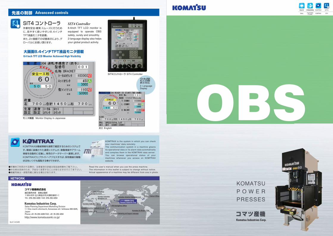
SIT4コントローラ SIT4 Controller
8.4 Inch TFT LCD Monitor Achieved High Visibility
Advanceed controls
大画面8.4インチTFT液晶モニタ搭載
2- Language Display
作業を安全・確実・スムーズに行うために、見やすく使いやすい8.4インチTFT液晶モニタを装備。また、2ヶ国語での切替表示により、グローバルにお使い頂けます。
SIT4コントローラ8.4inch TFT LCD monitor is equipped to operate OBS safety, surely and smoothly.2-language display also helps your global product activity.
SIT4 Controller
英文
モニタ画面
English
Monitor Display in Japanese
コマツ産機株式会社
Komatsu America Industries LLC.
KIS Guangzhou Office
KAILLC Detroit Office
Komatsu India Pvt Ltd.
Komatsu Industries Europe G.m.b.H.
Komatsu Industries (Shanghai) Ltd.
Komatsu Industries (Thailand) Co.,Ltd.
KITH Kuala Lumpur OfficePT Komatsu Marketing and Support Indonesia
Komatsu Do Brasil LTDA.
2カ国表示対応
SLK14-045
安全性 3年間品質保証
A guaranteeof quality
KOMTRAX
KOMTRAX
SIT4
SIT4Safety
4
4
3
OBS
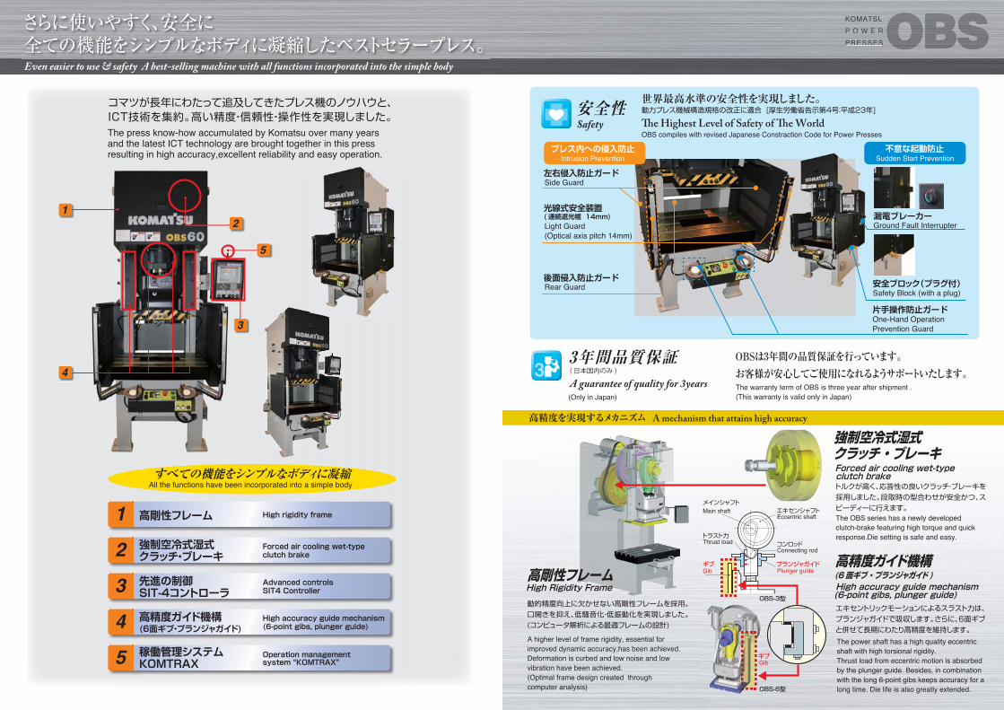
さらに使いやすく、安全に全ての機能をシンプルなボディに凝縮したベストセラープレス。
世界最高水準の安全性を実現しました。安全性
動的精度向上に欠かせない高剛性フレームを採用。口開きを抑え、低騒音化・低振動化を実現しました。(コンピュータ解析による最適フレームの設計)
高剛性フレーム
エキセントリックモーションによるスラスト力は、プランジャガイドで吸収します。さらに、6面ギブと併せて長期にわたり高精度を維持します。
高精度ガイド機構 (6面ギブ・プランジャガイド )
左右侵入防止ガード
安全ブロック(プラグ付)
漏電ブレーカー
後面侵入防止ガード
光線式安全装置(連続遮光幅 14mm)
片手操作防止ガード
プレス内への侵入防止 不意な起動防止
OBSは3年間の品質保証を行っています。お客様が安心してご使用になれるようサポートいたします。3
3年間品質保証
Main shaftEccentric shaft
Connecting rod
Plunger guideGib
Gib
Thrust load
メインシャフトエキセンシャフト
コンロッド
プランジャガイド
トラスト力
ギブ
ギブ
トルクが高く、応答性の良いクラッチ・ブレーキを採用しました。段取時の型合わせが安全かつ、スピーディーに行えます。
強制空冷式湿式 クラッチ・ブレーキ
( 日本国内のみ )
高精度を実現するメカニズム
OBS-3型
OBS-6型
すべての機能をシンプルなボディに凝縮
高剛性フレーム
コマツが長年にわたって追及してきたプレス機のノウハウと、ICT技術を集約。高い精度・信頼性・操作性を実現しました。
KKOMKOMKOMKOMKOMATSATSATSATSATSUUUU
P O WP O WP O WP O WP O WW E RE RE RE RE R
PREREPREPREPRESSESSESSSSESSESSSSS
1強制空冷式湿式クラッチ・ブレーキ2
先進の制御 SIT-4コントローラ3
高精度ガイド機構(6面ギブ・プランジャガイド)4稼働管理システム KOMTRAX5
1
4
3
5
2
Even easier to use & safety A best-selling machine with all functions incorporated into the simple body
High rigidity frame
Forced air cooling wet-type clutch brake
Advanced controlsSIT4 Controller
High accuracy guide mechanism(6-point gibs, plunger guide)
Operation management system “KOMTRAX”
The press know-how accumulated by Komatsu over many years and the latest ICT technology are brought together in this pressresulting in high accuracy,excellent reliability and easy operation.
All the functions have been incorporated into a simple body
The Highest Level of Safety of The World
Sudden Start PreventionIntrusion Prevention
OBS compiles with revised Japanese Constraction Code for Power Presses
Side Guard
Light Guard(Optical axis pitch 14mm)
Rear Guard
Ground Fault Interrupter
Safety Block (with a plug)
One-Hand OperationPrevention Guard
A guarantee of quality for 3years
High Rigidity Frame
A higher level of frame rigidity, essential for improved dynamic accuracy,has been achieved. Deformation is curbed and low noise and low vibration have been achieved.(Optimal frame design created through computer analysis)
The power shaft has a high quality eccentric shaft with high torsional rigidity. Thrust load from eccentric motion is absorbed by the plunger guide. Besides, in combination with the long 6-point gibs keeps accuracy for a long time. Die life is also greatly extended.
The warranty term of OBS is three year after shipment .(This warranty is valid only in Japan)
High accuracy guide mechanism(6-point gibs, plunger guide)
Forced air cooling wet-type clutch brake
The OBS series has a newly developed clutch-brake featuring high torque and quick response.Die setting is safe and easy.
A mechanism that attains high accuracy
Safety
動力プレス機械構造規格の改正に適合 [厚生労働省告示第4号:平成23年]
(Only in Japan)

データ編 DataOBSOBS KOMATSU
P O W E RPRESSES
kN
mm
mm
min-1
mm
mm
mm
mm
mm
mm
mm
mm
kg
kW
MPa
℃
Frame
Capacity
Capacity Limit
Slide Stroke
Max SPM
Die Height
Slide Adjustment
Slide
Shank Hole Diameler
Bolster
Allowable Upper Die Weight
Main Motor
Required Air Pressure
Temperature
フレーム形状
加圧能力
能力発生位置
ストローク長さ
最大ストローク数
ダイハイト
スライド調節量
スライド寸法
シャンク穴径
ボルスタ寸法
許容上型質量
メインモータ出力
空気圧力
周囲温度
350
55
350
300
Φ38.5
700
400
86
50
3.7 x 4P
0.49
5~40
S H L S H L S H L S H L S L S L S L
左右
前後L-R
F-B
左右
前後
厚さ
L-R
F-B
Thickness
機 種 Model
機 種 Model
能力kNCapacity kN
最大ストロークmm Maximum Stroke mm
パッド寸法(W×D)mm Pad Dimensions(WxD) mm
仕 様 Type
OBS35 OBS45 OBS60 OBS80 OBS110 OBS150 OBS200
12
80
60~120
210
6
40
120~240
210
5
130
50~100
290
450
60
400
350
Φ50.5
800
450
110
80
3.7 x 4P
0.49
5~40
11
100
50~100
250
6.5
50
100~200
250
7
140
50~100
300
600
70
500
400
Φ50.5
900
550
130
130
5.5 x 4P
0.49
5~40
7.5
120
42~85
300
3
90
75~150
300
5.5
160
42~85
350
130
37~75
320
5
100
55~110
300
180
37~75
350
150
350
200
420
250
450
200
380
250
450
300
480
800
80
550
450
Φ50.5
1000
460
140
190
7.5 x 4P
0.49
5~40
1100
5
32~65
100
620
530
Φ50.5
1100
680
150
350
11 x 4P
0.49
5~40
1500
6
27~55
100
700
550
Φ50.5
1250
760
165
500
11 x 4P
0.49
5~40
2000
6
25~50
120
850
650
Φ50.5
1450
840
190
650
15 x 4P
0.49
5~40
600 600
■主要仕様 Main Specs
■ダイクッション(オプション) Die Cushion (Option)
機 種 Model
能力kN×ストロークmm Capacity kN×Stroke mm
■メカ式スライドノックアウト(オプション) Mechanical Slide Knockout (Option)
■外形図 General View
●本仕様は改良のため、予告なく変更することがありますのでご了承ください。●The information above is subject to change without notice
SLK14-046
鍛圧販売本部 営業企画部〒920-0225石川県金沢市大野町新町1-1TEL: 076-293-4209 FAX: 076-293-4354
コマツ産機株式会社Sales Planning Department Marketing Division1-1 Ono-machi-shinmachi, Kanazawa-shi Ishikawa 920-0225,JapanPhone:+81-76-293-4209 FAX: +81-76-293-4354
Komatsu Industries Corp.
http://www.komatsusanki.co.jp/
AA
AB
AC
AD
AL
AO
BA
BB
BC
BD
BE
BL
HA
HB
HC
HD
M
M’
N
Z
左右寸法
仕様 Type
前後寸法
上下寸法
他寸法
Width
Depth
Height
Other
機 種 Model
S H
760
700
620
703.4
700
442
1202
400
210
825
241
1025
800
95
82
30
Φ32
L
■主要寸法 General Dimensions
OBS35
2116.5
1419.2
1065
2276.5
1449.2
1205
S H
810
800
670
738.4
750
486
1267
450
240
850
283
1125
800
102
40
30
Φ32
L
2305.5
1437.8
1225
2375.5
1447.8
1295
S H
960
900
820
792.6
900
600
1380
550
285
890
284
1215
900
75
90
30
Φ32
L
2683.5
1501.6
1460
2748.5
1566.6
1525
OBS45 OBS60
AA BABL
BDBCBBBE
AL
AO
ADP
P(自動化駆動取出軸)(Power Take Off Axle)
AB
AC
HA
HC
HB
HD
N M
Z
M’
OBS35~OBS60
60
6
ø60h7
16H7
キー溝向き:プレス下死点で右
Key Slot Position:Right(Press Bottom Dead Center)
+0.1 0
Cフレーム / C Frame
OBS35
OBS45
OBS60
OBS80
OBS110
OBS150
OBS200
22
35
35
63
80
98
141
50
60
70
70
80
80
100
260 × 230
335 × 245
370 × 280
425 × 265
460 × 305
520 × 345
640 × 445
OBS35
OBS45
OBS60
OBS80
OBS110
OBS150
OBS200
17 × 45
22 × 55
30 × 70
40 × 50
55 × 75
75 × 75
100 × 90
OBS35
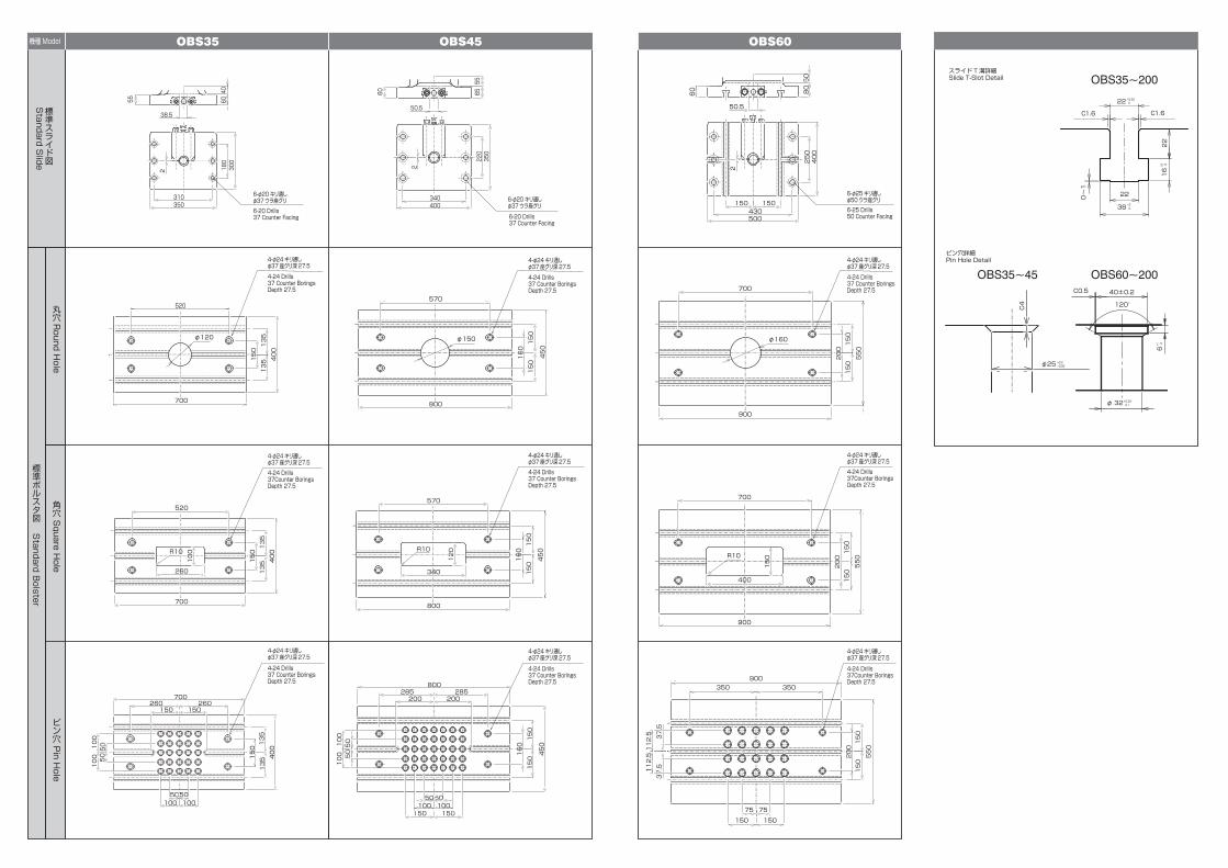
OBS35~200
OBS60~200OBS35~45
OBS45 OBS60
標準スライド図
Standard S
lide
標準ボルスタ図
Standard B
olster
丸穴R
ound Hole
角穴 S
quare Hole
ピン穴 P
in Hole
機種Model
スライド T溝詳細Slide T-Slot Detail
ピン穴詳細Pin Hole Detail
310350
180
300
55
2
38.5
4060
220
340
2
350
400
6560
50.5
55 50
60
50.5
2
80
400
500
150 150
250
430
700
520
135
135 φ120
520
135
135
700
260
R10
100
135
260700
135
260
50 100
50100
50
100
100 50
150 150
450
150
150
800
570
φ150
570
150
150
800
340
R10
150
285 800
150
150
285
50100
150 100 50
50 100
100 50
200 200
900
700
550
150
150
φ160
700
550
150
150
900
400
150 R10
150
550
350
150
350
150
150
900
75 75
37.5
112.5
37.5
112.5
120°
40±0.2
32φ
6
C0.5
22
22
16
22
38
0~1
1.6C1.6C
φ25
C4
160
150
400
400
150
160
450
120
160
450
150
400
200
200
200
6-φ20キリ通し φ37ウラ座グリ
4-φ24キリ通し φ37座グリ深27.5
6-φ20キリ通し φ37ウラ座グリ
6-20 Drills37 Counter Facing 6-20 Drills
37 Counter Facing
6-25 Drills50 Counter Facing
4-24 Drills 37 Counter Borings Depth 27.5
4-φ24キリ通し φ37座グリ深27.54-24 Drills 37Counter Borings Depth 27.5
4-φ24キリ通し φ37座グリ深27.5
4-24 Drills 37 Counter Borings Depth 27.5
4-φ24キリ通し φ37座グリ深27.5
4-24 Drills 37 Counter Borings Depth 27.5
4-φ24キリ通し φ37座グリ深27.5
4-24 Drills 37Counter Borings Depth 27.5
4-φ24キリ通し φ37座グリ深27.54-24 Drills 37 Counter Borings Depth 27.5
4-φ24キリ通し φ37座グリ深27.54-24 Drills 37Counter Borings Depth 27.5
4-φ24キリ通し φ37座グリ深27.54-24 Drills 37 Counter BoringsDepth 27.5
4-φ24キリ通し φ37座グリ深27.54-24 Drills 37 Counter Borings Depth 27.5
6-φ25キリ通し φ50ウラ座グリ
+0.52 0
+2 0
+0.25 0.1
+0.2+0.05
+1 0+2 0
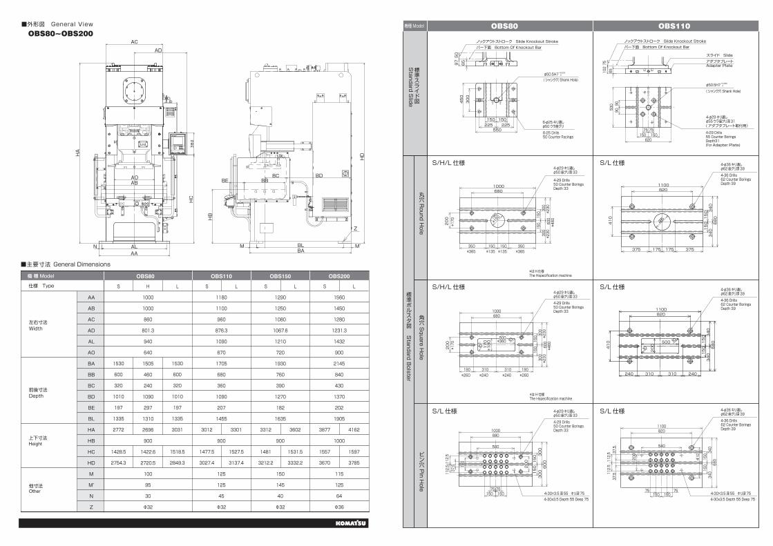
■外形図 General View
仕様 Type
AA
AB
AC
AD
AL
AO
BA
BB
BC
BD
BE
BL
HA
HB
HC
HD
M
M’
N
Z
左右寸法
前後寸法
上下寸法
他寸法
Width
Depth
Height
Other
機 種 Model
S H
1000
1000
860
801.3
940
640
1505
460
240
1090
297
1310
2696
900
1422.6
2720.5
100
95
30
Φ32
1530
600
320
1010
197
1335
2772
1428.5
2754.3
1530
600
320
1010
197
1335
3031
1518.5
2849.3
3012
1477.5
3027.4
3301
1527.5
3137.4
L
■主要寸法 General Dimensions
OBS80
S
1180
1100
960
876.3
1090
670
1705
680
360
1090
207
1455
900
125
125
45
Φ32
3312
1481
3212.2
3602
1531.5
3332.2
1290
1250
1080
1067.6
1210
720
1930
760
390
1270
182
1635
900
150
145
40
Φ32
3877
1557
3670
4162
1597
3785
1560
1450
1280
1231.3
1432
900
2145
840
430
1370
202
1905
1000
115
125
64
Φ36
L S
OBS110 OBS150
L S L
OBS200
AA BABL
BDBCBBBE
AL
AO
AD
AB
AC
HA
HC
HB
HD
N M M’
Z
OBS80~OBS200
標準スライド図
Standard S
lide
標準ボルスタ図
Standard B
olster
丸穴R
ound Hole
角穴 S
quare Hole
ピン穴 P
in Hole
機種Model OBS80
OBS110
S/H/L 仕様 S/L 仕様
S/H/L 仕様 S/L 仕様
S/L 仕様 S/L 仕様
225225
300
65
450
150150
550
9750
7575
909053
065
150620150
10275
350
1000
200
*365
*260 *260*240 *240
*365*135 *135
*170
*170
*460
*230
*はH仕様 The Hspecification machine
*はH仕様 The Hspecification machine
680
350
*15018
0
150150
300
*230
300
150 600
*460
*230
300
*230
300
600
150
310
10 170
*180
310190
500*360 10
190
150
150
6801000
200
1000680
300150 600300
150
112.5
112.5
75150 150
75
160
175175 375375
1100820
410
225
680340
150
340150
310310 240240
200
500
10
10
410 150
150
340680340
8201100
410
150
150
340
680
340
8201100
75150150
75
37.5
112.5 37.5
112.5
540
200
37.5 200
500
φ50.5H7(シャンク穴 Shank Hole)
( シャンク穴 Shank Hole)
+0.030 0
φ50.5H7 +0.030 0
4-φ29キリ通し φ50座グリ深334-29 Drills 50 Counter Borings Depth 33
4-φ29キリ通し φ50座グリ深33
4-29 Drills 50 Counter Borings Depth 33
ノックアウトストローク Slide Knockout Strokeバー下面 Bottom Of Knockout Bar
ノックアウトストローク Slide Knockout Stroke
スライド Slide
( アダプタプレート取付用)
バー下面 Bottom Of Knockout Bar
6-φ25キリ通し φ50ウラ座グリ6-25 Drills50 Counter Facings
4-φ29キリ通し φ55ウラ座グリ深31
4-29 Drills55 Counter BoringsDepth31(For Adapter Plate)
4-φ36キリ通し φ62座グリ深394-36 Drills62 Counter Borings Depth 39
4-φ36キリ通し φ62座グリ深394-36 Drills62 Counter Borings Depth 39
4-φ36キリ通し φ62座グリ深394-36 Drills62 Counter Borings Depth 39
4-φ29キリ通し φ50座グリ深33
4-30×3.5 深 55 キリ深754-30x3.5 Depth 55 Deep 75
4-30×3.5 深 55 キリ深754-30x3.5 Depth 55 Deep 75
4-29 Drills50 Counter Borings Depth 33
アダプタプレート Adapter Plate

OBS35~60 OBS80~200
■能力線図 Capacity Curves
標準スライド図
Standard S
lide
標準ボルスタ図
Standard B
olster
丸穴R
ound Hole
角穴 S
quare Hole
ピン穴 P
in Hole
機種Model OBS200
OBS150
S/L 仕様 S/L 仕様
S/L 仕様 S/L 仕様
S/L 仕様 S/L 仕様
7575
75
909055
0
150150300300
700
117
75
9090
7575150150300300
132
650
850
8090
760
185185 440440
9201250
250
440
380
150
300
380
300
150
360360 265265
600 10
10 220
150
150
300
380
760
380
300
1250920
440
75150225
150
150
300
380
760
380
300
1250920
440
112.5
112.5
37.5
37.5
75150225
420
420
840
515515 210210
420
1120
300
300150
300
150
1450
340340 385385
10650
240
10
150
300
420
150 840
420
300
14501120
420
150
300
420
150 840
420
300
14501120
420
225150
75
225150
75
112.5
112.5
300300
730
310
187.5
187.5
37.5
37.5
500 200015001000
OBS80OBS110OBS150OBS200
OBS80
500 200015001000
OBS80OBS110OBS150OBS200
OBS60
OBS60
OBS60OBS45OBS35
OBS45
OBS35
OBS45
OBS35
許容荷重Allowable Load kN
許容荷重Allowable Load kN
許容荷重Allowable Load kN
標準ストローク (S) Standard Stroke(S) 標準ストローク (S) Standard Stroke(S)
ショートストローク (H) Short Stroke(H)
ロングストローク (L) Long Stroke(L)
下死点からの高さ
20001
2
3456810
20
3040506070
1
2
3456810
20
30405060
400 600 0
Heght From BDC(mm)
ショートストローク (H) Short Stroke(H)
下死点からの高さ
20001
2
3456810
20
3040506070
400 600
Heght From BDC(mm)
許容荷重Allowable Load kN
ロングストローク (L) Long Stroke(L)
下死点からの高さ
20001
2
3456810
20
3040506070
400 600
Heght From BDC(mm)
下死点からの高さ
Heght From BDC(mm)
500 200015001000
OBS80
許容荷重Allowable Load kN
許容荷重Allowable Load kN
1
2
3456810
20
30405060
0
0
下死点からの高さ
Heght From BDC(mm)
1
2
3456810
20
30405060
下死点からの高さ
Heght From BDC(mm)
( シャンク穴 Shank Hole)3-φ50.5H7+0.030
0
スライド Slideアダプタプレート Adapter Plate
スライド Slideアダプタプレート Adapter Plate
ノックアウトストロークSlide Knockout Strokeバー下面 Bottom Of Knockout Bar
ノックアウトストローク Slide Knockout Strokeバー下面 Bottom Of Knockout Bar
( アダプタプレート取付用) (アダプタプレート取付用)
4-φ29キリ通し φ55座グリ深31
4-29 Drills55 Counter BoringsDepth31(For Adapter Plate)
4-29 Drills55 Counter BoringsDepth31(For Adapter Plate)
( シャンク穴 Shank Hole)3-φ50.5H7+0.030
0
4-φ29キリ通し φ55座グリ深31
4-φ36キリ通し φ62座グリ深39
4-36 Drills 62 Counter Borings Depth 39
4-φ36キリ通し φ62座グリ深39
4-36 Drills 62 Counter Borings Depth 39
4-φ36キリ通し φ62座グリ深39
4-36 Drills 62 Counter Borings Depth 39
4-φ36キリ通し φ62座グリ深39
4-36 Drills 62 Counter Borings Depth 39
4-φ36キリ通し φ62座グリ深39
4-36 Drills 62 Counter Borings Depth 39
4-φ36キリ通し φ62座グリ深39
4-36 Drills 62 Counter BoringsDepth 39