![[Vietnam]hanbiro- Tsg](https://static.fdocument.pub/doc/165x107/58f0ae9b1a28ab95728b45a9/vietnamhanbiro-tsg.jpg)
3GPP TSG RAN Meeting #19 RP-030122 Birmingham, United Kingdom, 11
61
3GPP TSG RAN Meeting #19 RP-030122 Birmingham, United Kingdom, 11 – 14 March 2003 3GPP TSG-RAN WG4 Meeting #26 R4-030348 Madrid, Spain, 17-22 February 2003 Title: LS on Antenna Interface Standards Group (AISG) Response to: Release: Work Item: Source: RAN4 To: RAN Cc: Contact Person: Name: Mike Vogel Tel. Number: +49 211 533 2923 E-mail Address: [email protected] Attachments: [1] TSG-RAN WG 4 #26 Madrid, Spain, 17 th – 21 st February 2003 R4-030140, “Information about Antenna Interface Standards Group (AISG) first public draft specification”, Vodafone Group 1. Overall Description: At TSG RAN4 #26 meeting (Madrid, Spain, 17-22 February 2003) the status of the “Antenna Interface Standards Group” (AISG) work was presented by Vodafone. The objective of the contribution was to inform TSG RAN WG4 about the first public draft AISG specification and kindly ask the delegates to examine the AISG specification regarding the WG4 related aspects and to start the discussion on this topic. During the discussion at RAN#4 some concerns on the AISG draft specification and the way forward were raised. Therefore RAN4 would like to ask RAN for their opinion and guidance on how to proceed with the AISG draft. The following comments were pointed out during the meeting: 1. It is unclear in which way the AISG proposals could be combined with the work in current RAN4 specifications. 2. The reference point used for performance requirements of the base station is the antenna port. In the current European R&TTE directive requirements all tests are performed at this reference point, it is unclear how these tests would be performed when a base station supporting the in-band signalling is tested (for example the in-band signal spectrum mask would fail the spurious requirements). RAN 4 is also aware of similar requuirement in other regions of the world. 3. It is assumed that a new port as recommended by AISG would need to be define new performance requirements. It is not clear in which way such requirements could be defined. Some more specific comments were addressed regarding the AISG1 draft. Also RAN is kindly asked to inform AISG about the issues listed below. 4. The Spectrum mask figure in the AISG1 draft 8 (sect 6.6.2, fig 6.6.6.2 for 'Intermediate Frequency' / 'Sub carrier') and Spurious Emissions fig 3 of [1] refer and apply to both ‘a’ and ‘b’ connection arrangements. The suggestion is to extend the upper measurement band to 12.75GHz and lower limit to 9kHz, and use the
Transcript of 3GPP TSG RAN Meeting #19 RP-030122 Birmingham, United Kingdom, 11

3GPP TSG RAN Meeting #19 RP-030122 Birmingham, United Kingdom, 11 – 14 March 2003 3GPP TSG-RAN WG4 Meeting #26 R4-030348 Madrid, Spain, 17-22 February 2003 Title: LS on Antenna Interface Standards Group (AISG)
Response to:
Release:
Work Item:
Source: RAN4
To: RAN
Cc:
Contact Person: Name: Mike Vogel Tel. Number: +49 211 533 2923 E-mail Address: [email protected]
Attachments: [1] TSG-RAN WG 4 #26 Madrid, Spain, 17th – 21st February 2003
R4-030140, “Information about Antenna Interface Standards Group (AISG) first public draft specification”, Vodafone Group
1. Overall Description:
At TSG RAN4 #26 meeting (Madrid, Spain, 17-22 February 2003) the status of the “Antenna Interface Standards Group” (AISG) work was presented by Vodafone. The objective of the contribution was to inform TSG RAN WG4 about the first public draft AISG specification and kindly ask the delegates to examine the AISG specification regarding the WG4 related aspects and to start the discussion on this topic. During the discussion at RAN#4 some concerns on the AISG draft specification and the way forward were raised. Therefore RAN4 would like to ask RAN for their opinion and guidance on how to proceed with the AISG draft. The following comments were pointed out during the meeting: 1. It is unclear in which way the AISG proposals could be combined with the work in current RAN4 specifications.
2. The reference point used for performance requirements of the base station is the antenna port. In the current European R&TTE directive requirements all tests are performed at this reference point, it is unclear how these tests would be performed when a base station supporting the in-band signalling is tested (for example the in-band signal spectrum mask would fail the spurious requirements). RAN 4 is also aware of similar requuirement in other regions of the world.
3. It is assumed that a new port as recommended by AISG would need to be define new performance requirements. It is not clear in which way such requirements could be defined.
Some more specific comments were addressed regarding the AISG1 draft. Also RAN is kindly asked to inform AISG about the issues listed below.
4. The Spectrum mask figure in the AISG1 draft 8 (sect 6.6.2, fig 6.6.6.2 for 'Intermediate Frequency' / 'Sub carrier') and Spurious Emissions fig 3 of [1] refer and apply to both ‘a’ and ‘b’ connection arrangements. The suggestion is to extend the upper measurement band to 12.75GHz and lower limit to 9kHz, and use the
measurement bandwidth as identified in 3GPP TS 25.104v6.0.0 (2002-12) “BS Radio transmission and Reception (FDD) (Release 6)” table 6.8: BS Mandatory spurious emissions.
5. Interoperability issues for AISG1 ‘a’ using the Intermediate Frequency or Sub-carrier based systems. The Bias Tee power supply arrangement of terminating Antenna Line devices needs a definitive value. A value of reactance and tolerance could be specified which can then be used to determine the maximum DC inrush current for the system. The system can then be designed to cope with this demand. This has multiple advantages to define the overall operation specifications of the TTE-system and aid interoperability issues when multiple Remote Electrical Tilt Antenna (RET) and/or other Antenna Line devices is daisy chained. By defining a value and tolerance, the Antenna Feeder system RF performances can be more accurately assessed for Cell RF coverage purposes, and vendor equipment can be specified for filter losses, sub-carrier, Bias Tee and miscellaneous incidental losses. The consequence of not specifying an interoperability range is that each RF connection will need to be individually corrected.
2. Actions:
RAN is kindly asked to give some guidance how to proceed with the topics 1, 2 and 3 and to inform the AISG
about this document.
3. Date of Next Meetings:
RAN4_27 19-23 May 2003 Paris, France
RAN4_28 18-22 August China

TSG-RAN Working Group 4 Meeting #26 R4-030140 Madrid, Spain February 17-21, 2003 Agenda Item: 12. Any other business Source: Vodafone Group Title: Information about Antenna Interface Standards Group
(AISG) first public draft specification Document for: Information
1. Introduction
In the TSG RAN#14 meeting (Kyoto, Japan, 11 – 14 December 2001) a Work Item for an "Interface to control electrical tilting of antennas" was proposed. According to the outcome of the discussion TSG RAN decided to instruct TSG RAN3 to draft a WI for RAN#15 on the topic of the postponed WI presented at RAN#14 [1].
At that time an international forum called the Antenna Interface Standards Group (AISG) started writing a standard (AISG-1) to define such an interface including signalling protocol between a logical Remote Electrical Tilting (RET) antenna and the logical Node B. Therefore, it was proposed by Vodafone Group at TSG RAN3#29 meeting (Gyeongju, South Korea, 13 – 17 May 2002) not to carry out any work on this topic within TSG RAN at that time and wait for the AISG specification [2].
AISG has grown rapidly into an informal organization with more than 40 companies either in full membership (party to the NDA) or associate membership (receiving only specification drafts). Further information about AISG are available at http://www.aisg.org.uk and were presented at the TSG RAN#16 meeting (Marco Island, FL, USA, 4 – 7 June 2002) by Vodafone Group [3].
At TSG RAN#18 meeting (New Orleans, Louisiana, USA, 3 – 6 December 2002) the status of the AISG work was presented by Vodafone Group [4]. It was clarified that the technical work has been finished in AISG. A first public version of the draft AISG standard [5] was published in November 2002 and is available at http://www.aisg.org.uk. This first public draft specification provides a means of addressing antennas and antenna -line equipment using a simple HDLC-based protocol, terminating at a defined interface at the Node B / BTS. A reviewing process is ongoing at the moment. The next steps will be to correct this standard if needed and to establish an appropriate form of legal entity for AISG to be acceptable by 3GPP (in particular in relation with ETSI and ETSI IPR policy). For this purpose AISG is being re-formed at the moment to get a form of a UK "company limited by guarantee". Unfortunately this re-forming process takes much longer than initially expected. Once this legal status has been achieved a request is expected to be addressed to 3GPP PCG in order to agree a formal collaboration between 3GPP and AISG.
During the discussion at RAN#18 some concerns on the AISG specification were pointed out (e.g. intermodulation in transceivers, tower mast amplifier as possible device by AISG while not defined in 3GPP). Finally, it was requested by TSG RAN to present the public draft AISG

specification in TSG RAN WG3 and WG4 for examination of the new interface and its impact on the RF conditions at the antenna port.
Therefore, this document shall inform TSG RAN WG4 about the first public draft AISG specification and kindly ask the delegates to examine the AISG specification regarding the WG4 related aspects and to start the discussion on this topic.
2. Discussion
In the present UMTS Radio Access Network antennas with variable electrical tilting are needed to adjust the coverage area including soft handover areas. Due to the interference limited property of the UMTS Radio Access Technology this adjustment is essential for optimising and operating the UMTS network.
Figure 1
Current solutions would lead to costly site visits and antenna climbing. They as well as the ones currently in development are proprietary and will lead to incompatibility problems or work-around solutions. Furthermore, a mix of antennas and Node Bs from different vendors is not possible without a standardised interface.
A new interface between RET antenna and Node B to control the electrical tilting remotely as shown in figure 1 is needed to be specified to ensure vendor independency and to minimise cost. A viable solution should be assessed to be specified for UTRAN.
The AISG document defines a standard data interface at an antenna line device by means of which functional parameters of the device can be remotely controlled; specifically it defines the requirements of a three-layer protocol model.

Antenna line devices may include RET antennas, TMAs, boosters, VSWR measuring units and other tower-top equipment. All these (and others) can be implemented using the system described in the AISG standard.
Figure 2 illustrates both a direct RS485 connection between a Node -B/BTS and towertop equipment, and the alternative system (B) in which a coaxial cable is used to carry power as well as data and RF signals. When a coaxial cable is used it terminates at a layer-1 converter (usually inside a TMA) and an RS485 data connection is made to the antenna.
Figure 2
Some of the following statements from which we assume that they could be related to the RAN WG4, we would gladly present for discussion. They are described in chapter 6.6 of the AISG draft. :
?? Interference with Existing Systems:
It is noted that „...The modem must not interfere with existing communications in BTS systems, so a unique carrier frequency for each different communication channel on a common feeder cable is necessary. It will be appreciated that each carrier is capable of supporting separate logical channels, each of which can support a separate RS485 bus. Frequencies already known to be in use for proprietary systems are listed in Appendix F of the AISG specification.
The modem circuit must be capable of managing its transmitting characteristic and providing filtering for its receiver. The following frequencies are specified for future use for this application:
4.5 MHz +/- 100ppm

9.0 MHz +/- 100ppm...“
?? Impedance
„The modem transceiver shall provide constant impedance in both transmitting and
receiving modes
Nominal impedance Z0: 50 Ohm
Return loss at nominal carrier frequency >6dB“
?? Spurious Emissions
Spurious emissions shall not exceed the mask shown in figure 3.
Intermediate values may be obtained by linear interpolation between the points
shown.
Figure 3
?? Demodulator Characteristics
The demodulator characteristics have been defined on the assumption of a minimum separation of 2MHz for adjacent carriers on the same coaxial cable. This must be taken into consideration when choosing the operating frequency f0.
?? Threshold
Threshold: -15 dBm ??3 dB
?? Filter Characteristics
Bandwidth ( 3 dB): min. f0 ??350 kHz
Bandwidth (25 dB): max. f0 ??800 kHz
3. Conclusion
This document was presented to inform the RAN WG4 attending companies about the activities in the AISG. RAN4 is kindly asked to review the draft specification of AISG standard, which is attached to this document, to evaluate any potential RF impact of this new interface.
4. References
[1] RP-010834 "Proposed Work Item 'Interface to control electrical tilting of antennas'"; Mannesmann Mobilfunk GmbH, Omnitel-Vodafone, Deutsche Telekom MobilNet, Eplus, Vodafone Group, Telecom Italia; TSG RAN#14, Kyoto, Japan
[2] R3-021584 "Proposed Handling for Remote Electrically Tilting (RET) Antennas Work in TSG RAN"; Vodafone Group; TSG RAN3#29, Gyeongju, South Korea
[3] RP-020451 "Overview of the Antenna Interface Standards Group (AISG)"; Vodafone Group; TSG RAN#16, Marco Island, FL, USA
[4] RP-020853 "Status of Antenna Interface Standards Group (AISG) work"; Vodafone Group; TSG RAN#18, New Orleans, Louisiana, USA
[5] AISG Standard No. AISG1 "Control Interface for Antenna Line Devices", 1st Public Draft 7.3, 29 th October 2002
[6] R3-030082 "Information about Antenna Interface Standards Group (AISG) first public draft specification "; TSG RAN WG3 #34; Sophia Antipolis, France, 17 – 21 February 2003

Antenna Interface Standards GroupStandard No. AISG1: Draft 8
(1st Public Draft) 18 November 2002
Protocol Specification AISG1 Draft 8, Nov 18, 2002 Page 1 of 54
Control interface for antenna line devices
Revision History
DATE ISSUE NOTES03rd March 2002 AISG-23 Original Issue AISG-23
12 Oct 2002 AISG-53 TMA interface incorporated
18 Nov 2002 AISG-55 Issued for public comment
© Copyright Antenna Interface Standards Group 2002

Antenna Interface Standards GroupStandard No. AISG1: Draft 8
(1st Public Draft) 18 November 2002
Protocol Specification AISG1 Draft 8, Nov 18, 2002 Page 2 of 54
CONTENTS
1 Foreword 52 Scope 63 References 84 Abbreviations 95 Terminology 106 Layer 1 126.1 Antenna line network 126.1.1. Network current consumption 126.1.2. Maximum ALD network current demand 126.1.3. Overcurrent protection 126.2. Interface Connector types 136.2.1. Multi-pole connector 136.2.2. Polarity of multi-pole connectors 136.2.3. Coaxial connectors 146.3. DC supply 146.3.1. Supply voltage 146.3.2. Noise and ripple 146.4. Current consumption 146.4.1. RET DC supply 146.4.2. TMA DC supply 146.4.3. ALD network DC supply 156.4.4. ALD DC Supply Start-up Surge 156.4.5. DC supply via LOC 156.4.6. Re-start capability of the power supply at a primary station 176.5. RS485 serial data bus 176.5.1. Connections 176.5.2. Device terminating impedance 176.5.3. Bus terminating impedance 176.6. Coaxial interface: modem characteristics 176.6.1. Interference With Existing Systems 176.6.2. Data Rate 186.6.3. Recovery Time 186.6.4. Impedance 186.6.5. Modulation 186.6.6. Modulator characteristics 186.6.6.1 Levels 186.6.6.2 Spurious emissions 186.6.7. Demodulator characteristics 196.6.7.1 Threshold 196.6.7.2 Filter Characteristics 196.6.7.3 Duty Cycle variation 196.7. Data rate & format 206.7.1. Data Rate 206.7.2. Data Format 206.8. Resumption of operation after interruption of supply 206.8.1. Device Type 1 20

Antenna Interface Standards GroupStandard No. AISG1: Draft 8
(1st Public Draft) 18 November 2002
Protocol Specification AISG1 Draft 8, Nov 18, 2002 Page 3 of 54
6.8.2 Device Type 2 206.8.2. Device Type 3 216.9. Idle-state biasing 217. Layer 2 227.1. HDLC Format 227.1.1. Operating Mode 227.1.2. Control octet transparency 227.2. Frame checking sequence (FCS) field 227.3. HDLC Command Sub-set 227.3.1. I-frame and INFO-field format 237.3.2. Version ID 237.3.3. SNRM frame data format 237.4. Address 237.4.1. Address 0x00 237.4.2. Address 0xFF 247.4.3 Address configuration 247.4.3.1 Address assignment command 247.4.3.2 Address Assignment Response 247.4.3.3 Device scan command 257.4.3.3.1 Primary command (XID frame) 257.4.3.3.2 Device Scan Response (XID) 257.5. Window Size ( minimum) 267.6. Connection Establish 267.7. Disconnect 267.8. Polling 267.9. Information 277.10. Message timing 277.10.1. Primary Station Poll 277.10.2. Secondary Station Frame response 277.10.3. Recovery Time 277.11. Frame Error Rate 278. Layer 7 288.1. Command Format 288.2. Response format and return codes 288.3. Overview of commands 288.4. Global Command Interface – Mandatory for all Devices 308.4.1. Get Device Type 308.4.2. Reset Software 318.4.3. Error Detection 318.4.4. Read Hardware and Software Information 318.4.5. Clear stored Alarms 328.4.6. Poll response from Secondary Station 328.4.7. Enable Device 338.4.8. Disable Device 338.4.9. Self Test 338.4.10. Read and Write Memory 348.4.10.1 Read Memory 348.4.10.2 Write Memory 358.4.11. Get supported bit rates 35

Antenna Interface Standards GroupStandard No. AISG1: Draft 8
(1st Public Draft) 18 November 2002
Protocol Specification AISG1 Draft 8, Nov 18, 2002 Page 4 of 54
8.4.12. Set Device Data 358.4.13 Get Device Data 358.4.14 Software Download (Optional feature) 368.4.14.1 Download Start 368.4.14.2 Store Data Start 368.4.14.3 Store Data Block Segment 378.4.14.4 Download End 378.4.16 Optional command: Set bit rate 378.4.16.1 Set Bit Rate Procedure 388.5. Device Specific Commands for a RET 398.5.1. Calibration 398.5.2. Send RET Configuration data 408.5.3. Set Tilt 408.5.4. Get Tilt 408.6. Specific commands for a TMA 418.6.1. Set TMA Mode 418.6.2. Get TMA Mode 418.6.3. Set TMA Gain 428.6.4. Get TMA Gain 428.7. Vendor Specific Commands 428.8. Unknown Commands 438.9. Additional commands for control and telemetry 439. Additional requirements 449.1. Electromagnetic compatibility 449.2. Lightning protection 449.3. Reliability 4310. Product identification 4510.1. Marking of conforming products 4510.2. Use of the AISG name and logo 4510.3 Vendor ID and Serial Number 44
Appendix A: Assigned vendor codes 46Appendix B: Assigned device types 46Appendix C: Assigned return codes 47Appendix D: Assigned fields for additional data 49Appendix E: Sequence for download of software to a secondary station 52Appendix F: Frequencies reserved for proprietary use for signalling in coaxial
cables 53Appendix G: Product specification compatibility 54

Antenna Interface Standards GroupStandard No. AISG1: Draft 8
(1st Public Draft) 18 November 2002
Protocol Specification AISG1 Draft 8, Nov 18, 2002 Page 5 of 54
1 FOREWORD
This draft standard has been produced by the Antenna Interface Standards Group tofacilitate the introduction of antenna line products with remote control and monitoringfacilities.
The purpose of this standard is to ensure basic interoperability of antennas and controlinfrastructure.
At the date of publication of this document, the following companies were members ofthe Antenna Interface Standards Group:
ADC, Inc Huber + Suhner AGAlan Dick & Co Ltd Jacquelot Technologies SAAllgon Systems AB Jaybeam LtdAndrew Corporation Kathrein KGAntenova Ltd KMW LtdArgus Technologies (Australia) Pty Ltd LGP ABBöke & Walterfang Ltd Lucent TechnologiesCelletra, Inc MAT Equipement SACSA Ltd Mitec IncDAPA Systèmes SA O2 (UK) LtdDecibel Products Inc ProximusEMS Technologies, Inc. Quintel S4 LtdETSA (Européenne de Télécommunications) REMEC IncEyecom Technologies RFS IncEyecom NZ Ltd. RYMSA SAFiltronic Ltd Siemens AGForem spa Sigma Wireless Technologies LtdFractus SA T-Mobile InternationalGamma Nu Inc Thales Antennas LtdHitachi Cable Co Ltd TIMHuber + Suhner Ltd University of Sheffield (UK)
Vodafone Group
A number of aspects of this specification are subject to extension and development toaccommodate new requirements. Members are recommended to consult the AISGWebsite (www.aisg.org.uk) for information on current or forthcoming updates.

Antenna Interface Standards GroupStandard No. AISG1: Draft 8
(1st Public Draft) 18 November 2002
Protocol Specification AISG1 Draft 8, Nov 18, 2002 Page 6 of 54
1 SCOPE
This document defines a standard data interface at an antenna line device by means ofwhich functional parameters of the device can be remotely controlled; specifically itdefines the requirements of a three-layer protocol model. The three-layer model is acompact form of the OSI seven-layer reference model and includes only layers 1, 2 and7. The advantage of this compact model is that it provides an efficient protocol stacksuitable for implementation on a single embedded microcontroller.
Layer 1, the physical layer, defines the signalling levels, basic data characteristicsincluding baud rate and the preferred input connector.
Layer 2, the data link layer, is based on a custom subset of the HDLC standard asdefined in ISO/IEC 13239:2000(E).
Layer 7, the application layer, defines the data payload format and the requiredcommand set.
Figure 1: Schematic diagram showing the equipment and interfaces specified in this standard.
Figure 1 illustrates both a direct RS485 connection between a Node-B/BTS and tower-top equipment, and the alternative system (B) in which a coaxial cable is used to carrypower as well as data and RF signals. When a coaxial cable is used it terminates at a
A
B
RS485 Layer-1uses multicorescreened cable
(A)
Coaxial Layer 1
Tower TopEquipment
AISG1defines thisInterface
Base Station
RS485 Layer 1AISG1 defines thisinterface.
AISG1 defines powerand data communicationwithin the dotted areausing either a continuousRS-485 bus or a coaxialcable and Layer-1converter.
Layer-oneconverterLOC
Coaxial layer 1shares RFcoaxial cable
(B)
Antenna Interface Standards GroupStandard No. AISG1: Draft 8
(1st Public Draft) 18 November 2002
Protocol Specification AISG1 Draft 8, Nov 18, 2002 Page 7 of 54
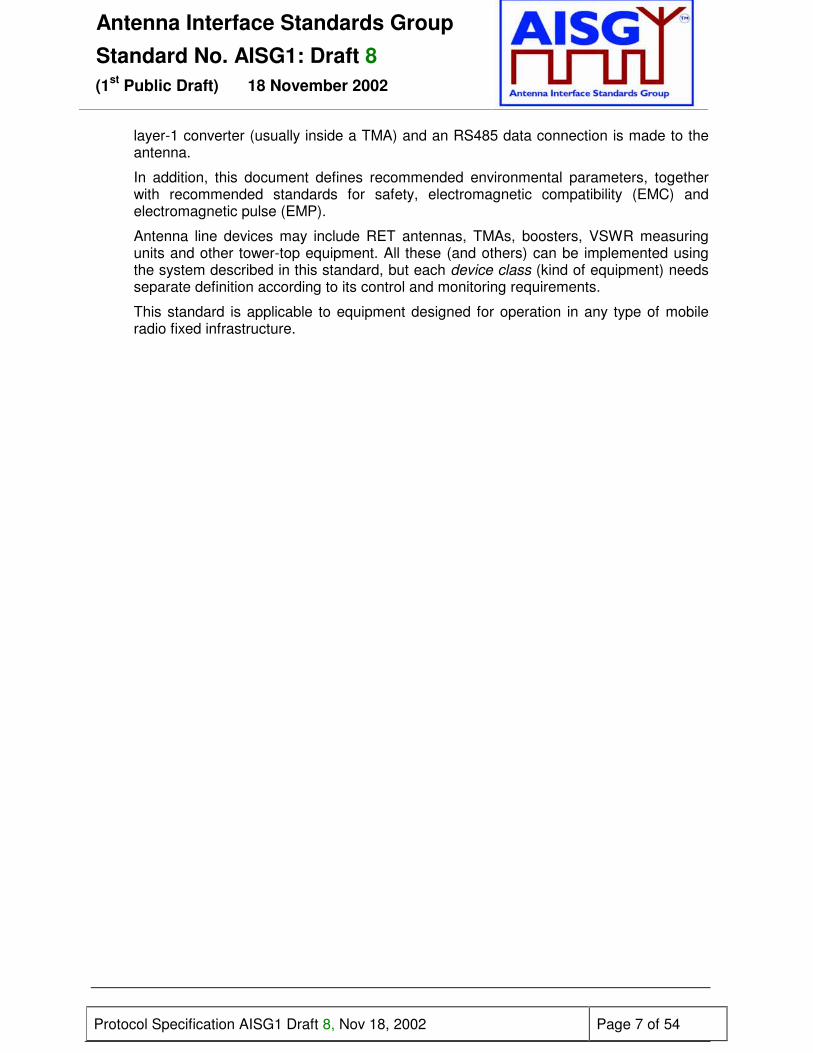
layer-1 converter (usually inside a TMA) and an RS485 data connection is made to theantenna.
In addition, this document defines recommended environmental parameters, togetherwith recommended standards for safety, electromagnetic compatibility (EMC) andelectromagnetic pulse (EMP).
Antenna line devices may include RET antennas, TMAs, boosters, VSWR measuringunits and other tower-top equipment. All these (and others) can be implemented usingthe system described in this standard, but each device class (kind of equipment) needsseparate definition according to its control and monitoring requirements.
This standard is applicable to equipment designed for operation in any type of mobileradio fixed infrastructure.

Antenna Interface Standards GroupStandard No. AISG1: Draft 8
(1st Public Draft) 18 November 2002
Protocol Specification AISG1 Draft 8, Nov 18, 2002 Page 8 of 54
3 REFERENCES
This AISG standard incorporates provisions from other publications. These are cited in thetext and the referenced publications are listed below. Where references are dated,subsequent amendments or revisions of these publications apply only when specificallyincorporated by amendment or revision of this AISG standard. For undated references thelatest edition of the publication referred to applies.
1 EMC Directive, 83/336/EEC
2 ETS 300 242 2 Radio equipment and systems (RES): Electromagnetic compatibility (EMC)for European digital cellular communications system (GSM 900MHz and DCS 1800MHz);Part 2: Base station radio and ancillary equipment
3 ETS 301 489 8 Electromagnetic compatibility and radio spectrum matters (ERM);Electromagnetic compatibility (EMC) standard for radio equipment and services; Part 8:Specific conditions for GSM base stations
4 ETS 301 489 23 Electromagnetic compatibility and radio spectrum matters (ERM);Electromagnetic compatibility (EMC) standard for radio equipment and services; Part 23:Specific conditions for IMT-2000 CDMA Direct Spread (UTRA) base station (BS) radio,repeater and ancillary equipment
5 IEC 60130-9 (Ed. 3.0, May 2000): Connectors for frequencies below 3 MHz – Part 9:Circular connectors for radio and associated sound equipment
6 IEC 60529 (Feb 2001): Degrees of protection provided by enclosures (IP Code)
7 IEC 61000-4-5 01-Feb-1995 Electromagnetic compatibility (EMC) - Part 4: Testing andmeasurement techniques - Section 5: Surge immunity test
8 IEC 62305-4 Protection against lightning – Part 4: Electrical and electronic systems withinstructures
9 IEC/TS 61312-4 Protection against lightning electromagnetic impulse – Part 4: Protectionof equipment in existing structures.
10 ISO/IEC 646:1991 Information technology – 7-bit coded character set for informationexchange
11 ISO/IEC 7498-1:1994: Information technology – Open Systems Interconnection BasicReference Model: The Basic Model
12 ISO/IEC 8482:1993: Information technology – Telecommunications and informationexchange between systems - Twisted pair multipoint interconnections
13 ISO/IEC 13239 (2nd Edition, March 2000): Information Technology – Telecommunicationsand information exchange between systems – High-level data link control (HDLC)procedures
14 RTTE Directive 99/5/EEC
15 TIA/EIA Telecommunications Systems Bulletin TSB89: Application guidelines for TIA/EIA-485-A, June 1998 (Telecommunications Industry Association)

Antenna Interface Standards GroupStandard No. AISG1: Draft 8
(1st Public Draft) 18 November 2002
Protocol Specification AISG1 Draft 8, Nov 18, 2002 Page 9 of 54
4 ABBREVIATIONS
Where abbreviations or acronyms are used in this document they have the followingmeanings:ADR AddressAIB Antenna interface bus (RS485)AIC Antenna interface connectorALAP Antenna line application protocolALD Antenna line deviceASK Amplitude shift keyingBER Bit error rateCRC Cyclic redundancy checkDISC Disconnect (frame type)DM Disconnected modeEMC Electromagnetic compatibilityEMP Electromagnetic pulseFCS Frame checking sequenceFRMR Frame reject (frame type)HDLC High-level data link controlI Information (frame type)INFO Information (field name)ISB Idle state biasingLOC Layer one (1) converterNRM Normal response modeNRZ-L Non-return-to-zero levelOOK On-off keyingOp mA Operating current (mA)OSI Open systems interconnection, as described in ISO/IEC 7498-1Q mA Quiescent current (mA)RET Remote electrical tilt unit (antenna drive unit)RR Receive ready (frame type)RNR Receive not ready (frame type)RS485 A physical interface conforming to ISO/IEC 8482 (ANSI-EIA RS485)SNRM Set normal response mode (frame type)TMA Tower-mounted amplifierTMB Tower-mounted boosterTTE Tower-top equipmentTWA Two-way alternate (half-duplex)UA Unnumbered acknowledgement (frame type)UART Universal asynchronous receiver/transmitterUNC Unbalanced operation normal response mode classXID Exchange ID (Frame type)
Antenna Interface Standards GroupStandard No. AISG1: Draft 8
(1st Public Draft) 18 November 2002
Protocol Specification AISG1 Draft 8, Nov 18, 2002 Page 10 of 54
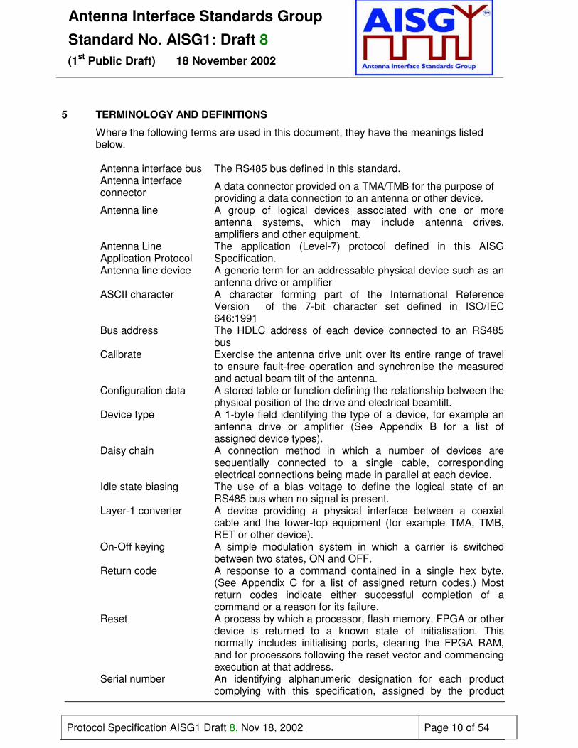
5 TERMINOLOGY AND DEFINITIONS
Where the following terms are used in this document, they have the meanings listedbelow.
Antenna interface bus The RS485 bus defined in this standard.Antenna interfaceconnector A data connector provided on a TMA/TMB for the purpose of
providing a data connection to an antenna or other device.Antenna line A group of logical devices associated with one or more
antenna systems, which may include antenna drives,amplifiers and other equipment.
Antenna LineApplication Protocol
The application (Level-7) protocol defined in this AISGSpecification.
Antenna line device A generic term for an addressable physical device such as anantenna drive or amplifier
ASCII character A character forming part of the International ReferenceVersion of the 7-bit character set defined in ISO/IEC646:1991
Bus address The HDLC address of each device connected to an RS485bus
Calibrate Exercise the antenna drive unit over its entire range of travelto ensure fault-free operation and synchronise the measuredand actual beam tilt of the antenna.
Configuration data A stored table or function defining the relationship between thephysical position of the drive and electrical beamtilt.
Device type A 1-byte field identifying the type of a device, for example anantenna drive or amplifier (See Appendix B for a list ofassigned device types).
Daisy chain A connection method in which a number of devices aresequentially connected to a single cable, correspondingelectrical connections being made in parallel at each device.
Idle state biasing The use of a bias voltage to define the logical state of anRS485 bus when no signal is present.
Layer-1 converter A device providing a physical interface between a coaxialcable and the tower-top equipment (for example TMA, TMB,RET or other device).
On-Off keying A simple modulation system in which a carrier is switchedbetween two states, ON and OFF.
Return code A response to a command contained in a single hex byte.(See Appendix C for a list of assigned return codes.) Mostreturn codes indicate either successful completion of acommand or a reason for its failure.
Reset A process by which a processor, flash memory, FPGA or otherdevice is returned to a known state of initialisation. Thisnormally includes initialising ports, clearing the FPGA RAM,and for processors following the reset vector and commencingexecution at that address.
Serial number An identifying alphanumeric designation for each productcomplying with this specification, assigned by the product

Antenna Interface Standards GroupStandard No. AISG1: Draft 8
(1st Public Draft) 18 November 2002
Protocol Specification AISG1 Draft 8, Nov 18, 2002 Page 11 of 54
manufacturer and having a maximum length of 17 bytes. Theserial number is stored as ASCII characters (see above)rightaligned, with leading characters (if any) filled with zeros(0x00), thus: 00000SERIALNUMBER. This padding shall beprovided where necessary by the primary station, beforetransmitting a serial number.
Note that the combination of serial number and vendor codemay be used to address antenna line devices on one or morecomplete mobile radio networks, so each vendor mustmanage the allocation of serial numbers to ensure they arenever duplicated. The provision of the vendor code allowseach vendor to manage serial numbers independently inaccordance with their own established practice within theassigned field, the only constraint being that they are notrepeated.
Tilt (also downtilt, tiltangle, beamtilt) The angle between the direction orthogonal to the antenna
axis and the maximum of its main beam in the elevation plane.A positive tilt angle means that the antenna beam is directedbelow the horizontal plane. An antenna has separate valuesfor electrical and mechanical tilt. In the case of an antennawith an RET facility the electrical tilt is variable and iscontrolled by the interface described in this specification. Themechanical tilt is fixed by the geometry of the installation. Inthis specification the tilt referred to is always the electrical tiltunless otherwise stated.
Vendor code A unique ASCII 2-character code assigned by AISG to eachvendor manufacturing products conforming to thisspecification (See Appendix A for a list of assigned vendorcodes).

Antenna Interface Standards GroupStandard No. AISG1: Draft 8
(1st Public Draft) 18 November 2002
Protocol Specification AISG1 Draft 8, Nov 18, 2002 Page 12 of 54
1. LAYER 1
This standard specifies two layer-1 connection alternatives to antenna line devices(ALDs):
1. A screened multicore cable, which may be used with any ALD and supports a conventional RS485 serial multi-drop bus.
2. A connection to an ALD by way of a coaxial cable which is shared with DC supply and RF signals
Both layer-1 options support the connection of two-way serial data and DC power to theALDs. Three alternative DC supply voltages are specified.
Interconnection between the two specified layer-1 implementations is supported by alayer-1 converter (LOC).
6.1 Antenna line network
The RS485 implementation of layer-1 supports the connection of multiple ALDs formingan ALD network. Connections to multiple devices can be made using star or daisy-chainconfigurations.
When the connection topology requires one ALD to pass current to other downstreamALDs, it is important to ensure that each ALD can support the downstream currentrequirement.
6.1.1 Network current consumption
The total current consumption of an antenna line network is not specified as it willdepend on the size of the network, the ALDs used and the primary stationsoftware design.
6.1.2 Maximum ALD network current demand
A RET will exhibit high current consumption only for controlled and limited periods.An ALD network may therefore be designed to support a total current consumptionthat is lower than the sum of the maximum consumption of each ALD. It is theresponsibility of the ALD controller (ie the primary station) to avoid overload andsecure a stable operating voltage for the ALDs. Specifically the primary stationmust ensure that high current devices such as RETs are not operatedsimultaneously.
6.1.3 Overcurrent protection
No short circuit protection capability is specified in this standard for separateALDs. Attention is drawn to the need to avoid by design the possibility of damageto ALDs or interconnecting cables by short circuit faults, and to reduce thepossibility of multiple devices being disabled by a single fault.
Antenna Interface Standards GroupStandard No. AISG1: Draft 8
(1st Public Draft) 18 November 2002
Protocol Specification AISG1 Draft 8, Nov 18, 2002 Page 13 of 54
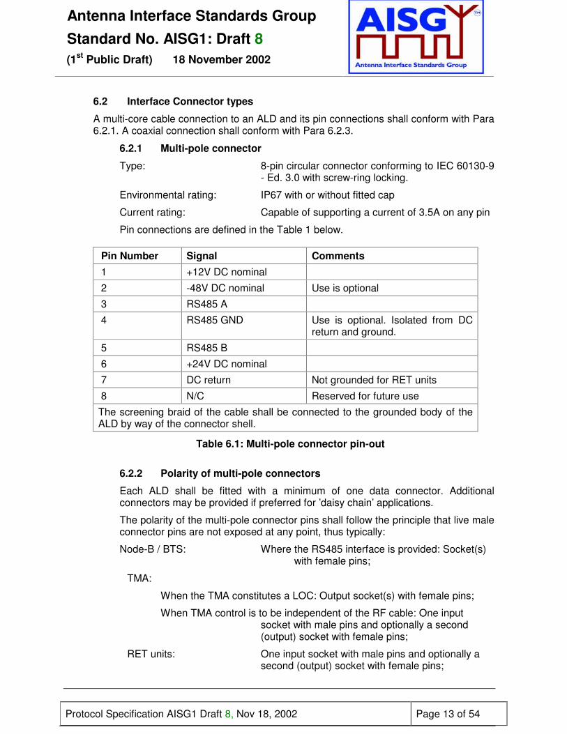
6.2 Interface Connector types
A multi-core cable connection to an ALD and its pin connections shall conform with Para6.2.1. A coaxial connection shall conform with Para 6.2.3.
6.2.1 Multi-pole connector
Type: 8-pin circular connector conforming to IEC 60130-9- Ed. 3.0 with screw-ring locking.
Environmental rating: IP67 with or without fitted cap
Current rating: Capable of supporting a current of 3.5A on any pin
Pin connections are defined in the Table 1 below.
Pin Number Signal Comments
1 +12V DC nominal
2 -48V DC nominal Use is optional
3 RS485 A
4 RS485 GND Use is optional. Isolated from DCreturn and ground.
5 RS485 B
6 +24V DC nominal
7 DC return Not grounded for RET units
8 N/C Reserved for future use
The screening braid of the cable shall be connected to the grounded body of theALD by way of the connector shell.
Table 6.1: Multi-pole connector pin-out
6.2.2 Polarity of multi-pole connectors
Each ALD shall be fitted with a minimum of one data connector. Additionalconnectors may be provided if preferred for ’daisy chain’ applications.
The polarity of the multi-pole connector pins shall follow the principle that live maleconnector pins are not exposed at any point, thus typically:
Node-B / BTS: Where the RS485 interface is provided: Socket(s) with female pins;
TMA:
When the TMA constitutes a LOC: Output socket(s) with female pins;
When TMA control is to be independent of the RF cable: One input socket with male pins and optionally a second (output) socket with female pins;
RET units: One input socket with male pins and optionally a second (output) socket with female pins;
Antenna Interface Standards GroupStandard No. AISG1: Draft 8
(1st Public Draft) 18 November 2002
Protocol Specification AISG1 Draft 8, Nov 18, 2002 Page 14 of 54
Interconnecting cables: Plug with male pins at one endPlug with female pins at the other end.
The polarity of the thread on the retaining ring is specified in IEC 60130-9. Componentswith female connector pins are associated with a screw ring having a female thread;those with male pins are associated with a male locking thread.
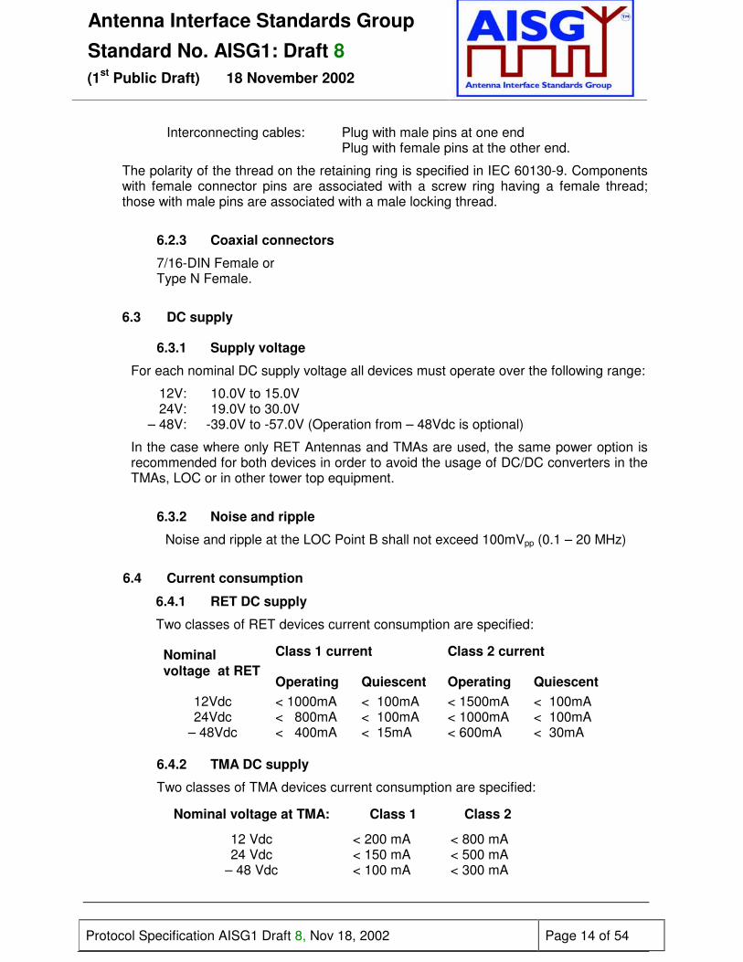
6.2.3 Coaxial connectors
7/16-DIN Female orType N Female.
6.3 DC supply
6.3.1 Supply voltage
For each nominal DC supply voltage all devices must operate over the following range:
12V: 10.0V to 15.0V24V: 19.0V to 30.0V
– 48V: -39.0V to -57.0V (Operation from – 48Vdc is optional)
In the case where only RET Antennas and TMAs are used, the same power option isrecommended for both devices in order to avoid the usage of DC/DC converters in theTMAs, LOC or in other tower top equipment.
6.3.2 Noise and ripple
Noise and ripple at the LOC Point B shall not exceed 100mVpp (0.1 – 20 MHz)
6.4 Current consumption
6.4.1 RET DC supply
Two classes of RET devices current consumption are specified:
Class 1 current Class 2 currentNominalvoltage at RET
Operating Quiescent Operating Quiescent12Vdc < 1000mA < 100mA < 1500mA < 100mA24Vdc < 800mA < 100mA < 1000mA < 100mA
– 48Vdc < 400mA < 15mA < 600mA < 30mA
6.4.2 TMA DC supply
Two classes of TMA devices current consumption are specified:
Nominal voltage at TMA: Class 1 Class 2
12 Vdc < 200 mA < 800 mA24 Vdc < 150 mA < 500 mA
– 48 Vdc < 100 mA < 300 mA

Antenna Interface Standards GroupStandard No. AISG1: Draft 8
(1st Public Draft) 18 November 2002
Protocol Specification AISG1 Draft 8, Nov 18, 2002 Page 15 of 54
6.4.3 ALD network DC supply
DC current supply from a Node-B/BTS to an AISG-specified ALD network isspecified with minimum supplied current and short circuit (s/c) protection maximumcurrent limits:
Nominalnetwork voltage
Class 1 Class 2
Current s/c current Current s/c current12 Vdc > 1200 mA < 3.5 A > 2300 mA < 3.5 A24 Vdc > 950 mA < 3.5 A > 1600 mA < 3.5 A
– 48 Vdc > 500 mA < 3.5 A > 900 mA < 3.5 A
6.4.4 ALD DC Supply Start-up Surge
The power supply must be able to start or restart with a peak and static loadcorresponding to one TMA and one RET as defined below:
ALD (+12Vdc ALD network) Class 1 Class 2RET I peak ( ½ amplitude 0.5ms) 8A 10ATMA I peak ( ½ amplitude 1ms) 0.5A 1.5AStatic load 250mA 900mA
ALD (+24Vdc ALD network) Class 1 Class 2RET I peak ( ½ amplitude 0.5ms) 8A 10ATMA I peak ( ½ amplitude 1ms) 0.5A 1.5AStatic load 200mA 600mA
ALD (– 48Vdc ALD network) Class 1 Class 2RET I peak ( ½ amplitude 1ms) 5A 7ATMA I peak ( ½ amplitude 1ms) 0.4A 1.0AStatic load 115mA 330mA
6.4.5 DC supply via LOC
Figure 6.4.5 shows the arrangement when TMA/LOC is connected to aRET and specifies limiting values for the DC current and voltage at definedpoints..

Antenna Interface Standards GroupStandard No. AISG1: Draft 8
(1st Public Draft) 18 November 2002
Protocol Specification AISG1 Draft 8, Nov 18, 2002 Page 16 of 54
v
Figure 6.4.4: LOC and RET configuration
Assuming RET & TMA Class 1
Point A Point B Point C
Vdc Op mA Q mA Vdc Op mA Q mA Vdc Op mA Q mA
11.0 < 1200 < 100 10.4 < 1000 < 100 10.0 to 15.0 < 1000 < 100
19.7 < 950 < 100 19.2 < 800 < 100 19.0 to 30.0 < 800 < 100
-39.4 < 500 < 30 -39.1 < 400 < 15 -39.0 to –57.0 < 400 < 15
Assuming RET and TMA Class 2
Point A Point B Point C
Vdc Op mA Q mA Vdc Op A Q mA Vdc Op A Q mA
11.6 < 2300 < 150 10.4 < 1500 < 100 10 to 15 < 1500 < 100
20.0 < 1500 < 150 19.2 < 1000 < 100 19 to 30 < 1000 < 100
-39.6 < 900 < 45 -39.1 < 600 < 15 -39 to -57 < 600 < 30
Table 6.4.5: Current and voltage limits for a LOC/RET combination(refer to Fig 6.4.5) Note that the short-circuit and surge current requirements of 6.4.3and 6.4.3 must also be observed.
Node-B/BTS
LayerOneConverterLOC
A
BAIB: RS485 Layer 1
Coaxial Layer 1
AIB volt drop400 mV – 12 V200 mV - 24 V100 mV – 48 V
Loss in LOC.Assumes simplelightning protectionand RF coil giving0.5 ohmimpedance
C
Q mA at point BrepresentsLOC current supply

Antenna Interface Standards GroupStandard No. AISG1: Draft 8
(1st Public Draft) 18 November 2002
Protocol Specification AISG1 Draft 8, Nov 18, 2002 Page 17 of 54
6.4.6 Re-start capability of the power supply at a primary station
The power supply at a primary station and that, if any, at the LOC must be capableof starting normally when the connected devices each draw peak inrush currentsas specified in Table 6.4.4.
6.5 RS485 serial data bus
6.5.1 Connections
The data bus shall be a two wire bi-directional multi-drop configuration conformingto ISO/IEC 8482:1993 (RS485). Pin connections are defined in Para 6.2.1. Theuse of RS485 GND (pin 4) is optional; this connection shall not be used as a DCsupply return.
6.5.2 Device terminating impedance
It is not required for the RS485 to be terminated at the Antenna drive unit. Devicesconnected to the bus should conform to the following parameters:
Resistance between RS485 A and RS485 B > 1k ohmResistance between RS485 A or RS485 Band DC return / RS485 GND > 1k ohmCapacitance between RS485 A and RS485 B < 1nFCapacitance between RS485 A or RS485 Band DC/RS485 GND < 1nF
6.5.3 Bus terminating impedance
An RS485 bus is preferably terminated in an impedance equal to the characteristicimpedance of the cable used to connect bus devices together. Termination may befound to be unnecessary for short connections operating at low data rates and istherefore not mandatory.
6.6 Coaxial interface: modem characteristics
6.6.1 Interference with Existing Systems
The modem must not interfere with existing communications in BTS systems, so aunique carrier frequency for each different communication channel on a commonfeeder cable is necessary. It will be appreciated that each carrier is capable ofsupporting separate logical channels, each of which can support a separateRS485 bus.
Frequencies already known to be in use for proprietary systems are listed inAppendix F of this specification.
The modem circuit must be capable of managing its transmitting characteristic(Para 6.6.6) and providing filtering for its receiver (Para 6.6.7).
The following frequencies (referred to as fo in Fig 6.6.6.2) are specified for futureuse for this application:

Antenna Interface Standards GroupStandard No. AISG1: Draft 8
(1st Public Draft) 18 November 2002
Protocol Specification AISG1 Draft 8, Nov 18, 2002 Page 18 of 54
4.5 MHz +/- 100ppm9.0 MHz +/- 100ppm
6.6.2 Data Rate
The modem shall support the data rates specified in Para 6.7.
6.6.3 Recovery Time
Due to hardware limitations a minimum recovery time must be allowed betweentransmitting and receiving messages on the bus. For this reason a minimumpermitted response time is specified in Paragraph 7.10.3.
6.6.4 Impedance
The modem transceiver shall provide constant impedance in both transmitting andreceiving modes
Nominal impedance Z0: 50 ΩReturn loss at nominal carrier frequency >6dB
6.6.5 Modulation
On-off-keying: Logical 1:Carrier OFF, Logical 0 Carrier ON
6.6.6 Modulator Characteristics
6.6.6.1 Levels
ON-Level: +3 dBm ± 2 dB, OFF-Level: ≤ -40 dBm
6.6.6.2 Spurious Emissions
Spurious emissions shall not exceed the mask shown in figure 6.6.6.2.Intermediate values may be obtained by linear interpolation between the pointsshown.
Figure 6.6.6.2: Spectrum mask for modems
2.5 GHz1000 kHz 50 MHz
+5 dBm
-40 dBm
-25 dBm
-125 dBm
1 MHz
f0
800 kHz
400 MHz
-25 dBm

Antenna Interface Standards GroupStandard No. AISG1: Draft 8
(1st Public Draft) 18 November 2002
Protocol Specification AISG1 Draft 8, Nov 18, 2002 Page 19 of 54
6.6.7 Demodulator Characteristics
The demodulator characteristics have been defined on the assumption of aminimum separation of 2MHz for adjacent carriers on the same coaxial cable. Thismust be taken into consideration when choosing the operating frequency f0.
6.6.7.1 Threshold
Threshold: -15 dBm ± 3 dB
6.6.7.2 Filter Characteristics
Bandwidth ( 3 dB): min. f0 ± 350 kHzBandwidth (25 dB): max. f0 ± 800 kHz
6.6.7.3 Duty Cycle Variation
In order to guarantee proper transmission of data bits through the processes ofmodulation and demodulation, the duty cycle of the received binary data streammay not vary too much from that of the transmitted duty cycle. Specifically thefollowing limit must be met:
∆DCSYSTEM = |DCRX – DCTX| ≤ 10%
Where: ∆DCSYSTEM is the difference between the duty cycles of the transmitted andreceived bit streams,
DCTX = Duty cycle for the input bit stream, andDCRX = Duty cycle for the output bit stream.
Duty cycle for bit stream = tBS/T; duty cycle for OOK = TOOK/T
Figure 6.6.7.3: Duty cycles of the bit stream and OOK modulated subcarrier
“1”
T
“0”
50%
50%
tBS
T
tOOK

Antenna Interface Standards GroupStandard No. AISG1: Draft 8
(1st Public Draft) 18 November 2002
Protocol Specification AISG1 Draft 8, Nov 18, 2002 Page 20 of 54
For transmission through a coaxial cable, two converters are required, one from abit stream to OOK (modulator) and one from OOK back to a bit stream(demodulator), so for each converter half of the total duty cycle tolerance isavailable.
For an input bit stream with a duty ratio of 50%, the cascaded modulator anddemodulator must provide an output bit stream with a duty ratio within the limits40% – 60%, measured in each case at 0.5 times peak amplitude (see Fig 6.4.7.3).
6.7 Data rate & format
6.7.1 Data Rate
The default data rate shall be 9.6kb/s. Higher data rates of 38.4kb/s and 115.2kb/smay optionally be supported. The operating data rate on a bus is established usingthe procedure described in Para 8.4.16.
6.7.2 Data Format
The format of the data shall be:8 data bits No parity1 start bit NRZ-L encoding1 stop bit
6.8 Resumption of operation after interruption of supply
The following provisions apply in the event of complete loss of DC supply orarbitrary reduction of the voltage supplied (brown-out).
6.8.1 Device Type 1 (RET)
Type 1 RETs have electromechanical phase shifters, which require DC power onlyfor control functions. During loss of power antennas with Class 1 RETs continue innormal RF operation but will lose control functionality.
Normal operation shall be resumed after restoration of the power supply after anyinterruption. There shall be no loss of any stored data, including the current set tilt,nor shall there be any change in state such as a change of tilt, self-test or otherautonomous operation.
If power is interrupted during a tilt change operation and as a result the position islost or uncertain, then a PositionLost alarm must be generated on reconnection ofpower.
Type 1 RET systems may be left unpowered for extended periods and will beexpected to resume normal operation as soon as power is applied.
6.8.2 Device Type 2 (TMA)
After restoration of power a TMA shall restart. There shall be no loss of storeddata, including bypass mode or the set gain value (if the TMA supports adjustable

Antenna Interface Standards GroupStandard No. AISG1: Draft 8
(1st Public Draft) 18 November 2002
Protocol Specification AISG1 Draft 8, Nov 18, 2002 Page 21 of 54
gain), nor shall there be any change in state such as a self-test or otherautonomous operation.
6.8.3 Device Type 3 (RET)
Type 3 RETs typically contain phase shifters which rely on continuous DC powerto allow normal RF operation. In the event of the loss of DC power such antennasshall adopt a default status which shall be declared by the manufacturer.
Normal operation shall be resumed after restoration of the power supply after anyinterruption. There shall be no loss of any stored data, including the demanded tiltat the point at which power was interrupted, and any procedures necessary torestore normal operation shall not require the sending of additional commands tothe device.
6.9 Idle-state biasing
The use of idle-state biasing (ISB) is not mandatory, but all ALDs shall be capableof supporting its use. If ISB is implemented then the bias voltages shall be appliedat the primary station.
Reference should be made to TIA/EIA TSB89 for implementation of idle-statebiasing.

Antenna Interface Standards GroupStandard No. AISG1: Draft 8
(1st Public Draft) 18 November 2002
Protocol Specification AISG1 Draft 8, Nov 18, 2002 Page 22 of 54
7 LAYER 2
The data link layer is based on a subset of HDLC which conforms to the requirements ofISO/IEC 13239: 2000. The implementation of this subset is described in Paragraphs 7.1to 7.32 below.
7.1 HDLC Format
7.1.1 Operating Mode
The operating mode shall be normal response mode (NRM) with two wayalternate (TWA) communication. This mode requires that the primary station isalways in control of the bus and the secondary station only answers frames sentby the master. The secondary station cannot send any frame independently.
The channel state shall be start/stop transmission.
7.1.2 Control octet transparency
Control octet transparency shall be implemented in accordance with ISO/IEC13239 Para 4.3.2.2. This requirement applies to all frame types.
7.2 Frame checking sequence (FCS) field
The FCS shall be calculated in accordance with ISO/IEC 13239 on all bytes following thestart flag up to, but not including, the CRC field.
7.3 HDLC Command Sub-set
The protocol shall as a minimum support the following HDLC commands. This commandset is based upon the TWA, UNC (no options) commands list provided in Annex D ofISO/IEC 13239 (UNC15, UNC15.1 and TWA).
Commands(Primary Station)
Responses(Secondary Station)
Frame type I Frame type IFrame type RR Frame type RRFrame type SNRM Frame type UAFrame type DISC Frame type DMFrame type XID Frame type RNR
Frame type FRMR(optional)
Table 7.3: Frame types implemented in this standard

Antenna Interface Standards GroupStandard No. AISG1: Draft 8
(1st Public Draft) 18 November 2002
Protocol Specification AISG1 Draft 8, Nov 18, 2002 Page 23 of 54
7.3.1 I-frame and INFO-field format
The I-frame and INFO-field formats for both primary and secondary stations shallbe as illustrated in Table 7.3.1. INFO-fields are only used with I-frames.
The Frame Control Field shall be formatted in accordance with ISO/IEC 13239Para 5.3.1, Table 3.
HDLC-Frame:Flag8bit
ADR8bit
Control8bit
INFON x 8bit
CRC2 x 8bit
Flag8bit
0x7E DeviceAddress
Controlbits
Variable length(must support a maximumlength of at least 74 bytes)
CRC1lowbyte
CRC2highbyte
0x7E
AISG Command ID Number ofdata bytes Data bytes
Version ID 1 byte lowbyte
highbyte
Variable length(must support a maximumlength of at least 70 bytes)
.Table 7.3.1: Format of the I-Frame and INFO Field
Devices shall support the following data length:
Mandatory: 0 ≤ data bytes ≤ 70Optional: 0 ≤ data bytes < 65,535 bytes
7.3.2 Version ID
The version ID shall be used to identify the version of the AISG Layer 7 instructionset supported by the secondary station. It shall be set as 0x01 for equipmentconforming to the first formal issue (Issue 1) of this specification.
7.4 HDLC Address
The HDLC address shall be stored in non-volatile memory and restored on power-up. Thesecondary station compares its own address with the Address field of the received framesfrom the bus. If the addresses are equal the frame is accepted and will be processed.
There is no response from secondary stations to broadcast addresses.
Two addresses are reserved for device management, these are:
7.4.1 Address 0x00
Address 0x00 is the initial state during installation. It is recommended that alldevices be assigned this address by the manufacturer prior to shipment to thecustomer unless otherwise agreed by prior arrangement.

Antenna Interface Standards GroupStandard No. AISG1: Draft 8
(1st Public Draft) 18 November 2002
Protocol Specification AISG1 Draft 8, Nov 18, 2002 Page 24 of 54
7.4.2 Address 0xFF
Address 0xFF is a broadcast address. All devices connected shall processcommands received via a broadcast.
7.4.3 Address configuration
Before communication can be established on a bus it is necessary to configure theaddresses of the devices connected to it. Address assignment is mediated by theuse of an XID frame carrying data fields as specified in ISO 13239 Para 5.5.3.
7.4.3.1 Address Assignment Command
The format of the XID frame originated by the primary station shall be as follows:
Field Content Description
ADDR 0xFF BroadcastCTRL XID CommandFI 0x81 Format identifierGI 0xF0 User defined parameter setGL n+5 Length of parameter fieldPI 1 Parameter id 1 = unique idPL n Length of PV field in bytesPV unique ID Vendor id/serial number (n bytes)*PI 2 Parameter id 2 = addressPL 1 Length of PV field in bytesPV 1 – 254 Assigned address
*The serial number is right aligned and any leading blanks are padded with zeros(0x00).
7.4.3.2 Address Assignment Response
The secondary verifies FI, GI, GL and PI, PL for the two parameters. It thenchecks the first PV to see if it contains the its own unique ID. If so it changes itsaddress to the one supplied in the second PV. It then responds with a UA frametransmitted from its new address.
Field Content DescriptionADDR # Device addressCTRL UA Command
If the first PV does not match its unique ID, but the secondary already uses theaddress specified in the second PV, it changes its address to zero in order toremove itself from the bus. This prevents a situation in which two devices have thesame address.
If neither the first PV nor the second PV matches, the secondary does nothing.
After the assignment of its address a secondary remains in the disconnectedstate.
Antenna Interface Standards GroupStandard No. AISG1: Draft 8
(1st Public Draft) 18 November 2002
Protocol Specification AISG1 Draft 8, Nov 18, 2002 Page 25 of 54
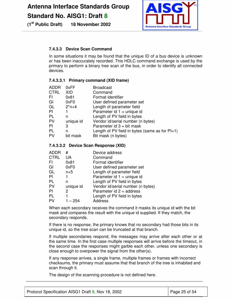
7.4.3.3 Device Scan Command
In some situations it may be found that the unique ID of a bus device is unknownor has been inaccurately recorded. This HDLC command exchange is used by theprimary to perform a binary tree scan of the bus, in order to identify all connecteddevices.
7.4.3.3.1 Primary command (XID frame)
ADDR 0xFF BroadcastCTRL XID CommandFI 0x81 Format identifierGI 0xF0 User defined parameter setGL 2*n+4 Length of parameter fieldPI 1 Parameter id 1 = unique idPL n Length of PV field in bytesPV unique id Vendor id/serial number (n bytes)PI 3 Parameter id 3 = bit maskPL n Length of PV field in bytes (same as for PI=1)PV bit mask Bit mask (n bytes)
7.4.3.3.2 Device Scan Response (XID)
ADDR # Device addressCTRL UA CommandFI 0x81 Format identifierGI 0xF0 User defined parameter setGL n+5 Length of parameter fieldPI 1 Parameter id 1 = unique idPL n Length of PV field in bytesPV unique id Vendor id/serial number (n bytes)PI 2 Parameter id 2 = addressPL 1 Length of PV field in bytesPV 1 – 254 Address
When each secondary receives the command it masks its unique id with the bitmask and compares the result with the unique id supplied. If they match, thesecondary responds.
If there is no response, the primary knows that no secondary had those bits in itsunique id, so the tree scan can be truncated at that branch.
If multiple secondaries respond, the messages may arrive after each other or atthe same time. In the first case multiple responses will arrive before the timeout, inthe second case the responses might garble each other, unless one secondary isclose enough to overpower the signal from the other(s).
If any response arrives, a single frame, multiple frames or frames with incorrectchecksums, the primary must assume that that branch of the tree is inhabited andscan through it.
The design of the scanning procedure is not defined here.

Antenna Interface Standards GroupStandard No. AISG1: Draft 8
(1st Public Draft) 18 November 2002
Protocol Specification AISG1 Draft 8, Nov 18, 2002 Page 26 of 54
7.5 Window Size (minimum)
The minimum window size is 1.
7.6 Connection Establish
The primary station sends an SNRM-frame to the secondary station. The secondarystation responds with a UA-frame, its message buffers are emptied, HDLC sequencenumbers are re-set and it enters the connected state. After the primary station receivesthe UA-frame, the corresponding secondary station is administered as connected.
7.7 Disconnect
The primary station sends a DISC-frame to the secondary station. The secondary stationresponds with a UA-frame and enters the disconnected state. After the primary stationreceives the UA-frame, the corresponding secondary station is administered asdisconnected.
If the secondary station is in disconnected mode, it shall respond as defined in ISO 13239Para 5.2.2.1.
7.8 Polling
Before any secondary station can be polled, it must first be placed in the connected state(Para 7.6). The primary station polls at time intervals as defined in paragraph 7.10.1.
On reception of a frame with correct FCS and matching address and with the poll-bit set,the secondary station is required to transmit frames on the bus within the times defined inPara 7.10.2.
If the secondary station has an I-frame to transmit it shall do so. If it does not have an I-frame to transmit it shall respond with either an RR or RNR frame If it is unable to receiveI-frames, for instance because it has run out of empty buffers, it shall respond with RNR.Otherwise it shall respond with RR. Please study Appendix B in Reference 13 for moredetails.
This polling procedure provides layer 7 with a full-duplex link, allowing layer 7 tospontaneously transmit messages, such as alarm messages. (For details of the layer 7alarm messages, please refer to Para 8.4.6).
If the secondary does not receive a poll within 3 minutes of the previous poll, it mayoptionally perform a reset.
In the event that the primary station receives no responses from a secondary station, it isrecommended that it signals loss of connection to its master.
7.9 Information
Before any secondary station can be required to send or receive an I-frame, it must firstbe placed in the connected state (Para 7.6). One I-frame is used for one message, sofragmentation is not required. If the primary station sends a command to the secondary

Antenna Interface Standards GroupStandard No. AISG1: Draft 8
(1st Public Draft) 18 November 2002
Protocol Specification AISG1 Draft 8, Nov 18, 2002 Page 27 of 54
station, one I-frame is generated and sent. The secondary station can respond with anyvalid HDLC response belonging to the subset implemented in this standardd.
7.10 Message timing
7.10.1 Primary Station Poll
Each secondary station shall be polled at the following intervalsMinimum 300msMaximum 1 minute
7.10.2 Secondary Station Frame response
The primary station should receive a complete response frame within 10ms plusthe time taken for the transmission of 100 bytes from the time the final flag byte istransmitted. The secondary station should start to transmit a response within10ms. The time occupied by the transmission of 100 bytes allows time-outs toinclude transmission time, with 10ms allowed for processing.
7.10.3 Message timing
A minimum of 3ms must elapse between transmitting and receiving messages ona bus.
7.11 Frame Error Rate
The number of frames detected with incorrect checksums shall be less than 1frame in 5000 frames.

Antenna Interface Standards GroupStandard No. AISG1: Draft 8
(1st Public Draft) 18 November 2002
Protocol Specification AISG1 Draft 8, Nov 18, 2002 Page 28 of 54
8 LAYER 7
8.1 Command Format
Apart from address configuration, which uses the XID frame, commands to devices aretransmitted within the HDLC INFO-field. The general format for all commands is thefollowing:
Command Number of data bytes Data bytes1 byte 2 bytes max 70 bytes (basic implementation)
8.2 Response format and return codes
All responses from devices are transmitted in the HDLC INFO field. The general format forall responses is the following:
Command Number of data bytes Data bytes1 byte 2 bytes max 70 bytes (basic implementation)
The maximum time for all responses shall be 1 second unless specified in the individualcommand. Tilt setting, calibration and self test will typically require a longer period forcompletion of the command.
One or more return codes are transmitted in the data bytes.
A complete annotated table of all available return codes with their correspondinghexadecimal numbers is provided in Appendix C of this specification.
8.3 Overview of commands
This standard provides for a set of command-oriented instructions and also provides facilitiesto read and write data to specified locations in the memory of the secondary stations.
Global Commands Commandnumber
Global Commands Commandnumber
(Reserved) 0x01 Disable Device 0x09
Get Device Type 0x02 Self Test 0x0A
Reset 0x03 Read Memory 0x0B
Get Error Status 0x04 Write Memory 0x0C
Get H/W & S/W Info 0x05 Get Supported Bit Rates 0x0D
Clear Alarms 0x06 Set Device Data 0x0E
Alarm 0x07 Get Device Data 0x0F
Enable Device 0x08
Table 8.3a: Mandatory global commands

Antenna Interface Standards GroupStandard No. AISG1: Draft 8
(1st Public Draft) 18 November 2002
Protocol Specification AISG1 Draft 8, Nov 18, 2002 Page 29 of 54
Optional commands
Software Downloadcommand sequence: Command number
Download Start 0x2E
Store Data Start 0x20
Store Data Block Seg 0x21
Download End 0x22
Set Bit Rate 0x24
Table 8.3b: Optional global commands
Device specific commands (RET)
Command Command number
Calibrate 0x31
Send Config data 0x32
Set Tilt 0x33
Get Tilt 0x34
Table 8.3c: RET-specific commands
Device specific commands (TMA)
Command Command number
Set TMA Mode 0x40
Get TMA Mode 0x41
Set TMA Gain 0x42
Get TMA Gain 0x43
Table 8.3d: TMA-specific commands
8.3e Vendor specific commands: Command number 0xFF(see Para 8.9 for implementation)

Antenna Interface Standards GroupStandard No. AISG1: Draft 8
(1st Public Draft) 18 November 2002
Protocol Specification AISG1 Draft 8, Nov 18, 2002 Page 30 of 54
8.4 Global Command Interface – Mandatory for all Devices
In order to achieve interoperability, the following defined commands must be implemented ineach antenna-line device. RETs, TMAs and other antenna-line devices attached to theRS485 bus are designated as secondary stations, which must all support following thecommands.
In response to all layer-7 commands from the primary station, the addressed secondarystation shall respond with <OK> whenever a normal outcome to the command has resulted,and <FAIL> otherwise. Additional parameters may be associated with the response <OK>and a variety of defined return codes (error messages) with the response <FAIL> asdescribed in the following paragraphs. Return codes are also used as autonomous alarmresponses (see Para 8.4.7 for details). A summary table and interpretation of all definedreturn codes is provided in Appendix C. When return codes are used, they shall havemeanings consistent with those described. Some return codes are common to all devicetypes; others are specific to a particular device type.
All alphanumeric fields shall use ASCII characters, using the character set defined in Section5 of this specification.
A primary station (any control equipment, Node-B, &c) must execute two procedures foreach secondary station (RET, TMA, &c) before control of the secondary station is possible:
1. The HDLC address must be assigned to the secondary station, and2. The device type of the secondary station must be requested, so the primary can
identify the appropriate command set to with which to communicate with thesecondary device.
8.4.1 Get Device TypeCommand Name: GetDevType
This command requests the type of a network device. A scan of all correctlyconfigured and connected devices connected to the RS485 bus may be initiated bysending the command GetDevType to each address and evaluating the responses.
Data field command to secondary station:0x02 0x00 0x00
Data field response from secondary station:0x02 <LengthLowByte> <LengthHighByte> <OK> <VendorLowByte> ..<VendorHighByte> <DeviceType>
Vendor codes and device types are defined in Appendix A and B respectively.
Data field response from secondary station in case of error in performing thecommand:0x02 <LengthLowByte><LengthHighByte><FAIL> <ReturnCode1>..<ReturnCodeN>
Antenna Interface Standards GroupStandard No. AISG1: Draft 8
(1st Public Draft) 18 November 2002
Protocol Specification AISG1 Draft 8, Nov 18, 2002 Page 31 of 54
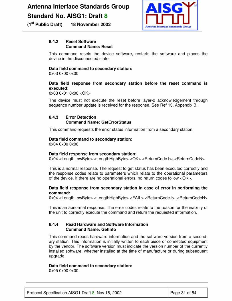
8.4.2 Reset SoftwareCommand Name: Reset
This command resets the device software, restarts the software and places thedevice in the disconnected state.
Data field command to secondary station:0x03 0x00 0x00
Data field response from secondary station before the reset command isexecuted:0x03 0x01 0x00 <OK>
The device must not execute the reset before layer-2 acknowledgement throughsequence number update is received for the response. See Ref 13, Appendix B.
8.4.3 Error DetectionCommand Name: GetErrorStatus
This command requests the error status information from a secondary station.
Data field command to secondary station:0x04 0x00 0x00
Data field response from secondary station:0x04 <LengthLowByte> <LengthHighByte> <OK> <ReturnCode1>..<ReturnCodeN>
This is a normal response. The request to get status has been executed correctly andthe response codes relate to parameters which relate to the operational parametersof the device. If there are no operational errors, no return codes follow <OK>.
Data field response from secondary station in case of error in performing thecommand:0x04 <LengthLowByte> <LengthHighByte> <FAIL> <ReturnCode1>..<ReturnCodeN>
This is an abnormal response. The error codes relate to the reason for the inability ofthe unit to correctly execute the command and return the requested information.
8.4.4 Read Hardware and Software InformationCommand Name: GetInfo
This command reads hardware information and the software version from a second-ary station. This information is initially written to each piece of connected equipmentby the vendor. The software version must indicate the version number of the currentlyinstalled software, whether installed at the time of manufacture or during subsequentupgrade.
Data field command to secondary station:0x05 0x00 0x00

Antenna Interface Standards GroupStandard No. AISG1: Draft 8
(1st Public Draft) 18 November 2002
Protocol Specification AISG1 Draft 8, Nov 18, 2002 Page 32 of 54
Data field response from secondary station:0x05 <LengthLowByte> <LengthHighByte> <OK> <Length> <ProdNr> <Length ><SerNo> <Length > <HWVersion> <Length> <SWVersion>
ProdNr is the product type number and SerNr is the unique serial number of theindividual unit.
HWVersion and SWVersion refer to the version designators of the hardware andinstalled software of the secondary station. If the application is missing or no versionnumber is found, then an empty string shall be returned as the version number.
Data field response from secondary station in case of error in performing thecommand0x05 <LengthLowByte> <LengthHighByte> <FAIL> <ReturnCode1>..<ReturnCodeN>
8.4.5 Clear stored AlarmsCommand Name: ClearAlarms
This command clears alarm information which is stored in the secondary station.
Data field command to secondary station:0x06 0x00 0x00
Data field response from secondary station after clearing the alarm flags:0x06 0x01 0x00 <OK>
Data field response from secondary station in case of error in performing thecommand0x06 <LengthLowByte> <LengthHighByte> <OK> <ReturnCode1> .. <ReturnCodeN>
8.4.6 Poll response from Secondary StationResponse Name: Alarm
Layer 2 provides a virtual full-duplex link to layer 7 (see Para 7.8). This virtual full-duplex link is used to simplify alarm reporting.
The secondary station report every change in error status by transmitting alarmmessage in response to a poll. Formally this is a response message, even though(on layer 7) it is a spontaneous message. There is no layer 7 command to request analarm response message.
The alarm message contains a list of error-code/state-flag pairs. The state flagindicates that the error has occurred (StateFlag = 1) or cleared (StateFlag = 0).
Only error codes whose state has changed shall be included in the list. Thesecondary station may group several error codes into one message, but theirsequence in the message must then reflect the sequence in which they occurred.
A rapid setting/clearing sequence of the same alarm may be reported in the samealarm message in the order in which they occurred (FIFO).

Antenna Interface Standards GroupStandard No. AISG1: Draft 8
(1st Public Draft) 18 November 2002
Protocol Specification AISG1 Draft 8, Nov 18, 2002 Page 33 of 54
In the event that the rapid state changes cause overflow of the available buffers, theoldest error code changes shall be discarded and the later ones retained fortransmission.
Autonomous data field response from secondary station if an error state haschanged since the previous poll from the primary station:0x07 <LengthLowByte><LengthHighByte><ReturnCode1><StateFlag1>….…<ReturnCodeN> <StateFlagN>
Alarm return codes are defined in Appendix C.
8.4.7 Enable DeviceCommand Name: Enable
This command enables a device (secondary station) for operation. If a device isenabled, all commands are executable; if it is already enabled, a second enablecommand will be accepted without error and the device will remain enabled.Internally, the status of the device is always set to enabled after the command isreceived.
Data field command to secondary station:0x08 0x00 0x00
Data field response from secondary station in case of no error:0x08 0x01 0x00 <OK>
Data field response from secondary station in case of error in performing thecommand:0x08 <LengthLowByte> <LengthHighByte> <FAIL> <ReturnCode1>..<ReturnCodeN>
8.4.8 Disable DeviceCommand Name: Disable
This command secures devices against unauthorised or accidental change ofoperational parameters. When a device is disabled, commands which SETparameters will not be accepted and an DeviceDisabled error will be returned. If it isalready disabled, a second disable command will be accepted without error and thedevice will remain disabled. Internally, the status of the device is always set todisabled after the command is received.
All devices shall be delivered by vendors with their status set to 'disabled'. The statusof every device after reset shall default to 'disabled'. Following a power failure thestatus of any device shall be unchanged after restoration of power.
Data field command to secondary station:0x09 0x00 0x00
Data field response from secondary station in case of no error:0x09 0x01 0x00 <OK>

Antenna Interface Standards GroupStandard No. AISG1: Draft 8
(1st Public Draft) 18 November 2002
Protocol Specification AISG1 Draft 8, Nov 18, 2002 Page 34 of 54
Data field response from secondary station in case of error in performing thecommand:0x09 <LengthLowByte> <LengthHighByte> <FAIL> <ReturnCode1>..<ReturnCodeN>
8.4.9 Self TestCommand Name: SelfTest
This command executes a test function at the device which may include a check ofphysical and processor functions.
The response from the command provides the user with information on detectedfaults or, if no fault is detected, with confidence that the operation of the device isnormal in all respects.During the test the operational parameters of the device shall not change beyondoperationally acceptable limits and on completion all parameters shall be returned totheir initial values.
Data field command to secondary station:0x0A 0x00 0x00
Data field response from secondary station:0x0A <LengthLowByte><LengthHighByte><OK><ReturnCode1>..<ReturnCodeN>
This is a normal response in which the self test was executed with return codes set toreport possible detected functional errors during the test. If no errors are detected,this shall be signalled by no return codes following <OK>.
Data field response from secondary station in case of error in performing thecommand:0x0A <LengthLowByte><LengthHighByte><FAIL><ReturnCode1>..<ReturnCodeN>
In this case the self test could not be executed and the return codes relate to theinability of the device to perform the requested self-test operation.
8.4.10 Read and Write Memory
8.4.10.1 Read MemoryCommand name: ReadMemory
Data field command to secondary station:0x0B <LengthLowByte> <LengthHighByte> <MemoryAddressByte1><MemoryAddressByte2> < MemoryAddressByte3> < MemoryAddressByte4><n = number of bytes to read>
Data field response from secondary station in case of no error:0x0B <LengthLowByte><LengthHighByte><OK> <MemoryAddressByte1><MemoryAddressByte2> < MemoryAddressByte3> < MemoryAddressByte4><byte1> ... <byteN>

Antenna Interface Standards GroupStandard No. AISG1: Draft 8
(1st Public Draft) 18 November 2002
Protocol Specification AISG1 Draft 8, Nov 18, 2002 Page 35 of 54
Data field response from secondary station in case of error:0x0B <LengthLowByte> <LengthHighByte> <FAIL> <Return Code (s)>
8.4.10.2 Write MemoryCommand name: WriteMemory
Data field command to secondary station:0x0C <LengthLowByte><LengthHighByte><OK> <MemoryAddressByte1><MemoryAddressByte2> < MemoryAddressByte3> .. < MemoryAddressByte4><byte1> ... <byteN>
Data field response from secondary station in case of no error0x0C 0x01 0x00 <OK>
Data field response from secondary station in case of error0x0C <LengthLowByte> <LengthHighByte> <FAIL> <ReturnCode1> <ReturnCodeN>
8.4.11 Get supported bit ratesCommand Name: GetBitRates
This command is used to determine which bit rates are supported by anydevice connected to a bus. All systems shall respond to this command, butsupport for bit rates other than 9.6kb/s is optional. Devices which supportmultiple bit rates will reply with multiple values.
Data field command to secondary station:0x0D 0x00
Data field response from secondary station in case of no error:0x0D 0x04 0x00 <OK> < BitRateByte1> < BitRateByte2> < BitRateByte3>
Bit rate byte:0x00 : 9.6kb/s0x01 : 38.4kb/s0x02 : 115.2kb/s
Data field response from secondary station in case of error:0x0D <LengthLowByte> <LengthHighByte> <FAIL> <ReturnCode1>..<ReturnCodeN>
8.4.12 Set Device DataCommand name: SetDeviceData
This command is used to write data into the fields optionally provided forconfiguration data and listed in Appendix D. If an attempt is made to write to fieldswhich are not supported by a particular device, no error is returned but the data forthose fields is ignored.

Antenna Interface Standards GroupStandard No. AISG1: Draft 8
(1st Public Draft) 18 November 2002
Protocol Specification AISG1 Draft 8, Nov 18, 2002 Page 36 of 54
Data field command to secondary station:0x0E <LengthLowByte><LengthHighByte><0x01><data bytes for parameter 1><0x02> <data bytes for parameter 2> <0x03><data bytes for parameter 3>… <0x0N>< data bytes for parameter N>
Data field response from secondary station in case of no error:0x0E 0x01 0x00 <OK>
Data field response from secondary station in case of error:0x0E <LengthLowByte><LengthHighByte><FAIL> <ReturnCode1>...<ReturnCodeN>
8.4.13 Get Device DataCommand Name: GetDeviceData
This command is used to read data stored in the fields optionally provided forconfiguration data and listed in Appendix D. If an attempt is made to read fields whichare not supported by a particular device no data is returned for that field. Thecommand contains a list of the field numbers of those fields whose contents are to bereturned in the response from the secondary station. The field numbers are notnecessarily contiguous or ordered.
Data field command to secondary station:0x0F <LengthLowByte><LengthHighByte><0x01 <0x02> <0x03> … <0x0N>
Data field response from secondary station in case of no error:0x0F <LengthLowByte><LengthHighByte> <OK> <0x01><data bytes for parameter1> <0x02> <data bytes for parameter 2> <0x03><data bytes for parameter 3>…<0x0N> < data bytes for parameter N>
Data field response from secondary station in case of error:0x0F <LengthLowByte><LengthHighByte><FAIL> <ReturnCode1>...<ReturnCodeN>
8.4.14 Software Download (Optional feature)
If software download is supported, then the following commands are used todownload new software releases to a secondary station. The sequence of thefollowing commands must be strictly observed. After the complete sequence a resetcommand is necessary to activate the new software.
For implementations in which more than one software data file will be downloaded toa secondary station, the address of the memory locations to be erased shall betransmitted in the header of the first data block of each data file.
The sequence of commands to effect a software download to a secondary station isillustrated in Appendix E of this standard.

Antenna Interface Standards GroupStandard No. AISG1: Draft 8
(1st Public Draft) 18 November 2002
Protocol Specification AISG1 Draft 8, Nov 18, 2002 Page 37 of 54
8.4.14.1 Download StartCommand Name: DownloadStart
This command initiates internal copy and execution of software routines and maydelete parts of the flash memory. An <OK> response indicates that any flash erasurehas been successfully executed.
Data field command to secondary station:0x2E 0x00 0x00
Data field response from secondary station in case of no error:0x2E 0x01 0x00 <OK>
Data field response from secondary station in case of error:0x2E <LengthLowByte> <LengthHighByte> <FAIL><ReturnCode1>.<ReturnCodeN>
8.4.14.2 Store Data StartCommand Name: StoreDataStart
This command specifies the block-number of the block which will be transferred andthe number of bytes within this block.
Data field command to secondary station:0x020 0x04 0x00 <BlockNrLSB> <BlockNrMSB> <BlockLengthLSB><BlockLengthMSB>
Data field response from secondary station in case of no error:0x20 0x03 0x00 <OK> <BlockNrLSB> <BlockNrMSB>
Data field response from secondary station in case of error:0x20 <LengthLowByte> <LengthHighByte> <FAIL> <BlockNrLSB> <BlockNrMSB><ReturnCode1> ... <ReturnCodeN>
8.4.14.3 Store Data Block SegmentCommand Name: StoreDataBlockSeg
This command transfers data segments to the secondary station.
Data field command to secondary station:0x21 <LengthLowByte> <LengthHighByte> <SegmentNumber> <data 1>...<data n>(comment: nmax = 64 if 70-byte I-fields are used)
Data field response from secondary station in case of no error:0x21 0x02 0x00 <OK> <SegmentNumber>
Data field response from secondary station in case of error:0x21 <LengthLowByte> <LengthHighByte> <FAIL> <SegmentNumber><ReturnCode1> ... <ReturnCodeN>

Antenna Interface Standards GroupStandard No. AISG1: Draft 8
(1st Public Draft) 18 November 2002
Protocol Specification AISG1 Draft 8, Nov 18, 2002 Page 38 of 54
The segment number commences at 0 and is incremented in steps of 1 to amaximum value of 255. If more than 256 segments are required, a new block mustbe started which in turn resets the segment number to 0.
8.4.14.4 Download EndCommand Name: DownloadEnd
With this command the primary station signals the end of software transfer to thesecondary station. The secondary responds after verifying the checksum of the datatransferred to memory.
Data field command to secondary station:0x22 0x00 0x00
Data field response from secondary station in case of no error:0x22 0x01 0x00 <OK>
Data field response from secondary station in case of no error:0x22 <LengthLowByte> <LengthHighByte> <FAIL> <ReturnCode1>.<ReturnCodeN>
8.4.15 Optional command: Set Bit RateCommand name: SetBitRate
This broadcast command informs all connected secondary stations that the primaryhas been ordered to switch to the specified bit rate. The message shall not berepeated.
Data field command to secondary stations:<0x27> <bit rate byte>
Bit rate byte:0x00 : 9.6kb/s0x01 : 38.4kb/s0x02 : 115.2kb/s
There is no response from secondary stations to this broadcast command until 5further frames have been received.
8.4.15.1 Bit rate change procedure
It is mandatory that any secondary station that supports multiple bit rates is capableof supporting this procedure.
The primary station is not allowed to change the bit rate autonomously; it willgenerally be set during system configuration, or as an operator-mediated response toa communications failure, perhaps caused by physical damage to the bus. Secondarystations will operate at the specified bit rate and will check briefly for communicationat other bit rates only if the bus has been quiet for a long period. The system providesa stable and reliable bit rate fallback scheme.
A secondary station that supports bit rates other than the mandatory 9.6kb/s musthave a 1-minute LineIsDead timeout. This timeout must be re-set whenever the

Antenna Interface Standards GroupStandard No. AISG1: Draft 8
(1st Public Draft) 18 November 2002
Protocol Specification AISG1 Draft 8, Nov 18, 2002 Page 39 of 54
secondary receives a valid HDLC frame, regardless of its address. It must also havea FramingError counter and a BytesReceived counter. Both these counters must bereset to zero whenever a valid HDLC frame is received, regardless of its address.
As all devices support a bit rate of 9.6kb/s, communication can be established on thebus before a higher rate is set. The primary should first use the GetBitRatescommand to determine which higher bit rate(s) can be supported by all connecteddevices, as the maximum bus bit rate is determined by the slowest connected device.The primary is then set to operate at the new bit rate. It may be preferred to send aSetBitRate command before the primary rate is changed; this makes the subsequentprocedure at the secondary stations faster but its use is optional.
If the LineIsDead timeout occurs at a secondary station its current bit rate is assumedto be invalid and the secondary shall initiate the bit rate test sequence as follows:
1. Set the bit rate to the maximum supported rate;2. Clear the FramingError and BytesReceived counters;3. Wait 10 seconds, or until a valid HDLC frame is received;4. If any valid HDLC frame is received (regardless of its address) the sequence is
terminated, but the bit rate is not stored until 5 further frames (regardless oftheir address) have been received;
5. If the FramingError and BytesReceived counters are zero, the bit rate isrestored to the last stored bit rate and the sequence is terminated;
6. If the FramingError counter is at least 10 or the BytesReceived counter is atleast 10 the bit rate is assumed to be wrong. If the bit rate is greater than9.6kb/s the bit rate is reduced and the sequence continues with Step 2.
7. If the bit rate is already 9.6kb/s the bit rate is restored to the last stored bit rateand the sequence is terminated.
8.5 Device Specific Commands for a RET
8.5.1 RET CalibrationCommand Name: Calibrate
This command is sent after installation of a RET. Calibration entails ensuring that theactuator is driven through its whole tilt range.
After reset or power failure no calibration is normally required. There may occasion-ally be unforeseen errors where calibration could be required to return the RET to acorrect no-error status.
Data field command to secondary station:0x31 0x00 0x00
Data field response from secondary station in case of no error:0x31 0x01 0x00 <OK>
Data field response from secondary station in case of error:0x31 <LengthLowByte> <LengthHighByte> <FAIL> <ReturnCode1>..<ReturnCodeN>

Antenna Interface Standards GroupStandard No. AISG1: Draft 8
(1st Public Draft) 18 November 2002
Protocol Specification AISG1 Draft 8, Nov 18, 2002 Page 40 of 54
8.5.2 RET Send Configuration DataCommand Name: SendConfigData
This command may be required after installation of any RET unless alreadyperformed by the vendor before delivery. It loads vendor and antenna specificconfiguration data to establish the relationship between the movement of the drivesystem and the beam tilt position of the antenna.
When specified by the vendor the data must be loaded during the installationprocedure. (Typically this may be necessary because the same type of drive unit(RET) may be used in association with different antenna types, each requiringdifferent configuration data.)
Data field command to secondary station:0x32 <LengthLowByte> <LengthHighByte> <DataByte1> ... <DataByteN>
Data field response from secondary station in case of no error:0x32 0x01 0x00 <OK>
Data field response from secondary station in case of error:0x32 <LengthLowByte> <LengthHighByte> <FAIL> <ReturnCode1>..<ReturnCodeN>
8.5.3 RET Set TiltCommand Name: SetTilt
This command sets the electrical tilt value in increments of 0.1°.
The response time shall be less than 2 minutes.
The format of the demanded tilt shall be a 16 bit signed number. (See Section 5 fordefinition and sign convention.)
Data field command to secondary station:0x33 0x02 0x00 <TiltLowByte> <TiltHighByte>
Tilt values are specified in 0.1° increments starting from zero, for example: Tilt 3.2° is0x0020 (stored as <0x20>< 0x00>), Tilt − 3.2° is 0xFFE0, stored as <0xE0><0xFF>).
Data field response from secondary station in case of no error:0x33 0x01 0x00 <OK>
Data field response from secondary station in case of error:0x33 <LengthLowByte> <LengthHighByte> <FAIL> <ReturnCode1> ...<ReturnCodeN>
8.5.4 RET Get TiltCommand Name: GetTilt
This command requests the current tilt value.The response is made in increments of 0.1° in the format specified in Para 8.5.3.

Antenna Interface Standards GroupStandard No. AISG1: Draft 8
(1st Public Draft) 18 November 2002
Protocol Specification AISG1 Draft 8, Nov 18, 2002 Page 41 of 54
Data field command to secondary station:0x34 0x00 0x00
Data field response from secondary station in case of no error0x34 0x03 0x00 <OK> <TiltLowByte> <TiltHighByte>
Data field response from secondary station in case of error0x34 <LengthLowByte> <LengthHighByte> <FAIL> <ReturnCode1>..<ReturnCodeN>
8.6 Specific commands for a TMA
The TMA MODE commands are applicable to TMAs that support bypass.The TMA GAIN commands are applicable to TMAs that support variable gain.
8.6.1 Set TMA ModeCommand name: SetMode
This command switches a TMA into and out of bypass mode. In bypass mode asuitable switch bypasses the amplifiers.
If a mode is already set, the command to set the mode will be accepted without anerror and the TMA will remain in the specified mode.
Data field command to secondary station:0x50 0x01 0x00 0x00 Set normal mode0x50 0x01 0x00 0x01 Set bypass mode
Data field response from secondary station in case of no error:0x50 0x01 0x00 <OK>
Data field response from secondary station in case of no error:0x50 <LengthLowByte> <LengthHighByte> <FAIL><ReturnCode1>…<ReturnCodeN>
8.6.2 GET TMA MODE
Command Name: GetMode
This command requests the error status information from a secondary station.
Data field command to secondary station:0x51 0x00 0x00
Data field response from secondary station:0x51 0x02 0x00 <OK> 0x00 TMA in bypass mode0x51 0x02 0x00 <OK> 0x01 TMA in normal mode
Data field response from secondary station in case of error:0x51 <LengthLowByte> <LengthHighByte> <FAIL> <ReturnCode1>…<ReturnCodeN>

Antenna Interface Standards GroupStandard No. AISG1: Draft 8
(1st Public Draft) 18 November 2002
Protocol Specification AISG1 Draft 8, Nov 18, 2002 Page 42 of 54
8.6.3 Set TMA GainCommand Name: SetGain
This command sets the gain of a TMA in increments of 0.5dB.
The format of the demanded gain shall be an 8 bit unsigned number. The number shallbe calculated from zero dB (0x00) in increments of 0.5dB.
If the gain parameter is out of the available range, the gain remains unchanged andthe TMA returns an error code (GainOutOfRange)
Data field command to secondary station:0x52 0x00 0x01 <Gain>
Data field response from secondary station in case of no error:0x52 0x01 0x00 <OK>
Data field response from secondary station in case of no error:0x52<LengthLowByte><LengthHighByte><FAIL><ReturnCode1>…<ReturnCodeN>
8.6.4 Get TMA GainCommand Name: GetGain
This command gets the gain of the TMA in increments of 0.5dB.
The format of the gain shall be an 8 bit unsigned number. The number shall becalculated from zero dB (0x00) in increments of 0.5dB.
Data field command to secondary station:0x53 0x00 0x00
Data field response from secondary station in case of no error:0x53 0x00 0x02 <OK> <Gain>
Data field response from secondary station in case of error:0x53 <LengthLowByte> <LengthHighByte> <FAIL> <ErrorCode1>…<ErrorCodeN>
8.7 Vendor Specific Commands
These commands which are vendor specific are internally implemented but are not used forcontrol or telemetry functions. These commands are used for test and development, and arenot published. All control and telemetry functions shall be accomplished using thecommands specified in this standard.
Vendor Specific Commands and responses shall be formatted as follows:0xFF <LengthLowByte> <LengthHighByte> <VendorID> ( …remaining format and contentvendor specific.)

Antenna Interface Standards GroupStandard No. AISG1: Draft 8
(1st Public Draft) 18 November 2002
Protocol Specification AISG1 Draft 8, Nov 18, 2002 Page 43 of 54
8.8 Unknown Commands
If a secondary station is unable to recognise a command, the secondary station shallrespond as follows:
INFO field command to secondary station:<UnknownCommand> <LengthLowByte> <LengthHighByte> <Data1> ... <DataN>
INFO field response from secondary station:<unknown command> 0x02 0x00 <FAIL> <ReturnCode>
8.9 Additional commands for control and telemetry
Members of AISG may at any time request the registration of additional commands,responses and parameters to manage control and telemetry functions not covered in thepresent command set as listed above. Such a request shall include:
1. The purpose of the commands and responses;
2. The syntax to be associated with the commands and responses;
3. Any other information which may allow all members of AISG to correctlyimplement the commands and responses in primary or secondary stations.
After an opportunity for comment by members, command response numbers andparameters will be allocated. This process will normally be completed within 25 workingdays of the receipt of a request. Details of all requests and adopted commands will bedisplayed on the AISG members’ website (http://www.aisg.org.uk) before beingincorporated into a later version of this standard. Requests for registration of commandsand responses should be sent to the Chairman for the time being, or may be sent by e-mailto [email protected].

Antenna Interface Standards GroupStandard No. AISG1: Draft 8
(1st Public Draft) 18 November 2002
Protocol Specification AISG1 Draft 8, Nov 18, 2002 Page 44 of 54
9 ADDITIONAL REQUIREMENTS
9.1 Electromagnetic compatibility
It is recommended that all devices connected to the RS485 bus comply with the relevantparts of the following specifications:
ETS 301 489-8
ETS 301 489-23
ETS 300 342-2
EMC Directive 83/336/EEC
RTTE Directive 99/5/EEC
Tower-mounted equipment is required to operate in a very demanding EMC environment.In addition to meeting the requirements of these mandatory specifications, tower-mountedequipment complying with this specification must be capable of operation within the errorrate defined in Paragraph 7.12 of this standard when subjected to an RF field with anintensity of 50V/m in the frequency bands 870 - 960MHz, 1710-1880MHz and 1920-2170MHz.
The operation of any control system complying with this specification shall not give rise toerror bursts in the associated mobile radio receiver equipment.
9.2 Lightning protection
A tower-top environment presents a severe lightning threat to the reliable operation ofsensitive low-voltage equipment. In order to ensure a satisfactory level of in-service reliabilityit is recommended that all tower-mounted equipment must be tested in accordance to one ofthe following specifications:
IEC 62305-4
IEC 61000-4-5
(IEC 62305-4 is currently incomplete; an interim standard which could be used is IEC/TS61312-4).
9.3 Reliability
It is recommended that each RET be designed to have a reliability of at least 10,000 meanoperations between failure.

Antenna Interface Standards GroupStandard No. AISG1: Draft 8
(1st Public Draft) 18 November 2002
Protocol Specification AISG1 Draft 8, Nov 18, 2002 Page 45 of 54
10 PRODUCT IDENTIFICATION
10.1 Marking of conforming products
In order to allow users to identify products which conform with the requirements of thisstandard, member companies are encouraged to use the AISG logo on conformingproducts and on any brochures, advertisements or product literature associated withthem. In addition, the legends ’AISG1’ or ’Conforms with interface standard AISG1’ maybe used on such products and associated literature.
10.2 Use of the AISG name and logo
The name Antenna Interface Standards Group in full or in abbreviated form (AISG) andthe AISG logo are the property of the Antenna Interface Standards Group and may not beused in connection with any current product which does not, nor any future product whichwill not conform with a published AISG standard.
10.3 Vendor ID and Serial Number
The combination of Vendor ID and product Serial Number form a unique identity for everyantenna line device. Each vendor shall ensure that under no circumstances are serialnumbers duplicated in their products. The use of the unique assigned Vendor ID allowseach vendor to manage serial numbers independently of all other vendors.

Antenna Interface Standards GroupStandard No. AISG1: Draft 8
(1st Public Draft) 18 November 2002
Protocol Specification AISG1 Draft 8, Nov 18, 2002 Page 46 of 54
APPENDIX A: ASSIGNED VENDOR CODES
The following two-letter codes are assigned to vendors for use in identifying products inaccordance with the requirements of Paragraph 8.4.2 of this specification.
VendorCode Company name Vendor
Code Company name
AA Alcatel HS Huber + SuhnerAC ADC, Inc JB Jaybeam LtdAD Alan Dick & Co Ltd JQ Jacquelot TechnologiesAL Allgon Systems AB KA Kathrein KGAN Andrew Corporation KM KMW LtdAT Antenova Ltd LG LGP ABAR Argus Technologies
(Australia) Pty LtdLU Lucent Technologies
BW Böke & Walterfang Ltd MA MAT Equipement SACT Celletra, Inc MI Mitec IncCS CSA Ltd NK NokiaDA DAPA Systèmes SA QU Quintel S4 LtdDB Decibel Products Inc RE REMEC IncEM EMS Technologies, Inc RF RFS IncET ETSA RY RYMSA SAER Ericsson SM Siemens AGEY Eyecom Technologies SI Sigma Wireless Technology LtdFI Filtronic Ltd TH Thales Antennas LtdFO Forem spaFR Fractus SAGN Gamma Nu IncHI Hitachi Cable Co Ltd
Other vendors wishing to manufacture equipment conforming to thisstandard may request the assignment of a Vendor Code by contacting:[email protected]

Antenna Interface Standards GroupStandard No. AISG1: Draft 8
(1st Public Draft) 18 November 2002
Protocol Specification AISG1 Draft 8, Nov 18, 2002 Page 47 of 54
APPENDIX B: ASSIGNED DEVICE TYPES
The following 1-byte hexadecimal codes are assigned to devices for use in identifying theassociated instruction set in accordance with the requirements of Paragraph 8.4 of thisspecification:
0x01 Antenna drive unit (RET)0x02 Tower-mounted low-noise amplifier (receive only)0x03 Antenna system requiring the continuous application of DC power for
normal RF operation0x04 Tower-mounted booster (transmit/receive)0x05… Reserved for future use
Codes for additional device types will be added as required. Vendors requiring the definition ofadditional codes should contact: secretariat @aisg.org.uk.
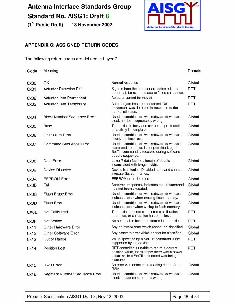
Antenna Interface Standards GroupStandard No. AISG1: Draft 8
(1st Public Draft) 18 November 2002
Protocol Specification AISG1 Draft 8, Nov 18, 2002 Page 48 of 54
APPENDIX C: ASSIGNED RETURN CODES
The following return codes are defined in Layer 7
Code Meaning Domain
0x00 OK Normal response Global
0x01 Actuator Detection Fail Signals from the actuator are detected but areabnormal, for example due to failed calibration.
RET
0x02 Actuator Jam Permanent Actuator cannot be moved RET
0x03 Actuator Jam Temporary Actuator jam has been detected. Nomovement was detected in response to thenormal stimulus.
RET
0x04 Block Number Sequence Error Used in combination with software download;block number sequence is wrong.
Global
0x05 Busy The device is busy and cannot respond untilan activity is complete.
Global
0x06 Checksum Error Used in combination with software download;checksum incorrect.
Global
0x07 Command Sequence Error Used in combination with software download;command sequence is not permitted, eg aSetTilt command is received during softwareupdate sequence.
Global
0x08 Data Error Layer 7 data fault, eg length of data isinconsistent with length fields.
Global
0x09 Device Disabled Device is in logical Disabled state and cannotexecute Set commands.
Global
0x0A EEPROM Error EEPROM error detected Global
0x0B Fail Abnormal response. Indicates that a commandhas not been executed.
Global
0x0C Flash Erase Error Used in combination with software download.indicates error when erasing flash memory.
Global
0x0D Flash Error Used in combination with software download.indicates error when writing to flash memory.
Global
0X0E Not Calibrated The device has not completed a calibrationoperation, or calibration has been lost.
RET
0x0F Not Scaled No setup table has been stored in the device. RET
0x11 Other Hardware Error Any hardware error which cannot be classified. Global
0x12 Other Software Error Any software error which cannot be classified. Global
0x13 Out of Range Value specified by a Set Tilt command is notsupported by the device.
RET
0x14 Position Lost RET controller is unable to return a correctposition value, for example there was a powerfailure while a SetTilt command was beingexecuted.
RET
0x15 RAM Error An error was detected in reading data to/fromRAM
Global
0x16 Segment Number Sequence Error Used in combination with software download;block sequence number is wrong.
Global

Antenna Interface Standards GroupStandard No. AISG1: Draft 8
(1st Public Draft) 18 November 2002
Protocol Specification AISG1 Draft 8, Nov 18, 2002 Page 49 of 54
0x17 UART Error Hardware specific. This error may be sentafter recovery from a temporary error whichhas prevented the sending or receiving ofdata.
Global
0x19 Unknown Command Received command is not defined in theversion of AISG1 transmitted in the frameheader, or the device has received a vendor-specific command with a vendor ID differentfrom its own.
Global
0x1A TMA Alarm Minor An event has taken place that effects the TMAperformance, the TMA continues to functionand bypass is not implemented. (The actualperformance degradation criteria must bevendor specified.)
TMA
0x1B TMA Alarm Major An event has taken place that renders TMAperformance unacceptable. If bypass is fittedthe TMA will switch into bypass.
TMA
0x1C Gain out of Range A SetGain command was received whichspecified a gain out side the range supported.
TMA

Antenna Interface Standards GroupStandard No. AISG1: Draft 8
(1st Public Draft) 18 November 2002
Protocol Specification AISG1 Draft 8, Nov 18, 2002 Page 50 of 54
APPENDIX D ASSIGNED FIELDS FOR ADDITIONAL DATA
The following standard fields are used by the commands SetDeviceData andGetDeviceData. Little-endian order is used for storage of multiple-byte numbers. WhereASCII variables are shorter than the assigned field lengths the characters are rightaligned and leading blanks are filled with zeros (0x00): 00000STRINGHERE = 15 bytes.
Field No. Length(bytes)
Format Description
Antenna data
0x01 15 ASCII Antenna model number
0x02 17 ASCII Antenna serial number
0x03 2 16-bitunsigned
Antenna frequency band(s): see below
0x04 3 3 x 8-bitunsigned
Beamwidth for each band in frequency order (deg)
(example 800/900MHz, 1800/1900MHz, 2100MHz)
0x05 3 3 x 8-bitunsigned
Gain for each band in frequency order (dB/10)
(example 800/900MHz, 1800/1900MHz, 2100MHz)
0x06 2 16-bit signed Maximum supported tilt (degrees/10), Format as Para 8.5.3.
0x07 2 16-bit signed Minimum supported tilt (degrees/10), Format as Para 8.5.3.
TMA data
0x11 15 ASCII TMA model number
0x12 17 ASCII TMA Serial number
0x13 1 8-bitunsigned
TMA type: see below
0x14 4 32-bitunsigned
TMA receive frequency band (see below)
0x15 4 32-bitunsigned
TMA transmit frequency band (see below)
0x16 1 8-bitunsigned
Maximum supported gain (dB/4)
0x17 1 8-bitunsigned
Minimum supported gain (dB/4)
0x18 1 8-bitunsigned
Gain resolution (=dB/16)
Operator data
0x21 6 ASCII Installation date
0x22 5 ASCII Installer’s ID
0x23 12 ASCII Base station ID
0x24 4 ASCII Sector ID
0x25 2 16-bitunsigned
Antenna bearing
0x26 1 8-bit signed Installed mechanical tilt (degrees/10)

Antenna Interface Standards GroupStandard No. AISG1: Draft 8
(1st Public Draft) 18 November 2002
Protocol Specification AISG1 Draft 8, Nov 18, 2002 Page 51 of 54
Fields 0x03 and 0x13
Field 0x03 Field 0x13Bit No Frequency
band(MHz)TMA Type
1 800 Bypass2 900 VSWR3 1500 Reserved4 1700 Reserved5 1900 Reserved6 2100 Reserved7 andabove
Reserved Reserved
Examples of frequency bands: 00010000 = 1700MHz,00011100 = 1700, 1900 and 2100MHz
Fields 0x14 and 0x15:
<fmin low byte> <fmin high byte> <fmax low byte> <fmax high byte>
Where fmin and fmax are calculated in 100kHz steps from 0.

Antenna Interface Standards GroupStandard No. AISG1: Draft 8
(1st Public Draft) 18 November 2002
Protocol Specification AISG1 Draft 8, Nov 18, 2002 Page 52 of 54
APPENDIX E: COMMAND SEQUENCE FOR DOWNLOAD OF SOFTWARE TO ASECONDARY STATION
* Note: Deletion of a previous storedprogram may be carried out at anyappropriate stage of the programdownload process.
HDLC-ALAP
Store Data Block Seg
Store Data Start
Download Start
Primary StationSecondary Station
(RET, TMA &c)
Delete flash*
Repeatedfor everydata-block
Store Data Block Seg response
Store data block segment to bufferRepeated forevery blocksegment untilthe completedata block istransmitted andacknowledged
If buffer is full (typical 128 Bytes):Store data block to flash
Download End
Calculate andcompare checksum
Response
Response

Antenna Interface Standards GroupStandard No. AISG1: Draft 8
(1st Public Draft) 18 November 2002
Protocol Specification AISG1 Draft 8, Nov 18, 2002 Page 53 of 54
APPENDIX F: FREQUENCIES RESERVED FOR PROPRIETARY USE FORSIGNALLING IN COAXIAL CABLES
The following frequencies are known to be in use in proprietary systems andshall be avoided when selecting operating frequencies for data carriers in coaxialcable systems. See paragraph 6.6.1 of this specification.
(No frequencies currently notified)
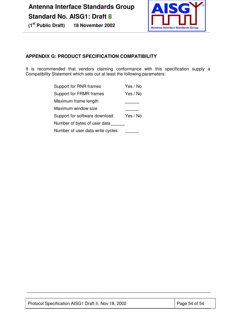
Antenna Interface Standards GroupStandard No. AISG1: Draft 8
(1st Public Draft) 18 November 2002
Protocol Specification AISG1 Draft 8, Nov 18, 2002 Page 54 of 54
APPENDIX G: PRODUCT SPECIFICATION COMPATIBILITY
It is recommended that vendors claiming conformance with this specification supply aCompatibility Statement which sets out at least the following parameters:
Support for RNR frames Yes / No
Support for FRMR frames Yes / No
Maximum frame length
Maximum window size
Support for software download Yes / No
Number of bytes of user data
Number of user data write cycles