38103 - Muhammad Wisnu C - Electromagnetics C
7
Elektromagnetika Kelas C Muhammad Wisnu Cakrawiguna 11/318537/TK/38103 Ali!ation o" Magneti! #arti!le $nse!tion in the %ield o" the &o!omoti'e $ndustr( A)stra!t* The magnetic particle method is established since 80 years as a method for the prove of surface cracks in ferromagnetic material. The MT method (MT = magnetic testing) is one of the most simple and most sensitive methods in NT. !sing MT surface defects can be detected safely even along comple" geometries. The most important cause of a damage# the crack# the surface of a component is t$o times $eaker than the inside. This leads us to the fact that the highest forces affect the $eakest regions of a part. ue to this# surface crack detection once more sho$s its significance in mass production. %ince the MT results are al$a ys pict orial the magn etic partic le test ing method is a inte gral NT method that perfectly matches the sensor y needs of the human inspector . ue to this and due to the fact that the proce ss of magneti&ation and spraying can be applied upon the $hole surface of the component in one go# the MT method sho$s a very high potential to be fully automated and production line integrated. The follo$ing passages $ill sho$ e"amples from the locomotive industry that $ill give an idea ho$ magnetic testing combined $ith machine vision and a self controlling structure turns into a fully automated and production integrated NT method. Ke(words' Nondestructive Testing# Magnetic article *nspection# +ocomotive *ndustry# Machine ,ision $ntrodu!tion Mat erial def ect s are un$ant ed contaminants right from ra$ mat erial to fur nis hed pro duct s due to ina de-uat e process adopted during metallurgical cha nge ma nufact ur ing et c. Mate ri al def ects can be app eared in di ff er ent forms. s an e"ample the some defects have to be mentioned here non metallic in cl us io ns de fects# manuf acturers def ect s# high surface deca rburi&ation def ects # bad mi cr ostr ucture defects# surface cor ros ion def ect s# mec hanical damage defects# surface defect# *nternal defects etc. The repre sented e"amples don/t have to lead to the failure of the material in every case. These are merely e"amined on the mat erial surface and material insides as $ell as of structure anomal ie s# $hi ch di ffers fr om the standard. efects play a crucial role in in flu en ci ng th e va rious mat er ial s properties# and e"hibit comple" structure on varying length scales from electronic struct ure of the defect core (sub nanometer and belo$) to elastic fields of the continuum (micrometer and beyond). e fe cts in mat er ial s may be det ect ed by various proces ses such as Magnet ic par ti cl e inspecti on# ray ra di ogra phy# 1amma ra di ogra phy# !ltrasonic testing# 2lectrical method# amping test# Nonmagnetic method of non de struct ive te st ing# 3pti cal hologr aphy metho d and 4a rdness test. This study is limited to surface5su bsurf ace imper fecti on $hich is det ected through magnet ic parti cle crack detection techni-ue each process is re -uired vi sual inspec ti on. %o it is $orking to discuss about visual imperfection. ,isual test ing is pr obably the most impor tant of all magnetic particle crack detection tests. *t can often provide valuable information about defects. The visua l inspe ction ho$ever should not be conf ined onl y to the st ruct ur e being in vestigated. *t should also in cl ude
Transcript of 38103 - Muhammad Wisnu C - Electromagnetics C
8/11/2019 38103 - Muhammad Wisnu C - Electromagnetics C
http://slidepdf.com/reader/full/38103-muhammad-wisnu-c-electromagnetics-c 1/7
Elektromagnetika
Kelas C
Muhammad Wisnu Cakrawiguna
11/318537/TK/38103
Ali!ation o" Magneti! #arti!le $nse!tion in the %ield o" the &o!omoti'e
$ndustr(
A)stra!t* The magnetic particle method is established since 80 years as a method for the prove of
surface cracks in ferromagnetic material. The MT method (MT = magnetic testing) is one of the most
simple and most sensitive methods in NT. !sing MT surface defects can be detected safely even alongcomple" geometries. The most important cause of a damage# the crack# the surface of a component is t$o
times $eaker than the inside. This leads us to the fact that the highest forces affect the $eakest regions of a
part. ue to this# surface crack detection once more sho$s its significance in mass production. %ince theMT results are al$ays pictorial the magnetic particle testing method is a integral NT method that
perfectly matches the sensory needs of the human inspector. ue to this and due to the fact that the process
of magneti&ation and spraying can be applied upon the $hole surface of the component in one go# the MT
method sho$s a very high potential to be fully automated and production line integrated. The follo$ing passages $ill sho$ e"amples from the locomotive industry that $ill give an idea ho$ magnetic testing
combined $ith machine vision and a self controlling structure turns into a fully automated and production
integrated NT method.
Ke(words' Nondestructive Testing# Magnetic article *nspection# +ocomotive *ndustry#
Machine ,ision
$ntrodu!tion
Material defects are un$anted
contaminants right from ra$ material tofurnished products due to inade-uate
process adopted during metallurgical
change manufacturing etc. Material
defects can be appeared in differentforms. s an e"ample the some defects
have to be mentioned here non metallicinclusions defects# manufacturers
defects# high surface decarburi&ation
defects# bad microstructure defects#
surface corrosion defects# mechanicaldamage defects# surface defect# *nternal
defects etc.
The represented e"amples don/thave to lead to the failure of the material
in every case. These are merelye"amined on the material surface andmaterial insides as $ell as of structure
anomalies# $hich differs from the
standard. efects play a crucial role in
influencing the various materials properties# and e"hibit comple" structure
on varying length scales from electronic
structure of the defect core (sub
nanometer and belo$) to elastic fields of
the continuum (micrometer and beyond).efects in materials may be
detected by various processes such as
Magnetic particle inspection# ray
radiography# 1amma radiography#!ltrasonic testing# 2lectrical method#
amping test# Nonmagnetic method of nondestructive testing# 3ptical
holography method and 4ardness test.
This study is limited to
surface5subsurface imperfection $hichis detected through magnetic particle
crack detection techni-ue each process is
re-uired visual inspection. %o it is$orking to discuss about visual
imperfection.,isual testing is probably themost important of all magnetic particle
crack detection tests. *t can often provide
valuable information about defects. The
visual inspection ho$ever should not beconfined only to the structure being
investigated. *t should also include
8/11/2019 38103 - Muhammad Wisnu C - Electromagnetics C
http://slidepdf.com/reader/full/38103-muhammad-wisnu-c-electromagnetics-c 2/7
neighboring structures# the surrounding
environment and the climatic and
services condition. This test report helpsthe component authority to allo$ their
safe use in the installation. ue to time
constraints it $as decided to take uponly magnetic particle crack detection
testing of locomotive components. %o
this is an attempt to learn about themagnetic particle crack detection testing
of materials in general# but locomotive
gear components in particular.
1+ Magneti! testing o" dri'e sha"ts
3ne application from the field of
the sub suppliers of automotive parts is
the fully locomotive inspection of driveshafts. 2"ample# rive shafts are
cylindrical parts of a length of 600 mmto 70 mm and a diameter of 9: mm to
6; mm.
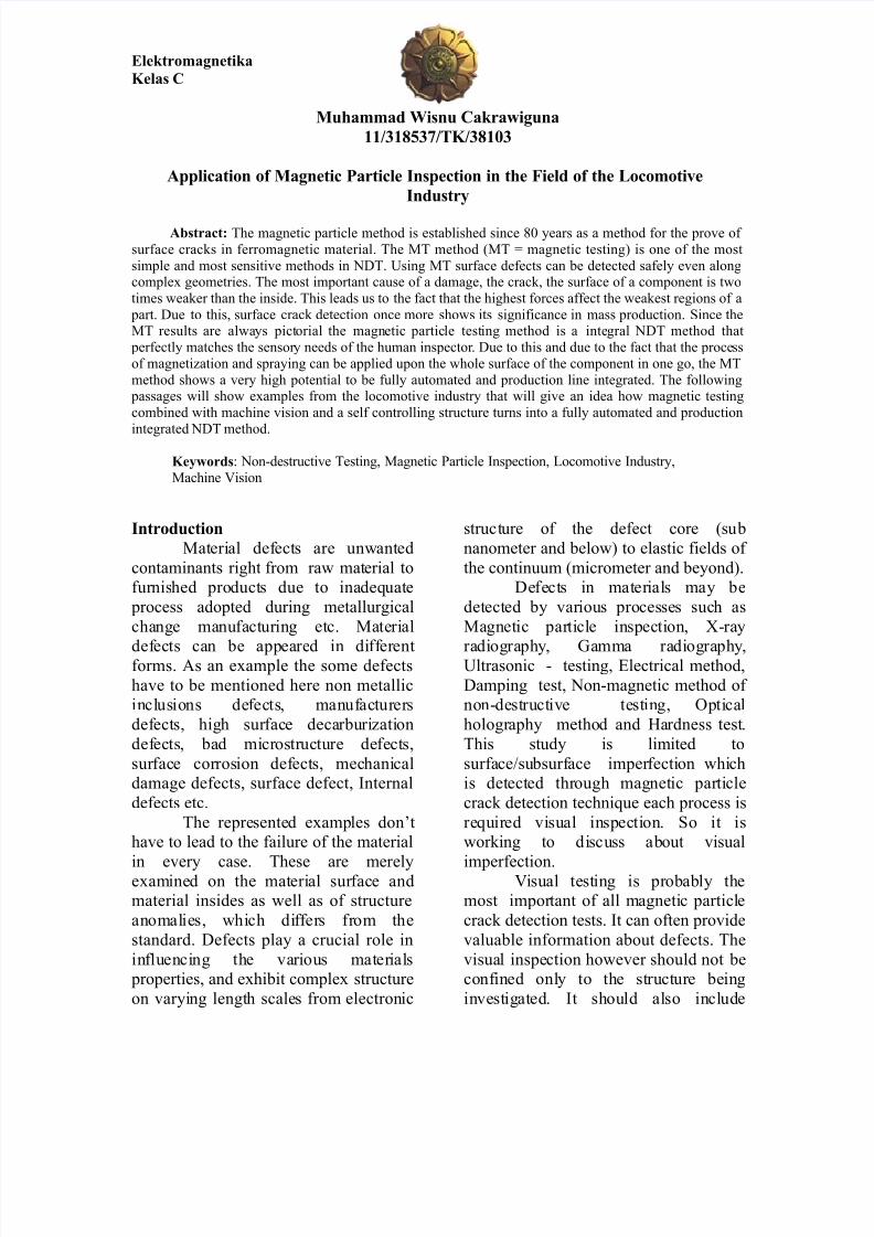
<ig. 9' rive shaft# length' 90 mm<igure 9 sho$s such a shaft that
is toothed and hardened at both ends.
Typical fla$s on this components arematerial a hardening defects. <igure;
sho$s a materials defect after
magneti&ation and spraying $ith M*
test ink under !, light. The system basically is designed as a $alking beam
that leads the parts into the single
stations of the inspection process. <igure6 sho$s the part entrance of the machine
that is designed as a slope on $hich the
parts are piled up in a ro$.
<ig.;' Material defect under !, light
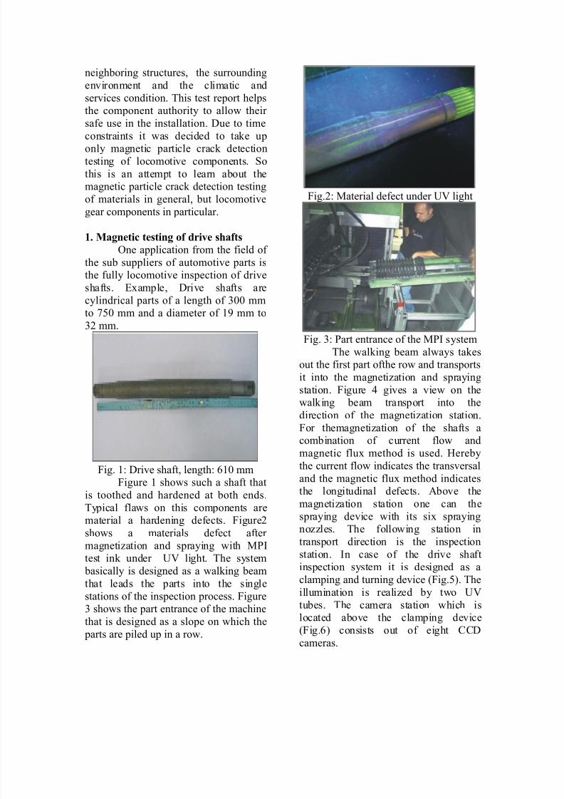
<ig. 6' art entrance of the M* system
The $alking beam al$ays takesout the first part ofthe ro$ and transports
it into the magneti&ation and spraying
station. <igure > gives a vie$ on the$alking beam transport into the
direction of the magneti&ation station.<or themagneti&ation of the shafts acombination of current flo$ and
magnetic flu" method is used. 4ereby
the current flo$ indicates the transversal
and the magnetic flu" method indicatesthe longitudinal defects. bove the
magneti&ation station one can the
spraying device $ith its si" sprayingno&&les. The follo$ing station in
transport direction is the inspection
station. *n case of the drive shaftinspection system it is designed as a
clamping and turning device (<ig.). The
illumination is reali&ed by t$o !,
tubes. The camera station $hich islocated above the clamping device
(<ig.) consists out of eight ??
cameras.
8/11/2019 38103 - Muhammad Wisnu C - Electromagnetics C
http://slidepdf.com/reader/full/38103-muhammad-wisnu-c-electromagnetics-c 3/7
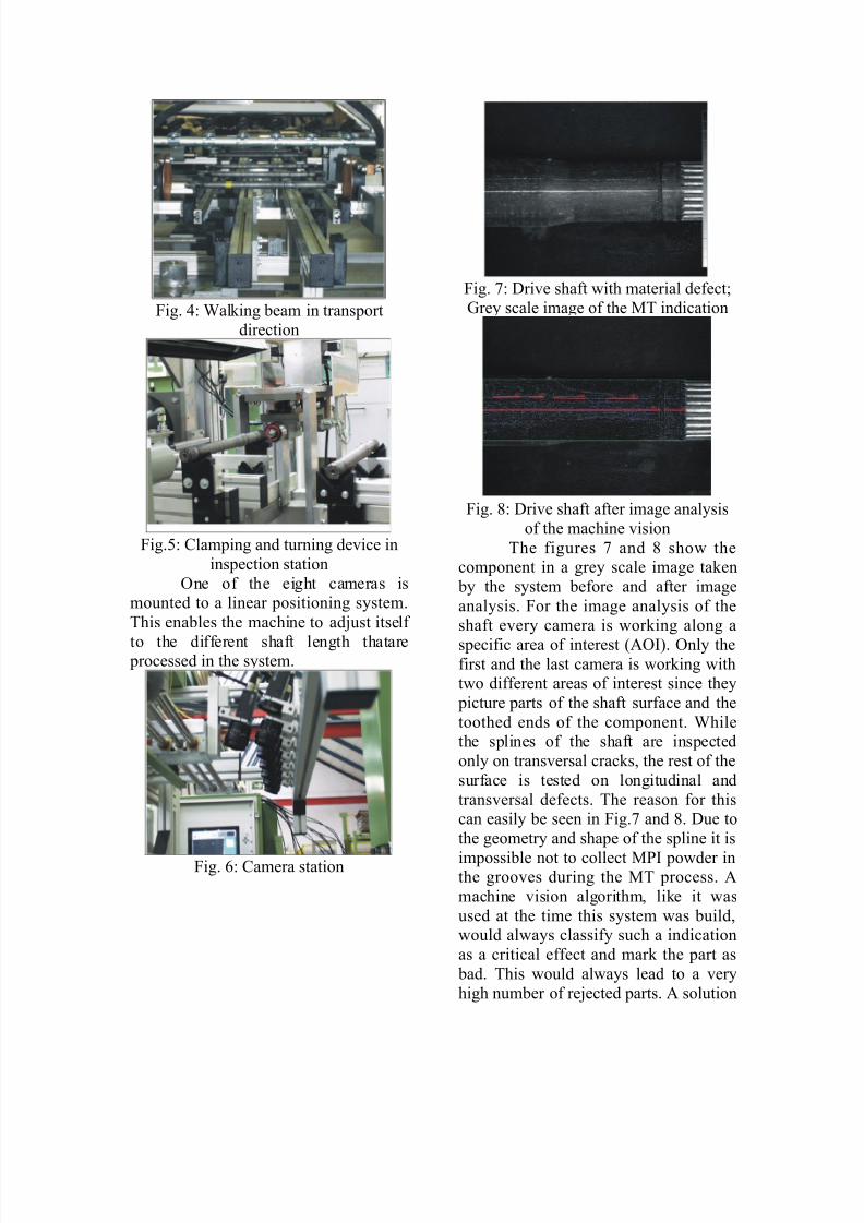
<ig. >' @alking beam in transport
direction
<ig.' ?lamping and turning device in
inspection station
3ne of the eight cameras ismounted to a linear positioning system.
This enables the machine to adAust itself
to the different shaft length thatare processed in the system.
<ig. ' ?amera station
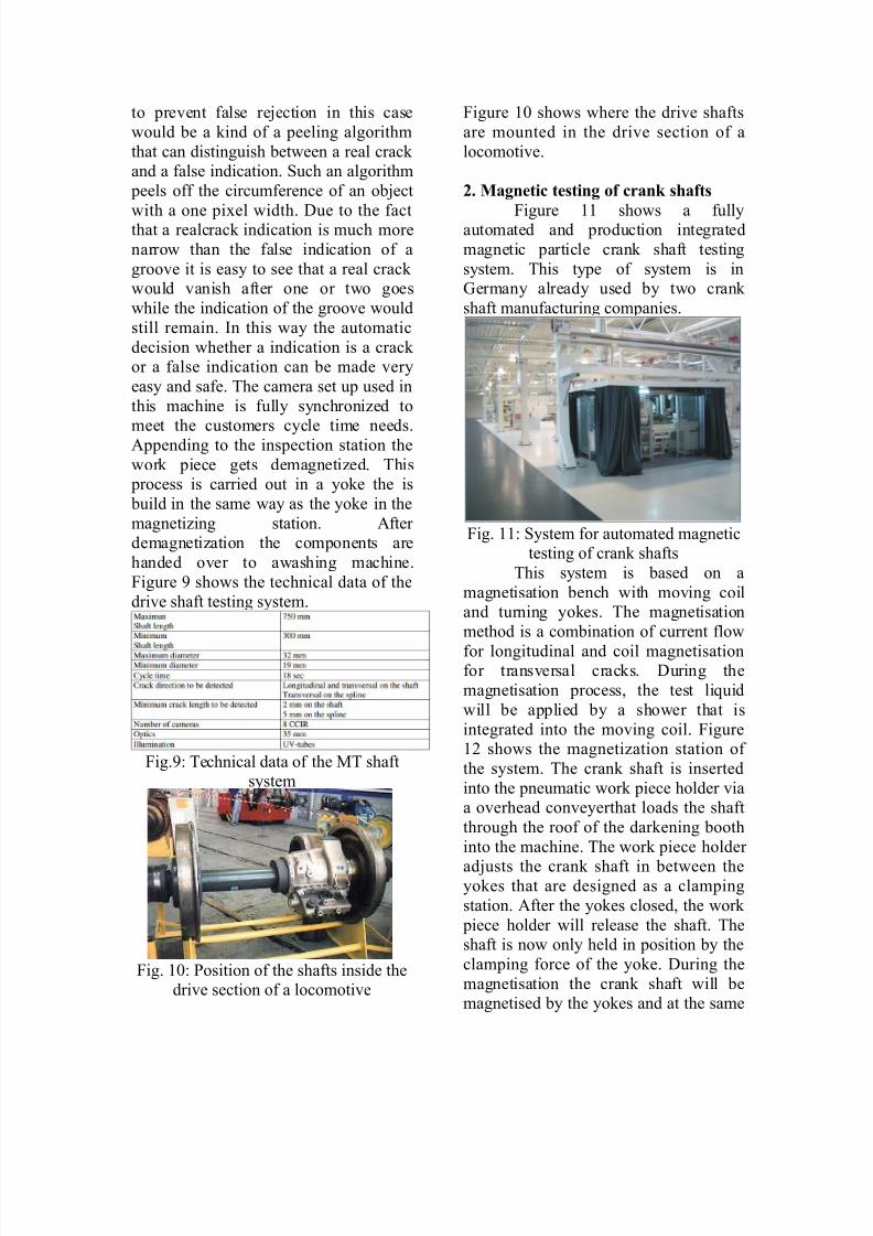
<ig. 7' rive shaft $ith material defectB1rey scale image of the MT indication
<ig. 8' rive shaft after image analysis
of the machine vision
The figures 7 and 8 sho$ thecomponent in a grey scale image taken
by the system before and after image
analysis. <or the image analysis of theshaft every camera is $orking along a
specific area of interest (3*). 3nly thefirst and the last camera is $orking $itht$o different areas of interest since they
picture parts of the shaft surface and the
toothed ends of the component. @hilethe splines of the shaft are inspected
only on transversal cracks# the rest of the
surface is tested on longitudinal and
transversal defects. The reason for thiscan easily be seen in <ig.7 and 8. ue to
the geometry and shape of the spline it is
impossible not to collect M* po$der inthe grooves during the MT process.
machine vision algorithm# like it $as
used at the time this system $as build#$ould al$ays classify such a indication
as a critical effect and mark the part as
bad. This $ould al$ays lead to a very
high number of reAected parts. solution
8/11/2019 38103 - Muhammad Wisnu C - Electromagnetics C
http://slidepdf.com/reader/full/38103-muhammad-wisnu-c-electromagnetics-c 4/7
to prevent false reAection in this case
$ould be a kind of a peeling algorithm
that can distinguish bet$een a real crack and a false indication. %uch an algorithm
peels off the circumference of an obAect
$ith a one pi"el $idth. ue to the factthat a realcrack indication is much more
narro$ than the false indication of a
groove it is easy to see that a real crack $ould vanish after one or t$o goes
$hile the indication of the groove $ould
still remain. *n this $ay the automatic
decision $hether a indication is a crack or a false indication can be made very
easy and safe. The camera set up used in
this machine is fully synchroni&ed to
meet the customers cycle time needs.ppending to the inspection station the
$ork piece gets demagneti&ed. This process is carried out in a yoke the is
build in the same $ay as the yoke in the
magneti&ing station. fter demagneti&ation the components are
handed over to a$ashing machine.
<igure : sho$s the technical data of the
drive shaft testing system.
<ig.:' Technical data of the MT shaftsystem
<ig. 90' osition of the shafts inside thedrive section of a locomotive
<igure 90 sho$s $here the drive shafts
are mounted in the drive section of a
locomotive.
,+ Magneti! testing o" !rank sha"ts
<igure 99 sho$s a fullyautomated and production integrated
magnetic particle crank shaft testing
system. This type of system is in1ermany already used by t$o crank
shaft manufacturing companies.
<ig. 99' %ystem for automated magnetictesting of crank shafts
This system is based on a
magnetisation bench $ith moving coiland turning yokes. The magnetisation
method is a combination of current flo$
for longitudinal and coil magnetisationfor transversal cracks. uring the
magnetisation process# the test li-uid
$ill be applied by a sho$er that is
integrated into the moving coil. <igure9; sho$s the magneti&ation station of
the system. The crank shaft is inserted
into the pneumatic $ork piece holder viaa overhead conveyerthat loads the shaft
through the roof of the darkening booth
into the machine. The $ork piece holder
adAusts the crank shaft in bet$een theyokes that are designed as a clamping
station. fter the yokes closed# the $ork
piece holder $ill release the shaft. Theshaft is no$ only held in position by the
clamping force of the yoke. uring the
magnetisation the crank shaft $ill bemagnetised by the yokes and at the same
8/11/2019 38103 - Muhammad Wisnu C - Electromagnetics C
http://slidepdf.com/reader/full/38103-muhammad-wisnu-c-electromagnetics-c 5/7
time by themoving coil $hich can be
seen on the left side of fig.9;. fter the
magnetisation process is carried out# thecoil moves back into its initial position
and the crack detection se-uence begins.
The crank shaft has to be turned toenable the machine vision system to
inspect it. ueto the fact that such a
shaft has got no symmetrical shape# thefully automated inspection by cameras is
not trivial. <or the magnetic particle
testing of finished crank shafts the
inspection of all machined surfaces arenecessary. <or a four cylinder crank
shaft# like sho$n in fig.9;# this means
that four Aournals and five main bearings
have to be inspected. lus severalfittings for counter$eights.
<ig. 9;' Magnetisation station $ith yokeand coil
3n crank shafts that are designed for a
higher number of pistons very often t$orelated Aournals are not separated but
combined to each other like sho$n in
figure 96.
<ig. 96' 90cylinder crank shaft (upper
image)# combined Aournals (arro$)BMaterial defect on crank shaftB MT
indication
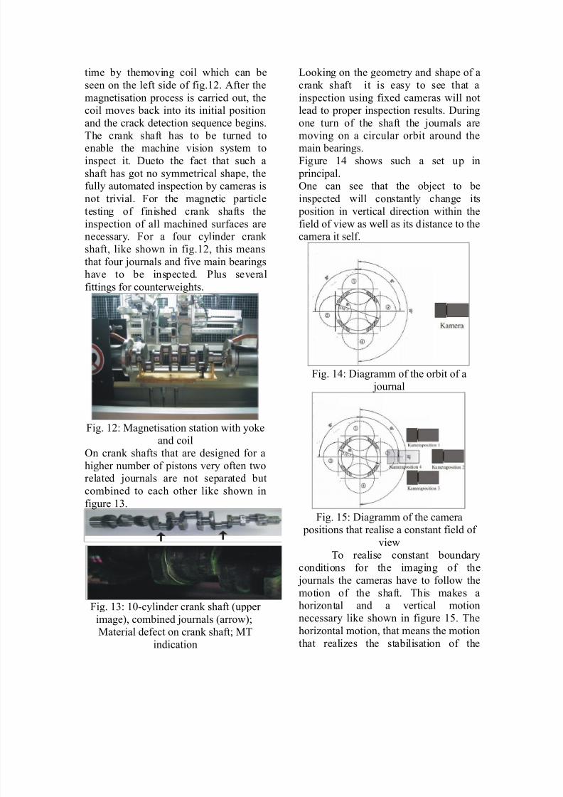
+ooking on the geometry and shape of a
crank shaft it is easy to see that a
inspection using fi"ed cameras $ill notlead to proper inspection results. uring
one turn of the shaft the Aournals are
moving on a circular orbit around themain bearings.
<igure 9> sho$s such a set up in
principal.3ne can see that the obAect to be
inspected $ill constantly change its
position in vertical direction $ithin the
field of vie$ as $ell as its distance to thecamera it self.
<ig. 9>' iagramm of the orbit of a
Aournal
<ig. 9' iagramm of the camera positions that realise a constant field of
vie$
To realise constant boundaryconditions for the imaging of the
Aournals the cameras have to follo$ the
motion of the shaft. This makes ahori&ontal and a vertical motion
necessary like sho$n in figure 9. The
hori&ontal motion# that means the motion
that reali&es the stabilisation of the
8/11/2019 38103 - Muhammad Wisnu C - Electromagnetics C
http://slidepdf.com/reader/full/38103-muhammad-wisnu-c-electromagnetics-c 6/7
distance bet$een camera and Aournal#
could theoretically be replaced by using
motori&ed &oom optics. Cut due to thefact that these kind of optics change their
transmittance in dependence of the focal
length this solution is not practicalcompared to the use of a linear a"is.The
variation in transmittanceleads to the
problem that t$o obAects# comparable insi&e and brightness# in different distances
to the camera $ill be displayed in
al$ays the same si&e but in different
brightness.This means that a $orkingmeasuring system based on a &oom optic
al$ays has to match its sensor sensitivity
in dependence to the focal length.
<ig. 9' ?amera station of the crank
shaft inspection system $ith 6d
positioning unit<igure 9 sho$s camera station
of the crank shaft MT system. *t ise-uipped $ith t$o cameras $ith 6 mm
optics. 2very imaging unit is mounted to
6d positioning system that consists of 6linear a"is each. *n this $ay al$ays t$o
Aournals can be inspected at once. The
illumination system is e-uipped $ith
t$o !,+2 sources on each side (<ig.9 yello$ arro$). The first automated
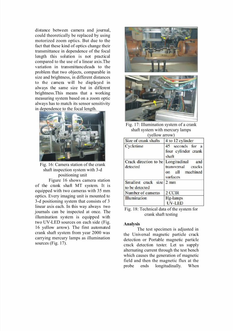
crank shaft system from year ;000 $ascarrying mercury lamps as illuminationsources (<ig. 97).
<ig. 97' *llumination system of a crank
shaft system $ith mercury lamps(yello$ arro$)
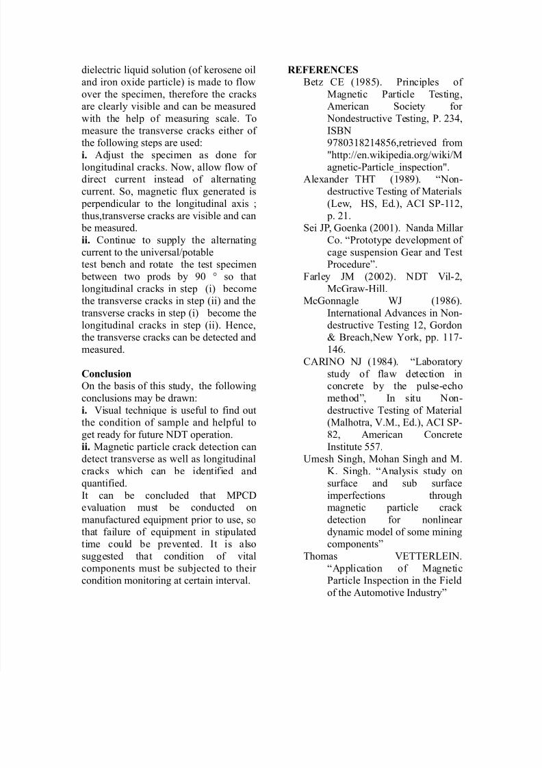
<ig. 98' Technical data of the system for
crank shaft testing
Anal(sis
The test specimen is adAusted in
the !niversal magnetic particle crack
detection or ortable magnetic particlecrack detection tester. +et us supply
alternating current through the test bench
$hich causes the generation of magneticfield and then the magnetic flu" at the
probe ends longitudinally. @hen
8/11/2019 38103 - Muhammad Wisnu C - Electromagnetics C
http://slidepdf.com/reader/full/38103-muhammad-wisnu-c-electromagnetics-c 7/7
dielectric li-uid solution (of kerosene oil
and iron o"ide particle) is made to flo$
over the specimen# therefore the cracksare clearly visible and can be measured
$ith the help of measuring scale. To
measure the transverse cracks either of the follo$ing steps are used'
i+ dAust the specimen as done for
longitudinal cracks. No$# allo$ flo$ of direct current instead of alternating
current. %o# magnetic flu" generated is
perpendicular to the longitudinal a"is B
thus#transverse cracks are visible and can be measured.
ii+ ?ontinue to supply the alternating
current to the universal5potable
test bench and rotate the test specimen bet$een t$o prods by :0 D so that
longitudinal cracks in step (i) becomethe transverse cracks in step (ii) and the
transverse cracks in step (i) become the
longitudinal cracks in step (ii). 4ence#the transverse cracks can be detected and
measured.
Con!lusion
3n the basis of this study# the follo$ing
conclusions may be dra$n'
i+ ,isual techni-ue is useful to find outthe condition of sample and helpful to
get ready for future NT operation.
ii+ Magnetic particle crack detection candetect transverse as $ell as longitudinal
cracks $hich can be identified and
-uantified.
*t can be concluded that M?evaluation must be conducted on
manufactured e-uipment prior to use# so
that failure of e-uipment in stipulatedtime could be prevented. *t is also
suggested that condition of vital
components must be subAected to their condition monitoring at certain interval.
-E%E-E.CE
Cet& ?2 (9:8). rinciples of
Magnetic article Testing#merican %ociety for
Nondestructive Testing# . ;6>#
*%CN:780698;9>8#retrieved from
Ehttp'55en.$ikipedia.org5$iki5M
agneticarticleFinspectionE.le"ander T4T (9:8:). GNon
destructive Testing of Materials
(+e$# 4%# 2d.)# ?* %99;#
p. ;9.%ei H# 1oenka (;009). Nanda Millar
?o. Grototype development of
cage suspension 1ear and Test
rocedureI.<arley HM (;00;). NT ,il;#
Mc1ra$4ill.Mc1onnagle @H (9:8).
*nternational dvances in Non
destructive Testing 9;# 1ordonJ Creach#Ne$ Kork# pp. 997
9>.
?L*N3 NH (9:8>). G+aboratory
study of fla$ detection inconcrete by the pulseecho
methodI# *n situ Non
destructive Testing of Material(Malhotra# ,.M.# 2d.)# ?* %
8;# merican ?oncrete
*nstitute 7.!mesh %ingh# Mohan %ingh and M.
. %ingh. Gnalysis study on
surface and sub surface
imperfections throughmagnetic particle crack
detection for nonlinear
dynamic model of some miningcomponentsI
Thomas ,2TT2L+2*N.
Gpplication of Magneticarticle *nspection in the <ield
of the utomotive *ndustryI