Adapted from: faculty.sgc.edu/asafer/BIOL1107/chapt06_lecture.ppt.
date post
22-Dec-2015Category
view
220download
0
331 W06.1 Fall 2003
14:332:331Computer Architecture and Assembly Language
Fall 2003
Week 6
[Adapted from Dave Patterson’s UCB CS152 slides and
Mary Jane Irwin’s PSU CSE331 slides]
331 W06.2 Fall 2003
Head’s Up This week’s material
VHDL modeling- Reading assignment – Y, Chapter 4 and 5
MIPS arithmetic operations- Reading assignment – PH 4.1 through 4.3
Next week’s material MIPS logic and multiply instructions
- Reading assignment – PH 4.4
MIPS ALU design- Reading assignment – PH 4.5

331 W06.3 Fall 2003
Review: Entity-Architecture Features
Entity defines externally visible characteristics Ports: channels of communication
Architecture defines the internal behavior or structure
Declaration of internal signals Description of behavior
- concurrent behavioral description: collection of CSA’s
- process behavioral description: CSAs and variable assignment statements within a process description
- structural description: system described in terms of the interconnections of its components
Design Entity-Architecture == Hardware Component
Entity == External Characteristics
Architecture (Body ) == Internal Behavior or Structure
331 W06.4 Fall 2003
Review: Model of Execution CSA’s are executed concurrently - textural order of
the statements is irrelevant to the correct operation
Two stage model of circuit execution first stage
- all CSA’s with events occurring at the current time on signals on their right hand side (RHS) are evaluated
- all future events that are generated from this evaluation are scheduled
second stage- time is advanced to the time of the next event
VHDL programmer specifies events - with CSA’s delays - with CSA’s with delay annotation concurrency - by having a distinct CSA for each signal
331 W06.5 Fall 2003
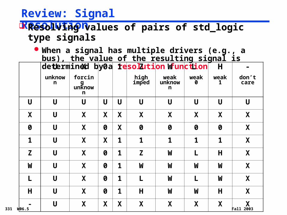
Review: Signal Resolution Resolving values of pairs of std_logic type signals
When a signal has multiple drivers (e.g., a bus), the value of the resulting signal is determined by a resolution function
Uunknow
n
Xforcing unknow
n
0 1 Zhigh
imped
Wweak
unknown
L weak
0
Hweak
1
-don’t care
U U U U U U U U U U
X U X X X X X X X X
0 U X 0 X 0 0 0 0 X
1 U X X 1 1 1 1 1 X
Z U X 0 1 Z W L H X
W U X 0 1 W W W W X
L U X 0 1 L W L W X
H U X 0 1 H W W H X
- U X X X X X X X X
331 W06.6 Fall 2003
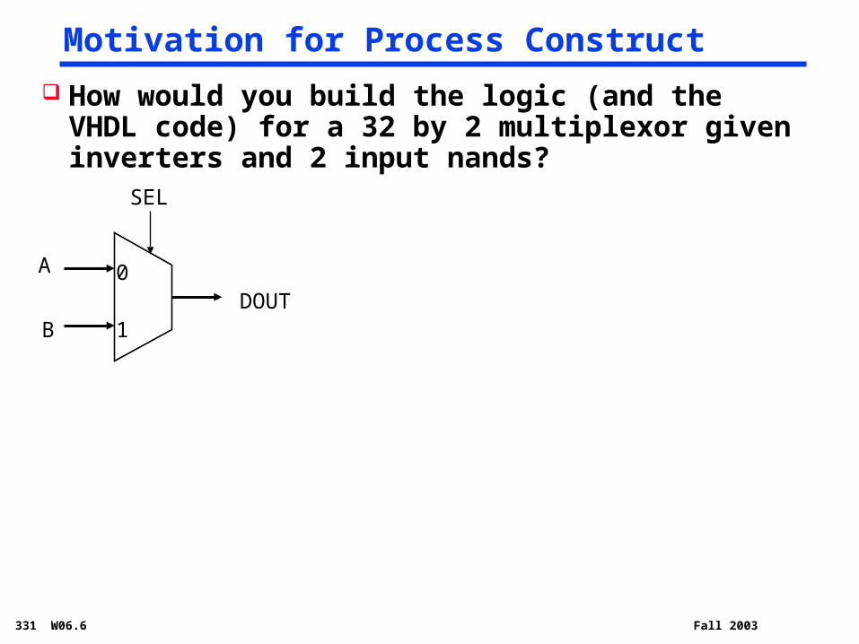
Motivation for Process Construct
How would you build the logic (and the VHDL code) for a 32 by 2 multiplexor given inverters and 2 input nands?
1
0
SEL
A
DOUTB
331 W06.7 Fall 2003
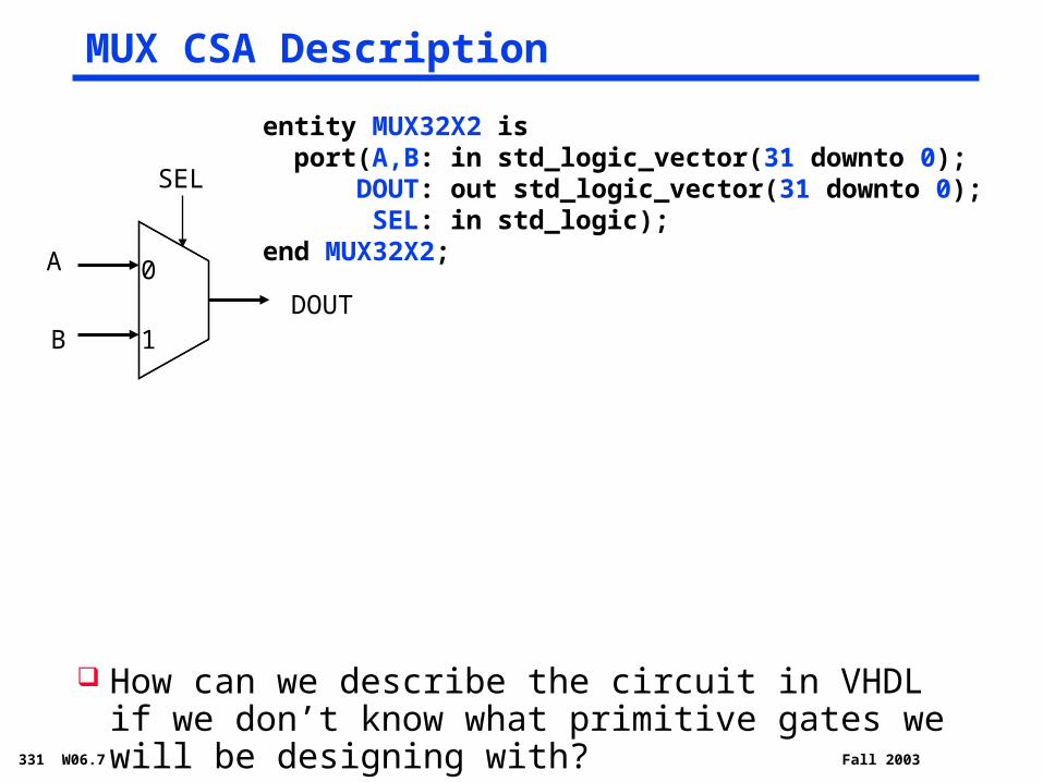
MUX CSA Description
1
0
SEL
A
DOUTB
How can we describe the circuit in VHDL if we don’t know what primitive gates we will be designing with?
entity MUX32X2 is port(A,B: in std_logic_vector(31 downto 0); DOUT: out std_logic_vector(31 downto 0); SEL: in std_logic);end MUX32X2;
331 W06.8 Fall 2003
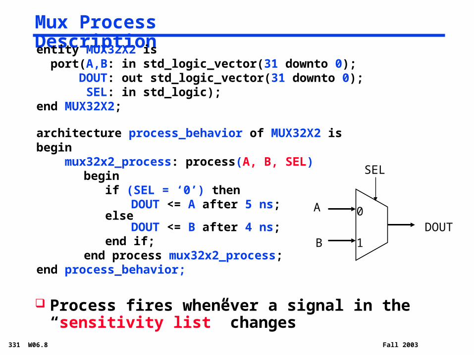
Mux Process Description
Process fires whenever a signal in the “sensitivity list” changes
entity MUX32X2 is port(A,B: in std_logic_vector(31 downto 0); DOUT: out std_logic_vector(31 downto 0); SEL: in std_logic);end MUX32X2;
architecture process_behavior of MUX32X2 isbegin mux32x2_process: process(A, B, SEL)
begin if (SEL = ‘0’) then
DOUT <= A after 5 ns; else
DOUT <= B after 4 ns; end if;end process mux32x2_process;
end process_behavior;
1
0
SEL
A
DOUTB

331 W06.9 Fall 2003
VHDL Process Features
Process body is executed sequentially to completion in zero (simulation) time
Delays are associated only with assignment of values to signals
marked by CSAs <= operator
Variable assignments take effect immediately marked by := operator
Upon initialization all processes are executed once
After initialization processes are data-driven activated by events on signals in sensitivity list waiting for the occurrence of specific events using wait
statements
331 W06.10 Fall 2003
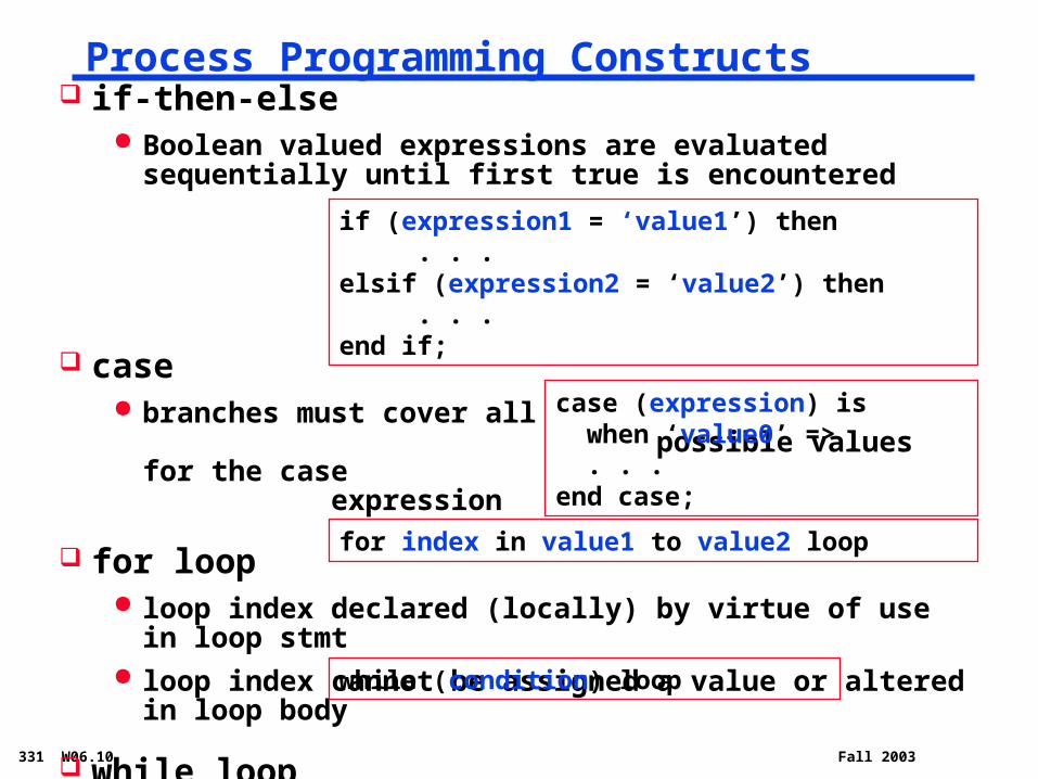
Process Programming Constructs if-then-else
Boolean valued expressions are evaluated sequentially until first true is encountered
case branches must cover all
possible values for the case expression
for loop loop index declared (locally) by virtue of use in loop stmt loop index cannot be assigned a value or altered in loop
body
while loop condition may involve variables modified within the loop
while (condition) loop
for index in value1 to value2 loop
case (expression) is when ‘value0’ => . . .end case;
if (expression1 = ‘value1’) then . . .elsif (expression2 = ‘value2’) then . . .end if;
331 W06.11 Fall 2003
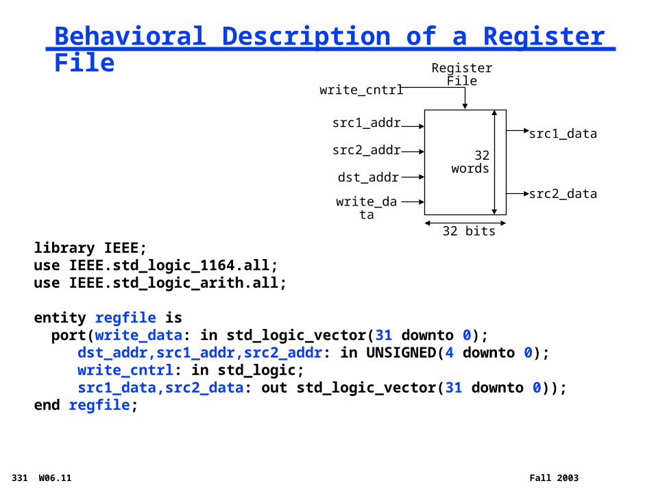
Behavioral Description of a Register File
library IEEE;use IEEE.std_logic_1164.all;use IEEE.std_logic_arith.all;
entity regfile is port(write_data: in std_logic_vector(31 downto 0); dst_addr,src1_addr,src2_addr: in UNSIGNED(4 downto 0); write_cntrl: in std_logic; src1_data,src2_data: out std_logic_vector(31 downto 0));end regfile;
Register File
src1_addr
src2_addr
dst_addr
write_data
32 bits
src1_data
src2_data
32words
write_cntrl

331 W06.12 Fall 2003
Behavioral Description of a Register File, con’t
architecture process_behavior of regfile is type reg_array is array(0 to 31) of std_logic_vector (31 downto 0);begin regfile_process: process(src1_addr,src2_addr,write_cntrl) variable data_array: reg_array := ( (X”00000000”), (X”00000000”), . . . (X”00000000”)); variable addrofsrc1, addrofsrc2, addrofdst: integer; begin addrofsrc1 := conv_integer(src1_addr); addrofsrc2 := conv_integer(src2_addr); addrofdst := conv_integer(dst_addr); if write_cntrl = ‘1’ then data_array(addrofdst) := write_data; end if; src1_data <= data_array(addrofsrc1) after 10 ns; src2_data <= data_array(addrofsrc2) after 10 ns; end process regfile_process;end process_behavior;
331 W06.13 Fall 2003
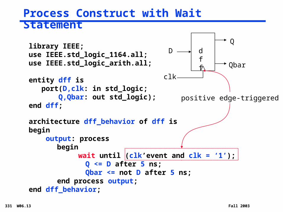
Process Construct with Wait Statement
library IEEE;use IEEE.std_logic_1164.all;use IEEE.std_logic_arith.all;
entity dff is port(D,clk: in std_logic; Q,Qbar: out std_logic);end dff;
architecture dff_behavior of dff isbegin output: process
begin wait until (clk’event and clk = ‘1’);
Q <= D after 5 ns;Qbar <= not D after 5 ns;
end process output;end dff_behavior;
DQ
clk
Qbar
positive edge-triggered
dff

331 W06.14 Fall 2003
Wait Statement Types
Wait statements specify conditions under which a process may resume execution after suspension
wait for time expression
- suspends process for a period of time defined by the time expression
wait on signal
- suspends process until an event occurs on one (or more) of the signals
wait until condition
- suspends process until condition evaluates to specified Boolean
wait
Process resumes execution at the first statement following the wait statement
wait until (clk’event and clk = ‘1’);
wait for (20 ns);
wait on clk, reset, status;

331 W06.15 Fall 2003
Signal Attributes
Function attribute Function
signal_name’event Boolean value signifying a change in value on this signal
signal_name’active Boolean value singifying an assignment made to this signal (may not be a new value!)
signal_name’last_event Time since the last event on this signal
signal_name’last_active Time since the signal was last active
signal_name’last_value Previous value of this signal
Attributes are used to return various types of information about a signal

331 W06.16 Fall 2003
Things to Remember About Processes
A process must have either a sensitivity list or at least one wait statement
A process cannot have both a sensitivity list and a wait statement
Remember, all processes are executed once when the simulation is started
Don’t confuse signals and variables. Signals are declared either in the port definitions in the
entity description or as internal signals in the architecture description. They are used in CSAs. Signals will be updated only after the next simulation cycle.
Variable exist only inside architecture process descriptions. They are used in variable assignment statements. Variables are updated immediately.

331 W06.17 Fall 2003
Finite State Machine “Structure”
D(0)Q(0)
a
clk
b
z
comb
dff
dff D(1)Q(1)
FetchPC = PC+4
DecodeExec
331 W06.18 Fall 2003
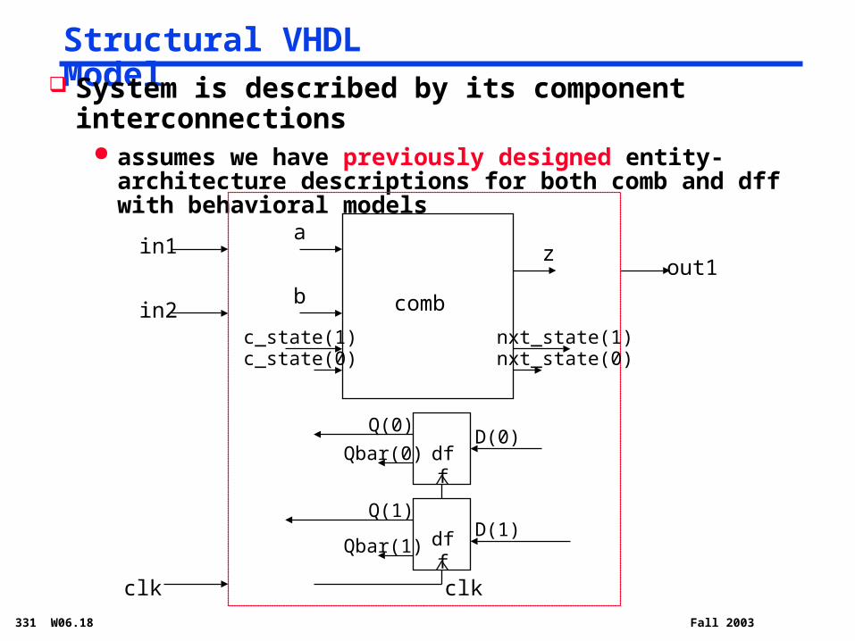
Structural VHDL Model
in1
Qbar(0)
clk
in2
out1
System is described by its component interconnections
assumes we have previously designed entity-architecture descriptions for both comb and dff with behavioral models
comb
c_state(1) nxt_state(1)
b
az
clk
D(0)Q(0)
dff
dff D(1)Q(1)
Qbar(1)
nxt_state(0)c_state(0)
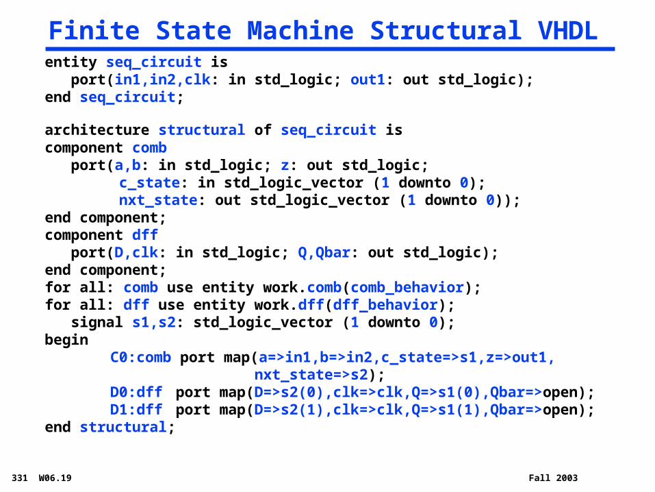
331 W06.19 Fall 2003
Finite State Machine Structural VHDLentity seq_circuit is port(in1,in2,clk: in std_logic; out1: out std_logic);end seq_circuit;
architecture structural of seq_circuit iscomponent comb port(a,b: in std_logic; z: out std_logic;
c_state: in std_logic_vector (1 downto 0); nxt_state: out std_logic_vector (1 downto 0));
end component;component dff port(D,clk: in std_logic; Q,Qbar: out std_logic);end component;for all: comb use entity work.comb(comb_behavior);for all: dff use entity work.dff(dff_behavior); signal s1,s2: std_logic_vector (1 downto 0);begin
C0:comb port map(a=>in1,b=>in2,c_state=>s1,z=>out1, nxt_state=>s2);
D0:dff port map(D=>s2(0),clk=>clk,Q=>s1(0),Qbar=>open);D1:dff port map(D=>s2(1),clk=>clk,Q=>s1(1),Qbar=>open);
end structural;
331 W06.20 Fall 2003
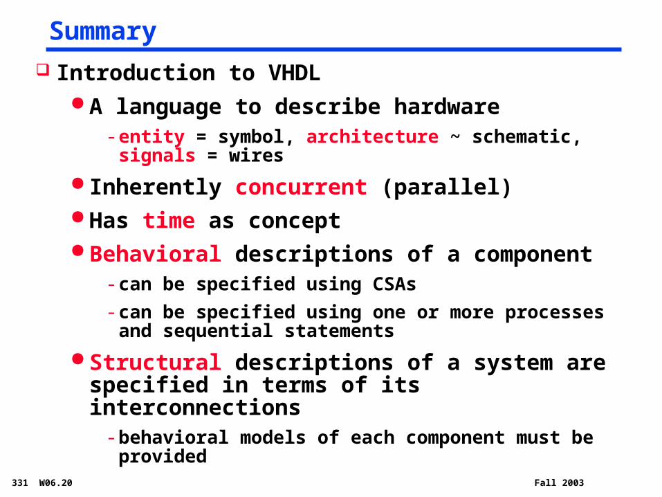
Summary Introduction to VHDL
A language to describe hardware- entity = symbol, architecture ~ schematic, signals =
wires
Inherently concurrent (parallel) Has time as concept Behavioral descriptions of a component
- can be specified using CSAs
- can be specified using one or more processes and sequential statements
Structural descriptions of a system are specified in terms of its interconnections
- behavioral models of each component must be provided

331 W06.21 Fall 2003
Because ease of use is the purpose, this ratio of function to conceptual complexity is the ultimate test of system design. Neither function alone nor simplicity alone defines a good design.
The Mythical Man-Month, Brooks, pg. 43

331 W06.22 Fall 2003
Review: MIPS ISACategory Instr Op Code Example Meaning
Arithmetic
(R & I format)
add 0 and 32 add $s1, $s2, $s3 $s1 = $s2 + $s3
subtract 0 and 34 sub $s1, $s2, $s3 $s1 = $s2 - $s3
add immediate 8 addi $s1, $s2, 6 $s1 = $s2 + 6
or immediate 13 ori $s1, $s2, 6 $s1 = $s2 v 6
Data Transfer
(I format)
load word 35 lw $s1, 24($s2) $s1 = Memory($s2+24)
store word 43 sw $s1, 24($s2) Memory($s2+24) = $s1
load byte 32 lb $s1, 25($s2) $s1 = Memory($s2+25)
store byte 40 sb $s1, 25($s2) Memory($s2+25) = $s1
load upper imm 15 lui $s1, 6 $s1 = 6 * 216
Cond. Branch (I & R format)
br on equal 4 beq $s1, $s2, L if ($s1==$s2) go to L
br on not equal 5 bne $s1, $s2, L if ($s1 !=$s2) go to L
set on less than 0 and 42 slt $s1, $s2, $s3 if ($s2<$s3) $s1=1 else $s1=0
set on less than immediate
10 slti $s1, $s2, 6 if ($s2<6) $s1=1 else $s1=0
Uncond. Jump (J & R format)
jump 2 j 2500 go to 10000
jump register 0 and 8 jr $t1 go to $t1
jump and link 3 jal 2500 go to 10000; $ra=PC+4
331 W06.23 Fall 2003
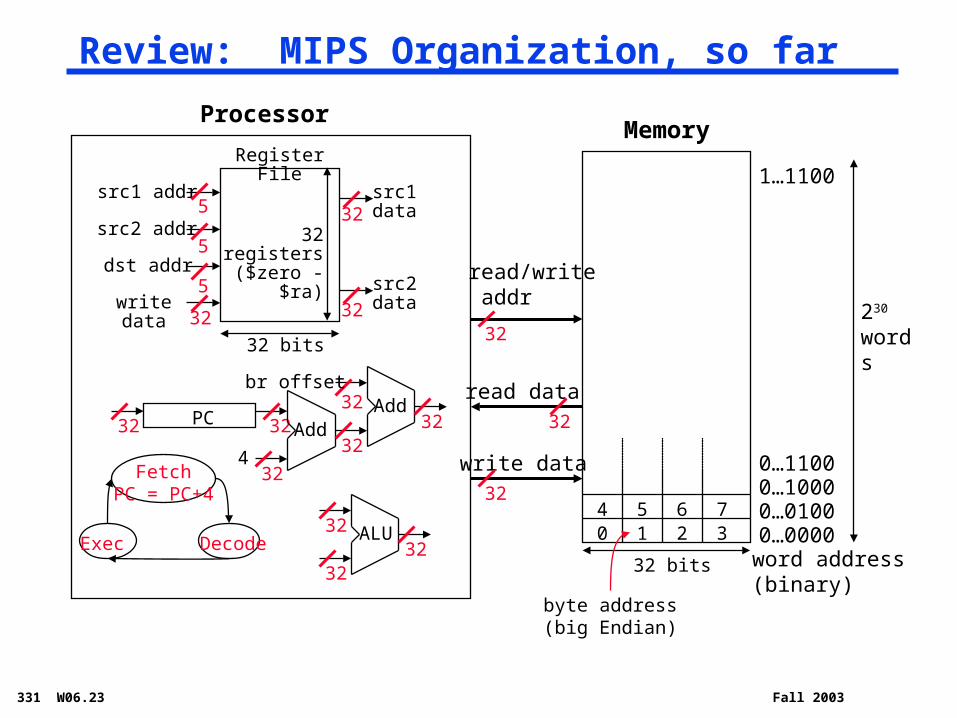
Review: MIPS Organization, so far
ProcessorMemory
32 bits
230
words
read/write addr
read data
write data
word address(binary)
0…00000…01000…10000…1100
1…1100Register File
src1 addr
src2 addr
dst addr
write data
32 bits
src1data
src2data
32registers
($zero - $ra)
32
32
3232
32
32
5
5
5
PC
ALU
32 32
3232
32
0 1 2 37654
byte address(big Endian)
FetchPC = PC+4
DecodeExec
Add32
324
Add32
32br offset
331 W06.24 Fall 2003
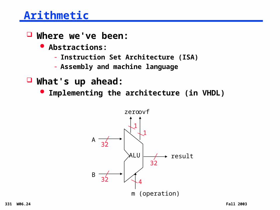
Arithmetic
Where we've been: Abstractions:
- Instruction Set Architecture (ISA)- Assembly and machine language
What's up ahead: Implementing the architecture (in VHDL)
32
32
32
m (operation)
result
A
B
ALU
4
zero ovf
11
331 W06.25 Fall 2003
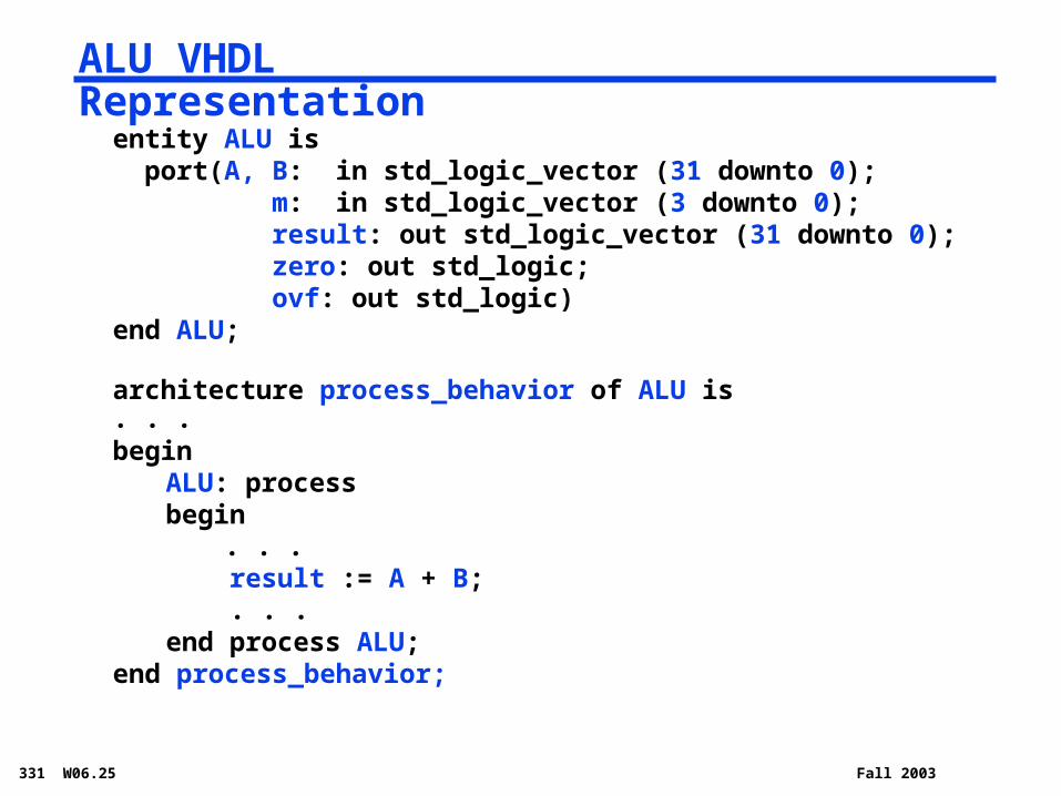
ALU VHDL Representation
entity ALU is port(A, B: in std_logic_vector (31 downto 0);
m: in std_logic_vector (3 downto 0); result: out std_logic_vector (31 downto 0); zero: out std_logic; ovf: out std_logic)
end ALU;
architecture process_behavior of ALU is. . .begin
ALU: processbegin
. . . result := A + B; . . .end process ALU;
end process_behavior;
331 W06.26 Fall 2003
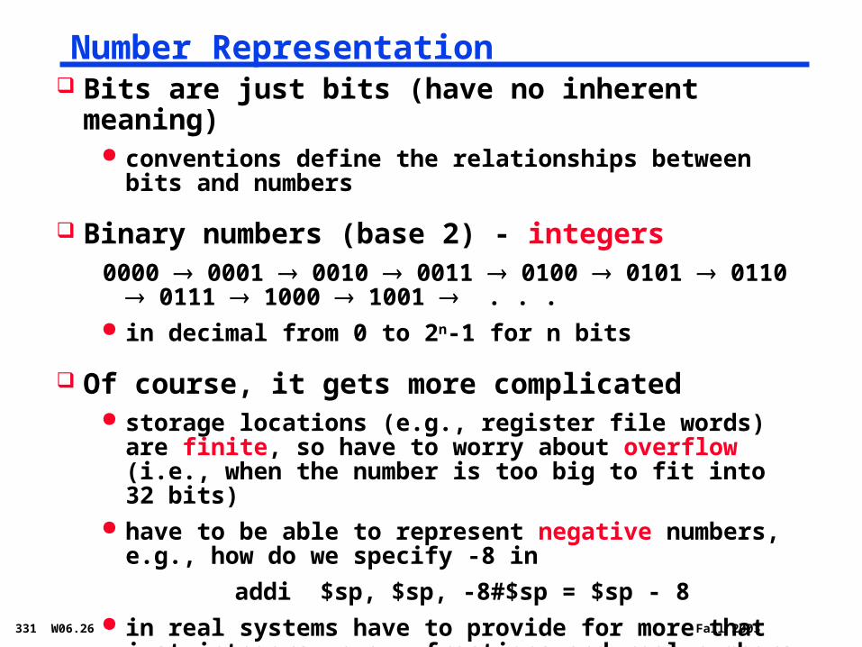
Number Representation Bits are just bits (have no inherent meaning)
conventions define the relationships between bits and numbers
Binary numbers (base 2) - integers0000 0001 0010 0011 0100 0101 0110 0111
1000 1001 . . . in decimal from 0 to 2n-1 for n bits
Of course, it gets more complicated storage locations (e.g., register file words) are finite, so
have to worry about overflow (i.e., when the number is too big to fit into 32 bits)
have to be able to represent negative numbers, e.g., how do we specify -8 in
addi $sp, $sp, -8 #$sp = $sp - 8 in real systems have to provide for more that just integers,
e.g., fractions and real numbers (and floating point)
331 W06.27 Fall 2003
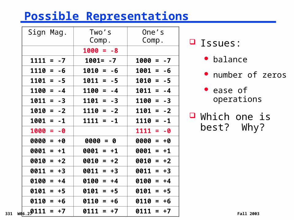
Possible RepresentationsSign Mag. Two’s Comp. One’s Comp.
1000 = -8
1111 = -7 1001= -7 1000 = -7
1110 = -6 1010 = -6 1001 = -6
1101 = -5 1011 = -5 1010 = -5
1100 = -4 1100 = -4 1011 = -4
1011 = -3 1101 = -3 1100 = -3
1010 = -2 1110 = -2 1101 = -2
1001 = -1 1111 = -1 1110 = -1
1000 = -0 1111 = -0
0000 = +0 0000 = 0 0000 = +0
0001 = +1 0001 = +1 0001 = +1
0010 = +2 0010 = +2 0010 = +2
0011 = +3 0011 = +3 0011 = +3
0100 = +4 0100 = +4 0100 = +4
0101 = +5 0101 = +5 0101 = +5
0110 = +6 0110 = +6 0110 = +6
0111 = +7 0111 = +7 0111 = +7
Issues:
balance
number of zeros
ease of operations
Which one is best? Why?
331 W06.28 Fall 2003
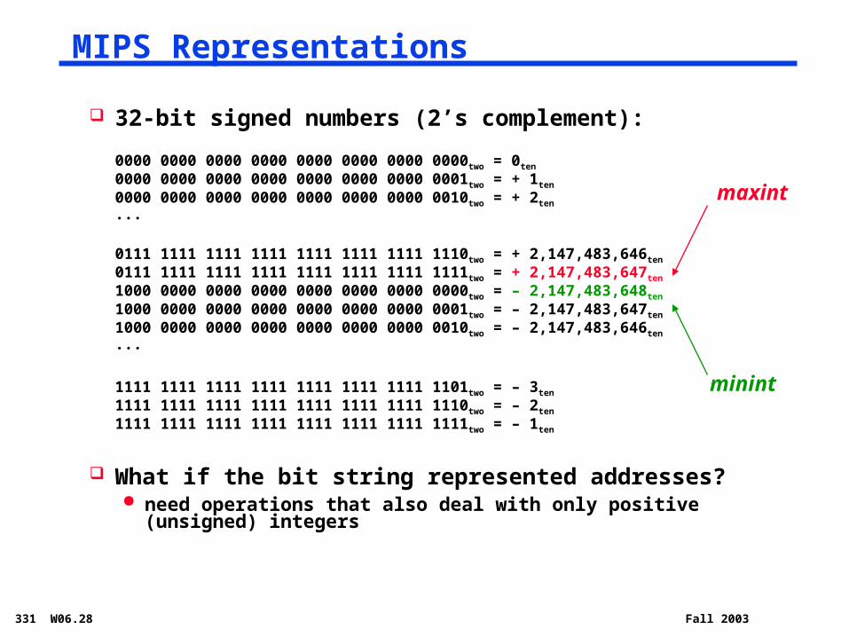
32-bit signed numbers (2’s complement):
0000 0000 0000 0000 0000 0000 0000 0000two = 0ten
0000 0000 0000 0000 0000 0000 0000 0001two = + 1ten
0000 0000 0000 0000 0000 0000 0000 0010two = + 2ten
...
0111 1111 1111 1111 1111 1111 1111 1110two = + 2,147,483,646ten0111 1111 1111 1111 1111 1111 1111 1111two = + 2,147,483,647ten
1000 0000 0000 0000 0000 0000 0000 0000two = – 2,147,483,648ten
1000 0000 0000 0000 0000 0000 0000 0001two = – 2,147,483,647ten1000 0000 0000 0000 0000 0000 0000 0010two = – 2,147,483,646ten...
1111 1111 1111 1111 1111 1111 1111 1101two = – 3ten
1111 1111 1111 1111 1111 1111 1111 1110two = – 2ten
1111 1111 1111 1111 1111 1111 1111 1111two = – 1ten
What if the bit string represented addresses? need operations that also deal with only positive (unsigned) integers
maxint
minint
MIPS Representations
331 W06.29 Fall 2003
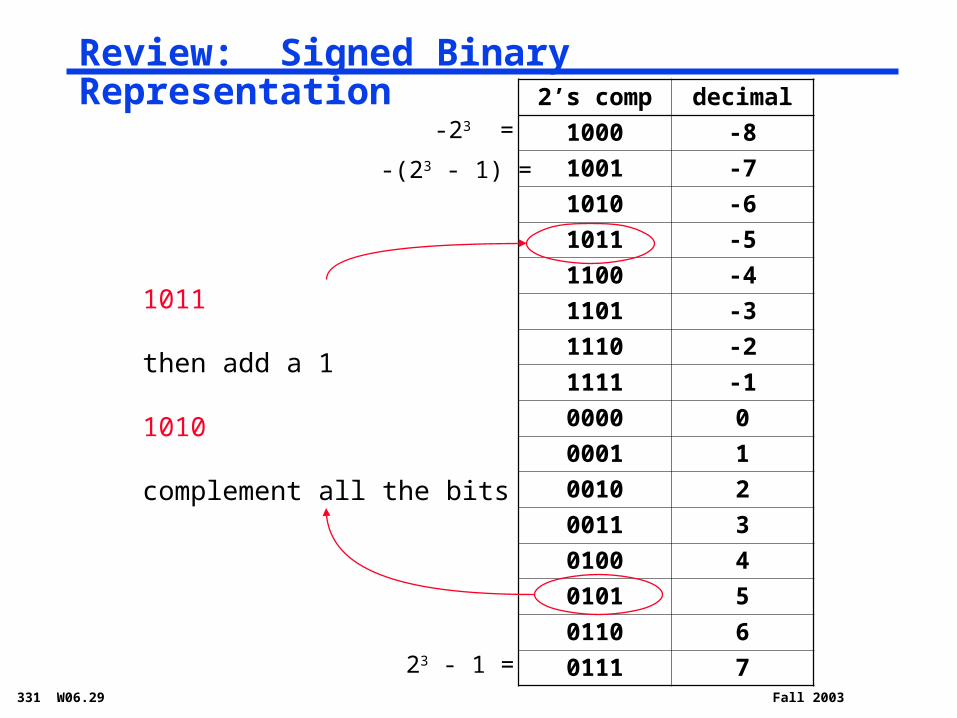
Review: Signed Binary Representation2’s comp decimal
1000 -8
1001 -7
1010 -6
1011 -5
1100 -4
1101 -3
1110 -2
1111 -1
0000 0
0001 1
0010 2
0011 3
0100 4
0101 5
0110 6
0111 723 - 1 =
1011
then add a 1
1010
complement all the bits
-(23 - 1) =
-23 =

331 W06.30 Fall 2003
Negating a two's complement number: complement
all the bits and add a 1
remember: “negate” and “invert” are quite different!
Converting n-bit numbers into numbers with more
than n bits:
MIPS 16-bit immediate gets converted to 32 bits for arithmetic
copy the most significant bit (the sign bit) into the other bits
0010 -> 0000 0010
1010 -> 1111 1010
sign extension versus zero extend (lb vs. lbu)
Two's Complement Operations
331 W06.31 Fall 2003
Goal: Design a ALU for the MIPS ISA
Must support the Arithmetic/Logic operations of the ISA
Tradeoffs of cost and speed based on frequency of occurrence, hardware budget
331 W06.32 Fall 2003
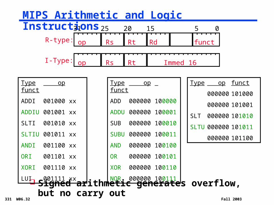
MIPS Arithmetic and Logic Instructions
Signed arithmetic generates overflow, but no carry out
R-type:
I-Type:
31 25 20 15 5 0
op Rs Rt Rd funct
op Rs Rt Immed 16
Type op funct
ADDI 001000 xx
ADDIU 001001 xx
SLTI 001010 xx
SLTIU 001011 xx
ANDI 001100 xx
ORI 001101 xx
XORI 001110 xx
LUI 001111 xx
Type op funct
ADD 000000 100000
ADDU 000000 100001
SUB 000000 100010
SUBU 000000 100011
AND 000000 100100
OR 000000 100101
XOR 000000 100110
NOR 000000 100111
Type op funct
000000 101000
000000 101001
SLT 000000 101010
SLTU 000000 101011
000000 101100

331 W06.33 Fall 2003
Design Trick: Divide & Conquer
Break the problem into simpler problems, solve them and glue together the solution
Example: assume the immediates have been taken care of before the ALU
now down to 10 operations can encode in 4 bits
00 add
01 addu
02 sub
03 subu
04 and
05 or
06 xor
07 nor
12 slt
13 sltu
331 W06.34 Fall 2003
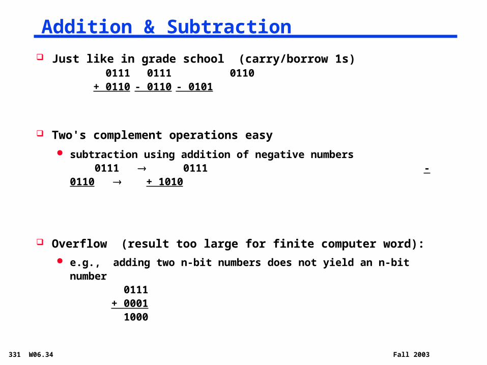
Just like in grade school (carry/borrow 1s) 0111 0111 0110+ 0110 - 0110 - 0101
Two's complement operations easy
subtraction using addition of negative numbers 0111 0111 - 0110 + 1010
Overflow (result too large for finite computer word):
e.g., adding two n-bit numbers does not yield an n-bit number 0111+ 0001 1000
Addition & Subtraction

331 W06.35 Fall 2003
Building a 1-bit Binary Adder
1 bit Full Adder
A
BS
carry_in
carry_out
S = A xor B xor carry_in
carry_out = AB v Acarry_in v Bcarry_in (majority function)
How can we use it to build a 32-bit adder?
How can we modify it easily to build an adder/subtractor?
A B carry_in carry_out S
0 0 0 0 0
0 0 1 0 1
0 1 0 0 1
0 1 1 1 0
1 0 0 0 1
1 0 1 1 0
1 1 0 1 0
1 1 1 1 1
331 W06.36 Fall 2003
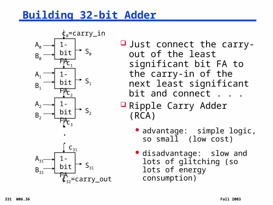
Building 32-bit Adder
1-bit FA
A0
B0
S0
c0=carry_in
c1
1-bit FA
A1
B1
S1
c2
1-bit FA
A2
B2
S2
c3
c32=carry_out
1-bit FA
A31
B31
S31
c31
. .
.
Just connect the carry-out of the least significant bit FA to the carry-in of the next least significant bit and connect . . .
Ripple Carry Adder (RCA)
advantage: simple logic, so small (low cost)
disadvantage: slow and lots of glitching (so lots of energy consumption)
331 W06.37 Fall 2003
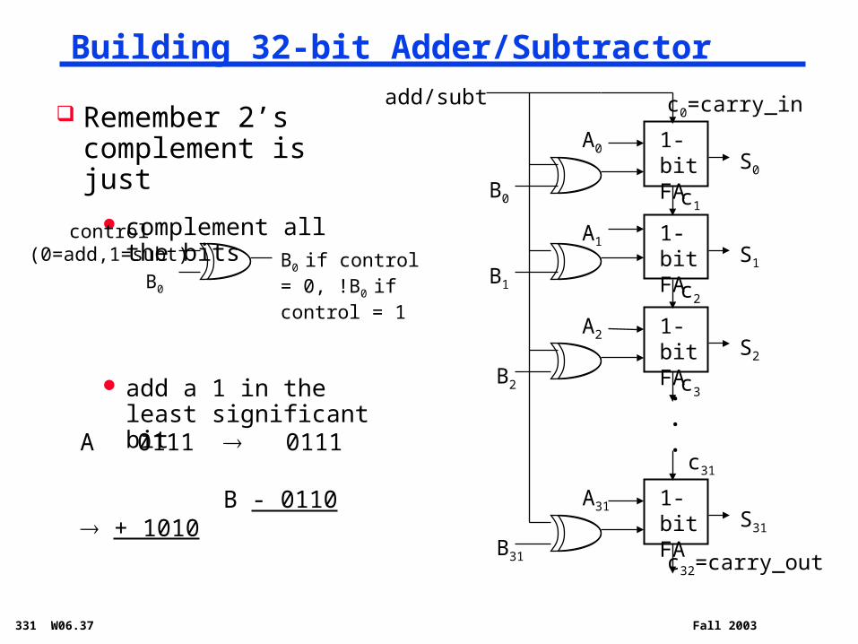
Building 32-bit Adder/Subtractor
Remember 2’s complement is just
complement all the bits
add a 1 in the least significant bit
A 0111 0111 B - 0110 + 1010
1-bit FA S0
c0=carry_in
c1
1-bit FA S1
c2
1-bit FA S2
c3
c32=carry_out
1-bit FA S31
c31
. .
.
A0
A1
A2
A31
B0
B1
B2
B31
add/subt
B0
control(0=add,1=subt) B0 if control =
0, !B0 if control = 1
331 W06.38 Fall 2003
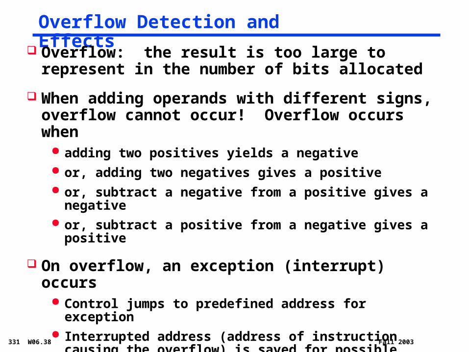
Overflow Detection and Effects
Overflow: the result is too large to represent in the number of bits allocated
When adding operands with different signs, overflow cannot occur! Overflow occurs when
adding two positives yields a negative or, adding two negatives gives a positive or, subtract a negative from a positive gives a negative or, subtract a positive from a negative gives a positive
On overflow, an exception (interrupt) occurs Control jumps to predefined address for exception Interrupted address (address of instruction causing the
overflow) is saved for possible resumption
Don't always want to detect (interrupt on) overflow

331 W06.39 Fall 2003
New MIPS Instructions
Category Instr Op Code Example Meaning
Arithmetic
(R & I format)
add unsigned 0 and 33 addu $s1, $s2, $s3 $s1 = $s2 + $s3
subt unsigned 0 and 35 subu $s1, $s2, $s3 $s1 = $s2 - $s3
add imm. unsigned
9 addiu $s1, $s2, 6 $s1 = $s2 + 6
Data Transfer
load byte unsigned
36 lbu $s1, 25($s2) $s1 = Memory($s2+25)
Cond. Branch (I & R format)
set on less than unsigned
0 and 43 sltu $s1, $s2, $s3 if ($s2<$s3) $s1=1 else $s1=0
set on less than imm. unsigned
11 sltiu $s1, $s2, 6 if ($s2<6) $s1=1 else $s1=0
Sign extend - addiu, sltiu
Zero extend - lbu
No overflow detected - addu, subu, addiu, sltu, sltiu
331 W06.40 Fall 2003
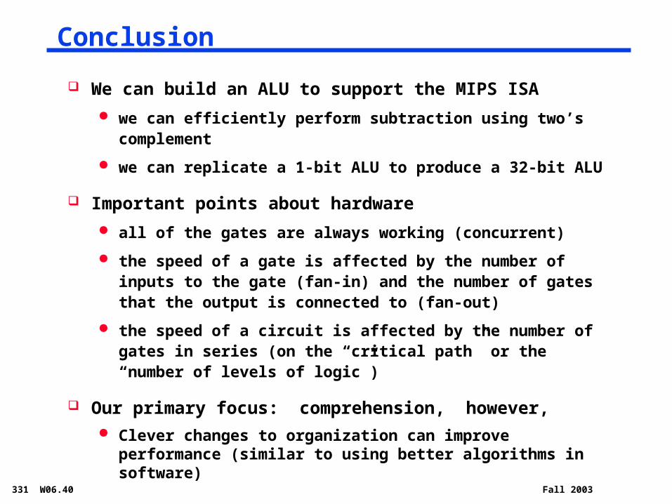
Conclusion
We can build an ALU to support the MIPS ISA
we can efficiently perform subtraction using two’s complement
we can replicate a 1-bit ALU to produce a 32-bit ALU
Important points about hardware
all of the gates are always working (concurrent)
the speed of a gate is affected by the number of inputs to the gate (fan-in) and the number of gates that the output is connected to (fan-out)
the speed of a circuit is affected by the number of gates in series (on the “critical path” or the “number of levels of logic”)
Our primary focus: comprehension, however, Clever changes to organization can improve performance
(similar to using better algorithms in software)