2110 - Thermometer teach notes V1 4 - 秋月電子通商...
24
Product information: www.kitronik.co.uk/quicklinks/2110/ Thermometer Project Teaching Notes Issue 1.4
Transcript of 2110 - Thermometer teach notes V1 4 - 秋月電子通商...

Product information: www.kitronik.co.uk/quicklinks/2110/
Thermometer Project
Teaching Notes
Issue 1.4

TEACHER Thermometer Project Kitronik Ltd
Index of sheets
Introduction
Schemes of work
Answers
The Design Process
The Design Brief
Complete Circuit
Investigation / Research
Developing a Specification
Designing the Enclosure
Design
Design Review (group task)
Soldering In Ten Steps
Resistors
Thermistors
Build Instructions
Checking Your Thermometer PCB
Testing the PCB
Adding a power switch
How the Thermometer Works
Evaluation
Improvements
Packaging Design

TEACHER Thermometer Project Kitronik Ltd
Introduction
About the project kit This project kit has been carefully designed for use by teachers in KS3 / KS4 design and technology. They are designed such that even teachers with a limited knowledge of electronics should have no trouble using them as basis around which to form a scheme of work. The project kits can be used in two ways. 1. On their own as a way of introducing electronics and electronic construction to their students
over a short number of lessons. 2. As part of a larger project involving all aspects of a product design, such as designing an
enclosure for the electronics to fit into. This booklet contains a wealth of material to aid the teacher in either case.
Using the booklet This booklet is intended as an aid for teachers when planning and implementing their scheme of work. The booklet is split into two sections. The first of these covers information specifically designed to support the teacher. The second section contains information designed to form the basis around which lessons can be planned. The teacher can choose to use this in our suggested pre-planned way, or is free to pick and choose as they see fit. Please feel free to print any pages of this booklet to use as student handouts in conjunction with Kitronik project kits. There are no page numbers in this booklet. This means you can feel free to pick and choose which sheets you use whilst still retaining a feeling of continuity.
Fault finding flow charts Fault finding flow charts have been provided for use by both teacher and students. Please note that if there are multiple faults on a complete board these flow charts may not be able to accurately identify the causes.
Support and resources You can also find resources at www.kitronik.co.uk. There are component fact sheets, information on calculating resistor and capacitor values, puzzles and much more. Kitronik provide a next day response technical assistance service via e-mail. If you have any questions regarding this kit or even suggestions for improvements please e-mail us at: Alternatively phone us on 0845 8380781.

TEACHER Thermometer Project Kitronik Ltd
Schemes of work We have developed various schemes of work for which the project kits can be used. Included within the main scheme are the areas of the National Curriculum Program of Study that it fulfils. Equally, feel free to use the material as you see fit to develop your own schemes. Before starting we would advise you to build a kit yourself. This will allow you to become familiar with the project and will provide a unit to demonstrate.
Complete product design project including electronics and enclosure Hour 1 Introduce the task using ‘The Design Brief’ sheet. Demonstrate a built unit. Take students
through the design process using ‘The Design Process’ sheet. Homework: Collect examples of electronic products & thermometers. List the common features of these products.
Hour 2 Develop a specification for the project using the ‘Developing a Specification’ sheet. Resource: Samples of products that are similar to thermometers. Homework: Using the internet or other search method find out what is meant by design for manufacture. List five reasons why design for manufacture should be considered on any design project.
Hour 3 Read the ‘Designing the Enclosure’ sheet. Develop product design using the ‘Design’ sheet. Homework: Complete design.
Hour 4 Using cardboard get the students to model their enclosure design. Allow them to make alterations to their design if the model shows any areas that need changing.
Hour 5 Split the students into groups and get them to perform a group design review using the ‘Design Review’ sheet.
Hour 6 Using the ‘How to solder’ sheet demonstrate and get students to practice soldering. Start the ‘Resistors’ work sheet. Homework: Complete any of the remaining resistor tasks.
Hour 7 Build the electronic kit using the ‘Build Instructions’. Homework: Read the ‘thermistor’ sheet.
Hour 8 Complete the build of the electronic kit. Check the completed PCB and fault find if required using ‘Checking Your thermometer PCB’ and fault finding flow charts. Homework: Read the ‘How the thermometer works’ sheet.
Hour 9 Build enclosure. Hour 10 Build enclosure. Hour 11 Build enclosure. Hour 12 Using the ‘Evaluation’ and ‘Improvement’ sheets, get the students to evaluate their final
product and state where improvements can be made. Additional Work Package design for those who complete ahead of others. National Curriculum fulfilment (England) Designing and making 1.1: a, b, d. Creativity1.3: a, c. Critical evaluation 1.4: a, b, c. Key processes 2: a, b, c, d, e, f, g, h. Range and content 3: b, c, e, j, l, m, o. Curriculum opportunities 4: a, b, c.

TEACHER Thermometer Project Kitronik Ltd
Electronics only Hour 1 Introduction to the kit demonstrating a built unit. Using the ‘How to solder’ sheet practice
soldering. Hour 2 Build the kit using the ‘Build Instructions’. Hour 3 Check the completed PCB and fault find if required using ‘Checking Your Thermometer
PCB’ and fault finding flow charts.
Answers
Resistor questions
1st Band 2nd Band Multiplier x Value Brown Black Yellow 100,000 Ω Green Blue Brown 560 Ω Brown Grey Yellow 180,000Ω
Orange White Black 39Ω
Value 1st Band 2nd Band Multiplier x 180 Ω Brown Grey Brown
3,900 Ω Orange White Red 47,000 (47K) Ω Yellow Violet Orange
1,000,000 (1M) Ω Brown Black Green
Thermometer Project
Kitronik Ltd
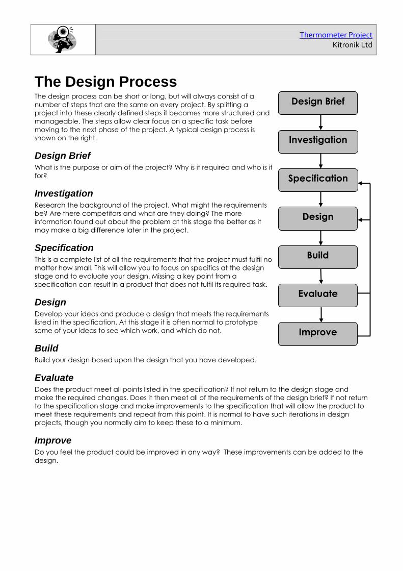
The Design Process The design process can be short or long, but will always consist of a number of steps that are the same on every project. By splitting a project into these clearly defined steps it becomes more structured and manageable. The steps allow clear focus on a specific task before moving to the next phase of the project. A typical design process is shown on the right.
Design Brief What is the purpose or aim of the project? Why is it required and who is it for?
Investigation Research the background of the project. What might the requirements be? Are there competitors and what are they doing? The more information found out about the problem at this stage the better as it may make a big difference later in the project.
Specification This is a complete list of all the requirements that the project must fulfil no matter how small. This will allow you to focus on specifics at the design stage and to evaluate your design. Missing a key point from a specification can result in a product that does not fulfil its required task.
Design Develop your ideas and produce a design that meets the requirements listed in the specification. At this stage it is often normal to prototype some of your ideas to see which work, and which do not.
Build Build your design based upon the design that you have developed.
Evaluate Does the product meet all points listed in the specification? If not return to the design stage and make the required changes. Does it then meet all of the requirements of the design brief? If not return to the specification stage and make improvements to the specification that will allow the product to meet these requirements and repeat from this point. It is normal to have such iterations in design projects, though you normally aim to keep these to a minimum.
Improve Do you feel the product could be improved in any way? These improvements can be added to the design.
Design Brief
Investigation
Specification
Design
Build
Evaluate
Improve
Thermometer Project
Kitronik Ltd
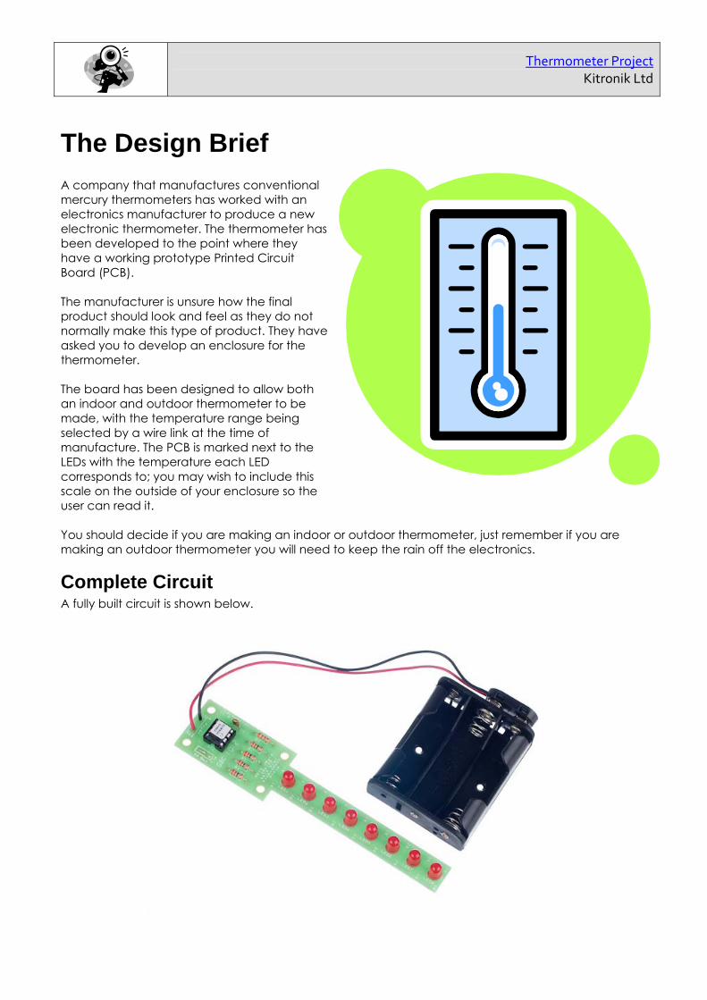
The Design Brief A company that manufactures conventional mercury thermometers has worked with an electronics manufacturer to produce a new electronic thermometer. The thermometer has been developed to the point where they have a working prototype Printed Circuit Board (PCB). The manufacturer is unsure how the final product should look and feel as they do not normally make this type of product. They have asked you to develop an enclosure for the thermometer. The board has been designed to allow both an indoor and outdoor thermometer to be made, with the temperature range being selected by a wire link at the time of manufacture. The PCB is marked next to the LEDs with the temperature each LED corresponds to; you may wish to include this scale on the outside of your enclosure so the user can read it. You should decide if you are making an indoor or outdoor thermometer, just remember if you are making an outdoor thermometer you will need to keep the rain off the electronics.
Complete Circuit A fully built circuit is shown below.

Thermometer Project
Kitronik Ltd
Investigation / Research Using a number of different search methods find examples of thermometers or similar products that are already on the market. Use additional pages if required. Name……………………………………………………………… Class………………………………
Thermometer Project
Kitronik Ltd
Developing a Specification Using your research into the target market for the product identify the key requirements for the product and explain why each of these is important. Name………………………………………………………………… Class……………………………… Requirement Reason Example: It should have a weather proof enclosure.
Example: So that it can be used outside without the electronic components getting damaged.

Thermometer Project Kitronik Ltd
Designing the Enclosure When you design the enclosure, you will need to consider: The size of the PCB (see below) Where the LEDs are mounted & how big they are
(see below) The size of the battery holder (shown right) These technical drawings of the thermometer PCB & battery cage should help you plan this. All dimensions are in mm. The LEDs are 5mm in diameter and 9mm tall. The mounting holes are 3.3mm in diameter.
Enclosure Prototype Using cardboard, foam or anything else that is suitable, make a prototype of your enclosure design. This will give you the chance of changing any aspects of the design that do not work as well as expected.
P.C.B
SPACER
ENCLOSURE
2 X M3 BOLTS
Mounting the PCB to the enclosure The drawing to the left shows how a hex spacer can be used with two bolts to fix the PCB to the enclosure. Your PCB has four mounting holes designed to take M3 bolts.
Top tip If your design of enclosure needs the LEDs to be higher, you can get LED spacers. Or why not make your own by simply cutting a drinking straw to size.
47
57
25
29
8 63.5

Thermometer Project Kitronik Ltd
Design Develop your ideas to produce a number of sketched concept designs. Then choose one of these designs and develop it further, checking it meets the requirements listed in the specification. Name……………………………………………………………………… Class………………………………

Thermometer Project Kitronik Ltd
Design Review (group task) Split into groups of three or four. Take it in turns to review each person’s design against the requirements of their specification. Also look to see if you can spot any additional aspects of their design that may cause problems with the final product. This will allow you to ensure you have a good design and catch any faults early in the design process. Note each point that is made and the reason behind it. Decide if you are going to accept the comment made. Use these points to make improvements to your initial design. Comment Reason for comment Accept or Reject
Thermometer Project Kitronik Ltd
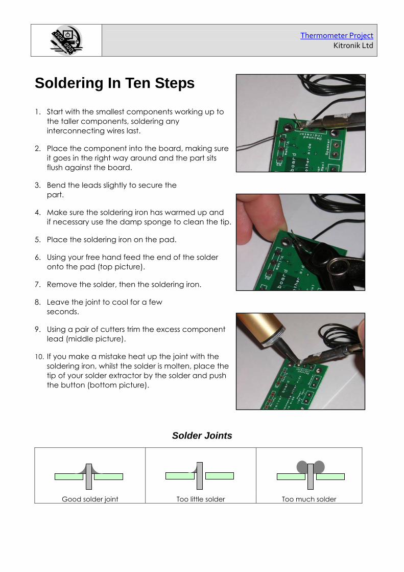
Soldering In Ten Steps
1. Start with the smallest components working up to the taller components, soldering any interconnecting wires last.
2. Place the component into the board, making sure it goes in the right way around and the part sits flush against the board.
3. Bend the leads slightly to secure the part.
4. Make sure the soldering iron has warmed up and if necessary use the damp sponge to clean the tip.
5. Place the soldering iron on the pad.
6. Using your free hand feed the end of the solder onto the pad (top picture).
7. Remove the solder, then the soldering iron.
8. Leave the joint to cool for a few seconds.
9. Using a pair of cutters trim the excess component lead (middle picture).
10. If you make a mistake heat up the joint with the soldering iron, whilst the solder is molten, place the tip of your solder extractor by the solder and push the button (bottom picture).
Solder Joints
Good solder joint Too little solder Too much solder

Thermometer Project
Kitronik Ltd
Resistors A resistor is a device that opposes the flow of electrical current. The bigger the value of a resistor the more it opposes the current flow. The value of a resistor is given in Ω (ohms) and is often referred to as its ‘resistance’.
Identifying resistor values
Band Colour 1st Band 2nd Band Multiplier x Tolerance
Silver 100 10% Gold 10 5% Black 0 0 1 Brown 1 1 10 1% Red 2 2 100 2%
Orange 3 3 1000 Yellow 4 4 10,000 Green 5 5 100,000 Blue 6 6 1,000,000
Violet 7 7 Grey 8 8 White 9 9
Example: Band 1 = Red, Band 2 = Violet, Band 3 = Orange, Band 4 = Gold The value of this resistor would be: 2 (Red) 7 (Violet) x 1,000 (Orange) = 27 x 1,000
= 27,000 with a 5% tolerance (gold) = 27KΩ
Resistor identification task Calculate the resistor values given by the bands shown below. The tolerance band has been ignored.
1st Band 2nd Band Multiplier x Value Brown Black Yellow Green Blue Brown Brown Grey Yellow
Orange White Black
Too many zeros? Kilo ohms and mega ohms can be used:
1,000Ω = 1K
1,000K = 1M
Thermometer Project
Kitronik Ltd
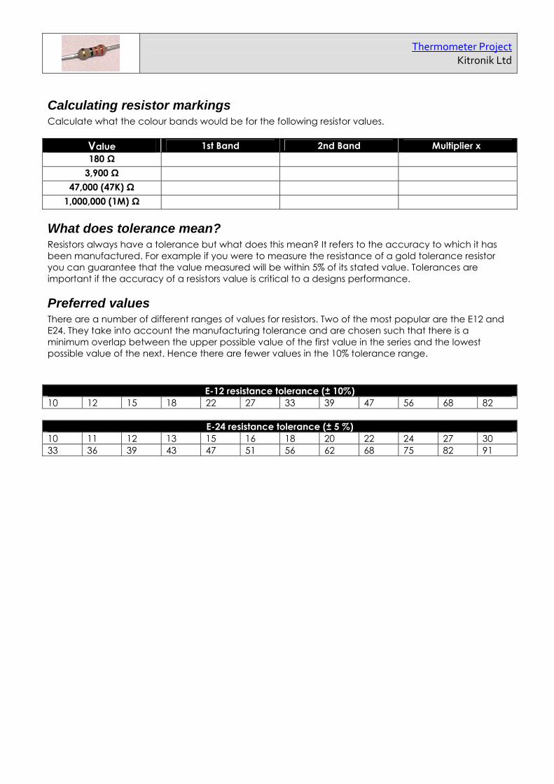
Calculating resistor markings Calculate what the colour bands would be for the following resistor values.
Value 1st Band 2nd Band Multiplier x 180 Ω
3,900 Ω 47,000 (47K) Ω
1,000,000 (1M) Ω
What does tolerance mean? Resistors always have a tolerance but what does this mean? It refers to the accuracy to which it has been manufactured. For example if you were to measure the resistance of a gold tolerance resistor you can guarantee that the value measured will be within 5% of its stated value. Tolerances are important if the accuracy of a resistors value is critical to a designs performance.
Preferred values There are a number of different ranges of values for resistors. Two of the most popular are the E12 and E24. They take into account the manufacturing tolerance and are chosen such that there is a minimum overlap between the upper possible value of the first value in the series and the lowest possible value of the next. Hence there are fewer values in the 10% tolerance range.
E-12 resistance tolerance (± 10%) 10 12 15 18 22 27 33 39 47 56 68 82
E-24 resistance tolerance (± 5 %) 10 11 12 13 15 16 18 20 22 24 27 30 33 36 39 43 47 51 56 62 68 75 82 91

Thermometer Project Kitronik Ltd
Thermistors A thermistor is a component that has a resistance that changes with temperature. There are two types of thermistor. Those with a resistance that increase with temperature (Positive Temperature Coefficient – PTC) and those with a resistance that falls with temperature (Negative Temperature Coefficient – NTC).
Temperature coefficient Most have a resistance falls as the temperatures increases (NTC). The amount by which the resistance decrease as the temperature decreases isn’t constant. It varies with temperature. A formula can be used to calculate the resistance of the thermistor at any given temperature. Normally these are calculated for you and the information can be found in the devices datasheet.
Applications There are many applications for a thermistor. Three of the most popular are listed below. Temperature sensing The most obvious application for a thermistor is to measure temperature. They are used to do this in a wide range of products such as thermostats. In rush current limiting In this application the thermistor is used to initially oppose the flow of current (by having a high resistance) into a circuit. Then as the thermistor warms up (due to the flow of electricity through the device) it resistance drops letting current flow more easily. Circuit protection In this application the thermistor is used to protect a circuit by limiting the amount of current that can flow into it. If too much current starts to flow into a circuit through the thermistor this causes the thermistor to warm up. This in turn increases the resistance of the thermistor reducing the current that can flow into the circuit.
Temperature
Resistance
Resistance decreasing with temperature

Thermometer Project Kitronik Ltd
Build Instructions Before you put any components in the board or pick up the soldering iron, just take a look at the Printed Circuit Board (PCB). The components go in the side with the writing on and the solder goes on the side with the tracks and silver pads. You will find it easiest to start with the small components and work up to the taller larger ones. If you’ve not soldered before get your soldering checked after you have done the first few joints.
Step 1 Start with the five resistors (shown right): R1 – R4 are 33 (orange, orange, black coloured bands) R5 is a 2.2K (red, red, red coloured bands) The text on the board shows where R1, R2, etc go. Make sure that you put the resistors in the right place (i.e. the 2.2K goes in to R5)
Step 2 Solder the thermistor (shown left) in to U1. It does not matter which way around it is inserted.
Step 3 Solder the Integrated Circuit (IC) holder (shown right) in to IC1. When putting this into the board, be sure to get it the right way around. The notch on the IC holder should line up with the notch on the lines marked on the PCB.
Step 4 Solder the eight Light Emitting Diodes (LED) as shown left in to LED1 – LED8. The LEDs won’t work if they don’t go in the right way around. If you look carefully one side of the LED has a flat edge, which must line up with the flat edge on the lines on the PCB.
Step 5 The thermometer has two temperature scales. One is designed for outdoor use, measuring from -10ºC to 30ºC. The other is designed for indoor use, measuring from 14ºC to 30ºC. To select the desired range a wire link (a discarded resistor lead etc) should be soldered across either the pins labeled ‘In’ for indoor, or ‘Out’ for outdoor. Step 6 The battery connector (shown right) should be soldered into the ‘Power’ terminal. The red wire must go to the + terminal and the black wire must go to the – terminal. Step 7 The IC can be put into the holder ensuring the notch on the chip lines up with the notch on the holder.

Thermometer Project Kitronik Ltd
Checking Your Thermometer PCB Check the following before you insert the batteries: Check the bottom of the board to ensure that: All holes (except the 4 large 3 mm holes) are filled with the lead of a component. All these leads are soldered. Pins next to each other are not soldered together. Check the top of the board to ensure that: The notch on the IC holder / IC is next to the indoor / outdoor selector. The flat edge of each of the LEDs matches the outline on the board. The colour bands on R5 are red, red, red. The power lead is connected the right way around (red to ‘+’, black to ‘-’).
Testing the PCB The software on the microcontroller has been specially designed to allow easy testing of the PCB. On power up the LEDs flash in turn LED1, LED2, through to LED8 for one second each. It then displays the temperature and continues to do this every ten seconds thereafter. Thirty seconds after power up a bit of the non-volatile memory is used to log the successful running of the test routine and on subsequent power ups this is not run. If your board does not function correctly when tested disconnect the power within 30 seconds of power up, otherwise you will not have the benefit of the test functionality on subsequent power ups. If the LEDs do not light in turn, or the temperature is incorrectly displayed use the fault finding flow charts to work out why.
Adding a power switch You can add either a normally closed or a normally open push button switch, which works as follows: Normally closed: When the button is pressed it goes open circuit & removes power from the
thermometer. When released it causes the software to start again and displays the temperature. In the mean time the temperature is displayed every ten seconds in any case.
Normally open: When this button is pressed the thermometer is powered and it displays the temperature. As the temperature is only shown when the button is pressed the batteries will last considerably longer with this setup.
To add the switch remove one of the power leads from the board and connect it to one of the terminals on the switch. Then use a length of wire to connect the remaining terminal on the switch to the remaining terminal on the power connection on the PCB.

Thermometer Project Kitronik Ltd
Do anyLEDslight?
No
Yes
Do allLEDs light in
sequence?
Yes
Check• The batteries are good and in the
right way around• Check the power clip is connected
the right way around and soldered correctly
• IC1 pin 1 & 8 for dry joints• IC1 is in the right way (the notch
is next to the power leads)
Do 2LEDs light at
the sametime?
Check• For dry joints on R5• R5 is a 2K2 resistor (red, red, red) • Short or dry joint on U1• For a dry joint on IC1 pin 7• For a short on IC1 pin 7 and an
adjacent pin
No
Fault finding flow chart - page 1StartPower the board up
(watch for up to 8 seconds)
Is thetemperaturedisplayed?
Yes
No - the power up sequence runs again
StopYes
No - it displays a reading but it is not right Go to page 2
No
LED(s) not working Possible cause
LED3 Dry joint on LED3
LED4 Dry joint on LED4
LEDs 1, 2, 7 & 8 Dry joint on R1Dry joint on IC1 pin5
LEDs 1 to 6 Dry joint on R2Dry joint on IC1 pin6
LEDs 3 & 4 Dry joint on R3Dry joint on IC1 pin3Short on LED3 or LED4
LEDs 5 to 8 Dry joint on R4Dry joint on IC1 pin2
Check• For a dry joint on
IC1 pin 4• The wire link on
PL1 is in the right place and for dry joints

Thermometer Project Kitronik Ltd
Fault finding flow chart - Page 2
No
Yes
StartContinued from page 1
Do two LEDsnext to each other
not light?
There is a short on one of these twoLEDs that don’t work
If LED 1 & 2 don’t work it may be ashort on IC1 between pins 5&6
Do two LEDsnext to each other
light together?
No
YesOne of these two LEDs is inbackwards
If LEDs 1 & 2 light then, later onLEDs 6 & 7 light LED2 is at fault.
Is an LEDmissing from the sequence,
but two others lightin it’s place?
There is a dryjoint on theLED that ismissing.
No
Yes
There is a shorton IC1 on pin 2or 3 and anadjacent pin

Thermometer Project Kitronik Ltd
How the Thermometer Works
Calculating the temperature At the heart of the electronic circuit is a microcontroller. A microcontroller is in effect a small computer. One of the inputs to the PIC used is capable of measuring different voltage levels that are fed into it. This is called an analogue input. It is this functionality and the variation in resistance of the thermistor with temperature that are used to calculate the temperature. The thermistor (U1) has been connected in series with a 2.2KΩ resistor R5 to form what is called a potential divider. Either end of the potential divider is connected between V+ (the positive battery voltage) and 0V. A feed is then taken from the connecting point of R5 to U1 and fed into the PIC’s analogue input (pin 7). The voltage fed to pin 7 is determined by the ratio of the resistance of the thermistor (U1) and R5. As the temperature changes and therefore the resistance of thermistor changes the voltage on pin 7 changes. It is this voltage level that is used by the PIC to calculate the temperature.
Displaying the temperature Once the PIC has calculated the temperature that must be displayed it has to light up the corresponding LED’s. The circuit uses a clever design to allow eight LED’s to be connected to only four outputs. This is known as multiplexing LEDs. Normally the output pins of the PIC are set such that no LEDs can be on (the PIC pins are set as inputs). When an LED needs to be turned on the two pins to which is connected are set to outputs and driven such that there is a voltage across the LED in the correct direction. For example to turn LED1 on, pin 5 on the PIC needs to be set high and pin 6 set low. LED2 will not be on when this happens as the voltage across it is in the wrong direction for current to flow. The value of resistors R1-R4 is 33. These resistors limit the current that can flow through the LED’s. This protects the LEDs and controls their brightness.

Thermometer Project Kitronik Ltd
Evaluation It is always important to evaluate your design once it is complete. This will ensure that it has meet all the requirements defined in the specification. In turn this should ensure that the design fulfils the design brief. Task: Check your design meets all the points listed in your specification. Task: Show your product to another person (in real life this person should be the kind of person at which the product is aimed). Get them to identify aspects of the design, which they like and aspects that they feel could be improved. Good aspects of the design Areas that could be improved
Improvements Every product on the market is constantly subject to redesign and improvement. What aspects of your design do you feel you could improve? List the aspects that could be improved and where possible draw a sketch showing the changes that you would make.

Thermometer Project Kitronik Ltd
Packaging Design If your product is to be sold to the public through the internet and delivered by mail what requirements would the packaging have? List these giving the reason for the requirement. Requirement Reason
Develop a packaging design for your product that meets these requirements. Use additional pages if required.

Reordering information Description Stock code Thermometer kit 2110
Sales Phone: 0845 8380781 Fax: 0845 8380782 Email:
Technical support Email: Phone: 0845 8380781
Every effort has been made to ensure that these notes are correct, however Kitronik accept no
responsibility for issues arising from errors / omissions in the notes.
Kitronik Ltd - Any unauthorised copying / duplication of this booklet or part thereof for purposes except for use with Kitronik project kits is not allowed without Kitronik’s prior consent.