207 Lab Report Summer 2014-2015 Experiment No.: 1139.141.9.54/207/Fall-16-17/cc1.pdf · 207 Lab...
9
Kuwait University College of Engineering & Petroleum Electrical Engineering Department 207 Lab Report Summer 2014-2015 Experiment No.: 1 Title: Ohm’s Low 10 بالكشفسلمسل ال محمد محمد محمد محمدربي رباعيسم بالع ا9 رقم البنش12000000005 لجامعي الرقم ا207/1 شعبة24/5/2015 لتاريخ اثاءحد والث ا اليوم1-3.40 الوقت المهندس إسم
-
Upload
doankhuong -
Category
Documents
-
view
215 -
download
2
Transcript of 207 Lab Report Summer 2014-2015 Experiment No.: 1139.141.9.54/207/Fall-16-17/cc1.pdf · 207 Lab...
Kuwait University
College of Engineering & Petroleum
Electrical Engineering Department
207 Lab Report
Summer 2014-2015
Experiment No.: 1
Title: Ohm’s Low
اإلسم بالعربي رباعي محمد محمد محمد محمد المسلسل بالكشف 10
الرقم الجامعي 12000000005 رقم البنش 9
شعبة 207/1
التاريخ 24/5/2015
اليوم االحد والثالثاء
الوقت 1-3.40
إسم المهندس
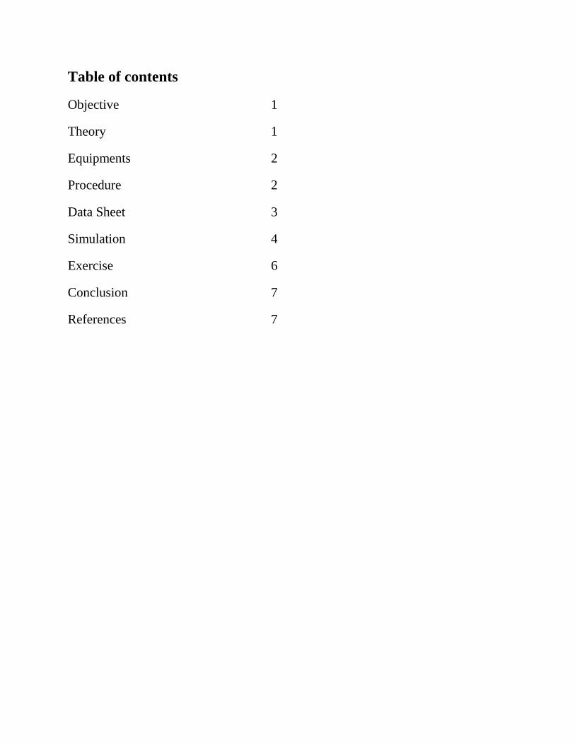
Table of contents
Objective 1
Theory 1
Equipments 2
Procedure 2
Data Sheet 3
Simulation 4
Exercise 6
Conclusion 7
References 7
Experiment #1
Familiarization and Ohm’s Law
1
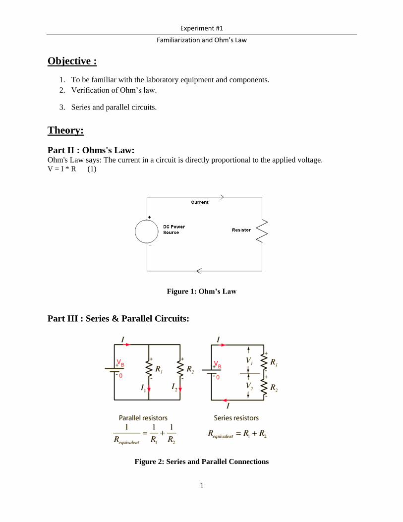
Objective :
1. To be familiar with the laboratory equipment and components.
2. Verification of Ohm’s law.
3. Series and parallel circuits.
Theory:
Part II : Ohms's Law: Ohm's Law says: The current in a circuit is directly proportional to the applied voltage. V = I * R (1)
Figure 1: Ohm’s Law
Part III : Series & Parallel Circuits:
Figure 2: Series and Parallel Connections
Experiment #1
Familiarization and Ohm’s Law
2
Equipments: 1) DC Voltage Source 2) Bread Board.
3) DMM 4) Discrete resistors
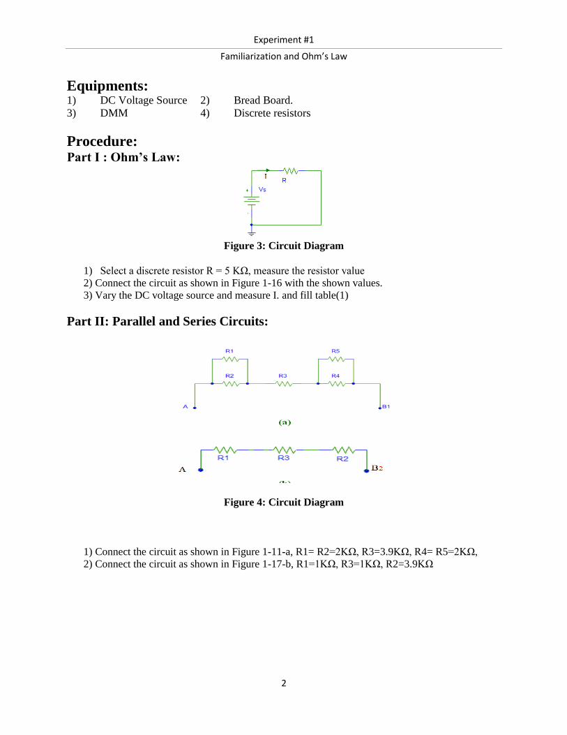
Procedure: Part I : Ohm’s Law:
Figure 3: Circuit Diagram
1) Select a discrete resistor R = 5 KΩ, measure the resistor value
2) Connect the circuit as shown in Figure 1-16 with the shown values.
3) Vary the DC voltage source and measure I. and fill table(1)
Part II: Parallel and Series Circuits:
Figure 4: Circuit Diagram
1) Connect the circuit as shown in Figure 1-11-a, R1= R2=2KΩ, R3=3.9KΩ, R4= R5=2KΩ,
2) Connect the circuit as shown in Figure 1-17-b, R1=1KΩ, R3=1KΩ, R2=3.9KΩ

Experiment #1
Familiarization and Ohm’s Law
3
Data Sheet :
Part I:
R Measured = 5.032 kΩ
Table(1)
VS
I (mA)
Theoretical (PSpice) Practical (Measured)
2 0.4 0.414
4 0.8 0.813
6 1.2000 1.206
8 1.6000 1.601
10 2.000 2.004
Part II:
RAB1 (kΩ) RAB2 (kΩ)
Theoretical
(PSpice)
Practical
(Measured)
Theoretical
(PSpice)
Practical
(Measured)
5.8 5.843 5.8 5.834
Experiment #1
Familiarization and Ohm’s Law
4
Simulation :
Part 1:
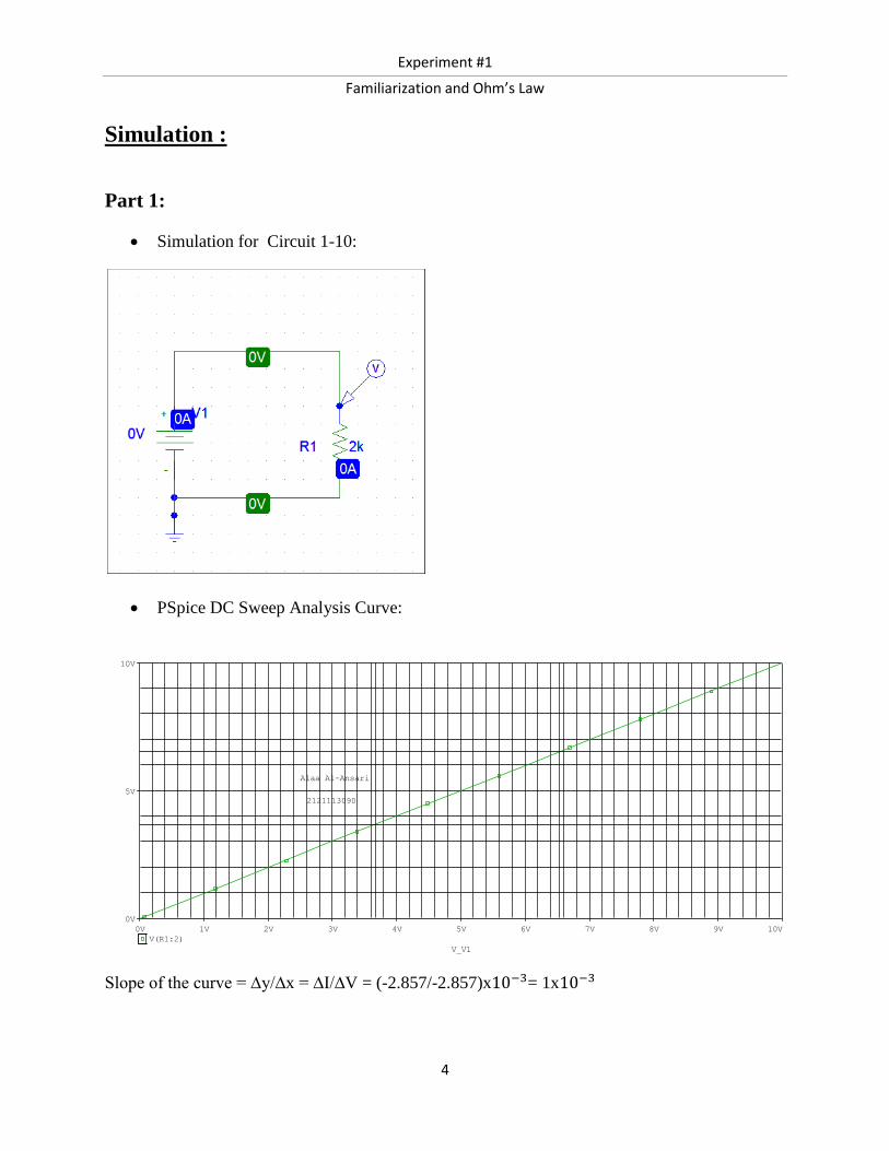
Simulation for Circuit 1-10:
PSpice DC Sweep Analysis Curve:
Slope of the curve = ∆y/∆x = ∆I/∆V = (-2.857/-2.857)x10−3= 1x10⁻³
V_V1
0V 1V 2V 3V 4V 5V 6V 7V 8V 9V 10V
V(R1:2)
0V
5V
10V
2121113090
Alaa Al-Ansari

Experiment #1
Familiarization and Ohm’s Law
5
Part II:
Simulation for circuit of Figure 1-11-a
R AB1 = 𝑽𝒔
𝑰 = (10)/(1.695)= 5.8 kΩ
Simulation for circuit of Figure 1-12-b
R AB2 = 𝑽𝒔
𝑰 = (10)/(1.695)=5.89 kΩ
Experiment #1
Familiarization and Ohm’s Law
6
Exercise :
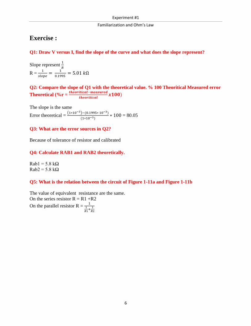
Q1: Draw V versus I, find the slope of the curve and what does the slope represent?
Slope represent 1
𝑅
R = 1
𝑠𝑙𝑜𝑝𝑒=
1
0.1995 = 5.01 𝑘Ω
Q2: Compare the slope of Q1 with the theoretical value. % 100 Theoritical Measured error
Theoretical (%r = 𝒕𝒉𝒆𝒐𝒓𝒊𝒕𝒊𝒄𝒂𝒍−𝒎𝒆𝒂𝒔𝒖𝒓𝒆𝒅
𝒕𝒉𝒆𝒐𝒓𝒊𝒕𝒊𝒄𝒂𝒍𝒙𝟏𝟎𝟎)
The slope is the same
Error theoretical = (1∗10−3)−(0.1995∗ 10−3)
(1∗10−3)∗ 100 = 80.05
Q3: What are the error sources in Q2?
Because of tolerance of resistor and calibrated
Q4: Calculate RAB1 and RAB2 theoretically.
Rab1 = 5.8 kΩ
Rab2 = 5.8 kΩ
Q5: What is the relation between the circuit of Figure 1-11a and Figure 1-11b
The value of equivalent resistance are the same.
On the series resistor R = R1 +R2
On the parallel resistor R = 1
1
𝑅1+
1
𝑅2

Experiment #1
Familiarization and Ohm’s Law
7
Conclusion :
- To generate a variable DC voltage we have to use DC power supply
- The relation between voltage and the current is not inversely (as voltage increase the
current increase too )
- On the parallel resistors :
a) V is constant
b) I(equivalent) = I1 + 12
c) R(equivalent) = R = 1
1
𝑅1+
1
𝑅2
(smaller than the smallest value of resistor on the circuit)
- On the series resistors :
a) I is constant
b) V (equivalent) = V1+ V2
c) R(equivalent )= R1 +R2 (bigger than the biggest value of resistor on the circuit.
References:
1) Fundamental of Electrical circuits Lab manual.