2014 Engineering Design Manual for Water and Sewer Facilities
44
Engineering Design Manual for Water and Sewer Facilities Prepared by: Water Resources Engineering Division 408 North Adams Street Tallahassee, Florida 32301 July 2014
Transcript of 2014 Engineering Design Manual for Water and Sewer Facilities

EngineeringDesignManualfor
WaterandSewerFacilities
Preparedby:
WaterResourcesEngineeringDivision
408NorthAdamsStreetTallahassee,Florida32301
July2014


Engineering Design for Water and Sewer Facilities
TABLE OF CONTENTS
REVISION DATE: July 2014 Engineering Design for Water and Sewer Facilities – Table of Contents
Page i of ii
Section 1 ‐ Survey Requirements ___________________________________________________ 8 Pages
1.1 Topographic Survey Requirements .......................................................................................... 1 of 8
1.1.1 General ........................................................................................................................... 1 of 8 1.1.2 Records Search ............................................................................................................... 1 of 8 1.1.3 Utility Location and Coordination .................................................................................. 1 of 8 1.1.4 Limits of Survey .............................................................................................................. 2 of 8 1.1.5 Survey Controls .............................................................................................................. 3 of 8 1.1.6 Field Data Collection ...................................................................................................... 4 of 8 1.1.7 Digital Data ..................................................................................................................... 6 of 8
1.2 Boundary Survey Requirements ............................................................................................... 6 of 8
1.2.1 General ........................................................................................................................... 6 of 8 1.2.2 Title and Record Search ................................................................................................. 7 of 8 1.2.3 Survey Controls .............................................................................................................. 7 of 8 1.2.4 Monumentation ............................................................................................................. 7 of 8 1.2.5 Field Notes ..................................................................................................................... 7 of 8
Section 2 – Water System Design ___________________________________________________ 5 Pages
2.1 Water System – General .......................................................................................................... 1 of 5
2.1.1 Scope of Work ................................................................................................................ 1 of 5 2.1.2 References ...................................................................................................................... 1 of 5
2.2 Water System – Design ............................................................................................................ 1 of 5
2.2.1 Demand Criteria ............................................................................................................. 1 of 5 2.2.2 Distribution System Sizing .............................................................................................. 3 of 5 2.2.3 Placement of Water System Piping and Appurtenances ............................................... 4 of 5 2.2.4 Thrust Restraint .............................................................................................................. 5 of 5
Section 3 – Sewer Collection System Design __________________________________________ 4 Pages
3.1 Sewer Collection System – General ......................................................................................... 1 of 4
3.1.1 Scope of Work ................................................................................................................ 1 of 4 3.1.2 References ...................................................................................................................... 1 of 4
3.2 Sewer Collection System – Design ........................................................................................... 1 of 4
3.2.1 Demand Criteria ............................................................................................................. 1 of 4 3.2.2 Collection System Sizing ................................................................................................. 2 of 4 3.2.3 Sewers ............................................................................................................................ 2 of 4 3.2.4 Manholes ........................................................................................................................ 3 of 4
Section 4 – Sewer Force Main Design _______________________________________________ 3 Pages
4.1 Sewer Force Main – General ................................................................................................... 1 of 3
4.1.1 Scope of Work ................................................................................................................ 1 of 3
Engineering Design for Water and Sewer Facilities
TABLE OF CONTENTS
REVISION DATE: July 2014 Engineering Design for Water and Sewer Facilities – Table of Contents
Page ii of ii
4.1.2 References ...................................................................................................................... 1 of 3
4.2 Sewer Force Main ‐ Design Criteria ......................................................................................... 1 of 3
4.2.1 Force Main Sizing ........................................................................................................... 1 of 3 4.2.2 Air and Vacuum Venting ................................................................................................ 2 of 3 4.2.3 Valve Locations .............................................................................................................. 2 of 3 4.2.4 Thrust Restraint .............................................................................................................. 3 of 3 4.2.5 Terminal Discharge ......................................................................................................... 3 of 3
Section 5 – Sewage Pump Station Design ____________________________________________ 4 Pages
5.1 Sewage Pump Station – General ............................................................................................. 1 of 4
5.1.1 Scope of Work ................................................................................................................ 1 of 4 5.1.2 References ...................................................................................................................... 1 of 4
5.2 Sewage Pump Station – Design ............................................................................................... 1 of 4
5.2.1 Sewage Pump Station Sizing .......................................................................................... 1 of 4 5.2.2 Location .......................................................................................................................... 1 of 4 5.2.3 Type ................................................................................................................................ 2 of 4 5.2.4 Wet Well Design ............................................................................................................. 2 of 4 5.2.5 Pumping Systems ........................................................................................................... 2 of 4 5.2.6 Valves ............................................................................................................................. 3 of 4 5.2.7 Emergency Equipment ................................................................................................... 3 of 4 5.2.8 Miscellaneous ................................................................................................................ 4 of 4
Section 6 – Reclaimed Water System Design _________________________________________ 3 Pages
6.1 Reclaimed Water System – General ........................................................................................ 1 of 3
6.1.1 Scope of Work ................................................................................................................ 1 of 3 6.1.2 References ...................................................................................................................... 1 of 3
6.2 Reclaimed Water System – Design .......................................................................................... 1 of 3
6.2.1 Reclaimed Water System Sizing ..................................................................................... 1 of 3 6.2.2 Placement of Reclaimed Water System Piping and Appurtenances ............................. 1 of 3 6.2.3 Thrust Restraint .............................................................................................................. 2 of 3
Appendix A – Recommended Guide for Utility Placement _______________________________ 1 Pages
TAUCC Recommended Guide for Utility Placement ....................................................................... 1 of 1
Appendix B – Potable Water Demand Calculation Rates ________________________________ 3 Pages
Commercial Facilities ...................................................................................................................... 1 of 3
Institutional Facilities ...................................................................................................................... 2 of 3
Residential Facilities ........................................................................................................................ 3 of 3
Engineering Design for Water and Sewer Facilities
DESIGN – SECTION 1
SURVEY REQUIREMENTS
REVISION DATE: July 2014 Design Section 1 – Survey Requirements
Page 1 of 8
1.1 Topographic Survey Requirements
1.1.1 General
The purpose of the topographic survey is to locate and document all information that is
pertinent to the design and construction of water, sewer, and reclaimed water utility
construction projects.
All firms to provide surveying services to the City of Tallahassee Underground Utilities shall have
a Florida registered Professional Land Surveyor (PLS), current and in good standing with the
Florida Board of Professional Regulation, as a full time employee to act as the Surveyor of
Record.
All surveying must be performed in accordance with the Minimum Technical Standards required
by the Florida Administrative Code under the direct supervision of the designated Surveyor of
Record. Should the Surveyor of Record become unable to perform the required duties, work on
the project will cease immediately and the City shall be notified. Any work performed on the
project when the Surveyor of Record is unavailable to perform the required duties may be
deemed unacceptable and be rejected by the City.
1.1.2 Records Search
The Surveyor of Record shall research all boundaries, subdivision plats, right‐of‐ways, easements
and other available survey elements, which may affect the physical boundaries of the project.
All the easements with book and page numbers shall be identified and labeled on the survey.
Research shall include all public record resources, which may include the following:
• City and County public records;
• Florida Department of Transportation (FDOT) right‐of‐way records;
Private utility service providers records for gas, telephone, electric, cable, fiber optics, and
other utilities; and
Ownership or Easement Records, as available.
1.1.3 Utility Location and Coordination
The Surveyor of Record shall request a design ticket from the Sunshine State One Call of Florida,
Inc. (Sunshine 811) to determine which utility service providers are located within the project
boundary, then contact each utility representative to determine the location of their utility
infrastructure so that it may be identified in the survey.

Engineering Design for Water and Sewer Facilities
DESIGN – SECTION 1
SURVEY REQUIREMENTS
REVISION DATE: July 2014 Design Section 1 – Survey Requirements
Page 2 of 8
1.1.4 Limits of Survey
For easements, the topographic survey shall extend at least 10‐feet beyond the minimum
easement width for the full length of the alignment, as shown in Figure 1.
Figure 1 – Typical Survey Limits for Easements (SAMPLE)
For streets and public rights‐of‐way, the topographic survey shall extend at least 10‐feet beyond
the right‐of‐way for the full length of the alignment, and at least 30‐feet beyond the right‐of‐
way on all side streets and terminal ends of the survey, as shown in Figure 2.
(THE REMAINDER OF THIS PAGE LEFT INTENTIONALLY BLANK)

Engineering Design for Water and Sewer Facilities
DESIGN – SECTION 1
SURVEY REQUIREMENTS
REVISION DATE: July 2014 Design Section 1 – Survey Requirements
Page 3 of 8
Figure 2 – Typical Survey Limits for Streets and Public Rights‐of‐Way (SAMPLE)
1.1.5 Survey Controls
1.1.5.1 Horizontal Control
The horizontal datum is North American Datum 1983 (NAD83), with 1990 Florida
adjustment (NAD83/90); or for Global Positioning System (GPS) survey control, the
horizontal datum is NAD83, with the National Spatial Reference System (NSRS) 2007
National Readjustment (NAD83/NSRS2007), as defined by the National Geodetic Survey
(NGS). The applicable State Plane Coordinate zone is Florida North‐Zone 3576, FIPS 903.
1.1.5.2 Vertical Control
Vertical control datum is North American Vertical Datum 1988 (NAVD88), as defined by
the NGS.
1.1.5.3 Survey Baseline
Establish survey base line for linear infrastructure construction using centerline of street
or right‐of‐way. Provide survey monuments at 100‐foot intervals along the survey
baseline, including points of curvature (PC), points of tangency (PT), and points of

Engineering Design for Water and Sewer Facilities
DESIGN – SECTION 1
SURVEY REQUIREMENTS
REVISION DATE: July 2014 Design Section 1 – Survey Requirements
Page 4 of 8
intersection (PI). Use PK or MAG nails set though stainless steel discs imprinted with the
Survey of Record PLS Number and “Survey Baseline.”
1.1.5.4 Survey Benchmarks
Establish benchmarks (BMs), or control points (CPs), at each end of the project, with
intermediate locations spaced about every 500 feet. Benchmarks are to be reasonably
permanent, easily identifiable, and at a sufficient distance outside the limits of
construction so as not to be damaged or destroyed. Provide a minimum of two BMs on
each project, including northing, easting, elevation, and description information.
1.1.6 Field Data Collection
The information provided below is typical of what elements can be expected for a topographic
survey field data collection, but is not intended to be a comprehensive list. The Surveyor of
Record shall be responsible for identifying and locating all above ground features within the
limits of the survey, as well as above and below ground utilities that have been marked by
others and that may be required for design consideration.
1.1.6.1 Topography and Natural Features
Establish a spot elevation grid with sufficient data to accurately generate a 3‐
dimensional surface model with 1‐foot (maximum) contours within the limits of survey.
Locate and describe all natural features, including water bodies, wetlands, significant
slopes, and other natural features required by local Code for permitting.
1.1.6.2 Right‐of‐Way, Property Lines, and Easements
Locate and tie all existing rights‐of‐way, property lines and easements including type,
size, bearing, book and page, as necessary. Show lot, block, subdivision, and dimensions
with adjacent street names.
1.1.6.3 Roadways and Railways
Identify roadways, driveways, alleys and sidewalks with pavement type. Show
centerlines and angles of intersection of the side street(s) with main roadway centerline,
as necessary. Show all mail boxes, road signs and signal posts. Identify all existing or
abandoned railways with company names, if available.
1.1.6.4 Trees, Shrubs, Landscaping, and Hardscaping
Locate all trees, vegetation lines, landscaping, and hardscaping features. Provide
descriptions for bushes, shrubs or other landscaping plants. Provide locations and

Engineering Design for Water and Sewer Facilities
DESIGN – SECTION 1
SURVEY REQUIREMENTS
REVISION DATE: July 2014 Design Section 1 – Survey Requirements
Page 5 of 8
descriptions of other landscaping and hardscaping features such as grass lawns, gravel
beds, rock structures, sculptures, irrigation devices, etc., within the limits of the survey.
Provide common name, scientific name, tree size (diameter at breast height, DBH), and
critical protection zone (CPZ) for all trees over 2‐inches DBH, unless otherwise directed
by the City. In lieu of providing the common name, scientific name, and tree size
information graphically, the Surveyor of Record may provide a reference table with the
information above and a reference number linking the table to the tree location on the
survey. The CPZ must be shown graphically in relation to tree on the survey.
1.1.6.5 Fences and Walls
Provide locations and descriptions of all fences and walls within the limits of the survey.
1.1.6.6 Drainage Features
Provide locations and descriptions of all drainage features within the limits of the
survey. Typical features include swales, ditches, ponds, aprons, culverts, headwalls, rip‐
rap, mitered‐end sections, and other drainage features. Identify all tops of banks and
toes of slopes with elevations at sufficient intervals to define the drainage feature.
Provide size, material, and invert elevations of all culverts. Provide top and invert
elevations of all headwalls, and mitered‐end sections.
1.1.6.7 Utilities
Provide locations and descriptions, including type, size, materials, and elevations (if
possible) of all existing above and below ground utilities within the limits of the survey.
It is critical that storm and sewer manhole type (brick, precast, fiberglass, etc.), size,
and critical elevations are accurately identified and documented at the time of survey.
Digital photograph(s) shall be provided for each structure to illustrate the physical
conditions at the time of survey. The photograph shall be linked to the survey data so
that the information can be accurately cross‐referenced.
1.1.6.7.1 Water System
Typical water system features include water distribution pipe, valves, hydrants,
services, meters, and backflow devices.
Engineering Design for Water and Sewer Facilities
DESIGN – SECTION 1
SURVEY REQUIREMENTS
REVISION DATE: July 2014 Design Section 1 – Survey Requirements
Page 6 of 8
1.1.6.7.2 Wastewater Collection and Transmission Systems
Typical wastewater collection and transmission system features include collection
system piping, manholes, laterals, and cleanouts; sewer pumping stations, force
main piping, valves, and air valves.
1.1.6.7.3 Storm Drain Systems
Typical storm drain system features include storm drain piping, manholes, and
inlets. Include detailed information for special features such as baffles, skimmers,
weirs, and throat lengths.
1.1.6.7.4 Gas
Typical gas system features include piping (indicate high or low pressure, if
available), regulating facilities, valves, and meters.
1.1.6.7.5 Electric
Typical electric system features include conduits, duct banks, pedestals, pull boxes,
transformers, poles, and guy wires. Include voltage information and service
provider, if available.
1.1.6.7.6 Telephone and Cable
Typical telephone and cable system features include conduits, duct banks,
pedestals, pull boxes, and cable type and size (fiber optic, no. of pairs, etc.). Include
service providers, if available.
1.1.7 Digital Data
Produce all digital drawings in AutoCAD Civil 3D 2012 format, or newer. Provide a survey data
point file showing point number, northing/easting, elevation, and description of all survey data
points. Provide electronic plot (not scan) of final survey in Adobe PDF file format.
Boundary Survey Requirements
1.2.1 General
The purpose of the boundary survey is to locate and prepare legal descriptions for fee title
conveyance, and right‐of‐way, easement, and lease agreement acquisition or abandonment.
All firms to provide surveying services to the City of Tallahassee Underground Utilities shall have
a Florida registered Professional Land Surveyor (PLS), current and in good standing with the
Engineering Design for Water and Sewer Facilities
DESIGN – SECTION 1
SURVEY REQUIREMENTS
REVISION DATE: July 2014 Design Section 1 – Survey Requirements
Page 7 of 8
Florida Board of Professional Regulation, as a full time employee to act as the Surveyor of
Record.
All surveying must be performed in accordance with the Minimum Technical Standards required
by the Florida Administrative Code under the direct supervision of the designated Surveyor of
Record. Should the Surveyor of Record become unable to perform the required duties, work on
the project will cease immediately and the City shall be notified. Any work performed on the
project when the Surveyor of Record is unavailable to perform the required duties may be
deemed unacceptable and be rejected by the City.
1.2.2 Title and Record Search
The Surveyor of Record shall assume the responsibility for adequate title research to support
the determination of the location of intended boundaries of the land parcel surveyed. The title
must be searched back in time sufficiently far enough to uncover all of the pertinent
information. In many cases, this may be to the sovereignty of the soil. Research shall include all
public record resources, which may include the following:
• City and County public records;
• Florida Department of Transportation (FDOT) right‐of‐way records;
Private utility service providers records for gas, telephone, electric, cable, fiber optics, and
other utilities; and
Ownership or easement records.
1.2.3 Survey Controls
Use the same horizontal and vertical survey controls as those defined for topographic surveys
above.
1.2.4 Monumentation
Set monuments using a minimum of 5/8” diameter x 18” iron rods capped with Surveyor of
Record name and registration number or survey company name. The Surveyor of Record shall
determine whether Letters of Permission granting access to private property for surveying
purposes will be required. The City Project Manager shall be informed of the need for this task,
and kept informed of its progress.
1.2.5 Field Notes
Field notes, for the use in preparing a boundary survey, are worded metes and bounds
descriptions of the results of the on‐the‐ground survey of real property. Provide sufficient
information to identify the location, boundaries, monumentation, and area of the described
Engineering Design for Water and Sewer Facilities
DESIGN – SECTION 1
SURVEY REQUIREMENTS
REVISION DATE: July 2014 Design Section 1 – Survey Requirements
Page 8 of 8
tract of land, as well as the relationship to any parent tract of land or adjacent tracts.
Accompany each metes and bounds description with a drawing graphically depicting the worded
description.
END OF DESIGN SECTION 1

Engineering Design for Water and Sewer Facilities
DESIGN – SECTION 2
WATER SYSTEM DESIGN
REVISION DATE: July 2014 Design Section 2 – Water System Design
Page 1 of 5
2.1 Water System ‐ General
2.1.1 Scope of Work
Define engineering design criteria for potable water supply and distribution systems.
2.1.2 References
The design engineer is referred to the City of Tallahassee Underground Utilities Technical
Specifications for Water and Sewer Construction, which provides Contractors with product
details and installation procedures to be used when constructing water and sewer system
components. The design engineer shall be familiar with products and procedures acceptable to
the City for construction of new facilities.
Water system design shall proceed in accordance with the applicable provisions of the Florida
Department of Environmental Protection (Chapter 62‐555 F.A.C.), and AWWA Manual M31.
2.2 Water System ‐ Design
2.2.1 Demand Criteria
2.2.1.1 Average Day Demand
The average day demand is defined as the sum total volume delivered over a defined
period of time (i.e. monthly, quarterly, annually, etc.) divided by the number of days in
that time period. This rate can vary significantly monthly, seasonally, and annually
depending on factors such as weather patterns and rainfall amounts.
In the absence of verified historical data, calculate the average day demand for potable
water using the rates indicated for the types of development or establishments included
in Appendix B, assuming full build‐out or full occupancy. Include ancillary potable water
uses (i.e. irrigation, cooling water, etc.) in the calculations for the average day demand.
2.2.1.2 Maximum Day Demand
Maximum day demand is defined as the maximum quantity of water used on any day of
the year. Calculate the maximum day demand based on the average day demand, for
the size and type of development under full build‐out conditions, multiplied by an
appropriate peaking factor.
In the absence of verified historical data, maximum day demand means 1.5 times the
average daily demand of the system.

Engineering Design for Water and Sewer Facilities
DESIGN – SECTION 2
WATER SYSTEM DESIGN
REVISION DATE: July 2014 Design Section 2 – Water System Design
Page 2 of 5
2.2.1.3 Peak Hour Demand
Peak hour demand is defined as the highest hourly rate of water used during the
maximum day demand period. Calculate the peak hour demand based on the maximum
day demand, for the size and type of development under full build‐out conditions,
multiplied by an appropriate peaking factor.
In the absence of verified historical data, peak hour demand means 2.5 times the
maximum day demand of the system.
2.2.1.4 Fire Flow
Design water distribution systems in accordance with the fire protection requirements
of the Insurance Services Office (ISO), as outlined in AWWA Manual M31. For single‐
family or duplex residential development not exceeding two stories in height, meet or
exceed the following minimum fire flow criteria, while maintaining a minimum residual
system pressure greater than 20 PSI at all points in the system:
Distance Between Single‐Family
Residential Buildings (FT)
Minimum Fire Flow Rate (GPM)
Minimum Main Size (inches)
>100 500 6
31 – 100 750 8
11 – 30 1000 8
10 or less 1500 8
For multi‐family, institutional, commercial, industrial, or other special developments,
establish the water distribution system capacity to satisfy the minimum fire flow
requirements of the development in accordance with the Insurance Services Office
(ISO), and as outlined in AWWA Manual M31.
The design engineer shall be required to obtain fire hydrant flow test results to verify
available water system capacity to serve the development area. Hydrant flow tests shall
be performed in accordance with AWWA M17, latest edition. Results shall be certified
by a Florida licensed Professional Engineer or Florida licensed Fire Protection
Contractor. All hydrant flow tests shall be coordinated through the City of Tallahassee
Underground Utilities Department.

Engineering Design for Water and Sewer Facilities
DESIGN – SECTION 2
WATER SYSTEM DESIGN
REVISION DATE: July 2014 Design Section 2 – Water System Design
Page 3 of 5
2.2.2 Distribution System Sizing
Size the water distribution system in accordance with the approved master plan established for
that area. In the absence of an approved master plan, size the water distribution system to
deliver the design demand ‐ the sum of the maximum day demand plus the needed fire flow,
while maintaining a minimum residual system pressure greater than 20 PSI at all points in the
system ‐ for the full build‐out conditions.
The target maximum water system head loss is 1 foot of head loss per 1,000 feet of pipe under
average day demand conditions, using a Hazen‐William friction factor (C‐factor) of 120 for
design purposes. The target maximum fluid velocity range is 5‐8 FPS under maximum day
demand conditions. In all cases, the minimum water system pressure shall not drop below 20
PSI for the maximum day demand plus needed fire flow, or the peak hour demand.
The preferred minimum distribution system pipe size is 8‐inches, excluding cul‐de‐sacs, fire
hydrant connections, fire lines, or water services. For these exceptions, the following guidelines
shall apply:
Water mains on residential cul‐de‐sacs serving up to six single‐family homes and less
than 500 feet in length may be 6‐inches.
Water mains on residential cul‐de‐sacs serving more than six single‐family homes or
greater than 500 feet in length shall be 8‐inch minimum.
Fire hydrant connections shall be 6 inch diameter up to 50 feet in length. Hydrant
connections longer than 50 feet shall require 8‐inch diameter pipe.
Fire lines shall be sized by the design engineer for the intended application and needed
fire flow demand in accordance with Insurance Services Office (ISO), as outlined in
AWWA Manual M31.
Water services shall be sized by the design engineer for the intended application,
including irrigation demand and other incidental demands, in accordance with AWWA
Manual M22. In no case shall a water service line be smaller than 1‐inch diameter.
Make design computations using hydraulic modeling software, such as Innovyze InfoWater,
Bentley WaterCAD, or EPANet. Submit calculations/modeling results to the City of Tallahassee
Underground Utilities Development Review Coordinator for review.
Engineering Design for Water and Sewer Facilities
DESIGN – SECTION 2
WATER SYSTEM DESIGN
REVISION DATE: July 2014 Design Section 2 – Water System Design
Page 4 of 5
2.2.3 Placement of Water System Piping and Appurtenances
2.2.3.1 Piping
Install water system piping for new development in accordance with the Tallahassee
Area Utilities Coordinating Committee – Recommended Guide for Utility Placement, as
provided in the Appendix A, whenever possible. Exceptions from this guide must be
approved by the City and/or County, when applicable.
Loop the water distribution system piping, whenever possible. Avoid dead‐end water
mains, except when the design engineer can demonstrate that looping is not possible.
When required, such as in a cul‐de‐sac, dead‐end mains must have a hydrant located at
the end of the main for flushing.
2.2.3.2 Valves
Provide valves to isolate water system piping for repair and maintenance. The number
of valves provided depends on the configuration of the distribution network. Ideally,
each pipe should have at least one valve. For more critical pipes, such as those with
large number of customer or substantial demand requirements, multiple valves may be
warranted.
As a general rule, use the “N‐1” valve place scheme at junctions, where “N” is the
number of pipes at a junction (tees and crosses). For example, a tee has three pipes
connecting at the junction; therefore, two valves should be installed (3 ‐ 1=2). As a
general rule, the placement of the valves at a junction should be downstream from the
source of water.
Place valves on all new fire hydrant stubs; at both ends of all jack and bore crossings;
and at both ends of crossings of those streets classified as major collectors, arterial
roads, or with 3 or more thru lanes of traffic.
Place valves on straight runs of pipe (no branches) at intervals no greater than 500 feet
for pipe sections with customer services, or at intervals of 1,000 feet for pipe section
without customer services.
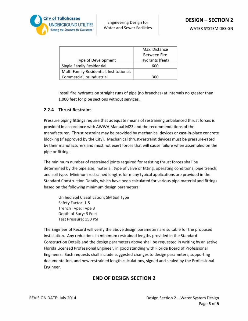
2.2.3.3 Fire Hydrants
Provide fire hydrants according to the following spacing requirements:
Engineering Design for Water and Sewer Facilities
DESIGN – SECTION 2
WATER SYSTEM DESIGN
REVISION DATE: July 2014 Design Section 2 – Water System Design
Page 5 of 5
Type of Development
Max. Distance Between Fire Hydrants (feet)
Single Family Residential 600
Multi‐Family Residential, Institutional, Commercial, or Industrial
300
Install fire hydrants on straight runs of pipe (no branches) at intervals no greater than
1,000 feet for pipe sections without services.
2.2.4 Thrust Restraint
Pressure piping fittings require that adequate means of restraining unbalanced thrust forces is
provided in accordance with AWWA Manual M23 and the recommendations of the
manufacturer. Thrust restraint may be provided by mechanical devices or cast‐in‐place concrete
blocking (if approved by the City). Mechanical thrust‐restraint devices must be pressure‐rated
by their manufacturers and must not exert forces that will cause failure when assembled on the
pipe or fitting.
The minimum number of restrained joints required for resisting thrust forces shall be
determined by the pipe size, material, type of valve or fitting, operating conditions, pipe trench,
and soil type. Minimum restrained lengths for many typical applications are provided in the
Standard Construction Details, which have been calculated for various pipe material and fittings
based on the following minimum design parameters:
Unified Soil Classification: SM Soil Type Safety Factor: 1.5 Trench Type: Type 3
Depth of Bury: 3 Feet Test Pressure: 150 PSI
The Engineer of Record will verify the above design parameters are suitable for the proposed
installation. Any reductions in minimum restrained lengths provided in the Standard
Construction Details and the design parameters above shall be requested in writing by an active
Florida Licensed Professional Engineer, in good standing with Florida Board of Professional
Engineers. Such requests shall include suggested changes to design parameters, supporting
documentation, and new restrained length calculations, signed and sealed by the Professional
Engineer.
END OF DESIGN SECTION 2

Engineering Design for Water and Sewer Facilities
DESIGN – SECTION 3
SEWER COLLECTION SYSTEM DESIGN
REVISION DATE: July 2014 Design Section 3 – Sewer Collection System Design
Page 1 of 4
3.1 Sewer Collection System ‐ General
3.1.1 Scope of Work
Define engineering design criteria for sanitary sewer collection systems.
3.1.2 References
The design engineer is referred to the City of Tallahassee Underground Utilities Technical
Specifications for Water and Sewer Construction, which provides Contractors with product
details and installation procedures to be used when constructing water and sewer system
components. The design engineer shall be familiar with products and procedures acceptable to
the City for construction of new facilities.
Sewer collection system design shall proceed in accordance with the applicable provisions of the
Florida Department of Environmental Protection (Chapter 62‐604 F.A.C.) and the most current
edition of the Recommended Standards for Wastewater Facilities, commonly referred to as
“10 States Standards.”
3.2 Sewer Collection System ‐ Design
3.2.1 Demand Criteria
3.2.1.1 Average Day Flow
Calculate the average day flow for sanitary sewer at 80 percent of the water demand
rates indicated in Appendix B.
3.2.1.2 Peak Hour Flow
Peak hour flow is defined as the highest hourly rate of wastewater flow during the
maximum day demand period. Calculate the peak hour demand based on the average
day demand, for the size and type of development under full build‐out conditions,
multiplied by an appropriate peaking factor. In the absence of verified historical data,
peak hour demand should be calculated using the following peaking factors:
Average Daily Flow Range Peak Factor
0.00 to 0.05 MGD 4.0
0.05 to 0.25 MGD 3.0
0.25 to 2.00 MGD 2.5
Engineering Design for Water and Sewer Facilities
DESIGN – SECTION 3
SEWER COLLECTION SYSTEM DESIGN
REVISION DATE: July 2014 Design Section 3 – Sewer Collection System Design
Page 2 of 4
3.2.2 Collection System Sizing
Size the sanitary sewer collection system in accordance with the approved master plan
established for that area. In the absence of an approved master plan, size the collection system
to convey the peak hour flow from the contributing area for the full build‐out conditions, plus
any flow received from other pumping stations.
The minimum nominal sewer pipe size allowed shall be 8 inches for sewer mains (mains that
serve more than one resident or facility) and 4 inches for sewer service connections.
Sewer collection system piping shall not be over‐sized in order to reduce the pipe slope.
3.2.3 Sewers
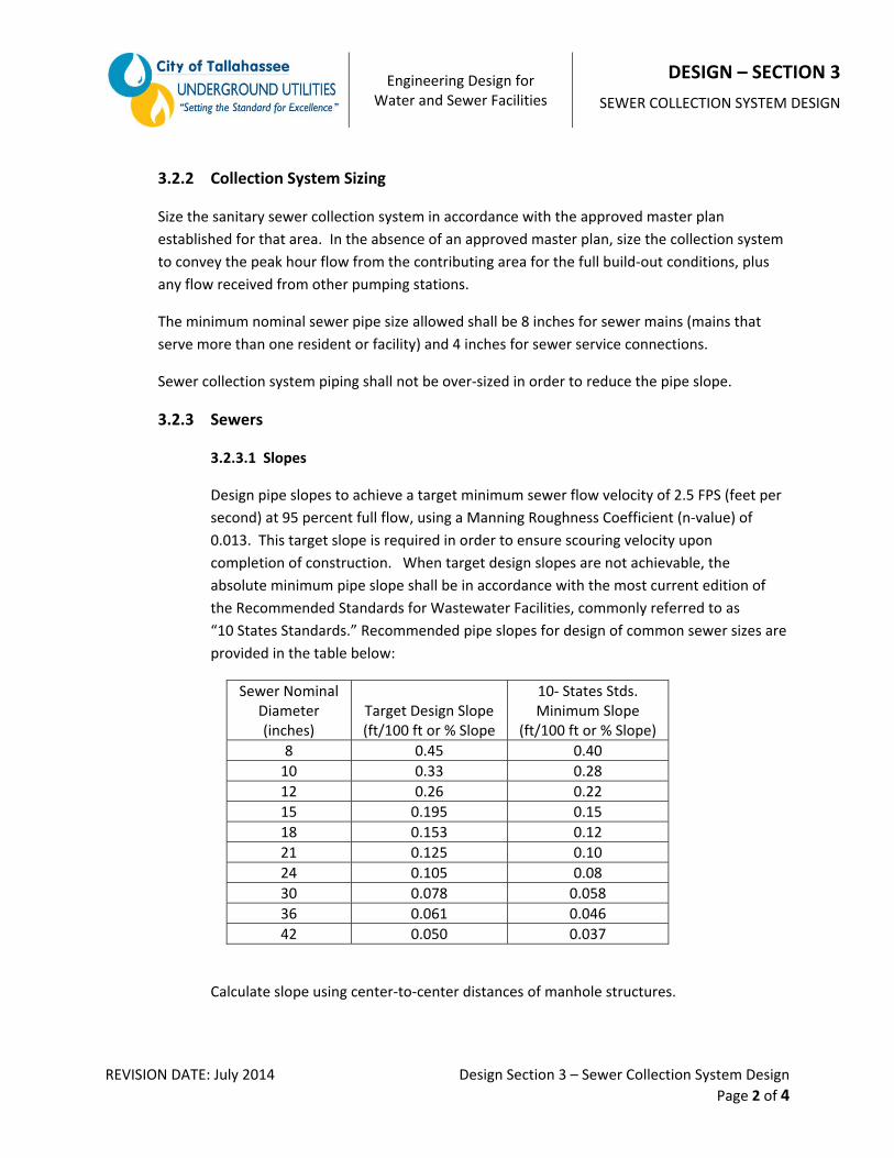
3.2.3.1 Slopes
Design pipe slopes to achieve a target minimum sewer flow velocity of 2.5 FPS (feet per
second) at 95 percent full flow, using a Manning Roughness Coefficient (n‐value) of
0.013. This target slope is required in order to ensure scouring velocity upon
completion of construction. When target design slopes are not achievable, the
absolute minimum pipe slope shall be in accordance with the most current edition of
the Recommended Standards for Wastewater Facilities, commonly referred to as
“10 States Standards.” Recommended pipe slopes for design of common sewer sizes are
provided in the table below:
Sewer Nominal Diameter (inches)
Target Design Slope (ft/100 ft or % Slope
10‐ States Stds. Minimum Slope
(ft/100 ft or % Slope)
8 0.45 0.40
10 0.33 0.28
12 0.26 0.22
15 0.195 0.15
18 0.153 0.12
21 0.125 0.10
24 0.105 0.08
30 0.078 0.058
36 0.061 0.046
42 0.050 0.037
Calculate slope using center‐to‐center distances of manhole structures.

Engineering Design for Water and Sewer Facilities
DESIGN – SECTION 3
SEWER COLLECTION SYSTEM DESIGN
REVISION DATE: July 2014 Design Section 3 – Sewer Collection System Design
Page 3 of 4
3.2.3.2 Location and Alignment
Install sewer lines for new development in accordance with the Tallahassee Area
Utilities Coordinating Committee – Recommended Guide for Utility Placement, as
provided in the Appendix A, whenever possible. Exceptions from this guide must be
approved by the City and/or County, when applicable.
Sewer lines shall be designed with straight alignment and grade between manholes.
3.2.3.3 Connections to Manholes
Where sewers connect to manholes, design the upstream sewer crown elevations to
match the downstream sewer crown elevation, when possible. When upstream sewers
cannot match the downstream crown elevation, the maximum drop between the
connecting sewer invert elevation and the manhole bench shall be less than 24 inches;
or provide an outside drop connection to the manhole.
3.1.1.1 Depth
The minimum depth of mains will be 6‐feet and the maximum depth will be 16‐feet, as
measured from finished grade above the sewer to the invert elevation of the pipe.
Exceptions to this minimum depth requirement must be approved in writing by the City.
3.1.1.2 Service Laterals
Sewer service laterals shall connect directly to the sewer main using approved sewer
fittings. Sewer service connections to manholes shall not be allowed unless approved in
writing by the City. The minimum depth of the sewer services at the property line will
be 5‐feet, with a maximum depth of 10 feet, unless otherwise approved by the City.
Cleanouts shall be provided at the right‐of‐way line for all sewer service lines. Prior to
final inspection of the sewer, the cleanout will be installed 2 feet above ground level.
After final acceptance of the sewer the cleanout shall be installed flush to grade, with an
EMS location marker buried directly next to it.
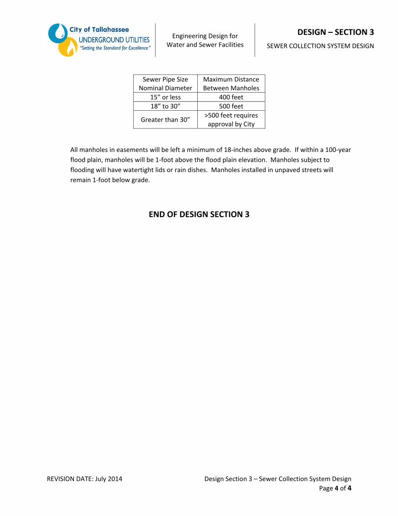
3.2.4 Manholes
Provide sanitary sewer manholes for all sewers 8 inches and larger at all roadway intersections,
sewer junctions, terminal ends, changes in alignment, changes in slope, and changes in pipe size.
Maximum distance between manholes, measured center to center, shall be as follows:
Engineering Design for Water and Sewer Facilities
DESIGN – SECTION 3
SEWER COLLECTION SYSTEM DESIGN
REVISION DATE: July 2014 Design Section 3 – Sewer Collection System Design
Page 4 of 4
Sewer Pipe Size Nominal Diameter
Maximum Distance Between Manholes
15” or less 400 feet
18” to 30” 500 feet
Greater than 30” >500 feet requires approval by City
All manholes in easements will be left a minimum of 18‐inches above grade. If within a 100‐year
flood plain, manholes will be 1‐foot above the flood plain elevation. Manholes subject to
flooding will have watertight lids or rain dishes. Manholes installed in unpaved streets will
remain 1‐foot below grade.
END OF DESIGN SECTION 3

(THISPAGELEFTINTENTIONALLYBLANK)
Engineering Design for Water and Sewer Facilities
DESIGN – SECTION 4
SEWER FORCE MAIN DESIGN
REVISION DATE: July 2014 Design Section 4 – Sewer Force Main Design
Page 1 of 3
4.1 Sewer Force Main ‐ General
4.1.1 Scope of Work
Define engineering design criteria for sewer force main systems.
4.1.2 References
The design engineer is referred to the City of Tallahassee Underground Utilities Technical
Specifications for Water and Sewer Construction, which provides Contractors with product
details and installation procedures to be used when constructing water and sewer system
components. The design engineer shall be familiar with products and procedures acceptable to
the City for construction of new facilities.
Sewer force main system design shall proceed in accordance with the applicable provisions of
the Florida Department of Environmental Protection (Chapter 62‐604 F.A.C.) and the most
current edition of the Recommended Standards for Wastewater Facilities, commonly referred to
as “10 States Standards.”
4.2 Sewer Force Main ‐ Design Criteria
4.2.1 Force Main Sizing
Size the sewer force main system in accordance with the approved master plan established for
that area. In the absence of an approved master plan, size the force main system to deliver the
design peak hour flow for the full build‐out conditions from all connected sewer collection
system piping and other pumping stations to the point of discharge. Consideration shall be
given to possible future connecting pumping stations. Capacity computations shall be
coordinated with the proposed pumping system(s), along with any future flow requirements.
Design sewer force mains to achieve a minimum fluid velocity of 2.5 FPS, and a maximum
velocity of 6 FPS, using a Hazen‐William friction factor (C‐factor) of 120 for design purposes.
The minimum nominal force main pipe size is 4‐inches diameter. For systems with multiple
pumping stations, or phased developments, special design considerations may be required to
maintain adequate flow velocity throughout the phases of development.
Make design computations using hydraulic modeling software, such as Innovyze InfoSWMM,
Bentley WaterCAD, SewerCAD, or EPANet.

Engineering Design for Water and Sewer Facilities
DESIGN – SECTION 4
SEWER FORCE MAIN DESIGN
REVISION DATE: July 2014 Design Section 4 – Sewer Force Main Design
Page 2 of 3
4.2.2 Air and Vacuum Venting
Where the force main profile is such that air pockets or entrapment should occur resulting in
flow blockage, provisions for air release shall be provided. Where free flow will occur during
operation or after pumping stops, combined air release and vacuum relief valve assemblies, or
other means, shall be provided. Sizing and location of air and/or vacuum release valves shall be
in accordance with the latest manufacturers recommendations.
In locations where Air Release Valves or Air Vacuum Valves are required, provide a minimum of
60‐inches cover over the force main to accommodate the valve assembly. All air valves shall be
located directly over the sewer force main unless otherwise approved in writing by the City.
During the design phase, the Engineer of Record shall submit to the City the air valve sizing
calculations and detailed pipeline profiles clearly identifying the location of all air valves. The
Engineer shall take into account the overall height of each air valve assembly and the minimum
cover requirements when creating the pipeline profiles. The Contractor shall notify the City of
any deviations from the proposed pipeline profile during construction so that the air valve
design can be reviewed and adjusted, if needed, to accommodate the actual installation
conditions.
4.2.3 Force Main Location
Install sewer force main piping for new development in accordance with the Tallahassee Area
Utilities Coordinating Committee – Recommended Guide for Utility Placement, as provided in
the Appendix A, whenever possible. Exceptions from this guide must be approved by the City
and/or County, when applicable.
4.2.4 Valve Locations
Install resilient wedge gate valves on all force mains at the pumping station and on branches of
intersection force mains, such that one branch may be shut down for maintenance and repair
without interrupting the flow of the other branches. Provide valves on force main stub‐outs,
placed in anticipation of future connections, to allow such connection without interruption of
service.
Place valves on straight runs of pipe (no branches) at intervals no greater than 1,000 feet.
Place valves at both ends of all jack and bore crossings; and at both ends of crossings of those
streets classified as major collectors, arterial roads, or with three or more thru lanes of traffic.
Engineering Design for Water and Sewer Facilities
DESIGN – SECTION 4
SEWER FORCE MAIN DESIGN
REVISION DATE: July 2014 Design Section 4 – Sewer Force Main Design
Page 3 of 3
4.2.5 Thrust Restraint
Pressure piping fittings require that adequate means of restraining unbalanced thrust forces is
provided in accordance with AWWA Manual M23 and the recommendations of the
manufacturer. Thrust restraint may be provided by mechanical devices or cast‐in‐place concrete
blocking (if approved by the City). Mechanical thrust‐restraints devices must be pressure‐rated
by their manufacturers and must not exert forces that will cause failure when assembled on the
pipe or fitting.
The minimum number of restrained joints required for resisting thrust forces shall be
determined by the pipe size, material, type of valve or fitting, operating conditions, pipe trench,
and soil type. Minimum restrained lengths for many typical applications are provided in the
Standard Construction Details, which have been calculated for various pipe material and fittings
based on the following minimum design parameters:
Unified Soil Classification: SM Soil Type Safety Factor: 1.5 Trench Type: Type 3
Depth of Bury: 3 Feet Test Pressure: 150 PSI
The Engineer of Record will verify the above design parameters are suitable for the proposed
installation. Any reductions in minimum restrained lengths provided in the Standard
Construction Details and the design parameters above shall be requested in writing by an active
Florida Licensed Professional Engineer, in good standing with Florida Board of Professional
Engineers. Such requests shall include suggested changes to design parameters, supporting
documentation, and new restrained length calculations, signed and sealed by the Professional
Engineer.
4.2.6 Terminal Discharge
Where force mains enter a gravity system manhole the invert elevation of the force main at the
point of connection to the manhole shall not be higher than the crown elevation of the gravity
main exiting the manhole. Should an elevation drop be required to obtain the outlet
connection, it shall not exceed 20 feet, and the prior down‐slope of the force main shall not
exceed 45 degrees. Adequate air venting shall be provided at the profile break‐point.
In the manhole receiving the force main discharge, all exposed surfaces shall be lined with a
protective coating in accordance with the Technical Specifications. Liners shall be shown,
labeled, and dimensioned on the plans for approval by the City.
END OF DESIGN SECTION 4
Engineering Design for Water and Sewer Facilities
DESIGN – SECTION 5
SEWAGE PUMP STATION DESIGN
REVISION DATE: July 2014 Design Section 5 – Sewer Force Main Design
Page 1 of 4
5.1 Sewage Pump Station ‐ General
5.1.1 Scope of Work
Define engineering design criteria for sewage pumping stations.
5.1.2 References
The design engineer is referred to the City of Tallahassee Underground Utilities Technical
Specifications for Water and Sewer Construction, which provides Contractors with product
details and installation procedures to be used when constructing water and sewer system
components. The design engineer shall be familiar with products and procedures acceptable to
the City for construction of new facilities.
Sewage pumping station design shall proceed in accordance with the applicable provisions of
the Florida Department of Environmental Protection (Chapter 62‐604 F.A.C.) and the most
current edition of the Recommended Standards for Wastewater Facilities, commonly referred to
as “10 States Standards”.
5.2 Sewage Pump Station ‐ Design
5.2.1 Sewage Pump Station Sizing
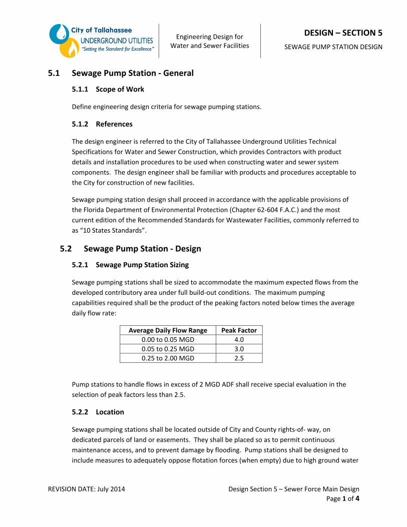
Sewage pumping stations shall be sized to accommodate the maximum expected flows from the
developed contributory area under full build‐out conditions. The maximum pumping
capabilities required shall be the product of the peaking factors noted below times the average
daily flow rate:
Average Daily Flow Range Peak Factor
0.00 to 0.05 MGD 4.0
0.05 to 0.25 MGD 3.0
0.25 to 2.00 MGD 2.5
Pump stations to handle flows in excess of 2 MGD ADF shall receive special evaluation in the
selection of peak factors less than 2.5.
5.2.2 Location
Sewage pumping stations shall be located outside of City and County rights‐of‐ way, on
dedicated parcels of land or easements. They shall be placed so as to permit continuous
maintenance access, and to prevent damage by flooding. Pump stations shall be designed to
include measures to adequately oppose flotation forces (when empty) due to high ground water
Engineering Design for Water and Sewer Facilities
DESIGN – SECTION 5
SEWAGE PUMP STATION DESIGN
REVISION DATE: July 2014 Design Section 5 – Sewer Force Main Design
Page 2 of 4
elevation. The electrical and mechanical equipment shall be protected from physical damage
for the 100‐year flood.
5.2.3 Type
Sewage pumping stations shall be of the submersible type. Water Resources Engineering
Division may consider deviations from the submersible type on a case‐by‐case basis.
5.2.4 Wet Well Design
The wet well shall be sized such that with any combination of inflow and pumping, the cycle of
operation for each pump will be not less than 5 minutes and the maximum retention time in the
wet well will not average more than 30 minutes.
All exposed surfaces of the wet well shall be lined with a protective coating in accordance with
the Technical Specifications. Liners shall be shown, labeled, and dimensioned on the Plans for
approval by the City.
Wet wells shall be vented to the atmosphere. The well shall be provided with an approved non‐
corrosive man way hatch which is capable of supporting expected loadings, and sized to allow
adequate space for equipment removal and replacement.
5.2.5 Pumping Systems
Pump systems shall have the minimum capability of pumping the peak design flow against the
maximum computed system total dynamic head (TDH).
A minimum of two pumps shall be provided. Where influent flows exceed 1 MGD, a minimum
of three pumps shall be provided. All pumps residing in a station shall be of the same
manufacture, electrical rating, inlet/outlet size, horsepower, and impeller size.
Pump intakes shall be capable of passing spheres of not less than 3‐inches in diameter.
Pump motors shall be non‐overloading, throughout the entire operating range of the pumps.
Thermal overloads shall be provided to shut off pump motor and initiate alarm for motor over
temperature condition.
Each pumping station control system shall include a liquid level controller, which shall sense the
sewage level in the wet well and provide appropriate signals to the logic circuits to produce the
required mode of operation for the pumping facilities. Capability shall be provided for manual
start‐stop control for all pumping units, as well as the normal automatic control from the liquid
level sensing and logic circuits. An automatic alternator shall change the starting sequence on
each pump cycle. A high and low water level alarm system shall be provided.
Engineering Design for Water and Sewer Facilities
DESIGN – SECTION 5
SEWAGE PUMP STATION DESIGN
REVISION DATE: July 2014 Design Section 5 – Sewer Force Main Design
Page 3 of 4
Each sewage pump shall be provided with an elapsed time meter to indicate pump‐running
times. Exterior station controls shall be housed within a panel, either pole mounted, or with a
freestanding enclosure. At minimum, the panel will be stainless steel of NEMA 3R weather tight
construction, with hasp and padlock. Electrical materials and methods shall comply with
National Electrical Code requirements.
A common provider shall furnish all pumps and corresponding electrical control system. The
provider’s representative shall conduct system start‐up services to be performed in the
presence of the inspector.
Pump stations of 0.5 MGD or more will be provided with flow recording meters.
System curve and pump performance curves shall be included in construction drawing.
5.2.6 Valves
Both isolation valves and check valves shall be placed on the discharge line of each pump to
afford pump isolation and bypassing. The check valves shall be located between the isolation
valves and the pump. Check valves shall be suitable for the material being handled. An isolation
valve shall also be provided on the common force main in the pump station.
5.2.7 Emergency Equipment
Emergency pumping capabilities shall be provided for all pump stations. Pumping capacity shall
be provided as follows:
1. Pump stations that receive flow from one or more pump stations through a force main
or pump stations discharging through pipes 12 inches or larger shall provide for
uninterrupted pumping capabilities, including an in‐place emergency generator.
2. For pump stations not addressed in “1” above, emergency pumping capability may be
accomplished by providing a connection for portable generating equipment.
3. Regardless of the type of emergency standby system provided, a riser from the force
main with rapid connection capabilities and appropriate valves shall be provided for all
pump stations to hook up portable pumps. All pump station reliability design features
shall be compatible with the available temporary service power generating and pumping
equipment of the authority responsible for operation and maintenance of the
collection/transmission system.
Engineering Design for Water and Sewer Facilities
DESIGN – SECTION 5
SEWAGE PUMP STATION DESIGN
REVISION DATE: July 2014 Design Section 5 – Sewer Force Main Design
Page 4 of 4
5.2.8 Miscellaneous
1. Pumping stations shall be enclosed with a fence or otherwise designed with appropriate
features that discourage the entry of animals and unauthorized persons. An
unobstructed sign made of durable weather resistant material shall be posted at a
location visible to the public with a telephone number for a point of contact in case of
emergency.
2. Pumping stations shall be protected from lightning and transient voltage surges. As a
minimum, stations shall be equipped with lightning arrestors, surge capacitors or other
similar protection devices, and phase protection.
3. Pumping stations shall be designed and located on the site so as to minimize adverse
effects resulting from odors, noise, and lighting.
END OF DESIGN SECTION 5
Engineering Design for Water and Sewer Facilities
DESIGN – SECTION 6
RECLAMINED WATER SYSTEM DESIGN
REVISION DATE: July 2014 Design Section 6 – Reclaimed Water System Design
Page 1 of 3
6.1 Reclaimed Water System ‐ General
6.1.1 Scope of Work
Define engineering design criteria for reclaimed water system design.
6.1.2 References
The design engineer is referred to the City of Tallahassee Underground Utilities Technical
Specifications for Water and Sewer Construction, which provides Contractors with product
details and installation procedures to be used when constructing water and sewer system
components. The design engineer shall be familiar with products and procedures acceptable to
the City for construction of new facilities.
Reclaimed water system design shall proceed in accordance with the applicable provisions of
the Florida Department of Environmental Protection (Chapter 62‐610, F.A.C.; Chapter 62‐555
F.A.C.) and the most current edition of the U.S. EPA Guidelines for Water Reuse
(EPA/625/R04/108, at time of printing).
6.2 Reclaimed Water System ‐ Design
6.2.1 Reclaimed Water System Sizing
Size the reclaimed water distribution systems in accordance with the approved master plan
established for that area. In the absence of an approved master plan, size the reclaimed water
distribution system to deliver the design demand while maintaining a minimum residual system
pressure greater than 20 PSI at all points in the system for the full build‐out conditions.
The target maximum reclaimed water system head loss is 1 foot of head loss per 1,000 feet of
pipe under average day demand conditions, using a Hazen‐William friction factor (C‐factor) of
120 for design purposes. The target maximum fluid velocity range is 5‐8 FPS under maximum
day demand conditions.
Make design computations using hydraulic modeling software, such as Innovyze InfoWater,
Bentley WaterCAD, or EPANet. Submit calculations/modeling results to the City of Tallahassee
Underground Utilities Development Review Coordinator for review.
6.2.2 Placement of Reclaimed Water System Piping and Appurtenances
6.2.2.1 Piping
Install reclaimed water system piping for new development in accordance with the
Tallahassee Area Utilities Coordinating Committee – Recommended Guide for Utility
Engineering Design for Water and Sewer Facilities
DESIGN – SECTION 6
RECLAMINED WATER SYSTEM DESIGN
REVISION DATE: July 2014 Design Section 6 – Reclaimed Water System Design
Page 2 of 3
Placement, as provided in the Appendix A, whenever possible. Exceptions from this
guide must be approved by the City and/or County, when applicable.
Loop the reclaimed water distribution system piping, whenever possible. Avoid dead‐
end mains, except when the design engineer can demonstrate that looping is not
possible. When required, such as in a cul‐de‐sac, dead‐end mains must have a flush
stand located at the end of the main for flushing.
6.2.2.2 Valves
Provide valves to isolate reclaimed water system piping for repair and maintenance.
The number of valves provided depends on the configuration of the distribution
network. Ideally, each pipe should have at least one valve. For more critical pipes, such
as those with large number of customer or substantial demand requirements, multiple
valves may be warranted.
As a general rule, use the “N‐1” valve place scheme at junctions, where “N” is the
number of pipes at a junction (tees and crosses). For example, a tee has three pipes
connecting at the junction; therefore, two valves should be installed (3 ‐ 1=2).
Place valves on at both ends of all jack and bore crossings; and at both ends of crossings
of those streets classified as major collectors, arterial roads, or with 3 or more thru
lanes of traffic.
Place valves on straight runs of pipe (no branches) at intervals no greater than 500 feet
for pipe sections with customer services, or at intervals of 1,000 feet for pipe section
without customer services.
6.2.3 Thrust Restraint
Pressure piping fittings require that adequate means of restraining unbalanced thrust forces is
provided in accordance with AWWA Manual M23 and the recommendations of the
manufacturer. Thrust restraint may be provided by mechanical devices or cast‐in‐place concrete
blocking (if approved by the City). Mechanical thrust‐restraint devices must be pressure‐rated
by their manufacturers and must not exert forces that will cause failure when assembled on the
pipe or fitting.
The minimum number of restrained joints required for resisting thrust forces shall be
determined by the pipe size, material, type of valve or fitting, operating conditions, pipe trench,
and soil type. Minimum restrained lengths for many typical applications are provided in the
Standard Construction Details, which have been calculated for various pipe material and fittings
based on the following minimum design parameters:
Engineering Design for Water and Sewer Facilities
DESIGN – SECTION 6
RECLAMINED WATER SYSTEM DESIGN
REVISION DATE: July 2014 Design Section 6 – Reclaimed Water System Design
Page 3 of 3
Unified Soil Classification: SM Soil Type Safety Factor: 1.5 Trench Type: Type 3
Depth of Bury: 3 Feet Test Pressure: 150 PSI
The Engineer of Record will verify the above design parameters are suitable for the proposed
installation. Any reductions in minimum restrained lengths provided in the Standard
Construction Details and the design parameters above shall be requested in writing by an active
Florida Licensed Professional Engineer, in good standing with Florida Board of Professional
Engineers. Such requests shall include suggested changes to design parameters, supporting
documentation, and new restrained length calculations, signed and sealed by the Professional
Engineer.
END OF DESIGN SECTION 6
AppendixARecommendedGuideforUtilityPlacement
Preparedby:
WaterResourcesEngineeringDivision408NorthAdamsStreetTallahassee,Florida32301
July2014

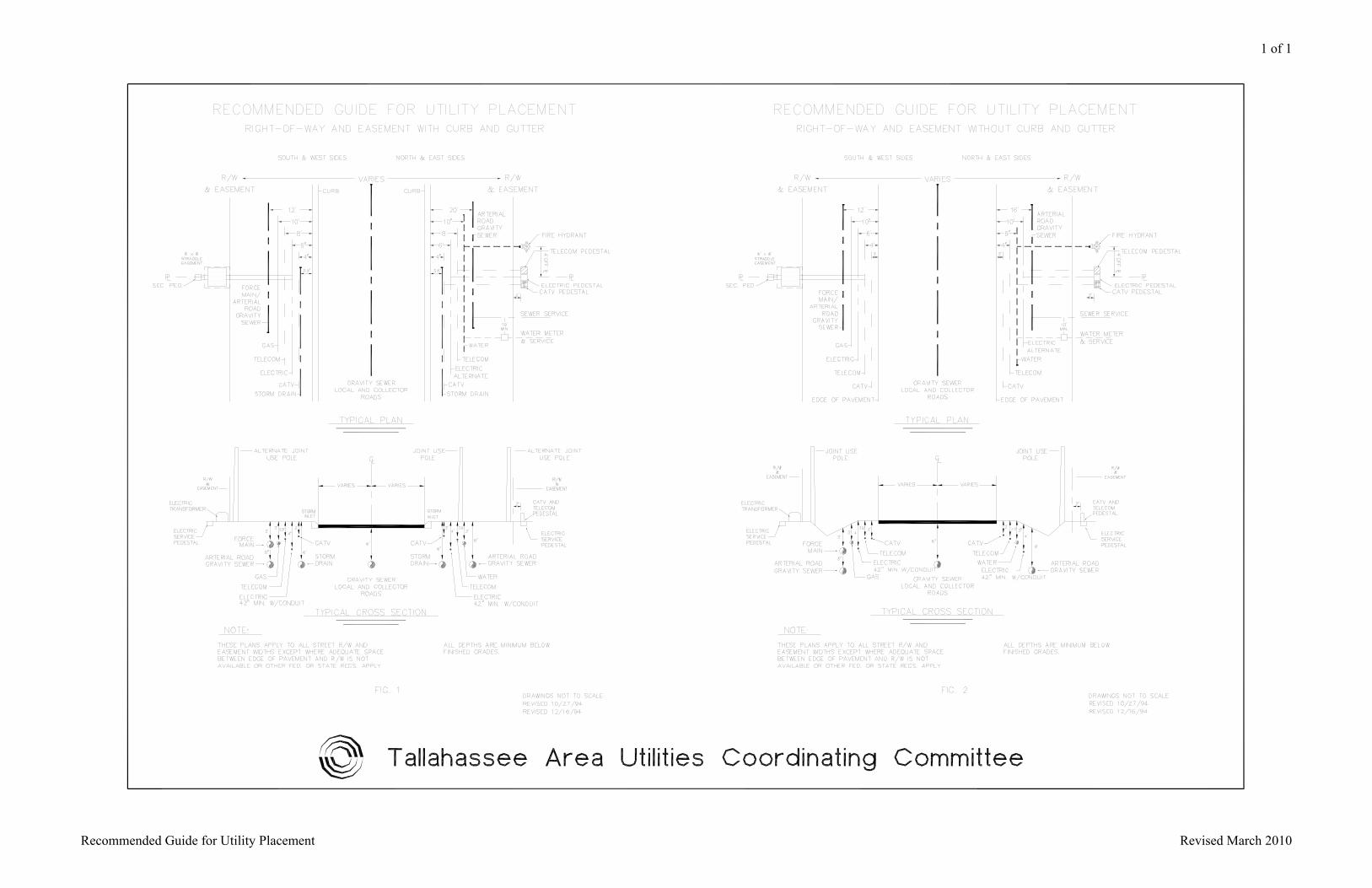
1 of 1
Recommended Guide for Utility Placement Revised March 2010

(THIS PAGE LEFT INTENTIONALLY BLANK)
AppendixBPotableWaterDemandCalculationRates
Preparedby:
WaterResourcesEngineeringDivision
408NorthAdamsStreetTallahassee,Florida32301
July2014

REVISION DATE: July 2014 Appendix B – Potable Water Demand Calculation Rates
Page 1 of 3
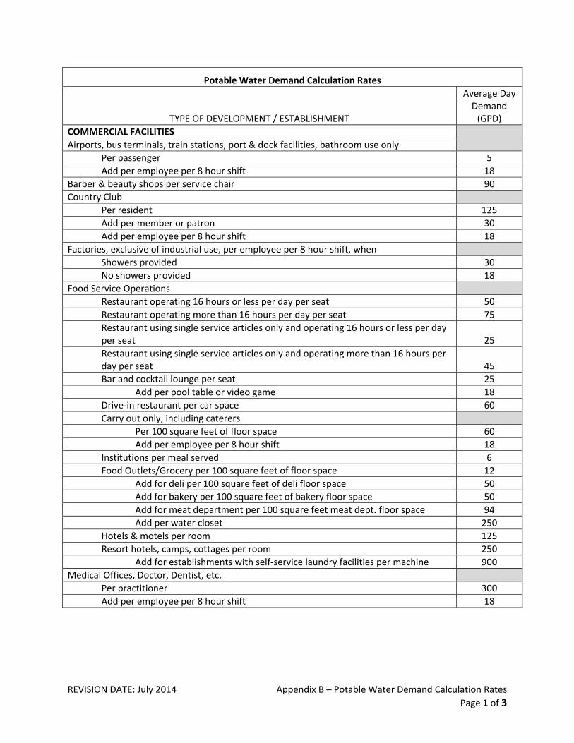
Potable Water Demand Calculation Rates
TYPE OF DEVELOPMENT / ESTABLISHMENT
Average Day Demand (GPD)
COMMERCIAL FACILITIES
Airports, bus terminals, train stations, port & dock facilities, bathroom use only
Per passenger 5
Add per employee per 8 hour shift 18
Barber & beauty shops per service chair 90
Country Club
Per resident 125
Add per member or patron 30
Add per employee per 8 hour shift 18
Factories, exclusive of industrial use, per employee per 8 hour shift, when
Showers provided 30
No showers provided 18
Food Service Operations
Restaurant operating 16 hours or less per day per seat 50
Restaurant operating more than 16 hours per day per seat 75
Restaurant using single service articles only and operating 16 hours or less per day per seat 25
Restaurant using single service articles only and operating more than 16 hours per day per seat 45
Bar and cocktail lounge per seat 25
Add per pool table or video game 18
Drive‐in restaurant per car space 60
Carry out only, including caterers
Per 100 square feet of floor space 60
Add per employee per 8 hour shift 18
Institutions per meal served 6
Food Outlets/Grocery per 100 square feet of floor space 12
Add for deli per 100 square feet of deli floor space 50
Add for bakery per 100 square feet of bakery floor space 50
Add for meat department per 100 square feet meat dept. floor space 94
Add per water closet 250
Hotels & motels per room 125
Resort hotels, camps, cottages per room 250
Add for establishments with self‐service laundry facilities per machine 900
Medical Offices, Doctor, Dentist, etc.
Per practitioner 300
Add per employee per 8 hour shift 18

REVISION DATE: July 2014 Appendix B – Potable Water Demand Calculation Rates
Page 2 of 3
Potable Water Demand Calculation Rates
TYPE OF DEVELOPMENT / ESTABLISHMENT
Average Day Demand (GPD)
COMMERCIAL FACILITIES (CONTINUED)
Office building per 100 square feet or per employee per 8 hour shift, whichever is greater 18
Transient Recreational Vehicle Park per overnight RV space
Without water and sewer hookup per vehicle space 60
With water and sewer hookup per vehicle space 90
Service stations per water closet
Open 16 hours per day or less 300
Open more than 16 hours per day 400
Retail shopping centers, without food or laundry, per square foot of floor space 0.125
Sports stadiums, ball parks, race track per seat 5
Stores per bathroom 125
Swimming and bathing facilities (public) per person 12
Theatres and Auditoriums per seat 5
Veterinary Clinic
Per practitioner 300
Add per employee per 8 hour shift 18
Add per kennel, stall or cage 25
Warehouse
Add per employee per 8 hour shift 18
Add per loading bay 125
Self‐storage, per unit (up to 200 units) 1
INSTITUTIONAL FACILITIES
Churches, including kitchen flows
Per seat, if meals are not served on a regular basis 4
Add per meal prepared if meals are prepared on a routine basis 6
Hospitals
Per bed, not including kitchen flows 250
Add per meal prepared 6
Nursing homes, adult congregate facilities
Per bed, not including kitchen flows 125
Add per meal prepared 6
Parks, public picnic
With toilets only, per person 5
With bathhouse, showers & toilets, per person 12
Public institutions other than schools and hospitals
Per person 125
Add per meal prepared 6
REVISION DATE: July 2014 Appendix B – Potable Water Demand Calculation Rates
Page 3 of 3
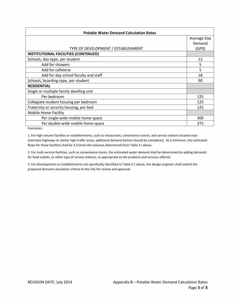
Potable Water Demand Calculation Rates
TYPE OF DEVELOPMENT / ESTABLISHMENT
Average Day Demand (GPD)
INSTITUTIONAL FACILITIES (CONTINUED)
Schools, day‐type, per student 12
Add for showers 5
Add for cafeteria 5
Add for day school faculty and staff 18
Schools, boarding‐type, per student 90
RESIDENTIAL
Single or multiple‐family dwelling unit
Per bedroom 125
Collegiate student housing per bedroom 125
Fraternity or sorority housing, per bed 125
Mobile Home Facility
Per single‐wide mobile home space 300
Per double‐wide mobile home space 375 Footnotes:
1. For high volume facilities or establishments, such as restaurants, convenience stores, and service stations located near
interstate highways or similar high‐traffic areas, additional demand factors should be considered. At a minimum, the estimated
flows for these facilities shall be 3.0 times the volumes determined from Table 2.I above.
2. For multi‐service facilities, such as convenience stores, the estimated water demand shall be determined by adding demands
for food outlets, or other type of service stations, as appropriate to the products and services offered.
3. For developments or establishments not specifically identified in Table 2.1 above, the design engineer shall submit the
proposed demand calculation criteria to the City for review and approval.

(THISPAGELEFTINTENTIONALLYBLANK)


Engineering Design for Water and Sewer Construction July 2014
City of Tallahassee Underground Utilities ‐ Water Resources Engineering Division 408 North Adams Street, 3rd Floor, Tallahassee, Florida 32301