2007 - buques
12
Revista Ciencia & Tecnología de Buques Date < 19/Oct/2007>. City: <São Paulo - Brazil> Page 1 of 12 A diagnostic of Diesel-Electric propulsion for ships Newton Narciso Pereira University of São Paulo, Department of architecture naval and oceanic engineering Professor Mello Moraes Street, 223, A13 Room, University City São Paulo / São Paulo / Brazil Tel: (011) 3091-5350 Extension 220 Fax: (011) 3091-5350 Extension 200 e-mail: [email protected] – [email protected] ABSTRACT The main objective of this paper is to present an analysis about Diesel-Electric Propulsion System used in naval, maritime and fluvial ships. There are many advantages and some disadvantages of this system; besides there have been developed new propulsion systems to aid in the maneuver and steering of ships. Recently electric ship have employed an very interesting architecture arrangements’ and these technologies permit to achieve a reduction of operational cost, weight and more efficiency. Considerations for propulsion systems utilizing the various types of machine technologies like for example the Azipod system are also discussed. Key Words: Diesel-Electric Propulsion system, Azipod propulsion, maneuver, steering Introduction Recently, several ships have employed electric propulsion systems motivated by factors connected with gain in maneuver and steering and reduction of fuel consume and environmental impact. Other factors are related with new options of machine arrangement, better control and more torque capacity and a softer transmission. The use of Diesel-Electric propulsion (DE) is not recent. The first electric propeller systems appeared in the end of XIX century in Russia. This ship was used in the passenger transport and it was powered with a small block of batteries (Arpiainen et al., 1993). The same propulsion system was installed in the “Neptune Ship” in 1913 (SOLER & MIRANDA, 1997). In the century ago electric systems were applied in naval, merchant maritime and fluvial ships and along the XX century that systems have been improved due to technological advances. In this period, a mile-stone in the development of electric ships took place in 1911-1913, when American Navy installed a 5500 HP in the Collier Jupiter. This ship operated successfully over a 30 year period, which was terminated by warfare activity in 1943 after serving as the US Navy’s first aircraft carrier Langley. In the fluvial navigation that application was widely disseminated in the United States, when the American Navy built your first “lightships” with Diesel-Electric propulsion system to operate in the American waterways from 1913 to 1938. In the fluvial environment, Luna was the first Diesel-Electric fluvial tugboat merchant built in 1932 in the EUA. That represented a big step to electrics system evolution, because this propulsion system had a General Electric main motor with 516 HP (411 kW) of small weight, that offered a good space intern distribution. Besides, this system allowed an optimization of propeller speed by using an instantaneous speed controller to change the motor speed in eight ranges of different speeds of ship (LUNA PRESERVATION SOCIETY, 2006). In 1936, in England was built a big fluvial tugboat Diesel- Electric called Sir Montagu’. It shipped in the Thames River and had a displacement of 61 ton and an installed power of 440 HP (323 kW). With system evolution, in 1976 in Russia was used CA-CC system in the icebreaker Kaptan Ismaylov class with 2.5 MW power installed, where it already uses electronics device to control motor speed. In 1986, propulsion systems CA-CA were introduced in the icebreaker Otso class. This vessel had a plant projected for use of thyristors control. In this year a project group of Asea Brown Boveri - ABB from Norway utilized for the first time the inverter Pulse Width Modulation- PWM, in the propulsion installation of “Lorelay” ship. In 1990, the ABB developed a system called Azipod which consists of an electric engine, lodged inside of an adjusted pod to supply better draining of the fluid, hardwired to a
-
Upload
newton-narciso-pereira -
Category
Documents
-
view
56 -
download
1
Transcript of 2007 - buques
Revista Ciencia & Tecnología de Buques
Date < 19/Oct/2007>. City: <São Paulo - Brazil> Page 1 of 12
A diagnostic of Diesel-Electric propulsion for ships
Newton Narciso Pereira University of São Paulo, Department of architecture naval and oceanic engineering
Professor Mello Moraes Street, 223, A13 Room, University City São Paulo / São Paulo / Brazil
Tel: (011) 3091-5350 Extension 220 Fax: (011) 3091-5350 Extension 200
e-mail: [email protected] – [email protected]
ABSTRACT The main objective of this paper is to present an analysis about Diesel-Electric Propulsion System used in naval, maritime and fluvial ships. There are many advantages and some disadvantages of this system; besides there have been developed new propulsion systems to aid in the maneuver and steering of ships. Recently electric ship have employed an very interesting architecture arrangements’ and these technologies permit to achieve a reduction of operational cost, weight and more efficiency. Considerations for propulsion systems utilizing the various types of machine technologies like for example the Azipod system are also discussed. Key Words: Diesel-Electric Propulsion system, Azipod propulsion, maneuver, steering
Introduction
Recently, several ships have employed electric propulsion systems motivated by factors connected with gain in maneuver and steering and reduction of fuel consume and environmental impact. Other factors are related with new options of machine arrangement, better control and more torque capacity and a softer transmission. The use of Diesel-Electric propulsion (DE) is not recent. The first electric propeller systems appeared in the end of XIX century in Russia. This ship was used in the passenger transport and it was powered with a small block of batteries (Arpiainen et al., 1993).
The same propulsion system was installed in the “Neptune Ship” in 1913 (SOLER & MIRANDA, 1997). In the century ago electric systems were applied in naval, merchant maritime and fluvial ships and along the XX century that systems have been improved due to technological advances. In this period, a mile-stone in the development of electric ships took place in 1911-1913, when American Navy installed a 5500 HP in the Collier Jupiter. This ship operated successfully over a 30 year period, which was terminated by warfare activity in 1943 after serving as the US Navy’s first aircraft carrier Langley. In the fluvial navigation that application was widely disseminated in the United States, when the American Navy built your first “lightships” with Diesel-Electric propulsion system to operate in the American waterways from 1913 to 1938.
In the fluvial environment, Luna was the first Diesel-Electric fluvial tugboat merchant built in 1932 in the EUA. That represented a big step to electrics system evolution, because this propulsion system had a General Electric main motor with 516 HP (411 kW) of small weight, that offered a good space intern distribution. Besides, this system allowed an optimization of propeller speed by using an instantaneous speed controller to change the motor speed in eight ranges of different speeds of ship (LUNA PRESERVATION SOCIETY, 2006). In 1936, in England was built a big fluvial tugboat Diesel-Electric called Sir Montagu’. It shipped in the Thames River and had a displacement of 61 ton and an installed power of 440 HP (323 kW). With system evolution, in 1976 in Russia was used CA-CC system in the icebreaker Kaptan Ismaylov class with 2.5 MW power installed, where it already uses electronics device to control motor speed. In 1986, propulsion systems CA-CA were introduced in the icebreaker Otso class. This vessel had a plant projected for use of thyristors control. In this year a project group of Asea Brown Boveri - ABB from Norway utilized for the first time the inverter Pulse Width Modulation- PWM, in the propulsion installation of “Lorelay” ship. In 1990, the ABB developed a system called Azipod which consists of an electric engine, lodged inside of an adjusted pod to supply better draining of the fluid, hardwired to a

Revista Ciencia & Tecnología de Buques
Date < 19/Oct/2007>. City: <São Paulo - Brazil> Page 2 of 12
propeller. This set is installed in the external side of the hull and has the capacity to turn 360 degrees around its proper axle and can provide the required thrust in any direction. Appear in 1996, a new Diesel-electric propulsion system developed by Volvo Penta adapted to fluvial ships to container transport in the Sweden waterways. This system was expanded in 1999 and implemented the concept Ecoship, ecologic ship. The Inbiship, a company of same group, annunciated they had developed a new propulsion system in pod adapted to fluvial ships (INBISHIP, 2006). The shipbuilder Bijlsma Shipyard announced recently, in 2004, the launched of a small LNG ship with 1100 m3 capacity to operate in Norway coast with mix propulsion electric system. Every main machines is connected with generators to supply 2 electric motors of 900 kW each, with frequency controlled, join azimuth propellers (HANSEN & LYESBO, 2004). In 2004, the Schiffbau und Entwicklungsgesellschaft Tangermünde- SET build a patrol ship for a Germany Navy to operate in inland waters using Diesel-Electric propulsion system. This ship was equipped with 2 electric motors of 370 kW and an azimuth system, during the operation it achieve 12 knots of speed (SHIP AND BOAT INTERNATIONAL, 2003). Nowadays, in France the Airbus Company uses a fluvial ship with Diesel-Electric propulsion to transport of fuselage plan unto long Garonne River. This ship have 2 electric motors of 735 kW and a bow thruster de 400 kW (VACON, 2006). Finally, in relation to new developments about electric propulsion installations, the Creating Inland Navigation (2006) presents a study about fuel cells to action electric motors installed in fluvial ships in Europe. The basic idea is change Diesel-Generators by fuel cells to provide energy to electric motors. Besides, environmental it is very important environmentally because it can provide a big reduction in gases emissions and noise is insignificant. However, in the present the big problem of this application is the high cost and low autonomy of power during a trip. So, this paper follows a discussion about use of Diesel-Electric propulsion systems presenting the current state of the art and some of more noteworthy future electric ships and technology options as well as their advantages and disadvantages. Additionally, it is present cases of this application in three segments of ships like naval, maritime and fluvial. Diesel-Electric Propulsion Characteristics
This system consisting of an electric generator, or alternator, set in motion for an engine is understood for Diesel-electric propulsion, who supplies energy for an electric engine, which sets in motion the propeller. The main characteristic of the Diesel-electric system is the control of the speed of the ship by the regulation of the rotation of the electric engines. Usually, the electric engines used possess a great number of pole regions and can be connected directly, or by means of a gear reducing, to the propeller. The capacity and the characteristics of the equipment are those defining by designers, and the modularity of the system allows that, in high speed, all the engines are used, and in economic speeds the unnecessary engines are disconnected (PEREIRA & BRINATI, 2007). Concerning to the propeller element, it can be used as controllable-pitch and fixed-pitch propeller. However, the former is more used, because the use of the electric engine allows rotation control of the propeller for some bands of operation. Basically, a propulsion plant DE is composed for the set Diesel-generator (DG), frequency converters, electric engines, axles and propellers, and gear reducing when necessary. McCoy (2003) affirms that traditional electric ship propulsion system is compared with a mechanical drive system in relation the effectiveness. The electric propulsion system is essentially a transmission for changing the relatively high speed and low torque of the prime mover to the extremely low speed and high torque required to turn the propellers. Harrington (1970) explains that block Generator – Electric Machine like an electric transmission. Other important aspect is that electric propulsion system must also provide for speed change and reversal of the propeller. A great innovation in the last years is a Full Electric Propulsion and All Electric Ship where it is allowed the total integration of consumption of ship energy. McCoy (2003) describes in this context that there are two fundamental changes in the way electric drive ships are designed which account for their resurgence. First, there are the developments of high power, devices switching and multi-megawatt variable speed drives. The second is the shift to an integrated architecture following in Figure 1. This system has become common in ships like tanker, ferries, icebreaker and military. It is very similar with the Diesel-Electric propulsion, with a difference in the concept of rational energy use in the ship. All energy generated in the ship is
Revista Ciencia & Tecnología de Buques
Date < 19/Oct/2007>. City: <São Paulo - Brazil> Page 3 of 12
used in action electric motor and condition of service ship “hotel load”.
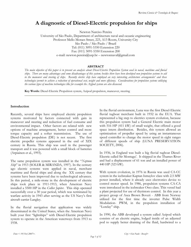
Figure 1 - Integral Electric drive ship
McCoy (2003) is emphatic in the affirmation that combining the propulsion and ship service electrical systems not only makes the ship more flexible like an integrated electric architecture, but also eliminates the need for shafts between the propeller and the main motors, allowing the ship designer virtually unlimited flexibility in arranging the ship. Evaluation of this propulsion system a) Advantages of Diesel-Electric In this section are presented the advantages of Diesel-Electric propulsion in relation of conventional application. The main advantage of the Diesel-electric propulsion is the speed adjustment of the propeller independently of the rotation of the main machine (machine that generates energy mechanics). The adjustment of the rotation of the propeller is determined by the speed of the electric engine; thus, the main machine works in a constant-speed setting in motion a generator that supplies energy the electric engine. The speed control of the electric engine can be realized through the frequency invert (CA) or voltage control (CC) applied to the engine. Arpiainen et al. (1993) present the benefits of the work of this system in icebreaker ships. The main advantages of this system are: bigger torque in low speeds and systems of softer transmission. Soler & Miranda (1997) present as advantage related to the electric propulsion the minimization in maintenance and operational costs and fuel consumption. An important affirmation is that electric engines show little cost of maintenance and repair in relation with mechanic engines. In this context, Simpson (1997) makes an affirmation, when a ship uses Diesel-Electric propulsion in 30 years the
maintenance cost trend is little in comparison with Diesel mechanic ships. Like in traditional ships, the speed motor define the speed of propeller, in same conditions, the ship can not operate in maximum output, in this cases, the fuel consume is high, but with electric engines this not occur. In relation with technique aspect, Soler & Miranda (1997), McCOY (2003), Mezger (1997) affirm that the electric propulsion offer advantages in terms of maneuverability, automatics controls, more capacity of reversion engines without the need of special agents and dispense gear box, little gear box noise and vibration in the propeller axle. In the question of the maneuverability, Hansen & Lyesbo (2004) explain that the propulsion DE provides advantages for the ship, mainly in the maneuvers of crash stop. This occurs for the fact that the electric engine provides a better control of the rotation of the propeller and to quickly change the direction of the rotation of this, which reduces the distance and the time of stop. Ships with conventional propulsion can wait until 30 seconds to stop motor and start the reversion in other direction. For example, we can speak about trimaran RV Triton ship of English Navy with Diesel-Electric propulsion, when it operate in the maximum service speed of 22 knots, when in crash stop that need of 5 times your length to stop, but with propulsion Diesel that distance is 10 times more (FKI INDUSTRIAL DRIVES, 2002). In recent studies with bigger Diesel-Electric ships that have demonstrated a reduction from 30% to 50% in the crash stop in relation conventional propulsion. In general, a ship with this type of propulsion system has a radius turn 40% smaller than a ship with conventional propulsion. The Canadian Navy has ships with Diesel-Electric propulsion systems and the tactic diameter is 2,8 time their length, smaller than the recommendation that this parameter don’t pass 5 times the length ship (IRVING SHIPBUILDING INC., 2006). In relation to the environmental questions, Wilgenhof & Stapersma (1997) and the Department of Electrical Engineering United Naval States Academy (2006) have analyzed the impact of the Diesel-electric propulsion in the environment. They affirm that the propulsion DE reduces the emission rates of pollutant gases around 10% to 20%, in relation to the propulsion conventional Diesel. Ellingsen et al. (2002) developed a model to calculate the environmental impact during the operations of ships comparing the gases emissions about several kinds of propulsion installations, like Diesel mechanic and Diesel-Electric. In case of fishing ships, authors make an evaluation of same aspects: acid rain, water eutrophization,
Revista Ciencia & Tecnología de Buques
Date < 19/Oct/2007>. City: <São Paulo - Brazil> Page 4 of 12
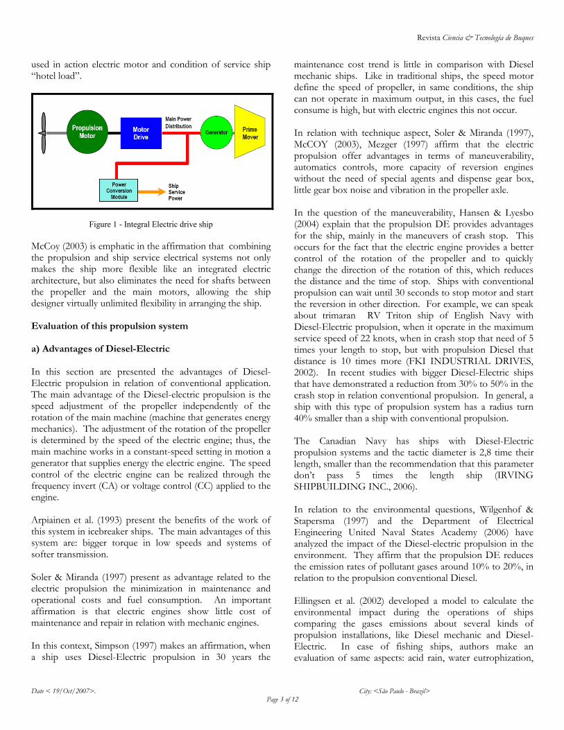
green house, carcinogens gases, heavy metal and smog. Figure 2, shows the result of environmental impact considering the total power ship in function of amount (kg) fished.
Figure 2 - Comparison of emissions ship
Clearly the exam of Figure 2 appoints that Diesel-electric propulsion produce fewer gases than conventional Diesel system. An important fact is that this model also considerate the emission in port operation and in stop time of ship. Observe that the contribution to greenhouse is similar in both cases, where the carbon dioxide emitted during Diesel burn is the factor that contributes for greenhouse, however, for other pollutant elements the Diesel-Electric present more environmental advantages. Restriction and Disadvantages However, there are innumerous advantages of electric systems, Blokland & Ebling (1995) e Guimarães (1999) call attention for a human safety in the use of electric devices. It is necessary that every person involved in the operation and maintenance of devices are consciences and prepared for risks of these systems. Guimarães (1999) identify five factors that explain the main causes of accidents: omission, wrong action, intemperate action, not control and wrong control. So, it is important that the crew be prepared to work with accidents that can occur. Note that it is not only about installing more modern propulsion systems in fluvial ships, but also it is necessary to train and prepare the crew with new technologies. Morishita (1985) explains that human operator is not preparing to management complex systems, that can become inefficient their operation, then it is very danger. Because of this, it is necessary the consciences of problem because electric systems have high voltage and produce disastrous consequences.
The crew must be prepared to management fails in the systems, because it can endanger the steering of ship. Borman & Sharman (1995) and Koskela et al. (1995) explain that electric ships must attend the established norms by classification societies in relation with the system failure. Then, it is recommendable pay attention to:
Isolation systems of devices in case of curt-circuits;
Proceed to eliminate fails to reduces accidents risk and avoid fires;
Separate the power supply of electric engines in two compartments;
Total separation of vitals devices to ship operation in case of fire or flooding compartment.
In the bibliographies analyzed , it could be verify that few authors speak about technical disadvantages of this kind of propulsion system, only detaching positive points. However, Soler & Miranda (1997) make the following observations about the disadvantages of system like: more acquisition cost of devices in relation Diesel conventional system, and more weight in relation Diesel motor. Without trying to set a discussion about advantages and disadvantages presented for these authors, in general there have been verified a crescent numbers of ships using Diesel-Electric propulsion in every segments of naval industry. It appoints that despite its high acquisition cost, in the long term the benefits gained can guarantee their viability. In Brazil, for example, economical and cultural aspects of fluvial ship-owner trend have been a problem for the diffusion of these systems. So, a detailed evaluation must be realized to verify economical, technical and environmental improvements in electrical ships.
Special Diesel-Electric Pod propeller The first project of propeller pod was conceived in 1955, when Pleuger and Busmann projected the system and patented it in the United States (PÊGO et al., 2005). In 1990, the ABB launched in the market the same concept of propulsion improved for commercial applications called Azipod. Basically, the system consists of an electric engine, lodged inside of an adjusted pod to supply better draining of the fluid, hardwired to a propeller. This set is installed in the external side of the hull and has the capacity to turn 360 degrees around its proper axle and can pro-vide the required thrust in any direction. The first Azipod was installed on the waterway service vessel called Seili in 1990. Although exist other companies who manufacture propellers in pod, during the investigation was noticed that only the systems manufactured for the ABB would be of interest for
Environmental Impact
Revista Ciencia & Tecnología de Buques
Date < 19/Oct/2007>. City: <São Paulo - Brazil> Page 5 of 12
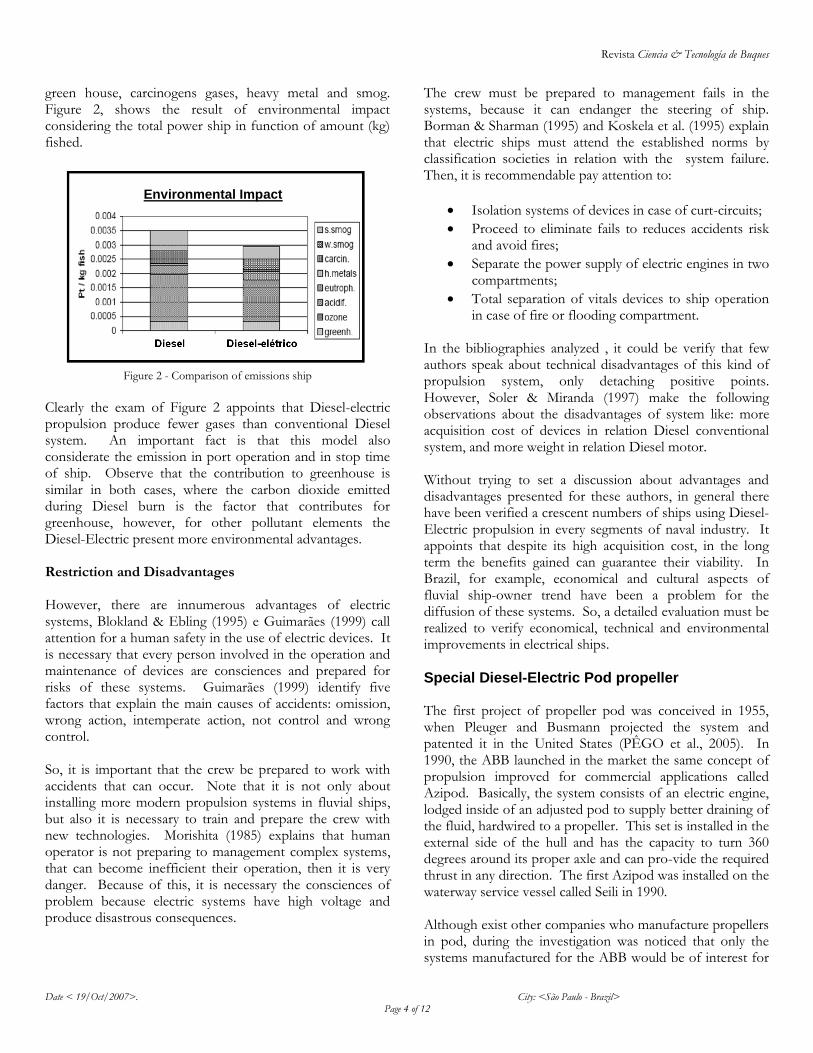
fluvial towboats given its configurations. In the case of Compact Azipod, that is constructed in 5 different bands of power, that vary between 0,4 MW up to 4,2 MW and are ideal for fluvial towboats. These systems can be observed in Figures 3 and 4.
Figure 3 – Azipod System
Figure 4 – Compact Azipod
The configuration of this propulsion system can be seen in the Figure 5.
Figure 5 – Azipod configuration
In relation to the advantages presented on the electric propulsion, the Azipod extends the range of benefits for this propulsion system. Laukia (1995) points out the following profits gotten with the Azipod system:
Reduction of the machinery space;
The system can be used in diverse types of ships;
Flexibility in general arrangement design;
The possibility of using a wider design engine market;
Excellent condition of maneuverability, even in low speeds, because the propellers can be directed for all the directions;
Reduction in the fuel consumption;
System with high level of reliability; it can be installed in the last period of the construction, some weeks before the launching;
Low speed operation with low propellers revolutions;
Excellent maneuverability, propeller thrust can be steered in any direction.
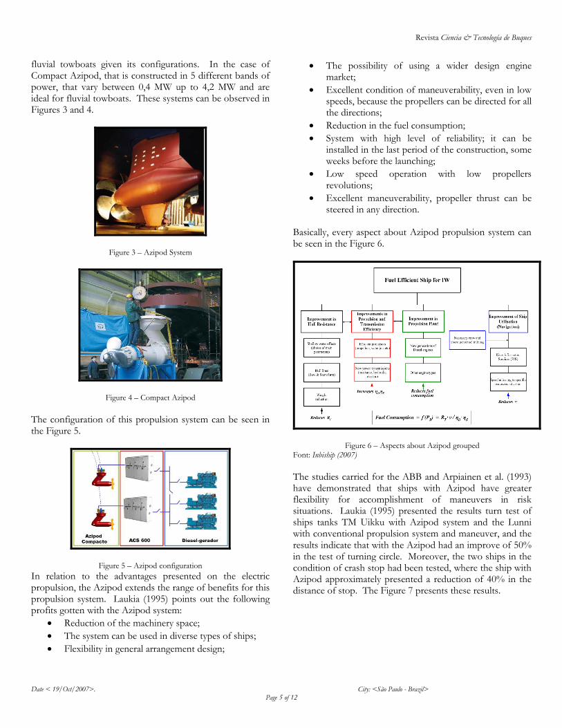
Basically, every aspect about Azipod propulsion system can be seen in the Figure 6.
Figure 6 – Aspects about Azipod grouped Font: Inbiship (2007)
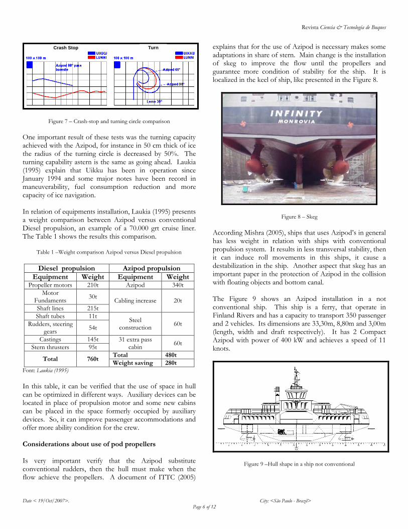
The studies carried for the ABB and Arpiainen et al. (1993) have demonstrated that ships with Azipod have greater flexibility for accomplishment of maneuvers in risk situations. Laukia (1995) presented the results turn test of ships tanks TM Uikku with Azipod system and the Lunni with conventional propulsion system and maneuver, and the results indicate that with the Azipod had an improve of 50% in the test of turning circle. Moreover, the two ships in the condition of crash stop had been tested, where the ship with Azipod approximately presented a reduction of 40% in the distance of stop. The Figure 7 presents these results.
Revista Ciencia & Tecnología de Buques
Date < 19/Oct/2007>. City: <São Paulo - Brazil> Page 6 of 12
Figure 7 – Crash-stop and turning circle comparison
One important result of these tests was the turning capacity achieved with the Azipod, for instance in 50 cm thick of ice the radius of the turning circle is decreased by 50%. The turning capability astern is the same as going ahead. Laukia (1995) explain that Uikku has been in operation since January 1994 and some major notes have been record in maneuverability, fuel consumption reduction and more capacity of ice navigation. In relation of equipments installation, Laukia (1995) presents a weight comparison between Azipod versus conventional Diesel propulsion, an example of a 70.000 grt cruise liner. The Table 1 shows the results this comparison.
Table 1 –Weight comparison Azipod versus Diesel propulsion
Diesel propulsion Azipod propulsion
Equipment Weight Equipment Weight Propeller motors 210t Azipod 340t
Motor Fundaments
30t Cabling increase 20t
Shaft lines 215t
Shaft tubes 11t Steel
construction 60t Rudders, steering
gears 54t
Castings 145t 31 extra pass cabin
60t Stern thrusters 95t
Total 760t Total 480t
Weight saving 280t Font: Laukia (1995)
In this table, it can be verified that the use of space in hull can be optimized in different ways. Auxiliary devices can be located in place of propulsion motor and some new cabins can be placed in the space formerly occupied by auxiliary devices. So, it can improve passenger accommodations and offer more ability condition for the crew. Considerations about use of pod propellers Is very important verify that the Azipod substitute conventional rudders, then the hull must make when the flow achieve the propellers. A document of ITTC (2005)
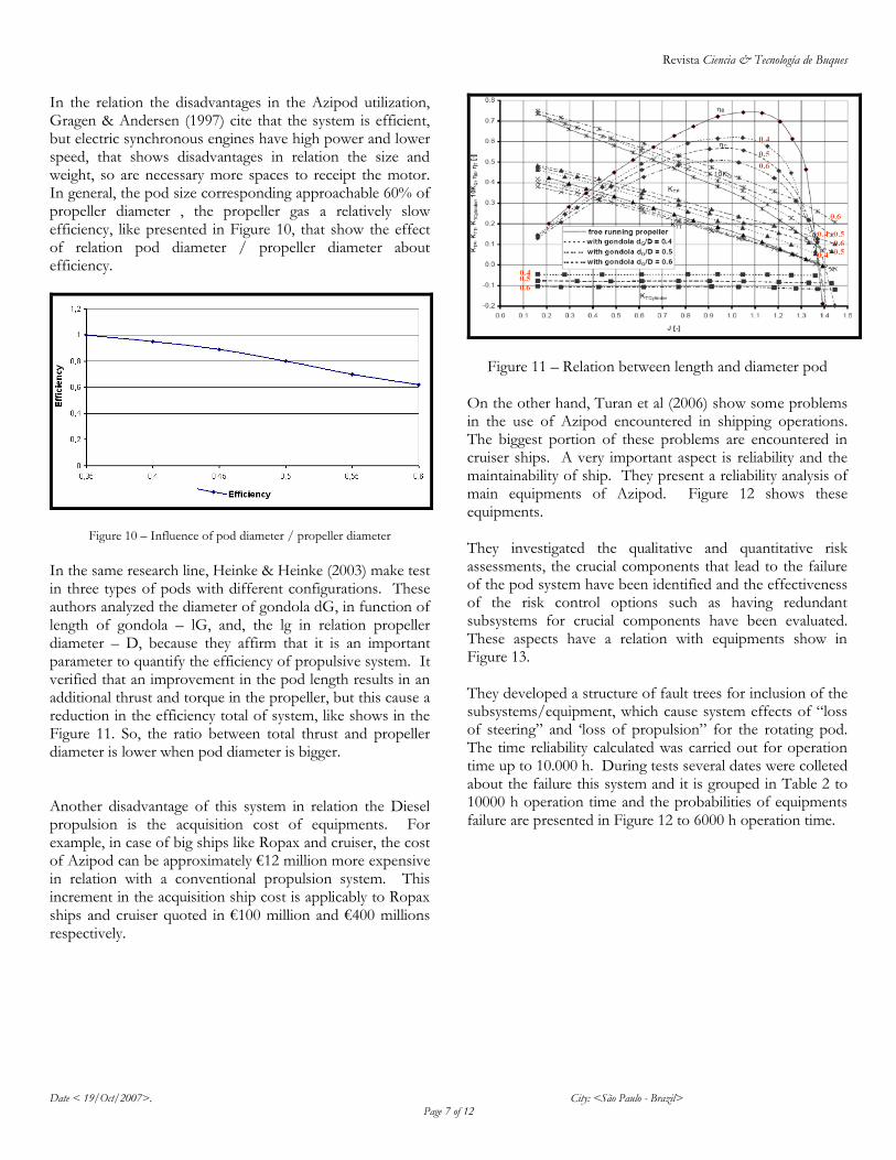
explains that for the use of Azipod is necessary makes some adaptations in share of stern. Main change is the installation of skeg to improve the flow until the propellers and guarantee more condition of stability for the ship. It is localized in the keel of ship, like presented in the Figure 8.
Figure 8 – Skeg
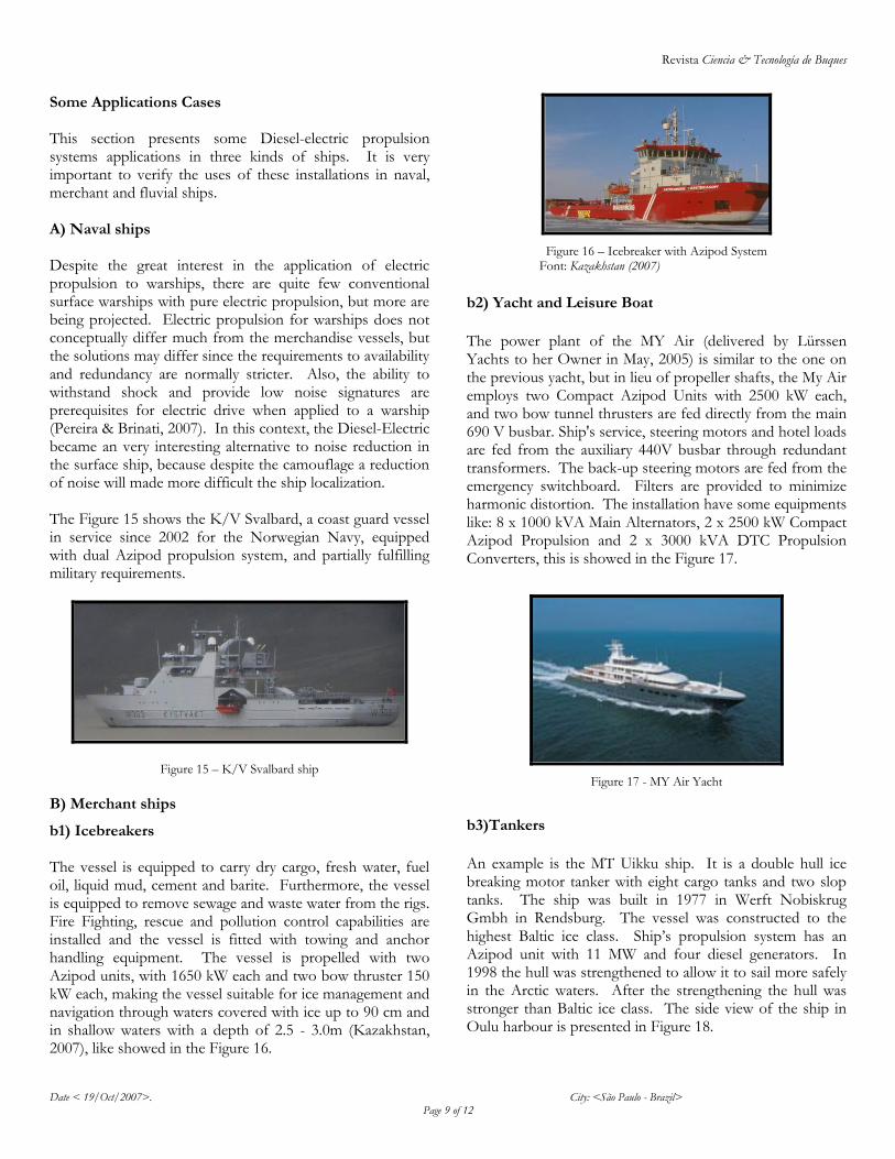
According Mishra (2005), ships that uses Azipod’s in general has less weight in relation with ships with conventional propulsion system. It results in less transversal stability, then it can induce roll movements in this ships, it cause a destabilization in the ship. Another aspect that skeg has an important paper in the protection of Azipod in the collision with floating objects and bottom canal. The Figure 9 shows an Azipod installation in a not conventional ship. This ship is a ferry, that operate in Finland Rivers and has a capacity to transport 350 passenger and 2 vehicles. Its dimensions are 33,30m, 8,80m and 3,00m (length, width and draft respectively). It has 2 Compact Azipod with power of 400 kW and achieves a speed of 11 knots.
Figure 9 –Hull shape in a ship not conventional
Crash Stop Turn
Revista Ciencia & Tecnología de Buques
Date < 19/Oct/2007>. City: <São Paulo - Brazil> Page 7 of 12
In the relation the disadvantages in the Azipod utilization, Gragen & Andersen (1997) cite that the system is efficient, but electric synchronous engines have high power and lower speed, that shows disadvantages in relation the size and weight, so are necessary more spaces to receipt the motor. In general, the pod size corresponding approachable 60% of propeller diameter , the propeller gas a relatively slow efficiency, like presented in Figure 10, that show the effect of relation pod diameter / propeller diameter about efficiency.
Figure 10 – Influence of pod diameter / propeller diameter
In the same research line, Heinke & Heinke (2003) make test in three types of pods with different configurations. These authors analyzed the diameter of gondola dG, in function of length of gondola – lG, and, the lg in relation propeller diameter – D, because they affirm that it is an important parameter to quantify the efficiency of propulsive system. It verified that an improvement in the pod length results in an additional thrust and torque in the propeller, but this cause a reduction in the efficiency total of system, like shows in the Figure 11. So, the ratio between total thrust and propeller diameter is lower when pod diameter is bigger. Another disadvantage of this system in relation the Diesel propulsion is the acquisition cost of equipments. For example, in case of big ships like Ropax and cruiser, the cost of Azipod can be approximately €12 million more expensive in relation with a conventional propulsion system. This increment in the acquisition ship cost is applicably to Ropax ships and cruiser quoted in €100 million and €400 millions respectively.
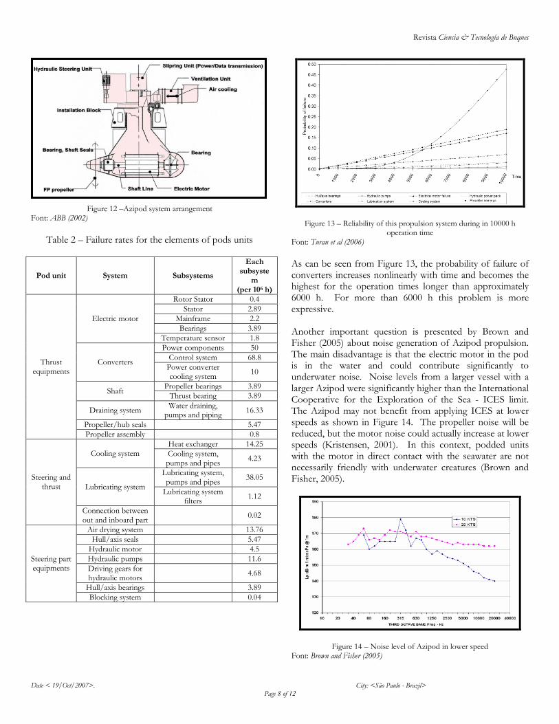
Figure 11 – Relation between length and diameter pod On the other hand, Turan et al (2006) show some problems in the use of Azipod encountered in shipping operations. The biggest portion of these problems are encountered in cruiser ships. A very important aspect is reliability and the maintainability of ship. They present a reliability analysis of main equipments of Azipod. Figure 12 shows these equipments. They investigated the qualitative and quantitative risk assessments, the crucial components that lead to the failure of the pod system have been identified and the effectiveness of the risk control options such as having redundant subsystems for crucial components have been evaluated. These aspects have a relation with equipments show in Figure 13. They developed a structure of fault trees for inclusion of the subsystems/equipment, which cause system effects of “loss of steering” and ‘loss of propulsion” for the rotating pod. The time reliability calculated was carried out for operation time up to 10.000 h. During tests several dates were colleted about the failure this system and it is grouped in Table 2 to 10000 h operation time and the probabilities of equipments failure are presented in Figure 12 to 6000 h operation time.
Revista Ciencia & Tecnología de Buques
Date < 19/Oct/2007>. City: <São Paulo - Brazil> Page 8 of 12
Figure 12 –Azipod system arrangement Font: ABB (2002)
Table 2 – Failure rates for the elements of pods units
Pod unit System Subsystems
Each subsyste
m (per 106 h)
Thrust equipments
Electric motor
Rotor Stator 0.4
Stator 2.89
Mainframe 2.2
Bearings 3.89
Temperature sensor 1.8
Converters
Power components 50
Control system 68.8
Power converter cooling system
10
Shaft Propeller bearings 3.89
Thrust bearing 3.89
Draining system Water draining,
pumps and piping 16.33
Propeller/hub seals 5.47
Propeller assembly 0.8
Steering and thrust
Cooling system
Heat exchanger 14.25
Cooling system, pumps and pipes
4.23
Lubricating system
Lubricating system, pumps and pipes
38.05
Lubricating system filters
1.12
Connection between out and inboard part
0.02
Steering part equipments
Air drying system 13.76
Hull/axis seals 5.47
Hydraulic motor 4.5
Hydraulic pumps 11.6
Driving gears for hydraulic motors
4.68
Hull/axis bearings 3.89
Blocking system 0.04
Figure 13 – Reliability of this propulsion system during in 10000 h operation time
Font: Turan et al (2006)
As can be seen from Figure 13, the probability of failure of converters increases nonlinearly with time and becomes the highest for the operation times longer than approximately 6000 h. For more than 6000 h this problem is more expressive. Another important question is presented by Brown and Fisher (2005) about noise generation of Azipod propulsion. The main disadvantage is that the electric motor in the pod is in the water and could contribute significantly to underwater noise. Noise levels from a larger vessel with a larger Azipod were significantly higher than the International Cooperative for the Exploration of the Sea - ICES limit. The Azipod may not benefit from applying ICES at lower speeds as shown in Figure 14. The propeller noise will be reduced, but the motor noise could actually increase at lower speeds (Kristensen, 2001). In this context, podded units with the motor in direct contact with the seawater are not necessarily friendly with underwater creatures (Brown and Fisher, 2005).
Figure 14 – Noise level of Azipod in lower speed Font: Brown and Fisher (2005)
Revista Ciencia & Tecnología de Buques
Date < 19/Oct/2007>. City: <São Paulo - Brazil> Page 9 of 12
Some Applications Cases This section presents some Diesel-electric propulsion systems applications in three kinds of ships. It is very important to verify the uses of these installations in naval, merchant and fluvial ships. A) Naval ships Despite the great interest in the application of electric propulsion to warships, there are quite few conventional surface warships with pure electric propulsion, but more are being projected. Electric propulsion for warships does not conceptually differ much from the merchandise vessels, but the solutions may differ since the requirements to availability and redundancy are normally stricter. Also, the ability to withstand shock and provide low noise signatures are prerequisites for electric drive when applied to a warship (Pereira & Brinati, 2007). In this context, the Diesel-Electric became an very interesting alternative to noise reduction in the surface ship, because despite the camouflage a reduction of noise will made more difficult the ship localization. The Figure 15 shows the K/V Svalbard, a coast guard vessel in service since 2002 for the Norwegian Navy, equipped with dual Azipod propulsion system, and partially fulfilling military requirements.
Figure 15 – K/V Svalbard ship
B) Merchant ships
b1) Icebreakers The vessel is equipped to carry dry cargo, fresh water, fuel oil, liquid mud, cement and barite. Furthermore, the vessel is equipped to remove sewage and waste water from the rigs. Fire Fighting, rescue and pollution control capabilities are installed and the vessel is fitted with towing and anchor handling equipment. The vessel is propelled with two Azipod units, with 1650 kW each and two bow thruster 150 kW each, making the vessel suitable for ice management and navigation through waters covered with ice up to 90 cm and in shallow waters with a depth of 2.5 - 3.0m (Kazakhstan, 2007), like showed in the Figure 16.
Figure 16 – Icebreaker with Azipod System Font: Kazakhstan (2007)
b2) Yacht and Leisure Boat
The power plant of the MY Air (delivered by Lürssen Yachts to her Owner in May, 2005) is similar to the one on the previous yacht, but in lieu of propeller shafts, the My Air employs two Compact Azipod Units with 2500 kW each, and two bow tunnel thrusters are fed directly from the main 690 V busbar. Ship's service, steering motors and hotel loads are fed from the auxiliary 440V busbar through redundant transformers. The back-up steering motors are fed from the emergency switchboard. Filters are provided to minimize harmonic distortion. The installation have some equipments like: 8 x 1000 kVA Main Alternators, 2 x 2500 kW Compact Azipod Propulsion and 2 x 3000 kVA DTC Propulsion Converters, this is showed in the Figure 17.
Figure 17 - MY Air Yacht
b3)Tankers
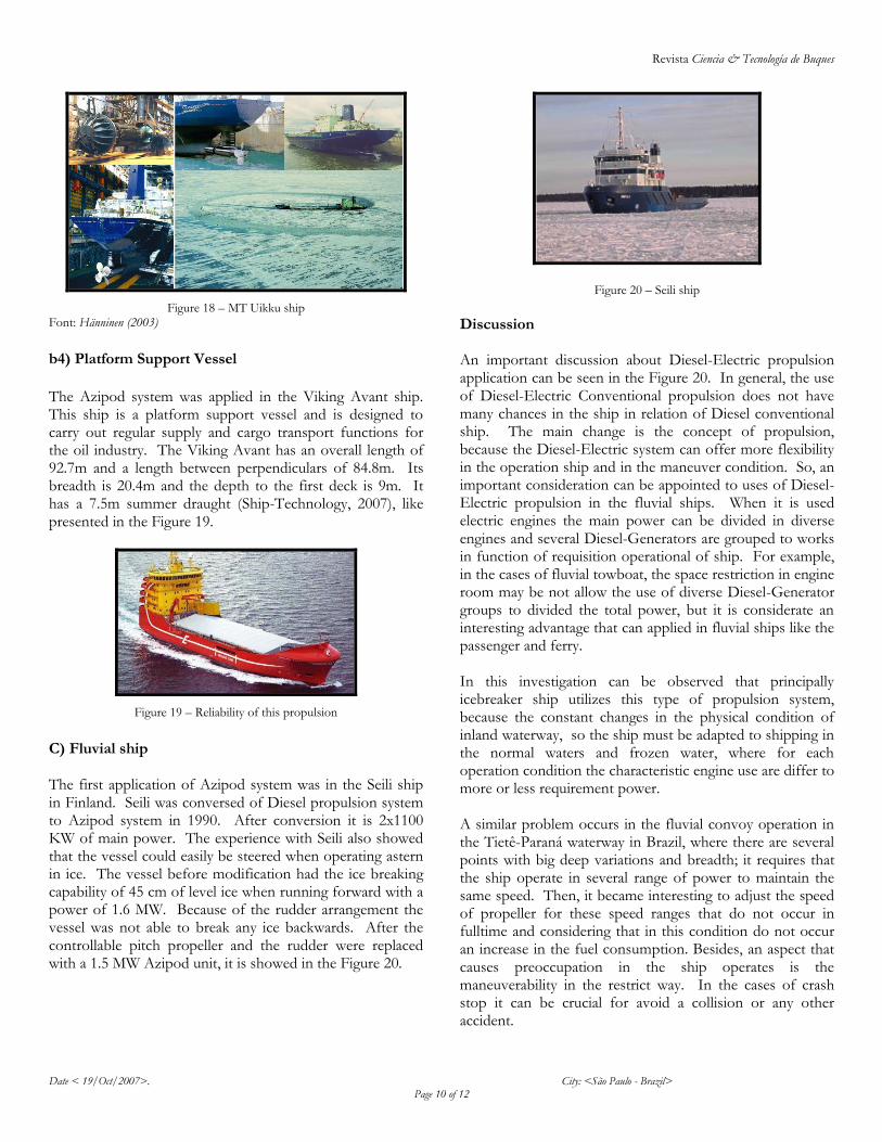
An example is the MT Uikku ship. It is a double hull ice breaking motor tanker with eight cargo tanks and two slop tanks. The ship was built in 1977 in Werft Nobiskrug Gmbh in Rendsburg. The vessel was constructed to the highest Baltic ice class. Ship’s propulsion system has an Azipod unit with 11 MW and four diesel generators. In 1998 the hull was strengthened to allow it to sail more safely in the Arctic waters. After the strengthening the hull was stronger than Baltic ice class. The side view of the ship in Oulu harbour is presented in Figure 18.
Revista Ciencia & Tecnología de Buques
Date < 19/Oct/2007>. City: <São Paulo - Brazil> Page 10 of 12
Figure 18 – MT Uikku ship Font: Hänninen (2003)
b4) Platform Support Vessel
The Azipod system was applied in the Viking Avant ship. This ship is a platform support vessel and is designed to carry out regular supply and cargo transport functions for the oil industry. The Viking Avant has an overall length of 92.7m and a length between perpendiculars of 84.8m. Its breadth is 20.4m and the depth to the first deck is 9m. It has a 7.5m summer draught (Ship-Technology, 2007), like presented in the Figure 19.
Figure 19 – Reliability of this propulsion
C) Fluvial ship
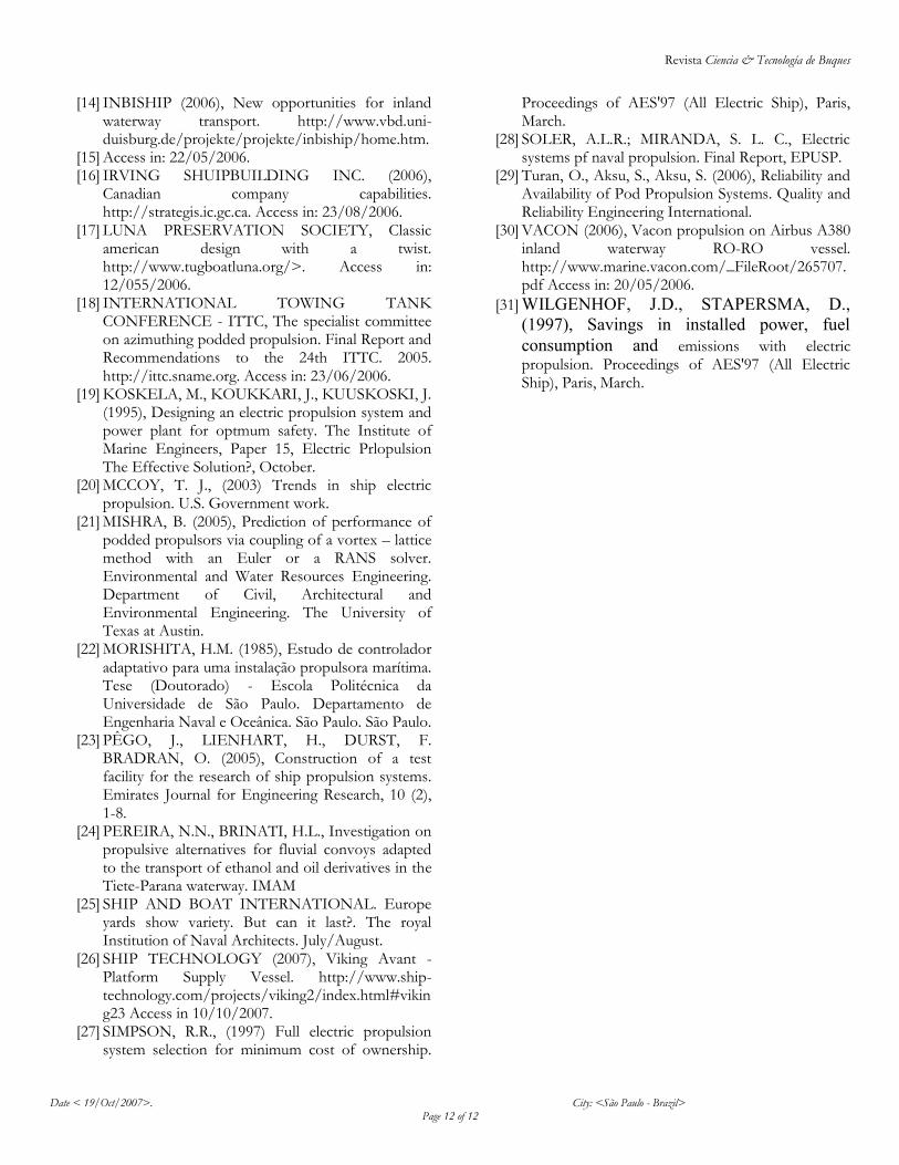
The first application of Azipod system was in the Seili ship in Finland. Seili was conversed of Diesel propulsion system to Azipod system in 1990. After conversion it is 2x1100 KW of main power. The experience with Seili also showed that the vessel could easily be steered when operating astern in ice. The vessel before modification had the ice breaking capability of 45 cm of level ice when running forward with a power of 1.6 MW. Because of the rudder arrangement the vessel was not able to break any ice backwards. After the controllable pitch propeller and the rudder were replaced with a 1.5 MW Azipod unit, it is showed in the Figure 20.
Figure 20 – Seili ship
Discussion An important discussion about Diesel-Electric propulsion application can be seen in the Figure 20. In general, the use of Diesel-Electric Conventional propulsion does not have many chances in the ship in relation of Diesel conventional ship. The main change is the concept of propulsion, because the Diesel-Electric system can offer more flexibility in the operation ship and in the maneuver condition. So, an important consideration can be appointed to uses of Diesel-Electric propulsion in the fluvial ships. When it is used electric engines the main power can be divided in diverse engines and several Diesel-Generators are grouped to works in function of requisition operational of ship. For example, in the cases of fluvial towboat, the space restriction in engine room may be not allow the use of diverse Diesel-Generator groups to divided the total power, but it is considerate an interesting advantage that can applied in fluvial ships like the passenger and ferry. In this investigation can be observed that principally icebreaker ship utilizes this type of propulsion system, because the constant changes in the physical condition of inland waterway, so the ship must be adapted to shipping in the normal waters and frozen water, where for each operation condition the characteristic engine use are differ to more or less requirement power. A similar problem occurs in the fluvial convoy operation in the Tietê-Paraná waterway in Brazil, where there are several points with big deep variations and breadth; it requires that the ship operate in several range of power to maintain the same speed. Then, it became interesting to adjust the speed of propeller for these speed ranges that do not occur in fulltime and considering that in this condition do not occur an increase in the fuel consumption. Besides, an aspect that causes preoccupation in the ship operates is the maneuverability in the restrict way. In the cases of crash stop it can be crucial for avoid a collision or any other accident.

Revista Ciencia & Tecnología de Buques
Date < 19/Oct/2007>. City: <São Paulo - Brazil> Page 11 of 12
However, it can be discussible the flexibility of allocation engines in others compartments in the ship; in towboats this parameter is very important, because it can offer advantages in two aspects. In first place, this process tends to facilitate the inspection and maintenance of motors. Generally, this type of ships presents small spaces for the engine rooms that, in some cases, difficult the inspection and reparation. In second place, it should be considerate that DE propulsion system arrangement must be subordinate at the arrangement of ship. The stability question also is very important and must be evaluated with carefully, so must be observed the requirement to maintain the longitudinal and transversal equilibrium. In other hand, the Azipod propulsion system need of some alteration in the conception of ship principally in the hull’s ship. However the first system had been installed in a fluvial ship, nowadays, its application are concentrate in big ships like cruiser, LNG, container, tanker and supply-boat. In the Europe there are some fluvial ships that use Azipod system propulsion. There are many advantages presented for several authors, but this system is very expansive and it can difficult its expansion. Finally, other important question refers the crew in this type of ship, because modern propulsion systems require people trained to operate these systems. Then a constant training is necessary for the crew ship. Conclusion The conclusions obtained from this study are as follows: (1) The Diesel-Electric propulsion system can be applied in diverse type of ships and can offer a good condition of steering and maneuverability. The advantages are very expressive when compared with Diesel conventional propulsion system, but are necessary changes in hull shape of ship to uses of Azipod. It must be evaluated to quantify the advantages in change a conventional ship to DE propulsion system. However, the costs of these plants are bigger in relation to Conventional Diesel propulsion. In relation with the operational level safety, it tends to be more significance when compared with Diesel mechanic. (2) In general the manufacturer shows only the advantages of this system, but some authors present some problems encountered in the use the Azipod system. Like this system is relatively new, others studies are been realized to analyses with deeper the problems showed for this system. References
[1] ARPIAINEN, M.; JUURMAA, K.; LAUKIA, K.; NIINI, M.; JARVINEN, K., NOBLE, P.,(1993) Naval Architecture of Electric Ships – Past, Present and Future, SNAME Transactions, Vol. 101, pp. 583-607.
[2] ASEA BROWN BOVERI – ABB (2002), Reliable marine propulsion. 3BFV000245R01 REV E © ABB Oy, Marine and Turbocharging, ADAMS OY/F.G. Lönnberg. Access in: http://www.abb.com/marine.
[3] BORMAN, J.B., SHARMAN, B.P. (1995), Electric propulsion – a view from a classification society. The Institute of Marine Engineers, Paper 11, Electric Propulsion The Effective Solution?, October,
[4] BLOKLAND, A.J., EBLING, G.H., (1995) Protection of an integrated energy system. The Institute of Marine Engineers, Paper 17, Electric Propulsion The Effective Solution?, October.
[5] CREATING INLAND NAVIGATION (2006), Fuel cell technology in inland navigation. Technical report in the framework of EUA project creating (M06.02).
[6] DEPARTMENT OF ELECTRICAL ENGINEERING UNITED STATES NAVAL ACADEMY. (2006), Marine electric drive overview. http://www.usna.edu/EE/ee331/Handouts/Electric_Drive.pdf. Access in: 23/06/2006.
[7] FISHER, R.W., Brown, N.A. (2005), Factors affecting the underwater noise of commercial vessels operating in environmentally sensitive areas. OCEANS.
[8] FKI – INDUSTRIAL SYSTEMS (2006), Drives power novel electric trimaran warship. Disponível em: http://www.engineeringtalk.com. Access in: 30/07/2006.
[9] GRAGEN, U., ANDERSEN, P. (1997), New type of permament field machines for diesel electric propulsion systems. Proceedings of AES'97 (All Electric Ship), Paris, March.
[10] GUIMARÃES, L.S., (1999), Sintese de doutrina de segurança para projeto e operação de submarinos nucleares. Tese (Doutorado) - Escola Politécnica da Universidade de São Paulo. Departamento de Engenharia Naval e Oceânica. São Paulo. São Paulo.
[11] HANSEN, J.F.; LYSEBO, R.. (2004), Electric Propulsion for LNG Carriers. LNG Journal, pp. 12, September, 2004
[12] .HEINKE, C., HEINKE, H. (2003), Investigations about the use of podded drives for fast ships. FAST 2003. Ischia. Italia.
[13] KAZAKHSTAN W. (2007), IBSV ANTARTICABORG.
Revista Ciencia & Tecnología de Buques
Date < 19/Oct/2007>. City: <São Paulo - Brazil> Page 12 of 12
[14] INBISHIP (2006), New opportunities for inland waterway transport. http://www.vbd.uni-duisburg.de/projekte/projekte/inbiship/home.htm.
[15] Access in: 22/05/2006. [16] IRVING SHUIPBUILDING INC. (2006),
Canadian company capabilities. http://strategis.ic.gc.ca. Access in: 23/08/2006.
[17] LUNA PRESERVATION SOCIETY, Classic american design with a twist. http://www.tugboatluna.org/>. Access in: 12/055/2006.
[18] INTERNATIONAL TOWING TANK CONFERENCE - ITTC, The specialist committee on azimuthing podded propulsion. Final Report and Recommendations to the 24th ITTC. 2005. http://ittc.sname.org. Access in: 23/06/2006.
[19] KOSKELA, M., KOUKKARI, J., KUUSKOSKI, J. (1995), Designing an electric propulsion system and power plant for optmum safety. The Institute of Marine Engineers, Paper 15, Electric Prlopulsion The Effective Solution?, October.
[20] MCCOY, T. J., (2003) Trends in ship electric propulsion. U.S. Government work.
[21] MISHRA, B. (2005), Prediction of performance of podded propulsors via coupling of a vortex – lattice method with an Euler or a RANS solver. Environmental and Water Resources Engineering. Department of Civil, Architectural and Environmental Engineering. The University of Texas at Austin.
[22] MORISHITA, H.M. (1985), Estudo de controlador adaptativo para uma instalação propulsora marítima. Tese (Doutorado) - Escola Politécnica da Universidade de São Paulo. Departamento de Engenharia Naval e Oceânica. São Paulo. São Paulo.
[23] PÊGO, J., LIENHART, H., DURST, F. BRADRAN, O. (2005), Construction of a test facility for the research of ship propulsion systems. Emirates Journal for Engineering Research, 10 (2), 1-8.
[24] PEREIRA, N.N., BRINATI, H.L., Investigation on propulsive alternatives for fluvial convoys adapted to the transport of ethanol and oil derivatives in the Tiete-Parana waterway. IMAM
[25] SHIP AND BOAT INTERNATIONAL. Europe yards show variety. But can it last?. The royal Institution of Naval Architects. July/August.
[26] SHIP TECHNOLOGY (2007), Viking Avant - Platform Supply Vessel. http://www.ship-technology.com/projects/viking2/index.html#viking23 Access in 10/10/2007.
[27] SIMPSON, R.R., (1997) Full electric propulsion system selection for minimum cost of ownership.
Proceedings of AES'97 (All Electric Ship), Paris, March.
[28] SOLER, A.L.R.; MIRANDA, S. L. C., Electric systems pf naval propulsion. Final Report, EPUSP.
[29] Turan, O., Aksu, S., Aksu, S. (2006), Reliability and Availability of Pod Propulsion Systems. Quality and Reliability Engineering International.
[30] VACON (2006), Vacon propulsion on Airbus A380 inland waterway RO-RO vessel. http://www.marine.vacon.com/_FileRoot/265707.pdf Access in: 20/05/2006.
[31] WILGENHOF, J.D., STAPERSMA, D.,
(1997), Savings in installed power, fuel
consumption and emissions with electric propulsion. Proceedings of AES'97 (All Electric Ship), Paris, March.