197011_020_DSİ_Teknik Bülten.pdf
56
. .. TEKNIK BULTEN 20 YAYlN KURULU Dr. Y. Müh. Fuat Y. Müh. Vladmir MIHAILOF Y. Müh. Yüksel SAYMAN V. Müh. Fuat BAYAZIT V. Müh. lsmail TANRlVERDI V. Müh. Ahmet ÜNVER 1970 iÇiNDEKiLER BETONARME DEMIRLERININ KOROZVONUNA ETKI YAPAN MUHTELIF FAKTÖRLER EFFECT OF VARIOUS FACTORS ON THE CORROSION OF REINFORCING STEEL IN CONCRETE V. Müh. Ömer L. BAYAZil V. Müh. Hayri YALÇIN FLUORESCEIN ILE YAPILAN BOYA DENEVLERINDE AERUGINOSA PSEDUMONAS BAKTERISINiN ETKILERI THE INFLUENCES OF AERUGINOSA PSEUDOMONAS BACTERIA IN THE DYE EXPERIMENTS MADE WITH FLUORESCEIN • V. Müh. Hayri YALÇIN V. Müh. Metin SUCA UÇUCU KÜL IHTIVA EDEN ÇiMENTOLARA IILK KÜR SICAKLICININ ETKISI THE EFFECT OF TEMPERATURE DURING THE FIRST DAY ON THE MORTAR SAMPLES WHICH CONTAIN FLY ASH V. Müh. Sevim KOCAÇlTAK
-
Upload
cagri-karabillioglu -
Category
Documents
-
view
244 -
download
2
Transcript of 197011_020_DSİ_Teknik Bülten.pdf

. .. TEKNIK BULTEN
Sayı: 20
YAYlN KURULU
Dr. Y. Müh. Fuat ŞENTÜRK
Y. Müh. Vladmir MIHAILOF
Y. Müh. Yüksel SAYMAN
V. Müh. Fuat BAYAZIT
V. Müh. lsmail TANRlVERDI
V. Müh. Ahmet ÜNVER
Kasım 1970
iÇiNDEKiLER
BETONARME DEMIRLERININ KOROZVONUNA ETKI YAPAN MUHTELIF FAKTÖRLER EFFECT OF VARIOUS FACTORS ON THE CORROSION OF REINFORCING STEEL IN CONCRETE
V. Müh. Ömer L. BAYAZil V. Müh. Hayri YALÇIN
FLUORESCEIN ILE YAPILAN BOYA DENEVLERINDE AERUGINOSA PSEDUMONAS BAKTERISINiN ETKILERI THE INFLUENCES OF AERUGINOSA PSEUDOMONAS BACTERIA IN THE DYE EXPERIMENTS MADE WITH FLUORESCEIN•
V. Müh. Hayri YALÇIN V. Müh. Metin SUCA
UÇUCU KÜL IHTIVA EDEN ÇiMENTOLARA IILK KÜR SICAKLICININ ETKISI THE EFFECT OF TEMPERATURE DURING THE FIRST DAY ON THE MORTAR SAMPLES WHICH CONTAIN FLY ASH
V. Müh. Sevim KOCAÇlTAK

\
ll

Betonarme Demirlerinin Koroıyonuna Etki Yapan Muhtelif Faktörler
Hayri YALÇIN ıÖmer Lütfi SAVAZlT Kimya. Yük. Müh. lnş . Yüksek Müh.
Araştırma Dairesi Başkanlığı
ÖZET
Betonarme demirlerinin korozyonu beton yapının dayanıklığı ve ömrü bakımından çok önemli problemler hasıl etmektedir. Özellikle deniz atmos· feri veya korozif suların' etkisinde kalan betonlarda, betonarme demirleri şiddetle korozyona uğrayıp içsel gerilmelere ve çatlamalara sebep olmaktadır.
Demirin beton Içinde cereyan eden koroıyon mekanizması ana pren· sipler itibariyle elektrolit içindeki korozyona benzer karakterdedir. Beton bünyesi üzerine çevre şartlarından ileri gelen farklı elektrokimyasal etki· ler karşısında, betonarme demirlerinin muhtelif bölgeleri arasında elektro· potansiyel farkları meydana gelmektedir. Böylece teşekkül eden galvanik koroıyon hücrelerinde daha negatif elektropotansiyeli haiz olan bölgeler anat olarak çözünmektedir. Koroıyon hızı çevre elektriksel direncine ve bilhassa polarizasyon faktörüne bağlı kalmaktadır.
Teorik prensipleri açıklıkla bilinmesine rağmen, arazi şartlarında korozyonun elektrokimyasal şartlarının tesbiti ve koroıyon hızının kontrolü büyük güçlükler hasıl etmektedir. Buna sebep elektrolit olarak kabul edilen betonun çok değişik fiziksel ve kimyasal özellikler göstermesidir. Beton Içinde cereyan eden koroıyon reaksiyonu hızı genellikle katadik depolar!· zasyon yani oksijen difüzyonu ile kontrol edilmektedir. Şu halde betonarme demirlerinin satha olan uzaklığı. betonun porozite, permeabilite ve su doy.gunluğu gibi fiziksel özellikleri koroıyon olayının hızına etki yapan en önemli faktörleri teşkil etmektedir. Diğer taraftan koroıyon akımı çözelti içinde iyon hareketi ile taşındıöından, betonun ihtiva etmiş olduğu tuz yüz·desi koroıyon olayı bakımından önemli bir faktör sayılmaktadır.
Betonarme demirlerinin koroıyonuna betonun hazırl:mması, kürü, yapısı ve çevresinden ileri gelen bir çok taktör etki yapmaktadır. Bu makale· de, koroıyon olayına etki yapan her faktörün etkime şekli ve derecesi , korozyon reaksiyonunun elektrokimyasal kinetiği açısından ele alınarak ayrı .ayrı incelcnmektedir. Bu incelemelerden anlaşılmaktadır ki, malzeme seçi·
1

minde ve betondökümü sırasında itina edilmek suretiyle, porozite ve permeabilitesi düşük, dalayısile oksijen difüzyonu pratik şartlar içinde yeteri kadar az beton imali mümkündür.
Halen işletmede bulunan bir beton yapıda betonarme demirlerinin korozyonunun önlenmesi için tavsiye edilen en uygun metot beton sathının uygun koruyucu maddelerle kaplanmasıdır. Gerçekten, korozyon olayı için mutlaka oksijene ihtiyaç olduğundan, beton satıhlarının geçirimsiz bir madde ile kaplanması korozyon reaksiyonunun teorik olarak durmasını sağlamış olacaktır. Ancak pratik şartlar altında bir beton yapının bütün satıhlarını kapiayabiimek son derece güç ve bazı halde ise imkansızdır.
Pratikte koroıyondan korunmak için uygulama alanı bulan diğer bir metot, betonarme demirlerinin uygun bir koruyucu - genellikle çimento şerbeti - ile önceden kaplanmasıdır. Böylece metal sathına oksijen difüzyonu büyük ölçüde azaltılmış olmaktadır.
Korozyonun önlenmesi için en kesin ve rasyonel tedbir şüphesiz katodik korumadır. Özellikle kuvvet santralları, cebri borular, limanlar v.s. gibi bazı büyük inşaatlarda katadik koruma uygulanmaktadır. Korozyon etkilerini kesin şekilde önlemesi bakımından bu metot gittikçe önem kazanmaktadır.
1. GiRIŞ
Betonarme demirleri beton yapı için çok faydalı olmakla beraber bazr hallerde mahzurlu olabilir. Demirirı korozyonu sonucu hasıl olan korozyon ürünleri daha büyük hacim işgal ettiklerinden, beton yapı içinde gerilmeler meydana gelir. Bu içsel gerilmeler sonucu olarak beton yapı, betonarme çubukları boyunca çatlar ve parçalanır.
Pratikte bir çok hallerde, elektrokimyasal korozyon farklı bölgelerdeki yersel anodik ve katadik kısımlar arasında pil teşekkülü ile cereyan eder. Anot ve katot arasında iyonlar elektrolit (beton) içinden, elektronlar ise metalden geçerler. Korozyon reaksiyonunun toplam hızı verilen şartlar altında, muhtelif kademelerde ve fazlarda cereyan eden en yavaş olayın hızına bağlı kalır. (1)
Anat ve katot bölgeleri ara5ıııdaki potansiyel farkı sonucu galvanik hücre devresinden bir akım geçer ve FARADAY kanununa göre geçen akım miktarı ile metaldaki ağırlık kaybı doğru orantılıdır (*) . Koroıyon reaksiyonunun kinetiği anat ve katot polarizasyonu ve sistemin omik direncine bağlıdır.
Galvanik hücrelerde anotta çczünme devam ettikçe iyaniaşma reaksiyonu hızı gittikçe azalır. Metal iyonlarının beton kapiler boşluklarında bi-
2
1") Birinci FARADAY KANUNU : Bir eıektrollz devresinden 96496 kulon akım ııectlı'lınde, anot ve katotta bir cklvalent ııram madde cözOnOr veya metal haline donüşür.

rikmesi sonucu konsantrasyon polarizasyonu meydana gelir. Bunun dışında anadik çözünme reaksiyonunda en önemli engeli, demir elektrot potansiyelinin + 1,0 voltu geçmesi sonucu anot pasifleşmesi teşkil eder.
Katadik olayda polarizasyon, beton boşluklarını dolduran elektrolit içinden yeterli miktarda oksijen difüzlenememesl sonucu meydana gelir.
Betonarme demirlerinin koroıyon etkilerine dayanıkldığı ile beton yapının mukavemeti arasında çok yakın bağlantı vardır . Beton ne kadar i<Om· pakt ve geçirimsiz ise çevre etkilerine karşı demir çubukları korozyona uğramaktan korur. Aksine olarak beton yapı zayıf ve permeabilitesi yüksek ise, betonarme demirleri koroıyon etkilerine karşı son derece dayanıksızdır. Bu şartlar altında beton içine inhibitör maddeleri ilavesi bile korozyonu tam olarak önliyemez.
ll. KOROZVONUN MEKANiZMASI
1 - Elektrolit içinda koroıyon
Elektrolit içindeki korozyonu izah etmek üzere pekçok teori ortaya konulmuştur. Son zamanlarda birçok yazar, metal yüzeylerinde hasıl olan mikroskopik ga'lvanik hücrelerin korozyona sebep olduğu fikrinde birleş· mişlerdir. Bu galvanik hücreler metalin veya çevrenin homojen yapıda olmayışından ileri gelmektedir. (2) Bu kabul ilk defa isviçreli ilim adamı RiVE tarafından yapılmıştır.
Eğer birbiri ile irtibatlandırılmış iki farklı metal bir elektrolit içine daldırılırsa, bir pil teşekkül eder. Mamafih tek bir metal daldırılmış olsa bile, metal yüzeyinde kısa devreli galvanik hücreler hasıl olabilir. Metal yüzeyinde daha elektronegatif potansiyeli haiz kısımlar anot olur ve iyon halinde çözeltiye geçer. Metal yüzeyinde bu çeşit hücrelerden pek çok teşekkül eder. Metal yapımındaki herhangi bir gayri safiyet veya alaşım terkibindeki bir değişiklik, veya metalin hazırlanmasında farklı muameleye maruz kalmış kısımlar arasında bir potansiyel farkı doğabilir. Bundan başka metal yüzeyindeki oksit tabakasının mütecanis yapıda olmaması sebebiyle de bazan dikkate alınabilecek ölçüde bir potansiyel farkı meydana gelebilir.
Metalin içine daldırılmış olduğu elektrolitin akış hızı, çözünmüş gazlar ve diğer bazı faktörler de potansiyele etki yaparlar. Bu sebeple metal yüzeyi boyunca metal potansiyelinde farklılıklar hasıl olabilir. Böylece dış bağlantısı metalin kendisi olmak üzere muhtelif galvanik hücreler teşekkül eder. Bunların çok kısa mesafede olanlarına mikrohücreler adı veril ir.
1. 1. Galvanik kıorozyon hücreleri
Potansiyeli farklı olan iki metal bir elektrolit içine daldırılır ve dış devre teması sağlanırsa, galvanik bir hücre teşekkül eder. Potansiyeli daha
3

negatif olan anodu, diğeri katodu teşkil eder. Kirlenmiş bir metal yüzeyinde veya metal yapısındaki değişiklik bir metal üzerinde bile galvanik hücre meydana getirebilir.
Elektrolit içinde, metal yüzeyindeki anodik bölgelerin çözünmesi aşağıdaki denklemle gösterilebilir.
(n E. M"+) + m H20 + (M"+. m H20)
Açığa çıkan elektronlar anottan katoda dış devre yoluyla geçer.
nE ... ->- n Ec
Katot yüzeyine taşınan elektronlar orada bu elektronları kullanan bir olay cereyan etmez ise. katot bölgesinde birikirler. Böylece kısa sürede katot potansiyelinde negatif artış hasıl olur. Akım geçmesi sırasında elektrot potansiyelinde meydana gelen bu değişmeye polarizasyon denir.
Eğer katadda redükleyici bir olay vukubulur ise, katoda gelen elektronlar orada sarfedilir ve polarizasyon giderilmiş olur. Bu olaya da depolarizasyon denilir.
Katoddaki elektron absorbsiyonu genellikle aşağıda verilen iki yol ile vukubulur.
2H+ + 2E ->- 2H - >-H,
0 2 + 2H20 + 4E - >- 40H-
ilk reaksiyon hidrojen iyonlarının redüksiyonu ve hidrojen çıkışı ikincisi ise, oksijen gazının hidroksil iyonu haline gelişi katadik olayı teşkil eder. Katoddaki reaksiyon hızı ve çeşidi koroıyon olayı bakımından çok· önemli olup, katoddaki depolarizasyon, koroıyon reaksiyonunun temelini teşkil eder. Suda, havada, zemin ve beton içinde korozyonun devamı oksijen depolarizasyonu yoluyla vukubulur. Bu bakımdan oksijen difüzyonu korozyon hızına etki yapan en önemli faktörü teşkil eder.
Yukardaki iki reaksiyon daha yakından incelenirse, katoddaki hidrojen gazı çıkışının aşağıdaki kademelerden geçtiği görülür.
4
1 - Hidrate hidrojeh iyonlarının (H+ . mH20) katot bölgesine transferi
2 - Bu iyonların dehidratasyonu :
H+ . m H20 + H+ + m H20
3 - Hidrojen iyonlarının yükünü vermesi :
H++ E+ H
4 - Hidrojen moleküllerinin meydana gelişi :
H+ H+H2

5 - Katot bölgesinden hidrojen habbeciklerinin uzaklaşması ve di-füzyonu.
Oksijenin hidroksil haline gelmesi aşağıdaki kademelerden geçer :
1 - Oksijenin havadan katot bölgesine taşınması
a - Havadan elektrolite oksijen geçişi
b - Elektrolit içinde difüzyon
c - Katot civarındaki ince sıvı tabakasında ve katot yüzeyi üzerindeki film içinde difüzyon.
2 - Oksijenin iyontaşması
Oı + 2 HıO + 4 E-+ 4 OH-
Bu reaksiyon çeşitli çözeltiler içinde çeşitli potansiyellerde cereyan eder.
1. 2. Bir Galvanik Hücrede Polarizasyon
Yukarda akım geçtiği zaman r:~not ve katodun potansiyellerinin değiş
mekte olduğundan bahsedilmişti. Bir mikro hücrede devre kapanmadan önceki elektrot potansiyelleri ile, polarizasyon sebebiyle devre kapalı iken ölçülen potansiyel birbirinden farklıdır.
Anottaki polarizasyon, potansiyelin pozitif yönde artmasına sebep olur. Elektrot civarında çözünen metal iyonlarının konsantrasyonunun artması ve koruyucu tabaka teşekkülü ile anot polaı ize olur. Anot polarize olduğu zaman, yüksek akım yoğunluğunda başka bir reaksiyon meydana gelebilir. Mesela oksijen gazı çıkmağa başlar veya iyonlar daha yüksek değerli hale yükseltgenir.
Katot polarizasyonu, potansiyeli negatif yöne çevirir. Potansiyeldeki negatif sapma anottan gelen elektronların yığılması sebebiyledir. Katot potansiyelindeki bu negatif sapma. hidrojen iyonlarının miktarına veya katot yüzeyine oksijen difüzyonu hızına bağlıdır. Anot ve katottaki polarizasyon sebebiyle galvanik hücrelerde potansiyel farkı, bir müddet akım geçtikten sonra önemli ölçüde azalacaktır.
1. 3. Elektrolit içinde Korozyon Hızı
Anotta çözünen metal miktarı, FARADAY Kanununa göre geçen akım şiddeti ve zamana bağlıdır.
o = l.t Burada, O : Akım miktarı
: Akım şiddeti t : Zaman
5

Ohm kanununa göre
Burada,
E Elektromotor kuvveti
R Omik direnç
EK ve EA: Katot ve anat potansiyeli
R
EK ve EA yerine katot ve anodun akım geçmeden evvelki E°K ve E0 A değerleri konulur ve gerekli matematik işlemler yapılırsa, aşağıdaki formül elde edilir.
Burada
P K ve E0A = Katot ve anodun açık devre potansiyeli
PK ve PA = Katot ve anodun birim akımdaki polarizasyonu
R : Omik direnç
Bu denklem korozyon hızının hesaplanmasını mümkün kılan temel ifade olup muhtelif faktörlerin ve özellikle oksijen eksikliğinin korozyon üzerine etkisini izah eder. Buna rağmen , bu denklem ile korozyon hızını kanti· tatif olarak hesaplamak formülde geçen değerleri ayrı ayrı ölçmek güç olduğundan mümkün olmamaktadır.
2. Beton içinde Korozyon Mekanizması
Betonarme demirlerinin korozyonu üzerine yapılan çalışmalar, beton içinde korozyonun devam edebilmesi için mutlaka oksijenin mevcut olma· sı lazım geldiğini ortaya koymuştur. Demir, korozyon reaksiyonu sonucu genellikle demiraksit ve hidroksit haline gelir. Demiraksit demirden daha büyük bir hacim kaplar. Böylece beton içinde bir genleşme ve içsel ba· sınçlar doğar. Bu gerilmeler betonu çatiatmaya kafi gelecek kadar fazladır. Beton içine iyon hareketi olmaksızın meydana gelen bu hacim genleşmesi ancak oksijen difüzyonu ile izah edilebilir. Klorür iyonu veya diğer tuzlar korozyon mekanizması için etkili olmakla beraber mutlaka gerekli değildir .
Betonarme demirlerinin korozyonunda, en önemli hususu katot ve anot bölgelerine farklı konsantrasyonda oksijen difüzlenmesi teşkil eder. Farklı oksijen konsantrasyonunun meydana gelmesi şu iki yolla olur.
a) Beton yapının muhtelif bölgelerinde farklı çözüıımüş tuz muhtevası sebebiyle oksijen çözünürlüğü farklıdır.
6

b) Beton yapının muhtelif bölgelerinde farklı su doygunluğu sebebiyle havadan doğrudan oksijen difüzyonu farklı hızlarda olabilir.
Su içinde, özellikle deniz suyu içinde korozyonun nasıl cereyan ettiği aşağıdaki şekilde izah edilebilir. Beton yapının, suyun püskürmesine veya dalgalanmalarına maruz kaldığı bölgelerde beton yüzeyinde tuz birikmesi vukubulur. Zira su içinde buluna;ı tuzlar suyun buharlaşması sonucu beton yüzeyinde toplanır. Tuz miktarı dalga etkisi, rüzgar yönü ve kuvveti ve beton yapının biçimine göre muhtelif bölgelerde farklıdır. Yine bunun gini betonun muhtelif kısımlarının su doygunluğu da değişik olabilir. Setonun satıh özelliği - cilalı veya pürüzlü oluşu - rüzgar, güneş, rölatif rutubet ve su çizgisinden yüksekliğine göre betonun su doygunluğu yer yer değişiklik gösterir.
Beton sathında bulunan tuzlar kapilerler içine difüze olarak daha az konsantre olan boşluklara doğru çekilirler. Bunun sonucu olarak beton boşluklarındaki sular gittikçe daha tuzlu hale gelir. Su çizgisi üzerinde bulunan betonların su doygunluğu yüzden küçük olduğundan bu bölgelerde atmosferden oksijen difüzyonu daha kolaydır. Difüze olmuş oksijen kapiler boşlukl arı içindeki suda çözünür. Tuz yüzdesi az olan boşluk suyunda çözünmüş oksijen daha fazla, aksine olarak tuz yüzdesi çok olan bölgelerde daha azdır. Şu halde, beton içinde yüksek tuz/düşük oksijen ihtiva eden bölgeler anadik bölgeleri teşkil eder. Koroıyon bu bölgelerde vukubulur. Diğer taraftan düşük tuz/yüksek oksijen ihtiva eden bölgeler ise katadik bölgeleri meydana getirir.
Deniz suyu ile temas eden betonlarda koroıyon mekanizması biraz farklıdır . Deniz suyu tuzlarının mevcut olması oksijen çözünürlüğünü azaltır, buna karşılık omik direnci düşürür. Böylece galvanik akımların elektrolit içinden taşınması son derece kolaylaşır. Fazla tuz mevcudiyeti elektrolitin pH sını da düşürücü olarak rol oynar. Bilindiği gibi demir düşük PH larda korozyona daha dayanıksızdır.
3 - Su Altında Betonarme Demirlerinin Korozyonu
Betonarme demirlerinin korozyonu farklı oksijen konsantrasyonu sonucu meydana geldiğine göre su altında korozyonun devamı çok güçleşir. Zira bu durumda beton boşlukları tamamen su ile doludur ve havadan oksijen difüzyonu hemen hemen sıfırdır. Buna ra~men, bu durum korozyonun başlıca sebebinin farklı oksijen konsantrasyonundan ileri geldiği tezini çürütmez. Zira çok az oksijen konsantrasyonu olan bölgeler ile hiç oksijen ihtiva etmeyen bölgelerde farklı reaksiyonlar cereyan eder. Çelik yapının
suya gömülmüş kısımlarında demir iyonlarının çözeltiye geçmesini önle
yen sağlam bir koruyucu film teşekkül eder. Bu film klorür iyonları mev
cudiyetinde bile etkili bir koruma temin edebilir.
7

Beton içinde mevcut olan yüksek alkali ortamda farklı havalanmadan ileri gelen hücreler, ancak yüksek oksijen ihtiva eden ile düşük oksijen ihtiva eden bölgeler arasında teşekkül eder. Buna rağmen hiç oksijen ihtiva etmeyen ile yüksek oksijen ihtiva eden bölgeler arasında hücre faaliyeti mümkün değildir.
lll. ÇEŞiTLI FAKTÖRLERiN KOROZVON ÜZERiNE ETKiSi
Aşağıdaki faktörler betonarme demirlerinin koroıyonuna en çok etkiyen faktörler olarak düşünülebilir.
1. Beton Kalitesinin Etkisi
Önce ubeton kalitesi" teriminden ne anlaşıldığının açıklanması gerekir. Beton; kum, çakıl, kırma - çakıl veya herhangi tipdeki bir agreganın çimento su ve katkılarla karıştınlmasıyla meydana gelir. Esas bileşeni kalsiyum silikat ve alüminatlar olan çimento, su ile hidrate olarak sertleşir ve katılaşır. Betondaki agrega inertdir. Beton kalitesi aslında betonun bileşenleri ve karışımın kalitesi ile sınırlıdır. Fakat ayrıca betonun sıkıştırılması, kürü ve bilhassa korozif durumlarda kullanılan demir cinsi ile betonarme demiri üzerindeki betonun kalınlığı gibi diğer şartlar da beton kalitesi terimi içine girerler. Bu bakımdan burada tek tek veya müşterek olarak korozyona etkiyen faktörler incelenecektir.
1.1 - Bileşenlerin kalitesinin etkisi
1.1.1. Çimento
Genellikle yüksek kaliteli çimento kullanıldığı zaman betonarme demirlerinin korozyona karşı daha iyi korunduğu düşünülmektedir. Bu hususun doğruluğu bazı araştırmalarda gösterilmiştir. (3). Mesela; 10 mm örtü betonuna sahip numunelerden dökümden 4 yıl sonra; yüksek kaliteli partiand çimentosuyla yapılanlarda, 6 mm derinliğe kadar karbonizasyon ve betonarme demiri yüzeyinde % 35 pasianma görüldüğü halde, yüksek
kaliteli cüruf çimentosuyla yapılanlarda bu değerler sırasıyla 21 mm ve
% 68 dir.
Beton örtüsünün fiziki yahut kimyasal erozyonu sonucunda betonarme demirinde meydana gelen korozyonda çimento önemli bir rol oynamakta
dır (4) . Bu bakımdan alkali- agrega reaktivitesi düşük olan ve deniz suyu yahut sülfatlı su ve zeminlere dayanıklı tipde özel çimentoların kullanıl
ması tavsiye edilmektedir. Ayrıca bu tip inşaatlarda beton yapısında boş
luklar, kılcal damarlar ve beton bozukluklarının olmaması ayrıca önem kazanmaktadır.
8

1.1.2. Bileşenterin sebep olduğu porozite
Setonun sertleşmesi ve kuruması esnasında, kullanılan çimento cins ve kalitesine bcığlı olarak dahili gerilmeler meydana gelmektedir. Bu gerilmeler sonucu betonda, korozyona sebep olan elemanların içeri girmesine yarayan mikro- çatlaklar hasıl olur. Aynı şekilde bazı hafif agregaların kullanılması poroziteyi artıracağı cihetle korozyonu hasıl edici elemanların beton bünyesine taşınması için ılave kanalcıklar meydana gelir. Ancak 50 ı..r. m den daha küçük çaplı olan va ilk bir kaç gün içinde meydana gelen mikro çatlaklar daha sonra genişlemezler ve harici yükler altında büyümezler. Hatta bunların sonraki günlerdeki hidratasyon reaksiyonu ile doldurulması bile mümkündür. Bu düşünce tarzı, hidratasyon elemanlarının ulaşılabilir boşluklar ve sıvı ile dolu çatlaklar istikametinde büyüdüğü hipotezine dayanmaktadır (S).
Bu sebepten bazı agregalardaki büyük ve devamlılık gösteren boşlukların ilave olarak beton karışımına katılan çok ince füller ile daldurulması yoluna gidilmektedir. Böylece ayni zamanda agrega yüzeyi ile çimento hamuru arasındaki adeziyon kuvveti de artırılmış olmaktadır.
1.1.3. Katkılar
Çeşitli katkıların (bilhassa k!orür ve sülfat ihtiva eden) beton özellikleri üzerine etkileri hakkında çok çeşitli ve detaylı çalışmalar yapılmasına rağmen bugüne kadar betonarme demirindeki korozyona mani olan katkılar hakkındaki araştırmalara pek rastlanmamaktadır. Ancak bazı arcıştıncıların çalışmalarında çok küçük miktarlarda sodyum nitrit, potasyum kromat yahut sodyum benzoat kullanılması halinde % 2 ye kadar CaCI2 ihtiva eden betonarme yapılarda korozyona karşı oldukça iyi sonuçlar alındığına dair bilgilere rastlanmaktadır (6).
1. 2. Karışım Şeklinin Etkisi
Karışımda kullanılacak malzemelerin seçimi yapıldıktan sonra bir be
ton mühendisinin beton kalitesini iyileştirmek için önünde üç imkan vardır. Bunlar malzemeleri en iyi şeıkilde oranlıyarak kullanmak, uygun bir
sıkıştırma tekniği uygulamak ve betonu dökümden sonra iyi bir küre tabi
tutmaktır. Karışını oranının tayini muhtelif metodlar veya mühendisin tec
rübesine göre yapılır. Sıkıştırma oldukça kısa bir süre içinde tatbik edilir.
Kür en sonra gelen ve uzun bir müddet devam edecek olan önemli bir ko
nudur. Burada şunu unutmamalıdır ki, eğer bir karışımda iyi bir oranlama
yoksa ve iyi bir sıkıştırma tatbik edilmemişse, kür optimum bir şekilde
yapılsa dahi diğerlerinden dolayı kalitede meydana gelecek düşüklüğü
telafi edemiyecektir.
9
1.2.1. - Karışım Özellikleri
Kullanılan çimento miktarı , agreganın derecelenmesi ve su - çimento oranının koroıyon üzerinde önemli etkileri vardır. Bunlardan çimento miktarı korozyona sebep olan elemanların beton içine nüfuzunu kolaylaştıran çatlakları hasıl etme bakımından ikinci derecede bir rol oynar. Agreganın maksimum çapının da birinci derecede bir etkisi yoktur. Fakat bazan maksimum çapın azalmasıyla koroıyon hızında artmaya rastlanmaktadır. Bu halde tesir rötrcnin artması dolayısiyle mikro- çatlakların ve permeabilitenin artması şeklinde olmaktadır. Gerçekten maksimum çap küçüldükçe porozite değeri artış göstermektedir. Mesela deneylerda maksimum çapın 45 mm den 3 mm ye indirilmesiyle permeabilitede orijinal değere göre 2 - 5 defa bir artış görülmektedir.
Su - çimento oranının iyi bir sıkıştırma için minimum değerde tutulması gerekir. Karışırndaki su miktarının fazla olması sadece beton örtüsümin toplam porozitesini artırmakla kalmıyacak, ayni zamanda maksimum boşluk ebadlarının artmasına da yol açacaktır.
1.2.2. Taze Setonun Özellikleri
• Sertleşmeden evvelki sıkıştırılmış taze betonun da koroıyon üzerinde etkisi vardır.
Betonda hava katkı maddesi kullanılması, böylece oksijen yahut diğer korozyona etkiyen reaktif ve gazl arın içerde depo edilmesi, ayrışma ve oturma sebebiyle makro - boşlukların meydana gelişi , betonarme dernil"inin altında sıvı birikmesi gibi olaylar betonun plastik durumunda meydana gelirler. Bunlar ise sertleşmiş betonun kalitesine etkiyen önemli hu-' suslardır (7) .
Hava katkılı betonların plastik durumundaki oksijen miktarı sadece anadik değil katadik koroıyon mekanizması iç inde önemlidir. Böyle bir ortamdaki oksijen mevcudiyeti, demirin pasifleşme limit i a ltında anadik korozyon hızını artırmakta fakat katadik hidrojen çıkış hızını azaltmaktadır .
1.3 - Kürün Rolü
Bugüne kadar korozyonla ilgili olarak betonarme yapılarda görülen zarar ve yıkıntırarda birinci derecede sorumlu olarak beton örtünün fi zi ki yapısı gösterilmiştir . Beton örtülerinde görülen boşluk ve çat l ak l arın meydana ge liş sebebi ise, döküm şartları , iklim şartları yahut da yükleme durumuna dayanmaktadır.
iklim şartları, betonun özellikle dökümden sonraki ilk günlerinde çok farklı sıcaklık ve rutubet değişimlerine ve çok çabuk kurumaya maruz bırakılması halinde önem kazanır. Fabrikasyon şeklindeki imaliHda müm-
10

kün olduğu kadar kısa zaman içinde yüksek bir mukavemet istendiğinde
kürün zararları daha da artar. Normal betonarme betonunda da ilk 28 gün içinde standarda göre uygun bir ki.ırün sağlanması gerekir.
1.3.1 - Küring Şartları
Bilhassa başlangıçtaki kür sırasında çevre şartlarının korozyon üzerindeki etkisi, karışım oranı, çimento miktarı, agrega granülometrisi gibi diğer faktörlerden çok daha fazladır. Deneylerde, ayni karışım ve şartlarda imal edilmiş betonlarda; başlangıçtaki küring durumuna göre çok farkir hava permeabiliteleri elde edildiği gösterilmiştir. Dökümü yapılan betonarme elemanlarında korozyona karşı alınacak en iyi tedbir betonun şiddetli ve hızlı kurumasına karşı muhafazasıy!a mümkün olabilmektedir.
1.3.2 - Sertleşmiş betondaki çatlakların sebeb olduğu zararlar
Beton örtüsündeki rötre yahut büzülme gerilmelerinin sebep olduğlf çatlaklar korozyon üzerinde oldukça etkili bir rol oynarlar. Beton yapılarda mümkün olduğu kadar homojenliğin sağlanması için gayet iyi ve dikkatli bir döküm yapılması lazım gelir.
Aslında betondan, korozyon kimyası ve korozyon fiziğinin istedikleri arasında çelişkiler vardır. Mesela korozyonun kimyasal reaksiyonlarını
gözönüne alırsak yüksek çimento dozajı kullanmak gerekir. Halbuki dozajın artırılması suretiyle rötre çatlakların meydana gelme ihtimali artmaktadır . Korozyon reaksiyonunda korozyona sebep olan bu çatlaklardan kaçınmak için düşük dozajlı bir karışım daha uygun olacaktır. Ancak bu arada düşük dozajlı harçların makro boşluklara, ayrışmalara ve su dolu hücrelerin teşekkülüne sebep olduğu da gözönünde tutulmalıdır.
1.4 - Sertleşmiş betondaki diğer özellikler :
Sertleşmiş çimento hamurunun fiziki özellikleri de korozyon hızına
etkimektedir. Betonarme demirinin korozyonu için çimento daneciklerinin % 100 oranında hidrate olduğu hidratasyon reaksiyonlarının son bölümü önem kazanmaktadır. Bu fazda çimento hamuru oldukça büyük bir miktarda serbest yerlere sahip, boşluklu katı bir kütleden ibarettir. Bu serbest yerler. içinde çözünmüş katı maddeler bulunan su ve hava ile doludur. Çimento hamuru bu halde hava ve suyun geçişi için oldukça müsaittir ve yüksek bir elektriki resistiviteye sahiptir.
1.4.1 - Porozite
Porozite bir beton içindeki boşluk hacminin bütün hacme oranı olarak tarif edilir. Çimento hamuru içinde iki tip boşluk söz konusudur. Bunlardan birisi jel danecikleri arasındaki küçük boşluklar, d iğeri ise, jel dane-
11
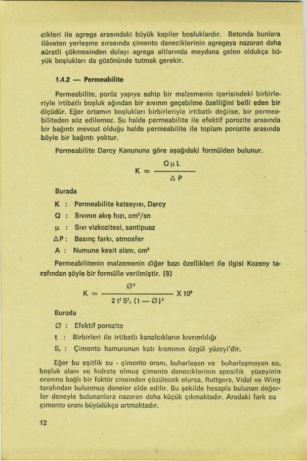
<:ikleri ile agrega arasındaki büyük kapiler bosluklardır. Setonda bunlara ilaveten yerleşme sırasında çimento daneciklerinin agregaya nazaran daha süratli çökmesinden dolayı agrega altlarında meydana gelen oldukça büyük boşlukları da gözönünde tutmak gerekir.
1.4.2 - Permeabilite
Permeabilite, poröz yapıya sahip bir malzemenin içerisindeki birbirleriyle irtibatlı boşluk ağından bir sıvının geçebilme özelliğini belli eden bir -ölçüdür. Eğer ortamın boşlukları birbirleriyle irtibatlı değilse , bir permeabiliteden söz edilemez. Şu halde permeabilite ile efektif porozite arasında bir bağıntı mevcut olduğu halde permeabilite ile toplam porozite arasında böyle bir bağıntı yoktur.
Permeabilite Darcy Kanununa göre aşağıdaki formülden bulunur.
0~-J.L K=
Burada
K Permeabilite katsayısı, Darcy
Q Sıvının akış hızı, cm3/sn
1-J. Sıvı vizkozitesi, santipuaz
D. P : Basınç farkı, atmosfer
A : Numune kesit alanı, cm2
Permeabilitenin malzemenin eliğer bazı özellikleri ile ilgisi Kozeny ta
rafından şöyle bir formülle verilmiştir. (8)
03 K = -------- X 108
Burada
0 : Efektif porozite
t : Birbirleri ilc irtibatlı kanalcıkların kıvrımlılığı
Sv : Çimento hamurunun katı kısmının özgül yüzeyi'dir.
Eğer bu eşitlik su - çimento oranı, buharlaşan ve buharlaşmayan su, 'boşluk alanı ve hidrate olmuş çimento daneciklerinin spesifik yüzeyinin oranına bağlı bir faktör cinsinden çözülccck olursa. Ruttgers, Vidal ve Wing tarafından bulunmuş doneler elde edilir. Bu şekilde hesapla bulunan değerler deneyle bulunanlara nazaran daha küçük çıkmaktadır. Aradaki fark su çimento oranı büyüdükçe artmaktadır.
12

1.4.3 - Mukavemet
Powers ve Brownyard (9) tarafından hidrate olmuş çimento hamurunun basınç mukavemetinin jel· boşluk oranının lineer bir fonksiyonu olduğu gösterilmiştir.
RH = 8450 ---253,5
Burada,
RH Basınç mukavemeti (kg/cm2)
Vm Katı danecikler üzerinde bir tabaka teşkil etmek için gerekli su hacmi
Wo Orijinal su muhtevası yahut orijinal doldurulabilecek hacimdir.
Bu eşitlikde önemli husus, basınç mukavemetinin gerçek değeri yerine, mukavemetin doğrudan doğruya katı fazdaki yüzey alanının bir fonksiyonu olduğunun gösterilmiş olmasıdır. Kozeny formülünde de permeabilite, özgül alanın karesiyle ters orantılıdır. Bunlardan açık olarak şu sonuç ortaya çıkmaktadır ki, mukavemet arttıkça permeabilite azalmaktadır.
2. Korozyon Üzerine Çevre Şartlarının Etkisi
Beton örtüsünün kalınlığı ve kalitesinin yanı sıra diğer faktörler arasında çevre şartları korozyona zararlı yönde etkiyen en önemli hususlardan birisini teşkil eder. Metalik demir, oksit haline gelmek için istekli ve hazırdır. Bu olayın meydana gelmesi için aktif bir yüzey tabakası ile su ve oksijenin mevcudiyeti gereklidir. Açık havada çıplak çelik yapılar için bu üç şart genellikle mevcuttur. Oksijen daima ve her yerde vardır. Su, yağmur suyu, yoğunlaşma vs. yollarıyla çelik yüzeyine daima ulaşır. Paslanma, büyük şehirlerde ve endüstriyel atmosferlerde, havada mevcut korazyon yapıcı kükürt dioksit gibi gazlar tarafından d:lha şiddetli olarak meydana getirilir. Deniz kenarlarında ise havada koroıyon olayına yardım eden sodyum klorür gibi maddeler mevcuttur. Buna mukabil, dahili olarak ısıtı·
lan yapılarda, pas yapmak için gerekli ::;u genellikle mevcut değildir. Şa
yet yüzeyi korunmamış bir çelik su altında kullanılıyorsa oksijen eksikliğinden dolayı koroıyon oldukça gecikir. Işte bu hususlar çevre şartları hakkında bize fikir vermektedir. Kaide!erine uygun olarak geçirimsiz bir beton örtü içinde muhafaza edilmiş olan çelikler genellikle atmosferik korozyon 'etkilerine maruz kalmamaktadırlar. Böylece çelik yapı açık havada uzun süre kullanılabilir.
2.1 - Su Doygunluğu
Genellikle hidrate olmuş ç:mentoda meydana gelen boşlukların içi, kalsiyum hidroksit, sodyum hidroksit, potasyum hidroksit ve diğer çözün-
13

müş hidratasyon ürünü çözeltilerle doludur. Beton içindeki su iki halde bulunabilir. Bunlardan birisi çimento danecikleri üzerinde adsorbe edilerek bağlanan ve artık onun bir parçası kabul edilen buharlaşmayan sudur. Diğeri ise, betonla temasda olan atmosferin rölatif rutubetine bağlı olarak buharlaşabilen sudur. Su doygunluğu bu ikinci grub su ile ilgilidir. Betonda su doygunluğu % O- 100 arasında değişebilir . Ancak bu değerin % 100 olması beton yüzeyinin sıvı halde su ile temasda olması halini gösterir. Bu sebepten su yapılarının su seviyesi üzerindeki kısımlarında doygunluk % 100 den az; su seviyesine ya~daştıkça ise muhtemelen % 100 e yakındır.
2.2 - Çözünmüş Oksijen
% 100 den az su doygunluğunu havi beton boşlukları, su, su buharı ve hava ihtiva etmektedir. Geçirgenliği fazla olan yapılarda hava, yapının çok derinliklerine kadar nüfuz edebilir. Hava ile temasta olan su oksijen ile doygun haldedir. Suda çözünebilen oksijen miktarı ise çözünmüş katı madde miktarına göre değişir. Oldukça düşük su doygunluğunu havi be· tonlarda boşluklar içindeki suda çözünmüş tuz yüzdesi az ise, yüksek bir çözünmüş oksijen konsantrasyonu mevcuttur.
2.3 - Elektriki Resistivite
Bir betonun elektriki resistivi tesi onun toplam buharlaşabilen su mik
darı (toplam porozite ve doygunluk derecesi) ve boşluklardaki suyun re
zistivitesi cinsinden tayin edilebilir. Daha ziyade petrol mühendisliğinde
kullanılabilen şöyle ampirik bir formülden bu gaye için faydalanabilinir.
Burada,
Rı Kaya kitlesinin hakiki rezistivitesi
S Su doygunluğu
R.. Yukardaki kaya kitlesindeki su rezistivitesi
0 Porozite
m Kayanın konsolidasyonuna bağlı bir katsayıdır.
Betonu bir kaya kütlesi kabul ederek ayni formül betonlar için de uy
gulanabilir. Formül incelendiğinde görülmektedir ki, yüksek bir beton re·
zistivitesi elde etmek için su doygunluğu düşük ve boşluklardaki suyun
rezistivitesi büyük olmalıdır.
14

IV- SONUÇ
Korozyona karşı optimum bir koruma betonarme demiri üzerinde kafi kalınlıkta, içinde hiç bir çeşit çatiağın ve boşlukların bulunmadığı bir beton örtü ile sağlanabilirse de, bunu elde etmek pratik de hemen hemen imkansızdır.
Bugüne kadar beton örtü olarak, 10- 15 mm kalınlık uygun bulunmak taydı. Ancak teknolojinin ilerlemesiyle kür durumunun çeşitli şekillerde tatbiki ve bilhassa ilk saat ve günlerde süratli ve şiddetli küre maruz bı rakılma neticesinde çabuk bir kuruma prosesinin uygulanmasının zaruri olduğu hallerde 10 - 15 mm lik beton örtü kalınlığının minimum olarak dü şünülmesi ve yerine göre artırılması gerektiği ortaya çıkmaktadır.
Korozyona karşı tedbir olarak çimento, agrega ve katkıların seçimin de titiz bir itina gösterilmeli, beton imali sırasında örtü betonunda porozi te yahut permeabilitenin mümkün olduğu kadar düşük olması temin edil· melidir. Sıcaklık ve rutubetin çok değiştiği arzu edilmeyen kötü iklim şart larında ve sülfat, klorür vb. gibi bazı kimyasal agresif ortamlarda korozyo na karşı alınacak tedbirler bir kat daha artırılmalıdır.
Eğer klorür mevcut değilse , beton içindeki çelik çubuklar bir süre sonra koruyucu bir pas tabakası ile kaplanır. Su altında betonda karbonat laşma olmaz. Yine aynı şekilde su altında oksijen eksikliğinden dolayı ko· rozyon güç!eşir. Beton · bünyesi kuru ise veya satıh karbonat tabakası ile kaplanmış ise, su eksikliğinden dolayı koroıyon olayı cereyan edemez. Ve fakat rutubetli hava çelik yap ı nın korozyonu için müsait bir ortam yaratır. Bu şartlar altında beton örtünün koruyucu rolü önem kazanır. Beton örtü yeteri kalınlıkta ve homojen bir geçirimsizliği havi olmalıdır. Beton permeabilitesi, betonarme demirlerinin koroıyonuna etki yapan en önemli fiziksel faktördür.
FAYDALANILAN KAYNAKLAR
(1) Sergey N. Alexeyev. : «On the mechanism of the corroslon reinforcing steel in concrete» RILEM Symposium Durability ot concrete, 1969
(2) G. T. Bakhvalov and A. V. Turkovskaya. : «Corrosion and pro-tection of metals, Pergamon Press, 1955.
(3) A. Mommens. : cı lnfluence of initial concrete conservation and thickness of concrete covering above the reinforcement on corrosion of this reinforced concrete » RILEM Symposium Durabilit) of concrete, 1969.
15

16
(4) F. Campus : ·Concrete protection the reinforcement• RILEM Symposium durability of concrete, 1969.
(5) Taylor H. F. W. : • The chemistry of cement• Academic Press, London - Newyork 1964.
(6) Gouda, V. K. and Monfore G. E. : •A rapid method for studyinç, corrosion inhibition of steel in concrete ,. J. PCS. Res. Dev. Lab Sept. 1965.
(7) Powers T. C. : • The properties of fresh concrete • John Wiley and sons, Newyork-London, 1968.
(8) Howard F. Finley : ·Corrosion of Reinforcing Steel in Concretf In Marine Atmosphere• CORROSION, Vol - 17, March 1961.
Un T. C. Powers and T. L. Brownyard : •Studies of the physical properties of hardened portland cement paste• journal, Am. Concrete lnst. proceedings, 43, 1947.

Effects Of Various Factors On The Corrosion Of Reinforcing Steel In
Concrete
Ömer Lütfi BA VAZIT Head of the Material Laboratories of DSI
SU M MARY
Hayri YALÇIN Head of the Chemical Laboratories of DSI
The corrosron of concrete reinforcements has a great importance, both from technical and economical viewpoints. This importance has been recognised, even though corrosion has been one of the subjects less familiar in the construction field and more particularly in the building area.
Corrosion is a physico- chemical phenomenon belonging to the field of the electrochemistry. This paper studies the mechanism of corrosion and discusses various factors, influencing on the corrosion such as concrete quality, environmental condition, physical properties of fresh and hardened concrete.
1 - INTRODUCTION
The use of reinforced concrete structures is not always successful. Many times the reinforcing steel corrodes, the corrosion products occupy more space then did the steel and excessive internal pressures build up. The concrete, then, cracks or spalls form the reinforcing bar, and there is an attendant loss of structural strength.
In the majority of practical cases, development of electro- chemical corrosion is characterized by localization of anodic and cathodic proceses in different areas. In this connection there arises the mavement of ions in an electrolyte and electrons in a metal. The strict relationship between the above elementary processes is expressed in their equal speed which is limited by the speed of the process which proceeds most slowly under given conditions. ( 1)
As the difference of potential provides motive force for these processes and the fina( results is expressed in a loss of metal, i. e. , according to Faraday's Law, directly depends on the quantity of electricity shifted,
17

then kinetics of corrosion will depend on transient anodic and cathodic potentials, allowing for polarization effects, as well as on ohmic resistance of the system.
The velocity of the active anode process according to the data of electrochemie is slightly retarded by overstrain of ionization reaction. Concentration - polarization connected with the difficulty of metal ions diffusion exerts more essential influence, especially when electrolyte ls stable as it takes place in capillarly porous body of concrete .
The most substantial hindrance of the anode process is observed with appearance of anode passlvity when the iron electrode potential may exceed + 1 volt.
The basic effect on cathodic process is exerted by concentration- polarization connected in part with a difficulty of diffusion of oxygen in an electrolyte, filling up the voids of concrete.
There is a good correlation between strength of cement and hence of concrete and resistance of embedded steel to corrosive attack. Now, it is well established that the more highly compacted and impermeable, a cement paste is, the stronger is the paste, and this is an instance of the importance of the effectiveness of physical protection given to steel agalnst chemically agressive agents by the low permeability of the surraunding concrete. In compacted , dense and good quality concrete the degree of protection provided by its imperviousness is so high that it completely out weighs the effects type of cement and aggregate added chlorides, added inhibitors ete, On the other hand, if concrete is p'oorly made and highly permeable it will give little protection to embedded steel even if it contains inhibltors and although the presence of aggravating influences such as chlor ides will accelerate the corrosion, their absence will not prevent it.
ll - THE MECHANISM OF CORROSION
1 - Cor11osion in Electrolytes.
Various theories have been put forward at various times to explain the corrosion of metals in electrolytes. Most authors nowadays consider this prosess to be the results of the operation of a great number microscopic short-circuited galvanic couples or cells on the metal surface. These are formed due to inhomogeneity of the metal or surraunding medium. This assumption was first made by the Swiss scientist dela RIVE (2).
When two different metals in contact with each other are immersed in an electrolyte, the reason for the formatian of a voltaic couple is obvious . However, when only a single metal is immersed in an electrolyte,
18

short-circuited galvanic couples can also form on its surface. Portions of the metal surface, having a more electro-negative potential become anodic and go into solution. There are numerous reasons for the difference ir ı potential between various portions of the surface of a metal. For instance, a smail difference in potential exists between portions of a surface having under gone different degrees of deformations and a considerably greater difference in potential exists between the various structural components of an alloy or between the impurities and the basis metal. In addition, a potential difference, which can sametimes be quite considerable, can arise due to lack of uniformity of the oxide film present on the metal surface.
If it is taken into consideration that the composition of the electrolyte surraunding the metal, the rate of its flow, the concentration of dissolved gases and many other factors also influence the potential, it becomes understandable that the electrochemical potantial will vary across the metal surface. Thus in contact with an electrolyte short-circuited galvanic couples are formed which , because of their smail size, are called microcouples or microcells.
1. 1 - Role of the galvanic corrosion couple.
If two different metals, having different potentials, are brought irı
contact with each other in an electrolyte, they will form a galvanic couple in which the metal with the more negative potential will be the anode and the other the cathode. Galvanic couples may also form at the surface of contaminated metal , or when a difference in potential is set up on the metal surface by a non-uniformity of structure, by a difference in surface treatment by the presence of films, ete.
The processes occuring on the surface of metals corroding in an electrolyte can be represented as fallows : in the anodic portions, the potentials of which are electronegative solution of metal occurs :
(n E . M"+) + m H20 ->-- (M"+ . m H20J
The liberated electrons pass from the anode to the cathode :
nEA+n Ec
At the cathode surface the electrons are collected by any reducing agents. If this process does not occur, the cathode potential change, being displaced in the negative directian and approaching the anode potential in value. The change in electrode potential due to passage of current is called polarization.
Removal of electrons from the cathode decreases the displacement of the cathode potential, i. e. i ts polarization. This process is ca ll ed depolarization.
19

Cathode reactions, in which absorption of electrons occurs, can be of the fallawing types :
2W· + 2E - >- 2H -+ Hı
0 2 + 2H20 + 4E-+ 40H-
The first is accompanied by hydrogen evalutian and the second by oxygen absorption and hydr~xyl ian formation .
The nature and rate of thı:ı cathode process exerts a very important, an often a decisive, influence on the majority of corrosion prosesses Corrosion accompanied by oxygen absorption is of enormous practical importance. This type of attack occurs in water, in air, in soil and in concrete.
Let us consider the above two reactions more closely. Evalutian of hydrogen gas at the cathode occurs as a result of several consecutive steps :
1. Transfer of hydrated hydrogen ions, to the cathode
H+ . m H20,
2. Dehydration of these ions :
H+ . m H20 - >- H+ + m H20
3. Discharge of hydrogen ions :
H+ + E+ H
4. Formatian of hydrogen molecules :
H+ H-+ H2
5. Removal of hydrogen from the cathode by diffusion and by-detachment of hydrogen bubbles.
lonization of oxygen al so accurs in several steps :
1. Transport of oxygen to the cathode; this can be divided into the fallawing stages :
a) Passage through the air - electrolyte interface (Solution)
b) Diffusion through the bul k of liquid
c) Diffusion through the thin layer of liquid adjacent to the cathode and through a film possibly existing at the cathode.
20
2. lonization of oxygen, the total reaction of which may be written as follows:
0 2 + 2 H20 + 4E->- 4 OH-
This reaction can occur in different solutions at different potentials.

1. 2 - Polarization of a galvanic couple
lt has been said above that the potentials of anadie and cathodic areas are altered when current ls passed. As a result of polarization, the electrade potentials measured in the microcouple model before closing the circuit. Will differ from those measured during passage of current i.e. when the circuit is closed.
Polarization of the anode causes shift of potential in the positive directian and is the result of an increase in the concentration of ions of the dissolving metal in the vicinity of the electrode, as well as the formation of a protective film, covering the anode.
If anadie polarization becomes pronounced, an alternative reaction can take place at high current densities : thus oxygen gas may begin to be evolved, or ions of higher valency may pass into solution. These reactlons take place ata more noble potential.
Polarization of the cathode displaces the potential of the latter in the negative direction. This shift of potential is brought about by insuffi ciently rapid removal of the electrons coming from the anadie areas by accumulation of electrons.
Thus, the shift of cathode potential in the negative directian depends on the quantity of hydrogen ions or of oxygen or any other oxidizing agent arriving at the cathode surface in unit time.
Due to polarization the initial potential difference between galvanic couples in close electrical contact with each other, as is the case with micro couples, differs considerably from the actual potential difference established after the microcouples have been in operation for same time.
1. 3 - Rate of cor11osion in electrolytes
The weight of metal dissolved at the anode is proportional to the quantity of electric current passing through it (Faraday's law) prop·ortional to current and time
Q = ı .t
Where
Q = Quantity of electrlcity
1 = Current t = Time
According to Ohm's Law
E Ec-EA R = R 1=
21

Where
E = Electromotive force
R = Ohmic resistance
E, and E. = Cathode and anode potentials respectively.
If we write E, and EA terms as the initial potentials the general dependence of local corrosive current 1 is expressed by the formula :
E0, - E0
A
1= R + P, +PA
Where
E0, and E0
A = initial cathode and anode potentials respectively
P, and PA = Polarizability of cathode and anode.
R = The ohmic resistance
This equation can be called the fundamental corrosion rate equation and enables a whole range of observations on the influence of various factors on the corrosion rate under condition of oxygen defiency to be explained.
In spite of diffuculty in using this formula for quantative estimates of corrosion rate, it permits the process to be analyzed, determining a degree of its limitation by each elementary phase.
2 - Mechanism of the corrosion in Concrete :
Various investigators after an extensive study of the corrosion of reinforcing steel in concrete concluded that oxygen was necessary to promote the corrosion .
The fact that oxygen is necessary in corrosion mechanism in concrete seems obvious from the type of failure always reported. The steel corrodes , producing a corrosion product of greater volume than the steel consumed in the reaction. This corrosion product literally has no place to go so that it produces large internal pressures in the structure and cracks the concrete. In a rigid mass such as concrete it is difficult to see how this increase in volume could occur unless atoms migrate in from outside. This is most easily explaines by diffusion of oxgen.
That the chloride ion or other dissolved salts are not necessary to the corrosion mechanism.
The primary cause of the corrosion of reinforcing steel in permeable concrete and the establishment of widely separeted anodes and cathodes is differential oxygen concentrcıtion . The differantial oxygen concentration arise in two ways :
22

a) There is a difference in the solubility of oxygen in solutions of different dissolved solids content.
b) There is a greater availability of oxygen in those areas of lower water-saturation due to a higher permeability to air.
The fallawing mechanism <.:an be explained for the corrosion in water, especially in sea water :
In the spray and splash zone of concrete structures, seawater is deposited on the surface of the concrete in varying amounts . The amount deposited depends on such physical features as relative location of structural members, wave action, prevailing wind direction, and wind force. The water either adhers to the surface, runs off, or evaparates depending on the relative humidity, exposure to sun and wind, inciination of the surface to the horizantal and height above the water line. The concrete will absorb water,its ultimate saturation depending on how wet its surface is maintained.
The water that evaparates will leave sea salts behind. Their distrubution on the surface of concrete will be unequal. The salts diffuse by capillary action into the pore space of the concrete. The dissolved salt content of the pore space water increases in proportion to amount of salt that was deposited on the surface and will not be the same throughout a member. lncreasing salt content decreases the solubility of oxygen. Since the water - saturation of the concrete except near the water line, is less than 100 percent, the concrete is permeable to air. Air diffuses in to the po res and oxygen dissolves in the capi llary water, the oxygen concentration be ing greater where the salt content and water- saturation are lower. Galvanic cells arise with the anadie areas either high salt/ law oxygen or high water- saturation/ law oxygen cı nd the cathodic areas law salt/ high oxygen or law water- saturation/ high oxygen.
The presence of sea salts influences the corrosion of reinforcing steel in ways other than its effect on oxygen solubility. At very high concentrations it reduces resistivity; hence anadie areas caused by high salt content are always of lower resistivity permitting increased galvanic currents . The presence of salts both lawers the pH of the pore space water and ralses the pH required to protect the steel.
3 - Absence of Corrosion of Reinforcing steel below the water
If differential oxygen concentration is the cause of the corrosion of reinforcing steel at first analysis it would be expected that the worst corrosion should occur below water line. This area is fully water saturated and its oxygen content can be considered to be zero. However no corrosion occurs. This is no way invalidates, differential oxygen concentration
23

as being the principal cause of the corrosion of reinforcing steel. The reactions possible at the surface of steel in an area of low oxygen cancentratian are different from those in an arsa of no oxygen. The absence of oxygen in submerged parts of structures probably permits the establishment of a highly protective film that prevents ferrous ions from passing into solution. This film is in little danger of undermining by chloride ions.
Thus in the highly alkaline environment of concrete, differential aeration cells that produce corrosion exist between areas of high oxygen and low oxygen but not betwaen areas of high oxygen and no oxygen.
lll - INFLUENCE OF VARIOUS FACTORS ON THE CORROSION.
The fallawing factors can be said as that most influence the corrosion of reinforcing steel.
1 - The influence of Concrete Ouality
First of all, one has to define what is understood by «concrete quality• Concrete is composed of sand, gravel, -crushed rock, or other aggre-
gates mixed with hydraulic cement, water and admixtures. The cement is a mixture of complex calcium silicates and aluminates which hydrate with the water to form a solid hardened mass containing entrapped the sand and aggregate. These last two components are essentially inert;
Concrete quality term might be restricted to the quality of different components and the mixture - itself. But it miçıht just as well include the quality of compacting the fresh concrete and curing it in practical cases: in wider sense of the word , the qualities of the hardened structural element under corrosive conditions, e.g. concrete cover and type of steel, might part!v contribute to it. There fore, we start by giving a list of those properties and characteristics of concrete, which we think or assume important individually or in combination with each other-for corrosion or progressive corrosion.
1.1 - lnfluence of the quality of components :
1.1.1 - Cement
When high-quality cement is used, it is considered that relnforclng steel is protected better against corrosion. For example, lt was found that a distinct difference in the depth of carbonization and in the percentage of rust-stained surface of reinforcement when using high-quality partiand cement and high-quality slag cement respectively; after 4 years, samples with only 10 mm concrete cover under unfavourable conditions showed carbonisation up to 6 mm deep and rust up to 35 percent of steel
24

surface, when portland cement was used but up to 21 mm. depth of carbonisation and rust up to 68 percent of steel surface with slag cement (3) .
Where corrosion of reinforcement by chemical or physical erosion of the cover occurs in spite of an intact and tight concrete, the type of cement used gets an important role (4) . lt is proposed the use of resistant special cements in such cases with concrete in sea w~ter or in sulfhate solutions even if lower alkalinity of the mortar has to be taken into account. Total lack of defects and voids and as few pores as possible within the concrete cover are more necessary here than elsewhere, of course.
1.1.2 - Porosity due to components
During hardening and drying-out, internal stresses arise dependent on type and quality of the cement used; these stresses lead to micro-cracks which offer preferred diffusion for corroding agents. In the same way the increased porosity of certain light-weight aggregates offers additional transportation channals for corroding agents. Concerning micro-cracks with diameters less than SO (.l.m which occur during the first few days, and are neither expanded nor propagated by external loads, ahealing up» or incrusting of these cracks due to further hydration process can be expected, especially with mortars and slag cements . This assumption is based on the hypothesis that the growth of the hydration products will preferably be in the directian of available void spaces and liquid-filled cracks. (S)
Because of it the large and continous porosity (permeability) of certain aggregates should be compensated by additional rich and super fine mortar to aim at a partial clogging of the pores. Hence, the quality of adhesion, in a way the «interlocking» between aggregate and mortar matrix would increase with increasing surface porosity of the aggregates.
1.1.3 - lnhibiting Agents
Detailed work has been accomplished on the harmful role or certain concrete admixtures (e.g. admixtures containing ch loride or sulphate), but up to now the effect of admixtures which might be inhibiting agents against corrosion in reinforced concrete has not been very deeply-investigated. The studies of some researcher can be said one of the few known attempts (6) . According to them, a remarkable improvement in corrosion protection within concrete. Containing up to 2 percent Ca Cb when admixing only a smail percentage of sodium nitrite, potassium chromate or sodium benzoate, is possible.
1.2 - lnfluence of mix design
After having decided on the components, the concrete technologist has three ways of influencing the concrete quality : By choice of the pro-
25

portion, by the methods of compacting the concrete, and by the methods of curing. Curing and general handling of the concrete after the first stage of hydration affects the concrete in its already partially hardened state and in any case, takes time of some hours to some days : Thus; this procedure can be controlled more carefully, even in practical applications, than mixing or compacting process lasting only a few minutes. Decisive mistakes in the mix proportions or in the concrete compaction cannot be compensated by curing, however, even under optimum conditions.
1.2.1 - Mixing properties
The cement content and the grading of the aggregates used, get an influence on the corrosion. Generally the cement content plays only a secondary role in practical cases provided the formation of cracks and other transportation paths penetrating the concrete cover to the relnforcement can not be prevented. With the necessary certainty.
Variations of the maximum grain size of the aggregates does not have a significant effect. Sometimes a remarkable increase in the degree of corrosion with decreasing maximum aggregate size occur. In this case this effect is due to greater shrinkage leading to micro-cracks and increased permeability. Measurements of the porosity of such concretes indeed show increasing porosity when the maximum agregate size is decreased. Decreasing the grain size, from 45 mm - 3 mm, can be reached about an increase in permeability to twice or five times i:he original value depending on the method of measurement used.
From theoretical point of view, the water content ratios should generally be lowered to the minumum value that can be afforded with regard to satisfactory compaction, because increasing water content increases not only the total porosity of the concrete cover-which might be acceptable as long as the porous are fully and permanently saturated with alkaline solution-but also the mean and the maximum pore slzes.
1.2.2 - Properties of fresh concrete
The properties of the compacted fresh concrete before hardening have considerable influence on the state of corrosion .
Air entrainment and thus the storage of the first reserves of oxygen or other corroding agents, formatian of macro-pores and voids due to seg-
regation and settlement, liquid accumulations underneeth the reinfor
cement or at its intersections-all te phenomoncı occur in the plastic state
and pre-determine the quality of the finished reinforced concrete struc
tural element to a large extent (7).
26

The amount of oxygen entrairıed in the concrete in its plastic state is importance not only for anodic, but alsa for cathodic corrosion mechanisms. We believe that oxygen availability increases the anadie corrosion rate below the passivation limit of iron but reduces the risk and the rate of cathodic hydrogen discharge and embrittlement within sulphate cements by oxidizing sulphate sulphur.
1.3 - Role of curing
Most of the cases of damage and failure in reinforced concrete buildings known at present, as far as they can be related to corrosion in one way or the other must be ascribed to defects in the physical structure of the concrete cover. These defects, mostly pores, voids, spaces and cracks can in all cases be traced back either to the easting cond itions, to the cl imatic conditions or to the loading conditions .
Regarding the defects due to climate , taday we think that we can attribute the susceptibility of concrete to damage to the large variations of temparatures and humidity and to the fast drying rates greatest in its earliest stages of hydration and hardening uCuring » has become a special term summarising all those typical handling methods which - especially with tabrication - are more and more used in order to attain higher strength values at any early age. With regard to this, even normal storage and air conditioning of reinforced concrete structural elements during the first 7 to 28 days of age should be considered as a deliberate way of curing and not be left to chance.
1.3.1 - Curing conditions
The humidity of the surroundings during the initial curing period has much more influence on subsequent corrosion than have the essential mix proportions, i.e. cement content, water content, aggregate grading.
lt was observed that the distinctly different air permeabilities in concrete specimens of identical composition but which had been stored under different conditions initially. Protection of the finished (cast and compacted) reinforced concrete structural element against any kind of rapid or severe drying-out seems to be the best means of subsequent handl ing in order to attain improved protection of the reinforcement against corrosion.
1.3.2 - Defects in the hardenend concrete due to formation of cracks
The cracks in the concrete cover due to shrinkage or due to tensile stresses exceeding the ultimate tensile strength of the concrete, play an
27

important role. Very careful manufacture of the concrete in practical cases would be necessary in order to avoid inhomogeneities of the concrete structure as far as possible.
There is a contradiction existing between the different requirement of corrosion chemistry and corrosion physics With regard to the chemical reactions of corrosion, high cement contents should be favoured, but, on the other hand, increasing cement contents automatically intensify the tendeney to form shrinkage cracks. To avoid these cracks which promote the physical processes of corrosion progress, i.e . the diffusion of corroding agents, mixtures with law cement content would be more approriate : but poor mortars of that kind would most certainly lead to macro-pores, disintegrations, and water-filled voids in building practice.
1.4 - Other properties of the hardened concrete
The physical properties of hardened pastes have much influence on the corrosion. For corrosion of reinforcing steel only the fina! stages of hydration are im portant where the cem e nt parti cl es are nearly 100 percent hydrated. In this stage the paste consist of a solid cellular mass that has a considerable amount of free space. This free space is filled with air and with water containing dissolved solids. The paste is permeable to the passage of air and water and has <: fairly high electrical resistivity.
1.4.1 - Porosity
Porosity is defined as that fraction of the bulk volume of concrete
that is not occupied by solid frame-work. lt represents the percentage of
the total space that is available for occupancy by either gases or liquids.
In cement pastes there are two types of pores; gel pores (smail pores
between the gel particles within the pastel and capillary pores (larger pores that exist between aggregates of gel particles) . In concrete, in addi
tion to these there are relatively large pores that form beneath aggregate
particles due to the settling rate of the cement particles being faster than
that of the aggregate.
1.4.2 - Permeability
Permeability is a measure of porous material's capacity to transmit
fluids through its inter connected pore network. If the pores of the me
dium are not inter connected there can be no permeability; hence there
is a relationsship between permeability and effective porosity but not
between permeability and absolute porosity.
28

Permeability is determined by measuring the flow of a fluid through a sample under a given pressure gradient and is expressed by the Darcy's Law Equation :
K
Where
K = The constant of permeability in darcy's
O = The rate of flow of the fluid in cubic centimeters per second
JJ. = The fluid viscosity in centipoises
L = The length of the sample in centimeters
ll p = The pressure differential in atmospheres.
A = The cross-sectional area of the sample in square centimeters .
Permeability is related to other properties of the material by the Kozeny Equation (8) .
K= ----- --- X 108
Where
0 - The effective porosity
t The tortuosity of interconnected pore channels .
s. - The specific surface of the solid frame work of the paste.
If we solve this equation in terms of water-eement ratio, evaporable water, void space, nonevaporable water, and a factor proportional to the specific surface of the hydrated cement particles, we can calculate the permeability of cement paste from the date of Ruettgers, Vidal and Wing. In this case, it is found that the calculated values are much lower than those determined experimentally, the discrepancy becoming greater the greater the water-eement ratio. With high water-eement ratios, discontinuities develop during the bleeding period that allow permeating water or air to by pass the regular pore network. Caneretes show a much greater than theoretical permeabi 1 ity du e to fissures that form u nder aggregate particles as the paste settles faster than the aggregate.
1.4.3 - Strength
The compressive strengths of hydrated cement pastes have been shown by Powers and Brownyard (9), to be a linear function of the gelspace ratio; ;that is the ratio of the volume of hydrated gel to the original space available. For the pastes studied they gave the equation :
V m
RH = -253,5
29

Where
RH The compressive strength in Kg/cm2
Vm The volume of water required to form a manolayer on the solid particles
Wo = The original water content or the original space available.
The important factor in this equation is not the actual strength but that the strength is directly proportional to the surface area of the solid phase. Kozeny equation shows that the permeability is inversely proportional to the square of the surface area. The higher the strength of cancrete to lower is its permeability.
2 - lnfluence of the environmental condition on corrosion
In addition to the consistency and thickness of the concrete cover and quality, the environmental conditions, amongst other factors, are of decisive importance for corrosion. Metallic iron has naturally a marked tendeney to change into its oxide form. A precondition for this action is the presence of an active surface layer and the presence of oxygen and water. In the open cfır these three conditions are fulfilled with unprotected steel. Oxygen is always present, running water can find its way to the steel surface either as precipitation or as rain and condensation. The formatian of rust is promoted in large cities and industrial atmospheres by the corrosive materials present in the air such as for example sulphur dioxide. Near the sea the air contains panicles of sodium chloride which also tend to assist corrosion. On the other hand in heated interiors the water necessary for the formatian of rust is usually absent. If unprotected steel is exposed under water, the corrosion is more or less severely retarted by lack of oxygen. These considerations show the considerable influence of the environmental conditions to the corrosion of steel. Steel correctly embedded in accordanca with the regulation in impermeable concrete, is general protected against atmospheric corrosion even after long periods in the open air.
2.1 - Water saturation
The pore space (both gel and capillary) of hydrated cement is usually considered to consist of a water solution of calcium hydroxide, sodium hydroxide, potassium hydroxide and possible other dissolved hydration products. The water in concrete exists in two form : non-evaporable that which is adsorbed on the surface of the cement particles and may be considered as part of the solid and evaporable that which may be evaporated depending on the relative humidity of the atmosphere in contact with the concrete. Water saturation reters to the second of these. Concrete may
30

experience any degree of water-saturation from O to 100 percent. lts value w ili be 100 percent only when the surface of the concrete is in contact with liquid water. Those parts of a water structure above the water line have water-saturations less than 100 percent, but the saturation probably approaches 100 percent near the water line.
2.2 - Dissolved oxygen
At any degree of water saturation less than 100 parcent the void space of concrete contains water, water vapor, and air. In permeable concrete the air may diffuse a considerable distance into mass of the structure. The water in contact with the air is saturated with oxygen, its oxygen content depending on its dissolved solids content and the solubility of oxygen. There will be a higher dissolved oxygen concentration in those area of the concrete of a sufficiently low water-saturation to permit diffusion of air into the pore space and whose capillary water has a lower dissolved solids content.
2.3 - Electrical Resistivity
The electrical resistivity of concrete is determined by its total evaporable water content (total porosity and degree of water saturation) and the resistivity of the pore space water which in turn is determined by its dissolved solids content. An empirical equation used in oil reservoir engineering to relate porosity, water saturation and resistivity is :
Where
Rı = The true resistivity of a formatian rock
S = Water saturation
Rw = The resistivity of the formatian water
0 The porosity
m = A constant depending on the degree of consolidation of the rock.
A similar relation probably holds for concrete. High concrete resistivity is favored by a low porosity, a low water saturation and a pore space water of high resistivity.
IV - CONCLUSIONS
The optimum protection a,gainst corrosion can only be ensured by adhering to certain thicknesses of cover by strictly avoiding any kind of cracks within the cover, because structural defects especially the well-
31
known Jocal areas of increased porosity with the concrete Jayer covering the reinforcement, can almost never be excluded when concrete is made in building practice. Concrete covers of 10- 15 mm. thickness which generally are thought to be acceptable to-day, must be regerded as an absoJute minumum, the usual way of curing during the first weeks of hydration, already becoming a relatively rapod drying-out process after a few hours or days must be recognized as impeding the task of the concrete cover which is to protect the reinforcement against corrosion. Humid storage over longer periods of time should replace these detrimental curing conditions as far as possible.
The extreme care in the choice of cement, of aggregate and of admixtures according to their chemical aspects and the avoidance of any unnecessary porosity or permeability of the concrete cover against corrosive agents should be regarded. Vary unfavourable climatic conditions (e.g. widely varying temperatures and humidities) and aggressive chemical conditions (e.g. sulphate, chloride or sulphate contents in the immediate neigbourhood of the reinforcement) inevitable Joad to corrosion after shorted or Jonger periods of time as soon as passivation is annulled even within the smallest Jocally limited areas.
If we ignore corrosion due to chlorides, steel surrounded by concrete can only rust if the passive Jayer is eliminated and if oxygen and wate; are present. Concrete does not carbonate under water. Corrosion under water is also prevented because of lack of oxygen. In dry interiers steel corroslon does not occur because of the absence of water itself in the carbonated zone of the concrete. On the other hand, in damp interiers and In the open air the water necessary for corrosion in usually available. In these cases the protective effect of the concrete Jayer is of decisive im· portance. The concrete cover must be sufficiently thick and have an homogeneous impermeable structure. The permeability is the principal physical characteristic influencing the corrosion.
32
REFERENCES
(1) Sergey N. Alexeyev. : •On the mechanlsm of the corroslon relnforcing steel in concrete• RILEM Symposium Durability of concrete, 1969
(2) G. T. Bakhvalov and A. V. Turkovskaya. : •Corroston and protection of metals• Perg.ımon Press, 1965.
(3) A. Mommens. : •lnfluence of lnltial concrete conservatlon and thickness of concrete covering above the relnforcement on cor-

roslon of this reinforced concrete• RILEM Symposium Durability of concrete, 1969.
(4) F. Campus : •Concrete protection the reinforcement• RILEM Symposium durability of concrete, 1969.
(S) Taylor H. F. W. : • The chemistry of cement• Academic Press, London - Newyork 1964.
(6) Gouda, V. K. and Monfore G. E. : •A rapid method for studying corrosion inhibition of steel in concrete• J. PCS. Res. Dev. Lab. Sept. 1965.
(7) Powers T. C. : • The properties of fresh concrete• John Wiley and sons, Newyork-London, 1968.
(8) Howard F. Finley : •Corrosion of Reinforcing Steel in Concrete in Marine Atmosphere• CORROSION, Vol-17, March 1961.
(9) T. C. P.owers and T. L. Brownyard : • Studies of the physical properties of hardened portland cement paste• journal, Am. Concrete lnst. proceedings, 43, 1947.
33

Fluoressein ile Yapılan Boya Deneylerinde Aeruginosa Pseudomonas
Bakterisinin Etkileri
Gir i ş
Hayri V ALÇIN Kimya V. Müh.
Metin SUCA Kimya V. Müh.
Araştırma Dairesi Başkanlığı
Fluoressein boyası, yeraltısuyu hareketinin izlenmesinde bir çok avantajları olan kuvvetli boyama özelliğini haiz organik bir boyadır. Boya, kontrolü istenilen yeraltısuyu veya kaçak suyuna su içinde çözülerek enjekte edilmekte ve irtibatlı olması muhtemel görülen kaynaklarda karakteristik sarı - yeşil rengi gözle veya fluotest aletleriyle teşhis edilmektedir.
lzleyicilerle yapılan diğer bütün deneylerde olduğu gibi, fluoressein ile yapılan izleme deneylerinde de, kontrolü yapılan su içinde, kullanılan boyanın önceden bulunmaması gerekir. Fluoressein boyası tabii sularda bulunmayan. ancak sentetik olarak elde edilen ve su içinde stabil olan bir boyadır. Bu sebeplerden dolayı fluoressein boyası veya bunun sodyum türevi olan sodyum fluoresseinat yeraltısularında izleyici olarak tehlikesizce Jcullanılmaktadır.
Bununla beraber, pigment yapıcı bakteriler arasında bulunan ve sularda çok rasianıian aeruginosa pseudomonas isimli baktGrinin normal faaliyeti sırasında fluoressein boyası yapmakta olduğu da bilinmektedir. Ancak bakteri üremesi bakımından en müsait sul::ırda bile bu yolla meydana gelen fluoressein boyası gözle ve aletlerle teşhis edilerniyecek kadar düşük konsantrasyonlarda kalmaktadır. Bu sebeple adı geçen bakteri. aşırı miktarda mevcut olduğu sularda bile fluoressein boyası ile deney yapılmasına engel teşkil etmeyecektir.
Bilindiği gibi fluoressein boyasını suda doğrudan doğruya teşhis etmek yerine birçok hallerde daha kolay ve emniyetli olması bakımından aktif kömür ile absorbsiyon metodu tercih edilmektedir. Bu metot ile yapılan deneylerde, aktif kömürün boyayı absorbe ederek biriktirme özeliiği
olduğundan aeruginosa pseudomonas bakteris i nın faaliyeti sonucu meydana gelen düşük konsantrasyonlu fluoressein bu şartlarda artık aletle ve hatta gözle teşhis edilebilir seviyeye gelmektedir.
34

Fluoressein boyasının aktif kömür absorbsiyonu ile teşhisi
Poroz ve spesifik yüzeyi büyük olarak özel surette imal edilen aktif kömür, boya, yağ v.s. gibi bazı organik bileşikleri absorblama özelliğini
haizdir. Bu kömür toz veya granüle halde endüstrinin birçok bölümlerinde absorblayıcı olarak kullanılmaktadır.
içerisinde çok az miktarda fluoressein boyası ihtiva eden sular bu kömürle temas ettiklerinde, kömürün boşluk ve kapilerieri içinde boya absorbe edilir. Kömür içinde absorbe edilen boya sonradan gelen temiz sular ile yıkanarak uzaklaştırılamaz. Aksine, daha küçük konsantrasyonda bile olsa, su içindeki yeni boya kömür tarafından absorbe edilmeğe devam eder ve böylece kömür içinde boya birikmesi olur. Aktif kömürün bu özelliği,
içerisinde gözle veya aletle teşhis edilerniyecek kadar düşük konsantrasyonda fluoressein boyası bulunan sularda kullanılmasını mümkün kılar. Bu nedenle aktif kömür, boyanın geliş zamanı ve konsantrasyonu kesinlikle belli olmayan kaynaklarda kesiksiz ve emniyetli bir yakalama imkanı sağlar.
Aynı zamanda aktif kömürün bu amaçla kullanılması son derece pratiktir. Kontrol edilecek kaynaklara uygun miktarda kömür zamanla yıpranmıyacak delikli torbalar içinde sağiamca yerleştirilir. Yeteri süre sonunda boya absorbe etmiş kömür torbası sudan çıkarılarak laboratuvara getirilir. Kömür kapilerieri içinde absorbe edilmiş fluoressein boyası % 10 potasyum hidroksitli alkol çözeltisi ile ekstraksiyona tabi tutulur. Bu çözelti fluoressein için en uygun çözücü olup kömür içindeki bütün fluoresseini çözeltiye çekebilir.
Bütün bu avantajiarına ı:ağmen aktif kömürle yapılan boya deneylerinde çok önemli bir mahzurla karşılaşılmaktadır. Dış ortamla temas imkanı olan sularda, uzun süre bekletilen aktif kömürün kapiler boşlukları
aeruginosa pseudomonas bakterisinin yaşaması için uygun bir ortam teşkil etmektedir. Bu bakımdan aktif kömür absorbsiyonu ile yapılan boya deneylerinde sonuçların şüphe ile karşılanması gerekecektir. Nitekim, aktif kömürün muayenesinde ffuoressein boyası ile birlikte aeruginosa pseudomonas bakterisi de tesbit edildiği takdirde deney sonucu hakkında kesin bir karara varmak mümkün olmıyacaktır.
Aeruginosa pseudomonas bakterisinin biyolojik özellikleri
Pseudomonas grubu bakteriler tabiatta çok yaygın olarak sularda, toz ve toprakta, bozunmaya uğramış organik maddelerde ve özellikle gaitada bulunur. Ortalama 30 muhtelif cinsleri mevcuttur. Bu gruba dahil bütün bakterilerin hepsi fluoressein boyası yapmakla beraber en önemli pigment
35

,
yapıcı pyocyanea (Pseudomonas aeruginosa) dır. Bu bakteri genellikle 1.5 ila 3 mikron uzunluğunda, 0.5 mikron genişliğinde ve zincirler halindedir. Adi besi yerlerinde, 5 - 42 C0 s ıcaklıkta (en iyisi 30-37 C0
) ve hafif kalevi ortamda kolay ve bol olarak ürer. Esas itibariyle aerop olmakla beraber anaerop üreyebilen nevileride mevcuttur. Buyyonda, satıhda zar yapmak üzere bol ve homojen bir üreme gösterir. Üreme sonunda mavimsi ·yeşil bir boya (fluoressein) hasıl eder.
Bu bakteri birçok canlının bağırsak kanalında bulunup, gaita ile etrafa yayılarak sularda, toz ve toprakta, insan ve hayvanların deri ve mukazasında zararsız olarak yaşar. Tabiatta organik maddelerin çürümesinde başlıca amil olan bu bakteri hakiki bir patojen olarak rol oynar.
Aeruginosa pseudomonas bakterisi ile yapılan deneyler
Refik Saydam Hıfzıssıhha Enstitüsü Bakteriyoloji laboratuvarından temin edilen aeruginosa pseudomonas bakterisi laboratuvarımııda uygun bir besi yerinde üretilmiştir. 37 C0 'lik etüv içinde 24 saat bekletilen deney tüpünde koyu yeşil fluoressein boyası teşekkül etmiş ve boyanın rengi daha sonraki günlerde artmıştır.
Adı geçen bakterinin akar sulara konulmuş aktif kömür içinde üreyip üremiyeceğini tesbit etmek üzere Esenboğa Araştırma Sitesi Deresinin muhtelif bölgelerine sterilize edilmiş aktif kömür torbal~rı bırakılmıştır . Takriben 2 ay sonra yerlerinden alınan aktif kömür numunelerinin yapılan muayenesinde pseudomonas bakterisinin mevcut olduğu anlaşılmıştır. Diğer taraftan ayni numunelerde bariz şekilde fluoressein boyası teşhis edilmiştir. Halbuki ayni derenin suyunda fluoressein boyası bulunmamaktadır.
Bu durum aktif kömür kapilerieri içinde, şartlar müsait olduğu takdirde, aeruginosa pseudomonas bakterisinin üreyerek fluoressein boyası hasıl ettiğini göstermektedir.
Sonuç
Fluoressein boyasının izleyici olarak kullanılmasında en önemli husus boyanın teşhisidir. Bazı hallerde kaynaklardan çıkan boya, gözle ve aletlerle tesb ıt edilerniyecek derecede küçük konsantrasyonda olabilir. Aktif kömürün f iuoressein boyasını absorblıyarak biriktirme özelliği, böyle küçük konsantrasyonları yakalıyabilmek için çok uygundur.
Diğer taraftan, yeraltısuyu hareketi genellikle düşük hızlı olduğun
dan, boya enjeksiyonundan sonra kaynakların uzun süre kontrol altında tutulması gerekmektedir. Arazi şartlarında kontrollar ancak belirli peri-
36
yotlarla kesikli olarak yapılmakta ve eleman, vasıta v.s. imkansızlıkları
sebebiyle sınırlı kalmaktadır. Aktif kömür bütün kaynakların tam ve sürekli kontrolünde büyük kolaylık sağlamaktadır.
Yukardaki açıklamalardan anlaşılacağı üzere fluoressein boya deney lerinde aktif kömür kullanılması hem yakalama hududunun artırılması ve hem de kolaylık sağlaması bakımından tercih ve tavsiye edilmektedir.
Ancak aktif kömürle elde edilen sonuçlar aeruginosa pseudomonas bakterisinin mevcudiyeti halinde karışıklığa sebep olmaktadır. Bu takdirde deney sonuçlarının değerlendirilmesinde şu hususlar gözönünde tutulmalıdır :
1. Aktif kömür kullanılmayıp suyun doğrudc:n doğruya fluotest aletleriyle kontrolü halinde herhangi bir karışıklık söz konusu değildir. Zira aeruginosa preudomonas bakterisi akarsularda yeteri derecede gelişmediği halde, aktif kömürün kapilerieri içinde yerleşerek daha kolay üreme imkanı bulmaktadır.
2. Aktif kömür kullanılmasının zorunlu olduğu hallerde, su içinden çıkarılan kömür numunesi hem fluotest aleti ile fluoresans özelliği bakı
mından hem de bakteriyolajik olarak kontrol edilmelidir.
3. Satıh kirlilikleriyle kontamine olmayan yeraltısularında aeruginosa pseudomonas bakterisinin faaliyeti söz konusu değildir . Böyle bakteri bakımından temiz olduğu bilinen sularda aktif kömür emniyetle kullanılabilir. Buna rağmen aktif kömürle yapılao bütün deneylerde bakteriyolajik kontrol, yanılmaları önlemek bakımından zaruridir.
Faydalanılan eserler
1. Prof. Dr. SERTER Fethi, Doç. Dr. BiLGEHAN Hakkı, ÖZEL BAKTE
RiYOLOJi, Ege Üniversitesi Tıp Fakültesi yayınları , 1967
2. YALÇIN Hayri, Yeraltısuyu Hareketinin izleyicilerle Kontrolü, TEKNiK Dergi , Sayı, 17, 1970.
3. DSi Araştırma Dairesi Raporları, 1970.
37

The lnfluences Of Aeruginosa Pseudomonas Bacteria in The Dye Experiments
Made With Fluorescein
Introduction :
Fluorescein dye is in organic dye which has a powerful dying speciality and has many advantages in tracing the motion of groundwater. Dye is injected by dissolving in water to the groundwater or seepage water that will be controlled and the characteristic yellow-green colour can be detected by eye or fluotest devices at the springs that are probably con nected.
As in all experiments made with tracers, also in tracing experiments made with fluorescein the dye used should not be present before the experiment in the water.
Fluorescein is a dye that is not found in natural waters but is obtained synthetically and is stable in water. Because of tlıese reasons, fluorescein dye and its sodium derivative sodium fluoresceinat are used undangerously as a tracer in grounwater.
Besides, it is known that the bacteria named aeruginosa pseudomona5 that belongs to the pigment producing bacteria and which is often seen in water also produces fluorescein dye during its normal action. However,
in the most suitable water for bacteria reproduction fluorescein dye that
occurs this way has so low concentration that it can not be detected by
eye or devices. For this reason this bacteria will not prevent making
experiments with fluorescein dye even in waters where it is found exces
sively.
As it is already known, instead of detecting fluorescein dye in water
directly in many cases the absorbtion with active coal method is prefered.
Since the active coal has a characteristic of depositing the dye by
absorbing in the experiments made by this method, fluorescein can be
detected by instruments or even eyes with the low concentration that is
a result of the reaction of aeruginosa pseudomonas bacteria.
38

Detection of fluorescein dye by the absorption of active coal
Active coal reproduced specially as porous and having a large specific surface, has the characteristic of absorbing certain organic compounds as dye, oil ete. This coal , eitheir in powder or granular form, is being used as an absorber in many branches of industry.
When waters that have very little fluorescein dye in them contact this coal, dye is absorbed in the capillaries and holes of coal. The dye which is absorbed in coal does not come out by washing. On the contrary even with Jower concentration new dye in water continues to be absorbed by coal and thus the dye is deposited in coal. This characteristic of active coal makes it possible to be used in waters where fluorescein dye is found with such a Jow concentration that it can be detected by eye or instru ments. For this reason, active coal has a possibility of obtaining a conti nuous and safe detection in sources where the coming time and cancent ratian of dye is not exactly clear.
At the same time, usage of coal for such reasons is excessively prac tical. Amount of sufficient coal is placed in lattice sacks that will not wear out, into the sources that should be controlled. At the end of the waiting period, coal sack which has absorbed dye is taken out of water and brought to the laboratory. The fluorescein dye which is absorbed in the capillaries of coal is extracted with an aleohal solution of 1 O % pota sium hydroxide. This solution being the most suitable solvent for fluores cein can give back all fluorescein in coal into the solution.
In spite of all these advantages, an important trouble comes up in the dye experiments made with active coal. In waters that are connected with the atmospheric surrounding, the capillary holes of active coal that is kept for a Jang time becomes a suitable environment for aeruginosa pseu domonas bacteries to live. Thus, the results taken from dye experiments made with active coal absorbtion will be uncertain. However, in the examination of active coal , if aeruginosa pseudomonas bacteria is detected together with fluorescein dye, an exact decision can not be taken at the end of experiment.
Biological characteristics of aeruginnsa pseudomonas bacteria
Bacteries belonging to aeruginosa pseudomonas group are found extensively in nature, in waters, dirt and soil, in decayed organic material and especially in excrement. There are approximately 30 various kinds. Although all bacteries belonging to this group make fluorescein dye, the
39

most important pigment maker is pyocyanea (pseudomonas aeruginosa). This bacteria ls generally 1,5 - 3 micron long, 0,5 micron wide and in form of chains. They grow in the normal medium atS- 42°C (the best 30- 37°C) especially.
In the low alkali medium principally, besides getting aerop there are kinds that grow anaerop. lt shows excessive and homogene growth to form a membrane on the surface at broth. As a result of growth, it produces a blue- green dye (fluorescein).
This bacteria lives undangerously at the intestinal cavity of many living beings and is spread araund by excrement into waters, dust and soil, skins and mucuous membrane of human being and animals. This bacteria being the main cause in the decay of organic matter in nature also acts as a real pathogeny.
Experlments made with aeruginosa pseudomonas bacteria
Aeruginosa pseudomonas bacteria obtained from the Sacteriology Laboratory of Refik Saydam Hıfzıssıha lnstitüte is grown at a broth at our Laboratories The green fluorescein dye is formed in the test tube kept for 24 hours in an incubator, 37°C. The colour of the dye has increased in the fallawing days. To detect if this bacteria grows in the active coal put in streams or not, sterilized active coal sacks are put into several parts of the stream at Esenboğa Research Center. As a result of examinations made on these active coal samples taken out after probably two months, itis found out that pseudomonas bacteria is present. On the other hand, fluorescein dye is clearly detected at the same samples. However, there is no fluorescein dye at the same stream.
This shows that under convenient conditions aeruginosa pseudomonas bacteries can grow in active coal capillaries and produce fluoressein d ye.
Res u lt
The most lmportant part in the usage of fluorescein dye as a tracer ls the detection of the dye. In certain cases dye that come out from the springs can have so law concentration that it can not be detected either by eye or instruments. The characteristic of accumulating fluorescein dye by absorption of active coal is convenient in detecting law concentrations as these.
On the other hand, since groundwater mavement is generally slow, lt ls necessary to control the springs after dye injection for a long time. Controls under field conditions can only be made at definite interrupted
40

periods and is limited because of the lack of vehicle and staff. Active coal acts as a helping agent in the continuous control of all springs.
As will be identified from above explanations, usage of active coal in fluorescein dye experiments is advisable and preferable both for increasing limit of detection and easy usage.
However, results obtained through the usage of active coal bring about certain complications in case of a presence of aeruginosa pseudomonas bacteries. In that case, items given below should be considered in the evaluation of experiment results.
1 - There will be no compl ications if the control of water is directly made with fluotest devices, not active coal. Because, since aeruginosa pseudomonas bacteries can not grow enough in streams, they can grow more easily in the capillaries of active coal.
2 - In cases where active coal must be used, coal sample brought out from water should be controlled both bacteriologically and with fluotest device for its fluorescence characteristics.
3 - In groundwaters that are not contaminated with surface dirt, aeruginosa pseudomonas bacteries are not active. In waters known as free from dirt of bacteries, active coal can be used safely. However, in alr experiments made with active coal bacteriological control is necessary to avoid errors.
REFERENCES
1 - Prof. Dr. SERTER Fethi, Doç. Dr. BiLGEHAN hakkı
ÖZEL BAKTERiOLOJi, Ege Üniversitesi Tıp Fakültesi Yayınları , 1967.
2 - YALÇIN, Hayri, Yeraltısuyu Hareketinin izleyicilerle Kontrolü , Teknik Dergi Sayı 17, 1970.
3 - DSi Araştırma Dairesi Raporları, 1970.

Ucucu Kül ihtiva Eden Harciara 1 1
ilk Kür Sıcaklığınin Etkisi
GiRiŞ
Sevim KOCAÇiTAK Kimya V. Müh.
Bilindiği gibi beton kalitesi aşağıdaki şartlara tabidir :
1. Çimentonun minerolojik yapısına ve kalitesine
2. Su çimento oranına
3. Katkı maddesine
4. Kür şartlarına
Çimentonun priz ve katılaşmasının istendiği gibi olabilmesi için lüzumlu bir sıcaklığa ve sabit bir neme, bazı hallerde de (mesela çimento bir puzolan ihtiva ediyorsa) çabuk sertleşmesi için ilave bazı tedbirlere ihtiyaç vardır.
Bu çalışmada gaye çabuk sertleşmenin ve yüksek miktarda uçucu kül kullanılmasının istendiği yerlerde, 24 saatlik bir kür müddeti esas alınarak, hangi sıcaklığın daha uygun netice vereceğinin tesbitidir. Bilhassa yüksek dozajda uçucu kül kullanılması istenen inşaatlarda priz gecikmesi dolayı
sıyla vakit kaybı olmaktadır. Hele kullanılan uçucu kül çok ince değilse bu hal daha da bariz bir şekilde görülmektedir. Çalışmamızda Tunçbilek Termik Santralinin ikinci elektrofiltresinden alınan ve hiç bir ezme işlemine tabi tutulmayan uçucu kül kullanılmıştır. Çimento olarak ta 'fürk Standardiarına uygun bir normal Partiand çimentosu kullanılmıştır. Numuneler dökümden hemen 1 saat sonra 20° , 30° , S0° , 70"C lik kür odalarında 24 saat bekletilmiş, daha sonra 20°C da su içinde muhafaza edilmişlerdir. Bu araştırma (30° , 3S0
, 40° , S0° , S5° , 60° , 6S0, 70°C) sıcaklıklarda
4 saat, 8 saat, 16 saatlik daha kısa kür müddetleri ile mukavemetler tes
bit edilerek devam edecek, bunlar içinden en fazla uçucu kül ile en eko
nomik olan kür sıcaklığı ve müddeti tesbit edilerek neticelenecektir. Bu
çalışmada neticeler, sadece 24 saatlik kür süresi esas alınarak verilmek
tedir.
42

2. Araştırmada kullanılan uçucu kül ve çimentonun özellikleri :
2.1. Tunçbilek uçucu külü
2.1.1. Kimyasal bileşimi : - 53.26 % Si02 - 33.60 % AbOJ - 1.80 % Ca O 5.04 % M gO - 4.40 % so3 0.62 % Kızdırma kaybı 1.70 % Alkaliler - 0.70
2.1.2. Fiziksel Özellik
2.1.2.1. Özgül Ağırlık - 1.84 g/cm3
2.1.2.2. Spesifik yüzey 3957 Cm2/ g. (Biaine)
2.1 .2.3. Puzolanik aktivite [Türk Standardı No : 639 a göre (*)]
7 günlük kontrol yüzdesi = 90
2.1.2.4. Basınç Mukavemeti [Türk Standardı No : 639 a göre ('') J 7 Günlük kontrol yüzdesi 110
28 Günlük kontrol yüzdesi - 120
2.2. Çimento
2.2.1. Kimyasal Bileşim % SiOı = 21.50 % Alı03 - 7.88 % Fe20 3 - 2.64 % Ca O - 60.70 % Mg O 2.90 o/o so3 - 2.18 % k. k. - 0.94 % G.M.B. - 0.82 0/o Alkaliler 0.63
(Trikalsiyum Silikat) CJS = 21 (Dikalsiyum Silikat) C2S - 46 (Tri K::ılsyüm Alüminat) C3A - 16 (Tetra kalsiyum alümino ferrit) C4AF - 8
2.2.2. Fiziksel Özellik 2.2.2.1. Özgül Ağırlık 3 .1 5 g/ cm3
2.2.2.2. Spesifik yüzey (Biaine) - 2430 cm2/g. 2.2.2.3. Basınç Mukavemeti : (TS- 19) 'a göre
7 günde - 300 Kg/cm2
28 günde = 410 Kg/cm2
(") TS. 639. ASTM C : 31 1. - 64 • karşı gelmektedir.
43

3. Deneyin Yapılışı :
Özellikleri yukarıda verilen çimento içine, uçucu kül, ağırlıkça % 20, % 30, % 40'ını teşkil edecek şekilde karıştırılmıştır. Her bir çimento karışımından, TS - 33'e uygun kum ile, 7 x 7 x 7 cm. lik harç nümuneleri hazırJanmıştır. Herbir dökümden her yaşa 3 er adet olmak üzere, nümuneler 20°C de muhafaza edilmiş, geri kalan diğer nümuneler ise ilk 24 saat 30° , 50°, ve 70°C olmak üzere küre tabi tutulmuş, sonra 20°C'Iik suda, istenen yaşa kadar bekletilmişlerdir. Tablo : 1 sıcak küre tabi tutulmadan 20°C'de bekletilen nümunelerin mukavemetlerini göstermektedir.
Bileşim
Çimento Çimento + % 20 U. K Çimento+ % 30 U. K Çimento + % 40 U. K
Tahıo : 1
ıo•c kür sıcaklığında basınç Mukavemetleri
7 Gün 28 Gün 90 Gün 180 Gün (Kg/ cm2) (Kg/ cm2) (Kg/ cm2) (Kg/ cm2)
300 410 S40 600 2S8 44S 600 60S 24S 460 soo S90 17S 3SO 420 s so
Tablo 2, 24 saat 30°C'de ve % 100 rölatif rutubette daha sonra 20°C suda bekletilen nümunelerin dayanım neticelerini göstermektedir.
Bileşim
Çimento Çimento + % 20 U. K Çimento + •1. 30 U. K Çimento + % 40 U. K
Tablo: 2
3o•c ve % R. R kür şartlarında Basınç Mukavemetleri
7 Gün 28 Gün 90 Gün 180 Gün (Kg/ cm2) (Kg/ cm2) (Kg/ cm:) (Kg/cm2)
34S 300 28S 258
435 4S5 472 383
S50 S90 soo 445
S95 605 568 525
Tablo 3, 24 saat 50°C'de ve % 100 rölatif rutubette daha sonra 20°C suda bekletilen nümunelerin dayanım netlceleriııi göstermektedir.
Bileşim
Çimento Çimento + % 20 U. K Çimento+ % 30 U. K Çimento + % 40 U. K
Tablo: 3
50" de ve Ofo 100 R.R. kür şartlarında Gasınç Mukavemetleri
7 Gün 28 Gün !10 Gün 180 Gün (Kg/cm~) (Kg/cm2) (Kg/cm2) (Kg/cm2)
375 360 340 332
445 460 420 360
52S 5S5 455 400
550 565 480 455

Tablo 4, 24 Saat 70°C ve % 100 R. R'de daho sonra 20°C suda bekle
tilen nümunelerin dayanım neticelerini göstermektedir.
Tabkl : 4
70"C ta ve % 100 R. R. kür şartlarında Basınç Mukavemetleri
Bileşim 7 Giln 28 Gün 90 Gün 180 Gün (Kg/ cml) (Kg/ cm2) (Kg/ cm2) (Kgf cml)
Çimento 385 410 470 490
Çimento + % 20 U. K 385 395 445 472
Çimento + 0/e 30 U. K 365 375 390 430
Çimento + % 40 U. K 280 300 320 350
1, 2, 3. 4 No. lu grafiklerde uçucu külsüz ve % 20, % 30, % 40 uçucu küllü harçların mukavemetleri görülmektedir.
Grafikler veya tablolar tetkik edildiğinde aşağıdaki sonuçlar elde edilebilir.
1. Sıcak kür, mukavemetleri artırmakta ve fakat son mukavemet! düşürmektedir.
2. Hem ilk mukavemet hem de son mukavametin yüksek olması Istenen yerlerde en ideal kür sıcaklığı 30° C olarak görünmektedir.
3. Daha az mukavemet ve fakat ilk mukavemet yüksek isteniyorsa 50°C da Iyi netice vermektedir.
4. En iyi uçucu kül yüzdesi 20 - 30 olmaktadır. Neticeler; % 30 un üstünde uçucu kül, kullanılması halinde, Istenen mukavemet! gözönüne alarak, çok dikkatli olmayı gerektirdiğini göstermektedir.
5. 70°C lik kür sıcaklığı, nlhayl mukavametin çok fazla lstenmediğl yerlerde rahatça kullanılabllecektlr. 70°C da, "lo 40 uçucu küllü harç, 180 günde normal harcın 7 günlük mukavemetine erişmes ine mukabil , diğer sıcaklıklarda ayni uçucu kül yüzdesiyle 28 günde yüksek mukavemetlere erişilml~tir.
45

u z v; 300 ct CD
zoo
·::::~~~~ 28Gun --------.. -~
/·--------7 Gun •
Normoı por11and ~imentosunun, 24 sootlık ılk kÜr aıcokhklnrıno
Qöre oldıQ• mukovemet~r.
100 4-----------------~------~----------------~~----------------ri---
-~0
"s ..... o ><
·;:: ~ 4"00
~ <ı >< -::> ;:[
~ 300 c;; <ı CD
200
20 30 !>O
KUR SlCAKLlKLARI C0
70
180 Gün ~lO 605
90Gün ><--:~ SEKIL ~
~, 28Gün .. --" ------- "'-..
~ .. ____ .. .. ----------
7Gun ~~
.,lo 20 Uçueu kÜIIÜ çimentonun 24 soollık ilk kÜr sıeoklıklorıno 9öre
al dığı mukovemeller.
400+--------r------~--------T---------------~----------------~~ 20• 70
KUR SlCAKLlKLARI C0
46

500 --~ ......
3 E 4oo
~ ; li 300
~ aı
200 0
/ 0 30 Ucucu kÜ tl ü çımtntonun 24 sootı i tı. ılk k Ür sıcolr.hklorın o o O' t
a l dığı muka•e me tl er.
100+---------------~--------T---------------~-----------------r~~
20 :30 so TO
KUR SlCAKLlKLARI C0
t80Gün ~--- ŞE~ iL ı 4
-~ -\'
soo
90Gün1-~"~
200 /' 7 Gun •
0/ 0 40 Uc ucu lı.Üllü ç ımen t onun 2 4 saat lik ılk kur lltoklıkiOrıt"~O gtsre old.Qı rnukovemetlt r
•oo+---------------~-------r--------------~----------------~.-20 30 50 70
KÜR SICAKI.IKLARI C0
47

The of Temperature During The First Day On The Mortar Samples
Which Contain Fly Ash
Introduction :
Sevim KOCAÇIT AK
Chief Engineer Chemical Laboratories of DSI
The quality of the concret depends on the fallawing conditions, as it is known :
1.1. The quality and minerological structure of cement
1.2. Watericement ratio
1.3. The admixtures
1.4. The conditions of curing
lt is neccessary to have a certain temperature, constant moisture in order to obtain settlng and hardness of cement in a proper way, and alsa same other additicnal precautions for the quick hardining (for example, If cement contains pouzzolans).
This research was planned in order to determine the most suitable temparature in the basis of a 24 - hour curing time in the places where a quick hardening and high percentages of fly ash are required. There is a lass of time due to the delay of setting in same constructions pşı:İicularly in those which high percentages of fly ash are requested to be ~ed. This condition is seen more significant if the fly ash is not very fine. In our research, fly ash used, which is not submitted to any grinding processus, was obtained from the second electrophilter of Tunçbilek termic power station. As the cement, partiand cement suitable for Turkish standards was used. Different specimens were kept in the moist ciaset and in different temperatures (20° , 30° , S0° , 70°C) of curing rooms for 24 hours, immediately 1 hour after molding, then they were immersed in water in storage tanks.
This research will continue with shorter curing times such as 4, 8, 16 hours, and the curing time and temperature (30° , 3S0
, 40° , 4S0 , so·,
4~

55°, 60° , 65° , 70°C) which is most economical with the greatest amount of fly ash will be determined as the result. In this research only the results of 24- hour curing t ime in (20° , 30° , 50° . 70°C) temperatures are presented.
2. Characteristics of fly ash and cemerıt used in the research
2.1. Fly ash of Tunçbilek.
2.1.1. Chemical Composition :
SIOı % 53.26 Al203% 33.60 Feı03 % 1.80
CaO % 5.04
MgO % 4.40
S03 % 0.62
Loss on ignition % 1.70
Available alcalies % 0.70
2.1.2. Physical Characteristics :
2.1.2.1. Specific gravity : 1.84 g/ cm3
2.1 .2.2. Specific Surface (Biaine) : 3957 cm2/ g
2.1.2.3. Pouzzolanic Activity according to Turkish Standard No 639 (*)
Percentage of control at 7 days : 90
2.1 .2.4. Compressive Strength (according to Turkish standard No 639)
c ·ı
Percentage of control at 7 days : 11 O
Percentage of control at 28 days : 120
2.2. Ceoıent :
2.2.1. Chemical Composition:
SiOı% 21.50
Alı03 % 7.88
Feı03 % 2.64
CaO% 60.70
MgO % 2.90 SOJ ö;o 2.18
T.S. 639 ls fltted to ASTM. C 311 • 64 T
49

Lass on ignition % 0.94
In soluble residue % 0.82
Available alcalies % 0.63
c 3s 21
c 2s 46
C3A 16
CAF 8
2.2.2. Physical Characteristics :
2.2.2.1. Specific gravity: 3.15 g/cm3
2.2.2.2. Specific surface (Biaine) : 2430 cm2/g
2.2.2.3. Compressive Strength (according to Turkish Standard No : 19)
In 7 days
In 28 days
300 kg/ cm2
410 kg / cm2
3. Applicatron of the Experiment:
Mortar specimens (according to Turkish standard No : 24) have been obtained by mixing of cement with fly ash in the different percentages (20, 30, 40 % in weight), which their characteristics are given above, and they are kept in 20°C water after curing in different temperatures : A part in 20°C, others in 30°C, 50° , or 70°C. The strengths of specimens kept in different temperatures are shown in tables 1, 2, 3, 4 and respectively in figures 1, 2, 3, 4.
50
Table 1
Strengths of Mortar Specimens kept in 20°C and 100 % Relative Humidity for 24 Hours
Composition
c C +% 20 F.A
C +% 30 F.A
C +% 40 F.A
C : Cement
F.A Fly ash.
In 7 days
300
258
245
175
Compresslve strength (kg/ cml)
In 28 days
410
445
460
350
In 90 days
540
600
soo
420
In 180 days
600
605
590
550

Table 2
Strengths of Mortar Specimens Kept in 30°C and 100 % Relative
Humidity for 24 Hours
Composltlon CompressiYe Strength (kg/ cm2)
In 7 days In 28 days In 90 days In 180 days
c 345 435 550 595
C +% 20 F.A 300 455 590 605
C +% 30 F.A 285 472 soo 568
C +% 40 F.A 258 383 445 525
Table 3
Strengths of Mortar Specimens K e pt in 50°C and 100 % Relative
Humidity for 24 Hours
Composltlon CompressiYe Strength (kg/ cm2)
In 7 days In 28 days In 90 days In 180 days
c 375 445 525 550
C +% 20 F.A 360 460 555 565
C + % 30 F.A 340 420 455 480
C + % 40 F.A 332 360 400 455
Table 4
Strength of Mortar Specimens Kept in 70°C and 100 % Relative
Composltlon
c C +% 20 F.A
C +% 30 F.A
C +% 40 F.A
Humidity for 24 Hours
CompressiYe Strength (kg/ cm2)
In 7 days In 28 days In 90 days
385 410 470
385 395 445
365 375 390
280 300 320
In 180 days
490
472
430
350
51

4. Results:
The following results, according to the tables and figures, may be summarized :
1. The most ideal curing temperature, for the mortar which contains fly ash, is 30°C, if high final strenght is desired.
2. If less final strength but also quick setting is requested, the most suitable result is obtained in 50°C.
3. lt is possible to use a 70°C temperature ın the conditlons which too much strength is not required. According to table 4, the some compressive strength is obtained with the cement mixed with 40 % fly ash as it is seen in normal cement, only difference is that the required time is 180 daysin the first and 7 daysin latter.
52

"' .c.
"' ~
600
500
; 300 g: .. a. E o uıoo
160 Ooys
90Doys
2B0oys
7Doys
The comore~ıve sıreQih.S ol 7. 26,90 ona; ıBO da.ys, of por11ond ceınenı
ıoo L-------------~----~~------------.-------------~--~~-
... "'g
..... o ... ı! ö c: ~ .. ' -ıı
:ı ~ E o ...,
too
500
400
300
2
ıo•c 30't 5 C ur ıng ıemperoıure
28 Day$ ıı-
The compressıve streoths of 7,28,90 ond ıso do~,
of portiond cemeni wilh %20 fly osh
70"c
ıoo~----------~~----~------------~------------~~-200C 30°C
C ur in9 ıemperolure
, f iQure- 2
S3

54
"'E600 V ... "' .-:
§.500 c .. u .. >
'!400 E o u
tO O
180 doyı
90 dors
2a doys
- , 7 28 900n6 "'ess"'e sırenglhs o ·th.~30fl) osh. The com~. ı nd cemeni wı
ıso do~ s of por ı o
-------~----~Fc:------------;sifc 3o·c 20"c 1o"c ıemperoıure -
Fıgure 1II Curıng ,
oeooo,. -----·~
----~~ 90 do" ------------:~~ . _,---- . 28 do~ /
. 7doys /
20"c 30"C
f 7 28 90ond iYe sırenqlhs 0 '·~ 4ofly o• h The compress tıond cement w ıl h o •AO doys ·of DO<
--~-------------;7do"tc ____ ,__ so•c lemperotur r CurınQ
F ıgure ı:ız