16 case study of steel shell structure placed on piles 1 pl...Case study of steel shell structure...
8
ARCHIWUM INSTYTUTU IN Ż YNIERII L Ą DOWEJ Nr 1 ARCHIVES OF INSTITUTE OF CIVIL ENGINEERING 2007 CASE STUDY OF STEEL SHELL STRUCTURE SUPPORTED ON PILES Czeslaw MACHELSKI* , Jan Bernard MICHALSKI**, Bernard MICHASKI** *) PhD C Eng, Wydzial Inżynierii Lądowej i Środowiska Uniwersytetu Zielonogórskiego, Poland **) MSc C Eng , „EKSPERT” Sp. z o.o., Nowa Ruda, Poland Abstract Paper presents own experience in constructing flexible supports under soil-steel struc- tures. A special feature of these foundations are technological simplifications especially in difficult soil conditions near streams and roads. Possibilities of substantial reduction of size of foundations are related to redistribution of internal forces from steel shell onto soil. An example of a prototype structure shaped as steel shell mounted on steel profiles indicates a chance to reduce foundations currently designed or use new solutions not considered so far. Results showed in the paper indicate a need of an appropriate soil compaction. An excess of compaction force could influence the soil structure interaction in a negative way. Key words: flexible supports, soil-steel bridges, technology 1. VARIOUS WAYS OF SUPPORTING STEEL SHELLS Choice of foundation solutions under bridges is dependant on many factors: local condi- tions, technical aspects, economical and organizational issues. Type of obstacle is crucial for support system build under the structure( stream, road, railway). Type of subsoil under designed foundations can result in need to construct a direct foundation in water- tight walls. Technical circumstances are for example pending traffic. Usually the most important factor influencing the foundation solution are costs and construction time lim- its. Couple of designed and built flexible foundations show their applicability in con- struction of flexible soil-steel bridges. Results of tests obtained on built structures [1,2,4] and results of numerical analysis [4,5,6] indicate that a decrease of shell stiffness results in reduction of internal forces in the shell wall. It means that live load is transferred onto the flexible steel shell to a lesser extend and more of soil load is included in the internal forces. Therefore in some cases thinner walls with smaller corrugations are in favor of shell performance and
Transcript of 16 case study of steel shell structure placed on piles 1 pl...Case study of steel shell structure...
A R C H I W U M I N S T Y T U T U I N Ż Y N I E R I I L Ą D O W E J
Nr 1 ARCHIVES OF INSTITUTE OF CIVIL ENGINEERING 2007
CASE STUDY OF STEEL SHELL STRUCTURE
SUPPORTED ON PILES
Czesław MACHELSKI* , Jan Bernard MICHALSKI**, Bernard MICHASKI**
*) PhD C Eng, Wydział Inżynierii Lądowej i Środowiska Uniwersytetu
Zielonogórskiego, Poland
**) MSc C Eng , „EKSPERT” Sp. z o.o., Nowa Ruda, Poland
Abstract
Paper presents own experience in constructing flexible supports under soil-steel struc-
tures. A special feature of these foundations are technological simplifications especially
in difficult soil conditions near streams and roads. Possibilities of substantial reduction
of size of foundations are related to redistribution of internal forces from steel shell onto
soil. An example of a prototype structure shaped as steel shell mounted on steel profiles
indicates a chance to reduce foundations currently designed or use new solutions not
considered so far. Results showed in the paper indicate a need of an appropriate soil
compaction. An excess of compaction force could influence the soil structure interaction
in a negative way.
Key words: flexible supports, soil-steel bridges, technology
1. VARIOUS WAYS OF SUPPORTING STEEL SHELLS
Choice of foundation solutions under bridges is dependant on many factors: local condi-
tions, technical aspects, economical and organizational issues. Type of obstacle is crucial
for support system build under the structure( stream, road, railway). Type of subsoil
under designed foundations can result in need to construct a direct foundation in water-
tight walls. Technical circumstances are for example pending traffic. Usually the most
important factor influencing the foundation solution are costs and construction time lim-
its. Couple of designed and built flexible foundations show their applicability in con-
struction of flexible soil-steel bridges.
Results of tests obtained on built structures [1,2,4] and results of numerical
analysis [4,5,6] indicate that a decrease of shell stiffness results in reduction of internal
forces in the shell wall. It means that live load is transferred onto the flexible steel shell
to a lesser extend and more of soil load is included in the internal forces. Therefore in
some cases thinner walls with smaller corrugations are in favor of shell performance and
168 Czesław Machelski, Jan Bernard Michalski, Bernard Michaski
additional stiffening are not necessary. In extreme case [2] one could use even plain
shells which is confirmed by a an example of a structure placed under busy road.
Decrease of internal forces at the steel shell is a direct reason of reduction of
supports forces and this in turn causes simplification of structure support systems. A
comparative analysis of internal forces in soil-steel flexible structures versus classical
masonry bridges are presented in [1]. Analysis of these two types of structures shows that
due to flexibility of a shell a stream of forces is created causing some arching effect.
Results of tests [1] show that there’s a substantial influence of the support of a structure
onto the internal forces built in the wall of the structure. Massive foundations restrict
transfer of forces from soil to lower parts of natural subsoil thus are closing natural force
migration in soil. In this case the shape of a structure is more like a parabolic arch [3].
Less effective is a box shape. As a conclusion of these considerations it is stated that
flexible supports are in favor of flexible structures.
Four schemes of flexible structures replacing classical massive foundations are
discussed in [1] (a):
b. Horizontal flexible corrugated steel placed on sand;
c. Concrete piles with stiff overtop;
d. Steel truss with concrete filling panel [2];
e. Active corrugated steel wall with an anchor
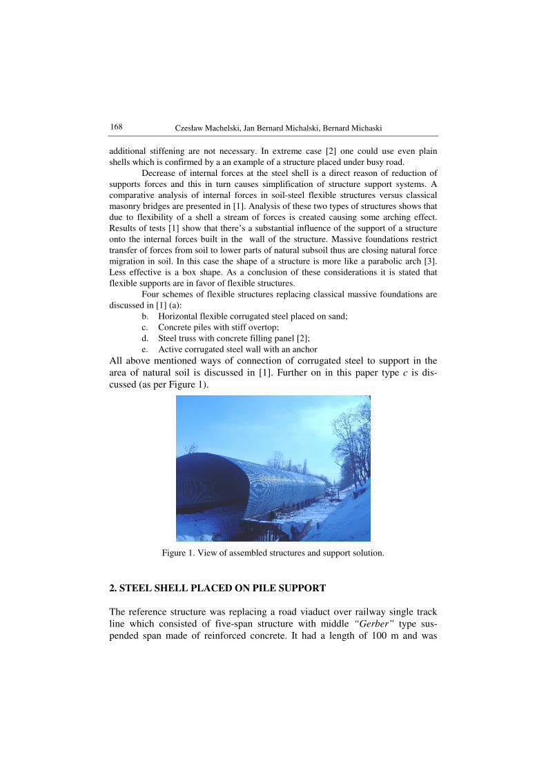
All above mentioned ways of connection of corrugated steel to support in the area of natural soil is discussed in [1]. Further on in this paper type c is dis-cussed (as per Figure 1).
Figure 1. View of assembled structures and support solution.
2. STEEL SHELL PLACED ON PILE SUPPORT
The reference structure was replacing a road viaduct over railway single track line which consisted of five-span structure with middle “Gerber” type sus-pended span made of reinforced concrete. It had a length of 100 m and was
Case study of steel shell structure supported on piles 169
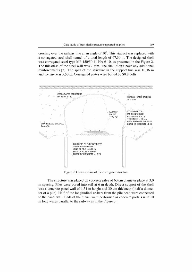
crossing over the railway line at an angle of 300. This viaduct was replaced with a corrugated steel shell tunnel of a total length of 67,30 m. The designed shell was corrugated steel type MP 150/50 41 HA 6-10, as presented in the Figure 2. The thickness of the steel wall was 7 mm. The shell didn’t have any additional reinforcements [3]. The span of the structure in the support line was 10,36 m and the rise was 5,50 m. Corrugated plates were bolted by S8.8 bolts.
CONCRETE PILE (REINFORCED)
DIAMETER = 600 mm.
LONG OF PILE = 6,00 m.
SPAN OF PILES = 3,00 m
GRADE OF CONCRETE = B-25
CORRUGATED STRUCTURE
MP 41 HA 6 - 10
COARSE-SAND BACKFILL
Is = 0,98
RAILWAY
GAUGE
TYPE "C"
STIFF OVERTOP
(AS REINFORCED
RETAINING WALL)
THICKNESS = 30 cm
COARSE - SAND BACKFILL
Is = 0,98
Figure 2. Cross section of the corrugated structure
The structure was placed on concrete piles of 60 cm diameter place at 3,0
m spacing. Piles were bored into soil at 6 m depth. Direct support of the shell was a concrete panel wall of 1,54 m height and 30 cm thickness ( half a diame-ter of a pile). Half of the longitudinal re-bars from the pile head were connected to the panel wall. Ends of the tunnel were performed as concrete portals with 10 m long wings parallel to the railway as in the Figure 3 .
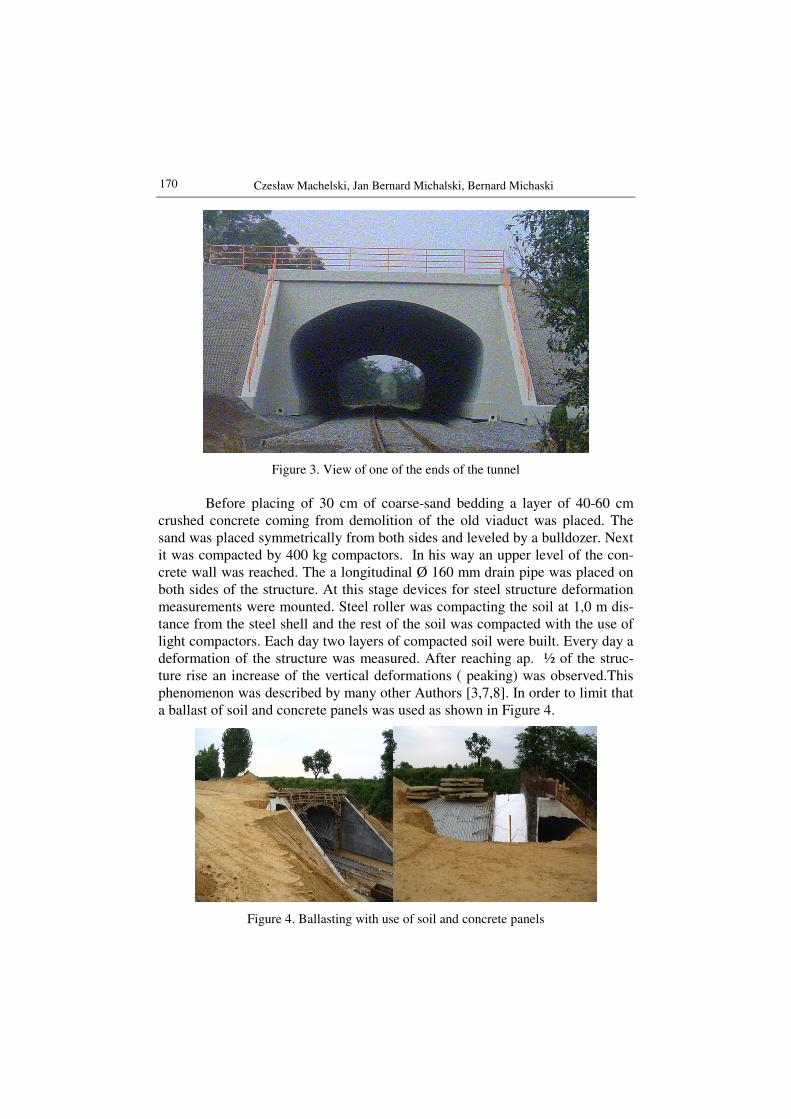
170 Czesław Machelski, Jan Bernard Michalski, Bernard Michaski
Figure 3. View of one of the ends of the tunnel
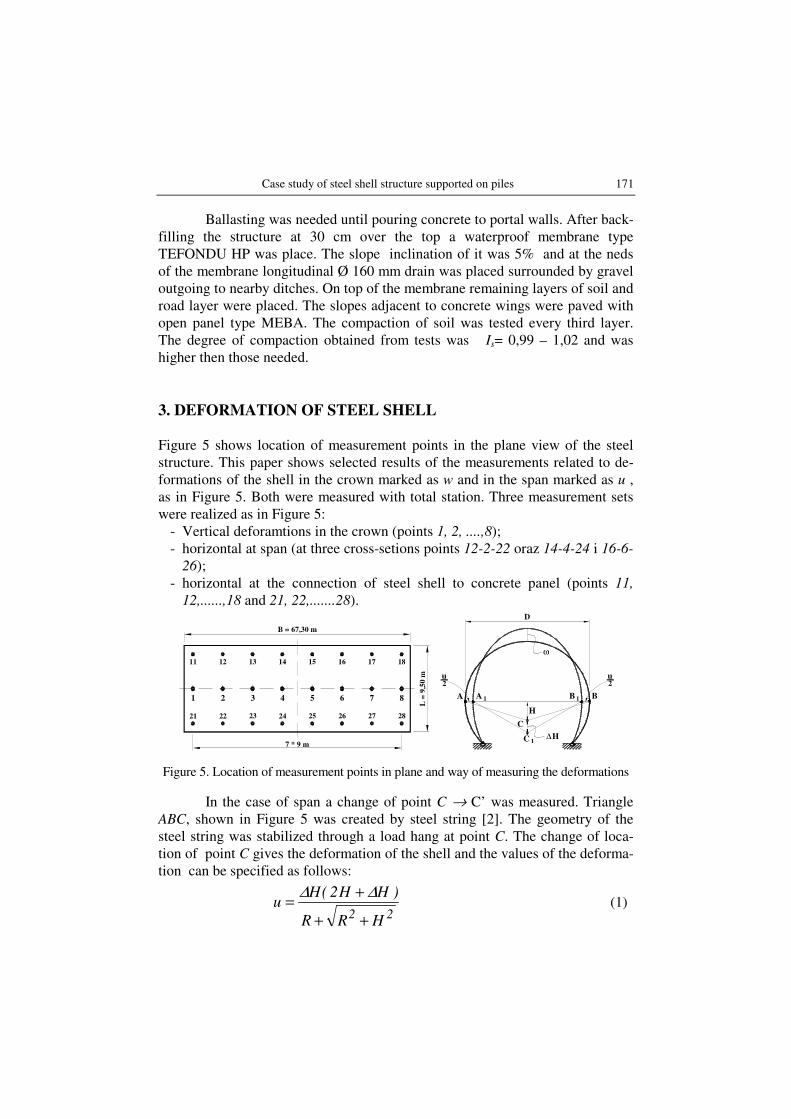
Before placing of 30 cm of coarse-sand bedding a layer of 40-60 cm
crushed concrete coming from demolition of the old viaduct was placed. The sand was placed symmetrically from both sides and leveled by a bulldozer. Next it was compacted by 400 kg compactors. In his way an upper level of the con-crete wall was reached. The a longitudinal Ø 160 mm drain pipe was placed on both sides of the structure. At this stage devices for steel structure deformation measurements were mounted. Steel roller was compacting the soil at 1,0 m dis-tance from the steel shell and the rest of the soil was compacted with the use of light compactors. Each day two layers of compacted soil were built. Every day a deformation of the structure was measured. After reaching ap. ½ of the struc-ture rise an increase of the vertical deformations ( peaking) was observed.This phenomenon was described by many other Authors [3,7,8]. In order to limit that a ballast of soil and concrete panels was used as shown in Figure 4.
Figure 4. Ballasting with use of soil and concrete panels
Case study of steel shell structure supported on piles 171
Ballasting was needed until pouring concrete to portal walls. After back-filling the structure at 30 cm over the top a waterproof membrane type TEFONDU HP was place. The slope inclination of it was 5% and at the neds of the membrane longitudinal Ø 160 mm drain was placed surrounded by gravel outgoing to nearby ditches. On top of the membrane remaining layers of soil and road layer were placed. The slopes adjacent to concrete wings were paved with open panel type MEBA. The compaction of soil was tested every third layer. The degree of compaction obtained from tests was Is= 0,99 – 1,02 and was higher then those needed.
3. DEFORMATION OF STEEL SHELL
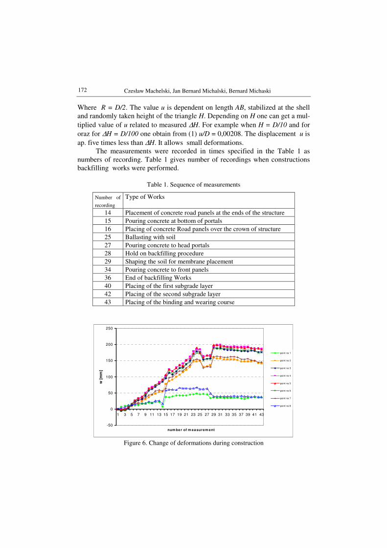
Figure 5 shows location of measurement points in the plane view of the steel structure. This paper shows selected results of the measurements related to de-formations of the shell in the crown marked as w and in the span marked as u , as in Figure 5. Both were measured with total station. Three measurement sets were realized as in Figure 5:
- Vertical deforamtions in the crown (points 1, 2, ....,8); - horizontal at span (at three cross-setions points 12-2-22 oraz 14-4-24 i 16-6-
26); - horizontal at the connection of steel shell to concrete panel (points 11,
12,......,18 and 21, 22,.......28).
1 2 3 4 5 6 7 8
11 12 13 14 15 16 17 18
21 22 23 24 25 26 27 28
B = 67,30 m
7 * 9 m
L =
9,5
0 m
ω
H
∆H
u
C
C
A A B B
u
D
2 2
1 1
1
Figure 5. Location of measurement points in plane and way of measuring the deformations
In the case of span a change of point C → C’ was measured. Triangle ABC, shown in Figure 5 was created by steel string [2]. The geometry of the steel string was stabilized through a load hang at point C. The change of loca-tion of point C gives the deformation of the shell and the values of the deforma-tion can be specified as follows:
22
HRR
)HH2(Hu
++
+=
∆∆ (1)
172 Czesław Machelski, Jan Bernard Michalski, Bernard Michaski
Where R = D/2. The value u is dependent on length AB, stabilized at the shell and randomly taken height of the triangle H. Depending on H one can get a mul-
tiplied value of u related to measured ∆H. For example when H = D/10 and for
oraz for ∆H = D/100 one obtain from (1) u/D = 0,00208. The displacement u is
ap. five times less than ∆H. It allows small deformations. The measurements were recorded in times specified in the Table 1 as
numbers of recording. Table 1 gives number of recordings when constructions backfilling works were performed.
Table 1. Sequence of measurements
-50
0
50
100
150
200
250
1 3 5 7 9 11 13 15 17 19 21 23 25 27 29 31 33 35 37 39 41 43
num be r of m ea surem ent
w [
mm
]
point no 1
point no 2
point no 3
point no 4
point no 5
point no 6
point no 7
point no 8
Figure 6. Change of deformations during construction
Number of
recording
Type of Works
14 Placement of concrete road panels at the ends of the structure
15 Pouring concrete at bottom of portals
16 Placing of concrete Road panels over the crown of structure
25 Ballasting with soil
27 Pouring concrete to head portals
28 Hold on backfilling procedure
29 Shaping the soil for membrane placement
34 Pouring concrete to front panels
36 End of backfilling Works
40 Placing of the first subgrade layer
42 Placing of the second subgrade layer
43 Placing of the binding and wearing course
Case study of steel shell structure supported on piles 173
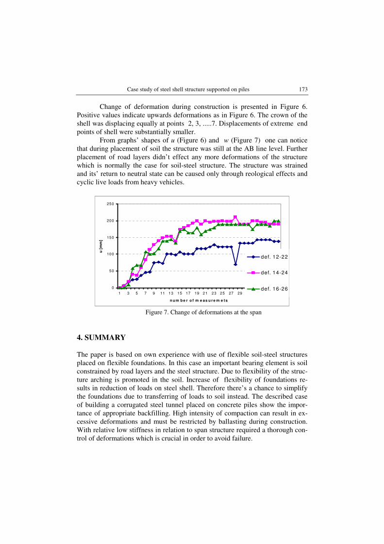
Change of deformation during construction is presented in Figure 6. Positive values indicate upwards deformations as in Figure 6. The crown of the shell was displacing equally at points 2, 3, .....7. Displacements of extreme end points of shell were substantially smaller.
From graphs’ shapes of u (Figure 6) and w (Figure 7) one can notice that during placement of soil the structure was still at the AB line level. Further placement of road layers didn’t effect any more deformations of the structure which is normally the case for soil-steel structure. The structure was strained and its’ return to neutral state can be caused only through reological effects and cyclic live loads from heavy vehicles.
0
50
100
150
200
250
1 3 5 7 9 11 13 15 17 19 21 23 25 27 29 31 33 35 37
n u m b e r o f m e as u r e m e t s
u [
mm
]
def. 12-22
def. 14-24
def. 16-26
Figure 7. Change of deformations at the span
4. SUMMARY
The paper is based on own experience with use of flexible soil-steel structures placed on flexible foundations. In this case an important bearing element is soil constrained by road layers and the steel structure. Due to flexibility of the struc-ture arching is promoted in the soil. Increase of flexibility of foundations re-sults in reduction of loads on steel shell. Therefore there’s a chance to simplify the foundations due to transferring of loads to soil instead. The described case of building a corrugated steel tunnel placed on concrete piles show the impor-tance of appropriate backfilling. High intensity of compaction can result in ex-cessive deformations and must be restricted by ballasting during construction. With relative low stiffness in relation to span structure required a thorough con-trol of deformations which is crucial in order to avoid failure.
174 Czesław Machelski, Jan Bernard Michalski, Bernard Michaski
REFERENCES
1. MACHELSKI CZ., JANUSZ L., MICHALSKI J. B., MICHALSKI B.: Flexible
Foundations of Soil-Steel Shell Bridges, International Conference “EKO MOST 2006”, Kielce 16-17 may 2006, pp. 261–268.
2. MACHELSKI Cz., ANTONISZYN G., MICHALSKI B.: Live Load Effects on a
Soil-Steel Bridge Founded on Elastic Supports Studia Geotechnica et Me-chanica, 2006, Vol. XXVIII, No. 3–4, pp. 91–.
3. Handbook of Steel Drainage & Highway Construction Products, Corrugated Steel Pipe Institute& American Iron and Steel Institute, Second Canadian Edition, 2002.
4. KUNECKI B., KUBICA E., Full-Scale Laboratory Tests and FEM Analysis of Corrugated Steel Culverts under Standardized Railway Load, Archives of Civil and Mechanical Engineering, 2004, Vol. IV, No. 4, pp. 41–53.
5. MACHELSKI Cz., ANTONISZYN G., Influence of Live Loads on the Soil-Steel Bridge Structures, Studia Geotechnica et Mechanica, 2004, Vol. XXVI, No. 3–4, pp. 91–119.
6. MACHELSKI Cz., ANTONISZYN G., Load rate of the circumferential sector of
soil-steel bridge structures, Archives of Civil and Mechanical Engineering, 2005, Vol. V, No. 4, pp. 85–102.
7. MIRZA C., BAKHT B., Soil-steel structure design by the Ontario Code: Part
1. General and geotechnical considerations, Canadian Journal of Civil En-gineering, 1981, Vol. 8, No 3, pp. 317–330.
8. VASLESTAD J., Soil Structure Interaction of Buried Culverts, Institutt for Geoteknikk, Norges Tekniske Hogskole, Universitetet I Trondheim, 1990.
STUDIUM PRZYPADKU ZASTOSOWANIA STALOWEJ KONSTRUKCJI
PODATNEJ OPARTEJ NA PALACH
Streszczenie
Referat prezentuje własne doświadczenia z budowy podatnych podpór pod konstrukcja-
mi stalowo-gruntowymi. Szczególną cechą tych fundamentów są technologiczne uprosz-
czenia głównie przy trudnych warunkach podłoża w okolicy cieków i dróg. Możliwości
znacznej redukcji rozmiaru fundamentów powiązane są z redystrybucją sił wewnętrznych
z powłoki stalowej do gruntu. Przykład prototypu konstrukcji osadzonej na profilach
stalowych wykazuje możliwość zredukowania zaprojektowanych fundamentów lub uży-
cie nowych, nie rozpatrywanych dotąd rozwiązań. Rezultaty przedstawione w referacie
wykazują potrzebę odpowiedniego zagęszczenia gruntu. Nadmierne zagęszczenie gruntu
może negatywnie wpływać na współdziałanie konstrukcji z podłożem.
Słowa kluczowe: podatne podpory, mosty stalowo-gruntowe, technologia